pump model: serial no: po no: - peerless pump … iom ols vtp part 1.pdf · disassembling peerless...
TRANSCRIPT

Bulletin 2633119
SERVICE INSTRUCTIONS
VERTICAL TURBINE PUMPS OPEN LINE SHAFT CONSTRUCTION
PUMP MODEL: _________________
SERIAL NO: ____________________
PO NO: _________________________
Peerless Pump Company 2005 Dr. M.L. King Jr. Street P.O. Box 7026 Indianapolis, IN 46207-7026 Telephone: main 317-925-9661 Fax: 317-924-7326 www.peerlesspump.com
2
IMPORTANT SAFETY PRECAUTIONS
Before opening the conduit box of an electric motor, be certain that the current to the motor is shut off. An electrical shock from contact with live motor leads can be fatal. The driver cover must be in place when the pump is in operation. Rotating parts below this cover could cause grave personal injury if exposed. Petroleum-base cleaning solvents are flammable. Smoking by personnel in the vicinity of these solvents is extremely hazardous and must not be permitted.
Pump parts, and the tools and rigging equipment used in installing pumps, are heavy and may easily cause personal injury if dropped or carelessly handled. The normal precautions and safety rules associated with the erection of heavy machinery, in regard to manual lifting, use of power equipment, and handling of tools, must be observed in the installation of this pump. Do not work under a heavy suspended object unless there is a positive support under it to stop its fall in event of sling of hoist failure. Disregard of the warning could result in grave personal injury.
CONTENTS
SECTION PAGE 1. MATERIALS AND EQUIPMENT REQUIRED……................................ 5 2. CHECKING THE WELL…………………………………………………… 5 3. DEVELOPING THE WELL………………….............................................. 6 4. BUILDING THE FOUNDATION………………......................................... 7 5. UNLOADING THE PARTS………………….............................................. 9 6. PREPARING THE PARTS FOR INSTALLATION…….......................... 10 7. INSTALLING THE BOWL UNIT AND COLUMN.................................. 12 8. INSTALLING THE DISCHARGE HEAD.................................................. 18 9. ALIGNING THE PUMP............................................................................... 23 10. INSTALLING THE PACKING................................................................... 24 11. INSTALLING THE DRIVER...................................................................... 29 12. GROUTING THE DISCHARGE HEAD.................................................... 31 13. INSTALLING THE DISCHARGE PIPING............................................... 31 14. PRE-LUBRICATING THE SHAFT BEARINGS....................................... 32 15. ADJUSTING THE IMPELLERS.................................................................. 34 16. STARTING THE PUMP................................................................................ 38 17. ADJUSTING THE PACKING GLAND....................................................... 39 18. DISASSEMBLING THE PUMP................................................................... 39 19. INSTALLING AND OPERATING THE WATER LEVEL TESTING SYSTEM...........................................................42

INTRODUCTION The manual gives detailed instructions for installing, adjusting, operating, servicing and disassembling Peerless Vertical Turbine Pumps. In addition, instructions are included for installing and operating a water level system using air pressure. Proper installation and maintenance of this pump will contribute to maximum efficiency and long, trouble-free life. Before starting the installation, review the entire procedure given in the manual, omitting those portions which do not apply to the particular pump to be installed; then refer to it step by step during the actual procedure. Retain the manual for future use in solving maintenance problems.
NOTICE
Peerless Pump cannot be held responsible for inadequate performance of or damage to a pump or for injury to personnel due to any of the following causes.
Installation of the pump in a well which is unsuitable as tested by the procedure described in Section 2 of this manual. Installation of the pump on an inadequate foundation. Air or gas in the well. If there is evidence of air or gas, consult your Peerless Pump dealer. Erosion of pump parts by sand in the water (sand cutting). Restarting of a pump whose impellers are packed with sand (sand locked).
WARNING
The pumps described by this manual are specifically designed for pumping water, and must not be used to pump any other fluid particularly combustible fluids. These pumps must not be installed in any manner except as specified herein, and must not be operated at speeds, capacities, pressures or temperatures other than those stipulated for the order. VIOLATION OF THESE WARNINGS MAY RESULT IN SEVERE PROPERTY DAMAGE OR GRAVE PERSONAL INJURY.

SECTION 1
MATERIALS AND EQUIPMENT REQUIRED The materials and equipment necessary for installation will vary with the size of the pump and the type of installation. The following list is offered only as a guide. A. BULK MATERIAL
Thread compound Lubrication oil (such as automotive engine
oil) Grease (See Table 10-2) Solvent, petroleum-base (such as gasoline,
kerosene or distillate) Grouting material
B. RIGGING EQUIPMENT
Mobile power hoist - or a derrick, lifting windlass and blocks
Sling Elevator clamp (2) Clamp - to attach dragline block to edge of
pipe Capstan Drive (cat head and cat line) for
making threaded joints (optional)
Tail rope - size and length as required. Special clamping tool (See Fig. 7-6) -
optional Timbers - size and length as required to
support long pump parts on the ground. Timbers - size and length as required to
support pump parts suspended in the well. C. HAND TOOLS
Chain tongs (2) Pipe wrench Pipe cutter or hacksaw File Wire brush Pliers Wire cutters Pocket knife Wrenches - open-end, and box or socket Clean rags Apron (wood or metal) - to protect top of
bowl unit or column section from entry of foreign matter Set of mechanic’s hand tools
SECTION 2
CHECKING THE WELL
Before any attempt is made to install the pump, the well should be carefully checked to determine that the casing is of the proper diameter, depth and straightness. A suggested method of doing this is to lower into the well a pipe which is the same diameter as the bowl unit of the intended pump and 1-½ times the length of the bowl unit. If this test pipe can be lowered
into the required depth, it may be assumed that the well is suitable for the pump. DO NOT INSTALL THE PUMP IN A WELL INTO WHICH THE TEST PIPE CANNOT BE LOWERED TO THE REQUIRED DEPTH.

SECTION 3
DEVELOPING THE WELL A. Developing the well and freeing it from sand is part of the well driller’s job, and should be done with a test pump reserved the this service. B. NOTE
If a test pump is not available and there is no alternative except to use the new pump, raise the impellers at least 3/16 inch above their normal running position. (See Section 15 for method of adjusting impellers.) Once started, the pump must not be stopped until the water is free of sand.
Despite these precautions, the pump may still be damaged by sand cutting. C. If, for any reason, the pump is stopped while pumping water containing sand, the pump may become “sand-locked”. Sand-locking is the condition that occurs when the clearances between impellers and bowls are packed with sand which settles in the bowl unit after the pump stops rotating and the water drains back into the well.
CAUTION
If a sand-locked pump is restarted, severe damage may result.
D. If a pump is accidentally stopped while pumping sandy water, sand-locking may be overcome by the following procedure:
1. As soon as the pump shaft stops rotating, raise the impellers to their top position. (See Section 15 for method of adjusting impellers.) 2. Alternately raise and lower the impeller a small amount to loosen the trapped sand. 3. Rotate the shaft alternately clockwise and counter-clockwise by applying a wrench to the drive coupling. This too has the effect of loosening the sand, permitting it to fall back into the well. 4. If a separate water supply is available, flush the pump with clear water.
E. If all attempts to free the impellers fail, it will be necessary to pull the pump. The obstruction can then be cleared by back-flushing, or, if necessary, by disassembling the bowl unit.

SECTION 4
BUILDING THE FOUNDATION
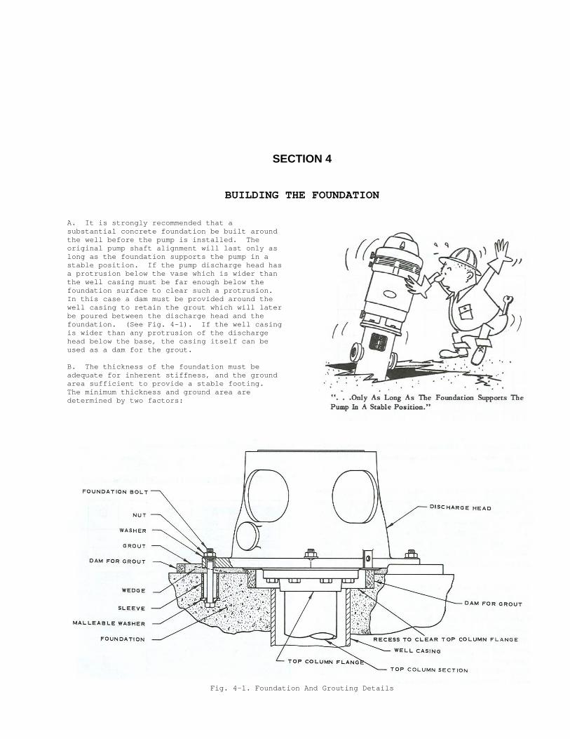
A. It is strongly recommended that a substantial concrete foundation be built around the well before the pump is installed. The original pump shaft alignment will last only as long as the foundation supports the pump in a stable position. If the pump discharge head has a protrusion below the vase which is wider than the well casing must be far enough below the foundation surface to clear such a protrusion. In this case a dam must be provided around the well casing to retain the grout which will later be poured between the discharge head and the foundation. (See Fig. 4-1). If the well casing is wider than any protrusion of the discharge head below the base, the casing itself can be used as a dam for the grout. B. The thickness of the foundation must be adequate for inherent stiffness, and the ground area sufficient to provide a stable footing. The minimum thickness and ground area are determined by two factors:
Fig. 4-1. Foundation And Grouting Details

1. The firmness of the supporting earth, considering adverse effects of rain and flooding. 2. The total weight of the complete pumping unit when full of water. Total load on foundation = Weight of all parts + Weight of water in column. Table 4-1, 15-2 may be used for reference in figuring the size of the foundation.
C. Structural foundations when properly constructed are satisfactory for some installations. A combination of structural members and concrete may also be satisfactory in same cases. However, foundations made up of structural members (steel or wood) spread on unstable soil are definitely not satisfactory. They are certain to shift or warp, causing misalignment, which will result in damage to the pump. Table 4-1. Approximate Weight of Water-Filled Pump Column.
Nom. Pipe Size
Sched- ule
Wt. per
Ft. of pipe
Wt. of Water Per Ft
of Pipe
Total Wt. Per Ft.*
3 40S 7.58 3.0 10.6
4 40S 10.79 5.0 15.8
5 40S 14.62 8.0 22.6
6 40S 18.97 12.0 31.0
8 30 24.70 20.0 44.7
10 30 34.24 23.0 57.2
12 30 43.77 48.0 91.8
14 30S 54.57 57.0 111.6
16 30S 62.58 76.0 138.6
18 30 82.06 97.0 179.1
20 30X 104.13 120.0 224.1
24 30X 125.49 177.0 302.5
* Multiply the appropriate figure by the total length of the column, and add the weight of the shafting, tubing, discharge head, bowl unit and the driver to obtain the total load on the foundation. D. Foundation bolts (hold-down, or anchor, bolts) are mot required for pumps with discharge pressures less than 10 psi and column lengths greater than 50 feet, when driven by a motor or steam turbine or through a right-angle gear unit. Pumps with column lengths 50 feet or less, or discharge pressures of 10 psi or more, and all pumps which are belt-driven, should be anchored by sleeve-type, or equivalent, foundation bolts. (See Fig. 4-1.) Sleeve-type bolts are recommended because they allow some flexibility in the final positioning of the discharge head. They are also
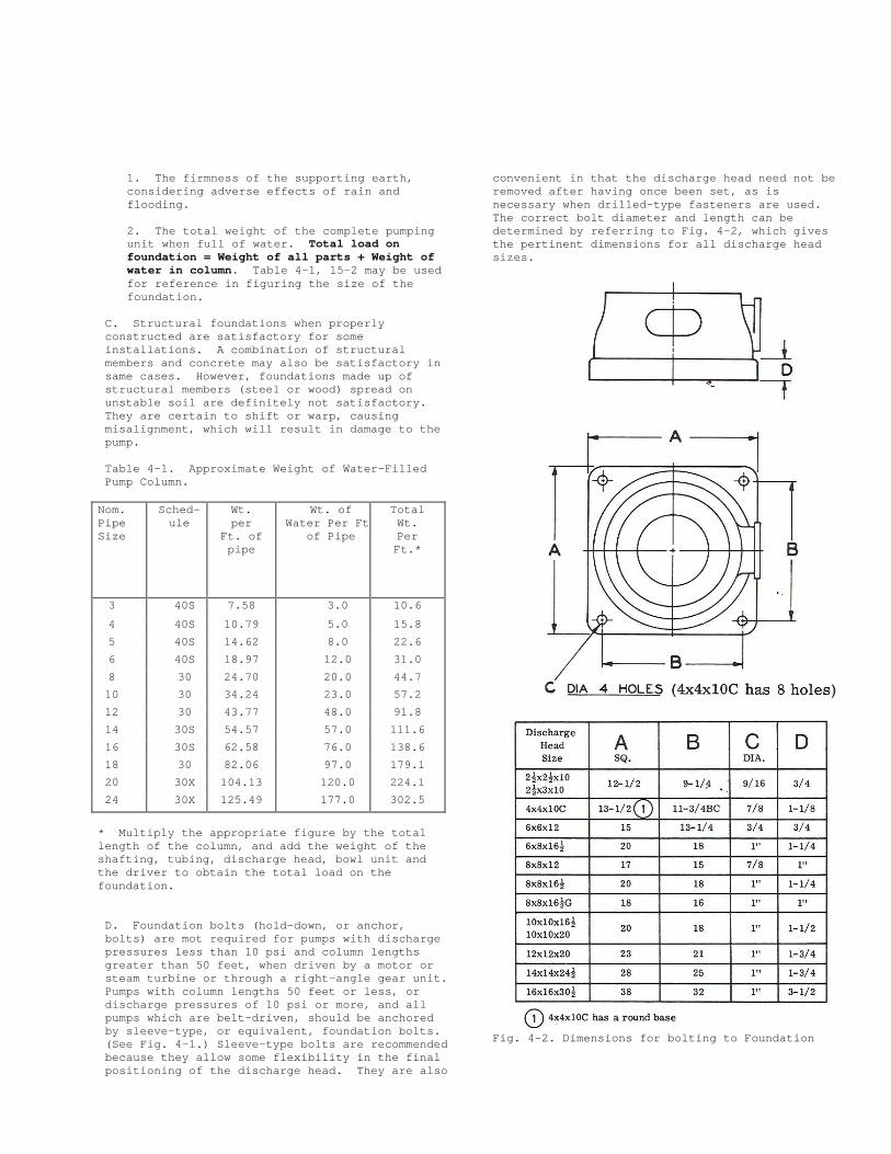
convenient in that the discharge head need not be removed after having once been set, as is necessary when drilled-type fasteners are used. The correct bolt diameter and length can be determined by referring to Fig. 4-2, which gives the pertinent dimensions for all discharge head sizes.
Fig. 4-2. Dimensions for bolting to Foundation
It is recommended that a template be made for accurately locating the foundation bolts. See Fig. 4-2 for the correct spacing. Some pumps are provided with a sole plate which fits between the discharge head and the foundation. In this case the foundation bolts must align with the holes in the sole plate rather than those in the discharge head. E. Observe the usual rules of good workmanship in regard to mixing, pouring, working and curing of concrete foundations. Allow the foundation to cure at least 48 hours before starting the pump installation.
NOTE
Be sure to position the foundation and locate the foundation bolts so that the discharge head will be in accurate alignment with the discharge piping.
SECTION 5
UNLOADING THE PARTS
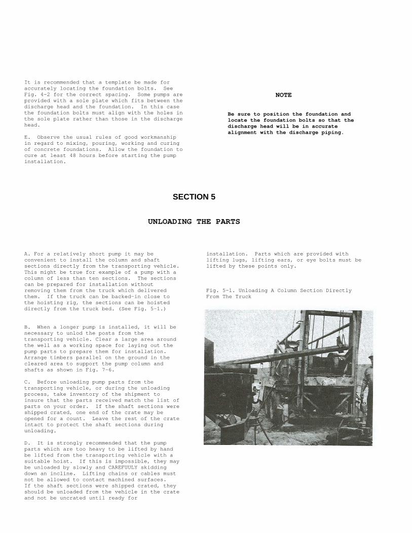
A. For a relatively short pump it may be convenient to install the column and shaft sections directly from the transporting vehicle. This might be true for example of a pump with a column of less than ten sections. The sections can be prepared for installation without removing them from the truck which delivered them. If the truck can be backed-in close to the hoisting rig, the sections can be hoisted directly from the truck bed. (See Fig. 5-1.) B. When a longer pump is installed, it will be necessary to unlod the posts from the transporting vehicle. Clear a large area around the well as a working space for laying out the pump parts to prepare them for installation. Arrange timbers parallel on the ground in the cleared area to support the pump column and shafts as shown in Fig. 7-6. C. Before unloading pump parts from the transporting vehicle, or during the unloading process, take inventory of the shipment to insure that the parts received match the list of parts on your order. If the shaft sections were shipped crated, one end of the crate may be opened for a count. Leave the rest of the crate intact to protect the shaft sections during unloading. D. It is strongly recommended that the pump parts which are too heavy to be lifted by hand be lifted from the transporting vehicle with a suitable hoist. If this is impossible, they may be unloaded by slowly and CAREFUULY skidding down an incline. Lifting chains or cables must not be allowed to contact machined surfaces. If the shaft sections were shipped crated, they should be unloaded from the vehicle in the crate and not be uncrated until ready for
installation. Parts which are provided with lifting lugs, lifting ears, or eye bolts must be lifted by these points only. Fig. 5-1. Unloading A Column Section Directly From The Truck
CAUTION
Column and shaft sections must be handled with extreme care. These parts are machined to achieve precision alignment. If dropped, sprung or otherwise mistreated, misalignment, poor performance and ultimate failure will result. Shafts are especially sensitive to abuse. Bent or damaged shafts must not be used. Doing so is certain to result in pump failure.
E. Certain extra-long, relatively small-diameter bowl units are shipped attached to skids bearing this special notation:
“CAUTION - DO NOT REMOVE THIS PROTECTIVE SKID UNTIL THE BOWL UNIT IS IN VERTICAL POSITION, READY TO BE INSTALLED IN THE WELL. RETAIN THIS SKID FOR USE WHEN REMOVING THE BOWL UNIT FROM THE WELL”
It is very important that this precaution be observed in handling these units.
SECTION 6
PREPARING THE PARTS FOR INSTALLATION
A. The hoisting rig should now be set up. the installation given in this manual are based upon the use of mobile power-operated hoist such as that shown in Fig. 7-1. This affords the greatest convenience for pump installation. If any other hoisting arrangement is used, it will be necessary for the installer to interpret these instructions to suit the requirements of his equipment. B. All of the pump parts were carefully inspected before leaving the factory, but may have become soiled or damaged in shipping and handling. Therefore, all parts must be inspected by the installer to ascertain that they are clean and undamaged before installing them in the well. Check all column and shaft sections to be sure that they have not been bent, and that machined surfaces are not marred in any way, especially the butting surfaces at the ends and screw threads. A procedure for testing shaft straightness is specified in Part H. C. If the shaft sections were received crated, they should be removed from the crate at this time. Except for the threaded ends, which are covered with a rust-inhibiting oil, and the monel sleeves, the shaft sections are protected with a special coating. Lay the shaft sections
across the parallel timbers previously placed on the ground (Section 5, Part B.) Wash off the protective oil from the threads with petroleum-base solvent, and wipe thoroughly clean and dry. Clean the shaft couplings, if necessary, and store in a clean container until ready for use. D. The pump column sections are furnished with threaded ends ad are usually shipped with a coupling attached to one end. Inspect the coupling for correct thread engagement: one-half the length of the coupling, minus one-half the thickness of the bearing retainer. If the couplings are not already attached, they are packed separately. Lubricate the thread at one end of each column section, using ordinary automotive engine oil or thread compound, and screw on the couplings to their proper engagement. E. Most of the total length of the pump is made up of column sections and shaft sections which are equal in length. They will all be five feet or ten feet long, depending upon the particular pump model. The top column section and the top shaft section can be easily identified because their lengths are different form the others. Also, the top shaft section has a keyseat at one end; the top column section is not fitted with a coupling, since the upper end screws directly into the discharge head or into a special flange.
F. Check the total length of the pump bowl unit, suction pipe, and strainer (if furnished) to see whether the hoist clearance is sufficient to handle these assembled parts as a unit. If the clearance is sufficient, assemble the strainer to the suction pipe and the suction pipe to the bowl unit. Lay this assembly across the timbers, close to the well, ready for installation. G. If the assembled strainer, suction pipe, and bowl unit are too long to be handled by the hoist, the strainer and suction pipe will be installed first, and then the bowl unit, separately. If a strainer is furnished, attach it to the suction pipe and lay this assembly across the timbers close to the well, ready for installation. H. CAUTION
When inserting the shaft sections into the column sections, take care not to bend the shaft or damage the threads.
Prepare the column and shaft sections for hoisting by inserting a shaft section into each column section. The special sleeve section on the shaft must be at the end of the column section which has the coupling. Do not insert the top shaft section into the top column section at this time. Assemble all the standard shaft and column sections in this manner, and arrange them on the parallel timbers, next to the bowl unit, with the coupling ends nearest the well. I. If an air line for a water level testing system is to be installed with the pump, 1/4 inch OD copper or plastic tubing should be used. When piping is to be installed, use pipe lengths which are the same length as the column sections. Each pipe should be fitted with a coupling at one end, the thread well lubricated with thread compound to ensure an air-tight seal. J. Copper tie-wires approximately 1/8 inch diameter will be needed to attach the air line to the pump. These should be pre-cut to sufficient length so they can be looped around the air line, twisted, looped around the pump column, and twisted again, with wire to spare. Place the pre-cut tie-wires and the pipe or tubing in a clean area adjacent to the well so that the air line installation can proceed along with the pump installation.
K. Place two short lengths of heavy timber on the foundation, one on each side of the well casing, to support the bowl unit and column sections as the joints are being made. L. Before proceeding with the actual installation, check to see that all the pump parts and equipment have been prepared per Parts A through L of this section.
SECTION 7
INSTALLING THE BOWL UNIT AND COLUMN CAUTION
When making up threaded joints, start the joint by hand to verify that the threads are properly engaged before applying a wrench or a power drive. If cross-threading is suspected, bread the joint immediately and repair the damaged external threads with a file. Clean the threads thoroughly before re-making the joint. If the threads are too deformed to repair with a file, replace the damaged part. When coupling threads are damaged, replace the coupling.
CAUTION
Never attempt to handle or lift the bowl unit by the shaft protruding from the upper end. This could result in bending of the shaft.
If the suction pipe and bowl unit have not been reassembled, start the pump installation at Part A. If the suction pump and bowl unit have been pre-assembled (with or without a strainer), start the pump installation at Part B. A. For the case where the suction pipe and bowl unit have not been pre-assembled:
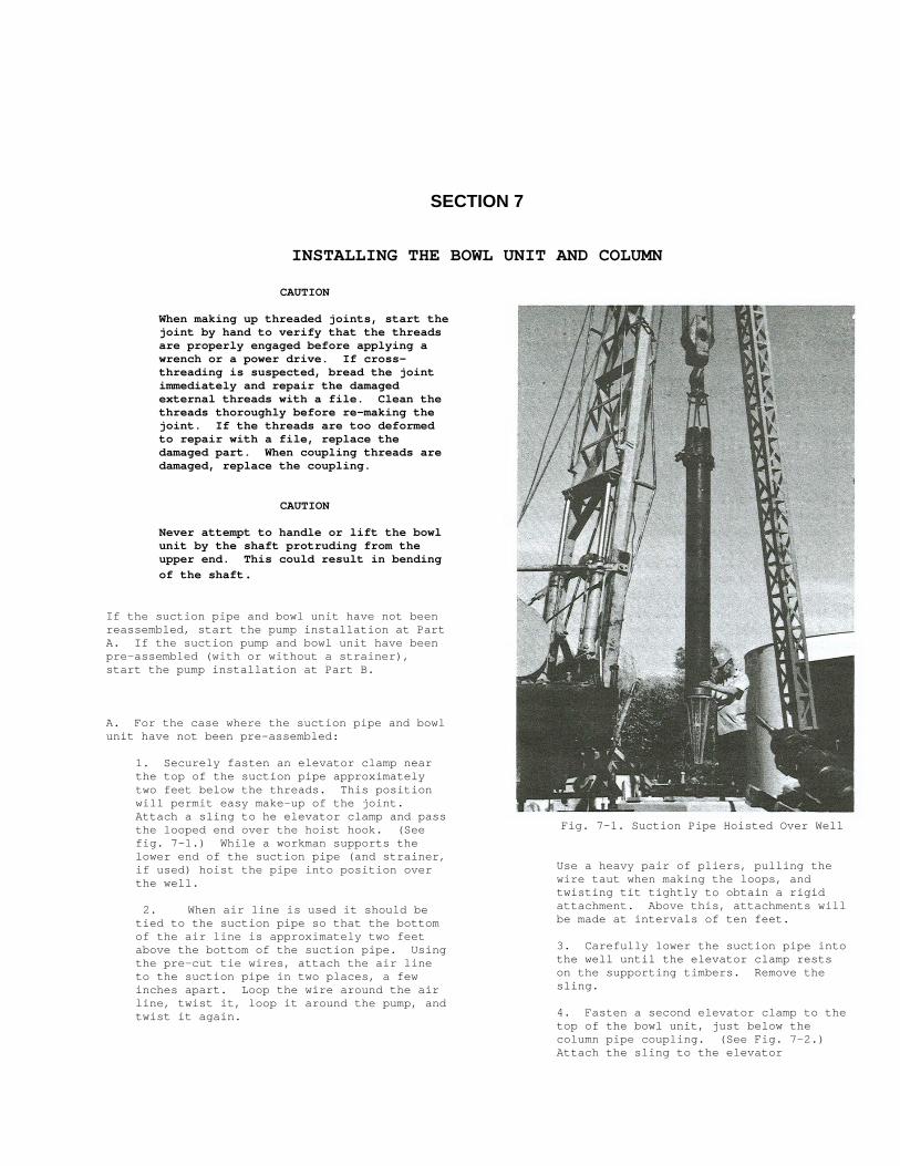
1. Securely fasten an elevator clamp near the top of the suction pipe approximately two feet below the threads. This position will permit easy make-up of the joint. Attach a sling to he elevator clamp and pass the looped end over the hoist hook. (See fig. 7-1.) While a workman supports the lower end of the suction pipe (and strainer, if used) hoist the pipe into position over the well. 2. When air line is used it should be
tied to the suction pipe so that the bottom of the air line is approximately two feet above the bottom of the suction pipe. Using the pre-cut tie wires, attach the air line to the suction pipe in two places, a few inches apart. Loop the wire around the air line, twist it, loop it around the pump, and twist it again.
Fig. 7-1. Suction Pipe Hoisted Over Well
Use a heavy pair of pliers, pulling the wire taut when making the loops, and twisting tit tightly to obtain a rigid attachment. Above this, attachments will be made at intervals of ten feet. 3. Carefully lower the suction pipe into the well until the elevator clamp rests on the supporting timbers. Remove the sling. 4. Fasten a second elevator clamp to the top of the bowl unit, just below the column pipe coupling. (See Fig. 7-2.) Attach the sling to the elevator
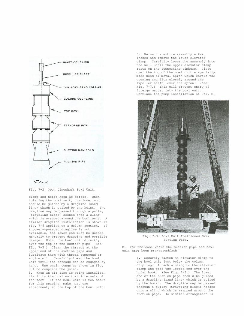
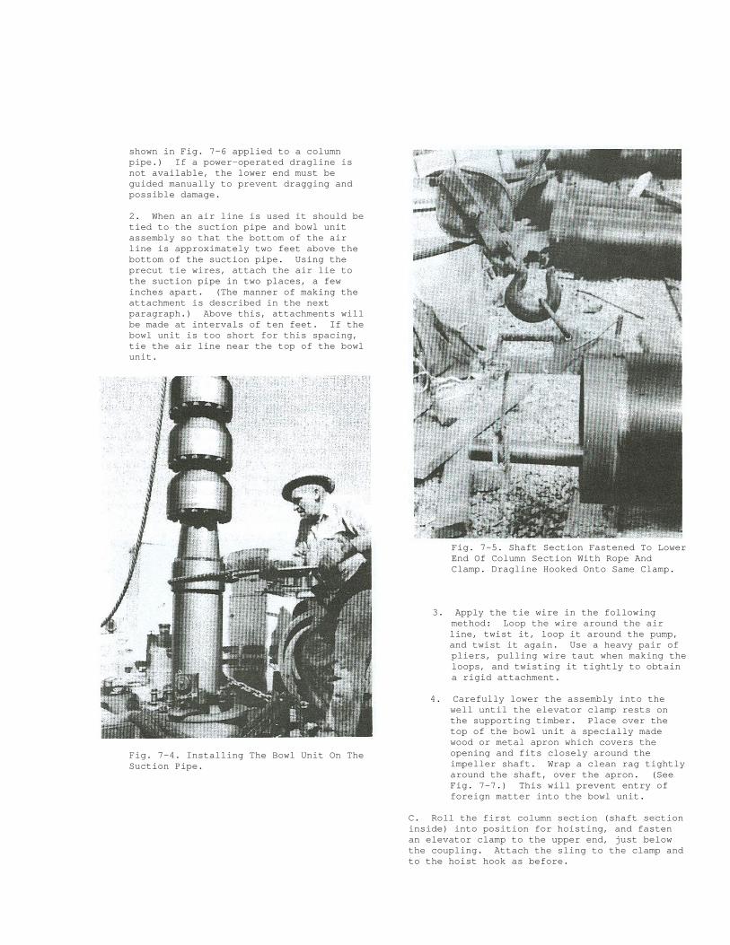
Fig. 7-2. Open Lineshaft Bowl Unit. clamp and hoist hook as before. When hoisting the bowl unit, the lower end should be guided by a dragline (sand line) which is pulled by the hoist. The dragline may be passed through a pulley (traveling block) hooked onto a sling which is wrapped around the bowl unit. A similar dragline installation is shown in Fig. 7-6 applied to a column section. If a power-operated dragline is not available, the lower end must be guided manually to prevent dragging and possible damage. Hoist the bowl unit directly over the top of the suction pipe. (See Fig. 7-3.) Clean the threads at the upper end of the suction pipe and lubricate them with thread compound or engine oil. Carefully lower the bowl unit until the threads can be engaged by hand. Use chain tongs as shown in Fig. 7-4 to complete the joint. 5. When an air line is being installed, tie it to the bowl unit at intervals of ten feet. If the bowl unit is too short for this spacing, make just one attachment, at the top of the bowl unit.
6. Raise the entire assembly a few inches and remove the lower elevator clamp. Carefully lower the assembly into the well until the upper elevator clamp rests on the supporting timbers. Place over the top of the bowl unit a specially made wood or metal apron which covers the opening and fits closely around the impeller shaft, over the apron. (See Fig. 7-7.) This will prevent entry of foreign matter into the bowl unit. Continue the pump installation at Par. C.
Fig. 7-3. Bowl Unit Positioned Over
Suction Pipe. B. For the case where the suction pipe and bowl unit have been pre-assembled:
1. Securely fasten an elevator clamp to the bowl unit just below the column coupling. Attach a sling to the elevator clamp and pass the looped end over the hoist hook. (See Fig. 7-3.) The lower end of the suction pipe should be guided by a dragline (sand line) which is pulled by the hoist. The dragline may be passed through a pulley (traveling block) hooked onto a sling which is wrapped around the suction pipe. (A similar arrangement is
shown in Fig. 7-6 applied to a column pipe.) If a power-operated dragline is not available, the lower end must be guided manually to prevent dragging and possible damage. 2. When an air line is used it should be tied to the suction pipe and bowl unit assembly so that the bottom of the air line is approximately two feet above the bottom of the suction pipe. Using the precut tie wires, attach the air lie to the suction pipe in two places, a few inches apart. (The manner of making the attachment is described in the next paragraph.) Above this, attachments will be made at intervals of ten feet. If the bowl unit is too short for this spacing, tie the air line near the top of the bowl unit.
Fig. 7-4. Installing The Bowl Unit On The Suction Pipe.
Fig. 7-5. Shaft Section Fastened To Lower End Of Column Section With Rope And Clamp. Dragline Hooked Onto Same Clamp.
3. Apply the tie wire in the following method: Loop the wire around the air
line, twist it, loop it around the pump, and twist it again. Use a heavy pair of
pliers, pulling wire taut when making the loops, and twisting it tightly to obtain a rigid attachment.
4. Carefully lower the assembly into the well until the elevator clamp rests on the supporting timber. Place over the top of the bowl unit a specially made wood or metal apron which covers the opening and fits closely around the impeller shaft. Wrap a clean rag tightly around the shaft, over the apron. (See Fig. 7-7.) This will prevent entry of foreign matter into the bowl unit.
C. Roll the first column section (shaft section inside) into position for hoisting, and fasten an elevator clamp to the upper end, just below the coupling. Attach the sling to the clamp and to the hoist hook as before.
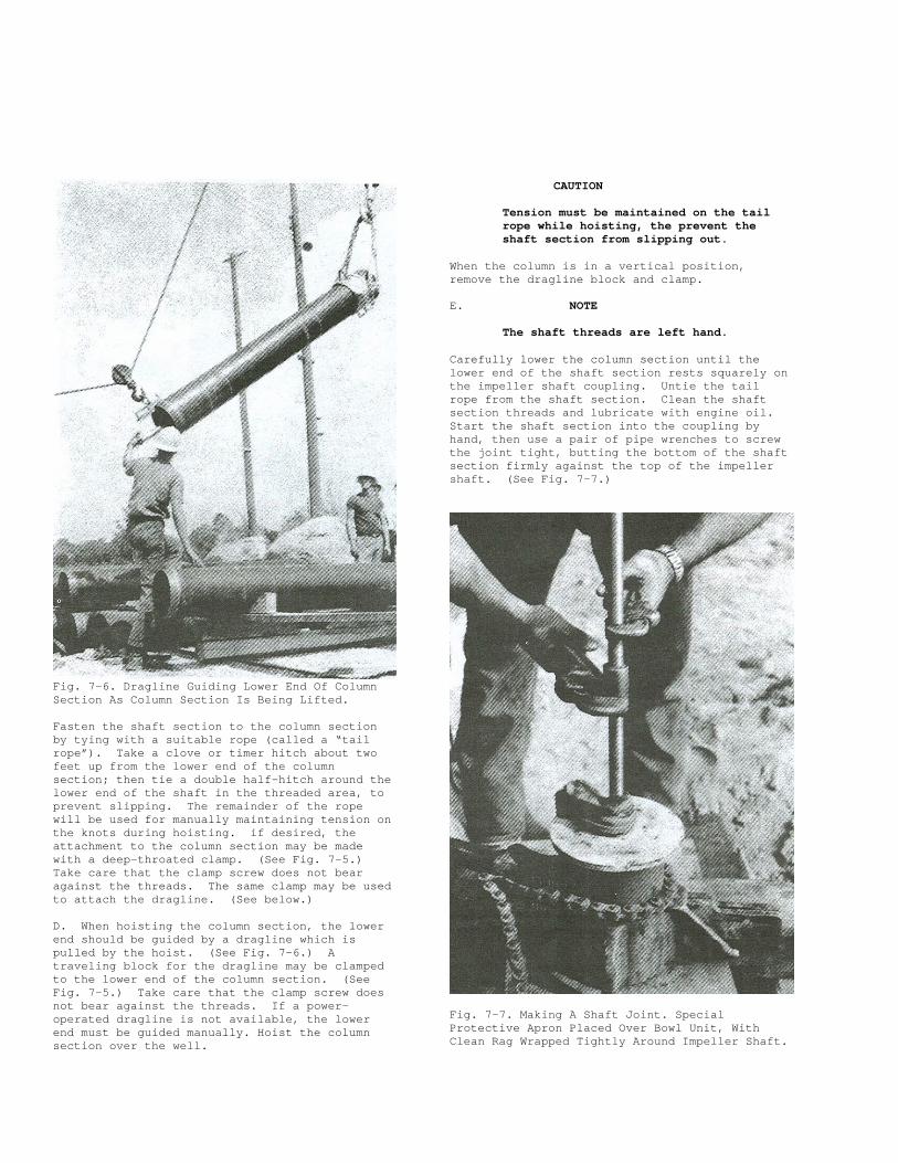
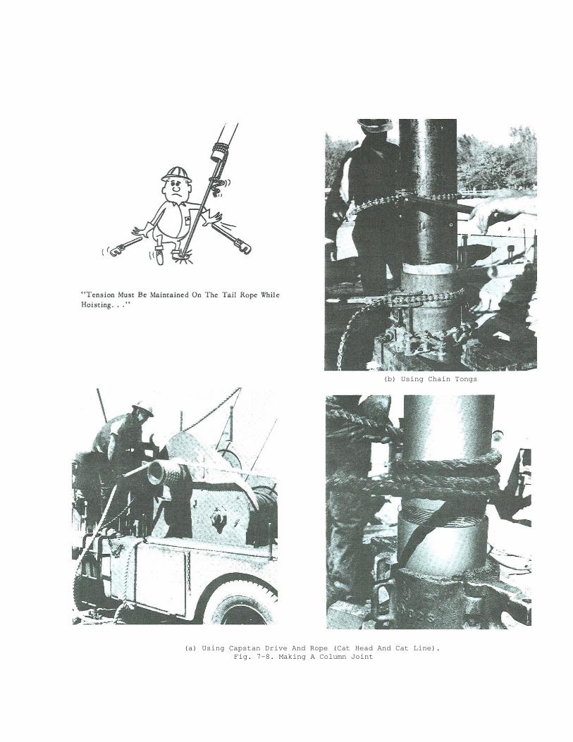
Fig. 7-6. Dragline Guiding Lower End Of Column Section As Column Section Is Being Lifted. Fasten the shaft section to the column section by tying with a suitable rope (called a “tail rope”). Take a clove or timer hitch about two feet up from the lower end of the column section; then tie a double half-hitch around the lower end of the shaft in the threaded area, to prevent slipping. The remainder of the rope will be used for manually maintaining tension on the knots during hoisting. if desired, the attachment to the column section may be made with a deep-throated clamp. (See Fig. 7-5.) Take care that the clamp screw does not bear against the threads. The same clamp may be used to attach the dragline. (See below.) D. When hoisting the column section, the lower end should be guided by a dragline which is pulled by the hoist. (See Fig. 7-6.) A traveling block for the dragline may be clamped to the lower end of the column section. (See Fig. 7-5.) Take care that the clamp screw does not bear against the threads. If a power-operated dragline is not available, the lower end must be guided manually. Hoist the column section over the well.
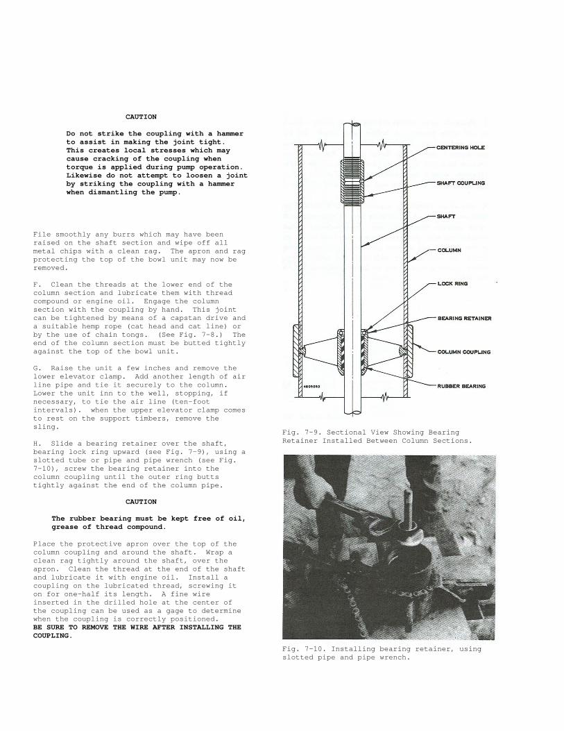
CAUTION Tension must be maintained on the tail rope while hoisting, the prevent the shaft section from slipping out.
When the column is in a vertical position, remove the dragline block and clamp. E. NOTE
The shaft threads are left hand.
Carefully lower the column section until the lower end of the shaft section rests squarely on the impeller shaft coupling. Untie the tail rope from the shaft section. Clean the shaft section threads and lubricate with engine oil. Start the shaft section into the coupling by hand, then use a pair of pipe wrenches to screw the joint tight, butting the bottom of the shaft section firmly against the top of the impeller shaft. (See Fig. 7-7.)
Fig. 7-7. Making A Shaft Joint. Special Protective Apron Placed Over Bowl Unit, With Clean Rag Wrapped Tightly Around Impeller Shaft.
(b) Using Chain Tongs
(a) Using Capstan Drive And Rope (Cat Head And Cat Line). Fig. 7-8. Making A Column Joint
CAUTION
Do not strike the coupling with a hammer to assist in making the joint tight. This creates local stresses which may cause cracking of the coupling when torque is applied during pump operation. Likewise do not attempt to loosen a joint by striking the coupling with a hammer when dismantling the pump.
File smoothly any burrs which may have been raised on the shaft section and wipe off all metal chips with a clean rag. The apron and rag protecting the top of the bowl unit may now be removed. F. Clean the threads at the lower end of the column section and lubricate them with thread compound or engine oil. Engage the column section with the coupling by hand. This joint can be tightened by means of a capstan drive and a suitable hemp rope (cat head and cat line) or by the use of chain tongs. (See Fig. 7-8.) The end of the column section must be butted tightly against the top of the bowl unit. G. Raise the unit a few inches and remove the lower elevator clamp. Add another length of air line pipe and tie it securely to the column. Lower the unit inn to the well, stopping, if necessary, to tie the air line (ten-foot intervals). when the upper elevator clamp comes to rest on the support timbers, remove the sling. H. Slide a bearing retainer over the shaft, bearing lock ring upward (see Fig. 7-9), using a slotted tube or pipe and pipe wrench (see Fig. 7-10), screw the bearing retainer into the column coupling until the outer ring butts tightly against the end of the column pipe.
CAUTION
The rubber bearing must be kept free of oil, grease of thread compound.
Place the protective apron over the top of the column coupling and around the shaft. Wrap a clean rag tightly around the shaft, over the apron. Clean the thread at the end of the shaft and lubricate it with engine oil. Install a coupling on the lubricated thread, screwing it on for one-half its length. A fine wire inserted in the drilled hole at the center of the coupling can be used as a gage to determine when the coupling is correctly positioned. BE SURE TO REMOVE THE WIRE AFTER INSTALLING THE COUPLING.
Fig. 7-9. Sectional View Showing Bearing Retainer Installed Between Column Sections.
Fig. 7-10. Installing bearing retainer, using slotted pipe and pipe wrench.
J. Hoist the next column section (shaft section inside) in the same manner as before, and couple the new shaft and column sections to the preceding sections per Parts E and F. The lower end of the new column section must butt tightly against the rim of the bearing retainer. Attach an additional length of air line, if applicable, and lower the unit into the well per Part G. K. Install the remaining standard-length shaft and column sections and remaining bearing retainers in the same manner. When the last standard-length column section has been screwed in place, raise the entire unit a few inches and remove the lower elevator clamp. Lower the unit into the well until the upper elevator clamp comes to rest on the supporting timbers. Remove the sling.
WARNING
If for any reason the site is left unattended before the installation is complete, all openings must be covered to prevent entry of children, animals, stones or other foreign objects, either by accident or by vandalism. Use unbreakable covers which cannot be removed without tools. Violation of this warning could result in severe property damage or grave personal injury.
SECTION 8
INSTALLING THE DISCHARGE HEAD
WARNING
there are definite load limitations for the eyebolts or lifting lugs of cast discharge heads. See Table 8-1. Exceeding these loads may result in failure of the discharge head, serious damage to other parts of the pump, and grave injury to nearby personnel.
A. With the pump and all the standard-length column and shaft sections installed in the well, the next step is to prepare the discharge head, top column section for installations. B. There are two types and many sizes of discharge heads. The 4x4x10C and smaller sizes are threaded to receive a threaded top column section (See Fig. 8-1a.) The 6x6x12 and larger sizes are fitted with a bolted-on flange (the top column flange) which receives a threaded top column section (See Fig. 8-1b.)
NOTE
The size designation of the discharge head is given in raised numbers cast on the side, just below the driver mounting surface, or on the top surface of the base.
C. The discharge head is sometimes shipped from the factory assembled with the driver. If it is received assembled, place the assembly on a clean work surface near the well. If the driver is supplied with an oil-cooling system, remove the tubing and fittings and store them in a clean container. Remove the driver and the top column flange, and set them aside on a clean surface. If the discharge head has become soiled in shipping and handling, clean it thoroughly, inside and outside.

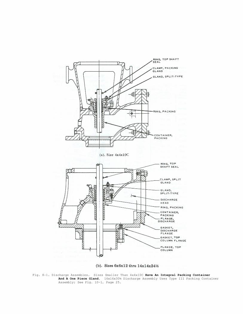
Fig. 8-1. Discharge Assembles. Sizes Smaller Than 4x4x10C Have An Integral Packing Container
And A One Piece Gland. 16x16x30½ Discharge Assembly Uses Type III Packing Container Assembly; See Fig. 10-1, Page 25.

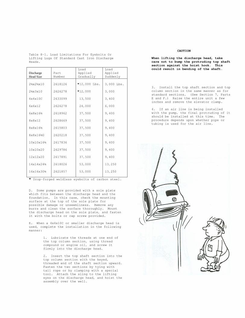
Table 8-1. Load Limitations For Eyebolts Or Lifting Lugs Of Standard Cast Iron Discharge Heads. Discharge Head Size
Part Number
Load Applied Gradually
Load Applied Suddenly
2½x2½x10 2½x3x10 4x4x10C 6x6x12 6x8x16½ 8x8x12 8x8x16½ 8x8x16½G 10x10x16½ 10x10x20 12x12x20 14x14x24½ 16x16x30½
2618126 2626278 2633099 2626278 2618962 2628669 2615803 2620218 2617836 2629786 2617891 2618026 2621857
*12,000 Lbs. *12,000 13,500 24,000 37,500 37,500 37,500 37,500 37,500 37,500 37,500 53,000 53,000
3,000 Lbs. 3,000 3,400 6,000 9,400 9,400 9,400 9,400 9,400 9,400 9,400 13,250 13,250
* Drop-forged weldless eyebolts of carbon steel. D. Some pumps are provided with a sole plate which fits between the discharge head and the foundation. In this case, check the mounting surface at the top of the sole plate for possible damage or unseemliness. Remove any burrs and clean the surface thoroughly. Mount the discharge head on the sole plate, and fasten it with the bolts or cap screw provided. E. When a 4x4x10C or smaller discharge head is used, complete the installation in the following manner:
1. Lubricate the threads at one end of the top column section, using thread compound or engine oil, and screw it firmly into the discharge head. 2. Insert the top shaft section into the top column section with the keyed, threaded end of the shaft section upward. Fasten the two sections by tying with tail rope or by clamping with a special tool. Attach the sling to the lifting eyes on the discharge head, and hoist the assembly over the well.
CAUTION
When lifting the discharge head, take care not to bump the protruding top shaft section against the hoist hook. This could result in bending of the shaft. 3. Install the top shaft section and top column section in the same manner as for standard sections. (See Section 7, Parts E and F.) Raise the entire unit a few inches and remove the elevator clamp. 4. If an air line is being installed with the pump, the final protruding of it should be installed at this time. The procedure depends upon whether pipe or tubing is used for the air line.
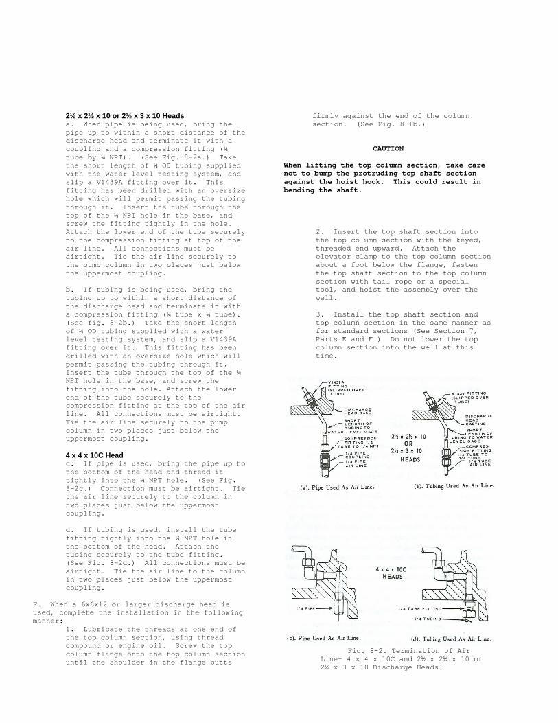
2½ x 2½ x 10 or 2½ x 3 x 10 Heads a. When pipe is being used, bring the pipe up to within a short distance of the discharge head and terminate it with a coupling and a compression fitting (¼ tube by ¼ NPT). (See Fig. 8-2a.) Take the short length of ¼ OD tubing supplied with the water level testing system, and slip a V1439A fitting over it. This fitting has been drilled with an oversize hole which will permit passing the tubing through it. Insert the tube through the top of the ¼ NPT hole in the base, and screw the fitting tightly in the hole. Attach the lower end of the tube securely to the compression fitting at top of the air line. All connections must be airtight. Tie the air line securely to the pump column in two places just below the uppermost coupling. b. If tubing is being used, bring the tubing up to within a short distance of the discharge head and terminate it with a compression fitting (¼ tube x ¼ tube). (See fig. 8-2b.) Take the short length of ¼ OD tubing supplied with a water level testing system, and slip a V1439A fitting over it. This fitting has been drilled with an oversize hole which will permit passing the tubing through it. Insert the tube through the top of the ¼ NPT hole in the base, and screw the fitting into the hole. Attach the lower end of the tube securely to the compression fitting at the top of the air line. All connections must be airtight. Tie the air line securely to the pump column in two places just below the uppermost coupling. 4 x 4 x 10C Head c. If pipe is used, bring the pipe up to the bottom of the head and thread it tightly into the ¼ NPT hole. (See Fig. 8-2c.) Connection must be airtight. Tie the air line securely to the column in two places just below the uppermost coupling. d. If tubing is used, install the tube fitting tightly into the ¼ NPT hole in the bottom of the head. Attach the tubing securely to the tube fitting. (See Fig. 8-2d.) All connections must be airtight. Tie the air line to the column in two places just below the uppermost coupling.
F. When a 6x6x12 or larger discharge head is used, complete the installation in the following manner:
1. Lubricate the threads at one end of the top column section, using thread compound or engine oil. Screw the top column flange onto the top column section until the shoulder in the flange butts
firmly against the end of the column section. (See Fig. 8-1b.)
CAUTION
When lifting the top column section, take care not to bump the protruding top shaft section against the hoist hook. This could result in bending the shaft.
2. Insert the top shaft section into the top column section with the keyed, threaded end upward. Attach the elevator clamp to the top column section about a foot below the flange, fasten the top shaft section to the top column section with tail rope or a special tool, and hoist the assembly over the well. 3. Install the top shaft section and top column section in the same manner as for standard sections (See Section 7, Parts E and F.) Do not lower the top column section into the well at this time.
Fig. 8-2. Termination of Air
Line- 4 x 4 x 10C and 2½ x 2½ x 10 or 2½ x 3 x 10 Discharge Heads.
4. Grease both sides of the top column flange gasket (Fig. 8-1b.) Stick it in place on the lower surface of the discharge head, aligning the air line hole in the discharge head. 5. Install eyebolts in two of the driver mounting holes in the top of the discharge head. Use the hole over the discharge opening and the hole diametrically opposite. Attach the sling to the eyebolts and hoist the assembly over the pump. (The lifting ears are not used to lift the discharge head when not attached to the pump because the discharge head is heavier on the discharge side and would therefore tip.)
CAUTION
When lowering the discharge head to the pump column take care not to bump or scrape the top shaft section protruding above the column. This could result in bending of the shaft.
Lower the discharge head slowly, carefully aligning the central vertical hole in the discharge head with the top shaft so that there will be no bumping or scraping as the shaft enters and passes through the hole. Hold the discharge head at a point just above the top column flange and, if an air line is use, rotate the discharge head as necessary to align the air line hole in the head with a similar hole in the flange. If no air line is being installed, rotate the
discharge head so that the air line holes do not align and will be sealed by the gasket. Continue lowering the discharge head until the studs enter the holes in the top column flange, and the discharge head is firmly seated in place. (See Fig. 8-1b.) Install the hex nuts on the studs to complete installation. Raise the entire unit a few inches, and remove the elevator clamp. 6. If an air line is being installed with the pump, the final portion of it should be installed at this time.
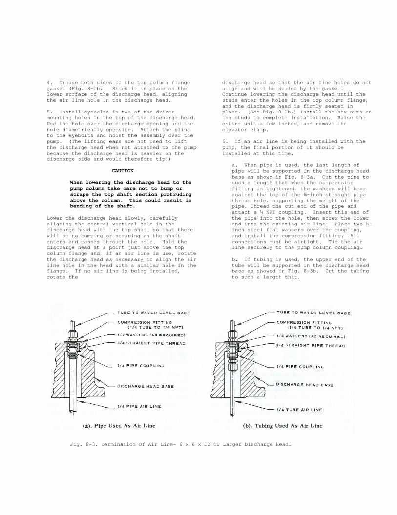
a. When pipe is used, the last length of pipe will be supported in the discharge head base as shown in Fig. 8-3a. Cut the pipe to such a length that when the compression fitting is tightened, the washers will bear against the top of the ¾-inch straight pipe thread hole, supporting the weight of the pipe. Thread the cut end of the pipe and attach a ¼ NPT coupling. Insert this end of the pipe into the hole, then screw the lower end into the existing air line. Place two ½-inch steel flat washers over the coupling, and install the compression fitting. All connections must be airtight. Tie the air line securely to the pump column coupling. b. If tubing is used, the upper end of the tube will be supported in the discharge head base as showed in Fig. 8-3b. Cut the tubing to such a length that,
Fig. 8-3. Termination Of Air Line- 6 x 6 x 12 Or Larger Discharge Head.
