we now learn about the radar hardware basics and then (next week) treat the digital processing of:...
TRANSCRIPT
We now learn about the radar hardware basics and then (next week) treat the digital processing of:
Radar range gating, signal and noise,coherent complex digital sampling,range-time matrix, digital radar data display,coherent integration, coding /decodingcomplex covariance function,complex Doppler spectrum,
parameter deduction.Basics of phased antenna arrays,radiation pattern calculation,radar interferometry and imaging.
Finally a summary of radar methods for atmosphere and ionosphere research and
explanation of some typical results, incl. coherent and incoherent scatter.
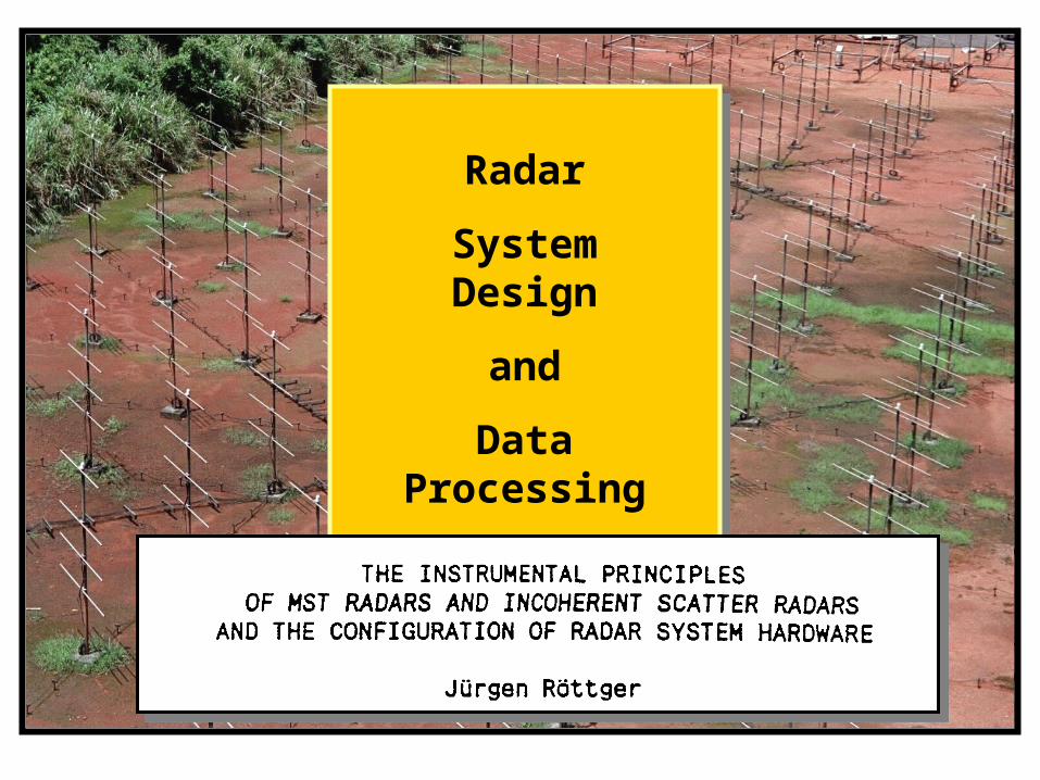
Radar
System Design
and
Data Processing
Radar
System Design
and
Data Processing
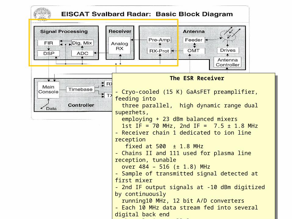
The ESR Receiver
- Cryo-cooled (15 K) GaAsFET preamplifier, feeding into three parallel, high dynamic range dual superhets, employing + 23 dBm balanced mixers 1st IF = 70 MHz, 2nd IF = 7.5 ± 1.8 MHz- Receiver chain 1 dedicated to ion line reception fixed at 500 ± 1.8 MHz- Chains II and 111 used for plasma line reception, tunable over 484 – 516 (± 1.8) MHz- Sample of transmitted signal detected at first mixer- 2nd IF output signals at -10 dBm digitized by continuously running10 MHz, 12 bit A/D converters- Each 10 MHz data stream fed into several digital back end channels in parallel- Detection at nonzero IF results in: DC offset, gain imbalance, quadrature phase errors and unequal filter responses are avoided altogether.- Major advantage over muIti-channel base-band detection system
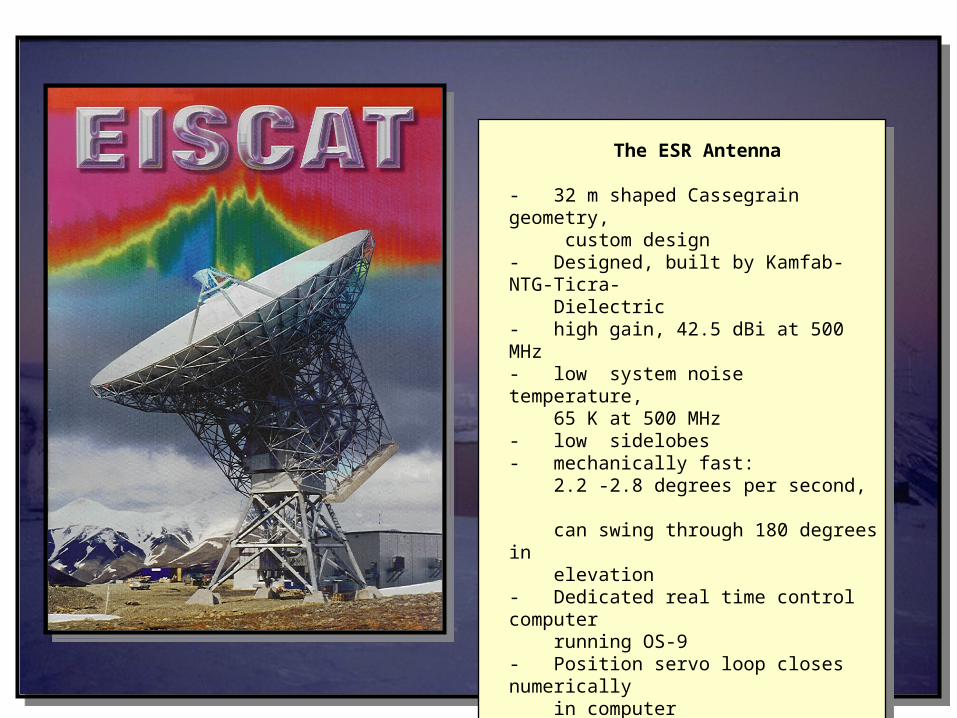
The ESR Antenna
- 32 m shaped Cassegrain geometry, custom design- Designed, built by Kamfab-NTG-Ticra- Dielectric- high gain, 42.5 dBi at 500 MHz- low system noise temperature, 65 K at 500 MHz- low sidelobes- mechanically fast: 2.2 -2.8 degrees per second, can swing through 180 degrees in elevation- Dedicated real time control computer running OS-9- Position servo loop closes numerically in computer
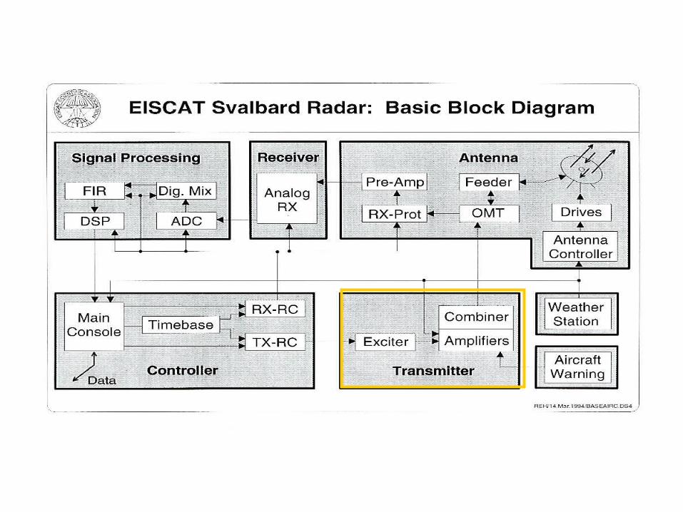
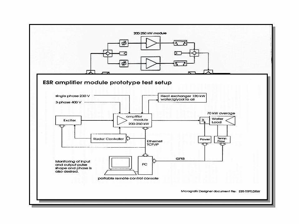
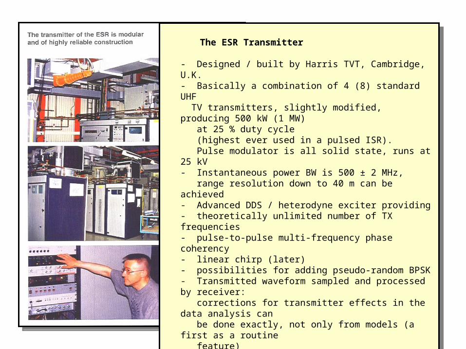
The ESR Transmitter
- Designed / built by Harris TVT, Cambridge, U.K.- Basically a combination of 4 (8) standard UHF TV transmitters, slightly modified, producing 500 kW (1 MW) at 25 % duty cycle (highest ever used in a pulsed ISR). Pulse modulator is all solid state, runs at 25 kV- Instantaneous power BW is 500 ± 2 MHz, range resolution down to 40 m can be achieved- Advanced DDS / heterodyne exciter providing- theoretically unlimited number of TX frequencies- pulse-to-pulse multi-frequency phase coherency- linear chirp (later)- possibilities for adding pseudo-random BPSK- Transmitted waveform sampled and processed by receiver: corrections for transmitter effects in the data analysis can be done exactly, not only from models (a first as a routine feature)- Designed for unattended operation
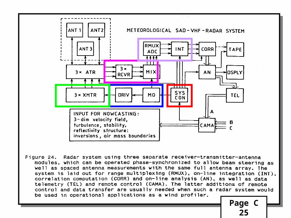
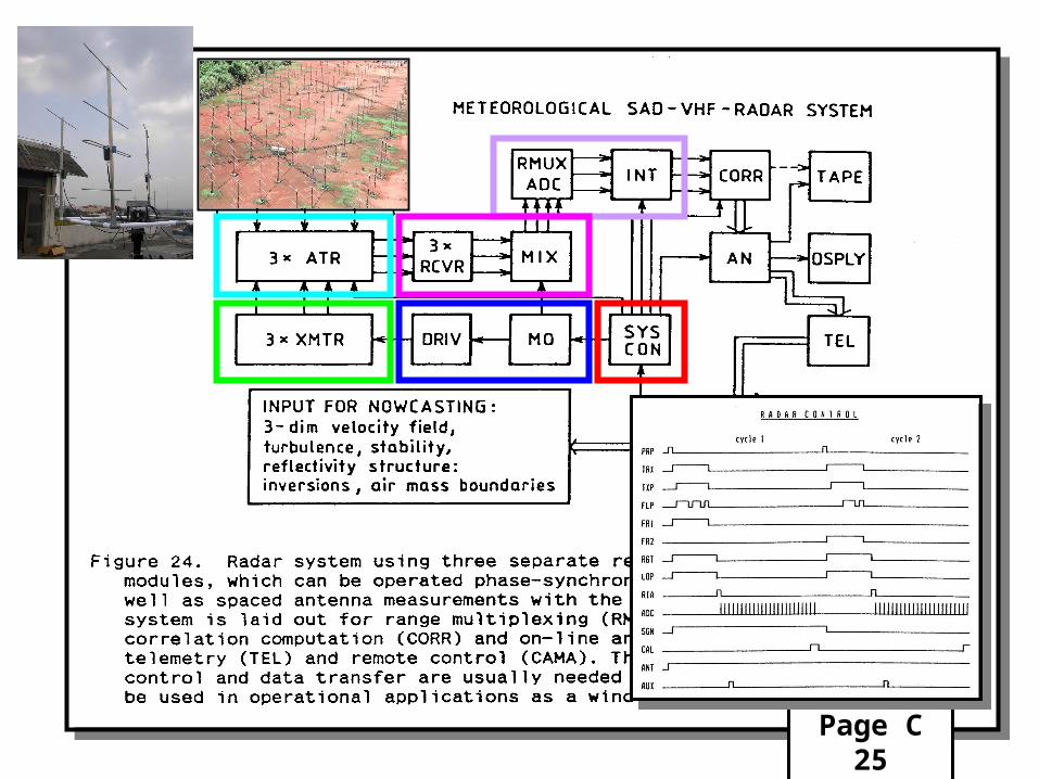
Page C 25
Page C 25

Page C 25
LIMLIM
BL LN MIX BL IFAATTQM
VA
LIM
LPF
LPF
DCLIM
IFA
VA
LIM
BPF
LIM
LIMDC
LIM BL LN MIX BL IFAATT QMVA LPF
LPF
DC IFABPF DC
LIM BL LN MIX BL IFAATT QMVA LPF
LPF
DC IFABPF DC
VA
VA
AMP 1:4 DIV AMP 1:4 DIV
IF MON1
REF (Obtained from MO)
RF IN3
RF IN1
IF MON2
I-2
RF IN2
I-1
Q-3
I-3
IF MON3
Q-1
Q-2
BL SW CONTL
DC SUPPLY
220 Volts AC Mains
AMP120 MHz
OUT
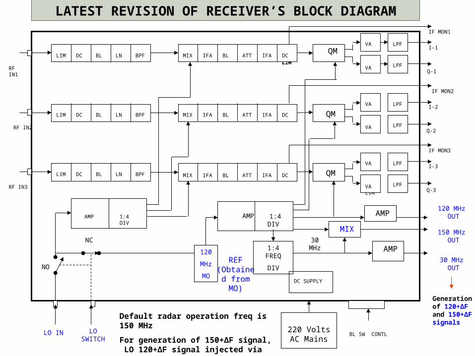
LATEST REVISION OF RECEIVER’S BLOCK DIAGRAM
LO IN
120
MHz
MO
Generation of 120+ΔF and 150+ΔF signals
1:4 FREQ
DIV
MIX
AMP
150 MHz OUT30
MHz
30 MHz OUT
NC
NO
LO SWITCH
Default radar operation freq is 150 MHz
For generation of 150+ΔF signal, LO 120+ΔF signal injected via LO IN
Page C 25
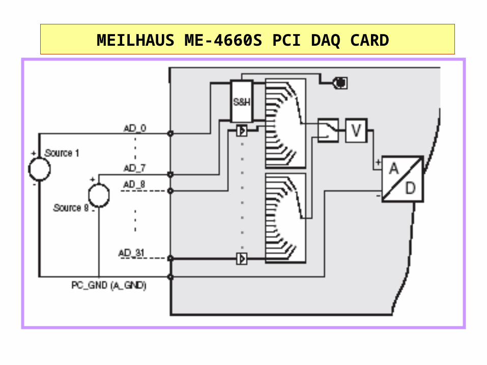
MEILHAUS ME-4660S PCI DAQ CARD
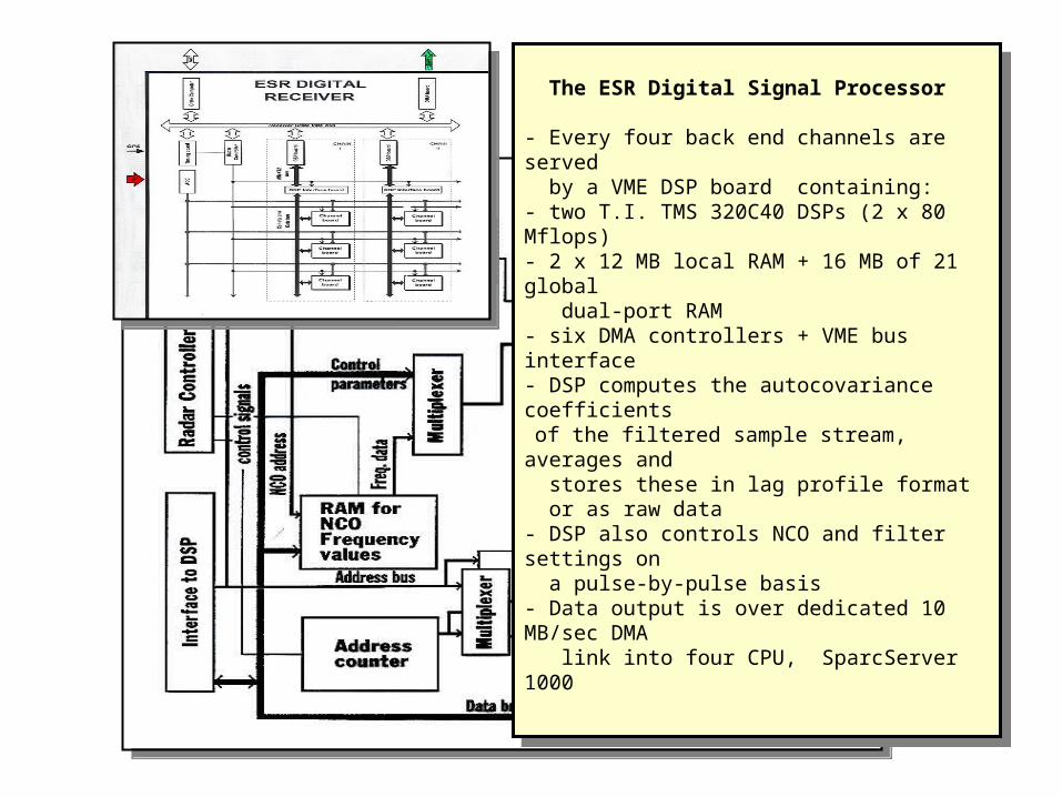
The ESR Digital Signal Processor
- Every four back end channels are served by a VME DSP board containing:- two T.I. TMS 320C40 DSPs (2 x 80 Mflops)- 2 x 12 MB local RAM + 16 MB of 21 global dual-port RAM- six DMA controllers + VME bus interface- DSP computes the autocovariance coefficients of the filtered sample stream, averages and stores these in lag profile format or as raw data- DSP also controls NCO and filter settings on a pulse-by-pulse basis- Data output is over dedicated 10 MB/sec DMA link into four CPU, SparcServer 1000
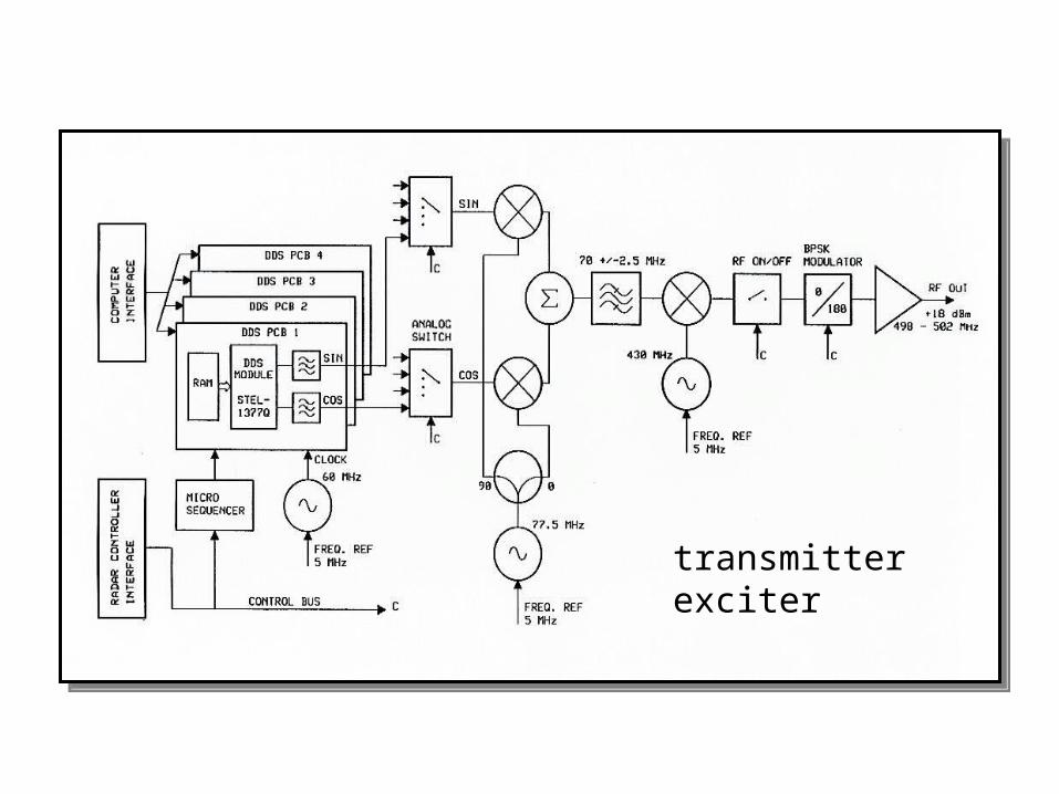
transmitter exciter
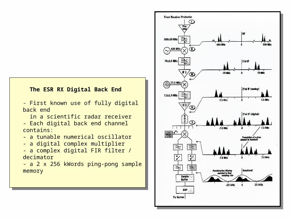
The ESR RX Digital Back End
- First known use of fully digital back end in a scientific radar receiver- Each digital back end channel contains:- a tunable numerical oscillator- a digital complex multiplier- a complex digital FIR filter / decimator- a 2 x 256 kWords ping-pong sample memory
The ESR RX Digital Back End
- First known use of fully digital back end in a scientific radar receiver- Each digital back end channel contains:- a tunable numerical oscillator- a digital complex multiplier- a complex digital FIR filter / decimator- a 2 x 256 kWords ping-pong sample memory
Page C 25
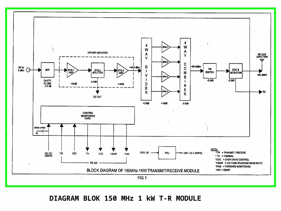
DIAGRAM BLOK 150 MHz 1 kW T-R MODULE
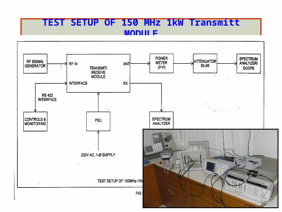
TEST SETUP OF 150 MHz 1kW Transmitt MODULE
Page C 25
Page C 25
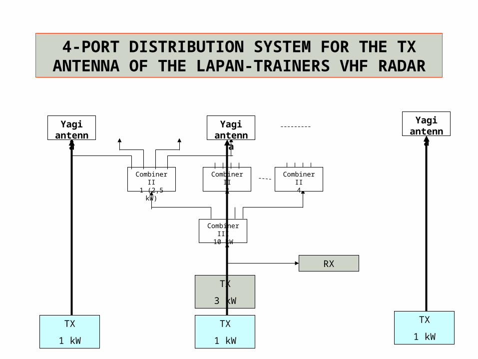
4-PORT DISTRIBUTION SYSTEM FOR THE TX ANTENNA OF THE LAPAN-TRAINERS VHF RADAR
Combiner II1 (2,5 kW)
Combiner II2
Combiner III10 kW
Yagi antenna
Yagi antenna
Yagi antenna
Combiner II4
TX
3 kW
RX
TX
1 kW
TX
1 kW
TX
1 kW
Page C 25
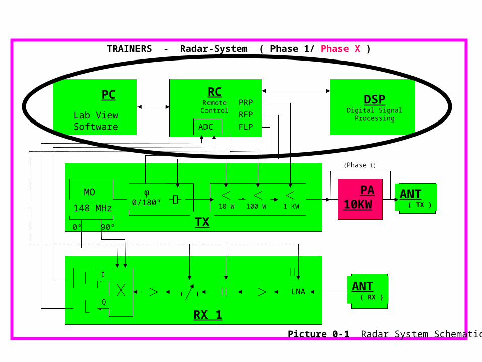
TRAINERS - Radar-System ( Phase 1/ Phase X )
PRP
FLP
RFP
ADC
MO
148 MHz
PC
Lab View Software
RCRemote Control
DSPDigital Signal Processing
TX
PA10KW
ANT ( TX )
ANT ( RX )
RX 1
φ0/180º
0º 90º
10 W 100 W 1 KW
I
Q
LNA
(Phase 1)
Picture 0-1 Radar System Schematic
To follow next: Radar range gating,coherent complex digital sampling,range-time matrix,digital radar data display,coherent integration,complex covariance function,complex Doppler spectrum,parameter deduction.
Basics of phased antenna arrays,pattern calculation,radar interferometry.
A final summary of radar methods for atmosphere and ionosphere research.