jeevamalar.weebly.comjeevamalar.weebly.com/uploads/2/8/9/8/28980229/... · web view1. draw the...
TRANSCRIPT
EDAYATHANGUDY G.S.PILLAY ENGINEERING COLLEGE
NAGAPATTINAM-611002
DEPARTMENT OF MECHANICAL ENGINEERING
M.E. MANUFACTURING ENGINEERING
SECOND SEMESTER
2013 - 2014
MF7211 AUTOMATION AND METAL FORMING LABORATORY
LAB RECORD
NAME : ----------------------------------
REG. NO. : ----------------------------------
EDAYATHANGUDY G.S.PILLAY ENGINEERING COLLEGE
NAGAPATTINAM-611002
BONAFIDE CERTIFICATE
REGISTER NO.: -----------------------------
Certified to be the bonafide record of work done by-----------------------------------,
M.E Manufacturing Engineering II Semester, during the year of 2013-2014.
Head of the Department Staff-in-charge
Submitted for practical examination held in ------------------ at E.G.S. Pillay Engineering College,
Nagapattinam – 611 002.

INTERNAL EXAMINER EXTERNAL EXAMINER
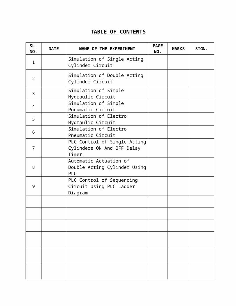
TABLE OF CONTENTS
SL.NO. DATE NAME OF THE EXPERIMENT PAGE
NO. MARKS SIGN.
1 Simulation of Single Acting Cylinder Circuit
2 Simulation of Double Acting Cylinder Circuit
3 Simulation of Simple Hydraulic Circuit
4 Simulation of Simple Pneumatic Circuit
5 Simulation of Electro Hydraulic Circuit
6 Simulation of Electro Pneumatic Circuit
7 PLC Control of Single Acting Cylinders ON And OFF Delay Timer
8 Automatic Actuation of Double Acting Cylinder Using PLC
9 PLC Control of Sequencing Circuit Using PLC Ladder Diagram
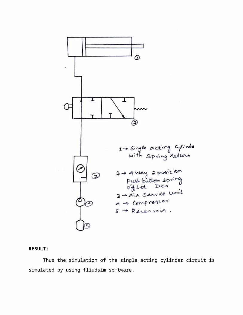
EX.NO: 01 SIMULATION OF SINGLE ACTING CYLINDER CIRCUIT
DATE:
AIM:
To simulate the single acting cylinder circuit by using fliudsim software.
APPARATUS REQUIRED:
1. CPU, Monitor
2. Keyboard and Mouse
3. FLIUDSIM Software
PROCEDURE:
1. Fluid sim software icon is available is the desktop by double clicking the icon.
2. The software home page will open, click new for creating the blank page.
3. Side of the wizard tool is available by using tool use drown the circuit.
4. In the tool symbols, just trag the symbol to the sheet which are the element are
necessary such as (pneumatic –supply element actuator values) compressor, 3/2
mechanically operated spring controlled direction controlled valve and single acting
cylinder.
5. Then correct the ports according to the circuit.
6. Finally simulate by using the simulation tool.

RESULT:
Thus the simulation of the single acting cylinder circuit is simulated by using fliudsim
software.
EX.NO: 02 SIMULATION OF DOUBLE ACTING CYLINDER CIRCUIT
DATE:
AIM:
To simulate the double acting cylinder circuit by using fliudsim software.
APPARATUS REQUIRED:
1. CPU and Monitor
2. Keyboard and Mouse
3. FLIUDSIM Software
PROCEDURE:
1. Fluid sim software icon is available is the desktop by double clicking the icon.
2. The software home page will open, click new for creating the blank page.
3. Side of the wizard tool is available by using tool use drown the circuit.
4. In the tool symbols, just trag the symbol to the sheet which are the element are
necessary such as (pneumatic –supply element actuator values) compressor, 3/2
mechanically operated spring controlled direction controlled valve and single acting
cylinder.
5. Then correct the ports according to the circuit.
6. Finally simulate by using the simulation tool.
RESULT:
Thus the simulation of the double acting cylinder circuit is simulated by using fliudsim
software.
EX.NO: 03 SIMULATION OF SIMPLE HYDRAULIC CIRCUIT
DATE:
AIM:
To simulate the simple hydraulic circuit by using fliudsim software.
APPARATUS REQUIRED:
1. CPU and Monitor
2. Keyboard and Mouse
3. FLIUDSIM Software
PROCEDURE:
1. Fluid sim software icon is available is the desktop by double clicking the icon.
2. The software home page will open, click new for creating the blank page.
3. Side of the wizard tool is available by using tool use drown the circuit.
4. In the tool symbols, just trag the symbol to the sheet which are the element are
necessary such as (simple hydraulic circuit –supply element actuator values) compressor,
3/2 mechanically operated spring controlled direction controlled valve and single acting
cylinder.
5. Then correct the ports according to the circuit.
4. Finally simulate by using the simulation tool.

RESULT:
Thus the simulation of the simple hydraulic circuit is simulated by using fliudsim
software.

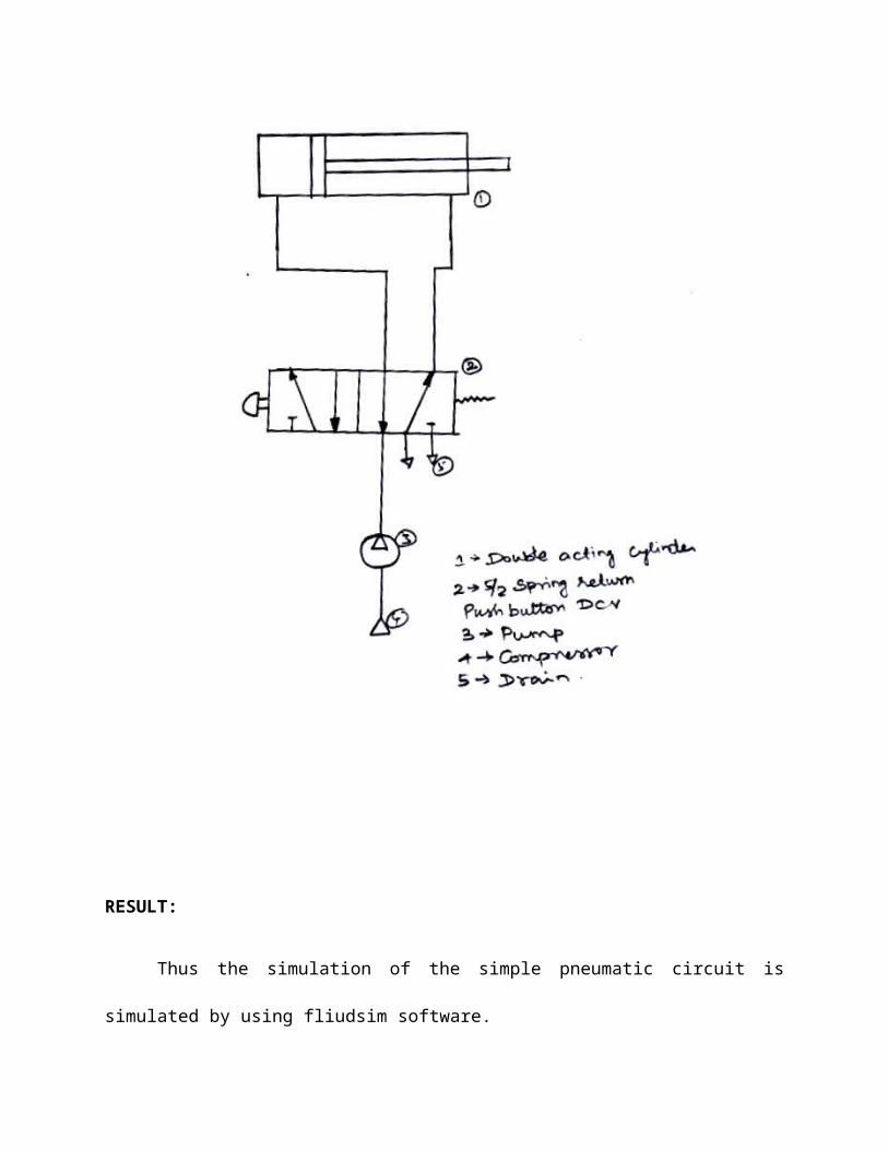
EX.NO: 04 SIMULATION OF SIMPLE PNEUMATIC CIRCUIT
DATE:
AIM:
To simulate the simple pneumatic circuit by using fliudsim software.
APPARATUS REQUIRED:
1. CPU and Monitor
2. Keyboard and Mouse
3. FLIUDSIM Software
PROCEDURE:
1. Fluidsim software icon is available is the desktop by double clicking the icon.
2. The software home page will open, click new for creating the blank page.
3. Side of the wizard tool is available by using tool use drown the circuit.
4. In the tool symbols, just trag the symbol to the sheet which are the element are
necessary such as (pneumatic –supply element actuator values) compressor, 3/2
mechanically operated spring controlled direction controlled valve and single acting
cylinder.
5. Then correct the ports according to the circuit.
6. Finally simulate by using the simulation tool.
RESULT:
Thus the simulation of the simple pneumatic circuit is simulated by using fliudsim
software.

EX.NO: 05 SIMULATION OF ELECTRO HYDRAULIC CIRCUIT
DATE:
AIM:
To simulate the electro hydraulic circuit by using fliudsim software.
APPARATUS REQUIRED:
1. CPU and Monitor
2. Keyboard and Mouse
3. FLIUDSIM Software
PROCEDURE:
1. Fluid sim software icon is available is the desktop by double clicking the icon.
2. The software home page will open, click new for creating the blank page.
3. Side of the wizard tool is available by using tool use drown the circuit.
4. In the tool symbols, just trag the symbol to the sheet which are the element are
necessary such as (hydraulic –supply element actuator values) compressor, 3/2
mechanically operated spring controlled direction controlled valve and single acting
cylinder.
5. Then correct the ports according to the circuit.
6. Finally simulate by using the simulation tool.

RESULT:
Thus the simulation of the electro hydraulic circuit is simulated by using fliudsim
software.

EX.NO: 06 SIMULATION OF ELECTRO PNEUMATIC CIRCUIT
DATE:
AIM:
To simulate the electro pneumatic circuit by using fliudsim software.
APPARATUS REQUIRED:
1. CPU and Monitor
2. Keyboard and Mouse
3. FLIUDSIM Software
PROCEDURE:
1. Fluid sim software icon is available is the desktop by double clicking the icon.
2. The software home page will open, click new for creating the blank page.
3. Side of the wizard tool is available by using tool use drown the circuit.
4. In the tool symbols, just trag the symbol to the sheet which are the element are
necessary such as (pneumatic –supply element actuator values) compressor, 3/2
mechanically operated spring controlled direction controlled valve and single acting
cylinder.
5. Then correct the ports according to the circuit.
6. Finally simulate by using the simulation tool.

RESULT:
Thus the simulation of the electro pneumatic circuit is simulated by using fliudsim
software.
EX.NO: 07 SIMULATION OF ELECTRO PNEUMATIC CIRCUIT
DATE:
AIM:
To design a circuit to extend and retract the single acting cylinder with the help of delay
timer controlled by PLC.
APPARATUS REQUIRED:
1. Single acting cylinder
2. RS 232 cable
3. Versa pro software
4. 3/2 single solenoid valve
5. FRL unit
6. PLC
7. Connecting wires and tube
PROCEDURE:
ON DELAY TIMER:
1. Draw the circuit diagram
2. Provide +24V and –24V from PLC trainer to panel.
3. Open the versa pro software in desktop
4. Interface PLC with PC using RS 232 cable.
5. Write a ladder diagram.
6. Output of PLC (q1) is directly connected to input of solenoid coil.

7. Following the opening procedure of versa pro software.
8. Check the ladder diagram.
9. Connect the air supply to FRL unit.
10. Run the PLC. After some delay the cylinder will be activated.
CIRCUIT DIAGRAM: ON DELAY TIMER

PROCEDURE:
OFF DELAY TIMER
1. Draw the circuit diagram
2. Provide +24V and –24V from PLC trainer to panel.
3. Open the versa pro software in desktop
4. Interface PLC with PC using RS 232 cable.
5. Write a ladder diagram.
6. Output of PLC (q1) is directly connected to input of solenoid coil.
7. Following the opening procedure of versa pro software.
8. Check the ladder diagram.
9. Connect the air supply to FRL unit.
10. Run the PLC and observe the working of single acting cylinder.

CIRCUIT DIAGRAM-OFF DELAY TIMER
RESULT:
Thus the actuation of single acting cylinder with ON and OFF delay timer was done using PLC.

EX.NO: 08 SIMULATION OF ELECTRO PNEUMATIC CIRCUIT
DATE:
AIM:
To simulate the automatic sequence of double acting cylinder using PLC
APPARATUS REQUIRED
1. Double acting cylinder
2. RS 232 cable
3. Versa pro software
4. 5/2 double solenoid valve
5. FRL unit
6. PLC
7. Connecting wires and tube.
PROCEDURE:
1. Draw the circuit diagram
2. Provide +24V and –24V from PLC trainer to panel.
3. Open the versa pro software in desktop
4. Interface PLC with PC using RS 232 cable.
5. Write a ladder diagram.
6. Both outputs of PLC (q1 and q2) are directly connected to inputs of solenoid coils.
7. Following the opening procedure of versa pro software.
8. Check the ladder diagram and connect the air supply to FRL unit
10. Run the PLC and observe the working of double acting cylinder.
CIRCUIT DIAGRAM
RESULT:
Thus the ladder diagram for the automatic running of double acting cylinder is drawn and
executed.

EX.NO: 09 SIMULATION OF ELECTRO PNEUMATIC CIRCUIT
DATE:
AIM:
To design a circuit for the sequence A+B+A-B using PLC.
APPARATUS REQUIRED:
1. Single and double acting cylinder
2. RS 232 cable
3. Versa pro software
4. 3/2 single solenoid valve, 5/2 double solenoid valve
5. FRL unit
6. PLC
7. Connecting wires and tube
PROCEDURE:
1. Draw the circuit diagram
2. Provide +24V and –24V from PLC trainer to panel.
3. Open the versa pro software in desktop
4. Interface PLC with PC using RS 232 cable.
5. Write a ladder diagram.
6. Outputs of PLC (q1, q2, q3 and q4) are directly connected to the inputs of solenoid
coil.
7. Following the opening procedure of versa pro software.
8. Check the ladder diagram.
9. Connect the air supply to FRL unit.
10. Run the PLC and observe the working of double acting cylinder.
CIRCUIT DIAGRAM:
RESULT:
Thus the ladder diagram for the automatic running of double acting cylinders is designed and
executed.