teacher.co.keteacher.co.ke/.../2019/01/physics-booklets-1.docx · web view2019-01-13 · table of...
TRANSCRIPT

TABLE OF CONTENTTOPICS SET RANGE FROM FORM ONE TO FORM FOUR
General questions for practice.................................................…………………………………………..3Measurement I..........................................................................…………………………………….........6Force. .......................................................................................……………………………..……………..Light . ....................................................................................…………………………………………….9Pressure..................................................................................…………………………………………...12Current I..................................................................................………………………………………......12Participate nature of matter....................................................……………………………………………14Thermal expansion...................................................................…………………………………………...Light......................................................................................……………………………….……………15Electrostatics.............................................................................…………………………………………..Measurement II......................................................................……………………………………….........19Turning effect of a force......................................................………………………………………………21Equilibrium and centre of quality.........................................……………………………………………..23Fluid flow.............................................................................……………………………………………...25Hook’s law...........................................................................……………………………………………...27Magnesium............................................................................…………………………………..................27Reflection at curved surfaces................................................……………………………………………..27Linear motion.......................................................................……………………………………………...36Machines & inclined planes..................................................………………………………………….….…Resistors................................................................................…………………………………..................38Newton’s law.........................................................................…………………………………..…………...Circular motion...........................................................................…………………………………...........Refraction of light....................................................................…………………………………………...Sound II................................................................................………………………………………….......42Thin lenses............................................................................……………………………………………...42Quality of heat.......................................................................……………………………..........................42Waves II....................................................................................………………………………………..…Work, energy and power......................................................………………………………….…………..45Floating and sinking............................................................……………………………………………….46Photoelectric effect..................................................................…………………………………………....Electronics..........................................................................………………………………………………...50X-ray. ..................................................................................……………………………………..................50Radioactivity...........................................................................…………………………………………….GM induction.........................................................................…………………………..………………….GM spectrum.............................................................................……………………………….................

GENERAL QUESTIONS FOR PRACTICE1. Suggest one reason why on hot day, heat loses in mains electricity transmission lines may
generally be greater than on a cold day. (1mk)
2. Why is a gap left between one end of a metal bridge and the end of a road leading to
the bridge (1mk)
3. Why does a person weaving dump clothes feel cold on a strong wind (2mks)
4. A bullet of mass 0.8g traveling at 400m/s is stepped by a concrete wall. Calculate the
amount of heat energy transferred to the wall. (2mks)
5. The figure below shows a uniform metre rule on equilibrium.
(i) What is the significance of the word uniform metre rule (1mk)
(ii) Determine the weight of the metre rule (2mks)
6. An object is projected vertically upwards at a speed of 15ms-1. How long will it take to
return to the same level of projection? (3mks)
7. A boy pulls the handle of a lawn mower at an angle of 30o to the horizontal with a force
of 120N. Calculate the work done when the mower moves through a distance of 12.8m. (3mks)
8. State Hooke’s law (1mk)
9. A force of 20N causes a wire to stretch by 40mm. calculate the energy stored on the
100mm wire when stretched 50mm (3mks)
10. State two ways of increasing the strength of an electromagnet (2mks)
11. The diagram shows capacitors in parallel connected to 4V battery
(i) Calculate the total capacitance (2mks)
(ii) What is the energy stored on the capacitors (3mks)
12. Show that a body falling from a height h hits the ground with energy E = ½ mv2 (3mks)
13. (a) State Hooke’s law (1mk)
(b) A force of 50N stretches a spring by 60mm. what force will extend by 20mm (3mks)
(c) Calculate the work required to stretch the spring by 40mm (3mks)
(d) If the diameter of the spring is 14mm, calculate the stress provided when the force
2

of 100N is applied. (3mks)
14. A bullet is fired horizontally from a cliff at a velocity 100ms-1. It takes 10 seconds to
hit the ground.
(i) Sketch the graph of height against time for the motion (2mks)
(ii) Calculate the height of the cliff (2mks)
(iii) What is the horizontal distance moved form the cliff when the bullet hits the ground (3mks)
(iv) Determine the velocity and direction with which the bullet hits the ground (3mks)
15. A crane lifts a load of 2000kg though a vertical distance of 3.0m in 6 seconds.
(a) Determine the ;
(i) Work done (2mks)
(ii) Power developed by the crane (2mks)
(iii) Efficiency of the crane given that it is operated by an electric motor rated 12.5Kw
(b) In an experiment to determine the specific latent heat of vaporization of matter, steam
at 100oC was passed into water contained in a well lagged copper calorimeter. The
following results were made:
Mass of calorimeter = 50g
Initial mass of water= 70g
Initial temperature of water = 5oC
Final mass of calorimeter + condensed steam = 123g
Final temperature of mixture = 30o
Specific heat capacity f water = 5200JKg-1K-1 and specific heat capacity for copper = 390JKg-1U-1)
Determine the; (a) Mass of condensed steam (1mk)
(b) Heat gained by the calorimeter (4mks)
(c) Specific latent heat of vaporization of steam (3mks)
16. Distinguish between soft and hard magnetic materials (2mks)
17. (a) Define the following terms ; (i) Mechanical advantage
(ii) Velocity ration
(iii) Efficiency
(b) Draw a diagram of a pulley system having ;
(i) Velocity ratio of 5 (3mks)
(ii) The pulley system above is used to raise a lead of 100N through a distance of 5cm.
The system is 80% efficient.
Calculate; (i) The effort (4mks)
(ii) The work done (3mks)
3
18. (a) State the principle of moments (1mk)
(b) A uniform plan of length 6m is pivoted at the centre to make a see saw. A weight of
200N acts at one end. A body weighing 500N moves towards the pivot on the plank as shown.
How far will the boy have to move from the pivot, for the see-saw to balance? (3mks)
19. A string vest keeps a person warm though it is a collection of holes bounded by strings. Explain (2mks)
20. Which property of waves explains why sounds are easier t hear at night (1mk)
21. Three resistors are connected as shown at the figure below.
Determine the potential difference between A and B (3mks)
22. A wise cyclist will carry a load on the bicycle’s carrier and not in a rack sack on his
back. Explain
(2mks)
23. Give a reason why tungsten is performed as target material in the X-ray tube. (1mk)
24. An object weighs 0.56N in air and 0.42N when wholly immersed in water. Calculate
the density of the object. (Density of water = 1x10³kgm-3) (3mks)
25. The conductivity of a metallic conductor decreases with increase in temperature whereas
the conductivity of a semi-conductor increases with increase in temperature. Explain (2mks)
26. Light of frequency 6.0x 10¹⁴Hz strikes a sodium surface of work function 3.68 x 10⁻¹⁹J.
Calculate the maximum energy with which electrons are emitted. (Planks constant = 6.6 x 10⁻³⁴J) (3mks)
27. Use the kinetic theory to explain the behavior of illuminated smoke floating in air (2mks)
29. Find the quantity of heat required to change ice at -10oC to water at 0oC (3mks)
30. The pattern below shows oil leakage on a path at the rate of 10drops per second form a lorry.
4

(a) Calculate the initial and final velocity (3mks)
(b) Calculate the acceleration of the lorry (2mks)
SECTION 1 – QUESTIONSMeasurement I
1. (a) Distinguish between density and relative density of a substance (b) A ship of mass 1300 tonnes floats on sea water: (i) What volume of sea water is displaced (Density of sea water is 1025kg/m3) (ii) Suppose it sails from sea water to fresh water, what cargo must be removed so that the same volume of water is displaced?(Density of fresh water = 1000kg/m3
(c) Describe an experiment to verify the law of floatation2. Define relative density3. A bathroom shower has 200 holes each 2.5mm2 in area. Water flows from a pipe of cross-section area of 15cm2 at 5m/s to the shower. Determine the speed of the spray.4. A piece of metal N of mass 2kg weighs 18N in water and 12N in liquid M. Determine the density
of ; (i) The metal N (ii) The liquid M 5. A measuring cylinder contains 50cm3 of light oil at 0oC. When a lump of dried ice is placed in the oil, the total volume is 72cm3. Determine the density of the ice
The figure 1 below shows a manometer connected to a gas supply. The pressure of the gas supply above the atmospheric pressure is equivalent to a 20cm column of water. Use this information and the figure to answer questions 2 and 3.
Force1. (a) The figure below shows a balloon carrying hydrogen gas 3m3 of density 0.09kgm-3. The mass of the balloon fabric is 2kg and the density of air is 1.25kgm-3
i) Determine the tension in the string ii) If the string is suddenly cut, calculate the acceleration of the balloon upwards iii) What is the maximum mass of the equipment the balloon can lift at a constant velocity b) State and explain two features of a hydrometer that make it sensitive in its function
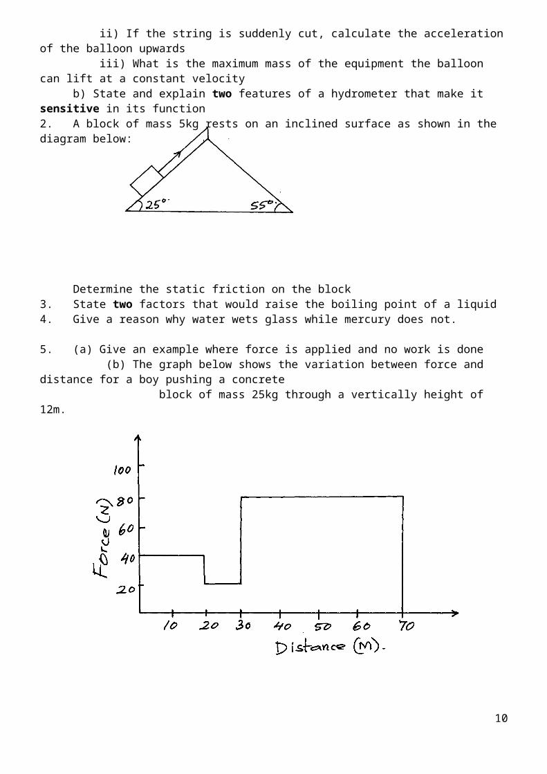
2. A block of mass 5kg rests on an inclined surface as shown in the diagram below:
5

Determine the static friction on the block3. State two factors that would raise the boiling point of a liquid4. Give a reason why water wets glass while mercury does not.5. (a) Give an example where force is applied and no work is done (b) The graph below shows the variation between force and distance for a boy pushing a concrete block of mass 25kg through a vertically height of 12m.
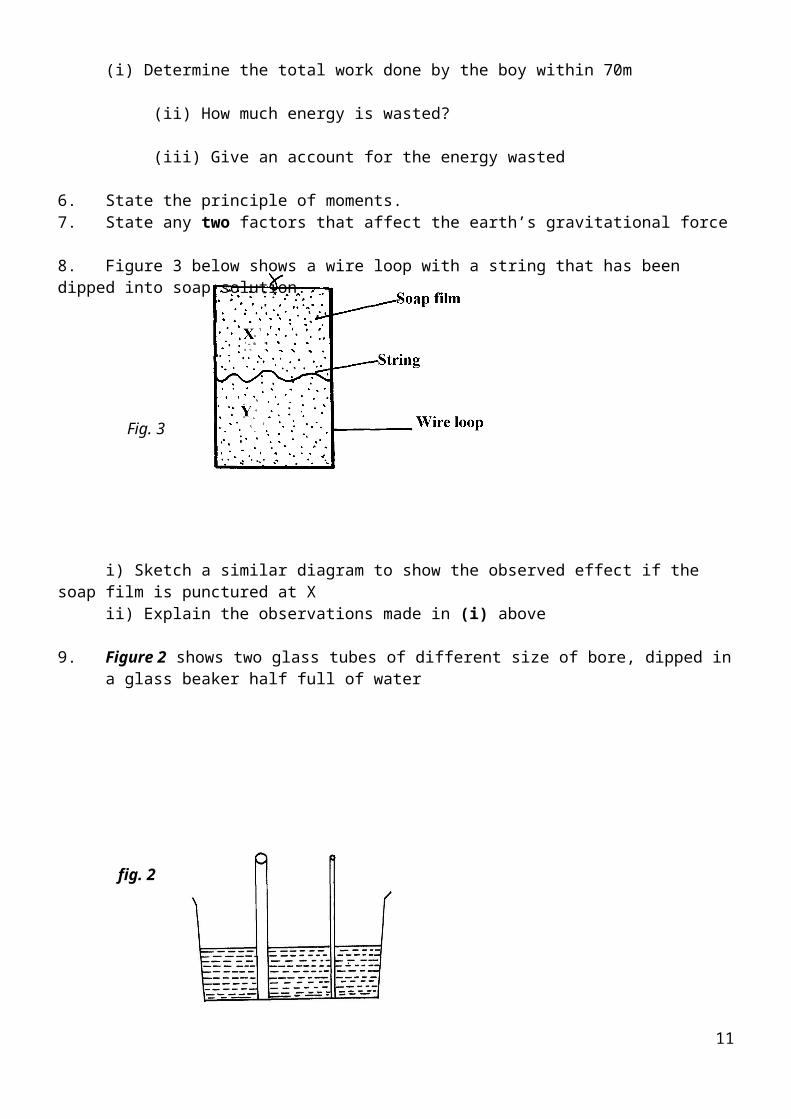
(i) Determine the total work done by the boy within 70m (ii) How much energy is wasted? (iii) Give an account for the energy wasted6. State the principle of moments.7. State any two factors that affect the earth’s gravitational force8. Figure 3 below shows a wire loop with a string that has been dipped into soap solution.
i) Sketch a similar diagram to show the observed effect if the soap film is punctured at Xii) Explain the observations made in (i) above
9. Figure 2 shows two glass tubes of different size of bore, dipped in a glass beaker half full of wa-ter
6
Fig. 3
fig. 2
Complete the diagram to show how water will rise up in the two glass tubes
10. (a) State the conditions necessary for the law of conservation of linear momentum to hold(b) The diagram figure 13 below shows a steel ball bearing gently dipped in a viscous liquid contained in a tall cylinder
fig. 13
(i) Name giving their directions the forces acting on the ball bearing as it moves down the cylinder (ii) The graph in figure 14 below shows the velocity-time graph (a) for the motion of the above ball
fig. 14.
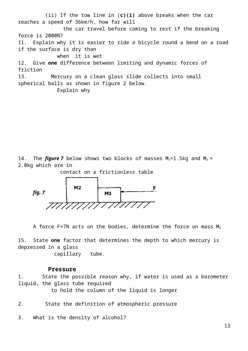
On the same diagram, draw the graph (b) for a steel ball of smaller radius in the same liquid (iii) Explain the difference in the two graphs (a) and (b) (c) (i) A breakdown truck tows a car of mass 1000kg along a level road, and accelerates at 0.5m/s2. What is the tension in the tow line (ii) If the tow line in (c)(i) above breaks when the car reaches a speed of 36km/h, how far will the car travel before coming to rest if the breaking force is 2000N?11. Explain why it is easier to ride a bicycle round a bend on a road if the surface is dry than when it is wet12. Give one difference between limiting and dynamic forces of friction13. Mercury on a clean glass slide collects into small spherical balls as shown in figure 2 below. Explain why
7

Pith balls
14. The figure 7 below shows two blocks of masses M1=1.5kg and M2 = 2.0kg which are in contact on a frictionless table
fig. 7
A force F=7N acts on the bodies, determine the force on mass M2
15. State one factor that determines the depth to which mercury is depressed in a glass capillary tube.
Pressure 1. State the possible reason why, if water is used as a barometer liquid, the glass tube required to hold the column of the liquid is longer2. State the definition of atmospheric pressure3. What is the density of alcohol?4. A person’s lung pressure as recorded by a mercury manometer is 90 mm Hg. Express this
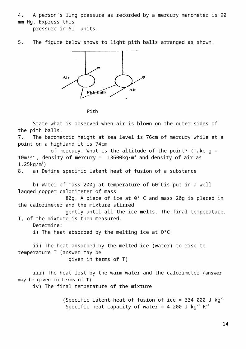
pressure in SI units.5. The figure below shows to light pith balls arranged as shown.
State what is observed when air is blown on the outer sides of the pith balls.7. The barometric height at sea level is 76cm of mercury while at a point on a highland it is 74cm of mercury. What is the altitude of the point? (Take g = 10m/s2 , density of mercury =
13600kg/m3 and density of air as 1.25kg/m3)8. a) Define specific latent heat of fusion of a substance
b) Water of mass 200g at temperature of 60°Cis put in a well lagged copper calorimeter of mass 80g. A piece of ice at 0° C and mass 20g is placed in the calorimeter and the mixture stirred gently until all the ice melts. The final temperature, T, of the mixture is then measured.
Determine:i) The heat absorbed by the melting ice at O°Cii) The heat absorbed by the melted ice (water) to rise to temperature T (answer may be
given in terms of T)
8
iii) The heat lost by the warm water and the calorimeter (answer may be given in terms of T)iv) The final temperature of the mixture
(Specific latent heat of fusion of ice = 334 000 J kg-1
Specific heat capacity of water = 4 200 J kg-1 K-1
Specific heat capacity of copper = 900J kg-1 K-1) 9. Figure 4 below shows a measuring cylinder of height 30cm filled to a height of 20cm with
water and the rest occupied by kerosene
Given that density of water = 1000Kgm-3, density of kerosene = 800Kgm-3 and atmospheric pressure = 1.03x10⁵ pascals, determine the pressure acting on the base of the container
10. State Pascal’s principle of transmission of pressure11. A helical spring extends by 1 cm when a force of 1.5N is applied to it. Find the elastic potential
energy stored in it.12. Two immiscible liquids are poured in a container to the levels shown in the diagram below.
If the densities of the liquids A and B are 1g/cm3 and 0.8g/cm3 respectively, find the pressure acting upon solid C at the bottom of the container due to the liquids
13. Mark the position of the water levels in the manometer when the gas supply is fully turned on 14. Calculate the pressure of the gas supply (Atmospheric pressure = 1.0x10⁵Pa)
15. A small nail may pierce an inflated car tyre and remain there without pressure reduction in the tyre. Explain the observation16. (a) State two ways of increasing pressure in solids
9
Figure 5
figure 1
Fig. 4
(b) The figure 1 shows a liquid in a pail
Suggest a reason why pail manufacturers prefer the shape shown to other shapes17. Figure 8 shows a funnel inverted over a light ball.
fig. 8
Explain the observation that would be made when streamlines of air is blown strongly down the narrow section of the funnel
18. A block measuring 20cm x 10cm by 5cm rests on a flat surface. The block has a weight of 3N. Determine the maximum pressure it exerts on the surface.19. The figure below shows a hydraulic press P which is used to raise a load of 10KN. A force F of 25N is applied at the end of a lever pivoted at O to raise the load
(a) State one property of liquid X (b) Determine the distance x indicated on the press if force on piston B is 100N19. A mercury –in-glass barometer shows a height of 70cm. What height would be shown in the
barometer at the same place if water density 1.0 x 10³kg/m3 is used. (Density of mercury = 13600kgm-3) 20. The total weight of a car with passengers is 25,000N. The area of contact of each of the four tyres with the ground is 0.025m2. Determine the minimum car tyre pressure 21. (a) The diagram below represents a u-shaped glass tube sealed at one end and containing mercury
10
fig. 1
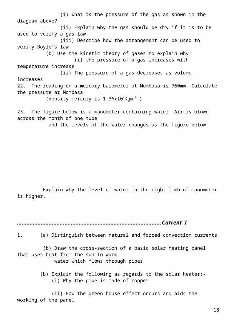
(i) What is the pressure of the gas as shown in the diagram above? (ii) Explain why the gas should be dry if it is to be used to verify a gas law (iii) Describe how the arrangement can be used to verify Boyle’s law. (b) Use the kinetic theory of gases to explain why; (i) the pressure of a gas increases with temperature increase (ii) The pressure of a gas decreases as volume increases22. The reading on a mercury barometer at Mombasa is 760mm. Calculate the pressure at Mombasa (density mercury is 1.36xl04Kgm-3 ) 23. The figure below is a manometer containing water. Air is blown across the month of one tube and the levels of the water changes as the figure below.
Explain why the level of water in the right limb of manometer is higher.
........................................................................................................Current I
1. (a) Distinguish between natural and forced convection currents (b) Draw the cross-section of a basic solar heating panel that uses heat from the sun to warm water which flows through pipes (b) Explain the following as regards to the solar heater:- (i) Why the pipe is made of copper (ii) How the green house effect occurs and aids the working of the panel2. State two advantages of generating an alternating current (a.c) to direct current (d.c) in a power station.3. The table below shows results obtained in an experiment to determine the internal resistance
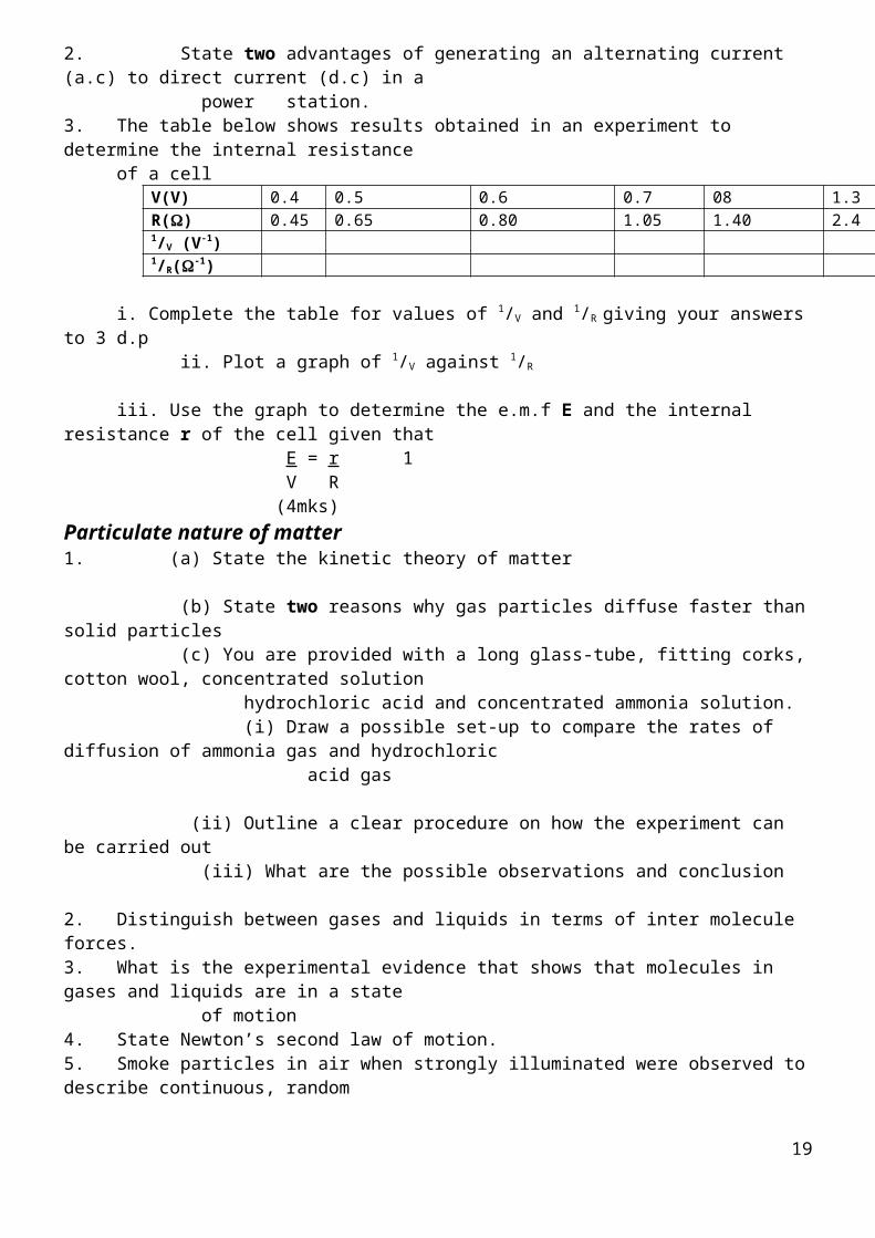
of a cellV(V) 0.4 0.5 0.6 0.7 08 1.3R(W) 0.45 0.65 0.80 1.05 1.40 2.41/V (V-1)1/R(W-1)
i. Complete the table for values of 1/V and 1/R giving your answers to 3 d.p ii. Plot a graph of 1/V against 1/R
iii. Use the graph to determine the e.m.f E and the internal resistance r of the cell given that E = r 1 V R (4mks)Particulate nature of matter1. (a) State the kinetic theory of matter (b) State two reasons why gas particles diffuse faster than solid particles (c) You are provided with a long glass-tube, fitting corks, cotton wool, concentrated solution hydrochloric acid and concentrated ammonia solution. (i) Draw a possible set-up to compare the rates of diffusion of ammonia gas and hydrochloric acid gas
11

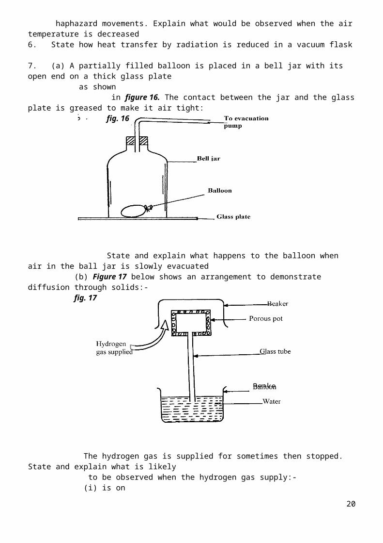
(ii) Outline a clear procedure on how the experiment can be carried out (iii) What are the possible observations and conclusion2. Distinguish between gases and liquids in terms of inter molecule forces.3. What is the experimental evidence that shows that molecules in gases and liquids are in a state of motion4. State Newton’s second law of motion.5. Smoke particles in air when strongly illuminated were observed to describe continuous, random haphazard movements. Explain what would be observed when the air temperature is decreased 6. State how heat transfer by radiation is reduced in a vacuum flask7. (a) A partially filled balloon is placed in a bell jar with its open end on a thick glass plate
as shown in figure 16. The contact between the jar and the glass plate is greased to make it air tight: fig. 16
State and explain what happens to the balloon when air in the ball jar is slowly evacuated (b) Figure 17 below shows an arrangement to demonstrate diffusion through solids:- fig. 17
The hydrogen gas is supplied for sometimes then stopped. State and explain what is likely to be observed when the hydrogen gas supply:- (i) is on (ii) is stopped (c) The diagram fig. 18 shows a glass tube containing enclosed air by a thread of mercury 50mm long when the tube is held in a horizontal position
fig. 18
12
Beaker
Mercury thread
Trapped air
(i) The tube is slowly raised in a vertical position with the open end facing up. Determine the new length of the trapped air (tube has same area of cross-section; atmospheric
pressure = 750mmHg) (ii) Account for the difference in the column of trapped air using kinetic theory of matter assuming that temperature is constant.8. Two samples of bromine vapour are allowed to diffuse separately under different conditions, one in a vacuum and the other in air. State with reasons the conditions in which bromine will diffuse faster9. In terms of kinetic theory of matter, explain why evaporation causes cooling10. (a) In an experiment to demonstrate Brownian motion, smoke was placed in air cell and observed under a microscope. Smoke particles were observed to move randomly in the cell. (i) Explain the observation (ii) Give a reason for using small particles such as those of smoke in this experiment (iii) What would be the most likely observation if the temperature in the smoke cell was raised? (b) An oil drop of average diameter 0.7mm spreads out into a circular patch of diameter 75cm on the surface of water in a trough (i) Calculate the average thickness of a molecule of oil (ii) State two assumptions made in (i) above 11. Give a reason why gases are more compressible than liquids12. Explain the cause of random motion of smoke particles as observed in Brownian motion experiment using a smoke cell.
Thermal expansion
1. Figure 1 shows a beam balance made out of concrete and reinforced with steel
Use a diagram to explain the behaviour of the shape of the beam when heated up
2. (a) Sate two liquids which are used in thermometer.
(b) With a reason, state which of the two liquids in 3 (a) above is used to measure temperature in areas where temperatures are:
. (i) below -400c (ii) 1500c3. What do you understand by the statement ‘lower fixed point’ on a temperature scale?4. Name two adaptations that can be made to a mercury thermometer to make it more sensitive5. Figure 5 shows a bimetallic strip made of brass and iron. A marble is placed at end A of the
bimetallic strip as shown below:-
fig. 5
State and explain what will be observed when the bimetallic strip is strongly cooled
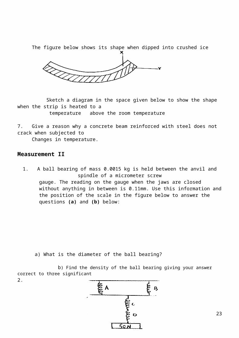
6. The figure below represents a bimetallic strip of metals X and Y at room temperature
13
The figure below shows its shape when dipped into crushed ice
Sketch a diagram in the space given below to show the shape when the strip is heated to a temperature above the room temperature
7. Give a reason why a concrete beam reinforced with steel does not crack when subjected to Changes in temperature.
Measurement II
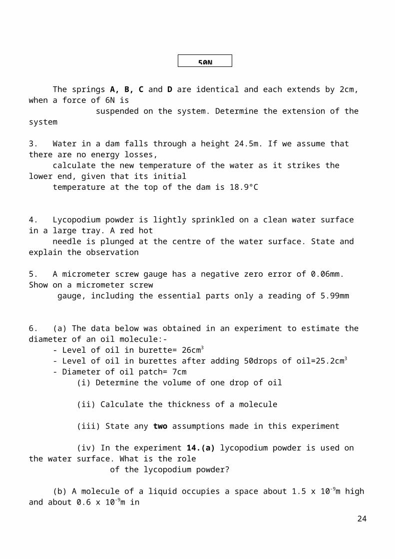
1. A ball bearing of mass 0.0015 kg is held between the anvil and spindle of a micrometer screw gauge. The reading on the gauge when the jaws are closed without anything in between is 0.11mm. Use this information and the position of the scale in the figure below to answer the questions (a) and (b) below:
a) What is the diameter of the ball bearing? b) Find the density of the ball bearing giving your answer correct to three significant 2.
The springs A, B, C and D are identical and each extends by 2cm, when a force of 6N is suspended on the system. Determine the extension of the system
3. Water in a dam falls through a height 24.5m. If we assume that there are no energy losses, calculate the new temperature of the water as it strikes the lower end, given that its initial temperature at the top of the dam is 18.9°C
4. Lycopodium powder is lightly sprinkled on a clean water surface in a large tray. A red hot needle is plunged at the centre of the water surface. State and explain the observation
14
50N

5. A micrometer screw gauge has a negative zero error of 0.06mm. Show on a micrometer screw gauge, including the essential parts only a reading of 5.99mm
6. (a) The data below was obtained in an experiment to estimate the diameter of an oil molecule:-- Level of oil in burette= 26cm3
- Level of oil in burettes after adding 50drops of oil=25.2cm3
- Diameter of oil patch= 7cm (i) Determine the volume of one drop of oil (ii) Calculate the thickness of a molecule (iii) State any two assumptions made in this experiment (iv) In the experiment 14.(a) lycopodium powder is used on the water surface. What is the role of the lycopodium powder?
(b) A molecule of a liquid occupies a space about 1.5 x 10⁻⁹m high and about 0.6 x 10⁻⁹m in thickness and breadth. Calculate the number of molecules in a litre of the liquid
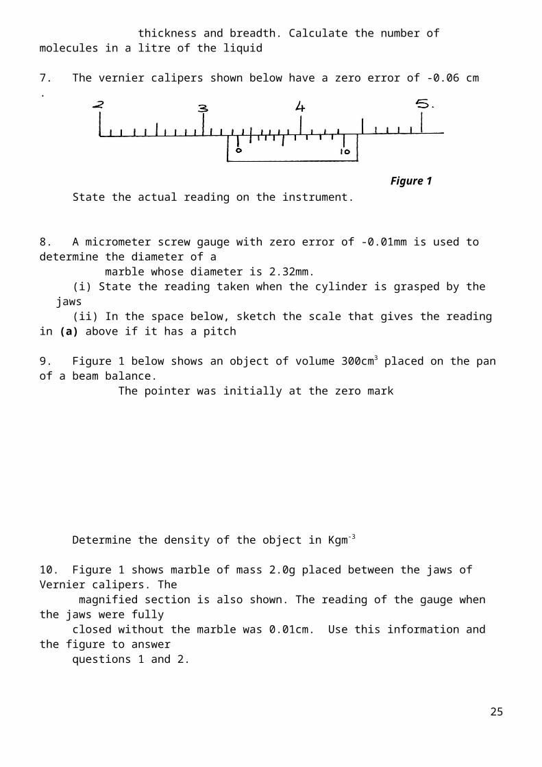
7. The vernier calipers shown below have a zero error of -0.06 cm.
State the actual reading on the instrument.
8. A micrometer screw gauge with zero error of -0.01mm is used to determine the diameter of a marble whose diameter is 2.32mm.
(i) State the reading taken when the cylinder is grasped by the jaws(ii) In the space below, sketch the scale that gives the reading in (a) above if it has a pitch
9. Figure 1 below shows an object of volume 300cm3 placed on the pan of a beam balance. The pointer was initially at the zero mark
Determine the density of the object in Kgm-3
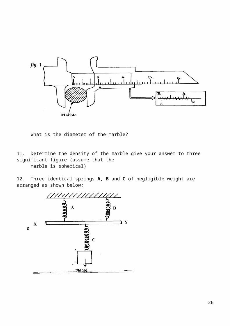
10. Figure 1 shows marble of mass 2.0g placed between the jaws of Vernier calipers. The magnified section is also shown. The reading of the gauge when the jaws were fully closed without the marble was 0.01cm. Use this information and the figure to answer questions 1 and 2.
15
Figure 1
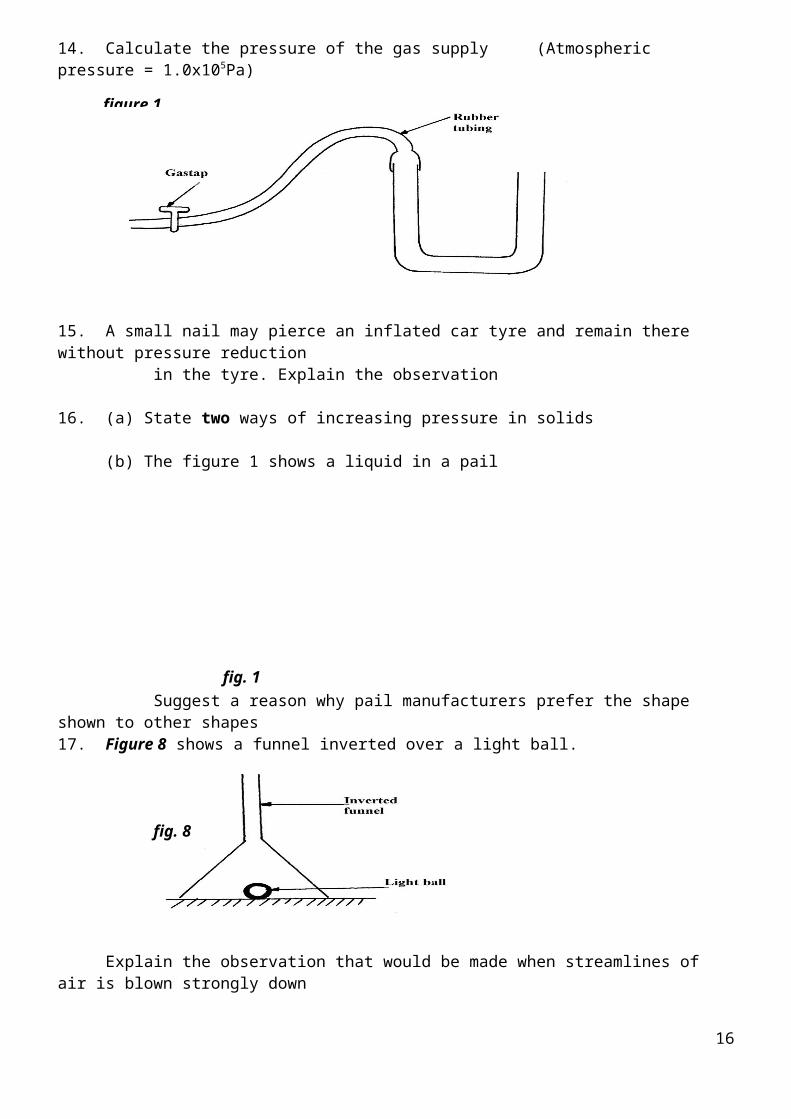
fig. 1
What is the diameter of the marble?
11. Determine the density of the marble give your answer to three significant figure (assume that the marble is spherical)
12. Three identical springs A, B and C of negligible weight are arranged as shown below;
If C stretches by 3cm, and bar XY is assumed to be weightless, determine the extension in A
13. When a drop of olive oil of radius 1.36mm is placed on the surface of water, it spreads out to form a circular film of diameter 40cm. Calculate; (a) The volume of the olive oil drop in m3 (Take p = 22/7) (b) Using the value of (a) above, estimate the thickness of the film. (c) Explain why lycopodium powder is sprinkled on the surface of water before the oil is dropped on it. (d) State two assumptions made when finding the thickness of the film formed.
14. Figure (a) Shows vernier calipers with the jaws completely closed while (b) shows the same vernier calipers in use
Determine the actual diameter of the coin
16
X
2N

15. Give the reading on the micrometer screw gauge if it has a positive zero error of 0.01mm
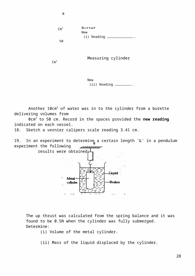
16. Draw a sketch of a micrometer screw gauge showing a reading of 8.53mm. 17. The figure below shows a measuring cylinder containing some water.
Another 10cm3 of water was in to the cylinder from a burette delivering volumes from 0cm3 to 50 cm. Record in the spaces provided the new reading indicated on each vessel.
18. Sketch a vernier calipers scale reading 3.41 cm. 19. In an experiment to determine a certain length ‘L’ in a pendulum experiment the following results were obtained:
The up thrust was calculated from the spring balance and it was found to be 0.5N when the cylin-der was fully submerged. Determine:
(i) Volume of the metal cylinder. (ii) Mass of the liquid displaced by the cylinder. (iii) Density of the liquid
17
0
Cm3 Burrette New (i) Reading …………………………………..
50
Measuring cylinder
New (ii) Reading ……………………..
Cm3
F1 40cm
Metre rule
String F2 = 5N
Pulley
20. The figure below shows a scale of part of venier caliper
State the correct reading of the scale if the instrument has a zero error of -0.02cm.
Turning effect of a force
1. Figure 4 below shows a uniform metre rule in equilibrium under the forces shown
Determine the weight of the metre rule2. The diagram below shows a uniform meter rule of mass 300g balanced by two forces F1 and F2. Force F2 is 5N. Assuming there is no frictional force on the pulleys,
Calculate the force F1
3. (a) The figure below shows a system in equilibrium at room temperature. The system is taken outside where the temperature is 20oC higher for sometime.
Explain why it tips to the right when it is taken outside the room. (c) (i) State the law of floatation.
(ii) The fig. below shows a floating object of volume 40,000 cm3 and mass 10g. It is held as shown in water of density 1.25g/cm3 by a light cable at the bottom so that ¾ of the volume
18
Figure 9
9 cm10
0 10
of the object is below the water surface. (Assume that up thrust due to air is negligible)
(iii) (I) Calculate the volume of the object under water. * (II) State the volume of water displaced by the object.
(III) Calculate the weight of water displaced.(iv) Determine the tension in the cable
(v) Calculate the density of the object.4. State the principle of moments.5. Figure 4 shows a uniform wooden plank which weighs 10N. The plank is balanced at 0.8m
from one end by a mass of 2.5kg
What is the length of the wooden plank in metres?6. Figure 4 shows a uniform rod AE which is 40cm long. It has a mass of 2kg and pivoted at D. If
2N is acting at point E, and 30N force is passed through a frictionless pulley
fig 4
Find the force (x) acting at end A
7. A uniform half metre long beam, pivoted at the 10cm mark, balances when a mass of 150g is sus-pended at the 0cm mark as shown below:
19
Figure 11
fig. 4
X
Calculate the weight of the beam 8. The figure below shows a ring of a thin steel washer.
Determine the centre of gravity of the washer.
9. The diagram below shows a uniform metre rule balanced by two forces A and B. If force B is 5N, assuming that there no frictional force on the fixed pulley, calculate the weight of the metre rule.
Equilibrium and centre of gravity1. a) Define centre of gravity
b) The figure below shows a wine glass
State how the stability of the glass is affected if it is filled with wine 2. The diagram below shows an empty wine glass.
State and explain the effect on its stability when wine is put into the glass.3. State two ways in which stability of a body can be increased4. In the set up in figure 5, the metre rule is in equilibrium
20
Figure 3
String 40cm
A, 50g
30o
B
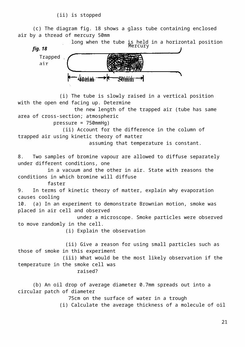
Fig. 5
Given that the metre rule is uniform, determine its weight
5. Figure 6 shows a spring coin which tends to remain vertical but topples immediately it stops spinning
fig. 6
Explain this observation
6. In the thin triangular laminar ABC shown in figure below, determine geometrically the centre of gravity
7. A uniform metre rule is balanced at its centre. It is balanced by the 30N, 5N and the magnetic force between P and Q. P is fixed and Q has a weight of 5N
Ignoring the weight of the metre rule, calculate the value of the magnetic force between Q and P8. (a) Use simple sketches to show the three states of equilibrium. Name the states. (b) Define center of gravity of a body. (c) State two factors affecting stability of body (d) The figure below shows a metal plate 2 m long, 1M wide and negligible thickness. A horizontal force of 50 n applied at point ‘A’ Just makes the plate tilt.
21
Direction of spin
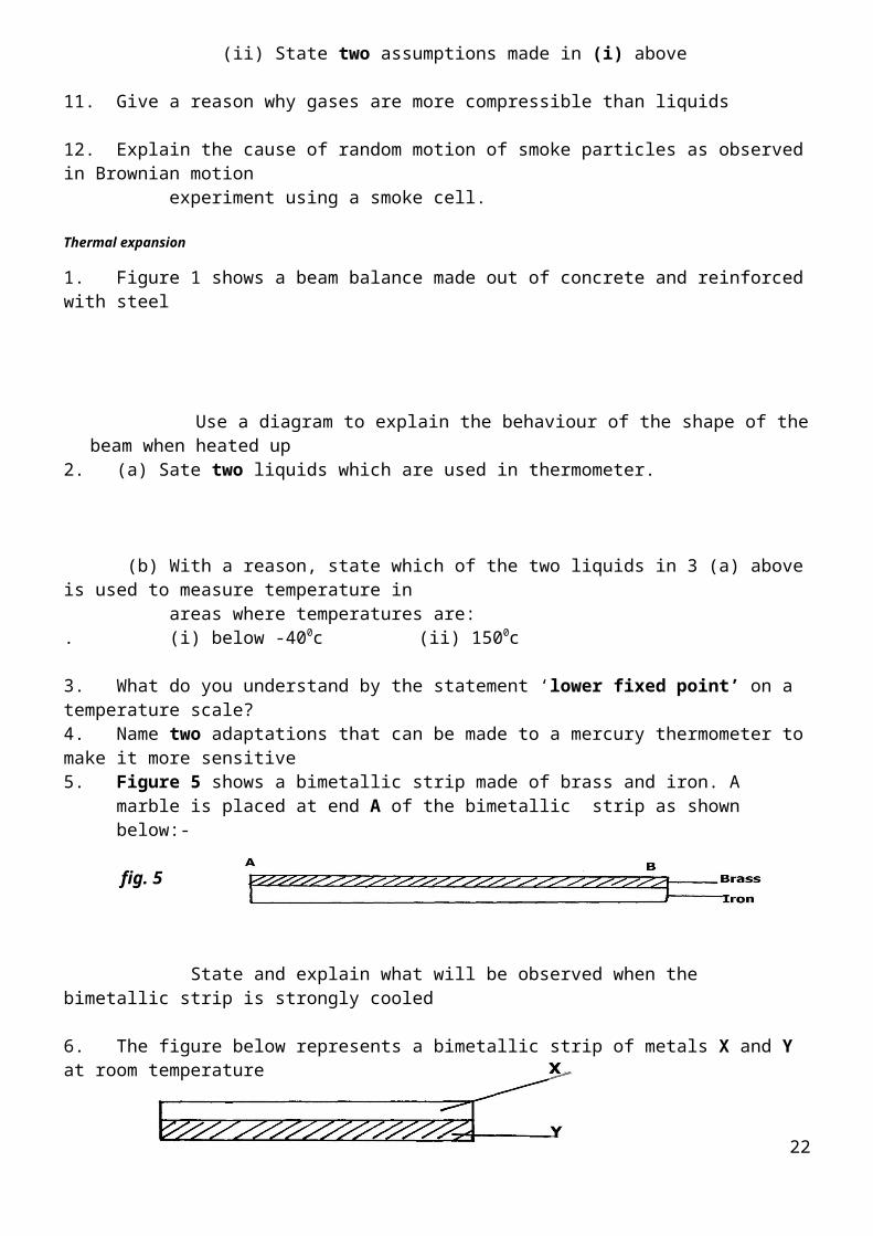
Figure 4
Q
Calculate the weight of the plate.Fluid flow
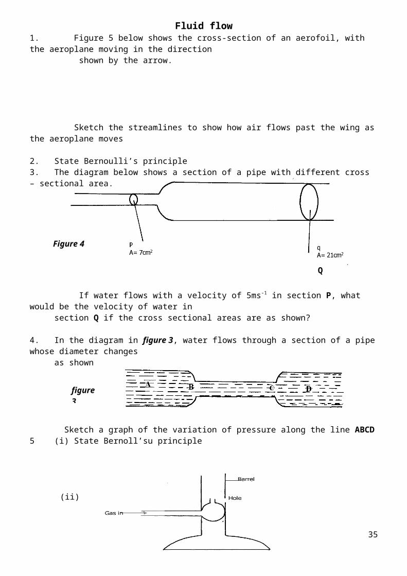
1. Figure 5 below shows the cross-section of an aerofoil, with the aeroplane moving in the direction shown by the arrow.
Sketch the streamlines to show how air flows past the wing as the aeroplane moves
2. State Bernoulli’s principle3. The diagram below shows a section of a pipe with different cross – sectional area.
If water flows with a velocity of 5ms-1 in section P, what would be the velocity of water in section Q if the cross sectional areas are as shown?
4. In the diagram in figure 3, water flows through a section of a pipe whose diameter changes as shown
Sketch a graph of the variation of pressure along the line ABCD5 (i) State Bernoll’su principle
(ii)
Explain how air is drawn into the barrel22
figure 3
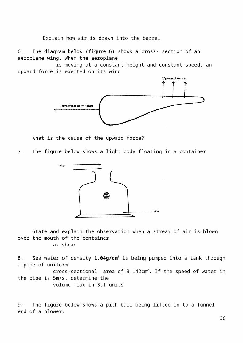
6. The diagram below (figure 6) shows a cross- section of an aeroplane wing. When the aeroplane is moving at a constant height and constant speed, an upward force is exerted on its wing
What is the cause of the upward force?7. The figure below shows a light body floating in a container
State and explain the observation when a stream of air is blown over the mouth of the container as shown
8. Sea water of density 1.04g/cm3 is being pumped into a tank through a pipe of uniform cross-sectional area of 3.142cm2. If the speed of water in the pipe is 5m/s, determine the volume flux in S.I units
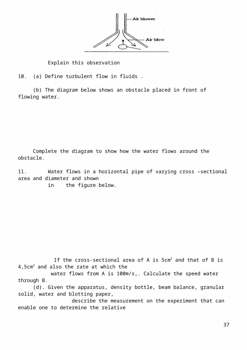
9. The figure below shows a pith ball being lifted in to a funnel end of a blower.
Explain this observation
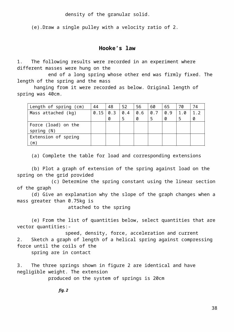
10. (a) Define turbulent flow in fluids . (b) The diagram below shows an obstacle placed in front of flowing water.
Complete the diagram to show how the water flows around the obstacle.
11. Water flows in a horizontal pipe of varying cross –sectional area and diameter and shown in the figure below.
23
If the cross-sectional area of A is 5cm2 and that of B is 4,5cm2 and also the rate at which the water flows from A is 100m/s,. Calculate the speed water through B. (d). Given the apparatus, density bottle, beam balance, granular solid, water and blotting paper, describe the measurement on the experiment that can enable one to determine the relative density of the granular solid. (e).Draw a single pulley with a velocity ratio of 2.
Hooke’s law
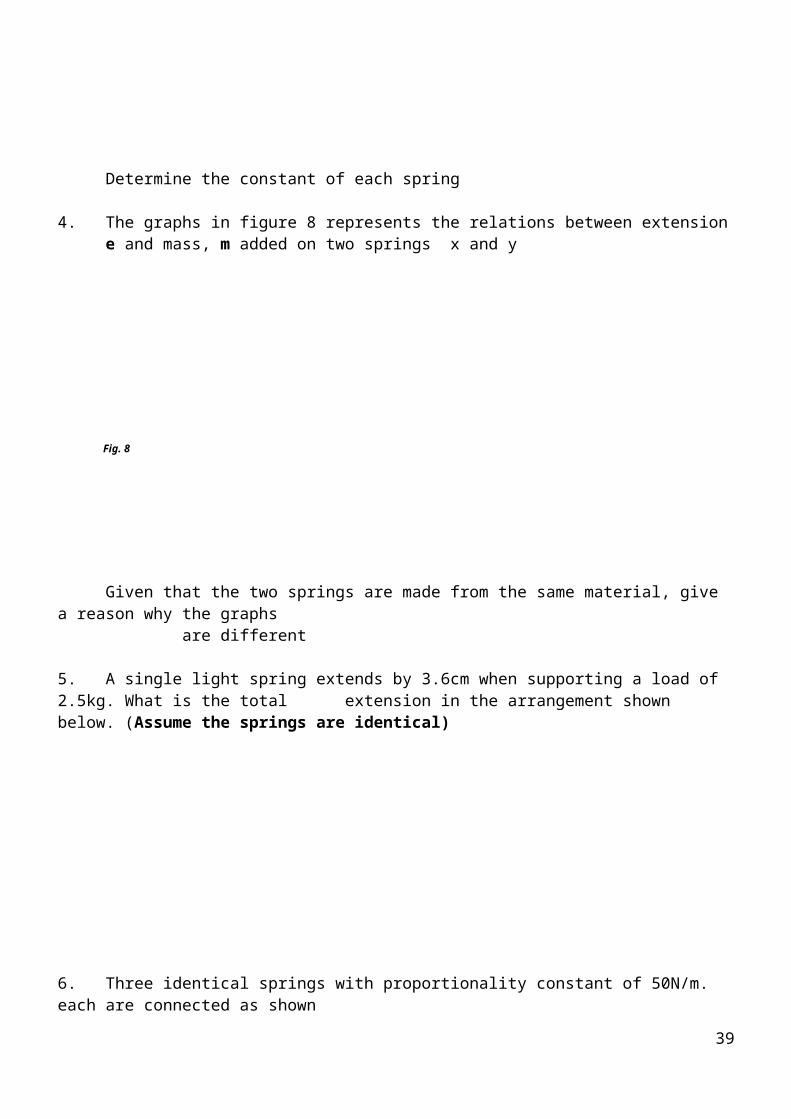
1. The following results were recorded in an experiment where different masses were hung on the end of a long spring whose other end was firmly fixed. The length of the spring and the mass hanging from it were recorded as below. Original length of spring was 40cm.
Length of spring (cm) 44 48 52 56 60 65 70 74Mass attached (kg) 0.15 0.30 0.45 0.60 0.75 0.90 1.05 1.20Force (load) on the spring (N)Extension of spring (m)
(a) Complete the table for load and corresponding extensions (b) Plot a graph of extension of the spring against load on the spring on the grid provided (c) Determine the spring constant using the linear section of the graph (d) Give an explanation why the slope of the graph changes when a mass greater than 0.75kg is attached to the spring (e) From the list of quantities below, select quantities that are vector quantities:- speed, density, force, acceleration and current2. Sketch a graph of length of a helical spring against compressing force until the coils of the spring are in contact
3. The three springs shown in figure 2 are identical and have negligible weight. The extension produced on the system of springs is 20cm
Determine the constant of each spring
4. The graphs in figure 8 represents the relations between extension e and mass, m added on two springs x and y
24
fig. 2
Given that the two springs are made from the same material, give a reason why the graphs are different
5. A single light spring extends by 3.6cm when supporting a load of 2.5kg. What is the total exten-sion in the arrangement shown below. (Assume the springs are identical)
6. Three identical springs with proportionality constant of 50N/m. each are connected as shown below and support a load of 60N
Calculate; (a) The extension in one spring (b) The extensive proportionality constant of the springs
7. When a load of 20N is hung from a spring, the spring has a length of 15 cm. The same spring has a length of 17 cm when supporting a load of 25N. Determine the spring length when supporting no load.The figure below shows a U-tube manometer. Use it to answer question 5 and 6. Density of water = 100 kgm-3.
8. The diagram below shows three identical springs which obey Hooke’s law.
25
Fig. 8
(i) Determine the length X.
Magnetism1. Use the domain theory to explain the process of magnetization
Reflection at curved surfaces11. a) Define the term magnification as applied to curved mirrors.
b) The table below shows the results obtained in an experiment with a concave mirror.
Image distance V(cm) 20 25 30 35 40 45Magnification (m) 1.0 1.5 2.0 2.5 3.0 3.5
i) Use your graph to determine the focal length of the mirror given that the equation relating m and v is such that: m+1= v fLinear motion
1. a) Distinguish between the terms ‘uniform velocity’ and ‘uniform acceleration’b) The figure below shows a section of a ticker tape. The dots were made at a frequency of 50 Hz. Determine the acceleration of the trolley pulling the tape
26

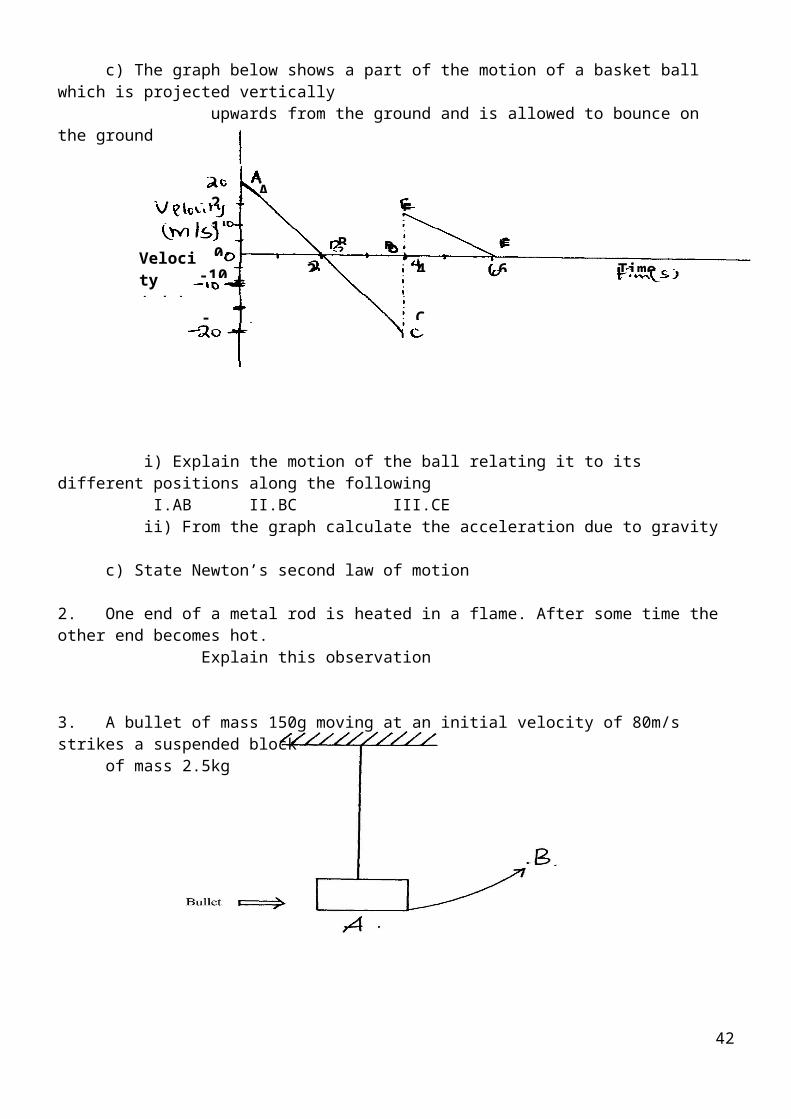
c) The graph below shows a part of the motion of a basket ball which is projected vertically upwards from the ground and is allowed to bounce on the ground
i) Explain the motion of the ball relating it to its different positions along the followingI.AB II.BC III.CE
ii) From the graph calculate the acceleration due to gravityc) State Newton’s second law of motion
2. One end of a metal rod is heated in a flame. After some time the other end becomes hot. Explain this observation
3. A bullet of mass 150g moving at an initial velocity of 80m/s strikes a suspended block of mass 2.5kg
3. (a)The block swings from point A to B. Determine the vertical displacement between A and B . (b) What observations are you likely to observe on the block after collision
4. The diagram below shows a velocity – time graph of a certain motion.
From the graph, determine the average speed of the body.
27
Figure 2
A20 E
Velocity (m/s)
DB F10
Time (s)6420
-10
-20 C
5. The diagram below shows a ball being whirled in a vertical plane.
(a) Sketch on the same diagram, the path followed by the ball if the string cuts when the ball is at position shown in the diagram.
6. The figure below shows a circuit diagram for controlling temperature of a room.
(i) Explain the purpose of the strip. (ii) Describe how the circuit controls the temperature when the switch S is closed.
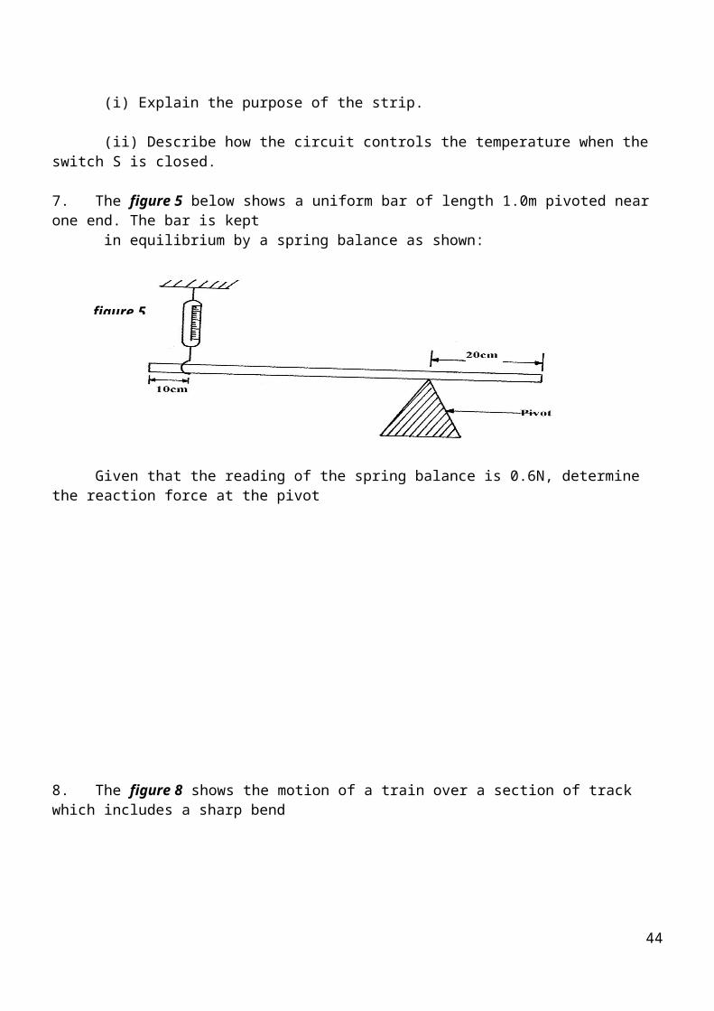
7. The figure 5 below shows a uniform bar of length 1.0m pivoted near one end. The bar is kept in equilibrium by a spring balance as shown:
Given that the reading of the spring balance is 0.6N, determine the reaction force at the pivot
28
Figure 7
Contact
figure 5

8. The figure 8 shows the motion of a train over a section of track which includes a sharp bend
(a) The section of the track with the sharp bend has a maximum speed restriction. The train decelerates approaching the bend so that at the start of the bend, it has just reached the
maximum speed allowed. The train is driven around the bend at the maximum speed
allowed and accelerates immediately on leaving the bend. Calculate the length of the bend
(b) The train has to slow down to go round the bend. Calculate the deceleration
(c) As the train is driven round the bend, there is an extra force acting, called the centripetal force.
(i) On the figure 9 below, draw an arrow to show the direction of this force
(ii) State the effect that this force has on the motion
(iii) State how this force is provided
29
figure 8
figure 9

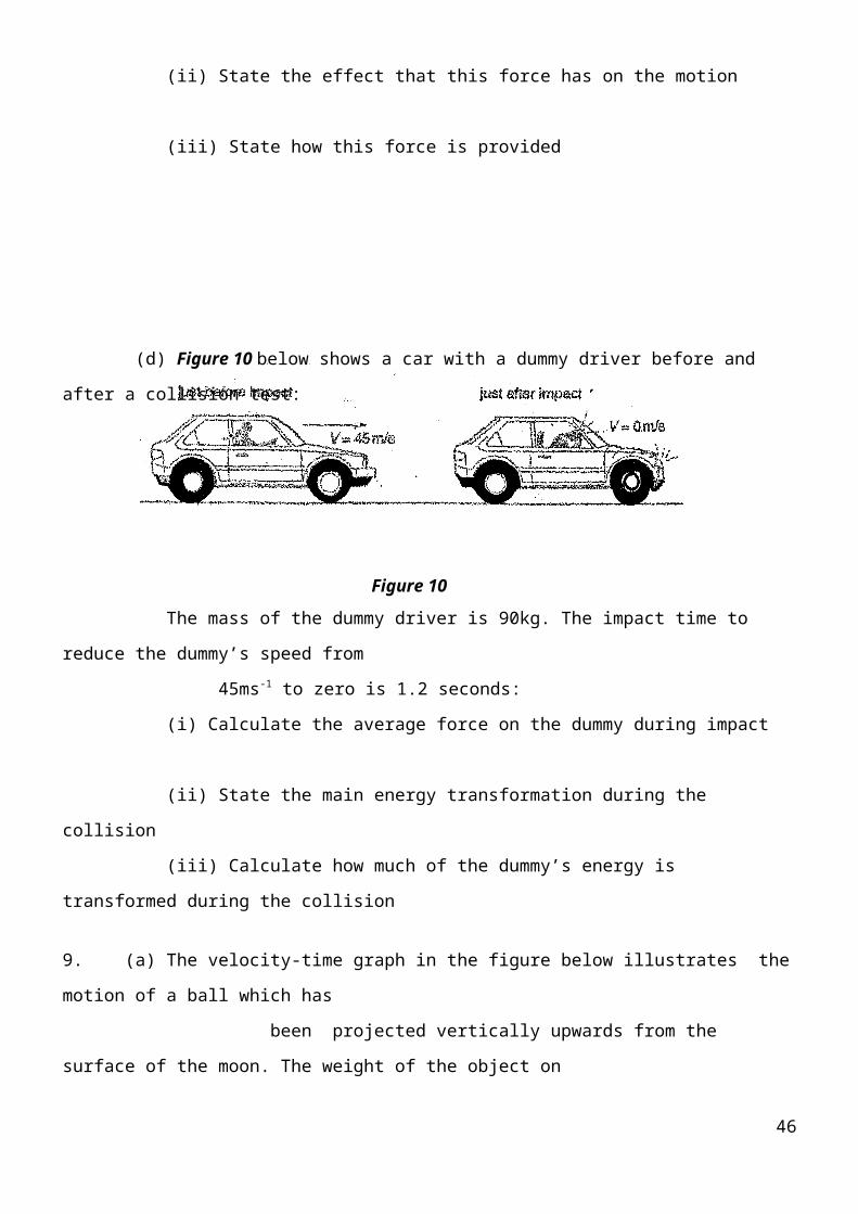
(d) Figure 10 below shows a car with a dummy driver before and after a collision test:
The mass of the dummy driver is 90kg. The impact time to reduce the dummy’s speed from
45ms-1 to zero is 1.2 seconds:
(i) Calculate the average force on the dummy during impact
(ii) State the main energy transformation during the collision
(iii) Calculate how much of the dummy’s energy is transformed during the collision
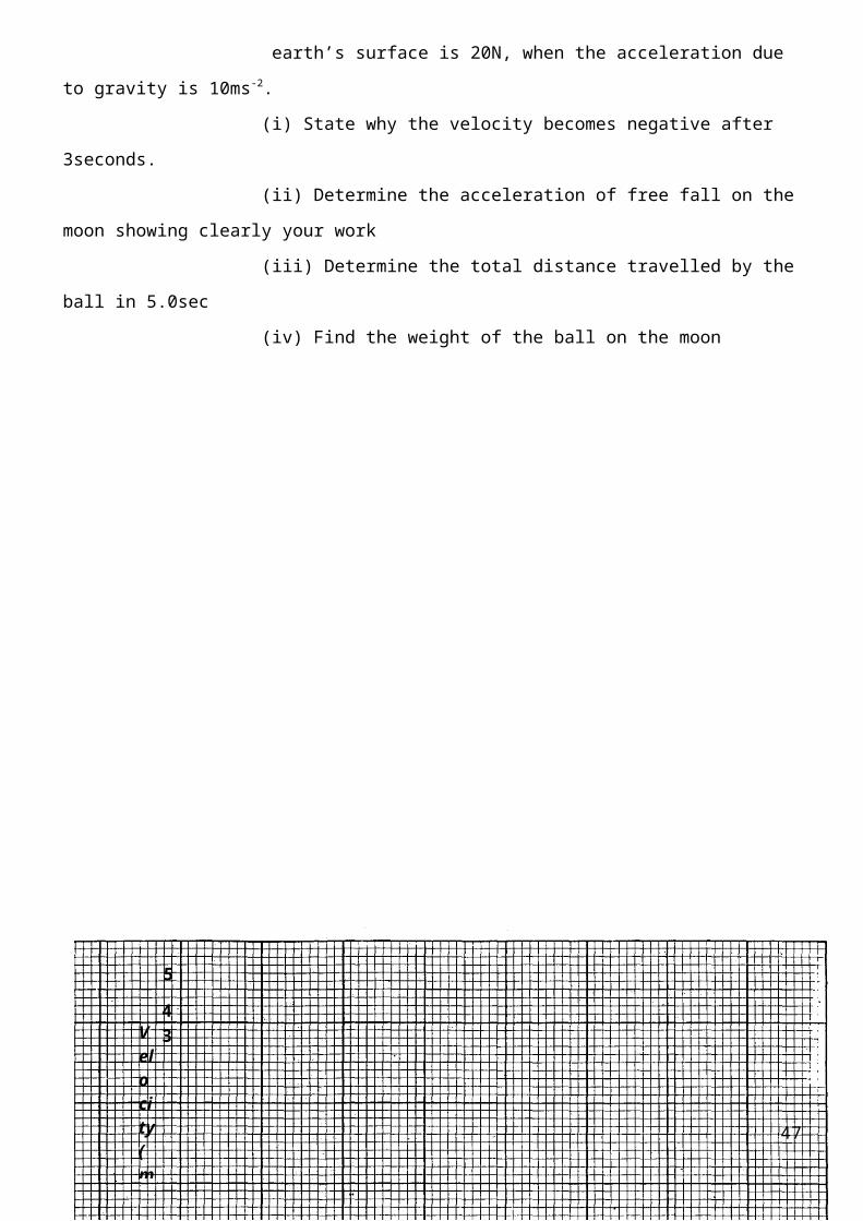
9. (a) The velocity-time graph in the figure below illustrates the motion of a ball which has
been projected vertically upwards from the surface of the moon. The weight of the object on
earth’s surface is 20N, when the acceleration due to gravity is 10ms-2.
(i) State why the velocity becomes negative after 3seconds.
(ii) Determine the acceleration of free fall on the moon showing clearly your work
(iii) Determine the total distance travelled by the ball in 5.0sec
(iv) Find the weight of the ball on the moon
30
Figure 10

(v) If the ball was projected vertically upwards on the earth with the same velocity. What difference would you expect to observe in the velocity-time graph above. Illustrate with a sketch on the same axis
(b) The figure below represents part of a tape pulled through a ticker-timer of frequency 50Hz moving down an inclined plane.
If the trolley was allowed to move down the inclined plane for 4 seconds, calculate the distance it covers
10. (a) State Boyle’s law (b) The volume of a bubble at the base of a container of water is 3cm3. The depth of water is 30cm. The bubble rises up the column until the surface ; (i) Explain what happens to the bubble as it rises up the water column (ii) Determine the volume of the bubble at a point 5cm below the water surface (c) A faulty thermometer records 11oC instead of 0oC and 98oC instead of 100oC. Determine the reading on the thermometer when dipped in liquid at a temperature of 56oC
31
5
4Ve-loc-ity (ms-
3
1
0654321
-1 Time (s) ---2--3
-4

11. Figure 9 is a velocity- time graph describing the motion of a particle
What does the shaded area represent?
12. a) State Newton’s first law of motion
b) A parcel is to be dropped from an aeroplane traveling horizontally at 120ms-1, at an altitude
of 720m, to fall into a certain village.
Determine:
i) The time taken for the parcel to reach the ground
ii) How far ahead of the plane, the village should be when the parcel is released
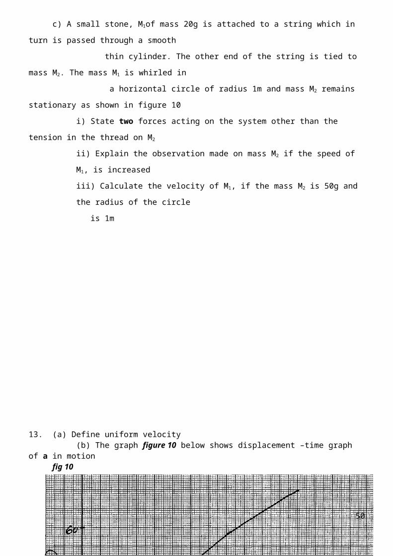
c) A small stone, M1of mass 20g is attached to a string which in turn is passed through a smooth
thin cylinder. The other end of the string is tied to mass M2. The mass M1 is whirled in
a horizontal circle of radius 1m and mass M2 remains stationary as shown in figure 10
i) State two forces acting on the system other than the tension in the thread on M2
ii) Explain the observation made on mass M2 if the speed of M1, is increased
iii) Calculate the velocity of M1, if the mass M2 is 50g and the radius of the circle
is 1m
32
Fig. 9

13. (a) Define uniform velocity (b) The graph figure 10 below shows displacement –time graph of a in motion
fig 10
(i) Determine the instanteous velocities at t = 1second and at t = 4 seconds
(ii) Use the results in (b)(i) above to determine the acceleration of the body
14. A ball of mass 100g is kicked horizontally from the top of a cliff. If the ball takes 4 seconds
to hit the ground, determine the height of the cliff
15. A ball is kicked vertically upward from the ground with a velocity of 60m/s and reaches a maximum height (h), it then falls freely back to the ground and bounces upwards to a height of 5M (a) Sketch a velocity-time graph to represent the motion of the ball from the time it is kicked vertically upwards until it bounces to a height of 5M (b) Determine: (i) the time taken by the ball to reach the maximum height(h) (ii) The maximum height (h) reached by the ball
33

(iii) The velocity with which it bounces after striking the ground for the first time (c) State any assumption made in your calculations in (b) above
16. In an experiment on momentum, trolley P of mass 800g was attached to a ticker timer of fre-quency 50Hz. Trolley P, initially moving with a velocity of 0.5m/s, was made to collide
with a stationary trolley Q of mass 400g. A copy of the tape as it appeared after the collision is presented in the figure below:-
(a) Determine the velocity of the trolley P after collision (b) Calculate the impulsive force experienced by trolley P (c) State the type of collision
17. I. (a) State the three equations of linear motion. (b) A car is traveling uniformly at 100km/hr when the driver observes a road block ahead.
He takes 0.5 s before applying the brakes which brings the car to rest with a uniform deceleration of 4m/s2. Determine the distance traveled by the car from the time the driver observed the road block until the car comes to rest.
(c) A car moves at a constant speed of 20ms-1 for 50s and then accelerates uniformly to a speed of 25ms-1 over a period of 10s. This speed is maintained for 50 s before the car is brought to rest with uniform deceleration in 15s.(d) Draw a graph of velocity (Y – axis) against time (graph paper to be availed)(II) Calculate: (i) The average speed for the whole journey. (ii) The acceleration when the velocity changes from 20 ms-1 to 25ms-1 . m, show that v2=2as +u2
18. Sketch a velocity-time graph for a body moving with zero acceleration
19. The figure below shows a velocity –time graph of a ball bouncing vertically upward from the ground. The velocity upward is taken positive.
Determine the maximum height when the ball rises.
34
20. (a) On the axes provide below, sketch a graph of velocity V versus time (t) for uniformly accelerated motion given that when t = 0, V is greater than zero.
(b) A car is brought to Rest from a speed of 20 ms-1 in time of 2 seconds. Calculate the deceleration. 21. (a). State the law of linear momentum (b). A marble of mass 50g moving on a horizontal surface at a velocity of V collides with another glass marble of mass 75g resting on same horizontal surface. After collision, the marble bounces back a long the path at a speed of 3.5m/s while the other marble moving with a speed of 3.0m/s .Forward . Determine the speed V. (c). The paper below was attached to a trolley and pulled through a ticker tape times of frequency 50Hz. Determine the acceleration of the trolley.
(d). Study the figure below
Calculate the pressure in the steam in the cylinder which would just raise the piston if area of of the piston in contact with steam is 2cm2 and Atmospheric pressure is1.0 x 105 Nm-2. (e) State a reason why the earth is colder at night than daytime during a sunny
21. A block of mass 20kg slides downward a plane inclined of 6o0 with the horizontal. The coeffi-cient of friction between the plane and the block is 0.4.
35
Effort1000N
4000N
Calculate the acceleration of the block. 22. A body accelerates uniformly from initial velocity of U m/s to a final velocity of V m/s in time t seconds. If acceleration during the motion is a m/s2 and the distance covered is S
Machines & inclined planes1. An inclined plane of length 5m is used to raise a body of mass 60kg to the back of a lorry. If the plane is inclined at an angle 25° from the horizontal, calculate the efficiency of the system given that a constant force of 650 N is used to push the body up the plane
2. Vicky performed an experiment using a pulley system as shown in the figure.
(a) What is the V.R. of the system?(b) Determine the M.A. of the system. *(c) Calculate the efficiency of the system. (d) Explain why efficiency of a practical machine is always less than 100% (e) If the load moves a distance of 5 cm. Find the work done on the load.
3. The figure below shows a pulley system being used to raise a load. Use the information given in the figure to answer questions (a) and (b)
36
Figure 13
LOAD
Load
fig. 3
(ii) If a load of 100N is raised by applying an effort of 48N, determine the efficiency of the system.
4. (a) (i) Define the term velocity ratio (V.R) (ii) Name one machine that has a velocity ratio of less than one (V.R < 1) (b) The figure below shows a set-up used to find the mechanical advantage of a pulley system
On the axes provided sketch a graph of mechanical advantage (M.A) against load (L)
(c) A hydraulic machine is used to raise a load of 100kg at a constant velocity through a height of 2.5m. The radius of the effort piston is 1.4cm while that of the load piston is 7.0cm. Given that the machine is 80% efficient, calculate:- (i) The effort needed (ii) The energy wasted in using the machine
5. (i) complete the diagram below to show how the pulley can be used to raise a load L by applying an effort E
37
(ii) The pulley system above has a mechanical advantage of 3. Calculate the total work done when a load of 60N is raised through a height of 9MNewton’s law1. (a) State Newton’s first law of motion (b) Distinguish between elastic collision and inelastic collision (c) A minibus of mass 2000kg traveling at a constant velocity of 36km/h collides with a stationary car of mass 1000kg. The impact takes 2 seconds before the two move together at a constant velocity for 20 seconds. Calculate: (i) The common velocity (ii) The distance moved after impact (iii) The impulse force (iv) The change in kinetic energy2. State Newton’s second law of motion3. State the law of inertia4. A footballer kicks a ball of 600g initially at rest using a force of 900N. If the foot was in
contact with the ball for 0.1sec. What was the take off speed of the ball? 5. State Newton’s third law of motion
6. (a) State Newton’s second law of motion (b) The figure below shows two mini buses A and B at a speed of 40m/s and 20m/s respectively moving in opposite directions. They collided head on
Determine the common speed of the vehicles if they stuck to each other
Circular motion1. Give a reason why bodies in circular motion undergo acceleration even when their speed is constant2. a) Define the term angular velocity
b) The figure shows a body of mass m attached to the centre of a rotating table with a string whose tension can be measure. (the device for measuring tension is not shown in the figure)
The tension T, on the string was measured for various values of angular velocity, w. The distance r from the centre was maintained at 30cm. The results are as shown below :
Angular velocity w (rad -1) 2.0 3. 4.0 5.0 6.0Tension T (N) 0.04 0.34 0.76 1.30 1.96
38
i) Plot the graph of T (y – axis) againstw2
ii) From the graph, determine the mass, m, of the body given that T = mw2 r – C Where C is a constant
iii) Determine the constant C and suggest what it represents in the set up3. (a) A body moving in a uniform circular motion accelerates even though the speed is constant.
Explain this observation. A fun fair ride of diameter 12m makes 0.5 revolutions per second. (i) Determine the periodic time, T, of the revolutions. (ii) Determine its angular velocity, w. (iii) Determine the linear velocity of the child riding in it.
(iv) If the mass of the child is 30 kg, find the centripetal force that keeps the child in the motion.
4 . Figure 6 shows a body of mass m attached to the centre of a rotating table with string whose tension can be measured (the device for measuring the tension is not shown in the figure)
The tension T, on the string was measured for various values of angular velocity w. The distance r of the body from the centre was maintained at 60cm. Table 2 shows the results obtained:-
Angular velocity (w) (rads-1) 2.0 3.0 4.0 5.0 6.0Tension (T) (N) 0.04 0.34 0.76 1.30 1.96
(i) Plot the graph of T against w2
(ii) From the graph determine the mass m of the body given that T = mw2r – C, where C is constant
(iii) Determine the constant C and suggest what it represents in the set-up
5. (a) (i) In uniform circular motion, a particle undergoes an acceleration while its speed remains constant. Explain how the acceleration if caused (ii) A car of mass 1.5 x 10³kg negotiates a level round about of radius 20m at a speed of 10m/s. Calculate the centripetal force acting on the car (b) The diagram figure 15 below shows a conical pendulum:-
fig. 15
(i) State and explain the effect on r of increasing the speed of the pendulum, given that the string is inextensible (c) Explain why a cyclist going round a bend at high speed tilts inwards
39
fig.6
String rw

6. (a) Define angular velocity (b) The figure below shows an object of mass 0.2kg whirled in a verticle cycle of radius 0.5m at uniform speed of 5m/s
Determine (i) The tension in the string at position A (ii) The tension in the string at position B (iii) The tension in the string at position C (c) From the values obtained in (i) (ii) and (iii) above, determine the point the string will most likely snap. Explain (d) A small pendulum bob having a mass of 150g is suspended by an inelastic string of length 0.5m. The mass is made to rotate in a horizontal circle of radius 0.4m and whose centre is vertically below the point of suspension (i) Determine the tension in the string (ii) State one application of the pendulum
7. (a) Explain why a body moving in a circular path with constant speed is said to be accelerating (b) (i) A wooden block of mass 200g is placed at various distances from the center of a turntable, which is rotating at constant angular velocity. It is found that at a distance of 8.0cm from the center, the block just starts to slide off the table. If the force of friction between the block and the table is 0.4N, Calculate: (I) The angular velocity of the table (II) The force required to hold the block at a distance of 12cm from the center of the table (c) A block of mass 400g is now placed at distance of 8.0cm from the centre of the turntable in (i) above and the turntable rotated at the same angular velocity. State with a reason whether or not the ball will slide off
8. A small object moving in a horizontal circle of radius 0.2m makes 8 revolutions per second. Determine its centripetal acceleration
9. (a) The figure below shows a body of mass m attached to the centre of a rotating table with a string whose tension can be measured. The device for measuring the tension is not shown in the diagram:
The tension T on the string was measured for various values of angular velocity,w . The distance r of the body from the centre was maintained at 30cm. The graph below shows the results obtained when Tension (y-axis) is plotted against (angular velocity w)2
(i) Name the force represented by the Tension (T)40

(ii) From the graph, determine the mass m, of the body given that T=Mw2r - c where c is a constant
(iii) Determine the constant c and suggest what it represents in the set-up
10. A mass of 2kg is attached to a string of length 50 cm. It is whirled in a circle in a vertical plane at 10 revolution per second about a horizontal axis. Calculate the tension in the string when the mass is at the :-(a) Highest point of the circle. (b) Lowest part of the circle.
41
(Angular velocity w)2
-0.2
r
Glass tube
Masses
Thin cotton thread
11. A bucket full of water is whirled in a vertical circle of radius 1.6m, determine the minimum speed required to keep the water intact.
1. (a). The set up in the figure below was used to investigate the variation of the centripetal force F with the radius of a circle in which a body rotates. Various Masses were hooked on thread passing through a glass tube to balance circular motion as shown.
The table below shows the results obtained from the above experiment
Radius v(cm) 15 25 34 40 50 61Mass m(kg) 0.02 0.03 0.04 0.05 0.06 0.07
(i). Plot a graph of tension T in the thread against radius of circular motion. (ii). Use the results above to determine the angular velocity of the body if its mass is 15g. (b). (i). Determine the time a 3kw heater takes to melt 10kg. f ice at 0oC to water at 50oC.
Take specific latent heat of fusion for ice as 3.34 x 10⁵ j/kg while specific heat capacity of Water as 4200j/KgoC . (ii). State one assumption made in the kinetic theory of gases. Sound II1. A student carrying out an experiment discovered that it took 2 seconds for sound wave traveling through a telephone line to cover a distance d metres and 20 seconds for the same sound traveling through air to cover a similar distance. Determine the ratio of the speed of sound in air to that in the wire.
Thin lenses
1. Use a ray diagram to show how short sightedness in a human eye can be corrected. Quality of heat
1. (a) Define the term specific heat capacity. (b) A block of metal of mass 300g at 1000c is dropped into a logged calorimeter of heat capacity 40Jk-1, containing 200g of water at 200c. The temperature of the resulting mixture is 340c. (Specific heat capacity of water = 4200Jkg-1k-1) Determine: (i) Heat gained by calorimeter. (ii) Heat gained by water. (iii) Heat lost by the metal block. (iv) Specific heat capacity of the metal block.
42
Body Body

2. (a) State two differences between boiling and evaporation. (b) 200g of a solid was uniformly heated by a 0.2 kw heater for sometime. The graph in the
figure below shows how the temperature of the solid changed with time.
(i) Explain what is happening between OA and AB.(ii) Calculate the specific heat capacity of the solid. (iii) Calculate the specific latent heat of fusion k of the solid.
3. (a) Define the term heat capacity (b) A block of metal of mass 150g at 100oC is dropped into a logged calorimeter of heat capacity 40Jk-1 containing 100g of water at 25oC. The temperature of the resulting mixture is 34oC. (Specific heat capacity of water = 4200J/KgK) Determine;- (i) Heat gained by calorimeter
(ii) Heat gained by water (iii) Heat lost by the metal block (iv) Specific heat capacity of the metal block
4. (a) Distinguish between evaporation and boiling (b) A jet delivering 0.44g of dry steam per second, at 100oC is directed on to crushed ice at 0.0oC contained in an unlagged copper can which has a hole in the base. 4.44g of water at 0.0oC flow out of the hole per second (i) How many joules of heat are given out per second by condensing steam and cooling to 0.0oC of water formed?(Latent heat of vaporization of steam = 2.26 x 10⁶JKg-1,
c for water = 4200JKg-1K-1) (ii) How much heat is taken in per second by the ice which melts? (iii) Suggest why these amounts above are different (c) Figure 7 below shows a cross-section of a vacuum flask
(i) Name the parts labelled A and B on the diagram43
(ii) Explain how the heat losses are minimized when hot liquid is poured into the flask
5. (a) Figure 2 shows two identical thermometers. Thermometer A has a blackened bulb while thermometer B has a silvery bulb. A candle is placed equidistant between the two thermometers
State with a reason the observations made after some time5. (b) Figure 3 shows a test tube partially filled with water. An ice wrapped in wire gauze is
placed at the bottom of the test-tube. It is then held in the flame of a bunsen burner as shown below
fig. 3
State and explain what will be observed after some time6. Give any two differences between evaporation and boiling7. Explain why steel feels colder than wood at the same temperature
8. An electric heater 1KW 240V is used to raise the temperature of a 5kg copper block from 15oC to 33oC. If the specific heat capacity of copper is 400JKg-1K-1 and assuming no heat is lost to the surrounding, Calculate the time taken
9. (a) Define specific latent heat of fusion (b) 0.5kg of naphthalene contained in an aluminium can of mass 0.4kg is melted in a water
bath and raised to a temperature of 100oC . Calculate the total heat given out when the can and its contents are allowed to cool to room temperature, 20oC . Neglect losses by evaporation during heating process and give your answer to the nearest kilojoule.
(For naphthalene melting point = 80oC , Specific heat capacity for both liquid and solid =2100J/KgK; specific latent heat of fusion = 170000J/Kg.
For aluminium: specific heat capacity = 900J/Kgk (c) Briefly explain two ways other than direct heating by which quantity of liquid may be made to evaporate more quickly (d) The diagram below shows a charcoal refrigerator
44
Fig. 2

(i) Explain why charcoal is used and why it is sprinkled with water (ii) What is the role of the metallic tank and the wire mesh
10. An electric kettle with a shinny outer surface would be more efficient than one with a dull outer surface. Give a reason for this
11. A heating element rated 2.5 KM is used to raise the temperature of 3.0 kg of water through 50oC. Calculate the time required to Effect this. (Specific heat capacity of water is 4200J/kgK).
Work, energy and power1. (a) State the law of conservation of energy (b) The graph below shows the potential energy against displacements for a body of mass 80g
The body oscillates about point R. Calculate the velocity of the body at: (i) P and T (ii) Q and S (iii) at R (c) A wheel and axle are used to raise a load of 280N by a force 40N applied to the rim of the wheel. If the radii of the rim and axle are 70cm and 5cm respectively, calculate:
(i) The mechanical advantage (ii) The velocity ratio (iii) The efficiency
2. (a) A bicycle has wheels 66 cm in diameter. Its crank wheel has 44 teeth and the rear sprocket 16 teeth. The crank radius is 16.5 cm. (i) Determine the radius of the rear sprocket. (ii) The bicycle moves when the rear sprocket is made to move. Hence determine the velocity ratio. (b) A man uses a block and tackle mechanism of velocity ratio 6 to lift a car engine smoothly through a height of 1 m in 5s. The man applies a force of 300N while the mass of the engine is 120 kg. Determine: (i) The mechanical advantage of the pulley system. (ii) its efficiency.
45
3. (a) Define work and state its S.I units (b) A crane lifts a load 500kg through a vertical distance of 4m in 8 seconds. Determine: (i) Work done by the crane (ii) Power developed by the crane (iii) Efficiency of the crane given that it is operated by an electric motor rated 2.8Kw (iv) State two effects which contribute to the efficiency being less than 100%
4. A load of 100N is raised using the system in the figure below by an effort.
Given that the efficiency of the machine is 90%, calculate the minimum effort.
Floating and sinking1. (a). State Archimedes’s Principle . b). A during bell of weight 60,000N and volume 2m3 is to be raised from the bottom of the sea. If the density of sea water is 1024kg/m3, calculate: (i) the mass of sea-water displaced by the bell. (ii) The force a crane must first exert to just lift the bell from the sea-bed. (c). The figure below shows a bock of wood of dimension 16cm x 8cm 2cm floating with ¾ of its size submerged in a liquid.
During the experiment with the following set-up above, the following results were obtained. -Initial reading of the Toppan balance with empty beaker = 22g.
-Final reading of the top pan balance = 176g. Use the above results to determine:
(i). the density of the block (ii). The density of the liquid. 2. (a) A piece of sealing wax weighs 3N in air and 0.22N when immersed in water. Calculate:
(i) Its relative density. (ii) Its apparent weight ,in a liquid of density 800 kgm-3.(b) The figure below shows a uniform beam one metre long and weighing 2N kept in
horizontal position by a body of weight 10N immersed in a liquid. Determine the upthrust on the load.
46
3. A bubble of air has a diameter of 2.0 mm when it is 0.5m below the water surface of a boiler. Calculate the diameter of the bubble as it reaches the surface, assuming that the temperature remains constant. (Take g = 10Nkg-1 density of water = 103kgm-3 and atmospheric pressure = 105Mn-2
4. (a) State the Archimedes principle (b) The figure below shows a block of mass 25g and density 200kg/m3 submerged beam by means of a thread. A mass of 2g if suspended form the beam as shown in the figure below
(i) Determine the up thrust force acting on the block (ii) Calculate the density of the liquid (c) A rectangular block of dimensions 4m x 3m x 2m is tethered to the sea bed by a wire. If the density of the material making the block is 0.67g/cm3 and density of water is 1.1g/cm3,
calculate: (i) Up thrust force on the block (ii) Tension on the wire
5. Explain why a needle can be carefully made to float in pure water but sinks if a detergent is added.
6. (i) State the law of floatation. (ii) The fig. below shows a floating object of volume 40,000 cm3 and mass 10g. It is held as
shown in water of density 1.25g/cm3 by a light cable at the bottom so that ¾ of the volume of the object is below the water surface. (Assume that up thrust due to air is negligible)
(iii) (I) Calculate the volume of the object under water.(II) State the volume of water displaced by the object.(III) Calculate the weight of water displaced.
(iv) Determine the tension in the cable (v) Calculate the density of the object.
7. (a) A trolley is being pulled horizontally from a ticker-tape timer. The figure below shows part of the ticker-tape.
47
Figure 11
Figure 12

(i) Find the average velocity, u, at the section marked A. (ii) Find the average velocity, V at the section marked B.(iii) Find the acceleration of the trolley between A and B.(b) If the mass of the trolley is 500g, determine the resultant force which acted on the trolley that caused the acceleration.
8. (a) State Archimedes’ principle (b) (i) Draw a clearly labelled diagram of common hydrometer which is suitable for measuring the densities of liquids varying between 1.0 and 1.2 g/cm3. Show clearly the marks indicating 1.0, 1.1 and 1.2 g/cm3. (ii) State the principle upon which the instrument’s use depends (c) A concrete block of volume V is totally immersed in sea water of density J.Write an
expression for the upthrust on the block
9. (a) Define the term relative density(b) The diagram below shows a wooden log 12m long, density 800kg/m3 and cross-sectional area 0.06m2 floating upright in sea water of density 1.03g/cm3, such that a third of it is covered by water.
(i) Determine the weight of the block (ii) The up-thrust on the block (iii) The minimum weight that can be placed on the block to just make it fully submerged (c) The following set-up was then used by a student to determine the relative density of a cork
During the experiment, the following measurements were taken:- - Weight of sinker in water = w1
- Weight of sinker in water and cork in air = w2
- Weight of sinker and cork in water = w3
(i) Write an expression for the up thrust on cork (ii) Write an expression for the relative density of the cork
10. (a) State the law of floatation (b) The diagram figure 11 below shows a block of wood floating on water in a beaker. The set-up is at room temperature:-
48
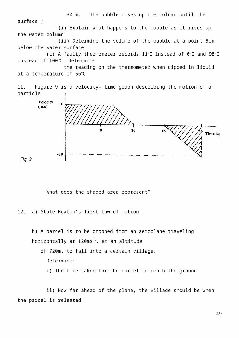
fig. 11
The water in the beaker is warmed with the block still floating on it. State and explain the changes that are likely to occur in depth x
(c) The diagram figure 12 below shows a balloon which is filled with hot air to a volume of 200m3 . The weight of the balloon and its contents is 2200N.fig. 12
(i) Determine the upthrust on the balloon (density of air 0.0012g/cm3) (ii) The balloon is to be balanced by hanging small rats each of mass 200g on the lower end of the rope. Determine the least number of rats that will just make the lower end of the rope touch the ground.11. (a) State Archimedes’s principle (b) A rectangular brick of mass 10kg is suspended from the lower end of a spring balance and gradually lowered into water until its upper end is some distance below the surface (i) State and explain the changes observed in the spring balance during the process (ii) If the spring reads 80N when the brick is totally immersed, determine the volume of the brick. (Take density of water = 1000kgm-3)
(c) The figure below shows a hydrometer
Explain: (i) Why the stem is made narrow (ii) Why the bulb is made wide (iii) Why the lead-shots are placed at the bottom 12. (a) State the law of floatation (b) The diagram below shows a wooden block of dimensions 50cm by 40cm by 20 cm held in position by a string attached to the bottom of a swimming pool. The density of the block is 600kgm-3
49
(i) Calculate the pressure in the bottom surface of the block (ii) State the three forces acting on the block and write an equation linking them when the block is stationary (iii) Calculate the tension on the string
13. A block of glass of mass 250g floats in mercury. What volume of glass lies under the surface of Mercury? Density of mercury is 13.6 x 10³ Kg/m3
14. a) State the law of floatationb) A balloon of negligible weight and capacity 80m3 is filled with helium of density 0.18Kgm-3.
Calculate the lifting force of the balloon given that the density of air = 1.2Kgm-3
c) A piece of glass has a mass of 52g in air, 32g when completely immersed in water and 18g when completely immersed in an acid. (Take: density of water = 1g/cm3) Calculate:
i) Density of glass ii) Density of the acid
Electronics1. The figure below shows the set up for a simple cell.
a) Name the Electrode A and the solution B b) State two reasons why the bulb goes off after a short time
X-ray12. a) State the energy changes that take place in an X - ray tube b) Electrons in an X-ray tube are accelerated by a potential difference of 40 kV. If 20 % of the
electrons are converted into X- rays, determine the maximum wavelength of the emitted
electrons.
c) i) Draw a simple circuit consisting of a photocell to show the direction of flow of current
ii) The diagram below shows a wave form displayed on a CR0 screen.
50
If the Y — gain reads 0.5V cm-1 while the time base is set at 0.1 ms cm-1, determine the amplitude and frequency of the wave.
Radioactivity1. A radioactive substance X decays by emission of two alpha particles and one beta particle. Write a balanced equation of this emission.
GAS LAWS1. (a) State Boyle’s law
(b) A column of air 5cm is trapped by mercury thread of 10cm as shown in the figure below. If the tube is laid horizontally as shown in (b), calculate the new length of trapped air (atmospheric pressure =75.0cmHg and density of mercury = 13600kgm-3)
`
(c) Explain why: (i) It is difficult to remove the lid from a preserving jar which was closed when the (ii) A force pump must be used instead of a lift pump to raise water from a deep well over 10m
2. The figure below shows a simple set up for pressure law apparatus:-
a) Describe how the apparatus may be used to verify pressure law b) The graph in the figure below shows the relationship between the pressure and temperature for a fixed mass of an ideal gas at constant volume
51

i) Given that the relationship between pressure, P and temperature, T in Kelvin is of the formP = kT + C
Where k and C are constants, determine from the graph, values of k and C ii) Why would it be possible for pressure of the gas to be reduced to zero in practice?c) A gas is put into a container of fixed volume at a pressure of 2.1 x 10⁵. Nm-2 and
temperature 27°C. The gas is then heated to a temperature of 327°C. Determine the new pressure
3. (a) State Boyle’s law (b) The volume of a bubble at the base of a container of water is 3cm3. The depth of water
is 30cm. The bubble rises up the column until the surface ; (i) Explain what happens to the bubble as it rises up the water column (ii) Determine the volume of the bubble at a point 5cm below the water surface (c) A faulty thermometer records 11oC instead of 0oC and 98oC instead of 100oC. Determine the reading on the thermometer when dipped in liquid at a temperature of 56oC
4. (a) State Boyles law Some students carried out an experiment to verify Boyle’s law and recorded their results as shown in the table below:-
Pressure KN/ M2 400 320 160 180Volume (m3) 2.0 2.5 5.0 10.01/V (mm-3)
(i) Complete the table (ii) Plot a graph of pressure against 1/volume
(c) Determine the gradient for the graph and state its units (d) A sample of gas has a pressure of 1.0 x 10⁵Pa when its temperature is 10oC. What will be its pressure if its temperature is raised to 100oC and its volume doubled
5. (a) State: (i) Boyle’s Law (ii) Charles’ Law.(b) A form three student carried out an experiment on one of the gas law. She obtained the following results.
Temperature (0c) 10 35 60 80 90 110Volume V(cm3) 5 5.8 6.4 7.0 7.2 7.8
52

(i) Plot a graph of volume V against temperature. (ii) From the graph, determine the volume of the gas at 0oc. (iii) Determine the slope of the graph. (iv) The equation of the line obtained is of the form V = kT + c. What is the value of k and c?
6. (a) State Charles’ law (b) A mass of gas occupies a volume of 150cm3 at a temperature of -73°C and a pressure of 1 atmosphere. Determine the 1.5 atmospheres and the temperature 227 °C
7. In an experiment to verity Boyle’s law, two quantities were advised to be kept constant
(a). State the quantities.
(b). the results of experiment to verify Boyle’s law were recorded in the table below.
Pressure(atmospheres) 1.0 1.2 1.4 1.6 1.8
Volume (litres) 0.62 0.521 0.450 0.391 0.351
Plot a suitable graph to verify the law.
(c). Determine the volume of the gas when the pressure is two atmospheres.
SECTION 1- ANSWERSMeasurement I
1. (a) Density is the mass per unit volume of a substance, while relative density is the number of times a substance is denser than water- 2mks of each is defined properly (b) By law of floatation,
(c) Mass of the ship = mass of water displaced Mass of water displaced = 1300000kg Volume of water displaced = mass Density = 1,300,000kg 1025kg/m3
= 1268.3m3
(ii) Weight of ship – weight of cargo = upthrust in fresh water 13,000,000kg – W = weight of water displaced in fresh water 13000000 – W = (1268.3 x1000) x10*TEZ* W = 13,000,000 – 12, 683,000 W = 31,7000N Cargo removed = 317tonnes
(c) Apparatus - Measuring cylinder, water, test tube, sand and a weighing balance
Procedure1. A measuring cylinder is half-filled with water and the level recorded
53

2. Then a clean dry test tube is placed into the cylinder and some sand is added to it so that it floats upright. The new level of water is recorded.
3. the volume of water displaced is then noted, the test tube is then removed from the cylinder, it is dried and its weight determined
4. The experiment is repeated four times, adding a little more sand each time
Observation ½mk for correct observationThe test-tube sinks deeper with each addition of sand. Weight of test-tube with its contents is equal to weight of water displaced.Conclusion – ½mk for correct conclusion A floating object displaces its own weight of the fluid in which it floats. This is the fluid in which it floats. This is the law of floatation
2. a) Define relative density The ration of density of substance to the density of water.
Or Ration of mass of a substance to the mass of equal volume of water.3. A1V1 = A2V2
200 x 2.5 x 10-6 x V = 15 x 10-4 x5V = 15 x 10 -4 x 5
200 x 2.5 x 10-6
= 75 x10 -4 = 7500 500 x 10-6 500
= 15m/s 4. i) Relation density = weight in air Up thrust in water
= 20 = 20 = 1020–18 2Density = 10 x 1000
= 1000kgm-3
(ii) R.d = upthrust in liquid Upthrust in water
= 20 – 16 = 4 = 2 20 – 18 2
Density = 2x1000= 2000kg,-3
5. Volume of ice = 72-50= 22cm3
Volume of water = 70-50=20cm3
Mass of water = mass of ice = volume x density = 20cm3 x 1gcm-3
= 20gDensity of ice = m = 20 ; = 0.909
V 22 = 0.91cm-3
Force1. The mass of the balloon fabric is 2kg and the density of air is 1.25kgm-3
mass of gas = 3X 0.9 kg kj = 0.27kgTotal weight of balloon10 X (2+ 027) = 22.7Mass of air displaced.
54
1.25 X 3 = 3.75 Wt of air displaced1.25 X 3 = 3.75NTension = U – W= 37.5N – 22.7 N= 14 .8N
i) Determine the tension in the stringii) If the string is suddenly cut, calculate the acceleration of the balloon upwards
F = M14.8 = m where m = 2.27 kg14.8 = 2.27
2.27m/s2
iii) What is the maximum mass of the equipment the balloon can lift up at a constant velocity maximum mass that the balloon can carry
14.8.N = 1.48kg10N/kg
c) State and explain two features of a hydrometer that make it sensitive in its function. The stem is thin. This makes the hydrometer sensitive such that a small change in density of
liquid causes a large change on the stem. The bulb is large to make it float.
The bulb is heavy to make it float a upright.
2. Static friction = mg sinq= 5x 10sin25o
= 5 x 10 x 0.4226= 21.133.
- Increase in pressure- Addition of impurities
4. In water the cohesion forces between molecules water molecules is lower than the adhesive forces between water and glass. Which in mercury the cohesion forces between mercury mole-
cules are greater than adhesive forces between mercury and glass.
5. a) Pushing a wall/anything that does not more when force is applied(b) (i) work done = Area under the graph
= (40x20) + (20 x 10) = (80 x 40)= 800 + 200 + 3200 = 4200J
(ii) work done = mgh = 25 x 10 x 12 = 3000J
Energy wasted = (4200 – 3000)J = 1200J(iii) Friction force between the surfaces. Some work is done against friction
6. For a system in equilibrium the sum of clockwise moments about a point is equal to the sum of anticlockwise moments about the same point;7. – the latitude of the location - The altitude of the location
8. i)
55
P1P1

ii) When side x of the film is broken, surface tension acts only on one side Y of the film; Ö1 surface tension of the film tends to make the surface area to be minimum Ö1 hence it pulls the string to make a smooth curve9. Explanation- Water rises higher in a glass tube with narrow bore than the one with larger bore because more water molecules get in contact with glass molecules because of greater adhesive force between glass molecules and water molecules, then in the one with large bore.10. (a) If no external force acts on the system of colliding bodies
(b) (i) – Visersity acting upwards- each forces- Upthrust acting upwards and correct directions- Weight acting downwards
(ii) Correct curve and position above graph (a)(iii) Viscosity if directly proportional to radius. Hence small ball has low friction leading to higher speed of fall and higher terminal velocity(c) (i) Tension = force on car
F = ma = 1000 x 0.5 = 500N
(ii) Retardation = F = 2000 = 2m/ss
m 1000 n = 36 x 1000 = 10m/s 60 x 60 V2 = u2 + 2as O = (10)2 + 2(-2)s S = 100 = 25m 4
11. When the surface is dry, the frictional force between the tyres and the surface is higher Ö1 than when wet, hence there is less skidding12.
13. Cohesive force between mercury molecules is stronger than the adhesive force between mercury molecules and the glass side; – (correct differentiation of forces) (2mks) 14. Acceleration (a) = M2g (M1 + M2) a = (4x10) (2 +4) = 40 6 = 6.66 = 6.7ms-2
Pressure1. Because of its low density
56
P1 P1
P1
P1P1
P1
P1P1
P1
Limiting friction Dynamic frictionFriction between objects just before moving Friction between surfaces in relative motion

2. Atmospheric pressure is the pressure exerted on the surface of the surface of the earth by the weight of the air column
3. hwƍwg = hwƍwg∴ hwƍw =haƍa p1Density of alcohol = 16 cm x 1g/cm 3 x 1000
20 cm = 800 kgm-3 p14. P = hƍg = 90 m x 13600kgm -3 x 10Nkg -1 p1 mk 1000 = 12 240NM-2 p1 mk 5. The balls move apart since the pressure on the sides is reduced by the fast moving air. High pres-
sure between the balls pushes them outwards.
6. (76 – 74) X 13600 X 10 = hX 1.25 X 10 100
H = 2 X 13600 100 1.25 = 217. 6 m
7. a) This is the heat energy required by a unit mass of a solid to change to liquid state at constant temperature.
b) i) The heat absorbed by the melting ice at O°CH1 = MLf
= 20kg X 334000Jkg-1 = 6680J 1000
ii) The heat absorbed by the melted ice (water) to rise to temperature T (answer may be given in terms of T)
H2 = 2 0 kg X 4200jkg-1 ( - 0) 1000 = 84 ( -O)
= 84 Joules
iii) The heat lost by the warm water and the calorimeter (answer may be given in terms of T)
H2 = 2 00 kg X 4200 Jkg-1k-1 + 8 0 x 900 ( -O ) H3 = 912 (60- ) 1000 1000 = 840 +72 (60 - )
= 54720 – 912T
iv) The final temperature of the mixture (Specific latent heat of fusion of ice = 334 000 J kg-1
Specific heat capacity of water = 4 200 J kg-1 K-1
Specific heat capacity of copper = 900J kg-1 K-1)
Heat lost = Heat gained.6680 + 847 = 54720 – 912 912 + 84 = 54720 – 6680996 = 48,040996 996
= 48.2330 » 48.20
57
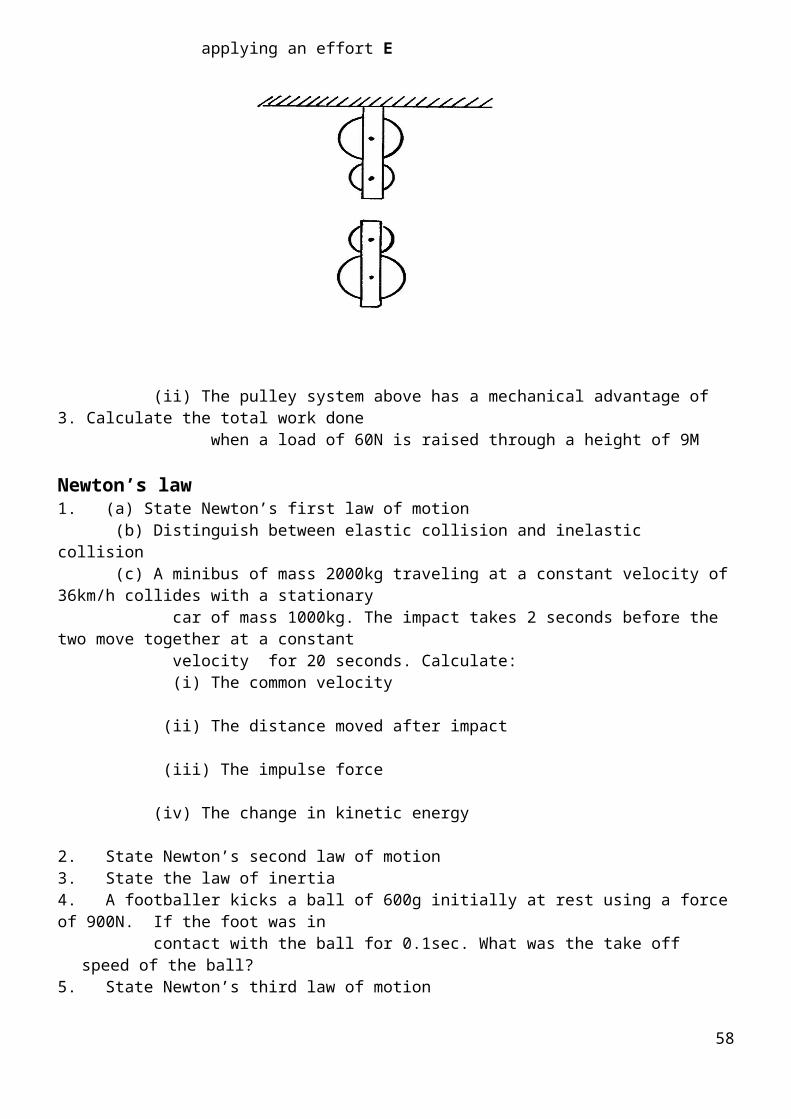
8. Pressure due to kerosene = òK hkg= 800 x 0.1 x 10 = 800p.aÖ1
Pressure due to water = w hwg= 1000 x 0.2 x 10 = 2000p.aÖ1
Atmospheric pressure = 103,000p.aTotal pressure = 800 + 2000 + 103000
= 105800 p.aÖ1
9. Pressure applied at one pat in a liquid is transmitted equally to all other parts of the enclosed liquid.
10 . Elastic PE = ½ Fe = ½ x 1.5 x 0.01; = 7.5 x 10⁻³ J;
11. Pressure on = Lfg; Solid at c = (0.02 x 1000 x 10) + (0.04 x 800 x 10); = 200 + 320 = 520N/m2 ;
12. Difference in the level of water should be 20cm
13. Pressure of the gas = Atmospheric pressure + ehg; = 1.0 x 10⁵ + 20 x 1000 x 10 100
= 1.0 x 10⁵ + 2.0 x 10³Nm-2
= 1.02 x 10⁵Pa;14. - Rubber is elastic; and when a nail is pushed through it stretches and grips firmly the nail
without allowing air leakage;or – Valve effect pressure from inside causes tyre rubber to press firmly on the nail;
15. (a) – Increasing the force (weight)(b) Slanting sides increase the area supporting the weight of the liquid, hence its effect on the bottom of the container
17. In the narrow section of the funnel, air moves with high velocity hence followed by 10N pressure and when they emerge into the wider section, they spread, hence more min-low velocity resulting to high pressure. The high pressure below the ball lifts the ball up to the neck of the funnel.
18. Max pressure = Force/ Min Area Ö 1= 3N/ 0.1 X 0.05Ö1= 600N/m2 Ö 1
19. (a) – Incompressible – Not corrosive – Has low freezing point and high boiling point (any one)
20. h1p1g = h2p2g h2 = h1p1
p2
= 0.7 x 13600Kg/m 3 1000kgm-3
= 9.52m
58
P1
P1
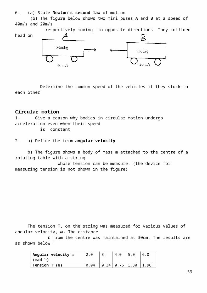
21. Pressure = Force Area
= 2500 4 x 0.025 = 250,000Pa
22. a) i) Atmospheric pressure 1.05 x 10⁵N/M2
ii) Any water vapour available is near its condensing point. Intermolecular forces are therefore appreciable Ö, so it does not behave like an ideal gas
iii) - Fix a millimeter scale to read the length ( L) of air column B Ö and the difference in height (h) between the levels A and CÖ- Adjust the level of C by adding more mercury a little at a time and record the
corresponding values of L and h each time Ö - A graph of L against h represents Boyle’s law Ö
(b) i) Increase in temperature causes gas molecules to move faster(increases in kinetic energy), Ö hence they generate greater/ higher impulsive force on impact Ö
ii) With increase in volume gas molecules are sparsely spaced Ö so the rate of collision is reduced/ lowered
Current I 1. (a) natural convection – involves change in density of the fluid with temperature, whereas forced convection involves the mixing of hot and cold part of the fluid though some
external stirring, like a fan or pump (2mks)
‘ (c) (i) Copper is a good conductor of heat; hence water gets warmed faster(ii) The glass cover does not allow the radiant heat form inside the panel to escape since this heat as lower energy than that from the sun. This heat continues being trapped inside and the temperature increases, thus boosting the heating of the eater
Particulate nature of matter1. (a) The kinetic theory of matter states that matter is made up of tiny particles which are in a
constant random motion (b) – Gas particles have low cohesive forces - Gas particles have high kinetic energy
59

- Gas particles have low density,
(c) (i)
(ii) Experiment procedure- A long glass tube is clamped horizontally as sown in the figure below- A piece of cotton wool is soaked n concentrated solution of hydrochloric acid and another in con-
centrated ammonia solution- Simultaneously, the soaked cotton wool pieces are inserted at the opposite ends of the horizontal
glass tube and cork.- Observations are the noted
(iii) Possible observation (1mk for correct observation)o A white deposit of ammonium chloride forms on the walls on the walls of the glass tube in
the region nearer end BConclusion (1mk for correct conclusion)- Different gases have different rates f diffusion
2. Gases have weaker (small) intermolecular forces while while have relatively stronger (bigger) intermolecular forces p1mkOr Water has stronger intermolecular forces than gases. p1 mk
3. Brownian motion in liquids and gases4. The rare of change of momentum of a body is directly proportional to the resultant external force producing the change and acts in the direction of the force5. The K. E of the smoke particles reduce and hence their movements will be slower (reduces )6. The silver coating Ö 1 on the inner surfaces of the double walled glass
7. (a) The balloon expands (increases in volume) - Evaluation reduces air pressure in the bell jar. Reduction on pressure in the jar leads to expansion of air in balloon
(b) (i) Hydrogen gas diffuses faster into the porous pot mixing with air initially in the pot, this increases pressure in the pot causing air to move out through the tube forming bubbles.
(ii) Hydrogen gas diffuses faster out of the pot. This reduces the gas pressure inside the pot hence higher atmospheric pressure on the surface of water in the beaker to push water up the glass tube.
(c) (i) P1V1 = P2V2
P1L1 = P2L2
P1 = 750mmHg, P2 = (750 + 50) = 800mmHg L1 = 40mm 750 x 40 = 800 x L2
L2 = 750 x 40 800 = 37.5mm
60P1
P1
P1
P1
P1P1
P1P1
P1

(ii) The pressure on trapped air is higher when the tube is vertical than when it is horizontal Increase in pressure lead to reduction in volume in order to increase the number of collisions per unit time between the air particle and the alls of the glass. This increases the air pressure to balance the increased external pressure.
8. Diffusion is faster in vacuum Ö 1 since there are no air particles to interfere with motionÖ 1
9. Energetic molecules gain heat energy from the substance in which the liquid is in contactand escapes. This causes cooling of the latter
10. (a) (i) Air molecules/particles which were in a state of continuous random motion collided with smoke particles
(ii) They are light hence move significantly when bombarded by air molecules (iii) There would be increased rate of movement(b) (i) Volume of oil drops = volume f patch
4 R3 = d 2 t t = thickness3 44 x (7 x 10-4)3
3 2= (0.75)2 t
45.7166 x 10-11 = 0.1406t
Thickness, t = 5.7166 x 10 -11 0.1406
= 4.066 x 10⁻¹⁰m (accept other units other than metres(b) (ii) Assumptions- Oil drop forms a perfect sphere (1mk)
- Patch formed is a perfect circle (1mk) (any 2)
11. The particles making up gases are further apart than those in liquids ÖThermal expansion
1.
- The beam expands linearly - The beam remains straight but longer than before heating- Both concrete and steel have same rates of expansion- Their value of linear expansivity is 11x10-6
2. a) – Alcohol. p1 mk- Mercury. p1 mk
b) i) below -40oc alcohol p½ because it has a low freezing point of –115oc. Mercury freezes p ½ at -39oc. ii) 150oc mercury p½ because it has a high boiling point of 357o, alcohol boils at 78oc. p ½3. - This is the temperature of pure melting ice at standard/normal atmospheric pressure;
(Both pure and standard pressure mentioned;4. - Using a thin walled bulb Ö1
- Using a narrower capillary tube Ö15. On cooling, the brass contracts more than iron, hence become shorter than iron and forms up-
wards curve, making the marble to roll and settle at the centre of the curve.
6.
61
P1
P1
P1
Steel
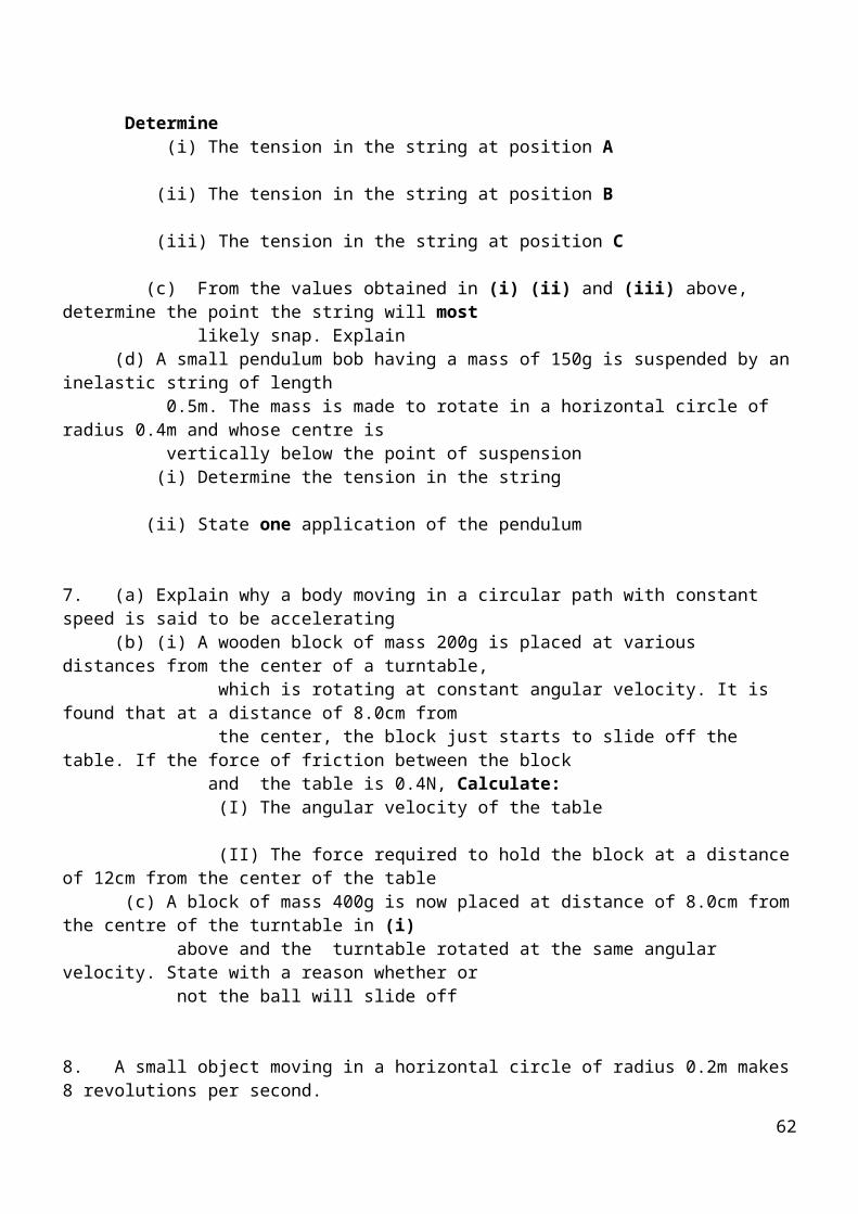
Measurement II1. a)Exact diameter reading – 0.11
b) Find the density of the ball bearing giving your answer correct to three significant figures V = 4 p D 3
3 Z
P = m/v2. Determine the extension of the system
6N purchase 2cm extension50N = 2X50 = 16.667 cm 33.33 6 8.33Total extension = 16.667X2 + 16.667 41.66 cm Z
3. Water in a dam falls through a height 24.5m. If we assume that there are no energy losses, calcu-late the new temperature of the water as it strikes the lower end, given that its initial temperature at the top of the dam is 18.9°C.Take specific heat capacity of water = 4200Jkg -1 KY
mhg = mCDq 24.5 X 1Ø= 420Øj/kg k X (q -18.9)24.5 = q - 18.9420q = 18.95830c or k
4. The powder around the hot needle moves away.Reason The high temperature of the needle lowers the surface tension of the water around it. High surface tension on the sided pits the powder away
5. (a) (i) Volume of one drop = 26.00 – 25.2 50 = 0.8 = 0.016cm3
50(ii) Thickness of oil molecule = vol. of drop
Area of drop = 0.016 3.142 x 3.5 x 3.5= 4.15 x 10⁻⁴cm
(iii) – The patch is even- Oil drop forms a monolayer
(iv) – To show the circular patch formed by the oil drop(b) Vol. of molecule = 1.5 x 10-9 x 0.6 x 10-9 x 0.6 x 10-9
= 0.54 x 10-27 = 5.4 x 10⁻²⁸m3
1 litre = 1000cm3
= 1.0 x 10⁻³ m3
No. of molecules in 1litre = 1.0 x 10 -3 5.4 x 10-28
= 0.18515 x 1025
= 1.8519 x 1024 molecules
5. -ve error is added 5.990.06
62
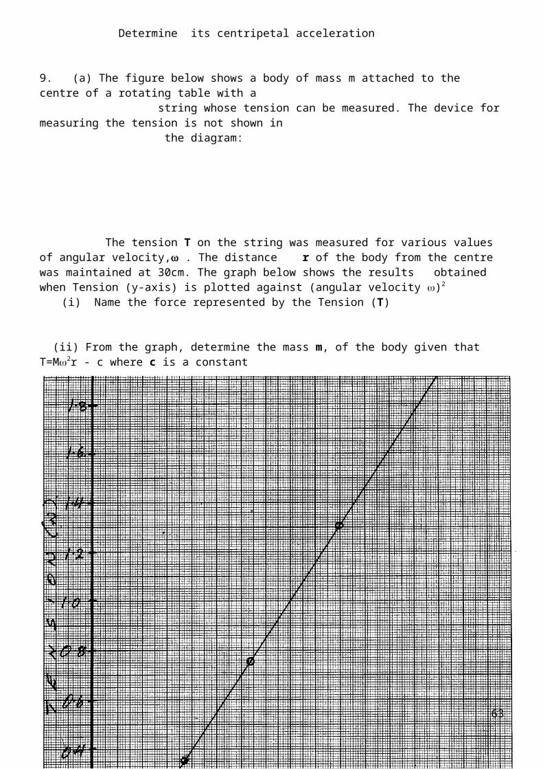
6.05mm
6. Actual reading = 3.21 + 0.06; = 3.27cm;
of 0.5mm
7. (i) Reading = actual reading = zero error= 2.32mm + -0.01
= 2.31mm (1mk)
8.
9. Reading, mass = 2.75KgÖ 1Density = mass/volume = 2.75Kg/3x10-4m3 Ö 1
= 9.167 x 10³Kg/m3Ö1
= 9167Kg/m3
10. Main scale reading = 3.1cm = 3.1cm Vernier scale reading = (4x 0.01) = 0.04cm Diameter f the marble = 3.13 x 10⁻²m
11. Volume of the marble = 4/3pr3
= 4 x 3.14 x 1.565 x 1.565 x 1.565 x 10-6
= 10.0476 x 10⁻⁶m3
Mass of the marble = 2.0 x 10⁻³kgDensity of the disc = mass
volume = 2.0 x 10 -3 16.0476 x 10-6
= 0.1246 x 103
= 12.46 x 10²Kg/m3
12 ½ X 3 Ö = 1.5cm Ö 1
13. a) Volume of drop = 4/3 r3
V = 4/3 X 22/7 X (1.36/1000)3 Ö 1= 1.054 X 10⁸m3
b) 4/3r3 = R 2tÖ1t= 4/3 X (1.36 X 10 -3)3
(4.0 X 10⁻¹) 2 Ö1t = 4/3 X 1.36 3 X 10 -9
4.02 X 10-2
= 0.2096 X 10⁻⁷
63
P1
P1
P1
P1
= 2.096 X 10⁻⁸m Ö 1 3 mks
c) Lycopodium powder makes the film outline clearly visible Ö 1 1 Mk
d) - The film/ patch is a perfect circle- The film is a monolayer- There is no space between the molecules An
14. Zero error + 0.04Reading diameter = 0.93 – 0.04
15. Main scale = 5.5mm Head scale coincidence = 23mm
100Reading = 5.50
- 0.23 5.73mmActual reading = 5.73mm – 0.01mm = 5.72mm
16. a ward 1m for the correct diagram showing the correct reading. p1 No mark if the student uses 50 disks on the thimble scale.
Turning effect of a force1. Sum of clockwise moments = sum of anticlockwise moments 60cm x 200g + 50cm x Mg = 40cm x 400g *TEZ* 12000cmg + 50mcmg = 16000cmg 50Mcmg = 4000cmg 50M = 4000 M = 4000 = 80g 50 w = 0.8N
2. Calculate the force F1 40 X 5 = f X 60 + 3 X 10 200 = 60F + 3060 F = 170 F = 170 60 = 2.833N
3. (a) Balloon and air will expand therefore up thrust on balloon increases thus clockwise moment increases (c) (ii) Volume under water = ¾ x 40,000
64
P1P1

= 30,000cm3
4. For a system in equilibrium the sum of clockwise moments about a point is equal to the sum of anticlockwise moments about the same point;
5.
0.8 x 2.5 = d x10 d = (0.8 x 25) = 2.0 (1mk) 10
length = (0.8 + 2) 2 = 5.6cm (1mk)
6. actm = ctm x(0.3) + 2.0 x 0.1 = (30 x 0.2) + 2 x 0.1 0.3x = 6.2 – 2.0 x = 14N
7. Clockwise moments = Anticlockwise moments1.5 X 0.1 = W X 0.15 Ö
W = 0.15/0.15
W= 1N Ö
Equilibrium and centre of gravity
1. a) This is the point of application of the resultant gravitational force on a body. Appoint at which the weight of the body seems to cut
b) The figure below shows a wine glassState how the stability of the glass is affected if it is filled with wine
The glass becomes more unstable since the c.o g is now raised
2. - Stability reduces /is lowered/becomes deny unstable less; - position of C.D.C is raised / there is more mass at the atop; (Deny unstable)
3. - Increasing the base area/ making base heavier Ö1- Increasing COG/ making base heavierÖ1
4. 10w + (1.0 x 6.0) = 2.0 x 40Ö110w + 60 = 80
W= 20/10 = 2NÖ15. It remains vertical because the shape generated by the rotation is always symmetric, so its centre
of gravity falls directly above the point of support. It therefore remains vertical for sometime.
6. As the wine fills the glass, the centre of gravity rises and this lowers the stability Ö 1
7. Bisect any two sides and join the bisector to the apex where lines meet if the C.O.G
8. Clockwise Moment = Anticlockwise Moment 20 x 30 = 30(f + s) 600 = 30f + 150
30F = 450 F = 15NÖ
Fluid flow
65
P
P1P1
P1
P1
P1
1.
2. The sum of potential energy, kinetic energy and pressure per unit volume of non-viscous fluid flowing is constant
3. A1V1 = A2V2; 7 x 5 = 21 x V2; V2 = 1.667m/s;
4.
5. (i) For a non-viscous, non compressible fluid, in continuous flow, the pressure at any part of it is inversely proportional to the velocity of the fluid (1mk)
(ii) The gas jets in the barrel reduces pressure in the barrel hence the higher atmospheric pres-sure outside the barrel pushes air though the hole
6. Air flows over the top faster than air flow underneath; so air pressure on the top is less than air pressure underneath Ö1
The difference in pressure causes the lift effectÖ1
7. High speed of air reduces pressure above the mouth of the container Ö1 higher pressure below the body pushes it up
8. Volume flux = Velocity x cross-sectional area= 5mls x 3.142 x 10-4m2
= 1.571 x 10⁻³m/s
Hook’s law
66
P1

1.
(c) slope = 0.16 – 0.05 = 0.11 = 0.02683 6.0 – 1.9 4.1
Spring constant = 1 0.02683 = 37.27Nm-1
(e) – Force - Acceleration
2.
3. F1 = Ke1 = 40 = Ke1
e1 = 40 KF2 = Ke2 = 20 = Ke2
K Ke2 = 20
Kbut e1 + e2 = 20
67P1
Mass attached (kg) 0.15 0.30 0.45 0.60 0.75 0.90 1.05 1.20Force (load) on the spring(N) 1.5 3.0 4.5 6.0 7.5 9.0 10.5 12.0Extension of spring (m) 0.04 0.08 0.12 0.16 0.20 0.25 0.30 0.34
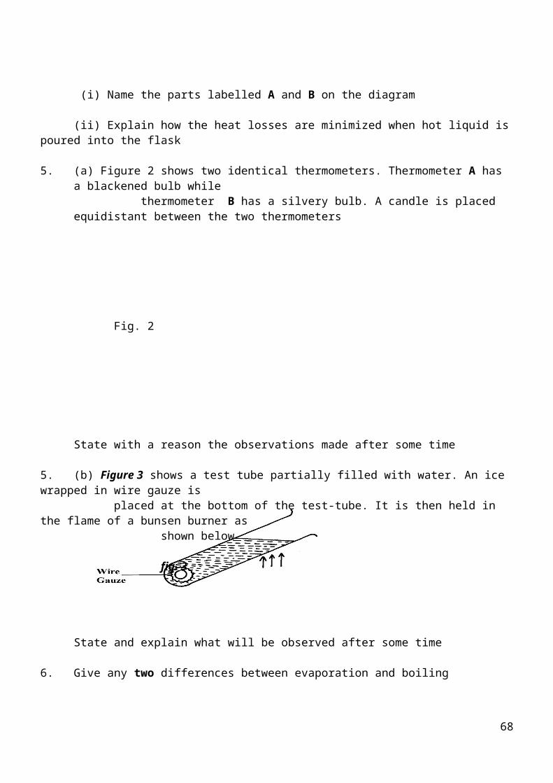
1
40 + 20 = 20cmK K60 = 20kK = 3N/cm
4. Diameter of coils/ Thickness/ No. of turns per unit length / length of spring are different Ö1
5. Upper springs, e = 3.6 3
Middle springs , e = 3.6 = 18cm 2
Lower springs, e = 3.6 = 3.6cm 1
Total extension = 1.2 + 1.8 + 3.6 = 6.6cm
6. a) Load on each spring = 60/3
= 20NÖ Extension (e) in one spring = F/K Ö for one spring
= 20/50
= 0.4m Öb) The effective constant (K)
= K1 + K2 + K3Ö= 3(50)= 150N/M Ö
7. A load of (25 – 20)N causes extension of (17 – 15) cm.i.e. 5N causes extension of 2 cm p120N = ?20 N x 2 cm = 8 cm p1
5 N
When no mass is hung.Length of the spring = 15cm – 8ch
= 7 cm p1
a) Uniform velocity :- The change in displacement for equal time intervals is the same.Uniform acceleration:- Change in velocity for equal time intervals is the same.
b) Determine the acceleration of the trolley pulling the tape
Va = 2 = 100cm/s Vb = 3 = 150 cm/s a = V-U 0.02 0.02 t = (150 -100)/ (7X0.02 – 0.02) a = 416.67 cm/s2
c) i) Determine the motion of the ball relating it to its different positions along the followingI AB the body is projected upwards and at B V = OII BC the body falls back to the starting point (moving in the opposite direction)III CE the body be rebounds on the ground (at starting point) and starts moving up again
ii) From the graph calculate the acceleration due to gravity a = v-u a = -10m/s2
t = 10m/s2
= 0-20 2
68
P1
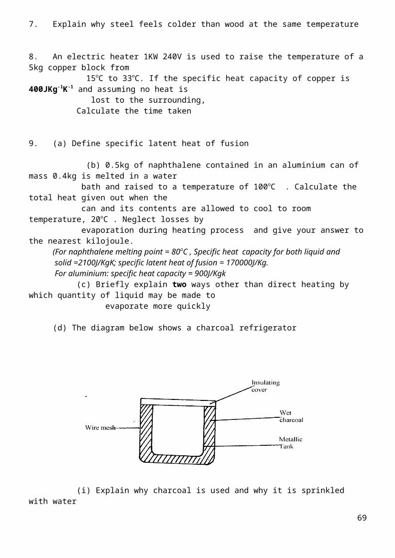
Linear motion1. a) Uniform velocity :- The change in displacement for equal time intervals is the same.
Uniform acceleration:- Change in velocity for equal time intervals is the same. b) Determine the acceleration of the trolley pulling the tape
Va = 2 = 100cm/s Vb = 3 = 150 cm/s a = V-U 0.02 0.02 t = (150 -100)/ (7X0.02 – 0.02) a = 416.67 cm/s2
c) i) Determine the motion of the ball relating it to its different positions along the followingI AB the body is projected upwards and at B V = OII BC the body falls back to the starting point (moving in the opposite direction)III CE the body be rebounds on the ground (at starting point) and starts moving up again
ii) From the graph calculate the acceleration due to gravity a = v-u a = -10m/s2
t = 10m/s2
= 0-20 2
2. ConductionFree electrons at the heated and gain more kinetic energy and spread the heat energy to other parts of the rod
3. (a) Momentum before collision = momentum after collision150 x 80 = 2.65 x V100016 = 2.65VV = 16
2.65 = 6.0377
But ½ mV2 = mgh h = V 2 = (6.0377) 2g 2 x10
h = 36.4538 20
= 1.82269m(b)The block will be deformed
4. Total distance = Area under graph; = ½ (12 + 5) x 20; OR = 170m;
Average speed = 170m 12s = 14.17m/s;5.
6. (i) Acts as a thermostat69
P1

(ii) On closing, the switch, current becomes complete, the current flows causing heating effect, the bimetallic strip bends downwards and contents separates. when the room becomes cool the strip bends upward completing the current and the process repeats itself on and off regulating the temperature- Weight of the fluid in which it floats
7. Clockwise moments = anticlockwise moments at equilibrium 0.6 x 0.7 = W x 0.3;
W = 0.6 x 0.7 0.3= 1.4N;
0.6 + R = 1.4 R = 0.8N;
8. (a) Length = area under curve = 10 x (32-18);
= 10 x 14 = 140m;(b) 10-25 = -15; = -1.875ms-1
18-10 8 Decal = 1.875ms-1;
(c)(i)
(ii) Keep the train in circular motion; (iii) Friction force between the wheels and rails;
(d) (i) F = m(v-u) t
= 90(0-45); 1.2
= -3375N;
(ii) Kinetic energy – Heat + sound + P.E(deformation;
(iii) E = ½ Mv2;= ½ x 90 x 45s;= 91,125J;
9. (a) (i) When a body is projected vertically upwards, it under goes a uniform retardation due to the gravitational pull. The body thus slows down, comes to rest them starts falling with an
increasing velocity (in opposite direction) (ii) Acc of free fall = gradient / slope of the graph
= 5 - 0 = 5 = 1.66ms-2
3 - 0 3 (iii) Total distance = Area under the curve
(½ x 5 x 3) +(½ x 2 x 3.3.) 15 + 10 = 30 + 20 = 50 = 25 = 8 1/3m 2 3 6 6 3 (iv) - Wt in the moon = mg = 2kg x 5/3 = 10/3 = 31/3N (v) - It will accelerate faster at 10ms-1 from the graph - It will attain a maximum height after ½ second
(b) V1 = 1.5cm = 75cms-1 = V2 = 3.0cm = 150cms-1
0.025 0.02s a = V2 – V1 = 150 – 75 = 75 = 937.5cm-2 or 9.375ms-2
70
PP

t 0.02 x 4 0.08 S = ut + ½ ast2
= (0.75 x 4) + ½ x 9.375 x 42 = 3 + 75 = 78m
10. a) The volume of a fixed mass of gas is inversely proportional to its pressure provided temperature is kept constant.(b) (i) The bubble expands as it comes up finally bursts when at the surface
(ii) p1V1 = P2V2
(76 + 30) x 3 = (76 + 5) V2
106 x3 = 81 X V2
V2 = 106 x 3 81
= 3.93cm3
(c) 100oC - 0oC = 98 -111 division = 87
100Reading = 8 x 56
1000 = 48.72oC
11. Distance traveledÖ1
12. a) A body continues with its state of rest or uniform motion unless acted upon by some external forcesÖ1
b) i) s = ½ gt2
720 = ½ x 10 x t2Ö1 t2 = 144t= √144 = 12 sec Ö1
ii) Range = ut= 120 x 12Ö1 = 1440m Ö1
c) i) – Centripetal force acting on M1 Ö1 - Weight (M2g) acting on M2Ö1 ii) M2 moves upwards; Ö1 When the speed of M1 increases centripetal force remains the same, the radius of the
circle described by M1 increasesÖ1 iii) Centripetal force = weight of M2
M1V2/r = M2g0.020 V2/1 = 0.050 x 10Ö1 V2 = 0.5/0.02 = 25Ö1 V= √ 25 = 5m/s√1
13. (a) Constant rate of change of displacement with timeOR- A body is said to be moving with uniform velocity it its rate of change of displacement with time is constant(b) (i) For one correct tangent
Velocity t = 1s = 42 - 20 2 – 0.5 (correct reading form graph and expression = 14.67m/s
Velocity at t = 4s = 67.5 – 3071
P1
P1
P1
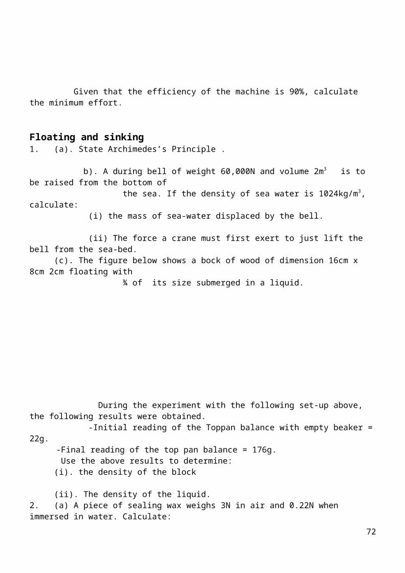
5 – 0.5 (correct reading from graph ad expression) = 8.33m/s (accuracy)
(ii) a = V – u = 8.33 – 14.67 = 6.34 t 4-1 3 = 2.11m/s2
14. S = ½ gt2 since u = 0= ½ x 10 x 4 x 4 = 80m
15. b) i) t = v – u Ö g= 0 – 60 Ö -10= 6 secs Ö
ii) h = ut – ½ gt2 Ö= 60 x 6 – ½ x 10 x 62 Ö= 360 – 180= 180mÖ
iii) V2 = U2 + 2aSÖ O = U2 + 2 x -10 x 5Ö O = U2 – 100
U = 10m/sÖc) Resistance/ friction with air is negligible
16. a) Length of nine dots = 6.9cmÖ Time taken = 1/50 x 9 = 0.02 x 9
= 0.185Ö Velocity = 6.9cm
0.18sÖ= 38cm/s or 0.38m/s Ö
b) Ft = 0.8 x 0.5 – 0.8 x 0.38 Ö Ft = 0.096 F = 0.096
0.18 = 0.533N
17. a) Equations of linear motion. i) V = u + at. p1 ii) V2 = u2 + 2as p1 iii) S = ut + ½ at2. p1
b) 100 km/h x 10 = 27.78m/s 36 In 0.5 sec the driver covers 27.78m/s x 0.55 = 13.89 M p1
After applying brake a = -4m/s2
u = 27.78m/s. v= 0
∴ v2 = u2 + 2as p1 - 2as = u2. since v = 0
S = u2 = (27.78m/s)2 = 96.47M p1 -2a (-2) (-4m/s2) Total distance covered = (13.89 + 96.476)M = 110.36 Mp1
72
P1
P1P1
P1
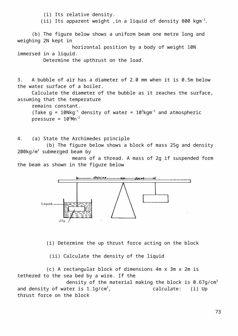
c) (i) See the graph paper (ii) (i) Average speed of the whole journey = Total distance covered Total time taken Distance = Area under the graph = (20m/s x 50s) + (½ (20 + 25) x 10) + ½ (50 + 65) x 25 = 1000m + 225m + 1437.5m = 2662.5m p1 Total time = 125s Speed = 2662.5 = 21.3 m/s p1 125s = 21.3 m/s p1 (ii) a = v-u t = (25 – 20) m/s p1 10 s = 0.5m/s2 p1
18.
Machines & inclined planes1. M.A = 600M = 0.92307 650M
V.R = 1 = 2.366 Sin 25 h= M.A = X 100 V.R
= 0.92307 X100 2.366 = 39.01%2. (a) V.R = 5
(b) MA = L E = 4000 1000 = 4
(c) eff. = M.A x 100% VR = 4/5
= 80%(d) Some work is done overcoming friction or lifting the moving parts
(e) W = F x d = 40,000 x 0.05 = 2000J
3. VR = 4A = L = 100
73
PP
PP
PP
P PP

E 48\u = M.A x 100%
V.R= 100 x ¼ = 52.08%
48
4. (a) (i) Velocity ration is the distance moved by the effort to the distance moved by the load in the same time
(ii) - Pulley belts - Gears (any one)
(b) Graph(c) (i) V.R = R 2 = 7x 7 = 25
r2 1.4 x 1.4Efficiency = M.A x 100%
V.RM.A = r x V.R = 80 x 25 = 20
100E = KL = 100 x 10 = 50N
M.A 20 (ii) EH = work output x 100% Work input Work output =mgh
= 100 x 10 x 2.5= 2500J
80 = 2500 x 100 Work output
Work out put = 2500 x 100 = 3125J 80
Energy lost = 3125 – 2500 = 625J
5. i)
ii) E = L/M.A
= 60/3
= 20N ÖTotal work done by effort
= E x Distance moved by effort Ö= 20 x 9 x V.R= 20 x 9 x 4= 720J Ö
74
1
25
Newton’s law1. (a) Newton’s first law:
- A body remains in its state of rest or uniform motion in a straight line unless acted upon by an external force *TEZ*
(b) Elastic collision is one in which both kinetic energy and momentum are conserved, while inelastic collision is one in which momentum is conserved, but kinetic energy is not (2mks)
(c) Momentum before collision = momentum after collision 1mk) (2000 x 10) + (1000 x 0) = (2000 + 1000)V 3000V = 20000 V= 62/3m/s
(ii) d = Velocity x time *TEZ* = 20 x 20 = 400m = 1331/3m 3 3
(iii) Impulse = change in momentum = 2000 (10-62/3m/s) – for the minibus Or= 1000 (62/3m/s-0) – for the car = 6667NS
Impulse of force = Impulse Time = 6667 = 3333.5N 2
(iv) K.E before collision = ½ x 2000 x 102 = 100,000J K.E after collision = ½ x 3000 x (62/3)2 = 66,666.7J Change in K.E = (100,000 – 66666.7) J
= 33,333.3J 2. The rate of change of momentum is directly proportional to the external force acting on a
body it is in the direction of force3. A body continues in its initial state rest or uniform motion unless compelled by an external force to make it behave differently.4. F = Ma
900 = 600a 100 a = 9000 = 900ms-2 (1mk)
10but a = v-u
t at = v-u
(900 x 0.1) = v = 90ms-1 (1mk)
5. For every action there is an equal and opposite reactionÖ 16. (a) The rate of change of momentum of a body is directly proportional to the resultant external force producing the change and takes place in e direction of force.
(b) m1u1 – m2u 2 = (m1 + m2) V = m1u 1 – m2u2
M1 + m2
= (2500 x 40) – (3500 x 20)2500 + 3500
= 30000 6000 = 5ms-1
Circular motion1. The direction of the speed keeps changing hence the velocity at each point on the circular path
is given by the tangent to the path at that point2. a)This is the rate of change of angular displacement with pimp. b) The tension T, on the string was measured for various values of angular velocity, რ. The
75
P1P1
P1

distance r from the centre was maintained at 30cm. The results are as shown below
Angular velocity რ (rad s-1) 2.0 3.0 4.0 5.0 6.0
Tension T (N) 0.04 0.34 0.76 1.30 1.96W2 (rads
-2) 4 Q 16 25 36i) Plot the graph of T (y – axis) againstრ2
ii) From the graph, determine the mass, m, of the body given that T = რ2 r – CWhere C is a constant
Gradient = Mr M = gradientGradient = 0.76 – 0.04 r
16 -4 = 0.06 = 0.6 = 0.2 kg = 0.06 N|(rad 21-2) 30/100 3
iii) Determine the constant C and suggest what it represents in the set up C is the Y –intercept
C = - 0.2 N3. (a) It keeps changing direction and hence must experience centripetal acceleration
(b) (i) f = 0.5HZ T = 1/f
= 1 0.5 = 2sec
(ii) w = 2 p ; T = 2 x 3.142 2 = 3.142 / sec;
(iii) V = rw ;or = 6 x 3.12 = 18.852m/s
(iv) F = MV 2 r = 30 x (18.852)2
6 = 1776.99N
OR F = mrw2
= 30 x 6 x (3.142)2 = 1776.99N (c) Graph (iii) centrifugal
5. (a) (i) The direction of the particle is tangential to the path of any given point. There is instantaneous change in direction of velocity, this causes acceleration of the particle.
(ii) F = mV2
r = 1.5 x 10 3 x 10 x 10 20 = 7.5 x 10³N
(b) (i) The value of r increases. Increase in speed leads to increase in centripetal force on the bob. This leads to increase in radius of path (centripetal force is directly proportional to radius)
76P1
P1P1 P1
P1
P1
P1
P1
(c)The cyclist leans inwards in order to have enough component of the conact force to provide adequate centripetal force.
6. a) The rate of change of angular displacement with time Ö 1
b) i) TA = mv2/r – mg Ö 1= 0.2 X 5 2 - 2.0 Ö 1 0.5 = 8N Ö 1
ii) TB = mv2/r
= 0.2 X 5 2 0.5 = 10N Ö 1
iii) TC = Mv2 + mg Ö 1= 0.2 X 5 2 + 2 Ö 1
0.5 = 12 N Ö 1
c) At point C where tension is maximum Ö 1
d) i) T cos Q = mg Ö 1 T (0.3/0.5) = 1.5 T= 2.5 NÖ 1 T cos Q = 150/1000 X 10 Ö 1 T = 1.5 X 5
3T cos Q = 1.5 ii) Speed governorÖ 1
7. (a) The direction of its velocity is continuously changing (1mk) (b) (i) Fr = mw2r (1mk)
0.4 = 0.2 x w2 x 0.08w2 = 0.4
0.2 x 0.08 (1mk)w2=25 and 25-2
w =5 rad 6-1 (1mk)
(ii) F =mw2r =0.2 x 5 x5x0.12 = 0.6N (must be shown(c) The block will slide (1mk)
Frictional force (0.4N) is less than the force required to maintain it in uniform circle (1mk)8. µ= rw2 = 0.2(16 p)2 Ö
= 505.3m/s2Ö 9. a) i) Centrifugal force Ö
ii) The gradient of the graph = mass x radius Ö T = MW2r – C From Mr = gradient
Mr = 1.30 – 0.76 = 0.06 Ö25 – 16
Mr = 0.06M x 0.3 = 0.06ÖM = 0.06 = 0.2kgÖ
0.3
iii) y – intercept = -0.2N-0.2 = -C0.2= CÖ
77
P1
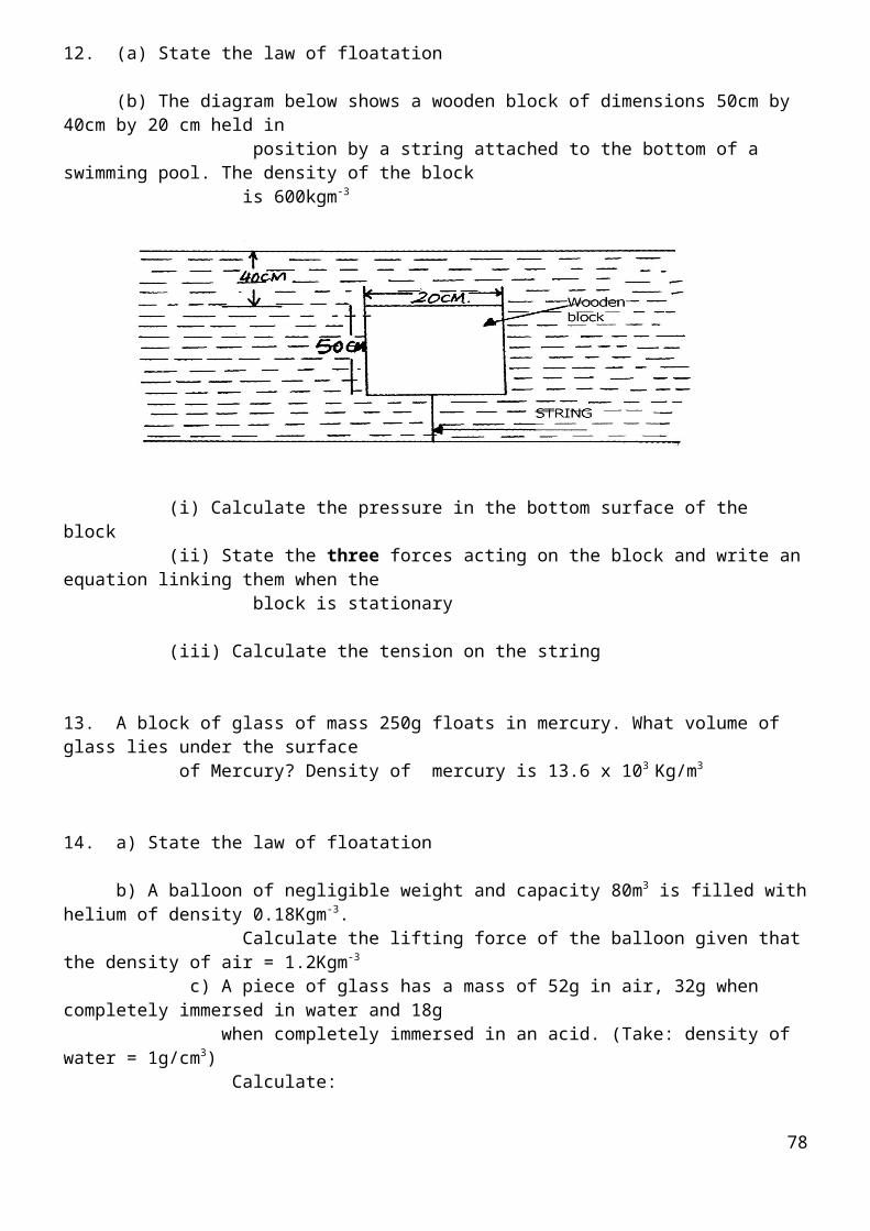
Frictional forceÖ
10. (a) at the highest point of the circle T = Mv 2 - mg r Mv2 = Fe = MW2R R
∴ T = Mw2r – mg But w = 2pf p1 mk
T = (2p x 10)2 x 2kg x 0.5) – (2 x 10) = 400p2 – 20 = 3927.84 N p1 mk
b) T at the lowest point T = Fe + Mg = Mw2r + Mg = 400p2 + 20 = 3967.84 N p1 mk
Quality of heat1. a) Specific heat capacity is defined as the quantity of heat required to raise the temperature of a unit mass of a substance by one Kelvin. p1 mk
b) (i) heat gained by calorimeter QE = C∆θ = 400Jk-1 x (34 – 20)k p1 = 560j p1
(ii) Heat gained by water QW= MC∆θ = 200 kg x 4200kg-1k-1 x(34 – 20)k = 11760j p1 (iii) Heat lost by the metal = heat gained by the calorimeter + heat gained by Water. = 560j + 11760j = 12320j p1 (iv) Specific heat capacity of the metal. C = Q p1 M∆θ = 12320 j p1 0.3 kg x (100 – 34) = 12320j = 622.22 jkg-1k-1 p1 0.3kg x 66 k2. (a)
Boiling Evaporation- Takes place at constant temperature- Not affected by surface area of liquid expo-
sure- Vigorous, visible process al over the liquid
- Takes place at all temperatures- Increases with increase in surface
area- Slow invisible process at the liquid
surface(each for any two correct)(b) (i) A – Temperature of the solid in increasing; AB- solid is melting;
(ii) Heat supplied = Heat gained p x t = MCDq 200 x 100 = 0.2 x C x 100 20 x 100 = 0.2 x C x (350 – 250)
C= 1000JKg-1 K-1; 78
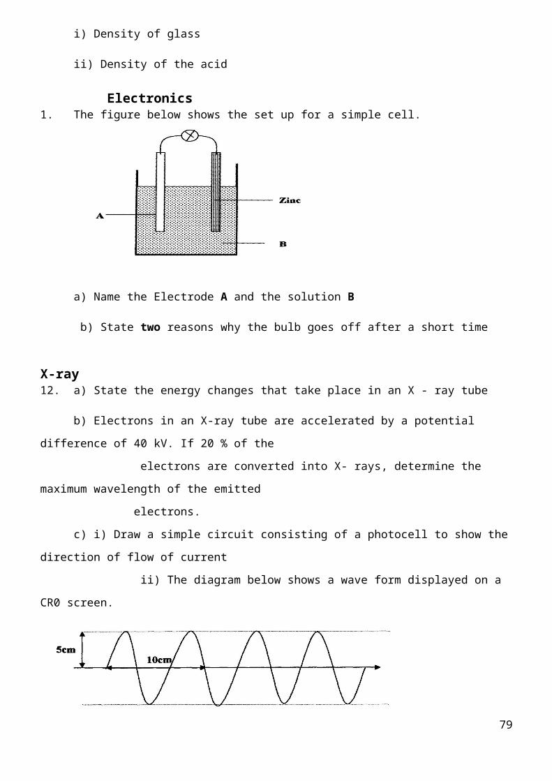
(iii) Heat applied = heat gained; OR p x t = Mlf; 200 x 200 = 0.2 x lf;
lf = 200,000J/Kg; 3. (a) The quantity of heat required to raise the temperature of a given mass of a material by one Kelvin. (b) (i) C = Q q
Q = Cq = 40 x (34-25) = 40 x 9 = 360J
(ii) MwCwD = (0.1 x 9 x 4200) = 3780J
(iii) Heat lost = heat gained by calorimeter + heat gained by water = 3780 + 360 = 4140J or 4.14KJ
(b) 150 x Cm x Dq = 4140 1000 0.15 x (100 – 34) Cm = 4140 9.9C = 4140 Cm = 4140 = 48.18JKg-1K-1
9.9(b)
Boiling Evaporation - Temperature is constant- Affected by impurities and pressure- vigorous with bubbles- takes place in the whole liquid
- Temperature can vary - Not affected with impurities- not vigorous, no bubbles- takes place at the surface
4. (a) Evaporation is change of liquid to gas at any temperature while boiling is change of liquid to gas at constant temperature;
(i) Heat – mlv + MCDq= 0.44 x 2.26 x 106 + 0.44 x 4200 x 100;
1000 1000=994.4 + 184.8 = 1179.2J;
(ii) Q = mLf; t t
= 4.4 x 10-3 x 3.34 x 105= 1336J;
(iii) - Heat is absorbed from the surrounding since the can is unlagged;(c) A = Vacuum;
B = Silvered (shiny) surfaces/polished/smooth;(ii) - Loss of heat by conduction is reduced by cork and vacuum;
- Loss of convection is reduced by vacuum; - Loss by radiation is reduced by silvered wall;
5. Thermometer A gives a higher reading than B; Ö 1 Black surface is better absorber of heat than silvery surfaceÖ1
5. Water at the top part of the boiling tube boils while the ice remains unmelted. This is because water is a poor conductor of heat and hot air less dense remain at the top.6. – Evaporation is silent while boiling is a vigorous visible process - Evaporation takes place at all temperatures while boiling takes place at a specific temperature
- Evaporation takes place on the surface of the liquid but boiling takes place in the whole liquid
7. Steel is a good conductor of heat; therefore draws heat from your body unlike wood
79

which is a poor conductor of heat8. Pt = MCDT DT = 35 – 15 = 18K
T = MCDT= 5kg x 400JKg -1 K -1 18K
1000JS-1
= 36s
9. (a) It is the quantity of heat required to convert a unit mass of the substance from the solid to the liquid state without change of temperature (1mk)Heat lost by naphthaleneT = 100-80=20kH1 = 0.5kg x 2100JKg-1K-1 x 20K = 2100JLf = mLf = 0.5kg x 170000JKg-1 = 85000JT = 80 -20 = 60k , H2 = 0.5kg x 2100JKg-1K-1 x 60k = 63000JHeat lost by aluminium T = 100 – 20 = 80k H = 0.4kg x 900JKg-1K-1 x80k = 28800JTotal heat lost = 169000J + 28800J = 197800J
= 197.8KJ= 198KJ
(c) Blowing wind over the surface of the liquid increases the kinetic energy of the liquid molecules
- It can also be made to evaporate faster by bubbling air though the liquid as it increases the surface area from which the liquid molecules may escape
(d) (i) – Charcoal is a black body and therefore a batter absorber of heat - Sprinkled with water, so that it takes latent heat from the air around the air around and evaporates , causing cooling in cabinet (ii) Heat is conducted by the by the metallic tank and the wire mesh to the surrounding air
10. Loss of heat through radiation is reduced/ minimized Ö
Work, energy and power1. (a) The law of conservation of energy states that the sum of kinetic energy and potential energy
of a system is a constant (b) (i) At P and T potential energy is a maximum and kinetic energy is a minimum. Hence
velocity is zero (2mks) (ii) At Q and S P.E has reduced by 0.1J. This equals the K.E
K.E = ½ MV2
0.1 = ½ x 0.8V2
0.1 = 0.4V2
0.1 = V2
V2 = ¼ = 0.25V = 0.5m/s
(iii) At R, auP.E has been converted to K.E velocity now is a maximumSo, 0.2 = ½ MV2
0.4 = V2
V = 0.4m/sV = 0.64m/s
(c) (i) M.A = L = 280N = 7 (2mks) E 40N (ii) V.R = P = 70 = 14 (2mks) R 5 (iii) n = M.A x 100%
80

V.R = 7 x 100% 14 = 50% (2mks)
2. a) (i) CR = 2 p R = No of teeth draw 2pr No. of teeth of driven p1 ∴ 16.5 cm = 44 r 16 r = 16.5 cm x 16 p1 44 R = 6 cm p1
(ii) V.R. = R p1 r = 16.5 cm p1 6 cm = 2.75 p1
b) (i) M.A. = L 120kg x 10N/kg = 1200N p1
E = 1200N p1 300N = 4 p1
(ii) Its efficiency of: D = M.A x 100% p1 V.R. = 4 x 100% 6 = 66.67% p13. (a) Work is said to be done when the body on which a force is applied moves in the direction
of force; S.I unit if the Joule, J or (Nm);
(b) (i) Work done = P.E gained ; = mgh
= 500 x 4 x 10;= 20,000J;
(ii) Power = work donetime taken
= 20,0008
= 2.5KW ; or (2500 watts);
(iii) Efficiency = work output x100;work input
= 2.5 x 100; 2.8 = 89.29%;
(iv) – Friction between movable parts- Sound due to moving parts- - heat –some of the electrical energy is converted to unnecessary heat
81
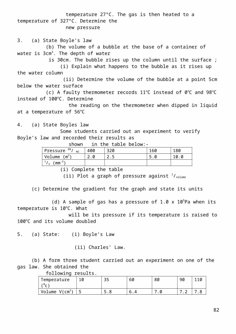
3
w
Floating and sinking1. a)(i) R.d. = Weight of solid Upthrust in water = 3N (3 – 0.22)N p1 = 3 = 1.079 2.78 = 1.079 p1
(ii) Its apparent weight in a liquid of density 800 kgm-3. R.d of the liquid = Upthrust in the liquid Upthrust in water
R.d of the liquid = 800 kgm -3 = 0.8 p1 1000 kgm-3
0.8 = u1
2.78 N u = 2.78 x 0.8 = 2.224 Upthrust u = 2.224N p1 Apparent weight of liquid = weight in air – upthrust in liquid = 3.0-u – 2.224N = 0.776N p1
2. P1VI= P2P2. p1P1 = A + hƍg = 100 000NM-2 + (0.5m x 1000 kgm-3 x 10N/Kg ) p1
P1 = 105000NM-2
P2 = 100 000NM-2 i.e only Atmospheric pressure ∵ Volume is density proportional to R3.
∵ P1r3 = P2R3
R3 = P1r3 = 105000pcx (1x 10-3) P2 100 000 pa p1
R3 = 1.05 x 10⁻⁹ m R =∛1.05 x 10-9 = 1.0164 x 10⁻³m D = 2.0328 x 10⁻³m or 2.0328 mm p1 mk
3. (a) When a body is wholly or partially inversed in a fluid , it experiences an upthrust force equal to the weight of fluid displaced(b) (i) Clockwise moments = anticlockwise moments
0.02N x 0.3 = F x 0.4F = 0.02 x 0.3 = 0.015N
0.4Upthrust = weight –F
=(90.25 – 0.015)N = 0.235N
(ii) Upthrust = weight of liquid displaced = 0.235N
Mass of liquid = weight g = 0.235 = 0.0235kg 10
82

Vol. of liquid = vol. of solid = mass Density = 0.025 = 1.25 x 10⁻⁴kgm-3
200
Density of liquid = Mass of liquid = 0.0235 Vol. of liquid 1.25 x 10-4
= 1880kgm-3
(ii) tension = upthrust – weightWeight = mass x gravitational
= density x volume x gravitational force = 0.167 x 1000x 24 x 10 = 40080
Tension = 264000 – 40080 = 223920N
4. Needle floats in water due to surface tension. Needle sinks when detergent is added because it reduces surface tension
5. c (ii) Volume under water = ¾ x 40,000 = 30,000cm3
6. (a) (i) T = 1/f = 1/100 = 0.01sec;average Vol. u = 0.5 ; = 50cm/s;
0.01(ii) Average Vol. V = 2.5 ; = 250cm/s;
0.01(iii) a = v-u ;
t = 250 – 50 ; 0.01 x 4 = 5000cm/s2 ;
(b) F = ma = 0.5 x 50 N = 25N;
7. (a) When a body is wholly or partially inmmersed in a fluid, it experience and upthrust equal to the weight of the fluid displaced;
(b) (i) Shape;- Space between 1.0 and 1.1 is larger than that between 1.1 and 1.2
(ii) - Law of floatation which states that floating object displaces its own weight.
(c) Upthrust = Weight of fluid = Volume of fluid x density x density x g = Vlg;
8. (a) It is the number of times a substance is denser than an equal amount of water (b) (i) Weight = mass x gravity weight of water displaced p = M V
M = p x V = (800 x 12 x 0.06)
W = Mg = 576Kg x 10 = 5760N
(ii) Upthrust = Weight of liquid displaced= p2 x Vl x g = 1.03 x 103 x 0.06 x 4 x 10 =2472 N
(iii) 5760 – 2472 = 3288N83
P

c (i) (W2 – W3)(ii) R.d = weight of cork in air
weight of equal vol. of water = W2 – W1
W2 – W3
9. (a) A floating body displaces its own weight of the fluid in which it floats(b) The length (x) of block in water increases (block sinks more) . Warm water is lighter; hence the blocks must displace more water in order to balance the same weight of the block
(c) (i) Upthrust – weight of air displaced Volume of air = 200
Mass of air = (200 x 1.2)Weight of air displaced = 200 x 1.2 x 10)
= 2400N
(ii) Resultant upward force= (2400 – 2200) = 200N
wt of 1 rat = 200 x 14 = 2N 1000
(2 x n) = 200 n = 200 = 100 rats 2 10. a) When a body is partially or fully/ wholly immersed in a fluid, it experiences on up thrust which is equal to the weight of the fluid displaced Ö 1 1 Mk
b) i) The measurement of weight registered reduces as the brick is lowered into the water Ö Because of increase in up thrust Ö 1
ii) Up thrust = weight in air – weight in water (apparent weight) = (100 – 80) N = 20N Ö 1
From Archimedes principle 20 = V X S X g Ö 1
V = 20 1000 X 10
V = 2 X 10⁻³m3Ö 1
c) i) To increase sensitivityii) It displaces more liquid that provides an up thrust to make the hydrometer floatiii) To keep the hydrometer upright
11. (a) A floating body displaces its own weight of fluid in which it floats(1mk)(b) (i) p = hpg
= 90 x 1000 x 10 100
= 9000Pa or 900N/M2
(ii) – Upthrust force- Weight
- tension on the string( for alteast 2 correct) Upthrust = weight + tension on the string
(iii) Upthrust = weight + tensionTension = Upthrust – weight = (50 x 40 x 20 x 1000 x 10 ) – ( 50 x 40 x 20 x 600 x 10)
1000000 100000084
P1
P1P1
P1
P1P1
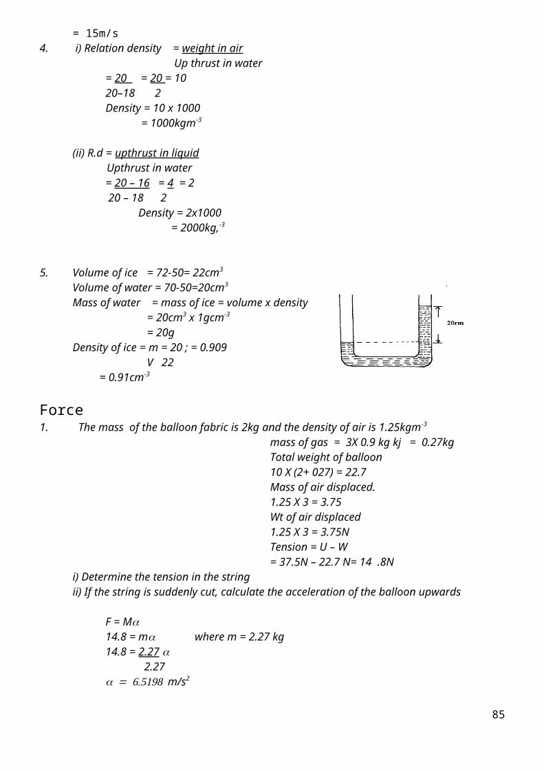
= 400 – 240= 160N12. Weight of glass = weight of mercury displaced
0.25 x g = V x 13.6 x 10³ x g V = 0.25 13.6 x 103 = 1.838 x 10⁻⁵ m3(18.4cm3
13. a) A floating object displaces its own weight of the fluid in which it falls√ 1
b) Up thrust on balloon = weight of air displaced= mg = Pvg= 80m3 x 1.2 Kg/m3 x 10N/Kg= 960N√ 1
Lifting force = Up thrust – weight of helium= 960 – (80 x 0.18 x 10) √ 1= 960 – 144
= 816N√ 1 c) i) Mass of water displaced by glass = 52 – 32 = 20g√ 1
Volume of water displaced = Volume of glass = 20g/1gKm3 = 20cm3 √ 1
ii) Mass of acid displaced by glass = 52 – 18 = 34g√ 1 Volume of acid displaced by glass = 20cm3√ 1 Density of acid = 34g/20cm3 = 1.7g/cm3√ 1
GAS LAWS1. (a) It states that the pressure of a fixed mass of gas is inversely proportional to its volume provided temperature is kept constant (PV = K) (b) P1L1 = P2L2
86 x 5 = 75 x L2
= 5.73cm
(c) (i) When steam condenses, the pressure inside the container will be lower than the atmospheric pressure on the outside. The excess atmospheric pressure acting on the lid exerts a force on the lid thus making it difficult to open the lid.
(ii) The lift pump depends only on atmospheric pressure which can only support a column of water 10m long. The force pump uses force and therefore can lift water to the length greater than 10m.
2. a) Describe how the apparatus may be used to verify pressure law Plotting pressure against absolute temp we get a straight line graph
Conclusion Pressure of infixed mass of a gas indirectly proportional to its absolute to temperature if volume is kept constant
b) i) Given that the relationship between pressure, P and temperature, T in Kelvin is of the form
P = kT + CWhere k and C are constants, determine from the graph, values of k and C
K = gradient = (8-0) X 104 NM -2
200 - 0 K = 400N m-2 K-1
85
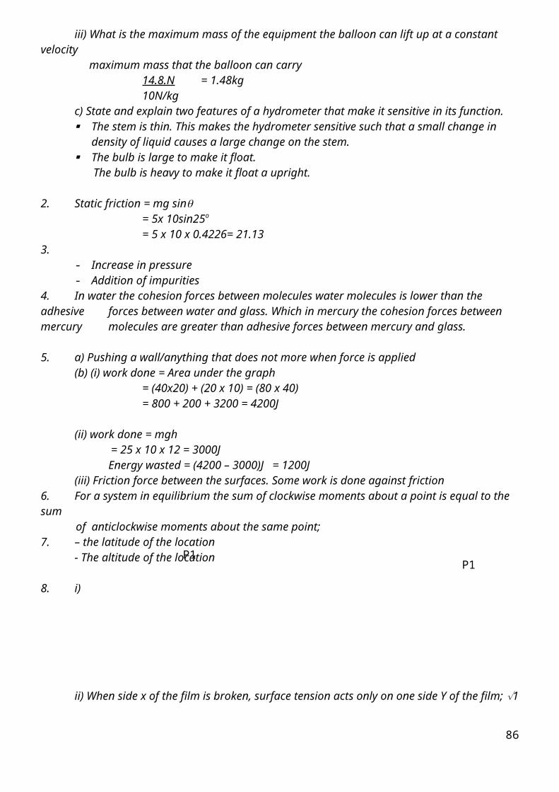
C = O ii) Why would it be possible for pressure of the gas to be reduced to zero in practice?
The gas liquefies at low temperature before reaching zero Kelvinc) A gas is put into a container of fixed volume at a constant volume at a pressure of 2.1 x 10⁵.
Nm-2 and temperature 27°C. The gas is then heated to a temperature of 327°C. Determine the new pressure
P1 = P2 T2 =273 + 327T1 T2 = 600KP1 = 2.1 X 10⁵ Nm-2 P2 = P1 T2
P2 = ? T1 2
T1= 27+ 273 = (2.1 X 6 00 ) X 105NM -2 = 4.2 X10⁵NM-2
= 300K 3003. a) The volume of a fixed mass of gas is inversely proportional to its pressure provided
temperature is kept constant.(b) (i) The bubble expands as it comes up finally bursts when at the surface
(ii) p1V1 = P2V2
(76 + 30) x 3 = (76 + 5) V2
106 x3 = 81 X V2
V2 = 106 x 3 81
= 3.93cm3
(c) 100oC - 0oC = 98 -111 division = 87
100Reading = 8 x 56
1000 = 48.72oC
4. a) The volume of a fixed mass of a gas is inversely proportional to the pressure provided that temperature is kept constant Ö 1
1/v (mm-3) 0.5 0.4 0.2 0.1
b) Labeling the axes Scale Plotting (3,4) pts 2 points Below 2 points Smooth curve / straight line
c) Gradient = Δy Δ x
= 400 – 160 (0.5 – 0.2) X 10-9 Ö 1
= 340 0.3 X 10-9
= 1133.33 X 10-9
= 1.1333 X 10⁻⁶ KNM
d) P1V1 = P2V2
T1 T2 Ö 186

1 X 10 5 X V 1 = P22V1 Ö 1 285 373
P2 = 6.95 X 10⁴ Pa Ö 1
5. a) Boyles Law: States:- (i) - The pressure of a fixed mass of a gas is inversely proportional to its volume, provided the
temperature is kept constant. p1 (ii) Charles Law states: - The volume of a fixed mass of a gas is directly proportional to its absolute temperature at
constant pressure. p1
b) (i) (ii) at 00c, v = 4.7 cm3 + 0.1 p1 (iii) Slope = DV DT = (6.4. – 50)cm3 p1= 0.028 cm3/0c + 0.002 p1 (60 – 10)0c (iv) V = KT + C. K = Slope = 0.028cm3/0c + 0.002 p1 C = V intercept when T = 0 and p1 = 4.7. cm3 + 0.1
87

SECTION II QUESTIONSPressure
1. In the diagram below, the U-tube contains two liquids; X and Y which do not mix. If the density of liquid Y is 900Kgm-3 and that of X is 1200Kgm-3, calculate the height of liquid Y
Current II1. A battery is rated 120 AH. How long will it work if it steadily supplies a current of 4A.2. The current capacity of an accumulator is 40Ah. Find the amount of current flowing if the
accumulator is used for 600 minutes3. (a) A student hung a magnet next to a coil of wire to make a door chime as shown in figure 6:-
When the switch S was put on, the magnet hit the chime bar which made some noise. (i) Explain how the current made the magnet move towards the chime bar (ii) What should the student do to make the magnet hit the chime bar harder? (iii) The student was asked to describe the energy changes inside the device. State the changes:
(b) A coil of wire is connected in series with a battery, a rheostat and a switch as shown in figure 7:
(i) Draw on the diagram, the shape of the magnetic field inside and outside the coil when the switch is closed If the jockey J on the rheostat is moved towards Q what’s the effect on:-
(ii)The resistance of the circuit88
figure 6
P 1
ChargeQ
Time (s)
(iii) The current through the coil (iv) The magnetic field in the coil
(i) Explain why a transformer will only transform alternating voltages and not direct current voltage (ii) Explain why transformers are widely used throughout the national grid system
4. Determine the current passing through L1 in the figure shown below, given that 0.8A passes through the battery, 0.28A through L2 and 0.15A through L3.
5. State two advantages of generating an alternating current (a.c) to direct current (d.c) in a power station.
Thermal expansion1. Aquatic animals and plants are observed to survive in frozen ponds. Explain this observation
Light1. The length of a pinhole camera is 20cm. Determine the height of a storey building 300m away from the pin hole if the image formed on the screen of the pin hole camera is 2.5cm high
Electrostatics1. (a) An earthed pointed conductor C is placed near an insulated conductor X charged positively
as shown below.
State and explain what happens to charges on x finally. (b) A spherical metal sphere is charged positively and brought to contact with the inside surface of a hollow conductor it is then transferred to the cap of the telescope. State and explain what is observed. (c) On the axes below sketch a graph of charge against time for charging capacitor.
89
Figure 3
XC
(d) State two applications of capacitors.2. The figure below shows an uncharged pith ball under the attraction of a charged ball.
State and explain what would be observed after the two pith balls touch3. a) Two metal cons A and B of different sizes rest on two identical gold leaf electroscope as shown.
Compare the divergence of the gold leaves of the two electroscopes. Explain your answer b) Two identical spheres A and B each standing on an insulated base are in contact. A
negatively charged rod is brought near sphere A as shown below
In what way will A differ from B if separated while the rod is near? 4. In the figure 1 below, explain what happens when one of the metal balls comes into contact with a negatively charged rod
5. A gold leaf electroscope is positively charged as shown in the diagram in figure 1 where C is the cap and L is the gold leaf. State and explain what happens to L when a positively charged rod is
90
figure 2

brought near C without touching it.
6. You are provided with a charged electroscope, an insulator and a conductor. Describe how you would use these apparatus to distinguish in the insulator from the conductor
7. Two identical metal spheres A and B each standing on an insulating base are in contact. A negatively charged rod is brought near sphere A as shown in the figure below.
In what way will sphere A differ from B if it is separated while the rod is near?
Measurement II1. The figure below shows a micrometer screw gauge being used to measure the diameter of a rod. The thimble scale has 50 divisions.
Magnetsim1. (a Two pins are attached to each of the magnets as shown below.
(i) (ii)
Explain the behaviour of pins in each case. (b (i) Draw the magnetic field pattern around the magnets below.
91
Figure 1
(ii) Give one application of this behaviour of soft iron.2 Give a reason why attraction in magnetism is not regarded as a reliable method of testing for polarity
3 (a) The diagram figure 7 below shows an electromagnet made by a student of Nyamogo Girls secondary school, in the laboratory. The magnet was meant to pick up and release a metal object
fig. 7
(i) Name giving reasons a suitable material for part X (ii) The electromagnet will just lift a metal of mass 150g. Taking g = 10N/Kg, what will be the least force exerted by the magnet to do this (iii) State the changes which the student should make so that a heavier metal object could be
lifted by the magnet (iv) Explain why the strength of the above magnet cannot be increased indefinitely (b) The diagram figure 8 below shows one method of making a magnet. Complete the diagram to make both ends A and B of the cores be North poles
fig. 8
4. Use the domain theory to differentiate between hard magnetic materials and soft magnetic materials5. Two similar pins were placed one on a wooden block and the other on an iron block. The two
blocks were placed near a magnet. State and explain the observations noted6. Draw the magnetic field pattern in the figure below and indicate the direction of the force.
7. The figure below shows uncharged pith ball under the attraction of a charged ball
State and explain what would be observed after the two pith balls touch92
Figure 5
P

8. The diagram below shows a magnetic field patterns between magnets S and R. use it to answer questions below:-
(a) Identify the poles A and B(b) State which of the two magnets R and S is stronger. Explain
9. You are provided with a two metal bars; one is magnetized while the other is un-magnetized. Describe briefly how you can identify the two bars without using repulsion method10. A steel bar can be magnetized and not an aluminum bar. Explain
11. (a) State the two laws of electromagnetic induction (b) State one way through which energy is lost in a transformer and give a remedy for it. (c) The resistance of a length of power transmitting cable is 20W and is used to transmit 12KV at a current of 1A. If the voltage is stopped up to 18KV by a transformer, determine the power loss. (Assume the transformer is ideal) (d) Using a well- labeled diagram explain how a moving coil meter works (e) Suggest one method of decreasing the sensitivity of a moving coil meter
12. The diagram below shows a ferromagnetic material being magnetized by the method shown
On the axes given below, sketch a graph to show how the strength of the magnet being created varies with the number of strokes
13. Arrange the following types of waves in order of increasing frequency:-Ultra-violet radiation, visible light, radio waves and x-rays14. a) State Lenz’s law of electromagnetic induction
b) The figure 6 below shows a diagram of a simple electric generator
93
Permanent magnet

i) Label the parts P and Q ii) Identify the polarities of the poles X and Y iii) State two ways of increasing the voltage – output in this generator
c) A transformer supplies a current of 13.5A at a voltage of 48v to a device from a.c. main supply of 240V. Given the transformer is 80% efficient; calculate
i) The power supplied to the transformer ii) Current in the primary coil
15. The figure below shows a magnetic material being magnetized
Complete the diagram showing the windings on the magnetic material so as to produce polarities at A and B both south poles
16. Explain why repulsion method is the surest test for polarity of a magnet as opposed to attraction
17. A nail is electrically magnetized. It attracts an increasing number of iron pins as themagnetizing current increases. After sometime, the nail can no longer attract any more pins. Explain this observation.
18. The table below shows the type of radiation, detection method and uses of electromagnetic radia-tions. Complete the table:
Type of radiation Detection method UseUltraviolet Photopraphic paper
Blackened thermometer Warmth sensationRadio waves Communication
19. The figure 3 shows the effect on the magnetic field when two materials .A and B are placed in the magnetic field.
94
Rotation A B X Y
Q P R

State the difference between A and B. 20. A nail is electrically magnetized. It attracts an increasing number of iron pins as the magnetizing current increases. After sometime, the nail can no longer attract any more pins. Explain this observation. 21. Use the domain theory to explain the process of magnetization
Reflection at curved surfaces and spherical surfaces1. (a) The table below shows the object distance u and the corresponding image distance v of an
object placed in front of a convex lens.u cm 20 25 30 40 50 70v cm 20 16.7 15 13.3 12.5 11.51 cm-1
u 1 cm-1
V (i) Complete the table by giving your answer to 3 d.p. (ii) Plot a graph of 1 (y axis) against 1
v u (iii) From the graph, determine the focal length of the lens.
(b) State any two differences between human eye and the camera.2. A battery is rated 120 AH. How long will it work if it steadily supplies a current of 4A.3. a) Distinguish between mechanical and electromagnetic waves
b) What is the relationship between periodic time and the frequency of a progressive wave c) Complete the diagram below to show the shape of the wave fronts after passing the gap
4. Complete the ray diagram to show the position of the image
5. The figure below shows two mirrors inclined at an angle of 30o to each other. A ray of light is in-cident on one mirror as shown
95
Sketch the path of the ray to show its reflection on the two mirrors
6. What is meant by the term spherical aberration?
7. Complete the ray diagram below by showing the position of the image
State one application of the set up above
8. A plain sheet of paper and a plane mirror both reflect light yet only the plane mirror forms images. Explain why the paper cannot form images.
9. Give one advantage and one disadvantage of using a convex mirror as a driving mirror
10. The table below shows the image distance V and the corresponding magnification, M for an object placed in front of a concave mirror.
Magnification M 0.5 1.0 2.0 3.0 4.0 5.0 6.0Image distance V(cm) 15 20 30 40 50 60 70
(a) Plot a graph of V (y-axis) against the magnification M (b) From the graph, determine the focal length of the mirror
(c) Given the image IM, locate the position of the object OB. Use arrows to show how the image is formed on a concave mirror
96

11. State the difference between a virtual image formed by a plane mirror and that formed by a concave mirror12. Figure 1 shows an object O being viewed using two inclined mirrors M1 and M2. Complete the diagram by sketching rays to show the position of the image as seen by the eye -E
13. The figure below shows an object placed in front of a plane mirror. Draw appropriate rays to locate the image as seen by the observer.
14. Define the following terms as used in curved mirrors:- (i) Principal focus (F) (ii) Focal length (f) (b) By use of a ray; diagram, show how a concave mirror may be a dentist mirror (c) An object is placed 12cm from a convex mirror of radius of curvature 20cm. Calculate the position of the image
(d) (i) A lady holds a large concave mirror of focal length 1.8m from her face. State two characteristics of her image in the mirror
(ii) A boy is standing between two cliffs A and B but nearer to cliff A than B. He stands 160m from wall BA and shouts once. He hears two echoes and discovers that the time between the two echoes is 0.8 seconds. Determine how far the boy is standing from cliff B given that the
speed of sound in air is 340m/s
Linear motion1. A footballer kicks a ball of mass 0.6kg initially at rest using a force of 720N. If the foot was in contact with the ball 0.1seconds, what was the take off speed of the ball?2. A car starting from rest accelerated uniformly for 5minutes to reach 30m/s. it continues at this speed for the next 20minutes and then decelerates uniformly to come to a stop in 10minutes. On the axes provided, sketch the graph of the velocity against time for the motion of the car.
97
O M1
EM2
Fig 1.
Object
Observer
Plane mirror
Machines & inclined planes1. (a) Distinguish energy from work (b) A lady uses a ramp to lift 1500N load though a vertical distance of 10m. The ramp makes an angle 30o to the horizontal. If the efficiency of the ramp is 75%: (i) Calculate the V.R of the machine (ii) Find the mechanical advantage (iii) Find the effort needed to move the load up the ramp at constant velocity
Resistors1. Your are provided with the following apparatus: connecting wires, an ammeter, fixed resistors, a voltmeter, a variance resistor, a switch and two dry cells in a cell holder. Draw a circuit that can be used using the apparatus above to verify Ohm’s law 2. (a) Three resistors A, B and C
where A is resistor 200 Ω C of resistance 100 Ω and B is of unknown resistance are connected in parallel. This arrangement is then placed in a circuit and current passing through and potential difference across it measured. The table below shows the result.
p.d.v. 3.0 6.0 9.0 12.0 15.0Current A 0.15 0.30 0.45 0.60 0.75
(i) Plot a graph of p.d. against current A (ii) From the graph calculate the total resistance of the resistors. (iii) What is the value of the unknown resistor? (b) The ammeter in the figure below shows a reading of 2A. What is the reading of the voltmeter v.?
3. a) Three resistors of resistance 2.0W and 6.0W are connected together in a circuit. Draw a circuit diagram to show the arrangement of the resistors which gives
i) Effective resistance of 3.0W ii) Minimum resistance
b) In figure 9 the voltmeter reads 2.1V when the switch is closed, the voltmeter reads 1.8v and the ammeter 0.1 A
98
P 1
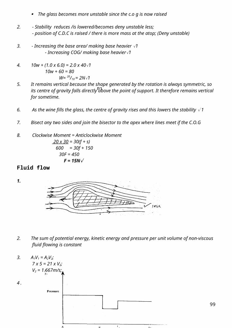
3.0V
3.5W
Determine: i) The e.m.f of the cell ii) The internal resistance of the cell iii) The resistance of the of the lampc) One reason why the earth pin is longer than the neutral and the live pins is to open the
shutters of the socket, state one other reason why it is longerd) Why are lamps in a house always connected in parallel but not in series?
4. State two other factors, which would affect the resistance of a metal conductor other than the temperature
b) The ammeter in the circuit below has negligible internal resistance. The cell has internal resistance of 0.5W and an electromotive force of 3.0V
Determine the value of current the ammeter registers when switch S is closed5. a) State Ohms law 6. In the configuration of resistors given below, determine the current through the 5W resistor
7. Figure 5 is a circuit diagram of three resistors connected to a 6V battery
Determine the potential difference across the 3W resistor8. (a) Study the circuit diagram shown below.
99
V A
X
Figure 5
Figure 7

(i) Determine the reading of the voltmeter V.(ii) Determine the reading of the ammeter A. (iii) Explain the effect on the reading of the voltmeter if the 3W resistor is altered to be 6W
(b) A transformer is designated to work from a 240V a.c. mains and to give a supply of 8V to ring house bells. The primary has 4800 turns.
(i) What type of transformer is this? Give a reason. (ii) Why is the iron core laminated?(iii) Calculate the secondary turns if the efficiency is 100%.
9. The diagram in the figure below shows a wheat stone bridge
K, L, M and N are four resistors joined as shown. The value of resistance of resistor K is unknown. I1, I2, I3 and I4 are the amount of current passing through K, M, L and N respectively. It is also provided that L is a variable resistor. (i) Explain how the set-up is used to determine the value of unknown resistance of K
(ii) State why wheat stone bridge is more accurate in measuring resistance than the voltmeter- ammeter method (b) In an experiment to determine the resistance of a nichrome wire using the metre bridge, the balance point was found to be at 38cm mark. If the value of the resistance in the right hand gap needed to balance the bridge was 25W, Calculate the value of resistance of nichrome wire 10. Four capacitors of capacitance, 3µf, 4µf, 5µf and 3µf are arranged as shown below. Find the
11. In the circuit diagram below, X is a fixed resistor while Y can be varied between O and 100W using a sliding jockey
100
Calculate: (i) The minimum possible current in the circuit (2mks) (ii) The maximum possible current in the circuit (2mks) (c) The following figure shows an electric circuit in which five resistors are connected
to a battery of e.m.f 4.0V and negligible internal resistance
Determine: (i) The total resistance of the circuit (ii) The potential difference between Y and Q (d) Explain two factors that affect the resistance of a metallic conductor
12. Three identical cells of e.m.f. 2.Ov and of negligible internal resistance are connected as shown in figure below. Determine the ammeter reading.
Refraction of light1. The refractive index of paraffin is 1.47 and that of glass is 1.55. Determine the critical angle of a ray of light travelling from glass to paraffin2. The diagram figure 1 below shows a ray of light incident on glass air boundary:
fig. 1
101
5.5W

A second ray strikes the boundary at the same point C at an angle of incident greater than ao. (i) On the diagram, draw the second ray before and after striking the boundary3. a) State Snell’s law
b) When does total internal reflection occur?c) The figure below represents a ray of light falling normally on the curved surface of a
semi- circular glass block A at an angle of 32° at O and emerging into air at an angle of 48°
Calculate the absolute refractive index of the glass of which the block is made. (Assume air is a vacuum)
4. Figure 2 below shows a ray of light traveling from glass to water
Calculate the angle q if the refractive index of glass and water are 3/2 and 4/3 respectively (3mks)5. Figure 3 shows light rays moving from medium 1 to medium 2. If the refractive index of medium 1 is 4/3 and that of medium 2 is 3/2. Calculate angle r
102
qfigure 2
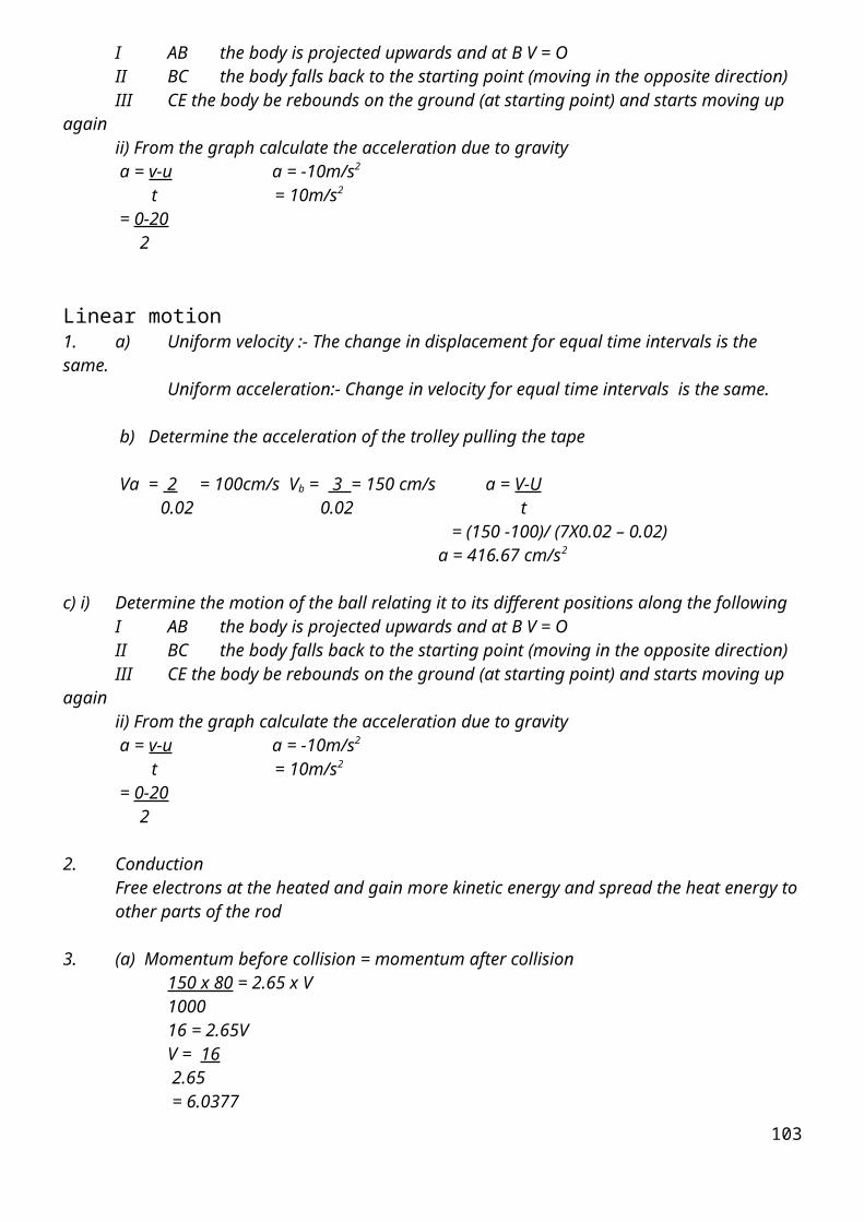
6. (a) The diagram below shows a glass prism and an incident ray striking the face marked AB. The critical angle of the glass is 42o. Use it to answer the questions that follow:-
(i) Complete the diagram showing the path of the emergent ray (ii) Calculate the angle of refraction of the resultant emergent ray7. (a) (i) What is a critical angle as used in refraction of light? (ii) State one condition under which total internal reflection occurs (b) Calculate the value of the critical angle c in the figure below
(c) (i) Show that m = v + 1 f where m = linear magnification , V= Image distance and f is the focal length of lens
(ii) In the table below shows readings obtained out of an experiment to determine focal length of a converging lens
Plot a graph of 1 against 1 and determine the focal length of the lens from the graph. V u (Use the graph paper provided). 8. a) The Fig.9 shows a ray of sunlight incident to face AB of a glass prism. -•
Fig. 9
103
Image distance V (cm) 17.1 18.3 20 23 30Object distance (u) 40 35 30 25 20
i) Complete the diagram showing the observation on the screen. ii) Explain the observation on the screen. iii) State why the spectrum formed above is not pure. b) i) You are provided with four equilateral prisms and four convex lenses. Sketch a diagram showing how all the eight can be arranged to make a simple prism binoculars. ii) State one reason why prisms produce better optical instruments than plane mirrors.
Sound II1. The human ear can distinguish two sounds as separate only if they need it at least 0.1 seconds
apart. How far from a wall must an observer be in order to hear an echo when he shouts.(Speed of sound = 330m/s)
2. A girl standing 220m from the foot of a high wall claps her hands and the echo reaches her 1.29 seconds later. Calculate the velocity of sound in air using this observation
3. A boy standing in front of a cliff blows a whistle and hears the echo after 0.5 seconds. He then moves 17m further away form the cliff and blows the whistle again. He now hears the echo after 0.6seconds. Determine the speed of the sound
4. Sound tends to travel over longer distance at night. Explain
5. You are given two tubes T1 and T2, a clock and a hard wall. Explain how you can use the apparatus to demonstrate reflection of sound
6. State two conditions necessary for total internal reflection to occur
7. A student carrying out an experiment discovered that it took 2 seconds for sound wave traveling through a telephone line to cover a distance d metres and 20 seconds for the same sound traveling through air to cover a similar distance. Determine the ratio of the speed of sound in air to that in the wire.
8. State one factor that affects the velocity of sound in air
104
tube 2
Thin lenses1. The figure below shows how rays from a distant and near objects are focused inside a human eye with a certain defect
Name the defect and state two causes of the defect2. (a) The figure below shows an object O placed in front of an objective lens Lo whose focal length fo is less than fe, the focal length of the eyepiece Le. Complete using ray construction how the arrangement would produce a compound microscope
(b) A nail is placed 25cm from the objective lens of focal length 15cm. On the other side of the objective lens another converging lens of focal length 30cm is placed as the eyepiece. The distance between the two lenses is 52.5cm
Find: (i) the position of the first image (ii) the position of the final image from the eye piece lens
3. (a) The figure below shows a set-up consisting of a mounted lens, L1, a screen S, a metre rule and a candle
(i) Describe how the set-up can be used to determine the focal length, f of the lens. (ii) Explain why the set-up would not work if the lens was replaced with a diverging lens (b) The graph in the diagram in figure below shows the relationship between and for a converging lens where u and V are the object and image distances respectively. From the graph, determine the focal length f of the lens
105
1v
1u
(5mks)
(c) An object placed 15cm from a convex lens forms an image twice the size of the object. Determine the focal length of the lens
106

4. The graph below represents a graph of stopping potential Vs , V against frequency f, Hz
(a) Use the graph to determine: (i) The threshold frequency of the metal (ii) Plank’s constant (iii) Work function of the metal
107
Stop-ping po-tential, Vs
(V)
1.0 X0.8
X0.6X0.4
X0.2
0X10147654321
Frequency, F(Hz)
(b) Figure 8 below shows a mercury vapour lamp, which emits ultraviolet light held over a negatively charged electroscope:
(i) What happens to the leaf after the lamp is switched on? (ii) Explain why it happens (iii) If the experiment is repeated with equally bright red light held the same distance from the plate in place of the mercury vapour lamp, what effect would this have on the leaf?
Give a reason (iv) What does photoelectric effect suggest about the nature of light?
5. (a) Describe briefly a simple method of estimating the focal length of a convex lens. (b) Define linear magnification of a lens. (c) In an experiment to determine the focal length of a converging lens, the following reading were obtained
Image distance V cm 14.3 16.0 17.7 21.0 31.0Magnification m 0.4 0.60 0.80 1.10 2.10
(i) Plot a graph of m against V.(ii) From the graph determine the focal length of the lens.
(d) Which eye defect is corrected by a diverging lens? Show using a diagram how this is achieved
6. a) Describe with the aid of a labeled diagram an experiment to determine the focal length of the lens when provided with the following;
An illuminated object screen A convex lens A lens holder A plane mirror A meter rule
b) A small vertical object is placed 28cm in front of a convex lens of focal length 12cm. In the space below, draw a ray diagram to locate the image and find its magnification. (use a scale: 1cm represents 4cm)c) The figure below shows a human eye with a certain defect
i) Name the defectii) On the same diagram, sketch the appropriate lens to correct the defect and sketch rays
108
figure 8
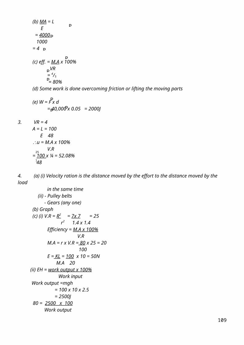
to show the effect of the lens
7. An object of height 10cm is placed in front of a diverging lens of focal length 25 cm and at a distance of 20 cm from the lens. Calculate the height of the image formed
8. (a) The figure below shows an object, O, placed in front of an objective lens Lo whose focal length, ƒo is less than the focal length of the eye piece lens; Le Complete using ray construction how the arrangement would produce a compound. Microscope
(b) A thin converging lens of focal length 30cm is used to form a real image on a screen 90cm from the lens, Determine :- (i) The object distance (ii) The magnification
9. Figure 2 shows an object O placed in front of a concave ion with principal foci F and F1. Construct a ray diagram to locate the position of the image
Fig 2
10. Use a ray diagram to show how short sightedness in a human eye can be corrected.
11. a) An object is placed 15 centimeters in front of a diverging lens of focal length 20 cm. Use a ray diagram to determine the image distance and its magnification. b) A nuclide F has a half life of 5 hours. What percentage of the original number of atoms of the isotope would have decayed after 30 hours?
c) A current of 1.5A flows through a conductor in 5 seconds. Determine the number of electrons that pass through the conductor (charge on an electron = 1.6 x 10⁻¹⁹ C) 12. Calculate the wavelength of the KBC f.m radio waves transmitted at a frequency of 95.6 mega Hertz
109
F1

Quality of heat1. 500g of a metal is heated to 100oC and then placed in a 200g mass of water at 15oC. If the final temperature rises to 21oC, calculate the specific heat capacity of the metal. (Specific heat capacity of water = 4200J-1kg-1
Waves II1. (a) (i) Distinguish between stationary and progressive waves (ii) State a reason why a closed tube or pipe produces less quality sound than an open one (b) The figure below shows a piston inside a glass tube
Air inside is made to vibrate producing a fundamental note. Find the fundamental frequency to be produced
(c) If the glass tube is made open by removing the piston and opening the other end, what is the new fundamental frequency?
2. The figure below shows circular waves approaching a straight reflector. Complete the sketch to show what happens when the waves hit the reflector.
3. (a) State one difference between the way sound waves and electromagnetic waves are transmitted. (I) A mine worker stands between two vertical cliffs 400 m from the nearest cliff. The cliffs are X distance apart. Every time he strikes the rock once he hears two echoes, the first one comes after 2.5 sec. while the 2nd follows 2sec. later. From this information; Calculate; (i) Speed of sound in air. (ii) The value of X.(b) The figure below shows waves starting from two coherent sources S1 and S2.
110
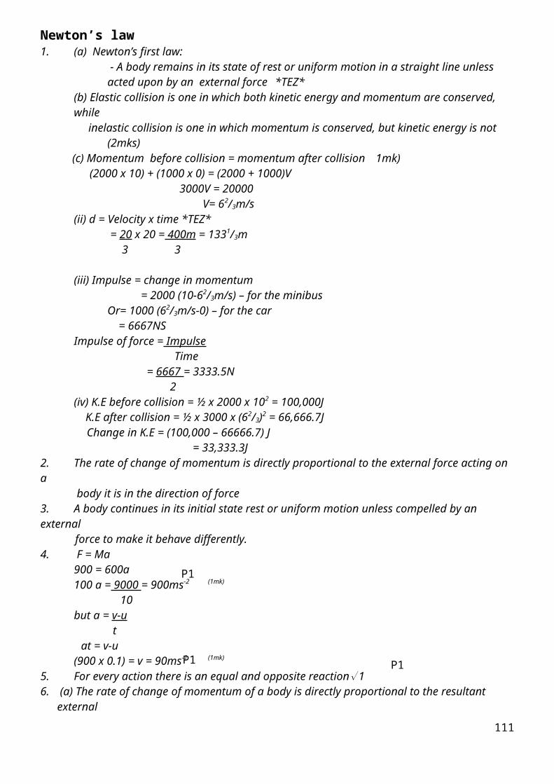
Displacement (m) Displacement
(m)8m
What would be observed at P if the waves are (i) light waves. (ii) Sound waves.(c) State the conditions for diffraction of light to occur.p1 mk
4. The diagram below represents plane wave fronts produced in a ripple tank.
Given that the distance AB is 15 cm, determine the wavelength of the wave 5. (a) The figure below shows a wave profile with velocity 340m/s
Determine: (i) The frequency of the wave (ii) The period of the wave
(b) On the same diagram in (b) above sketch a wave profile of another wave with same frequency, greater amplitude but 180o out of phase with the one in (b)
6. Figure 3 shows the displacement of a particle in a progressive wire incident on a boundary between deep and shallow region
111

Complete the diagram to show what is observed after bounding. (Assume no loss of energy)7. (a) Explain the difference between progressive waves and stationary waves (b) State any two conditions necessary for the establishment of a stationary wave (c) (i) The figure below shows two loudspeakers L1 and L2 connected to a signal generator
An observer walks along the line 0-01 (equidistant from L1 and L2) and another along the Line AA1.Explain the observation made by each and give reasons to your answer (d) If a wave is propagated at a velocity of 50m/s; determine its frequency if the distance travelled by the wavelength in 2 cycles is 1.25m (e) State one condition necessary for interference to occur
8. Give conditions necessary for diffraction of waves to occur9. Distinguish between diffraction and refraction of waves10.
Determine the frequency of the wave11. The figure below shows a wave profile.
Determine the frequency of the wave.
12. The following shows a diagram of displacement against time cure of a standing wave reflected its own pith
112
2.0m
12.0m 16.0mTime (x10-2)s
- 2.0m
P1
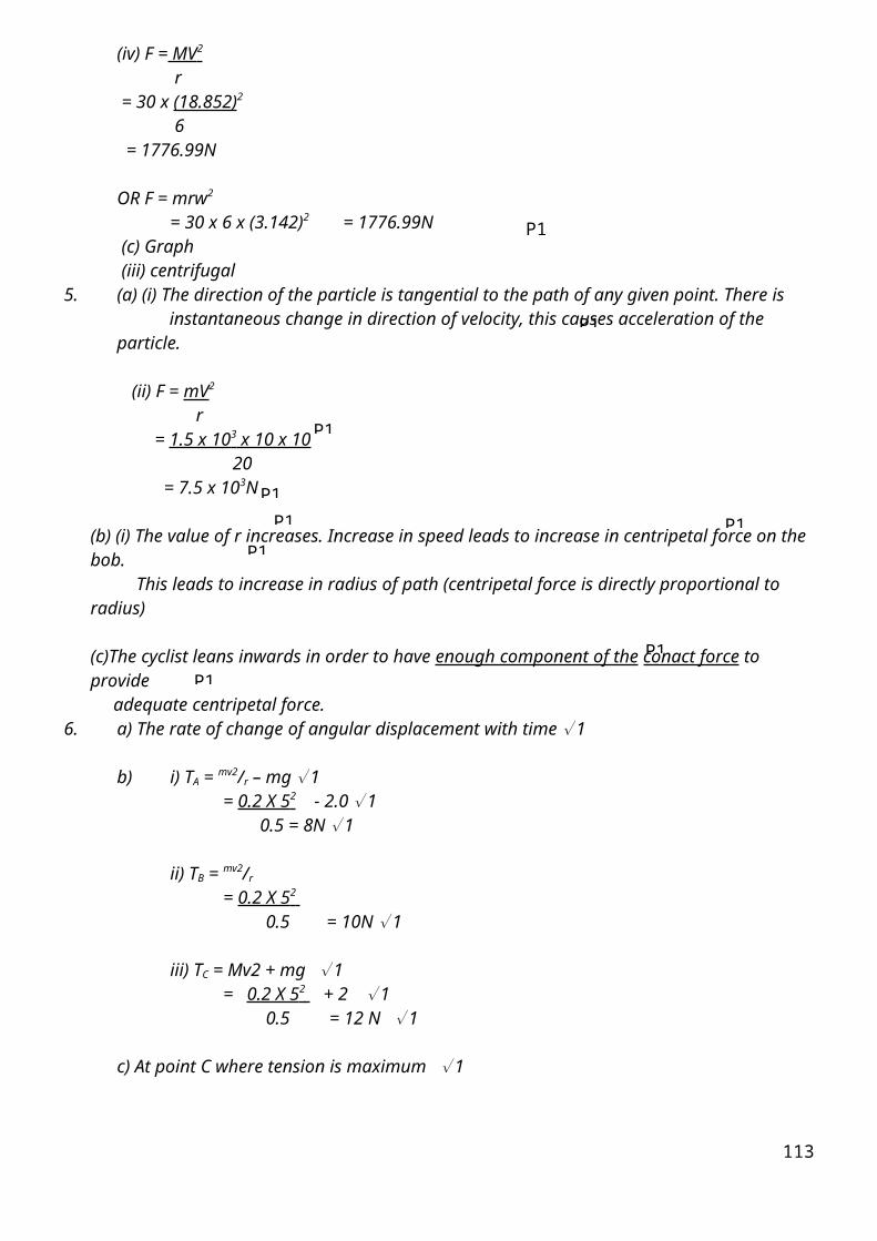
Determine the period of the wave (3mks)
13. A student touches the surface of water in a big pan at point A at regular intervals and observes the ripples as in the diagram below. Explain the pattern of the ripples observed.
14. In the figure below shows a series of plane wires approaching a gap. Complete the diagram to show the wire after passing through the gap if
15. (a) (i) State the difference between mechanical and electromagnetic waves (ii) Give one example of each of the above waves (b) The figure below shows water waves crossing a boundary between deep and shallow water
Complete the diagram to show the wave in the deep region(c) (i) Complete the diagram below to show the shape of the wave fronts after passing through the deep gap
(ii) What is the relationship between periodic time and frequency of a progressive wave?(iii) Explain why radio waves reception is better than T.V reception in mountainous regions
113

16. a) i) Distinguish between stationery waves and progressive waves. In terms of their propagation. ii) State a reason why a closed pipe produces less quality sound than an open pipe. b) The Fig. 10 represents an oscillation taking place at a particular point while a sound wave in a gas passes the point. The vertical axis is labeled displacement.
Fig. 10
i) Explain what is meant by displacement in this context. ii) From the figure determine: I. The period.
II. The frequency
c) Calculate the wavelength of the sound wave in the figure. Take the velocity of sound in the gas to be 34m/s d) State two factors that can. increase the speed of sound in. solids
Work, energy and power1. Given that a lamp is rated 45W 240V. Calculate the resistance of the heating element. 2. An electric bulb is rated 40W, 240V. What is the resistance of its filament?3. An electrical immersion heater is rated 3kW, 250V. Choose a suitable fuse from 3A, 5A, 10A,
12A, and 20A that can be used in such an appliance.4. An electric kettle is rated 3KW, 250V. Determine the resistance of the coil5. An electric kettle rated 3.0Kw, 240V is filled with water. If the water boiled after 8 minutes of heating, determine the energy used in boiling the water.6. (a) An electrical heater is rated 3.45KW. The heater is immersed in 2.4kg of water. Calculate the minimum time it takes for the temperature of the water to rise from 23.0oC to 69.0oC. (Specific heat capacity of water = 4.2Jg-1K-1)
Floating and sinking1. Define thermionic emission2. (a) State:- (i) Archimedes’s principle (ii) The law of floatation
(b) The solid of mass 12kg, weighs 100N and 94N when fully immersed in water and liquid L respectively. Calculate:-
(i) The density of the liquid in S.I units (ii) The density of the solid
114
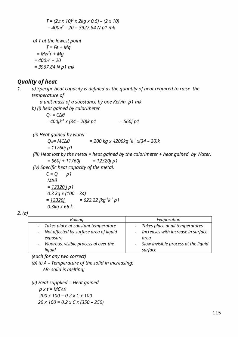
Photoelectric effect1. (a) Define the following: (i) Photoelectric effect (ii) threshold wavelength (b) The variation of frequency f with the maximum kinetic energy Ek of the emitted electrons is shown on the graph below:
Using the graph above, determine (i) the threshold frequency fo of the radiation *RCH*
(ii) the value of the Planck’s constant h (iii) the work function, Wo
(c) On the same graph in (b) above, draw a line to show the variation of frequency, f, with the maximum kinetic energy, Ek, of the emitted electrons from a second metal which has a lower work function that used in (b)2. Figure 8 below shows a mercury vapour lamp, which emits ultraviolet light held over a negatively charged electroscope:
(i) What happens to the leaf after the lamp is switched on? (ii) Explain why it happens (iii) If the experiment is repeated with equally bright red light held the same distance from the plate in place of the mercury vapour lamp, what effect would this have on the leaf?
Give a reason 115
figure 8
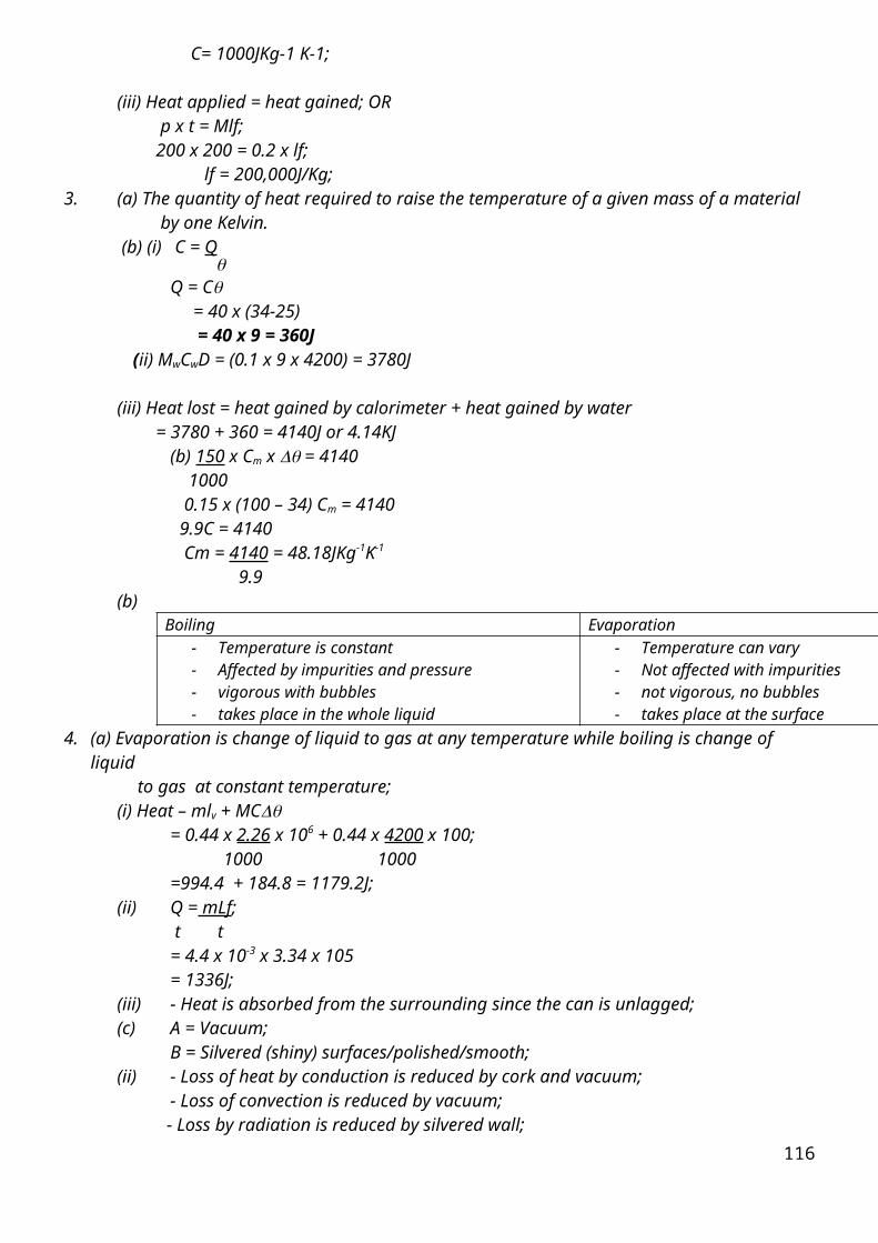
(iv) What does photoelectric effect suggest about the nature of light?3. Calculate the wavelength of Green light whose energy is 3.37 x 10⁻¹⁹ J .
(h = 6.63 x 10⁻³⁴JS, C = 3.0 x 10⁸m/s)4. a) Define the term work function
b) Name one factor that determines the velocity of photoelectrons produced on a metal surface when light shine on it
c) In a photoelectric effect experiment, a certain surface was illuminated with radiations of different wavelengths and stopping potential determined for each wavelength. The table below shows the results obtained.
Stopping potential , Vs 1.35 1.15 0.93 0.62 0.36Wave length, (x10-7m) 3.77 4.04 4.36 4.92 5.46
i) On the grid provided plot a graph of stopping potential (Y –axis) against frequencyii) From your graph determine:
a) The threshold frequencyb) The plank’s constant, h
(e = 1.6 x 10⁻¹⁹ Coulomb, C = 3.0 x 10⁸ m/s)5. a) State the role of the Grid in a cathode ray tube b) Explain why a magnetic field is used in the TV deflection system instead of an electric field
c) The time base of a CRO is 25ms/div while its gain is 2.5V/div. Use this information to answer the questions that follow:
i) Calculate the frequency of the signalii) What is the peak voltage of the signal
6. The graph below shows the relation between the stopping potential, Vs and the frequency of radiation when a certain surface is illuminated with light of different frequencies
From the graph determine:- (i) The threshold frequency (ii) The value of plank’s constant (e = 1.6 x 10⁻¹⁹C) (III) The work function of the material
116

7 a) State one reason why a C.R.O is a more accurate voltmeter than a moving coil voltmeter (b)The diagram below represents a cathode ray oscilloscope (CRO)
;
i) Name the parts labeled A and Bii) What are the functions of C and D?iii) State how electrons are produced
8. a) What is meant by the term photo electric effectb) In an experiment using a photo cell, ultra violet light of varying frequency strikes a metal
surface. The maximum Kinetic energy (KE max) of the frequency F is measured. The graph below shows how the maximum kinetic energy varies with frequency F
Use the graph to determine:-i) Threshold frequency Fii) The plank’s constant, hiii) Work function of the metal
117
K.E max ( X 10-19kJ)
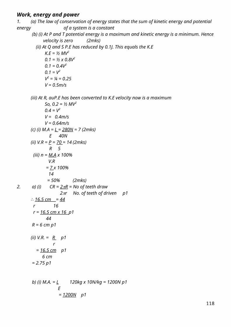
9. (a) The diagram fig 9 below shows a photo cell; connected in a circuit:-fig. 9
(i) Complete the diagram by indicating the correct polarities in the gap for current to flow in the circuit (ii) State and explain the effect of using light of different wave lengths on the amount of current flowing in the circuit given that the distance of the source of light remains the same (b) Two fixed resistors one of 100W and the other of unknown resistance are connected in parallel. The combination is placed in a circuit and current passing through the combination was
measured for various p.d. The graph in figure 10 below drawn to scale shows the results:-
(i) From the graph, calculate the total resistance of the combination
(ii) Determine the value of the unknown resistance
(c) (i) Explain the cause of eddy currents and how they are minimized in a transformer
(ii) A transformer with 4200 turns in the primary coil operates a 240V mains supply and gives an output of 8.0V. Determine the number of turns in the secondary coil (assuming it is 10% efficient)
118
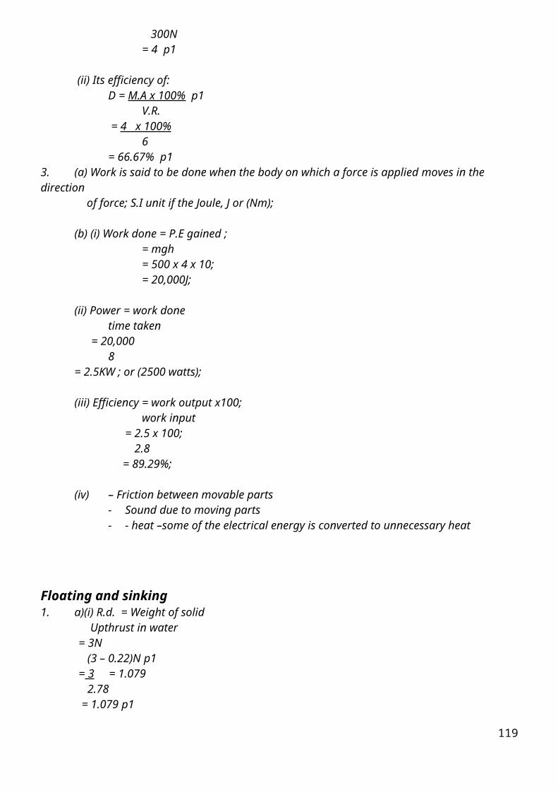
10. State one factor that affects photoelectric effect11. a) i) What is photoelectric effect?
ii) You are provided with the following; a photo cell; a source of UV light, a rheostat, a source of e.m.f, a millimeter, a voltmeter and connecting wires. Draw a circuit diagram to show how photoelectric effect may be demonstrated in the laboratory b) In a photoelectric effect experiment, a certain surface was illuminated with radiation of different frequencies and stopping potential determined for each frequency. The following results were obtained:
i) Plot a graph of stopping potential (Y-axis) against frequency ii) Determine plank’s constant, h and the work function of the surface given that EVs = hf – hfo, where hfo = Qe = 1.6 x10⁻¹⁹ C c) A surface whose work function Q = 6.4 x 10⁻¹⁹ J is illuminated with light of frequency 3.0 x10¹⁵ Hz. Find the minimum K.E of the emitted photo electrons (use value of h obtained in b(ii) above)
ELECTRICITY & Electronics1. State one advantage of a lead-acid accumulator over a dry cell2. State one defect of a simple cell and explain how it can be corrected.3. Study the circuit below:
Determine the current flowing in the circuit4. When the time base of a cathode ray oscilloscope is turned on, there is a horizontal trace across the screen as shown in the figure:-
(i) An alternating potential difference of constant frequency and constant amplitude is then connected to the Y-input of the oscilloscope. Sketch on the same diagram above the trace which might be obtained (ii) The time base is switched off but the alternating potential difference is left connected. Describe what would be observed on the screen5. The figure below shows the wiring in a modern mains appliance
119
P
Frequency (f) (x 1014 Hz) 7.95 7.41 6.88 6.10 5.49Stopping potential, (Vs), (V) 1.35 1.15 0.93 0.62 0.36

Identify the wires Y and Z 6. State two ways of decreasing capacitance7. (a) The figure below represents part of an electric cooker coil.
(i) State why the part labeled W is coiled (ii) State the property of material X that makes it suitable for its use (b) State the advantage of transmitting power at:- (i) Very high voltage (ii) Alternating voltage (c) Aluminium wires are commonly used in power transmission than copper wires. Give two advantages of aluminum as transmission lines
(d) The diagram below shows a wrongly wired three pin plug.
(i) Indicate in the diagram above the correct colors for the wiring (ii) State the use of device marked X
(e) A household uses a 1.5Kw water heater for 2 hours a day for 30 days. If the cost of electricity is shs.6.70 per Kwh, how much will they pay for this consumption?
8. The diagram below shows a simple cell:-
(a) (i) Name z and solution y (ii) Name and explain the defect that occurs at plate z (iii) Give one method of preventing the defect that occurs at the copper plate
(b) (i) Explain how P-type semi-conductor is formed (ii) The figure below shows a circuit diagram for full wave rectification
120
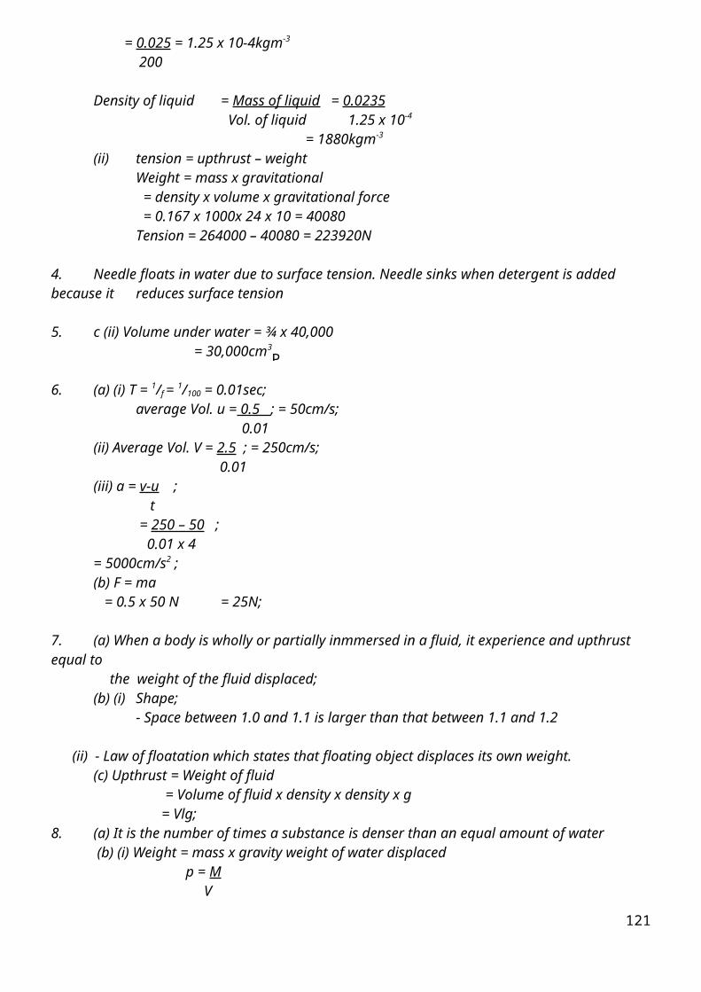
(I) Draw the diodes D3 and D4 on the diagram to complete the circuit (II) On the axes below sketch a voltage –time graph observed when a C.R.O is connected at points
(a)PQ (b) ST
(iii) On the circuit diagram (b) (ii) above, draw a capacitor which can be used to smoothen the output voltage9. Explain how conductivity of a semi conductor changes with increase in temperature10. With the time base switched on; the following trace was obtained on the screen of a CRO as shown in the figure below:
Draw a circuit diagram that can be used to produce the wave above11. Figure 4 below shows a circle with two diodes P and Q and a cell:-
Explain the observation which would be made if S is closed12. Explain why eight 1.5V cells arranged in series to give a total of 12V cannot be used to start a car. But car battery of 12V starts a car
13. a) i) Distinguish between a p- type and an n- type extrinsic semi conductors ii) The figure below shows a bridge rectifier
121
Figure 4

A capacitor has been connected across the resistors as shown. Sketch on the axes below the wave form when a C-R-O is connected across the resistor; R
Sketch on the same axes above the wave form when a C-R-O is connected across the resistor R and capacitor c removed
iii) Figure shows a voltmeter connected across the cell. The voltmeter reads 1.5V when the switch S, is open and 1.25V when the switch is closed.
i) What is the e.m.f of the cell?ii) What is the terminal voltage of the cell?iii) Calculate the internal resistance of the cell
14. What is the use of a fuse in an electric circuit?15. Distinguish between Topping and Dopping16. The figure below shows the set up for a simple cell.
a) Name the Electrode A and the solution B b) State two reasons why the bulb goes off after a short time 17. The figure 2 shows a simple cell made of copper and zinc electrodes dipped in dilute
sulphuric acid
122
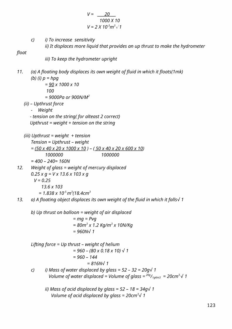
a) Identify the cathodeb) If a voltmeter is connected across the rods the reading is observed to reduce with time.
State two causes of this observation18. State one reason why colour televisions have a higher power rating than black and white televi-
sions19. Explain two factors that affect the capacitance of a parallel-plate capacitor20. a) A girl opened up a used up dry cell and found the following:
i) The zinc casing was ‘eaten away’ ii) The cell was watery Name the cell defectb) Three identical bulbs are connected in series with a battery of dry cells. At first the bulbs
shine brightly but gradually become dimmer. Using the same cells, explain how you would increase the brilliance of the bulbs 21. Figure 9 below shows a diagram of an n – p – n transistor.
(a) Complete the diagram by showing the connections of two batteries suitable for biasing the transistor in the common- emitter mode.
Figure 9
22. State the purpose of introducing an impurity in a semi conductor.23. In an attempt to establish the relationship between current through a junction diode and the p.d across it, a student connected a diode to an e.m.f source as in figure 3 below:-
fig. 3
(a) State whether the diode is forward biased or reverse biased(b) Briefly describe how she obtained her readings
(c) Sketch a graph to represent the relationship between current (y-axis) and the p.d across the diode
123

24. Figure 8 shows a circuit where a battery of emf 4.5V, switches A and B, two capacitors . C1= 0.3 µF and C2 = 0.5 µF and a voltmeter are connected
a) Determine the charge on C1 when switch A is closed and switch B is openb) What is the effective capacitance CT when both switches A and B are closed?
c) State what is observed on the voltmeter when;i) Switch A is closed and switch B is openii) Switch A is closed and opened and then B is closediii) Explain the observation made in c(ii) above
25. (a) Define capacitance (b) Two aluminium plates A and B of same dimensions are each mounted on an insulating stand. Plate A is charged to high voltage and connected to uncharged electroscope while plate B is earthed. The two plates are placed side by side as in the diagram figure 4 below:-
fig . 4
(i) Indicate on the diagram the position of the leaf and charge distribution on the electroscope (ii) State and explain the observation on the electroscope when the distance (x) of separation between the plates is increased while keeping the area of overlap the same (c) A 12mf capacitor is charged with a 200V source then placed in parallel with uncharged 8.0mf capacitor as shown in fig 5 below:-
fig. 5
Determine: (i) The initial charge on the 12mf capacitor (ii) The final charge on each capacitor
124
12mf 8mf
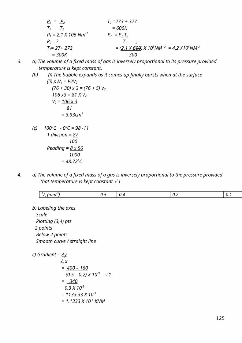
(d) The diagram figure 6 below shows a pear shaped charged conductor on an insulating stand (charges not shown on the diagram)
fig. 6
Part A is touched using a proof-plane and then the proof-plane is brought next but not touching the cap of a leaf electroscope (not shown on the diagram). The same experiment is repeated for part C of the conductor. (i) State the expected observation in the above experiments (ii) Explain the observations made in (d) (i) above (iii) Name any one application of the above phenomenon
26. a) State two factors that affect the capacitance of a parallel plate capacitorb) The diagram below shows an arrangement of capacitors in a circuit
i) Determine the total charge in the circuit
27. a) What is doping as used in electronicsb) Distinguish between intrinsic and extrinsic semi-conductors.c) What would be observed in the diagram below when switch S is closed, B1 and B2 are
identical torch bulbs
125

28. a) Define Eddy currentsb) The diagram below shows the north pole of a magnet approaching a solenoid
i) Using Lenz’s law, indicate the direction of current through the galvanometer ii) Explain the observation made when:
I The magnet is moved away from the solenoidII The magnet is placed stationary in the solenoid
c) A transformer is designed as shown in the figure below. If the primary coil has 2400 turns and the secondary has 200 turns calculate the p.d across BC assuming there are no energy losses in the transformer
d) The figure shows a cross- section of a bicycle dynamo. The wheel is connected by an axle to a permanent cylindrical magnet and is rotated by the bicycle tyre
i) Explain why the bulb lightsii) How can the bulb be made brighter
29. A car battery requires topping up with distilled water occasionally. Explain why this is necessary and why distilled water is used30. Draw appropriate symbol of a circuit diagram of a junction diode in reverse bias
126

31. a) In the circuit diagram shown in Fig.5 each cell has an e.m.f of 1,5v and internal resistance of 0.5Ω. The capacitance of each capacitor is 1.4mF.
Fig.5
i) When the switch S is closed determine the ammeter reading. ii) When the switch S is closed determine the charge on each capacitor. b) The diagram in Fig. 6 represents two parallel plates of a capacitor separated by a distance d. Each plate has an area of a square unit. Suggest two adjustments that can be made so as to
increase the effective capacitance.Fig.6
c) Complete the table to describe the function of the parts of a lighting conductor. Port FunctionSpikeThick copper rodEarthed metal plate
32. The circuits in Fig. 7 shown are close to each other.
Fig. 7
a) When the switch is closed, the galvanometer shows a reading and then returns to zero. When the switch is then opened, the galvanometer shows a reading in the opposite direction and then returns to zero. Explain these observations.
b) Energy losses in a transformer are reduced by having a laminated soft iron core. State and explain two other ways of reducing energy loses in a transformer.
127
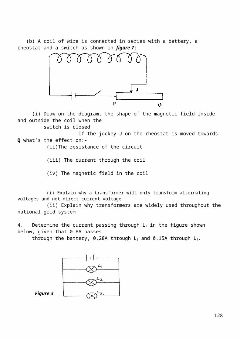
c) The e.m.f generated as the soil of an alternating generator rotates is represented in the graph in Fig. 8.
i) Give reasons for the changes in the e.m.f as the coil rotates from 00 to 900 and 900 to1800. ii) Sketch on the same diagram a similar graph if the generator was a direct current one.
33. State one advantage of: i) A lead-acid accumulative over a dry cell ii) A dry cell over lead-acid accumulator
34. Three identical cells of e.m.f. 2.0v and of negligible internal resistance are connected as shown in figure below. Determine the ammeter reading.
35. State one advantage of: i) A lead-acid accumulative over a dry cell ii) A dry cell over lead-acid accumulator 36. Compare the property of material used to make a fuse wire to one used to make the filament of a torch bulb.37. State two reasons why the CRO is a more accurate voltmeter than a moving coil voltmeter. 38. The strip below represents part of the electromagnetic spectrum. C is the visible part of the
spectrum. A is the region of the shortest wave length and F the highest
Name the sections which represent:
(i) X-rays (ii) Infra-red (iii) T.V waves 39. Sketch a forward bias characteristics of a P – N junction diode in the axis below
128

X-ray1. Give one use of X –rays in medicine 2. State the factor that affects:- (i) The intensity of X-rays (ii) The strength of X-rays3. An x-ray tube must be highly evaluated. Give a reason for this4. a) In the production of X- rays, electrons are directed at a tungsten target. State a reason why the target is made of tungsten
b) How can the intensity of the X-rays tube be increased?5 a) Arrange the following waves in order of increasing frequencies: microwaves, x-rays, Infra-red, ultra-violet b) The table below shows the electromagnetic spectrum;
B
i) Identify A and B ii) State one use for each
6. Figure 12 below shows an x-ray tube:
(a) Indicate on the diagram the path of x-ray beam supplied by the tube (b) Why is M set at angle of 45o relative to the electron beam? (c) Name a suitable metal that can be used for part M and give a reason for your choice (d) State how the following can be controlled:- (i) Intensity (ii) Penetrating power
(iii) The exposure to patients (e) An x-ray tube is operating with an anode potential of 12Kv and a current of 10.0m.A: (i) Calculate the number of electrons hitting the anode per second (ii) Determine the velocity with which the electrons strike the target (iii) State one industrial use of x-rays7. (i) The diagram below shows simplified diagram of an x-ray tube,
(a) Name the parts A, B, and C.(b) What adjustments would be made to:
129
figure 12
•
Figure 8
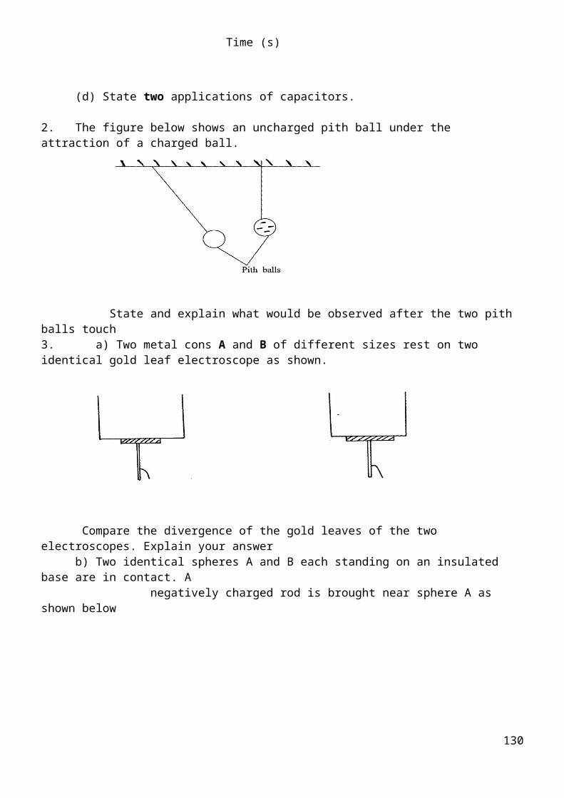
EHT
Evacuated tube
(i) Increase the penetrating power of the x-rays produced. (ii) Increase the intensity of the rays produced. (c) Name a suitable material for the part marked B and give a reason for your choice. (d) Name a suitable material for the part marked C and sate its purpose.
(e) Why is it necessary to maintain a vacuum inside the tube? (f) State one use of x-rays in the following areas; -
(i) In medicine (ii) In Industry.
8. a) The figure shows the circuit of a modern X-ray tube
i) Indicate the path of the X-ray beam supplied by the tubeii) Name the part labeled C and state its function (2 mks)iii) If the tube above is operated at an accelerating potential of 100kV and only 0.05% of
the energy of the electrons is converted to X – rays, calculate the wave length of the generated X-rays. (Take electric charge e = 1.602 x10⁻¹⁹C, planks constant h = 6.63 x 10⁻³⁴ Js, and speed of light c = 3.0 x 10⁸m/s)
iv) State two properties of X-raysv) State one industrial application of X-rays
9. Below is a nuclear reaction
A B C i) Identify radiation K
ii) Determine the value of X and Y
10. a) State the energy changes that take place in an X - ray tube b) Electrons in an X-ray tube are accelerated by a potential difference of 40 kV. If 20%
of the electrons are converted into X- rays, determine the maximum wavelength of the emitted electrons. c) i) Draw a simple circuit consisting of a photocell to show the direction of flow of current ii) The diagram below shows a wave form displayed on a CR0 screen.
130
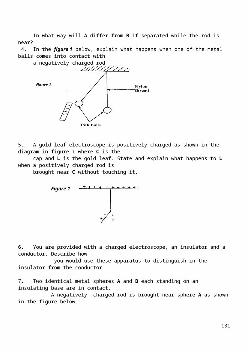
If the Y — gain reads 0.5V cm-1 while the time base is set at 0.1 ms cm-1, determine the amplitude and frequency of the wave.
11. The table below shows results obtained in an experiment to determine the internal resistance of a cell
V(V) 0.4 0.5 0.6 0.7 08 1.3R(W) 0.45 0.65 0.80 1.05 1.40 2.41/V (V-1)1/R(W-1)
i. Complete the table for values of 1/V and 1/R giving your answers to 3 d.p ii. Plot a graph of 1/V against 1/R
iii. Use the graph to determine the e.m.f E and the internal resistance r of the cell given that E = r 1 V R
Radioactivity1. (a) Define radioactive decay (b) A radioactive element decays to 1/128 of its original activity after 49 days. Determine its half –life2. (a) You are provided with the following:-
- One diode-A load resistor- An a.c. source- One transformer
(i) Using the above apparatus draw a circuit arrangement for half wave rectification (ii) Explain how the circuit drawn in (a)(i) above achieves half wave rectification (b) (i) Determine the value of x and y in the nuclear equation below:-
(ii) The half life of a radioactive element is 20minutes. The mass of the element after 120 minutes is 0.03125g. Determine the original mass of the element (iii) What evidence supports the fact that gamma rays are not charged (iv) Alpha particles have low penetrating power as opposed to beta particles. Give a reason for this v) A manufacturer wishes to check the thickness of steel sheets he produces. Explain how
this can be done using a radioactive source and a counter
3. a) What is meant by radio active decay?b) Uranium 235 was bombarded with a neutron and fission took place in the following manner:
92 U + 1
0n 38Rn + bX + 10( 0n)
Determine the values of a and bc) When carrying out experiments with radio active substance one is instructed that the source
should never held with bare hands but with forceps. Give a reason for the instruction
131
+
a1
90235

d) The diagram below shows the paths taken by three radiations A, B and C from a radio active isotope through an electric field
i) State the charge on plate Y ii) Identify the radiation A and C iii) Give a reason why C deviates move Ae) 90 Th disintergrates into radium (Ra) by emission of two alpha and two beta particles as
in equation 90 Th ZRa + 2(
2H) + 2 ( -1)
State:i) The atomic number of the daughter nuclideii) The mass number of the daughter nuclidef) One of the application of Beta emission (B) is controlling thickness gauge. Explain how they are used for this purpose?
4. The following is a nuclear reaction for a fusion process resulting from the reaction of polonium with loss of beta particles
(i) Determine the values of S and T (ii) State the source of the energy released
5. The expression below is an equation for radioactive element A. Element B and C are the daughter nuclides. A, B and C are not the actual symbols of any of the elements
238 234 X A B + C92 90 Y(a) State what type of radioactive decay this is.(b) What is the value of:
X……………… Y……………………
6. Arrange the following in order of increasing frequency: Red light, Infrared radiation, X-rays, UV radiation, Short –radio waves, TV and Fm radio waves, Am radio waves and Long radio waves.7. Radium -222 is a radioactive element with a half-life period of 38 sec. What fraction of the mass
of a sample of this element remain after 380 sec.8. (a) Define the term half-life of a radioactive material (b) (i) Use the table below to plot a graph of activity against time
Activity (Disintegration/seconds) 680 567 474 395 276 160 112 64Time t (days) 0 1 2 3 5 8 10 14
(ii) Find the half-life of the material in days (c) The half-life of a radio-active substance is 138 days. A sample of the substance has 8 x 10¹⁰ un-decayed nuclei at time t = 0. How many un-decayed nuclei will be left after 690 days?
(d) An element x (uranium) decays by emitting two alpha particles and a beta particle to yield element Y
132
233e4A
P 1

(i) State the atomic number and mass number of Y (ii) Write down the decay equation 9. a) What is meant by radioactive decay? b) A radioactive source placed 12cm from the detector produced a constant count rate of 5 counts per minute. When the source is moved close to 3cm, the count rate varies
as follows;Time 0 20 40 60 80Count rate 101 65 43 29 21
i) State the type of radiation emitted.
ii) Explain the constant count rate when the source is 12cm away. iii) Plot a graph of count rate against time (Use graph paper) iv) Use the graph to estimate the half life of the element10. State one advantage of: i) A lead-acid accumulative over a dry cell ii) A dry cell over lead-acid accumulator
GM induction1. What is Fleming’s right hand rule used for? 2. State Lenze’s law of electromagnetic induction
SECTION II ANSWERSPressure
1. P1 = P2
hxexg = hyiyg
0.06 x 1200 x 10= hy x 900 x 10hy = 120 x 6 9000 = 0.08mh =hy + 3cm = 8cm + 3cm = 11cm
Current II1. 120 = 4t
t = 120 p1 mk 4
= 30 hrs p1 mk
2. I = Q = 40 = 40 = 4A t 600 10 60
3. (a) (i) - When the switch is closed current flows through the coil causing a magnetic field. This repels the magnet towards the chime bar.
- The end of the coil adjacent to the sound pole of the bar magnet acquires a south pole.
(ii) – Increase he number of turns in the coil.- Increase d.c source.- - Introduce a soft iron core in the coil.
133
P 1
P 1
P ½
P ½
P1

(b) (i) Electrical – magnetic - potential – sound energy
(ii) Resistance in the circuit increase. (iii) Current reduces.
(iv) Become less stronger.
(c) (i) - In alternating current there is a change in the magnetic flux of the primary coil linked to the secondary soil.- In direct current there’s no charge in the flux therefore no inducement of e.m.f in it.
(ii). - Transformers step up voltage to higher value for transmission which minimizes power loss.
- They also step down higher voltage to the voltage required by the consumers.4.
(a) Current tough L1: 0.8 = 0.15 + 0.28 + L1
0.8 = 0.43 + L1
L1 = 0.37AThermal expansion1. Water freezes and the ice formed floats in water because its density is less than that of water, in-
sulating water below it. Temperatures increases down the pond because of anomalous expansion of water
134
2mks P ½ P ½ P ½ P ½
P1P1P1
P1
P1 P1
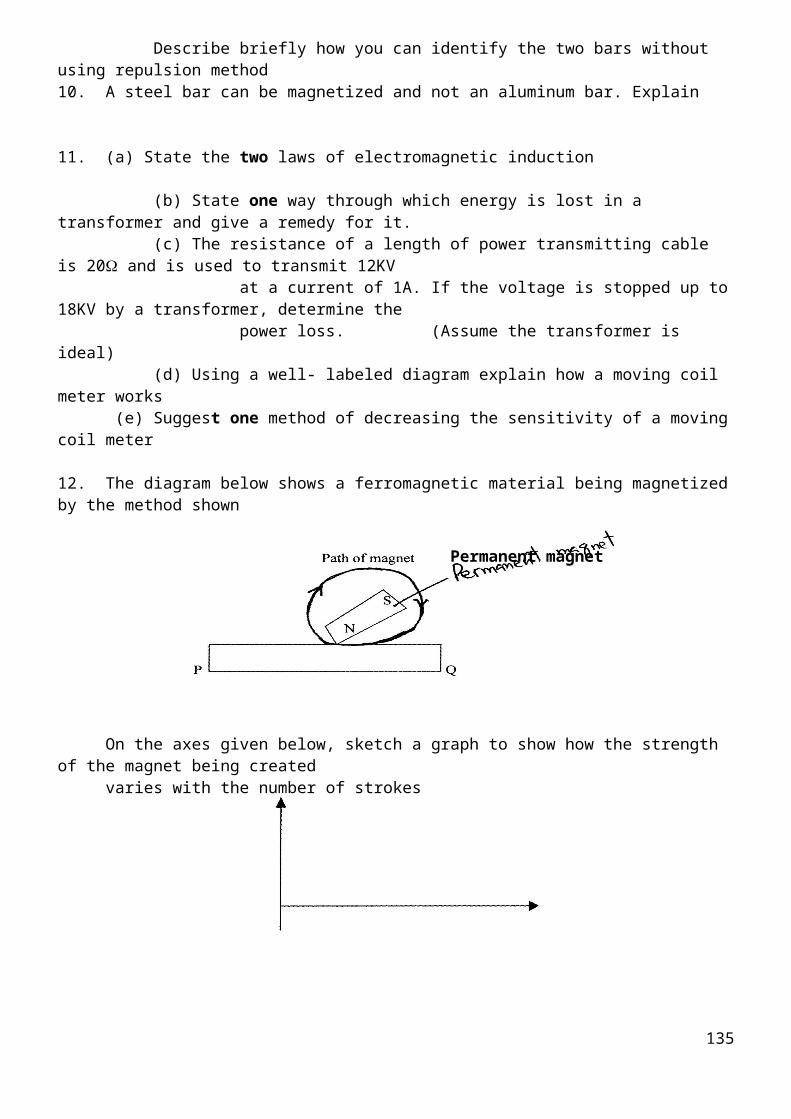
Light.1. 20 = 2.5 Ö
30000 hO
h0 = 30000 x 2.5 20
= 3750cm= 3.75m Ö
Electrostatics1. a) Charges at x get neutralized. p1 mk C is pointed and due to point action p1 mk charges leak off from C and are attracted to x neutralizing it. p1 mk
b) Leaf rises. p1 mk A position charge is induced on the surface of hollow conductor, these repels the charges
from the cap of the electroscope making the leaf to diverge with the charge. p1 mk
c)
d) – Smoothening waves. p1 mk - Reduction of sparks in induction coil p1 mk - In camera flash. p1 mk - delay circuits p1 mk (any two)2. After touching, the pith balls share the charge and become negative hence they repel.3. a) – The divergence of B is greater the divergence of A - B has a smaller surface area than A, has low capacitance than A (Q= CV)
b) - A will have a net positive charge while B will have a net negative charge
4. The two balls will acquire negative charge and repel5. The gold leaf will diverge further because more positive charges will be repelled from the cap to the leaf by the positively charged rod6. Each material is brought in turn to touch the cap. The conductor will discharge the electroscope while the insulator will not (accept bring near conductor gauge)7. A will have a positive charge when charged rod is brought near metal A. positive charges are attracted towards it while the negative charges are repelled
Measurement II
1. Main scale = 6.5mm Thimble scale = 0.34mm Micrometer reading = 6.84mm
Magnetsim135
1mk P
P 1 P ½

1. a i) The free ends repel because they have some polarity, p1 mk
ii) Free ends have different polarity hence attract. p1 mkb i)
ii) magnetic shielding. p1 mk2 All ferromagnetic materials are attracted by magnets or any magnetic material is attracted3. (a) (i) Soft iron - It is easy to magnetize and demagnetize (ii) Least force = mg = 150 x 10 = 1.5N 1000 (iii) – Increase the number of turns of the coil. - Increase the amount f current /p.d
(iv) When all the domains have been aligned i.e point of magnetic saturation, the strength of magnet is maximum and cannot increase beyond this point
(b) Correct coil around A Correct coil around B Complete correct circuit
4. Domains of soft magnetic materials are easy to arrange and disarrange while the domains of hard magnetic materials are hard to arrange and disarrange.
5. The pin or wooden block was attracted while the one on the metal block was not attracted. Magnet induces magnetism on the pin. On the iron block which induces magnetism on the iron block. The pin on the wooden block didn’t induce magnetism to the wooden block.
6. Correct direction of field
7. The two pith balls separate Charges (-ve) are transferred from the uncharged pith ball but are not enough to neutralize
the charged one. The initially uncharged pith ball now becomes positively charged hence the separation/repulsion.8. (a) A – North pole B – North pole (b) R is stronger. It repels more field lines revealing its strength9. - Supposed each bar at a time. Displace them in turn and let them com e rest. Not the direction
in which they rest. Repeat 2 or 3 times for each. This one that always settles facing N-S direc-tions a magnet10. A steel bar has dipoles in its domains while aluminium bar does not have the dipoles (1mk)11. (a) (i) The magnitude of the induced e.m.f is directly proportional to the rate of change of magnetic flux linkage (ii) The direction of the induced emf is such that the current which it causes to flow produces a
136
1mk directP1mk field theory soft iron P
N S
P P
P P P
P
P
PP
P
PPP1P1 P1
P1
P 1
P 1P ½
P 1
P1
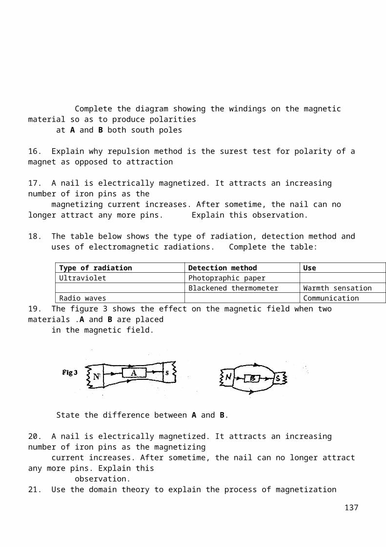
magnetic effect which tends to oppose the change causing it (b) (i) Resistance of the coil- remedy – thick copper coil ) (ii) Hysterosis loss– remedy – soft iron core (iii) Eddy currents – remedy – laminated iron core (iv) Poor flux linkage – Remedy winding primary coil and secondary coil on the same core
(c) VpIp = VsIs 12000 x 1 = 1800 x Is Is = 0.6667A Power loss = I2R = 0.66672 x 20 = 8.89w (3mks)
(d)
(correct diagram and six parts labelled correctly/ correct diagram and four parts labelled correct diagram and less than four parts labelled(1mk)Current enters the coil thorough the hair springs and flows into the core through the rectangular coils. This causes the coil to be magnetized. The magnetic field created cuts the radial magnetic field of the magnetat right angles. This causes the core to rotate. The rotation of the core is op-posed by the torque of the hair spring. When the force due to the rotation of the core is equal to the force due to the torque of the hair spring, the core comes to rest and the pointer gives the reading.
(e) (i)– Using a weak permanent magnet(ii) Using strong hair springs(iii) Using few turns of the rectangular coil
12.
13. Radiowaves, visible light, ultraviolet light;14. a) Induced current flows in such away as to oppose the charge producing it
b) i) P - brustiles Q- ship ringsii) X- North Y- Southiii)- Increasing speed of rotation of the coil
- Increasing the number of turns in the coil137
P
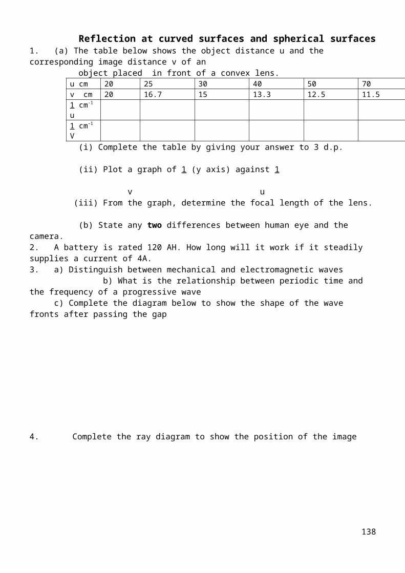
- Increasing the strength of the magnet
c) i) Efficiency = Power output X 100 % Power input80 = 48 X 13.5 X 100
Power inputPower input = 810w
ii) Power input = Ip X Vp 810 = 240 X IPIP = 3.375 A
15.
16. Repulsion occur between like poles, unlike poles and magnetic materials
Reflection at curved surfaces and spherical surfaces1. a) i)
1u
0.05 0.04 0.033 0.025 0.020 0.014
1v
0.05 0.06 0.67 0.75 0.080 0.086
Any 4 correct values = 1 mkTotal = 3 mks
iii) ₤ = 10 + 1 cmAny intercept = 1 mk
Rec. – 1 mkArrange of Reciprocal – 1 mk
b) – Focal length of eye lens is variable while that of camera is fixed. p1 mk] - Eye has constant image distance. p1 mk
2. 120 = 4tt = 120 p1 mk 4
= 30 hrs p1 mk3. a) Mechanical waves – require medium for propagation Electromagnetic can even travel in a vacuum (No medium required)
b) Frequency = 1/periodic time
c)
138

4.
Extrapolation of light rays backwardsDotted and upright change formed between C and F
5. Reflected rays shown by arrow pointed correctlyangles marked as i= r = 30o and i = r = 0 (implied), tar
6. Spherical aberration is a situation where rays parallel but far away (distant) from the principal axis of a concave mirrors fails to pass through its focal point owing to the large radius of curva-ture of the mirror
7. Complete the ray diagram below by showing the position of the image.-It is used as a simple microscope or magnifying glass in the laboratory.
8. - The reflection is a sheet of paper is irregular hence rays interfere with formation of images - Reflection in a plane mirror is regular
9. Advantage: wide field of vision Disadvantages: Gives a wrong impression of the position of image due to the diminished image formed
10. AxesScalePlotting all values
Plotting at least 5ptsLine
Magnification M
139
P 1P 1
P
r2
Image V distance( Vcm)
PP PPP
P

(b) From the graphV = mf + ff = V – intercept = 10cm
ORf = gradient = 50 – 20
4 – 1= 30
3= 10cm
Correct rays with arrowsObject between P and F
11. Image formed by concave mirror is enlarged while that formed by plane mirror is same size as object
12.
140
Magnification
PP
P
P 2
P
P P
13.
p1 for real rayp1 mk for virtual image
14. (a) (i) Point on the principal axis to which all rays originally close and parallel to the principal axis passes after reflection. (ii) Focal length (f) – distance between the pole of the mirror (centre of the mirror) and the principal focus f(b)
(c) (i) u = +12cm, f = +10cm, V=? 1/f = 1/u + 1/V , 1/10 – 1/12 = 1/V
12 – 10 = 2 120 120 \ V = 120 = 60cm 2 \Image distance = 60cm(d) (i) Enlarged, virtual, upright(any two)
(d) (ii)
2x – 320 = 0.8340 3402x – 0.94 = 0.83402x = 1.743402x = 591.6x = 295.8MLet the distance between the boy and the cliff be X and speed of sound in air is 340m/s
Linear motion1. Ft = m(V-U)
720x 0.1 = 0.6V V = 72 0.6 = 120ms-1
141
P 1
P 1
2.
Machines & inclined planes1. (a) - Energy is the ability to do work - Work is done when a force applied on an object moves it through a certain distance
(b) (i) V.R = 1 sin q = 1 Sin 30o
= 1 0.5 = 2 M.A x V.R = 75 x 2 = 150
(ii) Effort = Load M.A = 1500N 150 = 10N
Resistors1. – The ammeter should be in series - Voltmeter in parallel - Variable resistor in series - The apparatus must be workable2. a) ii) gradient = 10vp1 mk
0.5A= 20 W p1 mk
iii) 1 + 1 + 1 = 1 p1 mk 200 100 R 20
1 = 1 - 1 - 1
142
P 1
P 1
P 1
P 1
P 1
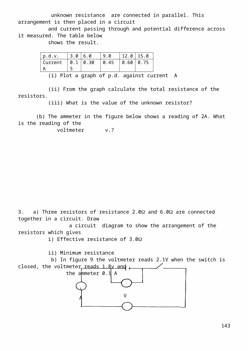
R 20 200 1001 = 9 p1 mk
9 200 = 20 W p1 mk
b) Current through 10 W resistor = 2Ap.d across 10 W resistor = 2 x 10
= 20vp.d. across 5 W = 20v
current = 20 = 4A p1 mk 5Total current 4 + 2 = 6A
Current through 2 W = 6Ap.d = 6 x 2 = 12V
Total voltage = 12 + 20 = 32V p
3. (i) (ii)
b) i) 2.1 Vii) 2.1 v – 1.8V = Ir = 0.1V r = 0.3 = 3
0.1iii) 0.1 X R = 1.8 V
R = 18R
4. - Length of conductor- Type /nature of material- Diameter/thickness of material b) E = IR + Ir
3.0 = I(3.5 + 0.5) = I (4.0) I = 0.75A5. a) – The current passing through a conductor is directly proportional to the potential difference across its ends provided temperature and other physical conditions are kept constant
6. I = 1 + 1 = 7 R 5 2 10 R = 10/7W
RT = 10 + 3 = 31W (Effective resistance) 7 1 7
but I = 12.4 x 7 = 2.8A 31
\p.d across the 3W resistor = 2.8 x 3 = 8.4V (p.d across the 3W resistor)\p.d across the 5W and 2W = 12.4 – 8.4 = 6.0V\Current across the 5W resistor = 6/5 = 1.2A (answer 3mks)
7. Rs = 3 + 4 Rp = 7 x 5 = 35 W 7 + 5 12 II = 6 x 12 = 2.057A 35
I through 3W resistor = I1
I1 x 5 = I2
143
P
P
P1
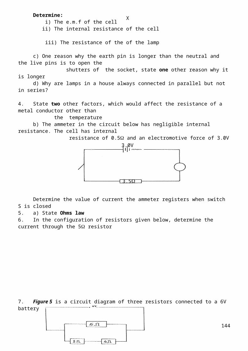
5(2.05 –I2).25 – 5I2
10.25 -5I2 = I2
6I2 = 10.25 – UI2= 10.25 = 1.708A 68. a) (ii)
(ii) Effective resistance:RE = 4 + 6 x 3
3 + 6 = 4 + 18 9 = 6W V = IR I = 12 = 2A 6
\V = 2 x 4 = 8V
(ii) V = 12 – 8 = 4V \V = IR
I = 4 = 2 = 0.667A 6 3
(iii) Effective resistance in parallel RE = 6 x 6 = 36 = 3W 6 + 6 12
The potential drop will increase; hence the reading of V will decrease
(c) (i) Step-down- The voltage is reduced from 240V to 8V (ii) To reduce loss of energy due to eddy currents
(iii) VP = Np Vs Vs 740 = 4800
8 VsVs = 4800 x 8 240= 20 x8 = 160turns
9 (i) – Set Galvanometer to zero balance by adjusting the variable resistor L. - P.d across BD is therefore zero - P.d across AB = P.d across AD
P.d across BC = p.d across DCI1 flows through K & L (I1 = I3)I2 flows through M and N (I2 = I4)I1K = I2MI3L = I4NI1K = I2MI1L I2NK = ML N
(ii) The method does not depend on the accuracy of the current measuring instrument
(b) R = 0.38 25W 0.62 R = 25 x 0.38
144
P1P1
PP
PP
P
P
P
P
P 1
P 1P 1P 1
P 1
P 1
P 1
P 1
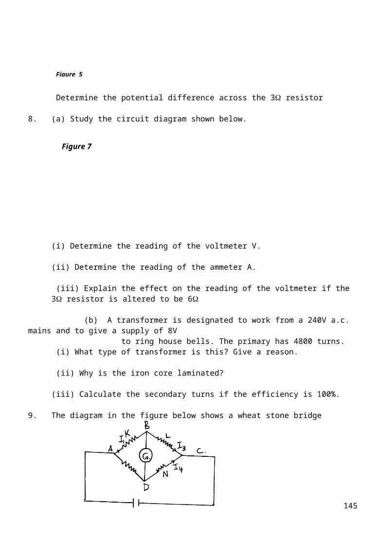
0.62 = 15.32W
10. C11 = 4mf + 5 mf = 9m fI = 1 + 1 +CT 3 9 33 + 1 + 3 = 7
9 9 CT = 9 = 1.29mF
11. (i) Minimum current is when y is at max resistance , i.e 100W (x and Y parallel) current I = 220V 100W = 2.2A
(ii) Maximum current is when R = 500W at y (when X and Y are parallel) I = 220V 50W = 4.4A
(c) (i) For the upper resistors in series R = 1 + 4= 5W for the lower resistors in series R = 2 + 3 =5W For the combined resistance of the parallel sets I = 1 + 1 = 2 R 5 5 5 R = 2.50W
Total resistance = 2.5 + 5.50W = 8.00W
(ii) Current 1y = 0.5A Vy = 40W x 0.25A = 1.0V V2 = 2W x 0.25A = 0.5V Vy2 = 0.5V *
(d) - Thickness/x-sectional area – Resistance is inversely proportional to the thickness of a conductor
- Length : Resistance is directly proportional to length of a conductor
Refraction of light1. ahp = 1.47 and ahg = 1.55
ghp= gha x ahp
= ahp
ahg
= 1.47 =0.9484 1.5
Sin C = 1 = 0.9484 h
C = sin-1(0.9484) C = 71.5o
2. (i) for incident and reflected ray(ii) The ray undergoes total internal reflection. Since angle of incident is greater than ao the critical angle.
145
P 1
P ½
P 1
P
P
P
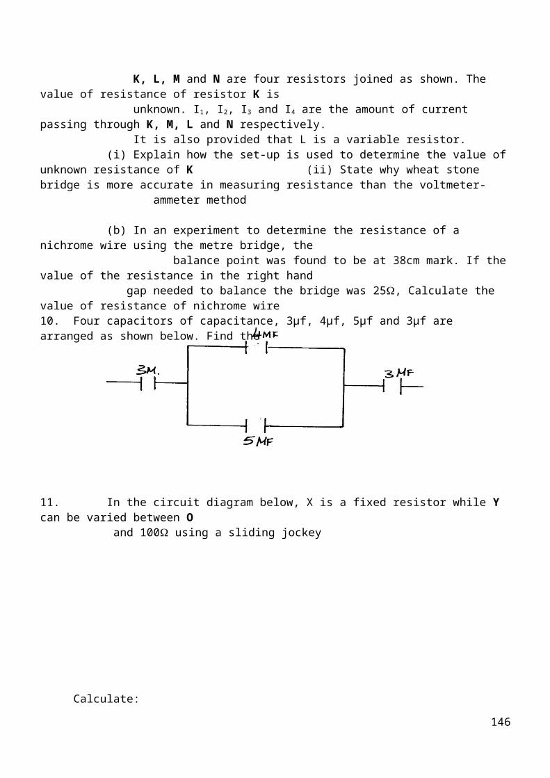
3. a) The ratio the sin Ø of the angle of incidence to the sin e of the angle of refraction is a constant for a pair of media b) When a ray is moving from an optically dense medium to a less optically dense
medium or when the angle of incidence in the optically dense medium is greater than the critical angle
c) ang = sin i/sin r
= sin 48°/sin 32°
= 1.40, Accept 1.402
d) Separation of colours of light from white light
4. gnw = gna x anw = 2/3 x 4/3
= 8/9 8/9 = sin q sin 40
sin q = 8/9sin 40 = 0.5713 = 34.84o
5. If the refractive index of medium 1 is 4/3 and that of medium 2 is 3/2. Calculate angle r n1sinq1 = n2 sinq2 4/3 sin 35 = 3/2 sinq2 sinq2 = 4/3 X 2/3 sin 35 = 0.5098 q2 = 30.654
6. a) iii) n = 1
sin 42 Sin 25 = I√
Sin r RSin 25 = sin 42√
Sin r Sin r = Sin 25
Sin 42 = 0.631593r = Sin -1 (0.631593) = 39.17° (accept 39.2°)√
7. (a) (i)-When a ray is moving from an optically denser medium to a less optically dense medium.- When the angle of incidence in the optically denser medium is greater than the critical angle (any 1)
(b) Sin C = n2 = 1.3 = 0.866 n1 1.5 ÐC = sin-10.866 \ÐC = 60.1o
(c) (i) From the len’s formula 1 = 1/V+ 1/u and dividing both sides by V, V = 1 + V/u , but V/u = M V/f = 1 + M and making M the subject ; M = V/f -1 (ii) Graph: - scale used (1mk) - Labeling axis - Straight line - Points - Gradient/slope
146
P
P
P P

1/V = 1/u – 1/f1/f = 1/u + 1/V or 1/V = 1/f – 1/u
Gradient = Negative1/V Intercept = 1/f
Sound II1. 2d = s x t T = 0.1s
d = s x t p1 OR f = 1 = 10Hz 2 0.1
= 330 x 0.1 p1 c = l f 2
= 330 = l x 10= 16.5 m p1 x = 33
But d = l = 33 d = 33 = 16.5
22. Velocity = s t = 220 x 2 1.29 = 341.085m/s3. Difference in time between the two points = 0.3 – 0.25 = 0.05secs.
Speed = D T
= 17m 0.5sec
= 340m/s4. At night, the mages of air close to the ground are cooler than those higher above. Sound
get refracted towards the earth5. - Place a clock near the end of one tube and point one open end towards a hard surface (wall) at an angle i
- With the ear close to the end of second tube, open tube T2, listen to the reflection of the sound from the wall at different angles of r and note where the sound is loudest-It will be observed that maximum (loudest) sound is heard when Ði=Ð r
6. – Light must travel from optically dense to less dense medium Ö - The angle of incidence must exceed the critical angleÖ
Thin lenses1. Short –sightedness or myopia
cause- the eye-ball is too long for the relaxed focal length
2.
147
P1
P1P1
P 1
P 1 P 1
PP
PP

b) i) I/F = I/U + I/VÖ 1/15 = 1/25 + I/VÖ V = 37.5cmÖii) U = 52.5 – 37.5 = 15cmÖ I/F = I/U + I/V
I/V = 1/30 - 1/15
= -30cm Ö3. (a) (i) - Candle placed at a distance u, from the lens and the position of the screen is adjusted until a sharp image is formed/obtained
- The distance, V, between the lens and screen is measured - The procedure is repeated to get other values of V and u - For each set of u and v the value of f is determined using the formula
(ii) The image would be virtual and cannot be formed on the screen (b) Extrapolate both sides of the graph and read-off
1 and 1 = 0.25 = ¼u v1 = 1 = f = 4 or f u1 =1 =f= 4f v
(c) M = u/v = 2
V = 2 15v = 30cm1 = 1 + 30 f = 10cm f 15 30
4. (a) (i) X – Intercept = 4.5 x 10¹⁴Hz (ii) Slope = h – h = e x slope e = e x 6.6 – 0)V (6-4.5) x 1014 s-1
= 1.610-19 x 4 x 10-15 = 6.4 x 10⁻³⁴Js
(iii) W0 =hf0
= 6.4 x 10-34 Js x 4.5 x 1014s-1 = 2.88 x 10⁻¹⁹J
(b) (i) The leaf falls Collapses (ii) The electrons are repelled causing the leaf potential to decrease (iii) NO effect on the leaf. Light emitted by red light doesn’t have enough energy to cause
photoelectric effect.148
P1
P1
P1
P1 P1P1
P1P1
P1
P1P1
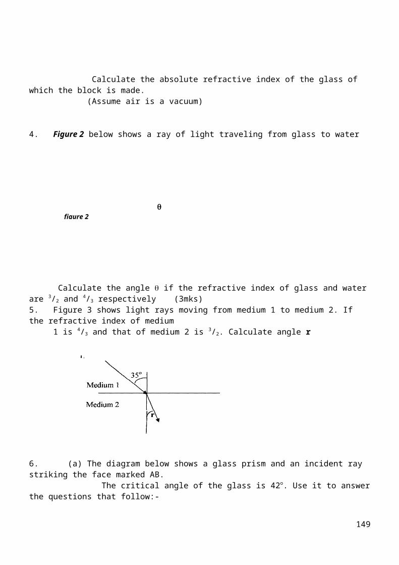
(iv) Light is a wave, it carries energy in small packets (protons).
5. (a) This distance is the focal length (b) Linear magnification is the ratio of image height to the object height or image distance to object distance Eye defect – short sightedness (myopia)
arrows object 6. a) By adjusting the lens’ position obtain a sharp image on the screen as shown above.
d = f
b) n = 5.5 X4 = 22cmm = 7X4 = 28 cmM = n = 22 = 0.7857
m 28 c) i)Long sightedness
ii)
7. f = -25cm, u= 20cm 1 = 1 + 1 f u v
-1 = 1 + 1 25 20 v
v = -20 -25 = -11.1cm 250
11.1 = h 20 10h = 5.56cm
8. (a)
149
P1 P1
P1P1
P
P
P
PPP

b (i) f = 30cm, v = 90cm 1+ 1 = 1 u v f 1 = 1 – 1 = 1 – 1
u f v 30 90 = 2 90
u = 45cm
(ii) m = v u
= 90 45 = 2
9.
10.
150
P
P
P
Fe
P
P
P
- Rays using lens Lo
Rays using Lens Le
Position of imagerge I1
Position image I 2
Quality of heat1. Heat lost by the metal = Heat gained by the water MmCm= MWCW 0.5 x CM(100-21)oC = 0.2 x 4200 x(21-15)oC Cm = 5040 = 127.59JKg-1K-1
39.5Waves II1. (a)(i) – Stationary wave:- waveform do not move through the medium and therefore energy is transferred from the source to the same point away.
- Progressive wave- wave forms more though the medium and therefore energy is transferred form the source t the same point away.
(ii) Open pipe has both odd and even harmonics.
(b) (i) For closed pipe ½ l = 0.6
l = 1.2ml V= fo, fo = V = (340)Hz = 283.3Hz
l 1.2(ii) For open pipe, one end open
End correction ignored,o If ¼ l = 0.6l = 0.6 x 4 = 2.4mfo = V = (340)Hz
2.4= 141.7Hz
.
2.
3. a) i) Sound is transmitted as a longitudinal wave electromagnetic is transmitted as a transverse wave. p1 mk
(ii) S = 2d p1 mk t
= 2 x 400 = 800 p1 mk 2.5 2.5 = 320m/s p1 mk iii) Let distance from mine worker be furthest cliff by y. then
S = 2d
151

t y = 1440320 = 2y p1 mk 2 2 x 2.5 = 720 m 2
2y = 320 x 4.5 total distance = 720 + 4002y = 1440 x = 1120m p1 mk
b) i) Bright fringe. p1 mk ii) Loud sound. p1 mkc) slat must be very narrow (less than the wavelength of light)
4. 6λ = 15 cm 1 λ = 1 x 15 p1 mk 6
= 2.5 cm. p1 mk
5. (a) i) = 8/2 = 4m f = V/X
= 340/4
= 80HZ
ii) T = I/F
= 1/80
= 0.0125 seconds √b)
6.
7. (a) In aprogressive wave, all particles have the same amplitude and each particle is out of phase with the particle next to it. In stationary wave, vibrations of particles at pooints between successive nodes are in phase and the ampllitude of particles between nodes is different
(b) Must have:- (i) Same speed (ii) Same frequency (iii) Same of nearly equal amplitudes
(c) OO1 – Loud sound (constructive interference) waves arrive in phase AA1 – Loud and soft sound (Destructive and constructive interference)
(d) f = V152
PP
PPP
PP
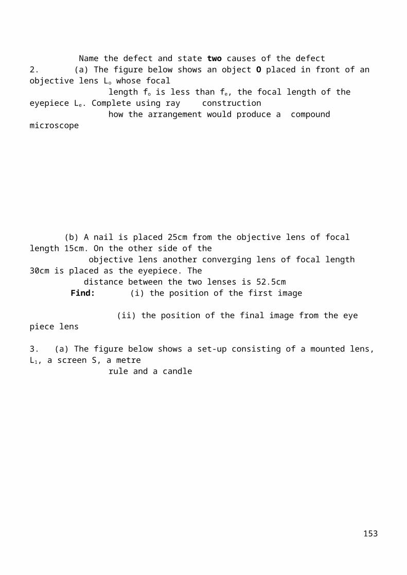
l l= 1.25 = 0.625 2 f = 50 0.625 = 80HZ
(e) – Constant phase difference - Nearly same amplitude
8. The width of the opening must be smaller than the wavelength of the wave.
9. - Diffraction- is the spreading waves beyond obstacle openings (1mk) - Refraction- is the bending of waves when they change the medium
10. Period T = 16 x 10-2 (read off) Frequency = 1/T
= 1/16x10-2 Hz = 6.25Hz
11. ½ oscillations = 0.2 seconds 0.2 seconds = 0.5 oscillations 1 second = 0.5 = 1 0.2 0.4 = ¼ x 10 = 0.25 x 10 = 2.5Hz
12. Time for one complete cycle = 0.5seconds\T = 0.5secondsf = 1
T = 1 0.5 = 2Hz13. From A to X is shallow since the ripples are close to one another. 14.
15. (a) (i) Electromagnetic waves travel though a vacuum while mechanical waves need a medium (ii) Mechanical waves – sound waves - water waves
- shock - electromagnetic waves – light waves
- radio waves -X-rays, gamma rays (any 1)
153
P
PP
PP1
P1P1
P 1
P 1
P 1
(b)
(c) (i)
(ii) f = 1 /T where f = focal length and T is the periodic time (iii) Radio reception is better because radio waves have longer wavelength hence easily diffracted unlike TV waves which have shorter wavelength
Work, energy and power1. D = 1V P I2R
I = P R = P V I2
= 45 p1 mk = 45 240 (0.1875)2 p1 mk
= 0.1875A = 45 = 1280W p1 mk 0.03515
2. P = V 2 R R = (240)2Ö 40 = 1440WÖ3. P = I V 3000 = 12A
250suitable fuse 13A
4. An electric kettle is rated 3KW, 250V. Determine the resistance of the coilP = IV = V2
R300 = 2502
R R = 62500
3000 = 20.83 W5. Energy E1 = Power x time
= 3000 x 8 x 60
154
P1P1
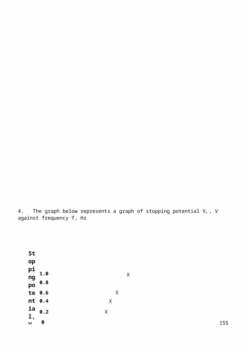
= 1440000J
6. = 2.4 x 4.2Jg-1K-1 x 46K (1mk) = 2.4 x 4200JKg-1 K-1 x 46K (1mk) = 463 6805J
Let the rime be t Energy H = Pt = 3450W x t
3450t = 463 680J t = 134.4s
Floating and sinking1. Production of electrons from metal surface when suitable heat energy falls on it.2. (a) (i) The weight of a fluid displaced by a body which is partially or wholly submerged is equal
to the upthrust experienced. (ii) A floating body displaces its own weight of the fluid it floats on (b) (i) Relative density = W Block – Wliquid
WBlock – W water
= 120-94 120 – 100 = 1.3
Density of liquid = 1.3 x 1000 = 1300Kg/m3
D = M V Mass = 20N = 2kg 10 Volume = 2kg = 0.002m3
1000 D = 2kg 0.002
Photoelectric effect1. a) i) – The emission of electrons from metal surface when radiation of unstable wave length falls on it Ö
ii) The maximum wavelength beyond which no photoelectric effect occurs Öb)
i) f = 6.4 x 10¹⁴H Öii) EK = hf –W h = gradientÖ = (6.2 – 22) x 10-19Ö
155
PP 1 P 1
P 1P 1
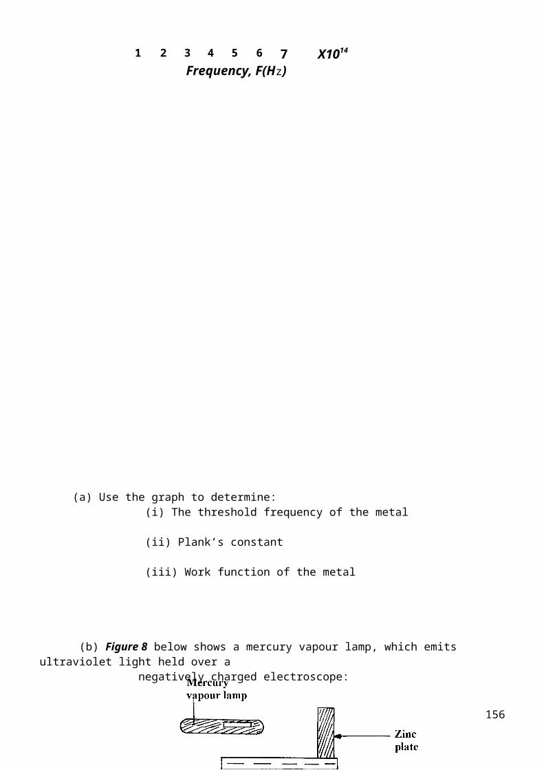
(16 – 10) x 1014
= 6.667 x 10⁻³⁴JsÖiii) Wo= hfo
= 6.667 x 6.4 x 1014 x 10-34Ö= 4.267 x 10⁻¹⁹JÖ
2. (a) (i) X – Intercept = 4.5 x 10¹⁴Hz (ii) Slope = h – h = e x slope e = e x 6.6 – 0)V (6-4.5) x 1014 s-1
= 1.610-19 x 4 x 10-15 = 6.4 x 10⁻³⁴Js
(iii) W0 =hf0
= 6.4 x 10-34 Js x 4.5 x 1014s-1 = 2.88 x 10⁻¹⁹J
(b) (i) The leaf falls Collapses (ii) The electrons are repelled causing the leaf potential to decrease (iii) NO effect on the leaf. Light emitted by red light doesn’t have enough energy to cause
photoelectric effect. (iv) Light is a wave, it carries energy in small packets (protons).
3. Calculate the wavelength of Green light whose energy is 3.37 x 10⁻¹⁹ J .(h = 6.63 x 10⁻³⁴JS, C = 3.0 x 10⁸m/s)
l = n ¦ = 3.37 X 10⁻¹⁹j l = 3.0 X10 8m/s ¦ 6.63 X 10 -34 5.083X10¹⁴HZ
= 5.08 3X10 14HZ = 5.902 X 10 -7m
¦ =E h4. a) This is the least radiation energy required to just dislodge an electron from a metal surface. b)The energy of the radiation. The higher the energy the higher the velocity of photo electrons
Frequency X 1014 Hz 7.959 7.43 6.88 6.10 5.49i) On the grid provided plot a graph of stopping potential (Y –axis) against frequency
Graph (diagram)ii) From your graph determine:
The threshold frequency ¦o = 4.5 X 10 14 HZ
b) The plank’s constant, h(e = 1.6 x 10⁻¹⁹ Coulomb, C = 3.0 x 10⁸ m/s)eVs =hf –hfo gradient = 1.15 – 0.93Vs = h f – h fo (7.43 -6.98) X 10 14
= 0.22 X 10 -14
gradient = h 0.55 e = 0.4 X10-14
= 0.4 X 10-14 X 1.602 X 10 -19 h = 6.408 X 10 -34js
5. a) It controls the intensity of electron leaving the electron gun controlling the brightness of the spot on the screen.
b) The magnetic field deflection system make electrons span the whole screen unlike the electric field deflection system.
156
P1
P1
P1
P1 P1P1
P1P1
P1
P1P1
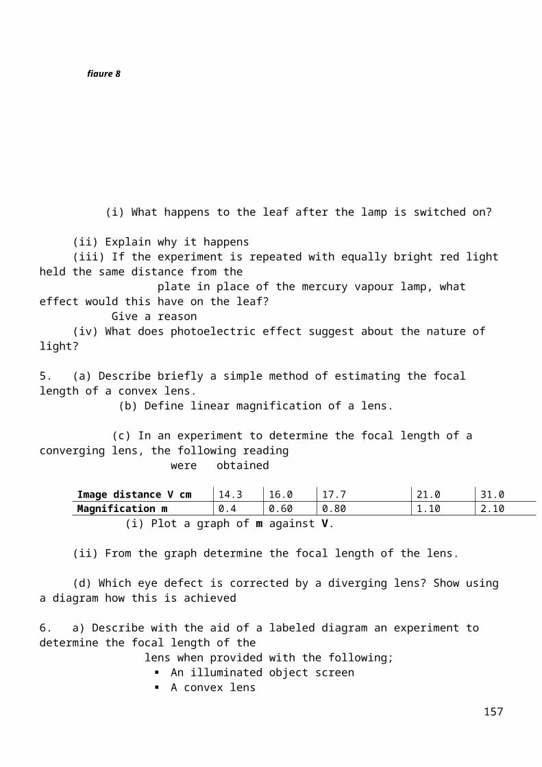
c) i) Calculate the frequency of the signalT = 25ms/div X 2 div f = 1 = 50 ms 50/1000 F = I T = 20HZ
ii) What is the peak voltage of the signalo peak voltage = 21X 2.5v|d.v
=5 Volts
6. (i) Graph is extrapolated to meet x-axis f0 = 7 x 10¹⁴Hz
(ii) Gradient = DVs Df = 1.75 – 0 12 – 7 = 1.75 = 0.35 x 10⁻¹⁴
5 x 1014 = 3.5 x 10⁻¹⁵
h = Gradient x e = 3.5 x 10-15 x 1.6 x 10-19
= 5.6 x 10⁻³⁴Js
(iii) W = hfo
= 5.6 x 10-34 x 7 x 1014
= 3.92 x 10⁻¹⁹ J
7. a) – Has infinite resistance/ does not take up any current - Sensitive/ does not require heating time b) i) A – Grid B- Electron gun ii) C – Vertical deflection of the beam D- Horizontal deflection of the beam iii) – By thermionic emission as heating the filament
8. a) Electrons being ejected from metal surfaces by use of electromagnetic waves b) i) X – intercept = 1.0 x 10¹⁵
ii) From K.E = hf Planks constant (h) = gradient of graph = (8.2 – 0) x 10 -19 (2.5 – 1.0) x 1015
= 8.2 x 10 -19 1.5 x 10¹⁵
H = 5.5 x 10⁻³⁴ JS
iii) Work function, W0 = 5.5 x 10-34 x 1.0 x 10 = 5.5 x 10⁻¹⁹ J
9. (a) (i)
157
P 1P 1
P 1
P 1
P 1P 1
P 1
P 1
PP
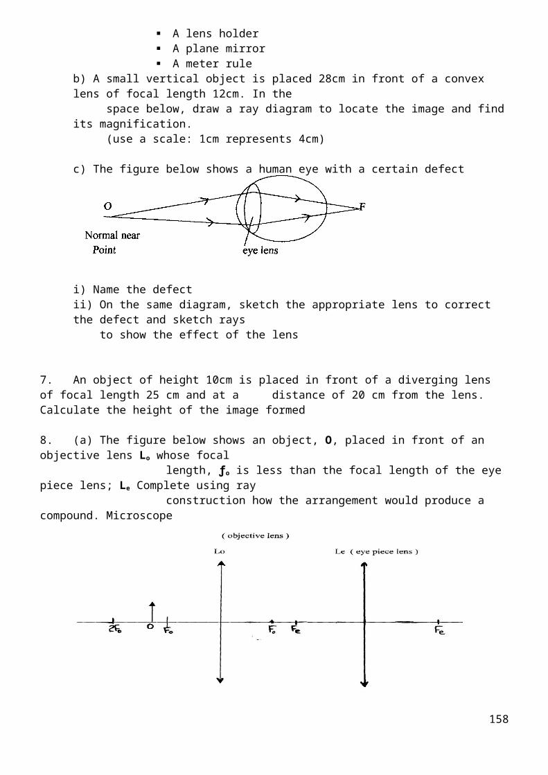
Correct polarity(ii) No change in the amount of photo current. Change in wavelength/frequency of the radiation does not affect the amount of photo electrons produced. It is the number of
photo electrons that determines the photocurrent.
(b) (i) Total resistance = gradient = 7.5 – 0 = 20W 0.375 – 0
(ii) Combine d resistance = 100R 100 + R
100R = 20 100 + R 100R = 20R + 2000 80R = 2000 R = 25W
(c) (i) Alternating magnetic flux in the coil induces current in the core of the same coil causing eddy currents. - Eddy currents are minimized by lamination of the core
(ii) Vs = Ns = 8 = Ns Ns = 4200 x 8 Xp Np 240 4200 240 10 - Intensity of the radiation
- Energy of the radiation- Type of the metal
Ns = 140turns11. a)i) Emission of electrons from metal surface by electromagnetic radiation falling on the surface
b) ii) M= u = 0.56 – 0 = 0.56 = 40 X 10 -15
e (6-4.6) x1014 1.4 X 10¹⁴
h = 4.0 X 10-15 X 1.6 X 10 -19 = 6.4 X 10⁻³⁴ Jl
c) hf = Q + K.E6.4 X 10-34 X 3.0 X 1015 = 6.4 X 10 -19 + K.E
K.E = 19.2 X 10⁻¹⁹ – 6.4 X 10-19
= (19.2 – 6.4) X 10-19
= 12.8 X 10-19
= 1.28 X 10⁻¹⁸ J
ELECTRICITY & Electronics1. From acceleration a = V-u and making V the subject ; V = at + u or V = ut + at
2. Polarisation p1 - Corrected by adding a depolarizer p1 158
PP
PP
P
P
P
P P
P

Or local adic - Corrected by amalgamation or use of pure zinc.
3. RT = 4.5(4.5) Ö 9 = 2.25W I = V R1
= 6 2.25 = 2.667A Ö
4. i) ii) Straight vertical line observed since Y- gain is connected leading to vertical deflection
5. Y - Neutral Z – Live Ö
6. – Decreasing area of overlapÖ - Removal of dielectric Ö - Increasing separation distance Ö
(a) (i) For W to occupy a smaller space(ii) Ofers high resistance
(b) (i) To reduce power loss for long distance power transmission (ii) To be able to step it up or down depending on need
(c) – High current/charge carrying capacity/density - Lighter
(d) (i)
(ii) Melts and breaks the current if there is an overload to protect the load connected to the main output
(e) Power consumed for 30days = 1.5 x 2 x 30 = 90KW Cost of the electricity cnsumed= 90KW x 6.70= Kshs.603
8. (a) (i) Z – Zinc plate Y – Dilute sulphuric acid (ii) – Local action
- Occurs due to the reaction between Zinc plate and dilute sulpuric acid thus Zinc is eaten away (iii) Use of depolariser (Potassium dichromate)
159
P P
P
PP
PP
P
PPP
PP
P

(b) (i) Doping intrinsic semi-conductor with group III elements
(ii) PQ
(iii)
9. Conductivity increases with increase in temperature. Increase in temperature makes valance elec-trons gain kinetic energy and jump to the conduction band
10. (all diagram correct) (2mks)
11. A 1 shows a deflection while A2 doesn’t. This is because diode P is forward biased while Q is reverse biased i.e it offers high resistance.
12. - Eight dry cells have a very high internal resistance compared to the car battery hence very little current can be drawn from the dry cells.
13. a)i) p –type :- it is obtained by dopping an intrinsic semi conductor using a group 3 impurity. n– type :- it is obtained by dopping an intrinsic semi conductor using a group 5 impurity ii) The figure below shows a bridge rectifier
A capacitor has been connected across the resistors as shown. Sketch on the axes below the wave form when a C-R-O is connected across the resistor; R
b) e.m.f = 1.5 v160
P
P 1
P 1
P

ii)Terminal voltage = 1.25viii) Calculate the internal resistance of the cell
e = I (r +R) I = 1.25 I .5v= 1r + 1.25 4.8 I r = 1.5 -1.25 = 0.2604Λ I r = 0.25v r = 0.25 0.2604 But I = 1.25 = 0.96W R14. A fuse is a safety device is used to disconnect the circuit when excess current flows
through it, it melts.15. Distinguish between Topping and Dopping
Topping:- The addition of distilled water into a lead acid accumulator to improve on the ion concentration.Dopping:- Addition of impurities to an intrinsic semiconductors to improve on its conductivity.
16. a) A is Copper B is a dilute acid (hydrochloric or sulphuric acid)b) - Polarization - Local Action
17. a) Cathode:- Zincb) two causes of this observation. Due to defects that the cell suffers. These are Local action. The eating away of Zinc (cathode) by the acid.
Polarization:- the formation of H2 bubbles at the anode insulating it.18. –Colour televisions have three electron guns compared to one in black and white televisions19. – Capacitance is inversely proportional to the distance of separation between the plates (1mk) - Capacitance is directly proportional by the area of overlap between he plates (1mk)20. a) i) Local action ii) Polarization
b) – Connect the three bulbs in parallel so that their infernal resistance is reduced. - This arrangement increases the current making the bulbs very bright21.
22. To increase the conductivity of a semi-conductor23. (a) Forward biased (b) Resistance in the circuit is varied by moving the jockey along R. - A series of values of voltage for the corresponding values of current are obtained (c) (iii) They are not deflected by both electric and magnetic fields
(iv) Alpha particles are heavy (massive) (v) The sheets are brought in turns between radioactive source and the counter.
- The count rate is a measure of the thickness of the metal sheet.24. a) Q1 = CV = 0.3 F X 4.5 = 13.5c
b) CT = C1 + C2 (0.3 + 0.5) F= 0.8F
161
P
PPP
PP PPP
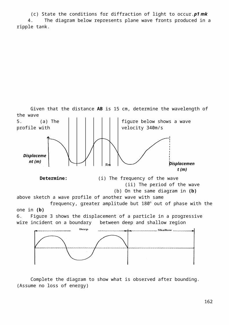
c) i) 4.5Vii) Voltmeter reads less than 4.5V iii) The drop of p.d in C (ii) is because the charge on C1 is because is distributed to C2.
Since values of C1 and C2 remain constant when Q on C1 reduces, the Q = C1V implies V must reduce also, hence reading reduced25. (a) Ability of a capacitor to store charge (b) (i) For charge distribution
Raised leaf
(ii) The leaf divergence increased. The potential on of increases due to reduced capacitance since distance of separation is increased.
(iii) They are not deflected by both electric and magnetic fields(iv) Alpha particles are heavy (massive)
(v) The sheets are brought in turns between radioactive source and the counter.- The count rate is a measure of the thickness of the metal sheet.
26. a) – Area of the plates - Distance of separation of the plates - The electric constant b) – Capacitors in parallel 1mF + 2mF + 3mF = 6mF - Capacitors in series: 1/
6MF + 1/3MF = 2F
Q = CV = 2.0 x 10-6 F x 10v = 2.0 x 10⁻⁵ C27. a) – The process in which an impurity is introduced into a pure semi- conductor b) – Intrinsic – pure semi- conductors where charge carriers come from within - Extrinsic – pure semi- conductor which has been doped c) Bulb B2 lights 28. a) Define Eddy currents
These are current loops that develop in the core there is a change in the magnetic field linking with the core.
b) i) Using Lenz’s law indicate the direction of current through the galvanometer
ii) I. The magnet is moved away from the solenoid The deflection of the galvanometer changes since direction of current is opposite the pre-
vious oneII. The magnet is placed stationary in the solenoid.
o The galvanometer does not deflect since no current flows
c)The p.d a cross the primary coil is 240V
Np = Vp = 240 VBC = 6 X 20VNs Vs Vs 9
12 = 240 =120 Vs 9
162
P PP
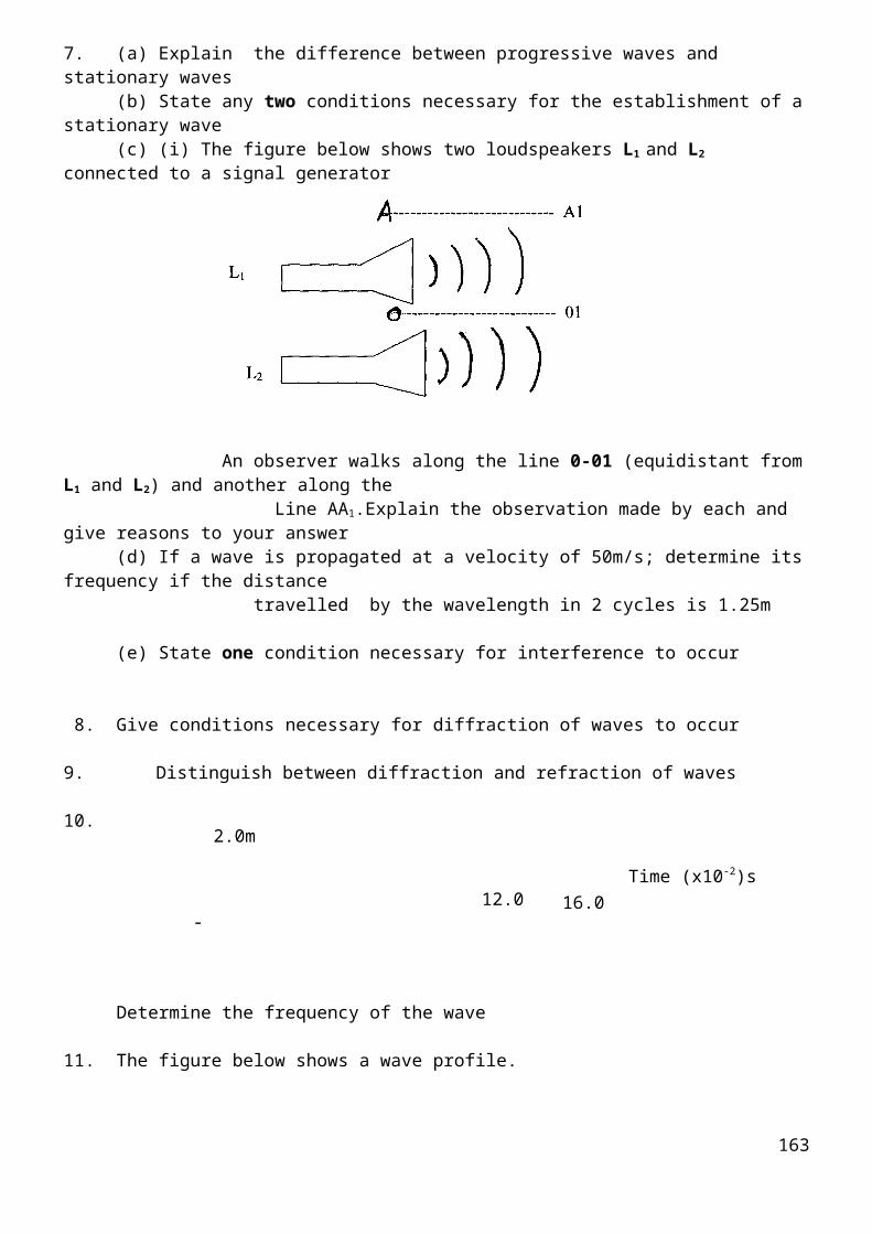
Vs = 240 = 13.33 12 = 20V
d) i)It lights because during the rotation of the wheel there is an indication of part (i) the coil creating a current that flows through the bulb and it lightsii) By making the wheel rotate faster or by making bicycle more faster
29. Evaporation and cell reaction cause loss of water. Distilled water does not introduce impurities to the cell
30.
X-ray1. Treatment of cancer, tumors2. (i) Size of heater current/filament current
(ii) Accelerating potential/kinetic energy of elctrons/anode Voltage3. To avoid collisions between the moving electrons and air particles4. a) – Tang stein has high melting point and therefore it would not met at elevated temperatures b) – Increasing filament voltage or heating current 5. a) Micro waves, infrared, ultra violet X – rays b) i) A – X – rays B – visible light ii) - X – rays – viewing bone fracture/ foreign objects in the body - Visible light – ordinary photography/ optical fibre6. (a)
(b) - To direct x-rays out of the tube through the window on the shield.(c) - Tungsten or molybodenum.
- High melting point thus it can withstand high temperature.
(d) (i) Heater current (Filament current) (ii) Anode potential (operating potential) (iii) - Covering with protective materials where x-rays are not required
- Minimize exposure time as much as possible- Reduce number of exposure as much as possible (any 1-1mk
(e) (i) Q = Jt = 10 x 10-3C (= 1.6 x 10⁻¹⁹C) 10 x 10-3C = 1.6 x 10⁻¹⁹ x n
n = 10x 10 -3 = 6.25 x 10¹⁶ electrons 1.6 x 10⁻¹⁹
(ii) ½ meV2 = eV
V = 2eV me
163
P
P1P1
P1
P1P1
P1

= 2 x 1.6 x 10-19 x 12000 9.1 x 10-31
= 4.2198 x 1015
= 6.496 x 10⁷m/s
(iii) - Detecting fault in metals or other structures. - Controls quality of manufacturer items e.g tyres, thickness of sheets, papers e.t.c. - Analysis of gem stones. (Any one-1mk
7. (a) A – cathode B – Anode C – Cooling fins (b) (i) increase the p.d at the anode (B) (ii) : increase the cathode heater current
(c) Tungsten:- It has a high melting point so the heat produced will not melt it easily(d) Copper – it is used to cool/conduct heat away from the anode(e) So that the electrons do not collide with gas molecules which could result in loss of energy.(f) (i)Detecting fracture in bones
(ii) Detecting flaws in metals
8. a) i) Name the part labeled C and state its function C is the cathode. It produces electron thermionicallyiii) (Take electric charge e = 1.602 x10⁻¹⁹C, planks constant h = 6.63 x 10⁻³⁴ Js, and speed of light c = 3.0 x 10⁸m/s
Energy of X –rays f = 8.01 X 10⁻¹⁶
£ = 5/100 X 100 kV X 1.602 X 10 -19 c 6.63 X 10 - 34
= 8.01 X 10 -16 j = 1.208 X 10 18 HZ l = c l = 3.0 X10⁸ m/s f 1.208 X 10¹⁸HZ
= 2.483 X10 -10miv)- They penetrate matter
-They obey properties of electromagnetic waveso Diffractiono Reflectiono Obey inverse square law
v) -Used to detect defects in metals in industries -Used to sterilize medical equipment.
9. i) K- X ii) X = 88 Y= 288
Radioactivity1. a) Radioactive decay is the spontaneous random emission of particles from the nucleus of an unstable nuclide
(b) There are 7 half lives ( t½ )7t½ = 49 dayst½ = 49
7 = 7days
2. (a)(i)Position of diodeIndication of a.c source
164
P1
P1
P
P
P
PP
P
PP

Complete and correct circuit
(ii) During the first half cycle, the diode is forward biased so it conducts. - Current flows through R2 building a voltage which decreases as the first half cycle comes to an end. - During the second half cycle, the diode is traverse biased so it does not conduct.
(b) (i) y =238-4(1) = 242 X = g2 (ii) 120 = 6 half lives 20
0.03125 x 26 = 2g(iii) They are deflected by both electric and magnetic fields(iv) Alpha particles are heavy (massive)(v) – The sheets are brought in turns between radioactive source and the counter. - The count rate is a measure of the thickness of the metal sheet.
3. a) Spontaneous disintegration of unstable atoms in order to gain stability b) i) a = 236 – 91= 145 ii) b = 92- 38 = 54 c) radioactive substances are harmful to the body when ingested d) i) Negative ii)A – Beta radiation C – Alpha radiation iii) C – more massive than A
e) i) A = 233 – 8 = 225 ii) Z = 90 – [(2 x2) + (2x – 1)] = 90 – (4 – 2) = 90 – 2 = 88 f) – a beta source is placed on one side of a moving sheet of paper and a G.N detector on the other side - If the material is too thin, the count rate at the detector will be too high and vice versa 4. (i) S – 210 T – 206 (ii) The splitting of a heavy nuclide to lighter particles (fission process)5. State what type of radioactive decay this is. - Alpha decay
a) X…4 Y…26. Long radio waves, AM radio waves, T.V and FM Radio waves, short Radio waves, infra red radiation, red-light , Uv radiation and X-rays.7. No. of half lifes = 380 = 10 38 N = No (½ ) 380 = (½)10 = 1 38 10248. (a) Time taken for the activity of a sample of a radioactive material to reduce to half of the original value (b) (i) S – scale – simple and uniform / consistent p – Plotting at least 4 points correct C – Line must pass through at least 3 points (ii) -Half-life 319 ±0.1 days (1mk) -Readings –off from the graph clearly
(c)
Time Nuclei 0 8 x 10¹⁰
138 4 x 10¹⁰
165
P
P 1P 1
P1/t
P
P
P

276 2 x 10¹⁰
414 1 x 10¹⁰
552 0.5 x 10¹⁰
690 0.25 x 10¹⁰
Therefore Nuclei remaining un-decayed T/t= 2.5x 10⁹ (1mk)
OR N = No (½ )½ N = 8x10¹⁰(½) = 0.25 x 1010 = 2.5 x 10⁹ (2mks)
(d) (i) mass number = 228 a.m.u (1mk) Atomic number = 89 a.m.u (1mk)
(ii)
SECTION III QUESTIONS
KAKAMEGA CENTRAL DISTRICTQuestion 1You are provided with the following apparatus;
- A wooden plank of length 1m or a meter rule- A meter rule- A half- meter (can be shared)- Two complete retort stands- Some thread- A stop watch/ clock Proceed as follows:-
1 a) Set up the apparatus as shown. Ensure the loops on the wooden plank and meter rule are loose to enable easy sliding of the threads. The separation between the meter rule and the plank must remain 20cm throughout
the experiment.
b) i) Adjust the positions of the thread such that one is at the 10cm mark and the other at the 90cm mark so that the distance marked d is 80cm. Maintain the threads vertical by moving the loops on the plank.
ii) Now displace one end of the meter rule slightly on a horizontal plane so that when released it oscillates about a vertical axis as in the figure below.
166
P
iii) Measure the timer for 10 oscillations and record the value in the table provided belowc) i) Repeat the procedure in (b) above for the values of d shown in the table (set the values of d by adjusting the positions of the loops in steps of 5cm on both sides)
ii) Complete the tableD (cm) D (m) 1/d2 (M-2) Time for 10 oscillations Period T (s) T2 (S2)80706050403020
d) i) On the grid provided, plot a graph of T2 (y – axis) against 1/d2 (M-2) ii) Determine the slope of your graph
iii) Given that T2 = 16K 2 where K is a constant. Use the graph to determine the value of K 5d2
QUESTION 2This question has two parts A and B. Answer both parts.You are provided with the following: - A lens and a lens holder- A candle- Object consisting of a hole 2cm in diameter and parallel wires 1.5cm apart in a stiff card.
(See diagram below)- A screen- A meter rule
Proceed as follows:-a) Illuminate the object with the candle flame. b) Arrange the object, lens and screen in line as shown in figure 3 below
167

c) Measure the distance, d, between the two parallel wire that acts as the objectd = ………………… cm
d) Adjust the lens, u to 80cme) Move the screen until a clear image is formed on it.f) Measure the distance, X, of the image, making sure that what you measure is an image corresponding to the previous reading, d.
Record these values in the table below:-g) Repeat your readings of x with u = 70, 60, 50, 40 and 30cm and complete the table
U (cm) 80 70 60 50 40 30X(cm)d/ x
h) i) On the grid provided plot a graph of u (y – axis) against d/x
ii) I . Determine the slope, S of the graphII. Find the intercept on the u – axis
PART BYou are provided with the following:- - A jockey J- An ammeter- A voltmeter- A switch- 6 connecting wires, Z with crocodile clips on one end- A resistor wire labeled XY mounted on a piece of wood having a millimeter scale- 2 new dry cells
Proceed as follow:I) i) Connect the circuit as shown below:
ii) Close the switch and note the voltmeter and ammeter readings when XJ = 10cmiii) Repeat procedure (i) and (ii) above with XJ = 20 cm and enter in the table 3 as below: *KKC*
Table 3:-Length XJ (cm) P.d.V . (v) Current, I (A)
168

1020
J) Given that log I = n log V + log k, where k and n are constants, determine the values of k and n
KAKAMEGA EAST DISTRICT
1. You are provided with: - Mass M- One 100g mass - Metre rule- Cotton thread (3 –pieces each about 30cm long) - Retort stand and clamp- 250cm3 glass beaker- 200cm3 of water
(a) (i) The loops of thread on solid M and the 100g mass (ii) Suspend the metre rule on the clamp from the 50cm mark (iii) Hang mass m from the mark. Balance the metre rule using the 100g mass (see fig. 1 below)
(iv) Measure the distance X and X1 from the 50cm mark (v) Repeat the procedures for the values of X indicated in the able below:
X(cm) X1(cm) X2(cm) X1 –X2 (cm)454035302520
(b) (i) Repeat steps (a) (iii) to (a) (iv) above, but this time, keep mass M totally immersed in water. Record distance X2 required to balance the 100g mass in the table above.
169
(ii) Complete the table for the values of (X1- X2)(c) (i) Plot a graph of X1 (Vertical axis) against (X1-X2) on the grid provided (ii) Determine the slope S of your graph (iii) What physical property does the slope, S represent? (iv) Given that the density of water is 1000kg/m3, determine the density of mass, M (d) (i) Using the apparatus you were given, determine the mass of your metre rule (ii) Draw a diagram of the set-up of the apparatus you have used to work out (d) (i) above
2. You are provided with the following:- - Two dry cells (size D) - 1M long nichrome wire (S.W.G 28) labelled AB- Ten connecting wires, one of length 70cm having a jockey- A micrometer screw gauge- A torch bulb- An ammeter (0 10A) - A voltmeter (0 – 3V) - Switch
Proceed as follows:- (a) (i) Set-up the circuit below:
fig 2
(ii) With the jockey (J) at X i.e L = 100cm, record the voltmeter reading, and the ammeter reading I. Repeat the readings for L = 80, 60, 40, 20, and 0cm and enter your results in the table below:
L(cm) 100 80 60 40 20 0P.d V(Volts)Current I (A)
(b) (i) Plot a graph of p.d V (y-axis) against the ammeter reading , I
(ii) Determine the slope of your graph when V = 0.5volts (iii) What physical quantity does the slope in (ii) above represent? (c) (i) Given the apparatus above, draw a diagram of the circuit you would use to determine the current through the resistance wire, AB and the p.d across it when the cells are now in series (ii) Set-up the circuit you have just drawn and record the current I and p.d V when L = 100cm (iii)Using the micrometer screw gauge, measure the diameter d of the wire, AB d = ___________________________mm (iv) Calculate the quantity, S, given that: S = pVd 2 4I L (Take p = 3.14)
Give the units of S
170
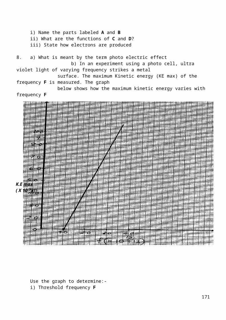
MIGORI/NYATIKE DISTRICT
Q.1 You are provided with the following apparatus:- - 600 ml beaker. - A measuring cylinder (100ml). - Plasticine. - A meter rule. - Distilled water supplied in a 500 ml wash bottle. - Candle. - Screen. - Tissue paper, 30 cm ruler
Proceed as follows:- a i) Add 310 ml of water to the beaker and obtain h, the height in cm of the water above
the base of the beaker. h = …………………………………. cm ii) Calculate an approximate value of R, the internal radius in cm from the formula.
R = 100 h
b) i) Fill the beaker with more water and set up the apparatus as shown in figure 1. The vessel should be placed at around 50 cm mark on the scale.
ii) Starting with 1OR, adjust the screen until you see a sharp bright vertical line. iii) Record the distance V of the image in table 1 whose image is sharpest. Repeat the experiment with values of u between 1OR and 3R cm.u 3R 4R 5R 6R 7R 8R 9R 10Ru (cm)v (cm)
c) Plot the graph of u against v. d) From the graph determine.
i) v1 the value of v for which v = u. ii) u1 the value of u for which u = 2v.e) Calculate f, the effective focal length of the ‘lens’ from the formula.
f = u 1 + u 1 5
f) Give the approximate value of R/f .
Q2. Part A. You are provided with the following apparatus:- Boiling tube. A cork with a hole and a thermometer to fit in it. Complete retort stand. Source of heat. Some distilled water in a beaker.
171
Figure 1
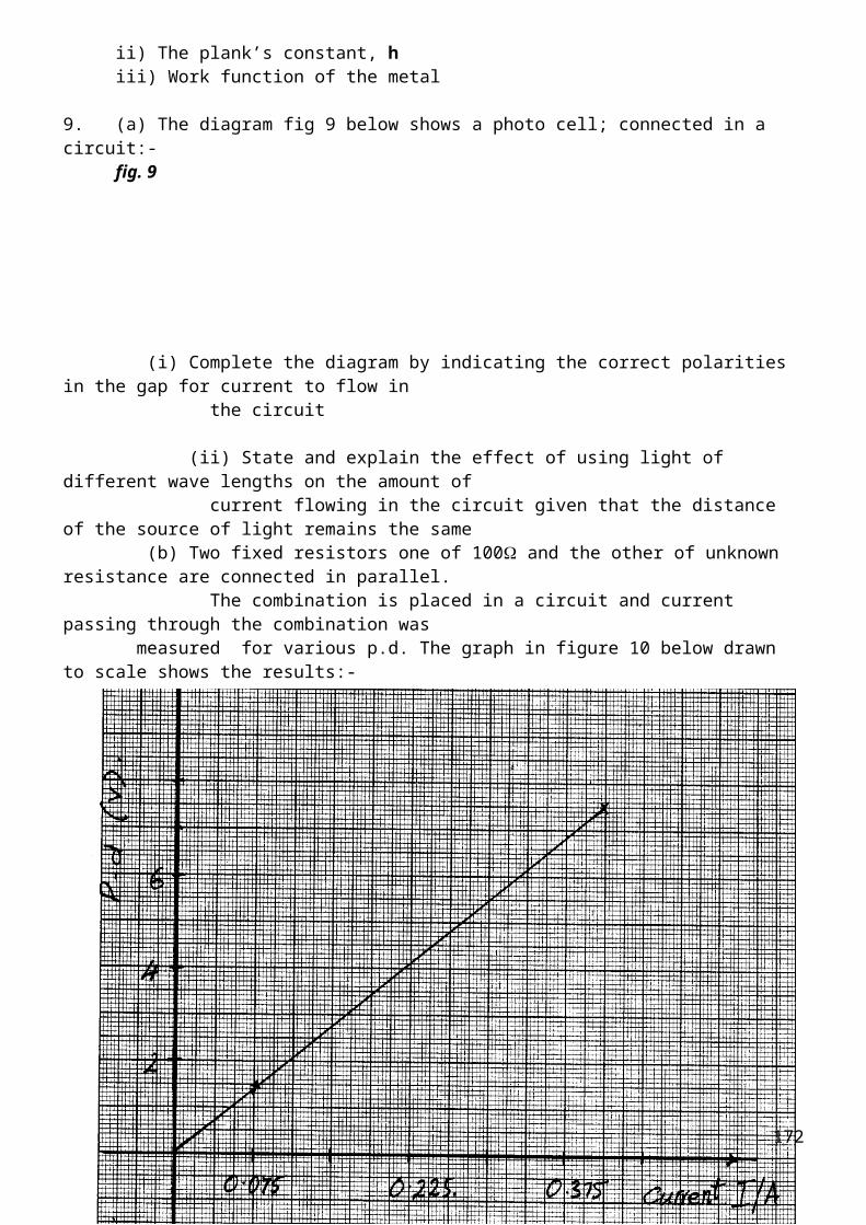
Stop-watch. Tissue paper. 250ml beaker.
Proceed as follows:-a) Heat the water in a beaker until it boils. It is essential that the water is kept boiling throughout the experiment. b) Clamp the boiling tube as shown in figure 2 making sure that the tube does not touch the
base of the retort stand.
figure 3 figure 2
c) Using a 250 ml beaker, transfer some boiling water into the boiling tube making sure that some space is left. Plug the tube with the cork that carries the thermometer as shown in figure 3. d) Starting with the temperature of 80oC, note the temperature of the water every 1 minute i) Tabulate your results in a table as shown below:-
ii) Plot a graph of temperature q (oC), against t, min. iii)Find the gradient d q of your graph at the temperature of 70oC
dt . iv) Find the rate of heat loss, R, at the temperature of 70oC given that
R = K d q where K = 1.23 x 10⁴
dt
Q.2 Part BYou are provided with the following:- Two New identical dry cells (size D) Nichrome wire labelled AB, mounted on a metre rule. An ammeter (0 – 1.5A) or (0 - 2.5A). A voltmeter 0 – 5V. A cell holder. 8 connecting wires at least 4 with crocodile clips. Jockey. A switch
Proceed as follows:-a) Connect the circuit as shown in figure 4 below
172
Figure 4
Time t (min) 0 1 2 3 4 5 6 7 8 9 10Temperature (oC)
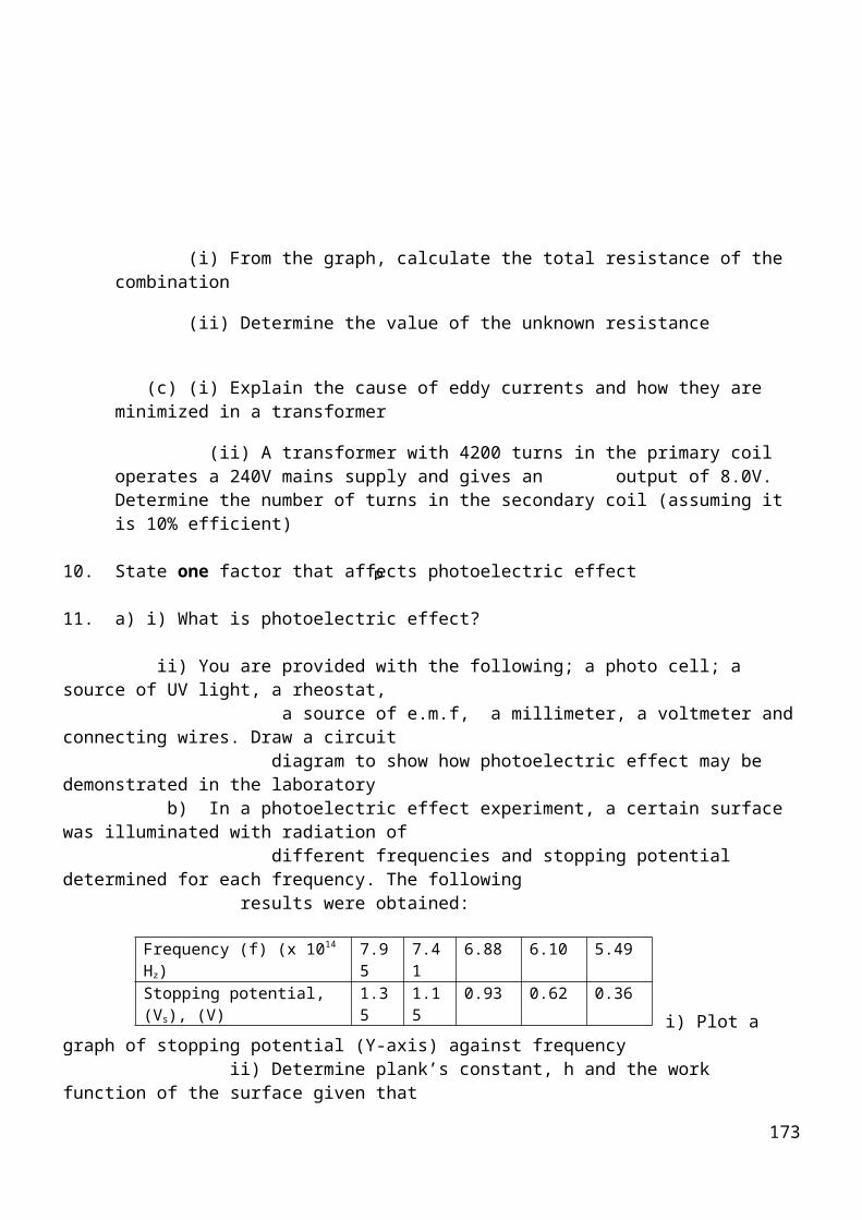
b) Connect the end A and B where AB = 100 cm across the terminals as shown in figure 4.
Close the switch and measure both I and p.d., v across the wire AB.
i) Current I = ……………………………………………………………A
ii) p.d. V = ………………………………………………………………V
iii) Measure the e.m.f. of the cells, E = ……………………………….. V
iv) Given that equation E = V + Ir, determine the internal resistance of the two cells.
SOTIK DISTRICT1. You are provided with the following apparatus:-
Micrometer screw gauge Vernier caliper Water in a beaker 1000ml(should be ½ full) Long test-tube Some dry sand Spatula Millimetre scale marked on a paper strip Some cellotape 6 ball bearings
Proceed as follows:-(i) Measure and record the diameter d of one ball bearing using micrometer screw gauge
d = ____________________cm (ii) Determine the volume V of the spherical ball bearing
V = ___________________cm3
(iii) Measure the inside diameter d of the test-tube using vernier caliper. Record it below: d = __________________cm
(iv) Find the cross-section area A of the test tube A = ____________ cm2
(b) (i) Place the millimeter scale along the height of the test tube so that the zero is at the bottom (ii) Place the test-tube in the water carefully and add sand bit by bit until it floats while vertically upright in the water as shown:-
173
BA
Millimeter scale Beaker
Test tube
hcm Water

(iii) Note and record the height ho of water level by use of attached millimeter scale ho = ______________cm (c) Add one ball bearing into the tube, note and record the new level h in the table of results below: (d) Repeat step (c) with two, three, four, five & six ball bearings and record their corresponding h(cm). Compute values of h-ho(cm) in the table below:-
No. of Ball Bearing (N) Floating level h(cm) h – ho(cm)123456
(e) Plot a graph of h-ho(cm) against the number of ball bearings (N) (f) Determine the slope S, of the graph(g) Relative density Ps, of ball bearing is given by:
Ps = SA. Find Ps
V
2. PART IYou are provided with the following apparatus:- Rectangular glass block Four optical pins Plain paper Soft board Piece of cellotape
Proceed as follows:- (a) (i) Use cellotape provided to hold the sheet of plain paper on the soft board
(ii) Place the glass block on the middle of plain paper and with a sharp pencil, draw its outline ABCD as shown:-
174
Sand
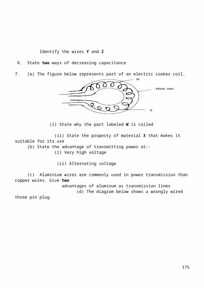
(b) (i) Construct the normal on side AB, but close to A. Use protractor and ruler to draw an incident ray with an angle of incidence = 10o (ii) Insert pins P1 and P2 along the path drawn. Viewing through the glass block on side CD,
locate P3 and P4 such that P3 P4 appear in line with images of P1 and P2
(iii) Produce P1P2 to obtain a lateral displacement as shown in the figure below:- Measure angle of refraction r, and lateral displacement
(c) Repeat steps (b)(ii) and (b)(iii) for angles of incidence i = 20o, 30o, 40o, 50o and 60o. Tabulate your results as shown in the table:- Note: (You must handover your workings on the plain paper with the question paper after the session)
(d) Plot a graph of lateral displacement, d, against angle of refraction r2. PART II
You are provided with the following:- An ammeter (0- 1A) A voltmeter (0-2.5V or 0-5V) Two dry cells A mounted resistance wire Eight connecting wires, two with crocodile clips A three volts torch bulb in a bulb holder A cell holder A switch A jockey or a crocodile clip
(a) Set-up the apparatus as shown below:-
175
P2P1
r
P3
Switch Cells
Angle of incidence i 20o 30o 40o 50o 60o
Angle of refraction Lateral displacement
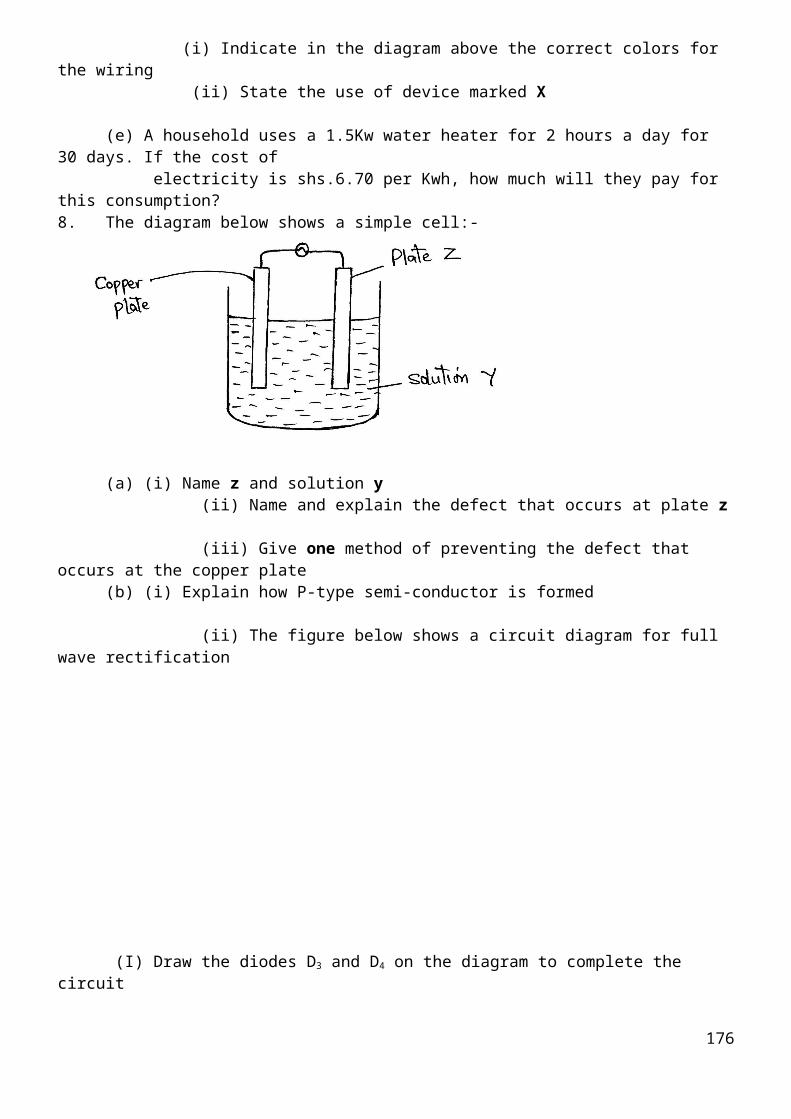
(b) With the jockey or crocodile clip at C, 30cm, 50cm and 70cm, record their corresponding V1, V2 and V3
(c) Replace the voltmeter with a torch bulb and an ammeter. Connect in series as shown in the circuit diagram:-
(d) Read and record the ammeter reading I1, I2 and I3 for the corresponding values of lengths:ℓ1 = 30cm, I1 = _______________ℓ2= 50cm, I1 = __________________ℓ3= 70cm , I3 = ___________________
(e) (i) Determine voltage values across the bulb for lengths 30cm, 50cm and 70cm given that V = 0.025L (ii) Determine the average resistance of bulb during the experiment
UGENYA/UGUNJA DISTRICTQuestion 1Part 11. You are provided with the following apparatus:-
Clamp, boss and stand Optical pin fixed on a piece of cork Wire (length 30cm) Stop watch
Proceed as follows:(a) Bend the wire in the middle so that the angle formed is 20o. (b) Set up the apparatus as shown in figure 1 below
176
Resistance wire ℓ C
B A
Jockey

(c) (i) Displace the wire horizontally and allow it to swing freely. Record time t for 10 complete oscillations. (ii) Calculate the number of oscillations per second (f) f = 10/t
(d) Repeat the procedure above for the other given angles on table 1
(e) On the grid provided plot a graph of ¦2 against cos q/2
(f) Find the gradient of the graph, stating its units
Part IIYou are provided with the following:- A rectangular glass block 1white plain sheet of paper 4 optical pins 4 thumb tacks A soft board
You are required to determine the refractive index of the glass block
Proceed as follows:(i) Fix the sheet of paper provided on the soft board using the thumb tacks(ii) Place the rectangular glass block on the plain paper and trace its outline(iii) Remove the block and draw a normal line at point O. Draw a line incident at an angle of 15o as shown in figure 2 below(iv) Stick 2 Pins P1 and P2 along the ray in and by looking through the glass block from the opposite side, stick two other pins P3 and P4 in line with the images of P1 and P2. Remove the glass block(v) With O as the centre, draw a circle of radius 5cm, to cut both the ray incident and the refracted ray at L and M respectively.(vi) Using a set square, draw the perpendicular LN and MN to the normal
(c) Repeat the procedure (iii) to (iv) for other values of 30o and 45o as shown in figure 2
177
fig. 1
Angle q o Time( t)for 10 oscillations ¦ = 10/t ¦2 (Hz)2 q/2 Cos q/2
20406080100
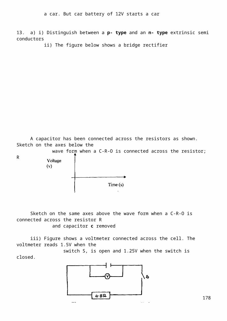
(c) Make LN and MN and record your values in the table 2 below
Angle of incidence LN(mm) MN (mm) Refractive index LN MN
15o
30o
45o
(d) Average value of refractive index = ______________
Question 2You are provided with the following apparatus: Bi convex lens Lens holder Screen S Candle Screen with cross wire X Meter rule Plasticine
Proceed follows:-(a) Arrange the apparatus as shown in the diagram below:-‘
(Ensure the metre rule is firmly held on the bench by plasticine and the flame and crosswire is at a horizontal level with the centre of the lens throughout the experiment)
(b) At a point a = 94cm from the screen X, obtain a sharp image of the crosswire on screen S by adjusting the position of the lens along the metre rule. Record the values of b and c as shown in the diagram.(c) Adjust the position of screen S along the metre rule for a =90cm, obtain a sharp image of the crosswire on screen S by adjusting the position of the lens. Record the corresponding values
178
N
L
15o
O
Fig. 4 N
M
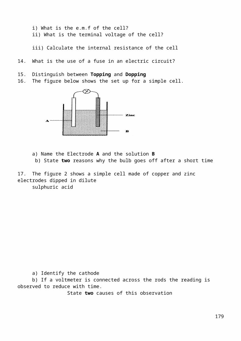
of b and c
Repeat the procedure (a) and (b) above for other values of a = 94cm, 90cm, 86cm, 82cm, 78cm, 74cm and complete the table below
a cm b cm C cm d = a/c
949086827874
(d) Plot a graph of b(cm) (y-axis) against d (e) Determine the slope S of the graph
(f) Given that the equation of the graph is determine the value of L from the equation above
(g) What does L represent ?
PART IIArrange the apparatus as shown below:
(a) Obtain a sharp image of flame on screen S by adjusting the position of screen S. Record the image distance , V = _________cm (b) Determine the constant m = V u(c) What does m represent?
NDHIWA DISTRICT
Question 1
179
b =(100)d L

You are provided with the following apparatus:- A metre rule A wire of length at least 100cm A retort stand, boss and clamp A stop watch or stop clock A micrometer screw gauge An overflow can, a beaker atleast 50ml A 50ml measuring cylinder A piece of thread about 30cm Water in a 250ml beaker Two pieces of wood Mass labeled m
Proceed as follows:- (a) (i) Fill the overflow can with water to overflowing level and then allow it to drain.
(ii) Immerse the mass m into the can. Collect the overflow in a beaker as shown below in fig 1:-
fig. 1
(iii) Using the measuring cylinder provided determine the volume V of the water collected in the beaker V = _____________________________ cm3
(iv) Calculate I given that I = 10 6 m V where m = 0.30kg(b) Set-up the apparatus as shown in figure 2 below. Ensure that the wire is free of kinks and the end
tied to the hook is firm and the hook does not move.
fig. 2
(c) Adjust the length L, of the wire so that L = 70cm, Give the mass m, a slight twist such that when released it oscillates about the vertical axis as shown by the arrows in figure 2 measure the time for twenty oscillations and record in table 1.
(d) Repeat the procedure in (c) above for other values of L shown in table 1. Complete the table180
Wire
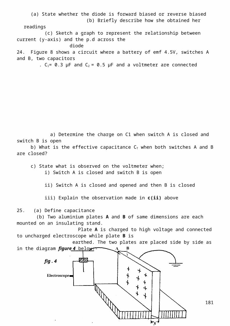
Table 1:Length L(cm) 70 60 50 40 30 20Length L (m)Time for 20 oscillations (s)Period T (s)T2(s)2
(e) On the grid provided, plot the graph of T2(S2) against L (m) (f) Measure the diameter d of the wire d = ....................metres (g) (i) Determine the slope of the graph
(ii) Given that T2 = 32 p 2 L where G is a constant, use the graph to determine the value of G Gd
Question 2. You are provided with the following apparatus:-
- Two new dry cells- A resistor labelled Q- A wire AB mounted on a millimeter scale- 6 connecting wires with crocodile clips on one end of atleast three- A voltmeter- An ammeter- A switch
Proceed as follows:-(a) Connect the apparatus provided as shown in figure 3 below:-(b)
fig. 3
(i) Take the voltmeter reading when the switch S is open.V1= ........................Volts (ii) Close the switch S, and take the voltmeter reading V2 and the ammeter reading I
V2 = ....................................VoltsI= ........................................Amperes
(iii) Calculate the quantity P = V1 – V2 I
(c) Set-up the circuit as shown in figure 4:-
181

fig. 4
(i) Take the voltmeter reading V and the ammeter reading I (ii) Determine the resistance R of Q given that R = V I N/B :-The circuit must be left open when no reading is taken (c) Set-up the circuit shown in figure 5
fig.5
(d) Move the crocodile clip along the wire AB to a point such that L = 100cm. Note the voltmeter reading and record in table 2. (e) Repeat (d) above for values of L= 80cm, 60cm, 40cm, 20cm and 0cm, tabulate your results
Table 2Length L (cm) 100 80 60 40 20 01 1L cmVoltmeter reading (V) I (1/V)V
(f) Plot the graph of I against I V L
(g) Find the slope of the graph
MUMIAS DISTRICT1. You are provided with the following apparatus:
- Ammeter (0-2.5A)- A voltmeter (0 –5 V)- A straight wire AB 1.0m long mounted on a millimeter scale- Two jockeys- Connecting wires- Micrometer screw gauge (to be shared)- Two dry cells (size D) a cell holder and a switch- A cell holder- Switch
Procedure:(a) Using the micrometer screw gauge, determine the diameter d of the wire
Set up the apparatus as shown in fig. 1
182

Fig. 1
With both jockeys set at L=10cm from A, measure the current I through the wire and voltage (V) across. Repeat these corresponding values of current I and voltage (V) in the table below:
Length (cm) 10 20 30 40 50 60 70 80 90 100Length (m)Current I(A)Voltage V(V)R = V/I (W)
(i) Using the values in table I plot a graph of Resistance R(W) against length L(m) (i) Determine the slope of the graph (ii) Determine the resistivity of the material of the wire given that; R = 4ρh pd2
2. You are provided with the following apparatus:
- A spring balance, (0-2.5N)- A retort stand, a boss and a clamp- A wooden block- One 50g mass- A beaker and some water- Five pieces of strings- A vernier calipers (to be shared)
Procedure(a) Measure the length of the wooden block using a vernier calipers L = (b) From the lower end of the wooden block, mark levels on the wood at intervals of 1cm for 5cm as shown. Mark these levels using pieces of thread(c) Set-up apparatus as shown below in fig 2.
183

Fig. 2
(d) Lower the mass into the empty beaker provided. The mass should be as low as possible by not touching the base of the beaker.
Record the reading W1 of the spring balance (i) Slowly pour water into the beaker until the mass is completely immersed. Continue adding
Water into the beaker until when the level reaches mark (thread) indicating 1cm on the wooden block. Read and record the value W2 of the spring balance (Don’t disturb the wood and mass when pouring water into the beaker)
(e) Repeat procedures in d(ii) above by adding water up to the line indicating 2cm, 3cm, 4cm and 5cm. Denote these lines by values h. Complete the table for different values of h
h(cm) 1 2 3 4 5W2 (N)F= (W1 – W2) (N)
f. (i) Plot a graph of F against h (ii) Determine the gradient of the graph (iii) Given that F =Dgh + C Whereby D and C are constants, g = 10N/kg 100 use the graph to determine the values of D and C d
(iv) Determine the constant W for the wooden block given that W = DL
KISUMU WEST DISTRICTQuestion 1
- You are provided with the following:- - A voltmeter- An ammeter- Two dry cells and a cell-holder- A switch- A potentiometer or Rheostat- Six connecting wires
Proceed as follows:-(a) Set-up the circuit as shown in figure 1 below:-
184

fig. 1
(b) With the switch open, record the reading Eo of the voltmeter Eo= ……………………….............................................................volts
(c) Close the switch. Adjust the voltmeter to read 0.5volts using the potentiometer or Rheostat. Measure the corresponding current with the ammeter and record in table 1(d) Repeat the procedure in (c) using different voltmeter readings provided in tale 1 below, each time recording the corresponding ammeter reading. Complete the table
Table 1
Voltage (V) Volts 0.5 1.0 1.5 2.0 2.5
Current (I) A
I (A-1)I
R = V (Ohms)I
(e) Plot a graph of 1/I (y-axis ) against R(f) Determine the slope S of the graph(g) (i) Find Ro, the value of R when1/I = 0 A-1
(ii) Evaluate 1/S – Eo
Question 2.You are provided with the following apparatus:
- A thin lens marked L- A lens holder- An office pin- An optical pin- A white screen- A metre rule- Some plasticine
Proceed as follows:- (a) Set-up the apparatus as in figure 3 below
185
Rays from distant ob-ject e.g. window
Focus a distant object, say a window, by letting the lens L position invariant. Meanwhile slide the white screen back and forth till a sharp image of the distant object; window, appears clearly on the white screen. Measure the distance, f, between the lens L and the white screen f = ………………………….cm
(b) Set-up the apparatus as shown in figure 4 below. Use the office pin as an object and place it at a distance less than f; of the lens L. Mount the office pin on plasticine to enhance its proper visibility through the lens L Take the optical pin and use it as a search pin. Find a position of no parallax between the search pin and the image through the lens L. Measure the distance between the office pin and the image, V in centimeters
(c) Describe the image characteristics (d) Put the object pin near the lens L, that is, at u = 3cm. Observe through the lens L such that there is no –parallax between the object and the image, i.e. when V= 3cm (e) Repeat the procedure using at least six different values of u. complete table 2 below:-
Table 2:
Object distance, Ucm 3.0 4.0 6.0 7.0 8.0 10.0 11.0 12.0
Image distance , Vcm
M = V U
186
fig 4
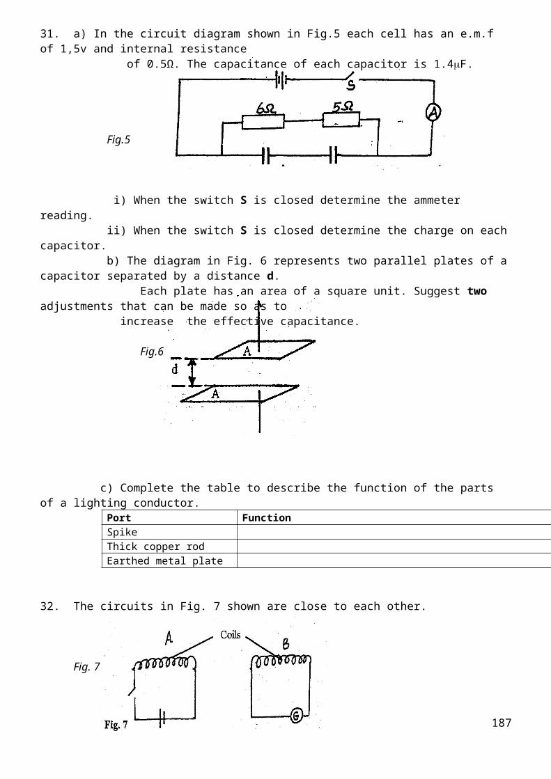
(f) Plot a graph of U (y-axis) against V (g) (i) from your graph, find the value of V when u » f (ii) State the application of this practical in real life experience
TRANS- NZOIA WEST DISTRICT
PART A 1. You are provided with the following:
- A complete retort stand- An optical pin- A concave mirror and a holder or a lump of plasticine- A cork- A candle- A screen- A metre rule
You are required to estimate the focal length of the mirror. Arrange the apparatus as follows in figure 1 below:Figure 1
a) By adjusting the clamp on the stand, move the object pin up and down until the inverted image and pin itself appear to coincide (use – no- parallax method). Measure the distance
h = …………………………………… cmb) Calculate the value f given that
f= h/2 -----------------------------c) Arrange the apparatus as shown in figure 2 below
Figure 2
187
Eye Cork
Stand Image
Object pin
h
Mirror
Screen Candle Image
u
V

d) Place the candle at a distance u = 22cm from the mirror. Move the screen along the mirror rule until a sharp image is formed on the screen. Measure and record the image distance V
e) Repeat the experiment with the values of u = 24cm, 26cm, 28cm and 30cm. Record your values in table 1 below
Object distance u (cm) Image distance V (cm) Magnification M= v/u2224262830
f) Plot a graph of magnification, m (y- axis) against image distance, vg) Given that M = V - 1 . Determine the focal length, f f
PART BYou are provided with the following apparatus:-
- A lens- A lens holder- A white screen- A metre rule- Candle
Procedurei) Set up the apparatus as shown in figure 3 below
Figure 3
j) Starting with u = 30cm adjust the position of the screen to obtain a sharp image of the candle. Record the value of V in the table 2 below
k) Repeat the procedure above for u = 20 cm and complete the table 2 belowTable 2
(U) cm V (cm) Uv (cm2) U+V (cm)2030
ii) Given that the focal length of the lens satisfies the equation, f = UVU+V
Determine the average value of the focal length f
Q2. You are provided with the following:
188
Lens Candle
Screen
Vu
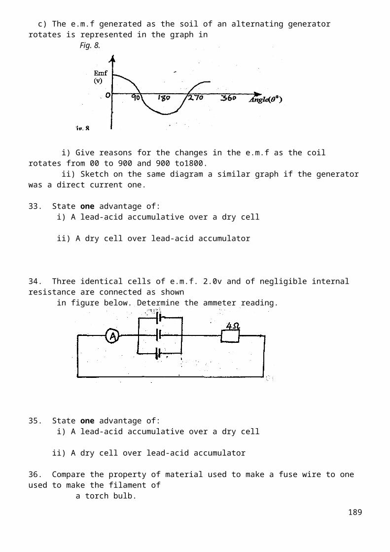
- 2 dry cells- A cell holder- A torch bulb- A bulb holder- A voltmeter- An ammeter- A switch- 8 connecting wires, one with a jockey and some with crocodile clips- A wire attached on a metre rule or millimeter scale
Proceed as follows :-a) i) Set up the circuit as shown in figure 4 below
Figure 4
ii) With the jockey at P (i.e. L= 100 cm), take the voltmeter reading (v) and ammeter reading (A) Record V and I readings in table 3 below
iii) Repeat the procedure to take readings for L = 80 cm, 60cm, 20cm and 0 cm respectively Record your readings in table 3 below:Table 3
L (cm) 100 80 60 40 20 0V (v)I (A)
iv) What changes do you observe on the bulb as Ll decreases from P to Q ? v) Plot a graph of voltage (v) (y- axis) against current (I) vi) Determine the slope of graph when I = 0.226A vii) What physical quantity is represented by the slope of the graph at any given point? viii) Use your graph to describe how the physical quantity in (vii) above is affected as current increases. Explain
b) Using some of the apparatus in a (i) above, draw a diagram you would use to determine resistance of the wire. Explain how you determine the resistance
RACHUONYO SOUTH DISTRICT
1. You are provided with the following:- Ammeter A voltmeter A straight wire XY mounted on a millimeter scale Two jockeys 7 connecting wires A micrometer screw gauge (to be shared)
189
S
Jockey Millimeter scale
P Q
100cm
A cell holder for two dry cells Two dry cells A switch
Proceed as follows:(a) Using the micrometer screw gauge, determine the diameter ‘d’ of the wire XY
d = ________________________mm Set-up the apparatus as shown below:-
With both jockeys set at L = 10cm from X, measure current I through the wire and voltage
V across it. Repeat this procedure for the other values of L and record in the table below:Length (cm) 10 30 40 50 70 80 100Length (m)Current I(A)Voltage V(V)R = V/I(W)
(b) (i) Using the values in the table above, plot a graph of I(A) against R(W) on the grid provided (ii) Determine the gradient of the graph at R = 10W (iii) Given that -I = π d 2 R where L = 60cm, find the value of K 4KL
2. You are provided with a glass vessel of a minimum height of 12cm and a minimum diameter of 6cm, a retort stand and clamp, two optical pins labelled A and B, liquid M, ½metre rule and a cork:
ProcedurePlace a pin A at the bottom of the glass vessel and then pour liquid M upto a height of 2cm from the bottom of the glass vessel. Move pin B on a sliding cork adjacent to the jar up or down until there is no parallax between it and the image of pin A. mark on the outside of the beaker where the image pin is located
(a) Measure X and record its value X = ____________________________ cmmk)
(Note that Xis the distance between top level of liquid M and where the image of pin is located)(b) Repeat this procedure for different values of y from the initial value of 2cm in steps of 2cm.
complete the table shown below:Ycm 2 4 6 8 10 12
190
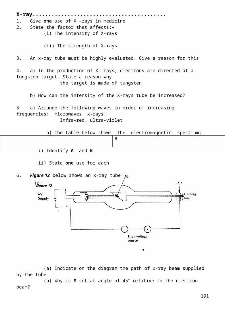
X cmArrangement of apparatus
(c)Draw a graph of x (y-axis) versus y on the grid provided (d) Calculate the slope, S of your graph
(e) Given that n = 1 , calculate the value of n s
B. You are provided with the following: A half metre rule Two pieces of thread 50g mass A retort stand, clamp and boss
Proceed follows(i) Using a loop of thread suspend the half metre rule on the retort stand as shown below, at 41cm(ii) Using the second loop suspend the 50g mass at a point that sets the half metre rule in equilib-
rium, as shown below. (Horizontally balanced)
Record the value of 191
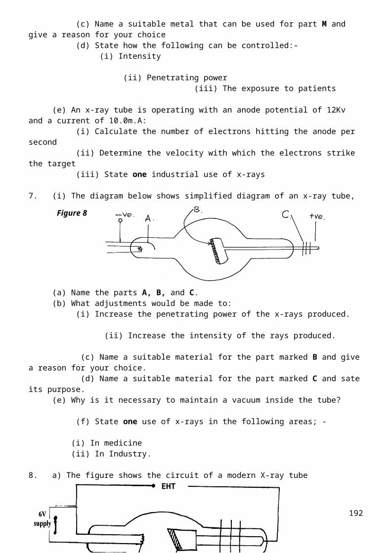
P = ……………………………………..cm Using the equation; M x q = P x 50, calculate the value of M N/B q + 25 = 41
SOTIK DISTRICT 1ST EXAM
1. You are provided with the following apparatus:- Full retort stand Optical pin 20cm copper wire Protractor Two pieces of plasticine Cork Stop watch *
A. Bend a wire in the middle. Place it on a protractor and adjust an angle q of 50o. Attach the two pieces of plasticine on the ends of the wire. Then place the wire on the optical pin as shownB. Displace the wire horizontally by a small angle and set it in oscillation. By use of stop watch
obtain time for 20 oscillations. Repeat this procedure for values of q, 60o, 70o, 80o, 90o and 100o. Record your measurements in the table and complete it determining values of period T, frequency ¦(Hz), ¦2 (Hz)2 and cos (q/2)
C. (i) Draw graph of ¦2 (Hz)2 against cos(q/2)C. (ii) Determine the gradient of the graph
C (iii) The relationship between¦and q is 4pL¦2 =150Z cos(q/2) – 10. Where L is 0.2m. Determine the constant Z by the graph
Question 2PART AYou are provided with;- 1000ml measuring cylinder , Clean water, Two optical pins, Retort stand, Cork, and a Wooden block
192
Optical pin
Copper wire qClamp Cork
Plasticine Retort stand
Retort stand
Angle q o Time t for 20 oscil-lations in sec
Period T(Sec)
Frequency ¦ (Hz)
¦2 (Hz)2
cos(q/2)
5060708090100
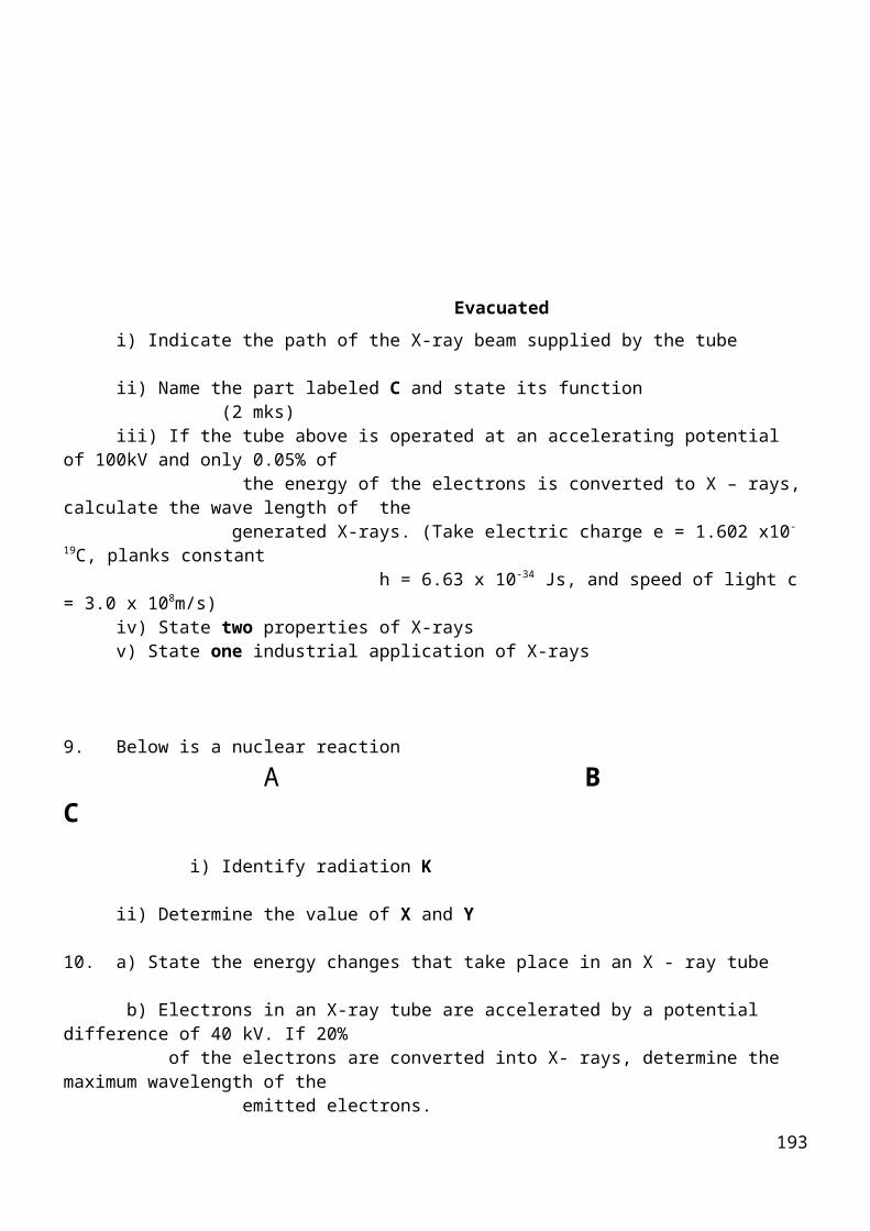
A. Place optical pin in the measuring cylinder. Add water to reach 400cm3 mark. View the optical pin through water and locate its image. B. (i) Place another optical pin in cork and then in retort stand clap as shown. Move this optical pin (search pin) up and down until it coincides with image optical pin as seen through water. Read off the volume reading of the search optical pin when it coincides with image of object optical pin. Repeat this procedure for water volume marks of 600, 700,800, 900, and 1000cm3. Enter your observations in table *
TableWater level volume reading H cm3 Image level volume reading h cm3
4006007008009001000
B (ii) Draw a graph of H(cm3 ) against h(cm3)C (i) Determine slope of your graph
(ii) Determine M if H = mh + C where M and C are constants (iii) If m = M where M is refractive index of water, determine M
M-1
Part BYou are provided with a lens, plane mirror, retort stand, cork and optical pin and half metre rule. Set up apparatus as shown
193
Retort stand

Move the object optical pin up and down. Look for its image. When object optical pin coincides with its image measure the vertical distance from mirror to object optical pin. Repeat the experiment.(i) 1st attempt: Vertical height of optical pin = __________cm
2nd attempt: Vertical height of optical thumb pin =______________________cm (ii) Determine the average vertical height of optical thumb pin (iii) Now determine the focal length of the lens using the above measurements
SOTIK DISTRICT 2ND EXAMQUESTION 1Part AYou are provided with the following: A uniform metre rule. A spring balance. Two 15 cm long string. 2 complete stands. 30 cm or half metre rule. A set square.
Proceed as follows:a) Set the apparatus has been set ready for use as shown in the figure below. The metre rule has suspended at the 99.0 cm mark with a length of string securely tied to the clamp of the retort stand Q.
194

So not change this position throughout the experiment.
b) Adjust the position of the clamp of the retort stand P so that the metre rule is suspended at 0.5 cm mark and is horizontal.c) Note and record the distance, x from A to B and also the tension, T, of the spring balance.
Enter your results in the table below.x (cm) T (N) 1 (m-1)
x
(3 mks)d) Adjust the position of the clamp of the retort stand O so that the metre rule is suspended at the 10.0 cm mark and is horizontal. Note and record the distance x and T in the above table.e) Repeat part (d) of the experiment with the spring balance suspended at the 15, 20, 25 and 30 cm marks. Enter your results in the table and complete the table.f) (i) On the grid provided, plot a graph of T (y –axis) against 1 (5 mks)
(ii) Determine the slope, S, of the graph. (2 mks) (iii) Given that M = S , find a value M, the mass of the metre rule (1 mk)
4.8B. a) (i) Place a candle and screen about 50 cm apart. Place a lens (convex) in between the screen and the candle. Move the lens from about 10 cm from the candle towards the
screen until a sharp image is focused on the screen. Mark this point U1. Move the lens until the second sharp image of a smaller size is focused on the screen. Mark this point U2.
(ii) Measure the displacement of the lens i.e. distance between U1 and U2 and let it be X1. Let the distance between the screen and the candle be Y1 i.e. Y = 50 cm.(iii) Repeat the procedure in (a) above by using a value of Y of 40 cm. Let it by Y2. Find the displacement X2
Find the value of x = x1 + x2, and value of Y = Y1 + Y2. (2 mks)
195

2(iv) Given the equation 4f = X2 – Y2
Y Calculate the focal length of the lens(f). (3 mks)
2. You are provided with the following apparatus. Two cells of 1.5v each, Nichrome wire gauge 30. An ammeter 0-5 A or 0-25 A range, cell holder, voltmeter 0.3v or 0.5 eight conductors at least 4 with crocodile clips,, A switch and a metre rule.Procedure(a) Connect the circuit as shown in the diagram below.
(b) (i) Connect the ends A and point C where AC is 100 cm across the terminal as shown. Close the switch and measure both current I and p.d. across the wire AC. Current I = (1 mk) p.d.(v) = (1 mk) (ii) Measure the e.m.f. of the cells E = (1 mk)
(c) Reduce the length AC as shown 100, 70 cm, 60 cm, 50 cm, 40 cm and 20 cm. In each case record the current (I) and the corresponding p.d.(v)(d) Enter the length in table.
Length L (cm) 100 70 60 50 40 20I (A)V (Volts)E – V (V)
Complete the table (6 mks)(e) (i) Plot a graph of (E-V) (V) on the y –axis against I(A) on the x – axis. (5 mks) (ii) Determine the gradient of the graph. (3 mks) (iii) Given the equation E + V + Fr determine the internal resistance of each cell. (3 mks)
TRANS MARA DISTRICT1. You are provided with the following:- *
Dry cell, An ammeter (0.25A) A voltmeter (0-2.5V) A mounted resistance wire, 6 connecting wires A jockey or a crocodile clipProceed as follows:-
(a) Set up the experiment as shown in the figure below:-
196
Jockey

(b) With the jockey at X, record the ammeter and voltmeter reading (c) Vary the length of the mounted wire through which current flows by moving away from X to a new point Y. record the ammeter and voltmeter readings obtained in the table below.
Length (cm) 0.0 0.1 0.2 0.3 0.4 0.5 0.6 0.7 0.8Volmetre read-ings (v)Ammeter read-ings (A)
(d) On the grid provided plot a graph of V (y axis) against I (e) Determine the slope, M of the graph(f) The equation of the cell from which current is being drawn is E = V + Ir Use the equation to determine:- (i) E.m.f of the cell (ii) The internal resistance of the cell
2. You are provided with the following:- A candle a metre rule A white screen A lens and a lens holder Cross wires mounted on a cardboard Plasticine
Procedure:- (a) Place a metre rule on a bench and hold it in position using plasticine Arrange the screen, the lens and the cross wires along the metre rule as shown:
(b) Light the candle and place it next to the cross wires such that the flame is at the same level with cross wires and the cross wires concide with the middle part of the flame. (c) Adjust the position of the lens so that U=15cm. Now adjust the position of screen until a sharply focused image of cross wire is obtained in the screen. Record the value of V in the table(d) Repeat the procedure in (c) above for values of U shown in the table
197
(e) Plot a graph of (U + V) against V
(f) From the graph determine the values of V and (U+V) for which the graph has minimum values V minimum Vm = ___________cm (U+V) minimum (U + V)m= __________cm(g) Calculate the values of h1 and h2 from the equations below (i) h1 = Vm = ________cm 2 h2 = (U+V)m = cm ___________ 4 (ii) Determine the average of h1 and h2
h = h1 + h2 = ____cm 2(h) Using the graph, determine V when U + V = 41.6cm
SECTION III – ANSWERS
KAKAMEGA CENTRAL DISTRICT1. c)i) Repeat the procedure in (b) above for the values of d shown in the table (set the values of d by adjusting the positions of the loops in steps of 5cm on both sides)
ii) Complete the tableD (cm) D (m) 1 (M-2)
d2 Time for 10 oscillations ± 0.50 S
Period T (s) T2 (S2)
80 0.80 1.5625 5.91 0.591 0.349370 0.70 2.04082 7.66 0.766 0.586860 0.60 2.778 8.65 0.865 0.748250 0.50 4.000 10.44 1.044 1.089940 0.40 6.2500 12.88 1.288 1.658930 0.30 11.1111 16.94 1.694 2.869620 0.20 25.000 25.41 2.541 6.4567
d ) i) On the grid provided, plot a graph of T2 (y – axis) against 1/d2 (M-2) ii) Determine the slope of your graph
Slope = (250 -0) X 10 -2 S2 S = 2.5 X 10 -1 M2 S2
(100 -0) X 10 -1 M -2 S= 0.25 M2S2
iii) Given that T2 = 16K 2 where K is a constant. Use the graph to determine the value of 5d2
16K2 = slope K = 0.25 X 5 M 2 S 2 5 16K2 = S X5 K = 0.2795
16
QUESTION 2 c) Measure the distance, d, between the two parallel wire that acts as the object d =1.50 cm
198
U(cm) V(cm) (U + V)cm1517192123252729

Record this value in the table below.g) Repeat your readings of x with u = 70, 60, 50, 40 and 30cm and complete the table (5 marks)
i) On the grid provided plot a graph of u (y – axis) against d/xii) I . Determine the slope, S of the graph S = 85 -40 S = 45 275 -80 X 10-2 195 X10-2
= 23.076 cmII. Find the intercept on the u – axis U – intercept = 20.0 cm PART Biii) Repeat procedure (i) and (ii) above with XJ = 20 cm and enter in the table 3as below
Table 3Length XJ (cm) P.d.V . (v) Current, I (A)10 1.1 0.4520 1.5 0.25
J) Given that log I = n log V + log K, where k and n are constants, determine the values of k and n
log(0.45) = n log (1.1) + logk -0.03468 = 0.0414nlog(0.25) = n log (1.5) + logk -0.6021 = 0.1761n 0.2553 = -0.13469n n= 1.8955 T. 6532 0.414 n = 0.2553 - T.3979 = 0.1761 n -0.1347 0.2553 T.8653 n = -1.8955
log(0.45) = -1.8955 log(1.1) + log klog k = log (0.45) + 1.8955 log (1.1)= T .6532 + 1.8955X0.0414= T.6532 + 0.0785 log = T.7317 T .7317
K = 0.53913.
KAKAMEGA EAST DISTRICTXcm X1 C(cm) X2 (cm) X1 – X2 (cm)454035302520
22.520.017.515.012.510.5
19.2517.7515.3513.1011.009.50
3.252.252.202.001.251.00
½ mk each Max mk – 3At least 1 d.p
½ each 1.0Max mk -3At least - 1d.p
Correct subtraction from candidates’ results5-6 correct -1mk3-4 correct – ½mk<3correct - 0
(c) (i) Graph : Labelled axes with units............................1mk: Simple and uniform scale .........................1mk: Plotting (4 correctly plotted pts .......... ½mk max 2mk: Line (through any 3 of 4 correctly plotted)...1mk
199
U (cm) 80 70 60 50 40 30X(cm) 0.5 0.7 0.9 1.2 1.8 3.2d/ x 3 2.143 1.667 1.250 0.833 0.469

.................Total 5mks)
question 2(a) (ii)
L(cm) 100 80 60 40 20 0P.d, V(volts) 0.13 0.15 0.20 0.25 0.45 0.70 ±0.02
½ mk each max 3mks atleast 1d.pCurrent, I(A) 0.07 0.10 0.11 0.13 0.15 0.17 ±0.02
½ mk each max 3mks atleast 1d.p(b) (i) Axes – labelled with units ... . 1mk
Scale – simple and uniform .... 1mkPlotting – 5-6 correctly plotted .....2mks
3-4 – correctly plotted ..1mk < 3 correctly plotted .......0mk total 5mks (ii) Gradient S = DV DI (52 – 25) x 10-2V (16 – 14) = 13.0W ± 2(iii) Resistance............1mk
(c) (i)
(ii) Gradient S (c) (ii) I = 0.09 A ±0.01 ........... ½ mk
200
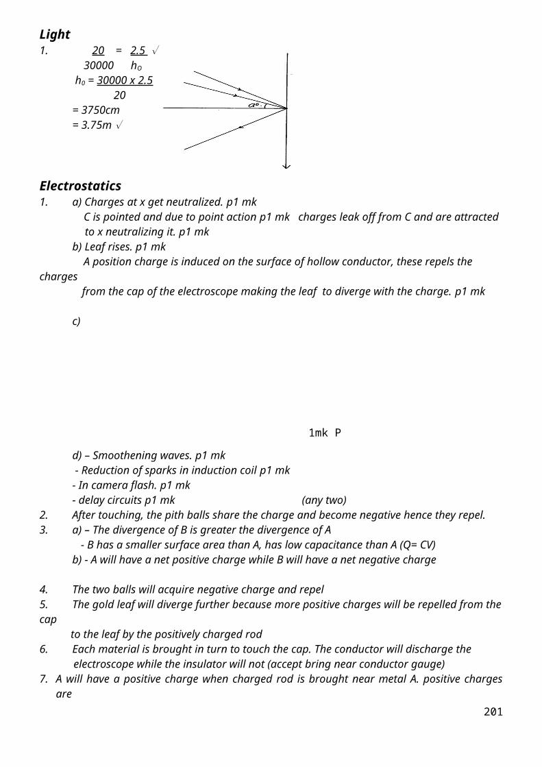
V = 0.80V ±0.01 ½ mk (iii) d = 0.4 0.02mm ......1mk (iv) S =3.142 x 0.80 x (4.4 x 10 -1 ) 2 4 x 0.09 x 100 Answer either in Wm or Wcm
MIGORI/NYATIKE DISTRICT1. (a) (i) h = 5.0cm
(ii) R= 100 h = 100 5
= 4.47cm(b) (iv)
U 3R 4R 5R 6R 7R 8R 9R 10RU(cm) 13.40 17.90 22.40 26.80 31.30 35.80 40.2 44.70V(cm) 21.0 15.0 14.0 12.5 12.0 11.5 11.0 10.5Consistency in values (c) graph plotting
3 and 4 points 5-8 points scalecurveaxis
(d) (i) V1 = 17.5cm (ii) U1 = 2.26.25Give reading off from the graph *UGU* each(e) f = U 1 + V 1 5 = 17.5 + 27.5 5 = 45 = 9cm 5
(f) R = 4.47 f 9 = 0.496667 = 0.50 (total 20mks)2. Part A
(d) Time t (min) 0 1 2 3 4 5 6 7 8Temperature (oC) 80.0 77.0 74.0 71.0 68.5 66.5 64.0 62.0 60.5
(i) trenddecimal place acquiredfilling the table(ii) Plotting P2 scale S Axis A curve C(iii) Tangent line drawn at 70oC and identifying two points (5,66 and (1,45, 74) d q = 74- 66 dt 1.45 – 5 = 8
-3.15 = -2.540
201
P1P1 P1
P1
P1
P1P1P1P1
P2
C1S1
A1P2
P2
P1
P1
P1
P1
P1P1
P2P1
P1P1P1
P1
P1
P1
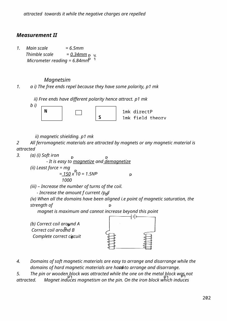
(iv) Heat loss, R = K d q dt = 1.23 x 104 x 2.540 = 31,242J
SOTIK DISTRICT1. (i) d = 0.635cm 0.05
(ii) V = 4/3 (0.635)3 = 0.134cm3 0.13 allow 0.14(iii) d = 1.68 0.01(iv) A = r2 = 3.14 x (1.68)2 = 2.21 (2.21 - 2.30)
=(b) (iii) ho = 8.6cm ±0.2cm 8.0(d)
N h h-ho
1 9.0 0.42 9.7 1.13 10.3 1.74 10.9 2.35 11.5 2.96 12.0 3.4
(1mk for mark for each h value upto a max. of 4mks )1mk for atleast 5 correct differences½ mk for 3 and 4 correct differences
2 or less correct differences 0mks
(e) Axes – must be labeled the units (mark both) Scale – be simple & uniform * Plotting = ½ mk for each correctly plotted points up to 2mks > 4 correct plotted 2mks > 2 & 3 correctly plotted 1mk <2 correctly plotted 0mk Line must pass at least 3 correctly plotted points (f) S = 0.527cm – Identifying the pts on the graph
-Correct substitution ( ½ mk)-Correct answer to 2d.p ( ½ mk)
(g) Os = 0.527 x 2.21 (correct sub 0.134 = 8.69 ( no units) (correct evaluation to 2d.p –
2. PART 1(c)
i 10o 20o 30o 40o 50o 60o
r 8o 13o 18o 24o 30o 36o ±1o
d 0.5 0.9 1.3 1.9 2.8 3.2 ±0.1cm½ mk for each correct value of both r and d(d) Axes (Quantity and units- 1mk) Scale (simple and uniform 1mk) Plotting ( ½ mk for each correctly plotted point up to 2mks) The graph’s curve as shown Maximum = 6mks Smooth curve with correct shape as shown 1mkNote:- The workings on the plain paper must be seen before marking this section
202
P1P1

2. Part II(b) i1 = 30cm, V1 = 0.75 ± 0.05 i2 = 50cm, V2 = 1.225 i3 = 70cm , V3 = 1.75
(d) i1 = 30cm , I = 0.12A ± 0.01 i2 = 50cm i2 = 0.16A i3 = 70cm F3 = 0.20A*STK*
e(i) V1 = 30 x 0.0025 = 0.75V V2 = 50 x 0.025 = 1.25V V3 = 70 x 0.025 = 1.753values of V correctly calculated 1mk2 values of V correctly calculated ½ mk0.01 value of V correctly calculated 0mk
(ii) R1 = V1 = 0.75 = 6.25W I1 0.12 R2 = V2 = 1.25 = 7.81W I2 0.16R3 = V3 = 1.75 = 8.75W I3 0.2
3 values correctly calculated to 2d.p 1mk2 values correctly calculated to 2d.p ½ mk0 or 1 value correctly calculated to 2d.p 1mk 0mkAverage R = R1 + R2 + R3 = 6.25 + 7.85 + 8.75 = 22.85 = 7.617W 3 3 3Substitution of 3 values of R ½ mkCorrect evlauation of average R value to 3d.p ½ mk
UGENYA/UGUNJA1. (d )
(a) Repeat the procedure above for the other given angles on table 1
(f) Gradient of Dy = (2.4475 – 1.75) Hz2
Dx (0.96 -0.68)= 0.725 Hz 2
0.28 = 2.589Hz2
(c) (i) f = 10 = 10 t 6.28 = 1.592Hz
PART B(c)
Angle of incidence LN(mm) MN (mm) Refractive index LN/MN
15o 13 7 1.857203
Angle q o Time( t)for 10 oscillations ¦ = 10/t ¦2 (Hz)2
q/2 Cos (q/2)
20 6.28 1.592 2.54 10 0.9940 6.47 1.546 2.39 20 0.9460 6.63 1.508 2.28 60 0.8780 7.28 1.374 1.89 40 0.77
100 7.87 1.271 1.62 50 0.64
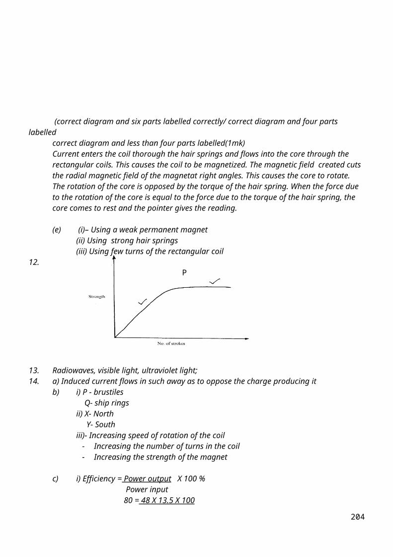
30o
45o2536
17.524
1.4291.500
(d) Average = 1.875 + 1.429 + 1.500 3 = 1.60 (2 dp) Results of question 2
a cm b cm c cm d = a/c
94 67 27 3.48190 62 28 3.21486 56 30 2.86782 50 32 2.56378 42 36 2.16774 37 37 2.00
Trend 2 d=1Correct = 3 4 correct = 2
total 06mks(d) graph A 2 S1 P3 L1 = 7mks)(e) Slope Db = 2.5cm
Dd 1.3 S = 19.23cm(f) L = 100
5= 100 19.23 = 5.2Dioptres (5.0 ± 0.2) (g) Power of the lens
NDHIWA DISTRICT
1. (a) (iii) V = 45cm3
(iv) I = 106 x 0.30 for substitution 45 = 6,666.7kg/m3
(d) Length L(cm) 70 60 50 40 30 20Length L (m) 0.70 0.60 0.50 0.40 0.30 0.20Time for 20 oscillations (s) 61.01 56.08 51.36 46.006 39.81 32.80Period T (s) 3.057 2.804 2.568 2.303 1.991 1.640T2(s)2 9.309 7.862 6.595 5.304 3.960 2.690– Correct conversion of length L in m- time for 20oscillations ( ½mk) for each value within range (maximum of 3mks)- correct evaluation of period - correct evaluation of T2
(e) Axes : labelled with units Scale : simple and uniformPlotting : Each correctly plotted( ½mk) to a max of 2mks)line – passing through at least 3points correctly plotted.
(f) d = 0.34 x 10-3
= 3.4 x 10⁻⁴m(g) (i) DT2 = 8.6 – 2.0 DL 65 – 15 6.6 = 0.1320 50(ii) T2 = 32 p 2 L Gd
Gradient = 32 p 2 Gd
G = 322 x (3.14) 2 3.4 x 10-4 x 0.132
204
De-creas-ing trend
Increas-ing trend
P
P
PPPP
PPPP
P
P

= 7.03898 x 10⁻⁷
Q2. (a) (i) V1 = 3V (ii) V2 = 2.80V I = 0.24A
(ii) P = 3.0 – 2.8 0.2 = 1W
(b) (i) V = 2.5V I = 0.25A R = 2.5 0.25 = 10W
Length L (cm) 100 80 60 40 20 01 (1L cm
0.01 0.0125 0.0167 0.025 0.05 µ
Voltmeter reading (v) 1.8 1.3 1.1 0.9 0.6 00I (1/v)V
0.667 0.769 0.909 1.111 1.667 µ
MUMIAS DISTRICT
a) diameter d = 0.28mm + 0.02
Length (cm) 10 20 30 40 50 60 70 80 90 100Length (m) 0.1 0.2 0.3 0.4 0.5 0.6 0.7 0.8 0.9 0.1Current I (A) 0.70 0.54 0.44 0.32 0.28 0.26 0.22 0.20 0.18 0.16Voltage V (V) 1.20 1.80 1.80 2.20 2.40 2.50 2.50 2.60 2.70 2.74R= v/I (x) 1.71 3.33 4.09 6.88 8.57 9.62 11.36 11.36 13.00 17.13
b) GRAPHi) Axes- labeled with correct units Scale – simple, uniform, and consistent and accommodate all values Points – 4 correctly plotted points within an error of one small square Line- straight line passing through at least 3 correctly plotted pointsii) Gradient = R/L = 16.4 – 0/1.04 = 15.7692nm-1
iii) R = 4p2/d2
M= 4p/d2
P = md2/4
= 15.7692 X (0.28 X 10 -4 ) 2 4 = 9.7265 X 10⁻⁸ RM
2. a) L = 8.0 cmd) i) 0.80 + 0.2
H(cm) 1 2 3 4 5W2(N) 0.8 0.7 0.6 0.5 0.4F = (W1 – W2)N 0.2 0.30 0.40 0.50 0.60
f) i) LabellingÖAppropriate scaleÖPlotting Ö ÖStraight/ smooth line Ö
ii) M = DF/DH
= 0.6 – 0.2/5-1
= 0.4/4
= 0.1/cmiii) Dg/100 = m
205
P
- Correct conversion ½ - Voltmeter reading ½ each- Correct evaluate 1mk
P

D X 10/100 = 0.1/0.01
= 100Kg/miv) W= 100Kg/m X 0.075m = 7.5 Kg
KISUMU DISTRICT Question 1.(b) Eo = 3.2 ± 0.1 volts
Voltage (V) Volts 0.5 1.0 1.5 2.0 2.5 2.7Current (I) A 0.67 0.48 0.36 0.24 0.12 0.06 ± 0.021 (A-1) I
Candidate’s values correct to 3d.p
R = V (Ohms)I
Candidate’s values correct to 3d.p
(e) graph(f) Slope = 3.0 – 1.50
5.0 – 0= 1.5
5.0= 0.3 A-1W-1
(g) (i) When 1 = 0 , r = Ro = 5Ω ±1 *KSM* I
(ii) 1 – Eo
S
= 1 – 3.2 0.3 = 0.1± 0.01 V
Question 2 (a) f = 20 1cm(c) (i) erect (ii) virtual (iii) magnified
Object Distance, Ucm 3.0 4.0 6.0 7.0 8.0 10.0 11.0 12.0Image distance , Vcm 3.0 5.0 7.8 10.0 13.3 18.5 22.0 29.1 ± 0.2M = V U
Candidates correct values to 1d.p
(f) graph …(g) (i) when u » f, V = Infinitely large number (undefined)
N/B: i.e when object is at F, the image is formed at infinity (ii) Application: Magnifying lens
TRANS NZOIA WEST DISTRICT1. a) h= 30cm
b) f= h/2 = 30/2 = 15 cmc) Table of results
Object distance U cm Image distance V (cm) Magnification M = v/u
22 10.9 0.495524 10.2 0.425026 10.0 0.384628 9.6 0.342930 9.5 0.3167
Accuracy = +- 0.2- For V values award 3 marks for all values within range see accuracy above, otherwise award
½ mark for each correct
206
Peach upto max. 5
Pall values 1mk
total – 8mks
Peach upto max. 7

- For M award 2 marks for all values correct but 3 -4 values correct award 1 mark and less than 3 values correct award 0 marks
- N.B If a school did not use the specified focal length of the mirror it should be indicated so that candidate are not penalized
f) Graph on graph paperAxes (1 mark) - Both quantity and unit on bothScale (1 mark) – Simple and uniformPlotting (2 marks) – All points correctly plotted award 2 marks3 – 4 points correctly plotted (1 mark)Line (1 mark) line to pass in at least three correctly plotted points
NB The line MUST cut the negative part of the Y- axis for a markg) Gradient/ slope = i/f
f = I/slope
= 15 + 0.1 cm
207
PART BTABLE 2 RESULTS
K i)U (cm) V (cm) UV (cm2) U + v cm20 20.0 400.00 40.030 15.5 465.00 45.5ii) f = uv = 400 + 465 = 865 u+v 40 + 45.5 85.5= 10.12cm
2. a) iii) Table of resultsL (cm) 100 80 60 40 20 0V (volts) 1.20 1.35 1.50 1.75 2.00 2.50
0.18 0.20 0.22 0.23 0.24 0.28Award ½ mark for each correct reading See accuracy above
iv) It is brighterv) Graph on graph paper
Scale 1mark (simple and uniform)Plotting 2 marks (each ½ mark max 4 points correctly plotted)Axes 1 mark ( Both quantity and unit on both axes)Curves 1 mark – passing through at least 3 correctly plotted points – No mark
for straight line
vi) Slope – DV = 1.9 – 1.5 = 13.33 DI 0.25 – 0.22
Tangent 1mark (Tangent line must be continuous)
vii) Electrical resistance of the bulbviii) - Resistance increases with increase in current - There is increased resistance to flow of electric current as temperature increases
b)Resistance of wire R = V I
Award for R as shown above or if values have been substituted by the candidate
RACHUONYO SOUTH DISTRICT1. a) d = 0.3mmÖ
Length (m) 0.1 0.3 0.4 0.5 0.7 0.8 1.0I (A) 0.7 0.44 0.36 0.28 0.22 0.19 0.16V/I V(V) 1.2 1.80 2.10 2.40 2.5 2.6 2.74V/I = R (W) 1.17 4.09 5.83 8.57 11.36 13.7 17.13
b) i) Scale S1 Axes A1
Plotting P2 Curve C1
ii) Targent Ö = 0.47 – 0.2 Co-ordinatesÖ 12 - 0 Correct working Ö = 0.0225iii) –I = pRd2
4KLI = pd2R 4KL (Slope at R = 10W) Ö-0.0225 = - p x (0.3 x 10 -3 )2 Ö
4 x K x 0.6K = 3.927 x 10⁻⁴
Wm-1 A-1
208

2. a) x = 1.5cmÖb)
y cm 2 4 6 8 10 12x cm 1.5 3 4.5 6 7.5 9
Ö Ö Ö Ö Ö Öc) A1Ö S1Ö P2Ö Ö L1Ö
d) S = 6 – 4.5Ö 8 – 6 Ö = 0.75 Öe) n = 1.333ÖÖ
P = 8cm ÖM x 16 = 8 x 50Ö
M = 25gÖ
SOTIK DISTRICT 1ST EXAMQuestion 1
Angle q o 50 60 70 80 90 100Time t sec for 20 oscillations
11 12 13 14 16 18 T sec, 1mk for each correct value max 5mks
Period T= t/20 sec 0.55 0.60 0.65 0.7 0.8 0.9 1mk for at least 4cor-rect evaluations
Frequency ¦ = I (H2) T
1.82 1.67 1.58 1.43 1.25 1.11
¦2 (H2)2 3.312 2.789 2.496 2.045 1.563 1.232 1mk for at least 4 cor-rect evaluations
cos(q) 2
0.906 0.867 0.819 0.766 0.707 0.642 1mk for at least 4 cor-rect evaluations
N/B (i) – Period T = t sec should be correctly evaluated to 2 d.p 20 - Frequency should be correctly evaluated to 2 d.p - ¦2 (H2)2 should be correctly evaluated to 3 d.p - Cos(q/2) should be correctly read to 3 d.pC(i) Axes 1mk
Scale (1mk)Simple and uniform
Plotting (2mks)Plot with accuracy of small lines. Each correctly plotted point award ½mk up to max of (2mks)Line (1mk)+ve slope line with negative y-intersect
C (ii) Award gradient mark only when line is correctIntervals (1mk)Substitution 1mkEvaluation 1mk
209
P
P

Gradient = 3.31 – 2.05 = 1.26 = 9 0.91 - 0.77 0.14 (iii) 4pL¦2 = 150Z Cos q/2 – 10
¦2 = 150Z Cos q / 2 – 10 4p L Slope = 150Z 4pL
= 150Z = 9 4pL
Z = 4 p L X 9 150
= 4 22 x 0.2 x 9 7 150
= 0.1509N/B:- Pick point from line substitute in equation and solve for Z
Question 2
Water level volume reading Hcm3 Image level volume reading hcm3
400600700800900
1000
100150175200225250
B. (ii) Axes (1mk)
Scale (1mk)Simple and uniform Plotting (2mks)Correctly plotted point (½mk) for max of 2mks Line 1mkStraight line with + ve gradient passing though at least 3 correctly plotted points
C. (i) Without getting mark for line award (0 marks) for slopeIntervals 1mkEvaluation (1mk)Accuracy 1mk600-400 = 200 = 4 (no units)
150 – 100 50 (ii) M = slope = 4 (1mk) (iii) 4 = M M - 1 4M – 4 = M
3M = 4 ÞM = 4
210
P
P
P
P
PP
P
P
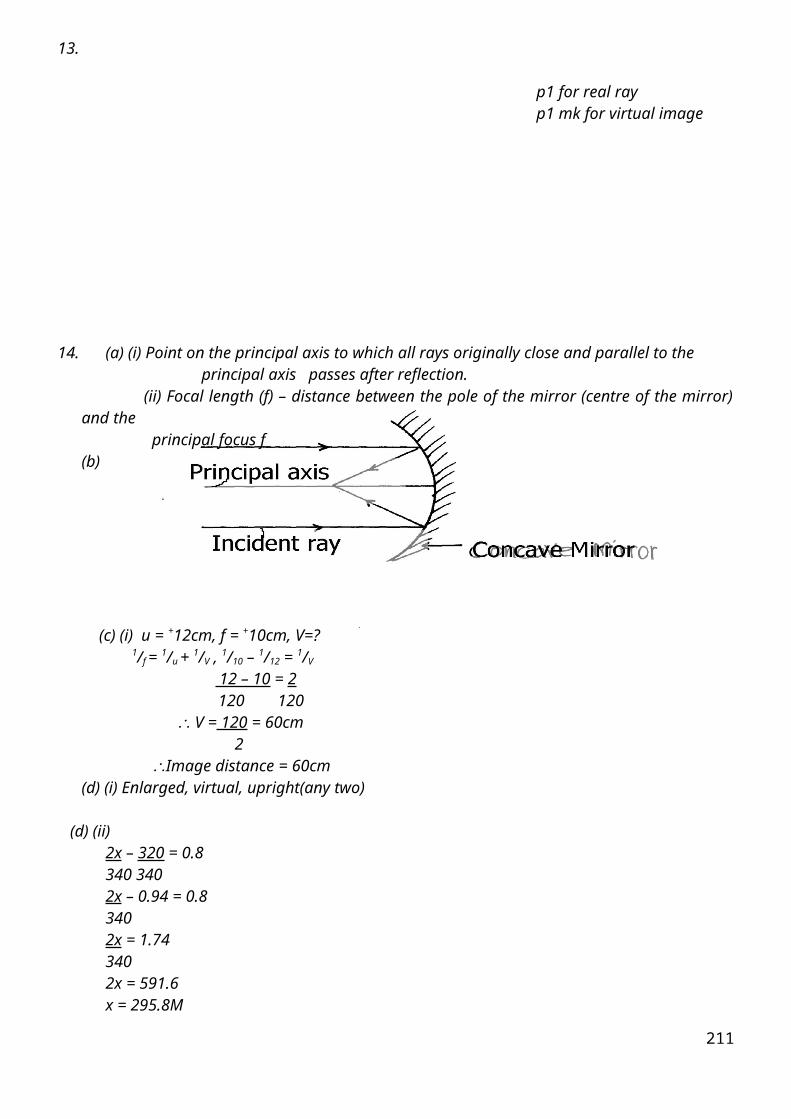
3M= 1.33 (1mk)
N/B:- You can also pick two points on the time to solve for M by substituting in equation and solving Simultaneously.
SOTIK DISTRICT Q 1. PART A:
x (cm) T (m)1 (m – 1 x
948984797570
0.80.70.60.50.40.3
1.061.121.191.271.331.43
(3 mks)f(i) Graph
- Labeling axes. p1 - Appropriate Scale. p1 - Plotting: 5 – 6 pts 2 p1 p1 (5 mks)
: 3 -4 pts p1 - Straight line p1
(ii) Slope - p1 (2 mks) Evaluation p1 (2 mks) Answer p (0.48 + 0.05) (ii) Given M = S when S =0
4.8 M = 0.48
4.8 = 0.1 kg p1
QUESTION 1: PART Bf (i) X1 = 7.5 cm p1 mk X2 = 50 cm p1 mk (ii) X2 = 6 cm p1 Y2 = 40 cmp1
X = 7.5 + 6 2 = 6.75 cm p1
Y = 40 + 40 2= 40 cm p1
(iii) 4f = (6.75) 2 – (40) 2 p140 p1
f = 10 cm p1 9
QUESTION 2b) (i) I = 0.12A + 0.01 p1 V = 2.6V + 0.1 p1 (ii) E = 3.0v (Max. range) p1d) Table
L (cm) 100 70 60 50 40 20I (A) 0.12 0.19 0.20 0.24 0.28 0.42V (v) 2.60 2.50 2.40 2.35 2.30 2.00
211
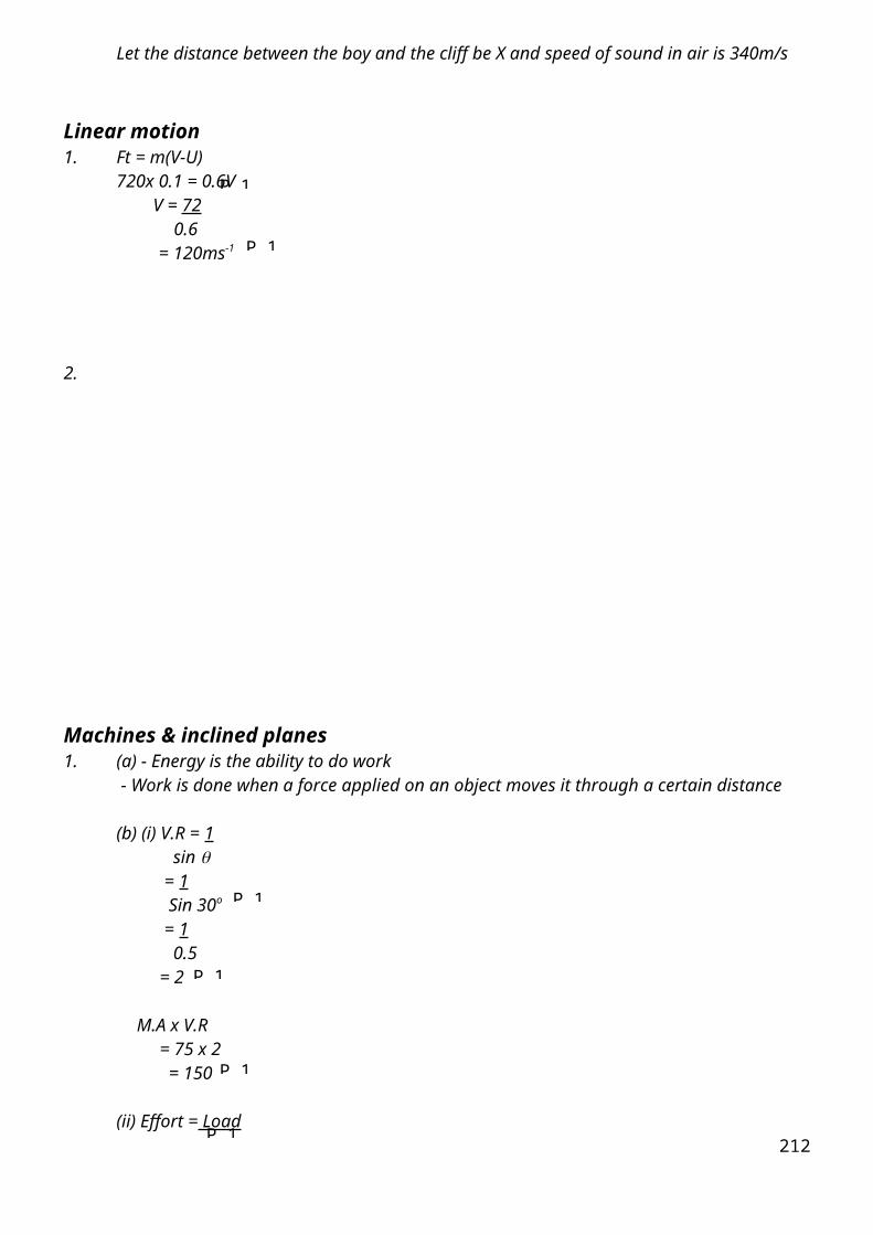
E-V 0.40 0.50 0.60 0.65 0.70 1.00(7 mks)
e) (i) Graph- Labeling axis p1 mk - Appropriate scale p1 mk- Plotting: 5 – 6 pts p2 mks
: 3 – 4 pts p1 mk- Straight line p1
(ii) Slope - p1 mk Evaluation - p1 mkAnswer - p1 mk
(iii) Slope of the graph = r, internal /resistance p1 3 mks
TRANS MARA DISTRICT1. (b) I = 1.00Amps V = 1.00Volts
(c) Length L(m) 00 0.1 0.2 0.3 0.4 0.5 0.6 0.7 0.8Voltmeter reading V (V) 1.00 1.10 1.20 1.25 1.30 1.35 1.40 1.45 1.45Ammeter reading I(A) 1.00 0.80 0.60 0.50 0.40 0.35 0.30 0.25 0.20
Increasing V 1mk Decreasing 1mk7-9 correct pairs = 2mks5-6 correct pairs = 1 ½mks3-4 correct pairs = 1mk2 correct pairs = ½ mk
Total = 7mks (d.) Graph
Labelling – both axes quantity and units shown -1mkScale-Plotting - (½mk each maximum) - 2mksStraight line – through 3 correctly plotted points- 1mk Total 5mks
(e) Gradient DV = 1.3 – 1.2 = 0.1 = ½ = 0.5 DI 0.6 – 0.4 0.2 Gradient = 0.5(f) (i) V = Ir + E when I = 0, V = E , y intercept E = 1.48 ± 0.1Volts (ii) Gradient S = -r r = -S = (0.5) = 0.5W2. (d)
Ucm Vcm U +V)cm1517192123252729
30.524.021.019.017.616.615.815.3
45.541.340.040.040.641.642.844.3
(e) On the graph paper – Labelling both axes – 1mk - scale – 1mk- Plotting (½mk each) max – 2mks Curve – 1mk
(f) Vm = 20cm (U + V)m = 39.9(g) (i) h1 = Vm = 20 = 10cm ± 0.2cm 2 2
212
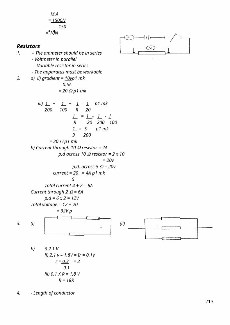
h2 = (U + V)m = 39.9 4 4 = 9.975cm ± 0.2(ii) h = h1 + h2 = 10 + 9.975 = 9.986cm ± 0.2 2 2(h) Value V when U + V = 41.6 V1 = 16.5cm ± 0.2 V2 = 24.5cm ± 0.2
213