mentor.ieee.org · web viewabstract: a phy and a mac layer for short-range optical wireless...
TRANSCRIPT

Draft D0 IEEE Std 802.15.7r1™-20xx
IEEE Standard forLocal and metropolitan area networks—
Part 15.7: Short-Range Wireless OpticalCommunication
Sponsor
LAN/MAN Standards Committee of theIEEE Computer Society
Approved 16 June 2011
IEEE-SA Standards Board
Abstract: A PHY and a MAC layer for short-range optical wireless communications using visible light in optically transparent media are defined. The visible light spectrum extends from 380 nm to 780 nm in wavelength. The standard is capable of delivering data rates sufficient to support audio and video multimedia services and also considers mobility of the visible link, compatibility with visible-light infrastructures, impairments due to noise and interference from sources like ambient light and a MAC layer that accommodates visible links. The standard adheres to applicable eye safety regulations.Keywords: IEEE 802.15.7, laser diode, LD, LED, light-emitting diode, short-range optical wireless communications, visible light, visible-light communication, VLC
The Institute of Electrical and Electronics Engineers, Inc.3 Park Avenue, New York, NY 10016-5997, USA
Copyright © 2011 by the Institute of Electrical and Electronics Engineers, Inc.All rights reserved. Published 6 September 2011. Printed in the United States of America.
IEEE and 802 are registered trademarks in the U.S. Patent & Trademark Office, owned by The Institute of Electrical and Electronics Engineers, Incorporated.
PDF: ISBN 978-0-7381-6665-0 STD97117Print: ISBN 978-0-7381-6666-7 STDPD97117
IEEE prohibits discrimination, harassment and bullying. For more information, visit http://www.ieee.org/web/aboutus/whatis/policies/p9-26.html.
No part of this publication may be reproduced in any form, in an electronic retrieval system or otherwise, without the prior written permission of the publisher.

IEEE Standards documents are developed within the IEEE Societies and the Standards Coordinating Committees of the IEEE Standards Association (IEEE-SA) Standards Board. The IEEE develops its standards through a consensus development process, approved by the American National Standards Institute, which brings together volunteers representing varied viewpoints and interests to achieve the final product. Volunteers are not necessarily members of the Institute and serve without compensation. While the IEEE administers the process and establishes rules to promote fairness in the consensus development process, the IEEE does not independently evaluate, test, or verify the accuracy of any of the information or the soundness of any judgments contained in its standards.
Use of an IEEE Standard is wholly voluntary. The IEEE disclaims liability for any personal injury, property or other damage, of any nature whatsoever, whether special, indirect, consequential, or compensatory, directly or indirectly resulting from the publication, use of, or reliance upon this, or any other IEEE Standard document.
The IEEE does not warrant or represent the accuracy or content of the material contained herein, and expressly disclaims any express or implied warranty, including any implied warranty of merchantability or fitness for a specific purpose, or that the use of the material contained herein is free from patent infringement. IEEE Standards documents are supplied “AS IS.”
The existence of an IEEE Standard does not imply that there are no other ways to produce, test, measure, purchase, market, or provide other goods and services related to the scope of the IEEE Standard. Furthermore, the viewpoint expressed at the time a standard is approved and issued is subject to change brought about through developments in the state of the art and comments received from users of the standard. Every IEEE Standard is subjected to review at least every five years for revision or reaffirmation, or every ten years for stabilization. When a document is more than five years old and has not been reaffirmed, or more than ten years old and has not been stabilized, it is reasonable to conclude that its contents, although still of some value, do not wholly reflect the present state of the art. Users are cautioned to check to determine that they have the latest edition of any IEEE Standard.
In publishing and making this document available, the IEEE is not suggesting or rendering professional or other services for, or on behalf of, any person or entity. Nor is the IEEE undertaking to perform any duty owed by any other person or entity to another. Any person utilizing this, and any other IEEE Standards document, should rely upon the advice of a competent professional in determining the exercise of reasonable care in any given circumstances.
Interpretations: Occasionally questions may arise regarding the meaning of portions of standards as they relate to specific applications. When the need for interpretations is brought to the attention of IEEE, the Institute will initiate action to prepare appropriate responses. Since IEEE Standards represent a consensus of concerned interests, it is important to ensure that any interpretation has also received the concurrence of a balance of interests.For this reason, IEEE and the members of its societies and Standards Coordinating Committees are not able to provide an instant response to interpretation requests except in those cases where the matter has previously received formal consideration. A statement, written or oral, that is not processed in accordance with the IEEE -SA Standards Board Operations Manual shall not be considered the official position of IEEE or any of its committees and shall not be considered to be, nor be relied upon as, a formal interpretation of the IEEE.At lectures, symposia, seminars, or educational courses, an individual presenting information on IEEE standards shall make it clear that his or her views should be considered the personal views of that individual rather than the formal position, explanation, or interpretation of the IEEE. Comments for revision of IEEE Standards are welcome from any interested party, regardless of membership affiliation with IEEE. Suggestions for changes in documents should be in the form of a proposed change of text, together with appropriate supporting comments. Recommendations to change the status of a stabilized standard should include a rationale as to why a revision or withdrawal is required.
Comments and recommendations on standards, and requests for interpretations should be addressed to:
Secretary, IEEE-SA Standards Board
445 Hoes Lane
Piscataway, NJ 08854
USA
Authorization to photocopy portions of any individual standard for internal or personal use is granted by the Institute of Electrical and Electronics Engineers, Inc., provided that the appropriate fee is paid to Copyright Clearance Center. To arrange for payment of licensing fee, please contact Copyright Clearance Center, Customer Service, 222 Rosewood Drive, Danvers, MA 01923 USA; +1 978 750 8400. Permission to photocopy portions of any individual standard for educational classroom use can also be obtained through the Copyright Clearance Center.

Introduction
This introduction is not part of IEEE Std 802.15.7-2011, IEEE Standard for Local and metropolitan area networks— Part 15.7: Short-Range Wireless Optical Communication using Visible Light.
Visible-light communication (VLC) transmits data by intensity modulating optical sources, such as light-emitting diodes (LEDs) and laser diodes (LDs), faster than the persistence of the human eye. VLC merges lighting and data communications in applications such as area lighting, signboards, streetlights, vehicles, traffic signals, and status indicators. This standard describes the use of VLC for wireless personal area networks (WPAN) and covers topics such as network topologies, addressing, collision avoidance, acknowledgement, performance quality indication, dimming support, visibility support, colored status indication and color-stabilization.
Notice to users
Laws and regulations
Users of these documents should consult all applicable laws and regulations. Compliance with the provisions of this standard does not imply compliance to any applicable regulatory requirements. Implementers of the standard are responsible for observing or referring to the applicable regulatory requirements. IEEE does not, by the publication of its standards, intend to urge action that is not in compliance with applicable laws, and these documents may not be construed as doing so.
Copyrights
This document is copyrighted by the IEEE. It is made available for a wide variety of both public and private uses. These include both use, by reference, in laws and regulations, and use in private self- regulation, standardization, and the promotion of engineering practices and methods. By making this document available for use and adoption by public authorities and private users, the IEEE does not waive any rights in copyright to this document.
Updating of IEEE documents
Users of IEEE standards should be aware that these documents may be superseded at any time by the issuance of new editions or may be amended from time to time through the issuance of amendments, corrigenda, or errata. An official IEEE document at any point in time consists of the current edition of the document together with any amendments, corrigenda, or errata then in effect. In order to determine whether a given document is the current edition and whether it has been amended through the issuance of amendments, corrigenda, or errata, visit the IEEE Standards Association website at http:// ieeexplore.ieee.org/xpl/standards.jsp, or contact the IEEE at the address listed previously.
For more information about the IEEE Standards Association or the IEEE standards development process, visit the IEEE-SA website at http://standards.ieee.org.
iv Copyright © 2011 IEEE. All rights reserved.
Errata
Errata, if any, for this and all other standards can be accessed at the following URL: http:// standards.ieee.org/reading/ieee/updates/errata/index.html. Users are encouraged to check this URL for errata periodically.
Interpretations
Current interpretations can be accessed at the following URL: http://standards.ieee.org/reading/ieee/interp/ index.html.
Patents
Attention is called to the possibility that implementation of this amendment may require use of subject matter covered by patent rights. By publication of this amendment, no position is taken with respect to the existence or validity of any patent rights in connection therewith. The IEEE is not responsible for identifying Essential Patent Claims for which a license may be required, for conducting inquiries into the legal validity or scope of Patents Claims or determining whether any licensing terms or conditions provided in connection with submission of a Letter of Assurance, if any, or in any licensing agreements are reasonable or non-discriminatory. Users of this amendment are expressly advised that determination of the validity of any patent rights, and the risk of infringement of such rights, is entirely their own responsibility. Further information may be obtained from the IEEE Standards Association.
Copyright © 2011 IEEE. All rights reserved. v
Participants
At the time this amendment was submitted to the IEEE-SA for approval, the IEEE P802.15.7 Working Group had the following membership:
Robert F. Heile, ChairRick Alfvin, Co-Vice Chair
Patrick W. Kinney, Co-Vice Chair and SecretaryJames P. K. Gilb, Working Group Technical Editor
Eun Tae Won, IEEE 802.15.7 ChairClint Chaplin, IEEE 802.15.7 Vice Chair
Richard D. Roberts, IEEE 802.15.7 Technical EditorSridhar Rajagopal, IEEE 802.15.7 Assistant Editor
Emad Afifi Michael DowGahng-Seop Ahn Dietmar EggertRoberto Aiello David EvansRichard Alfvin Charles FarlowTakamasa Asano John FarserotuArthur Astrin Kory FifieldTaehan Bae Will FilippoMichael Bahr Jeffrey FischbeckJohn Barr Michael FischerAnuj Batra George FlammerTuncer Baykas Ryosuke FujiwaraPhilip Beecher Noriyasu FukatsuGhulam Bhatti Kiyoshi FukuiGary Birk John GeigerMathew Boytim James GilbPeter Bradley Gregory GilloolyNancy Bravin Tim GodfreyDavid Britz Paul GordayMonique Brown Elad GottlibSverre Brubk Robert HallBrian Buchanan Shinsuke HaraJohn Buffington Hiroshi HaradaKiran Bynam Timothy HarringtonBrent Cain Robert HeileEdgar Callaway Rodney HemmingerChris Calvert Marco HernandezRadhakrishna Canchi Ryoichi HigashiRuben Cardozo Garth HillmanRussell Chandler Jin-Meng HoKuor-Hsin Chang Wei HongSoo-Young Chang Srinath HosurClint Chaplin David HowardHind Chebbo Jung-Hwan HwangChang-Soon Choi Ichirou IdaIn-Kyeong Choi Akio IsoSangsung Choi Adrian JenningsCiaran Connell Wuncheol JeongDavid Cypher Jorjeta JetchevaMatthew Dahl Steven JillingsDavid Davenport Seong-Soon JooMark Dawkins Tae-Gyu KangHendricus De Ruijter Shuzo KatoGang Ding Tatsuya KatoPaul Dixon Jeritt KentIgor Dotlic Prithpal Khakuria
Dae Ho KimDong-Sun KimYunjoo KimJeffrey KingPatrick KinneyRyuji KohnoFumihide KojimaBruce KraemerRaymond KrasinskiThomas KuernerMasahiro KurodaJohn LampeZhou LanKhanh LeCheolhyo LeeHyungsoo LeeMyung LeeYuro LeeDaniel LewisHuan-Bang LiLiang LiSang-Kyu LimJeremy LinkLu LiruMichael LynchRobert MasonTomokuni MatsumuraJeff McCulloughMichael McGillanMichael McInnisMichael McLaughlinCharles MilletDino MiniuttiSiamak MirnezamiRishi MohindraEmmanuel MonnerieRobert MoskowitzHamilton MoyPeter MurrayTheodore MyersKen NaganumaChiu NgoPaul NikolichJong-Ee OhDavid OlsonOkundu Omeni
vi Copyright © 2011 IEEE. All rights reserved.

Laurent Ouvry Michael Schmidt Khanh TranJames Pace Jean Schwoerer Jerry UptonHyung-Il Park Cristina Seibert Jana van GreunenSeung-Hoon Park Kunal Shah Hartman Van WykTaejoon Park Steve Shearer Billy VersoRanjeet Patro Stephen Shellhammer Bhupender VirkAlbert Petrick Jie Shen Khurram WaheedDalibor Pokrajac Shusaku Shimada Joachim WalewskiDaniel Popa Chang Sub Shin Junyi WangSteve Pope Cheol Ho Shin Quan WangClinton Powell Michael Sim Xiang WangRichard Powell Jonathan Simon Andy WardChang-Woo Pyo Jaeseung Son Scott WeikelSridhar Rajagopal Paul Stadnik Nicholas WestJayaram Ramasastry Rene Struik Mark WilburMarc Reed Chin-Sean Sum Ludwig WinkelIvan Reede Hui-Hsia Sung Eun Tae WonEmmanuel Riou Gu Sungi Alan WongRichard Roberts Ronald Tabroff Tao XingCraig Rodine Kenichi Takizawa Wen-Bin YangJune Roh Hirokazu Tanaka Yang YangBenjamin Rolfe Larry Taylor Kazuyuki YasukawaDidier Sagan James Tomcik Kamya YazdandoostKentaro Sakamoto Ichihiko Toyoda Kaoru YokooKamran Sayrafian-Pour David Tracey Mu ZhaoTimothy Schmidl Bin Zhen
Major technical contributions were received from the following individuals:Shadi Abu-Surra Il Soon Jang Sridhar RajagopalTaehan Bae Tae-Gyu Kang Richard RobertsMichael Bahr Dae Ho Kim Jaeseung SonSoo-Young Chang Doyoung Kim Joachim W. WalewskiClint Chaplin Sang-Kyu Lim Euntae WonPraveen Gopalakrishnan Eran Pisek Atsuya Yokoi
Copyright © 2011 IEEE. All rights reserved. vii
The following members of the individual balloting committee voted on this standard. Balloters may have voted for approval, disapproval, or abstention.Richard Alfvin Shinkyo KakuMark Anderson Masahiko KanekoButch Anton Hyunjeong KangTaehan Bae Noh-gyoung KangYoungkyo Baek Tae-gyu KangNancy Bravin Piotr KarockiVern Brethour Stuart J. KerryKiran Bynam Sehoon KimWilliam Byrd Tae KimJuan Carreon Yongbum KimSoo-young Chang Dongkeon KongYoungbin Chang Bruce KraemerClint Chaplin Hyukchoon KwonYawgeng Chau Sungjin LeeYi-ming Chen Charles LennonChihong Cho Michael LererJaeweon Cho Ying LiHokyu Choi Jan-ray LiaoKeith Chow Chiwoo LimCharles Cook Hyoung-kyu LimJoseph Decuir Nae Hyun LimThomas Dineen Sang-kyu LimGregory Gillooly Daniel LubarRandall Groves William LumpkinsC. Guy Elvis MaculubaRobert Heile Apurva ModyMarco Hernandez Emmanuel MonnerieTetsushi Ikegami Peter MurrayAkio Iso Michael S. NewmanAtsushi Ito Satoshi ObaraRaj Jain Chris OsterlohOyvind Janbu Satoshi OyamaJaehyuk Jang Jeongho ParkJunghoon Jee Jungshin ParkSuryong Jeong Seung-hoon ParkTal Kaitz Sung-eun Park
James PetranovichSubburajan PonnuswamyClinton PowellVenkatesha PrasadSridhar RajagopalJayaram RamasastryMaximilian RiegelRobert RobinsonRandal RoebuckWon Il RohBret RothenbergRandall SafierBartien SayogoCristina SeibertJaejeong ShimGil ShultzJaeseung SonJung Je SonKapil SoodThomas StaraiRene StruikWalter StrupplerMark SturzaIchihiko ToyodaMark-rene UchidaBhupender VirkGeorge VlantisJoachim WalewskiStanley WangHung-yu WeiLudwig WinkelAndreas WolfEun Tae WonHyunkyu YuOren Yuen
viii Copyright © 2011 IEEE. All rights reserved.

When the IEEE-SA Standards Board approved this standard on 16 June 2011, it had the following membership:
Richard H. Hulett, ChairJohn Kulick, Vice Chair
Robert M. Grow, Past ChairJudith Gorman, Secretary
Masayuki Ariyoshi Jim Hughes Gary RobinsonWilliam Bartley Joseph L. Koepfinger* Jon Walter RosdahlTed Burse David J. Law Sam SciaccaClint Chaplin Thomas Lee Mike SeaveyWael Diab Hung Ling Curtis SillerJean-Philippe Faure Oleg Logvinov Phil WinstonAlexander Gelman Ted Olsen Howard L. WolfmanPaul Houzé Don Wright
*Member Emeritus
Also included are the following nonvoting IEEE-SA Standards Board liaisons:
Satish Aggarwal, NRC RepresentativeRichard DeBlasio, DOE RepresentativeMichael Janezic, NIST Representative
Catherine BergerIEEE Project Editor
Patricia GerdonIEEE Standards Program Manager, Technical Program Development
Copyright © 2011 IEEE. All rights reserved. ix

x Copyright © 2011 IEEE. All rights reserved.

OPTICAL COMMUNICATION IEEE Std 802.15.7r1-20xx
1. Overview.............................................................................................................................................. 1
1.1 Scope............................................................................................................................................ 11.2 Purpose......................................................................................................................................... 1
2. Normative references ........................................................................................................................... 2
3. Definitions, acronyms, and abbreviations............................................................................................ 2
3.1 Definitions ................................................................................................................................... 23.2 Acronyms and abbreviations ....................................................................................................... 4
4. General description .............................................................................................................................. 5
4.1 Introduction.................................................................................................................................. 54.2 Network topologies...................................................................................................................... 64.3 Huawei Version of Network topologies ...................................................................................... 84.4 Modulation-domain spectrum...................................................................................................... 94.5 Architecture ............................................................................................................................... 104.6 Functional overview .................................................................................................................. 194.7 Security ...................................................................................................................................... 234.8 Concept of primitives................................................................................................................. 24
5. Huawei MAC protocol specification ................................................................................................. 24
5.1 Peer-to-peer................................................................................................................................ 255.2 Star ............................................................................................................................................. 255.3 Coordinated................................................................................................................................ 365.4 MAC frame formats................................................................................................................... 43
6. MAC protocol specification............................................................................................................... 60
6.1 PureLiFi MAC Superframe Structure (16/310r0)...................................................................... 606.2 MAC functional description ...................................................................................................... 716.3 Fraunhofer Superframe Structure ............................................................................................ 1286.4 MAC frame formats................................................................................................................. 1296.5 Fraunhofer MAC frame formats (16/356r0) ............................................................................ 1496.6 PureLiFi MAC frame formats (16/310r0) ............................................................................... 1646.7 MAC command frames............................................................................................................ 177
7. MAC sublayer service specification ................................................................................................ 197
7.1 Overview.................................................................................................................................. 1977.2 MAC data service .................................................................................................................... 1987.3 MAC management service....................................................................................................... 2077.4 Huawei MAC primitives.......................................................................................................... 2607.5 MAC constants and PIB attributes........................................................................................... 2787.6 Optical-clock-rate selection ..................................................................................................... 2907.7 Message sequence charts illustrating MAC-PHY interaction ................................................. 296
8. Security suite specifications............................................................................................................. 303
8.1 Overview.................................................................................................................................. 3038.2 Functional description.............................................................................................................. 3048.3 Security operations .................................................................................................................. 3118.4 Auxiliary Security header ........................................................................................................ 313
Copyright © 2011 IEEE. All rights reserved. 0

IEEE Std 802.15.7r1-20xx IEEE STANDARD FOR SHORT-RANGE WIRELESS
8.5 Security-related MAC PIB attributes....................................................................................... 317
9. PHY layer specification ................................................................................................................... 322
9.1 Overview.................................................................................................................................. 3229.2 Operating modes ...................................................................................................................... 3229.3 General requirements ............................................................................................................... 3289.4 Data modes .............................................................................................................................. 3329.5 Dimming and flicker mitigation .............................................................................................. 3339.6 PPDU format............................................................................................................................ 3449.7 PureLiFi PPDU Format ........................................................................................................... 3709.8 Fraunhofer PPDU Format ........................................................................................................ 3829.9 Frame structure ........................................................................................................................ 382
10. PHY service specifications .............................................................................................................. 385
10.1 Overview.................................................................................................................................. 38510.2 PHY management service........................................................................................................ 38610.3 PHY data service ..................................................................................................................... 39310.4 PHY enumeration description.................................................................................................. 39610.5 PHY constants and PIB attributes............................................................................................ 396
11. PHY I specifications ........................................................................................................................ 400
11.1 Reference modulator diagram.................................................................................................. 40011.2 Outer forward error correction encoder ................................................................................... 40111.3 Interleaving and puncturing block ........................................................................................... 40111.4 Inner forward error correction encoder.................................................................................... 40311.5 Run-length limiting encoder .................................................................................................... 40511.6 Data mapping for VPPM ......................................................................................................... 406
12. PHY II specifications....................................................................................................................... 407
12.1 Reference modulator diagram.................................................................................................. 40712.2 Forward error correction encoder ............................................................................................ 40712.3 Run-length limiting encoder .................................................................................................... 40812.4 Data mapping for VPPM ......................................................................................................... 408
13. PHY III specifications ..................................................................................................................... 408
13.1 Reference modulator diagram.................................................................................................. 40813.2 Scrambler ................................................................................................................................. 40913.3 Channel encoder ...................................................................................................................... 41013.4 CSK constellation overview .................................................................................................... 41013.5 CSK constellation design rules ................................................................................................ 41113.6 Data mapping for CSK ............................................................................................................ 41413.7 Valid color band combinations ................................................................................................ 41513.8 CSK color mapping ................................................................................................................. 41813.9 CSK calibration at the receiver ................................................................................................ 418
14. PHY A specifications....................................................................................................................... 420
14.1 Undersampled Frequency Shift ON-OFF Keying (UFSOOK)................................................ 42014.2 Twinkle VPPM ........................................................................................................................ 42314.3 S2-PSK..................................................................................................................................... 42614.4 S2+DMS-PSK.......................................................................................................................... 428
1 Copyright © 20xx IEEE. All rights reserved.

OPTICAL COMMUNICATION IEEE Std 802.15.7r1-20xx
14.5 Offset-VPWM (SNUST 16/353r2) .......................................................................................... 43314.6 CSM (withdrawn) .................................................................................................................... 442
15. PHY B specifications....................................................................................................................... 442
15.1 RS-FSK (rolling shutter frequency shift keying)..................................................................... 44215.2 Compatible M-FSK Modulation Scheme ................................................................................ 44515.3 C-OOK..................................................................................................................................... 44815.4 3 mode PWM/PPM (Panasonic 16/365r0 - need to re-org this section).................................. 451
16.PHY C..............................................................................................................................................
459
16.1 2D-sequential color code ......................................................................................................... 45916.2 VTASC .................................................................................................................................... 45916.3 Invisible data-embedding......................................................................................................... 46616.4 PAPM....................................................................................................................................... 46616.5 CSM (withdrawn) .................................................................................................................... 46616.6 Kookmin Invisible code (16/358r0)......................................................................................... 46716.7 Invisible Data embedded display Tx Schemes (16/354r0) ...................................................... 472
17.PHY VII ...........................................................................................................................................
486
17.1 Fraunhofer High-bandwidth PHY (ref. 16/356r0) ................................................................... 48617.2 PureLiFi Low-bandwidth PHY................................................................................................ 511
Annex A ...................................................................................................................................................543
A.1 General............................................................................................................................. 543A.2 Regulatory documents ..................................................................................................... 544
Annex B ...................................................................................................................................................546
B.1 IEEE 802.2 convergence sublayer ................................................................................... 546B.1.1MA-UNITDATA.request........................................................................................ 546B.1.2MA-UNITDATA.indication ................................................................................... 547B.1.3MA-UNITDATA-STATUS.indication ................................................................... 548
Annex C ...................................................................................................................................................550
Annex D ...................................................................................................................................................551
Annex E ...................................................................................................................................................557
E.1 Introduction—Dynamic displays vs. addressed displays ................................................ 557E.2 Dynamic displays............................................................................................................. 557
E.2.1Operation mechanism.............................................................................................. 557E.2.2Reduced brightness mitigation on VLC dynamic displays ..................................... 558E.2.3VLC application using dynamic displays................................................................ 559
E.3 Addressed displays .......................................................................................................... 560E.3.1LCD display using LED backlighting modulation.................................................. 560E.3.2LED pixel modulation ............................................................................................. 560
Annex F ...................................................................................................................................................562
Copyright © 2011 IEEE. All rights reserved. 2

IEEE Standard forLocal and metropolitan area networks—
Part 15.7: Short-Range Wireless OpticalCommunicationIMPORTANT NOTICE: This standard is not intended to ensure safety, security, health, or environmental protection. Implementers of the standard are responsible for determining appropriate safety, security, environmental, and health practices or regulatory requirements.
This IEEE document is made available for use subject to important notices and legal disclaimers. These notices and disclaimers appear in all publications containing this document and may be found under the heading “Important Notice” or “Important Notices and Disclaimers Concerning IEEE Documents.” They can also be obtained on request from IEEE or viewed at http://standards.ieee.org/IPR/disclaimers.html.
1. Overview
1.1 Scope
This standard defines a PHY and MAC layer for short-range optical wireless communications using visible light in optically transparent media. The visible light spectrum extends from 380 nm to 780 nm in wavelength. The standard is capable of delivering data rates sufficient to support audio and video multimedia services and also considers mobility of the visible link, compatibility with visible-light infrastructures, impairments due to noise and interference from sources like ambient light and a MAC layer that accommodates visible links. The standard adheres to applicable eye safety regulations.
1.2 Purpose
The purpose of this standard is to provide a global standard for short-range optical wireless communication using visible light. The standard provides (i) access to several hundred THz of unlicensed spectrum; (ii) immunity to electromagnetic interference and noninterference with Radio Frequency (RF) systems; (iii) additional security by allowing the user to see the communication channel; and (iv) communication augmenting and complementing existing services (such as illumination, display, indication, decoration, etc.) from visible-light infrastructures.
Copyright © 2011 IEEE. All rights reserved. 1

IEEE Std 802.15.7r1-20xx IEEE STANDARD FOR SHORT-RANGE WIRELESS
2. Normative references
The following referenced documents are indispensable for the application of this document (i.e., they must be understood and used, so each referenced document is cited in text and its relationship to this document is explained). For dated references, only the edition cited applies. For undated references, the latest edition of the referenced document (including any amendments or corrigenda) applies.
ANSI/INCITS 373: Fiber Channel Framing and Signaling Interface (FC-FS).1
IEEE Std 802.15.4TM-2006, IEEE Standard for Information technology—Telecommunications and information exchange between systems—Local and metropolitan area networks—Specific requirements— Part 15.4: Wireless Medium Access Control (MAC) and Physical Layer (PHY) Specifications for Low-
Rate Wireless Personal Area Networks (LR-WPANs).2, 3
ITU-T I.432.1, Series I: Integrated Services Digital Network, ISDN user-network interfaces—Layer 1RecommendationsB-ISDN user-network interface—Physical layer specification: General characteristics,
http://www.itu.int/rec/T-REC-I.432.1-199902-I/en.4
3. Definitions, acronyms, and abbreviations
3.1 Definitions
For the purposes of this document, the following terms and definitions apply. The IEEE Standards Dictio-
nary: Glossary of Terms & Definitions should be consulted for terms not defined in this clause.5
color function: A function that provides information, such as device status and channel quality, to the human eye via color.
color-shift keying (CSK): sources, which keeps the communication.
A modulation scheme for visible-light communication involving multiple light average emitted optical color and the total optical power constant during
color stabilization: A control loop for the stabilization of the color emitted by color-shift-keying transmitters.
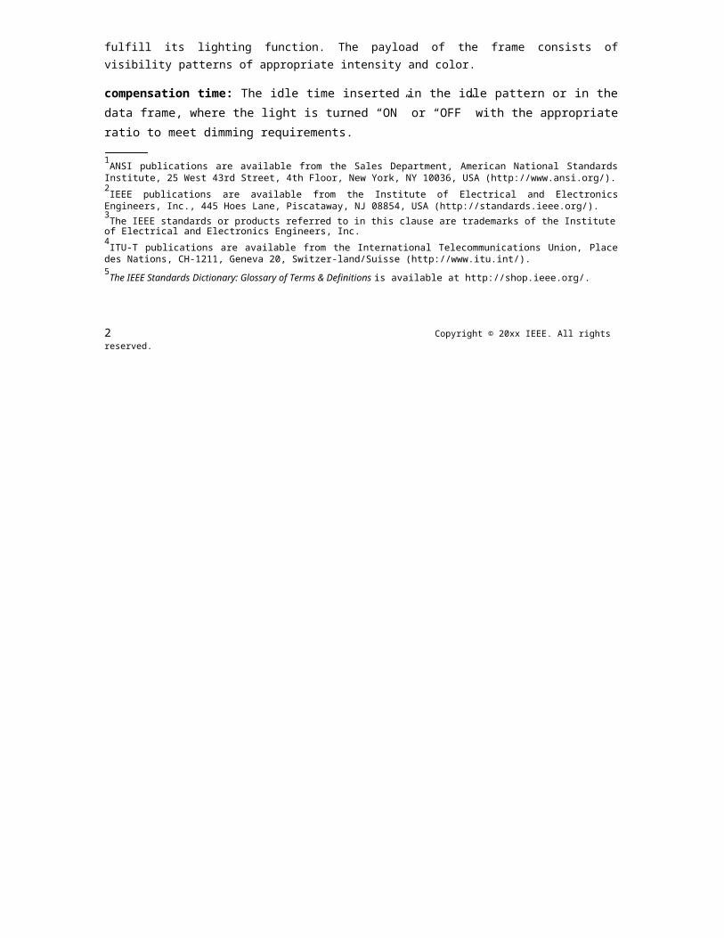
color visibility dimming (CVD) frame: A frame used for color, visibility and dimming support. The color visibility dimming frame visually provides information such as communication status and channel quality to the user via various colors. The color visibility dimming frame may also be sent during idle or receive modes of operation for continuous visibility and dimming support. During the color visibility dimming frame transmission, the device is still emitting light while not communicating, and it is thus able to fulfill its lighting function. The payload of the frame consists of visibility patterns of appropriate intensity and color.
compensation time: The idle time inserted in the idle pattern or in the data frame, where the light is turned “ON” or “OFF” with the appropriate ratio to meet dimming requirements.
1ANSI publications are available from the Sales Department, American National Standards Institute, 25 West 43rd Street, 4th Floor, New York, NY 10036, USA (http://www.ansi.org/).2IEEE publications are available from the Institute of Electrical and Electronics Engineers, Inc., 445 Hoes Lane, Piscataway, NJ 08854, USA (http://standards.ieee.org/).3The IEEE standards or products referred to in this clause are trademarks of the Institute of Electrical and Electronics Engineers, Inc.4ITU-T publications are available from the International Telecommunications Union, Place des Nations, CH-1211, Geneva 20, Switzer-land/Suisse (http://www.itu.int/).5The IEEE Standards Dictionary: Glossary of Terms & Definitions is available at http://shop.ieee.org/.
2 Copyright © 20xx IEEE. All rights reserved.

OPTICAL COMMUNICATION IEEE Std 802.15.7r1-20xx
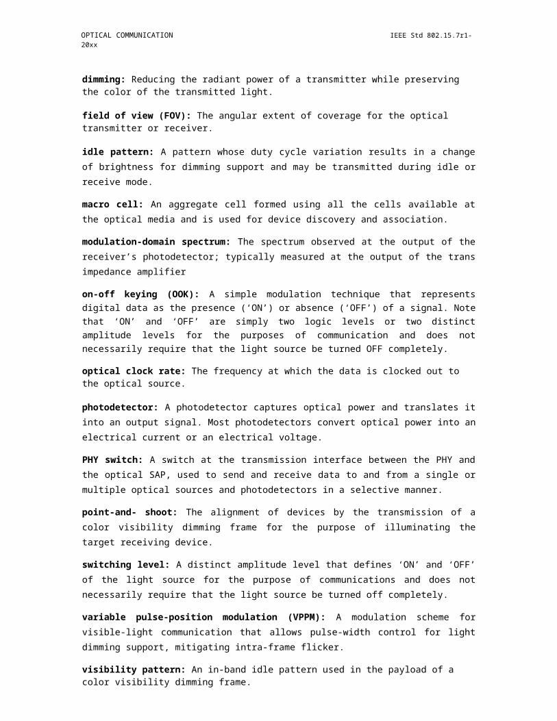
dimming: Reducing the radiant power of a transmitter while preserving the color of the transmitted light.
field of view (FOV): The angular extent of coverage for the optical transmitter or receiver.
idle pattern: A pattern whose duty cycle variation results in a change of brightness for dimming support and may be transmitted during idle or receive mode.
macro cell: An aggregate cell formed using all the cells available at the optical media and is used for device discovery and association.
modulation-domain spectrum: The spectrum observed at the output of the receiver’s photodetector; typically measured at the output of the trans impedance amplifier
on-off keying (OOK): A simple modulation technique that represents digital data as the presence (‘ON’) or absence (‘OFF’) of a signal. Note that ‘ON’ and ‘OFF’ are simply two logic levels or two distinct amplitude levels for the purposes of communication and does not necessarily require that the light source be turned OFF completely.
optical clock rate: The frequency at which the data is clocked out to the optical source.
photodetector: A photodetector captures optical power and translates it into an output signal. Most photodetectors convert optical power into an electrical current or an electrical voltage.
PHY switch: A switch at the transmission interface between the PHY and the optical SAP, used to send and receive data to and from a single or multiple optical sources and photodetectors in a selective manner.
point-and- shoot: The alignment of devices by the transmission of a color visibility dimming frame for the purpose of illuminating the target receiving device.
switching level: A distinct amplitude level that defines ‘ON’ and ‘OFF’ of the light source for the purpose of communications and does not necessarily require that the light source be turned off completely.
variable pulse-position modulation (VPPM): A modulation scheme for visible-light communication that allows pulse-width control for light dimming support, mitigating intra-frame flicker.
visibility pattern: An in-band idle pattern used in the payload of a color visibility dimming frame.
spatial phase (S_Phase): the phase of a discrete waveform which is built from the states of LEDs on a group those captured and decoded from a global shutter image.
global phase shift: the phase value that all LEDs in a data group together are shifted to transmit data.
data group: A group of data LEDs those operate together to transmit a data symbol
reference group: A group of reference LEDs those operate together to transmit a reference signal
S_Phase shift: the abstraction value between the spatial phase values of data group and of the reference group.
(long exposure) bad-sampled image: an image sampling that captures an unclear sate of LED (neither ON nor OFF) due to long exposure time.
x_state (of a LED): an unclear state that observed from a bad-sampled image.
Copyright © 2011 IEEE. All rights reserved. 3

IEEE Std 802.15.7r1-20xx IEEE STANDARD FOR SHORT-RANGE WIRELESS
SM-PSK (e.g. S2-PSK; S8-PSK; etc.): Spatial Multiple-Phase Shift Keying
DSM-PSK (e.g. DS8-PSK): Dimmable SM-PSK
3.2 Acronyms and abbreviations
A/D analog-to-digital converterACK acknowledgmentAES advanced encryption standardAR acknowledgment requestBE backoff exponentBI beacon intervalBO beacon orderBSN beacon-sequence numberCAP contention access periodCC convolutional codeCCA clear channel assessmentCDR clock and data recoveryCFP contention-free periodCIE Commission Internationale de l'Eclairage (International Commission on Illumination)CRC cyclic redundancy checkCSK color-shift keyingCSMA/CA carrier sense multiple access with collision avoidanceCVD color visibility dimmingD/A digital-to-analog converterD/L downlinkDC direct currentDME device management entityDSN data-sequence numberED energy detectionENC encryption modeFCS frame check sequenceFDM frequency division multiplexingFEC forward error correctionFER frame-error ratioFLP fast locking patternFLR fast link recoveryFOV field of viewGF Galois fieldGTS guaranteed time slotHCS header-check sequenceHP hopping patternIFS interframe spaceID identifierIE information elementLD laser diodeLED light-emitting diodeLIFS long interframe spaceLLC logical link controlLPDU logical link control protocol data unitLOS line of sightMAC medium access controlMCPS medium-access-control common-part sublayer
4 Copyright © 20xx IEEE. All rights reserved.

OPTICAL COMMUNICATION IEEE Std 802.15.7r1-20xx
MCS modulation and coding schemeMD mobile deviceMFR medium-access-control footerMFTP maximum flickering-time periodMHR medium-access-control headerMIC message-integrity codeMLME medium-access-control link-management entityMPDU medium-access-control protocol-data unitMSDU medium-access-control service-data unitNB number of backoffsOOK on-off keyingPAN personal-area networkPD physical-layer dataPHR physical-layer headerPHY physical layerPIB physical-layer personal-area-network information basePID personal-area-network identifierPLME physical-layer management entityPPDU physical-layer data unitPSDU PHY service data unitPWM pulse-width modulationP2MP point-to-multipointP2P peer-to-peerQoS quality of serviceRIFS reduced interframe spaceRLL run-length limitedRS Reed-SolomonRX receiverSAP service access pointSHR synchronization headerSIFS short interframe spaceSPDU session-protocol data unitSO superframe orderSSCS service-specific convergence sublayerTDP topology dependent patternTRX transceiverTX transmitterU/L uplinkVPAN visible-light communication personal area networkVLC visible-light communicationVPPM variable pulse-position modulationWPAN wireless personal area networkWQI wavelength quality indication
4. General description
4.1 Introduction
Visible-light communication (VLC) transmits data by intensity modulating optical sources, such as light-emitting diodes (LEDs) and laser diodes (LDs), faster than the persistence of the human eye. VLC merges lighting and data communications in applications such as area lighting, signboards, streetlights, vehicles,
Copyright © 2011 IEEE. All rights reserved. 5
IEEE Std 802.15.7r1-20xx IEEE STANDARD FOR SHORT-RANGE WIRELESS
and traffic signals. This standard describes the use of VLC for wireless personal area networks (WPAN). Some of the characteristics found in this standard are as follows:
a) Star, peer-to-peer, or broadcast operationb) 16-bit short or 64-bit extended addressesc) Scheduled or slotted random access with collision avoidance transmissiond) Fully acknowledged protocol for transfer reliabilitye) Wavelength quality indication (WQI)f) Dimming supportg) Visibility supporth) Color function supporti) Color-stabilization support
4.2 Network topologies
As shown in Table 1, three classes of devices are considered for VLC: infrastructure, mobile, and vehicle.
Table 1—Device classification
Infrastructure Mobile Vehicle
Fixed coordinator Yes No No
Power supply Ample Limited Moderate
Form factor Unconstrained Constrained Unconstrained
Light source Intense Weak Intense
Physical mobility No Yes Yes
Range Short/long Short Long
Data rates High/low High Low
The IEEE 802.15.7r1 visible-light communication personal area network (VPAN) standard maps the intended applications to four topologies: peer-to-peer, star, broadcast and coordinated, as shown in Figure
1. Moreover, two advanced network functionalities are supported, relaying and heterogeneous networking
of OWC and RF, as shown in Fig. 1a. The IEEE 802.15.7 visible-light communication personal area network (VPAN) standard maps the intended applications to three topologies: peer-to-peer, star, and broadcast, as shown in Figure 1.
In the star topology, the communication is established between devices and a single central controller, called the coordinator. In the peer-to-peer topology, one of the two devices in an association takes on the role of the coordinator. In the star topology, the communication is established between devices and a single central controller, called the coordinator. In the peer-to-peer topology, one of the two devices in an association takes on the role of the coordinator. In the coordinated topology, multiple devices communicate with multiple coordinators, supervised by a global controller. The global controller has a fixed network link to each coordinator. Note that the functionality of the global controller is not part of this standard.In addition, two advanced network functionalities may be enabled: relaying and heterogeneous RF&OWC. With the relaying functionality, an intermediate relay node is introduced between the coordinator and the device. With the heterogeneous RF&OWC functionality, data transmission over the optical wireless link can be combined with a parallel radio-based wireless link.
Each device or coordinator has a unique 64-bit address. When a device associates with a coordinator it is allowed to be allocated a shortened 16-bit address. Either address is allowed to be used for communication within the VPAN managed by the coordinator. The coordinator might often be mains powered, while the
devices will often be battery powered. Each device, coordinator or relay node has a unique 64-bit address. When a device associates with a coordinator or relay node it is allowed to be allocated a shortened 16-bit address. Either address is allowed to be used for communication within the VPAN managed by the coordinator, the relay node or the global controller. The coordinator, the relay node and the global controller might often be mains powered, while the devices will often be battery powered.
Figure 1—Supported MAC topologies
Figure 1a —Advanced network functionalities
6 Copyright © 20xx IEEE. All rights reserved.
OPTICAL COMMUNICATION IEEE Std 802.15.7r1-20xx
visibility
peersupport
across all-to- -star broadcast topologiespeer
coordinator
device
Figure 1—Supported MAC topologies
Each independent VPAN has an identifier, as defined in 6.4.1.3 and 6.4.1.5. This VPAN identifier allows communication between devices within a network using short addresses. The mechanism by which VPAN identifiers are chosen is outside the scope of this standard.
The network formation is performed by the higher layer, which is not part of this standard. Apart from the peer-to-peer and star topologies, IEEE 802.15.7 devices are also allowed to operate in a broadcast only topology without being part of a network, i.e., without being associated to any device or having any devices associated to them. A brief overview on how each supported topology may be formed is provided in 4.2.1, 4.2.2, and 4.2.3. The network formation is performed by the higher layer, which is not part of this standard. Apart from the peer-to-peer and star topologies, IEEE 802.15.7r1 devices are also allowed to operate in a broadcast-only topology without being part of a network, i.e., without being associated to any device or having any devices associated to them. Moreover, the devices are allowed to operate in the coordinated topology, where a global controller is introduced to perform higher layer functions such as handover between adjacent coordinators and interference management. In addition, IEEE 802.15.7r1 devices are allowed to operate with relay network functionality, where an additional relay is used between the device and the coordinator. Finally, the devices are allowed to operate with heterogeneous RF&OWC network functionality, where an additional bidirectional radio link is introduced, where the optical link is either unidirectional or bidirectional. A brief overview on how each supported topology may be formed is provided in 4.2.1, 4.2.2, 4.2.3, 4.2.4, 4.2.5 and 4.2.6.
Visibility support is also provided across all topologies to maintain the illumination function in the absence of communication or in the idle or receive modes of operation. The purpose of this mode is to maintain illumination and mitigate flicker. In case illumination function is required, visibility support is also provided in the absence of communication or in the idle or receive modes of operation. The purpose of this mode is to maintain illumination and mitigate flicker.
4.2.1 Peer-to-peer topology
The basic structure of a peer-to-peer topology is illustrated in Figure 1. In a peer-to-peer topology, each device is capable of communicating with any other device within its coverage area. In a peer-to-peer topology, one of the peers acts as a coordinator. One peer defaults as the coordinator, for instance, by virtue of being the first device to communicate on the channel.
4.2.2 Star topology
The basic structure of a star topology is illustrated in Figure 1. All star networks operate independently from all other star networks currently in operation. This is achieved by choosing a VPAN identifier that is not currently used by any other network within the coverage area. Once the VPAN identifier is chosen, the
coordinator allows other devices to join its network. The higher layer is allowed to use the procedures described in 6.2.2 and 6.2.4 to form a star network.
4.2.3 Broadcast topology
The basic structure of a broadcast topology is illustrated in Figure 1. The device in a broadcast mode can transmit a signal to other devices without forming a network. The communication is uni-directional and the destination address is not required.
4.2.4 Coordinated topology
The basic structure of a coordinated topology is illustrated in Figure 1. In the coordinated topology, multiple coordinators are connected to each other and to a global controller through backhaul network. The backhaul is out of the scope of this specification. Multiple VPANs are coordinated by the global controller. The global controller may be in charge of various kinds of coordination among the multiple VPANs, e.g. handover, interference management, VPAN status monitoring, etc.
4.2.5 Relay functionality
With the relay functionality, an intermediate relay is used to assist a transmission via a direct optical wireless link. With the relay functionality, each relay supports different duplexing and relay modes. For full duplex (FD), the relay receives and transmits data simultaneously, while in half duplex (HD), the relay receives the data in one time slot and retransmits it in another transmission slot. The relay supports two modes; amplify-and-forward (AF), and decode-and-forward (DF).
- In AF mode, the RD receives the data from the coordinator, which are then retransmitted after amplification.
- In DF mode, the received data is decoded by the relay and then retransmitted to the destination device.
In case the device is disconnected from the coordinator, a relay search request is conducted, including the relay capabilities. The coordinator broadcasts a relay search request frame. Each relay replies back on the control channel with its own capabilities including duplexing and relaying modes. The coordinator selects the relay that provides the best connectivity. The coordinator initiates a relay link setup procedure between the coordinator, the selected relay and the device. A connection remains active until the direct link between the coordinator and the device is reinitiated and the coordinator requires a termination of the link between the coordinator and the relay.
4.2.6 Heterogeneous RF & OWC functionality
The IEEE 802.15.7r1 specification supports heterogeneous RF&OWC functionality. The functionality may be used in conjunction with different network topologies as demonstrated in Figure 2. The RF AP may be co-located with a coordinator or a global controller. Each coordinator provides optical wireless links to the devices while the RF AP provides a parallel RF link.
Figure 2—Heterogeneous RF&OWC funcationality
As shown in Table xx, three types of devices according to the capabilities in supporting OWC and RF are considered for IEEE 802.15.7r1. Type 1 devices support OWC only operations. Type 2 devices support OWC downlink operations as well as RF bidirectional operations. Type 3 devices support OWC bidirectional operations as well as RF bidirectional operations.
Type 2 and type 3 devices can operate via OWC and RF simultaneously. In the downlink, aggregated transmission through both OWC link and RF link may be used, besides switching between OWC link and RF link. For the coordinated topology, command frames or ACK frames with destination address set to the coordinator may be first transmitted to the global controller through RF link and then forwarded to the coordinator through the backhaul link. Specification of these networking functionalities is out of scope in 802.15.7r1.
Table xx—Device classification according to supported RF capabilities
Device Type
RF Down
RF Uplink
OWC
OWC UplinkLink Downlink
Type 1 x x
Type 2 x x x
Type 3 x x x x
Copyright © 2011 IEEE. All rights reserved. 7

IEEE Std 802.15.7r1-20xx IEEE STANDARD FOR SHORT-RANGE WIRELESS
4.3 Huawei Version of Network topologies
The IEEE 802.15.7r1 specification supports three topologies: peer-to-peer, star, and coordinated, as show in Figure 2.
Figure 2—Supported MAC topologies
In the peer to peer topology, two devices can establish a connection through the optical wireless link and communicate to each other directly within its coverage area. One of the peers acts as a coordinator, usually the one being the first device to communicate on the channel.
In the star topology, a VPAN comprises a coordinator and one or multiple devices. The coordinator can provide optical wireless access to the devices.
In the coordinated topology, multiple coordinators are connected to each other and to a global controller through the backhaul link. The backhaul link can be either a wired connection (Power line link, Ethernet link, etc.) or a wireless connection (LTE link, WiMAX link, etc.), which is out of the scope of this specification. Multiple VPANs are coordinated by the global controller. The global controller is in charge of various kinds of coordination among the multiple VPANs, e.g. handover, interference management, VPAN status monitoring, etc.
Each VPAN shall have a unique VPAN ID, which is chosen by the coordinator when it established the VPAN. Each device and the coordinator have a unique 64 bits extended address and a [8] bits short address. The 64 bits extended address is assigned by the manufactures of the devices. The [8] bit short address is assigned by the coordinator once the device has successfully associated with the VPAN. The short address of the coordinator is chosen by itself when the coordinator established the VPAN.
4.3.1 Heterogeneous network of VLC and RF
The IEEE 802.15.7r1 specification supports heterogeneous network of VLC and RF. The topology is shown in Figure 1 2. Each coordinator is connected to the Global controller and other coordinators through backhaul link. The Global controller is co-located with a RF AP. Each coordinator provides optical wireless access to devices while the RF AP co-located with global controller provides RF access to one or multiple devices
Figure 1 2 heterogeneous network comprised of RF links and VLC links
8 Copyright © 20xx IEEE. All rights reserved.
OPTICAL COMMUNICATION IEEE Std 802.15.7r1-20xx
Figure 3—heterogeneous network comprised of RF links and VLC links
As shown in Table 1 1, three types of devices according to the capabilities in supporting VLC and RF are considered for IEEE 802.15.7r1. Type 1 devices support VLC only operations. Type 2 devices support VLC downlink operations as well as RF downlink and uplink operations. Type 3 devices support VLC uplink and downlink operations as well as RF uplink and downlink operations.
Type 2 and type 3 devices can operate via VLC and RF simultaneously. In the downlink, joint transmission through both VLC link and RF link and handover between VLC link and RF link can be used. For type 2 devices, uplink traffic shall be transmitted through RF link. Command frames or ACK frames with destination address set to the coordinator shall be first transmitted to the Global controller through RF link and then forwarded to the coordinator through the backhaul link.
Table 1 1 Device classification according to supported RF capabilities
Table 2—
Device TypeRF Down
RF UplinkVLC
VLC UplinkLink Downlink
Type 1 x x
Type 2 x x x
Type 3 x x x x
4.4 Modulation-domain spectrum
Figure 4 illustrates the concept of the modulation-domain spectrum. In Figure 4, the visible light source is “always on”; hence, the output of the photodetector can be observed for performing clear channel assessment (CCA). Prior to time t = T1, the spectrum is all at DC. After t = T1, the spectrum is split between DC and the modulating signal.
Copyright © 2011 IEEE. All rights reserved. 9

IEEE Std 802.15.7r1-20xx IEEE STANDARD FOR SHORT-RANGE WIRELESS
modulationdomain modulation domain- -
amplitudespectrum
amplitudespectrum
t < T1 t > T1
0 frequency 0 Fm frequency
voltage voltage
+V +V
0 time 0 timet = T1t = T1
visible light sourcephotodetector
Figure 4—Illustration of modulation-domain spectrum
4.5 Architecture
The IEEE 802.15.7 architecture is defined in terms of a number of layers and sublayers in order to simplify the standard. Each layer is responsible for one part of the standard and offers services to the higher layers. The interface between the layers serve to define the logical links that are described in this standard.
A VPAN device comprises of a PHY layer, which contains the light transceiver along with its low-level control mechanism, and a medium access control (MAC) sublayer that provides access to the physical channel for all types of transfers. Figure 5 shows these layers in a graphical representation, which are described in more detail in 4.5.1 and 4.5.2.
10 Copyright © 20xx IEEE. All rights reserved.

OPTICAL COMMUNICATION IEEE Std 802.15.7r1-20xx
upper layers
LLC
SSCS devicemanagement
dimmerentityMCPS-SAP MLME-SAP (DME)
MAC
PD-SAP PLME-SAP
PHY
PHY switch
OPTICAL-SAP
optical media
cell #1 cell #2... cell
cell #n
#n-1
Figure5—VPANdeviarchitecture
The upper layers, shown in Figure 5, consist of a network layer, which provides network configuration, manipulation, and message routing, and an application layer, which provides the intended function of the device. The definition of these upper layers is outside the scope of this standard. A logical link control (LLC) layer can access the MAC sublayer through the service-specific convergence sublayer (SSCS), defined in Annex B.
A device management entity (DME) is also supported in the architecture. The DME can talk to the PLME and MLME for the purposes of interfacing the MAC and PHY with a dimmer. The DME can access certain dimmer related attributes from the MLME and PLME in order to provide dimming information to the MAC and PHY. The DME can also control the PHY switch using the PLME for selection of the optical sources and photodetectors. The details of the DME are outside the scope of this standard. The PHY switch interfaces to the optical SAP and connects to the optical media, which may consist of a single or multiple optical sources and photodetectors. Multiple optical sources and photodetectors are supported in the standard for PHY III as well for VLC cell mobility. The PLME controls the PHY switch in order to select a cell. The line going to the optical SAP from the PHY switch is a vector. The number of lines comprising the optical SAP has the dimension of n m, where ‘n’ is the number of cells and ‘m’ is the number of distinct data streams from the PHY. The value of ‘m’ is three for PHY III.
4.5.1 PHY layer
The PHY layer supports multiple PHY types.
Copyright © 2011 IEEE. All rights reserved. 11

IEEE Std 802.15.7r1-20xx IEEE STANDARD FOR SHORT-RANGE WIRELESS
a) PHY I: This PHY type is intended for outdoor usage with low data rate applications. This mode uses on-off keying (OOK) and variable pulse position modulation (VPPM) with data rates in the tens to hundreds of kb/s, as defined in Table 76.
b) PHY II: This PHY type is intended for indoor usage with moderate data rate applications. This mode uses OOK and VPPM with data rates in the tens of Mb/s, as defined in Table 77.
c) PHY III: This PHY type is intended for applications using color-shift keying (CSK) that have multiple light sources and detectors. This mode uses CSK with data rates in the tens of Mb/s, as defined in Table 78.
4.5.1.1 PHY frame structure
The MAC protocol data unit (MPDU) at the output of the MAC sublayer passes through the PHY layer and becomes the PHY service data unit (PSDU) at the output of the PHY layer after being processed via the various PHY blocks such as channel coding and line coding. The PSDU is prefixed with a synchronization header (SHR), containing the preamble sequence field; and a PHY header (PHR), which, among other things, contains the length of the PSDU in octets. The preamble sequence enables the receiver to achieve synchronization. The SHR, PHR, and PSDU together form the PHY frame or PHY layer data unit (PPDU). The format of the PHY frame is shown in Figure 185.
4.5.1.2 Interoperability and coexistence between PHY types
The PHY types coexist but do not interoperate. PHY I and PHY II occupy different spectral regions in the modulation-domain spectrum, which enables frequency division multiplexing (FDM) as a coexistence mechanism, as shown in Figure 6. PHY I and PHY III also occupy different spectral regions in the modulation-domain spectrum, with different data rates and different optical rate support, providing coexistence. However, the optical clock frequencies used for PHY II and PHY III overlap, causing significant overlap in the frequency domain spectrum. In addition, not all devices support multiple optical frequency bands needed for PHY III. Hence, all PHY III devices use a PHY II device for device discovery to support coexistence with PHY II.
amplitude modulation - domainspectrum
PHY I PHY II, III
ambient light modulation
frequencyinterferenceFigure 6—FDM separation of the PHY types in the modulation domain
4.5.2 MAC sublayer
The MAC sublayer provides two services accessed through two service access points (SAPs). MAC data is accessed through the MAC common part sublayer SAP (MCPS-SAP) while MAC management is accessed through the MAC sublayer management entity SAP (MLME-SAP). The MAC data service enables the transmission and reception of MPDUs across the PHY data service.
The features of the MAC sublayer are beacon management, channel access, guaranteed time slot (GTS) management, frame validation, acknowledged frame delivery, association, and disassociation. The MAC
12 Copyright © 20xx IEEE. All rights reserved.

OPTICAL COMMUNICATION IEEE Std 802.15.7r1-20xx
sublayer provides hooks for implementing application-appropriate security mechanisms. The MAC sublayer also provides color function, visibility, color-stabilization, and dimming support.
Clause 6 contains the specifications for the MAC sublayer.
4.5.3 Dimming and flicker-mitigation support
This subclause outlines the methods for dimming and flicker-mitigation support. An idle pattern can be transmitted during MAC idle or RX states for infrastructure light sources for dimming support. This is important since it is desired to maintain visibility and flicker-free operation during idle or RX periods at the infrastructure. The idle pattern has the same duty cycle that is used during the active data communication so that there is no flicker seen during idle periods. This idle pattern and its dependence on the dimmer setting is shown in Figure 7. The transition of active operation and idle/RX operation can be in large time scale (block active/idle/RX) or in a small time scale (within a communication session). In the large time scale block session activity, when the VLC activity is “ON”, there can be small time scaled transition of active mode and idle/RX mode. Dimmer setting for high brightness (a) in Figure 7 illustrates a higher duty cycle for higher brightness. Dimmer setting for low brightness (b) illustrates a lower duty cycle for lower brightness. The data and the idle pattern should have the same duty cycle in order to minimize flicker.
Copyright © 2011 IEEE. All rights reserved. 13

IEEE Std 802.15.7r1-20xx IEEE STANDARD FOR SHORT-RANGE WIRELESS
brightnessblock active
A : active I : idle/ RXon
block blockVLC activityA I A I …… . I A idle/ active
RXofftime
active idle/RX active
MAC scheduled TX
idle pattern
infrastructure TX output
Dimmer setting for high brightness (a)
active idle/RX active
MAC scheduled TX
idle pattern
infrastructure TX output
Dimmer setting for low brightness (b)
Figure 7—Adapting dimmer pattern and data duty cycle depending on dimmer setting
14 Copyright © 20xx IEEE. All rights reserved.
OPTICAL COMMUNICATION IEEE Std 802.15.7r1-20xx
4.5.3.1 Light dimming
Light dimming is defined as controlling the perceived brightness of the light source according to the user’s requirement and is a cross layer function between the PHY and MAC. The details on the light dimming function of MAC sublayer are discussed in 6.7.10.
4.5.3.1.1 Idle pattern and compensation time dimming
The standard allows an idle pattern to be inserted between the data frames for light dimming, as shown in Figure 8. The duty cycle of the idle pattern can be varied to provide brightness variation. The idle pattern selection is not specified in this standard. An idle pattern can either be in-band or out-of-band as defined by the modulation-domain spectrum and both types of idle patterns are supported in this standard. An in-band idle pattern does not require any change in the clock and can be seen by the receiver. An out -of-band idle pattern is typically sent at a much lower optical clock rate (including the option of maintaining visibility via a DC bias only) and is not seen by the receiver (i.e., it does not lie in the receiver’s modulation-domain bandpass). The standard also allows a compensation time (“ON” or “OFF” time of a light source) to be inserted into either the idle pattern or into the data frame to reduce or increase the average brightness of a light source.
idle pattern VLC data frame idle pattern
001001001001001 The compensation time ("ON" ori.e. duty cycle of 1/3 "OFF" time) can be inserted for
dimming.Figure 8—Example of idle pat-
4.5.3.1.2 Visibility pattern dimming
Visibility patterns are in-band idle patterns that are used in the payload of a CVD frame. The visibility patterns are used for supporting features such as flicker mitigation, continuous visibility, device discovery, and color stabilization. The visibility patterns are not encoded in the PHY layer and do not have a frame check sequence (FCS) associated with them. In order to generate high resolution visibility patterns from 0% to 100% in steps of 0.1%, there are certain constraints that need to be used in the design criteria for visibility patterns.
a) The number of transitions between ones and zeros can be maximized to provide high-frequency switching in order to avoid flicker and to help the clock and data recovery (CDR) circuit at receiver for synchronization purposes, if used.
b) Visibility pattern generation can be made in a simple manner. Designing a thousand patterns to support low resolutions (as low as 0.1% resolution) is not practical and makes visibility pattern generation and use very complex.
c) Since visibility patterns are transmitted without changing the clock frequency (in-band), the patterns avoiding conflicts with existing RLL code words are recommended.
The generation of the visibility patterns and their usage is defined in 9.5.1.2.
4.5.3.1.3 Color-shift keying (CSK) dimming
CSK supports VLC using multi-color light sources and photo detectors. CSK has the following advantages:
Copyright © 2011 IEEE. All rights reserved. 15
IEEE Std 802.15.7r1-20xx IEEE STANDARD FOR SHORT-RANGE WIRELESS
a) Information is provided by the color coordinates: CSK channels are defined by mixed colors that are allocated in the color coordinate plane; therefore, the connectivity is facilitated by the color coding.
b) Total average power is constant: The total average power of all CSK light sources is constant; there-fore, the envelope of the sum of all light signals is constant.
c) Variable bit rate: CSK enables variable bit rate due to higher order modulation support; that is, the raw bit rate equals the optical clock rate times the bits per CSK symbol.
CSK dimming employs amplitude dimming and controls the brightness by changing the current driving the light source. However, a color shift of the light source may arise from improper control of driving current for amplitude dimming. For a given dimmer setting, the average optical power from the light sources is constant. This implies that the center color of the color constellation is constant.
4.5.3.1.4 OOK dimming
Since OOK modulation is always sent with a symmetric Manchester symbol, compensation time may need to be inserted into the data frame to adjust the average intensity of the perceived source. The structure for the OOK dimming frame is as shown in Figure 9. This process breaks the frame into subframes and each subframe can be preceded by a resync field that aids in readjusting the data clock after the compensation time. The data frame is fragmented into subframes of the appropriate length after the FCS has been calculated and the forward error correction (FEC) has been applied. An example of OOK dimming to increase brightness by adding compensation symbols is as shown in Figure 10.
frame length
PHYdimmed
compensation resync fieldpreamble OOK data subframe
header symbols i.e. 1010 patternextension
Figure 9—OOK dimming structure
16 Copyright © 20xx IEEE. All rights reserved.
OPTICAL COMMUNICATION IEEE Std 802.15.7r1-20xx
brightness AB = N% AB = N% AB = N% AB = N% AB = N% AB = N%
N%
50%idle
CS P H CS RF DS CS RF DS CS RF DSidle
patterns patterns
frame length time
PHY frame
P: preamblesH: PHY headers & extensionCS: compensation symbolsRF: resync fieldDS: data subframe
Figure 10—Example of OOK dimming to increase brightness
4.5.3.1.5 VPPM dimming
VPPM is a modulation scheme adapted for pulse width based light dimming and offers protection from intra-frame flicker. It does not create a color-shift in the light source that can arise from amplitude dimming because the pulse amplitude in VPPM is always constant and the dimming control is performed by the pulse width, not the amplitude.
VPPM makes use of the characteristics of 2-PPM (pulse position modulation) for non-flicker and PWM (pulse-width modulation) for dimming control and full brightness. Bits “1” and “0” in VPPM are distinguished by the pulse position within a unit period and have the same pulse width within their respective unit periods. The non- flicker characteristic in VPPM is obtained from the property that the average brightness on bits “1” and “0” is constant.
Dimming and full brightness in VPPM is achieved by controlling the “ON” time pulse width. Figure 11 describes the dimming control mechanism by VPPM. It is possible to adjust the pulse width for VPPM based on the dimming requirements. Therefore, a user can achieve the full brightness that can be provided by the light source.
As shown in Figure 12, the light intensity for the payload can be adjusted by adapting the pulse width of VPPM symbols. The light intensity for the preamble and header can be adjusted by inserting compensation symbols of the appropriate length and intensity before the frame. The details on high resolution dimming using VPPM are described in 9.5.2.3.
Copyright © 2011 IEEE. All rights reserved. 17
IEEE Std 802.15.7r1-20xx IEEE STANDARD FOR SHORT-RANGE WIRELESS
Figure 11—Schematic mechanism for VPPM dimming
Figure 12—Example of VPPM dimming
4.5.3.1.6 RS-FSK Dimming
RS-FSK supports dimming by changing the duty cycle of the transmitted signal. This allows the system to adjust the observed average brightness by human eyes. Note that the duty cycle is independent of and does not affect the transmitted signal frequency f, allowing the same demodulation scheme across different dim-ming settings (see Figure AC). However, as the duty cycle setting is configured to be further from 50% (i.e., very bright or very dark), the symbol error rate is expected to increase as in these cases it is more difficult to accurately determine the strip width from the captured image.
18 Copyright © 20xx IEEE. All rights reserved.

OPTICAL COMMUNICATION IEEE Std 802.15.7r1-20xx
Figure 13—RS-FSK dimming with 25%, 50%, and 75% duty cycles
4.5.3.2 Flicker mitigation
Flicker is defined as the fluctuation of the brightness of light that can cause noticeable physiological changes in humans. This standard strives for the mitigation of flicker that may be caused due to modulation of the light sources for communication. The maximum flickering time period (MFTP) is defined as the maximum time period over which the light intensity can be changing, but for which the resulting flicker is not perceivable by the human eye (Berman, et al. [B13]). To avoid flicker, the brightness changes over periods longer than MFTP must be avoided.
The flicker in VLC is classified into two categories according to its generation mechanism: intra-frame flicker and interframe flicker. Intra-frame flicker is defined as the perceivable brightness fluctuation within a frame. Interframe flicker is defined as the perceivable brightness fluctuation between adjacent frame transmissions.
4.5.3.2.1 Intra-frame flicker mitigation
Intra-frame flicker mitigation is accomplished by either the use of run length limiting coding, modulation scheme, or both. Specifically, these schemes are manchester encoding as specified in 11.5.2, 4B6B encoding as specified in 11.5.1, 8B10B encoding as specified in 12.3, or VPPM as specified in 11.6.
4.5.3.2.2 Interframe flicker mitigation
The scheme used for interframe flicker mitigation is the transmission of an idle pattern between data frames whose average brightness is equal to that of the data frames, as defined in 9.5.1.1.
4.6 Functional overview
This clause provides a brief overview of the general functions of a VPAN MAC sublayer and includes information on the superframe structure, data transfer model, data frame structure, acknowledgments, and security.
Copyright © 2011 IEEE. All rights reserved. 19
IEEE Std 802.15.7r1-20xx IEEE STANDARD FOR SHORT-RANGE WIRELESS
4.6.1 Superframe structure
This standard allows the optional use of a superframe structure. The format of the superframe is defined by the coordinator. The superframe is bounded by beacons sent by the coordinator, as shown in Figure 14a, and is divided into equally sized slots. Optionally, the superframe can have an active and an inactive portion, as shown in Figure 14b.The beacon frame is transmitted in the first slot of each superframe. If a coordinator does not wish to use a superframe structure, it will turn off the beacon transmissions. The beacons are used to synchronize the attached devices, to identify the VPAN, and to describe the structure of the superframes. Any device wishing to communicate during the contention access period (CAP) between two beacons competes with other devices via slotted random access.The standard defines four random access methods: unslotted random access, slotted random access, unslotted CSMA/CA, and slotted CSMA/CA. These methods are described in 6.2.1.8. Any device wishing to communicate during the contention free period (CFP) between two beacons use resources assigned by the coordinator. The standard defines two contention-free access methods: [GTS and polling]. These methods are described in x.x.x.x.
All transactions are completed by the time of the next beacon.
Figure 14—Superframe structure without GTSs
For low- latency applications or applications requiring specific data bandwidth, the coordinator is allowed to dedicate portions of the active superframe to that application. These portions are called guaranteed time slots (GTSs). The GTSs form the contention-free period (CFP), which always appears at the end of the active superframe starting at a slot boundary immediately following the CAP. More information on the GTS structure is provided in Figure 55. The coordinator is allowed to allocate a number of these GTSs, and a GTS may occupy more than one slot period. More information on the GTS slots and the maximum number available can be found in 6.4.6.1. All contention-based transactions are completed before the CFP begins. Also each device transmitting in a GTS ensures that its transaction is complete before the time of the next GTS or the end of the CFP. More information on the superframe structure as described in 6.2.1.1.
4.6.2 Data transfer model
Three types of data transfer transactions exist:
a) The first transaction type is the data transfer to a coordinator in which a device transmits the data.b) The second transaction type is the data transfer from a coordinator in which the device receives the
data.

20 Copyright © 20xx IEEE. All rights reserved.

OPTICAL COMMUNICATION IEEE Std 802.15.7r1-20xx
c) The third transaction type is the data transfer between two peer devices.
In a star or broadcast topology, only the first two transaction types are used, while in a peer-to-peer topology, all three transaction types are allowed.
The mechanisms for each transfer type depend on whether the network supports the transmission of beacons. A beacon-enabled VPAN is used in networks that either require synchronization or support for low-latency devices. If the network does not need synchronization or support for low latency devices, it can elect not to use the beacon for normal transfers. However, the beacon is still required for network discovery. The structure of the frames used for data transfer is specified in 6.4.
4.6.2.1 Data transfer to a coordinator
When a device wishes to transfer data to a coordinator in a beacon-enabled VPAN, it first listens for the beacon. When the beacon is found, the device synchronizes to the superframe structure. At the appropriate time, the device transmits its data frame, using slotted random access, to the coordinator. The coordinator is allowed to acknowledge the successful reception of the data by transmitting an optional acknowledgment frame.
When a device wishes to transfer data in a non beacon-enabled VPAN, it simply transmits its data frame, using unslotted random access, to the coordinator. The coordinator acknowledges the successful reception of the data by transmitting an optional acknowledgment frame. The transaction is now complete.
4.6.2.2 Data transfer from a coordinator
When the coordinator wishes to transfer data to a device in a beacon- enabled VPAN, it indicates in the beacon that the data message is pending. The device periodically listens to the beacon and, if a message is pending, transmits a MAC command requesting the data, using slotted random access. The coordinator acknowledges the successful reception of the data request by transmitting an acknowledgment frame. The pending data frame is then sent using slotted random access, or; if possible, immediately after the acknowledgment as described in 6.2.7.3. The device is allowed to acknowledge the successful reception of the data by transmitting an optional acknowledgment frame. The transaction is now complete. Upon successful completion of the data transaction, the message is removed from the list of pending messages in the beacon.
When a coordinator wishes to transfer data to a device in a non beacon-enabled VPAN, it stores the data and waits for the appropriate device to make contact and request the data. A device is allowed to make contact by transmitting a MAC command requesting the data, using unslotted random access, to its coordinator. The coordinator acknowledges the successful reception of the data request by transmitting an acknowledgment frame. If a data frame is pending, the coordinator transmits the data frame, using unslotted random access to the device. If a data frame is not pending, the coordinator indicates this fact either in the acknowledgment frame following the data request or in a data frame with a zero-length payload as described in 6.2.7.3. If requested, the device acknowledges the successful reception of the data frame by transmitting an acknowledgment frame.
4.6.2.3 Peer-to-peer data transfers
In a peer-to-peer VPAN, every device is allowed to communicate with every other device in its coverage area. In order to do this effectively, the devices wishing to communicate will need to either receive constantly or synchronize with each other. In the former case, the device can simply transmit its data using unslotted random access. In the latter case, other measures need to be taken in order to achieve synchronization. Such measures are beyond the scope of this standard.
Copyright © 2011 IEEE. All rights reserved. 21

IEEE Std 802.15.7r1-20xx IEEE STANDARD FOR SHORT-RANGE WIRELESS
4.6.3 Clock-rate selection
The standard supports multiple optical clock rates in order to accommodate a wide variety of optical sources and receivers. The standard also supports the use of asymmetric clock rates between two devices since the transmitter and receiver in a device are independent and may support different clock- rate ranges. As an example, the infrastructure transmitter may be unable to switch rapidly but may be able to transmit with high power and require lower error correction while the mobile device transmitter may be able to switch rapidly but may require higher error correction support due to its lower transmit power. The optical clock rate for communication is established using the MAC and can be communicated to the receiver prior to data transfer. The clock-rate selection and negotiation procedure is described in 7.6.
4.6.4 Frame structure
The frame structures have been designed to keep the complexity to a minimum while providing for error protection for transmission on a noisy channel. Each successive protocol layer adds to the structure with layer-specific headers and footers.
a) A beacon frame, used by a coordinator to transmit beacons.b) A data frame, used for all transfers of data.c) An acknowledgment frame, used for confirming successful frame reception.d) A MAC command frame, used for handling all MAC peer entity control transfer.e) A control frame, used for RTS/CTS proceduref)[e)] A CVD frame, used to maintain the proper light intensity between data frames, support dimming and for
visually providing information such as communication status and channel quality to the user.
4.6.5 Improving probability of successful delivery
The IEEE 802.15.7 VPAN employs various mechanisms to improve the probability of successful data transmission. These mechanisms are random access, frame acknowledgment, and data verification.
4.6.5.1 Random access mechanism
The IEEE 802.15.7 VPAN uses four types of channel access mechanism, depending on the network configuration. Non-beacon-enabled VPANs use an unslotted random channel access mechanism, with or without CSMA/CA, as described in 6.2.1.8. Each time a device wishes to transmit data frames or MAC commands, it waits for a random back off period. Following the random back off, the device transmits its frame of data. If the optional carrier sense mechanism is active and the channel is found to be busy following the random back off, the device waits for another random period before trying to access the channel again. Acknowledgment frames are sent without using a random access mechanism (i.e., scheduled).
Beacon-enabled VPANs use a slotted random channel access mechanism, with or without CSMA/CA, where the back off slots are aligned with the start of the beacon transmission. Each time a device wishes to transmit data frames during the CAP, it locates the boundary of the next back off slot and then waits for a random number of back off slots. If the optional collision avoidance mechanism is active, and the channel is busy, following this random back off the device waits for another random number of back off slots before trying to access the channel again. If the channel is idle or the optional carrier sense mechanism is not active, the device begins transmitting on the next available back off slot boundary. Acknowledgment and beacon frames are sent without using a random access mechanism (i.e., scheduled).
RTS/CTS mechanism is used in addition, if configured.
4.6.5.2 Frame acknowledgment
A successful reception and validation of a data or MAC command frame can be optionally confirmed with an acknowledgment, as described in 6.2.7.4. If the receiving device is unable to handle the received data frame for any reason, the message is not acknowledged.
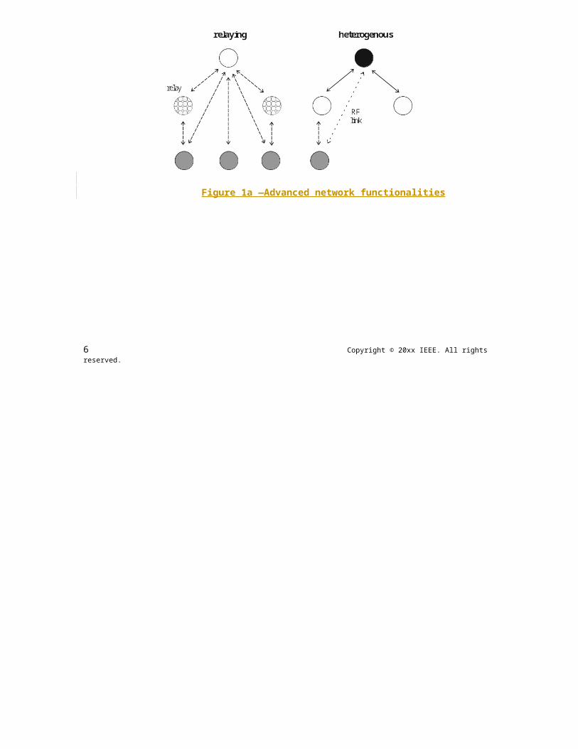
22 Copyright © 20xx IEEE. All rights reserved.

OPTICAL COMMUNICATION IEEE Std 802.15.7r1-20xx
If the originator does not receive an acknowledgment after some period, it assumes that the transmission was unsuccessful. When the acknowledgment is not required, the originator assumes the transmission was successful.
4.6.5.3 Data verification
A cyclic redundancy check is included in the MAC frame and the PHY header, as defined in Annex C, to verify the validity of the received data.
4.7 Security
From a security perspective, IEEE 802.15.7 VPAN is slightly different from other wireless networks, due to directionality and visibility because of the choice of the visible optical spectrum. Because of directionality and visibility, if an unauthorized receiver is in the path of the communication signal, it can be recognized. Also, the signal will not travel across medium such as walls, unlike other radio frequency based wireless networks. However, security algorithms are still provided in the standard for features such as data confidentiality, authentication and replay protection.
Devices can be low-cost and have limited capabilities in terms of computing power, available storage, and power drain; and it cannot always be assumed they have a trusted computing base nor a high-quality random number generator aboard. Communications cannot rely on the online availability of a fixed infrastructure and might involve short-term relationships between devices that may never have previously communicated. These constraints limit the choice of cryptographic algorithms and protocols and influence the design of the security architecture because the establishment and maintenance of trust relationships between devices need to be addressed with care. In addition, battery lifetime and cost constraints can put severe limits on the security overhead these networks can tolerate, something that is of far less concern with higher bandwidth networks. Most of these security architectural elements can be implemented at higher layers and may, therefore, be considered to be outside the scope of this standard.
The cryptographic mechanism in this standard is based on symmetric-key cryptography and uses keys that are provided by higher layer processes. The establishment and maintenance of these keys is outside the scope of this standard. The mechanism assumes a secure implementation of cryptographic operations and secure and authentic storage of keying material.
The cryptographic mechanism provides particular combinations of the following security services:
a) Data confidentiality: Assurance that transmitted information is only disclosed to parties for whom it is intended.
b) Data authenticity: Assurance of the source of transmitted information (and, thereby, that information was not modified in transit).
c) Replay protection: Assurance that duplicate information is detected.
The actual frame protection provided can be adapted on a frame-by-frame basis and allows for varying levels of data authenticity (to minimize security overhead in transmitted frames where required) and for optional data confidentiality. When nontrivial protection is required, replay protection is always provided.
Cryptographic frame protection is allowed to use a key shared between two peer devices (link key) or a key shared among a group of devices (group key), thus allowing some flexibility and application-specific trade-off between key storage and key maintenance costs versus the cryptographic protection provided. If a group key is used for peer-to-peer communication, protection is provided only against outsider devices and not against potential malicious devices in the key-sharing group.
The cryptographic security mechanisms used for protected MAC frames is described in Clause 8.
Copyright © 2011 IEEE. All rights reserved. 23
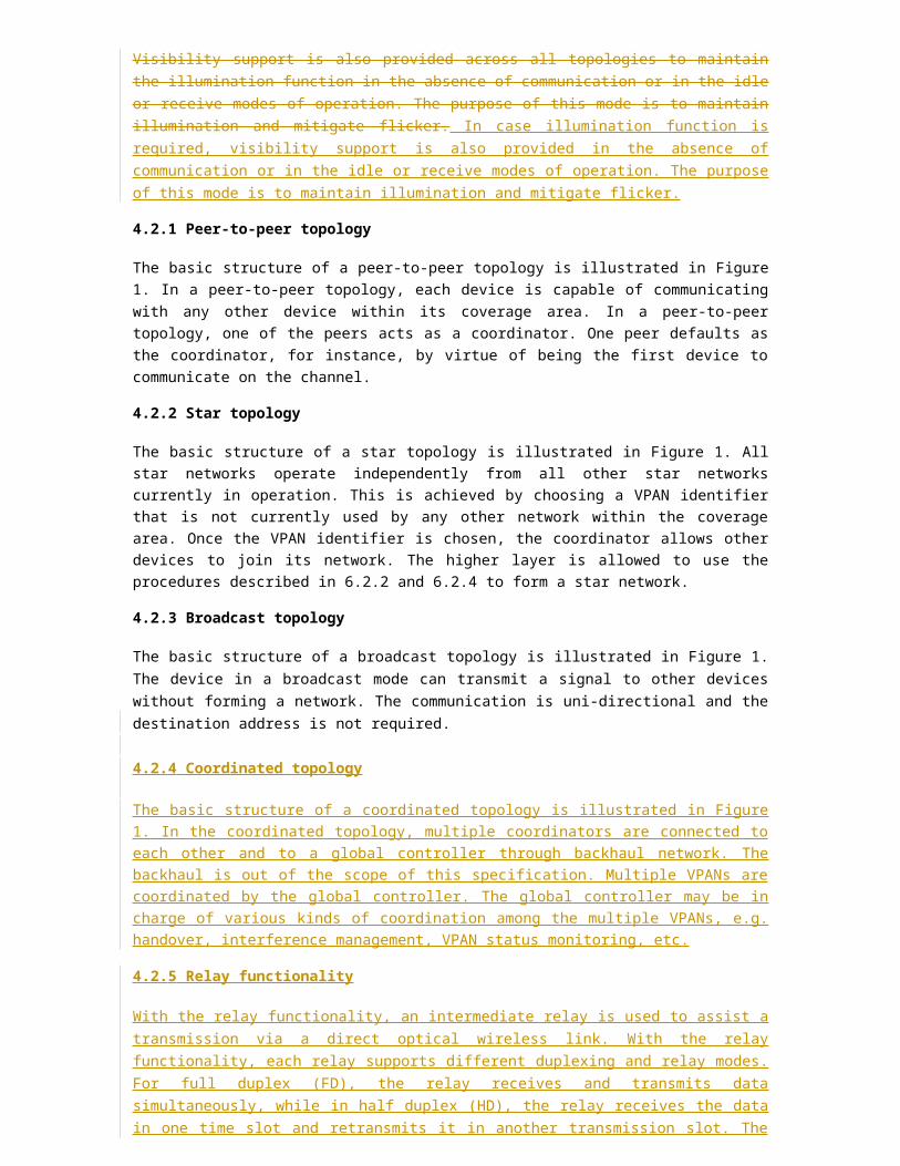
IEEE Std 802.15.7r1-20xx IEEE STANDARD FOR SHORT-RANGE WIRELESS
4.8 Concept of primitives
This subclause provides a brief overview of the concept of service primitives. The services of a layer are the capabilities it offers to the next higher layer or sublayer by building its functions on the services of the next lower layer. This concept is illustrated in Figure 15, showing the service hierarchy and the relationship of the two correspondent users and their associated layer (or sublayer) peer protocol entities.
Figure 15—Service primitives
The services are specified by describing the information flow between the user and the layer. This information flow is modeled by discrete, instantaneous events, which characterize the provision of a service. Each event consists of passing a service primitive from one layer to the other through a layer service access point (SAP) associated with an user. Service primitives convey the required information by providing a particular service. These service primitives are an abstraction because they specify only the provided service rather than the means by which it is provided. This definition is independent of any interface implementation.
Services are specified by describing the service primitives and parameters that characterize it. A service may have one or more related primitives that constitute the activity that is related to that particular service. Each service primitive may have zero or more parameters that convey the information required to provide the service.
A primitive can be one of the following four generic types:
a) Request: The request primitive is used to request a service to be initiated.b) Confirm: The confirm primitive is used to convey the results of one or more associated previous
service requests.c) Indication: The indication primitive is used to indicate the next higher layer of an internal event.d) Response: The response primitive is used to complete a procedure previously invoked by an
indication primitive.
5. Huawei MAC protocol specification
In this section, MAC specifications for different topologies, i.e. peer-to-peer, star, coordinated, are specified.
24 Copyright © 20xx IEEE. All rights reserved.
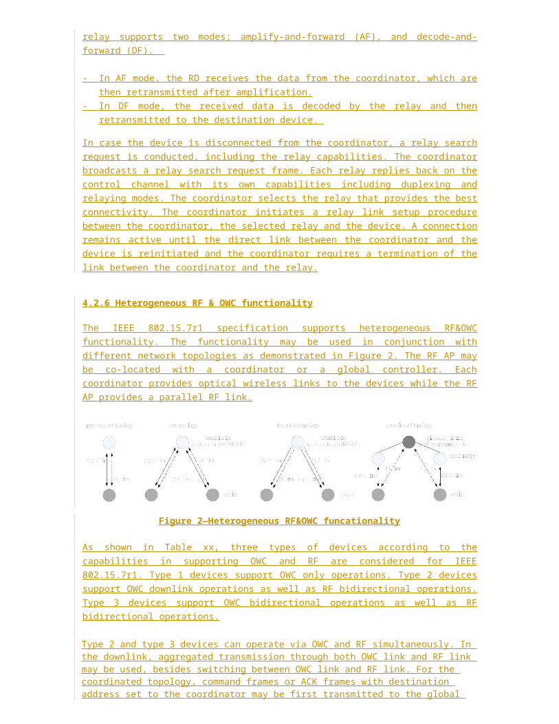
OPTICAL COMMUNICATION IEEE Std 802.15.7r1-20xx
5.1 Peer-to-peer
TBD
5.2 Star
5.2.1 Channel access
Both contention access and contention-free access are supported. Contention access is based on random access and shall be used for transmissions in CAP. Contention-free access is used for transmissions of bea-con frames as well as transmissions in CFP.
5.2.1.1 Channel access in CAP
CSMA/CA mechanism is used during the channel access in CAP, which supports prioritized access. To reduce the probability of collisions among contending devices, a random back- off algorithm is used to sepa-rate the timing that the different devices attempt to transmit. Prioritized access is achieved by assigning dif-ferentiated contention parameters to different access priorities, which allows frames associated with higher access priorities to win the contention with higher probabilities.
Since the coordinator and the devices in the VPAN may support different modulation bandwidths and the coordinator has no prior knowledge of which device will win during the contention in the CAP, it may not configure the receiver operating on a proper bandwidth to receive the uplink frames. In addition, the hidden node problems exist during the uplink communications in a VPAN. The coordinator shall adopt one of the following approaches to solve these issues.
Approach 1: The coordinator may divide the CAP into multiple regions according to the modula-tion bandwidths that the associated devices use. Each region is assigned to the transmissions that use a par-ticular modulation bandwidth.
Approach 2: The coordinator does not specify the allowed modulation bandwidth for the transmis-sions in the CAP in advance. In this case, an improved RTS/CTS mechanism shall be used in the CAP.
5.2.1.1.1 Approach 1
Since the coordinator records the supported modulation bandwidth of each associated device in its VPAN during association (see 9.5.1), it can determine the modulation bandwidth information of each associated device and divide the CAP into multiple regions and specify a bandwidth for each region according to the modulation bandwidth information. The bandwidth information can be the maximum bandwidth that each associated device supports, and the maximum bandwidth supported by the coordinator may also be consid-ered. For each region, only the transmissions of the signals that modulated on the specified bandwidth are allowed. The coordinator shall distribute the schedule of the CAP in the beacon frame, indicating a modula-tion bandwidth for each region respectively in the CAP descriptor subfield (see 9.2).
For each region, the RTS/CTS mechanism may be used in addition. The decisions on whether the RTS/CTS protocol should be used for each region is out of the scope of this standard. The coordinator shall indicate whether RTS/CTS protocol is used in the beacon frame (see 9.2).
A device shall transmit and receive in a particular region using the modulation bandwidth as indicated in the beacon frame, if Approach 1 is adopted. When a device in the VPAN that adopts Approach 1 attempts to transmit a frame, it shall locate the region that it is allowed to transmit according to the modulation band-widths it can support. If a device using a higher modulation bandwidth loses the contention of the channel, it
Copyright © 2011 IEEE. All rights reserved. 25

IEEE Std 802.15.7r1-20xx IEEE STANDARD FOR SHORT-RANGE WIRELESS
may switch to a lower modulation bandwidth and try to compete in the region that assigned to the transmis-sion using that modulation bandwidth.
At least one region for the transmission using the minimum modulation bandwidth shall be preserved, which can be used for the association of new devices.
The coordinator and a device shall set the operation modulation bandwidth according to the following rules:
The downlink PPDUs shall be modulated with the modulation bandwidth of min{max COODINATOR_Tx-_modulation_bandwidth, max DEVICE_Rx_modulation_bandwidth} , the PPDU carrying the correspond-ing ACK frames shall be modulated on the modulation bandwidth of min{max COODINATOR_Rx_modulation_bandwidth, max DEVICE_Tx_modulation_bandwidth} .
The uplink PPDUs shall be modulated on the modulation bandwidth lower than or equal to min{max COO-DINATOR_Rx_modulation_bandwidth, max DEVICE_Tx_modulation _bandwidth}, and the PPDU carry-ing the corresponding ACK frames shall be modulated on the modulation bandwidth min{max COODINATOR_Tx_modulation bandwidth, max DEVICE_Rx_modulation bandwidth}.
Both the coordinator and the devices shall receive with the modulation bandwidth indicated for each region.
If the coordinator indicates that the RTS/CTS protocol is used in a region of the CAP, transmission on uplink in this region shall use the RTS/CTS protocol. The RTS/CTS protocol should not be used for the downlink transmissions.
A device that gains the right for transmission after contention shall transmit an RTS frame prior to the trans-mission of the data/command frame. After receiving the RTS frame successfully, the coordinator shall trans-mit a CTS frame to the device that sourced the RTS frame. The device shall continue to transmit the data/ command frame only if it has received the corresponding CTS frame after the RTS frame it has sent.
If the device does not receive the CTS frames during [TBD ms] after it sent the RTS frame, it shall not trans-mit the data/command frame and shall try to compete to resend the RTS frame. Transmission of a frame sequence including a data/command frame with ACK using RTS/CTS is illustrated in Figure 8 1.
The RTS/CTS/ACK frames shall be transmitted using the modulation bandwidth that is indicated for the region by the coordinator.
Figure 16—An example of the usage of RTS/CTS
26 Copyright © 20xx IEEE. All rights reserved.
OPTICAL COMMUNICATION IEEE Std 802.15.7r1-20xx
5.2.1.1.2 Approach 2
Unlike approach 1, the coordinator may not divide the CAP into multiple regions and does not indicate a specific modulation bandwidth that can be used for the transmissions in the CAP. The coordinator shall indi-cate in the beacon if the following improved RTS/CTS protocol shall be used (see 9.2).
A device shall determine if the improved RTS/CTS protocol shall be used according to the beacon frames. If this improved RTS/CTS protocol shall be used, a device shall compete for the transmission of the RTS frame first. When the device gains the right for transmission after contention shall transmit an RTS frame. RTS is transmitted using the minimal bandwidth. The RTS frame shall include the modulation bandwidth, which can be used by the coordinator to determine the bandwidth for its receiver.
After receiving the RTS frame successfully, the coordinator shall transmit a CTS frame to the device that sourced the RTS frame. The coordinator shall record the modulation bandwidth that indicated in the received RTS frame, and use this modulation bandwidth to receive the following data/command frame.
The device shall continue to transmit the data/command frame using the modulation bandwidth indicated in previous RTS frame, only if it has received the corresponding CTS frame after the RTS frame it has sent. If the device does not receive the CTS frames during [TBD ms] after it sent the RTS frame, it shall not transmit the data/command frame and shall try to compete to resend the RTS frame. The coordinator may send an ACK frame following the data/command frame, if needed.
Transmission of a frame sequence including a data/command frame with ACK using RTS/CTS is presented in Figure 16.
In this improved RTS/CTS mechanism, the coordinator and a device shall set the operation modulation bandwidth according to the following rules:
The PPDU carrying a RTS/CTS/ACK frame shall be modulated on the minimum modulation band-width.
The PPDUs carrying data/command shall be modulated on the modulation bandwidth that is indi-cated in the RTS frame. The criteria for a device to determine this modulation bandwidth is out of the scope of this standard.
Both the coordinator and the devices shall be ready for receiving frames using the appropriate mod-ulation bandwidth.
For the downlink transmissions, the coordinator shall use the same RTS/CTS protocol described above except that the frames are modulated on the minimum bandwidth. Regarding the broadcast downlink trans-mission, the coordinator shall modulate the frames on the minimum bandwidth.
5.2.1.2 Channel access in CFP
The coordinator can divide the CFP of a superframe into multiple GTSs and assign them to itself or the asso-ciated devices that have traffic requiring guaranteed quality of service (QoS).
A device can request GTS allocations through flow establishment procedure, which is controlled by the coordinator (see TBD).
The coordinator shall inform the GTS allocations to devices in the beacon frame. Each GTS is described by at least one GTS descriptor (see TBD). The GTS descriptor indicates the length and position of the GTS and the device assigned to the GTS. The GTS descriptor may supply additional information, such as the subcar-
Copyright © 2011 IEEE. All rights reserved. 27

IEEE Std 802.15.7r1-20xx IEEE STANDARD FOR SHORT-RANGE WIRELESS
riers/frequencies/wavelengths that the device is allowed to use in the GTS, which can be used in the case that the interference coordination among neighboring VPANs (see TBD).
5.2.2 VPAN establishment
5.2.2.1 Scan procedure
A scan procedure shall be performed by a device or a prospective coordinator to detect any VPANs and coordinators that are operating in its vicinity. Three types of scanning are specified, i.e. passive scan, active scan and scan-over-backhaul.
Passive scan
Passive scan is performed by a devices before association. Passive scan is also performed by a prospective coordinator that plans to establish a VPAN if inter-coordinator communication over backhaul is infeasible.
During a passive scan, the MAC sublayer shall discard all frames received over the PHY data service that are not beacon frames.
A passive scan is requested by the next higher layer using the MLME-SCAN.request primitive (see TBD) with the ScanType parameter set to indicate a passive scan. On reception of the primitive, the MLME shall enable its receiver to receive beacon frames sent by other coordinators for ScanDuration. Every time when the MLME receives a beacon frame, it shall record the information contained in the unique beacon frame in a local neighboring VPAN descriptor list. A beacon frame is assumed unique if it contains both a VPAN ID and a source address that has not been seen before. When the scan is complete, the MLME shall report the VPAN descriptor list to the next higher layer by issuing a MLME-SCAN.confirm primitive (see TBD).
Active scan
An active scan allows a device to locate any coordinator transmitting beacon frames within its coverage area. It can be used by a device when it is requested by the coordinator to report a neighboring VPANs descriptors list.
During an active scan, the MAC sublayer shall process all frames rather than just the frames of its own VPAN.
An active scan is requested by the next higher layer using the MLME-SCAN.request primitive with the ScanType parameter set to indicate an active scan. On reception of the primitive, the MLME of the device shall generate a beacon request command (see TBD) and broadcast it. It shall enable its receiver to receive beacon frames sent by other coordinators for ScanDuration. If a coordinator of a peer-to-peer VPAN receives the beacon request, the coordinator shall transmit a beacon frame to the device as a response; if a coordinator of a star VPAN or coordinated VPAN receives the beacon request, it shall ignore it and continue transmitting its periodical beacons as usual.
When the MLME of the device receives a unique beacon frame, it shall update its local neighboring VPAN descriptor list based on the information contained in the unique beacon frame. A beacon frame shall be assumed to be unique if it contains both a VPAN ID and a source address that has not been seen before. When the ScanDuration time expires, the MLME of the device shall report the local neighboring VPAN descriptor list to the next higher layer by issuing a MLME-SCAN.confirm primitive.
Scan-over-backhaul
Scan-over-backhaul shall be performed by a prospective coordinator that plans to establish a VPAN if inter-coordinator communication over backhaul is feasible.
28 Copyright © 20xx IEEE. All rights reserved.
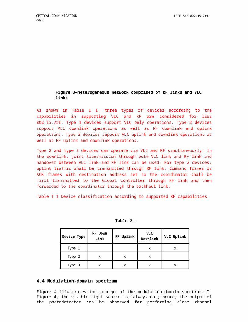
OPTICAL COMMUNICATION IEEE Std 802.15.7r1-20xx
Scan-over-backhaul is requested by the next higher layer of the prospective coordinator using the MLME-SCAN.request primitive with the ScanType parameter set to indicate a scan-over-backhaul, as defined in TBD. On reception of the primitive, the MLME of the prospective coordinator shall generate a scan-over-backhaul request command (see TBD) and send it to neighboring coordinators that are connected to the pro-spective coordinator through the backhaul. After the prospective coordinator transmitted the scan-over-backhaul request command, it shall enable its receiver (on the backhaul) to receive scan-over-backhaul con-firmation commands (as specified in TBD) sent by other coordinators for ScanDuration. Coordinators that have received the scan-over-backhaul request command through the backhaul shall respond with a scan-over-backhaul confirmation command, with its own VPAN descriptor embedded in it. When the MLME of the prospective coordinator receives a scan-over-backhaul confirmation command, it shall record the infor-mation contained in the unique scan -over-backhaul confirmation command in a local neighboring VPAN descriptor list. A scan-over- backhaul confirmation command frame shall be assumed to be unique if it con-tains both a VPAN ID and a source address that has not been seen before. When the ScanDuration time expires, the MLME of the prospective coordinator shall report the local neighboring VPAN descriptor list to the next higher layer by issuing a MLME-SCAN.confirm primitive.
5.2.2.2 Establish a VPAN
A prospective coordinator shall perform the following procedures to establish a VPAN.
On receipt of the primitive MLME-RESET.request (see TBD), the MLME of the prospective coordinator shall turn off the transceiver by issuing a PLME-SET-TRX-STATE.request to the PHY layer, and then the MAC sublayer is set to its initial conditions, clearing all internal variables to their default values.
The MLME of the device shall respond with a MLME-RESET.confirm primitive (see TBD) to notify the next higher layer the result of the reset operation.
After the reset, the next higher layer of the prospective coordinator shall issue a MLME-SCAN.request primitive (see TBD) to require the MLME to perform a scan to discover other VPANs in its vicinity. Two types of scan may be performed. If inter-coordinator communication over backhaul is feasible, then a scan-over-backhaul is performed. Otherwise, a passive scan shall be performed. The specific scan type shall be indicated by the next higher layer in the MLME -SCAN.request primitive. After the requested scan is done, the MLME shall issue a MLME-SCAN.confirm primitive (see TBD) to report the result of the scan.
The next higher layer of the prospective coordinator shall select a VPAN ID and the short address of the coordinator based on the VPAN IDs and the short addresses recorded in the local neighboring VPANs descriptor list obtained via the scan once it has received the MLME-SCAN.confirm. The MLME of the pro-spective coordinator shall select a VPAN ID and short address that are different from the VPAN IDs and short addressed obtained via the scan. Then the next higher layer shall provide the selected VPAN ID and short address to the MLME by issuing a MLME-START.request primitive (see TBD).
On receipt of the MLME-START.request, the MLME of the prospective coordinator shall start a superframe and broadcast beacon frames with the selected parameters (e.g., VPAN ID, short address) periodically.
Copyright © 2011 IEEE. All rights reserved. 29
IEEE Std 802.15.7r1-20xx IEEE STANDARD FOR SHORT-RANGE WIRELESS
Figure 17—VPAN establishment procedure
5.2.3 Association and disassociation
0Association.0.0.1IEEE802.15.7-2011 Superframe
5.2.3.1 Association
A device shall perform a passive scan procedure (see TBD) after it is powered on. The results of the channel scan would have then been used for choosing a suitable VPAN. The algorithm for selecting a suitable VPAN with which to associate from the neighboring VPANs descriptor list returned from the passive scan proce-dure is out of the scope of this standard.
Following the selection of a VPAN with which to associate, the next higher layers shall request through the MLME- ASSOCIATE.request primitive (see TBD) that the MLME configures the PHY and MAC PIB attri-butes to the values necessary for association.
A coordinator shall allow association only if macAssociationPermit is set to TRUE. Similarly, a device should attempt to associate only with a VPAN through a coordinator that is currently allowing association, as indicated in the results of the scanning procedure. If a coordinator with macAssociationPermit set to FALSE receives an association request command from a device, the command shall be rejected.
The MAC sub-layer of an unassociated device shall initiate the association procedure by sending an associa-tion request command (see TBD) to the coordinator of an existing VPAN.
Upon the reception of the association request command, the coordinator shall determine if it will accept the association request and reply an association response command (see TBD) to the device within [TBD ms]. The coordinator shall indicate if it accepts the request in the association response command. If the the request is accepted, a unique short address is assigned for the device in the association response command.
If the device does not receive the association response command [TBD ms] after it sent the association request command, it shall resend the request. The maximal retry times is [4].
During the association process, the PPDU carrying the association request command and the association response command and the corresponding ACK frames shall be modulated using the minimum bandwidth and be sent in the CAP following the channel access rules as described in TBD. The device and the coordi-nator can exchange the capabilities information via the association process, such as the modulation band-widths a device can support.
30 Copyright © 20xx IEEE. All rights reserved.
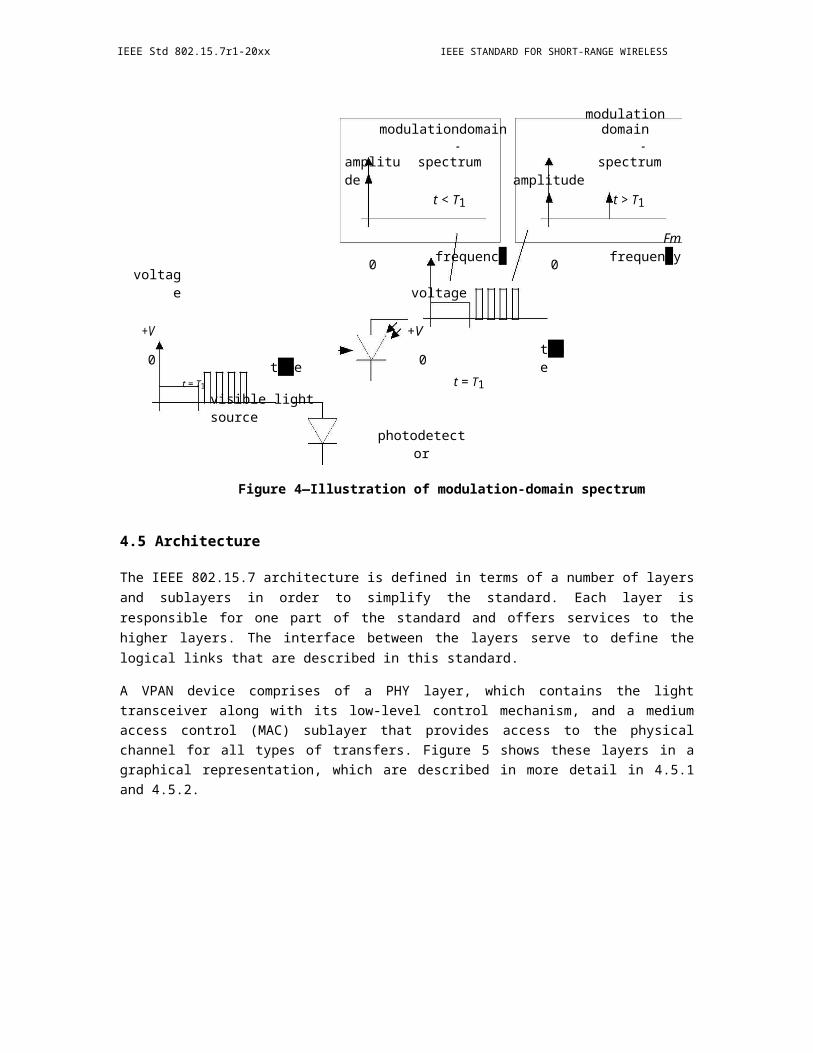
OPTICAL COMMUNICATION IEEE Std 802.15.7r1-20xx
5.2.3.2 Disassociation
The disassociation procedure is initiated by the next higher layer by issuing the MLME-DISASSOCI-ATE.request primitive (see TBD) to the MLME.
When a coordinator wants one of its associated devices to leave the VPAN, the coordinator shall send a dis-association notification command frame (see TBD) to the device. The device shall reply a disassociation response command frame (see TBD) to the coordinator within [TBD ms].
If an associated device wants to leave the VPAN, the MLME of the device shall send a disassociation notifi-cation command frame to the coordinator. The coordinator shall reply a disassociation response command frame to the device within [TBD ms].
After the device disassociated from the VPAN, the coordinator shall release the short address, the Flow_IDs, GTS allocations that has been assigned to the device.
5.2.4 VPAN Maintenance
5.2.4.1 VPAN ID conflict
In some instances a situation could occur in which two VPANs exist in the same operating space are with the same VPAN ID. If this conflict happens, the coordinator and its devices shall perform the VPAN ID conflict resolution procedure.
5.2.4.1.1 VPAN ID conflict detection
The VPAN coordinator shall conclude that a VPAN ID conflict is present if either of the following applies:
A beacon frame is received by the VPAN coordinator with the VPAN coordinator subfield set to one and the VPAN ID equal to macVPANId
A VPAN ID conflict notification command (see 9.5.11) is received by the VPAN coordinator from an associated device on its VPAN.
A device that is associated through the VPAN coordinator shall conclude that a VPAN ID conflict is present if the following applies;
A beacon frame is received by the device with the VPAN coordinator subfield set to one, the VPAN ID equal to macVPANId, and an address that is equal to neither macCoordShortAddress nor macCoordEx-tendedAddress.
5.2.4.1.2 VPAN ID conflict resolution
On the detection of a VPAN ID conflict by a device, it shall generate the VPAN ID conflict notification com-mand (see TBD) and send it to its coordinator. The coordinator shall confirm its reception by sending an ACK frame. Once the device has received the ACK frame from the coordinator, the MLME shall issue an MLME-SYNC -LOSS.indication primitive (see TBD) with the LossReason parameter set to VPAN_ID_-CONFLICT. If the device does not receive an ACK frame, the MLME shall not inform the next higher layer of the VPAN ID conflict.
Copyright © 2011 IEEE. All rights reserved. 31

IEEE Std 802.15.7r1-20xx IEEE STANDARD FOR SHORT-RANGE WIRELESS
On reception of the VPAN ID conflict notification command by the coordinator, the coordinator is notified of the VPAN ID conflict and the MLME shall issue an MLME-SYNC-LOSS.indication to its next higher layer with the LossReason parameter set to VPAN_ID_CONFLICT.
On receipt of the MLME-SYNC- LOSS.indication primitive with the LossReason parameter set to VPAN_ID_CONFLICT by the next higher layer of the coordinator, it may issue a MLME-NeighborRe-port.request primitive (see TBD) to its MLME to trigger a neighboring VPAN report.
On receipt of the MLME- NeighborReport.request primitive, the MLME of the coordinator shall generate a neighboring VPAN report request command (see TBD) and send it to the device(s) indicated in the Report-DevicesList of the MLME-NeighborVPANReport.request primitive. To which device(s) the neighboring VPAN request command shall be sent is determined by the next higher layer and is out of the scope of the specification. Then the coordinator shall wait for the neighboring VPAN report indication commands (see TBD) sent by the devices for [TBD ms].
Devices that have received the neighboring VPAN report request command from the coordinator may first perform an active scan. The device updates its local neighboring VPAN descriptors list according to the result obtained from the active scan. When the active scan requested by the coordinator is done, the device shall generate a neighboring VPAN report indication command based on its updated local neighboring VPAN descriptor list and send the neighboring VPAN report indication command to the coordinator.
If the device choose not to perform the active scan after it receives the neighboring VPAN report request command, it shall generate a neighboring VPAN report indication command which include its local neigh-boring VPAN descriptor list and send the command to the coordinator.
When the coordinator has received a unique neighboring VPAN report indication command from the device, it shall update its global neighboring VPAN descriptor list. When [TBD ms] elapsed, the MLME of the coor-dinator shall notify its next higher layer the result of the requested neighboring VPAN report by issuing a MLME-NeighborReport.confirm primitive (see TBD). The next higher layer of the coordinator shall select a new VPAN ID based on the VPAN IDs recorded in its updated global neighboring VPAN descriptor list. The MLME of the coordinator shall select a new VPAN ID that is different from the VPAN IDs that are recorded in its updated global neighboring VPAN descriptor list. The next higher layer of the coordinator shall pro-vide the new VPAN ID to its MLME by issuing a MLME- START.request primitive with the CoordRealign-ment parameter set to TRUE. The MLME shall perform a VPAN realignment on receipt of the MLME-START.request primitive with the CoordRealignment parameter set to TRUE.
5.2.4.2 VPAN realignment
A coordinator shall generate a coordinator realignment command (see TBD) on reception of a MLME-START.request primitive (see TBD) with the CoordRealignment parameter set to TRUE. The coordinator shall broadcast the coordinator realignment command containing the new VPAN parameters (e.g., the selected VPAN ID) and the effective time. When a device receives the coordinator realignment command, the MLME of the device shall notify its next higher layer the VPAN realignment by issuing a MLME-SYNC-LOSS.indication primitive (see TBD).
The coordinator realignment command shall indicate in which superframe the new parameters will take effect by setting a proper value to the Effective Time field. The coordinator shall also indicate it by setting the CountDown field in the following beacon frames (see TBD) . Both the coordinator and devices shall make sure the new parameters are properly set and start to use the new parameters (e.g., the selected VPAN ID) when the effective time comes. The coordinator and the devices shall set the new parameters by issuing a MLME-SET.request primitive (see TBD) to the MLME from the next higher layer.
32 Copyright © 20xx IEEE. All rights reserved.
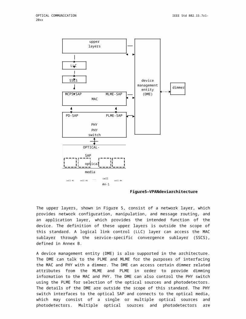
OPTICAL COMMUNICATION IEEE Std 802.15.7r1-20xx
5.2.5 Neighboring VPAN status monitoring
Neighboring VPANs status monitoring procedure allows the coordinator and the devices to detect and main-tain neighboring VPANs information. Neighboring VPAN status monitoring maybe performed for the pur-poses of VPAN maintenance, interference coordination and handover.
Both coordinators and the devices shall participate in the neighboring VPANs status monitoring procedure.
The information of neighboring VPANs that can be detected shall be recorded in a neighboring VPANs descriptor list.
Both the coordinator and the devices shall each maintain a local neighboring VPANs descriptor list respec-tively. The local neighboring VPAN descriptor list is shown in Table TBD. The local neighboring VPAN descriptor list is maintained by receiving beacon frames or other frames from the neighboring VPANs. When a beacon frame or any other frame from neighboring VPANs is received for the first time, a new record corresponding to the neighboring VPAN shall be added to the list. The record in the list has an ageing time of [TBD] ms. Whenever a beacon frame or any other frame from a neighboring VPAN corresponding to a record in the list has been received, the device shall update the LastTimeDetected of the record instead of adding a new record. Once the beacon frames or any other frame from a neighboring VPAN correspond-ing to a record in the list has not been received within the ageing time since last time it was detected, the record corresponding to that neighboring VPAN shall be deleted from the list.
Insert Table 8-1 Local neighboring VPANs descriptor list here (16/360r0)
Insert Table 8-2 the format of the VPAN descriptor here (16/360r0)
The devices shall update their local neighboring VPANs descriptor list and send a neighboring VPAN report indication command (see TBD) to the coordinator to report its local neighboring VPANs descriptor list whenever any of the following events occurs:
It has received a beacon frame or any other frames sent by the neighboring coordinators or devices for the first time;
It has been [TBD] superframes since the neighboring VPAN was detected last time;
A neighboring VPAN report request command (see TBD) is received by the device from the coor-dinator;
The coordinator shall update its local neighboring VPAN descriptor list whenever any of the following events occurs:
It has received a beacon frame or any other frames sent by the neighboring coordinators or devices for the first time;
It has been [TBD] superframes since the neighboring VPAN was detected last time;
The coordinator shall also maintain a global neighboring VPAN descriptor list. The global neighboring VPAN descriptor list is maintained and updated by gathering the reported local neighboring VPAN descrip-tor lists from devices and its own local neighboring VPAN descriptor list. The global neighboring VPANs descriptor list is shown in Table TBD.
The coordinator shall update its global neighboring VPAN descriptors list whenever it has received a neigh-boring VPAN report indication command from devices in the VPAN, or when its own local neighboring VPAN descriptors list has been updated. The coordinator shall also update the global neighboring VPAN
Copyright © 2011 IEEE. All rights reserved. 33
IEEE Std 802.15.7r1-20xx IEEE STANDARD FOR SHORT-RANGE WIRELESS
descriptors list by deleting the corresponding information if the device which has reported the corresponding information is disassociated from the VPAN.
Insert Table 8-3 Global neighboring VPANs descriptor list here (16/360r0)
5.2.6 GTS allocation and management
A GTS allows a device to operate on the channel within a portion of the superframe that is dedicated (on the VPAN) exclusively to that device. A GTS shall be allocated only by the coordinator, and it shall be used only for communications between the coordinator and a device associated with the VPAN through the coor-dinator. A single GTS may extend over one or more superframe slots. The coordinator may allocate a num-ber of GTSs at the same time, provided there is sufficient capacity in the superframe.
One or more flows can be setup between the coordinator and a device, the flows can be either downlink or uplink. The allocated GTSs for a flow should meet the QoS constraints specified in the TSpec (see TBD). The way in which the coordinator manages the available resources and the particular schedules it generates are out the scope of this standard. The scheduling of GTS is indicated by the coordinator in the beacon frame.
The TSpec describes the set of parameters that define the characteristics and QoS expectations of a particu-lar flow.
5.2.6.1 Flow establishment
A flow can be originated by a coordinator or a device. The originator shall send a flow establishment request command (see TBD) to the recipient to establish a flow. The recipient shall reply a flow establishment response command (see TBD) to the originator to notify if it accepts the flow establishment request. Both the coordinator and a device can originate a bidirectional flow, in this case, the TSpec of the reverse flow shall be included in the flow establishment response command.
When a coordinator originates a flow, it shall reserve sufficient resources for the flow before it sends the flow establishment request to the recipient device. When a coordinator receives a flow establishment request from a device, it shall first check if there is sufficient resource to meet the QoS requirements. If it accepts the request, it shall reserve sufficient resources for the flow and assign a GTS for this flow. If the coordinator denies the request from a device means that no QoS guarantees can be given, the medium access may still be performed on a priority-basis in the CAP.
The coordinator shall assign a unique Flow_ID for each flow in the VPAN. In case of the bi-directional flow, the coordinator shall assign different Flow_IDs for the forward and reverse flows respectively.
Figure 18—Flow establishment procedure
34 Copyright © 20xx IEEE. All rights reserved.
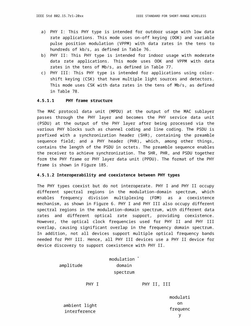
OPTICAL COMMUNICATION IEEE Std 802.15.7r1-20xx
5.2.6.2 Flow maintenance
The coordinator can monitor the status of the link between a device and itself. The uplink channel status can be measured by the coordinator while the downlink channel status through the CSI feedback mechanism (see TBD). The coordinator may change the flow parameters by sending a flow modify request command (see TBD) to the device if it decides that the TSpec of the current flow cannot be supported. The device can transmit a flow modify response command (see TBD) to the coordinator indicating whether the offered flow parameters can be accepted or not.
If the coordinator changes the GTS allocation for a flow, the new allocation for the flow will be conveyed in the following beacons.
5.2.6.3 Flow termination
If the originator of a flow decides that the flow is required to be released, it shall send a flow terminate request command (see TBD) to the recipient. The recipient shall reply a flow terminate response command (see TBD) to the originator. The coordinator shall then stop assigning the GTS allocations for the flow.
Figure 19—Flow termination procedure
5.2.7 Acknowledgment and retransmission
Both Transmissions with acknowledgement or without acknowledgement are supported. The next higher layer shall provide the indication whether acknowledgement is required or not when issuing the MCPS-DATA.request primitive (see TBD) to the MAC sublayer. All MAC command frame shall be transmitted with acknowledgement. All broadcast frames, e.g., beacons, shall be transmitted without acknowledgement.
When ACK is not required, the transmission is always assumed to be successful.
If ACK frame is not received or an ACK frame is received with an error when ACK is required, then the device shall conclude the transmission has failed and retransmission is needed.
5.2.8 CSI feedback and link adaptation
5.2.8.1 CSI feedback with MCS suggestion
The CSI responder may use CSI feedback with MCS suggestion to indicate a suggested MCS level to the CSI requester. Link adaptation control subfield in the MHR (see TBD) can be used to request CSI feedback or provide suggest MCS level.
Both solicited feedback and unsolicited feedback are supported.
Copyright © 2011 IEEE. All rights reserved. 35
IEEE Std 802.15.7r1-20xx IEEE STANDARD FOR SHORT-RANGE WIRELESS
Solicited feedback: a CSI requester request a CSI responder to feedback CSI.
Unsolicited feedback: a coordinator/device report CSI to another device/coordinator without arequest.
For solicited feedback, the CSI requester may set the MCS request field in link adaptation control subfield to '0b1' to request a responder to provide MCS recommendation. In each MCS request, the requester shall set the MSI (MCS sequence index) subfield in the link adaptation control field to a value in the range 0 to 6. How the requester chooses the MSI value is implementation dependent.
On receipt of a frame with the MCS request subfield equal to '0b1', a CSI responder initiates computation of the MCS estimate and labels the result of this computation with the MSI value. The MFB responder includes the received MSI value in the feedback sequence index field of the corresponding response frame. The sug-gested MCS level is transmitted in MCS feedback field.
For unsolicited feedback, a device/coordinator feedbacks a suggested MCS level without being requested. In this case, feedback sequence index is set to '0b111', and suggested MCS level is transmitted in MCS feed-back field.
After CSI feedback is obtained by the transmitter, it selects a MCS level for future transmissions. The selected MCS level may or may not be the one suggested by the receiver.
The selected MCS level for data transmission is indicated in PHY header.
5.2.8.2 CSI feedback for bit-loading
TBD
5.2.8.3 CSI feedback for MIMO operation
TBD
5.2.9 Interference coordination
TBD
5.2.10 Mobility and handover
TBD
5.3 Coordinated
5.3.1 Channel access
Same as TBD.
5.3.2 VPAN establishment
When the prospective coordinator is turned on, it should try to determine whether it is connected to a global controller through the backhaul link. The specific protocol for the prospective coordinator to detect the global controller through the backhaul link is out of the scope of this specification. If the global controller has been detected through the backhaul, the next higher layer of the prospective coordinator shall start a VPAN in the coordinated mode. If the global controller has not been detected through the backhaul, the next
36 Copyright © 20xx IEEE. All rights reserved.

OPTICAL COMMUNICATION IEEE Std 802.15.7r1-20xx
higher layer of the prospective coordinator shall start a VPAN in star mode, which has been specified in clause TBD.
The prospective coordinator shall perform the following procedures to start a VPAN in the coordinated mode.
Once the prospective coordinator detects the presence of the global controller through the backhaul link, it shall exchange messages with the global controller to obtain all the necessary parameters (e.g., the VPAN ID, the short address of the coordinator, etc.) to start a VPAN. The global controller shall provide the param-eters to the prospective coordinator through the message exchanges. These messages exchanged between the prospective coordinator and the global controller shall be transmitted through the backhaul link and are out of the scope of the specification.
Once the prospective coordinator has obtained the parameters from the global controller, it shall reset the MAC sublayer and PHY layer. The next higher layer of the prospective coordinator shall issue a MLME-RESET.request primitive (see TBD) to its MLME. On receipt of the primitive MLME-RESET.request, the MLME of the prospective coordinator shall turn off the transceiver by issuing a PLME-SET- TRX-STATE.request to the PHY layer, and then the MAC sublayer is set to its initial conditions, clearing all inter-nal variables to their default values.
The MLME of the prospective coordinator shall respond with a MLME-RESET.confirm primitive (see TBD) to notify its next higher layer the result of the reset operation.
The next higher layer of prospective coordinator shall issue a MLME-START.request primitive (see TBD) to its MLME on receipt of the MLME-RESET.confirm primitive (see TBD). The next higher layer of the pro-spective coordinator shall provide the necessary parameters (e.g., the VPAN ID, the short address of the coordinator, etc.) to its MLME through the MLME-START.request primitive. On receipt of the MLME-START.request, the MLME shall start to broadcast beacon frame periodically and a VPAN is established.
5.3.3 Association and disassociation
5.3.3.1 Association
A device shall perform a passive scan procedure (see TBD) after it is powered on.
If no VPAN is detected, the next higher layer of the device may request the MLME to send an additional beacon request command (see TBD). After sending the additional beacon request command, the device shall continue to scan the channel to discover beacon frames or additional beacon frames during Tcoordscan. If the device cannot detect any beacon when the Tcoordscan expires, it may attempt to send another additional beacon request command.
The device that detects beacon frames during either the passive scan period or the continued Tcoordscan, shall attempt to associate to a coordinator by sending association request command (see TBD). The results of the scan would have then been used for choosing a suitable VPAN. The algorithm for selecting a suitable VPAN with which to associate from the VPAN descriptors list returned from the scan procedure is out of the scope of this standard.
Following the selection of a VPAN with which to associate, the next higher layers shall request through the MLME- ASSOCIATE.request primitive (see TBD) that the MLME configures the PHY and MAC PIB attri-butes to the values necessary for association. The device shall indicate in the type of the beacon that triggers the association request of the device in the association request command.
A coordinator shall allow association only if macAssociationPermit is set to TRUE. Similarly, a device should attempt to associate only with a VPAN through a coordinator that is currently allowing association,
Copyright © 2011 IEEE. All rights reserved. 37

IEEE Std 802.15.7r1-20xx IEEE STANDARD FOR SHORT-RANGE WIRELESS
as indicated in the results of the scanning. If a coordinator with macAssociationPermit set to FALSE receives an association request command from a device, the command shall be rejected.
The MAC sub-layer of an unassociated device shall initiate the association procedure by sending an associa-tion request command to the coordinator of an existing VPAN. If the device does not receive the association response command after [TBD ms] it sent the association request command, it shall resend the request. The maximal retry times is 4.
A coordinator receives the additional beacon request commands from a device may start to send additional beacons in each superframe from the next superframe in addition to the original beacons. The coordinator shall allocate a GTS in the CFP to transmit the additional beacon frames. The content of the additional bea-con frame shall be the same as the beacon sent in the BP in the same superframe except the beacon type and shall be modulated on the minimum bandwidth. The BeaconType field in the beacon frame can be used to identify the type of the beacons. If the coordinator receives another additional beacon request command from the same device, it may allocate a different GTS to transmit in the CFP to transmit additional beacon frames from the next superframe. If the coordinator receives an association request from the device that sent the additional beacon request command within [TBD ms], it shall handle the association request. If the coor-dinator does not receive any association request from the device that sent the additional beacon request com-mand within [TBD ms], it may stop transmit the additional beacons and only transmit the original beacons.
Upon the reception of the association request command, the coordinator shall determine if the association request will be accepted and reply an association response command to the device within [TBD ms]. The coordinator shall indicate if it accepts the request in the association response command, and if it denies the request, it shall also indicate the reason. If the coordinator accepts the request, it shall assign a unique short address for the device and include it in the association response command.
If the received association request indicates that the request is sent based on the detection of only additional beacons, the coordinator may also infer that interference occurs between its VPAN and one or multiple neighboring VPANs, and execute the interference coordination. The Interference Info field included in the association request command can be used for the interference coordination. If the coordinator receives any association request indicating the request is based on the detection of original beacons, interference coordi-nation is not needed for this device.
During the association process, the PPDU carrying the association request command and the association response command and the corresponding ACK frames shall be modulated using the minimum bandwidth and be sent in the CAP following the channel access rules as described in TBD. The device and the coordi-nator can exchange the capabilities information via the association process, such as the modulation band-widths a device can support.
5.3.3.2 Disassociation
Same as TBD.
5.3.4 VPAN Maintenance
5.3.4.1 VPAN ID conflict
In some instances a situation could occur in which two VPANs exist in the same operating space with the same VPAN ID. If this conflict happens, the coordinator and its devices shall perform the VPAN ID conflict resolution procedure.
5.3.4.1.1 VPAN ID conflict detection
Same as 8.2.4.1.1.
38 Copyright © 20xx IEEE. All rights reserved.
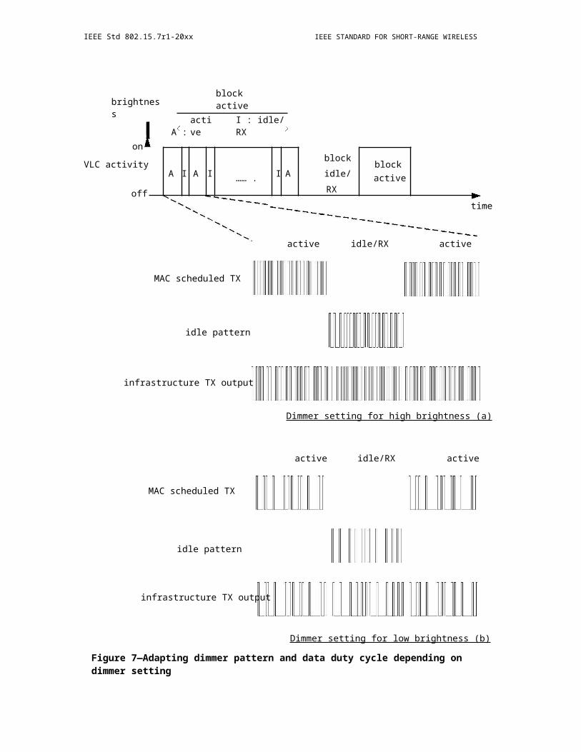
OPTICAL COMMUNICATION IEEE Std 802.15.7r1-20xx
5.3.4.1.2 VPAN ID conflict resolution
Same as 8.2.4.1.2.
5.3.5 Neighboring VPAN status monitoring
Same as 0.
5.3.6 GTS allocation and management
5.3.6.1 Flow establishment
Same as 8.2.6.1.
5.3.6.2 Flow maintenance
Same as 8.2.6.2.
5.3.6.3 Flow termination
Same as 8.2.6.3.
5.3.7 Acknowledgement and retransmission
Same as 8.2.7.
5.3.8 CSI feedback and link adaptation
5.3.8.1 CSI feedback with MCS suggestion
Same as 8.2.8.1.
5.3.8.2 CSI feedback for bit-loading
TBD
5.3.8.3 CSI feedback for MIMO operation
TBD
5.3.9 Interference coordination
5.3.9.1 General description
The VPANs managed by the same global controller (GC) forms a VPAN cluster. In this clause, only intra-cluster interference coordination are specified.
At the beginning of the VPAN establishment, the boundary of the superframe of all the VPANs in the same cluster should be aligned, and different VPANs may use the same beacon slot for beacon frame transmission.
A device and the coordinator should be capable of detecting the presence of other neighboring VPANs that have the overlapped coverage with the VPAN it associated with. The coordinator is responsible for collect-
Copyright © 2011 IEEE. All rights reserved. 39

IEEE Std 802.15.7r1-20xx IEEE STANDARD FOR SHORT-RANGE WIRELESS
ing the interference information from all devices associated with it and report to the global controller. The coordinator should be capable of receive the resource coordination information from the global controller, which will be used for scheduling the allocations in the superframe.
The interference coordination is executed based on the coordination period. The interference information that is reported in current coordination period should be used for the resource coordination during next coor-dination period. The duration of a coordination period Tcoordination shall equal to the length of [TBD] superframe.
The interference coordination procedure includes the following mechanisms.
Interference measurement and report
Resource coordination
Interference parameters/resource coordination update
5.3.9.2 Interference measurement and report
The interference measurement and report shall follow the Neighboring VPANs status monitoring procedure specified in 0.
The coordinator shall report the interference information to the global controller every [TBD] superframes (i.e., a coordination period). The value of the coordination period can be determined by the global controller.
5.3.9.3 Resource Coordination
The resource coordination shall be executed for both BP and non-BP (i.e, CAP and CFP) by the global con-troller according to the interference information received from the coordinators. For the BP, the global con-troller shall coordinate the transmissions of beacons in a TDM manner and allocate different beacon slots for the VPANs that interfere with each other. The structure of the beacon period of a VPAN refers to section 7. For the non-BP part, the global controller may coordinate the resources in TDM/WDM/FDM manners, which is vendor discretionary. Other rules and criteria for resource coordination is out of the scope of this standard.
The global controller allocates resources for the VPANs that it manages and notify the coordinators about the allocations. The coordinator that does not receive the allocations information from the global controller can makes the scheduling by itself; the coordinator that receive the allocations information from the network controller shall take the allocation information into account for scheduling.
5.3.9.4 Interference coordination update
Both the device and the coordinator shall be capable of updating the interference information. The coordina-tor shall update the global record of neighboring VPANs according to the reports from the associated devices and its detection of neighboring VPANs (see 0). The coordinator shall report the updated interference infor-mation to the global controller for the coordination in the next coordination period. The global controller shall then update the resource coordination using the latest interference information.
40 Copyright © 20xx IEEE. All rights reserved.

OPTICAL COMMUNICATION IEEE Std 802.15.7r1-20xx
Figure 20—An example of the interference coordination
5.3.10 Mobility and handover
Handover is used when a device moves from the coverage of one VPAN to other. Two types of handover procedures are specified,
Type 1: handover initiated by device
Type 2: handover initiated by global controller
5.3.10.1 Type 1: handover initiated by device
After association to a VPAN, a device may search the area for available neighboring coordinators and per-form received signal strength (RSS) measurement. The measurement is based on beacons or reference sig-nals.
A device may perform alpha-filtering on the measurements based on
RSS_n=(1-?) RSS_(n-1)+?M_n
Where M_n is the latest received measurement result from the physical layer; RSS_n is the updated filtered measurement result, that is used for evaluation of reporting criteria or for measurement reporting; RSS_(n-1) is the old filtered measurement result; ? is a filtering-coefficient that can be configured.
If the RSS of neighbor cells satisfy
RSS_(n,target)-RSS_(n,associate)>?_th1
Then the device should initiate the handover to the target coordinator. Here RSS_target is the RSS of the tar-get coordinator and RSS_associate is the RSS of the associated coordinator and ?_th1 is a predefined thresh-old.
Once the handover is initiated by the device, it sends a re-association request command (see 9.5.3) to the tar-get coordinator. The device uses the re-association request to request association as well as to send its pre-ferred QoS requirements to the target coordinator.
In the reassociation response command (see 9.5.4), the target coordinator indicates whether the request is permitted. Besides, the target coordinator also inform the QoS resources allocated to the device, or suggests alternate level of QoS the target coordinator can support.
Copyright © 2011 IEEE. All rights reserved. 41
IEEE Std 802.15.7r1-20xx IEEE STANDARD FOR SHORT-RANGE WIRELESS
The previous coordinator may continue to send the packets that have been store in the buffer to the device. The device may receive these packets to its best effort. If the previous coordinator does not received acknowledgement from the device for N consecutive frames, then the previous coordinator consider the device has left the VPAN and the transmission is ceased.
Figure 21—Handover initiated by device
5.3.10.2 Type 2: handover initiated by global controller
After association to a VPAN, a device may scan the area for available neighboring coordinators and perform received signal strength (RSS) measurement. The measurement is based on beacons or reference signals.
A device may perform alpha-filtering on the measurements based on
RSS_n=(1-?) RSS_(n-1)+?M_n
Where M_n is the latest received measurement result from the physical layer; RSS_n is the updated filtered measurement result, that is used for evaluation of reporting criteria or for measurement reporting; RSS_(n-1) is the old filtered measurement result; ? is a filtering-coefficient that can be configured.
The device may report the measured RSS of neighboring VPANs to the coordinator using the procedure described in TBD.
The coordinator can send the measurement report to the global controller together with the QoS requirement of the device. If the global controller decides to handover the device to the target coordinator, it sends its decision to the current coordinator. It also notify the target coordinator about the upcoming handover together with QoS requirement. The procedures for the communications between global controller and the coordinator are out the scope of this specification.
Current coordinator sends handover command frame to the device.
Then the device sends re-association request (see TBD) to the target device.
In the re-association response command, the target coordinator confirms the handover. Besides, the target coordinator also informs the QoS resources allocated to the device, or suggests alternate level of QoS the target coordinator can support.
42 Copyright © 20xx IEEE. All rights reserved.
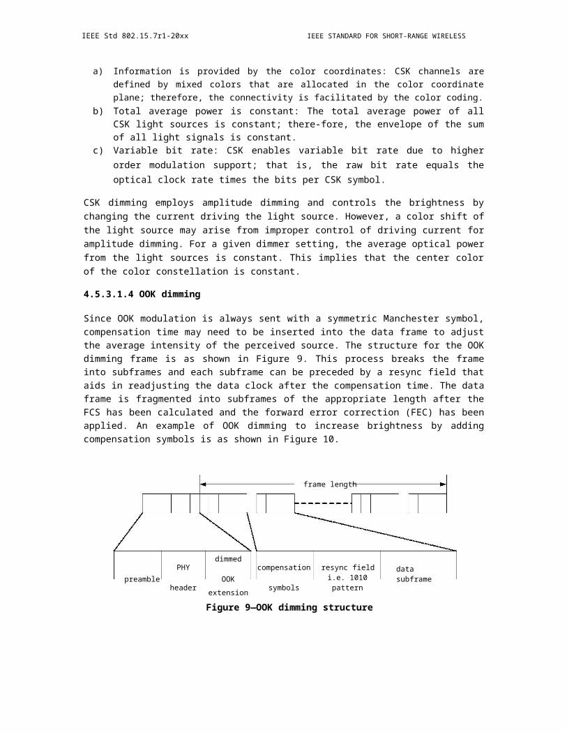
OPTICAL COMMUNICATION IEEE Std 802.15.7r1-20xx
Figure 22—Handover initiated by global controller
5.4 MAC frame formats
The MAC frame format is composed of a MHR, a MSDU and a MFR. The specific fields of each component is for further study.
Five frame types are defined: beacon, data, ACK, command and control.
Beacon frame is transmitted by coordinators and contains information for VPAN management.
Multiple frames command frames are defined in this specification. Command frames shall only be transmit-ted in the CAP of the superframe.
Control frame refers to RTS frame and CTS frame.
5.4.1 General MAC frame format
5.4.1.1 Frame control field
Frame control field may include subfield such as, frame version, frame type, ACK request, etc. The details are TBD.
In addition, a link adaptation control subfield is included as shown in Figure 23.
Figure 23—Link adaptation control subfield
MCS request indicates whether a MCS feedback is required. If a MCS feedback is required, MCS request is set to '0b1', otherwise, it is set to '0b0'.
Copyright © 2011 IEEE. All rights reserved. 43

IEEE Std 802.15.7r1-20xx IEEE STANDARD FOR SHORT-RANGE WIRELESS
In each MCS request, the requester shall set the MSI (MCS sequence index) subfield to a value in the range 0 to 6. How the requester chooses the MSI value is implementation dependent.
The MFB responder includes the received MSI value in the feedback sequence index subfield of the corre-sponding response frame. If an unsolicited feedback is provided, feedback sequence index subfield is set to 0b111.
The suggested MCS level is transmitted in MCS feedback subfield.
5.4.2 Sequence number field
TBD
5.4.2.1 Destination VPAN Identifier field
TBD
5.4.2.2 Destination Address field
TBD
5.4.2.3 Source VPAN Identifier field
TBD
5.4.2.4 Source Address field
TBD
5.4.2.5 Auxiliary Security Header field
TBD
5.4.2.6 Frame Payload field
TBD
5.4.2.7 FCS field
TBD
5.4.3 Beacon frame format
The beacon frame shall be formatted as illustrated in Figure 24.
44 Copyright © 20xx IEEE. All rights reserved.
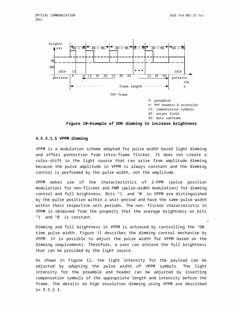
OPTICAL COMMUNICATION IEEE Std 802.15.7r1-20xx
Figure 24—Beacon frame
format 5.4.3.1 Beacon frame MHR fields
TBD
5.4.3.2 Superframe Spec field
The Superframe Spec field shall be formatted as illustrated in Figure 25.
Figure 25—Superframe Spec field
The Beacon Order subfield shall specify the transmission interval of the beacon. Refer to clause xx for an explanation of the relationship between the beacon order and beacon interval.
The VPAN Mode subfield specifies the topology mode of the VPAN, and shall be contain one of the nonre-served values listed in Table 9 1.
Insert Table 9 1 Valid values of the VPAN Mode subfield here from 16/360r0
The Beacon Type subfield shall be set to one if the beacon frame is a normal beacon which is transmitted in the beacon period regularly, and set to zero if the beacon frame is an additional beacon which is transmitted in a GTS in the CFP period.
The Association Permit subfield shall be set to one if macAssociationPermit is set to TRUE (i.e., the coordi-nator is accepting association to the VPAN). The association permit bit shall be set to zero if the coordinator is currently not accepting association requests on its network.
Copyright © 2011 IEEE. All rights reserved. 45

IEEE Std 802.15.7r1-20xx IEEE STANDARD FOR SHORT-RANGE WIRELESS
The CFP Presence Indication subfield shall be set to one if the superframe includes a CFP region, otherwise, the CFP Presence Indication subfield shall be set to zero. If this subfield is set to 1, the beacon frame shall include the corresponding CFP descriptor field.
The Countdown field indicates the number of superframes after which the previously announced new con-figuration parameters of the VPAN shall take effect. The value of this field shall decrement by one in each superframe until the Countdown is complete.
5.4.3.3 BP Descriptor field
The BP Descriptor field shall be formatted as illustrated in Figure 26.
Figure 26—BP descriptor field
The Beacon Slot Number subfield shall contain the number of the beacon slots in the BP.
The Beacon Slot Used subfield shall indicates which beacon slot is used by this VPAN.
5.4.3.4 CAP Descriptor field
Figure 27—CAP descriptor field
The Section Number subfield indicates the number of the sections that the CAP is divided into. The CAP Descriptor field shall include N Section Descriptor, and N is the value that the Section Number subfield rep-resents.
The Section[i] Descriptor shall be formatted as illustrated in Table 9 2.
Insert Table 9 2 Section descriptor here from 16/360r0
46 Copyright © 20xx IEEE. All rights reserved.
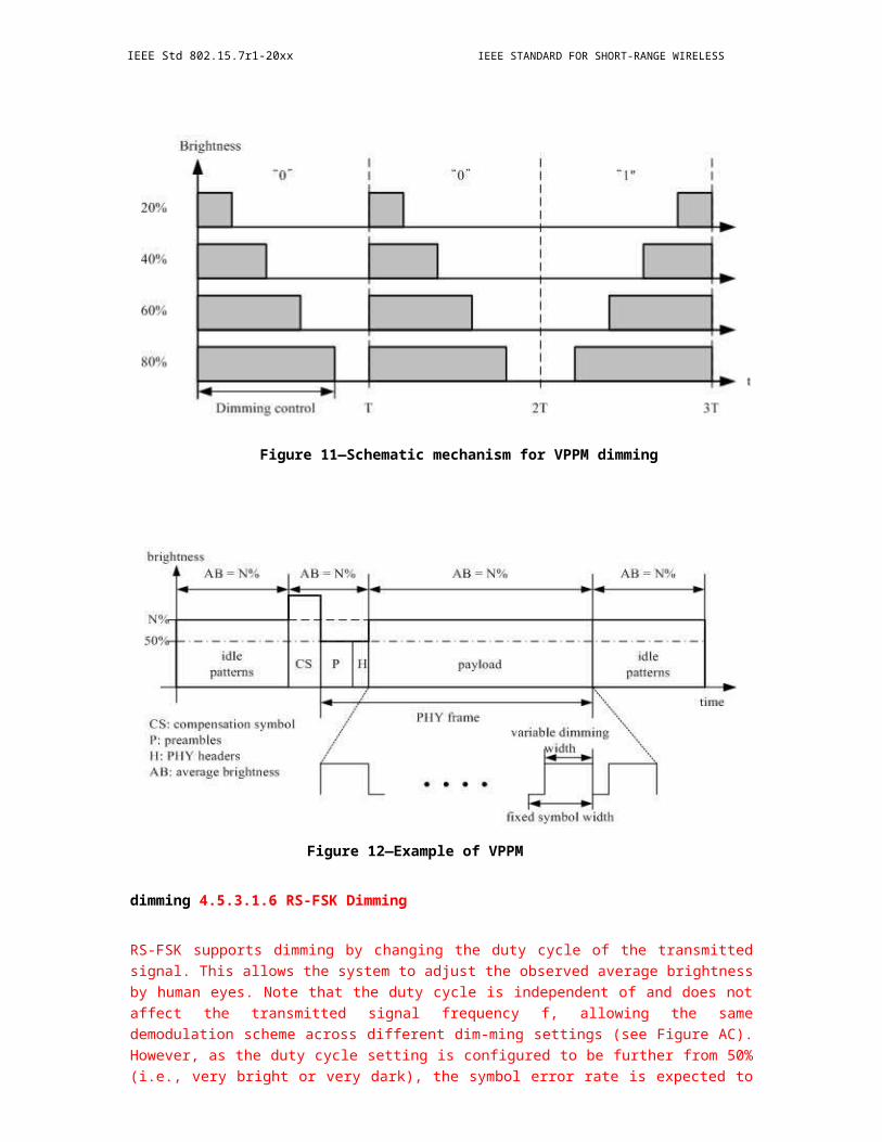
OPTICAL COMMUNICATION IEEE Std 802.15.7r1-20xx
Figure 28—CFP descriptor field
The GTS Number subfield indicates the number of the GTSs that the CFP is divided into. The CFP Descrip-tor field shall include N GTS Descriptor, and N is the value that the GTS Number subfield represents.
The GTS[i] Descriptor shall be formatted as illustrated in Table 9 3.
Insert Table 9 3 GTS descriptor here 16/360r0
The Beacon Payload field is an optional sequence of up to aMaxBeaconPayloadLength octets specified to be transmitted in the beacon frame by the next higher layer. The set of octets contained in macBeaconPayload shall be copied into this field.
5.4.4 Data frames
TBD
5.4.5 Acknowledgment frames
TBD
5.4.6 Command frames
5.4.6.1 Association request command
The association request command allows a device to request association with a VPAN through the coordina-tor. This command shall only be sent by an unassociated device that wishes to associate with a VPAN. A device shall only associate with a VPAN through the coordinator as determined through the scan procedure.
All devices shall be capable of transmitting this command, although a device is not required to be capable of receiving it.
The association request command shall be formatted as illustrated in Figure 29.
Copyright © 2011 IEEE. All rights reserved. 47

IEEE Std 802.15.7r1-20xx IEEE STANDARD FOR SHORT-RANGE WIRELESS
Figure 29—Association request command format
5.4.6.1.1 MHR fields
TBD
5.4.6.1.2 Capability Information field
TBD
5.4.6.1.3 Auxiliary parameters field
All allowed settings of Auxiliary parameters field are shown in Table 9 4. Only association request in star/ coordinated mode includes this auxiliary parameters field.
Insert Table 9 4 Auxiliary parameters field here 16/360r0
9.5.1.4 Interference Info field
A device may detect and collect the potential interference information when searching for the beacons before association. If the additional beacon frames of a VPAN have been detected, the device may include this field in the association request command to indicate the interference information of this VPAN.
The details are for further study.
5.4.6.2 Association response command
The association response command allows a coordinator to communicate the results of an association attempt back to the device requesting association. This command shall only be sent by a coordinator to a device that is currently trying to associate.
All devices shall be capable of receiving this command, although a device is not required to be capable of transmitting it.
The association response command shall be formatted as illustrated in Figure 30.
48 Copyright © 20xx IEEE. All rights reserved.
OPTICAL COMMUNICATION IEEE Std 802.15.7r1-20xx
Figure 30—Association request response format
5.4.6.2.1 MHR fields
TDB
5.4.6.2.2 Short Address Field
If the coordinator was not able to associate this device to its VPAN, the Short Address field shall be set to 0xffff, and the Association Status field shall contain the reason for the failure. If the coordinator was able to associate the device to its VPAN, this field shall contain the short address that the device may use in its com-munications on the VPAN until it is disassociated.
A Short Address field value equal to 0xfffe shall indicate that the device has been successfully associated with a VPAN, but has not been allocated a short address. In this case, the device shall communicate on the VPAN using only its 64-bit extended address.
5.4.6.2.3 Association Status field
The Association Status field shall contain one of the non-reserved values listed in Table 9 5.
Insert Table 9 5 Valid values of the Association Status field here from 16/360r0
5.4.6.2.4 Capability negotiation response field
TBD
5.4.6.3 Reassociation request
See section 7.2.3.6 of 802.11r
5.4.6.4 Reassociation response
See section 7.2.3.7 of 802.11r
9.5.5 Disassociation notification command
The VLC coordinator or an associated device may send the disassociate notification command. All devices shall implement this command.
The disassociation notification command shall be formatted as illustrated in Figure 31.
Copyright © 2011 IEEE. All rights reserved. 49
IEEE Std 802.15.7r1-20xx IEEE STANDARD FOR SHORT-RANGE WIRELESS
Figure 31—Disassociation notification command
5.4.6.4.1 MHR fields
TBD
5.4.6.4.2 Disassociation Reason field
The Disassociation Reason field shall contain one of the non-reserved values listed in Table 9 6.
Insert Table 9 6 Valid disassociation reason codes here
5.4.6.5 Disassociation response command
TBD
5.4.6.6 Beacon request command
The beacon request command is used by a device to locate all neighboring VPANs during an active scan.
The beacon request command shall be formatted as illustrated in Figure 9 10.
Octets: 1
MHR fieldsCommand Frame identifier
Figure 32—Beacon request command
50 Copyright © 20xx IEEE. All rights reserved.
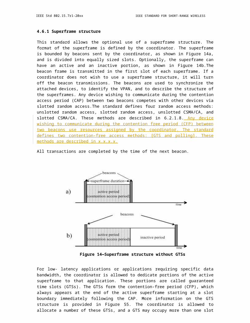
OPTICAL COMMUNICATION IEEE Std 802.15.7r1-20xx
5.4.6.7 Additional Beacon request command
The beacon request command is sent by a device to request a coordinator to send additional beacon frames.
The command is optional for a device.
The beacon request shall be formatted as illustrated in Figure 9 11.
Octets 1 1
MHR fieldsCommand Frame identifierReason
Figure 33—Additional beacon request command
5.4.6.7.1 MHR fields
TBD
5.4.6.7.2 Reason field
The Reason field shall contain one of the non-reserved values listed in Table 9 7.
Insert Table 9 7 Reason field here
5.4.6.8 Scan-over-backhaul request command
The scan-over-backhaul request command shall be send by a prospective coordinator to other coordinators through the backhaul link if inter-coordinator communication over backhaul is feasible.
The scan-over-backhaul request command shall be formatted as illustrated in Figure 9 12.
Octets: 1
MHR fieldsCommand Frame identifier
Copyright © 2011 IEEE. All rights reserved. 51

IEEE Std 802.15.7r1-20xx IEEE STANDARD FOR SHORT-RANGE WIRELESS
Figure 34—Scan-over-backhaul request command
5.4.6.9 Scan-over-backhaul confirmation command
The scan-over-backhaul confirmation command shall be sent by a coordinator as a response to a previous received scan-over-backhaul request command through the backhaul.
The scan-over-backhaul confirmation command shall be formatted as illustrated in Figure 35.
Figure 35—Scan-over-backhaul confirmation command
5.4.6.9.1 MHR fields
TBD
5.4.6.9.2 VPANDescriptorList
VPANDescriptorList contains the information of the VPAN whose coordinator generates the scan-over-backhaul confirmation command.
5.4.6.10 VPAN ID conflict notification command
The VPAN ID conflict notification command is sent by a device to the coordinator to report a VPAN ID con-flict detected by the device.
The VPAN ID conflict notification command shall be formatted as illustrated in Figure 36.
52 Copyright © 20xx IEEE. All rights reserved.
OPTICAL COMMUNICATION IEEE Std 802.15.7r1-20xx
Figure 36—VPAN ID conflict notification command
5.4.6.11 Neighboring VPAN report request command
The neighboring VPAN report request command is sent by the coordinator to devices to request a report of neighboring VPAN information detected by the devices.
The neighboring VPAN report request command shall be formatted as illustrated in Figure 9 15.
Octets 1
MHR fieldsCommand Frame identifier
Figure 37—Neighboring VPAN report request command
5.4.6.12 Neighboring VPAN report indication command
The neighboring VPAN report indication command is sent by the device to the coordinator to report neigh-boring VPAN information. The neighboring VPAN information is recorded in a local neighboring VPAN descriptor list, each record in the list corresponding to the information of one neighboring VPAN that can be detected by the device.
The neighboring VPAN report indication command shall be formatted as illustrated in Figure 9 16.
Octets: see 5.2.2.41
MHR fieldsCommand Frame identifierLocal neighboring VPAN descriptor list
Copyright © 2011 IEEE. All rights reserved. 53
IEEE Std 802.15.7r1-20xx IEEE STANDARD FOR SHORT-RANGE WIRELESS
Figure 38—Neighboring VPAN report indication
command 5.4.6.12.1 MHR fields
TBD
5.4.6.12.2 Local neighboring VPAN descriptor list
The local neighboring VPAN descriptor list field contains neighboring VPANs information that can be detected by the device. The detailed format is Table 8 1.
5.4.6.13 Flow Establishment Request command
The coordinator or an associated device can send this command to request establishing a flow. This com-mand can be used by an associated device that is requesting allocation of a GTS from the coordinator.
The Flow Establishment Request command shall be formatted as illustrated in Figure 39.
Figure 39—Flow establishment request
command 5.4.6.13.1 MHR fields
TBD
5.4.6.13.2 Control Indication field
All allowed settings of Control Indication field are shown in Table 9 8.
Insert Table 9 8 Control indication field here
54 Copyright © 20xx IEEE. All rights reserved.
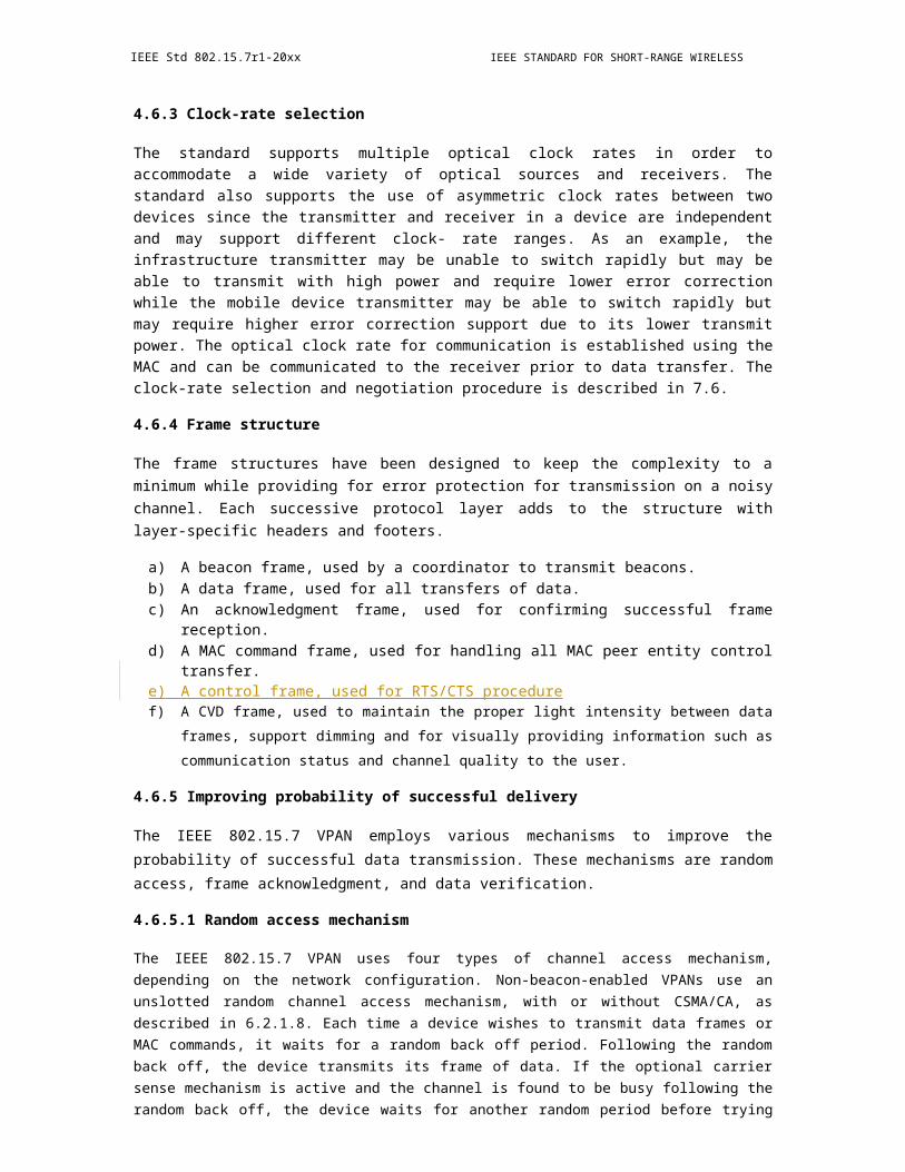
OPTICAL COMMUNICATION IEEE Std 802.15.7r1-20xx
5.4.6.13.3 FLOW ID_F field
FLOW ID_F field indicates the FLOW ID of the forwarding flow, i.e., from the originator to the recipient.
The coordinator shall assign a unique FLOW ID to a flow in the VPAN. If this command is sent by the coor-dinator (Bit1 of Control Indication field is set to 0), the FLOWID _F field shall be set to a non-zero value that has not been assigned to other flows. If this command is sent by a device, the FLOW ID_F field does not exist.
5.4.6.13.4 TSpec_F field
TBD
5.4.6.13.5 FLOW ID_R field
FLOW ID_F field indicates the FLOW ID of the reverse flow, i.e., from the recipient to the originator.
If this command is sent by the coordinator, the FLOWID _ R field shall be set to a non-zero value that has not been assigned to other flows. If this command is sent by a device, the FLOW ID_Rfield shall be set to 0x00.
5.4.6.13.6 TSpec_R field
TBD
5.4.6.14 Flow Establishment Response command
The Flow Establishment Response command is sent in response to a Flow Establishment Request command. When used, the Flow Establishment Response command shall be formatted as illustrated in Figure xx.
The Flow Establishment Request command shall be formatted as illustrated in Figure xx.
Octets: see 5.2.2.411 1 1 1 1
MHR fieldsCommand Frame identifierControl
IndicationFLOW ID_FStatus_FFLOW ID_RStatus_R
Figure 40—Flow establishment response command
5.4.6.14.1 MHR fields
TBD
Copyright © 2011 IEEE. All rights reserved. 55
IEEE Std 802.15.7r1-20xx IEEE STANDARD FOR SHORT-RANGE WIRELESS
5.4.6.14.2 Control Indication field
Same as 9.5.14.2.
5.4.6.14.3 FLOW ID_F field
The coordinator shall assign a unique FLOW ID to a flow in the VPAN. If Bit1 of Control Indication field is set to 0, the FLOW ID_F field does not exist. If Bit1 of Control Indication field is set to 1, the FLOWID _F field shall be set to a non-zero value that has not been assigned to other flows.
5.4.6.14.4 Status_F field
The Status_F field indicates the status of the request to establish a forwarding flow, and shall contain one of the non-reserved values listed in Table 9 9.
Insert Table 9 9 Status_F field here
5.4.6.14.5 FLOW ID_R field
The coordinator shall assign a unique FLOW ID to a flow in the VPAN. If Bit1 of Control Indication field is set to 0, the FLOW ID_R field does not exist. If Bit1 of Control Indication field is set to 1, the FLOWID _R field shall be set to a non-zero value that has not been assigned to other flows.
5.4.6.14.6 Status_R field
The Status_R field indicates the status of the request to establish a reverse flow, and shall contain one of the nonreserved values listed in Table 9 10.
Insert Table 9 10 Status_R field here
5.4.6.15 Flow Modify Request Command
The Flow Modify Request Command is sent by the coordinator to a device to alter the traffic contract.
The Flow Modify Request Command shall be formatted as illustrated in Figure 41.
Figure 41—Flow Modify Request Command
5.4.6.15.1 MHR fields
TBD
56 Copyright © 20xx IEEE. All rights reserved.
OPTICAL COMMUNICATION IEEE Std 802.15.7r1-20xx
5.4.6.15.2 FLOW ID field
This field shall be set to the FLOW ID of a flow, for which the coordinator wishes to alter the traffic con-tract.
5.4.6.15.3 Proposed TSpec field
TBD
5.4.6.16 Flow Modify Response Command
The Flow Modify Response Command is sent by the device to the coordinator in response to GTS Modify Request Command.
The Flow Modify Response Command shall be formatted as illustrated in Figure 9 20.
Octets: 1 1 1
MHR fieldsCommand Frame identifierFLOW IDStatus
Figure 42—Flow Modify Response Command
Figure 9 20 Flow Modify Response Command
5.4.6.16.1 MHR fields
TBD
5.4.6.16.2 FLOW ID field
This field shall be set to the FLOW ID of a flow, for which the coordinator wishes to alter the traffic con-tract.
5.4.6.16.3 Status field
The Status field indicates the status of the request to modify the traffic contract of a flow, and shall contain one of the non-reserved values listed in Table 9 11.
Insert Table 9 11 Status field here
Copyright © 2011 IEEE. All rights reserved. 57
IEEE Std 802.15.7r1-20xx IEEE STANDARD FOR SHORT-RANGE WIRELESS
5.4.6.17 Flow Terminate Request Command
The coordinator or an associated device can send this Flow Release Request Command to request terminat-ing a flow.
The Flow Release Request Command shall be formatted as illustrated in Figure 9 21.
Figure 43—Flow terminate request command
Figure 9 21 Flow terminate request command
5.4.6.17.1 MHR fields
TBD
5.4.6.17.2 FLOW ID field
This field shall be set to the FLOW ID of a flow, which the sender wishes to terminate.
5.4.6.17.3 Reason field
The Reason field indicates why the sender terminates the flow, and shall contain one of the non-reserved val-ues listed in Table 9 12.
Insert Table 9 12 Reason field here
5.4.6.18 Flow Terminate Response Command
This command is sent as a reply to a received Flow Release Response Command.
The Flow Release Response Command shall be formatted as illustrated in Figure 9 22.
Octets: 1 1 1
MHR fieldsCommand Frame identifierFLOW IDStatus
58 Copyright © 20xx IEEE. All rights reserved.
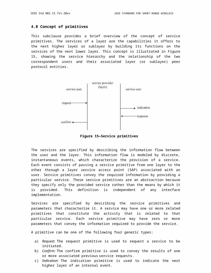
OPTICAL COMMUNICATION IEEE Std 802.15.7r1-20xx
Figure 44—Flow terminate response command
5.4.6.18.1 MHR fields
TBD
5.4.6.18.2 FLOW ID field
This field shall be set to the FLOW ID of the terminated flow.
5.4.6.18.3 Status field
The Status field indicates the status of the termination, and shall contain one of the non-reserved values listed in Table 9 13.
Insert Table 9 13 Status field here
5.4.6.19 Coordinator realignment command
See section 5.3.7 of 802.15.7-2011.
5.4.7 Control frames
5.4.7.1 RTS frame
TBD
5.4.7.2 CTS frame
TBD
Copyright © 2011 IEEE. All rights reserved. 59

IEEE Std 802.15.7r1-20xx IEEE STANDARD FOR SHORT-RANGE WIRELESS
6. MAC protocol specification
This clause specifies the MAC sublayer of this standard. The MAC sublayer handles all access to the physical layer and is responsible for the following tasks:
a) Generating network beacons if the device is a coordinatorb) Synchronizing to network beaconsc) Supporting VPAN association and disassociationd) Supporting color functione) Supporting visibilityf) Supporting dimmingg) Flicker-mitigation schemeh) Supporting visual indication of device status and channel qualityi) Supporting device securityj) Providing a reliable link between two peer MAC entitiesk) Supporting mobility
Peer-to-peer, star, and broadcasting and coordinated capabilities, as shown in Figure 1, are provided with a single MAC frame structure. All of these diverse modes are supported via a single low complexity integrated frame structure.
Constants and attributes that are specified and maintained by the MAC sublayer are written in the text of this clause in italics. Constants have a general prefix of “a”, e.g., aBaseSlotDuration, and are listed in Table 61 (see 7.5.1). Attributes have a general prefix of “mac”, e.g., macAckWaitDuration, and are listed in Table 62 (see 7.5.2), while the security attributes are listed in Table 69 (see 8.5.1).
6.1 PureLiFi MAC Superframe Structure (16/310r0)
6.1.1 Duplex Mode
6.1.2 5.2. Network Topologies
The current specification supports three basic network topologies as described in Fig. 5.2.1. The peer-to-peer topology constitutes two communication nodes exchanging information only between each other. This topology is equivalent to a single -user star topology. The star topology constitutes a networking configuration of an AP with multiple user STAs connected and served simultaneously. It is enabled by the subsequent protocol description. The broadcast topology constitutes a star topology in which transmission is unidirectional. Information is broadcasted only by the coordinator node. Reception acknowledgments are not expected in this configuration, but can be enabled in accordance with the multiple access mechanism described in the subsequent specification.
6.1.3 Superframe
The specification employs a superframe structure similar to the 802.15.7 superframe specification. The description provided in this subclause is illustrated in Fig. 5.3.1. The start of a transmission period is marked by the transmission of a beacon frame, which carriers the information required for new STAs to initiate an association procedure. Following the beacon frame transmission, a contention-based transmission period is enabled. The duration of the period is measured in terms of transmission slots, which the coordinator node enables via its polling mechanism. Each frame transmission (other than the Beacon frame transmission) by the coordinator can be used to poll a STA. During the contention-based period, all STAs are effectively polled by the coordinator and, as soon as they recognize the beginning of the polling frame (polling information is contained in the frame header at the beginning of the frame), they have the possibility to transmit. Collisions result in failed frame reception, which results in lack of acknowledgments and retransmission of the respective frames. Acknowledgments and retransmissions are described in subsection
60 Copyright © 20xx IEEE. All rights reserved.
OPTICAL COMMUNICATION IEEE Std 802.15.7r1-20xx
5.4.7. A STA which does not take the opportunity to transmit when polled during the CP needs to wait for the next valid frame transmitted by the coordinator, which marks the beginning of the next contention slot, in order to have the opportunity to transmit again. The polling mechanism enables very low-complexity synchronization of the transmission slots and also enables the coordinator to dynamically adapt and assign the slots for transmission. The duration of the CP is measured in terms of transmission slots and can be configured at the coordinator node. Following the CP, a CFP is enabled, during which the coordinator node polls each STA individually and allows it to transmit without any interference from other STAs. The specific polling algorithm and order is outside the scope of this specification and is left as a system designer's choice. STA association and disassociation begins in the CP, but can be completed during the subsequent CFP.
Figure 45—Network topologies: (a) peer-to-peer; (b) star; (c) broadcast
6.1.4 VPAN Establishment
6.1.4.1 Association and Disassociation
A Beacon frame is broadcasted from the AP to the STAs, after which a contention period is enabled for new stations to request to join the AP via a poll request. Poll acknowledgments are
Figure 46—Superframe structure example with four STAs
also used by already connected STAs for Beacon acknowledgment, which indicates to the AP that the respective STA is still within range and able to communicate.
6.1.4.1.1 Association
The AP sends a Beacon frame periodically at the beginning of a polling cycle. In a short contention period after receiving the Beacon frame, the STA can reply with a "connection request", which is a poll request frame (a Data Null frame) transmitted by the STA. The first valid downlink frame after the beacon marks the beginning and the end of the contention period, i.e., the first valid frame after the beacon is interpreted as a
Copyright © 2011 IEEE. All rights reserved. 61
IEEE Std 802.15.7r1-20xx IEEE STANDARD FOR SHORT-RANGE WIRELESS
poll to all stations that have not been connected to transmit their poll request in the form of a Data Null frame. All stations that have already been associated with the AP may ignore any polling during the contention period. If no stations have been connected to the AP, the first valid frame would be the subsequent beacon frame (see Fig. 5.4.2.1. for a description of this procedure). The AP starts polling a station in the next polling round after receiving the Data Null frame (polling request). In case several STAs want to connect at the same time, a collision occurs. As a solution, a random backoff is introduced, for example, one STA retries to establish a connection after 2 beacons, another STA retries after 5 beacons, etc. If it is not polled during the next polling round, a STA assumes a collision has occurred and proceeds accordingly with a back-off and an attempt to reconnect. A STA transmits a poll request frame immediately after it decodes a valid MAC frame header. Hence, as depicted in Fig. 7, it will not wait for the entire frame on the downlink from the AP to be transmitted. Upon a successful polling request (the AP has successfully received the station's request to be polled and has indicated this by polling the station within the next transmission
Figure 47—A STA sending a connection request to the AP
round), a station exchanges the necessary association and authentication information with the AP via association and authentication control frames. Upon successful authentication and association, the STA is assigned a unique 8-bit address which will identify the STA among all other devices connected to the same AP via the VLC link.
6.1.4.1.2 Disassociation
Stations are expected to acknowledge every Beacon frame with the transmission of a Data or Management frame using the designated bit in the MAC frame header as described in subclause 5.8. In case a Beacon is not acknowledged within the time interval between the transmission of the Beacon to be acknowledged and the transmission of the subsequent Beacon frame, the STA is assumed to have been disconnected and is removed from the polling algorithm at the AP. If a station does not receive a poll (any valid downlink frame with its address number in the field for the polled station address as described in 5.8) within a polling period, it assumes to have been disconnected and begins attempting to reconnect again after detecting a Beacon frame.
6.1.4.2 Link Maintenance
Once a link is established it is maintained using any available CSI and the respective control / management mechanisms defined in the current MAC specification.
6.1.4.3 CSI Feedback and Link Adaptation
The CSI can be obtained using the respective service primitives at the PHY layer and control / management mechanisms defined in the current MAC layer specification.
62 Copyright © 20xx IEEE. All rights reserved.
OPTICAL COMMUNICATION IEEE Std 802.15.7r1-20xx
6.1.4.3.1 Setup and Link Adaptation for MIMO Communication
To setup the MIMO communication, it is assumed that the association is realized in SISO mode. At any point in time after a VLC communication node has been successfully associated to a network (for APs, this occurs after an AP has associated a given mobile STA), the VLC communication node sends a MIMO information request in order to start a MIMO setup procedure using a MIMO control frame. The node that receives the request provides the number of MIMO channels it can support and its relevant MIMO capability parameters using a MIMO control frame. The initiating node acknowledges the reception of the MIMO information parameters and transmits a packet in MIMO mode in order to perform the channel estimation process. The packet is a Data Null packet, which the transmitting node does not expect to be acknowledged. However, the transmitting node does expect MIMO control frame in return containing the estimated communication channel parameters. Similarly, the second node also transmits a Data Null frame in MIMO mode, so that the initiating node can estimated the MIMO communication channel conditions in the other direction. Upon estimation of the channel state information (CSI), each node transmits a MIMO control frame containing the bit loading for every OFDM subcarrier on each communication channel. The channel state information (i.e., channel coefficients, channel correlation, signal-to-noise ratio etc.) is estimated by the receiving node in each direction. Based on the channel conditions, the receiver selects the optimal transmission mode, which includes modulation type, modulation order, MIMO configuration and MIMO type. The selected transmission mode is provided to the transmitter via MIMO control frames. The concept is illustrated in Fig. 5.4.4.1.1.
6.1.4.4 Interference Coordination
The CSI obtained using the respective service primitives at the PHY layer and control / management mechanisms at the MAC layer can be optionally used for interference coordination within the network. The coordinated optical wireless (COW) network concept is described in 5.7.
6.1.4.5 Multiple Access
The multiple access in the presented MAC protocol is based on the function of a PCF which provides CF frame transfer. The PC shall reside in the AP. It is also a requirement for a STA to be able to respond to a poll request received from a PC. A STA should also be able to request to be polled by an active PC as described in subclause 5.4.2. When polled by the PC, a STA may transmit only one MPDU, which can be sent to the PC but may have any destination. The acknowledgments for any data packet "piggyback" on the transmission of any management or data frame (including Null frames) except for Beacon frames. If a frame is not acknowledged, the STA shall not retransmit the frame unless it is polled again by the PC. If a polled STA does not have any data to transmit, it simply ignores the polling request. The request times out after a specified period of time, which indicates to the PC that the polled station might either be out of range or will not take advantage of the possibility to transmit.
Copyright © 2011 IEEE. All rights reserved. 63

IEEE Std 802.15.7r1-20xx IEEE STANDARD FOR SHORT-RANGE WIRELESS
Figure 48—MIMO communication setup
Any frames transmitted from the AP to the STA are treated as polling frames, except for the Beacon frame. This can be assumed because every packet transmission contains a polled STA number, which enables the stations to keep track of the polling order. A newly connected STA is made aware of its queue number with the first valid packet it receives from the AP, which contains both its queue number and its MAC address. Furthermore, the AP will never transmit a frame before the uplink from a STA due to a previous poll has been completed. Hence, no collisions in the uplink are possible and each donwlink packet transmission can function as a polling frame. In case the response to a poll request is not detected by the AP, the AP will attempt to poll the next STA in the queue. Upon detection of a subsequent downlink packet by the STA whose response was not detected, the STA will stop transmission immediately in order to avoid any collisions in the uplink as illustrated in Fig. 5.4.6.1. This functionality is necessary because the AP does not expect to always receive a response to its poll. If a STA has no acknowledgment or information to transmit, it will simply ignore its possibility to transmit. An AP always sends polling frames in order. In case there is no information to be transmitted to a STA, which is next in the queue, a Data Null frame is used as a polling frame.
Figure 49—Consequences of the AP failing to recognize a poll response
5.4.7. Acknowledgement and Retransmission
The reception of every packet at the MAC layer level has to be acknowledged by the receiving side (AP or STA). If a packet is not acknowledged by the STA or the AP at the following polling round, then it is retransmitted during the subsequent polling cycle. Packets may arrive out of order. Hence, even if a STA or an AP does not receive the expected acknowledgment during a given polling round, it can proceed with the transmission of the next packet. If packets are not acknowledged in the course of a predetermined time period equal to four transmission opportunities for the acknowledging device, they are considered lost and are dropped from the transmission. Figure 5.4.7.1 illustrates the acknowledgment procedure.
64 Copyright © 20xx IEEE. All rights reserved.
OPTICAL COMMUNICATION IEEE Std 802.15.7r1-20xx
The principle of operation is illustrated in Fig. 5.4.7.1 for transmission on the downlink. The principle of operation is analogous for the uplink direction. Two STAs are already connected to the AP. The AP sends a data frame to the first STA, which also polls the STA. The STA responds to the poll with a payload frame or a management frame as soon as it manages to decode the MAC header of the received frame. Note that if the high-reliability MAC header encoding at the PHY layer is implemented, then the STA responds as soon as this information is decoded at the PHY layer and the MLME is notified even before the entire DATA portion of the PHY packet is received and decoded. After both the downlink and the uplink packet transmissions are complete, the AP sends a data frame to the second STA, which also replies to the poll with a payload frame as soon as the PHY header is decoded. After completion of the transmission in both directions, the AP attempts to send a second data frame to the first STA. This time a CRC error is detected at the PHY layer, but the packet transmission is correctly detected by the STA, which interprets this as an invitation to transmit and responds with an acknowledgment to the first data packet in the downlink (note that if the high-reliability MAC header encoding at the PHY layer is not used, the entire packet would be dropped without the STA being polled, so uplink transmission would not be possible). The acknowledgment in this case is part of a Null frame, but can also be transmitted with a data frame if the STA had any data to upload. After transmission is complete in both directions, the AP sends a second data packet to the second STA. The STA detects this and after decoding the header, transmits an acknowledgment for the reception of the first data packet. Upon completion of both transmissions, the AP sends a third data packet to the first STA. The STA responds with a management frame, but does not provide any acknowledgments as the second data packet was not successfully received during the previous transmission cycle. In this case, the STA could simply ignore the possibility to transmit if no management information or data is available for transmission. In both cases, the AP would recognize the lack of an acknowledgment for the second data packet which failed to successfully reach the first STA. Upon completion of transmission in both directions, the AP sends a third data packet to the second STA. This time an error at the PHY layer causes the packet to not get detected at the PHY layer. As a result, the STA does not recognize the poll and does not transmit any data. After completing transmission, the AP transmits another data frame to the first STA. In this case, the second packet is retransmitted since no acknowledgment was received at the AP during the previous transmission cycle. At this point, the AP will keep transmitting the second data packet at each polling cycle, until an acknowledgment is received from the STA or until enough unsuccessful attempts are made so that the AP decides to drop the packet. The STA correctly identifies the packet header and transmits a response with an acknowledgment for the third data packet, which was received during the previous transmission round. Upon completion of both transmissions, the AP sends the fourth data packet to the second STA. The STA recognizes the header and sends a response in a management frame. In this case, again, the STA could simply ignore the possibility to transmit if no management information or data is available for transmission. In both cases, the AP would recognize the lack of an acknowledgment for the third data packet which failed to successfully reach the second STA. Upon completion of the bidirectional transmission, the AP transmits the fourth data packet to the first STA. The STA recognizes the header and transmits an acknowledgment for the second data packet, which was successfully retransmitted during the previous round. After completion of the bidirectional transmission, the AP retransmits the third data packet to the second STA for which it did not receive an acknowledgment in the previous round. The STA recognizes the header and attempts to transmit an acknowledgment for the fourth data packet which was successfully received during the previous round. The transmission, however, contains at least one error, which causes the PHY layer algorithm at the AP to drop the data, and, hence, the MAC layer algorithm does not receive the acknowledgment for the fourth data packet. Upon completion of both data transmissions, the AP continues with transmission of the fifth data packet to the first STA. It should be noted that if for any reason the AP failed to recognize the end of the uplink transmission from the second STA, which could be due to the fact that the packet was not detected at all or due to the fact that because of a PHY layer error the packet length was not correctly interpreted, and began transmitting the next packet to the first STA prematurely, the second STA would have discontinued its transmission immediately upon detecting the next donwlink packet transmission. This example was explained in subclause 5.4.6 and illustrated in Fig. 5.4.6.1. All subsequent packet transmissions in Fig. 5.4.7.1 are successful and analogous to the already explained examples. It is interesting to note that since the acknowledgment for the fourth data packet to the second STA was unsuccessful, the AP transmits this packet a second time (in the last illustrated frame), so the STA receives the packet successfully twice. The MAC layer protocol is able to handle the packet redundancy as well as reordering
Copyright © 2011 IEEE. All rights reserved. 65
IEEE Std 802.15.7r1-20xx IEEE STANDARD FOR SHORT-RANGE WIRELESS
based on the packet sequence numbers described in subclause 5.8 - the MAC Frame Description part of the document.
Figure 50—Downlink transmission with two STAs
6.1.5 Relaying
6.1.5.1 Relay Discovery Procedure
The MAC protocol supports optional relaying mechanism for the cases when dedicated relay terminals are available. The relay terminals are named as "relay STAs". The AP keeps track of the relay STAs in the environment. At any given point in time, the AP can send an Advanced Modulation Control frame to a STA, which contains the APs capabilities, but alos serves as a signal to the STA to transmit its own capabilities using an Advanced Modulation Control frame. All the STAs in the environment, that have received an Advanced Modulation Control frame including the relay STAs, reply with their capabilities. The AP collects the relaying capabilities of the STAs along with the full set of capabilities included in the Advanced Modulation Control frame. Subclause 5.8.4.3.1.5 describes the signalling mechanism for the relaying capabilities using the Advanced Modulation control frame. Note that this procedure can occur at different points in time for the different STAs.
Figure 51—Protocol for establishing STA relay capabilities
The PHY layer protocol at each STA measures the signal to interference and noise (SINR) on each subcarrier for each link and signals it to the AP through a CSI control frame. The AP obtains CQI reports, which can also be used for the additional advanced modulation capabilities. Subclause 5.8.4.3.2 describes the structure of the CSI control frame. Note that this procedure can occur at different points in time for the different STAs and also is not obligatory before every relaying instruction, given that the CSI available to the AP is still applicable. The relay discovery procedure is illustrated in Fig. 5.5.1.1.
66 Copyright © 20xx IEEE. All rights reserved.

OPTICAL COMMUNICATION IEEE Std 802.15.7r1-20xx
Figure 52—Relay selection procedure
6.1.5.2 Relay Selection Procedure
The relay selection procedure defines selection of the best relay STA and relaying mode among multiple relay STAs. The relay selection procedure is based on the capabilities for each relay STA and the CSI available at the AP. Figure 5.5.2.1 shows the best relay selection algorithm based on the predefined constraints and performance metrics. The AP calculates the constraint metric for each relay with HD/FD and AF/DF relaying modes. Then, the transmitter decides the best relay together with a relaying mode that satisfies the constraint.
6.1.5.3 Relay Link Setup (RLS) Procedure
Following the selection of the relay to be used between the AP and STA, a RLS request frame is sent to the selected relay. The RLS Request frame includes the capabilities and the IDs of the AP, the STA and the relay transfer parameter set. Upon receiving the RLS Request frame, the relay STA shall transmit a RLS Request frame to the destination containing the same information as received within the frame body of the source RLS Request frame. RLS response frame indicates whether the STA can participate in the RLS. Finally, the AP transmits the RLS announcement that indicates the RLS procedure was successfully completed.
6.1.5.4 Frame Exchange Rules
Figure 5.5.4.1 pictures the packet loss and retransmission scenarios for HD relaying. In Fig. 5.5.4.1, there is a single user in the network. The AP transmits the first data packet to the STA. The packet is received by both the STA and the relay STA. The STA responds as soon as it decodes the header. The response is received by both the AP and the relay STA. The AP is aware of the relay STA and waits for its response. The response from the relay STA is also received by the AP. The relay STA stores the first data packet until it receives its acknowledgement.
Then in the second transmission cycle, the AP sends the second data packet which is received by both the STA and the relay STA. The relay STA starts to store the second data packet. First, the STA responds with the ACK for the first packet. Then, the relay STA sends its response with the ACK of the first packet and deletes the first package from its memory. In the next transmission cycle, the AP transmits the third data packet which is this time received by the relay STA only. The STA does not respond to this packet. The relay STA waits for the response from the STA over a predetermined amount of time and then sends its response to the AP. The response from the relay STA includes the information that it did not receive a response from the STA and will retransmit the third packet to the STA. The AP starts to wait for the next response from the relay STA. The relay STA retransmits the third packet. The STA responds with the ACK for the second data packet. The relay STA also sends its response with ACK from STA. Then, the relay STA deletes the second data packet.
Copyright © 2011 IEEE. All rights reserved. 67
IEEE Std 802.15.7r1-20xx IEEE STANDARD FOR SHORT-RANGE WIRELESS
6.1.5.5 RLS Teardown Procedure
The RLS Teardown procedure is to terminate the relay operation. The RLS teardown frame is sent by the AP and received by the relay STA. Then, the relay STA terminates the relaying operation for any subsequent packets.
Figure 53—RLS procedure
Figure 54—Packet loss and retransmission scenario in HD
relaying 6.1.6 Mobility and Handover
Mobility and handover techniques is envisioned to be adopted from the protocols described in the IEEE 802.11k and IEEE 802.11r specifications.
6.1.7 Coordinated Wireless Network
In the COW topology, multiple STAs are served by multiple APs, which are in turn coordinated by a network controller (NC). The NC is a device that has a fixed network link to the APs. The NC reroutes the traffic paths between NC and APs in case of handover and controls the transmission of all APs and STAs to manage interference. APs are time-synchronized, what can be achieved e.g. by the IEEE 1588 precision time protocol (PTP). The NC aggregates the wireless traffic of STAs and APs. However, its functionality is not part of 802.15.7r1. Only the specific data transport and control signaling needed in the COW topology are defined. Based on cell-specific reference signals, STAs and APs estimate the interference channel in down-and uplink directions, respectively. The corresponding metrics reports are conveyed in the downlink over the wireless uplink and via the APs to the NC and ii) in the uplink via the APs to the NC where it is used for interference coordination and handover.
68 Copyright © 20xx IEEE. All rights reserved.
OPTICAL COMMUNICATION IEEE Std 802.15.7r1-20xx
6.1.8 Heterogeneous VLC and RF communication
Optional techniques for combined VLC and RF communication will be introduced, where a STA is simultaneously connected to an AP using RF communication as well as VLC. MAC layer service primitives enable control information and data to be conveyed between the MAC layer and the upper network layers so the control information and the data can be conveyed to the destination using either one of the two wireless communication media.
6.1.9 Encryption and Security
The MAC layer protocol is expected to provide encryption and security features using the following set of protocols:
1) Wired Equivalent Privacy (WEP)
2) Temporal Key Integrity Protocol (TKIP)
3) Counter Mode Cipher Block Chaining Message Authentication Code Protocol
(CCMP)
6.1.10 MAC Layer Service Primitives
The MAC layer service primitives enable the transfer of data and control information between the MAC layer and the higher networking layers. The following service primitives are defined.
6.1.10.1 MAC Layer DATA Services
6.1.10.1.1 MAC-DATA.request
5.11.1.1.1 Function
This primitive requests a transfer of an MSDU from a local LLC sublayer entity to a single peer LLC sublayer entity, or multiple peer LLC sublayer entities in the case of group addresses or broadcasting.
5.11.1.1.2 Semantics of the service primitive
MAC-DATA.request (source address,
destination address,
data)
The source address (SA) parameter specifies an individual MAC sublayer address of the sublayer entity from which the MSDU is being transferred.
The destination address (DA) parameter specifies either an individual or a group MAC sublayer entity address.
The data parameter specifies the MSDU to be transmitted by the MAC sublayer entity. The length of the MSDU must be less than or equal to 2304 octets.
5.11.1.1.3 When Generated
Copyright © 2011 IEEE. All rights reserved. 69
IEEE Std 802.15.7r1-20xx IEEE STANDARD FOR SHORT-RANGE WIRELESS
This primitive is generated by the LLC sublayer entity when an MSDU is to be transferred to a peer LLC sublayer entity or entities.
5.11.1.1.4 Effect of Receipt
On receipt of this primitive, the MAC sublayer entity determines whether the request can be fulfilled. A request that cannot be fulfilled is discarded, and this action is indicated to the LLC sublayer entity using an MAC-DATA.confirm primitive that describes why the MAC was unable to fulfill the request. If the request can be fulfilled, the MAC sublayer entity appends all MAC specified fields, passes the properly formatted frame to the lower layers for transfer to a peer MAC sublayer entity or entities, and indicates this action to the LLC sublayer entity using an MAC-DATA.confirm primitive with transmission status set to Successful.
6.1.10.1.2 MAC-DATA.indication
5.11.1.2.1 Function
This primitive defines the transfer of an MSDU from the MAC sublayer entity to the LLC sublayer entity, or entities in the case of broadcast transmission. In the absence of error, the contents of the data parameter are logically complete and unchanged relative to the data parameter in the associated MAC-DATA.request primitive.
5.11.1.2.2 Semantics of the service primitive
MAC-DATA.indication (source address,
destination address,
reception status,
data)
The source address (SA) parameter specifies an individual MAC sublayer address of the sublayer entity from which the MSDU is being transferred.
The destination address (DA) parameter specifies either an individual or a group MAC sublayer entity address.
The data parameter specifies the MSDU as received by the local MAC entity.
The reception status parameter indicates "success" or "failure" of the received frame for those frames that the MAC layer reports using the MAC-DATA.indication primitive.
5.11.1.2.3 When Generated
The MAC-DATA.indication primitive is passed from the MAC sublayer entity to the LLC sublayer entity or entities to indicate the arrival of a frame at the local MAC sublayer entity. Frames are reported only if they are validly formatted at the MAC sublayer, received without error, received with valid (or null) security and integrity information, and their destination address designates the local MAC sublayer entity.
5.11.1.2.4 Effect of Receipt
The effect of receipt of this primitive by the LLC sublayer is dependent on the content of the MSDU.
70 Copyright © 20xx IEEE. All rights reserved.
OPTICAL COMMUNICATION IEEE Std 802.15.7r1-20xx
6.1.10.1.3 MAC-DATA.confirm
5.11.1.3.1 Function
This primitive has local significance and provides the LLC sublayer with status information for the corresponding preceding MA-UNITDATA.request primitive.
5.11.1.3.2 Semantics of the service primitive
MAC-DATA.indication (source address,
destination address,
transmission status)
The SA parameter is an individual MAC sublayer entity address as specified in the associated MAC-DATA.request primitive.
The DA parameter is either an individual or group MAC sublayer entity address as specified in the associated MAC-DATA.request primitive.
The transmission status parameter is used to pass status information back to the local requesting LLC sublayer entity. IEEE Std 802.11 specifies the following values for transmission status:
a) Successful.
b) Undeliverable (excessive data length).
c) Undeliverable (no BSS available).
d) Undeliverable (cannot encrypt with a null key).
5.11.1.3.3 When Generated
The MAC-DATA.confirm primitive is passed from the MAC sublayer entity to the LLC sublayer entity to indicate the status of the service provided for the corresponding MAC-DATA.request primitive.
5.11.1.3.4 Effect of Receipt
The effect of receipt of this primitive by the LLC sublayer is dependent upon the type of operation employed by the LLC sublayer entity.?
6.2 MAC functional description
This subclause provides a detailed description of the MAC functionality. Subclause 6.2.1 describes the following two mechanisms for channel access: contention based and contention free. Contention-based access allows devices to access the channel in a distributed fashion using an unslotted random access backoff algorithm. Contention-free access is controlled entirely by the coordinator through the use of GTSs.
The mechanisms used for starting and maintaining a VPAN are respectively described in 6.2.2 and 6.2.3. Channel scanning is used by a device to assess the current state of a channel (or channels), locate all beacons
Copyright © 2011 IEEE. All rights reserved. 71

IEEE Std 802.15.7r1-20xx IEEE STANDARD FOR SHORT-RANGE WIRELESS
within its operating space, or locate a particular beacon with which it has lost synchronization. Before starting a new VPAN, the results of a channel scan can be used to select an appropriate logical channel, as well as a VPAN identifier that is not being used by any other VPAN in the area. Because it is still possible for the operating space of two VPANs with the same VPAN identifier to overlap, a procedure exists to detect and resolve this situation. Following a channel scan and suitable VPAN identifier selection, operation as a coordinator shall commence. Also described in the subclause is a method to allow coordinator beaconing to discover other such devices during normal operations, i.e., when not scanning.
The mechanisms to allow devices to join or leave a VPAN are defined in 6.2.4. The association procedure describes the conditions under which a device may join a VPAN and the conditions necessary for a coordinator to permit devices to join. Also described is the disassociation procedure, which can be initiated by the associated device or its coordinator.
The mechanisms to allow devices to acquire and maintain synchronization with a coordinator are described in 6.2.5. Synchronization on a beacon-enabled VPAN is described after first explaining how a coordinator generates beacon frames. Following this explanation, synchronization on a nonbeacon-enabled VPAN is described. Also described is a procedure to reestablish communication between a device and its coordinator, as it is possible that a device may lose synchronization in the case of either a beacon-enabled or a nonbeacon-enabled VPAN.
This standard has been designed so that application data transfers can be controlled by the devices on a VPAN rather than by the coordinator. The procedures the coordinator uses to handle multiple transactions while preserving this requirement are described in 6.2.6.
The mechanisms for transmitting, receiving, and acknowledging frames, including frames sent using indirect transmission, are described in 6.2.7. In addition, methods for retransmitting frames are also described.
The mechanisms for allocating and deallocating a GTS are described in 6.2.8. The deallocation process may result in the fragmentation of the GTS space, i.e., an unused slot or slots. The subclause describes a mechanism to resolve fragmentation.
The MAC sublayer uses the mechanisms described in Clause 8 for all incoming and outgoing frames.
Throughout this subclause, the receipt of a frame is defined as the successful receipt of the frame by the PHY and the successful verification of the FCS by the MAC sublayer, as described in 6.4.1.9.
The mechanisms to allow devices to recover quickly in case of temporary interference using a fast link recovery process are defined in 6.2.9. The fast link recovery process also enables devices to save power by letting the infrastructure initiate the link recovery.
The mechanisms to allow devices to use multiple channels in case of limited time resources or interference are defined in 6.2.10. Multiple channel resource assignment uses information about multiple channel support and band hopping in order to support more users or improve performance.
The mechanisms to support mobility of the device under an infrastructure that supports multiple optical elements over a wide coverage area are defined in 6.2.11. The concept of a cell is introduced and the support for mobility across multiple cells supported by the infrastructure is presented.
The mechanisms to visually indicate to the user the various states using various colors are defined in 6.2.12. The various states such as device discovery (scan, association, disassociation), file transfer status, wavelength quality indication and acknowledgments can be visually indicated to the user to help with device alignment for communication.
72 Copyright © 20xx IEEE. All rights reserved.
OPTICAL COMMUNICATION IEEE Std 802.15.7r1-20xx
The mechanisms to stabilize the optical color emitted by the transmitter are defined in 6.2.13. The CVD frames are used to estimate the change in color and this information can be provided as feedback to the transmitter to stabilize its color.
The mechanisms for using the visibility and dimming information in the MAC are defined in 6.2.14. Features such as an extended preamble mode for providing visibility with improved synchronization performance, dimming overrides, adjusting the MAC layer transmission schedule to accommodate dimming, association and link adaptation in the presence of dimming are provided.
6.2.1 Channel access
This subclause describes the mechanisms for accessing the physical optical channel. The standard provides a single VLC MAC frame structure that can be configured for multiple modes. The frame is composed of a variable number of slots. A slot can be defined as the minimum time needed to communicate to send the smallest data to a device and is fixed.
6.2.1.1 Superframe structure
A coordinator on a VPAN can optionally bound its channel time using a superframe structure. A superframe is bounded by the transmission of a beacon frame and can have an active portion and an inactive portion. The coordinator may enter a low-power (sleep) mode during the inactive portion.
The structure of this superframe is described by the values of macBeaconOrder and macSuperframeOrder. The MAC PIB attribute macBeaconOrder, describes the interval at which the coordinator shall transmit its beacon frames. The value of macBeaconOrder, BO, and the beacon interval, BI, are related as follows: for
0 BO 14, BI = aBaseSuperframeDuration 2BO optical clocks. If BO = 15, the coordinator shall not transmit beacon frames except when requested to do so, such as on receipt of a beacon request command. The value of macSuperframeOrder shall be ignored if BO = 15.
The MAC PIB attribute macSuperframeOrder describes the length of the active portion of the superframe, which includes the beacon frame. The value of macSuperframeOrder, SO, and the superframe duration, SD,
are related as follows: for 0 SO BO, SD = aBaseSuperframeDuration 2SO optical clocks. If SO = 15, the superframe shall not remain active after the beacon. If BO = 15, the superframe shall not exist (the value of macSuperframeOrder shall be ignored), and macRxOnWhenIdle shall define whether the receiver is enabled during periods of transceiver inactivity.
The active portion of each superframe shall be divided into aNumSuperframeSlots equally spaced slots of
duration 2SO aBaseSlotDuration and is composed of three parts: a beacon or a beacon period (BP), a CAP and a CFP. BP exists in coordinated topology when comb division is not used, in PHY 7. [editor’s note: beacon interference avoidance using comb division for PHY 7 coordinated topology is described in D0 17.1.2.6.1]. The beacon shall be transmitted, without the use of any random access, at the start of slot 0, if BP doesn’t exist. If BP exists, beacon is transmitted without the use of any random access, in one beacon slot of BP. and tThe CAP shall commence immediately following the beacon. The start of slot 0 is defined as the point at which the first bit of the beacon PPDU is transmitted. The CFP, if present, follows immediately after the CAP and extends to the end of the active portion of the superframe. Any allocated GTSs shall be located within the CFP.
The MAC sublayer shall ensure that the integrity of the superframe timing is maintained, e.g., compensating for clock drift error.
VPANs that wish to use the superframe structure (referred to as a beacon-enabled VPAN) shall set macBeaconOrder to a value between 0 and 14, both inclusive, and macSuperframeOrder to a value between 0 and the value of macBeaconOrder, both inclusive.
VPANs that do not wish to use the superframe structure (referred to as a nonbeacon-enabled VPAN) shall set both macBeaconOrder and macSuperframeOrder to 15. In this case, a coordinator shall not transmit beacons, except upon receipt of a beacon request command; all transmissions, with the exception of acknowledgment frames and any data frame that quickly follows the acknowledgment of a data requestCopyright © 2011 IEEE. All rights reserved. 73
IEEE Std 802.15.7r1-20xx IEEE STANDARD FOR SHORT-RANGE WIRELESS
command, see 6.2.7.3, shall use an unslotted random access mechanism to access the channel. In addition, GTSs shall not be permitted.
An example of a superframe structure is shown in Figure 55. In this case, the beacon interval, BI, is twice as long as the active superframe duration, SD, and the CFP contains two GTSs.
Figure 55—An example of the superframe structure
peer-to-peer mode ( a ) all slots in frame used for same data
star
(b) beacon, contention, uplink, downlink slots
broadcast
(c) broadcast slots (beacon, downlink)
visibility mode
( d ) visibility slots
legend for slot indication
data beacon contention uplink downlink visibility
Figure 56—Example usage of frame structure for multiple topologies
Figure 56 provides an example usage of frame structure configuration for multiple topologies such as peer-to-peer, star, broadcast and visibility modes. The beacon slots are used for the beacons and the contention slots are used in the CAP period. The uplink and downlink GTS slots are used in the CFP periods. Visibility
74 Copyright © 20xx IEEE. All rights reserved.
OPTICAL COMMUNICATION IEEE Std 802.15.7r1-20xx
or idle patterns can be sent in the visibility slots during idle or RX modes of the infrastructure to ensure continuous output and mitigate flicker and are also used for point-and-shoot mode to ensure visibility.
6.2.1.1.1 Beacon period (BP)
BP exists in coordinated topology when comb division is not used, in PHY 7. [editor’s note: beacon interference avoidance using comb division for PHY 7 coordinated topology is described in D0 17.1.2.6.1]. The BP shall start at slot 0 of a superframe and complete before the beginning of the CAP on a superframe slot boundary. BP is further divided into multiple beacon slots as shown in Error: Referencesource not foundxx. The duration of each beacon slot is equal to the sum of the duration of a beacon physical layer data unit (PPDU) and the subsequent beacon-to-beacon inter-frame space. In peer-to-peer mode and star mode, the BP shall contain only one beacon slot. In coordinated network, the BP consists one to a maximal of MaxBeaconSlot beacon slots as shown in Figure xx. The structure of a BP is notified in the beacon frame (see xx).
Figure xx – Superframe structure of different topologies
Figure xx –Structure of beacon period
6.2.1.1.1 Contention access period (CAP)
The CAP shall start immediately following the beacon and complete before the beginning of the CFP on a superframe slot boundary. If the CFP is zero length, the CAP shall complete at the end of the active portion of the superframe. The CAP shall be at least aMinCAPLength optical clocks, unless additional space is needed to temporarily accommodate the increase in the beacon frame length needed to perform GTS maintenance (see 6.4.6.1.3) and shall shrink or grow dynamically to accommodate the size of the CFP.
All frames, except acknowledgment frames and any data frame that quickly follows the acknowledgment of a data request command (see 6.2.7.3) transmitted in the CAP shall use a slotted random access mechanism to access the channel. A device transmitting within the CAP shall ensure that its transaction is complete (i.e., including the reception of any acknowledgment) one interframe space (IFS) period (see 6.2.1.7) before the end of the CAP. If this is not possible, the device shall defer its transmission until the CAP of the following superframe.
6.2.1.1.2 Contention-free period (CFP)
The CFP shall start on a slot boundary immediately following the CAP and it shall complete before the end of the active portion of the superframe. If any GTSs have been allocated by the coordinator, they shall be located within the CFP and occupy contiguous slots. The CFP shall therefore grow or shrink depending on the total length of all of the combined GTSs. Communication between devices can take a variable number of slots. A single device or user can have access to more than a single slot for sustained data transfer in the frame, if there are slots available.
No transmissions within the CFP shall use a unslotted random access mechanism to access the channel. A device transmitting in the CFP shall ensure that its transmissions are complete one IFS period (see 6.2.1.7) before the end of its GTS.
Copyright © 2011 IEEE. All rights reserved. 75

IEEE Std 802.15.7r1-20xx IEEE STANDARD FOR SHORT-RANGE WIRELESS
6.2.1.1.3 Visibility support during channel access
beacon contention uplink downlink
star topology(infrastructure) send visibility pattern during
contention/uplink/unusedvisibility for slots in star toplogy
infrastructure (downlink)
full-duplexfor visibility
(a)
unused slots unused slots
all modes
send visibility pattern during
visibility for point-and-shoot (uplink) unused slots in allapplicationsand for infrastructure (downlink)
full-duplexfor visibility
(b)
Figure 57—Usage of CVD frames during idle or RX modes of operation
The visibility slots can be used during contention and uplink slots in star topology mode and unused slots in all modes to maintain visibility, reduce flicker and keep the transmitter always “ON” for the infrastructure. This is shown in Figure 57. Visibility support is a very important distinguishing feature for VLC. One may need to transmit idle patterns during receive and idle modes. This can be done by simultaneous reception of data and the transmission of visibility or idle patterns. This is possible due to spatial separation of the light source and the receiving circuitry. As shown in Figure 57, idle patterns are sent during contention, uplink slots and unused downlink slots by the infrastructure to maintain visibility. Idle patterns are also sent during unused slots by the mobile device to help with pointing and alignment for optimal data transfer.
If the continuous visibility bit is set in the capabilities field shown in Table 18, then infrastructure devices shall provide continuous visibility.
6.2.1.2 UFSOOK Superframe Structure
It is anticipated that UFSOOK will use unslotted ALOHA; that is, when the UFSOOK transmitter has a packet to send, it just sends it. There is no beacon and the transmitter does not do a listen before talk channel activity check. The superframe structure Figure 55 consists of only the contention access period (see 6.2.1.1.1).
6.2.1.3 Twinkle VPPM Superframe Structure
It is anticipated that twinkle VPPM will use unslotted ALOHA; that is, when the UFSOOK transmitter has a packet to send, it just sends it. There is no beacon and the transmitter does not do a listen before talk channel activity check. The superframe structure Figure 55 consists of only the contention access period (see 6.2.1.1.1).
76 Copyright © 20xx IEEE. All rights reserved.
OPTICAL COMMUNICATION IEEE Std 802.15.7r1-20xx
6.2.1.4 RS-FSK Superframe Structure
The transmitter needs to use a superframe structure to control the asynchronous operation between the trans-mitter and the receiver. A superframe is bounded by the transmission of a synchronization frame and a series of data frame. The receiver may enter a low-power mode if the synchronization frame indicates so, which is the inactive frame.
An example of a superframe structure is shown in Figure 58. In this case, it includes the complete structure: synchronization frame (SF), data frame (DF) and inactive frame (IF).
Figure 58—RS-FSK superframe structure
6.2.1.4.1 Synchronization Frame (SF)
The synchronization frame contains all the instruction for the receiver to properly interpret the communica-tion from the transmitter. It should start with a frequency definition packet (FDP), which enable the optional field Frequency Labeling field. If more configurations are required, append them after the FDP as the syn-chronization packets (SP).
6.2.1.4.2 Data Frame (DF)
Data frame contains all the packets with the actual data payloads.
6.2.1.4.3 Inactive Frame (IF)
The length of the inactive frame is defined by the phyLowPower. During this duration, receiver will not be able to receive data if if the transmitter is still transmitting. This is a logically defined frame. Transmitter isn't bound to this, i.e., the transmitter does not have to enter the low-power mode.
The duration of IF can be zero to maximized the transmission efficiency on the temporal scale. It is adjust-able through the PHY PIB attribute.
6.2.1.5 VTASC Superframe Structure
The Super frame structure presented in IEEE802.15.7-2011 is shown in Figure 6-1
Copyright © 2011 IEEE. All rights reserved. 77
IEEE Std 802.15.7r1-20xx IEEE STANDARD FOR SHORT-RANGE WIRELESS
The Display Light Pattern Based Transmitter with VTASC uses the unslotted ALOHA; that is, when the Display Light Pattern Based Transmitter with VTASC uses has a packet to send, it just sends it. This support with beacon and without beacon support and the transmitter does not do a listen before talk channel activity check.
The super frame structure for IEEE802.15.7r1 without beacon is shown in Figure 6-2.
Figure 59—IEEE802.15.7r1 Superframe Structure without Beacon
The super frame structure for IEEE802.15.7r1 with beacon is shown in Figure 6-3.
78 Copyright © 20xx IEEE. All rights reserved.
OPTICAL COMMUNICATION IEEE Std 802.15.7r1-20xx
6.2.1.6 Huawei Superframe Structure
This standard allows the optional use of a superframe structure. A coordinator on a VPAN can bound its channel time using a superframe structure. The format of the superframe is configured by the coordinator and varies with the network topologies. The superframe is bounded by beacons sent by the coordinator and is divided into equally sized time slots (TS) . The duration of the superframe for star mode and coordinated mode shall be fixed and set to Tsuperframe. Each superframe can have two or three portions: beacon period (BP), contention access period (CAP) and optional contention-free period (CFP), as shown in Figure 7 1.
BP starts from the first TS of a superframe. The BP is further divided into multiple beacon slots as shown in Figure 7 2. The duration of each beacon slot is equal to the sum of the duration of a beacon physical layer data unit (PPDU) and the subsequent beacon-to -beacon inter-frame space. In peer-to-peer mode and star mode, the BP shall contain only one beacon slot. In coordinated network, the BP consists one to a maximal of MaxBeaconSlot beacon slots. Coordinator transmits a beacon in one of the multiple beacon slots every superframe. The structure of a BP is notified in the beacon frame (see 9.2). The beacons are used to synchro-nize the attached devices, to convey the information and parameters of the VPAN operation (e.g., channel access information).
The CAP shall immediately following the BP and complete before the CFP. If the CFP is zero length, the CAP shall complete at the end of the superframe. The CAP shall be at least aMinCAPLength and shall shrink or grow dynamically to accommodate the size of the CFP. Any device wishing to communicate during the CAP competes with other devices via CSMA/CA (see 8.2.1.1).
The CFP may be present in star mode and coordinated mode. For low-latency applications or applications requiring specific data bandwidth, the coordinator is allowed to dedicate portions during the CFP to that application. These portions are called guaranteed time slots (GTSs). The GTSs forms the CFP, which always appears at the end of the superframe starting at a TS boundary immediately following the CAP. More infor-mation on the CFP and GTSs is provided in 8.2.6 and 8.3.6. All contention-based transactions shall be com-pleted before the CFP begins. Also each device transmitting in a GTS ensures that its transaction is complete before the time of the next GTS or the end of the CFP.
All transactions are completed by the time of the next beacon.
Copyright © 2011 IEEE. All rights reserved. 79
IEEE Std 802.15.7r1-20xx IEEE STANDARD FOR SHORT-RANGE WIRELESS
Figure 60—Superframe structure of different network topologies
Figure 61—Structure of the beacon
period 6.2.1.7 Interframe spacing (IFS)
The MAC sublayer needs a finite amount of time to process data received by the PHY. To allow for this, two successive frames transmitted from a device shall be separated by at least an IFS period; if the first transmission requires an acknowledgment, the separation between the acknowledgment frame and the second transmission shall be at least an IFS period. The length of the IFS period is dependent on the size of the frame that has just been transmitted. Frames (i.e., MPDUs) of up to aMaxSIFSFrameSize octets in length shall be followed by a SIFS period of a duration of at least macMinSIFSPeriod optical clocks. Frames (i.e., MPDUs) with lengths greater than aMaxSIFSFrameSize octets shall be followed by a long interframe space (LIFS) period of a duration of at least macMinLIFSPeriod optical clocks. Burst frames shall have an RIFS of exactly macMinRIFSPeriod. The IFS for the different modes are defined in 9.3.4 and the concepts are illustrated in Figure 62.
80 Copyright © 20xx IEEE. All rights reserved.

OPTICAL COMMUNICATION IEEE Std 802.15.7r1-20xx
The slotted random access algorithm shall take this requirement into account for transmissions in the CAP.
acknowledged transmission
long frame ACK short frame ACKtack LIFS
tack SIFS
unacknowledged transmission
long frame short frame
LIFS SIFS
burst transmission
long frame burst frame burst frame burst frame
LIFSRIFS RIFS
Figure 62—Interframe spacing
6.2.1.8 Random access algorithm
The slotted random access algorithm shall be used before the transmission of data or MAC command frames transmitted within the CAP, unless the frame can be quickly transmitted following the acknowledgment of a data request command (as defined in 6.2.7.3 for timing requirements). None of the random access algorithms shall be used for the transmission of beacon frames in a beacon-enabled VPAN, acknowledgment frames, or data frames transmitted in the CFP.
If periodic beacons are being used in the VPAN, the MAC sublayer shall employ the slotted version of the random access algorithm for transmissions in the CAP of the superframe. Conversely, if periodic beacons are not being used in the VPAN or if a beacon could not be located in a beacon-enabled VPAN, the MAC sublayer shall transmit using the unslotted version of the random access algorithm. In both cases, the algorithm is implemented using units of time called backoff periods, where one backoff period shall be equal to aUnitBackoffPeriod optical clocks.
In slotted random access, the backoff period boundaries of every device in the VPAN shall be aligned with the superframe slot boundaries of the coordinator, i.e., the start of the first backoff period of each device is aligned with the start of the beacon transmission. In slotted random access, the MAC sublayer shall ensure that the PHY commences all of its transmissions on the boundary of a backoff period. In unslotted random access, the backoff periods of one device are not related in time to the backoff periods of any other device in the VPAN.
Each device shall maintain two variables for each transmission attempt: NB and BE. NB is the number of times the access algorithm was required to backoff while attempting the current transmission; this value shall be initialized to zero before each new transmission attempt. The variable BE is the backoff exponent, which is related to how many backoff periods a device shall wait before attempting to access/assess a channel. BE shall be initialized to the value of macMinBE.
Figure 63 illustrates the steps of the access algorithm. The MAC sublayer shall first initialize NB and BE for slotted random access then locate the boundary of the next backoff period. The MAC sublayer shall delay for a
random number of complete backoff periods in the range 0 to 2BE – 1 [step (2)] and then request that
Copyright © 2011 IEEE. All rights reserved. 81
IEEE Std 802.15.7r1-20xx IEEE STANDARD FOR SHORT-RANGE WIRELESS
the PHY perform a transmission or optionally a CCA. In a slotted random access system, the transmission, or CCA if active, shall start on a backoff period boundary. In an unslotted system, the transmission, or CCA if active, shall start immediately.
In a slotted random access system, the MAC sublayer shall ensure that, after the random backoff, the remaining slotted random access operations can be undertaken and the entire transaction can be transmitted before the end of the CAP. Note that any bit padding used by the supported PHY shall be considered in making this determination. If the number of backoff periods is greater than the remaining number of backoff periods in the CAP, the MAC sublayer shall pause the backoff countdown at the end of the CAP and resume it at the start of the CAP in the next superframe. If the number of backoff periods is less than or equal to the remaining number of backoff periods in the CAP, the MAC sublayer shall apply its backoff delay and then evaluate whether it can proceed. The MAC sublayer shall proceed if the remaining unslotted random access algorithm steps, the frame transmission, and any acknowledgment can be completed before the end of the CAP. If the MAC sublayer can proceed and CCA is active, it shall request that the PHY perform the CCA in the current superframe. If the MAC sublayer cannot proceed, it shall wait until the start of the CAP in the next superframe and apply a further random backoff delay before evaluating whether it can proceed again.
If CCA is active and the channel is assessed to be busy, the MAC sublayer shall increment both NB and BE by one, ensuring that BE shall be no more than macMaxBE. If the value of NB is less than or equal to macMaxRABackoffs, the access algorithm shall return to perform a random backoff as shown in Figure 63. If the value of NB is greater than macMaxRABackoffs, the access algorithm shall terminate with a channel access failure status.
82 Copyright © 20xx IEEE. All rights reserved.
OPTICAL COMMUNICATION IEEE Std 802.15.7r1-20xx
random access
NB=0BE=macMinBE
noslotted?
yes
locate backoffperiod boundary
delay forrandom (2BE-1) unit
backoff periods
no carrier senseactive?
yes
perform CCA
channel idle?no
yes
transmitno
noNB
yesACK required? ≤macMaxRABackoffs?
yes
noACK received within NB=NB+1,
macAckWaitDuration?
BE=min(BE=1,macMaxBEmacMaxEB
)
yes
success failure
Figure 63—Random access flowchart
6.2.1.9 Multiple modulation bandwidths supporting
The coordinator and the devices in the VPAN may support different modulation bandwidths and the coordinator has no prior knowledge of which device will win during the contention in the CAP. To support multiple modulation bandwidths, the RTS/CTS mechanism shall be used as described in clause x.x.x.x.
The coordinator records the supported modulation bandwidth of each associated device in its VPAN during association (see clause xxx ).
The coordinator and a device shall set the operation modulation bandwidth according to the following rules:The downlink PPDUs shall be modulated with the modulation bandwidth of BW_SEL1 that is equal to or lower than MAX_BW_SEL1. MAX_BW_SEL1 equals to min{max COODINATOR_Tx_modulation_bandwidth, max DEVICE_Rx_modulation_bandwidth}1, the PPDU
1 “max COODINATOR_Tx_modulation_bandwidth” represents the maximum modulation bandwidth that the transmitter of the coordinator can support. “max DEVICE_Rx_modulation bandwidth” represents the maximum
carrying the corresponding ACK frames shall be modulated on the modulation bandwidth of BW_SEL2 that is equal to or lower than MAX_BW_SEL2. MAX_BW_SEL2 equals to min{max COODINATOR_Rx_modulation_bandwidth, max DEVICE_Tx_modulation_bandwidth}2.
The uplink PPDUs shall be modulated on the modulation bandwidth of BW_SEL2 that is equal to or lower than MAX_BW_SEL2. MAX_BW_SEL2 equals to min{max COODINATOR_Rx_modulation_bandwidth, max DEVICE_Tx_modulation_bandwidth}. And the PPDU carrying the corresponding ACK frames shall be on the modulation bandwidth of BW_SEL1 that is equal to or lower than MAX_BW_SEL1. MAX_BW_SEL1 equals to min{max COODINATOR_Tx_modulation bandwidth, max DEVICE_Rx_modulation bandwidth}.
RTS
CTS
Data/CommandACK
CW SIFS SIFS AIFS
Figure x An example of the usage of RTS/CTS
The following RTS/CTS protocol may be applied for bandwidth negotiation. The coordinator shall indicate the application of the RTS/CTS protocol in the xxx subfiled of the beacon (see clause xxx)
A device may compete for the transmission of the RTS frame first. When the device gains the right for transmission after contention it shall transmit an RTS frame. RTS is transmitted using the minimal bandwidth. The RTS frame shall include the maximal modulation bandwidth that the device supports, which will be used by the coordinator to determine the bandwidth for future communications.
[Editor’s note: a flowchart to explain the procedure of bandwidth switching using RTS/CTS]
After receiving the RTS frame successfully, the coordinator shall transmit a CTS frame to the device that has sent the RTS frame. The coordinator shall record the modulation bandwidth that is indicated in the received RTS frame. As a result, and including its own maximum bandwidth capabilities, as explained in 6.2.1.x, the coordinator shall inform the device about the bandwidth assigned for mutual communications using the CTS command. The CTS frame shall include the modulation bandwidth that is assigned by the coordinator to the device, and which will be used for any further communication in the VPAN.
The device shall transmit the data/command frame using the modulation bandwidth assigned in the CTS frame, after if it has received the corresponding CTS frame after the RTS frame it has sent. If the device does not receive the CTS frames during SIFS after it sent the RTS frame, it shall not transmit the data/command frame and shall try to compete to resend the RTS frame. The coordinator may send an ACK frame following the data/command frame, if requested. Transmission of a frame sequence including a data/command frame with ACK using RTS/CTS is presented in Error: Reference source not foundx.
In this RTS/CTS mechanism, the coordinator and a device shall set the operation modulation bandwidth according to the following rules:
The PPDU carrying a RTS/CTS/ACK frame shall be modulated on the minimum of the maximum modulation bandwidths supported by both devices. The PPDUs carrying data/command shall be modulated on the modulation bandwidth that is indicated in the CTS frame.
For the downlink transmissions, the coordinator shall use the same RTS/CTS protocol described above.
modulation bandwidth that the receiver of a device can support.2 “max COODINATOR_Rx_modulation_bandwidth” represents the maximum modulation bandwidth that the receiver of the coordinator can support. “max DEVICE_Tx_modulation_bandwidth” represents the maximum modulation bandwidth that the transmitter of a device can support.
Regarding the broadcast downlink transmission, the coordinator shall modulate the frames on the minimum bandwidth supported by any device. Tthis minimum bandwidth is configured by the network and not in the scope of this specification.
6.2.2 Starting a VPAN
6.2.2.1 Scanning through channels
All devices shall be capable of performing passive scans across a specified list of channels. In addition, a coordinator shall be able to perform active scans. A device is instructed to begin a channel scan through the MLME-SCAN.request primitive. For the duration of the scan, the device shall suspend beacon transmissions, if applicable, and shall only accept frames received over the PHY data service that are relevant to the scan being performed. Upon the conclusion of the scan, the device shall recommence beacon transmissions. The results of the scan shall be returned via the MLME-SCAN.confirm primitive.
Copyright © 2011 IEEE. All rights reserved. 83

IEEE Std 802.15.7r1-20xx IEEE STANDARD FOR SHORT-RANGE WIRELESS
6.2.2.1.1 Active channel scan
It is anticipated that the active channel scan is used with the peer-to-peer topology.
An active scan allows a device to locate any coordinator transmitting beacon frames within its coverage area. This could be used by a prospective VPAN coordinator to select a VPAN identifier prior to starting a new VPAN, or it could be used by a device prior to association.
During an active scan, the MAC sublayer shall discard all frames received over the PHY data service that are not beacon frames. If a beacon frame is received that contains the address of the scanning device in its list of pending addresses, the scanning device shall not attempt to extract the pending data.
Before commencing an active scan, the MAC sublayer shall store the value of macVPANId and then set it to 0xffff for the duration of the scan. This enables the receive filter to accept all beacons rather than just the beacons from its current VPAN, see 6.2.7.2. On completion of the scan, the MAC sublayer shall restore the value of macVPANId to the value stored before the scan began. An active scan over a specified set of logical channels is requested using the MLME-SCAN.request primitive with the ScanType parameter set to indicate an active scan. For each logical channel, the device shall first switch to the channel, by setting phyCurrentChannel accordingly, and send a beacon request command, see 6.7.6. Upon successful transmission of the beacon request command, the device shall enable its receiver for at most [aBaseSuperframeDuration × (2n + 1)] optical clocks, where n is the value of the ScanDuration parameter. During this time, the device shall reject all nonbeacon frames and record the information contained in all unique beacons in a VPAN descriptor structure, see 7.3.3.1, including the channel information and the preamble code. If a beacon frame is received when macAutoRequest is set to TRUE, the list of VPAN descriptor structures shall be stored by the MAC sublayer until the scan is complete; at this time, the list shall be sent to the next higher layer in the VPANDescriptorList parameter of the MLME-SCAN.confirm primitive. A device shall be able to store between one and an implementation-specified maximum number of VPAN descriptors. A beacon frame shall be assumed to be unique if it contains both a VPAN identifier and a source address that has not been seen before during the scan of the current channel. If a beacon frame is received when macAutoRequest is set to FALSE, each recorded VPAN descriptor is sent to the next higher layer in a separate MLME-BEACON-NOTIFY. indication primitive. A received beacon frame containing one or more octets of payload shall also cause the VPAN descriptor to be sent to the next higher layer via the MLME- BEACON-NOTIFY.indication primitive. If a protected beacon frame is received, i.e., the Security Enabled subfield in the frame control field is set to one, the device shall attempt to unsecure the beacon frame using the unsecuring process described in 8.2.3. The security-related elements of the VPAN descriptor corresponding to the beacon, see 7.3.3.1, shall be set to the corresponding parameters returned by the unsecuring process. The SecurityFailure element of the VPAN descriptor shall be set to SUCCESS if the status from the unsecuring process is SUCCESS and set to one of the other status codes indicating an error in the security processing otherwise. The information from the unsecured frame shall be recorded in the VPAN descriptor even if the status from the unsecuring process indicated an error. If a coordinator of a beacon-enabled VPAN receives the beacon request command, it shall ignore the command and continue transmitting its periodic beacons as usual. If a coordinator of a nonbeacon-enabled VPAN receives this command, it shall transmit a single beacon frame using unslotted random access or unslotted CSMA-CA.
If macAutoRequest is set to TRUE, the active scan on a particular channel shall terminate when the number of beacons found equals the implementation-specified limit or the channel has been scanned for the full time, as specified in 6.2.2.1.1. If macAutoRequest is set to FALSE, the active scan on a particular channel shall terminate when the channel has been scanned for the full time. If a channel was not scanned for the full time, it shall be considered to be unscanned.
If macAutoRequest is set to TRUE, the entire scan procedure shall terminate when the number of VPAN descriptors stored equals the implementation-specified maximum or every channel in the set of available channels has been scanned. If macAutoRequest is set to FALSE, the entire scan procedure shall only terminate when every channel in the set of available channels has been scanned.
84 Copyright © 20xx IEEE. All rights reserved.
OPTICAL COMMUNICATION IEEE Std 802.15.7r1-20xx
6.2.2.1.2 Passive channel scan
It is anticipated that the passive channel scan is used with the star or broadcast topology.
A passive scan, like an active scan, allows a device to locate any coordinator transmitting beacon frames within its coverage area. The beacon request command, however, is not transmitted. This type of scan could be used by a device prior to association. During a passive scan, the MAC sublayer shall discard all frames received over the PHY data service that are not beacon frames. If a beacon frame is received that contains the address of the scanning device in its list of pending addresses, the scanning device shall not attempt to extract the pending data.
Before commencing a passive scan, the MAC sublayer shall store the value of macVPANId and then set it to 0xffff for the duration of the scan. This enables the receive filter to accept all beacons rather than just the beacons from its current VPAN, see 6.2.7.2. On completion of the scan, the MAC sublayer shall restore the value of macVPANId to the value stored before the scan began. A passive scan over a specified set of logical channels is requested using the MLME-SCAN.request primitive with the ScanType parameter set to indicate a passive scan. For each logical channel, the device shall first switch to the channel, by setting phyCurrentChannel accordingly, and then enable its receiver for at most [aBaseSuperframeDuration × (2n + 1)] optical clocks, where n is the value of the ScanDuration parameter. During this time, the device shall reject all nonbeacon frames and record the information contained in all unique beacons in a VPAN descriptor structure, see 7.3.3.1. If a beacon frame is received when macAutoRequest is set to TRUE, the list of VPAN descriptor structures shall be stored by the MAC sublayer until the scan is complete; at this time, the list shall be sent to the next higher layer in the VPANDescriptorList parameter of the MLME-SCAN.confirm primitive. A device shall be able to store between one and an implementation- specified maximum number of VPAN descriptors. A beacon frame shall be assumed to be unique if it contains both a VPAN identifier and a source address that has not been seen before during the scan of the current channel. If a beacon frame is received when macAutoRequest is set to FALSE, each recorded VPAN descriptor is sent to the next higher layer in a separate MLME-BEACON-NOTIFY. indication primitive. Once the scan is complete, the MLME-SCAN.confirm shall be issued to the next higher layer with a null VPANDescriptorList. A received beacon frame containing one or more octets of payload shall also cause the VPAN descriptor to be sent to the next higher layer via the MLME-BEACON-NOTIFY. indication primitive.
If a protected beacon frame is received (i.e., the Security Enabled subfield in the frame control field is set to one), the device shall attempt to unsecure the beacon frame using the unsecuring process described in 8.2.3.
The security -related elements of the VPAN descriptor corresponding to the beacon, as shown in 7.3.3.1, shall be set to the corresponding parameters returned by the unsecuring process. The SecurityFailure element of the VPAN descriptor shall be set to SUCCESS if the status from the unsecuring process is SUCCESS and set to one of the other status codes indicating an error in the security processing otherwise.
The information from the unsecured frame shall be recorded in the VPAN descriptor even if the status from the unsecuring process indicated an error.
If macAutoRequest is set to TRUE, the passive scan on a particular channel shall terminate when the number of beacons found equals the implementation specified limit or the channel has been scanned for the full time. If macAutoRequest is set to FALSE, the passive scan on a particular channel shall terminate when the channel has been scanned for the full time. If a channel was not scanned for the full time, it shall be considered to be unscanned.
If macAutoRequest is set to TRUE, the entire scan procedure shall terminate when the number of VPAN descriptors stored equals the implementation-specified maximum or every channel in the set of available channels has been scanned. If macAutoRequest is set to FALSE, the entire scan procedure shall terminate only when every channel in the set of available channels has been scanned.
6.2.2.1.3 Scan-over-backhaul
Scan-over-backhaul may be performed by a prospective coordinator that plans to establish a VPAN if inter-coordinator communication over backhaul is feasible.

Scan-over-backhaul is requested by the next higher layer of the prospective coordinator using the MLME-SCAN.request primitive with the ScanType parameter set to indicate a scan-over-backhaul, as defined in x.x.x.x. On reception of the primitive, the MLME of the prospective coordinator shall generate a scan-over-backhaul request command (see x.x.x.x) and send it to neighboring coordinators that are connected to the prospective coordinator through the backhaul. After the prospective coordinator transmitted the scan-over-backhaul request command, it may enable its receiver (on the backhaul) to receive scan-over-backhaul confirmation commands (as specified in x.x.x.x) sent by other coordinators for ScanDuration. Coordinators that have received the scan-over-backhaul request command through the backhaul respond with a scan-over-backhaul confirmation command, with its own VPAN descriptor embedded in it. When the MLME of the prospective coordinator receives a scan-over-backhaul confirmation command, it records the information contained in the unique scan-over-backhaul confirmation command in a local neighboring VPAN descriptor list. A scan-over-backhaul confirmation command frame is assumed to be unique if it contains both a VPAN ID and a source address that has not been seen before. When the ScanDuration time expires, the MLME of the prospective coordinator reports the local neighboring VPAN descriptor list to the next higher layer by issuing a MLME-SCAN.confirm primitive.
Copyright © 2011 IEEE. All rights reserved. 85

IEEE Std 802.15.7r1-20xx IEEE STANDARD FOR SHORT-RANGE WIRELESS
6.2.2.2 VPAN initiation
The broadcast mode does not have any requirements for starting a VPAN. Capability exchange should occur for all bi- directional communication during device discovery. If a device supports multiple transmit color channels, it can exchange the WQI metrics for channel selection. There is no channel selection process requirement if the device supports only a single color channel. For a star topology, the coordinator establishes the VPAN by sending beacon frames. For peer-to-peer topology, a device can either send an association or active scan command to initiate communication with the peer device.
coordinator device
device 1 – M1 colors device 2 – M2 colors
K = M1∩M2 – common colorsWQI – wavelength quality indicator report
transmit on M1 channels
send channel colors supported guard channels, device requirements
transmit on K channels
send channel colors supported guard channels, device requirements
send RX WQI report for K channels
send TX WQI report for K channelsinformation channel(s) used for TX and RX and access
data transfer on agreed channel(s)
exchange
capabilities
channel
selection
Figure 64—VPAN initiation
Let device 1 support M1 color channels and let device 2 support M2 color channels. Let K be the number of channels shared between device 1 and device 2, where K 1 for communication. For a peer-to-peer network, the first device, which may be the device or coordinator, initiates the communications and transmits on all supported M1 channels. If there is independent hardware for each color at the transmitter and receiver, parallel transmissions are possible as long as guard color channels are not used for any particular color choice. Each device communicates the capabilities of each device and application requirements via the MAC and PHY capabilities information element (IE) provided. The MAC also reports the number of supported aggregated channels and the associated guard colors for each channel. Next, the other device attempts to receive and synchronize on all K channels shared between the devices. However, it may be able to receive on only 'x' channels, where 1 x K, due to interference with other light sources. The second device shall receive on at least one channel in order to communicate. The K channels and device capabilities are obtained from the mentioned information. Based on the interference energy from ambient light and the energy received during transmission, a WQI is calculated for all K channels. The second device then transmits on all K common channels to the first device. The second device also provides its supported channels, guard channels and application requirements as part of its capabilities information exchange. Next, the first device attempts to receive and synchronize on all K channels. It may receive on only 'y' channels, where 1 y K, due to interference. Since VLC is very directional, it is possible that 'x' and 'y' may be different. For example, if first device is closer to a window, it may receive more ambient light interference than the second device. The first device calculates its RX WQI for all K channels as well and transmits the WQI report back to the second device
Simultaneously, the second device calculates the WQI metrics based on the received information from the first device. Channels where reception is not possible or where other piconets are known to operate by the second device will be tagged unusable with a reception WQI of 0. The second device then reports this RX WQI for all K channels back to the first device
86 Copyright © 20xx IEEE. All rights reserved.
OPTICAL COMMUNICATION IEEE Std 802.15.7r1-20xx
The initiating device collects the information for the transmission such as the transmission and reception capabilities of the two devices, the WQI reports, the selected guard color channels for each channel and the requirements of the application. Based on this information, the first device determines a single or multiple channels for communication. The first device then reports the communication channels to the second device. Thus, at the end of this exchange, both devices have an estimate of the WQI for their transmissions that is most suitable for reception at the other end. From that point, both devices can communicate on the agreed channel or channels.
The support for WQI (wavelength quality indication) is provided in the PHY and shall be passed to the MAC via the PD-SAP interface as shown in Table 122.
For a star topology network, the coordinator acts as the initiator for device discovery and association and uses the CAP for association requests and the beacon/management frames to broadcast its association grants.
Starting a VPAN is only applicable to bi-directional communication modes and not for broadcasting.
6.2.2.3 Beacon generation
A device shall be permitted to transmit beacon frames only if macShortAddress is not equal to 0xffff.
A coordinator shall use the MLME- START.request primitive to begin transmitting beacons only if the BeaconOrder parameter is less than 15. The coordinator may begin beacon transmission either as the coordinator of a new VPAN or as a device on a previously established VPAN, depending upon the setting of the VPANCoordinator parameter, as shown in 7.3.11.1. The coordinator shall begin beacon transmission on a previously established VPAN only once it has successfully associated with that VPAN.
For the coordinator (i.e., the VPANCoordinator parameter is set to TRUE), the MAC sublayer shall ignore the StartTime parameter and begin beacon transmissions immediately. Setting the StartTime parameter to zero shall also cause the MAC sublayer to begin beacon transmissions immediately. If not acting as the coordinator and the StartTime parameter is nonzero, the time to begin beacon transmissions shall be calculated using the following method. The StartTime parameter, which is rounded to a backoff slot boundary, shall be added to the time, obtained from the local clock, when the MAC sublayer receives the beacon of the coordinator through which it is associated. The MAC sublayer shall then begin beacon transmissions when the current time, obtained from the local clock, equals the number of calculated optical clocks. In order for the beacon transmission time to be calculated by the MAC sublayer, the MAC sublayer shall first track the beacon of the coordinator through which it is associated. If the MLME-START.request primitive is issued with a nonzero StartTime parameter and the MAC sublayer is not currently tracking the beacon of its coordinator, the MLME shall not begin beacon transmissions but shall instead issue the MLME-START.confirm primitive with a status of TRACKING_OFF.
If a device misses between one and ( aMaxLostBeacons–1) consecutive beacon frames from its coordinator, the device shall continue to transmit its own beacons based on both macBeaconOrder (see 6.2.3.5) and its local clock. If the device then receives a beacon frame from its coordinator and, therefore, does not lose synchronization, the device shall resume transmitting its own beacons based on the StartTime parameter and the incoming beacon. If a device does lose synchronization with its coordinator, the MLME of the device shall issue the MLME-SYNC-LOSS.indication primitive to the next higher layer and immediately stop transmitting its own beacons. The next higher layer may, at any time following the reception of the MLME-SYNC-LOSS.indication primitive, resume beacon transmissions by issuing a new MLME-START.request primitive.
On receipt of the MLME-START.request primitive, the MAC sublayer shall set the VPAN identifier in macVPANId and use this value in the Source VPAN Identifier field of the beacon frame. The address used in
Copyright © 2011 IEEE. All rights reserved. 87

IEEE Std 802.15.7r1-20xx IEEE STANDARD FOR SHORT-RANGE WIRELESS
the Source Address field of the beacon frame shall contain the value of aExtendedAddress if macShortAddress is equal to 0xfffe or macShortAddress otherwise.
The time of transmission of the most recent beacon shall be recorded in macBeaconTxTime and shall be computed so that its value is taken at the same position in each beacon frame, the location of which is implementation specific. The position, which is specified by the macTimeStampOffset attribute, is the same as that used in the timestamp of the incoming beacon frame, as described in 6.2.5.1.
All beacon frames shall be transmitted at the beginning of each superframe at an interval equal to aBase-SuperframeDuration 2n optical clocks, where n is the value of macBeaconOrder (the construction of the beacon frame is specified in 6.4.6.1).
Beacon transmissions shall be given priority over all other transmit and receive operations.
6.2.2.4 Device discovery
The coordinator indicates its presence on a VPAN to other devices by transmitting beacon frames. This allows the other devices to perform device discovery.
Device discovery shall be performed at 11.67 Kbps with a 200 KHz optical clock for PHY I and at 1.25 Mbps with a 3.75 MHz optical clock for PHY II. PHY III does not provide device discovery support and shall rely on device discovery using PHY II before operating in that mode. The dimmed OOK mode can be used to support dimming in the device discovery process. This mode is indicated using the MAC PIB attribute, macUseDimmedOOKmode, as defined in Table 62. The MAC and PHY capabilities are exchanged in the device discovery process. The clock rate support capabilities are also exchanged. Once the capabilities are exchanged, regular data transmission mode resumes for all three PHY types. Device discovery requires bi-directional communication and is not applicable for broadcasting.
6.2.2.5 Guard and aggregation color channels
The bandplan provides support for seven logical channels in the MAC. However, in order to support association without knowledge of receiver capabilities and to support unidirectional broadcasting, the VLC receiver shall support reception on the entire visible light spectrum with any type of optical light source.
Channel aggregation is used to indicate optical sources that span multiple (>1) bands in the proposed bandplan and are intentionally transmitting on multiple bands due to the choice of optical light source. Guard channels are used to indicate optical sources that unintentionally leak into other bands, whose information can be discarded at the receiver for better performance.
88 Copyright © 20xx IEEE. All rights reserved.
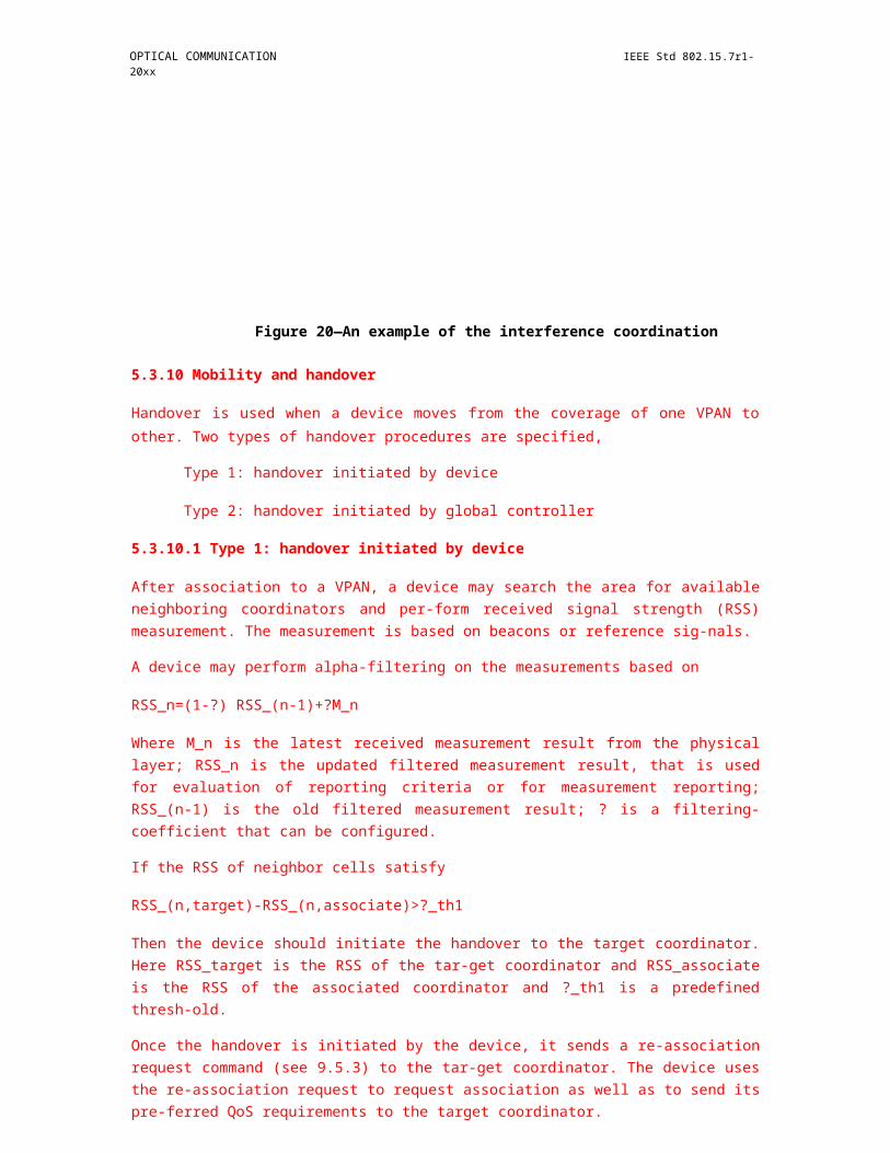
OPTICAL COMMUNICATION IEEE Std 802.15.7r1-20xx
band i band j band i band p band q
powerspectral
powerspectral
intentional transmission unintentional transmissionindicate merged band in MAC capabilities indicate guard band(s) in MAC capabilities,
(channel aggregation) depending on leakage amount
(A) (guard channel)(B)
Figure 65—Concept of aggregation channel and guard channel Figure 1—IEEE802.15.7r1 Frame Control Field Format
If multiple bands are aggregated or multiple optical sources are transmitting simultaneously, the same data shall be sent on all optical sources during the preamble and header during device discovery since it is not known what the receiver capabilities are. The details on channel aggregation and guard channel support are provided in the PHY capabilities information element of the MAC. The criterion used for defining a guard color channel or aggregated channel is based on out-of-band leakage exceeding 20 dB over maximum in-channel value. The transmitting device shall indicate channel aggregation and guard channel support using the PHY capabilities during device discovery and association for bi-directional communication modes.
6.2.x Neighboring VPAN status monitoring
Neighboring VPANs status monitoring procedure allows the coordinator and the devices to detect and maintain neighboring VPANs information. Neighboring VPAN status monitoring maybe performed for the purposes of VPAN maintenance, interference coordination and handover.
Both coordinators and the devices shall participate in the neighboring VPANs status monitoring procedure. The information of neighboring VPANs that can be detected shall be recorded in a neighboring VPANs descriptor list.
Both the coordinator and the devices shall each maintain a local neighboring VPANs descriptor list respectively. The local neighboring VPAN descriptor list is maintained by receiving beacon frames or other frames from the neighboring VPANs. When a beacon frame or any other frame from neighboring VPANs is received for the first time, a new record corresponding to the neighboring VPAN shall be added to the list. The record in the list has an ageing time of macAgeingTime superframes. Whenever a beacon frame or any other frame from a neighboring VPAN corresponding to a record in the list has been received, the device shall update the LastTimeDetected of the record instead of adding a new record. Once the beacon frames or any other frame from a neighboring VPAN corresponding to a record in the list has not been received within the ageing time since last time it was detected, the record corresponding to that neighboring VPAN shall be deleted from the list.
The devices shall update their local neighboring VPANs descriptor list and send a neighboring VPAN report indication command to the coordinator to report its local neighboring VPANs descriptor list whenever any of the following events occurs:
- It has received a beacon frame or any other frames sent by the neighboring coordinators or devices for the first time;
- It has been macLastDetect superframes since the neighboring VPAN was detected last time;- A neighboring VPAN report request command is received by the device from the coordinator;
The coordinator shall update its local neighboring VPAN descriptor list whenever any of the following events occurs:
- It has received a beacon frame or any other frames sent by the neighboring coordinators or devices for the first time;
- It has been macLastDetect superframes since the neighboring VPAN was detected last time;
The coordinator shall also maintain a global neighboring VPAN descriptor list. The global neighboring VPAN descriptor list is maintained and updated by gathering the reported local neighboring VPAN descriptor lists from devices and its own local neighboring VPAN descriptor list. The global neighboring VPANs descriptor list is shown in Table xx.
The coordinator shall update its global neighboring VPAN descriptors list whenever it has received a neighboring VPAN report indication command from devices in the VPAN, or when its own local neighboring VPAN descriptors list has been updated. The coordinator shall also update the global neighboring VPAN descriptors list by deleting the corresponding information if the device which has reported the corresponding information is disassociated from the VPAN.
Table xx Global neighboring VPANs descriptor list
Name Type Valid range Description
Number NeighboringVPANRecords
Integer 0x00-0xff. The number of records of neighboring VPANs that are maintained by the coordinator.
VPANDescriptor [0] Refer to Table yy
The record of the first neighboring VPAN that can be detected by devices.
NumberDetectDevice Integer 0x00-0xff. The number of devices that have detected the neighboring VPAN specified by VPANDescriptor [0]. Assuming the total number is K.
DeviceAddr[0] Integer The short address of the first device that has reported it can detect the neighboring VPAN specified by VPANDescriptor [0].
LinkQuality[0] The RSS at which the first device receives the beacon frame or other frames from the VPAN specified by VPANDescriptor [0].
……
DeviceAddr[K-1] Integer The short address of the Kth device that has reported it can detect the neighboring VPAN specified by VPANDescriptor [0].
LinkQuality[K-1] The RSS at which the Kth device receives the beacon frame or other frames from the VPAN specified by VPANDescriptor [0].
……
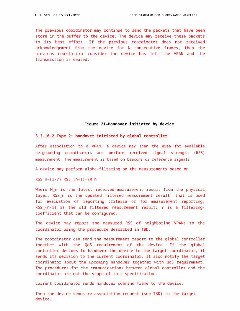
VPANDescriptor [N-1] Refer to Table yy
The record of the Nth neighboring VPAN that can be detected by devices.
NumberDetectDevice Integer 0x00-0xff. The number of devices that have detected the neighboring VPAN specified by VPANDescriptor [N-1]. Assuming the total number is L.
DeviceAddr[0] Integer The short address of the first device that has reported it can detect the neighboring VPAN specified by VPANDescriptor [N-1].
LinkQuality[0] The RSS at which the first device receives the beacon frame or other frames from the VPAN specified by VPANDescriptor [N-1].
……
DeviceAddr[L-1] Integer The short address of the Lth device that has reported it can detect the neighboring VPAN specified by VPANDescriptor [N-1].
LinkQuality[L-1] The RSS at which the Lth device receives the beacon frame or other frames from the VPAN specified by VPANDescriptor [N-1].
6.2.3 Maintaining VPANs
In some instances a situation could occur in which two VPANs exist in the same operating space with the same VPAN identifier. If this conflict happens, the coordinator and its devices shall perform the VPAN identifier conflict resolution procedure.
This procedure is optional for a device.
6.2.3.1 Detection
The VPAN coordinator shall conclude that a VPAN identifier conflict is present if either of the following apply:
— A beacon frame is received by the VPAN coordinator with the VPAN Coordinator subfield, see 6.4.6.1.2, set to one and the VPAN identifier equal to macVPANId.
— A VPAN ID conflict notification command, see 6.7.5, is received by the VPAN coordinator from an associated device on its VPAN.
A device that is associated through the VPAN coordinator (i.e., macAssociatedVPANCoord is set to TRUE) shall conclude that a VPAN identifier conflict is present if the following applies:
— A beacon frame is received by the device with the VPAN Coordinator subfield set to one, the VPAN identifier equal to macVPANId, and an address that is equal to neither macCoordShortAddress nor macCoordExtendedAddress.

Copyright © 2011 IEEE. All rights reserved. 89
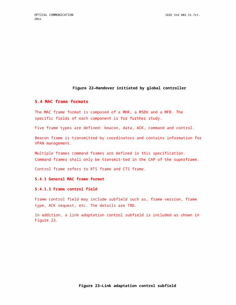
IEEE Std 802.15.7r1-20xx IEEE STANDARD FOR SHORT-RANGE WIRELESS
6.2.3.2 Resolution
On the detection of a VPAN identifier conflict by a device, it shall generate the VPAN ID conflict notification command, defined in 6.7.5, and send it to its coordinator. Since the VPAN ID conflict notification command contains an acknowledgment request (see 6.7.3.1), the coordinator shall confirm its receipt by sending an acknowledgment frame. Once the device has received the acknowledgment frame from the coordinator, the MLME shall issue an MLME -SYNC -LOSS.indication primitive with the LossReason parameter set to VPAN_ID_CONFLICT. If the device does not receive an acknowledgment frame, the MLME shall not inform the next higher layer of the VPAN identifier conflict.
On the detection of a VPAN identifier conflict by the coordinator, the MLME shall issue an MLME-SYNC-LOSS.indication to the next higher layer with the LossReason parameter set to VPAN_ID_CONFLICT. The next higher layer of the coordinator may then perform an active scan and, using the information from the scan, select a new VPAN identifier. The algorithm for selecting a suitable VPAN identifier is out of the scope of this standard. If the next higher layer does select a new VPAN identifier, it may then issue an MLME-START.request with the CoordRealignment parameter set to TRUE in order to realign the VPAN, as described in 6.2.3.3.
6.2.3.3 Realigning a VPAN
If a coordinator receives the MLME-START.request primitive (see 7.3.11.1) with the CoordRealignment parameter set to TRUE, the coordinator shall attempt to transmit a coordinator realignment command containing the new parameters for VPANId, LogicalChannel.
When the coordinator is already transmitting beacons and the CoordRealignment parameter is set to TRUE, the next scheduled beacon shall be transmitted on the current channel using the current superframe configuration, with the frame pending subfield of the frame control field set to one. Immediately following the transmission of the beacon, the coordinator realignment command shall also be transmitted on the current channel using unslotted random access.
When the coordinator is not already transmitting beacons and the CoordRealignment parameter is set to TRUE, the coordinator realignment command shall be transmitted immediately on the current channel using unslotted random access.
If the transmission of the coordinator realignment command fails due to a channel access failure, the MLME shall notify the next higher layer by issuing the MLME -START.confirm primitive with a status of CHANNEL_ACCESS_FAILURE. The next higher layer may then choose to issue the MLME-START.request primitive again.
Upon successful transmission of the coordinator realignment command, the new superframe configuration and channel parameters shall be put into operation as described in 6.2.3.5 at the subsequent scheduled beacon, or immediately if the coordinator is not already transmitting beacons, and the MAC sublayer shall issue the MLME-START.confirm primitive with a status of SUCCESS.
6.2.3.4 Realignment in a VPAN
If a device has received the coordinator realignment command (see 6.7.7) from the coordinator through which it is associated, the MLME shall issue the MLME-SYNC-LOSS.indication primitive with the LossReason parameter set to REALIGNMENT and the VPANId, LogicalChannel, and the security-related parameters set to the respective fields in the coordinator realignment command. The next higher layer of a coordinator may then issue an MLME-START.request primitive with the CoordRealignment parameter set to TRUE. The next higher layer of a device that is not a coordinator may instead change the superframe configuration or channel parameters through use of the MLME-SET.request primitive.
90 Copyright © 20xx IEEE. All rights reserved.

OPTICAL COMMUNICATION IEEE Std 802.15.7r1-20xx
6.2.3.5 Updating superframe configuration and channel PIB attributes
To update the superframe configuration and channel attributes, the MLME shall assign values from the MLME-START.request primitive parameters to the appropriate PIB attributes. The MLME shall set macBeaconOrder to the value of the BeaconOrder parameter. If macBeaconOrder is equal to 15, the MLME will also set macSuperframeOrder to 15. In this case, this primitive configures a nonbeacon-enabled VPAN. If macBeaconOrder is less than 15, the MAC sublayer will set macSuperframeOrder to the value of the SuperframeOrder parameter. The MAC sublayer shall also update macVPANId with the value of the VPANId parameter and update phyCurrentChannel with the values of the LogicalChannel parameters by issuing the PLME-SET.request primitive.
6.2.4 Association and disassociation
This subclause specifies the procedures for association and disassociation.
6.2.4.1 Association
A device shall attempt to associate only after having first performed a MAC sublayer reset, by issuing the MLME-RESET.request primitive with the SetDefaultPIB parameter set to TRUE, and then having completed either an active channel scan, see 6.2.2.1.1, or a passive channel scan as shown in 6.2.2.1.2. The results of the channel scan would have then been used to choose a suitable VPAN. The algorithm for selecting a suitable VPAN with which to associate from the list of VPAN descriptors returned from the channel scan procedure is out of the scope of this standard.
Following the selection of a VPAN with which to associate, the next higher layers shall request through the MLME-ASSOCIATE.request primitive that the MLME configures the following PHY and MAC PIB attributes to the values necessary for association:
— phyCurrentChannel shall be set equal to the LogicalChannel parameter of the MLME-ASSOCIATE.request primitive.
— macVPANId shall be set equal to the CoordVPANId parameter of the MLME-ASSOCIATE.request primitive.
— macCoordExtendedAddress or macCoordShortAddress, depending on which is known from the beacon frame from the coordinator through which it wishes to associate, shall be set equal to the CoordAddress parameter of the MLME-ASSOCIATE.request primitive.
A coordinator shall allow association only if macAssociationPermit is set to TRUE. Similarly, a device should attempt to associate only with a VPAN through a coordinator that is currently allowing association, as indicated in the results of the scanning procedure. If a coordinator with macAssociationPermit set to FALSE receives an association request command from a device, the command shall be ignored.
A coordinator receives the additional beacon request commands from a device may start to send additional beacons in each superframe from the next superframe in addition to the original beacons. The coordinator shall allocate a GTS in the CFP to transmit the additional beacon frames. The content of the additional beacon frame shall be the same as the beacon sent in the BP in the same superframe except the beacon type and shall be modulated on the minimum bandwidth. The BeaconType field in the beacon frame can be used to identify the type of the beacons. If the coordinator receives another additional beacon request command from the same device, it may allocate a different GTS to transmit in the CFP to transmit additional beacon frames from the next superframe. If the coordinator receives an association request from the device that sent the additional beacon request command within [TBD ms], it shall handle the association request. If the coordinator does not receive any association request from the device that sent the additional beacon request command within [TBD ms], it may stop transmit the additional beacons and only transmit the original beacons.
In order to optimize the association procedure on a beacon-enabled VPAN, a device may begin tracking the beacon of the coordinator through which it wishes to associate. This is achieved by the next higher layer issuing the MLME-SYNC.request primitive with the TrackBeacon parameter set to TRUE.
A device that is instructed to associate with a VPAN, through the MLME-ASSOCIATE.request primitive, shall try to associate only with an existing VPAN and shall not attempt to start its own VPAN.
The MAC sublayer of an unassociated device shall initiate the association procedure by sending an association request command, see 6.7.1, to the coordinator of an existing VPAN; if the association request command cannot be sent due to a channel access failure, the MAC sublayer shall notify the next higher layer. Because the association request command contains an acknowledgment request (see 6.7.1.1), the coordinator shall confirm its receipt by sending an acknowledgment frame.
Copyright © 2011 IEEE. All rights reserved. 91

IEEE Std 802.15.7r1-20xx IEEE STANDARD FOR SHORT-RANGE WIRELESS
The acknowledgment to an association request command does not mean that the device has associated. The next higher layer of the coordinator needs time to determine whether the current resources available on the VPAN are sufficient to allow another device to associate. The next higher layer should make this decision within macResponseWaitTime optical clocks. If the next higher layer of the coordinator finds that the device was previously associated on its VPAN, all previously obtained device -specific information should be removed. If sufficient resources are available, the next higher layer should allocate a 16-bit short address to the device, and the MAC sublayer shall generate an association response command, see 6.7.2, containing the new address and a status indicating a successful association. If sufficient resources are not available, the next higher layer of the coordinator should inform the MAC sublayer, and the MLME shall generate an association response command containing a status indicating a failure as shown in Table 13. The association response command shall be sent to the device requesting association using indirect transmission, i.e., the association response command frame shall be added to the list of pending transactions stored on the coordinator and extracted at the discretion of the device concerned using the method described in 6.2.7.3.
If the allocate address subfield of the capability information field (see 6.7.19.1.1) of the association request command is set to one, the next higher layer of the coordinator shall allocate a 16- bit address with a range depending on the addressing mode supported by the coordinator, as described in Table 3. If the Allocate Address subfield of the association request command is set to zero, the 16-bit short address shall be equal to 0xfffe. A short address of 0xfffe is a special case that indicates that the device has associated, but has not been allocated a short address by the coordinator. In this case, the device shall use only its 64-bit extended address to operate on the network.
On receipt of the acknowledgment to the association request command, the device shall wait for at most macResponseWaitTime optical clocks for the coordinator to make its association decision; the PIB attribute macResponseWaitTime is a network-topology-dependent parameter and may be set to match the specific requirements of the network that a device is trying to join. If the device is tracking the beacon, it shall attempt to extract the association response command from the coordinator whenever it is indicated in the beacon frame. If the device is not tracking the beacon, it shall attempt to extract the association response command from the coordinator after macResponseWaitTime optical clocks. If the device does not extract an association response command frame from the coordinator within macResponseWaitTime optical clocks, the MLME shall issue the MLME-ASSOCIATE.confirm primitive with a status of NO_DATA, and the association attempt shall be deemed a failure. In this case, the next higher layer shall terminate any tracking of the beacon. This is achieved by issuing the MLME-SYNC.request primitive with the TrackBeacon parameter set to FALSE.
The MLME-ASSOCIATE.response and the subsequent Association response (see 6.7.2) also contain information about what capabilities the device and the coordinator will and will not use during future communication.
Because the association response command contains an acknowledgment request (see 6.7.2.1), the device requesting association shall confirm its receipt by sending an acknowledgment frame. If the Association Status field of the command indicates that the association was successful, the device shall store the address contained in the 16-bit Short Address field of the command in macShortAddress; communication on the VPAN using this short address shall depend on its range, as described in Table 3. If the original beacon selected for association following a scan contained the short address of the coordinator, the extended address of the coordinator, contained in the MHR of the association response command frame, shall be stored in macCoordExtendedAddress.
If the Association Status field of the command indicates that the association was unsuccessful, the device shall set macVPANId to the default value (0xffff).
92 Copyright © 20xx IEEE. All rights reserved.
OPTICAL COMMUNICATION IEEE Std 802.15.7r1-20xx
Table 3—Usage of the 16-bit short address
Value of macShortAddress Description
0x0000–0xfffd If a source address is included, the device shall use short source addressingmode for beacon and data frames and the appropriate source addressingmode specified in 6.7 for MAC command frames.
0xfffe If a source address is included, the device shall use extended sourceaddressing mode for beacon and data frames and the appropriate sourceaddressing mode specified in 6.7 for MAC command frames.
0xffff The device is not associated and, therefore, shall not perform any dataframe communication. The device shall use the appropriate sourceaddressing mode specified in 6.7 for MAC command frames.
6.2.4.2 Disassociation
The disassociation procedure is initiated by the next higher layer by issuing the MLME-DISASSOCIATE.request primitive to the MLME.
When a coordinator wants one of its associated devices to leave the VPAN, the MLME of the coordinator shall send the disassociation notification command in the manner specified by the TxIndirect parameter of the MLME-DISASSOCIATE.request primitive previously sent by the next higher layer. If TxIndirect is TRUE, the MLME of the coordinator shall send the disassociation notification command to the device using indirect transmission, i.e., the disassociation notification command frame shall be added to the list of pending transactions stored on the coordinator and extracted at the discretion of the device concerned using the method described in 6.2.7.3. If the command frame is not successfully extracted by the device, the coordinator should consider the device disassociated. Otherwise, the MLME shall send the disassociation notification command to the device directly. In this case, if the disassociation notification command cannot be sent due to a channel access failure, the MAC sublayer shall notify the next higher layer.
Because the disassociation command contains an acknowledgment request (see 6.7.3.1), the receiving device shall confirm its receipt by sending an acknowledgment frame. If the direct or indirect transmission fails, the coordinator should consider the device disassociated.
If an associated device wants to leave the VPAN, the MLME of the device shall send a disassociation notification command to its coordinator. If the disassociation notification command cannot be sent due to a channel access failure, the MAC sublayer shall notify the next higher layer. Because the disassociation command contains an acknowledgment request (see 6.7.3.1), the coordinator shall confirm its receipt by sending an acknowledgment frame. However, even if the acknowledgment is not received, the device should consider itself disassociated.
If the source address contained in the disassociation notification command is equal to macCoord-ExtendedAddress, the device should consider itself disassociated. If the command is received by a coordinator and the source is not equal to macCoordExtendedAddress, it shall verify that the source address corresponds to one of its associated devices; if so, the coordinator should consider the device disassociated. If none of the conditions for disassociation are satisfied, the command shall be ignored.
An associated device shall disassociate itself by removing all references to the VPAN; the MLME shall set macVPANId, macShortAddress, macAssociatedVPANCoord, macCoordShortAddress and macCoordExtendedAddress to the default values. The next higher layer of a coordinator should disassociate a device by removing all references to that device.
The next higher layer of the requesting device shall be notified of the result of the disassociation procedure through the MLME-DISASSOCIATE.confirm primitive.
Copyright © 2011 IEEE. All rights reserved. 93

IEEE Std 802.15.7r1-20xx IEEE STANDARD FOR SHORT-RANGE WIRELESS
6.2.5 Synchronization
This subclause specifies the procedures for coordinators to generate beacon frames and for devices to synchronize with a coordinator. For VPANs supporting beacons, synchronization is performed by receiving and decoding the beacon frames. For VPANs not supporting beacons, synchronization is performed by polling the coordinator for data.
6.2.5.1 Synchronization with beacons
All devices operating on a beacon -enabled VPAN (i.e., macBeaconOrder < 15) shall be able to acquire beacon synchronization in order to detect any pending messages or to track the beacon. Devices shall be permitted to acquire beacon synchronization only with beacons containing the VPAN identifier specified in macVPANId. If macVPANId specifies the broadcast VPAN identifier (0xffff), a device shall not attempt to acquire beacon synchronization.
A device is instructed to attempt to acquire the beacon through the MLME-SYNC.request primitive. If tracking is specified in the MLME- SYNC.request primitive, the device shall attempt to acquire the beacon and keep track of it by regular and timely activation of its receiver. If tracking is not specified, the device shall either attempt to acquire the beacon only once or terminate the tracking after the next beacon if tracking was enabled through a previous request.
To acquire beacon synchronization, a device shall enable its receiver and search for at most [aBaseSuperframeDuration (2n + 1)] optical clocks, where n is the value of macBeaconOrder. If a beacon frame containing the current VPAN identifier of the device is not received, the MLME shall repeat this search. Once the number of missed beacons reaches aMaxLostBeacons, the MLME shall notify the next higher layer by issuing the MLME-SYNC-LOSS.indication primitive with a loss reason ofBEACON_LOSS.
The MLME shall timestamp each received beacon frame at the same symbol boundary within each frame, the location of which is described by the macTimeStampOffset attribute. The position shall be the same as that used in the timestamp of the outgoing beacon frame, stored in macBeaconTxTime. The timestamp value shall be that of the local clock of the device at this position. The timestamp is intended to be a relative time measurement that may or may not be made absolute, at the discretion of the implementer.
If a protected beacon frame is received (i.e., the Security Enabled subfield in the frame control field is set to one), the device shall attempt to unsecure the beacon frame using the unsecuring process described in 8.2.3.
If the status from the unsecuring process is not SUCCESS, the MLME shall issue an MLME- COMM-STATUS.indication primitive with the status parameter set to the status from the unsecuring process, indicating the error.
The security-related elements of the VPAN descriptor corresponding to the beacon (see Table 40) shall be set to the corresponding parameters returned by the unsecuring process. The SecurityFailure element of the VPAN descriptor shall be set to SUCCESS if the status from the unsecuring process is SUCCESS and set to one of the other status codes indicating an error in the security processing otherwise.
If a beacon frame is received, the MLME shall discard the beacon frame if the Source Address and the Source VPAN Identifier fields of the MHR of the beacon frame do not match the coordinator source address (macCoordShortAddress or macCoordExtendedAddress, depending on the addressing mode) and the identifier of the device (macVPANId).
If a valid beacon frame is received and macAutoRequest is set to FALSE, the MLME shall indicate the beacon parameters to the next higher layer by issuing the MLME-BEACON-NOTIFY.indication primitive. If a beacon frame is received and macAutoRequest is set to TRUE, the MLME shall first issue the MLME-
94 Copyright © 20xx IEEE. All rights reserved.

OPTICAL COMMUNICATION IEEE Std 802.15.7r1-20xx
BEACON- NOTIFY.indication primitive if the beacon contains any payload. The MLME shall then compare its address with those addresses in the Address List field of the beacon frame. If the Address List field contains the 16-bit short or 64-bit extended address of the device and the source VPAN identifier matches macVPANId, the MLME shall follow the procedure for extracting pending data from the coordinator as shown in 6.2.7.3.
If beacon tracking is activated, the MLME shall enable its receiver at a time prior to the next expected beacon frame transmission, i.e., just before the known start of the next superframe. If the number of consecutive beacons missed by the MLME reaches aMaxLostBeacons, the MLME shall respond with the MLME-SYNC-LOSS.indication primitive with a loss reason of BEACON_LOST.
6.2.5.2 Synchronization without beacons
All devices operating on a nonbeacon -enabled VPAN (macBeaconOrder = 15) shall be able to poll the coordinator for data at the discretion of the next higher layer.
A device is instructed to poll the coordinator when the MLME receives the MLME-POLL.request primitive. On receipt of this primitive, the MLME shall follow the procedure for extracting pending data from the coordinator as shown in 6.2.7.3.
6.2.6 Transaction handling
Transactions can be instigated from the devices themselves rather than from the coordinator. In other words, either the coordinator needs to indicate in its beacon when messages are pending for devices or the devices themselves need to poll the coordinator to determine whether they have any messages pending. Such transfers are called indirect transmissions.
The coordinator shall begin handling a transaction on receipt of an indirect transmission request either via the MCPS-DATA.request primitive or via a request from the MLME to send a MAC command instigated by a primitive from the next higher layer, such as the MLME- ASSOCIATE.response primitive as shown in 7.3.1.3. On completion of the transaction, the MAC sublayer shall indicate a status value to the next higher layer. If a request primitive instigated the indirect transmission, the corresponding confirm primitive shall be used to convey the appropriate status value. Conversely, if a response primitive instigated the indirect transmission, the MLME-COMM-STATUS.indication primitive shall be used to convey the appropriate status value. The MLME-COMM-STATUS.indication primitive can be related to its corresponding response primitive by examining the Destination Address field.
The information contained in the indirect transmission request forms a transaction, and the coordinator shall be capable of storing at least one transaction. On receipt of an indirect transmission request, if there is no capacity to store another transaction, the MAC sublayer shall indicate to the next higher layer a status of TRANSACTION_OVERFLOW in the appropriate corresponding primitive.
If the coordinator is capable of storing more than one transaction, it shall ensure that all the transactions for the same device are sent in the order in which they arrived at the MAC sublayer. For each transaction sent, if another exists for the same device, the MAC sublayer shall set its frame pending subfield to one, indicating the additional pending data.
Each transaction shall persist in the coordinator for at most macTransactionPersistenceTime. If the transaction is not successfully extracted by the appropriate device within this time, the transaction information shall be discarded and the MAC sublayer shall indicate to the next higher layer a status of TRANSACTION_EXPIRED in the appropriate corresponding primitive. In order to be successfully extracted, an acknowledgment shall be received if one was requested.
Copyright © 2011 IEEE. All rights reserved. 95

IEEE Std 802.15.7r1-20xx IEEE STANDARD FOR SHORT-RANGE WIRELESS
If the transaction was successful, the transaction information shall be discarded, and the MAC sublayer shall indicate to the next higher layer a status of SUCCESS in the appropriate corresponding primitive.
If the coordinator transmits beacons, it shall list the addresses of the devices to which each transaction is associated in the Address List field and indicate the number of addresses in the Pending Address Specification field of the beacon frame. If the coordinator is able to store more than seven pending transactions, it shall indicate them in its beacon on a first-come-first -served basis, ensuring that the beacon frame contains at most seven addresses. For transactions requiring a GTS, the coordinator shall not add the address of the recipient to its list of pending addresses in the beacon frame. Instead it shall transmit the transaction in the GTS allocated for the device as shown in 6.2.8.3.
On a beacon-enabled VPAN, if there is a transaction pending for the broadcast address, the frame pending subfield of the frame control field in the beacon frame shall be set to one, and the pending message shall be transmitted immediately following the beacon using the unslotted random access algorithm. If there is a second message pending for the broadcast address, its transmission shall be delayed until the following superframe. Only one broadcast message shall be allowed to be sent indirectly per superframe.
On a beacon-enabled VPAN, a device that receives a beacon containing its address in the list of pending addresses shall attempt to extract the data from the coordinator. On a nonbeacon-enabled VPAN, a device shall attempt to extract the data from the coordinator on receipt of the MLME-POLL.request primitive. The procedure for extracting pending data from the coordinator is described in 6.2.7.3. If a device receives a beacon with the frame pending subfield set to one, it shall leave its receiver enabled for up to macMaxFrameTotalWaitTime optical clocks to receive the broadcast data frame from the coordinator.
6.2.7 Transmission, reception, and acknowledgment
This subclause describes the fundamental procedures for transmission, reception, and acknowledgment.
6.2.7.1 Transmission
Each device shall store its current data -sequence number (DSN) value in the MAC PIB attribute macDSN and initialize it to a random value; the algorithm for choosing a random number is out of the scope of this standard. Each time a data or a MAC command frame is generated, the MAC sublayer shall copy the value of macDSN into the Sequence Number field of the MHR of the outgoing frame and then increment it by one. Each device shall generate exactly one DSN regardless of the number of unique devices with which it wishes to communicate. The value of macDSN shall be permitted to roll over.
Each coordinator shall store its current beacon-sequence number (BSN) value in the MAC PIB attribute macBSN and initialize it to a random value; the algorithm for choosing a random number is out of the scope of this standard. Each time a beacon frame is generated, the MAC sublayer shall copy the value of macBSN into the Sequence Number field of the MHR of the outgoing frame and then increment it by one. The value of macBSN shall be permitted to roll over.
It should be noted that both the DSN and BSN are 8-bit values and, therefore, have limited use to the next higher layer (e.g., in the case of the DSN, in detecting retransmitted frames).
The Source Address field, if present, shall contain the address of the device sending the frame. When a device has associated and has been allocated a 16-bit short address (i.e., macShortAddress is not equal to 0xfffe or 0xffff), it shall use that address in preference to its 64-bit extended address (i.e., aExtendedAddress) wherever possible. When a device has not yet associated to a VPAN or macShortAddress is equal to 0xffff, it shall use its 64-bit extended address in all communications requiring the Source Address field. If the Source Address field is not present, the originator of the frame shall be assumed to be the coordinator, and the Destination Address field shall contain the address of the recipient.
96 Copyright © 20xx IEEE. All rights reserved.
OPTICAL COMMUNICATION IEEE Std 802.15.7r1-20xx
The Destination Address field, if present, shall contain the address of the intended recipient of the frame, which may be either a 16-bit short address or a 64-bit extended address. If the Destination Address field is not present, the recipient of the frame shall be assumed to be the coordinator, and the Source Address field shall contain the address of the originator.
If both destination and source addressing information is present, the MAC sublayer shall compare the destination and source VPAN identifiers. If the VPAN identifiers are identical, the VPAN ID Compression subfield of the frame control field shall be set to one, and the source VPAN identifier shall be omitted from the transmitted frame. If the VPAN identifiers are different, the VPAN ID Compression subfield of the frame control field shall be set to zero, and both Destination VPAN Identifier and Source VPAN Identifier fields shall be included in the transmitted frame. If only either the destination or the source addressing information is present, the VPAN ID Compression subfield of the frame control field shall be set to zero, and the VPAN identifier field of the single address shall be included in the transmitted frame.
If the frame is to be transmitted on a beacon-enabled VPAN, the transmitting device shall attempt to find the beacon before transmitting. If the beacon is not being tracked, as shown in 6.2.5.1, and hence the device does not know where the beacon will appear, it shall enable its receiver and search for at most
[aBaseSuperframeDuration (2 n + 1)] optical clocks, where n is the value of macBeaconOrder, in order to find the beacon. If the beacon is not found after this time, the device shall transmit the frame following the successful application of the unslotted version of the random access algorithm as shown in 6.2.1.8. Once the beacon has been found, either after a search or due to its being tracked, the frame shall be transmitted in the appropriate portion of the superframe. Transmissions in the CAP shall follow a successful application of the slotted version of the random access algorithm, see 6.2.1.8, and transmissions in a GTS shall not use any random access.
If the frame is to be transmitted on a nonbeacon-enabled VPAN, the frame shall be transmitted following the successful application of the unslotted version of the random access algorithm as shown in 6.2.1.8.
For either a beacon-enabled VPAN or a nonbeacon -enabled VPAN, if the transmission is direct and originates due to a primitive issued by the next higher layer and the access algorithm fails, the next higher layer shall be notified. If the transmission is indirect and the access algorithm fails, the frame shall remain in the transaction queue until it is requested again and successfully transmitted or until the transaction expires.
The device shall process the frame using the outgoing frame security procedure described in 8.2.1.
If the status from the outgoing frame security procedure is not SUCCESS, the MLME shall issue the corresponding confirm or MLME-COMM-STATUS.indication primitive with the status parameter set to the status from the outgoing frame security procedure, indicating the error.
To transmit the frame, the MAC sublayer shall first enable the transmitter by issuing the PLME-SET-TRX-STATE.request primitive with a state of TX_ON to the PHY. On receipt of the PLME-SET-TRX-STATE.confirm primitive with a status of either SUCCESS or TX_ ON, the constructed frame shall then be transmitted by issuing the PD-DATA.request primitive. Finally, on receipt of the PD-DATA.confirm primitive, the MAC sublayer shall disable the transmitter by issuing the PLME-SET-TRX-STATE.request primitive with a state of RX_ON or TRX _OFF to the PHY, depending on whether the receiver is to be enabled following the transmission. In the case where the Acknowledgment Request subfield of the frame control field is set to one, the MAC sublayer shall enable the receiver immediately following the transmission of the frame by issuing the PLME-SET-TRX-STATE.request primitive with a state of RX_ON to the PHY.
6.2.7.2 Reception and rejection
Each device may choose whether the MAC sublayer is to enable its receiver during idle periods. During these idle periods, the MAC sublayer shall still service transceiver task requests from the next higher layer.
Copyright © 2011 IEEE. All rights reserved. 97

IEEE Std 802.15.7r1-20xx IEEE STANDARD FOR SHORT-RANGE WIRELESS
A transceiver task shall be defined as a transmission request with acknowledgment reception, if required, or a reception request. On completion of each transceiver task, the MAC sublayer shall request that the PHY enables or disables its receiver, depending on the values of macBeaconOrder and macRxOnWhenIdle. If macBeaconOrder is less than 15, the value of macRxOnWhenIdle shall be considered relevant only during idle periods of the CAP of the incoming superframe. If macBeaconOrder is equal to 15, the value of macRxOnWhenIdle shall be considered relevant at all times.
A device with its receiver enabled will be able to receive and decode transmissions from all devices complying with this standard that are currently operating on the same channel and are in its operating space, along with interference from other sources. The MAC sublayer shall, therefore, be able to filter incoming frames and present only the frames that are of interest to the upper layers.
The MAC sublayer shall discard all received frames that do not contain a correct value in their FCS field in the MFR (see 6.4.1.9). The FCS field shall be verified on reception by recalculating the purported FCS over the MHR and MSDU of the received frame and by subsequently comparing this value with the received FCS field. The FCS field of the received frame shall be considered to be correct if these values are the same and incorrect otherwise.
The MAC sublayer shall accept only frames that satisfy all of the following filtering requirements:
— The Frame Type subfield shall not contain a reserved frame type.— If a destination VPAN identifier is included in the frame, it shall match macVPANId or shall be the
broadcast VPAN identifier (0xffff).— If a short destination address is included in the frame, it shall match either macShortAddress or the
broadcast address (0xffff). Otherwise, if an extended destination address is included in the frame, it shall match aExtendedAddress.
— If the frame type indicates that the frame is a beacon frame, the source VPAN identifier shall match macVPANId unless macVPANId is equal to 0xffff, in which case the beacon frame shall be accepted regardless of the source VPAN identifier.
— If only source addressing fields are included in a data or MAC command frame, the frame shall be accepted only if the device is the coordinator and the source VPAN identifier matches macVPANId.
If any of the third-level filtering requirements are not satisfied, the MAC sublayer shall discard the incoming frame without processing it further. If all of the third-level filtering requirements are satisfied, the frame shall be considered valid and processed further. For valid frames that are not broadcast, if the Frame Type subfield indicates a data or MAC command frame and the Acknowledgment Request subfield of the frame control field is set to one, the MAC sublayer shall send an acknowledgment frame. Prior to the transmission of the acknowledgment frame, the sequence number included in the received data or MAC command frame shall be copied into the Sequence Number field of the acknowledgment frame. This step will allow the transaction originator to know that it has received the appropriate acknowledgment frame.
If the VPAN ID Compression subfield of the frame control field is set to one and both destination and source addressing information is included in the frame, the MAC sublayer shall assume that the omitted Source VPAN Identifier field is identical to the Destination VPAN Identifier field.
The device shall process the frame using the incoming frame security procedure described in 8.2.3.
If the status from the incoming frame security procedure is not SUCCESS, the MLME shall issue the corresponding confirm or MLME -COMM- STATUS.indication primitive with the status parameter set to the status from the incoming frame security procedure, indicating the error, and with the security-related parameters set to the corresponding parameters returned by the unsecuring process.
98 Copyright © 20xx IEEE. All rights reserved.
OPTICAL COMMUNICATION IEEE Std 802.15.7r1-20xx
If the valid frame is a data frame, the MAC sublayer shall pass the frame to the next higher layer. This is achieved by issuing the MCPS-DATA.indication primitive containing the frame information. The security-related parameters of the MCPS-DATA.indication primitive shall be set to the corresponding parameters returned by the unsecuring process.
If the valid frame is a MAC command or beacon frame, it shall be processed by the MAC sublayer accordingly, and a corresponding confirm or indication primitive may be sent to the next higher layer. The security-related parameters of the corresponding confirm or indication primitive shall be set to the corresponding parameters returned by the unsecuring process.
6.2.7.3 Extracting pending data from a coordinator
A device on a beacon-enabled VPAN can determine whether any frames are pending for it by examining the contents of the received beacon frame, as described in 6.2.5.1. If the address of the device is contained in the Address List field of the beacon frame and macAutoRequest is TRUE, the MLME of the device shall send a data request command, see 6.7.4, to the coordinator during the CAP with the Acknowledgment Request subfield of the frame control field set to one; the only exception to this is if the beacon frame is received while performing an active or passive scan as shown in 6.2.3.1. There are two other cases for which the MLME shall send a data request command to the coordinator. The first case is when the MLME receives the MLME-POLL.request primitive. In the second case, a device may send a data request command macResponseWaitTime optical clocks after the acknowledgment to a request command frame, such as during the association procedure. If the data request is intended for the coordinator, the destination address information may be omitted.
If the data request command originated from an MLME -POLL.request primitive, the MLME shall perform the security process on the data request command based on the SecurityLevel, KeyIdMode, KeySource, and KeyIndex parameters of the MLME-POLL.request primitive, according to 8.2.1. Otherwise, the MLME shall perform the security process on the data request command based on the macAutoRequestSecurityLevel, macAutoRequestKeyIdMode, macAutoRequestKeySource, and macAutoRequestKeyIndex PIB attributes, according to 8.2.1.
On successfully receiving a data request command, the coordinator shall send an acknowledgment frame, thus confirming its receipt. If the coordinator has enough time to determine whether the device has a frame pending before sending the acknowledgment frame (see 6.2.7.4.2), it shall set the frame pending subfield of the frame control field of the acknowledgment frame accordingly to indicate whether a frame is actually pending for the device. If this is not possible, the coordinator shall set the frame pending subfield of the acknowledgment frame to one.
On receipt of the acknowledgment frame with the frame pending subfield set to zero, the device shall conclude that there are no data pending at the coordinator.
On receipt of the acknowledgment frame with the frame pending subfield set to one, a device shall enable its receiver for at most macMaxFrameTotalWaitTime CAP optical clocks in a beacon-enabled VPAN, or in a nonbeacon-enabled VPAN, to receive the corresponding data frame from the coordinator. If there is an actual data frame pending within the coordinator for the requesting device, the coordinator shall send the frame to the device using one of the mechanisms described in this subclause. If there is no data frame pending for the requesting device, the coordinator shall send a data frame without requesting acknowledgment to the device containing a zero length payload, indicating that no data are present, using one of the mechanisms described in this subclause.
The data frame following the acknowledgment of the data request command shall be transmitted using one of the following mechanisms:
Copyright © 2011 IEEE. All rights reserved. 99

IEEE Std 802.15.7r1-20xx IEEE STANDARD FOR SHORT-RANGE WIRELESS
— Without using slotted random access, if the MAC sublayer can commence transmission of the data frame between aTurnaroundTime-RX-TX and (aTurnaroundTime-RX-TX + aUnitBackoffPeriod) optical clocks, on a backoff slot boundary, and there is time remaining in the CAP for the message, appropriate IFS, and acknowledgment as defined in 10.5.1. If a requested acknowledgment frame is not received following this data frame, the process shall begin anew following the receipt of a new data request command.
— Using slotted random access, otherwise.
If the requesting device does not receive a data frame from the coordinator within macMaxFrameTotalWaitTime CAP optical clocks in a beacon-enabled VPAN, or in a nonbeacon-enabled VPAN, or if the requesting device receives a data frame from the coordinator with a zero length payload, it shall conclude that there are no data pending at the coordinator. If the requesting device does receive a data frame from the coordinator, it shall send an acknowledgment frame, if requested, thus confirming receipt.
If the frame pending subfield of the frame control field of the data frame received from the coordinator is set to one, the device still has more data pending with the coordinator. In this case it may extract the data by sending a new data request command to the coordinator.
6.2.7.4 Use of acknowledgments and retransmissions
A data or MAC command frame shall be sent with the Acknowledgment Request subfield of its frame control field set appropriately for the frame. A beacon or acknowledgment frame shall always be sent with the Acknowledgment Request subfield set to zero. Similarly, any frame that is broadcast shall be sent with its Acknowledgment Request subfield set to zero.
6.2.7.4.1 No acknowledgment
A frame transmitted with its Acknowledgment Request subfield set to zero shall not be acknowledged by its intended recipient. The originating device shall assume that the transmission of the frame was successful.
The message sequence chart in Figure 66 shows the scenario for transmitting a single frame of data from an originator to a recipient without requiring an acknowledgment. In this case, the originator transmits the data frame with the Acknowledgment Request (AR) subfield of the frame control field equal to zero.
originator next originator recipient recipient nexthigher layer MAC MAC higher layer
MCPS-DATA.request (AR=0)Data (AR=0)
MCPS-DATA.indicationMCPS-DATA.confirm
Figure 66—Successful data transmission without an acknowledgment
6.2.7.4.2 Acknowledgment
A frame transmitted with the Acknowledgment Request subfield of its frame control field set to one shall be acknowledged by the recipient. If the intended recipient correctly receives the frame, it shall generate and
100 Copyright © 20xx IEEE. All rights reserved.

OPTICAL COMMUNICATION IEEE Std 802.15.7r1-20xx
send an acknowledgment frame containing the same DSN from the data or MAC command frame that is being acknowledged.
The transmission of an acknowledgment frame in a nonbeacon-enabled VPAN or in the CFP shall commence aTurnaroundTime- RX-TXoptical clocks after the last optical clock of the data or MAC command frame. The transmission of an acknowledgment frame in the CAP shall commence either aTurnaroundTime-RX-TX optical clocks after the reception of the last optical clock of the data or MAC command frame or at a backoff slot boundary. In the latter case, the transmission of an acknowledgment frame shall commence between aTurnaroundTime- RX-TX and (aTurnaroundTime-RX-TX + aUnitBackoffPeriod) optical clocks after the reception of the last optical clock of the data or MAC command frame. The constants aTurnaroundTime-RX-TX and aTurnaroundTime-TX-RX are defined in Table 124.
The message sequence chart in Figure 67 shows the scenario for transmitting a single frame of data from an originator to a recipient with an acknowledgment. In this case, the originator indicates to the recipient that it requires an acknowledgment by transmitting the data frame with the Acknowledgment Request (AR) subfield of the frame control field set to one.
originator next originator recipient recipient nexthigher layer MAC MAC higher layer
MCPS-DATA.request (AR=1)data (AR=1)
acknowledgmentMCPS-DATA.indication
MCPS-DATA.confirm
Figure 67—Successful data transmission with an acknowledgment
6.2.7.4.3 Retransmissions
A device that sends a frame with the Acknowledgment Request subfield of its frame control field set to zero shall assume that the transmission was successfully received and shall hence not perform the retransmission procedure.
A device that sends a data or MAC command frame with its Acknowledgment Request subfield set to one shall wait for at most macAckWaitDuration optical clocks for the corresponding acknowledgment frame to be received. If an acknowledgment frame is received within macAckWaitDuration optical clocks and contains the same DSN as the original transmission, the transmission is considered successful, and no further action regarding retransmission shall be taken by the device. If an acknowledgment is not received within macAckWaitDuration optical clocks or an acknowledgment is received containing a DSN that was not the same as the original transmission, the device shall conclude that the single transmission attempt has failed.
If a single transmission attempt has failed and the transmission was indirect, the coordinator shall not retransmit the data or MAC command frame. Instead, the frame shall remain in the transaction queue of the coordinator and can only be extracted following the reception of a new data request command. If a new data request command is received, the originating device shall transmit the frame using the same DSN as was used in the original transmission.
Copyright © 2011 IEEE. All rights reserved. 101

IEEE Std 802.15.7r1-20xx IEEE STANDARD FOR SHORT-RANGE WIRELESS
If a single transmission attempt has failed and the transmission was direct, the device shall repeat the process of transmitting the data or MAC command frame and waiting for the acknowledgment, up to a maximum of macMaxFrameRetries times. The retransmitted frame shall contain the same DSN as was used in the original transmission. Each retransmission shall only be attempted if it can be completed within the same portion of the superframe, i.e., the CAP or a GTS in which the original transmission was attempted. If this timing is not possible, the retransmission shall be deferred until the same portion in the next superframe. If an acknowledgment is still not received after macMaxFrameRetries retransmissions, the MAC sublayer shall assume the transmission has failed and notify the next higher layer of the failure.
6.2.7.5 Transmission scenarios
Due to the imperfect nature of the wireless medium, a transmitted frame does not always reach its intended destination. Figure 68 illustrates three different data transmission scenarios:
— Successful data transmission. The originator MAC sublayer transmits the data frame to the recipient via the PHY data service. In waiting for an acknowledgment, the originator MAC sublayer starts a timer that will expire after macAckWaitDuration optical clocks. The recipient MAC sublayer receives the data frame, sends an acknowledgment back to the originator, and passes the data frame to the next higher layer. The originator MAC sublayer receives the acknowledgment from the recipient before its timer expires and then disables and resets the timer. The data transfer is now complete, and the originator MAC sublayer issues a success confirmation to the next higher layer.
— Lost data frame. The originator MAC sublayer transmits the data frame to the recipient via the PHY data service. In waiting for an acknowledgment, the originator MAC sublayer starts a timer that will expire after macAckWaitDuration optical clocks. The recipient MAC sublayer does not receive the data frame and so does not respond with an acknowledgment. The timer of the originator MAC sublayer expires before an acknowledgment is received; therefore, the data transfer has failed. If the transmission was direct, the originator retransmits the data, and this entire sequence may be repeated up to a maximum of macMaxFrameRetries times; if a data transfer attempt fails a total of (1 + macMaxFrameRetries) times, the originator MAC sublayer will issue a failure confirmation to the next higher layer. If the transmission was indirect, the data frame will remain in the transaction queue until either another request for the data is received and correctly acknowledged or until macTransactionPersistenceTime is reached. If macTransactionPersistenceTime is reached, the transaction information will be discarded, and the MAC sublayer will issue a failure confirmation to the next higher layer.
— Lost acknowledgment frame. The originator MAC sublayer transmits the data frame to the recipient via the PHY data service. In waiting for an acknowledgment, the originator MAC sublayer starts a timer that will expire after macAckWaitDuration optical clocks. The recipient MAC sublayer receives the data frame, sends an acknowledgment back to the originator, and passes the data frame to the next higher layer. The originator MAC sublayer does not receive the acknowledgment frame, and its timer expires. Therefore, the data transfer has failed. If the transmission was direct, the originator retransmits the data, and this entire sequence may be repeated up to a maximum of macMaxFrameRetries times. If a data transfer attempt fails a total of (1 + macMaxFrameRetries) times, the originator MAC sublayer will issue a failure confirmation to the next higher layer. If the transmission was indirect, the data frame will remain in the transaction queue either until another request for the data is received and correctly acknowledged or until macTransactionPersistenceTime is reached. If macTransactionPersistenceTime is reached, the transaction information will be discarded, and the MAC sublayer will issue a failure confirmation to the next higher layer.
6.2.8 GTS allocation and management
A GTS allows a device to operate on the channel within a portion of the superframe that is dedicated (on the VPAN) exclusively to that device. A GTS shall be allocated only by the coordinator, and it shall be used only for communications between the coordinator and a device associated with the VPAN through the
102 Copyright © 20xx IEEE. All rights reserved.

OPTICAL COMMUNICATION IEEE Std 802.15.7r1-20xx
Figure 68—Transmission scenarios, using direct transmission, for frame reliability
coordinator. A single GTS may extend over one or more superframe slots. The coordinator may allocate a number of GTSs at the same time, provided there is sufficient capacity in the superframe.
A GTS shall be allocated before use, with the coordinator deciding whether to allocate a GTS based on the requirements of the GTS request and the current available capacity in the superframe. GTSs shall be allocated on a first-come-first- served basis, and all GTSs shall be placed contiguously at the end of the superframe and after the CAP. Each GTS shall be deallocated when the GTS is no longer required, and a GTS can be deallocated at any time at the discretion of the coordinator or by the device that originally requested the GTS. A device that has been allocated a GTS may also operate in the CAP.
A data frame transmitted in an allocated GTS shall use only short addressing.
The management of GTSs shall be undertaken by the coordinator only. To facilitate GTS management, the coordinator shall be able to store all the information necessary to manage seven GTSs. For each GTS, the coordinator shall be able to store its starting slot, length, direction, and associated device address.
The GTS direction, which is relative to the data flow from the device that owns the GTS, is specified as either transmit or receive. The device address and direction shall, therefore, uniquely identify each GTS. Each device may request one transmit GTS and/or one receive GTS. For each allocated GTS, the device shall be able to store its starting slot, length, and direction. If a device has been allocated a receive GTS, it shall enable its receiver for the entirety of the GTS. In the same way, the coordinator shall enable its receiver for the entirety of the GTS if a device has been allocated a transmit GTS. If a data frame is received during a receive GTS and an acknowledgment is requested, the device shall transmit the acknowledgment frame as usual. Similarly, a device shall be able to receive an acknowledgment frame during a transmit GTS.
Copyright © 2011 IEEE. All rights reserved. 103

IEEE Std 802.15.7r1-20xx IEEE STANDARD FOR SHORT-RANGE WIRELESS
A device shall attempt to allocate and use a GTS only if it is currently tracking the beacons. The MLME is instructed to track beacons by issuing the MLME-SYNC.request primitive with the TrackBeacon parameter set to TRUE. If a device loses synchronization with the coordinator, all its GTS allocations shall be lost.
The use of GTSs is optional.
6.2.8.1 CAP maintenance
The coordinator shall preserve the minimum CAP length of aMinCAPLength and take preventative action if the minimum CAP is not satisfied. However, an exception shall be allowed for the accommodation of the temporary increase in the beacon frame length needed to perform GTS maintenance. If preventative action becomes necessary, the action chosen is left up to the implementation, but may include one or more of the following:
— Limiting the number of pending addresses included in the beacon.— Not including a payload field in the beacon frame.— Deallocating one or more of the GTSs.
6.2.8.2 GTS allocation
A device is instructed to request the allocation of a new GTS through the MLME-GTS.request primitive, with GTS characteristics set according to the requirements of the intended application.
To request the allocation of a new GTS, the MLME shall send the GTS request command, see 6.7.13, to the coordinator. The Characteristics Type subfield of the GTS Characteristics field of the request shall be set to one (GTS allocation), and the length and direction subfields shall be set according to the desired characteristics of the required GTS. Because the GTS request command contains an acknowledgment request (see 6.7.3.1), the coordinator shall confirm its receipt by sending an acknowledgment frame.
On receipt of a GTS request command indicating a GTS allocation request, the coordinator shall first check if there is available capacity in the current superframe, based on the remaining length of the CAP and the desired length of the requested GTS. The superframe shall have available capacity if the maximum number of GTSs has not been reached and allocating a GTS of the desired length would not reduce the length of the CAP to less than aMinCAPLength. GTSs shall be allocated on a first-come- first-served basis by the coordinator provided there is sufficient bandwidth available. The coordinator shall make this decision within aGTSDescPersistenceTime superframes.
On receipt of the acknowledgment to the GTS request command, the device shall continue to track beacons and wait for at most aGTSDescPersistenceTime superframes. If no GTS descriptor for the device appears in the beacon within this time, the MLME of the device shall notify the next higher layer of the failure. This notification is achieved when the MLME issues the MLME-GTS.confirm primitive, see 7.3.5.3, with a status of NO_DATA.
When the coordinator determines whether capacity is available for the requested GTS, it shall generate a GTS descriptor with the requested specifications and the 16-bit short address of the requesting device. If the GTS was allocated successfully, the coordinator shall set the start slot in the GTS descriptor to the superframe slot at which the GTS begins and the length in the GTS descriptor to the length of the GTS. In addition, the coordinator shall notify the next higher layer of the new GTS. This notification is achieved when the MLME of the coordinator issues the MLME-GTS.indication primitive, see 7.3.5.2, with the characteristics of the allocated GTS. If there was not sufficient capacity to allocate the requested GTS, the start slot shall be set to zero and the length to the largest GTS length that can currently be supported. The coordinator shall then include this GTS descriptor in its beacon and update the GTS Specification field of the beacon frame accordingly. The coordinator shall also update the Final CAP Slot subfield of the
104 Copyright © 20xx IEEE. All rights reserved.
OPTICAL COMMUNICATION IEEE Std 802.15.7r1-20xx
Superframe Specification field of the beacon frame, indicating the final superframe slot utilized by the decreased CAP. The GTS descriptor shall remain in the beacon frame for aGTSDescPersistenceTime superframes, after which it shall be removed automatically. The coordinator shall be allowed to reduce its CAP below aMinCAPLength to accommodate the temporary increase in the beacon frame length due to the inclusion of the GTS descriptor.
On receipt of a beacon frame containing a GTS descriptor corresponding to macShortAddress , the device shall process the descriptor. The MLME of the device shall then notify the next higher layer of whether the GTS allocation request was successful. This notification is achieved when the MLME issues the MLME-GTS.confirm primitive with a status of SUCCESS (if the start slot in the GTS descriptor was greater than zero) or DENIED (if the start slot was equal to zero or if the length did not match the requested length).
6.2.8.3 GTS usage
When the MAC sublayer of a device that is not the coordinator receives an MCPS-DATA.request primitive, see 7.2.1, with the TxOptions parameter indicating a GTS transmission, it shall determine whether it has a valid transmit GTS. If a valid GTS is found, the MAC sublayer shall transmit the data during the GTS, i.e., between its starting slot and its starting slot plus its length. At this time, the MAC sublayer shall transmit the MPDU immediately without using any random access, provided the requested transaction can be completed before the end of the GTS. If the requested transaction cannot be completed before the end of the current GTS, the MAC sublayer shall defer the transmission until the specified GTS in the next superframe. Note that the MAC shall allow for the PHY overhead in making this determination.
If the device has any receive GTSs, the MAC sublayer of the device shall ensure that the receiver is enabled at a time prior to the start of the GTS and for the duration of the GTS, as indicated by its starting slot and its length.
When the MAC sublayer of the coordinator receives an MCPS-DATA.request primitive with the TxOptions parameter indicating a GTS transmission, it shall determine whether it has a valid receive GTS corresponding to the device with the requested destination address. If a valid GTS is found, the coordinator shall defer the transmission until the start of the receive GTS. In this case, the address of the device with the message requiring a GTS transmission shall not be added to the list of pending addresses in the beacon frame as shown in 6.2.6. At the start of the receive GTS, the MAC sublayer shall transmit the data without using any random access, provided the requested transaction can be completed before the end of the GTS. If the requested transaction cannot be completed before the end of the current GTS, the MAC sublayer shall defer the transmission until the specified GTS in the next superframe.
For all allocated transmit GTSs (relative to the device), the MAC sublayer of the coordinator shall ensure that its receiver is enabled at a time prior to the start and for the duration of each GTS.
Before commencing transmission in a GTS, each device shall ensure that the data transmission, the acknowledgment, if requested, and the IFS, suitable to the size of the data frame, can be completed before the end of the GTS.
If a device misses the beacon at the beginning of a superframe, it shall not use its GTSs until it receives a subsequent beacon correctly. If a loss of synchronization occurs due to the loss of the beacon, the device shall consider all of its GTSs deallocated.
6.2.8.4 GTS deallocation
A device is instructed to request the deallocation of an existing GTS through the MLME-GTS.request primitive specified in 7.3.5.1, using the characteristics of the GTS it wishes to deallocate. From this point onward, the GTS to be deallocated shall not be used by the device, and its stored characteristics shall be reset.
Copyright © 2011 IEEE. All rights reserved. 105

IEEE Std 802.15.7r1-20xx IEEE STANDARD FOR SHORT-RANGE WIRELESS
To request the deallocation of an existing GTS, the MLME shall send the GTS request command, specified in 6.7.13, to the coordinator. The Characteristics Type subfield of the GTS Characteristics field of the request shall be set to zero (i.e., GTS deallocation), and the length and direction subfields shall be set according to the characteristics of the GTS to deallocate. Because the GTS request command contains an acknowledgment request, specified in 6.7.3.1, the coordinator shall confirm its receipt by sending an acknowledgment frame. On receipt of the acknowledgment to the GTS request command, the MLME shall notify the next higher layer of the deallocation. This notification is achieved when the MLME issues the MLME-GTS.confirm primitive, see 7.3.5.3, with a status of SUCCESS and a GTSCharacteristics parameter with its Characteristics Type subfield set to zero. If the GTS request command is not received correctly by the coordinator, it shall determine that the device has stopped using its GTS by the procedure described in 6.2.8.6.
On receipt of a GTS request command with the Characteristics Type subfield of the GTS Characteristics field set to zero (GTS deallocation), the coordinator shall attempt to deallocate the GTS. If the GTS characteristics contained in the GTS request command do not match the characteristics of a known GTS, the coordinator shall ignore the request. If the GTS characteristics contained in the GTS request command match the characteristics of a known GTS, the MLME of the coordinator shall deallocate the specified GTS and notify the next higher layer of the change. This notification is achieved when the MLME issues the MLME-GTS.indication primitive, see 7.3.5.2, with a GTSCharacteristics parameter containing the characteristics of the deallocated GTS and a Characteristics Type subfield set to zero. The coordinator shall also update the Final CAP Slot subfield of the Superframe Specification field of the beacon frame, indicating the final superframe slot utilized by the increased CAP. It shall not add a descriptor to the beacon frame to describe the deallocation.
GTS deallocation may be initiated by the coordinator due to a deallocation request from the next higher layer, the expiration of the GTS (see 6.2.8.6), or maintenance required to maintain the minimum CAP length, aMinCAPLength (see 6.2.8.1).
When a GTS deallocation is initiated by the next higher layer of the coordinator, the MLME shall receive the MLME-GTS.request primitive with the GTS Characteristics field of the request set to zero (i.e. GTS deallocation) and the length and direction subfields set according to the characteristics of the GTS to deallocate.
When a GTS deallocation is initiated by the coordinator either due to the GTS expiring or due to CAP maintenance, the MLME shall notify the next higher layer of the change. This notification is achieved when the MLME issues the MLME-GTS.indication primitive with a GTSCharacteristics parameter containing the characteristics of the deallocated GTS and a Characteristics Type subfield set to zero.
In the case of any deallocation initiated by coordinator, the coordinator shall deallocate the GTS and add a GTS descriptor into its beacon frame corresponding to the deallocated GTS, but with its starting slot set to zero. The descriptor shall remain in the beacon frame for aGTSDescPersistenceTime superframes. The coordinator shall be allowed to reduce its CAP below aMinCAPLength to accommodate the temporary increase in the beacon frame length due to the inclusion of the GTS descriptor.
On receipt of a beacon frame containing a GTS descriptor corresponding to macShortAddress and a start slot equal to zero, the device shall immediately stop using the GTS. The MLME of the device shall then notify the next higher layer of the deallocation. This notification is achieved when the MLME issues the MLME-GTS.indication primitive with a GTSCharacteristics parameter containing the characteristics of the deallocated GTS and a Characteristics Type subfield set to zero.
6.2.8.5 GTS reallocation
The deallocation of a GTS may result in the superframe becoming fragmented. For example, Figure 69 shows three stages of a superframe with allocated GTSs. In stage 1, three GTSs are allocated starting at slots
106 Copyright © 20xx IEEE. All rights reserved.
OPTICAL COMMUNICATION IEEE Std 802.15.7r1-20xx
14, 10, and 8, respectively. If GTS 2 is now deallocated (stage 2), there will be a gap in the superframe during which nothing can happen. To solve this, GTS 3 will have to be shifted to fill the gap, thus increasing the size of the CAP (stage 3).
Figure 69—CFP defragmentation on GTS deallocations
The coordinator shall ensure that any gaps occurring in the CFP, appearing due to the deallocation of a GTS, are removed to maximize the length of the CAP.
When a GTS is deallocated by the coordinator, it shall add a GTS descriptor into its beacon frame indicating that the GTS has been deallocated. If the deallocation is initiated by a device, the coordinator shall not add a GTS descriptor into its beacon frame to indicate the deallocation. For each device with an allocated GTS having a starting slot lower than the GTS being deallocated, the coordinator shall update the GTS with the new starting slot and add a GTS descriptor to its beacon corresponding to this adjusted GTS. The new starting slot is computed so that no space is left between this GTS and either the end of the CFP, if the GTS appears at the end of the CFP, or the start of the next GTS in the CFP.
In situations where multiple reallocations occur at the same time, the coordinator may choose to perform the reallocation in stages. The coordinator shall keep each GTS descriptor in its beacon for aGTSDescPersistenceTime superframes.
Copyright © 2011 IEEE. All rights reserved. 107

IEEE Std 802.15.7r1-20xx IEEE STANDARD FOR SHORT-RANGE WIRELESS
On receipt of a beacon frame containing a GTS descriptor corresponding to macShortAddress and a direction and length corresponding to one of its GTSs, the device shall adjust the starting slot of the GTS corresponding to the GTS descriptor and start using it immediately.
In cases where it is necessary for the coordinator to include a GTS descriptor in its beacon, it shall be allowed to reduce its CAP below aMinCAPLength to accommodate the temporary increase in the beacon frame length. After aGTSDescPersistenceTime superframes, the coordinator shall remove the GTS descriptor from the beacon.
6.2.8.6 GTS expiration
The MLME of the coordinator shall attempt to detect when a device has stopped using a GTS using the following rules:
— For a transmit GTS, the MLME of the coordinator shall assume that a device is no longer using its GTS if a data frame is not received from the device in the GTS at least every 2n superframes, where n is defined below.
— For receive GTSs, the MLME of the coordinator shall assume that a device is no longer using its GTS if an acknowledgment frame is not received from the device at least every 2n superframes, where n is defined below. If the data frames sent in the GTS do not require acknowledgment frames, the MLME of the coordinator will not be able to detect whether a device is using its receive GTS. However, the coordinator is capable of deallocating the GTS at any time.
The value of n is defined as follows:
n = 2(8-macBeaconOrder) 0macBeaconOrder 8
n = 1 9 macBeaconOrder 14
6.2.9 Fast link recovery
In the star topology, a fast link recovery process may be triggered at the device end during communication. The trigger may be initiated when the device does not receive ACKs for a number of times given by the MAC PIB attribute macNumAcks, as defined in Table 62. In the fast link recovery process, the device may decide on its own to stop sending data. The device may also send the fast link recovery (FLR) signal repeatedly (within the allocated resource) to the coordinator if the device is connected to mains power. Upon receiving the FLR signal, the coordinator shall send a FLR response to the device. The communication resumes after the device receives the response. If there is bi-directional data transfer during communication, the device may wait after stopping sending data. If the device does not receive any FLR response signal within a timer given by the MAC PIB attribute macLinkTimeOut, the device may assume the link is broken and may disassociate.
The FLR signal and response are defined in 6.7.11. The FLR signal and response shall be sent at the lowest data rate corresponding to the currently negotiated optical rate.
Figure 70 shows an example of the process of device stopping sending data based on the retransmission count.
108 Copyright © 20xx IEEE. All rights reserved.
OPTICAL COMMUNICATION IEEE Std 802.15.7r1-20xx
Figure 70—An example of the process of device stopping data transmission based on the retransmission count, and triggering FLR
In the star topology, a fast link recovery may also be triggered by the coordinator. The trigger may be initiated when the coordinator does not receive contiguous ACKs for a number of times given by the MAC PIB attribute macNumAcks. In the fast link recovery process, the coordinator may stop sending data to the device. The coordinator then sends fast link recovery (FLR) signal repeatedly to the device. The coordinator may hold the uplink grant allocated to the device. Upon receiving FLR signal, the device shall send a FLR response to the coordinator. The communication resumes after the device receives the response.
Figure 71 shows an example of the process of the coordinator stopping sending data based on the retransmission count.
Copyright © 2011 IEEE. All rights reserved. 109

IEEE Std 802.15.7r1-20xx IEEE STANDARD FOR SHORT-RANGE WIRELESS
Figure 71—An example of the process of the coordinator stopping sending data based on the retransmission count, and triggering FLR
In peer-to-peer VLC, the devices may let each other know their battery life. If the conditions to trigger the fast link recovery process are satisfied, the device may further compare its own battery life with the battery life of its peer (the one it is communicating). If the battery life of the device is shorter than its peer’s, then the device stops sending data, and waits. If the battery life of the device is longer than its peer’s, then the device stops sending data and initiates the fast link recovery process.
When the fast link recovery is triggered, and if the device has spare wavelength bands, some or all of the spare bands may also start sending fast link recovery signals to recover the link. The device then shall choose a band that gets the fast link recovery response to continue the communication.
The address field of MHR in FLR signal and response may include the address or the identifier of the color bands.
Figure 72 shows a flowchart of the process for color band assisted fast link recovery.
110 Copyright © 20xx IEEE. All rights reserved.
OPTICAL COMMUNICATION IEEE Std 802.15.7r1-20xx
Figure 72—Flowchart of process for color band assisted fast link recovery
When the fast link recovery is triggered, if the device has other communication directions/angles (e.g., a light with multiple LEDs with different angles) some or all of the other angles may also start sending fast link recovery signaling to recover the link. The device then shall choose an angle that gets the fast link recovery response to continue the communication. The process of fast link recovery on other directions/ angles is done successively (i.e., one direction after another). The direction is indicated in the link recovery mechanism provided by the command frame structure.
The address field of MHR in FLR signal and response may include the address or the identifier of the angles or directions.
Figure 73 shows a flowchart of the process for multiple angle assisted fast link recovery.
Copyright © 2011 IEEE. All rights reserved. 111

IEEE Std 802.15.7r1-20xx IEEE STANDARD FOR SHORT-RANGE WIRELESS
Figure 73—Flowchart showing process of multiple angles assisted fast link recovery
6.2.10 Multiple channel resource assignment
6.2.10.1 Multiple channel information
When the coordinator does not have time slot resources to assign for new user, the coordinator should extend the resource by using multiple bands. Figure 74 shows one example of multiple band usage.
Figure 75 describes the procedure of multiple band usage when the multiple band function is needed. When device 2 tries to initially access the coordinator for communication and no time slot is available but other bands are available for device 2, the coordinator can assign another band except the default band. Capability exchange should occur for all bi-directional communication during device discovery (see 6.2.2.4). If multiple bands are used, the coordinator should transmit to the device the “Src_multi_info” in the MAC command payload field which is defined in Table 4 to the device. Then the device 2 shall respond to the coordinator using the “Des_multi_info,” which is defined in Table 4, informing the device of available multiple bands of the device.
If the coordinator does not support multiple bands, because the coordinator has a single band light source, or does not want to use multiple bands, the coordinator should transmit Src_multi_info set with code '0000000' as shown in Annex D.
If the device also cannot support multiple bands due to hardware limitations, such as a single band light source or an interference situation, or does not want to use multiple bands, the device should respond with Des_multi_info set to code '0000000' as shown in Annex D.
112 Copyright © 20xx IEEE. All rights reserved.

OPTICAL COMMUNICATION IEEE Std 802.15.7r1-20xx
Figure 74—Example of multiple channel usage
Copyright © 2011 IEEE. All rights reserved. 113
IEEE Std 802.15.7r1-20xx IEEE STANDARD FOR SHORT-RANGE WIRELESS
Figure 75—MSC for multi-band information
Table 4—Command frame payload for multiple bands
MAC command frameBits Usage/Description
Down/Up
payload Link
Src_multi_info b0...b6 Bit map that indicates the available channels to the D/Lcoordinator
ex: 0000000: No multiple channel modeex: 0000001: using channel “Band 7”
ex: 0000101: using channel “Band 5” and “Band 7”
Des_multi_info b0...b6 Bit map that indicates the available channels to the U/Lmobile device
ex: 0000000: No multiple channel modeex: 0000001: using channel “Band 7”
ex: 0000101: using channel “Band 5” and “Band 7”
6.2.10.2 Band hopping for interference avoidance
A single coordinator can service multiple cells.
114 Copyright © 20xx IEEE. All rights reserved.
OPTICAL COMMUNICATION IEEE Std 802.15.7r1-20xx
If interference is being experienced from an adjacent light then hopping can be used to mitigate the interference. When spatial reuse due to direction optics is not present, and when the VLC communications system uses the same time slot between the adjacent light sources or cells with multiple band communication, and when multiple bands are supported by the PHY, band hopping can be used. In order to avoid interference and increase system capacity, pre-assigned hopping patterns (HPs) should be adopted.
The hopping pattern should be assigned to the device and then the device should operate and hop based on the assigned hopping pattern. The coordinator shall transmit to the device the 'H_pattern' using the MAC command frame payload that is defined in Table 4.
If the VLC system does not use multiple bands (Src_multi_info is set to code '0000000'), then the hopping function is not supported. The hopping patterns shall be structured so as not to change the visual perception of the light. For example, the patterns could hop between RGB in the proper time averaged portion so as to appear white.
Table 5—Command frame payload for channel hopping
MAC command frameBit Usage/Description
Down/Up
payload Link
H_pattern b0, b1, b2, b3, b4 Band hopping information D/L
6.2.11 VLC cell design and mobility support
There may be a need to support link switching due to physical movement or interference. Mobility can be of two types: physical and logical. Physical mobility occurs when the VLC device M1 changes its position due to the movement within the coverage area of infrastructure I1 while logical mobility occurs when the device M1 changes its communication link from a link with infrastructure I2 to one with infrastructure I3 due to interference or deliberate channel switching, as shown in Figure 76.
Figure 76—Physical and logical mobility
A coordinator DME can separate the optical media into multiple cells for supporting applications such as location-based services.
Copyright © 2011 IEEE. All rights reserved. 115
IEEE Std 802.15.7r1-20xx IEEE STANDARD FOR SHORT-RANGE WIRELESS
6.2.11.1 Mobility using boundary information
A single coordinator can support mobility of the device through multiple cells using the PHY switch, controlled by the DME, as shown in Figure 77. Each optical element in a cell is denoted by cell_ID(i,j),
where j is the index of the element in the ith cell. The size and the position of the cell in the optical media shown in Figure 5 can be variable and can be programmed by the DME. The actual size and position determination for the cell by the coordinator DME is not defined in the standard. If device 1 moves to the next cell, for example, from cell_ID(i,j) to cell_ID(i+1,j), the coordinator can detect the mobility of the device using the uplink signal (i.e., acknowledgment frame).
time slot n for device 1PHY switch
Cell_ID(i,j) Cell_ID(i+1,j) Cell_ID(i+2,j)
D/L U/L D/L U/L
device 1
Figure 77—Cell configuration for VLC mobility
Figure 78 shows the mobility support for a device through multiple cells. When device 1 moves out from Cell_ID(i,j) to Cell_ID(i+1,j), the coordinator may not receive the uplink transmission (for example, acknowledgment frame or CVD frame) from Cell_ID(i,j). The coordinator may then search for the device through the adjacent cells such as Cell_ID(i+1,j) and Cell_ID(i-1,j) during the same time slots assigned to device 1 in the superframe. The other devices in cell_ID(i,j) will continue communication in the same cell. The coordinator may also expand the cell size in order to provide coverage for mobility of the device. The coordinator can decide on the new cell selection for the device on receiving the uplink transmission from device 1. Thus, if the coordinator can resume communication with the device in cell_ID(i+1,j), the
116 Copyright © 20xx IEEE. All rights reserved.
OPTICAL COMMUNICATION IEEE Std 802.15.7r1-20xx
coordinator DME may set the PHY switch to use cell_ ID(i+1,j) for device 1 during the time slots allocated for device 1 and then switch back to cell_ ID(i,j) to service any existing devices in cell_ID(i,j) in the remaining time slots. The searching process can be terminated if the device is not found within the link timeout period, defined in MAC PIB attribute macLinkTimeOut in Table 62, and the device can then be considered to be disassociated from the coordinator.
coordinator
Cell_ID (i,j) Cell_ID (i+1,j) Cell_ID (i+2,j)
Cell_ID (i,1) Cell_ID (i,2) Cell_ID (i,3) Cell_ID (i+1,1) Cell_ID (i+1,2) Cell_ID (i+2,1) Cell_ID (i+2,2) Cell_ID (i+2,3) Cell_ID (i+2,4)
Cell_ID (i,4) Cell_ID (i,5) Cell_ID (i,6) Cell_ID (i+1,3) Cell_ID (i+1,4) Cell_ID (i+2,5) Cell_ID (i+2,6) Cell_ID (i+2,7) Cell_ID (i+2,8)Device 2
Device 1 Device 1
Time slot n Time slot n+2 Time slot n+1
Cell_ID (i,7) Cell_ID (i,8) Cell_ID (i,9) Cell_ID (i+1,5) Cell_ID (i+1,6) Cell_ID (i+2,9) Cell_ID (i+2,10) Cell_ID (i+2,11) Cell_ID (i+2,12)
Figure 78—Mobility support for a device through multiple cells
6.2.11.2 Cell configuration during superframe
In order to support access for new devices through the entire superframe, the entire optical media shall be configured to a single macro cell during the beacon and CAP periods. Once devices are discovered and associated, the cell sizes and positions can be determined and the cell structure can be applied to the individual device(s) for communication, as shown in Figure 79.
Copyright © 2011 IEEE. All rights reserved. 117

IEEE Std 802.15.7r1-20xx IEEE STANDARD FOR SHORT-RANGE WIRELESS
CFP
beacon CAP
macro cell
device 2 device 2Cell_ID (1,j) Cell_ID (2,j) Cell_ID (1,j)
Cell_ID (2,j)
device 1 device 1
Cell_ID (4,j) Cell_ID (3,j) Cell_ID (4,j)
Cell_ID (3,j)
Cell_ID (i,j)
Figure 79—Superframe configuration for mobility support
6.2.11.3 Cell size and location search procedure
Once a device is associated with a coordinator using the beacon and CAP, the coordinator may establish the size and location of the cell in order to service the new device in the CFP with a smaller cell size. In order to determine the size and location of the cell, the coordinator first sets the cellSearchEn bit in the superFrame specification field of the beacon frame as defined in Figure 105. If the cellSearchEn bit is set, the cellSearchLength is transmitted as an additional field in the beacon frame, as shown in Figure 102. If the cellSearchEn bit is set, the coordinator readjusts its superframe GTS allocation to ensure the first cellSearchLength slots of the CFP are allocated for cell size and location search.
The first cellSearchLength slots are used as visibility slots by the coordinator and the devices. During the first cellSearchLength slots, the coordinator sequentially cycles through the cellSearchLength cells and transmits CVD frames in all the cells. Figure 80 shows an example of the sequential search for 4 cells. CS1 to CS4 are the 4 cell search slots that are made available for searching via setting the cellSearchLength to 4 and setting the cellSearchEn bit in the beacon frame.
118 Copyright © 20xx IEEE. All rights reserved.
OPTICAL COMMUNICATION IEEE Std 802.15.7r1-20xx
CFP
cell search
beacon CAP CS1 CS2 CS3 CS4
macro cell
device 2
device 1
Cell_ID (1,j) Cell_ID (2,j) Cell_ID (1,j) Cell_ID (2,j) Cell_ID (1,j) Cell_ID (2,j) Cell_ID (1,j) Cell_ID (2,j)

device 1 Cell_ID (4,j) device 1 Cell_ID (4,j) device 1 Cell_ID (4,j) device 1 Cell_ID (4,j)
Cell_ID (3,j) Cell_ID (3,j) Cell_ID (3,j) Cell_ID (3,j)
Cell_ID (i,j)
Figure 80—Cell size and location search procedure
If a device receives a beacon with the cellSearchEn bit set to 1, the device shall also continuously transmit CVD frames during the cellSearchEn slots while also monitoring the CVD frame reception from the coordinator. The device shall note the WQI during each of the cellSearchLength slots and shall report this information back to the coordinator using the mobility notification command frame, as described in 6.7.12.
The coordinator makes the determination of the cell sizes and location based on the information from the mobility notification command and its own reception of the CVD frames from the device during the cell search slots.
6.2.y Mobility and handover
Handover is used when a device moves from the coverage of one VPAN to other. Two types of handover procedures are specified,
- Type 1: handover initiated by device
- Type 2: handover initiated by global controller
6.2.y .1 Type 1: handover initiated by deviceAfter association to a VPAN, a device may search the area for available neighboring coordinators and per-form received signal strength (RSS) measurement. The measurement is based on beacons or reference sig-nals.
A device may perform alpha-filtering on the measurements based on❑❑()❑❑❑❑
Where M n is the latest received measurement result from the physical layer; RSSn is the updated filtered
measurement result, that is used for evaluation of reporting criteria or for measurement reporting; RSSn−1 is the old filtered measurement result; α is a filtering-coefficient that can be configured.If the RSS of neighbor cells satisfy
❑❑❑❑❑❑
Then the device should initiate the handover to the target coordinator. Here RSSn , target is the RSS of the
target coordinator and RSSn , associate is the RSS of the associated coordinator and ∆ th, 1 is a predefined thresh-old.
Once the handover is initiated by the device, it sends a re-association request command (see x.x.x) to the target coordinator. The device uses the re-association request to request association as well as to send its preferred QoS requirements to the target coordinator.
In the re-association response command (see x.x.x), the target coordinator indicates whether the request is permitted. Besides, the target coordinator also inform the QoS resources allocated to the device, or suggests alternate level of QoS the target coordinator can support.
The previous coordinator may continue to send the packets that have been store in the buffer to the device. The device may receive these packets to its best effort. If the previous coordinator does not received acknowledgement from the device for N consecutive frames, then the previous coordinator consider the device has left the VPAN and the transmission is ceased.
Figure 21—Handover initiated by device
6.2.y.2 Type 2: handover initiated by global controller
After association to a VPAN, a device may scan the area for available neighboring coordinators and perform received signal strength (RSS) measurement. The measurement is based on beacons or reference signals.
A device may perform alpha-filtering on the measurements based on
❑❑()❑❑❑❑
Where M n is the latest received measurement result from the physical layer; RSSn is the updated filtered
measurement result, that is used for evaluation of reporting criteria or for measurement reporting; RSSn−1 is the old filtered measurement result; α is a filtering-coefficient that can be configured.
The device may report the measured RSS of neighboring VPANs to the coordinator using the procedure described in x.x.x.
The coordinator can send the measurement report to the global controller together with the QoS requirement of the device. If the global controller decides to handover the device to the target coordinator, it sends its decision to the current coordinator. It also notify the target coordinator about the upcoming handover together with QoS requirement. The procedures for the communications between global controller and the coordinator are out the scope of this specification.
Current coordinator sends handover command frame to the device.
Then the device sends re-association request (see x.x.x) to the target device.
In the re-association response command, the target coordinator confirms the handover. Besides, the target coordinator also informs the QoS resources allocated to the device, or suggests alternate level of QoS the target coordinator can support.

Figure 22—Handover initiated by global controller
6.2.12 Color function support
The CVD frame, using various colors, can be used to display various statuses of a device. The colors mapped for each status of the devices are based on the phyColorFunction (see Table 125). The colors chosen for different statuses are left to the discretion of the implementer. Multiple statuses may choose the same color, depending on the number of colors supported by the device. The use of color function through the CVD frame has the potential to change the color of the emitted light.
6.2.12.1 CVD frame usage for MAC state indication
The CVD frames are used between state changes to provide visual information to the user regarding the communication status. The MLME primitives for association (see 7.3.1.1), scan (see 7.3.8.1), and disassociation (see 7.3.2.1) are used to support this functionality. The corresponding colors, as described in Table 6 can be used to display various states of a device. The MAC PIB attributes, macDuringASSOCColor, macDuringDISASSOCColor, and macDuringSCANColor as shown in Table 62, are used for the color assignment of the CVD frame when the CVD frame is sent to indicate the MAC state during the association, disassociation, or scan process.
Copyright © 2011 IEEE. All rights reserved. 119
IEEE Std 802.15.7r1-20xx IEEE STANDARD FOR SHORT-RANGE WIRELESS
Table 6—Color table for MAC state indication
State Color choice Color resolution range
scan Color “A” 0–255
association Color “B” 0–255
disassociation Color “C” 0–255
For example, the device sends an association request to the coordinator (see Figure 81) and indicates this to the user with a chosen color. This information about the color choice is communicated using the MLME-ASSOCIATE.request primitive as in 7.3.1.1.
Figure 81—MSC when color function for association indication is invoked
120 Copyright © 20xx IEEE. All rights reserved.

OPTICAL COMMUNICATION IEEE Std 802.15.7r1-20xx
6.2.12.2 CVD frame usage for acknowledgment indication
Figure 82—CVD frame usage for acknowledgment indication
Figure 82 shows an example of how the user can infer whether a receiver successfully receives data or not. According to this figure, the device sends a CVD frame after the acknowledgment (ACK) frame has been sent. The CVD frame can indicate that the received data has errors or is error-free, based on the choice of colors. The MAC PIB attribute, macColorReceived as shown in Table 62, is used for the color assignment of the CVD frame when the ACK frame is sent and the color function for the ACK state indication is achieved by the CVD frame. The MAC PIB attribute, macColorNotReceived as shown in Table 62, is used for the color assignment of the CVD frame when the ACK frame is not sent but the color function for the non-ACK state indication is achieved by the CVD frame.
6.2.12.3 CVD frame usage for channel quality indication
Table 7 describes how the user can infer the quality of the data transmission or the communication quality through the CVD frame. The communication quality may be obtained by various metrics. For example, frame-error ratio (FER) statistics can be averaged over multiple frames. The ppduLinkQuality of 10.3.3 (PD-DATA.indication) can also be used for this purpose. This information can help provide misalignment indication to the user. Different colors can be used to indicate different states of misalignment. The choice of the colors and the FER range is left to the implementer and is out of scope of the standard.
Copyright © 2011 IEEE. All rights reserved. 121
IEEE Std 802.15.7r1-20xx IEEE STANDARD FOR SHORT-RANGE WIRELESS
Table 7—Color table for channel quality indication
Color of CVD frame Channel quality
Color “A” Current FER < FER #1
Color “B” FER #1 FER FER #2
Color “C” Current FER FER #2
6.2.12.4 CVD frame usage for file-transfer status indication
Figure 83 shows an example of how the user can infer the remaining or transferred file size through the color of the CVD frame. As shown in the example of Figure 83, the coordinator transfers files to the device. Different stages of the file transfer process can be represented with different choices of colors. In order to use this indication, the device needs to know the total file size to be transmitted. The remaining file size can be obtained by subtracting the transferred file size from the total file size. The MAC PIB attribute, macCFAppColor as shown in Table 62, is used for the color assignment of the CVD frame when the CVD frame is sent to indicate the application-dependent information, such as the file-transfer status.
coordinator device
data (#K+2) data (#K+1) data (#K)
remaining or
data (#L) CVD (using color ‘A’) data (#L+1)transferred filesize > L bytes
data (#M+2) data (#M+1) data (#M) remaining ortransferred filesize ≤ L bytes
data (#N) CVD (using color ‘B’) data (#N+1) andremained file size
> M bytes
data (#O+2) data (#O+1) data (#O)
remaining or
data (#P) CVD (using color ‘C’) data (#P+1)transferred filesize ≤ N bytes
Figure 83—Example of MSC for CVD frame usage for file-transfer status indication
6.2.12.5 Generic color assignment mechanism
The color function can be used beyond the applications as described from 6.2.12.1 to 6.2.12.4. The colors to support the various color functions shall be chosen from the phyColorFunction PHY PIB attribute as shown in Table 125, using the MLME-SET.request and PLME-SET.request primitives available to the DME shown in Figure 5.
122 Copyright © 20xx IEEE. All rights reserved.
OPTICAL COMMUNICATION IEEE Std 802.15.7r1-20xx
6.2.13 Color stabilization
When a device joins a network (administrated by a coordinator), it advertises its capability of color stabilization in CSK links as shown in Table 18. It is assumed that at least one link is functioning as a CSK bidirectional link. Otherwise, no color-stabilization functionality is invoked in the network. Also, for the sake of simplicity, it is assumed that only the device will be requested to send color-stabilization updates.
The device and the coordinator go through the steps of association as in 6.2.4. Upon the issuance of a MLME-ASSOCIATE.request the device sends an Association request, among other things advertising its
capability for Rx-side CSK-color stabilization.6 Upon reception of this request, the coordinator MLME creates an MLME- ASSOCIATE.indication to the next higher layer in the coordinator. There, a decision is made whether and where color stabilization will be invoked. If the link to be established is a duplex CSK link, the coordinator can also choose to stabilize the color of the device Tx. (As already mentioned, we are describing the case of color stabilization of the coordinator, but the other possible cases can be inferred from the description in a straight-forward manner). After this decision has been made, the pertinent capability negotiation response field in the MLME-ASSOCIATE.response is set according to Table 34 and the pertinent information is then translated by the coordinator MLME into the MAC association response message. Upon reception of this message, the device MLME creates the MLME-ASSOCIATE.confirm and sends it to the next higher layer in the device for further processing.
When the coordinator starts sending CVD frames to the device (identified by the pertinent MAC header as shown in 6.2.12), the device sends color stabilization information back to the coordinator. The MAC command frame used for this can be found in 6.7.17. After a time set in the variable macColorStabilizationTimer, as shown in Table 62, the current information is sent again from the device to the coordinator. If the coordinator wants to change the time between two such updates, it can send a color-stabilization-timer notification command (see 6.7.16) to the device, upon which the device MLME sets the pertinent timer, which is not further described in this standard.
Upon dissociation, the macColorStabilization variable is set back to its default value '00'.
6.2.14 Visibility and dimming support
The standard supports visibility for the following purposes:
a) Alignment (device discovery, negotiation, connection)b) Visible guiding for user alignmentc) Infrastructure continuous light outputd) Blinking for unexpected interference, disconnection warnings
6.2.14.1 Visibility pattern
The MAC passes the visibility pattern requirement to the PHY layer via the PLME interface using the phyDim PIB attribute as shown in Table 125. Sending an idle pattern is a mandatory requirement for infrastructure during idle or receive operation to ensure continuous illumination. Sending an idle pattern is optional for the mobile device.
6.2.14.2 Extended preamble mode for visibility
The MAC provides an extended preamble mode for visibility. The advantage of this mode is to provide additional time for synchronization while simultaneously providing visibility.
6If not otherwise mentioned, an acknowledgment shall be sent after the reception of each message.
Copyright © 2011 IEEE. All rights reserved. 123
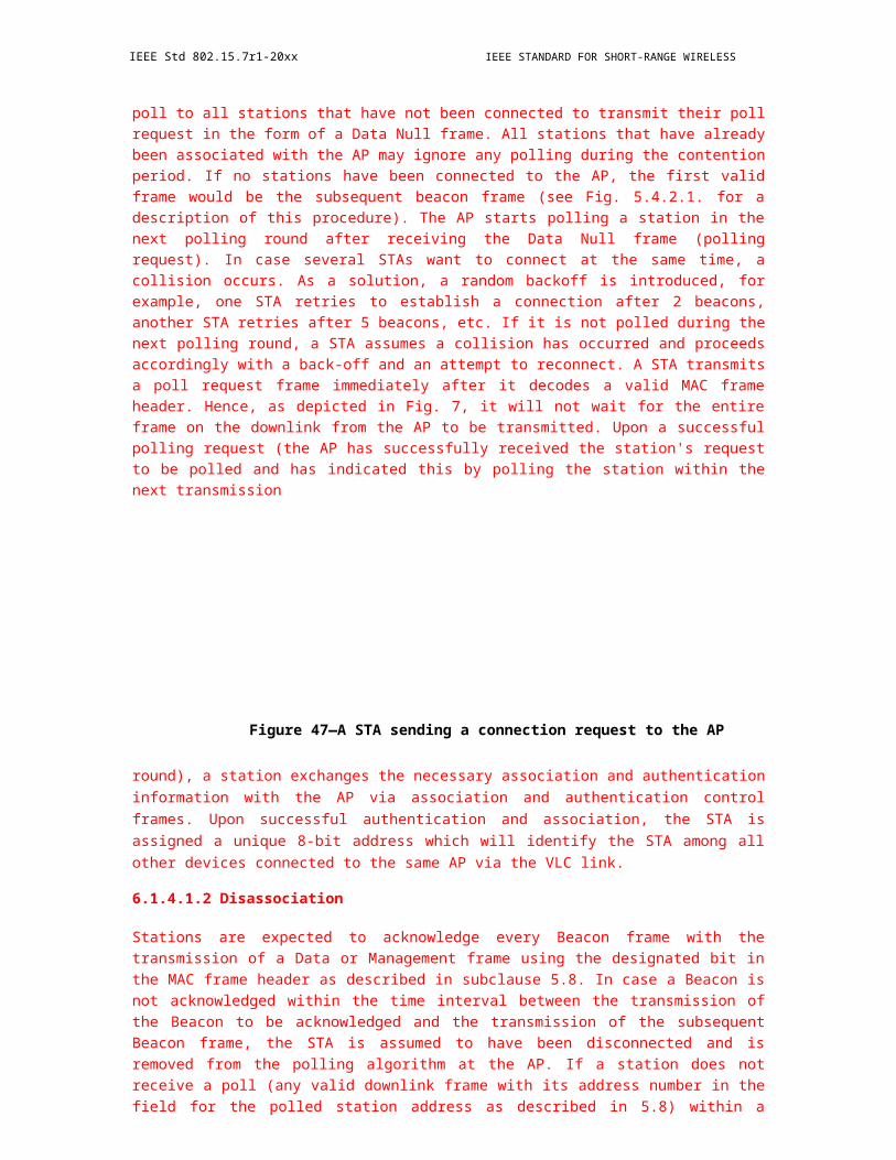
IEEE Std 802.15.7r1-20xx IEEE STANDARD FOR SHORT-RANGE WIRELESS
Figure 84—Extended preamble mode provided by the MAC
The MAC uses the knowledge of the idle time and may increase the number of preamble repetitions during the frame transmission to cover the idle time period. The extended preamble is made continuous to the existing preamble of the next frame transmission. There is a possibility that the idle time may not be an integral multiple of the preamble length. In such cases, it is acceptable to transmit a fraction of the preamble (the latter part) in order to maintain visibility. This fraction of the preamble can be called a truncated preamble.
The MAC can choose to either transmit a idle pattern or an extended preamble in the idle mode during regular operation. The choice is made by the DME and is indicated to the PHY via PLME access to the PHY PIB attribute phyUseExtendedMode (see Table 125).
The fast locking pattern (FLP) part of the preamble sequence (1010... ) shall be used in the extended preamble mode, as shown in Figure 85. Since idle time is not an integral multiple of the preamble, only a fraction of the preamble pattern such as '010' can be sent to complete the idle time.
Figure 85—Truncated preamble in extended preamble mode for utilizing idle time for visibility
NOTE—the dimming requirements shall be met, even during the preambles. The implementer needs to be mindful of
this when doing repetitions of the preamble.7
6.2.14.3 Transmitting visibility pattern during uplink for star topology mode
For the star topology mode, assuming the visibility pattern is sent “in-band” as described in the modulation domain (see 4.4), the point-and-shoot visibility signal from the mobile device cannot be transmitted
7Notes in text, tables, and figures are given for information only and do not contain requirements needed to implement the standard.
124 Copyright © 20xx IEEE. All rights reserved.
OPTICAL COMMUNICATION IEEE Std 802.15.7r1-20xx
continuously since multiple users could be pointing to the infrastructure fixed coordinator. This makes the visibility signal difficult to attain due to the low duty cycle. Hence, the knowledge of idle periods (unused slots) is transmitted by the beacons and the mobile device uses the idle periods for transmitting the visibility pattern to the fixed coordinator. All mobile devices talking to a coordinator can share the empty slots for the CVD frame transmission during uplink.
Figure 86—Usage of CVD frames during star topology operation
6.2.14.4 Dimming override capability
This standard supports bypassing the dimmer functionality during VLC operation. The dimmer control can be set to maximum brightness to facilitate VLC communication. As soon as the VLC communication is completed, the dimmer regains control of the optical source driver and resumes normal operation.
A dimmer override capability request signal is added to the MLME SAP and provided to the external dimmer interface, using the MAC PIB attribute, macDimOverrideRequest, as shown in Table 62. This dimmer override request attribute shall be set to ‘1’ during VLC operation and shall be set to ‘0’ after the communication has been completed. The dimmer circuit can decide whether to accept or reject this request. The response to this dimmer override request signal by the external dimmer circuit is out-of-scope of this standard. The MLME-GET (see 7.3.4) and MLME-SET(see 7.3.10) primitives are used to read and write PIB attributes for dimming.
6.2.14.5 PWM signal override
A PWM signal override request signal is added to the MLME SAP, using the MAC PIB attribute, macDimPWMOverrideRequest, as defined in Table 62 and provided to the external dimmer interface. This PWM override request attribute shall be set to ‘1’ to inform the dimmer circuit that the VLC PHY will be responsible for dimming and to disable any PWM circuit present in the dimmer. The duty cycle for dimming
Copyright © 2011 IEEE. All rights reserved. 125
IEEE Std 802.15.7r1-20xx IEEE STANDARD FOR SHORT-RANGE WIRELESS
is then driven by modulation mode provided by the VLC PHY (such as VPPM). The response to this PWM override request signal by the external dimmer circuit is out-of- scope of this standard. The MLME-GET (see 7.3.4) and MLME-SET (see 7.3.10) primitives are used to read and write PIB attributes for dimming.
6.2.14.6 MAC layer transmission adjustment for dimming
Referring to Figure 87, the infrastructure MAC adjusts the data transmission to match the duty cycle requirements from the dimmer.
Figure 87—MSC for dimming
6.2.14.7 Device discovery and association in the presence of dimming and visibility
The visibility pattern can help with device discovery when the idle pattern or the data has been modified because of the PHY and MAC layer modulation changes to support dimming. Based on the dimming pattern change and duty cycle, the VLC device may choose to associate with a different coordinator that is currently not being dimmed or has a higher duty cycle (more illumination). The visibility pattern is uncoded as shown in Figure 115. The header for the CVD frame is sent at the lowest data rate corresponding to the currently
126 Copyright © 20xx IEEE. All rights reserved.

OPTICAL COMMUNICATION IEEE Std 802.15.7r1-20xx
negotiated clock rate. Figure 88 shows an example of using the visibility pattern as a signal to establish the best connectivity to an infrastructure device.
Figure 88—Example of using the visibility pattern to establish best connectivity to an infrastructure device
6.2.14.8 Link adaptation for dimming support
Dimming requirements of the infrastructure should be notified to VLC RX device, so that the VLC receiver can adapt to the dimming pattern of the data when VPPM is used. The infrastructure coordinator may receive an external dimming request. A dimming adaptation timer is used that delays the time between the dimming request and the actual dimming of the light source. With this knowledge of an incoming dimming, the link between the devices can be adapted to work at a new (lower) data rate (if dimmed) without requiring the link to be interrupted or possible link failure. This dimming adaptation is indicated and supported by the MAC dimming notification command frame in 6.7.10. Figure 89 shows an example of delay dimming and adapt resources for uninterrupted link.
Copyright © 2011 IEEE. All rights reserved. 127
IEEE Std 802.15.7r1-20xx IEEE STANDARD FOR SHORT-RANGE WIRELESS
Figure 89—Usage of MAC layer to delay dimming and adapt resources for uninterrupted link
6.3 Fraunhofer Superframe Structure
6.3.1 Duplex mode
FFS
6.3.2 Superframe
A coordinator on a VPAN can bound its channel time using a superframe structure. The format of the superframe is defined by the coordinator and varies with the network topologies. The superframe is bounded by beacons sent by the coordinator and is divided into equally sized time slots (TS). The duration of the superframe for star and coordinated network topologies shall be fixed and set to Tsuperframe. Each superframe can have two or three portions: beacon period (BP), contention access period (CAP) and optional contention-free period (CFP), as shown in Figure 7-1.
In peer-to-peer and star topology, the BP shall contain only one beacon slot. In coordinated network topology, the BP consists one to a maximal of MaxBeaconSlot beacon slots. The coordinator transmits a beacon in one of the multiple beacon slots every superframe. The structure of a BP is specified in the beacon frame. The duration of each beacon slot is equal to the sum of the duration of a beacon PPDU and the subsequent beacon-to-beacon interframe space. The beacons are used to synchronize the attached devices, to convey the information and parameters of the VPAN operation (e.g., channel access information).
The CAP shall immediately following the BP and complete before the CFP. If the CFP is zero length, the CAP shall complete at the end of the superframe. The CAP shall be at least aMinCAPLength and shall shrink or grow dynamically to accommodate the size of the CFP. Any device wishing to communicate during the CAP competes with other devices via CSMA/CA.
128 Copyright © 20xx IEEE. All rights reserved.

OPTICAL COMMUNICATION IEEE Std 802.15.7r1-20xx
The CFP may be present in star and coordinated network topologies. For low-latency applications or applications requiring specific data bandwidth, the coordinator is allowed to dedicate portions during the CFP to that application. These portions are called guaranteed time slots (GTSs) . The GTSs forms the CFP, which always appears at the end of the superframe starting at a TS boundary immediately following the CAP. More information on the CFP and GTSs is provided in 7.4.1 and 7.6.1. All contention-based transactions shall be completed before the CFP begins. Also each device transmitting in a GTS ensures that its transaction is complete before the time of the next GTS or the end of the CFP.
All transactions are completed by the time of the next beacon.
Figure 90—An example of the superframe structure of different network topologies
Figure 91—An example of the structure of the beacon period
6.4 MAC frame formats
This subclause specifies the format of the MAC frame (MPDU). Each MAC frame consists of the following basic components:
Copyright © 2011 IEEE. All rights reserved. 129
IEEE Std 802.15.7r1-20xx IEEE STANDARD FOR SHORT-RANGE WIRELESS
a) A MHR, which comprises frame control, sequence number, address information, and security-related information.
b) A MSDU, of variable length, which contains information specific to the frame type. Acknowledgment frames do not contain a payload.
c) A MFR, which contains a FCS.
The frames in the MAC sublayer are described as a sequence of fields in a specific order. All frame formats in this subclause are depicted in the order in which they are transmitted by the PHY, from left to right, where the left most bit is transmitted first in time. Bits within each field are numbered from 0 (left most and least significant) to k – 1 (right most and most significant), where the length of the field is k bits. Fields that are longer than a single octet are sent to the PHY in the order from the octet containing the lowest numbered bits to the octet containing the highest numbered bits.
For every MAC frame, all reserved bits shall be ignored upon receipt.
6.4.1 General MAC frame format
The MAC frame format is composed of a MHR, a MSDU, and a MFR. The fields of the MHR appear in a fixed order; however, the addressing fields may not be included in all frames. The general MAC frame shall be formatted as illustrated in Figure 92.
Octets:1 0/2 0/2/8 0/2 0/2/8
0/5/6/10/variable 22 14
Frame Sequence Destina- Destination Source Source Auxiliary Frame FCSControl Number tion VPAN Address VPAN Address Security Payload
Identifier Identifier Header
Addressing fields
MHR MSDU MFR
Figure 92—General MAC frame format
6.4.1.1 Frame control field
The frame control field is 2 octets in length and contains information defining the frame type, addressing fields, and other control flags. The frame control field shall be formatted as illustrated in Figure 93. Reserved bits are set to zero on transmission and ignored on reception.
Bits:2–5 6–8 9 10 11 12–13 14–150–1
Frame Reserved Frame Security Frame Ack Dest SourceVersion Type Enabled Pending Request Addressing Addressing
Mode Mode
Figure 93—Format of the frame control field
130 Copyright © 20xx IEEE. All rights reserved.
OPTICAL COMMUNICATION IEEE Std 802.15.7r1-20xx
6.4.1.1.1 Frame Version subfield
The Frame Version subfield specifies the version number corresponding to the frame. This subfield shall be set to 0b00 to indicate a frame compatible with IEEE Std 802.15.7. All other subfield values shall be reserved for future use.
6.4.1.1.2 Frame type subfield
The Frame Type subfield shall be set to one of the nonreserved values listed in Table 8.
Table 8—Values of the Frame Type subfield
Frame type value
Descriptionb2 b1 b0
000 Beacon
001 Data
010 Acknowledgment
011 Command
100 CVD
101–111 Reserved
6.4.1.1.3 Security Enabled subfield
The Security Enabled subfield is 1 bit in length, and it shall be set to one if the frame is protected by the MAC sublayer and shall be set to zero otherwise. The Auxiliary Security Header field of the MHR shall be present only if the Security Enabled subfield is set to one.
6.4.1.1.4 Frame Pending subfield
The Frame Pending subfield is 1 bit in length and shall be set to one if the device sending the frame has more data for the recipient. This subfield shall be set to zero otherwise (see 6.2.7.3).
The Frame Pending subfield shall be used only in beacon frames or frames transmitted either during the CAP by devices operating on a beacon-enabled VPAN or at any time by devices operating on a nonbeacon-enabled VPAN.
At all other times, it shall be set to zero on transmission and ignored on reception.
6.4.1.1.5 Acknowledgment Request subfield
The Acknowledgment Request subfield is 1 bit in length and specifies whether an acknowledgment is required from the recipient device on receipt of a data or MAC command frame. If this subfield is set to one, the recipient device shall send an acknowledgment frame only if, upon reception, the frame passes the third level of filtering as shown in 6.2.7.2. If this subfield is set to zero, the recipient device shall not send an acknowledgment frame.
Copyright © 2011 IEEE. All rights reserved. 131
IEEE Std 802.15.7r1-20xx IEEE STANDARD FOR SHORT-RANGE WIRELESS
6.4.1.1.6 Destination Addressing Mode subfield
The Destination Addressing Mode subfield shall be set to one of the nonreserved values listed in Table 9.
If this subfield is equal to zero and the Frame Type subfield does not specify that this frame is an acknowledgment or beacon frame, the Source Addressing Mode subfield shall be nonzero, implying that the frame is directed to the VLC coordinator with the VPAN identifier as specified in the Source VPAN Identifier field. If this subfield is equal to 01, the Source Addressing Mode subfield shall be equal to 01, implying that the frame is a broadcast frame, and no source or destination address fields are present in the frame.
Table 9—Possible values of the Destination Addressing Mode andSource Addressing Mode subfields
Addressing mode value
Descriptionb1 b0
00 VPAN identifier and address fields are not present.
01 No address field (broadcast only mode with no addressfields present). Addresses with all ones of 16 bits or 64 bitsare defined as broadcast.
10 Address field contains a 16-bit short address.
11 Address field contains a 64-bit extended address.
6.4.1.1.7 Source Addressing Mode subfield
The Source Addressing Mode subfield shall be set to one of the nonreserved values listed in Table 9.
If this subfield is equal to zero and the Frame Type subfield does not specify that this frame is an acknowledgment frame, the Destination Addressing Mode subfield shall be nonzero, implying that the frame has originated from the coordinator with the VPAN identifier as specified in the Destination VPAN Identifier field.
If this subfield is equal to 01, the Source Addressing Mode subfield shall be equal to 01, implying that the frame is a broadcast frame, and no source or destination address fields are present in the frame.
6.4.1.2 Sequence Number field
The Sequence Number field is 1 octet in length and specifies the sequence identifier for the frame.
For a beacon frame, the Sequence Number field shall specify a BSN. For a data, acknowledgment, or MAC command frame, the Sequence Number field shall specify a DSN that is used to match an acknowledgment frame to the data or MAC command frame.
6.4.1.3 Destination VPAN Identifier field
The Destination VPAN Identifier field, when present, is 2 octets in length and specifies the unique VPAN identifier of the intended recipient of the frame. A value of 0xffff in this field shall represent the broadcast VPAN identifier, which shall be accepted as a valid VPAN identifier by all devices currently listening to the channel.
132 Copyright © 20xx IEEE. All rights reserved.

OPTICAL COMMUNICATION IEEE Std 802.15.7r1-20xx
This field shall be included in the MAC frame only if the Destination Addressing Mode subfield of the frame control field is 10 or 11.
6.4.1.4 Destination Address field
The Destination Address field, when present, is either 2 octets or 8 octets in length, according to the value specified in the Destination Addressing Mode subfield of the frame control field, see 6.4.1.1.6, and specifies the address of the intended recipient of the frame. A 16-bit value of 0xffff in this field shall represent the broadcast short address, which shall be accepted as a valid 16-bit short address by all devices currently listening to the channel.
This field shall be included in the MAC frame only if the Destination Addressing Mode subfield of the frame control field is nonzero.
6.4.1.5 Source VPAN Identifier field
The Source VPAN Identifier field, when present, is 2 octets in length and specifies the unique VPAN identifier of the originator of the frame. This field shall be included in the MAC frame only if the Source Addressing Mode and VPAN ID Compression subfields of the frame control field are nonzero and equal to zero, respectively.
The VPAN identifier of a device is initially determined during association on a VPAN, but may change following a VPAN identifier conflict resolution as discussed in 6.2.3.
6.4.1.6 Source Address field
The Source Address field, when present, is either 2 octets or 8 octets in length, according to the value specified in the Source Addressing Mode subfield of the frame control field, as shown in 6.4.1.1.7, and specifies the address of the originator of the frame. This field shall be included in the MAC frame only if the Source Addressing Mode subfield of the frame control field is 10 or 11.
6.4.1.7 Auxiliary Security Header field
The Auxiliary Security Header field has a variable length and specifies information required for security processing, including how the frame is actually protected (security level) and which keying material from the MAC security PIB is used (see 8.5.1). This field shall be present only if the Security Enabled subfield is set to one. For details on formatting, see 8.4.
6.4.1.8 Frame Payload field
The Frame Payload field has a variable length and contains information specific to individual frame types. If the Security Enabled subfield is set to one in the frame control field, the frame payload is protected as defined by the security suite selected for that frame.
6.4.1.9 FCS field
The FCS field is 2 octets in length and is explained in Annex C. The FCS is calculated over the MHR and MSDU parts of the frame. The FCS shall be only generated for payloads greater than zero bytes.
6.4.2 UFSOOK MAC Frame Format
The native MPDU has too much overhead for UFSOOK OCC and most of the fields are not needed for a short, repetitive MSDU. The alternative MAC frame format for USFOOK uses only the MSDU (frame pay-load) and the MFR (FCS) (Figure 92). The MHR is not used.
Copyright © 2011 IEEE. All rights reserved. 133
IEEE Std 802.15.7r1-20xx IEEE STANDARD FOR SHORT-RANGE WIRELESS
The FCS fields is optional for UFSOOK and is currently CRC-3.
6.4.2.1 UFSOOK MIMO Protocol
UFSOOK ultilizes a MIMO protocol so the receiver can figure out which LED lights, amongst multiple LED lights, are transmitting data. The protocol supports spatial redundancy, spatial multiplexing and a com-bination of both.
6.4.2.1.1 Additional delimiter definitions
In addition to the previously defined start frame delimiter, a data delimiter is also defined. The two delimit-ers can be used to construct a MIMO frame that supports multiple MIMO modes.
Figure 94—Additional MIMO delimiter definitions
6.4.2.1.2 Protocol Flowchart
A flowchart showing how the data delimiters are utilized to form a protocol is shown in the following figure.
134 Copyright © 20xx IEEE. All rights reserved.
OPTICAL COMMUNICATION IEEE Std 802.15.7r1-20xx
Figure 95—UFSOOK MIMO Protocol
6.4.3 Twinkle VPPM MAC Frame Format
The native MPDU has too much overhead for twinkle VPPM OCC and most of the fields are not needed. The alternative MAC frame format for twinkle VPPM uses only the source address filed of the MHR, the MSDU (frame payload) and the MFR (FCS) (Figure 92). The other sub-fields of the MHR is not used.
6.4.4 RS-FSK MAC Frame Format
This sub-clause specifies the format of the RS-FSK MAC frame (MPDU). Each MAC frame consists of the following basic components:
A MFH, which comprises frame control, sequence number and address information.
A MFDU, of variable length, which contains information specific to the frame type. Acknowledge-ment frames do not contain a payload.
A MFT, which contains a FCS.
Copyright © 2011 IEEE. All rights reserved. 135
IEEE Std 802.15.7r1-20xx IEEE STANDARD FOR SHORT-RANGE WIRELESS
The frames in the MAC sub-layer are described as a sequence of fields in a specific order. All frame formats in this sub-clause are depicted in the order in which they are transmitted by the PHY, from left to right, where the left most bit is transmitted first in time. Bits within each field are numbered from 0 (left most and least significant) to k-1 (right most and most significant), where the length of the field is k bits. Fields that are longer than a single octet are sent to the PHY in the order form the octet containing the lowest numbered bits to the octet containing the highest numbered bits.
For every MAC frame, all reserved bits shall be ignored upon receipt.
6.4.4.1 General MAC frame format
The MAC frame format Figure 96 is composed of a MAC frame header (MFH), a MAC frame data unint (MFDU), and a MAC frame tail (MFT). The fields of the MFH appear in a fixed order; however, the addressing fields may not be included in all frames. The general MAC frame shall be formatted as illustrated in Figure Y.
Figure 96—RS-FSK general MAC frame format
6.4.4.2 Frame Control field
The Frame Control field is 1 octet in length and contains information defining the frame type, addressing fields, and other control flags. The frame control field shall be formatted as illustrated in Figure 97. Reserved bits are set to zero on transmission and ignored on reception.
Figure 97—Format of the frame control field
136 Copyright © 20xx IEEE. All rights reserved.

OPTICAL COMMUNICATION IEEE Std 802.15.7r1-20xx
6.4.4.3 Frame Type subfield
The Frame Type subfield shall be set to one of the non-reserved values listed in Table 10.
Table 10—Values of the frame type subfield
Frame Type ValueDescriptionb2 b1 b0
000 Reserved
001 Data
010 Command
011 Security Configuring Mode
100-111 Reserved
6.4.4.3.1 Security Enabled subfield
The Security Enabled subfield is 1 bit in length, and it shall be set to one if the frame is protected by the MAC sublayer and shall be set to zero otherwise. Prior to enable this field, the transmitter should configure the receiver into Security Enabled prepared state through the Frame Type subfield.
6.4.4.3.2 Frame Pending subfield
The Frame Pending subfield is 1 bit in length and shall be set to one if the device sending the frame has more data for the recipients. This subfield shall be set to zero otherwise.
The Frame Pending subfield shall be used only during the DF, at SF it shall be set to zero on transmission and ignored on reception.
6.4.4.3.3 Destination Addressing Mode subfield
If this subfield is equal to zero, the Destination PAN Address shall not be included.
6.4.4.3.4 Source Addressing Mode subfield
If this subfield is equal to zero, the Source PAN Address shall not be included.
6.4.4.3.5 Sequence Number field
The Sequence Number field is 1 octet in length and specifies the sequence identifier for the frame.
6.4.4.3.6 Destination PAN Address field
The Destination PAN Address, when present, is 2 octets in length, and specifies the address of the intended recipient of the frame. A 16-bit value of 0xFFFF in this field shall represent the broadcast address, which shall be accepted as a valid 16-bit address by all devices currently listening to the channel.
This field shall be included in the MAC frame only if the Destination Addressing Mode subfield of the frame control field is nonzero.
Copyright © 2011 IEEE. All rights reserved. 137
IEEE Std 802.15.7r1-20xx IEEE STANDARD FOR SHORT-RANGE WIRELESS
6.4.4.3.7 Source PAN Address field
The Source PAN Address, when present, is 2 octets in length, and specifies the address of the originator of the frame. This field shall be included in the MAC frame only if the Source Addressing Mode subfield of the frame control field is nonzero.
6.4.4.4 MFDU
The MFDU contains the frame payload, which has a variable length and contains information specific to individual frame types. If the frame control is configured to Security Enabled previously, then the frame payload is protected as defined by the security suite selected at that time.
6.4.4.5 MFT
Currently MFT contains only the frame checksum (FCS). The FCS field is 2 octets in length and is explained in somewhere else in the document. The FCS is calculated over the MFH and MSDU part of the frame. The FCS shall be only generated for payloads greater than zero bytes.
6.4.5 VTASC MAC Frame Formats
The MAC frame structure presented in IEEE802.15.7-2011 (Figure 44 - General MAC Frame Format) is shown in Figure 7-1.
Figure 98—General MAC Frame Format
The IEEE802.15.7r1 MAC frame structure is formatted as illustrated in Figure 7-2 for proposed 2 Dimen-sional codes.
138 Copyright © 20xx IEEE. All rights reserved.
OPTICAL COMMUNICATION IEEE Std 802.15.7r1-20xx
Figure 99—IEEE802.15.7r1 MAC Frame Format
Frame Control Field:
The frame control field presented in IEEE802.15.7-2011 (Figure 45 - Format of the Frame Control Field) is shown in Figure 7-3.
Figure 100—IEEE802.15.7 Frame Control Field Format
The IEEE802.15.7r1 frame control field is formatted as illustrated in Figure 7-4 for proposed 2 Dimensional codes.
Copyright © 2011 IEEE. All rights reserved. 139

IEEE Std 802.15.7r1-20xx IEEE STANDARD FOR SHORT-RANGE WIRELESS
Frame Version Subfield: Specifies the version number corresponding to the frame. This subfield shall be set to 0b01 to indicate a frame compatible with IEEE Standard 802.15.7r1. And all other subfield values shall be reserved for future use.
Frame Type Subfield: Specifies the Frame Type used in MAC Frame. This field shall be set to one of the non-reserved values listed in Table 7-1.
Figure 101—IEEE802.15.7r1 Frame Type Subfield
Security Enabled Subfield: Species the Security on Data Frame is enable or not on transmission. This field is 1 bit in length, and it shall be set to one if the frame is protected by the MAC sublayer and shall be set to zero otherwise. The Auxiliary Security Header field of the MHR shall be present only if the Security Enabled subfield is set to one.
Frame Pending Subfield: Species the Pending on Data Frame is available or not on transmission. This field is 1 bit in length and shall be set to one if the device sending the frame has more data for the recipient. This subfield shall be set to zero otherwise.
140 Copyright © 20xx IEEE. All rights reserved.
OPTICAL COMMUNICATION IEEE Std 802.15.7r1-20xx
Acknowledgment Request Subfield: Specifies whether an acknowledgment is required from the recipient device on receipt of a data or MAC command frame. This field is 1 bit in length and this subfield is set to one, the recipient device shall send an acknowledgment frame. If this subfield is set to zero, the recipient device shall not send an acknowledgment frame.
Sequence Number Field:
The Sequence Number field is 1 octet in length and specifies the sequence identifier for the frame.
For a beacon frame, the Sequence Number field shall specify a BSN. For a data, acknowledgment, or MAC command frame, the Sequence Number field shall specify a DSN that is used to match an acknowledgment frame to the data or MAC command frame.
Destination Address Field:
The Destination Address field, when present, is either 2 octets or 8 octets in length, according to the value specified in the Destination Addressing Mode subfield of the frame control field, and specifies the address of the intended recipient of the frame.
A 16-bit value of 0xffff in this field shall represent the broadcast short address, which shall be accepted as a valid 16-bit short address by all devices currently listening to the channel.
This field shall be included in the MAC frame only if the Destination Addressing Mode subfield of the frame control field is nonzero.
Source Address Field:
The Source Address field, when present, is either 2 octets or 8 octets in length, according to the value spec-ified in the Source Addressing Mode subfield of the frame control field, , and specifies the address of the originator of the frame.
This field shall be included in the MAC frame only if the Source Addressing Mode subfield of the frame control field is 10 or 11.
Frame Payload Field:
The Frame Payload field has a variable length and contains information specific to individual frame types. If the Security Enabled subfield is set to one in the frame control field, the frame payload is protected as defined by the security suite selected for that frame.
FCS Field:
The FCS field is 2 octets in length and the FCS is calculated over the MHR and MSDU parts of the frame. The FCS shall be only generated for payloads greater than zero bytes.
The FCS is option is given as an optional option, it is adaptive to RS/CRC/NONE. ?
6.4.6 Format of individual frame types
Five frame types are defined: beacon, data, acknowledgment, command, and CVD. These frame types are discussed in 6.4.6.1 through 6.4.6.4.3.
Copyright © 2011 IEEE. All rights reserved. 141

IEEE Std 802.15.7r1-20xx IEEE STANDARD FOR SHORT-RANGE WIRELESS
6.4.6.1 Beacon frame format
The beacon frame shall be formatted as illustrated in Figure 102.
Octets: 2 1 4/10 0/5/6/10/14 2 variable variable 0/1 variable 2
Frame Sequence Addressing Auxiliary Superframe GTS Pending cellSearch Beacon FCSControl Number fields Security Spec fields address Length Payload
Header (Figure 10 fields3) (Figure 10
4)
MHR MSDU MFR
Octets:2 1 4/10 0/5/6/10/14 3 0/1 variable Variable Variable 0/1 Variable 2Frame Control
Sequence Number
Addressing fields
Auxiliary Security Header
Superframe Spec
BP Descriptor
CAP Descriptor
GTS fields
(Figure 103)
Pending address fields
(Figure 104)
cellSearchLength
Beacon Payload
FCS
MHR MSDU MFR
Figure 102—Beacon frame format
The GTS fields shall be formatted as illustrated in Figure 103, and the pending address fields shall be formatted as illustrated in Figure 104.
Octets: 1 0/1 variable
GTS Specification GTS Directions GTS List
Figure 103—Format of the GTS information fields
Octets: 1 variable
Pending Address Specification Address List
Figure 104—Format of the pending address information fields
The order of the fields of the beacon frame shall conform to the order of the general MAC frame as illustrated in Figure 92.
6.4.6.1.1 Beacon frame MHR fields
The MHR for a beacon frame shall contain the frame control field, the Sequence Number field, the Source VPAN Identifier field, and the Source Address field.
In the frame control field, the Frame Type subfield shall contain the value that indicates a beacon frame, as shown in Table 8, and the Source Addressing Mode subfield shall be set as appropriate for the address of the coordinator transmitting the beacon frame. If protection is used for the beacon, the Security Enabled subfield shall be set to one. If a broadcast data or command frame is pending, the frame pending subfield shall be set to one. All other subfields shall be set to zero by the sender and ignored on reception.
The Sequence Number field shall contain the current value of macBSN.
142 Copyright © 20xx IEEE. All rights reserved.
OPTICAL COMMUNICATION IEEE Std 802.15.7r1-20xx
The addressing fields shall comprise only the source address fields. The Source VPAN Identifier and Source Address fields shall contain the VPAN identifier and address, respectively, of the device transmitting the beacon.
The Auxiliary Security Header field, if present, shall contain the information required for security processing of the beacon frame, as specified in 6.4.1.7.
6.4.6.1.2 Superframe Specification field
The Superframe Specification field shall be formatted as illustrated in Figure 105.
Bits: 0–3 4-7 8-11 12 13 14 15
Beacon Superframe Final Reserved VPAN Association cellSearchEnOrder Order CAP Slot Coordinator Permit
Bits: 0–3 4-78-10
11-14 15 16 17 1819-22
Beacon Superframe VPAN mode FinalCAP Slot
Beacon type VPAN Association cellSearchEn Count down Reserved
Order Order Coordinator Permit
Figure 105—Format of the Superframe Specification field
The Beacon Order subfield shall specify the transmission interval of the beacon. Refer to 6.2.1.1 for an explanation of the relationship between the beacon order and the beacon interval.
The Superframe Order subfield shall specify the length of time during which the superframe is active (i.e., receiver enabled), including the beacon frame transmission time. Refer to 6.2.1.1 for an explanation of the relationship between the superframe order and the superframe duration.
The Final CAP Slot subfield specifies the final superframe slot utilized by the CAP. The duration of the CAP, as implied by this subfield, shall be greater than or equal to the value specified by aMinCAPLength. However, an exception is allowed for the accommodation of the temporary increase in the beacon frame length needed to perform GTS maintenance, as in 6.4.6.1.3.
The Beacon Type subfield shall be set to one if the beacon frame is a normal beacon which is transmitted in the beacon period regularly, and set to zero if the beacon frame is an additional beacon which is transmitted in a GTS in the CFP period.
The VPAN Coordinator subfield shall be set to one if the beacon frame is being transmitted by the coordinator. Otherwise, the VPAN Coordinator subfield shall be set to zero.
The Association Permit subfield shall be set to one if macAssociationPermit is set to TRUE (i.e., the coordinator is accepting association to the VPAN). The association permit bit shall be set to zero if the coordinator is currently not accepting association requests on its network.
If the cellSearchEn bit is set, the cellSearchLength is transmitted as an additional field in the beacon frame, as shown in Figure 102.
6.4.6.1.x BP Descriptor field
The BP Descriptor field only exists when the VPAN Mode sub-field in Superframe Specification field is set to 10, i.e., the coordinated mode.
The BP Descriptor field shall be formatted as illustrated in Figure xx.
Bits: 0-3 4-7Beacon Slot Number Beacon Slot Used
Figure xx - BP descriptor field
The Beacon Slot Number subfield shall contain the number of the beacon slots in the BP.
The Beacon Slot Used subfield shall indicates which beacon slot is used by this VPAN.
6.4.6.1.y CAP Descriptor field
[editor’s note: the text will be privoded as a comment against D1]
6.4.6.1.3 GTS Specification field
The GTS Specification field shall be formatted as illustrated in Figure 106.
Bits: 0–2 3–6 7
GTS Descriptor Count Reserved GTS Permit
Figure 106—Format of the GTS Specification field
Copyright © 2011 IEEE. All rights reserved. 143

IEEE Std 802.15.7r1-20xx IEEE STANDARD FOR SHORT-RANGE WIRELESS
The GTS Descriptor Count subfield specifies the number of 3-octet GTS descriptors contained in the GTS List field of the beacon frame. If the value of this subfield is greater than zero, the size of the CAP shall be allowed to dip below aMinCAPLength to accommodate the temporary increase in the beacon frame length caused by the inclusion of the subfield. If the value of this subfield is zero, the GTS Directions field and GTS List field of the beacon frame are not present.
The GTS Permit subfield shall be set to one if macGTSPermit is equal to TRUE (i.e., the coordinator is accepting GTS requests). Otherwise, the GTS Permit field shall be set to zero.
6.4.6.1.4 GTS Directions field
The GTS Directions field shall be formatted as illustrated in Figure 107.
Bits: 0–6 7
GTS Directions Mask Reserved
Figure 107—Format of the GTS Directions field
The GTS Directions Mask subfield contains a mask identifying the directions of the GTSs in the superframe. The lowest bit in the mask corresponds to the direction of the first GTS contained in the GTS List field of the beacon frame, with the remainder appearing in the order that they appear in the list. Each bit shall be set to one if the GTS is a receive-only GTS or to zero if the GTS is a transmit-only GTS. GTS direction is defined relative to the direction of the data frame transmission by the device.
6.4.6.1.5 GTS List field
The size of the GTS List field is defined by the values specified in the GTS Specification field of the beacon frame and contains the list of GTS descriptors that represents the GTSs that are being maintained. The maximum number of GTS descriptors shall be limited to seven.
Each GTS descriptor shall be formatted as illustrated in Figure 108.
Bits: 0–15 16–19 20–23
Device Short Address GTS Starting Slot GTS Length
Figure 108—Format of the GTS descriptor
The Device Short Address subfield shall contain the short address of the device for which the GTS descriptor is intended.
The GTS Starting Slot subfield contains the superframe slot at which the GTS is to begin.
The GTS Length subfield contains the number of contiguous superframe slots over which the GTS is active.
6.4.6.1.6 Pending Address Specification field
The Pending Address Specification field shall be formatted as illustrated in Figure 109.
144 Copyright © 20xx IEEE. All rights reserved.
OPTICAL COMMUNICATION IEEE Std 802.15.7r1-20xx
Bits: 0–2 3 4–6 7
Number of Short Reserved Number of Extended ReservedAddresses Pending Addresses Pending
Figure 109—Format of the Pending Address Specification field
The Number of Short Addresses Pending subfield indicates the number of 16-bit short addresses contained in the Address List field of the beacon frame.
The Number of Extended Addresses Pending subfield indicates the number of 64-bit extended addresses contained in the Address List field of the beacon frame.
6.4.6.1.7 Address List field
The size of the Address List field is determined by the values specified in the Pending Address Specification field of the beacon frame and contains the list of addresses of the devices that currently have messages pending with the coordinator. The address list shall not contain the broadcast short address 0xffff.
The maximum number of addresses pending shall be limited to seven and may comprise both short and extended addresses. All pending short addresses shall appear first in the list followed by any extended addresses. If the coordinator is able to store more than seven transactions, it shall indicate them in its beacon on a first-come-first-served basis, ensuring that the beacon frame contains at most seven addresses.
6.4.6.1.8 Beacon Payload field
The Beacon Payload field is an optional sequence of up to aMaxBeaconPayloadLength octets specified to be transmitted in the beacon frame by the next higher layer. The set of octets contained in macBeaconPayload shall be copied into this field.
6.4.6.2 Data frame format
The data frame shall be formatted as illustrated in Figure 110.
Octets: 2 1(As defined in
0/5/6/10/14 variable 26.4.6.2.1)
frame control Sequence Addressing Auxiliary Data Payload FCSNumber fields Security Header
MHR MSDU MFR
Figure 110—Data frame format
The order of the fields of the data frame shall conform to the order of the general MAC frame as illustrated in Figure 92.
6.4.6.2.1 Data frame MHR fields
The MHR for a data frame shall contain the frame control field, the Sequence Number field, the destination VPAN identifier/address fields, and/or the source VPAN identifier/address fields.
Copyright © 2011 IEEE. All rights reserved. 145
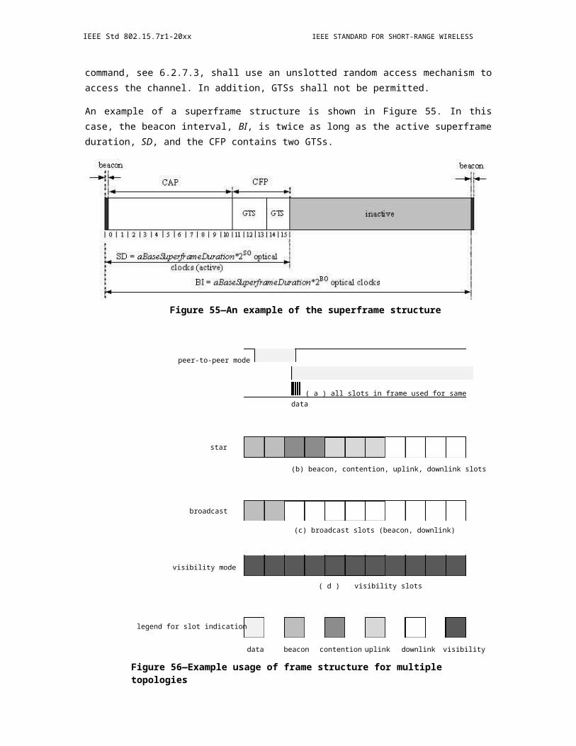
IEEE Std 802.15.7r1-20xx IEEE STANDARD FOR SHORT-RANGE WIRELESS
In the frame control field, the Frame Type subfield shall contain the value that indicates a data frame, as shown in Table 8. If protection is used for the data, the Security Enabled subfield shall be set to one. All other subfields shall be set appropriately according to the intended use of the data frame. All reserved subfields shall be set to zero by the sender and ignored on reception.
The Sequence Number field shall contain the current value of macDSN.
The addressing fields shall comprise the destination address fields and/or the source address fields, dependent on the settings in the frame control field.
The Auxiliary Security Header field, if present, shall contain the information required for security processing of the data frame, as specified in 6.4.1.7.
6.4.6.2.2 Data Payload field
The payload of a data frame shall contain the sequence of octets that the next higher layer has requested the MAC sublayer to transmit. The data type field is 1 byte and is explained in Table 11.
Table 11—Data Payload field
Bits 0–1 Bits 2–7 variable
00—Single Number of PPDUs per data frame Data payload01—Packed10—Burst
11—Reserved
The data type field mentions the format used for sending the data—single, packed, or burst. It also mentions the number of PPDUs that are associated for this data frame.
The payload of a data frame shall contain the sequence of octets that the next higher layer has requested the MAC sub layer to transmit.
6.4.6.3 Acknowledgment frame format
The acknowledgment frame shall be formatted as illustrated in Figure 111.
Octets: 2 1 variable 2
frame control sequence number B-ACK frame payload FCS(optional)
MHR MSDU MFR
Figure 111—Acknowledgment frame format
The order of the fields of the acknowledgment frame shall conform to the order of the general MAC frame as illustrated in Figure 92. The sequence number is defined in 6.4.6.1.1.
146 Copyright © 20xx IEEE. All rights reserved.

OPTICAL COMMUNICATION IEEE Std 802.15.7r1-20xx
In B-ACK frames, the DestAddr field is set to the SrcAddr of the frame that requested the B- ACK. The B-ACK frame acknowledges correct or incorrect receipt of the previous sequence of frames and provides information for the transmission of the next sequence of frames as described in 6.4.6.3. The B-ACK frame payload is defined in Figure 112.
Octets: 2 1 1 2 0 – n
buffer size frame count reserved sequence control frame bitmap
Figure 112—B-ACK frame payload
The Buffer Size field specifies the maximum number of octets in the sum of the frame payloads of all frames in the next B-ACK sequence. The Frame Count field specifies the maximum number of frames in the next B-ACK sequence. The Sequence Control and frame bitmap fields together specify an acknowledgment window of MSDU fragments and their reception status. The Sequence Control field specifies the Sequence Number and Fragment Number that start the acknowledgment window.
Bits: b15–b14 b13–b3 b2–b0
reserved sequence number fragment number
Figure 113—B-ACK frame bitmap
The frame bitmap field varies in length. A zero-length frame bitmap field indicates an acknowledgment window of length zero. Otherwise, the least-significant octet of the frame bitmap field corresponds to the MSDU indicated by the Sequence Control field, and each bit of the octet corresponds to a fragment of that MSDU. The least-significant bit in each octet corresponds to the first fragment and successive bits correspond to successive fragments. Successive octets present in the frame bitmap field correspond to successive MSDUs, and each bit corresponds to a fragment of the MSDU. The acknowledgment window ends at fragment seven of the MSDU that corresponds to the most-significant octet in the frame bitmap. For all bits within the frame bitmap, a value of ONE indicates that the corresponding fragment was received in either the current sequence or an earlier one. A value of ZERO indicates that the corresponding fragment was not received in the current sequence (although it may have been received in an earlier one). Bits of the least-significant octet of the frame bitmap field corresponding to fragments prior to the start of the acknowledgment window are undefined. Frames with a Sequence Number earlier than the Sequence Number indicated in the Sequence Control field were not received in the last B-ACK sequence. Such frames were previously received or are no longer expected.
The block ACK is applicable to the packed data type. The bitmap and sequence number is repeated for every frame in the burst mode (multiple frames)
The order of the fields of the acknowledgment frame shall conform to the order of the general MAC frame as illustrated.
The MHR for an acknowledgment frame shall contain only the frame control field and the Sequence Number field.
In the frame control field, the Frame Type subfield shall contain the value that indicates an acknowledgment frame, as shown in Table 8. If the acknowledgment frame is being sent in response to a received data request
Copyright © 2011 IEEE. All rights reserved. 147
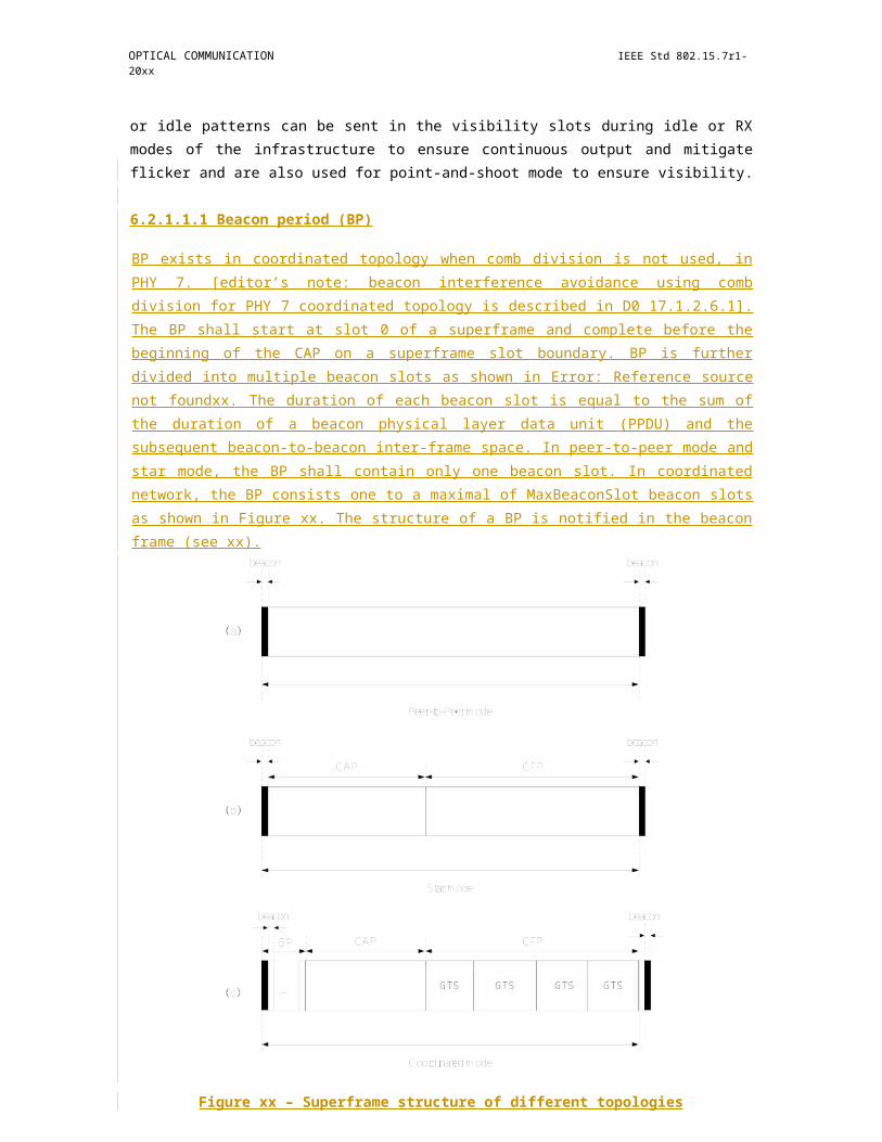
IEEE Std 802.15.7r1-20xx IEEE STANDARD FOR SHORT-RANGE WIRELESS
command, the device sending the acknowledgment frame shall determine whether it has data pending for the recipient. If the device can determine this before sending the acknowledgment frame (see 6.2.7.4.2), it shall set the frame pending subfield according to whether there is pending data. Otherwise, the frame pending subfield shall be set to one. If the acknowledgment frame is being sent in response to either a data frame or another type of MAC command frame, the device shall set the frame pending subfield to zero. All other subfields, except the security enabled subfield, shall be set to zero by the sender and ignored on reception.
The Sequence Number field shall contain the value of the sequence number received in the frame for which the acknowledgment is to be sent.
6.4.6.4 Command frame format
The command frame shall be formatted as illustrated in Figure 114.
Octets: 2 1(As defined in
0/5/6/10/14 1 variable 26.4.6.4.1)
Frame Sequence Addressing Auxiliary Command Command FCSControl Number fields Security Frame Payload
Header Identifier
MHR MSDU MFR
Figure 114—Command frame format
The order of the fields of the MAC command frame shall conform to the order of the general MAC frame as illustrated in Figure 92.
6.4.6.4.1 MAC command frame MHR fields
The MHR for a MAC command frame shall contain the frame control field, the Sequence Number field, the destination VPAN identifier/address fields and/or the source VPAN identifier/address fields.
In the frame control field, the Frame Type subfield shall contain the value that indicates a MAC command frame, as shown in Table 8. If the frame is to be secured, the Security Enabled subfield of the frame control field shall be set to one and the frame secured according to the process described in 8.5.4. Otherwise the Security Enabled subfield of the frame control field shall be set to zero. All other subfields shall be set appropriately according to the intended use of the MAC command frame. All reserved subfields shall be set to zero by the sender and ignored on reception.
The Sequence Number field shall contain the current value of macDSN.
The addressing fields shall comprise the destination address fields and/or the source address fields, dependent on the settings in the frame control field.
The Auxiliary Security Header field, if present, shall contain the information required for security processing of the MAC command frame, as specified in 6.4.1.7.
6.4.6.4.2 Command Frame Identifier field
The Command Frame Identifier field identifies the MAC command being used. This field shall be set to one of the nonreserved values listed in Table 12.
148 Copyright © 20xx IEEE. All rights reserved.
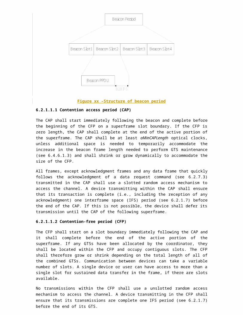
OPTICAL COMMUNICATION IEEE Std 802.15.7r1-20xx
6.4.6.4.3 Command Payload field
The Command Payload field contains the MAC command itself. The formats of the individual commands are described in 6.7.
6.4.6.5 CVD frame format
Octets: 2 Octet: 2 variable
Frame control FCS Visibility pattern
MHR MFR
Figure 115—CVD frame
The structure of the CVD frame is as shown in Figure 115. The CVD frame is used to visually provide information on the communication status, such as misalignment between the two devices, transmission direction, or sending data status; the data transmission quality; and the transferred file size and remaining file size. The visibility pattern has no error protection. The length of the visibility pattern shall be set in the PHY header and the FCS shall not include the visibility pattern of the CVD frame. The FCS is only calculated over the frame control field (MHR) using the cyclic redundancy check (CRC) described in Annex C. The visibility pattern will be generated based on the dimming level requirements and is described in 9.5.1.2. The CVD frame is used by the infrastructure to maintain visibility at all times and by the mobile device for point-and-shoot. The CVD frame can also be used for color stabilization for PHY III as explained in 9.5.4. It should be noted that the CVD frame is not used for communicating the dimming level; rather, the dimming notification command is used for this function as described in 6.7.10.
The CVD frame is sent at the currently negotiated optical clock.
6.5 Fraunhofer MAC frame formats (16/356r0)
6.5.1 Peer-to-Peer
FFS
6.5.2 Star
6.5.2.1 Channel access
Both contention access and contention- free access shall be supported. Contention- free access shall be used for transmissions of beacon frames and transmissions in GFP. Contention access is based on random access and shall be used for transmissions in CAP. Both data and command frames (e.g., association related com-mand frames) can be transmitted in the CAP.
6.5.2.1.1 Channel access in CAP
CSMA/CA mechanism is used during the channel access in CAP, which supports prioritized access. To reduce the probability of collisions among contending devices, a random back-off algorithm is used to sepa-rate the timing that the different devices attempt to transmit. Prioritized access is achieved by assigning dif-ferentiated contention parameters to different access priorities, which allows frames associated with higher access priorities to win the contention with higher probabilities.
Copyright © 2011 IEEE. All rights reserved. 149

IEEE Std 802.15.7r1-20xx IEEE STANDARD FOR SHORT-RANGE WIRELESS
In order to handle the hidden node problems, RTS/CTS mechanism may be used during the CAP. The coor-dinator shall decide and indicate in the beacon if the RTS/CTS protocol can be used in the CAP. The deci-sion on whether the RTS/CTS protocol should be used is out of the scope of this standard.
6.5.2.1.2 Channel access in CFP
The coordinator can divide the CFP of a superframe into multiple GTSs and assign them to itself or the asso-ciated devices which have traffic requiring guaranteed QoS. A device can request GTS allocations through flow establishment procedure, which is controlled by the coordinator and specified in clause 5.4.5.
The coordinator shall distribute the GTS allocations to devices via the beacon frame. The GTS descriptor shall include the basic parameters and information, such as the length and position of the GTS and the device assigned to the GTS. The GTS descriptor may supply additional information, such as the subcarriers/ frequencies/wavelengths that the device is allowed to use in the GTS, which can be used in the case that the interference coordination between different VPANs is needed.
6.5.2.2 VPAN establishment
6.5.2.2.1 Scanning procedures
All devices shall be capable of performing scanning procedures which allows the device to discover VPANs operating in its vicinity. A device is instructed to begin a scan through the MLME-SCAN.request primitive. The results of the scan shall be returned via the MLME-SCAN.confirm primitive.
6.5.2.2.2 Establish a VPAN
Establishing a new VPAN shall start with resetting the MAC sublayer and the PHY layer. The next higher layer of the prospective coordinator shall isuss a MLME-RESET.request primitive to its MLME. The MLME turn off the transceiver by issuing a PLME-SET- TRX-STATE.request to the PHY layer, and then the MAC sublayer is set to its initial conditions, clearing all internal variables to their default values.
The MLME of the prospective coordinator shall respond with a MLME-RESET.confirm primitive to notify the next higher layer the result of the reset operation.
After the reset, the next higher layer of the prospective coordinator shall issue a MLME- SCAN.request primitive to require the MLME to perform a scan to discover other VPANs by obtaining their corresponding beacon frames. The MLME shall perform the scan and report the result of the scan to its next higher layer with a MLME-SCAN.confirm primitive.
After the scan, the next higher layer shall choose a VPAN ID for the new VPAN. The next higher layer pro-vide the new VPAN ID along with other parameters to the MLME by issuing a MLME-START.request primitive. On receipt of MLME- START.request primitive, the MLME shall begin to send beacon frames and operate as a coordinator and the VPAN is established.
6.5.2.3 Association and disassociation
6.5.2.3.1 Association
A device shall perform a passive scan procedure (see clause 5.4.2.1) after it is powered on to locate any coordinator transmitting beacon frames within its coverage area. The results of the channel scan would have then been used for choosing a suitable VPAN. The algorithm for selecting a suitable VPAN with which to
150 Copyright © 20xx IEEE. All rights reserved.
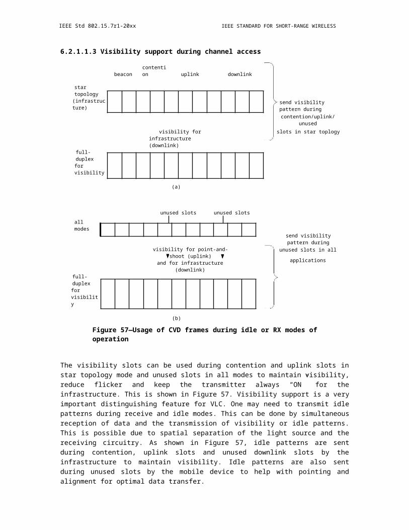
OPTICAL COMMUNICATION IEEE Std 802.15.7r1-20xx
associate from the list of VPAN descriptors returned from the channel scan procedure is out of the scope of this standard.
Following the selection of a VPAN with which to associate, the next higher layers shall request through the MLME-ASSOCIATE.request primitive that the MLME configures the PHY and MAC PIB attributes to the values necessary for association.
A coordinator shall allow association only if macAssociationPermit is set to TRUE. Similarly, a device should attempt to associate only with a VPAN through a coordinator that is currently allowing association, as indicated in the results of the scanning procedure. If a coordinator with macAssociationPermit set to FALSE receives an association request command from a device, the command shall be rejected.
The device shall synchronize to the VPAN that it will associate with, and initiate the association procedure by sending an association request command.
Upon the reception of the association request command, the coordinator shall determine if it will accept the association request and reply an association response command to the device within TBD ms. The coordina-tor shall indicate if it accepts the request in the association response command, and if it denies the request, it shall also indicate the reason. If the coordinator accepts the request, it shall assign a unique short address for the device and include it in the association response command.
If the device does not receive the association response command after TBDms it sent the association request command, it shall resend the request. The maximal retry times is 4.
6.5.2.3.2 Disassociation
The disassociation procedure is initiated by the next higher layer by issuing the MLME-DISASSOCI-ATE.request primitive to the MLME.
When a coordinator wants one of its associated devices to leave the VPAN, the coordinator shall send a dis-association notification command frame to the device. The device shall reply a disassociation response com-mand frame to the coordinator within TBD ms.
If an associated device wants to leave the VPAN, the MLME of the device shall send a disassociation notifi-cation command frame to the coordinator. The coordinator shall reply a disassociation response command frame to the device within TBD ms.
After the device disassociated from the VPAN, the coordinator shall release the resources that has been assigned to the device, such as short address, GTS allocations, etc.
6.5.2.4 VPAN Maintenance
6.5.2.4.1 VPAN ID conflict
In some instances a situation could occur in which two VPANs exist in the same operating space with the same VPAN ID. If this conflict happens, the coordinator and its devices shall perform the VPAN ID conflict resolution procedure.
VPAN ID conflict detection
The VPAN coordinator shall conclude that a VPAN ID conflict is present if either of the following applies:
Copyright © 2011 IEEE. All rights reserved. 151
IEEE Std 802.15.7r1-20xx IEEE STANDARD FOR SHORT-RANGE WIRELESS
A beacon frame is received by the VPAN coordinator with the VPAN coordinator subfield set to one and the VPAN ID equal to macVPANId
A VPAN ID conflict notification command is received by the VPAN coordinator from an associ-ated device on its VPAN.
A device that is associated through the VPAN coordinator shall conclude that a VPAN ID conflict is present if the following applies;
A beacon frame is received by the device with the VPAN coordinator subfield set to one, the VPAN ID equal to macVPANId, and an address that is equal to neither macCoordShortAddress nor macCoordExtendedAd-dress.
VPAN ID conflict resolution
On the detection of a VPAN ID conflict by a device, it shall generate the VPAN ID conflict notification com-mand and send it to its coordinator. The coordinator shall confirm its receipt by sending an ACK frame. Once the device has received the ACK frame from the coordinator, the MLME shall issue an MLME-SYNC -LOSS.indication primitive with the LossReason parameter set to VPAN_ID_CONFLICT. If the device does not receive an ACK frame, the MLME shall not inform the next higher layer of the VPAN ID conflict.
On reception of the VPAN ID conflict notification command by the coordinator, the coordinator is notified of the VPAN ID conflict and the MLME shall issue an MLME-SYNC-LOSS.indication to its next higher layer with the LossReason parameter set to VPAN_ID_CONFLICT.
On receipt of the MLME-SYNC-LOSS.indication primitive with the LossReason parameter set to VPAN_ ID_CONFLICT by the next higher layer of the coordinator, it shall first perform a scan and then select a new VPAN ID based on the result of the scan and provide the new VPAN ID to the MLME by issu-ing a MLME-START.request primitive with the CoordRealignment parameter set to TRUE. The MLME shall perform a VPAN realignment on receipt of the MLME-START.request primitive with the CoordRe-alignment parameter set to TRUE.
6.5.2.4.2 VPAN realignment
For the coordinator, it shall generate a coordinator realignment command on receipt of a MLME-START.request primitive with the CoordRealignment parameter set to TRUE. The coordinator shall broad-cast the coordinator realignment command containing the new parameters. When a device receives the coor-dinator realignment command, the MLME of the device shall notify its next higher layer the VPAN realignment by issuing a MLME-SYNC-LOSS.indication primitive.
The coordinator realignment command shall indicate in which superframe the new parameters to be in effect by setting a proper value to the CountDown field in the beacon frame. Both the coordinator and devices shall make sure the new parameters are properly set at the starting point of the effective superframe. The coordi-nator and the devices shall set the new parameters by issuing a MLME-SET.request primitive to the MLME from the next higher layer.
6.5.2.5 Bandwidth allocation and management
A GTS allows a device to operate on the channel within a portion of the superframe that is dedicated (on the VPAN) exclusively to that device. A GTS shall be allocated only by the coordinator, and it shall be used only for communications between the coordinator and a device associated with the VPAN through the coor-dinator. A single GTS may extend over one or more superframe slots. The coordinator may allocate a num-ber of GTSs at the same time, provided there is sufficient capacity in the superframe.
152 Copyright © 20xx IEEE. All rights reserved.

OPTICAL COMMUNICATION IEEE Std 802.15.7r1-20xx
One or more flows can be setup between the coordinator and a device, the flows can be downlink and uplink. The allocated GTSs for a flow should meet the QoS constraints specified in the TSpec. The way in which the coordinator manages the available resources and the particular schedules it generates are out the scope of this standard. The scheduling is distributed by the coordinator in the beacon frame.
The TSpec describes the set of parameters that define the characteristics and QoS expectations of a particu-lar flow. The format of the TSpec is to be further detailed.
6.5.2.5.1 Flow establishment
A flow can be originated by the coordinator or a device. The originator shall send a flow establishment request command to the recipient to establish a flow. The recipient shall reply a flow establishment response command to the originator to notify if it accepts the flow establishment request. Both the coordinator and a device can originate a bidirectional flow, in this case, the TSpec of the reverse flow shall be included in the flow establishment response command.
When a coordinator originates a flow, it shall reserve sufficient resources for the flow before it sends the flow establishment request to the recipient device. When a coordinator receives a flow establishment request from a device, it shall first check if there is sufficient resources to meet the QoS requirements, and it accepts the request, it shall reserve sufficient resources for the flow and assign a GTS for this flow. If the coordinator denies the request from a device means that no QoS guarantees can be given, the medium access may still be performed on a priority-basis in the CAP.
The coordinator shall assign a unique Flow_ID for each flow in the VPAN. In case of the birdirectional flow, the coordinator shall assign different Flow_IDs for the forward and reverse flows respectively.
Figure 116—Message sequence chart for establish a flow
6.5.2.5.2 Flow maintenance
The coordinator can monitor the status of the link between a device and itself through the CSI feedback mechanism, and adjust the GTS allocations for the associated flows.
The coordinator may choose to offer a change in the flow parameters by sending a flow modify request com-mand to the device if it decides that the TSpec of the current flow cannot be supported. The device can trans-mit a flow modify response command to the coordinator indicating whether the offered flow parameters can be accepted or not.
If the coordinator changes the GTS allocation for a flow, the new allocation for the flow will be conveyed in the following beacons.
Copyright © 2011 IEEE. All rights reserved. 153
IEEE Std 802.15.7r1-20xx IEEE STANDARD FOR SHORT-RANGE WIRELESS
6.5.2.5.3 Flow release
If the originator of a flow decides that the flow is required to be released, it shall send a flow release request to the recipient. The recipient shall reply a flow release response command to the originator. The coordinator shall then stop assigning the GTS allocations for the flow.
Figure 117—Message sequence chart for release a flow
6.5.2.6 Acknowledgement and retransmission
Both Transmissions with acknowledgement or without acknowledgement should be supported. The next higher layer shall provide the indication whether acknowledgement is required or not when issuing the MCPS-DATA.request primitive to the MAC sublayer. All MAC command frame shall be transmitted with acknowledgement. All broadcast frames, e.g., beacons, shall be transmitted without acknowledgement.
When ACK is not required, the transmission is always assumed to be successful.
If ACK frame is not received or an ACK frame is received with an error when ACK is required, then the device shall conclude the transmission has failed and retransmission is needed.
6.5.2.7 CSI feedback and link adaptation
6.5.2.7.1 CSI feedback for MCS selection
In MAC header, a link adaptation control field is defined.
Insert Table 5-1 Link adaptation control field here
Two types of CSI feedbacks are supported.
Solicited feedback: a CSI requester request a CSI responder to feedback CSI.
Unsolicited feedback: a coordinator/device report CSI to another device/coordinator without arequest.
For solicited feedback, the CSI requester may set the MCS request to 1 to request a responder to provide MCS recommendation. In each MCS request, the requester shall set the MSI (MCS sequence index) subfield in the link adaptation control field to a value in the range 0 to 6. How the requester chooses the MSI value is implementation dependent.
154 Copyright © 20xx IEEE. All rights reserved.
OPTICAL COMMUNICATION IEEE Std 802.15.7r1-20xx
On receipt of a frame with the MCS request subfield equal to 1, an CSI responder initiates computation of the MCS estimate and labels the result of this computation with the MSI value. The MFB responder includes the received MSI value in the feedback sequence index field of the corresponding response frame. The sug-gested MCS level is transmitted in MCS feedback field.
For unsolicited feedback, a device/coordinator feedbacks a suggest MCS level without being requested. In this case, feedback sequence index is set to 7, and suggested MCS level is transmitted in MCS feedback field.
After CSI feedback is obtained by the transmitter, it selects a MCS level for future transmissions. The selected MCS level may or may not be the one suggested by the receiver.
The selected MCS level for data transmission is indicated in PHY header.
6.5.2.7.2 CSI feedback for bit-loading
FFS
6.5.2.7.3 CSI feedback for MIMO operation
FFS
6.5.2.7.4 Interference coordination
Interference coordination is considered mainly for coordinated topology.
6.5.2.7.5 Mobility and handover
FFS
6.5.3 Relaying
6.5.4 Coordinated network
6.5.4.1 Channel access
See clause 5.4.1.
6.5.4.2 VPAN establishment
Establishing a new VPAN shall start with resetting the MAC sublayer and the PHY layer. The next higher layer of the prospective coordinator shall isuss a MLME-RESET.request primitive to its MLME. The MLME turn off the transceiver by issuing a PLME-SET- TRX-STATE.request to the PHY layer, and then the MAC sublayer is set to its initial conditions, clearing all internal variables to their default values.
The MLME of the prospective coordinator shall respond with a MLME-RESET.confirm primitive to notify the next higher layer the result of the reset operation.
After the reset, the next higher layer of the prospective coordinator shall issue a MLME- SCAN.request primitive to require the MLME to perform a scan to discover other VPANs by obtaining their corresponding beacon frames. The MLME shall perform the scan and report the result of the scan to its next higher layer with a MLME-SCAN.confirm primitive.
Copyright © 2011 IEEE. All rights reserved. 155

IEEE Std 802.15.7r1-20xx IEEE STANDARD FOR SHORT-RANGE WIRELESS
After the scan, the next higher layer shall choose a VPAN ID for the new VPAN. The next higher layer pro-vide the new VPAN ID along with other parameters to the MLME by issuing a MLME-START.request primitive. On receipt of MLME- START.request primitive, the MLME shall begin to send beacon frames and operate as a coordinator and the VPAN is established.
6.5.4.3 Association and disassociation
6.5.4.3.1 Association
A device shall perform a passive scan procedure (see clause 5.4.2.1) after it is powered on.
A device may fail to detect any beacon since it locates in the overlapped coverage of different VPANs. If there is no VPAN is detected, the next higher layer may request the MLME to send a beacon request com-mand. After sending the beacon request command, the device shall continue to scan the channel to discover beacon frames or additional beacon frames during Tcoordscan.
A coordinator receives such beacon request commands from a device shall allocate a GTS in the CFP to transmit an additional beacon frame as soon as possible. The additional beacon frame shall be the same as the beacon sent in the BP in the same superframe. The BeaconType field in the beacon frame can be used to identify the type of the beacons. If the coordinator does not receive any association request within TBD ms, it may stop transmit the additional beacons.
The results of the channel scan would have then been used for choosing a suitable VPAN. The algorithm for selecting a suitable VPAN with which to associate from the list of VPAN descriptors returned from the chan-nel scan procedure is out of the scope of this standard.
Following the selection of a VPAN with which to associate, the next higher layers shall request through the MLME-ASSOCIATE.request primitive that the MLME configures the PHY and MAC PIB attributes to the values necessary for association.
The MAC sub-layer of an unassociated device shall initiate the association procedure by sending an associa-tion request command to the coordinator of an existing VPAN.
Upon the reception of the association request command, the coordinator shall determine if it will accept the association request and reply an association response command to the device within TBD ms. The coordina-tor shall indicate if it accepts the request in the association response command, and if it denies the request, it shall also indicate the reason. If the coordinator accepts the request, it shall assign a unique short address for the device and include it in the association response command.
If the device does not receive the association response command after TBD ms it sent the association request command, it shall resend the request. The maximal retry times is 4.
6.5.4.3.2 Disassociation
The disassociation procedure is initiated by the next higher layer by issuing the MLME-DISASSOCI-ATE.request primitive to the MLME.
When a coordinator wants one of its associated devices to leave the VPAN, the coordinator shall send a dis-association notification command frame to the device. The device shall reply a disassociation response com-mand frame to the coordinator within TBD ms.
156 Copyright © 20xx IEEE. All rights reserved.
OPTICAL COMMUNICATION IEEE Std 802.15.7r1-20xx
If an associated device wants to leave the VPAN, the MLME of the device shall send a disassociation notifi-cation command frame to the coordinator. The coordinator shall reply a disassociation response command frame to the device within TBD ms.
After the device disassociated from the VPAN, the coordinator shall release the resources that has been assigned to the device, such as short address, GTS allocations, etc.
6.5.4.4 VPAN Maintenance
6.5.4.4.1 VPAN ID conflict
In some instances a situation could occur in which two VPANs exist in the same operating space with the same VPAN ID. If this conflict happens, the coordinator and its devices shall perform the VPAN ID conflict resolution procedure.
VPAN ID conflict detection
A VPAN ID conflict shall be detected as specified in clause 5.4.4.1.1
Resolution
A VPAN ID conflict shall be resolved as specified in clause 5.4.4.1.2.
6.5.4.4.2 VPAN realignment
VPAN realignment shall be performed as specified in clause 5.4.4.2.
6.5.4.5 Bandwidth allocation and management
See clause 5.4.5.
6.5.4.6 Acknowledgement and retransmission
See clause 5.4.6.
6.5.4.7 CSI feedback and link adaptation
6.5.4.7.1 CSI feedback for MCS selection
In MAC header, a link adaptation control field is defined.
Insert Table 5-2 Link adaptation control field here
Two types of CSI feedbacks are supported.
Solicited feedback: a CSI requester request a CSI responder to feedback CSI.
Unsolicited feedback: a coordinator/device report CSI to another device/coordinator without arequest.
For solicited feedback, the CSI requester may set the MCS request to 1 to request a responder to provide MCS recommendation. In each MCS request, the requester shall set the MSI (MCS sequence index) subfield
Copyright © 2011 IEEE. All rights reserved. 157

IEEE Std 802.15.7r1-20xx IEEE STANDARD FOR SHORT-RANGE WIRELESS
in the link adaptation control field to a value in the range 0 to 6. How the requester chooses the MSI value is implementation dependent.
On receipt of a frame with the MCS request subfield equal to 1, an CSI responder initiates computation of the MCS estimate and labels the result of this computation with the MSI value. The MFB responder includes the received MSI value in the feedback sequence index field of the corresponding response frame. The sug-gested MCS level is transmitted in MCS feedback field.
For unsolicited feedback, a device/coordinator feedbacks a suggest MCS level without being requested. In this case, feedback sequence index is set to 7, and suggested MCS level is transmitted in MCS feedback field.
After CSI feedback is obtained by the transmitter, it selects a MCS level for future transmissions. The selected MCS level may or may not be the one suggested by the receiver.
The selected MCS level for data transmission is indicated in PHY header.
6.5.4.7.2 CSI feedback for bit-loading
FFS
6.5.4.7.3 CSI feedback for MIMO operation
FFS
6.5.4.8 Interference coordination
6.5.4.8.1 General description
The VPANs managed by the same global controller (GC) forms a VPAN cluster. In this clause, only the intra-cluster interference coordination are specified. At the beginning of the VPAN establishment, the boundary of the superframe of all the VPANs in the same cluster should be aligned.
A device and the coordinator should be capable of detecting the presence of other neighboring VPANs that have the overlapped coverage with the VPAN it associated with. The coordinator is responsible for collect-ing the interference information from all devices associated with it and report to the global controller. The coordinator should be capable of receive the resource coordination information from the global controller, which will be used for scheduling the allocations in the superframe.
The interference coordination is executed based on the coordination period. The interference information that is reported in current coordination period should be used for the resource coordination during next coor-dination period. The duration of a coordination period Tcoordination shall equal to the length of TBD super-frame.
The interference coordination procedure includes the following mechanisms.
Interference measurement and report
Resource Coordination
Interference parameters/resource coordination update
158 Copyright © 20xx IEEE. All rights reserved.
OPTICAL COMMUNICATION IEEE Std 802.15.7r1-20xx
6.5.4.8.2 Interference measurement and report
Both a device and the coordinator can detect and measure the interference. The measurement is based on the detection of beacons or reference signals. When a device suffering from interference from neighboring VPANs detects that the interference level excess the predefined threshold, and it does not decide to initiate a handover to a neighboring coordinator, it shall report the detected interference to the coordinator by sending an interference report command. The criteria for a device to decide whether the handover should be per-formed refers to clause 5.6.9. The coordinator gathers the interference information and reports to the global controller every TBD superframes (i.e., a coordination period).
6.5.4.8.3 Resources coordination
The global controller allocates resources for the VPANs that it manages and notify the coordinators about the allocations. The coordinator that does not receive the allocations information from the global controller can makes the scheduling by itself; the coordinator that receive the allocations information from the network controller shall take the allocation information into account while makes the scheduling. The rules and crite-ria for resource coordination is out of the scope of this standard.
6.5.4.8.4 Interference coordination update
Both the device and the coordinator shall be capable of updating the interference information.
When a device suffering from interference from neighboring VPANs that has reported the interference infor-mation to the coordinator detects the change of parameters related to the interference, it shall update the parameters related to the measured interference to the coordinator by sending an interference The coordina-tor gathers the updated interference information and reports to the network controller along with new inter-ference information every coordination period.
If a device that is suffering from interference from neighboring VPAN and is involved in the coordination disassociates with the VPAN, the coordinator shall be able to learn the leave of that device as soon as possi-ble and report this to the global controller in next report event.
Figure 118—An example of the interference coordination
6.5.4.9 Mobility and handover
Two scenarios are considered. First is LIFI only scenario, therefore handover is made between VLC VPAN and VLC VPAN. Second is LIFI + WIFI heterogeneous network.
Copyright © 2011 IEEE. All rights reserved. 159

IEEE Std 802.15.7r1-20xx IEEE STANDARD FOR SHORT-RANGE WIRELESS
6.5.4.9.1 Scenario 1: LIFI only
Two types of handover are supported,
Type1, over the air: handover is initiated by device
Type2, over the backhaul, handover is initiated by controller
Type 1 handover: over the air
After association to a serving coordinator, a device may scan the area for available neighboring coordinators and perform received signal strength (RSS) measurement. The measurement is based on beacons or refer-ence signals.
A device may perform alpha-filtering on the measurements based on
RSS_n=(1-?) RSS_(n-1)+?M_n
Where M_n is the latest received measurement result from the physical layer; RSS_n is the updated filtered measurement result, that is used for evaluation of reporting criteria or for measurement reporting; RSS_(n-1) is the old filtered measurement result; ? is a filtering-coefficient that can be configured.
If the RSS of neighbor cells satisfy
RSS_target-RSS_associate>?_th1
Then the device should initiate the handover to the target coordinator. Here RSS_target is the RSS of the tar-get coordinator and RSS_associate is the RSS of the associated coordinator and ?_th1 is a predefined thresh-old.
Once the handover is initiated by the device, it sends a re-association request to the target coordinator. The device uses the re-association request to request association as well as to send its preferred QoS require-ments to the target coordinator.
In the association response message, the target coordinator indicates whether the request is permitted. Besides, the target coordinator also inform the QoS resources allocated to the device, or suggests alternate level of QoS the target coordinator can support.
The previous coordinator may continue to send the packets that have been store in the buffer to the device. The device may receive these packets to its best effort. If the previous coordinator does not received acknowledgement from the device for N consecutive frames, then the previous coordinator consider the device has left the VPAN and the transmission is ceased.
160 Copyright © 20xx IEEE. All rights reserved.
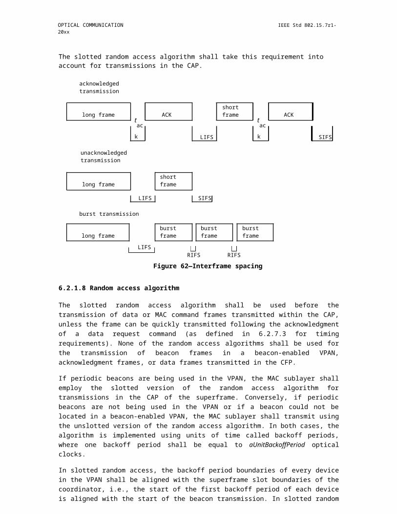
OPTICAL COMMUNICATION IEEE Std 802.15.7r1-20xx
Figure 119—handover: over the air
Type 2 handover: over the backhaul
After association to a serving coordinator, a device may scan the area for available neighboring coordinators and perform received signal strength (RSS) measurement. The measurement is based on beacons or refer-ence signals.
A device may perform alpha-filtering on the measurements based on
RSS_n=(1-?) RSS_(n-1)+?M_n
Where M_n is the latest received measurement result from the physical layer; RSS_n is the updated filtered measurement result, that is used for evaluation of reporting criteria or for measurement reporting; RSS_(n-1) is the old filtered measurement result; ? is a filtering-coefficient that can be configured.
If the RSS of neighbor cells satisfy
RSS_associate-RSS_target>?_th2
Then the device should send RSS measurement report to the associated coordinator periodically. Here RSS_target is the RSS of the target coordinator and RSS_associate is the RSS of the associated coordinator and ?_th2 is a predefined threshold.
The coordinator can send the measurement report to the global controller together with the QoS requirement of the device.
If the global controller decides to handover the device to the target coordinator, it sends its decision to the current coordinator. It also notify the target coordinator about the upcoming handover together with QoS requirement.
Current coordinator send handover command frame to the device.
Then the device send re-association request to the target device.
In the association response message, the target coordinator confirms the handover. Besides, the target coor-dinator also inform the QoS resources allocated to the device, or suggests alternate level of QoS the target coordinator can support.
Copyright © 2011 IEEE. All rights reserved. 161
IEEE Std 802.15.7r1-20xx IEEE STANDARD FOR SHORT-RANGE WIRELESS
Figure 120—Type 2 handover: over the
backhaul 6.5.4.9.2 Scenario 2: LIFI + WIFI
Figure 121—Handover for heterogeneous RF+VLC network
For heterogeneous operations of LIFI and WIFI, three types of handover are envisioned.
Type1 handover: WIFI => WIFI + VPAN
Type2 handover: WIFI + VPAN => WIFI
Type3 handover: WIFI + VPAN1 => WIFI + VPAN2
Type1 handover: WIFI => WIFI + VPAN
Similar to association procedure, the device can send an association request to a target coordinator is the RSS meet the requirement.
Type2 handover: WIFI + VPAN => WIFI
After associating to a serving coordinator, a device may scan the area for available neighboring coordinators and perform received signal strength (RSS) measurement. The measurement is based on beacons or refer-ence signals.
162 Copyright © 20xx IEEE. All rights reserved.
OPTICAL COMMUNICATION IEEE Std 802.15.7r1-20xx
A device may perform alpha-filtering on the measurements based on
RSS_n=(1-?) RSS_(n-1)+?M_n
Where M_n is the latest received measurement result from the physical layer; RSS_n is the updated filtered measurement result, that is used for evaluation of reporting criteria or for measurement reporting; RSS_(n-1) is the old filtered measurement result; ? is a filtering-coefficient that can be configured.
If no neighbor coordinator with satisfactory RSS can be found and meanwhile the RSS of associated coordi-nator is falls below a predefined threshold
RSS_associate<?_th3
Then the device should send RSS measurement report to the associated coordinator periodically. Here RSS_associate is the RSS of the associated coordinator and ?_th3 is a predefined threshold.
The coordinator can send the measurement report to the global controller together with the QoS requirement of the device.
If the global controller decides to handover the device to WIFI only, it sends its decision to the current coor-dinator and steer traffic to the WIFI.
Current coordinator then sends dissociation command frame to the device.
Type3 handover: WIFI + VPAN1 => WIFI + VPAN2
Same as scenario 1, can be either over-the-air or over-the-backhaul.
6.5.5 Heterogeneous Operation of different OWC PHY modes
6.5.6 MAC frame formats
The MAC frame format is composed of a MHR, a MSDU and a MFR. The specific fields of each component is for further study.
6.5.7 Command frames
6.5.8 Primitives for data service
Primitives for management service
Copyright © 2011 IEEE. All rights reserved. 163

IEEE Std 802.15.7r1-20xx IEEE STANDARD FOR SHORT-RANGE WIRELESS
6.6 PureLiFi MAC frame formats (16/310r0)
The format of the MAC frames is specified in this clause. A STA shall be able to properly construct a subset of the frames specified in this clause for transmission and to decode a subset of the frames specified in this clause upon validation following reception. All STAs shall be able to validate every received frame using the frame check sequence (FCS) and to interpret certain fields from the MAC headers of all frames.
Each frame consists of the following basic components:
a) A MAC header, which comprises frame control, acknowledgment information, address, and sequence control information;
b) A variable length frame body, which contains information specific to the frame type and subtype;
c) A FCS, which contains an IEEE 32-bit CRC.
6.6.1 Conventions
The MPDUs or frames in the MAC sublayer are described as a sequence of fields in specific order. Each fig-ure in this clause depicts the fields/subfields as they appear in the MAC frame and in the order in which they are passed to the physical layer convergence procedure (PLCP), from left to right.
In figures, all bits within fields are numbered, from 0 to k, where the length of the field is k + 1 bits. The octet boundaries within a field can be obtained by taking the bit numbers of the field modulo 8. Octets within numeric fields that are longer than a single octet are depicted in increasing order of significance, from lowest numbered bit to highest numbered bit. The octets in fields longer than a single octet are sent to the PLCP in order from the octet containing the lowest numbered bits to the octet containing the highest num-bered bits.
Any field containing a CRC is an exception to this convention and is transmitted commencing with the coef-ficient of the highest-order term.
MAC addresses are assigned as ordered sequences of bits. The Individual/Group bit is always transferred first and is bit 0 of the first octet.
Values specified in decimal are coded in natural binary unless otherwise stated. The values in Table 1 are in binary, with the bit assignments shown in the table. Values in other tables may be shown in decimal notation.
Reception, in references to frames or fields within frames (e.g., received Beacon frames or a received Duration/ID field), applies to MPDUs or MAC management protocol data units (MMPDUs) indicated from the PHY layer without error and validated by FCS within the MAC sublayer. Without further qualification, reception by the MAC sublayer implies that the frame contents are valid, and that the protocol version is supported, with no implication regarding frame addressing or regarding whether the frame type or other fields in the MAC header are meaningful to the MAC entity that has received the frame.
6.6.2 5.8.2 General frame format
The MAC frame format comprises a set of fields that occur in a fixed order in all frames. Figure 5.8.2.1 depicts the general MAC frame format. All fields, except for the Frame Body (used for delivering payload information and data), are present in all types of MAC frames. Each field is defined in 5.8.3. The format of each of the individual subtypes of each frame type is defined in 5.8.4.
The Frame Body field is of variable size. The maximum frame body size is determined by the maximum MSDU size (2304 octets) plus any overhead from security encapsulation.
164 Copyright © 20xx IEEE. All rights reserved.
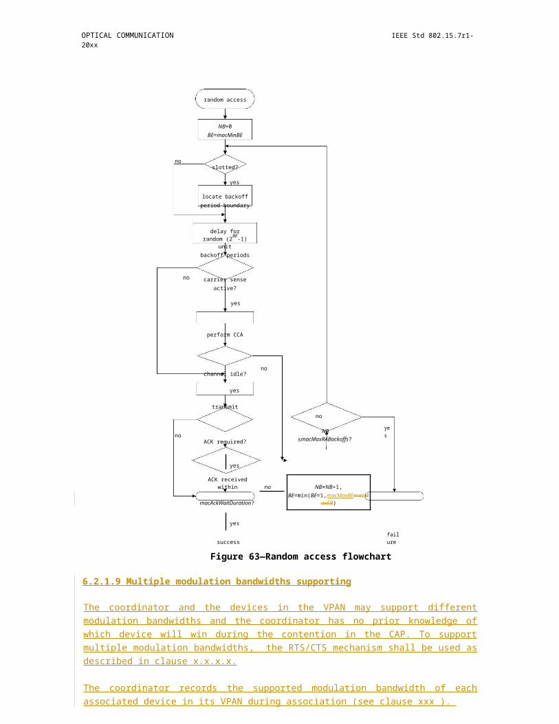
OPTICAL COMMUNICATION IEEE Std 802.15.7r1-20xx
INSERT FIGURE 5.8.2.1 16/310r0 HERE
6.6.3 Frame fields
6.6.3.1 Frame Control field
The Frame Control field consists of the following subfields: Protocol Version, Type, Subtype, and a Reserved subfield. The format of the Frame Control field is illustrated in Fig. 5.8.3.1.1.
INSERT FIGURE 5.8.3.1.1 16/310r0 HERE
6.6.3.1.1 Protocol Version
Two-bit field indicating the MAC protocol frame version. The 802.15.7 protocol version is indicated with the value of '00' for this field, while the current 802.15.7r1 protocol version is indicated with the value '10'.
6.6.3.1.2 Type and Subtype fields
The Type field is 2 bits in length, and the Subtype field is 4 bits in length. The Type and Subtype fields together identify the function of the frame. There are two frame types in the current MAC layer protocol description: data, and management. Each of the frame types has several defined subtypes. Table 5.8.3.1.2.1 defines the valid combinations of type and subtype. (The numeric values in Table 1 are shown in binary.)
Insert Table 5.8.3.1.2.1: Type and Subtype field values for different frame types
6.6.3.1.3 Reserved field
The Reserved field constitutes the rest of the Frame Control field and has been introduced for possible extension of the frame control field.
6.6.3.2 Reserved field
Two octets reserved for possible protocol frame extension.
6.6.3.3 Acknowledgment Information (Ack Info) field
In all existing frame types and subtypes (except for the Beacon frame), the Ack Info field contains the infor-mation necessary to identify the MSDU or MMPDU sequence number and the station which transmitted the acknowledged packet. The information in this field has the format depicted in Fig. 5.8.3.3.1.
INSERT FIGURE 5.8.3.3.1 16/310r0 HERE
6.6.3.3.1 Sequence #
Bits 0 to 7 contain the address of the STA which transmitted the packet which is being acknowledged. In the uplink transmission, these bits identify the STA transmitting the current packet as the acknowledgment can be only for packets transmitted by the AP.
6.6.3.3.2 Reserved
Bits 8 to 11 are reserved for possible frame extension or functionality extension for packet fragmentation support.
Copyright © 2011 IEEE. All rights reserved. 165

IEEE Std 802.15.7r1-20xx IEEE STANDARD FOR SHORT-RANGE WIRELESS
6.6.3.3.3 Sequence Number
Bits 12 to 23 identify the number of the packet which is being acknowledged.
6.6.3.3.4 ACK
Bit 24 is set to '1' when a packet is being acknowledged with the current frame, and set to '0' otherwise.
Bit 25 is set to '1' when the last Beacon frame reception is being acknowledged, and set to '0' otherwise.
6.6.3.3.5 Reserved
Bits 26 to 31 are reserved for possible future extension of the functionality specification.
6.6.3.4 Receiver Address field
The Receiver Address field is a 48-bit field indicating the network address of the STA for which the trans-mitted packet is intended.
6.6.3.5 Transmitter Address field
The Transmitter Address field is a 48-bit field indicating the network address of the STA transmitting the packet.
6.6.3.6 Reserved field
This field contains 48 bits which are reserved for future references in an extension of the MAC protocol.
6.6.3.7 Sequence Control field
In data frames, the Sequence Control field contains the information necessary to identify the MSDU or MMPDU sequence number. The information in this field has the format depicted in Fig. 5.8.3.7.1. Bits 4 to 15 identify the packet sequence number, while bits 0 to 3 are reserved for possible future extensions of the protocol functionality such as packet fragmentation support. This same information is used by the receiving station and placed in the Ack Info field of a subsequent frame used for package acknowledgment.
INSERT FIGURE 5.8.3.7.1 HERE
6.6.3.8 Reserved field
This field contains 16 bits which are reserved for future references in an extension of the MAC protocol.
6.6.3.9 5.8.3.9 Frame Body field
The Frame Body is a variable length field that contains information specific to individual frame types and subtypes as defined in subclause 5.8.4. The minimum frame body is 0 octets. The maximum length frame body is defined by the maximum length (MSDU + ICV + higher layer overhead), where ICV stands for integrity check value.
6.6.3.10 Frame check sequence (FCS) field
The FCS field is a 32- bit field containing a 32-bit CRC. The FCS is calculated over all the fields of the MAC header and the Frame Body field. These are referred to as the calculation fields.
166 Copyright © 20xx IEEE. All rights reserved.
OPTICAL COMMUNICATION IEEE Std 802.15.7r1-20xx
The FCS is calculated using the following standard generator polynomial of degree 32:
G(x) = x32 + x26 + x23 + x22 + x16 + x12 + x11 + x10 + x8 + x7 + x5 + x4 + x2 + x +
1 The FCS is the ones complement of the sum (modulo 2) of the following:
a) The remainder of xk × (x31 + x30 + x29 + …+ x2 + x + 1) divided (modulo 2) by G(x), where k is the number of bits in the calculation fields, and
b) The remainder after multiplication of the contents (treated as a polynomial) of the calculation fields by x32 and then division by G(x).
The FCS field is transmitted commencing with the coefficient of the highest-order term.
As a typical implementation, at the transmitter, the initial remainder of the division is preset to all ones and is then modified by division of the calculation fields by the generator polynomial G(x). The ones comple-ment of this remainder is transmitted, with the highest-order bit first, as the FCS field.
At the receiver, the initial remainder is preset to all ones and the serial incoming bits of the calculation fields and FCS, when divided by G(x), results in the absence of transmission errors, in a unique nonzero remainder value. The unique remainder value is the polynomial:
x31 + x30 + x26 + x25 + x24 + x18 + x15 + x14 + x12 + x11 + x10 + x8 + x6 + x5 + x4 + x3 + x + 1
6.6.4 Specific Frame Formats
6.6.4.1 Management Frames Format
6.6.4.1.1 Management Frames Information Components
5.8.4.1.1.1 Beacon Frame Format
The Beacon frame body contains the following information in the presented order:
Insert Table 5.8.4.1.1.1.1: Beacon Frame Body here
5.8.4.1.1.2 IBSS ATIM Frame Format
The body of an IBSS ATIM management frame is null.
5.8.4.1.1.3 Disassociation Frame Format
The Disassociation frame body contains the following information in the presented order:
Insert Table 5.8.4.1.1.3.1: Disassociation Frame Body
5.8.4.1.1.4 Association Request Frame Format
The Association Request frame body contains the following information in the presented order:
Insert Table 5.8.4.1.1.4.1: Association Request Frame Body
5.8.4.1.1.5 Association Response Frame Format
Copyright © 2011 IEEE. All rights reserved. 167

IEEE Std 802.15.7r1-20xx IEEE STANDARD FOR SHORT-RANGE WIRELESS
The Association Response frame body contains the following information in the presented
order: Insert Table 5.8.4.1.1.5.1: Association Response Frame Body
5.8.4.1.1.6 Reassociation Request Frame Format
The Reassociation Request frame body contains the following information in the presented
order: Insert Table 5.8.4.1.1.6.1: Reassociation Request Frame Body
5.8.4.1.1.7 Reassociation Response Frame Format
The Reassociation Response frame body contains the following information in the presented
order: Insert Table 5.8.4.1.1.7.1: Reassociation Response Frame Body
5.8.4.1.1.8 Probe Request Frame Format
The Probe Request frame body contains the following information in the presented
order: Insert Table 5.8.4.1.1.8.1: Probe Request Frame Body
5.8.4.1.1.9 Probe Response Frame Format
The Probe Response frame body contains the following information in the presented
order: Insert Table 5.8.4.1.1.9.1: Probe Response Frame Body
5.8.4.1.1.10 Authentication Frame Format
The Probe Request frame body contains the following information in the presented
order: Insert Table 5.8.4.1.1.10.1: Authentication Frame Body
Insert Table 5.8.4.1.1.10.2: Challenge text information
5.8.4.1.1.11 Deauthentication Frame Format
The Deauthentication frame body contains the following information in the presented
order: Insert Table 5.8.4.1.1.11.1: Deauthentication Frame Body
5.8.4.1.1.12 Action Frame Format
The Action frame body contains the following information in the presented
order: Insert Table 5.8.4.1.1.12.1: Action Frame Body
6.6.4.1.2 Management Frame Body Fields
5.8.4.1.2.1 Authentication Algorithm Number Field
The Authentication algorithm number is a 16-bit field, which indicates a single algorithm used for authenti-cation (see Fig. 5.8.4.1.2.1.1). Two values have been defined:
168 Copyright © 20xx IEEE. All rights reserved.
OPTICAL COMMUNICATION IEEE Std 802.15.7r1-20xx
'0' ? Open System
'1' ? Shared Key
'2-65536' ? Reserved for future use
INSERT FIGURE 5.8.4.1.2.1.1 HERE
5.8.4.1.2.2 Authentication Transaction Sequence Number Field
The authentication transaction sequence number is a 16-bit field, which indicates the current step in a multi-step authentication procedure (see Fig. 5.8.4.1.2.2.1).
INSERT FIGURE 5.8.4.1.2.2.1 HERE
5.8.4.1.2.3 Beacon Interval Field
INSERT FIGURE 5.8.4.1.2.3.1 HERE
The beacon interval field is a 16-bit field, which indicates the interval in time units between two consecutive beacon frames (see Fig. 5.8.4.1.2.3.1).
5.8.4.1.2.4 Capability Information Field
The beacon interval field is a 16- bit field, which indicates the AP capabilities with regards to optional ser-vices (see Fig. 5.8.4.1.2.4.1). The field is left unspecified and reserved for future use.
INSERT FIGURE 5.8.4.1.2.4.1 HERE
5.8.4.1.2.5 Current AP Address Field
The current AP address field is a 48-bit field, which indicates the address of the AP with which the STA is currently associated. The field is illustrated in Fig. 5.8.4.1.2.5.1.
INSERT FIGURE 5.8.4.1.2.5.1 HERE
5.8.4.1.2.6 Listen Interval Field
The listen interval field is a 16-bit field, which indicates to the AP how often the STA wakes up to listen for Beacon management frames. The field is illustrated in Fig. 5.8.4.1.2.6.1. The value of the field is expressed in units of Beacon Intervals.
INSERT FIGURE 5.8.4.1.2.6.1 HERE
5.8.4.1.2.7 Reason Code Field
The Reason Code is a 16-bit field, which indicates the reason a notification management frame of type Dis-association or Deauthentication has been generated. The field is illustrated in Fig. 5.8.4.1.2.7.1. The values of the field are specified in Table 5.8.4.1.2.7.1.
INSERT FIGURE 5.8.4.1.2.7.1 HERE
Copyright © 2011 IEEE. All rights reserved. 169
IEEE Std 802.15.7r1-20xx IEEE STANDARD FOR SHORT-RANGE WIRELESS
Insert Table 5.8.4.1.2.7.1: Reason codes
Reason CodeMeaning
0 Reserved
1 Unspecified reason
2 Previous authentication no longer valid
3 Deauthenticated because sending STA is leaving (or has left) IBSS or ESS
4 Disassociated due to inactivity
5 Disassociated because AP is unable to handle all currently associated STAs
6 Class 2 frame received from nonauthenticated STA
7 Class 3 frame received from nonassociated STA
8 Diasassociated because sending STA is leaving (or has left) BSS
9 STA requesting (re)association is not authenticated with responding STA
10 - 12 Reserved
13 Invalid information element
14 Message integrity code (MIC) failure
15 4-Way Handshake timeout
16 Group Key Handshake timeout
17 Information element in 4-Way Handshake different from (Re)Association Request / Probe Response / Beacon frame
18 Invalid group cipher
19 Invalid pairwise cipher
20 Invalid AKMP
21 Unsupported RSN information element version
22 Invalid RSN information element capabilities
23 IEEE 802.1X authentication failed
24 Cipher suite rejected because of the security policy
25-35 Reserved
36 Requested from peer STA as the STA is leaving the BSS (or resetting)
170 Copyright © 20xx IEEE. All rights reserved.
OPTICAL COMMUNICATION IEEE Std 802.15.7r1-20xx
37 Requested from peer STA as it does not want to use the mechanism
38 Requested from peer STA as the STA using wrong mechanism
39 Requested from peer STA due to timeout
40-44 Reserved
45 Peer STA does not support the requested cipher suite
46 - 65535Reserved
5.8.4.1.2.8 Association ID (AID) Field
The AID field is a 16-bit field, which is a station ID assigned by an AP during association. The field is illus-trated in Fig. 5.8.4.1.2.8.1. The value of the field is in the range 1 - 2007 and is placed in the 14 LSBs of the AID field, with the two MSBs of the field set to '11'.
INSERT FIGURE 5.8.4.1.2.8.1 HERE
5.8.4.1.2.9 Status Code Field
The Status Code field is a 16-bit field used in response to a management frame in order to indicate the suc-cess or the failure of the operation. The field is illustrated in Fig. 5.8.4.1.2.9.1. The possible values of this field are presented in Table 5.8.4.1.2.9.1.
INSERT FIGURE 5.8.4.1.2.8.1 HERE
Insert Table 5.8.4.1.2.9.1: Status codes
Reason CodeMeaning
0 Successful
1 Unspecified failure
2-9 Reserved
10 Cannot support all requested capabilities in the Capability Information field
11 Reassociation denied due to inability to confirm that association exists
12 Association denied due to reasons outside the scope of this standard
13 Responding STA does not support the specified authentication algorithm
14 Received an unexpected authentication transaction sequence number
15 Authentication rejected because of challenge failure
16 Authentication rejected due to timeout waiting for next frame in sequence
17 Association denied because AP is unable to handle additional associated STAs
Copyright © 2011 IEEE. All rights reserved. 171
IEEE Std 802.15.7r1-20xx IEEE STANDARD FOR SHORT-RANGE WIRELESS
18 Association denied due to requesting STA not supporting all basic data rates
19 - 33 Reserved
34 Association denied due to excessive frame loss rate / poor channel conditions
35 - 36 Reserved
37 The request has been declined
38 The request has not been successful due to invalid parameter values
39 Reserved
40 Invalid information element (content is invalid)
41 Invalid group cipher
42 Invalid pairwise cipher
43 Invalid AKMP
44 - 45 Reserved
46 Cipher suite rejected because of security policy
47 - 48 Reserved
49 The destination STA is not within this BSS
50 Reserved
51 Association denied because the Listen Interval is too large
52 - 65535Reserved
5.8.4.1.2.10 Timestamp Field
The Timestamp field is a 64-bit field representing the value of a timing synchronization function. The field is illustrated in Fig. 5.8.4.1.2.10.1.
INSERT FIGURE 5.8.4.1.2.10.1
5.8.4.1.3. Management Frame Information Elements
The information elements are defined to have a common general format which consists of 1 octet specifying the element ID, 1 octet specifying the length of the element field in octets, and a variable-length element field with the information contained in the respective element. The overall structure is presented in Fig. 5.8.4.1.3.1. The set of valid information elements is defined in Table 5.8.4.1.3.1.
INSERT FIGURE 5.8.4.1.3.1
Insert Table 5.8.4.1.3.1: Valid set of information elements
172 Copyright © 20xx IEEE. All rights reserved.

OPTICAL COMMUNICATION IEEE Std 802.15.7r1-20xx
Information ElementElement IDLength (in octets)
SSID 0 2 to 34
Supported rates1 3 to 10
Reserved2 - 6
Country 7 8 to 256
Reserved8 - 9
Request 10 2-256
BSS Load11 7
Reserved12 - 15 Reserved
Challenge Text16 3 to 255
Reserved17 - 43
TCLAS Processing443
Reserved45 - 49
Extended Supported Rates503 to 257
Reserved51 - 126
Extended Capabilities1272 to 257
Reserved128 - 220
Vendor Specific2213 to 257
Reserved222 - 255
6.6.4.2 Data Frames Format
6.6.4.3 Control Frames Format
6.6.4.3.1 Advanced Modulation Control Frame
A control frame indicating the advanced modulation capabilities of a communication node. The frame is structured as described in Fig. 5.8.4.3.1.1.
INSERT FIGURE 5.8.4.3.1.1
5.8.4.3.1.1 Adaptive Loading
A single bit indicating whether the communication node transmitting the advanced modulation control frame supports adaptive bit and energy loading:
Copyright © 2011 IEEE. All rights reserved. 173
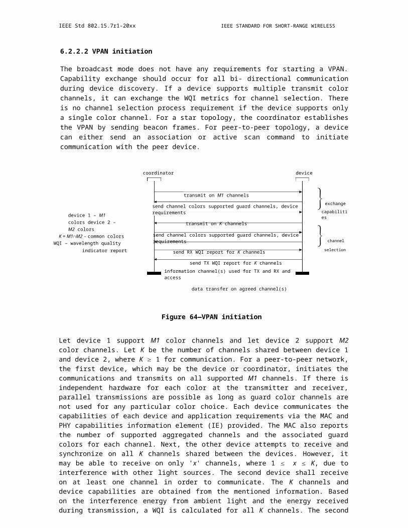
IEEE Std 802.15.7r1-20xx IEEE STANDARD FOR SHORT-RANGE WIRELESS
1 ? Adaptive bit and energy loading is supported.
0 ? Adaptive bit and energy loading is not supported.
5.8.4.3.1.2 eU
Four bits indicating if the node supports eU-OFDM. The bit value at a given position out of the four posi-tions indicates whether eU-OFDM implementation with the same number of streams as the bit position is supported. Positions are counted from left to right. For example:
1000 ? eU-OFDM with one stream only is supported.
1100 ? eU-OFDM with one and two streams only is supported
1010 ? eU-OFDM with one and three streams only is supported
1111 ? eU-OFDM with all possible streams is supported
0000 ? eU-OFDM is not supported
5.8.4.3.1.3 RPO
A single bit indicating whether the communication node transmitting the advanced modulation control rame supports RPO-OFDM:
'1' ? RPO-OFDM is supported.
'0' ? RPO-OFDM is not supported.
5.8.4.3.1.4 Analog Dimming
A single bit indicating whether the communication node transmitting the advanced modulation control frame supports analog dimming (adjusting the analog signal bias level):
'1' ? Analog dimming is supported.
'0' ? Analog dimming is not supported.
5.8.4.3.1.5 Relaying
Four bits indicating types of relaying operations the communication node transmitting the advanced modula-tion control frame supports. The first bit (B7) indicates whether relaying in FD is supported:
'1' ? Relaying in FD is supported.
'0' ? Relaying in FD is not supported.
The second bit (B8) indicates whether relaying in HD is supported:
'1' ? Relaying in HD is supported.
'0' ? Relaying in HD is not supported.
The third bit (B9) indicates whether AF relaying is supported:
174 Copyright © 20xx IEEE. All rights reserved.
OPTICAL COMMUNICATION IEEE Std 802.15.7r1-20xx
'1' ? AF relaying is supported.
'0' ? AF relaying is not supported.
The fourth bit (B10) indicates whether DF relaying is supported:
'1' ? DF relaying is supported.
'0' ? DF relaying is not supported.
5.8.4.3.1.6 MIMO
A single bit indicating whether the communication node transmitting the advanced modulation control frame supports MIMO communication:
'1' ? MIMO is supported.
'0' ? MIMO is not supported.
5.8.4.3.1.7 # of MIMO Channels
Four bits indicating the maximum number of MIMO communication channels which the communication node transmitting the advanced modulation control frame supports. A value of '0000' corresponds to 1 chan-nel, and a value of '1111' corresponds to 16 channels.
5.8.4.3.1.7 SC-FDMA
An IDFT_SIZE of bits, where IDFT_SIZE is the size of the IDFT operation used for OFDM time -domain signal generation. The bit at position k indicates whether a DFT transform of size k is supported for SC-FDMA pre-coding. For example, if IDFT_SIZE = 16, then:
'10000000000000000' - A DFT of size 1 is supported.
'00100000000000000' - A DFT of size 3 is supported.
'10100100000000000' - A DFT of size 1, 3 and 6 is supported.
'00000000000000000' - No DFT size is supported, so SC-FDMA is not supported.
5.8.4.3.2 CSI Control Frame
The CSI control frame contains the standard MAC header information defined in subclause 5.8.2. The frame body described in this clause is the only specific field. It is structured as described in Fig. 5.8.4.3.2.1.
INSERT FIGURE 5.8.4.3.2.1
5.8.4.3.2.1 MIMO Mode
A one bit value indicating whether the current CSI frame contains information relevant for the SISO or MIMO mode of operation:
1 ? MIMO mode of operation.
0 ? SISO mode of operation.
Copyright © 2011 IEEE. All rights reserved. 175

IEEE Std 802.15.7r1-20xx IEEE STANDARD FOR SHORT-RANGE WIRELESS
5.8.4.3.2.2 Adaptive Loading
A one-bit field which indicates whether the CSI in the current frame refers to the adaptive bit loading mode.
1 ? The CSI is relevant for the adaptive bit loading scheme
0 ? The CSI is relevant for the fixed bit loading scheme
5.8.4.3.2.3 Frame Info
A one-bit field indicating the type of information carried by the current frame:
'0' ? The frame carries CQIs
'1' ? The frame carrier bit loading (RATE) information
5.8.4.3.2.4 # of MIMO Channels TX
The number of MIMO channels of the transmitting node in the MIMO configuration. Values range between 0 and 15 corresponding to 1 and 16 channels, respectively. If the current CSI frame carries CQIs, then this field contains the number of the MIMO channels for the node receiving the frame. If the frame carriers bit loading (RATE) information, this field contains the number of the MIMO channels for the node transmitting the frame. This information is expected to have been exchanged via the advanced modulation control frame prior to any node issuing a CSI control frame.
5.8.4.3.2.5 # of MIMO Channels RX
The number of MIMO channels of the receiving node in the MIMO configuration. Values range between 0 and 15 corresponding to 1 and 16 channels, respectively. If the current CSI frame carries CQIs, then this field contains the number of the MIMO channels for the node transmitting the frame. If the frame carriers bit loading (RATE) information, the this field contains the number of the MIMO channels for the node receiv-ing the frame. This information is expected to have been exchanged via the advanced modulation control frame prior to any node issuing a CSI control frame.
5.8.4.3.2.6 Channel #
The MIMO channel to which the subsequent RATE/CSI information refers. In a SISO mode, this field is set to '0000'. If the Adaptive Loading field is set to '1', then this field occurs only once and is followed by the CQI / RATE information for every subcarrier of the respective MIMO channel. If the Adaptive Loading field is set to '0', then this field occurs as many times as there are MIMO channels for which relevant infor-mation needs to be exchanged followed by the relevant information as CQI / RATE values. If the Frame Info is set to '0', then this field occurs
# of MIMO Channels TX ? # of MIMO Channels RX times where the 6- bit CQI following each occurrence corresponds to the average SNR achieved for the respective combination between the corresponding MIMO transmitter and MIMO receiver. The order in which the information is arranged is | TX1 ? RX | TX1 ? RX2 |…| TX1 ? RXNMIMO| TX2 ? RX1 | TX2 ? RX2 | … |TX2 ? RXNMIMO| … | TXMMIMO ? RX1 | TXM-MIMO ? RX2 | … |TXMMIMO ? RXNMIMO |. If the Frame Info is set to '1', then this field occurs#_of_MIMO_ Channels_TX times where the information is arranged in the order | TX1 | TX2 | TX3 | … | TXMMIMO|. In each case, the occurrence of the Channel # is followed by the respective 4-bit RATE value for that TX channel.
5.8.4.3.2.6 RATE / CSI
176 Copyright © 20xx IEEE. All rights reserved.
OPTICAL COMMUNICATION IEEE Std 802.15.7r1-20xx
The RATE / CSI values for the MIMO channel specified in Channel #. If the Adaptive Loading field is set to '1', then this field occurs once for every subcarrier modulated with information on the respective MIMO channel. If the Adaptive Loading field is set to '0', then this field occurs as many times as there are MIMO channels for which relevant information needs to be exchanged and is preceded by the relevant MIMO Channel # field. If the Frame Info is set to '0', then this field occurs #_of_MIMO _Channels_TX ? #_of_MI-MO_Channels_RX times where a 6-bit CQI value is specified corresponding to the average SNR achieved for the respective combination between the corresponding MIMO transmitter and MIMO receiver. The order in which the information is arranged is | TX1 ? RX | TX1 ? RX2 |…| TX1 ? RXNMIMO| TX2 ? RX1 | TX2 ? RX2 | … |TX2 ? RXNMIMO | … | TXMMIMO ? RX1 | TXMMIMO ? RX2 | … |TXMMIMO ? RXN-MIMO |. If the Frame Info is set to '1', then this field occurs # of MIMO Channels TX times where the 4-bit RATE information is arranged in the order | TX1 | TX2 | TX3 | … | TXMMIMO |. In each case, the occur-rence of the RATE field is preceded by the respective Channel # value for that TX channel.
5.8.4.3.2 Dimming Control Frame
The frame contains control information which needs to be exchanged for the purposes of realizing dimming techniques such as RPO-OFDM and/or analog dimming.
6.7 MAC command frames
The command frames defined by the MAC sublayer are listed in Table 12. A coordinator shall be capable of transmitting and receiving all command frame types, with the exception of the GTS request command, while the requirements for a device are indicated by an “X” in Table 12. A P2P device functioning as a coordinator shall be capable of transmitting and receiving all supported command frames in a device. MAC commands shall only be transmitted in the CAP for beacon-enabled VPANs or at any time for nonbeacon-enabled VPANs.
How the MLME shall construct the individual commands for transmission is detailed in 6.7.1 through 6.7.18. MAC command reception shall abide by the procedure described in 6.2.7.2.
Table 12—Command frames
DeviceP2P
Command frameCommand name
coordinatorSubclauseidentifier
Tx Rx Tx Rx
0x01 Association request X X X 6.7.1
0x02 Association response X X X 6.7.2
0x03 Disassociation notification X X X X 6.7.3
0x04 Data request X X X 6.7.4
0x05 VPAN ID conflict notification X X X 6.7.5
0x06 Beacon request 6.7.6
0x07 Coordinator realignment X X X 6.7.7
0x08 GTS request 6.7.8
0x09 Blinking notification 6.7.9
0x0a Dimming notification X X X 6.7.10
Copyright © 2011 IEEE. All rights reserved. 177
IEEE Std 802.15.7r1-20xx IEEE STANDARD FOR SHORT-RANGE WIRELESS
Table 12—Command frames (continued)
DeviceP2P
Command frameCommand name
coordinatorSubclauseidentifier
Tx Rx Tx Rx
0x0b Fast link recovery 6.7.11
0x0c Mobility notification 6.7.12
0x0d GTS Response 6.7.13
0x0e Clock rate change notification X X X 6.7.14
0x0f Multiple channel assignment 6.7.15
0x10 Band hopping 6.2.10.2
0x11 Color stabilization timer notification X X 6.7.16
0x12 Color stabilization information X X 6.7.17
0x13 CVD disable 6.7.18
0x14 Information element X X X X 6.7.19
0x15–0xff Reserved —
6.7.1 Association request command
The association request command allows a device to request association with a VPAN through the coordinator. This command shall only be sent by an unassociated device that wishes to associate with a VPAN. A device shall only associate with a VPAN through the coordinator as determined through the scan procedure.
All devices shall be capable of transmitting this command, although a device is not required to be capable of receiving it.
The association request command shall be formatted as illustrated in Figure 122.
Octets: (see 6.4.6.4) 1 1
MHR fields Command CapabilityFrame Identifier Information
(as defined inTable 12)
Figure 122—Association request command format
6.7.1.1 MHR fields
The Source Addressing Mode subfield of the frame control field shall be set to three (64-bit extended addressing). The Destination Addressing Mode subfield shall be set to the same mode as indicated in the beacon frame to which the association request command refers.
178 Copyright © 20xx IEEE. All rights reserved.
OPTICAL COMMUNICATION IEEE Std 802.15.7r1-20xx
The frame pending subfield of the frame control field shall be set to zero and ignored upon reception, and the Acknowledgment Request subfield shall be set to one.
The Destination VPAN Identifier field shall contain the identifier of the VPAN to which to associate. The Destination Address field shall contain the address from the beacon frame that was transmitted by the coordinator to which the association request command is being sent. The Source VPAN Identifier field shall contain the broadcast VPAN identifier (i.e., 0xffff). The Source Address field shall contain the value of aExtendedAddress.
6.7.2 Association response command
The association response command allows the coordinator or a coordinator to communicate the results of an association attempt back to the device requesting association.
This command shall only be sent by the coordinator or a coordinator to a device that is currently trying to associate.
All devices shall be capable of receiving this command, although a device is not required to be capable of transmitting it.
The association response command shall be formatted as illustrated in Figure 123.
Octets: (see 6.4.6.4) 1 2 1 1
MHR fields Command Frame Short Association Capability-Identifier Address Status negotiation
(as defined in Table 12) response
Figure 123—Association response command format
The capability-negotiation response is the same as that of the color-stabilization scheme in Table 22.
6.7.2.1 MHR fields
The Destination Addressing Mode and Source Addressing Mode subfields of the frame control field shall each be set to three (i.e., 64-bit extended addressing).
The frame pending subfield of the frame control field shall be set to zero and ignored upon reception, and the Acknowledgment Request subfield shall be set to one.
The VPAN ID Compression subfield of the frame control field shall be set to one. In accordance with this value of the VPAN ID Compression subfield, the Destination VPAN Identifier field shall contain the value of macVPANId, while the Source VPAN Identifier field shall be omitted. The Destination Address field shall contain the extended address of the device requesting association. The Source Address field shall contain the value of aExtendedAddress.
6.7.2.2 Short Address field
If the coordinator was not able to associate this device to its VPAN, the Short Address field shall be set to 0xffff, and the Association Status field shall contain the reason for the failure. If the coordinator was able to associate the device to its VPAN, this field shall contain the short address that the device may use in its communications on the VPAN until it is disassociated.
Copyright © 2011 IEEE. All rights reserved. 179
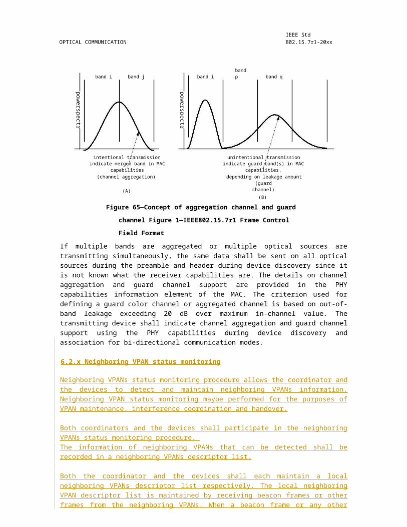
IEEE Std 802.15.7r1-20xx IEEE STANDARD FOR SHORT-RANGE WIRELESS
A Short Address field value equal to 0xfffe shall indicate that the device has been successfully associated with a VPAN, but has not been allocated a short address. In this case, the device shall communicate on the VPAN using only its 64-bit extended address.
6.7.2.3 Association Status field
The Association Status field shall contain one of the nonreserved values listed in Table 13.
Table 13—Valid values of the Association Status field
Association status Description
0x00 Association successful.
0x01 VPAN at capacity.
0x02 VPAN access denied.
0x03–0x7f Reserved.
0x80–0xff Reserved for MAC primitive enumeration values.
6.7.2.4 Capability negotiation response field
The capability negotiation response field describes if and where (device and/or coordinator) color stabilization is performed. All allowed settings are shown in Table 14.
Table 14—Capability negotiation response field
Bits: 0–1 Bits: 2–7
00: No color stabilization
01: Color-stabilization information to be sent fromdevice to coordinator upon reception of CVD frames
10: Color-stabilization information to be sent from Reservedcoordinator to device upon reception of CVD frames
11: Color-stabilization information to be sent fromdevice to coordinator and from coordinator to devicewhen either receives CVD frames
6.7.3 Disassociation notification command
The VLC coordinator or an associated device may send the disassociate notification command.
All devices shall implement this command.
The disassociation notification command shall be formatted as illustrated in Figure 124.
180 Copyright © 20xx IEEE. All rights reserved.

OPTICAL COMMUNICATION IEEE Std 802.15.7r1-20xx
Octets: (see 6.4.6.4) 1 1
MHR fields Command Frame Identifier Disassociation reason(as defined in Table 12)
Figure 124—Disassociation notification command format
6.7.3.1 MHR fields
The Destination Addressing Mode subfield of the frame control field shall be set according to the addressing mode specified by the corresponding primitive. The Source Addressing Mode subfield shall be set to three (i.e., 64-bit extended addressing).
The frame pending subfield of the frame control field shall be set to zero and ignored upon reception, and the Acknowledgment Request subfield shall be set to one.
The VPAN ID Compression subfield of the frame control field shall be set to one. In accordance with this value of the VPAN ID Compression subfield, the Destination VPAN Identifier field shall contain the value of macVPANId, while the Source VPAN Identifier field shall be omitted. If the coordinator wants an associated device to leave the VPAN, then the Destination Address field shall contain the address of the device being removed from the VPAN. If an associated device wants to leave the VPAN, then the Destination Address field shall contain the value of either macCoordShortAddress, if the Destination Addressing Mode subfield is equal to two, or macCoordExtendedAddress, if the Destination Addressing Mode subfield is equal to three. The Source Address field shall contain the value of aExtendedAddress.
6.7.3.2 Disassociation Reason field
The Disassociation Reason field shall contain one of the nonreserved values listed in Table 15.
Table 15—Valid disassociation reason codes
Disassociate reason Description
0x00 Reserved.
0x01 The coordinator wishes the device to leave the VPAN.
0x02 The device wishes to leave the VPAN.
0x03 Device cannot support communications for the requesteddimming value.
0x04f–0x7f Reserved.
0x80–0xff Reserved for MAC primitive enumeration values.
6.7.4 Data request command
The data request command is sent by a device to request data from the coordinator.
There are three cases for which this command is sent. On a beacon -enabled VPAN, this command shall be sent by a device when macAutoRequest is equal to TRUE and a beacon frame indicating that data are pending for that device is received from its coordinator. The coordinator indicates pending data in its beacon
Copyright © 2011 IEEE. All rights reserved. 181

IEEE Std 802.15.7r1-20xx IEEE STANDARD FOR SHORT-RANGE WIRELESS
frame by adding the address of the recipient of the data to the Address List field. This command shall also be sent when instructed to do so by the next higher layer on reception of the MLME-POLL.request primitive. In addition, a device may send this command to the coordinator macResponseWaitTime optical clocks after the acknowledgment to an association request command.
All devices shall be capable of transmitting this command, although a device is not required to be capable of receiving it.
The data request command shall be formatted as illustrated in Figure 125.
Octets: (see 6.4.6.4) 1
MHR fields Command Frame Identifier(as defined in Table 12)
Figure 125—Data request command format
If the data request command is being sent in response to the receipt of a beacon frame indicating that data are pending for that device, the Destination Addressing Mode subfield of the frame control field may be set to zero (i.e., destination addressing information not present) if the beacon frame indicated in its Superframe Specification field (see 6.4.6.1.2) that it originated from the coordinator (see 6.4.1.1.6) or set otherwise according to the coordinator to which the data request command is directed. If the destination addressing information is to be included, the Destination Addressing Mode subfield shall be set according to the value of macCoordShortAddress. If macCoordShortAddress is equal to 0xfffe, extended addressing shall be used: the Destination Addressing Mode subfield shall be set to three, and the Destination Address field shall contain the value of macCoordExtendedAddress. Otherwise, short addressing shall be used: the Destination Addressing Mode subfield shall be set to two, and the Destination Address field shall contain the value of macCoordShortAddress.
If the data request command is being sent in response to the receipt of a beacon frame indicating that data are pending for that device, the Source Addressing Mode subfield shall be set according to the addressing mode used for the pending address. If the Source Addressing Mode subfield is set to two, short addressing shall be used: the Source Address field shall contain the value of macShortAddress. Otherwise, extended addressing shall be used: the Source Addressing Mode subfield shall be set to three, and the Source Address field shall contain the value of aExtendedAddress.
If the data request command is triggered by the reception of an MLME-POLL.request primitive from the next higher layer, then the destination addressing information shall be the same as that contained in the primitive. The Source Addressing Mode subfield shall be set according to the value of macShortAddress. If macShortAddress is less than 0xfffe, short addressing shall be used. Extended addressing shall be used otherwise.
If the data request command is being sent following the acknowledgment to an association request command frame, the Destination Addressing Mode subfield of the frame control field shall be set according to the coordinator to which the data request command is directed. If macCoordShortAddress is equal to 0xfffe, extended addressing shall be used. Short addressing shall be used otherwise. The Source Addressing Mode subfield shall be set to use extended addressing.
If the Destination Addressing Mode subfield is set to zero (i.e., destination addressing information not present), the VPAN ID Compression subfield of the frame control field shall be set to zero and the source VPAN identifier shall contain the value of macVPANId. Otherwise, the VPAN ID Compression subfield shall be set to one. In this case and in accordance with the VPAN ID Compression subfield, the Destination
182 Copyright © 20xx IEEE. All rights reserved.

OPTICAL COMMUNICATION IEEE Std 802.15.7r1-20xx
VPAN Identifier field shall contain the value of macVPANId, while the Source VPAN Identifier field shall be omitted.
The frame pending subfield of the frame control field shall be set to zero and ignored upon reception, and the Acknowledgment Request subfield shall be set to one.
6.7.5 VPAN ID conflict notification command
The VPAN ID conflict notification command is sent by a device to the coordinator when a VPAN identifier conflict is detected.
All devices shall be capable of transmitting this command, although a device is not required to be capable of receiving it.
The VPAN ID conflict notification command shall be formatted as illustrated in Figure 126.
Octets: (see 6.4.6.4) 1
MHR fields Command Frame Identifier(as defined in Table 12)
Figure 126—VPAN ID conflict notification command format
The Destination Addressing Mode and Source Addressing Mode subfields of the frame control field shall both be set to three (i.e., 64-bit extended addressing).
The frame pending subfield of the frame control field shall be set to zero and ignored upon reception, and the Acknowledgment Request subfield shall be set to one.
The VPAN ID Compression subfield of the frame control field shall be set to one. In accordance with this value of the VPAN ID Compression subfield, the Destination VPAN Identifier field shall contain the value of macVPANId, while the Source VPAN Identifier field shall be omitted. The Destination Address field shall contain the value of macCoordExtendedAddress. The Source Address field shall contain the value of aExtendedAddress.
6.7.6 Beacon request command
The beacon request command is used by a device to locate all coordinators within its operating space during an active scan.
This command is optional for a device.
The beacon request command shall be formatted as illustrated in Figure 127.
Octets: 7 1
MHR fields Command Frame Identifier(as defined in Table 12)
Figure 127—Beacon request command format
Copyright © 2011 IEEE. All rights reserved. 183

IEEE Std 802.15.7r1-20xx IEEE STANDARD FOR SHORT-RANGE WIRELESS
The Destination Addressing Mode subfield of the frame control field shall be set to two (i.e., 16-bit short addressing), and the Source Addressing Mode subfield shall be set to zero (i.e., source addressing information not present).
The frame pending subfield of the frame control field shall be set to zero and ignored upon reception. The Acknowledgment Request subfield and Security Enabled subfield shall also be set to zero.
The Destination VPAN Identifier field shall contain the broadcast VPAN identifier (i.e., 0xffff). The Destination Address field shall contain the broadcast short address (i.e., 0xffff).
6.7.7 Coordinator realignment command
The coordinator realignment command is sent by the coordinator or a coordinator when any of its VPAN configuration attributes change due to the receipt of an MLME-START.request primitive.
If this command is sent when any VPAN configuration attributes (i.e., VPAN identifier, short address, or logical channel) change, it is broadcast to the VPAN.
All devices shall be capable of receiving this command, although a device is not required to be capable of transmitting it.
The coordinator realignment command shall be formatted as illustrated in Figure 128.
Octets: 17/18/23/24 1 2 2 1 2
MHR Command VPAN Coordinator Logical Shortfields Frame Identifier Identifier Short Channel Address
(as defined in AddressTable 12)
Figure 128—Coordinator realignment command format
6.7.7.1 MHR fields
The Destination Addressing Mode subfield of the frame control field shall be set to two (e.g., 16-bit short addressing) if it is to be broadcast to the VPAN. The Source Addressing Mode subfield of the frame control field shall be set to three (e.g., 64-bit extended addressing).
The frame pending subfield of the frame control field shall be set to zero and ignored upon reception.
The Acknowledgment Request subfield of the frame control field shall be set to zero if the command is to be broadcast to the VPAN.
The Destination VPAN Identifier field shall contain the broadcast VPAN identifier (e.g., 0xffff). The Destination Address field shall contain the broadcast short address (e.g., 0xffff). The Source VPAN Identifier field shall contain the value of macVPANId, and the Source Address field shall contain the value of aExtendedAddress.
6.7.7.2 VPAN Identifier field
The VPAN Identifier field shall contain the VPAN identifier that the coordinator intends to use for all future communications.
184 Copyright © 20xx IEEE. All rights reserved.
OPTICAL COMMUNICATION IEEE Std 802.15.7r1-20xx
6.7.7.3 Coordinator Short Address field
The Coordinator Short Address field shall contain the value of macShortAddress.
6.7.7.4 Logical Channel field
The Logical Channel field shall contain the logical channel that the coordinator intends to use for all future communications.
6.7.7.5 Short Address field
If the coordinator realignment command is broadcast to the VPAN, the Short Address field shall be set to 0xffff and ignored on reception.
6.7.8 GTS request command
The GTS request command is used by an associated device that is requesting the allocation of a new GTS or the deallocation of an existing GTS from the coordinator. Only devices that have a 16-bit short address less than 0xfffe shall send this command.
This command is optional.
The GTS request command shall be formatted as illustrated in Figure 129.
Octets: 7 1 1
MHR fields Command Frame Identifier GTS Characteristics(as defined in Table 12)
Figure 129—GTS request command format
6.7.8.1 MHR fields
The Destination Addressing Mode subfield of the frame control field shall be set to zero (e.g., destination addressing information not present), and the Source Addressing Mode subfield shall be set to two (e.g., 16-bit short addressing).
The frame pending subfield of the frame control field shall be set to zero and ignored upon reception, and the Acknowledgment Request subfield shall be set to one.
The Source VPAN Identifier field shall contain the value of macVPANId, and the Source Address field shall contain the value of macShortAddress.
6.7.8.2 GTS Characteristics field
The GTS Characteristics field shall be formatted as illustrated in Figure 130.
The GTS Length subfield shall contain the number of superframe slots being requested for the GTS.
The GTS Direction subfield shall be set to one if the GTS is to be a receive-only GTS. Conversely, this subfield shall be set to zero if the GTS is to be a transmit-only GTS. GTS direction is defined relative to the direction of data frame transmissions by the device.
Copyright © 2011 IEEE. All rights reserved. 185

IEEE Std 802.15.7r1-20xx IEEE STANDARD FOR SHORT-RANGE WIRELESS
Bits: 0–3 4 5 6–7
GTS Length GTS Direction Characteristics Type Reserved
Figure 130—GTS Characteristics field format
The Characteristics Type subfield shall be set to one if the characteristics refers to a GTS allocation or zero if the characteristics refers to a GTS deallocation.
6.7.9 Blinking notification command
The blinking notification command (see Figure 131) is sent by a coordinator when the device is no longer responding. A reason for this might be the misalignment between the device TX and the coordinator RX (limited FOV of receiver, low device TX power, mobility of the device, etc.). In such cases, the device can change the visibility indication from continuous visibility for point-and-shoot to blinking indication. The device can then change from point-and-shoot mode to blinking mode in order to indicate to the user that the uplink to the coordinator is disconnected. This indication can be applied to both P2MP and P2P modes of operation.
Octets: 7 1 1
MHR fields Command Frame Identifier Blinking frequency(see Table 12)
Figure 131—Blinking notification command
The blinking notification bit shall be set when the MAC PIB attribute, macUseBlinkingNotification and macBlinkingNotificationFrequency, as defined in Table 62 indicates the blinking notification usage.
To support the blinking notification, the frequency shall be chosen from the phyBlinkingNotificationFrequency PHY PIB attribute as shown in Table 125, using the MLME-SET.request and PLME-SET.request primitives.
This feature can help to align the link and is only intended for mobile devices.
6.7.9.1 Blinking frequency
The frequency subfield shall contain the frequency for blinking (see Figure 132).
Bits: 0–3 4–7
Frequency Reserved
Figure 132—Blinking frequency field format
6.7.10 Dimming notification command
The DME indicates the dimming level to the MAC using the MAC PIB attribute, macDim, as defined in Table 62. The dimming notification command is used to communicate the dimming level set by the macDim PIB attribute to the receiver. The dimming notification command (see Figure 133) shall be sent at the lowest
186 Copyright © 20xx IEEE. All rights reserved.
OPTICAL COMMUNICATION IEEE Std 802.15.7r1-20xx
data rate corresponding to the currently negotiated optical clock rate. The symbol shape information for VPPM is derived using the algorithm of Figure 176 after the dimming level is obtained.
Octets: 7 1 2 2
MHR fields Command frame identifier Dimming level Dimmer adaptation timer(see Table 12) (see 6.2.14.8)
Figure 133—Dimming notification command
The dimming level is two bytes long and contains a value between 0 and 1000, where 0 represents 0% visibility and 1000 represents 100% visibility. The dimming levels are defined with a resolution of 0.1%. The dimmer adaptation timer provides a resolution of 0–16383 MAC clock cycles. The dimming notification command transmits the dimmer level from the TX to the RX along with the dimmer adaptation timer information. VPPM by default uses only 50% duty cycle, so if dimming is supported using VPPM as in 9.5.2.3, the VPPM pulse shape is obtained using the dimmer notification command in conjunction with the algorithm shown in Figure 176. Before dimming is supported using VPPM, the dimming notification command needs to be sent by the MAC to the receiver.
6.7.11 Fast link recovery command
Fast link recovery command is used for the device or coordinator to send the fast link recovery (FLR) signal and the fast link recovery response (FLR RSP), to help the link recovery.
Fast link recovery signal and response use the fast link recovery command format. The fast link recovery command shall be formatted as illustrated in Figure 134.
Octets:1 1(as defined in 6.4.6.4)
MHR fields Command Frame Identifier FLR field(as defined in Table 12)
FLR field explanation
Bit 0: ‘0’ indicating it is FLR signal, ‘1’ indicat-ing it is FLR RSP
Bits 1–3: index of FLR signal direction, if bit 0is ‘0’. received FLR signal direction index if bit 0
is ‘1’.
Bits 4–7: reserved
Figure 134—Fast link recovery command
The FLR signal and the FLR response (RSP) are differentiated by the first bit (bit 0) of the FLR field in the fast link recovery command frame. The device can indicate the index of FLR signal direction by using bits 1 to 3 of the FLR field in the command frame. If the device receives the FLR signal and needs to send FLR
Copyright © 2011 IEEE. All rights reserved. 187

IEEE Std 802.15.7r1-20xx IEEE STANDARD FOR SHORT-RANGE WIRELESS
RSP, it repeats the received FLR signal direction index by using bits 1 to 3 of the FLR field in the command frame. If the device is uni-direction, it uses ‘000’ as the index of the direction.
The usage of the FLR is presented in 6.2.9.
6.7.12 Mobility notification command
The mobility notification command is shown in Figure 135. The concept of VLC cell mobility is defined in 6.2.11.
Octets: 7 1 variable
MHR fields Command Frame Identifier cellSearchQuality(Table 12) (see 6.2.11.3)
Figure 135—Mobility notification command
The results from the cell search are provided in the mobility notification command as shown in Figure 135. The WQI values (in octets) obtained for the current channel during the cell search procedure defined in 6.2.11.3 shall be included in the command frame. The number of octets sent shall be equal to cellSearchLength, as defined in 6.2.11.3.
6.7.13 GTS response command
The optional GTS.response primitive is generated in response to a GTS.request primitive. When used, the GTS response command shall be formatted as illustrated in Figure 136.
Octets: 7 1 1 1
MHR fields Command Frame Identifier GTS characteristics GTS Starting Slotas defined in Table 12) (see 6.4.6.1.5)
Figure 136—GTS response command format
6.7.13.1 MHR fields
The Destination Addressing Mode subfield of the frame control field shall be set to zero (e.g., destination addressing information not present), and the Source Addressing Mode subfield shall be set to two (e.g., 16-bit short addressing).
The frame pending subfield of the frame control field shall be set to zero and ignored upon reception, and the Acknowledgment Request subfield shall be set to one.
The Source VPAN Identifier field shall contain the value of macVPANId, and the Source Address field shall contain the value of macShortAddress.
6.7.13.2 GTS Characteristics field
The GTS Characteristics field shall be formatted as illustrated in Figure 137.
188 Copyright © 20xx IEEE. All rights reserved.
OPTICAL COMMUNICATION IEEE Std 802.15.7r1-20xx
Bits: 0–3 4 5 6–7
GTS Length GTS Direction Characteristics Type Reserved
Figure 137—GTS Characteristics field format
The GTS Length subfield shall contain the number of superframe slots being requested for the GTS.
The GTS Direction subfield shall be set to one if the GTS is to be a receive-only GTS. Conversely, this subfield shall be set to zero if the GTS is to be a transmit-only GTS. GTS direction is defined relative to the direction of data frame transmissions by the device.
The Characteristics Type subfield shall be set to one if the characteristics refers to a GTS allocation or zero if the characteristics refers to a GTS deallocation.
6.7.14 Clock rate change notification command
The command format for the clock rate change notification is as shown in Figure 138. This clock rate change notification is sent at the current clock rate negotiated between the devices. All future transmissions from the current device to the receiving device will occur at this new clock rate.
Octets: 7 1 1
MHR fields Command Frame Identifier (as New clock rate for futuredefined in Table 12) TX
Figure 138—Clock rate change notification format
The modulation and coding scheme (MCS) ID from Table 94 shall be used to indicate the optical clock rate. Any MCS ID corresponding to the chosen future clock rate can be used. The 6 LSBs shall be set to the MCS ID corresponding to the future clock rate. The other bits are set to 0 and reserved for future use.
6.7.15 Multiple channel assignment command
Octets: 7 1 1
MHR fields Command Frame Identifier (as Multiple Channelsdefined in Table 12)
Figure 139—Multiple channel assignment command format
Multiple channels should be used in the VLC system when time slot resources are not enough to cover all the currents users. These channels should be assigned based on the band-plan in Table 87. Refer to Table 4 for the contents of the Multiple Channels field.
Copyright © 2011 IEEE. All rights reserved. 189
IEEE Std 802.15.7r1-20xx IEEE STANDARD FOR SHORT-RANGE WIRELESS
6.7.16 Color stabilization timer notification command
The color stabilization timer notification command shall be formatted as illustrated in Figure 140. This command is used to inform a device or coordinator about the minimum time between two color-stabilization updates (upon reception of CVD frames).
Octets: 7 1 2 4
MHR fieldsCommand frame identifier
Short address Color stabilization timer(see Table 12)
Figure 140—Color stabilization timer notification command format
The color stabilization timer field has the same format as the macColorStabilizationTimer (see Table 62).
6.7.17 Color stabilization information command
The color stabilization information command shall be formatted as illustrated in Figure 141. This command is used for relaying the color-stabilization updates (upon reception of CVD frames) back to the pertinent CSK transmitter (see Figure 183).
Octets: 7 1 2Color stabilization information
2 2 2
MHR fieldsCommand frame identifier
Short address band i band j band k(see Table 12)
Figure 141—Color stabilization information command format
The color stabilization information per band is 2 octets long and is used by the color-stabilization module (see Figure 184). It consists of the received signal levels in each of the three CSK bands. Two octets are used for each of the bands. A linear scale is used for each band, where the highest value corresponds to the maximum receive signal and the lowest value to the minimum receive signal. These fields are sent LSB first.
6.7.18 CVD disable command
Octets: 7 1 1
MHR fields Command frame identifier (see Table 12) CVD disable
Figure 142—CVD disable command format
The CVD frame can be transmitted depending on bi-directional, multicasting, and broadcasting capabilities. A device shall not transmit a CVD frame after the device has received a frame from an associated device that has the “CVD usage option” bit set to ‘0’ as defined in Table 16. A device may resume sending CVD frames after it has received a frame from associated devices that have the “CVD usage option” bit set to ‘1’. When the coordinator transmits and receives data with a device, if another device transmits an in-band CVD frame,
190 Copyright © 20xx IEEE. All rights reserved.
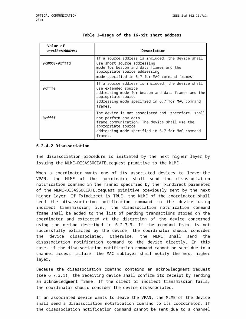
OPTICAL COMMUNICATION IEEE Std 802.15.7r1-20xx
interference may occur in the link between the coordinator and device. Out-of-band idle patterns may be used to maintain visibility when interference is seen in devices due to use of the CVD frame. In this case, the coordinator may indicate the transmission of “CVD usage option” with the CVD usage option bit set to ‘0’. The CVD frame should be used prudently so as to cause minimal interference and prolong battery life. In many cases, a light source is used for illumination, which takes precedence over the use for communication.
The CVD usage option subfield is 1 bit in length and shall be set to ‘1’ if the device is sending a CVD frame. This subfield shall be set to ‘0’ otherwise.
Table 16—CVD disable field
Command frameBit Usage/Descriptionpayload
CVD usage option b0 logic 1 indicates that the device shall transmit the CVD frame
logic 0 indicates that the device shall not transmit the CVD frameand may use out-of-band idle patterns if visibility needs to bemaintained
b1–b7 Reserved
6.7.19 Information element command
The format of an individual information element (IE) is shown in Figure 143. The first octet is the Element ID and the second octet is the Length (Ln) of the payload of the IE in octets. The following Ln octets are the payload for the IE. Unless otherwise specified, these elements may appear in any order in the frames that are allowed to include more than one of these elements.
Octets: 1 1 Ln
Element ID Length (=Ln) IE payload
Figure 143—Information element format
The information elements defined in this standard are listed in Table 17.
Table 17—Information elements
Element IDElement Subclausehex value
0x01 Capabilities 6.7.19.1
0x02Wavelength quality
6.7.19.2indication
When the information elements are used, they shall be added at the end of command frame format. Multiple information elements can be part of a single command frame. IEs can be added to any command frame.
Copyright © 2011 IEEE. All rights reserved. 191
IEEE Std 802.15.7r1-20xx IEEE STANDARD FOR SHORT-RANGE WIRELESS
6.7.19.1 Capabilities IE
The capabilities IE is used to convey device MAC and PHY capabilities to peer devices. The capabilities IE, as shown in Figure 144, consists of two fields: the capability information field, refer to Table 18, which indicates general capabilities of the device; and the aggregation bitmap field, which is specified in Figure 144.
Octets: 8 variable: 8n variable: 8n
Capability Information Field Aggregation bitmap field Guard bitmap field
Figure 144—Capabilities IE
6.7.19.1.1 Capability information field
The capability information field is illustrated in Table 18.
Table 18—Capability information field
BitFunctionposition
0 Power source
1–2 Battery information
3 Security capability
4 Coordinator capability
MAC layer5 Traffic support
capabilities 6–8 Topology support
9–10 Device type
11 Beacon support
12 Dimming support
13 Continuous visibility transmission (for infrastructure)
14 CVD support
15–23 Reserved
192 Copyright © 20xx IEEE. All rights reserved.
OPTICAL COMMUNICATION IEEE Std 802.15.7r1-20xx
Table 18—Capability information field (continued)
BitFunctionposition
24 PHY I support
25 PHY II support
26 PHY III supportPHY layer
27–28 Color stabilization capabilitycapabilities
29–31 Max supported TX clock
32–34 Max supported RX clock
35 Explicit clock notification request
36 CCA support
37–39 Reserved
Physical40–42 Number of optical sources
43–45 Multiple direction supportdevicecapabilities
46–55 Number of cells supported (n)
Band 56–63 Bands used for PHY III (any 3 bits of the bits set to 1 can be used)capabilities
The power source subfield is 1 bit in length and shall be set to one if the device is receiving power from the alternating current mains. Otherwise, the power source subfield shall be set to zero.
The battery information subfield, shown in Table 19, is set to reserved (11) if the power source is set to 1.
Table 19—Battery Indication
Bits (b2 b1) Battery indication
00 Unknown
11 < 50% (low battery)
10 50% (sufficient battery)
11 Reserved
The security capability subfield is 1 bit in length and shall be set to one if the device is capable of sending and receiving cryptographically protected MAC frames; otherwise, it shall be set to zero.
The coordinator capability subfield is 1 bit in length and shall be set to 1 if the device is capable of functioning as a coordinator; otherwise, it shall be set to zero.
The traffic support capability subfield is 1 bit in length. It shall be set to 0 if the device is only capable of broadcasting (unidirectional) communication. Otherwise, it shall be set to 1.
Copyright © 2011 IEEE. All rights reserved. 193
IEEE Std 802.15.7r1-20xx IEEE STANDARD FOR SHORT-RANGE WIRELESS
The topology support capability subfield can support multiple topologies via the bit maps of Table 19.
Table 20—Topology support capability
Bits (b8 b7 b6) Topology indication
b8 P2MP
b7 P2P
b6 Broadcast
The device-type capability subfield is set according to Table 21. This information is provided to assist upper layers.
Table 21—Device-type capability
Bits (b10 b9) Device capability
00 Infrastructure
01 Mobile
10 Vehicle
11 Unknown/reserved
The beacon support capability subfield is 1 bit in length. It shall be set to 1 if the device is capable of sending beacons. Otherwise, it shall be set to 0.
The dimming support in MAC capability subfield is 1 bit in length. It shall be set to 1 if the device is capable of supporting dimming in the MAC using duty cycling and idle patterns. Otherwise, it shall be set to 0. A device shall honor all dimming requests. If the dimming support bit is not set then the device shall not attempt to communicate when a dimming request is received and shall comply with the dimming request even if the device must disassociate from the network as discussed in 6.2.4.2. Even if the device supports dimming but is unable to communicate during dimming, it shall set the macDimDataFailureIndication MAC PIB attribute as mentioned in Table 62, but shall still comply with the dimming request at the expense of loss of communication.
The continuous visibility transmission subfield is one bit in length. It shall be set to 1 if the device will be continuously transmitting to maintain illumination. Otherwise, it shall be to 0.
The CVD support subfield is 1 bit in length. It shall be set to 1 if the device is capable of transmitting various colors; otherwise, it shall be set to 0.
The PHY I support subfield is 1 bit in length. It shall be set to 1 if the device supports PHY I.
The PHY II support subfield is 1 bit in length. It shall be set to 1 if the device supports PHY II.
The PHY III support subfield is 1 bit in length. It shall be set to 1 if the device supports PHY III.
194 Copyright © 20xx IEEE. All rights reserved.
OPTICAL COMMUNICATION IEEE Std 802.15.7r1-20xx
The color-stabilization capability subfield describes if and where (device and/or coordinator) color stabilization is performed. All allowed settings are shown in Table 22.
Table 22—Color-stabilization capability
Bits (b28 b27) Color-stabilization scheme
00 No color stabilization
1 Color-stabilization information to be sent from device to coordinator upon reception of CVD frames
10 Color-stabilization information to be sent from coordinator to device upon reception of CVD frames
11 Color-stabilization information to be sent from device to coordinator and from coordinator to device when either receives CVD frames
The max supported TX clock subfield and max RX clock subfields follow the usage as indicated in Table 23. Support for 200 kHz is mandatory for PHY I and support of 3.75 MHz is mandatory for PHY II. Support for 12 MHz is mandatory for PHY III and shall be indicated using bits ‘100’ as in Table 23.
Table 23—Maximum supported optical clock frequency
Bits (b31 b30 b29) Description
000 200 kHz
001 400 kHz
010 3.75 MHz
011 7.5 MHz
100 15 MHz
101 30 MHz
110 60 MHz
111 120 MHz
The explicit clock notification subfield is 1 bit in length. The subfield shall be set to 1 if the receiving device needs an explicit clock change notification from the transmitter before any change of clock frequency.
If CCA is supported, then the CCA Support bit is set to 1; otherwise, the bit is set to 0.
The number of optical sources subfield indicates the number of optical sources in the transmitter of the device that have distinct frequency responses.
The multiple direction support subfield indicates the number of distinct directions supported by the device transmitter supported by the multiple optical sources. This is used for fast link recovery as defined in 6.7.11.
The number of cells n indicates the maximum number of cells supported in the device. The number of cells supported shall not be more than 1023.
Copyright © 2011 IEEE. All rights reserved. 195
IEEE Std 802.15.7r1-20xx IEEE STANDARD FOR SHORT-RANGE WIRELESS
In regards to the bands used for PHY III, bit 7 is reserved and bits 0–6 map to the bits corresponding to the bandplan. Only 3 bits shall be set to indicate PHY III usage. If the device supports more colors and wants to change the PHY III usage, it needs to send the capabilities information again with the new bitmap.
6.7.19.1.2 Aggregation and guard channel
The aggregation and guard channels are used to support any visible light optical source for VLC that may have variable spectral widths and center frequencies. The aggregation and guard bitmap for a single optical source type is as shown in Figure 145. The bit map is variable in length. The length of the aggregation and guard bit maps are ‘n’ octets each, where ‘n’ is the number of optical source types. The aggregation and guard channel bit usage are defined by an 8-bit bitmap for every optical source type supported by the transmitter of the device. The 8- bit bitmap is indexed by the bandplan identification number. The bit position ‘m’ is set to a ‘1’ for band 'm' if that band is used by the optical source. The reserved bit in Figure 145 shall be set to 0.
Figure 145—Aggregation and guard bitmap per optical source type
For example,
if band 1 and band 2 need to be aggregated [assuming a blue light-emitting diode (LED)], the aggregation bit-map is indicated as 0110000 and the guard bit-map is indicated as 0000000.
if band 1 is being used but there is leakage in bands 3, 4, 5 (assuming a white LED, which is realized via a blue LED with yellow phosphor), the aggregation bit map is indicated as 0100000 and the guard bit-map is indicated as 0001110.
6.7.19.2 Wavelength quality indication (WQI) IE
WQI is communicated to another device using the WQI Information Element. The WQI value to be sent in the Information Element may be an average value across a number of packets, and WQI value sets for a number of band plan ID's can be reported using the WQI information element as shown in Table 24. The wavelength quality indication IE is 7 octets in length and the WQI information is provided for all band plan IDs. If a band plan ID is not supported, WQI of 0 shall be reported.
196 Copyright © 20xx IEEE. All rights reserved.
OPTICAL COMMUNICATION IEEE Std 802.15.7r1-20xx
Table 24—Wavelength quality indication IE
Band plan code WQI value
0x00 0x00 to 0xff
0x01 0x00 to 0xff
0x02 0x00 to 0xff
0x03 0x00 to 0xff
0x04 0x00 to 0xff
0x05 0x00 to 0xff
0x06 0x00 to 0xff
7. MAC sublayer service specification
7.1 Overview
The MAC sublayer provides an interface between the SSCS, DME and the PHY. The MAC sublayer conceptually includes a management entity called the MLME. This entity provides the service interfaces through which layer management functions may be invoked. The MLME is also responsible for maintaining a database of managed objects pertaining to the MAC sublayer. This database is referred to as the MAC sublayer PIB.
Figure 146 depicts the components and interfaces of the MAC sublayer.
Figure 146—MAC sublayer reference model
The MAC sublayer provides the following two services, accessed through two SAPs:
a) The MAC data service, accessed through the MAC common part sublayer (MCPS) data SAP (MCPS-SAP), and
b) The MAC management service, accessed through the MLME-SAP.
These two services provide the interface between the SSCS and the PHY, via the PD-SAP and PLME-SAP interfaces (see Clause 10). In addition to these external interfaces, an implicit interface also exists between the MLME and the MCPS that allows the MLME to use the MAC data service.
Copyright © 2011 IEEE. All rights reserved. 197
IEEE Std 802.15.7r1-20xx IEEE STANDARD FOR SHORT-RANGE WIRELESS
7.2 MAC data service
The MCPS-SAP supports the transport of SSCS protocol data units (SPDUs) between peer SSCS entities. Table 25 lists the primitives supported by the MCPS-SAP. These primitives are discussed in the subclauses referenced in this table.
Table 25—MCPS-SAP primitives
MCPS-SAP primitive Request Confirm Indication
MCPS-DATA 7.2.1 7.2.2 7.2.3
MCPS-PURGE 7.2.4 7.2.5 —
7.2.1 MCPS-DATA.request
The MCPS-DATA.request primitive requests the transfer of a data SPDU (i.e., MSDU) from a local SSCS entity to a single peer SSCS entity. In the packed mode, multiple MSDU are passed via a local SSCS entity to a single peer SSCS entity.
The semantics of the MCPS-DATA.request primitive are as follows:
MCPS-DATA.request (SrcAddrMode,DstAddrMode,DstVPANId,DstAddr,MsduLength,Msdu,MsduHandle,TxOptions,SecurityLevel,KeyIdMode,KeySource,KeyIndex,DataRate,BurstMode,ColorReceived,ColorNotReceived)
Table 26 specifies the parameters for the MCPS-DATA.request primitive.
7.2.1.1 Appropriate usage
The MCPS-DATA.request primitive is generated by a local SSCS entity when a data SPDU (i.e., MSDU) is to be transferred to a peer SSCS entity.
198 Copyright © 20xx IEEE. All rights reserved.

OPTICAL COMMUNICATION IEEE Std 802.15.7r1-20xx
Table 26—MCPS-DATA.request parameters
Name Type Valid range Description
SrcAddrMode Integer 0x00–0x03 The source addressing mode for this primitive andsubsequent MPDU. This value can take one of thefollowing values:0x00 = No address (addressing fields omitted, asdefined in 6.4.1.1.7).0x01 = Reserved.0x02 = 16-bit short address.0x03 = 64-bit extended address.
DstAddrMode Integer 0x00–0x03 The destination addressing mode for this primitiveand subsequent MPDU. This value can take one ofthe following values:
0x00 = No address (addressing fields omitted, asdefined in 6.4.1.1.6).0x01 = No address field (broadcast only mode withno address fields present).0x02 = 16-bit short address.0x03 = 64-bit extended address.
DstVPANId Integer 0x0000–0xffff The 16-bit VPAN identifier of the entity to whichthe MSDU is being transferred.
DstAddr Device As specified by the The individual device address of the entity to whichaddress DstAddrMode parameter the MSDU is being transferred.
MsduLength Integer aMaxMACPayloadSize The number of octets contained in the MSDU to betransmitted by the MAC sublayer entity.
Msdu Set of octets — The set of octets forming the MSDU to betransmitted by the MAC sublayer entity.
MsduHandle Integer 0x00–0xff The handle associated with the MSDU to betransmitted by the MAC sublayer entity.
TxOptions Bitmap 3-bit field The 3 bits (b0, b1, b2) indicate the transmissionoptions for this MSDU.
For b0, 1 = acknowledged transmission,0 = unacknowledged transmission.For b1, 1 = GTS transmission, 0 = CAP transmissionfor a beacon-enabled VPAN.For b2, 1 = indirect transmission, 0 = directtransmission.For a non-beacon-enabled VPAN, bit b1 should
always be set to 0.
SecurityLevel Integer 0x00–0x07 The security level to be used (as defined in Table 67in 8.4.2.1).
KeyIdMode Integer 0x00–0x03 The mode used to identify the key to be used (asdefined in Table 68 in 8.4.2.2). This parameter isignored if the SecurityLevel parameter is set to0x00.
KeySource Set of 0, 4, As specified by the The originator of the key to be used (see 8.4.4.1).or 8 octets KeyIdMode parameter This parameter is ignored if the KeyIdMode
parameter is ignored or set to 0x00.
Copyright © 2011 IEEE. All rights reserved. 199
IEEE Std 802.15.7r1-20xx IEEE STANDARD FOR SHORT-RANGE WIRELESS
Table 26—MCPS-DATA.request parameters (continued)
Name Type Valid range Description
KeyIndex Integer 0x01–0xff The index of the key to be used (see 8.4.4.2). Thisparameter is ignored if the KeyIdMode parameter isignored or set to 0x00.
DataRate Enumeration 6-bit field The data rate of the PHY frame to be transmitted bythe PHY entity as shown in Table 94.
BurstMode Boolean TRUE or FALSE The BurstMode bit shall be set TRUE if the burstmode is being used (as discussed in 9.6.1);otherwise, the BurstMode bit shall be set FALSE.
ColorReceived Boolean TRUE or FALSE ColorReceived shall be set as TRUE, when theACK frame is sent and the color function for theACK state indication is used by the CVD frame.
ColorReceived shall be set as FALSE when theACK frame is sent but the color function for theACK state indication is not used by the CVD frame.
ColorNotReceived Boolean TRUE or FALSE ColorNotReceived shall be set as TRUE, when theACK frame is not sent but the color function for thenon-ACK state indication is used by the CVDframe.
ColorNotReceived shall be set as FALSE when theACK frame is not sent and the color function for thenon-ACK state indication is not used by the CVDframe.
7.2.1.2 Effect on receipt
On receipt of the MCPS-DATA.request primitive, the MAC sublayer entity begins the transmission of the supplied MSDU.
The MAC sublayer builds an MPDU to transmit from the supplied arguments. The flags in the SrcAddrMode and DstAddrMode parameters correspond to the addressing subfields in the frame control field, as shown in 6.4.1.1, and are used to construct both the frame control and addressing fields of the MHR. If both the SrcAddrMode and the DstAddrMode parameters are set to 0x00 (i.e., addressing fields omitted), the MAC sublayer will issue the MCPS-DATA.confirm primitive with a status of INVALID_ADDRESS.
The TxOptions parameter indicates how the MAC sublayer data service transmits the supplied MSDU. If the TxOptions parameter specifies that an acknowledged transmission is required, the Acknowledgment Request subfield of the frame control field will be set to one (see 6.2.7.4).
If the TxOptions parameter specifies that a GTS transmission is required, the MAC sublayer will determine whether it has a valid GTS (for GTS usage rules, as defined in 6.2.8.3). If a valid GTS could not be found, the MAC sublayer will issue the MCPS-DATA.confirm primitive with a status of INVALID_GTS. If a valid GTS was found, the MAC sublayer will defer, if necessary, until the GTS. If the TxOptions parameter specifies that a GTS transmission is not required, the MAC sublayer will transmit the MSDU using either slotted random access in the CAP for a beacon-enabled VPAN or unslotted random access for a nonbeacon-enabled VPAN. Specifying a GTS transmission in the TxOptions parameter overrides an indirect transmission request.
200 Copyright © 20xx IEEE. All rights reserved.
OPTICAL COMMUNICATION IEEE Std 802.15.7r1-20xx
If the TxOptions parameter specifies that an indirect transmission is required and this primitive is received by the MAC sublayer of a coordinator, the data frame is sent using indirect transmission, i.e., the data frame is added to the list of pending transactions stored on the coordinator and extracted at the discretion of the device concerned using the method described in 6.2.7.3. Transactions with a broadcast destination address will be transmitted using the mechanism described in 6.4.1.1.4. Transactions with a unicast destination address can then be extracted at the discretion of each device concerned using the method described in 6.2.7.3. If there is no capacity to store the transaction, the MAC sublayer will discard the MSDU and issue the MCPS-DATA.confirm primitive with a status of TRANSACTION_OVERFLOW. If there is capacity to store the transaction, the coordinator will add the information to the list. If the transaction is not handled within macTransactionPersistenceTime, the transaction information will be discarded and the MAC sublayer will issue the MCPS-DATA.confirm primitive with a status of TRANSACTION_ EXPIRED. The transaction handling procedure is described in 6.2.6. If the TxOptions parameter specifies that an indirect transmission is required and if the device receiving this primitive is not a coordinator, the destination address is not present, or the TxOptions parameter also specifies a GTS transmission, the indirect transmission option will be ignored.
If the TxOptions parameter specifies that an indirect transmission is not required, the MAC sublayer will transmit the MSDU using slotted random access either in the CAP for a beacon- enabled VPAN or immediately for a nonbeacon -enabled VPAN. If the TxOptions parameter specifies that a direct transmission is required and the MAC sublayer does not receive an acknowledgment from the recipient after macMaxFrameRetries retransmissions (see 6.2.7.4), it will discard the MSDU and issue the MCPS-DATA.confirm primitive with a status of NO_ACK.
If the SecurityLevel parameter is set to a valid value other than 0x00, indicating that security is required for this frame, the MAC sublayer will set the Security Enabled subfield of the frame control field to one. The MAC sublayer will perform outgoing processing on the frame based on the DstAddr, SecurityLevel, KeyIdMode, KeySource, and KeyIndex parameters, as described in 8.2.1. If any error occurs during outgoing frame processing, the MAC sublayer will discard the frame and issue the MCPS-DATA.confirm primitive with the error status returned by outgoing frame processing.
If the requested transaction is too large to fit in the CAP or GTS, as appropriate, the MAC sublayer shall discard the frame and issue the MCPS-DATA.confirm primitive with a status of FRAME_TOO_LONG.
If the transmission attempts a random access (either slotted or unslotted) and the random access algorithm failed due to adverse conditions on the channel, and the TxOptions parameter specifies that a direct transmission is required, the MAC sublayer will discard the MSDU and issue the MCPS-DATA.confirm primitive with a status of CHANNEL_ACCESS_FAILURE.
If the MAC sublayer receives the request while transmission is prohibited, it shall delay transmission until transmission is permitted.
If the MPDU was successfully transmitted and, if requested, an acknowledgment was received, the MAC sublayer will issue the MCPS-DATA.confirm primitive with a status of SUCCESS.
If any parameter in the MCPS-DATA.request primitive is not supported or is out of range, the MAC sublayer will issue the MCPS-DATA.confirm primitive with a status of INVALID_PARAMETER.
7.2.2 MCPS-DATA.confirm
The MCPS-DATA.confirm primitive reports the results of a request to transfer a data SPDU (MSDU) from a local SSCS entity to a single peer SSCS entity.
Copyright © 2011 IEEE. All rights reserved. 201
IEEE Std 802.15.7r1-20xx IEEE STANDARD FOR SHORT-RANGE WIRELESS
The semantics of the MCPS-DATA.confirm primitive are as follows:
MCPS-DATA.confirm (MsduHandle,status,Timestamp)
Table 27 specifies the parameters for the MCPS-DATA.confirm primitive.
Table 27—MCPS-DATA.confirm parameters
Name Type Valid range Description
MsduHandle Integer 0x00–0xff The handle associated with the MSDUbeing confirmed.
status Enumeration SUCCESS, The status of the last MSDUTRANSACTION_OVERFLOW, transmission.TRANSACTION_EXPIRED,CHANNEL_ACCESS_FAILURE,INVALID_ADDRESS,INVALID_GTS, NO_ACK,COUNTER_ERROR,FRAME_TOO_LONG,UNAVAILABLE_KEY,UNSUPPORTED_SECURITY orINVALID_PARAMETER
Timestamp Integer 0x000000–0xffffff Optional. The time, in optical clocks, atwhich the data were transmitted (see6.2.5.1).
The value of this parameter will beconsidered valid only if the value of thestatus parameter is SUCCESS; if thestatus parameter is not equal toSUCCESS, the value of the Timestampparameter shall not be used for any otherpurpose. The boundary is described bymacTimeStampOffset (as defined inTable 62).
The time stamp is a 24-bit value, andthe precision of this value shall be aminimum of 20 bits, with the lowest4 bits being the least significant.
7.2.2.1 When generated
The MCPS-DATA.confirm primitive is generated by the MAC sublayer entity in response to an MCPS-DATA.request primitive. The MCPS-DATA.confirm primitive returns a status of either SUCCESS, indicating that the request to transmit was successful, or the appropriate error code. The status values are fully described in 7.2.1.2 and subclauses referenced by 7.2.1.2.
202 Copyright © 20xx IEEE. All rights reserved.
OPTICAL COMMUNICATION IEEE Std 802.15.7r1-20xx
7.2.2.2 Appropriate usage
On receipt of the MCPS-DATA.confirm primitive, the SSCS of the initiating device is notified of the result of its request to transmit. If the transmission attempt was successful, the status parameter will be set to SUCCESS. Otherwise, the status parameter will indicate the error.
7.2.3 MCPS-DATA.indication
The MCPS -DATA.indication primitive indicates the transfer of a data SPDU (i.e., MSDU) from the MAC sublayer to the local SSCS entity. In the packed mode, multiple MSDU are passed via a local SSCS entity to a single peer SSCS entity.
The semantics of the MCPS-DATA.indication primitive are as follows:
MCPS-DATA.indication (SrcAddrMode,SrcVPANId,SrcAddr,DstAddrMode,DstVPANId,DstAddr,MsduLength,Msdu,MpduLinkQuality,DSN,Timestamp,SecurityLevel,KeyIdMode,KeySource,KeyIndex,DataRate,BurstMode,ColorReceived,ColorNotReceived)
Table 28 specifies the parameters for the MCPS-DATA.indication primitive.
Table 28—MCPS-DATA.indication parameters
Name Type Valid range Description
SrcAddrMode Integer 0x00–0x03 The source addressing mode for this primitivecorresponding to the received MPDU. This value cantake one of the following values:
0x00 = no address (addressing fields omitted).0x01 = reserved.0x02 = 16-bit short address.0x03 = 64-bit extended address.
SrcVPANId Integer 0x0000–0xffff The 16-bit VPAN identifier of the entity from whichthe MSDU was received.
Copyright © 2011 IEEE. All rights reserved. 203
IEEE Std 802.15.7r1-20xx IEEE STANDARD FOR SHORT-RANGE WIRELESS
Table 28—MCPS-DATA.indication parameters (continued)
Name Type Valid range Description
SrcAddr Device As specified by the The individual device address of the entity from whichaddress SrcAddrMode the MSDU was received.
parameter
DstAddrMode Integer 0x00–0x03 The destination addressing mode for this primitivecorresponding to the received MPDU. This value cantake one of the following values:
0x00 = no address (addressing fields omitted).0x01 = no address field (broadcast only mode with noaddress fields present).0x02 = 16-bit short device address.0x03 = 64-bit extended device address.
DstVPANId Integer 0x0000–0xffff The 16-bit VPAN identifier of the entity to which theMSDU is being transferred.
DstAddr Device As specified by the The individual device address of the entity to whichaddress DstAddrMode the MSDU is being transferred.
parameter
MsduLength Integer aMaxMacPayloadSize The number of octets contained in the MSDU beingindicated by the MAC sublayer entity.
Msdu Set of octets — The set of octets forming the MSDU being indicatedby the MAC sublayer entity.
MpduLinkQuality Integer 0x00–0xff WQI value measured during reception of the MPDU.Lower values represent lower WQI (see 6.7.19.2)
DSN Integer 0x00–0xff The DSN of the received data frame.
Timestamp Integer 0x000000–0xffffff Optional. The time, in optical clocks, at which the datawere received (see 6.2.5.1).
The boundary is described by macTimeStampOffset (asdefined in Table 62).
The time stamp is a 24-bit value, and the precision ofthis value shall be a minimum of 20 bits, with thelowest 4 bits being the least significant.
SecurityLevel Integer 0x00–0x07 The security level purportedly used by the receiveddata frame (as defined in Table 67 in 8.4.2.1).
KeyIdMode Integer 0x00–0x03 The mode used to identify the key purportedly used bythe originator of the received frame (as defined inTable 68 in 8.4.2.2). This parameter is invalid if theSecurityLevel parameter is set to 0x00.
KeySource Set of 0, 4, As specified by the The originator of the key purportedly used by theor 8 octets KeyIdMode parameter originator of the received frame (see 8.4.4.1). This
parameter is invalid if the KeyIdMode parameter isinvalid or set to 0x00.
KeyIndex Integer 0x01–0xff The index of the key purportedly used by theoriginator of the received frame (see 8.4.4.2). Thisparameter is invalid if the KeyIdMode parameter isinvalid or set to 0x00.
204 Copyright © 20xx IEEE. All rights reserved.
OPTICAL COMMUNICATION IEEE Std 802.15.7r1-20xx
Table 28—MCPS-DATA.indication parameters (continued)
Name Type Valid range Description
DataRate Enumeration 6-bit field The data rate of the PHY frame to be transmitted bythe PHY entity as shown in Table 94.
BurstMode Boolean TRUE or FALSE The BurstMode bit shall be set TRUE if the burstmode is being used (as discussed in 9.6.1); otherwise,the BurstMode bit shall be set FALSE.
ColorReceived Boolean TRUE or FALSE ColorReceived shall be set as TRUE, if CVD frame issent when data frame is successfully received.
ColorNotReceived Boolean TRUE or FALSE ColorNotReceived shall be set as TRUE, if CVDframe is sent when data frame is not received.
7.2.3.1 When generated
The MCPS-DATA.indication primitive is generated by the MAC sublayer and issued to the SSCS on receipt of a data frame at the local MAC sublayer entity that passes the appropriate message filtering operations as described in 6.2.7.2.
7.2.3.2 Appropriate usage
On receipt of the MCPS-DATA.indication primitive, the SSCS is notified of the arrival of data at the device.
7.2.4 MCPS-PURGE.request
The MCPS-PURGE.request primitive allows the next higher layer to purge an MSDU from the transaction queue.
This primitive is optional for a device.
The semantics of the MCPS-PURGE.request primitive are as follows:
MCPS-PURGE.request (MsduHandle)
Table 29 specifies the parameters for the MCPS-PURGE.request primitive.
Table 29—MCPS-PURGE.request parameters
Name Type Valid range Description
MsduHandle Integer 0x00–0xff The handle of the MSDU to be purged fromthe transaction queue.
Copyright © 2011 IEEE. All rights reserved. 205
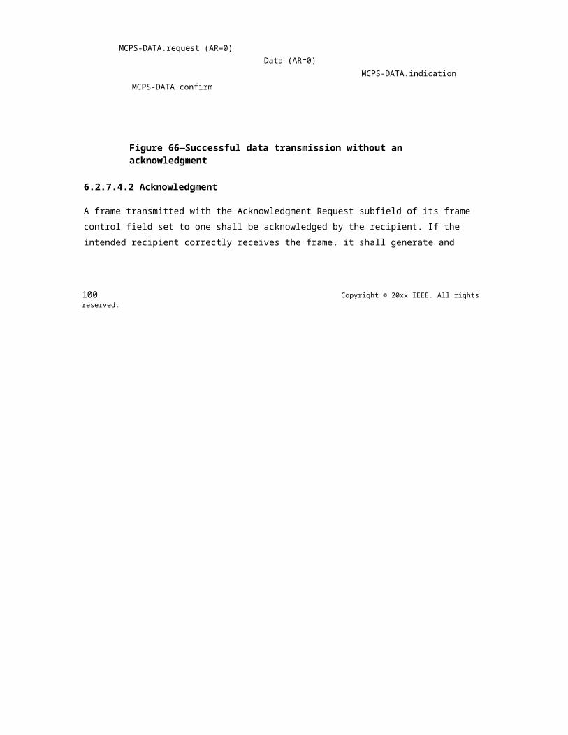
IEEE Std 802.15.7r1-20xx IEEE STANDARD FOR SHORT-RANGE WIRELESS
7.2.4.1 Appropriate usage
The MCPS-PURGE.request primitive is generated by the next higher layer whenever a MSDU is to be purged from the transaction queue.
7.2.4.2 Effect on receipt
On receipt of the MCPS-PURGE.request primitive, the MAC sublayer attempts to find in its transaction queue the MSDU indicated by the MsduHandle parameter. If an MSDU has left the transaction queue, the handle will not be found, and the MSDU can no longer be purged. If an MSDU matching the given handle is found, the MSDU is discarded from the transaction queue, and the MAC sublayer issues the MCPS-PURGE.confirm primitive with a status of SUCCESS. If an MSDU matching the given handle is not found, the MAC sublayer issues the MCPS-PURGE.confirm primitive with a status of INVALID_HANDLE.
7.2.5 MCPS-PURGE.confirm
The MCPS-PURGE.confirm primitive allows the MAC sublayer to notify the next higher layer of the success of its request to purge an MSDU from the transaction queue.
This primitive is optional for a device.
The semantics of the MCPS-PURGE.confirm primitive are as follows:
MCPS-PURGE.confirm (MsduHandle,status)
Table 30 specifies the parameters for the MCPS-PURGE.confirm primitive.
Table 30—MCPS-PURGE.confirm parameters
Name Type Valid range Description
MsduHandle Integer 0x00–0xff The handle of the MSDU requested to bepurge from the transaction queue.
status Enumeration SUCCESS or The status of the request to be purged anINVALID_HANDLE MSDU from the transaction queue.
7.2.5.1 When generated
The MCPS-PURGE.confirm primitive is generated by the MAC sublayer entity in response to an MCPS-PURGE.request primitive. The MCPS-PURGE.confirm primitive returns a status of either SUCCESS, indicating that the purge request was successful, or INVALID_HANDLE, indicating an error. The status values are fully described in 7.2.5.2.
7.2.5.2 Appropriate usage
On receipt of the MCPS-PURGE.confirm primitive, the next higher layer is notified of the result of its request to purge an MSDU from the transaction queue. If the purge request was successful, the status parameter will be set to SUCCESS. Otherwise, the status parameter will indicate the error.
206 Copyright © 20xx IEEE. All rights reserved.
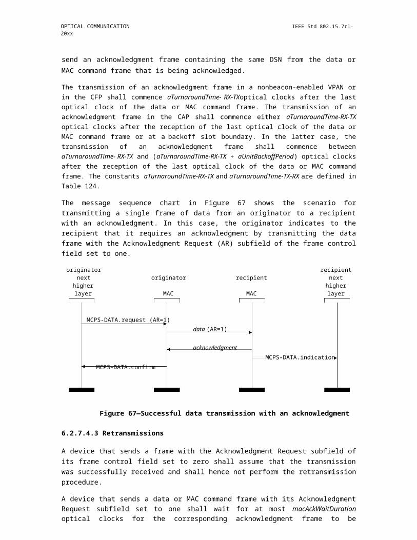
OPTICAL COMMUNICATION IEEE Std 802.15.7r1-20xx
7.2.6 Data service message sequence chart
Figure 147 illustrates a sequence of messages necessary for a successful data transfer between two devices. Figure 168 and Figure 169 also illustrate this, including the steps taken by the PHY.
Figure 147—Message sequence chart describing the MAC data service
7.3 MAC management service
The MLME-SAP allows the transport of management commands between the next higher layer and the MLME. Table 31 summarizes the primitives supported by the MLME through the MLME -SAP interface. Primitives marked with a diamond () are optional for an RFD. Primitives marked with an asterisk (*) are optional for both device types (i.e., RFD and FFD). The primitives are discussed in the subclauses referenced in this table.
Table 31—Summary of the primitives accessed through the MLME-SAP
Name Request Indication Response Confirm
MLME-ASSOCIATE 7.3.1.1 7.3.1.2 7.3.1.3 7.3.1.4
MLME-DISASSOCIATE 7.3.2.1 7.3.2.2 7.3.2.3
MLME-BEACON-NOTIFY 7.3.3.1
MLME-GET 7.3.4.1 7.3.4.2
MLME-GTS 7.3.5.1 7.3.5.2 7.3.5.3
MLME-RESET 7.3.6.1 7.3.6.2
MLME-RX-ENABLE 7.3.7.1 7.3.7.2
MLME-SCAN 7.3.8.1 7.3.8.2
MLME-COMM-STATUS 7.3.9.1
Copyright © 2011 IEEE. All rights reserved. 207

IEEE Std 802.15.7r1-20xx IEEE STANDARD FOR SHORT-RANGE WIRELESS
Table 31—Summary of the primitives accessed through the MLME-SAP (continued)
Name Request Indication Response Confirm
MLME-SET 7.3.10.1 7.3.10.2
MLME-START 7.3.11.1 7.3.11.2
MLME-SYNC 7.3.12.1*
MLME-SYNC-LOSS 7.3.13.1
MLME-POLL 7.3.14.1 7.3.14.2
7.3.1 Association primitives
MLME-SAP association primitives define how a device becomes associated with a VPAN.
All devices shall provide an interface for the request and confirm association primitives. The indication and response association primitives are optional for a device.
7.3.1.1 MLME-ASSOCIATE.request
The MLME-ASSOCIATE.request primitive allows a device to request an association with a coordinator.
The semantics of the MLME-ASSOCIATE.request primitive are as follows:
MLME-ASSOCIATE.request (LogicalChannel,CoordAddrMode,CoordVPANId,CoordAddress,CapabilityInformation,SecurityLevel,KeyIdMode,KeySource,KeyIndex,ColorAssoc)
Table 32 specifies the parameters for the MLME-ASSOCIATE.request primitive.
7.3.1.1.1 Appropriate usage
The MLME-ASSOCIATE.request primitive is generated by the next higher layer of an unassociated device and issued to its MLME to request an association with a VPAN through a coordinator. If the device wishes to associate through a coordinator on a beacon-enabled VPAN, the MLME may optionally track the beacon of that coordinator prior to issuing this primitive.
7.3.1.1.2 Effect on receipt
On receipt of the MLME-ASSOCIATE.request primitive, the MLME of an unassociated device first updates the appropriate PHY and MAC PIB attributes and then generates an association request command as shown in 6.7.1, as dictated by the association procedure described in 6.2.4.1.
208 Copyright © 20xx IEEE. All rights reserved.
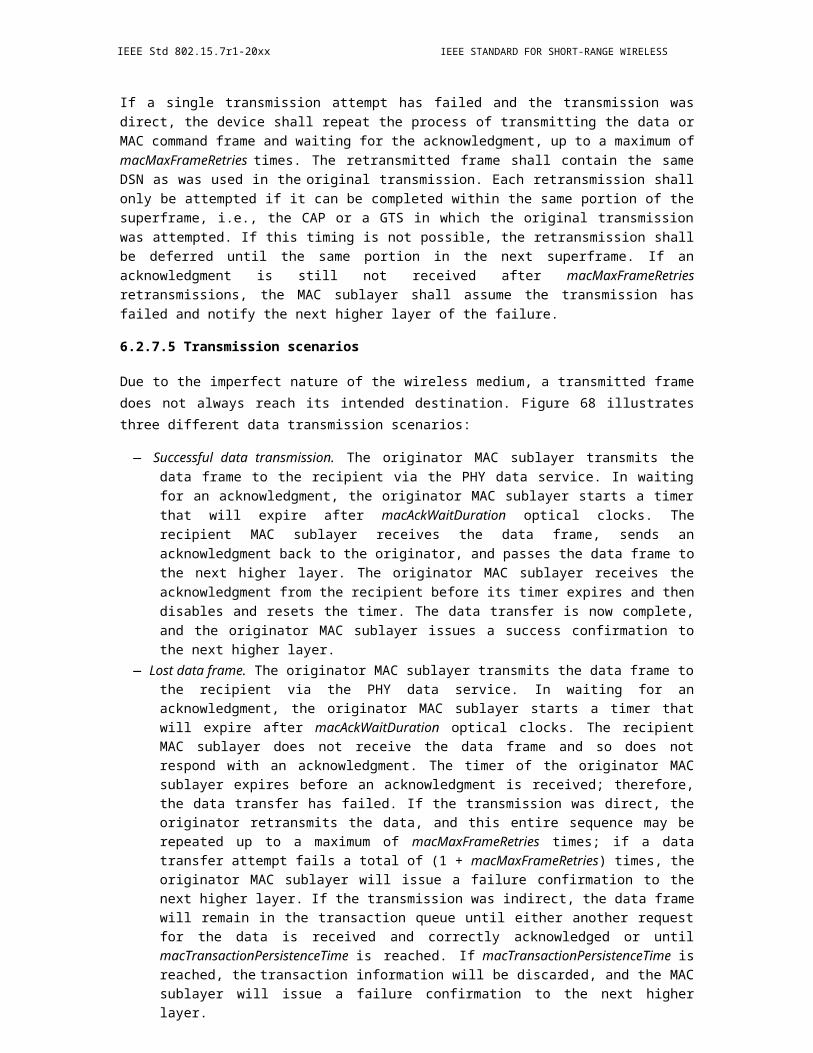
OPTICAL COMMUNICATION IEEE Std 802.15.7r1-20xx
Table 32—MLME-ASSOCIATE.request parameters
Name Type Valid range Description
LogicalChannel Integer Selected from the available The logical channel on which to attemptlogical channels supported association.by the PHY (see Table 87)
CoordAddrMode Integer 0x02–0x03 The coordinator addressing mode for thisprimitive and subsequent MPDU. This valuecan take one of the following values:
2 = 16-bit short address.3 = 64-bit extended address.
CoordVPANId Integer 0x0000–0xffff The VPAN identifier of the coordinator asspecified in the received beacon frame.
CoordAddress Device As specified by the The address of the coordinator with which toaddress CoordAddrMode associate.
parameter
CapabilityInformation Bitmap As defined in 6.7.19.1 Specifies the operational capabilities of theassociating device.
SecurityLevel Integer 0x00–0x07 The security level to be used (as defined inTable 67 in 8.4.2.1).
KeyIdMode Integer 0x00–0x03 The mode used to identify the key to be used(as defined in Table 68 in 8.4.2.2). Thisparameter is ignored if the SecurityLevelparameter is set to 0x00.
KeySource Set of 0, As specified by the The originator of the key to be used (see4, or 8 KeyIdMode parameter 8.4.4.1). This parameter is ignored if theoctets KeyIdMode parameter is ignored or set to
0x00.
KeyIndex Integer 0x01–0xff The index of the key to be used (see 8.4.4.2).This parameter is ignored if the KeyIdModeparameter is ignored or set to 0x00.
ColorAssoc Boolean TRUE or FALSE ColorAssoc shall be set as TRUE if the colorCVD frame is to be transmitted after theassociation request command is sent.
The SecurityLevel parameter specifies the level of security to be applied to the association request command frame. Typically, the association request command should not be implemented using security. However, if the device requesting association shares a key with the coordinator, then security may be specified.
If the SecurityLevel parameter is set to a valid value other than 0x00, indicating that security is required for this frame, the MLME will set the Security Enabled subfield of the frame control field to one. The MAC sublayer will perform outgoing processing on the frame based on the CoordAddress, SecurityLevel, KeyIdMode, KeySource, and KeyIndex parameters, as described in 8.2.1. If any error occurs during outgoing frame processing, the MLME will discard the frame and issue the MLME-ASSOCIATE.confirm primitive with the error status returned by outgoing frame processing.
If the association request command cannot be sent to the coordinator due to the unslotted random access algorithm indicating a busy channel, the MLME will issue the MLME-ASSOCIATE.confirm primitive with a status of CHANNEL_ACCESS_FAILURE.
Copyright © 2011 IEEE. All rights reserved. 209

IEEE Std 802.15.7r1-20xx IEEE STANDARD FOR SHORT-RANGE WIRELESS
If the MLME successfully transmits an association request command, the MLME will expect an acknowledgment in return. If an acknowledgment is not received, the MLME will issue the MLME-ASSOCIATE.confirm primitive with a status of NO_ACK (see 6.2.7.4).
If the MLME of an unassociated device successfully receives an acknowledgment to its association request command, the MLME will wait for a response to the request (see 6.2.4.1). If the MLME of the device does not receive a response, it will issue the MLME-ASSOCIATE.confirm primitive with a status of NO_DATA.
If the MLME of the device extracts an association response command frame from the coordinator, it will then issue the MLME-ASSOCIATE.confirm primitive with a status equal to the contents of the Association Status field in the association response command as shown in 6.7.2.3.
On receipt of the association request command, the MLME of the coordinator issues the MLME-ASSOCIATE.indication primitive.
If any parameter in the MLME-ASSOCIATE.request primitive is either not supported or out of range, the MLME will issue the MLME-ASSOCIATE.confirm primitive with a status of INVALID_PARAMETER.
7.3.1.2 MLME-ASSOCIATE.indication
The MLME-ASSOCIATE.indication primitive is used to indicate the reception of an association request command.
The semantics of the MLME-ASSOCIATE.indication primitive are as follows:
MLME-ASSOCIATE.indication (DeviceAddress,CapabilityInformation,SecurityLevel,KeyIdMode,KeySource,KeyIndex)
Table 33 specifies the parameters for the MLME-ASSOCIATE.indication primitive.
Table 33—MLME-ASSOCIATE.indication parameters
Name Type Valid range Description
DeviceAddress Device An extended 64-bit The address of the device requestingaddress IEEE address association.
CapabilityInformation Bitmap Refer to 6.7.19.1 The operational capabilities of the devicerequesting association.
SecurityLevel Integer 0x00–0x07 The security level purportedly used by thereceived MAC command frame (as defined inTable 67 in 8.4.2.1).
KeyIdMode Integer 0x00–0x03 The mode used to identify the key purportedlyused by the originator of the received frame (asdefined in Table 68 in 8.4.2.2). This parameteris invalid if the SecurityLevel parameter is setto 0x00.
210 Copyright © 20xx IEEE. All rights reserved.
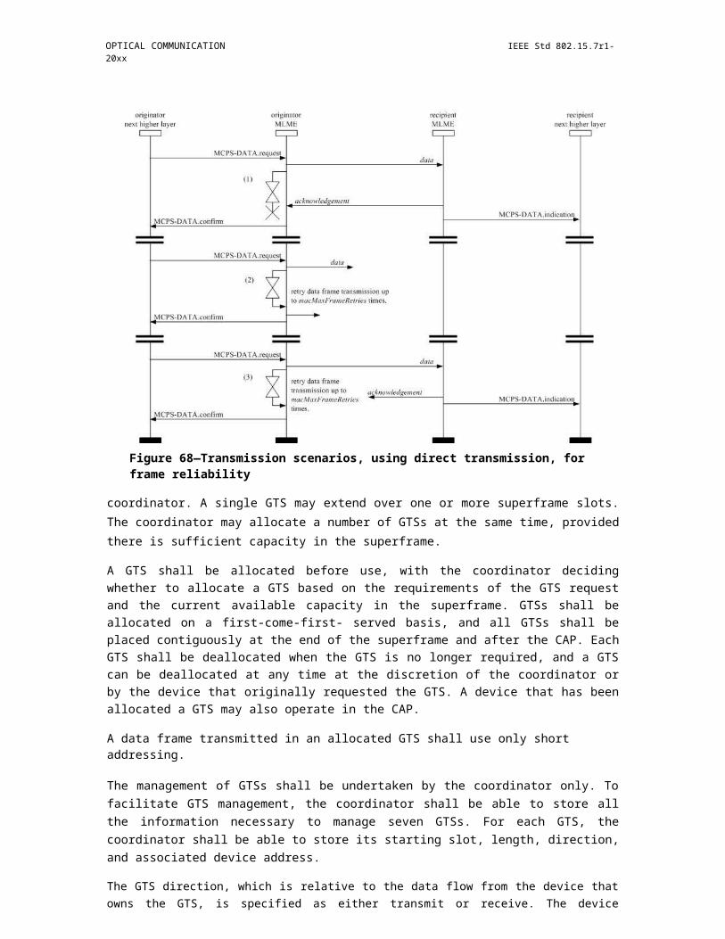
OPTICAL COMMUNICATION IEEE Std 802.15.7r1-20xx
Table 33—MLME-ASSOCIATE.indication parameters (continued)
Name Type Valid range Description
KeySource Set of 0, As specified by the The originator of the key purportedly used by4, or 8 KeyIdMode the originator of the received frame (seeoctets parameter 8.4.4.1). This parameter is invalid if the
KeyIdMode parameter is invalid or set to 0x00.
KeyIndex Integer 0x01–0xff The index of the key purportedly used by theoriginator of the received frame (see 8.4.4.2).This parameter is invalid if the KeyIdModeparameter is invalid or set to 0x00.
7.3.1.2.1 When generated
The MLME-ASSOCIATE.indication primitive is generated by the MLME of the coordinator and issued to its next higher layer to indicate the reception of an association request command (as defined in 6.7.1).
7.3.1.2.2 Appropriate usage
When the next higher layer of a coordinator receives the MLME- ASSOCIATE.indication primitive, the coordinator determines whether to accept or reject the unassociated device using an algorithm outside the scope of this standard. The next higher layer of the coordinator then issues the MLME-ASSOCIATE.response primitive to its MLME.
The association decision and the response should become available at the coordinator within a time of macResponseWaitTime (see 6.2.4.1). After this time, the device requesting association attempts to extract the association response command frame from the coordinator, using the method described in 6.2.7.3, in order to determine whether the association was successful.
7.3.1.3 MLME-ASSOCIATE.response
The MLME-ASSOCIATE.response primitive is used to initiate a response to an MLME-ASSOCIATE.indication primitive.
The semantics of the MLME-ASSOCIATE.response primitive are as follows:
MLME-ASSOCIATE.response (DeviceAddress,AssocShortAddress,status,CapabilityNegotiationResponse,SecurityLevel,KeyIdMode,KeySource,KeyIndex)
Table 34 specifies the parameters for the MLME-ASSOCIATE.response primitive.
Copyright © 2011 IEEE. All rights reserved. 211
IEEE Std 802.15.7r1-20xx IEEE STANDARD FOR SHORT-RANGE WIRELESS
Table 34—MLME-ASSOCIATE.response parameters
Name Type Valid range Description
DeviceAddress Device An extended 64-bit The address of the device requestingaddress IEEE address association.
AssocShortAddress Integer 0x0000–0xffff The 16-bit short device address allocated bythe coordinator on successful association.This parameter is set to 0xffff if theassociation was unsuccessful.
status Enumeration Refer to 6.7.2.3 The status of the association attempt.
CapabilityNegotiatio Integer 00–11 The coordinator indicates who will sendnResponse color compensation information (same
definitions and usage as the colorstabilization scheme subfield in Table 22).
SecurityLevel Integer 0x00–0x07 The security level to be used (as defined inTable 67 in 8.4.2.1).
KeyIdMode Integer 0x00–0x03 The mode used to identify the key to beused (as defined in Table 68 in 8.4.2.2). Thisparameter is ignored if the SecurityLevelparameter is set to 0x00.
KeySource Set of 0, 4, or As specified by the The originator of the key to be used (see8 octets KeyIdMode parameter 8.4.4.1). This parameter is ignored if the
KeyIdMode parameter is ignored or set to0x00.
KeyIndex Integer 0x01–0xff The index of the key to be used (see8.4.4.2). This parameter is ignored if theKeyIdMode parameter is ignored or set to0x00.
7.3.1.3.1 Appropriate usage
The MLME -ASSOCIATE.response primitive is generated by the next higher layer of a coordinator and issued to its MLME in order to respond to the MLME-ASSOCIATE.indication primitive.
7.3.1.3.2 Effect on receipt
When the MLME of a coordinator receives the MLME-ASSOCIATE.response primitive, it generates an association response command as shown in 6.7.2. The command frame is sent to the device requesting association using indirect transmission, i.e., the command frame is added to the list of pending transactions stored on the coordinator and extracted at the discretion of the device concerned using the method described in 6.2.7.3.
If the SecurityLevel parameter is set to a valid value other than 0x00, indicating that security is required for this frame, the MLME will set the Security Enabled subfield of the frame control field to one. The MAC sublayer will perform outgoing processing on the frame based the DeviceAddress, SecurityLevel, KeyIdMode, KeySource, and KeyIndex parameters, as described in 8.2.1. If any error occurs during outgoing frame processing, the MLME will discard the frame and issue the MLME-COMM-STATUS.indication primitive with the error status returned by outgoing frame processing.
Upon receipt of the MLME-ASSOCIATE.response primitive, the coordinator attempts to add the information contained in the primitive to its list of pending transactions. If there is no capacity to store the
212 Copyright © 20xx IEEE. All rights reserved.
OPTICAL COMMUNICATION IEEE Std 802.15.7r1-20xx
transaction, the MAC sublayer will discard the frame and issue the MLME- COMM- STATUS.indication primitive with a status of TRANSACTION_OVERFLOW. If there is capacity to store the transaction, the coordinator will add the information to the list. If the transaction is not handled within macTransactionPersistenceTime, the transaction information will be discarded and the MAC sublayer will issue the MLME-COMM-STATUS.indication primitive with a status of TRANSACTION_EXPIRED. The transaction handling procedure is described in 6.2.6.
If the frame was successfully transmitted and an acknowledgment was received, if requested, the MAC sublayer will issue the MLME-COMM-STATUS.indication primitive with a status of SUCCESS.
If any parameter in the MLME-ASSOCIATE.response primitive is not supported or is out of range, the MAC sublayer will issue the MLME-COMM-STATUS.indication primitive with a status ofINVALID_PARAMETER.
7.3.1.4 MLME-ASSOCIATE.confirm
The MLME-ASSOCIATE.confirm primitive is used to inform the next higher layer of the initiating device whether its request to associate was successful or unsuccessful.
The semantics of the MLME-ASSOCIATE.confirm primitive are as follows:
MLME-ASSOCIATE.confirm (AssocShortAddress,status,CapabilityNegotiationResponse,SecurityLevel,KeyIdMode,KeySource,KeyIndex)
Table 35 specifies the parameters for the MLME-ASSOCIATE.confirm primitive.
Table 35—MLME-ASSOCIATE.confirm parameters
Name Type Valid range Description
AssocShortAddress Integer 0x0000–0xffff The short device address allocated bythe coordinator on successfulassociation. This parameter will beequal to 0xffff if the associationattempt was unsuccessful.
Copyright © 2011 IEEE. All rights reserved. 213

IEEE Std 802.15.7r1-20xx IEEE STANDARD FOR SHORT-RANGE WIRELESS
Table 35—MLME-ASSOCIATE.confirm parameters (continued)
Name Type Valid range Description
status Enumeration The value of the Status field of the The status of the association attempt.association response command(as defined in 6.7.2.3),SUCCESS,CHANNEL_ACCESS_FAILURE,NO_ACK,NO_DATA,COUNTER_ERROR,FRAME_TOO_LONG,IMPROPER_KEY_TYPE,IMPROPER_SECURITY_LEVEL,SECURITY_ERROR,UNAVAILABLE_KEY,UNSUPPORTED_LEGACY,UNSUPPORTED_SECURITYINVALID_PARAMETER
CapabilityNegotiati Integer 00–11 Coordinator indicates who will sendonResponse (see Table 22).
SecurityLevel Integer 0x00–0x07 If the primitive was generatedfollowing failed outgoing processingof an association request command:
The security level to be used (asdefined in Table 67 in 8.4.2.1).
If the primitive was generatedfollowing receipt of an associationresponse command:
The security level purportedly usedby the received frame (as defined inTable 67 in 8.4.2.1).
KeyIdMode Integer 0x00–0x03 If the primitive was generatedfollowing failed outgoing processingof an association request command:
The mode used to identify the key tobe used (as defined in Table 68 in8.4.2.2). This parameter is ignored ifthe SecurityLevel parameter is set to0x00.
If the primitive was generatedfollowing receipt of an associationresponse command:
The mode used to identify the keypurportedly used by the originator ofthe received frame (as defined inTable 68 in 8.4.2.2). This parameteris invalid if the SecurityLevelparameter is set to 0x00.
214 Copyright © 20xx IEEE. All rights reserved.

OPTICAL COMMUNICATION IEEE Std 802.15.7r1-20xx
Table 35—MLME-ASSOCIATE.confirm parameters (continued)
Name Type Valid range Description
KeySource Set of 0, 4, As specified by the KeyIdMode If the primitive was generatedor 8 octets parameter following failed outgoing processing
of an association request command:
The originator of the key to be used(see 8.4.4.1). This parameter isignored if the KeyIdMode parameteris ignored or set to 0x00.
If the primitive was generatedfollowing receipt of an associationresponse command:
The originator of the key purportedlyused by the originator of the receivedframe (see 8.4.4.1). This parameter isinvalid if the KeyIdMode parameteris invalid or set to 0x00.
KeyIndex Integer 0x01–0xff If the primitive was generatedfollowing failed outgoing processingof an association request command:
The index of the key to be used (see8.4.4.2). This parameter is ignored ifthe KeyIdMode parameter is ignoredor set to 0x00.
If the primitive was generatedfollowing receipt of an associationresponse command:
The index of the key purportedlyused by the originator of the receivedframe (see 8.4.4.2). This parameter isinvalid if the KeyIdMode parameteris invalid or set to 0x00.
7.3.1.4.1 When generated
The MLME -ASSOCIATE.confirm primitive is generated by the initiating MLME and issued to its next higher layer in response to an MLME-ASSOCIATE.request primitive. If the request was successful, the status parameter will indicate a successful association, as contained in the Status field of the association response command. Otherwise, the status parameter indicates either an error code from the received association response command or the appropriate error code from Table 35. The status values are fully described in 7.3.1.1.2 and subclauses referenced by 7.3.1.1.2.
7.3.1.4.2 Appropriate usage
On receipt of the MLME- ASSOCIATE.confirm primitive, the next higher layer of the initiating device is notified of the result of its request to associate with a coordinator. If the association attempt was successful, the status parameter will indicate a successful association, as contained in the Status field of the association response command, and the device will be provided with a 16-bit short address as specified in Table 3 in 6.2.4.1. If the association attempt was unsuccessful, the address will be equal to 0xffff, and the status parameter will indicate the error.
Copyright © 2011 IEEE. All rights reserved. 215

IEEE Std 802.15.7r1-20xx IEEE STANDARD FOR SHORT-RANGE WIRELESS
7.3.1.5 Association-message sequence charts
Figure 148 illustrates a sequence of messages that may be used by a device that is not tracking the beacon of the coordinator, specified in 6.2.7.3, to successfully associate with a VPAN. Figure 164 and Figure 165, and described in 7.7, illustrate this same scenario, including steps taken by the PHY, for a device associating with a coordinator and for a coordinator allowing association by a device, respectively.
Figure 148—Message sequence chart for association
7.3.2 Disassociation primitives
The MLME-SAP disassociation primitives define how a device can disassociate from a VPAN.
All devices shall provide an interface for these disassociation primitives.
7.3.2.1 MLME-DISASSOCIATE.request
The MLME -DISASSOCIATE.request primitive is used by an associated device to notify the coordinator of its intent to leave the VPAN. It is also used by the coordinator to instruct an associated device to leave the VPAN.
216 Copyright © 20xx IEEE. All rights reserved.
OPTICAL COMMUNICATION IEEE Std 802.15.7r1-20xx
The semantics of the MLME-DISASSOCIATE.request primitive are as follows:
MLME-DISASSOCIATE.request (DeviceAddrMode,DeviceVPANId,DeviceAddress,DisassociateReason,TxIndirect,SecurityLevel,KeyIdMode,KeySource,KeyIndex,ColorDisAssoc)
Table 36 specifies the parameters for the MLME-DISASSOCIATE.request primitive.
Table 36—MLME-DISASSOCIATE.request parameters
Name Type Valid range Description
DeviceAddrMode Integer 0x02–0x03 The addressing mode of the device to whichto send the disassociation notificationcommand.
DeviceVPANId Integer 0x0000–0xffff The VPAN identifier of the device to which tosend the disassociation notificationcommand.
DeviceAddress Device As specified by the The address of the device to which to send theaddress DeviceAddrMode disassociation notification command.
parameter.
DisassociateReason Integer 0x00–0xff The reason for the disassociation (as definedin 6.7.3.2).
TxIndirect Boolean TRUE or FALSE TRUE if the disassociation notification com-mand is to be sent indirectly.
SecurityLevel Integer 0x00–0x07 The security level to be used (as defined inTable 67 in 8.4.2.1).
KeyIdMode Integer 0x00–0x03 The mode used to identify the key to be used(as defined in Table 68 in 8.4.2.2). Thisparameter is ignored if the SecurityLevelparameter is set to 0x00.
KeySource Set of 0, 4, or As specified by the The originator of the key to be used (see8 octets KeyIdMode parameter 8.4.4.1). This parameter is ignored if the
KeyIdMode parameter is ignored or set to0x00.
KeyIndex Integer 0x01–0xff The index of the key to be used (see 8.4.4.2).This parameter is ignored if the KeyIdModeparameter is ignored or set to 0x00.
ColorDisAssoc Boolean TRUE or FALSE ColorDisAssoc shall be set as TRUE if thecolor CVD frame is to be transmitted after thedisassociation notification command is sent.
Copyright © 2011 IEEE. All rights reserved. 217
IEEE Std 802.15.7r1-20xx IEEE STANDARD FOR SHORT-RANGE WIRELESS
7.3.2.1.1 Appropriate usage
The MLME-DISASSOCIATE.request primitive is generated by the next higher layer of an associated device and issued to its MLME to request disassociation from the VPAN. It is also generated by the next higher layer of the coordinator and issued to its MLME to instruct an associated device to leave the VPAN.
7.3.2.1.2 Effect on receipt
On receipt of the MLME-DISASSOCIATE.request primitive, the MLME compares the DeviceVPANId parameter with macVPANId. If the DeviceVPANId parameter is not equal to macVPANId, the MLME issues the MLME-DISASSOCIATE.confirm primitive with a status of INVALID_PARAMETER. If the DeviceVPANId parameter is equal to macVPANId, the MLME evaluates the primitive address fields.
If the DeviceAddrMode parameter is equal to 0x02 and the DeviceAddress parameter is equal to macCoordShortAddress or if the DeviceAddrMode parameter is equal to 0x03 and the DeviceAddress parameter is equal to macCoordExtendedAddress, the TxIndirect parameter is ignored, and the MLME sends a disassociation notification command (see 6.7.3) to its coordinator in the CAP for a beacon-enabled VPAN or immediately for a nonbeacon-enabled VPAN.
If the DeviceAddrMode parameter is equal to 0x02 and the DeviceAddress parameter is not equal to macCoordShortAddress or if the DeviceAddrMode parameter is equal to 0x03 and the DeviceAddress parameter is not equal to macCoordExtendedAddress, and if this primitive was received by the MLME of a coordinator with the TxIndirect parameter set to TRUE, the disassociation notification command will be sent using indirect transmission, i.e., the command frame is added to the list of pending transactions stored on the coordinator and extracted at the discretion of the device concerned using the method described in 6.2.7.3.
If the DeviceAddrMode parameter is equal to 0x02 and the DeviceAddress parameter is not equal to macCoordShortAddress or if the DeviceAddrMode parameter is equal to 0x03 and the DeviceAddress parameter is not equal to macCoordExtendedAddress, and if this primitive was received by the MLME of a coordinator with the TxIndirect parameter set to FALSE, the MLME sends a disassociation notification command to the device in the CAP for a beacon-enabled VPAN or immediately for a nonbeacon-enabled VPAN.
Otherwise, the MLME issues the MLME- DISASSOCIATE.confirm primitive with a status of INVALID_PARAMETER and does not generate a disassociation notification command.
If the disassociation notification command is to be sent using indirect transmission and there is no capacity to store the transaction, the MLME will discard the frame and issue the MLME-DISASSOCIATE.confirm primitive with a status of TRANSACTION_OVERFLOW. If there is capacity to store the transaction, the coordinator will add the information to the list. If the transaction is not handled within macTransaction-PersistenceTime, the transaction information will be discarded, and the MLME will issue the MLME-DISASSOCIATE.confirm with a status of TRANSACTION_EXPIRED. The transaction handling procedure is described in 6.2.6.
If the disassociation notification command cannot be sent due to an unslotted random access algorithm failure and this primitive was received either by the MLME of a coordinator with the TxIndirect parameter set to FALSE or by the MLME of a device, the MLME will issue the MLME-DISASSOCIATE.confirm primitive with a status of CHANNEL_ACCESS_FAILURE.
If the SecurityLevel parameter is set to a valid value other than 0x00, indicating that security is required for this frame, the MLME will set the Security Enabled subfield of the frame control field to one. The MAC sublayer will perform outgoing processing on the frame based on the DeviceAddress, SecurityLevel, KeyIdMode, KeySource, and KeyIndex parameters, as described in 8.2.1. If any error occurs during
218 Copyright © 20xx IEEE. All rights reserved.

OPTICAL COMMUNICATION IEEE Std 802.15.7r1-20xx
outgoing frame processing, the MLME will discard the frame and issue the MLME-DISASSOCIATE.confirm primitive with the error status returned by outgoing frame processing.
If the MLME successfully transmits a disassociation notification command, the MLME will expect an acknowledgment in return. If an acknowledgment is not received and this primitive was received either by the MLME of a coordinator with the TxIndirect parameter set to FALSE or by the MLME of a device, the MLME will issue the MLME-DISASSOCIATE.confirm primitive with a status of NO_ACK (see 6.2.7.4).
If the MLME successfully transmits a disassociation notification command and receives an acknowledgment in return, the MLME will issue the MLME-DISASSOCIATE.confirm primitive with a status of SUCCESS.
On receipt of the disassociation notification command, the MLME of the recipient issues the MLME-DISASSOCIATE.indication primitive.
If any parameter in the MLME-DISASSOCIATE.request primitive is not supported or is out of range, the MLME will issue the MLME-DISASSOCIATE.confirm primitive with a status ofINVALID_PARAMETER.
7.3.2.2 MLME-DISASSOCIATE.indication
The MLME-DISASSOCIATE.indication primitive is used to indicate the reception of a disassociation notification command.
The semantics of the MLME-DISASSOCIATE.indication primitive are as follows:
MLME-DISASSOCIATE.indication (DeviceAddress,DisassociateReason,SecurityLevel,KeyIdMode,KeySource,KeyIndex)
Table 37 specifies the parameters for the MLME-DISASSOCIATE.indication primitive.
7.3.2.2.1 When generated
The MLME-DISASSOCIATE.indication primitive is generated by the MLME and issued to its next higher layer on receipt of a disassociation notification command.
7.3.2.2.2 Appropriate usage
The next higher layer is notified of the reason for the disassociation.
7.3.2.3 MLME-DISASSOCIATE.confirm
The MLME-DISASSOCIATE.confirm primitive reports the results of an MLME-DISASSOCIATE.request primitive.
Copyright © 2011 IEEE. All rights reserved. 219

IEEE Std 802.15.7r1-20xx IEEE STANDARD FOR SHORT-RANGE WIRELESS
Table 37—MLME-DISASSOCIATE.indication parameters
Name Type Valid range Description
DeviceAddress Device An extended 64-bit The address of the device requestingaddress IEEE address disassociation.
DisassociateReason Integer 0x00–0xff The reason for the disassociation (as definedin 6.7.3.2).
SecurityLevel Integer 0x00–0x07 The security level purportedly used by thereceived MAC command frame (as defined inTable 67 in 8.4.2.1).
KeyIdMode Integer 0x00–0x03 The mode used to identify the keypurportedly used by the originator of thereceived frame (as defined in Table 68 in8.4.2.2). This parameter is invalid if theSecurityLevel parameter is set to 0x00.
KeySource Set of 0, 4, or As specified by the The originator of the key purportedly used by8 octets KeyIdMode parameter the originator of the received frame (see
8.4.4.1). This parameter is invalid if theKeyIdMode parameter is invalid or set to0x00.
KeyIndex Integer 0x01–0xff The index of the key purportedly used by theoriginator of the received frame (see 8.4.4.2).This parameter is invalid if the KeyIdModeparameter is invalid or set to 0x00.
The semantics of the MLME-DISASSOCIATE.confirm primitive are as follows:
MLME-DISASSOCIATE.confirm ( status,
DeviceAddrMode,DeviceVPANId,DeviceAddress)
Table 38 specifies the parameters for the MLME-DISASSOCIATE.confirm primitive.
7.3.2.3.1 When generated
The MLME-DISASSOCIATE.confirm primitive is generated by the initiating MLME and issued to its next higher layer in response to an MLME -DISASSOCIATE.request primitive. This primitive returns a status of either SUCCESS, indicating that the disassociation request was successful, or the appropriate error code. The status values are fully described in 7.3.2.1.2 and subclauses referenced by 7.3.2.1.2.
7.3.2.3.2 Appropriate usage
On receipt of the MLME- DISASSOCIATE.confirm primitive, the next higher layer of the initiating device is notified of the result of the disassociation attempt. If the disassociation attempt was successful, the status parameter will be set to SUCCESS. Otherwise, the status parameter indicates the error.
220 Copyright © 20xx IEEE. All rights reserved.

OPTICAL COMMUNICATION IEEE Std 802.15.7r1-20xx
Table 38—MLME-DISASSOCIATE.confirm parameters
Name Type Valid range Description
status Enumeration SUCCESS, The status of the disassociationTRANSACTION_OVERFLOW, attempt.TRANSACTION_EXPIRED,NO_ACK,CHANNEL_ACCESS_FAILURE,COUNTER_ERROR,FRAME_TOO_LONG,UNAVAILABLE_KEY,UNSUPPORTED_SECURITY,INVALID_PARAMETER
DeviceAddrMode Integer 0x02–0x03 The addressing mode of the devicethat has either requesteddisassociation or been instructed todisassociate by its coordinator.
DeviceVPANId Integer 0x0000–0xffff The VPAN identifier of the devicethat has either requesteddisassociation or been instructed todisassociate by its coordinator.
DeviceAddress Device As specified by the The address of the device that hasaddress DeviceAddrMode parameter. either requested disassociation or
been instructed to disassociate by itscoordinator.
7.3.2.4 Disassociation-message sequence charts
The request to disassociate may originate either from a device or from the coordinator through which the device has associated. Figure 149 illustrates the sequence of messages necessary for a device to successfully disassociate itself from the VPAN.
Figure 149—Message sequence chart for disassociation initiated by a device
Figure 150 illustrates the sequence necessary for a coordinator in a beacon-enabled VPAN to successfully disassociate a device from its VPAN using indirect transmission.
Copyright © 2011 IEEE. All rights reserved. 221
IEEE Std 802.15.7r1-20xx IEEE STANDARD FOR SHORT-RANGE WIRELESS
Figure 150—Message sequence chart for disassociation initiated by a coordinator, using indirect transmission, in a beacon-enabled VPAN
7.3.3 Beacon notification primitive
The MLME-SAP beacon notification primitive defines how a device may be notified when a beacon is received during normal operating conditions.
All devices shall provide an interface for the beacon notification primitive.
7.3.3.1 MLME-BEACON-NOTIFY.indication
The MLME-BEACON-NOTIFY.indication primitive is used to send parameters contained within a beacon frame received by the MAC sublayer to the next higher layer. The primitive also sends a measure of the WQI and the time the beacon frame was received.
222 Copyright © 20xx IEEE. All rights reserved.
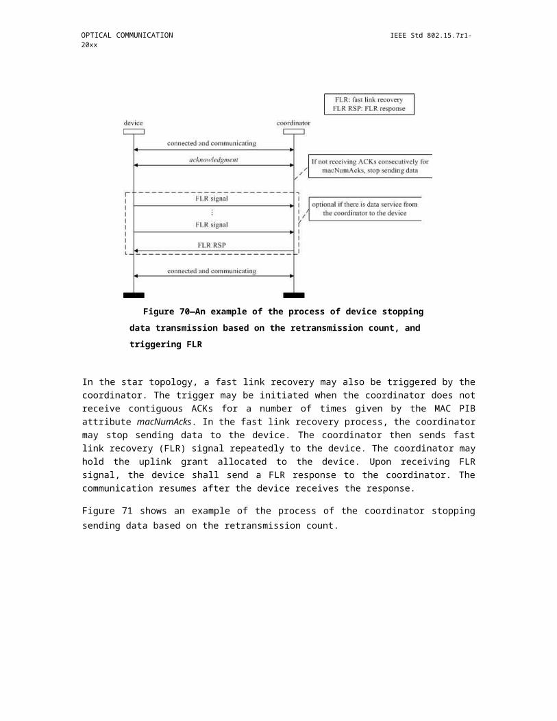
OPTICAL COMMUNICATION IEEE Std 802.15.7r1-20xx
The semantics of the MLME-BEACON-NOTIFY.indication primitive are as follows:
MLME-BEACON-NOTIFY.indication ( BSN,
VPANDescriptor,PendAddrSpec,AddrList,sduLength, sdu)
Table 39 specifies the parameters for the MLME-BEACON-NOTIFY.indication primitive.
Table 39—MLME-BEACON-NOTIFY.indication parameters
Name Type Valid range Description
BSN Integer 0x00–0xff The beacon sequence number.
VPANDescriptor VPANDescriptor Refer to Table 40 The VPANDescriptor for the receivedvalue beacon.
PendAddrSpec Bitmap Refer to 6.4.6.1.6 The beacon pending addressspecification.
AddrList List of device — The list of addresses of the devices foraddresses which the beacon source has data.
sduLength Integer 0 – aMaxBeaconPayloadLength The number of octets contained in thebeacon payload of the beacon framereceived by the MAC sublayer.
sdu Set of octets — The set of octets comprising the beaconpayload to be transferred from the MACsublayer entity to the next higher layer.
Table 40 describes the elements of the VPANDescriptor type.
Table 40—Elements of VPAN descriptor
Name Type Valid range Description
CoordAddrMode Integer 0x02–0x03 The coordinator addressing modecorresponding to the received beacon frame.This value can take one of the followingvalues:2 = 16-bit short address.3 = 64-bit extended address.
CoordVPANId Integer 0x0000–0xffff The VPAN identifier of the coordinator asspecified in the received beacon frame.
CoordAddress Device As specified by the The address of the coordinator as specified inaddress CoordAddrMode parameter the received beacon frame.
Copyright © 2011 IEEE. All rights reserved. 223

IEEE Std 802.15.7r1-20xx IEEE STANDARD FOR SHORT-RANGE WIRELESS
Table 40—Elements of VPAN descriptor (continued)
Name Type Valid range Description
LogicalChannel Integer Selected from the available The current logical channel occupied by thelogical channels supported by network.the PHY (see Table 87).
SuperframeSpec Bitmap Refer to 6.4.6.1.2 The superframe specification as specified in thereceived beacon frame.
GTSPermit Boolean TRUE or FALSE TRUE if the beacon is from the coordinatorthat is accepting GTS requests.
LinkQuality Integer 0x00–0xff The WQI at which the network beacon wasreceived. Lower values represent lower WQI(see 6.7.19.2).
TimeStamp Integer 0x000000–0xffffff The time at which the beacon frame wasreceived, in symbols. This value is equal to thetimestamp taken when the beacon frame wasreceived, as described in 6.2.5.1.
This is a 24-bit value, and the precision of thisvalue shall be a minimum of 20 bits, with thelowest 4 bits being the least significant.
SecurityFailure Enumer- SUCCESS, SUCCESS if there was no error in the securityation COUNTER_ERROR, processing of the frame. One of the other status
IMPROPER_KEY_TYPE, codes indicating an error in the securityIMPROPER_SECURITY_LE processing otherwise (see 8.2.3).VEL, SECURITY_ERROR,UNAVAILABLE_KEY,UNSUPPORTED_LEGACY,UNSUPPORTED_SECURITY
SecurityLevel Integer 0x00–0x07 The security level purportedly used by thereceived beacon frame (as defined in Table 67in 8.4.2.1).
KeyIdMode Integer 0x00–0x03 The mode used to identify the key purportedlyused by the originator of the received frame (asdefined in Table 68 in 8.4.2.2). This parameteris invalid if the SecurityLevel parameter is setto 0x00.
KeySource Set of 0, As specified by the The originator of the key purportedly used by4, or 8 KeyIdMode parameter the originator of the received frame (seeoctets 8.4.4.1). This parameter is invalid if the
KeyIdMode parameter is invalid or set to 0x00.
KeyIndex Integer 0x01–0xff The index of the key purportedly used by theoriginator of the received frame (see 8.4.4.2).This parameter is invalid if the KeyIdModeparameter is invalid or set to 0x00.
7.3.3.1.1 When generated
The MLME -BEACON-NOTIFY.indication primitive is generated by the MLME and issued to its next higher layer upon receipt of a beacon frame either when macAutoRequest is set to FALSE or when the beacon frame contains one or more octets of payload.
224 Copyright © 20xx IEEE. All rights reserved.
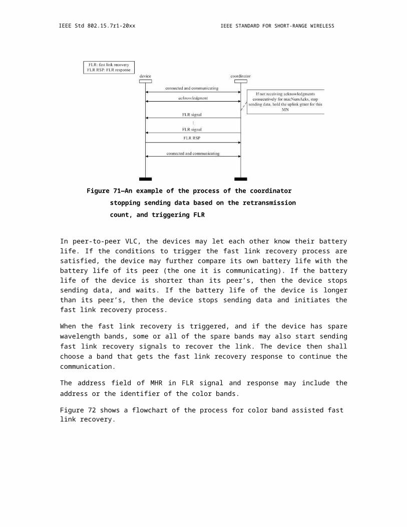
OPTICAL COMMUNICATION IEEE Std 802.15.7r1-20xx
7.3.3.1.2 Appropriate usage
On receipt of the MLME-BEACON- NOTIFY.indication primitive, the next higher layer is notified of the arrival of a beacon frame at the MAC sublayer.
7.3.4 Primitives for reading PIB attributes
The MLME-SAP get primitives define how to read values from the PIB.
All devices shall provide an interface for these get primitives.
7.3.4.1 MLME-GET.request
The MLME-GET.request primitive requests information about a given PIB attribute.
The semantics of the MLME-GET.request primitive are as follows:
MLME-GET.request (PIBAttribute,PIBAttributeIndex)
Table 41 specifies the parameters for the MLME-GET.request primitive.
Table 41—MLME-GET.request parameters
Name Type Valid range Description
PIBAttribute Integer Refer to Table 62 The identifier of the PIB attribute to read.
PIBAttributeIndex Integer Attribute specific; The index within the table of the specified PIBas defined in Table 62 attribute to read. This parameter is valid only
for MAC PIB attributes that are tables; it isignored when accessing PHY PIB attributes.
7.3.4.1.1 Appropriate usage
The MLME -GET.request primitive is generated by the next higher layer and issued to its MLME to obtain information from the PIB.
7.3.4.1.2 Effect on receipt
On receipt of the MLME-GET.request primitive, the MLME checks to see if the PIB attribute is a MAC PIB attribute or PHY PIB attribute. If the requested attribute is a MAC attribute, the MLME attempts to retrieve the requested MAC PIB attribute from its database. If the identifier of the PIB attribute is not found in the database, the MLME will issue the MLME-GET.confirm primitive with a status of UNSUPPORTED_ATTRIBUTE. If the PIBAttributeIndex parameter specifies an index for a table that is out of range, the MLME will issue the MLME-GET.confirm primitive with a status of INVALID_INDEX. If the requested MAC PIB attribute is successfully retrieved, the MLME will issue the MLME-GET.confirm primitive with a status of SUCCESS.
Copyright © 2011 IEEE. All rights reserved. 225

IEEE Std 802.15.7r1-20xx IEEE STANDARD FOR SHORT-RANGE WIRELESS
If the requested attribute is a PHY PIB attribute, the request is passed to the PHY by issuing the PLME-GET.request primitive. Once the MLME receives the PLME-GET.confirm primitive, it will translate the received status value because the status values used by the PHY are not the same as those used by the MLME (e.g., the status values for SUCCESS are 0x00 and 0x07 in the MAC and PHY enumeration tables, respectively). Following the translation, the MLME will issue the MLME-GET.confirm primitive to the next higher layer with the status parameter resulting from the translation and the PIBAttribute and PIBAttributeValue parameters equal to those returned by the PLME primitive.
7.3.4.2 MLME-GET.confirm
The MLME-GET.confirm primitive reports the results of an information request from the PIB.
The semantics of the MLME-GET.confirm primitive are as follows:
MLME-GET.confirm (status,PIBAttribute,PIBAttributeIndex,PIBAttributeValue)
Table 42 specifies the parameters for the MLME-GET.confirm primitive.
Table 42—MLME-GET.confirm parameters
Name Type Valid range Description
status Enumeration SUCCESS, The result of the request for PIBUNSUPPORTED_ATTRIBUTE attribute information.or INVALID_INDEX
PIBAttribute Integer Refer to Table 62 The identifier of the PIB attribute thatwas read.
PIBAttributeIndex Integer Attribute specific; The index within the table or array ofas defined in Table 62 the specified PIB attribute to read. This
parameter is valid only for MAC PIBattributes that are tables or arrays; it isignored when accessing PHY PIBattributes.
PIBAttributeValue Various Attribute specific; The value of the indicated PIB attributeas defined in Table 62 that was read.
This parameter has zero length whenthe status parameter is set toUNSUPPORTED_ATTRIBUTE.
7.3.4.2.1 When generated
The MLME-GET.confirm primitive is generated by the MLME and issued to its next higher layer in response to an MLME- GET.request primitive. This primitive returns a status of either SUCCESS, indicating that the request to read a PIB attribute was successful, or an error code of UNSUPPORTED_ATTRIBUTE. When an error code of UNSUPPORTED_ATTRIBUTE is returned, the PIBAttribute value parameter will be set to length zero. The status values are fully described in 7.3.4.1.2.
226 Copyright © 20xx IEEE. All rights reserved.
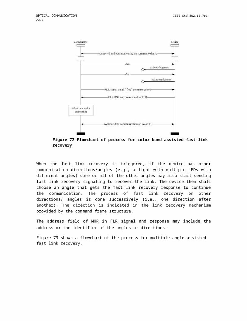
OPTICAL COMMUNICATION IEEE Std 802.15.7r1-20xx
7.3.4.2.2 Appropriate usage
On receipt of the MLME -GET.confirm primitive, the next higher layer is notified of the results of its request to read a PIB attribute. If the request to read a PIB attribute was successful, the status parameter will be set to SUCCESS. Otherwise, the status parameter indicates the error.
7.3.5 GTS management primitives
The MLME-SAP GTS management primitives define how GTSs are requested and maintained. A device wishing to use these primitives and GTSs in general will already be tracking the beacons of its coordinator.
These GTS management primitives are optional.
7.3.5.1 MLME-GTS.request
The MLME-GTS.request primitive allows a device to send a request to the coordinator to allocate a new GTS or to deallocate an existing GTS. This primitive is also used by the coordinator to initiate a GTS deallocation.
The semantics of the MLME-GTS.request primitive are as follows:
MLME-GTS.request (GTSCharacteristics,SecurityLevel,KeyIdMode,KeySource,KeyIndex)
Table 43 specifies the parameters for the MLME-GTS.request primitive.
Table 43—MLME-GTS.request parameters
Name Type Valid range Description
GTSCharacteristics GTS Refer to 6.7.13.2 The characteristics of the GTS request, includingcharacteristics whether the request is for the allocation of a new
GTS or the deallocation of an existing GTS.
SecurityLevel Integer 0x00–0x07 The security level to be used (as defined in Table 67in 8.4.2.1).
KeyIdMode Integer 0x00–0x03 The mode used to identify the key to be used (asdefined in Table 68 in 8.4.2.2). This parameter isignored if the SecurityLevel parameter is set to 0x00.
KeySource Set of 0, 4, or As specified by The originator of the key to be used (see 8.4.4.1).8 octets the KeyIdMode This parameter is ignored if the KeyIdMode
parameter parameter is ignored or set to 0x00.
KeyIndex Integer 0x01–0xff The index of the key to be used (see 8.4.4.2). Thisparameter is ignored if the KeyIdMode parameter isignored or set to 0x00.
Copyright © 2011 IEEE. All rights reserved. 227

IEEE Std 802.15.7r1-20xx IEEE STANDARD FOR SHORT-RANGE WIRELESS
7.3.5.1.1 Appropriate usage
The MLME-GTS.request primitive is generated by the next higher layer of a device and issued to its MLME to request the allocation of a new GTS or to request the deallocation of an existing GTS. It is also generated by the next higher layer of the coordinator and issued to its MLME to request the deallocation of an existing GTS.
7.3.5.1.2 Effect on receipt
On receipt of the MLME -GTS.request primitive by a device, the MLME of a device attempts to generate a GTS request command, specified in 6.7.13, with the information contained in this primitive and, if successful, sends it to the coordinator.
If macShortAddress is equal to 0xfffe or 0xffff, the device is not permitted to request a GTS. In this case, the MLME issues the MLME-GTS.confirm primitive containing a status of NO_SHORT_ADDRESS.
If the SecurityLevel parameter is set to a valid value other than 0x00, indicating that security is required for this frame, the MLME will set the Security Enabled subfield of the frame control field to one. The MAC sublayer will perform outgoing processing on the frame based on macCoordExtendedAddress and the SecurityLevel, KeyIdMode, KeySource, and KeyIndex parameters, as described in 8.2.1. If any error occurs during outgoing frame processing, the MLME will discard the frame and issue the MLME-GTS.confirm primitive with the error status returned by outgoing frame processing.
If the GTS request command cannot be sent due to an unslotted random access algorithm failure, the MLME will issue the MLME-GTS.confirm primitive with a status of CHANNEL_ACCESS_FAILURE.
If the MLME successfully transmits a GTS request command, the MLME will expect an acknowledgment in return. If an acknowledgment is not received, the MLME will issue the MLME-GTS.confirm primitive with a status of NO_ACK (see 6.2.7.4).
If a GTS is being allocated (see 6.2.8.2) and the request has been acknowledged, the device will wait for a confirmation via a GTS descriptor specified in a beacon frame from its coordinator. If the MLME of the coordinator can allocate the requested GTS, it will issue the MLME- GTS.indication primitive with the characteristics of the allocated GTS and generate a GTS descriptor with the characteristics of the allocated GTS and the 16-bit short address of the requesting device. If the MLME of the coordinator cannot allocate the requested GTS, it will generate a GTS descriptor with a start slot of zero and the short address of the requesting device.
If the device receives a beacon frame from its coordinator with a GTS descriptor containing a 16-bit short address that matches macShortAddress, the device will process the descriptor. If no descriptor for that device is received, the MLME will issue the MLME-GTS.confirm primitive with a status of NO_DATA.
If a descriptor is received that matches the characteristics requested (indicating that the coordinator has approved the GTS allocation request), the MLME of the device will issue the MLME-GTS.confirm primitive with a status of SUCCESS and a GTSCharacteristics parameter with a characteristics type equal to one, indicating a GTS allocation.
If the descriptor is received with a start slot of zero (indicating that the coordinator has denied the GTS allocation request), the device requesting the GTS issues the MLME-GTS.confirm primitive with a status of DENIED, indicating that the GTSCharacteristics parameter is to be ignored.
If a GTS is being deallocated (see 6.2.8.4) at the request of a device and the request has been acknowledged by the coordinator, the device will issue the MLME-GTS.confirm primitive with a status of SUCCESS and a GTSCharacteristics parameter with a characteristics type equal to zero, indicating a GTS deallocation. On
228 Copyright © 20xx IEEE. All rights reserved.
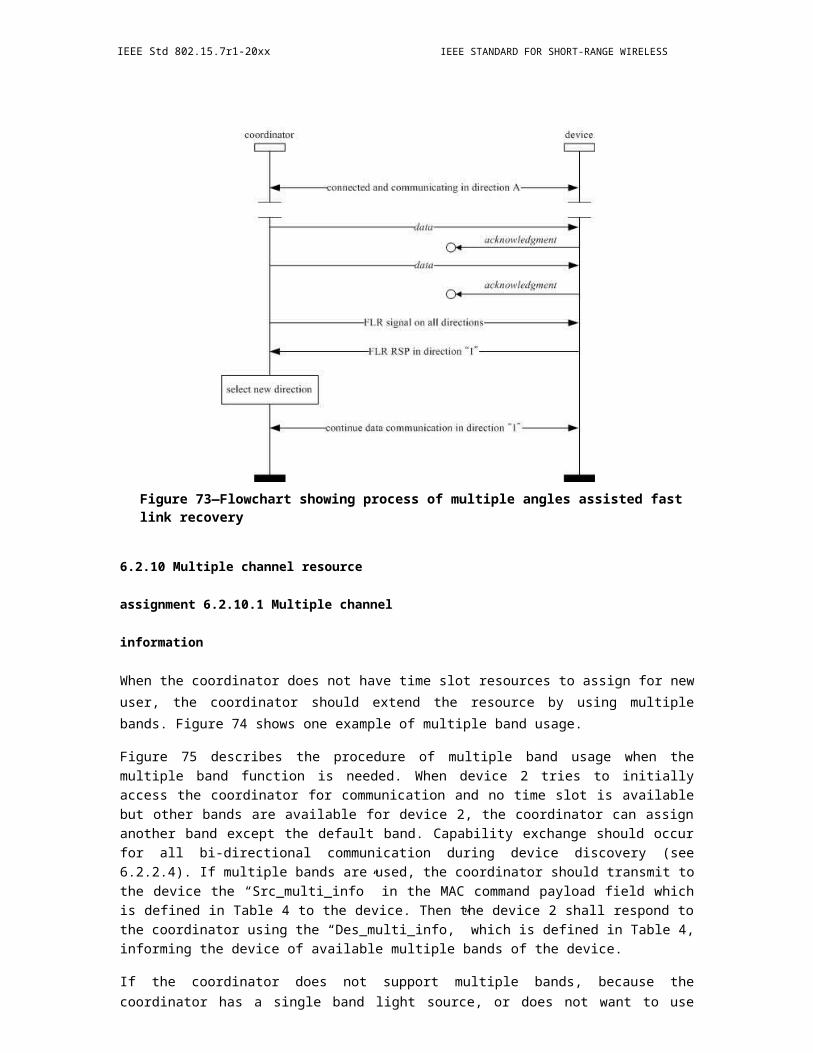
OPTICAL COMMUNICATION IEEE Std 802.15.7r1-20xx
receipt of a GTS request command with a request type indicating a GTS deallocation, the coordinator will acknowledge the frame and deallocates the GTS. The MLME of the coordinator will then issue the MLME-GTS.indication primitive with the appropriate GTS characteristics. If the coordinator does not receive the deallocation request, countermeasures can be applied by the coordinator to ensure consistency is maintained as discussed in 6.2.8.6.
If the MLME of the coordinator receives an MLME-GTS.request primitive indicating deallocation, the coordinator will deallocate the GTS and issue the MLME- GTS.confirm primitive with a status of SUCCESS and a GTSCharacteristics parameter with a characteristics type equal to zero.
If the device receives a beacon frame from its coordinator with a GTS descriptor containing a short address that matches macShortAddress and a start slot equal to zero, the device immediately stops using the GTS. The MLME of the device then notifies the next higher layer of the deallocation by issuing the MLME-GTS.indication primitive with a GTSCharacteristics parameter containing the characteristics of the deallocated GTS.
If any parameter in the MLME-GTS.request primitive is not supported or is out of range, the MLME will issue the MLME-GTS.confirm primitive with a status of INVALID_PARAMETER.
7.3.5.2 MLME-GTS.indication
The MLME-GTS.indication primitive indicates that a GTS has been allocated or that a previously allocated GTS has been deallocated.
The semantics of the MLME-GTS.indication primitive are as follows:
MLME-GTS.indication (DeviceAddress,GTSCharacteristics,SecurityLevel,KeyIdMode,KeySource,KeyIndex)
Table 44 specifies the parameters for the MLME-GTS.indication primitive.
Table 44—MLME-GTS.indication parameters
Name Type Valid range Description
DeviceAddress Device address 0x0000–0xfffd The 16-bit short address of the device thathas been allocated or deallocated a GTS.
GTSCharacteristics GTS Refer to 6.7.13.2 The characteristics of the GTS.characteristics
Copyright © 2011 IEEE. All rights reserved. 229
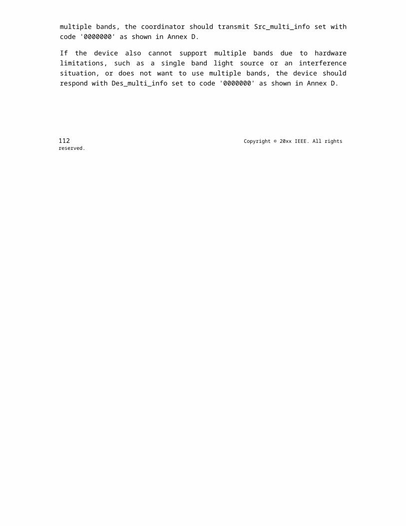
IEEE Std 802.15.7r1-20xx IEEE STANDARD FOR SHORT-RANGE WIRELESS
Table 44—MLME-GTS.indication parameters (continued)
Name Type Valid range Description
SecurityLevel Integer 0x00–0x07 If the primitive was generated when a GTSdeallocation is initiated by the coordinatoritself, the security level to be used is set to0x00.
If the primitive was generated whenever aGTS is allocated or deallocated followingthe reception of a GTS request command:
The security level purportedly used by thereceived MAC command frame (as definedin Table 67 in 8.4.2.1).
KeyIdMode Integer 0x00–0x03 If the primitive was generated when a GTSdeallocation is initiated by the coordinatoritself, this parameter is ignored.
If the primitive was generated whenever aGTS is allocated or deallocated followingthe reception of a GTS request command:
The mode used to identify the keypurportedly used by the originator of thereceived frame (as defined in Table 68 in8.4.2.2). This parameter is invalid if theSecurityLevel parameter is set to 0x00.
KeySource Set of 0, 4, or 8 As specified by the If the primitive was generated when a GTSoctets KeyIdMode parameter deallocation is initiated by the coordinator
itself, this parameter is ignored.
If the primitive was generated whenever aGTS is allocated or deallocated followingthe reception of a GTS request command:
The originator of the key purportedly usedby the originator of the received frame (see8.4.4.1). This parameter is invalid if theKeyIdMode parameter is invalid or set to0x00.
KeyIndex Integer 0x01–0xff If the primitive was generated when a GTSdeallocation is initiated by the coordinatoritself, this parameter is ignored.
If the primitive was generated whenever aGTS is allocated or deallocated followingthe reception of a GTS request command:
The index of the key purportedly used by theoriginator of the received frame (see8.4.4.2). This parameter is invalid if theKeyIdMode parameter is invalid or set to0x00.
230 Copyright © 20xx IEEE. All rights reserved.

OPTICAL COMMUNICATION IEEE Std 802.15.7r1-20xx
7.3.5.2.1 When generated
The MLME -GTS.indication primitive is generated by the MLME of the coordinator to its next higher layer whenever a GTS is allocated or deallocated following the reception of a GTS request command by the MLME as discussed in 6.7.13. The MLME of the coordinator also generates this primitive when a GTS deallocation is initiated by the coordinator itself. The Characteristics Type field in the GTSCharacteristics parameter will be equal to one if a GTS has been allocated or zero if a GTS has been deallocated.
This primitive is generated by the MLME of a device and issued to its next higher layer when the coordinator has deallocated one of its GTSs. In this case, the Characteristics Type field of the GTSCharacteristics parameter is equal to zero.
7.3.5.2.2 Appropriate usage
On receipt of the MLME-GTS.indication primitive the next higher layer is notified of the allocation or de-allocation of a GTS.
7.3.5.3 MLME-GTS.confirm
The MLME-GTS.confirm primitive reports the results of a request to allocate a new GTS or deallocate an existing GTS.
The semantics of the MLME-GTS.confirm primitive are as follows:
MLME-GTS.confirm ( GTSCharacteristics, status
)
Table 45 specifies the parameters for the MLME-GTS.confirm primitive.
Table 45—MLME-GTS.confirm parameters
Name Type Valid range Description
GTSCharacteristics GTS Refer to 6.7.13.2 The characteristics of the GTS.characteristics
status Enumeration SUCCESS, The status of the GTS request.DENIED,NO_SHORT_ADDRESS,CHANNEL_ACCESS_FAILURE,NO_ACK,NO_DATA,COUNTER_ERROR,FRAME_TOO_LONG,UNAVAILABLE_KEY,UNSUPPORTED_SECURITY,INVALID_PARAMETER
7.3.5.3.1 When generated
The MLME- GTS.confirm primitive is generated by the MLME and issued to its next higher layer in response to a previously issued MLME-GTS.request primitive.
Copyright © 2011 IEEE. All rights reserved. 231

IEEE Std 802.15.7r1-20xx IEEE STANDARD FOR SHORT-RANGE WIRELESS
If the request to allocate or deallocate a GTS was successful, this primitive will return a status of SUCCESS and the Characteristics Type field of the GTSCharacteristics parameter will have the value of one or zero, respectively. Otherwise, the status parameter will indicate the appropriate error code. The reasons for these status values are fully described in 7.3.5.1.2 and subclauses referenced by 7.3.5.1.2.
7.3.5.3.2 Appropriate usage
On receipt of the MLME- GTS.confirm primitive the next higher layer is notified of the result of its request to allocate or deallocate a GTS. If the request was successful, the status parameter will indicate a successful GTS operation. Otherwise, the status parameter will indicate the error.
7.3.5.4 GTS management message sequence charts
Figure 151 and Figure 152 illustrate the sequence of messages necessary for successful GTS management. The first depicts the message flow for the case in which the device initiates the GTS allocation. The second depicts the message flow for the two cases for which a GTS deallocation occurs, first, by a device (a) and, second, by the coordinator (b).
Figure 151—Message sequence chart for GTS allocation initiated by a device
7.3.6 Primitives for resetting the MAC sublayer
MLME-SAP reset primitives specify how to reset the MAC sublayer to its default values.
All devices shall provide an interface for these reset primitives.
7.3.6.1 MLME-RESET.request
The MLME-RESET.request primitive allows the next higher layer to request that the MLME performs a reset operation.
232 Copyright © 20xx IEEE. All rights reserved.
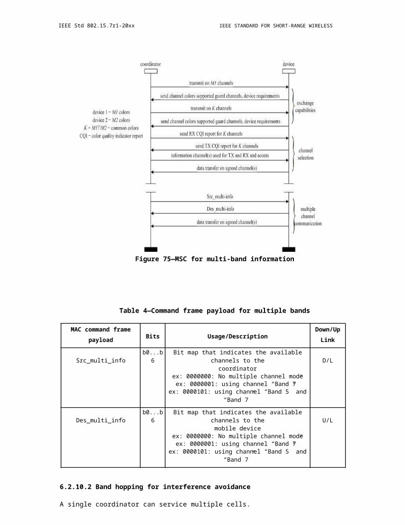
OPTICAL COMMUNICATION IEEE Std 802.15.7r1-20xx
Figure 152—Message sequence chart for GTS deallocation initiated by a device (a) and the PAN coordinator (b)
The semantics of the MLME-RESET.request primitive are as follows:
MLME-RESET.request ( SetDefaultPIB
)
Table 46 specifies the parameter for the MLME-RESET.request primitive.
Table 46—MLME-RESET.request parameter
Name Type Valid range Description
SetDefaultPIB Boolean TRUE or FALSE If TRUE, the MAC sublayer is reset, and all MACPIB attributes are set to their default values. IfFALSE, the MAC sublayer is reset, but all MAC PIBattributes retain their values prior to the generation ofthe MLME-RESET.request primitive.
7.3.6.1.1 Appropriate usage
The MLME-RESET.request primitive is generated by the next higher layer and issued to the MLME to request a reset of the MAC sublayer to its initial conditions. The MLME-RESET.request primitive is issued prior to the use of the MLME-START.request or the MLME-ASSOCIATE.request primitives.
Copyright © 2011 IEEE. All rights reserved. 233

IEEE Std 802.15.7r1-20xx IEEE STANDARD FOR SHORT-RANGE WIRELESS
7.3.6.1.2 Effect on receipt
On receipt of the MLME-RESET.request primitive, the MLME issues the PLME-SET-TRX-STATE.request primitive with a state of FORCE_TRX_OFF. On receipt of the PLME-SET-TRX-STATE.confirm primitive, the MAC sublayer is then set to its initial conditions, clearing all internal variables to their default values. If the SetDefaultPIB parameter is set to TRUE, the MAC PIB attributes are set to their default values.
The MLME-RESET.confirm primitive with a status of SUCCESS is issued on completion.
7.3.6.2 MLME-RESET.confirm
The MLME-RESET.confirm primitive reports the results of the reset operation.
The semantics of the MLME-RESET.confirm primitive are as follows:
MLME-RESET.confirm (status)
Table 47 specifies the parameter for the MLME-RESET.confirm primitive.
Table 47—MLME-RESET.confirm parameter
Name Type Valid range Description
status Enumeration SUCCESS The result of the reset operation.
7.3.6.2.1 When generated
The MLME -RESET.confirm primitive is generated by the MLME and issued to its next higher layer in response to an MLME-RESET.request primitive and following the receipt of the PLME-SET-TRX-STATE.confirm primitive.
7.3.6.2.2 Appropriate usage
On receipt of the MLME-RESET.confirm primitive, the next higher layer is notified of its request to reset the MAC sublayer. This primitive returns a status of SUCCESS indicating that the request to reset the MAC sublayer was successful.
7.3.7 Primitives for specifying the receiver enable time
MLME-SAP receiver state primitives define how a device can enable or disable the receiver at a given time.
These receiver state primitives are optional.
7.3.7.1 MLME-RX-ENABLE.request
The MLME -RX-ENABLE.request primitive allows the next higher layer to request that the receiver is either enabled for a finite period of time or disabled.
234 Copyright © 20xx IEEE. All rights reserved.

OPTICAL COMMUNICATION IEEE Std 802.15.7r1-20xx
The semantics of the MLME-RX-ENABLE.request primitive are as follows:MLME-RX-ENABLE.request ( DeferPermit,
RxOnTime,
RxOnDuration
)
Table 48 specifies the parameters for the MLME-RX-ENABLE.request primitive.
Table 48—MLME-RX-ENABLE.request parameters
Name Type Valid range Description
DeferPermit Boolean TRUE or FALSE TRUE if the requested operation can be deferred untilthe next superframe if the requested time has alreadypassed. FALSE if the requested operation is only to beattempted in the current superframe. This parameter isignored for nonbeacon-enabled VPANs.
If the issuing device is the VPAN coordinator, theterm superframe refers to its own superframe.Otherwise, the term refers to the superframe of thecoordinator through which the issuing device isassociated.
RxOnTime Integer 0x000000–0xffffff The number of optical clocks measured from the startof the superframe before the receiver is to be enabledor disabled. This is a 24-bit value, and the precision ofthis value shall be a minimum of 20 bits, with thelowest 4 bits being the least significant. Thisparameter is ignored for nonbeacon-enabled VPANs.
If the issuing device is the VPAN coordinator, theterm superframe refers to its own superframe.Otherwise, the term refers to the superframe of thecoordinator through which the issuing device isassociated.
RxOnDuration Integer 0x000000–0xffffff The number of optical clocks for which the receiver isto be enabled.
If this parameter is equal to 0x000000, the receiver isto be disabled.
7.3.7.1.1 Appropriate usage
The MLME-RX-ENABLE.request primitive is generated by the next higher layer and issued to the MLME to enable the receiver for a fixed duration, at a time relative to the start of the current or next superframe on a beacon- enabled VPAN or immediately on a nonbeacon-enabled VPAN. This primitive may also be generated to cancel a previously generated request to enable the receiver. The receiver is enabled or disabled exactly once per primitive request.
Copyright © 2011 IEEE. All rights reserved. 235

IEEE Std 802.15.7r1-20xx IEEE STANDARD FOR SHORT-RANGE WIRELESS
7.3.7.1.2 Effect on receipt
The MLME will treat the request to enable or disable the receiver as secondary to other responsibilities of the device (e.g., GTSs, coordinator beacon tracking, beacon transmissions). When the primitive is issued to enable the receiver, the device will enable its receiver until either the device has a conflicting responsibility or the time specified by RxOnDuration has expired. In the case of a conflicting responsibility, the device will interrupt the receive operation. After the completion of the interrupting operation, the RxOnDuration will be checked to determine whether the time has expired. If so, the operation is complete. If not, the receiver is re-enabled until either the device has another conflicting responsibility or the time specified by RxOnDuration has expired. When the primitive is issued to disable the receiver, the device will disable its receiver unless the device has a conflicting responsibility.
On a nonbeacon-enabled VPAN, the MLME ignores the DeferPermit and RxOnTime parameters and requests that the PHY enable or disable the receiver immediately. If the request is to enable the receiver, the receiver will remain enabled until RxOnDuration symbols have elapsed.
Before attempting to enable the receiver on a beacon-enabled VPAN, the MLME first determines whether (RxOnTime + RxOnDuration) is less than the beacon interval, as defined by macBeaconOrder. If (RxOnTime + RxOnDuration) is not less than the beacon interval, the MLME issues the MLME-RX-ENABLE.confirm primitive with a status of ON_TIME_TOO_LONG.
The MLME then determines whether the receiver can be enabled in the current superframe. The VPAN coordinator issuing this primitive makes the determination based on its own superframe. A device that is not the VPAN coordinator makes the determination based on the superframe of the coordinator through which it is associated. If the current number of optical clocks measured from the start of the superframe is less than RxOnTime, the MLME attempts to enable the receiver in the current superframe. If the current number of optical clocks measured from the start of the superframe is greater than or equal to RxOnTime and DeferPermit is equal to TRUE, the MLME defers until the next superframe and attempts to enable the receiver in that superframe. Otherwise, if the MLME cannot enable the receiver in the current superframe and is not permitted to defer the receive operation until the next superframe, the MLME issues the MLME-RX-ENABLE.confirm primitive with a status of PAST_TIME.
If the RxOnDuration parameter is equal to zero, the MLME requests that the PHY disable its receiver.
If any parameter in the MLME-RX-ENABLE.request primitive is not supported or is out of range, the MAC sublayer will issue the MLME-RX-ENABLE.confirm primitive with a status of INVALID_PARAMETER.
If the request to enable or disable the receiver was successful, the MLME issues the MLME-RX-ENABLE.confirm primitive with a status of SUCCESS.
7.3.7.2 MLME-RX-ENABLE.confirm
The MLME-RX-ENABLE.confirm primitive reports the results of the attempt to enable or disable the receiver.
The semantics of the MLME-RX-ENABLE.confirm primitive are as follows:
MLME-RX-ENABLE.confirm (status)
Table 49 specifies the parameter for the MLME-RX-ENABLE.confirm primitive.
236 Copyright © 20xx IEEE. All rights reserved.
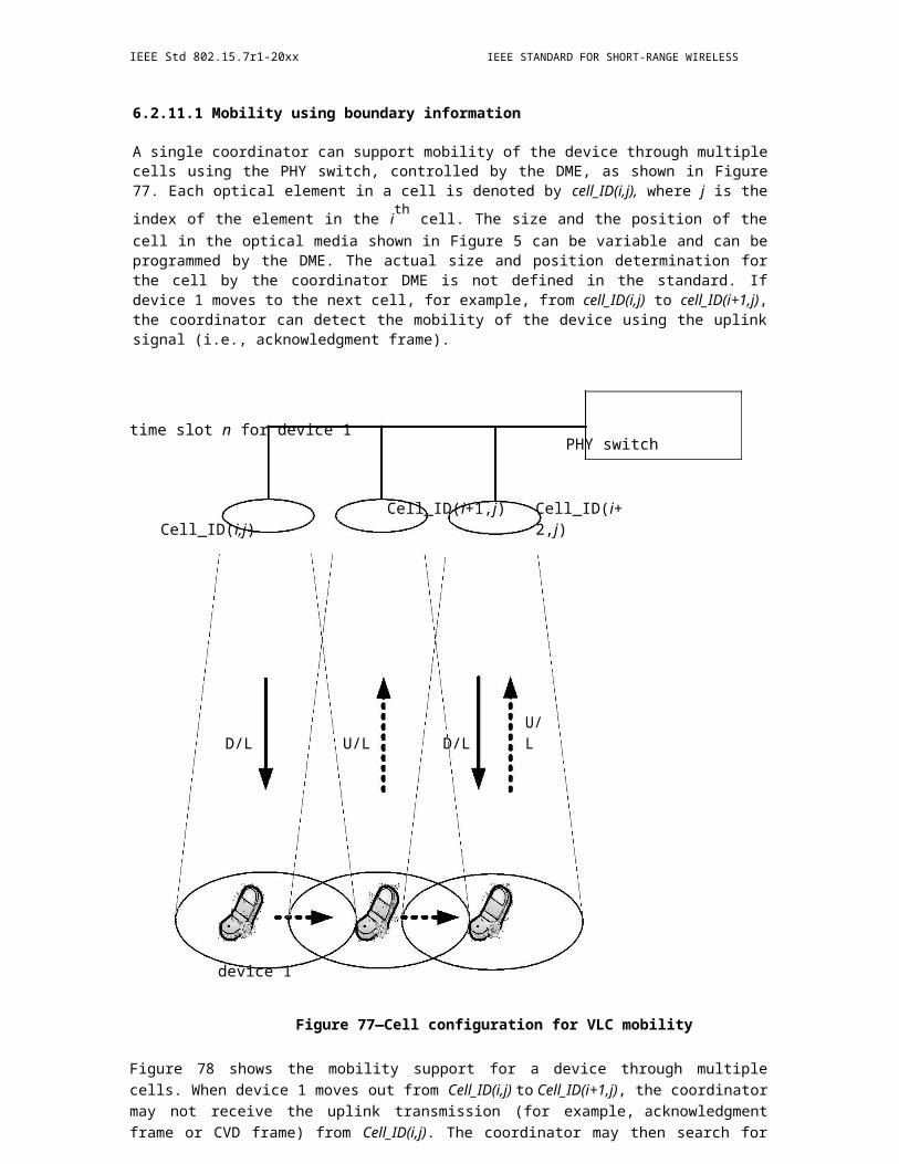
OPTICAL COMMUNICATION IEEE Std 802.15.7r1-20xx
Table 49—MLME-RX-ENABLE.confirm parameter
Name Type Valid range Description
status Enumeration SUCCESS, The result of the request to enable or disable thePAST_TIME, receiver.ON_TIME_TOO_LONG,INVALID_PARAMETER
7.3.7.2.1 When generated
The MLME-RX- ENABLE.confirm primitive is generated by the MLME and issued to its next higher layer in response to an MLME-RX-ENABLE.request primitive.
7.3.7.2.2 Appropriate usage
On receipt of the MLME-RX- ENABLE.confirm primitive, the next higher layer is notified of its request to enable or disable the receiver. This primitive returns a status of either SUCCESS, if the request to enable or disable the receiver was successful, or the appropriate error code. The status values are fully described in 7.3.7.1.2.
7.3.7.3 Message sequence chart for changing the state of the receiver
Figure 153 illustrates the sequence of messages necessary for enabling the receiver for a fixed duration when the device does not have any conflicting responsibilities. Figure 153a) illustrates the case for a beacon-enabled VPAN where it is assumed both that the MLME-RX-ENABLE.request has been received by the MLME without sufficient time available to enable the receiver in the current superframe and that the DeferPermit parameter is TRUE. Figure 153b) illustrates the case for a nonbeacon-enabled VPAN where the receiver is enabled immediately.
7.3.8 Primitives for channel scanning
MLME-SAP scan primitives define how a device can determine the energy usage or the presence or absence of VPANs in a communications channel.
All devices shall provide an interface for these scan primitives.
7.3.8.1 MLME-SCAN.request
The MLME-SCAN.request primitive is used to initiate a channel scan over a given list of channels. A device can use a channel scan to measure the energy on the channel, search for the coordinator with which it associated, or search for all coordinators transmitting beacon frames within the coverage area of the scanning device.
Copyright © 2011 IEEE. All rights reserved. 237
IEEE Std 802.15.7r1-20xx IEEE STANDARD FOR SHORT-RANGE WIRELESS
Figure 153—Message sequence chart for changing the state of the receiver
The semantics of the MLME-SCAN.request primitive are as follows:
MLME-SCAN.request (ScanType,ScanChannels,ScanDuration,SecurityLevel,KeyIdMode,KeySource,KeyIndex,ColorScan)
Table 50 specifies the parameters for the MLME-SCAN.request primitive.
238 Copyright © 20xx IEEE. All rights reserved.
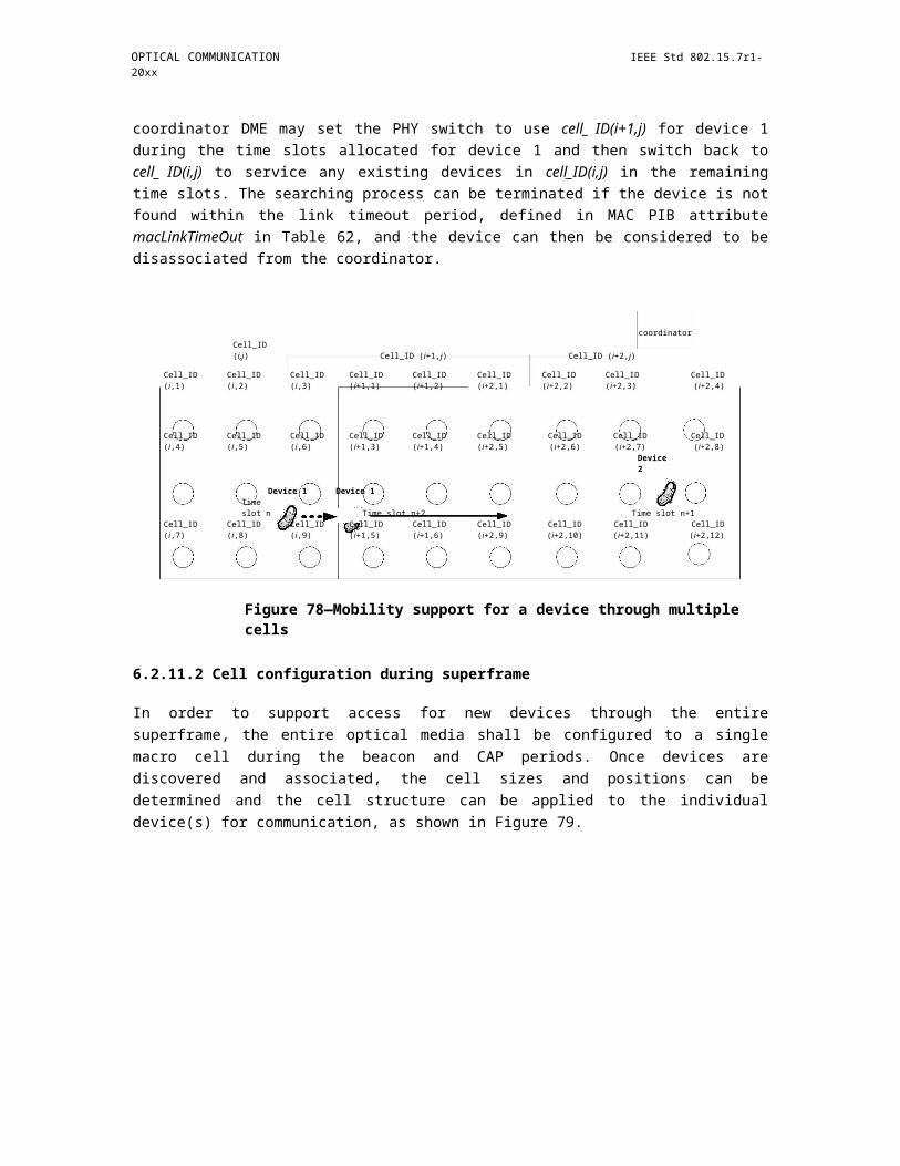
OPTICAL COMMUNICATION IEEE Std 802.15.7r1-20xx
Table 50—MLME-SCAN.request parameters
Name Type Valid range Description
ScanType Integer 0x00–0x01 Indicates the type of scan performed:0x00 = active scan (optional for a device).0x01 = passive scan.
ScanChannels Bitmap 7-bit field The 7 bits (b0, b1,... b6) indicate which channelsare to be scanned (1 = scan, 0 = do not scan).
ScanDuration Integer 0–14 The time spent scanning each channel is[aBaseSuperframeDuration (2n + 1)] opticalclocks, where n is the value of theScanDuration parameter.
SecurityLevel Integer 0x00–0x07 The security level to be used (as defined inTable 67 in 8.4.2.1).
KeyIdMode Integer 0x00–0x03 The mode used to identify the key to be used (asdefined in Table 68 in 8.4.2.2). This parameteris ignored if the SecurityLevel parameter is setto 0x00.
KeySource Set of 0, 4, As specified by the The originator of the key to be used (seeor 8 octets KeyIdMode parameter 8.4.4.1). This parameter is ignored if the
KeyIdMode parameter is ignored or set to 0x00.
KeyIndex Integer 0x01–0xff The index of the key to be used (see 8.4.4.2).This parameter is ignored if the KeyIdModeparameter is ignored or set to 0x00.
ColorScan Boolean TRUE or FALSE ColorScan shall be set as TRUE if the colorCVD frame is to be transmitted either duringpassive scan or after the beacon requestcommand is sent (see 6.2.2.1) for an activescan.
7.3.8.1.1 Appropriate usage
The MLME-SCAN.request primitive is generated by the next higher layer and issued to its MLME to initiate a channel scan to search for activity within the coverage area of the device. This primitive can be used to perform an active or passive scan to locate beacon frames containing any VPAN identifier. Refer to 6.2.3.1 for a description of each type of scan in detail.
All devices shall be capable of performing passive scans, while active scans are optional for a device. However, a device may support active scanning to participate in a nonbeacon-enabled network.
7.3.8.1.2 Effect on receipt
If the MLME receives the MLME-SCAN.request primitive while performing a previously initiated scan operation, it issues the MLME-SCAN.confirm primitive with a status of SCAN_IN_PROGRESS. Otherwise, the MLME initiates a scan in all channels specified in the ScanChannels parameter.
The active scan is performed on each channel by the MLME first sending a beacon request command as specified in 6.7.6. The MLME then enables the receiver and records the information contained in each received beacon in a VPAN descriptor structure as shown in Table 40. The active scan on a particular channel terminates when the number of VPAN descriptors stored equals an implementation-specified
maximum or when [aBaseSuperframeDuration (2n + 1)] optical clocks, where n is the value of the
Copyright © 2011 IEEE. All rights reserved. 239

IEEE Std 802.15.7r1-20xx IEEE STANDARD FOR SHORT-RANGE WIRELESS
ScanDuration parameter, have elapsed, whichever comes first. Refer to 6.2.2.1.1 for more detailed information on the active channel scan procedure.
The passive scan is performed on each channel by the MLME enabling its receiver and recording the information contained in each received beacon in a VPAN descriptor structure as specified in Table 40. The passive scan on a particular channel terminates when the number of VPAN descriptors stored equals an
implementation-specified maximum or when [aBaseSuperframeDuration (2n + 1)] optical clocks, where n is the value of the ScanDuration parameter, have elapsed, whichever comes first. Refer to 6.2.2.1.2 for more detailed information on the passive channel scan procedure.
The scan-over-backhaul is performed on each channel by the MLME first sending a scan-over-backhaul request command to other coordinators through the backhaul as specified in x.x.x. The MLME then enables the receiver and records the information contained in each received scan-over-backhaul confirmation command. The scan-over-backhaul on a particular channel terminates when the number of VPAN descriptors stored equals an implementation-specified maximum or when [aBaseSuperframeDuration (2n
+ 1)] optical clocks, where n is the value of the ScanDuration parameter, have elapsed, whichever comes first. Refer to x.x.x.x.x for more detailed information on the scan-over-backhaul procedure.
If the SecurityLevel parameter is set to a valid value other than 0x00, indicating that security is required for this frame, the MLME will set the Security Enabled subfield of the frame control field to one. The MAC sublayer will perform outgoing processing on the frame based on macCoordExtendedAddress, the SecurityLevel, KeyIdMode, KeySource, and KeyIndex parameters, as described in 8.2.1. If any error occurs during outgoing frame processing, the MLME will discard the frame and issue the MLME-SCAN.confirm primitive with the error status returned by outgoing frame processing.
The results of an active or passive scan are reported to the next higher layer through the MLME-SCAN.confirm primitive. If the scan is successful and macAutoRequest is set to TRUE, the primitive results will include a set of VPAN descriptor values. If the scan is successful and macAutoRequest is set to FALSE, the primitive results will contain a null set of VPAN descriptor values; each VPAN descriptor value will be sent individually to the next higher layer using separate MLME-BEACON-NOTIFY (see 7.3.3.1) primitives. In both cases, the MLME-SCAN.confirm primitive will contain a list of unscanned channels and a status of SUCCESS.
If, during an active scan, the MLME is unable to transmit a beacon request command on a channel specified by the ScanChannels parameter due to a channel access failure, the channel will appear in the list of unscanned channels returned by the MLME-SCAN.confirm primitive. If the MLME was able to send a beacon request command on at least one of the channels but no beacons were found, the MLME-SCAN.confirm primitive will contain a null set of VPAN descriptor values, regardless of the value of macAutoRequest, and a status of NO_BEACON.
If, during an active or passive scan, the implementation-specified maximum is reached thus terminating the scan procedure, the MAC sublayer will issue the MLME-SCAN.confirm primitive with a status ofLIMIT_REACHED.
If any parameter in the MLME-SCAN.request primitive is not supported or is out of range, the MAC sublayer will issue the MLME-SCAN.confirm primitive with a status of INVALID_PARAMETER.
7.3.8.2 MLME-SCAN.confirm
The MLME-SCAN.confirm primitive reports the result of the channel scan request.
The semantics of the MLME-SCAN.confirm primitive are as follows:
MLME-SCAN.confirm (status,ScanType,UnscannedChannels,ResultListSize,VPANDescriptorList

)
240 Copyright © 20xx IEEE. All rights reserved.

OPTICAL COMMUNICATION IEEE Std 802.15.7r1-20xx
Table 51 specifies the parameters for the MLME-SCAN.confirm primitive.
Table 51—MLME-SCAN.confirm parameters
Name Type Valid range Description
status Enumeration SUCCESS, LIMIT_REACHED, The status of the scan request.NO_BEACON,SCAN_IN_PROGRESS,COUNTER_ERROR,FRAME_TOO_LONG,UNAVAILABLE_KEY,UNSUPPORTED_SECURITYor INVALID_PARAMETER
ScanType Integer 0x00–0x01 Indicates the type of scan performed:0x00 = active scan0x01 = passive scan
UnscannedChannels Bitmap 7-bit field Indicates which channels given in therequest were not scanned (1 = notscanned, 0 = scanned or notrequested).
ResultListSize Integer Implementation specific The number of elements returned inthe appropriate result lists.
VPANDescriptorList List of Refer to Table 40 The list of VPAN descriptors, one forVPAN each beacon found during an active ordescriptor passive scan if macAutoRequest is setvalues to TRUE. This parameter is null when
macAutoRequest is set to FALSEduring an active or passive scan.
7.3.8.2.1 When generated
The MLME-SCAN.confirm primitive is generated by the MLME and issued to its next higher layer when the channel scan initiated with the MLME-SCAN.request primitive has completed. If the MLME-SCAN.request primitive requested an active or passive scan with macAutoRequest set to FALSE, the VPANDescriptorList parameter will be null.
The MLME-SCAN.confirm primitive returns a status of either SUCCESS, indicating that the requested scan was successful, or the appropriate error code. The status values are fully described in 7.3.8.1.2 and subclauses referenced by 7.3.8.1.2.
7.3.8.2.2 Appropriate usage
On receipt of the MLME-SCAN.confirm primitive, the next higher layer is notified of the results of the scan procedure. If the requested scan was successful, the status parameter will be set to SUCCESS. Otherwise, the status parameter indicates the error.
7.3.8.3 Channel scan message sequence charts
Figure 166 and Figure 167 illustrate the sequence of messages necessary to perform a passive scan and an active scan. These figures include steps taken by the PHY.
Copyright © 2011 IEEE. All rights reserved. 241

IEEE Std 802.15.7r1-20xx IEEE STANDARD FOR SHORT-RANGE WIRELESS
7.3.9 Communication status primitive
The MLME -SAP communication status primitive defines how the MLME communicates to the next higher layer about transmission status, when the transmission was instigated by a response primitive, and about security errors on incoming packets.
All devices shall provide an interface for this communication status primitive.
7.3.9.1 MLME-COMM-STATUS.indication
The MLME-COMM-STATUS.indication primitive allows the MLME to indicate a communications status.
The semantics of the MLME-COMM-STATUS.indication primitive are as follows:
MLME-COMM-STATUS.indication (VPANId,SrcAddrMode,SrcAddr,DstAddrMode,DstAddr,status,SecurityLevel,KeyIdMode,KeySource,KeyIndex)
Table 52 specifies the parameters for the MLME-COMM-STATUS.indication primitive.
Table 52—MLME-COMM-STATUS.indication parameters
Name Type Valid range Description
VPANId Integer 0x0000–0xffff The 16-bit VPAN identifier of the devicefrom which the frame was received or towhich the frame was being sent.
SrcAddrMode Integer 0x00–0x03 The source addressing mode for thisprimitive. This value can take one of thefollowing values:
0 = no address (addressing fieldsomitted).0x01 = no address field (broadcast onlymode with no address fields present).0x02 = 16-bit short address.0x03 = 64-bit extended address.
SrcAddr Device As specified by the The individual device address of theaddress SrcAddrMode entity from which the frame causing the
parameter error originated.
242 Copyright © 20xx IEEE. All rights reserved.
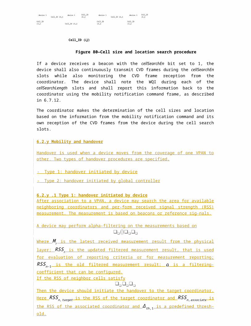
OPTICAL COMMUNICATION IEEE Std 802.15.7r1-20xx
Table 52—MLME-COMM-STATUS.indication parameters (continued)
Name Type Valid range Description
DstAddrMode Integer 0x00–0x03 The destination addressing mode for thisprimitive. This value can take one of thefollowing values:
0x00 = no address (addressing fieldsomitted).0x01 = reserved.0x02 = 16-bit short address.0x03 = 64-bit extended address.
DstAddr Device As specified by the The individual device address of theaddress DstAddrMode device for which the frame was intended.
parameter
status Enumeration SUCCESS, The communications status.TRANSACTION_OVERFLOW,TRANSACTION_EXPIRED,CHANNEL_ACCESS_FAILURE,NO_ACK, COUNTER_ERROR,FRAME_TOO_LONG,IMPROPER_KEY_TYPE,IMPROPER_SECURITY_LEVEL,SECURITY_ERROR,UNAVAILABLE_KEY,UNSUPPORTED_LEGACY,UNSUPPORTED_SECURITY,INVALID_PARAMETER
SecurityLevel Integer 0x00–0x07 If the primitive was generated followinga transmission instigated through aresponse primitive:
The security level to be used (as definedin Table 67 in 8.4.2.1).
If the primitive was generated on receiptof a frame that generates an error in itssecurity processing:
The security level purportedly used bythe received frame (as defined inTable 67 in 8.4.2.1).
Copyright © 2011 IEEE. All rights reserved. 243

IEEE Std 802.15.7r1-20xx IEEE STANDARD FOR SHORT-RANGE WIRELESS
Table 52—MLME-COMM-STATUS.indication parameters (continued)
Name Type Valid range Description
KeyIdMode Integer 0x00–0x03 If the primitive was generated followinga transmission instigated through aresponse primitive:
The mode used to identify the key to beused (as defined in Table 68 in 8.4.2.2).This parameter is ignored if theSecurityLevel parameter is set to 0x00.
If the primitive was generated on receiptof a frame that generates an error in itssecurity processing:
The mode used to identify the keypurportedly used by the originator of thereceived frame (as defined in Table 68 in8.4.2.2). This parameter is invalid if theSecurityLevel parameter is set to 0x00.
KeySource Set of 0, 4, As specified by the KeyIdMode If the primitive was generated followingor 8 octets parameter a transmission instigated through a
response primitive:
The originator of the key to be used (see8.4.4.1). This parameter is ignored if theKeyIdMode parameter is ignored or set to0x00.
If the primitive was generated on receiptof a frame that generates an error in itssecurity processing:
The originator of the key purportedlyused by the originator of the receivedframe (see 8.4.4.1). This parameter isinvalid if the KeyIdMode parameter isinvalid or set to 0x00.
KeyIndex Integer 0x01–0xff If the primitive was generated followinga transmission instigated through aresponse primitive:
The index of the key to be used (see8.4.4.2). This parameter is ignored if theKeyIdMode parameter is ignored or set to0x00.
If the primitive was generated on receiptof a frame that generates an error in itssecurity processing:
The index of the key purportedly used bythe originator of the received frame (see8.4.4.2). This parameter is invalid if theKeyIdMode parameter is invalid or set to0x00.
244 Copyright © 20xx IEEE. All rights reserved.

OPTICAL COMMUNICATION IEEE Std 802.15.7r1-20xx
7.3.9.1.1 When generated
The MLME -COMM-STATUS.indication primitive is generated by the MLME and issued to its next higher layer either following a transmission instigated through a response primitive or on receipt of a frame that generates an error in its security processing (see 8.2.3).
The MLME-COMM-STATUS.indication primitive is generated by the MAC sublayer entity following the MLME-ASSOCIATE.response primitive. This primitive returns a status of either SUCCESS, indicating that the request to transmit was successful, an error code of TRANSACTION_OVERFLOW, TRANSACTION_EXPIRED, CHANNEL_ACCESS_FAILURE, NO_ACK, or INVALID _PARAMETER (these status values are fully described in 7.3.1.3.2), or an error code resulting from failed security processing (these status values are fully described in 8.2.1 and 8.2.3).
7.3.9.1.2 Appropriate usage
On receipt of the MLME -COMM-STATUS.indication primitive, the next higher layer is notified of the communication status of a transmission or notified of an error that has occurred during the secure processing of incoming frame.
7.3.10 Primitives for writing PIB attributes
MLME-SAP set primitives define how PIB attributes may be written.
All devices shall provide an interface for these set primitives.
7.3.10.1 MLME-SET.request
The MLME-SET.request primitive attempts to write the given value to the indicated PIB attribute.
7.3.10.1.1 Semantics of the primitive
The semantics of the MLME-SET.request primitive are as follows:
MLME-SET.request (PIBAttribute,PIBAttributeIndex,PIBAttributeValue)
Table 53 specifies the parameters for the MLME-SET.request primitive.
7.3.10.1.2 Appropriate usage
The MLME-SET.request primitive is generated by the next higher layer and issued to its MLME to write the indicated PIB attribute.
7.3.10.1.3 Effect on receipt
On receipt of the MLME-SET.request primitive, the MLME checks to see if the PIB attribute is a MAC PIB attribute or PHY PIB attribute. If the requested attribute is a MAC attribute, the MLME attempts to write the given value to the indicated MAC PIB attribute in its database. If the PIBAttribute parameter specifies an attribute that is a read- only attribute, shown in Table 62, the MLME will issue the MLME-SET.confirm primitive with a status of READ_ONLY. If the PIBAttribute parameter specifies an attribute that is not found in the database, the MLME will issue the MLME-SET.confirm primitive with a status of
Copyright © 2011 IEEE. All rights reserved. 245

IEEE Std 802.15.7r1-20xx IEEE STANDARD FOR SHORT-RANGE WIRELESS
Table 53—MLME-SET.request parameters
Name Type Valid range Description
PIBAttribute Integer Refer to Table 62 and The identifier of the PIB attribute to write.Table 69
PIBAttributeIndex Integer Attribute specific; The index within the table of the specifiedas defined in Table 62 PIB attribute to write. This parameter is validand Table 69 only for MAC PIB attributes that are tables; it
is ignored when accessing PHY PIBattributes.
PIBAttributeValue Various Attribute specific; The value to write to the indicated PIBas defined in Table 62 attribute.and Table 69
UNSUPPORTED_ATTRIBUTE. If the PIBAttributeIndex parameter specifies an index for a table that is out of range, the MLME will issue the MLME-SET.confirm primitive with a status of INVALID_INDEX. If the PIBAttributeValue parameter specifies a value that is out of the valid range for the given attribute, the MLME will issue the MLME -SET.confirm primitive with a status of INVALID_PARAMETER. If the requested MAC PIB attribute is successfully written, the MLME will issue the MLME-SET.confirm primitive with a status of SUCCESS.
If the PIBAttribute parameter indicates that macBeaconPayloadLength is to be set and the length of the resulting beacon frame exceeds aMaxPHYFrameSize (e.g., due to the additional overhead required for security processing), the MAC sublayer shall not update macBeaconPayloadLength and will issue the MLME-GET.confirm primitive with a status of INVALID_PARAMETER.
If the requested attribute is a PHY PIB attribute, the request is passed to the PHY by issuing the PLME-SET.request primitive. Once the MLME receives the PLME-SET.confirm primitive, it will translate the received status value because the status values used by the PHY are not the same as those used by the MLME (e.g., the status values for SUCCESS are 0x00 and 0x07 in the MAC and PHY enumeration tables, respectively). Following the translation, the MLME will issue the MLME-SET.confirm primitive to the next higher layer with the status parameter resulting from the translation and the PIBAttribute parameter equal to that returned by the PLME primitive.
7.3.10.2 MLME-SET.confirm
The MLME-SET.confirm primitive reports the results of an attempt to write a value to a PIB attribute.
The semantics of the MLME-SET.confirm primitive are as follows:
MLME-SET.confirm (status,PIBAttribute,PIBAttributeIndex)
Table 54 specifies the parameters for the MLME-SET.confirm primitive.
7.3.10.2.1 When generated
The MLME-SET.confirm primitive is generated by the MLME and issued to its next higher layer in response to an MLME-SET.request primitive. The MLME-SET.confirm primitive returns a status of either
246 Copyright © 20xx IEEE. All rights reserved.

OPTICAL COMMUNICATION IEEE Std 802.15.7r1-20xx
Table 54—MLME-SET.confirm parameters
Name Type Valid range Description
status Enumeration SUCCESS, READ_ONLY, The result of the request to write theUNSUPPORTED_ATTRIBUTE, PIB attribute.INVALID_INDEX,INVALID_PARAMETER
PIBAttribute Integer Refer to Table 62 and Table 69 The identifier of the PIB attribute thatwas written.
PIBAttributeIndex Integer Attribute specific; The index within the table of theas defined in Table 62 and specified PIB attribute to write. ThisTable 69 parameter is valid only for MAC PIB
attributes that are tables; it is ignoredwhen accessing PHY PIB attributes.
SUCCESS, indicating that the requested value was written to the indicated PIB attribute, or the appropriate error code. The status values are fully described in 7.3.10.1.3.
7.3.10.2.2 Appropriate usage
On receipt of the MLME-SET.confirm primitive, the next higher layer is notified of the result of its request to set the value of a PIB attribute. If the requested value was written to the indicated PIB attribute, the status parameter will be set to SUCCESS. Otherwise, the status parameter indicates the error.
7.3.11 Primitives for updating the superframe configuration
MLME-SAP start primitives define how a coordinator can request to start using a new superframe configuration in order to initiate a VPAN, begin transmitting beacons on an already existing VPAN, thus facilitating device discovery, or to stop transmitting beacons.
These start primitives are optional for a device.
7.3.11.1 MLME-START.request
The MLME-START.request primitive allows the VLC coordinator to initiate a new VPAN or to begin using a new superframe configuration. This primitive may also be used by a device already associated with an existing VPAN to begin using a new superframe configuration.
Copyright © 2011 IEEE. All rights reserved. 247

IEEE Std 802.15.7r1-20xx IEEE STANDARD FOR SHORT-RANGE WIRELESS
The semantics of the MLME-START.request primitive are as follows:
MLME-START.request (VPANId,LogicalChannel,StartTime,BeaconOrder,SuperframeOrder,VPANCoordinator,CoordRealignment,CoordRealignSecurityLevel,CoordRealignKeyIdMode,CoordRealignKeySource,CoordRealignKeyIndex,BeaconSecurityLevel,BeaconKeyIdMode,BeaconKeySource,BeaconKeyIndex)
Table 55 specifies the parameters for the MLME-START.request primitive.
Table 55—MLME-START.request parameters
Name Type Valid range Description
VPANId Integer 0x0000–0xffff The VPAN identifier to be used bythe device.
LogicalChannel Integer Selected from the available The logical channel on which to startlogical channels using the new superframe
configuration.
StartTime Integer 0x000000–0xffffff The time at which to begintransmitting beacons. If thisparameter is equal to 0x000000,beacon transmissions will beginimmediately. Otherwise, the specifiedtime is relative to the received beaconof the coordinator with which thedevice synchronizes.
This parameter is ignored if either theBeaconOrder parameter has a valueof 15 or the VPANCoordinatorparameter is TRUE.
The time is specified in optical clocksand is rounded to a backoff slotboundary. This is a 24-bit value, andthe precision of this value shall be aminimum of 20 bits, with the lowest4 bits being the least significant.
248 Copyright © 20xx IEEE. All rights reserved.
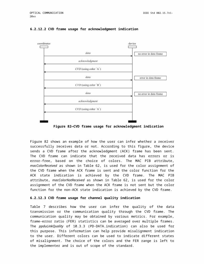
OPTICAL COMMUNICATION IEEE Std 802.15.7r1-20xx
Table 55—MLME-START.request parameters (continued)
Name Type Valid range Description
BeaconOrder Integer 0–15 How often the beacon is to betransmitted. A value of 15 indicatesthat the coordinator will not transmitperiodic beacons.
Refer to 6.2.1.1 for an explanation ofthe relationship between the beaconorder and the beacon interval.
SuperframeOrder Integer 0–BO or 15 The length of the active portion of thesuperframe, including the beaconframe. If the BeaconOrder parameter(BO) has a value of 15, this parameteris ignored.
Refer to 6.2.1.1 for an explanation ofthe relationship between thesuperframe order and the superframeduration.
VPANCoordinator Boolean TRUE or FALSE If this value is TRUE, the device willbecome the coordinator of a newVPAN. If this value is FALSE, thedevice will begin using a newsuperframe configuration on theVPAN with which it is associated.
CoordRealignment Boolean TRUE or FALSE TRUE if a coordinator realignmentcommand is to be transmitted prior tochanging the superframeconfiguration or FALSE otherwise.
CoordRealignSecurity- Integer 0x00–0x07 The security level to be used forLevel coordinator realignment command
frames (as defined in Table 67 in8.4.2.1).
CoordRealignKeyId- Integer 0x00–0x03 The mode used to identify the key toMode be used (as defined in Table 68 in
8.4.2.2). This parameter is ignored ifthe CoordRealignSecurityLevelparameter is set to 0x00.
CoordRealignKey- Set of 0, 4, As specified by the The originator of the key to be usedSource or 8 octets CoordRealignKeyIdMode (see 8.4.4.1). This parameter is
parameter ignored if the CoordRealignKeyId-Mode parameter is ignored or set to0x00.
CoordRealignKeyIndex Integer 0x01–0xff The index of the key to be used (see8.4.4.2). This parameter is ignored ifthe CoordRealignKeyIdModeparameter is ignored or set to 0x00.
BeaconSecurityLevel Integer 0x00–0x07 The security level to be used forbeacon frames (as defined in Table 67in 8.4.2.1).
Copyright © 2011 IEEE. All rights reserved. 249

IEEE Std 802.15.7r1-20xx IEEE STANDARD FOR SHORT-RANGE WIRELESS
Table 55—MLME-START.request parameters (continued)
Name Type Valid range Description
BeaconKeyIdMode Integer 0x00–0x03 The mode used to identify the key tobe used (as defined in Table 68 in8.4.2.2). This parameter is ignored ifthe BeaconSecurityLevel parameter isset to 0x00.
BeaconKeySource Set of 0, 4, As specified by the The originator of the key to be usedor 8 octets BeaconKeyIdMode (see 8.4.4.1). This parameter is
parameter ignored if the BeaconKeyIdModeparameter is ignored or set to 0x00.
BeaconKeyIndex Integer 0x01–0xff The index of the key to be used (see8.4.4.2). This parameter is ignored ifthe BeaconKeyIdMode parameter isignored or set to 0x00.
7.3.11.1.1 Appropriate usage
The MLME-START.request primitive is generated by the next higher layer and issued to its MLME to request that a device start using a new superframe configuration.
7.3.11.1.2 Effect on receipt
If the MLME-START.request primitive is received when macShortAddress is set to 0xffff, the MLME will issue the MLME-START.confirm primitive with a status of NO_SHORT_ADDRESS.
When the CoordRealignment parameter is set to TRUE, the coordinator attempts to transmit a coordinator realignment command frame as described in 6.2.3.3. If the transmission of the coordinator realignment command fails due to a channel access failure, the MLME will not make any changes to the superframe configuration (i.e., no PIB attributes will be changed) and will issue an MLME-START.confirm with a status of CHANNEL_ACCESS_FAILURE. If the coordinator realignment command is successfully transmitted, the MLME updates the appropriate PIB parameters with the values of the BeaconOrder, SuperframeOrder, VPANId, and LogicalChannel parameters, as described in 6.2.3.5, and will issue an MLME-START.confirm with a status of SUCCESS.
When the CoordRealignment parameter is set to FALSE, the MLME updates the appropriate PIB parameters with the values of the BeaconOrder, SuperframeOrder, VPANId, and LogicalChannel parameters, as described in 6.2.3.5.
The address used by the coordinator in its beacon frames is determined by the current value of macShortAddress, which is set by the next higher layer before issuing this primitive.
If the SecurityLevel parameter is set to a valid value other than 0x00, indicating that security is required for this frame, the MLME will set the Security Enabled subfield of the frame control field to one. The MAC sublayer will perform outgoing processing on the frame, as described in 8.2.1. If the CoordRealignment parameter is set to TRUE, the CoordRealignSecurityLevel, CoordRealignKeyIdMode, CoordRealignKey-Source, and CoordRealignKeyIndex parameters will be used to process the MAC command frame. If the BeaconOrder parameter indicates a beacon-enabled network, the BeaconSecurityLevel, BeaconKeyIdMode, BeaconKeySource, and BeaconKeyIndex parameters will be used to process the beacon frame. If any error occurs during outgoing frame processing, the MLME will discard the frame and issue the MLME-START.confirm primitive with the error status returned by outgoing frame processing.
250 Copyright © 20xx IEEE. All rights reserved.

OPTICAL COMMUNICATION IEEE Std 802.15.7r1-20xx
If the length of the beacon frame exceeds aMaxPHYFrameSize (e.g., due to the additional overhead required for security processing), the MAC sublayer shall discard the beacon frame and issue the MLME-START.confirm primitive with a status of FRAME_TOO_LONG.
The MLME shall ignore the StartTime parameter if the BeaconOrder parameter is equal to 15 because this indicates a nonbeacon-enabled VPAN. If the BeaconOrder parameter is less than 15, the MLME examines the StartTime parameter to determine the time to begin transmitting beacons; the time is defined in optical clocks and is rounded to a backoff slot boundary. If the VLC coordinator parameter is set to TRUE, the MLME ignores the StartTime parameter and begins beacon transmissions immediately. Setting the StartTime parameter to 0x000000 also causes the MLME to begin beacon transmissions immediately. If the VPANCoordinator parameter is set to FALSE and the StartTime parameter is nonzero, the MLME calculates the beacon transmission time by adding StartTime optical clocks to the time, obtained from the local clock, when the MLME receives the beacon of the coordinator through which it is associated. If the time calculated causes the outgoing superframe to overlap the incoming superframe, the MLME shall not begin beacon transmissions. In this case, the MLME issues the MLME-START.confirm primitive with a status of SUPERFRAME_OVERLAP. Otherwise, the MLME then begins beacon transmissions when the current time, obtained from the local clock, equals the number of calculated optical clocks.
If the StartTime parameter is nonzero and the MLME is not currently tracking the beacon of the coordinator through which it is associated, the MLME will issue the MLME-START.confirm primitive with a status ofTRACKING_OFF.
On completion of this procedure, the MLME responds with the MLME-START.confirm primitive. If the attempt to start using a new superframe configuration was successful, the status parameter will be set to SUCCESS. If any parameter is not supported or is out of range, the status parameter will be set toINVALID_PARAMETER.
7.3.11.2 MLME-START.confirm
The MLME-START.confirm primitive reports the results of the attempt to start using a new superframe configuration.
The semantics of the MLME-START.confirm primitive are as follows:
MLME-START.confirm (status)
Table 56 specifies the parameters for the MLME-START.confirm primitive.
Table 56—MLME-START.confirm parameters
Name Type Valid range Description
status Enumeration SUCCESS, The result of the attempt to start using an updatedNO_SHORT_ADDRESS, superframe configuration.SUPERFRAME_OVERLAP,TRACKING_OFF,INVALID_PARAMETER,COUNTER_ERROR,FRAME_TOO_LONG,UNAVAILABLE_KEY,UNSUPPORTED_SECURITY,CHANNEL_ACCESS_FAILURE
Copyright © 2011 IEEE. All rights reserved. 251

IEEE Std 802.15.7r1-20xx IEEE STANDARD FOR SHORT-RANGE WIRELESS
7.3.11.2.1 When generated
The MLME-START.confirm primitive is generated by the MLME and issued to its next higher layer in response to an MLME-START.request primitive. The MLME-START.confirm primitive returns a status of either SUCCESS, indicating that the MAC sublayer has started using the new superframe configuration, or the appropriate error code. The status values are fully described in 7.3.11.1.2 and subclauses referenced by 7.3.11.1.2.
7.3.11.2.2 Appropriate usage
On receipt of the MLME-START.confirm primitive, the next higher layer is notified of the result of its request to start using a new superframe configuration. If the MAC sublayer has been successful, the status parameter will be set to SUCCESS. Otherwise, the status parameter indicates the error.
7.3.11.3 Message sequence chart for updating the superframe configuration
Figure 154 illustrates the sequence of messages necessary for initiating beacon transmissions as a coordinator. Figure 163 illustrates the sequence of messages necessary for the VLC coordinator to start beaconing on a new VPAN; this figure includes steps taken by the PHY.
Figure 154—Message sequence chart for updating the superframe configuration
7.3.12 Primitive for synchronizing with a coordinator
MLME-SAP synchronization primitives define how synchronization with a coordinator may be achieved and how a loss of synchronization is communicated to the next higher layer.
All devices shall provide an interface for the indication primitive. The request primitive is optional.
252 Copyright © 20xx IEEE. All rights reserved.

OPTICAL COMMUNICATION IEEE Std 802.15.7r1-20xx
7.3.12.1 MLME-SYNC.request
The MLME-SYNC.request primitive requests to synchronize with the coordinator by acquiring and, if specified, tracking its beacons.
The semantics of the MLME-SYNC.request primitive are as follows:
MLME-SYNC.request ( LogicalChannel, TrackBeacon
)
Table 57 specifies the parameters for the MLME-SYNC.request primitive.
Table 57—MLME-SYNC.request parameters
Name Type Valid range Description
LogicalChannel Integer Selected from the available logical The logical channel on which to attemptchannels supported by the PHY coordinator synchronization.
TrackBeacon Boolean TRUE or FALSE TRUE if the MLME is to synchronize with thenext beacon and attempt to track all futurebeacons. FALSE if the MLME is tosynchronize with only the next beacon.
7.3.12.1.1 Appropriate usage
The MLME-SYNC.request primitive is generated by the next higher layer of a device on a beacon-enabled VPAN and issued to its MLME to synchronize with the coordinator.
7.3.12.1.2 Effect on receipt
If the MLME-SYNC.request primitive is received by the MLME on a beacon-enabled VPAN, it will first set phyCurrentChannel equal to the values of the LogicalChannel parameters, respectively; both attributes are updated by issuing the PLME-SET.request primitive. If the TrackBeacon parameter is equal to TRUE, the MLME will track the beacon, i.e., enable its receiver just before the expected time of each beacon so that the beacon frame can be processed. If the TrackBeacon parameter is equal to FALSE, the MLME will locate the beacon, but not continue to track it.
If this primitive is received by the MLME while it is currently tracking the beacon, the MLME will not discard the primitive, but rather treat it as a new synchronization request.
If the beacon could not be located either on its initial search or during tracking, the MLME will issue the MLME-SYNC-LOSS.indication primitive with a loss reason of BEACON_LOST.
7.3.13 Primitive for synchronization loss with a coordinator
7.3.13.1 MLME-SYNC-LOSS.indication
The MLME-SYNC-LOSS.indication primitive indicates the loss of synchronization with a coordinator.
Copyright © 2011 IEEE. All rights reserved. 253
IEEE Std 802.15.7r1-20xx IEEE STANDARD FOR SHORT-RANGE WIRELESS
The semantics of the MLME-SYNC-LOSS.indication primitive are as follows:
MLME-SYNC-LOSS.indication ( LossReason, VPANId,
LogicalChannel,SecurityLevel,KeyIdMode,KeySource,KeyIndex)
Table 58 specifies the parameters for the MLME-SYNC-LOSS.indication primitive.
Table 58—MLME-SYNC-LOSS.indication parameters
Name Type Valid range Description
LossReason Enumeration VPAN_ID_CONFLICT, The reason that synchronization was lost.REALIGNMENT, orBEACON_LOST
VPANId Integer 0x0000–0xffff The VPAN identifier with which thedevice lost synchronization or to which itwas realigned.
LogicalChannel Integer Selected from the available logical The logical channel on which the devicechannels supported by the PHY lost synchronization or to which it was(see Table 87). realigned.
SecurityLevel Integer 0x00–0x07 If the primitive was either generated bythe device itself following loss ofsynchronization or generated by thecoordinator upon detection of a VPANID conflict, the security level is set to0x00.
If the primitive was generated followingthe reception of either a coordinatorrealignment command or a VPAN IDconflict notification command:
The security level purportedly used bythe received MAC frame (as defined inTable 67 in 8.4.2.1).
254 Copyright © 20xx IEEE. All rights reserved.
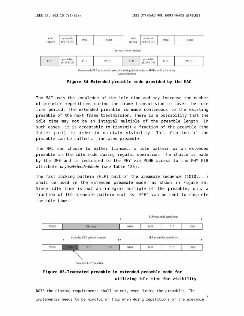
OPTICAL COMMUNICATION IEEE Std 802.15.7r1-20xx
Table 58—MLME-SYNC-LOSS.indication parameters (continued)
Name Type Valid range Description
KeyIdMode Integer 0x00–0x03 If the primitive was either generated bythe device itself following loss ofsynchronization or generated by thecoordinator upon detection of a VPANID conflict, this parameter is ignored.
If the primitive was generated followingthe reception of either a coordinatorrealignment command or a VPAN IDconflict notification command:
The mode used to identify the keypurportedly used by the originator of thereceived frame (as defined in Table 68 in8.4.2.2). This parameter is invalid if theSecurityLevel parameter is set to 0x00.
KeySource Set of 0, 4, or 8 As specified by the KeyIdMode If the primitive was either generated byoctets parameter the device itself following loss of
synchronization or generated by thecoordinator upon detection of a VPANID conflict, this parameter is ignored.
If the primitive was generated followingthe reception of either a coordinatorrealignment command or a VPAN IDconflict notification command:
The originator of the key purportedlyused by the originator of the receivedframe (see 8.4.4.1). This parameter isinvalid if the KeyIdMode parameter isinvalid or set to 0x00.
KeyIndex Integer 0x01–0xff If the primitive was either generated bythe device itself following loss ofsynchronization or generated by thecoordinator upon detection of a VPANID conflict, this parameter is ignored.
If the primitive was generated followingthe reception of either a coordinatorrealignment command or a VPAN IDconflict notification command:
The index of the key purportedly used bythe originator of the received frame (see8.4.4.2). This parameter is invalid if theKeyIdMode parameter is invalid or set to0x00.
7.3.13.2 Message sequence chart for synchronizing with a coordinator
Figure 155 illustrates the sequence of messages necessary for a device to synchronize with a coordinator. In Figure 155a), a single synchronization request is issued. The MLME then searches for a beacon and, if found, determines whether the coordinator has any data pending for the device. If so, the data are requested as described in 6.2.7.3. In Figure 155b), a track synchronization request is issued. The MLME then searches
Copyright © 2011 IEEE. All rights reserved. 255
IEEE Std 802.15.7r1-20xx IEEE STANDARD FOR SHORT-RANGE WIRELESS
for a beacon and, if found, attempts to keep track of it using a timer that expires just before the expected time of the next beacon.
For both examples Figure 155a) and Figure 155b), the received beacon frames do not contain payload, and macAutoRequest is set to TRUE. The MLME also checks for any data pending in the coordinator for the device when a beacon frame is received.
device next device coordinatorhigher layer MLME MLME
a) MLME-SYNC.request(FALSE)single
beacon frame (with data pending)synchronization
request
data request
b) MLME-SYNC.request(TRUE)
beacon
timer to expire tracksynchronization
before the next requestbeacon
beacon
Figure 155—Message sequence chart for synchronizing to a coordinator in a beacon-
7.3.13.2.1 When generated
The MLME -SYNC-LOSS.indication primitive is generated by the MLME of a device and issued to its next higher layer in the event of a loss of synchronization with the coordinator. It is also generated by the MLME of the VLC coordinator and issued to its next higher layer in the event of a VPAN ID conflict.
If a device that is associated through the VLC coordinator has detected a VPAN identifier conflict and communicated it to the VLC coordinator, the MLME will issue this primitive with the LossReason parameter set to VPAN_ID_CONFLICT. Similarly, if the VLC coordinator receives a VPAN ID conflict notification command, as specified in 6.7.5, the MLME will issue this primitive with the LossReason parameter set to VPAN_ID_CONFLICT.
If a device has received the coordinator realignment command, specified in 6.7.7, from the coordinator through which it is associated, the MLME will issue this primitive with the LossReason parameter set to REALIGNMENT and the VPANId, LogicalChannel, and security-related parameters set as described in 6.2.3.4.
256 Copyright © 20xx IEEE. All rights reserved.

OPTICAL COMMUNICATION IEEE Std 802.15.7r1-20xx
If a device has not heard the beacon for aMaxLostBeacons consecutive superframes following an MLME-SYNC.request primitive, either initially or during tracking, the MLME will issue this primitive with the LossReason parameter set to BEACON_LOST. The VPANId, LogicalChannel parameters shall be set according to the coordinator with which synchronization was lost. The SecurityLevel parameter shall be set to zero and the KeyIdMode, KeySource, and KeyIndex parameters shall be ignored. If the beacon was being tracked, the MLME will not attempt to track the beacon any further.
7.3.13.2.2 Appropriate usage
On receipt of the MLME-SYNC-LOSS.indication primitive, the next higher layer is notified of a loss of synchronization.
7.3.14 Primitives for requesting data from a coordinator
MLME-SAP polling primitives define how to request data from a coordinator.
All devices shall provide an interface for these polling primitives.
7.3.14.1 MLME-POLL.request
The MLME-POLL.request primitive prompts the device to request data from the coordinator.
The semantics of the MLME-POLL.request primitive are as follows:
MLME-POLL.request (CoordAddrMode,CoordVPANId,CoordAddress,SecurityLevel,KeyIdMode,KeySource,KeyIndex)
Table 59 specifies the parameter for the MLME-POLL.request primitive.
Table 59—MLME-POLL.request parameters
Name Type Valid range Description
CoordAddrMode Integer 0x02–0x03 The addressing mode of the coordinator towhich the poll is intended. This parameter cantake one of the following values:
2 = 16-bit short address,3 = 64-bit extended address.
CoordVPANId Integer 0x0000–0xfffe The VPAN identifier of the coordinator towhich the poll is intended.
CoordAddress Device- As specified by the The address of the coordinator to which theAddress CoordAddrMode poll is intended.
parameter
Copyright © 2011 IEEE. All rights reserved. 257
IEEE Std 802.15.7r1-20xx IEEE STANDARD FOR SHORT-RANGE WIRELESS
Table 59—MLME-POLL.request parameters (continued)
Name Type Valid range Description
SecurityLevel Integer 0x00–0x07 The security level to be used (as defined inTable 67 in 8.4.2.1).
KeyIdMode Integer 0x00–0x03 The mode used to identify the key to be used(as defined in Table 68 in 8.4.2.2). Thisparameter is ignored if the SecurityLevelparameter is set to 0x00.
KeySource Set of 0, As specified by the The originator of the key to be used (see4, or 8 KeyIdMode parameter 8.4.4.1). This parameter is ignored if theoctets KeyIdMode parameter is ignored or set to
0x00.
KeyIndex Integer 0x01–0xff The index of the key to be used (see 8.4.4.2).This parameter is ignored if the KeyIdModeparameter is ignored or set to 0x00.
7.3.14.1.1 Appropriate usage
The MLME-POLL.request primitive is generated by the next higher layer and issued to its MLME when data are to be requested from a coordinator.
7.3.14.1.2 Effect on receipt
On receipt of the MLME-POLL.request primitive, the MLME generates and sends a data request command, as specified in 6.7.4. If the poll is directed to the coordinator, the data request command may be generated without any destination address information present. Otherwise, the data request command is always generated with the destination address information in the CoordVPANId and CoordAddress parameters.
If the SecurityLevel parameter is set to a valid value other than 0x00, indicating that security is required for this frame, the MLME will set the Security Enabled subfield of the frame control field to one. The MAC sublayer will perform outgoing processing on the frame based on the CoordAddress, SecurityLevel, KeyIdMode, KeySource, and KeyIndex parameters, as described in 8.2.1. If any error occurs during outgoing frame processing, the MLME will discard the frame and issue the MLME-POLL.confirm primitive with the error status returned by outgoing frame processing.
If the data request command cannot be sent due to an unslotted random access algorithm failure, the MLME will issue the MLME-POLL.confirm primitive with a status of CHANNEL_ACCESS_FAILURE.
If the MLME successfully transmits a data request command, the MLME will expect an acknowledgment in return. If an acknowledgment is not received, the MLME will issue the MLME-POLL.confirm primitive with a status of NO_ACK (see 6.2.7.4).
If an acknowledgment is received, the MLME will request that the PHY enable its receiver if the frame pending subfield of the acknowledgment frame is set to one. If the frame pending subfield of the acknowledgment frame is set to zero, the MLME will issue the MLME-POLL.confirm primitive with a status of NO_DATA.
If a frame is received from the coordinator with a zero length payload or if the frame is a MAC command frame, the MLME will issue the MLME-POLL.confirm primitive with a status of NO _DATA. If a frame is received from the coordinator with nonzero length payload, the MLME will issue the MLME-
258 Copyright © 20xx IEEE. All rights reserved.

OPTICAL COMMUNICATION IEEE Std 802.15.7r1-20xx
POLL.confirm primitive with a status of SUCCESS. In this case, the actual data are indicated to the next higher layer using the MCPS-DATA.indication primitive as specified in 7.2.3.
If a frame is not received within macMaxFrameTotalWaitTime CAP optical clocks in a beacon-enabled VPAN, or optical clocks in a nonbeacon-enabled VPAN, even though the acknowledgment to the data request command has its frame pending subfield set to one, the MLME will issue the MLME-POLL.confirm primitive with a status of NO_DATA.
If any parameter in the MLME-POLL.request primitive is not supported or is out of range, the MLME will issue the MLME-POLL.confirm primitive with a status of INVALID_PARAMETER.
7.3.14.2 MLME-POLL.confirm
The MLME-POLL.confirm primitive reports the results of a request to poll the coordinator for data.
The semantics of the MLME-POLL.confirm primitive are as follows:MLME-POLL.confirm (
status)
Table 60 specifies the parameters for the MLME-POLL.confirm primitive.
Table 60—MLME-POLL.confirm parameters
Name Type Valid range Description
status Integer SUCCESS, The status of the data request.CHANNEL_ACCESS_FAILURE,NO_ACK, NO_DATA,COUNTER_ERROR,FRAME_TOO_LONG,UNAVAILABLE_KEY,UNSUPPORTED_SECURITY orINVALID_PARAMETER
7.3.14.2.1 When generated
The MLME-POLL.confirm primitive is generated by the MLME and issued to its next higher layer in response to an MLME-POLL.request primitive. If the request was successful, the status parameter will be equal to SUCCESS, indicating a successful poll for data. Otherwise, the status parameter indicates the appropriate error code. The status values are fully described in 7.3.14.1.2 and the subclauses referenced by 7.3.14.1.2.
7.3.14.2.2 Appropriate usage
On receipt of the MLME-POLL.confirm primitive, the next higher layer is notified of the status of the procedure to request data from the coordinator.
7.3.14.3 Message sequence chart for requesting data from a coordinator
Figure 156 illustrates the sequence of messages necessary, including the layer behavior of the device and the over-the-air interface, for a device to request data from a coordinator.
Copyright © 2011 IEEE. All rights reserved. 259

IEEE Std 802.15.7r1-20xx IEEE STANDARD FOR SHORT-RANGE WIRELESS
In both scenarios Figure 156a) and Figure 156b), a poll request is issued to the MLME, which then sends a data request command to the coordinator. In Figure 156a), the corresponding acknowledgment has the frame pending (FP) subfield set to zero and the MLME issues the poll request confirmation immediately. In Figure 156b), the corresponding acknowledgment has the frame pending subfield set to one and the MLME enables the receiver in anticipation of the data frame from the coordinator. On receipt of this data frame, the MLME issues a poll request confirmation followed by a data indication containing the data of the received frame.
Figure 156—Message sequence chart for requesting data from a coordinator
7.4 Huawei MAC primitives
7.4.1 Primitives for data service
7.4.1.1 MCPS-DATA.request
The MCPS-DATA.request primitive requests the transfer of a MSDU from a local next higher layer entity to a peer next higher layer entity (or entities).
The semantics of the MCPS-DATA.request primitive are as follows:
MCPS-DATA.request (
DstAddr
DstVPANId
MSDULength
MSDU
260 Copyright © 20xx IEEE. All rights reserved.
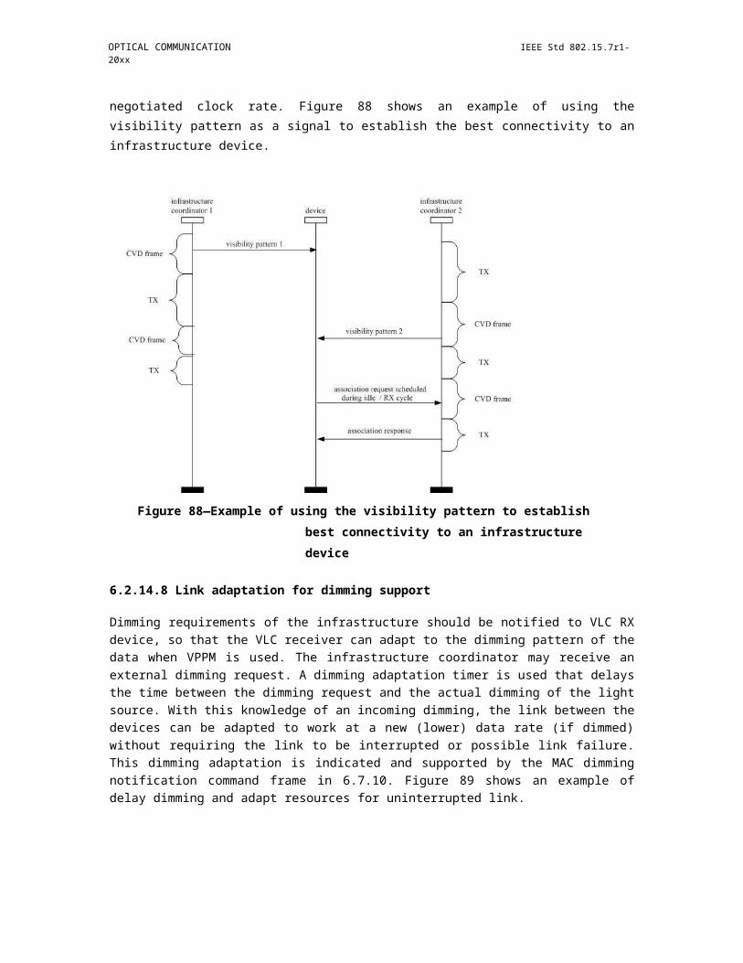
OPTICAL COMMUNICATION IEEE Std 802.15.7r1-20xx
MSDUHandle
TxOptions
)
Table 10 1 specifies the parameters for the MCPS-DATA.request primitive.
Insert Table 10 1 MCPS-DATA.request parameters here 16/360r0
7.4.1.1.1 When generated
The MCPS-DATA.request shall be generated by the next higher layer entity and issued to the MAC sublayer when the next higher layer entity has a MSDU needed to be transmitted to the peer next higher layer entity.
7.4.1.1.2 Effect on receipt
On receipt of the MCPS-DATA.request primitive, the MAC sublayer entity begins the transmission of the supplied MSDU.
The MAC sublayer shall build a MAC frame to transmit from the supplied arguments. The DstAddr, DstVPANId, MSDULength, and b0 of the TxOption fields are used to construct the MAC frame header. The MSDU are used to construct the payload of the MAC frame. The b1 of the TxOptions indicates whether a contention-free transmission is expected or a contention transmission is expected. If a contention-free transmission is expected and a flow between the device and the peer device is already existed, then the MAC sublayer shall defer the transmission until the GTS for the flow begins, and if a flow between the device and the peer device is not existed, then the MAC sublayer shall start the flow establishment procedure so as to obtain GTSs for the transmission of the MAC frame. If the b1 of the TxOptions indicates a contention transmission, then the device shall start the random access procedure in the CAP of the superframe.
7.4.1.2 MCPS-DATA.confirm
The MCPS- DATA.confirm primitive reports the results of a request to transfer a MSDU from a local next higher layer entity to a peer next higher layer entity.
The semantics of the MCPS-DATA.confirm primitive are as follows:
MCPS-DATA.confirm(
MSDUHandle
Status
Timestamp
)
Table 10 2 specifies the parameters for the MCPS-DATA.confirm primitive.
Insert Table 10 2 MCPS-DATA.confirm primitive here
The time at which the MSDU were transmitted. This parameter is valid only if the value of the status parameter is SUCCESS.
Copyright © 2011 IEEE. All rights reserved. 261

IEEE Std 802.15.7r1-20xx IEEE STANDARD FOR SHORT-RANGE WIRELESS
7.4.1.2.1 When generated
The MCPS-DATA.confirm primitive is generated by the MAC sublayer entity in response to an MCPS-DATA.request primitive. The MCPS-DATA.confirm primitive returns a status of either SUCCESS, indicating that the requested transmission was successful or the appropriate error codes.
7.4.1.2.2 Effect on receipt
On receipt of the MCPS-DATA.confirm primitive, the local next higher layer of the device is notified of the result of its request to transmit based on the status value.
7.4.1.3 MCPS-DATA.indication
The MCPS-DATA.indication primitive indicates the transfer of a MSDU from the MAC sublayer to the local next higher layer entity.
The semantics of the MCPS-DATA.indication primitive are as follows:
MCPS-DATA.indication(
SrcAddr
SrcVPANId
DstAddr
DstVPANId
MSDULength
MSDU
MSDUHandle
DSN
Timestamp
)
Table 10 3 specifies the parameters for the MCPS-DATA.indication primitive.
Insert Table 10 3 MCPS-DATA.indication parameters here
7.4.1.3.1 When generated
The MCPS-DATA.indication primitive is generated by the MAC sublayer and issued to the next higher layer on receipt of a data frame at the local MAC sublayer entity that passes the appropriate message filtering operation.
7.4.1.3.2 Effect on receipt
The next higher layer is notified of the MSDU on receipt of the MCPS-DATA.indication primitive and shall process the MSDU accordingly.
262 Copyright © 20xx IEEE. All rights reserved.
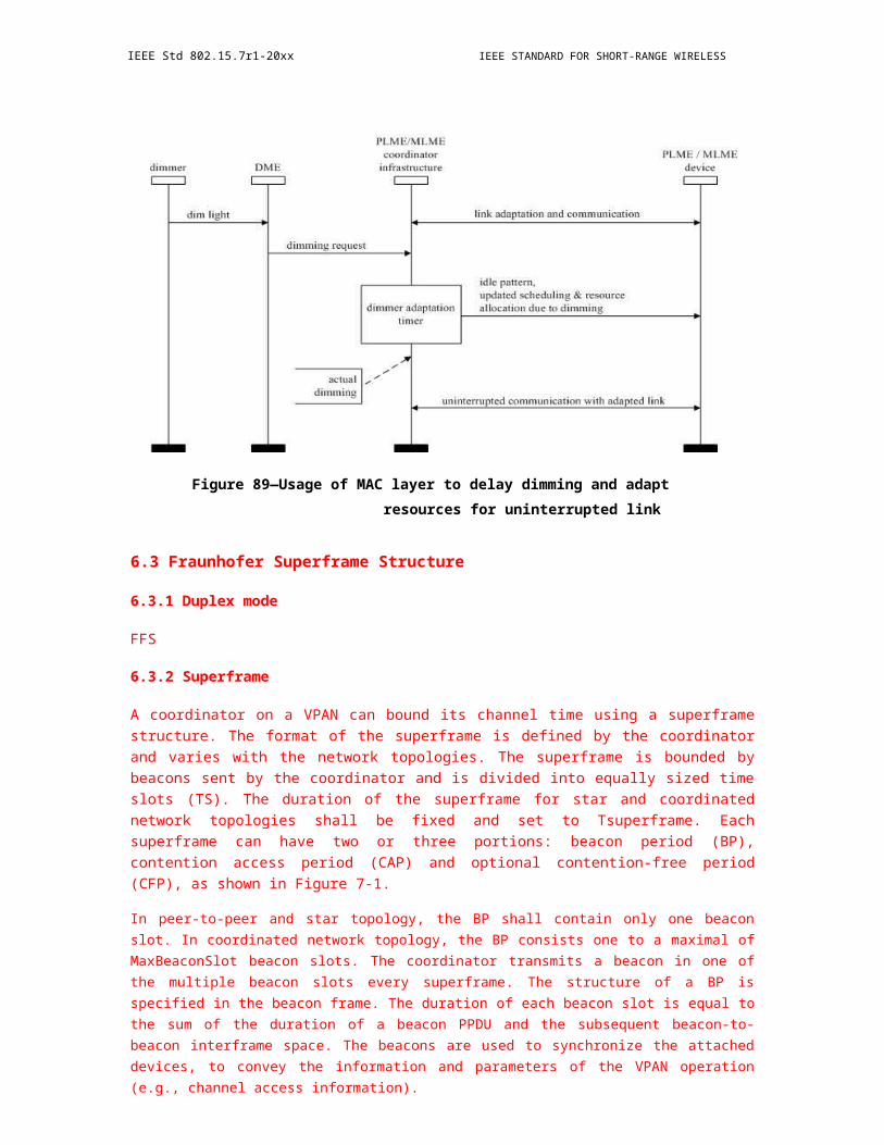
OPTICAL COMMUNICATION IEEE Std 802.15.7r1-20xx
7.4.1.4 Primitives for a heterogeneous network
As described in 1.2, ACK frames from type 2 devices to a coordinator shall be send trough RF link first and then relayed to the coordinator through a wired backhaul link (power line, Ethernet, cable, etc.) in a heterogeneous network, which is a different way than it is sent through the VLC link. Therefore, particular primitives are needed so as to send the ACK frame successfully through the RF link and backhaul link.
MCPS- SAP ACK primitives defines how an ACK frame shall be transmitted in a heterogeneous network when a type 2 device has an ACK frame that needs to be sent to the coordinator by the RF link and the backhaul link. For ACK frames sent by type 1 devices and type 3 devices, MCPS-SAP DATA primitives shall be used.
7.4.1.4.1 MCPS-ACK.indication
The MCPS-ACK.indication primitive allows the MAC sublayer of the device to provide an ACK frame to its next higher layer.
The semantics of the MCPS-ACK.indication primitive are as follows:
MCPS-ACK.indication(
DstAddr
SrcAddr
ACKFrame
)
Table 10 4 specifies the parameters for the MCPS-ACK.indication primitive.
Insert Table 10 4 MCPS-ACK.indication primitive here
7.4.1.4.2 When generated
When the MAC sublayer of the device generates an ACK frame that needs to be sent to the coordinator, it shall generate a MCPS-ACK.indication primitive and issue the MCPS-ACK.indication primitive to its next higher layer.
7.4.1.4.3 Effect on receipt
On receipt of the MCPS-ACK.indication primitive, the next higher layer of the device may generate a next higher layer message based on the provided arguments and send it to the next higher layer of the coordinator through the RF link and backhaul link. The ACK frame generated by the MAC sublayer shall be embedded in the next higher layer message.
7.4.1.4.4 MCPS-ACK.request
The MCPS -ACK.request primitive allows the next higher layer of the coordinator to request its MAC sublayer to process an ACK frame received through the backhaul link.
The semantics of the MCPS-ACK.request primitive are as follows:
MCPS-ACK.request(
Copyright © 2011 IEEE. All rights reserved. 263
IEEE Std 802.15.7r1-20xx IEEE STANDARD FOR SHORT-RANGE WIRELESS
DstAddr
SrcAddr
ACKFrame
)
Table 10 5 specifies the parameters for the MCPS-ACK. request primitive.
Insert Table 10 5 MCPS-ACK. request primitive here
7.4.1.4.5 When generated
The next higher layer of the coordinator shall generate a MCPS-ACK.request primitive when it has received the next higher layer message through the backhaul link and issue the MCPS-ACK.request primitive to its MAC sublayer.
7.4.1.4.6 Effect on receipt
On receipt of the MCPS-ACK.request primitive, the MAC sublayer of the coordinator shall process the ACK frame provided in this primitive the same way as it was received through the VLC link.
7.4.2 Primitives for management service
The MLME- SAP allows the transport of management commands between the next higher layer and the MLME. This subclause shall describe different primitives supported in the MLME-SAP.
7.4.2.1 Association primitives
MLME-SAP association primitives define how a device becomes associated with a VPAN.
7.4.2.1.1 MLME-ASSOCIATE.request
The MLME-ASSOCIATE.request primitive allows a device to request an association with a coordinator.
The semantics of the MLME-ASSOCIATE.request primitive are as follows:
MLME-ASSOCIATE.request(
LogicalChannel
DeviceAddr
CoordAddr
VPANId
CapabilityInformation
)
Table 10 6 specifies the parameters for the MLME-ASSOCIATE.request primitive.
264 Copyright © 20xx IEEE. All rights reserved.
OPTICAL COMMUNICATION IEEE Std 802.15.7r1-20xx
Insert Table 10 6 MLME-ASSOCIATE.request primitive here
7.4.2.1.2 When generated
The MLME-ASSOCIATE.request primitive is generated by the next higher layer of an unassociated device and issued to request an association with a VPAN through a coordinator.
7.4.2.1.3 Effect on receipt
On receipt of the MLME-ASSOCIATE.request primitive, the MLME of an unassociated device first updates the appropriate PHY and MAC MIB attributes and then generate an association request command and send it to the coordinator of the target VPAN specified by the VPANId value.
7.4.2.1.4 MLME-ASSOCIATE.indication
The MLME-ASSOCIATE.indication primitive is used to indicate the reception of an association request command.
The semantics of the MLME-ASSOCIATE.indication primitive are as follows:
MLME-ASSOCIATE.indication(
DeviceAddress
CapabilityInformation
)
Table 10 7 specifies the parameters for the MLME-ASSOCIATE.indication primitive.
Insert Table 10 7 MLME-ASSOCIATE.indication primitive here
7.4.2.1.5 When generated
The MLME-ASSOCIATE.indication primitive is generated by the MLME of the coordinator and issued to its next higher layer to indicate the reception of an association request command received by the PHY.
7.4.2.1.6 Effect on receipt
On receipt of the MLME -ASSOCIATE.indication primitive, the next higher layer of the coordinator is notified of the association request of the device and its capability information. The next higher layer shall then decide whether to accept or reject the association request of the device and provide the decision to the MLME by issuing a MLME-ASSOCIATE.response primitive.
7.4.2.1.7 MLME-ASSOCIATION.response
The MLME-ASSOCIATION.response primitive is used to initiate a response to an MLME-ASSOCIATE.indication primitive.
The semantics of the MLME-ASSOCIATE.response primitive are as follows:
MLME-ASSOCIATE.response(
DeviceAddr
Copyright © 2011 IEEE. All rights reserved. 265

IEEE Std 802.15.7r1-20xx IEEE STANDARD FOR SHORT-RANGE WIRELESS
Status
CapabilityNegotiationResponse
)
Table 10 8 specifies the parameters for the MLME-ASSOCIATE.response primitive.
Insert Table 10 8 MLME-ASSOCIATE.response primitive here
When generated
The MLME -ASSOCIATE.response primitive is generated by the next higher layer of a coordinator and issued to its MLME in order to respond the MLME-ASSOCIATE.indication primitive.
Effect on receipt
On receipt of the MLME-ASSOCIATE.response primitive, the MLME of the coordinator shall generate an association response command based on the provided arguments and send the command to the device requesting association. The status value shall indicate the MLME whether the association attempt is accepted or rejected. If the status value indicates acceptance of the association request, then a valid short address ranged from 0x0001-0xfffe shall be provide in the primitive, too.
7.4.2.1.8 MLME-ASSOCIATE.confirm
The MLME-ASSOCIATE.confirm primitive is used to inform the next higher layer of the initiating device whether its request to associate was successful or unsuccessful.
The semantics of the MLME-ASSOCIATE.confirm primitive are as follows:
MLME-ASSOCIATE.confirm (
DeviceAddr
Status
CapabilityNegotiationResponse
)
Table 10 9 specifies the parameters for the MLME-ASSOCIATE.confirm primitive.
Insert Table 10 9 MLME-ASSOCIATE.confirm primitive here
When generated
The MLME-ASSOCIATE.confirm primitive is generated by the MLME of initiating device and issued to its next higher layer in response to an MLME-ASSOCIATE.request primitive. If the request was successful, the status parameter will indicate a successful association, as contained in the status field of the association response command.
Effect on receipt
266 Copyright © 20xx IEEE. All rights reserved.
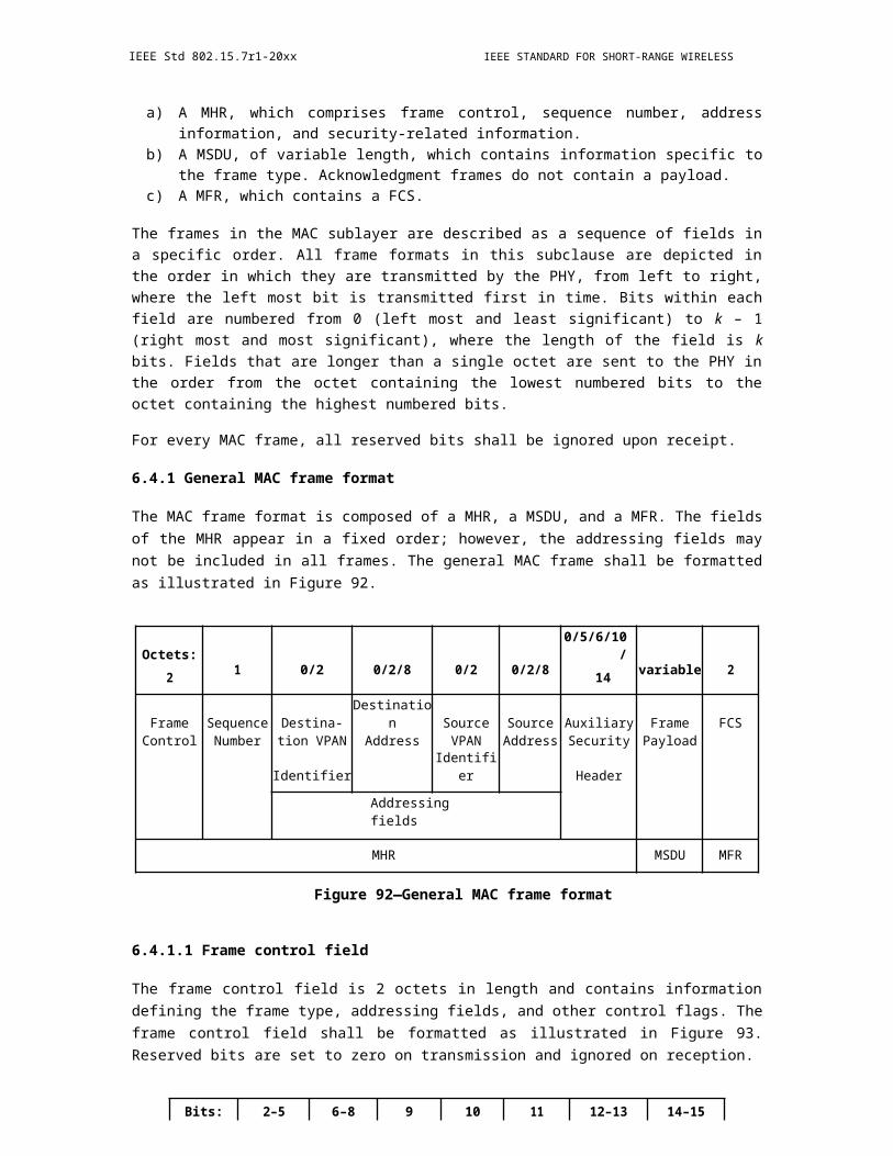
OPTICAL COMMUNICATION IEEE Std 802.15.7r1-20xx
On receipt of the MLME- ASSOCIATE.confirm primitive, the next higher layer of the initiating device is notified of the result of its request to associate with a coordinator. If the association attempt was successful, the status parameter will indicate a successful association, as contained in the status field of the association response command, and the device will be provided with a valid 16 -bit short address. If the association attempt was unsuccessful, the valid short address will not be provided and the error codes will be provided. The next higher layer of the associating device shall not initiate another association attempt if the error has not been properly corrected.
7.4.2.2 Disassociation primitives
The MLME-SAP disassociation primitives define how a device can disassociate from a VPAN.
7.4.2.2.1 MLME-DISASSOCIATE.request
The MLME -DISASSOCIATE.request primitive is used by an associated device to notify the coordinator of its intent to leave the VPAN. It is also used by the coordinator to instruct an associated device to leave the VPAN.
The semantics of the MLME-DISASSOCIATE.request primitive are as follows:
MLME-DISASSOCIATE.request(
DeviceAddr
DisassociationReason
)
Table 10 10 specifies the parameters for the MLME-DISASSOCIATE.request primitive.
Insert Table 10 10 MLME-DISASSOCIATE.request primitive here
When generated
The MLME -DISASSOCIATE.request primitive is generated by the next higher layer of an associated device and issue to its MLME to request disassociation from the VPAN. It is also generated by the next higher layer of the coordinator and issued to its MLME to instruct an associated device to leave the VPAN.
Effect on receipt
On receipt of the MLME-DISASSOCIATE.request primitive, the MLME of the device or the coordinator shall generate a disassociation notification command and send it to the coordinator or the device.
7.4.2.2.2 MLME-DISASSOCIATE.indication
The MLME-DISASSOCIATE.indication primitive is used to indicate the reception of a disassociation notification command.
The semantics of the MLME-DISASSOCIATE.indication primitive are as follows:
MLME-DISASSOCIATE.indication(
DeviceAddr
Copyright © 2011 IEEE. All rights reserved. 267
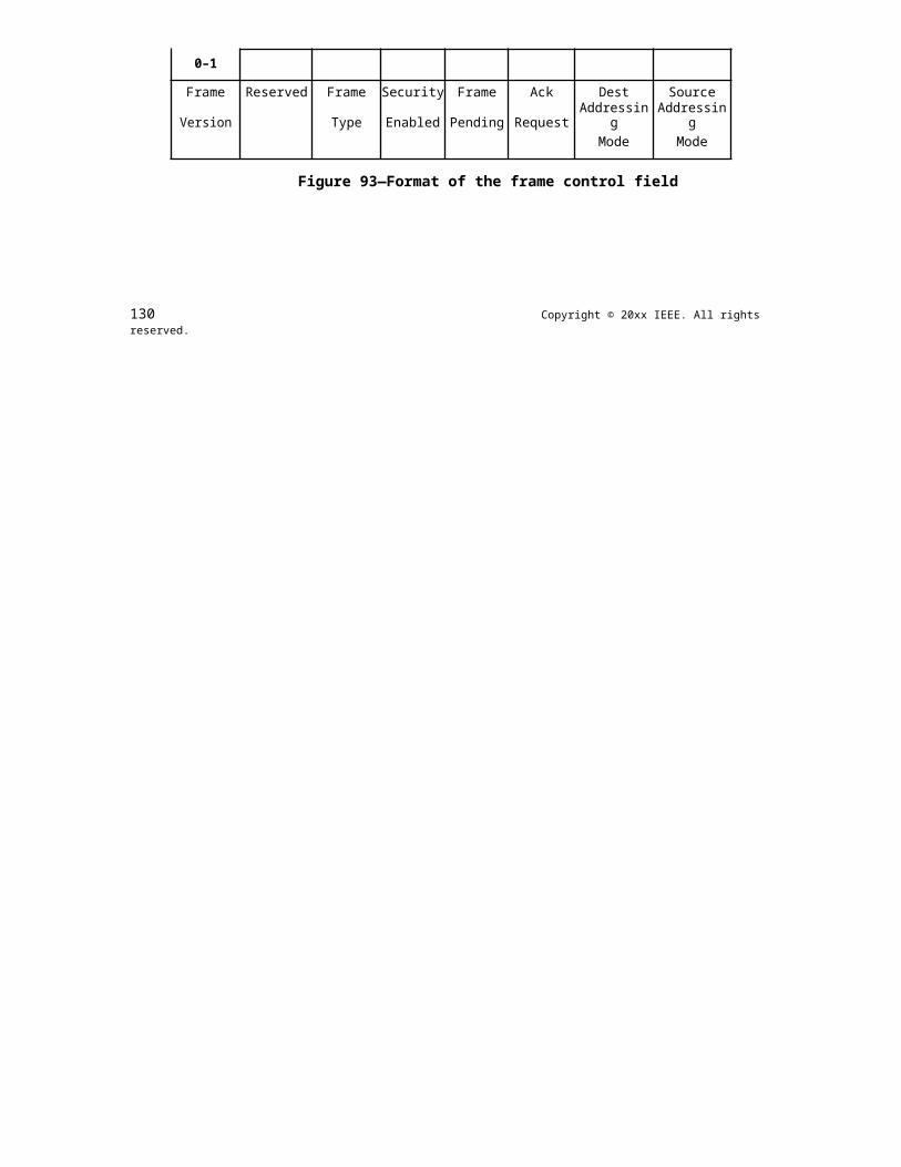
IEEE Std 802.15.7r1-20xx IEEE STANDARD FOR SHORT-RANGE WIRELESS
DisassociationReason
)
Table 10 11 specifies the parameters for the MLME-DISASSOCIATE.indication primitive.
Insert Table 10 11 MLME-DISASSOCIATE.indication primitive here
When generated
The MLME-DISASSOCIATE.indication primitive is generated by the MLME and issued to its next higher layer on receipt of a disassociation notification command.
Effect on receipt
The next higher layer is notified of the reason for the disassociation.
7.4.2.2.3 MLME-DISASSOCIATE.confirm
The MLME-DISASSOCIATE.confirm primitive reports the results of an MLME-DISASSOCIATE.request primitive.
The semantics of the MLME-DISASSOCIATE.confirm primitive are as follows:
MLME-DISASSOCIATE.confirm (
DeviceAddr
Status
)
Table 10 12 specifies the parameters for the MLME-DISASSOCIATE.confirm primitive.
Insert Table 10 12 MLME-DISASSOCIATE.confirm primitive here
When generated
The MLME-DISASSOCIATE.confirm primitive is generated by the initiating MLME and issued to its next higher layer in response to an MLME-DISASSOCIATE.request primitive. This primitive returns a status of either SUCCESS, indicating that the disassociation request was successful, or the appropriate error code.
Effect on receipt
On receipt of the MLME -DISASSOCIATE.confirm primitive, the next higher layer of the initiating device is notified of the result of the disassociation attempt.
7.4.2.3 Scan primitives
MLME-SAP scan primitives define how a device or a coordinator can determine the presence or absence of VPANs in its vicinity.
268 Copyright © 20xx IEEE. All rights reserved.

OPTICAL COMMUNICATION IEEE Std 802.15.7r1-20xx
7.4.2.3.1 MLME-SCAN.request
The MLME-SCAN.request primitive is used to initiate a scan. A device or a coordinator can use the scan to search for other coordinators which transmits beacon frames within the coverage of the scanning device.
The semantics of the MLME-SCAN.request primitive are as follows:
MLME-SCAN.request(
ScanType
ScanDuration
)
Table 10 13 specifies the parameters for the MLME-SCAN.request primitive.
Insert Table 10 13 MLME-SCAN.request primitive here
When generated
The MLME-SCAN.request primitive is issued to the MLME by the next higher when a device needs to associate with a coordinator, or when a device has been requested by the coordinator to perform an active scan, or when a prospective coordinator plans to establish a VPAN.
Effect on receipt
On receipt of the MLME-SCAN.request primitive, the MLME shall initiate the scan accordingly based on the scan type. If a passive scan is requested, then the MLME shall set a timer and enable its receiver to receive beacon frames. If a scan-over-backhaul is requested, then the MLME shall generate a scan- over-backhaul request command and send it to other coordinators through the backhaul. Then the MLME shall wait for other coordinators' scan-over-backhaul confirmation command for ScanDuration. If an active scan is requested, the MLME shall generate a beacon request command and broadcast it. Then the MLME shall wait for other coordinators' beacon frames for ScanDuration. The details of each type of scanning are specified in 8.2.2.1.
7.4.2.3.2 MLME-SCAN.confirm
The MLME-SCAN.confirm primitive reports the result of the scan request.
The semantics of the MLME-SCAN.confirm primitive are as follows:
MLME-SCAN.confirm(
Status
ScanType
ResultListSize
VPANDescriptorList
)
Copyright © 2011 IEEE. All rights reserved. 269
IEEE Std 802.15.7r1-20xx IEEE STANDARD FOR SHORT-RANGE WIRELESS
Table 10 14 specifies the parameters for the MLME-SCAN.confirm primitive.
Insert Table 10 14 MLME-SCAN.confirm primitive here
When generated
The MLME-SCAN.confirm primitive is issued to the next higher layer by the MLME when the requested scan has been completed. The MLME-SCAN.confirm primitive returns a status of either SUCCESS, indicating that the requested scan was successful, or the appropriate error code.
Effect on receipt
On receipt of the MLME-SCAN.confirm primitive, the next higher layer is notified of the results of the scan procedure. If the requested scan was successful, the status parameter will be set to SUCCESS and the next higher layer can proceed accordingly based on the scan type. If the requested scan was unsuccessful, the status parameter indicates the error.
7.4.2.4 Additional Beacon primitives
MLME-SAP additional beacon primitive defines how an unassociated device request coordinators to send additional beacons before initiating an association with a VPAN.
7.4.2.4.1 MLME-AdditionalBeacon.request
The MLME-AdditionalBeacon.request primitive allows an unassociated device to generate and transmit an additional beacon frame request command.
The semantics of the MLME-AdditionalBeacon.request primitive are as follows:
MLME-AdditionalBeacon.request (
Reason
)
Table 10 15 specifies the parameters for the MLME-AdditionalBeacon.request primitive.
Insert Table 10 15 MLME-AdditionalBeacon.request primitive here
When generated
The MLME- AdditionalBeacon.request primitive is generated by the next higher layer of an unassociated device when the next higher layer of the unassociated device has obtained the result of a requested passive scan which indicates no beacon frames has been detected.
Effect on receipt
The MLME of the unassociated device shall generate and transmit an additional beacon request command, then it shall set a timer and enable its receiver to receive beacon frames.
7.4.2.4.2 MLME-AdditionalBeacon.indication
The MLME-AdditionalBeacon.indication primitive is used to indicate the reception of an additional beacon request command.
270 Copyright © 20xx IEEE. All rights reserved.
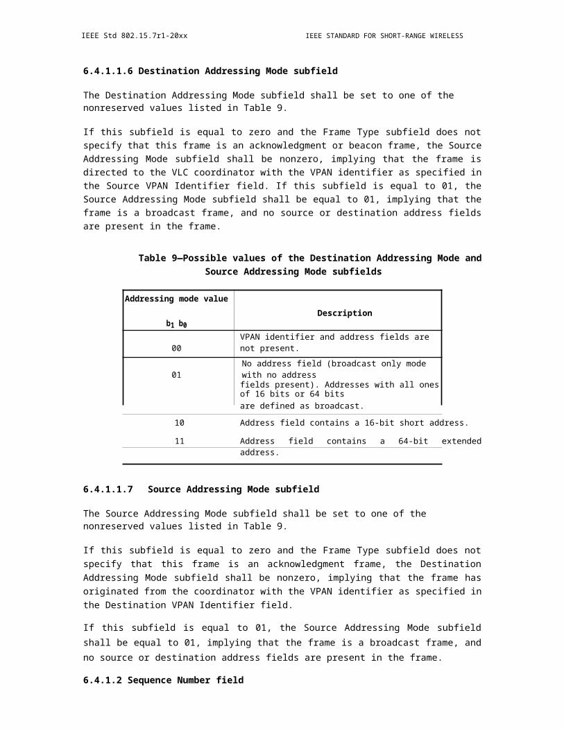
OPTICAL COMMUNICATION IEEE Std 802.15.7r1-20xx
The semantics of the MLME-AdditionalBeacon.indication primitive are as follows:
MLME-AdditionalBeacon.indication (
Reason
DeviceAddr
)
Table 10 16 specifies the parameters for the MLME-AdditionalBeacon.indication primitive.
Insert Table 10 16 MLME-AdditionalBeacon.indication primitive here
When generated
The MLME-AdditionalBeacon.indication primitive is generated by the MLME of a coordinator and issued to its next higher layer to indicate the reception of an additional beacon request command received by the PHY.
Effect on receipt
On receipt of the MLME-AdditionalBeacon.indication primitive, the next higher layer of the coordinator is notified of the additional beacon request command sent by an unassociated device. The next higher layer may then allocate a GTS for additional beacon transmission.
7.4.2.5 Neighbor report primitives
The MLME-SAP NeighborReport management primitives define how the coordinator triggers a neighboring VPAN report and how the requested devices to perform the report.
7.4.2.5.1 MLME-NeighborReport.request
The MLME-NeighborReport.request primitive allows the coordinator to generate and send a Neighboring VPAN report request command to devices.
The semantics of the MLME-NeighborReport.request primitive are as follows:
MLME-NeighborReport.request(
ReportDevicesList,
ReportType,
)
Insert Table 10 17 MLME-NeighborReport.request here
When generated
On receipt of the MLME -SYNC-LOSS.indication primitive with the LossReason parameter set to VPAN_ID_CONFLICT by the next higher layer of the coordinator, it shall issue a MLME-NeighborReport.request primitive to its MLME.
Copyright © 2011 IEEE. All rights reserved. 271
IEEE Std 802.15.7r1-20xx IEEE STANDARD FOR SHORT-RANGE WIRELESS
Effect on receipt
The MLME of the coordinator shall generate a neighboring VPAN report request command and send the command to the device specified by the ReportDeviceList. If multiple devices have been requested by the next higher layer, the MLME shall generate multiple neighboring VPAN report request command and send the command to the multiple devices respectively.
7.4.2.5.2 MLME- NeighborReport.indication
7.4.2.5.3 MLME-NeighborReport.confirm
The MLME-NeighborReport.confirm primitive provides the result of a requested neighboring VPAN report to the next higher layer of the coordinator.
The semantics of the MLME-NeighborReport.confirm primitive are as follows:
MLME-NeighborReport.confirm (
Result,
UnacknowledgedDevices,
NumberNeighboringVPAN Descriptor,
NeighboringVPAN Descriptor[0],
DetectDeviceList[0],
……
NeighboringVPAN Descriptor[N-1],
DetectDeviceList[N-1],
)
Insert Table 10 18 MLME-NeighborReport. confirm here
When generated
When the neighboring VPAN report indication commands from each requested device have been received by the MLME of the coordinator, or when the TBD time expires, the MLME of the coordinator shall issue the MLME-NeighborReport.confirm primitive to its next higher layer to report the result of the requested report.
Effect on receipt
The next higher layer of the coordinator shall be notified of the result of the requested neighboring VPAN report on receipt of the MLME-NeighborReport.confirm primitive.
272 Copyright © 20xx IEEE. All rights reserved.

OPTICAL COMMUNICATION IEEE Std 802.15.7r1-20xx
7.4.2.6 GTS management primitives
The MLME-SAP GTS management primitives define how GTSs are requested and maintained. A device or a coordinator expecting a contention-free transmission shall use these primitives to establish, modify, or terminate a flow.
7.4.2.6.1 MLME-FlowEstablishment.request (TBD)
7.4.2.6.2 MLME-FlowEstablishment.indication (TBD)
7.4.2.6.3 MLME-FlowEstablishment.response (TBD)
7.4.2.6.4 MLME-FlowEstablishment.confirm (TBD)
7.4.2.6.5 MLME-FlowModify.request (TBD)
7.4.2.6.6 MLME-FlowModify.indication (TBD)
7.4.2.6.7 MLME-FlowModify.response (TBD)
7.4.2.6.8 MLME-FlowModify.confirm (TBD)
7.4.2.6.9 MLME-FlowTerminate.request (TBD)
7.4.2.6.10 MLME-FlowTerminate.indication (TBD)
7.4.2.6.11 MLME-FlowTerminate.response (TBD)
7.4.2.6.12 MLME-FlowTerminate.confirm (TBD)
7.4.2.7 Primitives for updating the superframe configuration
The MLME-SAP start primitives define how a coordinator can initiate a new VPAN or to begin using a new superframe configuration.
7.4.2.7.1 MLME-START.request
The semantics of the MLME-START.request primitive are as follows:
MLME-START.request(
VPANId,
CoordShortAddr,
BPdescriptor,
CAP Descriptor,
CFPPresenceIndication,
CFP Descriptor,
SuperframeSequenceNumber,
Copyright © 2011 IEEE. All rights reserved. 273

IEEE Std 802.15.7r1-20xx IEEE STANDARD FOR SHORT-RANGE WIRELESS
CoordRealignment,
VPANMode,
Countdown
)
Table 10 19 specifies the parameters for the MLME-START.request primitive.
Insert Table 10 19 MLME-START.request here
When generated
The MLME-START.request primitive is generated by the next higher layer of a prospective coordinator when it has finished the scan procedure and needs to establish a new VPAN, or generated by the next higher layer of a coordinator when it needs to use a new superframe configuration for implementing the VPAN realignment.
Effect on receipt
On receipt of the MLME-START.request primitive, the MLME of the coordinator shall generate a beacon frame based on the provided arguments and broadcast the beacon frame if the CoordRealignment is set to FALSE, or the MLME of the coordinator shall generate a coordinator realignment command and broadcast it if the CoordRealignment is set to TRUE.
MLME-START.confirm
The MLME-START.confirm primitive reports the results of the attempt to start a new VPAN or to use a new superframe configuration.
The semantics of the MLME-START.confirm primitive are as follows:
MLME-START. confirm (
status
)
Table 10 20 specifies the parameters for the MLME-START. confirm primitive.
Insert Table 10 20 MLME-START. confirm here
When generated
The MLME-START.confirm primitive is generated by the MLME and issued to its next higher layer in response to an MLME-START.request primitive. The MLME shall generate the MLME-START.confirm primitive when it has finished sending the beacon frame if the CoordRealignment in the corresponding MLME-START.request primitive is set to FALSE, or the the MLME shall generate the MLME-START.confirm primitive when it has finished sending the coordinator realignment command frame if the CoordRealignment in the corresponding MLME-START.request primitive is set to TRUE.
Effect on receipt
274 Copyright © 20xx IEEE. All rights reserved.
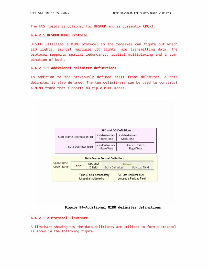
OPTICAL COMMUNICATION IEEE Std 802.15.7r1-20xx
On receipt of the MLME-START.confirm primitive, the next higher layer of the coordinator is notified of the result of the attempt to establish a new VPAN or to use a new superframe configuration.
7.4.2.8 Primitives for synchronization loss with a coordinator
MLME-SYNC-LOSS.indication
MLME-SYNC-LOSS.indication primitive indicates the loss of synchronization with a coordinator.
The semantics of the MLME-SYNC-LOSS.indication primitive are as follows:
MLME-SYNC-LOSS.indication(
LossReason,
VPANId
)
Table 10 21 defines the parameters for the MLME-SYNC-LOSS.indication primitive.
Insert Table 10 21 MLME-SYNC-LOSS.indication here
When generated
The MLME -SYNC-LOSS.indication primitive is generated by the MLME of a device and issued to its next higher layer in the event of a loss of synchronization with the coordinator. It is also generated by the MLME of the coordinator and issued to its next higher layer in the event of a VPAN ID conflict.
Effect on receipt
On receipt of the MLME-SYNC-LOSS.indication primitive, the next higher layer is notified of a loss of synchronization or a VPAN ID conflict.
7.4.2.9 primitive for a heterogeneous network
As described in 1.2, command frames (association request command, flow setup request, flow update request command, etc.) from type 2 devices to a coordinator shall be send trough RF link first and then relayed to the coordinators through a wired link (power line, Ethernet, cable, etc.) in a heterogeneous network, which is a different way than it is sent through the VLC link. Therefore, particular primitives are needed so as to send the command frame successfully through the RF link and wired link. MLME-SAP command primitives defines how a command frame shall be transmitted in a heterogeneous network when a type 2 device has a command frame that needs to be sent to the coordinator by the RF link and the backhaul link.
7.4.2.9.1 MLME-COMMAND.indication
The MLME-COMMAND.indication primitive allows the MLME of the device to provide a command frame to its next higher layer.
The semantics of the MLME-COMMAND.indication primitive are as follows:
MLME-COMMAND.indication (
Copyright © 2011 IEEE. All rights reserved. 275

IEEE Std 802.15.7r1-20xx IEEE STANDARD FOR SHORT-RANGE WIRELESS
DstAddr,
SrcAddr,
CommandFrame
)
Table 10 22 specifies the parameters for the MLME-COMMAND.indication primitive.
Insert Table 10 22 MLME-COMMAND.indication primitive here
When generated
When the MLME of the device generates a command frame that needs to be sent to the coordinator, it shall generate a MLME-COMMAND.indication primitive and issue the MLME-COMMAND.indication primitive to its next higher layer.
Effect on receipt
On receipt of the MLME- COMMAND.indication primitive, the next higher layer of the device may generate a next higher layer message based on the provided arguments and shall send the message to the the next higher layer of the coordinator through the RF link and backhaul link. The command frame generated by the MLME shall be embedded in the next higher layer message.
7.4.2.9.2 MLME-COMMAND.request
The MLME-COMMAND.request primitive allows the next higher layer of the coordinator to request its MLME to identify and process a command frame received through the RF link and backhaul link.
The semantics of the MLME-COMMAND.request primitive are as follows:
MLME-COMMAND.request (
DstAddr,
SrcAddr,
CommandFrame
)
Table 10 23 specifies the parameters for the MLME-COMMAND. request primitive.
Insert Table 10 23 MLME-COMMAND. request primitive here
When generated
The next higher layer of the coordinator shall generate a MLME-COMMAND.request primitive when it has received the next higher layer message and issue the MLME-COMMAND.request primitive to its MLME.
Effect on receipt
276 Copyright © 20xx IEEE. All rights reserved.
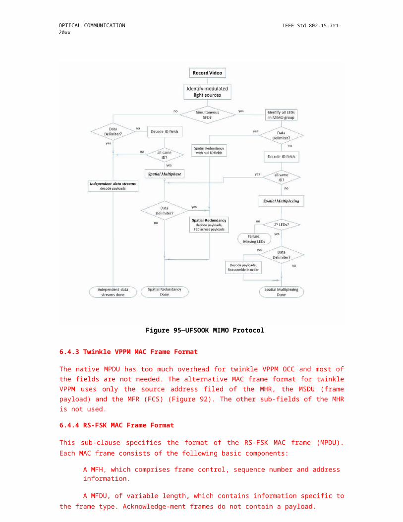
OPTICAL COMMUNICATION IEEE Std 802.15.7r1-20xx
On receipt of the MLME -COMMAND.request primitive, the MLME of the coordinator shall process the command frame provided in this primitive the same way as it was received through the VLC link.
7.4.2.10 primitives for writing MIB attributes
MLME-SAP set primitives define how MIB attributes may be written.
7.4.2.10.1 MLME-SET.request
The MLME-SET.request primitive attempts to write the given value to the indicated MIB attribute.
The semantics of the MLME-SET.request primitives are as follows:
MLME-SET.request(
MIBAttribute,
MIBAttributeIndex,
MIBAttributeValue
)
Table 10 24 specifies the parameters for the MLME-SET.request primitive.
Insert Table 10 24 MLME-SET.request primitive here
When generated
The MLME-SET.request primitive is generated by the next higher layer when it needs to set some MIB attributes and issued to its MLME to write the indicated MIB attribute.
Effect on receipt
On receipt of the MLME-SET.request primitive, the MLME shall attempt to write the given value to the indicated MIB attribute.
7.4.2.10.2 MLME-SET.confirm
The MLME-SET.confirm primitive reports the results of an attempt to write a value to a MIB attribute.
The semantics of the MLME-SET.confirm primitive are as follows:
MLME-SET.confirm(
Status,
MIBAttribute,
MIBAttributeIndex
)
Table 10 25 specifies the parameters for the MLME-SET.confirm primitive.
Copyright © 2011 IEEE. All rights reserved. 277

IEEE Std 802.15.7r1-20xx IEEE STANDARD FOR SHORT-RANGE WIRELESS
Insert Table 10 25 MLME-SET.confirm primitive here
When generated
The MLME-SET.confirm primitive is generated by the MLME and issued to its next higher layer when in response to an MLME -SET.request primitive. The MLME -SET.confirm primitive returns a status of either SUCCESS, indicating the requested value was written to the indicated MIB attribute, or the appropriate error code.
Effect on receipt
On receipt of the MLME -SET.confirm primitive, the next higher layer is notified of the result of its request to set the value of a MIB attribute.
7.4.2.11 Primitives for resetting the MAC sublayer
MLME-SAP reset primitives specify how to reset the MAC sublayer to its default values.
All devices shall provide an interface for these reset primitives.
7.4.2.11.1 MLME-RESET.request
See section 6.3.6.1 of 802.15.7-2011
7.4.2.11.2 MLME-RESET.confirm
See section 6.3.6.2 of 802.15.7-2011
7.5 MAC constants and PIB attributes
This subclause specifies the constants and attributes required by the MAC sublayer.
7.5.1 MAC constants
The constants that define the characteristics of the MAC sublayer are presented in Table 61.
Table 61—MAC sublayer constants
Constant Description Value
aBaseSlotDuration The number of optical clocks forming a superframe 60slot when the superframe order is equal to 0 (see6.2.1.1).
aBaseSuperframeDuration The number of optical clocks forming a superframe aBaseSlotDuration when the superframe order is equal to 0. aNumSuperframeSlots
aExtendedAddress The 64-bit (IEEE) address assigned to the device. Device specific
aGTSDescPersistenceTime The number of superframes in which a GTS descriptor 4exists in the beacon frame of the coordinator.
278 Copyright © 20xx IEEE. All rights reserved.

OPTICAL COMMUNICATION IEEE Std 802.15.7r1-20xx
Table 61—MAC sublayer constants (continued)
Constant Description Value
aMaxBeaconOverhead The maximum number of octets added by the MAC 75sublayer to the MSDU of a beacon frame.
aMaxBeaconPayloadLength The maximum size, in octets, of a beacon payload. aMaxPHYFrameSize –aMaxBeaconOverhead
aMaxLostBeacons The number of consecutive lost beacons that will 4cause the MAC sublayer of a receiving device todeclare a loss of synchronization.
aMaxMACSafePayloadSize The maximum number of octets that can be aMaxPHYFrameSize –transmitted in the MSDU field of an unsecured MAC aMaxMPDUUnsecureframe that will be guaranteed not to exceed dOverheadaMaxPHYFrameSize.
aMaxMACPayloadSize The maximum number of octets that can be aMaxPHYFrameSize –transmitted in the MSDU field. aMinMPDUOverhead
aMaxMPDUUnsecuredOverhead The maximum number of octets added by the MAC 25sublayer to the PSDU without security.
aMaxSIFSFrameSize The maximum size of an MPDU, in octets, that can be 18followed by a SIFS period.
aMinCAPLength The minimum number of optical clocks forming the 440CAP. This ensures that MAC commands can still betransferred to devices when GTSs are being used.An exception to this minimum shall be allowed for theaccommodation of the temporary increase in thebeacon frame length needed to perform GTSmaintenance (as defined in 6.4.6.1.3).
aMinMPDUOverhead The minimum number of octets added by the MAC 9sublayer to the PSDU.
aNumSuperframeSlots The number of slots contained in any superframe. 16
aUnitBackoffPeriod The number of optical clocks forming the basic time 20period used by the unslotted random access algorithm.
7.5.2 MAC PIB attributes
The MAC PIB comprises the attributes required to manage the MAC sublayer of a device. The attributes contained in the MAC PIB are presented in Table 62 and Table 69. Attributes marked with a dagger (†) are read-only attributes (i.e., attribute can only be set by the MAC sublayer), which can be read by the next higher layer using the MLME-GET.request primitive. All other attributes can be read or written by the next higher layer using the MLME-GET.request or MLME-SET.request primitives, respectively. Higher layers may impose additional constraints on read/write operations, without making devices non-compliant. Attributes marked with a diamond () are optional for a device (i.e., not operating as a coordinator).
The read- only attribute macAckWaitDuration is dependent on a combination of constants and PHY PIB attributes. The formula for relating the constants and attributes is shown in Equation (1).
AckWaitTime =backoff period + aTurnaroundTime-RX-TX + clock period numSymAckFrame (1)
where numSymAckFrame is the number of bits in the acknowledgment frame and is equal to 103 for PHY I and II and 111 for PHY III. For B-ACK mode, the AckWaitTime would be larger, depending on the number
Copyright © 2011 IEEE. All rights reserved. 279

IEEE Std 802.15.7r1-20xx IEEE STANDARD FOR SHORT-RANGE WIRELESS
of acknowledgments in the B-ACK mode as explained in 6.4.6.2. The clock period is obtained via the optical rates specified in Table 76, Table 77, and Table 78.
The attribute macMaxFrameTotalWaitTime may be set by the next higher layer and is dependent upon a combination of PHY and MAC PIB attributes and constants. The formula relating the attributes and constants is shown in Equation (2).
macMaxFrameTotalWaitTime = (2)
m – 1 + 2macMaxBE – 1 macMaxCSMABackoffs – m aUnitBackoffPeriod + phyMaxFrameDuration 2macMinBE + k
k = 0
where
m is min(macMaxBE-macMinBE, macMaxCSMABackoffs)
Table 62—MAC PIB attributes
Attribute Identifier Type Range Description Default
macAckWaitDuration†0x40 Integer Refer to The maximum number of Dependent
Equation (1) optical clocks to wait for an onacknowledgment frame to currentlyarrive following a transmitted selecteddata frame. PHY.
This value is dependent onthe supported PHY, whichdetermines both the selectedlogical channel. Thecalculated value is the time tocommence transmitting theACK plus the length of theACK frame. Thecommencement time isdescribed in 6.2.7.4.2.
macAgeingTime TBD Integer 0-255 The ageing time of local neighboring VPANs descriptor list
20
macAssociatedVPAN- 0x41 Boolean TRUE or Indication of whether the FALSECoord FALSE device is associated to the
VPAN through thecoordinator. A value ofTRUE indicates the devicehas associated through thecoordinator. Otherwise, thevalue is set to FALSE.
macAssociation- 0x42 Boolean TRUE or Indication of whether a FALSEPermit FALSE coordinator is currently
allowing association. A valueof TRUE indicates thatassociation is permitted.
280 Copyright © 20xx IEEE. All rights reserved.
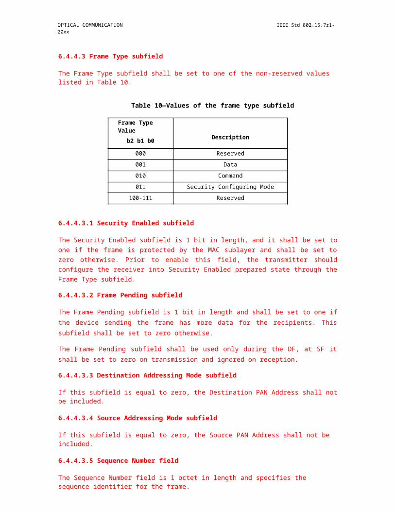
OPTICAL COMMUNICATION IEEE Std 802.15.7r1-20xx
Table 62—MAC PIB attributes (continued)
Attribute Identifier Type Range Description Default
macAutoRequest 0x43 Boolean TRUE or Indication of whether a TRUEFALSE device automatically sends a
data request command if itsaddress is listed in the beaconframe. A value of TRUEindicates that the data requestcommand is automaticallysent.
This attribute also affects thegeneration of the MLME-BEACON-NOTIFY.indication primitive(see 7.3.3.1.1).
macBeaconPayload 0x44 Set of — The contents of the beaconNULLoctets payload.
macBeaconPayload- 0x45 Integer 0 – aMax- The length, in octets, of the0Length Beacon- beacon payload.
PayloadLengthmacBeaconOrder 0x46 Integer 0–15 Specification of how often the
coordinator transmits itsbeacon. If BO = 15, thecoordinator will not transmit
15a periodic beacon. Refer to6.2.1.1 for an explanation ofthe relationship between thebeacon order and the beaconinterval.
macBeaconTxTime† 0x47 Integer 0x000000– The time that the device0xffffff transmitted its last beacon
frame, in symbol periods. Themeasurement shall be taken atthe same symbol boundarywithin every transmittedbeacon frame, the location ofwhich is implementation 0x000000specific.
This is a 24-bit value, and theprecision of this value shallbe a minimum of 20 bits, withthe lowest four bits being theleast significant.
macBSN 0x48 Integer 0x00–0xff The sequence number added Randomto the transmitted beacon value fromframe. within the
rangemacCoordinationPeriod TBD Integer 1-256 The number of superframes
that consists of a coordination period.
10
macCoordExtended- 0x49 IEEE An extended The 64-bit address of theAddress address 64-bit IEEE coordinator through which —
address the device is associated.
Copyright © 2011 IEEE. All rights reserved. 281
IEEE Std 802.15.7r1-20xx IEEE STANDARD FOR SHORT-RANGE WIRELESS
Table 62—MAC PIB attributes (continued)
Attribute Identifier Type Range Description Default
macCoordShort-Address 0x4a Integer 0x0000–0xffff The 16-bit short addressassigned to the coordinatorthrough which the device isassociated. A value of
0xffff0xfffe indicates that thecoordinator is only using its64-bit extended address. Avalue of 0xffff indicates thatthis value is unknown.
macDSN 0x4b Integer 0x00–0xff The sequence number added Randomto the transmitted data or value fromMAC command frame. within the
rangemacGTSPermit 0x4c Boolean TRUE or TRUE if the coordinator is to
FALSE accept GTS requests. FALSE TRUEotherwise.
macLastDetect TBD Integer 0-255 The time that a neighboring VPAN has not been detected since last detection. Used for update the local neighboring VPAN descriptor list
20
macMaxBE 0x4d Integer 3–15 The maximum value of the 5backoff exponent, BE, in theunslotted random accessalgorithm. Refer to 6.2.1.8 fora detailed explanation of thebackoff exponent.
macMaxCSMABackoffs 0x4e Integer 0–5 The maximum number ofbackoffs the unslottedrandom access algorithm will 4attempt before declaring achannel access failure.
macMaxFrameTotal- 0x4f Integer Refer to The maximum number ofWaitTime Equation (2) optical clocks in a beacon-
enabled VPAN, or in anonbeacon-enabled VPAN, towait either for a frameintended as a response to adata request frame or for abroadcast frame following a
Dependentbeacon with the frame onpending subfield set to one. currently
This attribute, which shallselectedPHY
only be set by the next higherlayer, is dependent uponmacMinBE, macMaxBE,macMaxCSMABackoffs andthe number of optical clocksper octet. Refer to 7.5.2 forthe formula relating theattributes.
macMaxFrameRetries 0x50 Integer 0–7 The maximum number of 3retries allowed after atransmission failure.
macMaxRABackoffs TBD Integer 0-15 The maximal backoff times for random access.
4
282 Copyright © 20xx IEEE. All rights reserved.
OPTICAL COMMUNICATION IEEE Std 802.15.7r1-20xx
Table 62—MAC PIB attributes (continued)
Attribute Identifier Type Range Description Default
macMinBE 0x51 Integer 0–macMaxBE The minimum value of thebackoff exponent (BE) in theunslotted random access
3algorithm. Refer to 6.2.1.8 fora detailed explanation of thebackoff exponent.
macMinLIFSPeriod† 0x52 Integer As defined in The minimum number of DependentTable 88 in optical clocks forming a LIFS on
9.3.4 period. currentlyselectedPHY.
macMinSIFSPeriod† 0x53 Integer As defined in The minimum number of DependentTable 88 in optical clocks forming a SIFS on
9.3.4 period. currentlyselectedPHY.
macVPANId 0x54 Integer 0x0000–0xffff The 16-bit identifier of theVPAN on which the device isoperating. If this value is 0xffff0xffff, the device is notassociated.
macResponseWaitTime 0x55 Integer 2–64 The maximum time, in 32multiples ofaBaseSuperframeDuration, adevice shall wait for aresponse command frame tobe available following arequest command frame.
macRxOnWhenIdle 0x56 Boolean TRUE or Indication of whether theFALSE MAC sublayer is to enable its
receiver during idle periods.For a beacon-enabled VPAN,this attribute is relevant only
FALSEduring the CAP of theincoming superframe. For anonbeacon-enabled VPAN,this attribute is relevant at alltimes.
macSecurityEnabled 0x57 Boolean TRUE or Indication of whether theFALSE MAC sublayer has security
enabled.
A value of TRUE indicates TRUEthat security is enabled, whilea value of FALSE indicatesthat security is disabled.
Copyright © 2011 IEEE. All rights reserved. 283

IEEE Std 802.15.7r1-20xx IEEE STANDARD FOR SHORT-RANGE WIRELESS
Table 62—MAC PIB attributes (continued)
Attribute Identifier Type Range Description Default
macShortAddress 0x58 Integer 0x0000–0xffff The 16-bit address that thedevice uses to communicatein the VPAN. If the device isthe coordinator, this valueshall be chosen before aVPAN is started. Otherwise,the address is allocated by acoordinator during
0xffffassociation.
A value of 0xfffe indicatesthat the device has associatedbut has not been allocated anaddress. A value of 0xffffindicates that the device doesnot have a short address.
macSuperframe-Order† 0x59 Integer 0–15 The length of the active 15portion of the outgoingsuperframe, including thebeacon frame. If superframeorder, SO, = 15, thesuperframe will not be activefollowing the beacon. Referto 6.2.1.1 for an explanationof the relationship betweenthe superframe order and thesuperframe duration.
macTimestamp- 0x5a Boolean TRUE or Indication of whether the Imple-Supported† FALSE MAC sublayer supports the mentation
optional time stamping specificfeature for incoming andoutgoing data frames.
macTransaction- 0x5b Integer 0x0000–0xffff The maximum time (in unit 0x01f4PersistenceTime periods) that a transaction is
stored by a coordinator andindicated in its beacon.
The unit period is governedby macBeaconOrder, BO, asfollows: For 0 BO 14, theunit period will be aBase-SuperframeDuration * 2BO.For BO = 15, the unit periodwill be aBaseSuperframe-Duration.
macDim 0x5c Integer 0–1000 Percentage dimming; 0 is 0% 0visibility and 1000 is 100%visibility.
macNumAcks 0x5d Integer 0–15 Maximum number of times 3not receiving ACKs to triggerfast link recovery procedure.
284 Copyright © 20xx IEEE. All rights reserved.
OPTICAL COMMUNICATION IEEE Std 802.15.7r1-20xx
Table 62—MAC PIB attributes (continued)
Attribute Identifier Type Range Description Default
macLinkTimeOut 0x5e Integer 0–255 A timer initiated when the 63link recovery procedure istriggered. If the timer expireswhile the device has notreceived any fast linkrecovery response (FLR RSP)signal since the fast linkrecovery procedure istriggered, the device assumesthat the link is broken andcannot be recovered. Therange for macLinkTimeOut isdefined in terms of thenumber of superframes.
macDimOverrideRequest 0x5f Boolean TRUE or shall be set to ‘1’ after VLC 0FALSE device association and shall
be set to ‘0’ after the VLCdevice disassociation
macDimPWMOverrideRe 0x60 Boolean TRUE or shall be set to ‘1’ to inform 0quest FALSE the dimmer circuit that the
VLC device will beresponsible for dimming andto disable any PWM circuitpresent in the dimmer
macDimDataFailureIndic 0x61 Boolean TRUE or shall be set to ‘1’ when the 0ation FALSE device is unable to perform
data communication underdimming
macDuringASSOCColor 0x62 Unsigned 0–255 Use macDuringASSOCColor 0for the color assignment ofthe CVD frame when thecolor function for theassociation MAC stateindication between MLME-ASSOCIATE.request andMLME-ASSOCIATE.confirm is usedby the CVD frame.The unsigned integer is theindex for the look-up table forthe color function table,phyColorFunction, as shownin Table 125, PHY PIBattributes.
Copyright © 2011 IEEE. All rights reserved. 285

IEEE Std 802.15.7r1-20xx IEEE STANDARD FOR SHORT-RANGE WIRELESS
Table 62—MAC PIB attributes (continued)
Attribute Identifier Type Range Description Default
macDuringDISASSOCCo 0x63 Unsigned 0–255 Use 0lor macDuringDISASSOCColor
for the color assignment ofthe CVD frame when thecolor function for thedisassociation MAC stateindication between MLME-DISASSOCIATE.request andMLME-DISASSOCIATE.confirm isused by the CVD frame.The unsigned integer is theindex for the look-up table forthe color function table,phyColorFunction, as shownin Table 125, PHY PIBattributes.
macDuringSCANColor 0x64 Unsigned 0–255 Use macDuringSCANColor 0for the color assignment ofthe CVD frame when thecolor function for the scanMAC state indicationbetween MLME-SCAN.request and MLME-SCAN.confirm is used by theCVD frame.The unsigned integer is theindex for the look-up table forthe color function table,phyColorFunction, as shownin Table 125, PHY PIBattributes.
macColorReceived 0x65 Unsigned 0–255 Use macColorReceived for 0the color assignment oft heCVD Frame when the ACKframe is sent and the colorfunction for the ACK stateindication is used by the CVDframe.
The unsigned integer is theindex for the look-up table forthe color function table,phyColorFunction, as shownin Table 125, PHY PIBattributes.
286 Copyright © 20xx IEEE. All rights reserved.
OPTICAL COMMUNICATION IEEE Std 802.15.7r1-20xx
Table 62—MAC PIB attributes (continued)
Attribute Identifier Type Range Description Default
macColorNotReceived 0x66 Unsigned 0–255 Use macColorNotReceived 0for the color assignment ofthe CVD Frame when theACK frame is not sent but thecolor function for the non-ACK state indication is usedby the CVD frame.
The unsigned integer is theindex for the look-up table forthe color function table,phyColorFunction, as shownin Table 125, PHY PIBattributes.
macCQIColorLFER 0x67 Unsigned 0–255 Use macCQIColorLFER for 0the color assignment of theCVD frame when the colorfunction for the channelquality indication showingthe low FER is used by theCVD frame.The unsigned integer is theindex for the look-up table forthe color function table,phyColorFunction, as shownin Table 125, PHY PIBattributes.
macCQIColorMFER 0x68 Unsigned 0–255 Use macCQIColorMFER for 0the color assignment of theCVD frame when the colorfunction for the channelquality indication showingthe medium FER is used bythe CVD frame.The unsigned integer is theindex for the look-up table forthe color function table,phyColorFunction, as shownin Table 125, PHY PIBattributes.
macCQIColorHFER 0x69 Unsigned 0–255 Use macCQIColorHFER for 0the color assignment of theCVD frame when the colorfunction for the channelquality indication showingthe high FER is used by theCVD frame.The unsigned integer is theindex for the look-up table forthe color function table,phyColorFunction, as shownin Table 125, PHY PIBattributes.
Copyright © 2011 IEEE. All rights reserved. 287

IEEE Std 802.15.7r1-20xx IEEE STANDARD FOR SHORT-RANGE WIRELESS
Table 62—MAC PIB attributes (continued)
Attribute Identifier Type Range Description Default
macCFAppColor 0x6a Unsigned 0–255 Use macCFAppColor for the 0color assignment of the CVDframe when the color functionfor the indication ofapplication-dependentinformation is used by theCVD frame.The unsigned integer is theindex for the look-up table forthe color function table,phyColorFunction, as shownin Table 125, PHY PIBattributes.
macColorStabilization 0x6b Binary 00–11 The color stabilization action 0Integer entailed when receiving CVD
frames. The information forsetting these two bits is foundin Table 22.
macColorStabilizationTi 0x6c Integer 0x0–0xffffffff Minimum time between two 0x004000mer stabilization measurements 00
(see 9.5.4) that are send backto the corresponding CSK Tx.The time is measured inmultiples ofaMaxPHYFrameSize framesfor color stabilization.
macUseDimmedOOKmod 0x6d Boolean TRUE or Shall be set to 1 when 0e FALSE dimming is to be performed
in the dimmed OOK mode inconjunction with OOK.
macTimeStampOffset 0x6e Octet 0x00–0xff The location of the time 0stamp after the end of thepreamble in optical clocks.
macUseBlinkingNotificati 0x6f Boolean TRUE or Shall be set to 0 when 1on FALSE blinking notification is to be
performed.
macBlinkingNotificationF 0x70 Integer 0–10 The frequency of blinking 0requency notification
0: 0.25Hz1: 0.5Hz2: 0.75Hz3: 1Hz4: 1.25Hz5: 1.5Hz6: 1.75Hz7: 2Hz8: 2.25Hz9: 2.5Hz10: 2.75Hz
macLedIdAmbiguityResol 0x71 Unsigned 0-255 This attribute resolves the 0ution ambiguity of a short LED ID
by appending it to a SSID asshown in table TBD.
288 Copyright © 20xx IEEE. All rights reserved.
OPTICAL COMMUNICATION IEEE Std 802.15.7r1-20xx
Table 62—MAC PIB attributes (continued)
Attribute Identifier Type Range Description Default
mac_symbol_rate 5-20 To adapt TX symbol rate 10versus RX frame ratevariation when RX has theminimum frame rate belowthe symbol rate.
mac_bandwidth 2 kHz - 8 kHz To adapt the number of TXLEDs spatially (resolution)versus RX image resolutionmode.
mac_LEDs_spatial_resol int To adapt the number of TX 2ution LEDs spatially (resolution)
versus RX image resolutionmode.
mac_DS_rate int 60 - 120 To control the length of a data 100subframe. Shorter data framecan support for longerdistance transmission.
macTxMode 0x91 Unsigned 0-255 This attribute indicates the 0MAC transmission mode isvisible or Invisible.0 : Visible VTASC Mode1 : Invisible Mode - BlendingMethod2 : Invisible Mode -Watermarking Method
macTxCamerEnable 0x92 Unsigned 0-255 This attribute indicates the 0Transmitter is Enabled withCamera or not for InteractiveReceiver distance specificdata transfer control.0 : Camera not connected1 : Camera connected
macRxDistance 0x93 Unsigned 0-255 This attribute notify the 0Receiver distance fromTransmitter
macTxDataType 0x94 Unsigned 0-255 This attribute indicates the 0type of data to be transmitted.0 : Normal Data (MediaContent, Information Contentbased on the Application usedfor)1 : ID Data2 : Authentication Data
maxDataLength 0x95 Integer 0-65535 This attribute specify the 0length of the data to betransmitted
Copyright © 2011 IEEE. All rights reserved. 289

IEEE Std 802.15.7r1-20xx IEEE STANDARD FOR SHORT-RANGE WIRELESS
Table 63—Ambiguity Resolution Method
PIB Attribute Value Method Name Method
0 ID without payload Preappend ID to SSID
1 ID and SSID hash Preappend ID to hash resolved SSID
2 w/ or w/o ID and IP address Preappend ID to provided IP address
7.6 Optical-clock-rate selection
The standard supports multiple optical clock rates in order to accommodate a wide variety of optical sources and receivers. The standard also supports the use of asymmetric clock rates between transmitter and receiver since they constitute independent chains and may support different clock-rate ranges. The multiple clocks associated with each PHY type are respectively shown in Table 76, Table 77, and Table 78.
Support for the minimum clock rate for a given PHY type shall be mandatory for all TX and RX devices. All specified clock rates less than the maximum supported clock rate in a given device shall also be supported in that device. If a clock rate is supported, all data rates associated with that clock rate shall be supported. The preamble, headers, and payload in the PHY shall have the same clock rate. The header shall be sent at lowest data rate for the chosen clock rate. The payload can choose any data rate belonging to the chosen clock rate.
The clock-rate negotiation can be supported with or without explicit clock-rate negotiation, as indicated in the capabilities information field in Table 18. Explicit clock-rate negotiation implies that the devices shall transmit a clock rate change notification command as in 6.7.14 before a new clock rate is used. If explicit clock-rate negotiation is not used, the device shall have the capability to perform synchronization at all supported optical clock rates without any prior knowledge of the clock rate chosen at the transmitter for communication.
7.6.1 Optical-clock-rate selection for P2P topology
Let us assume that Device 1 supports clock rates at the transmitter (C1, C2, … C t1), where Ct1 is the maximum clock rate supported at the transmitter at of the coordinator. Also, C1 < C2 < ... < Ct1. Within a PHY type, the clock rates are integral multiples of each other to make the clock generation and selection simple at the transmitter (i.e., Ci+1/Ci = m, which is an integer). The receiver may support more or less clock rates than the transmitter since the receiver optronics is physically independent of the transmitter clock. Let the clocks supported by the receiver of device 1 be C1, C2, … Cr 1, where Cr1 is the maximum clock rate supported at the receiver of device 1. Similarly, let Ct2 and Cr 2 be the maximum clock rates supported by the device 2. Support for the lowest clock rate C1 is mandatory at both the transmitter and receiver for all devices i.e., t1 , t2, r1, r 2 1. For every clock rate, there is an associated set of data rates at the physical layer. This data rate is dependent on the modulation, RLL coding, and FEC used at the physical layer for a given clock rate. Let the data rate be represented by rate{Ci,p }, where C i is the chosen clock rate and 1 p N(Ci), where N(Ci) is the number of physical-layer data rates associated with clock rate Ci.
7.6.1.1 Explicit notification
In Figure 157, a device sends the association request at the lowest clock C1 at a physical layer data rate
rate{C1,k}. The data rate index k is typically chosen to be the lowest data rate to guarantee maximum range and reliability for the given clock rate. In this association request, the device also informs the coordinator of
290 Copyright © 20xx IEEE. All rights reserved.

OPTICAL COMMUNICATION IEEE Std 802.15.7r1-20xx
the maximum clock rate supported by its transmitter and receiver (Ct2, Cr2). The maximum-clock-rate information is provided by the capabilities IE as shown in Table 18, which shall also be transmitted during this association request. The coordinator receives the association request and compares the received information about the supported clocks at the device and compares it with its supported clocks. In order for it to communicate, it shall select a clock rate C_SEL1 that is equal to or lower than MAX _C_SEL1, which is the minimum of its maximum transmitter clock and the maximum receiver clock supported by the coordinator. The decision to use clock rates lower than MAX_ C_SEL1 and MAX_C_SEL 2 at the coordinator and the device for, respectively, the transmission depends on the performance and throughput needs of the coordinator and the devices. The coordinator also sends an association grant back to the device at the same lowest clock rate C1 supported by all devices. The devices then exchange the selected clock frequencies by using the clock-rate-change notification command for future communication before they switch to the selected clock frequencies. The devices may also decide to change the clock rate anytime in future communication, as long as it is below MAX_C_SEL1 and MAX_C_SEL2 for transmission at the coordinator and device, respectively.
clock-rate selection for P2P topology
coordinator (supports clocks TX: C1,C2,...Ct1 RX: C1,C2,...Cr1)
device (supports clocks TX: C1,C 2,...Ct2 RX: C1,C2,...Cr2)
association request (clock C1, rate{C1,k}) inform max
clock of device (Ct2,Cr2)
association grant (clock C1, rate{C1,j})
inform max clock of coordinator(Ct1,Cr1)
MAX_C_SEL1 = min (Cr2, Ct1) MAX_C_SEL2 = min (Cr1, Ct2)
C_SEL1 ≤ MAX_C_SEL1 C_SEL2 ≤ MAX_C_SEL2
inform selected clock C_SEL1 (clock C1)inform selected clock C_SEL2 (clock C1)
device to coordinator (clock C_SEL2)
coordinator to device (clock C_SEL1)
There is a data rate table rate{Ci,j} associated with each clock rate Ci
where j is the data rate index associated with clock rate Ci
Figure 157—Clock-rate selection for P2P topology (explicit notification)
7.6.1.2 Without explicit notification
It is also possible for the coordinator to send the association grant at the new clock rate C_SEL2 and not have to explicitly exchange notification information, as shown in Figure 158, if the coordinator has the capability to detect all clock rates less than its maximum receive clock rate. In this case, communication can occur without overhead for explicit notification.
Copyright © 2011 IEEE. All rights reserved. 291
IEEE Std 802.15.7r1-20xx IEEE STANDARD FOR SHORT-RANGE WIRELESS
coordinator (supports clocks TX: C1,C 2,...Ct1 RX: C1,C2,...Cr1)
MAX_C_SEL1 = min (Cr2, Ct1)
C_SEL1 ≤ MAX_C_SEL1
clock-rate selection for P2P topology
association request (clock C1, rate{C1,k}) inform
max clock of device (Ct2,Cr2)
device (supports clocks TX: C1,C
2,...Ct2 RX: C1,C2,...Cr2)
association grant(clock C_SEL1, rate{C_SEL2,j})inform max clock of coordinator (Ct1,Cr1)
MAX_C_SEL2 = min (Cr1, Ct2) C_SEL2 ≤ MAX_C_SEL2
device to coordinator(clock C_SEL2)
coordinator to device(clock C_SEL1)
There is a data rate table rate{Ci,j} associated with each clock rate Ci
where j is the data rate index associated with clock rate Ci
Figure 158—Clock-rate selection for P2P topology (without explicit notification)
7.6.2 Optical-clock-rate selection for star
topology 7.6.2.1 Explicit notification
Figure 159 shows the optical clock-rate selection for a star topology. In this case, let us assume device 1 to be a coordinator. The coordinator will send a broadcast message via a beacon to all nodes, such as devices 2 and 3, and inform them of its supported clock rates. The CAP always uses the lowest clock rate C1 for uplink contention. The coordinator and the devices communicate the selected clock frequencies during the CFP using clock rate C1 before switching to the selected clock frequencies. The information about the coordinator capabilities is broadcast using the capabilities IE. The current clock in use, and any change of clock, is communicated via the clock rate change notification.
292 Copyright © 20xx IEEE. All rights reserved.
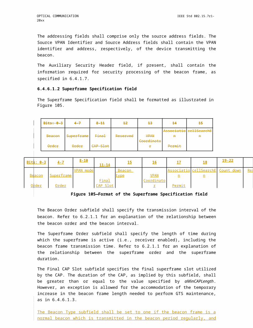
OPTICAL COMMUNICATION IEEE Std 802.15.7r1-20xx
clock-rate selection for star topology
coordinator device 2 device 3(supports clocks (supports clocks (supports clocksTX: C1,C2,...Ct1 TX: C1,C2,...Ct2 TX: C1,C2,...Ct3
RX: C1,C2,...Cr1) RX: C1,C2,...Cr2) RX: C1,C2,...Cr3)
beacon (clock C1,rate{C1,k})
inform max clock of coordinator (Ct1,Cr1)
contention access period (clock C1,rate{C1,j} )
inform max clock of device 2 (Ct2,Cr2)
contentionaccess period (clock C1,rate{C1,m})
inform max clock of device 3 (Ct3,Cr3)
C_SEL12 ≤ min (Cr2, Ct1) C_SEL2 ≤ min (Cr1, Ct2) C_SEL3 ≤ min (Cr1, Ct3)C_SEL13 ≤ min (Cr3, Ct1)
CFP: inform clock C_SEL12 (clock C1)CFP: inform clock C_SEL13 (clock C1)
CFP: inform clock C_SEL2 (clock C1)CFP: inform clock C_SEL3 (clock C1)
CFP: device 2 to coordinator (clock C_SEL2)CFP: coordinator to device 2 (clock C_SEL12)
CFP: device 3 to coordinator (clock C_SEL3)CFP: coordinator to device 3 (clock C_SEL13)
Figure 159—Clock-rate selection for star topology (explicit notification)
7.6.2.2 Without explicit notification
Similar to the P2P topology, the clock-rate selection for the star topology can also occur without explicit notification, as shown in Figure 160.
Copyright © 2011 IEEE. All rights reserved. 293
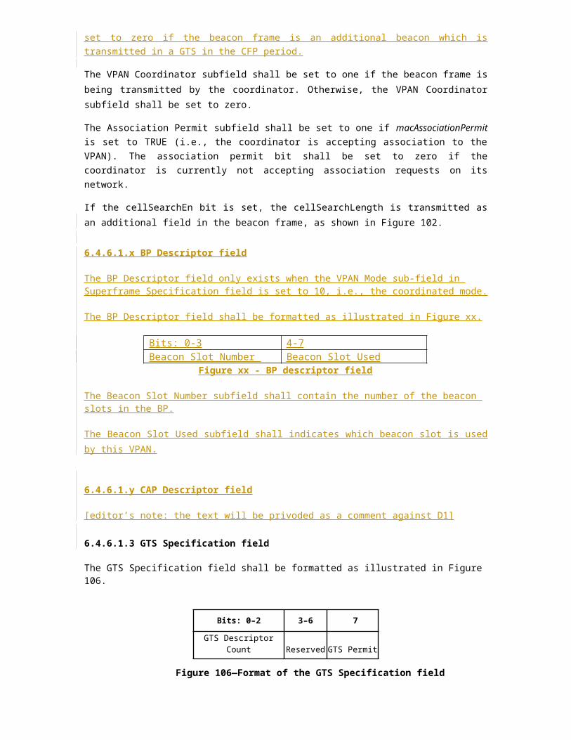
IEEE Std 802.15.7r1-20xx IEEE STANDARD FOR SHORT-RANGE WIRELESS
clock-rate selection for star topology
coordinator device 2 device 3(supports clocks (supports clocks (supports clocksTX: C1,C2,...Ct1 TX: C1,C2,...Ct2 TX: C1,C2,...Ct3
RX: C1,C2,...Cr1) RX: C1,C2,...Cr2) RX: C1,C2,...Cr3)
beacon (clock C1,rate{C1,k})inform max clock of coordinator (Ct1,Cr1)
C_SEL2 ≤ min (Cr1, Ct2) C_SEL3 ≤ min (Cr1, Ct3)
contention access period (clock C1,rate{C1,j})
inform max clock of device 2 (Ct2,Cr2)
contention access period(clock C1,rate{C1,m})
inform max clock of device 3 (Ct3,Cr3)
C_SEL12 ≤ min (Cr2, Ct1)C_SEL13 ≤ min (Cr3, Ct1)
CFP: device 2 to coordinator (clock C_SEL2)
CFP: coordinator to device 2 (clock C_SEL12)
CFP: device 3 to coordinator (clock C_SEL3)
CFP: coordinator to device3 (clock C_SEL13)
Figure 160—Clock-rate selection for star topology (without explicit notification)
7.6.3 Clock-rate selection for multicast topology
7.6.3.1 Explicit notification
Figure 161 and Figure 162 show the clock-rate selection for multicast topologies assuming bi-directional communication.
294 Copyright © 20xx IEEE. All rights reserved.

OPTICAL COMMUNICATION IEEE Std 802.15.7r1-20xx
clock-rate selection for multicast topology
coordinator device 2 device 3(supports clocks (supports clocks (supports clocksTX: C1,C2,...Ct1 TX: C1,C2,...Ct2 TX: C1,C2,...Ct3
RX: C1,C2,...Cr1) RX: C1,C2,...Cr2) RX: C1,C2,...Cr3)
beacon (clock C1, rate{C1,j})inform max clock of coordinator (Ct1,Cr1)
C_SEL2 ≤ min (Cr1, Ct2) C_SEL3 ≤ min (Cr1, Ct3)
contention access period(clock C 1, rate{C1,j})
inform max clock of device 2 (Ct2,Cr2)
contention access period(clock C 1, rate{C1,m})
inform max clock of device 3 (Ct3,Cr3)
C_SEL1 ≤ min (Cr2, Cr3, Ct1)C_SEL12 ≤ min (Cr2, Ct1)C_SEL13 ≤ min (Cr3, Ct1)
CFP: inform clock change to C_SEL1 (clock C_SEL12)
CFP: inform clock change to C_SEL1 (clock C_SEL13)
multicast message (clock C_SEL1)
Figure 161—Clock-rate selection for multicast (assuming bi-directional communication)
Copyright © 2011 IEEE. All rights reserved. 295

IEEE Std 802.15.7r1-20xx IEEE STANDARD FOR SHORT-RANGE WIRELESS
7.6.3.2 Without explicit notification
clock-rate selection for multicast topology
coordinator device 2 device 3(supports clocks (supports clocks (supports clocksTX: C1,C2,...Ct1 TX: C1,C2,...Ct2 TX: C1,C2,...Ct3RX: C1,C2,...Cr1) RX: C1,C2,...Cr2) RX: C1,C2,...Cr3)
beacon (clock C1, rate{C1,j})inform max clock of coordinator (Ct1,Cr1)
C_SEL2 ≤ min (Cr1, Ct2) C_SEL3 ≤ min (Cr1, Ct3)
contention access period(clock C 1, rate{C1,j})
inform max clock of device 2 (Ct2,Cr2)
contention access period(clock C1, rate{C1,m})
inform max clock of device 3 (Ct3,Cr3)
C_SEL1 ≤ min (Cr2, Cr3, Ct1)
multicast message (clock C_SEL1)
Figure 162—Clock-rate selection for multicast (bi-directional communication and no explicit notification)
7.7 Message sequence charts illustrating MAC-PHY interaction
This subclause illustrates the main tasks specified in this standard. Each task is described by use of a message sequence chart to illustrate the chronological order, rather than the exact timing, of the primitives required for each task.
The primitives necessary for the coordinator to start a new VPAN are shown in Figure 163. The first action the next higher layer takes after resetting the MAC sublayer is to initiate a scan to search for other VPANs in the area. An active scan is required. The steps for performing an active scan are shown in Figure 167.
Once a new VPAN is established, the coordinator is ready to accept requests from other devices to join the VPAN. Figure 164 shows the primitives issued by a device requesting association, while Figure 165 illustrates the steps taken by a coordinator allowing association. In the process of joining a VPAN, the device requesting association will perform either a passive or an active scan to determine which VPANs in the area are allowing association; Figure 166 and Figure 167 detail the primitives necessary to complete a passive scan and an active scan, respectively.
The primitives necessary for transmitting and receiving a single data frame are shown next. The actions taken by the originator of the frame are shown in Figure 168, while the actions taken by the recipient are shown in Figure 169.
296 Copyright © 20xx IEEE. All rights reserved.
OPTICAL COMMUNICATION IEEE Std 802.15.7r1-20xx
.
Figure 163—VPAN start message sequence chart—coordinator
Copyright © 2011 IEEE. All rights reserved. 297
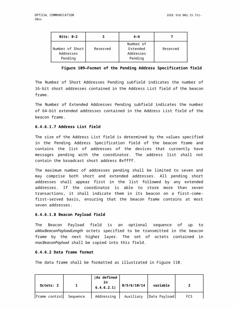
IEEE Std 802.15.7r1-20xx IEEE STANDARD FOR SHORT-RANGE WIRELESS
Figure 164—Association message sequence chart—device
298 Copyright © 20xx IEEE. All rights reserved.

OPTICAL COMMUNICATION IEEE Std 802.15.7r1-20xx
Figure 165—Association message sequence chart—coordinator
Copyright © 2011 IEEE. All rights reserved. 299
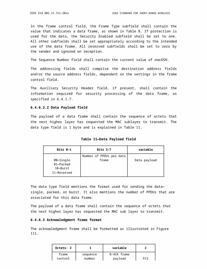
IEEE Std 802.15.7r1-20xx IEEE STANDARD FOR SHORT-RANGE WIRELESS
Figure 166—Passive scan message sequence chart
300 Copyright © 20xx IEEE. All rights reserved.
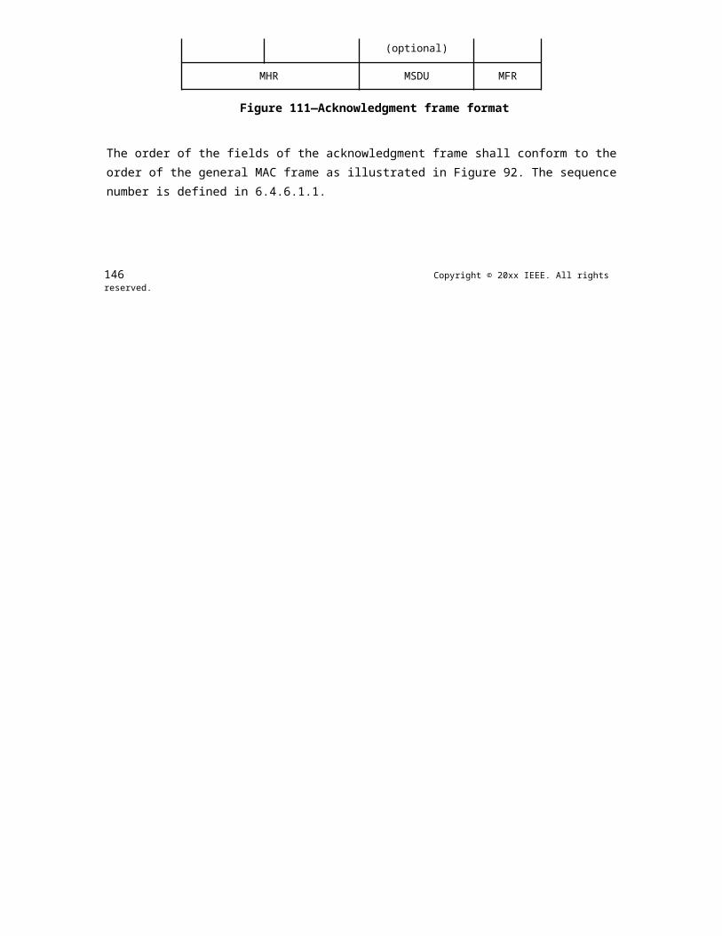
OPTICAL COMMUNICATION IEEE Std 802.15.7r1-20xx
Figure 167—Active scan message sequence chart
Copyright © 2011 IEEE. All rights reserved. 301
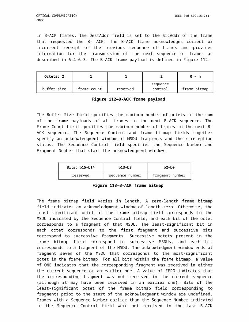
IEEE Std 802.15.7r1-20xx IEEE STANDARD FOR SHORT-RANGE WIRELESS
Figure 168—Data-transmission message sequence chart—originator
302 Copyright © 20xx IEEE. All rights reserved.
OPTICAL COMMUNICATION IEEE Std 802.15.7r1-20xx
Figure 169—Data-transmission message sequence chart—recipient
8. Security suite specifications
8.1 Overview
The MAC sublayer is responsible for providing security services on specified incoming and outgoing frames when requested to do so by the higher layers. This standard supports the following security services (as defined in 4.7 for definitions):
— Data confidentiality
Copyright © 2011 IEEE. All rights reserved. 303
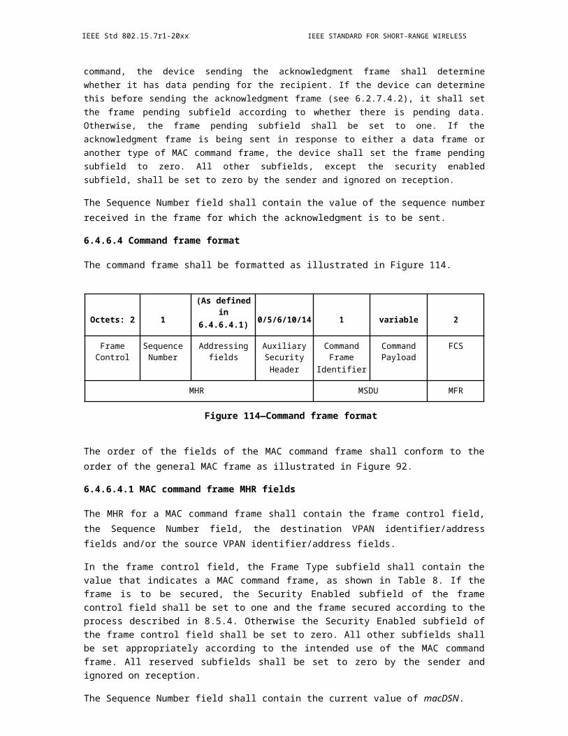
IEEE Std 802.15.7r1-20xx IEEE STANDARD FOR SHORT-RANGE WIRELESS
— Data authenticity— Replay protection
The information determining how to provide the security is found in the security-related PIB (as defined in Table 69 in 8.5.1).
8.2 Functional description
A device may optionally implement security. A device that does not implement security shall not provide a mechanism for the MAC sublayer to perform any cryptographic transformation on incoming and outgoing frames nor require any PIB attributes associated with security. A device that implements security shall provide a mechanism for the MAC sublayer to provide cryptographic transformations on incoming and outgoing frames using information in the PIB attributes associated with security when the macSecurityEnabled attribute is set to TRUE.
If the MAC sublayer is required to transmit a frame or receives an incoming frame, the MAC sublayer shall process the frame as specified in 8.2.1 and 8.2.3, respectively.
8.2.1 Outgoing frame security procedure
The inputs to this procedure are the frame to be secured and the SecurityLevel, KeyIdMode, KeySource, and KeyIndex parameters from the originating primitive or automatic request PIB attributes. The outputs from this procedure are the status of the procedure and, if this status is SUCCESS, the secured frame. If outgoing frame security procedure is not successful, the frame is discarded
The outgoing frame security procedure involves the following steps as applicable:
a) If the Security Enabled subfield of the frame control field of the frame to be secured is set to zero, the procedure shall set the security level to zero.
b) If the Security Enabled subfield of the frame control field of the frame to be secured is set to one, the procedure shall set the security level to the SecurityLevel parameter. If the resulting security level is zero, the procedure shall return with a status of UNSUPPORTED_SECURITY.
c) If the macSecurityEnabled attribute is set to FALSE and the security level is not equal to zero, the procedure shall return with a status of UNSUPPORTED_SECURITY.
d) The procedure shall determine whether the frame to be secured satisfies the constraint on the maximum length of MAC frames, as follows:1) The procedure shall set the length M, in octets, of the Authentication field to zero if the
security level is equal to zero and shall determine this value from the security level and Table 67 otherwise.
2) The procedure shall determine the length AuxLen, in octets, of the auxiliary security header (see 8.4) using KeyIdMode and the security level.
3) The procedure shall determine the data expansion as AuxLen + M.4) The procedure shall check whether the length of the frame to be secured, including data
expansion and FCS, is less than or equal to aMaxPHYFrameSize. If this check fails, the procedure shall return with a status of FRAME_TOO_LONG.
e) If the security level is zero, the procedure shall set the secured frame to be the frame to be secured and return with the secured frame and a status of SUCCESS.
f) The procedure shall set the frame counter to the macFrameCounter attribute. If the frame counter has the value 0xffffffff, the procedure shall return with a status of COUNTER_ERROR and all keys associated with the device shall be reinitialized and updated as discussed in 8.5.5.
g) The procedure shall obtain the key using the outgoing frame key retrieval procedure as described in 8.2.2. If that procedure fails, the procedure shall return with a status of UNAVAILABLE_KEY.
h) The procedure shall insert the auxiliary security header into the frame, with fields set as follows:
304 Copyright © 20xx IEEE. All rights reserved.

OPTICAL COMMUNICATION IEEE Std 802.15.7r1-20xx
1) The Security Level subfield of the Security Control field shall be set to the security level.2) The Key Identifier Mode subfield of the Security Control field shall be set to the KeyIdMode
parameter.3) The Frame Counter field shall be set to the frame counter.4) If the KeyIdMode parameter is set to a value not equal to zero, the Key Source and Key Index
subfields of the Key Identifier field shall be set to the KeySource and KeyIndex parameters, respectively.
i) The procedure shall then use aExtendedAddress, the frame counter, the security level, and the key to produce the secured frame according to the transformation process known as CCM* [or the extension of CCM, which is the combined counter with CBC-MAC (i.e., cipher block chaining message authentication code) mode of operation] that is described in the security operations (see 8.3.4).1) If the SecurityLevel parameter specifies the use of encryption (as defined in Table 67 in
8.4.2.1), the encryption operation shall be applied only to the actual payload field within the MSDU, i.e., the Beacon Payload field (see 6.4.6.1.8), Command Payload field (see 6.4.6.4.3), or Data Payload field (see 6.4.6.2.2), depending on the frame type. The corresponding payload field is passed to the CCM* transformation process described in 8.3.4 as the unsecured payload (as defined in Table 64 in 8.3.4.2). The resulting encrypted payload shall substitute the original payload.
2) The remaining fields in the MSDU part of the frame shall be passed to the CCM* transformation process described in 8.3.4 as the nonpayload fields (see Table 64).
3) The ordering and exact manner of performing the encryption and integrity operations and the placement of the resulting encrypted data or integrity code within the MSDU field shall be as defined in 8.3.4.
j) The procedure shall increment the frame counter by one and set the macFrameCounter attribute to the resulting value.
k) The procedure shall return with the secured frame and a status of SUCCESS.
8.2.2 Outgoing frame key retrieval procedure
The inputs to this procedure are the frame to be secured and the KeyIdMode, KeySource, and KeyIndex parameters from the originating primitive. The outputs from this procedure are a passed or failed status and, if passed, a key.
The outgoing frame key retrieval procedure involves the following steps as applicable:
a) If the KeyIdMode parameter is set to 0x00 (implicit key identification), the procedure shall determine the key lookup data and key lookup size as follows:1) If the Destination Addressing Mode subfield of the frame control field of the frame is set to
0x00 and the macVPANCoordShortAddress attribute is set to a value in the range 0x0000– 0xfffd (i.e., the short address is used), the key lookup data shall be set to the 2-octet Source VPAN Identifier field of the frame right-concatenated (see B.2.1. of IEEE Std 802.15.4-2006) with the 2-octet macVPANCoordShortAddress attribute right-concatenated with the single octet 0x00. The key lookup size shall be set to five.
2) If the Destination Addressing Mode subfield of the frame control field of the frame is set to 0x00 and the macVPANCoordShortAddress attribute is set to 0xfffe (i.e., the extended address is used), the key lookup data shall be set to the 8-octet macVPANCoordExtendedAddress attribute right-concatenated (see B.2.1 of IEEE Std 802.15.4-2006) with the single octet 0x00. The key lookup size shall be set to nine.
3) If the Destination Addressing Mode subfield of the frame control field of the frame is set to 0x02, the key lookup data shall be set to the 2-octet Destination VPAN Identifier field of the frame right-concatenated (see B.2.1 of IEEE Std 802.15.4-2006) with the 2-octet Destination Address field of the frame right-concatenated with the single octet 0x00. The key lookup size shall be set to five.
Copyright © 2011 IEEE. All rights reserved. 305
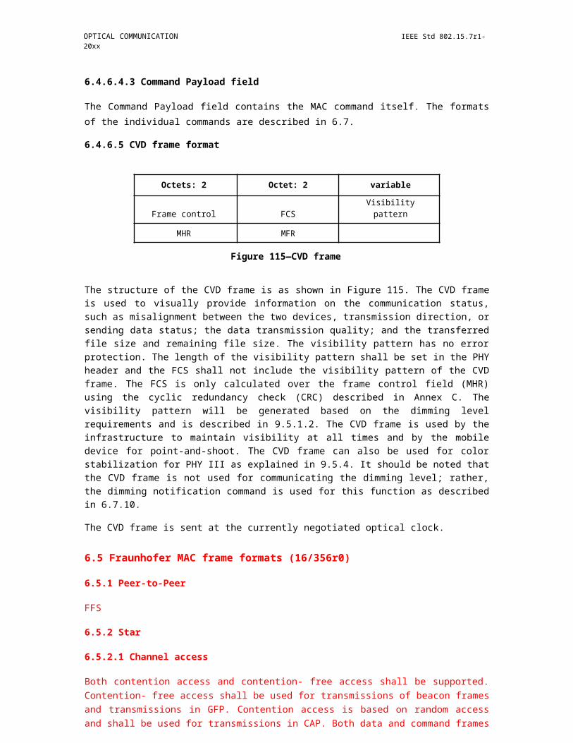
IEEE Std 802.15.7r1-20xx IEEE STANDARD FOR SHORT-RANGE WIRELESS
4) If the Destination Addressing Mode subfield of the frame control field of the frame is set to 0x03, the key lookup data shall be set to the 8-octet Destination Address field of the frame right-concatenated (see B.2.1 of IEEE Std 802.15.4-2006) with the single octet 0x00. The key lookup size shall be set to nine.
b) If the KeyIdMode parameter is set to a value not equal to 0x00 (explicit key identification), the procedure shall determine the key lookup data and key lookup size as follows:1) If the KeyIdMode parameter is set to 0x01, the key lookup data shall be set to the 8-octet
macDefaultKeySource attribute right-concatenated (see B.2.1 of IEEE Std 802.15.4-2006) with the single octet KeyIndex parameter. The key lookup size shall be set to nine.
2) If the KeyIdMode parameter is set to 0x02, the key lookup data shall be set to the 4-octet KeySource parameter right-concatenated (see B.2.1 of IEEE Std 802.15.4-2006) with the single octet KeyIndex parameter. The key lookup size shall be set to five.
3) If the KeyIdMode parameter is set to 0x03, the key lookup data shall be set to the 8-octet KeySource parameter right-concatenated (see B.2.1 of IEEE Std 802.15.4-2006) with the single octet KeyIndex parameter. The key lookup size shall be set to nine.
c) The procedure shall obtain the KeyDescriptor by passing the key lookup data and the key lookup size to the KeyDescriptor lookup procedure as described in 8.2.5. If that procedure returns with a failed status, this procedure shall also return with a failed status.
d) The MAC sublayer shall set the key to the Key element of the KeyDescriptor.e) The procedure shall return with a passed status, having obtained the key identifier and the key.
NOTE—For broadcast frames, the outgoing frame key retrieval procedure will result in a failed status if implicit key identification is used. Hence, explicit key identification should be used for broadcast frames.
8.2.3 Incoming frame security procedure
The input to this procedure is the frame to be unsecured. The outputs from this procedure are the unsecured frame, the security level, the key identifier mode, the key source, the key index, and the status of the procedure. All outputs of this procedure are assumed to be invalid unless and until explicitly set in this procedure. It is assumed that the PIB attributes associating KeyDescriptors in macKeyTable with a single, unique device or a number of devices will have been established by the next higher layer. The incoming frame security procedure involves the following steps:
a) If the Security Enabled field of the frame control field of the frame to be unsecured is set to zero, the procedure shall set the security level to zero.
b) If the Security Enabled field of the Frame Control field of the frame to be unsecured is set to one, the procedure shall set the unsecured frame to be the frame to be unsecured and return with a status ofUNSUPPORTED_LEGACY.
c) If the Security Enabled field of the Frame Control field of the frame to be unsecured is set to one, the procedure shall set the security level and the key identifier mode to the corresponding fields of the Security Control field of the auxiliary security header of the frame to be unsecured, and the key source and key index to the corresponding fields of the Key Identifier field of the auxiliary security header of the frame to be unsecured, if present. If the resulting security level is zero, the procedure shall set the unsecured frame to be the frame to be unsecured and return with a status ofUNSUPPORTED_SECURITY.
d) If the macSecurityEnabled attribute is set to FALSE, the procedure shall set the unsecured frame to be the frame to be unsecured and return with a status of SUCCESS if the security level is equal to zero and with a status of UNSUPPORTED_SECURITY otherwise.
e) The procedure shall determine whether the frame to be unsecured meets the minimum security level by passing the security level, the frame type, and, depending on whether the frame is a MAC command frame, the first octet of the MSDU (i.e., command frame identifier for a MAC command frame) to the incoming security level checking procedure as described in 8.2.8. If that procedure
306 Copyright © 20xx IEEE. All rights reserved.
OPTICAL COMMUNICATION IEEE Std 802.15.7r1-20xx
fails, the procedure shall set the unsecured frame to be the frame to be unsecured and return with a status of IMPROPER_SECURITY_LEVEL.
f) If the security level is set to zero, the procedure shall set the unsecured frame to be the frame to be unsecured and return with a status of SUCCESS.
g) The procedure shall obtain the KeyDescriptor, DeviceDescriptor, and KeyDeviceDescriptor using the incoming frame security material retrieval procedure described in 8.2.4. If that procedure fails, the procedure shall set the unsecured frame to be the frame to be unsecured and return with a status of UNAVAILABLE_KEY.
h) The procedure shall determine whether the frame to be unsecured conforms to the key usage policy by passing the KeyDescriptor, the frame type, and, depending on whether the frame is a MAC command frame, the first octet of the MSDU (i.e., command frame identifier for a MAC command frame) to the incoming key usage policy checking procedure as described in 8.2.9. If that procedure fails, the procedure shall set the unsecured frame to be the frame to be unsecured and return with a status of IMPROPER_KEY_TYPE.
i) If the Exempt element of the DeviceDescriptor is set to FALSE and if the incoming security level checking procedure of step e) above had as output the “conditionally passed” status, the procedure shall set the unsecured frame to be the frame to be unsecured and return with a status ofIMPROPER_SECURITY_LEVEL.
j) The procedure shall set the frame counter to the Frame Counter field of the auxiliary security header of the frame to be unsecured. If the frame counter has the value 0xffffffff, the procedure shall set the unsecured frame to be the frame to be unsecured and return with a status of COUNTER_ERROR.
k) The procedure shall determine whether the frame counter is greater than or equal to the FrameCounter element of the DeviceDescriptor. If this check fails, the procedure shall set the unsecured frame to be the frame to be unsecured and return with a status of COUNTER_ERROR.
l) The procedure shall then use the ExtAddress element of the DeviceDescriptor, the frame counter, the security level, and the Key element of the KeyDescriptor to produce the unsecured frame according to the CCM* inverse transformation process described in the security operations (see 8.3.5).1) If the security level specifies the use of encryption (as defined in Table 67 in 8.4.2.1), the
decryption operation shall be applied only to the actual payload field within the MSDU, i.e., the Beacon Payload field (see 6.4.6.1.8), Command Payload field (see 6.4.6.4.3), or Data Payload field (see 6.4.6.2.2), depending on the frame type. The corresponding payload field shall be passed to the CCM* inverse transformation process described in 8.3.5 as the secure payload.
2) The remaining fields in the MSDU part of the frame shall be passed to the CCM* inverse transformation process described in 8.3.5 as the nonpayload fields.
m) If the CCM* inverse transformation process fails, the procedure shall set the unsecured frame to be the frame to be unsecured and return with a status of SECURITY_ERROR.
n) The procedure shall increment the frame counter by one and set the FrameCounter element of the DeviceDescriptor to the resulting value.
o) If the FrameCounter element is equal to 0xffffffff, the procedure shall set the Blacklisted element of the KeyDeviceDescriptor.
p) The procedure shall return with the unsecured frame and a status of SUCCESS.
8.2.4 Incoming frame security material retrieval procedure
The input to this procedure is the frame to be unsecured. The outputs from this procedure are a passed or failed status and, if passed, a KeyDescriptor, a DeviceDescriptor, and a KeyDeviceDescriptor.
The incoming frame security material retrieval procedure involves the following steps as applicable:
a) If the Key Identifier Mode subfield of the Security Control field of the auxiliary security header of the frame is set to 0x00 (implicit key identification), the procedure shall determine the key lookup data and the key lookup size as follows:1) If the source address mode of the frame control field of the frame is set to 0x00 and the
macVPANCoordShortAddress attribute is set to a value in the range 0x0000–0xfffd (i.e., the
Copyright © 2011 IEEE. All rights reserved. 307
IEEE Std 802.15.7r1-20xx IEEE STANDARD FOR SHORT-RANGE WIRELESS
short address is used), the key lookup data shall be set to the 2-octet Destination VPAN Identifier field of the frame right-concatenated (see B.2.1 of IEEE Std 802.15.4-2006) with the 2-octet macVPANCoordShortAddress attribute right-concatenated with the single octet 0x00. The key lookup size shall be set to five.
2) If the source address mode of the frame control field of the frame is set to 0x00 and the macVPANCoordShortAddress attribute is set to 0xfffe (i.e., the extended address is used), the key lookup data shall be set to the 8-octet macVPANCoordExtendedAddress attribute right-concatenated (see B.2.1 of IEEE Std 802.15.4-2006) with the single octet 0x00. The key lookup size shall be set to nine.
3) If the source address mode of the frame control field of the frame is set to 0x02, the key lookup data shall be set to the 2-octet Source VPAN Identifier field of the frame, or to the 2-octet Destination VPAN Identifier field of the frame if the VPAN ID Compression subfield of the frame control field of the frame is set to one, right-concatenated (see B.2.1 of IEEE Std 802.15.4-2006) with the 2-octet Source Address field of the frame right-concatenated with the single octet 0x00. The key lookup size shall be set to five.
4) If the source address mode of the frame control field of the frame is set to 0x03, the key lookup data shall be set to the 8-octet Source Address field of the frame right-concatenated (see B.2.1 of IEEE Std 802.15.4-2006) with the single octet 0x00. The key lookup size shall be set to nine.
b) If the Key Identifier Mode subfield of the Security Control field of the auxiliary security header of the frame is set to a value not equal to 0x00 (explicit key identification), the procedure shall determine the key lookup data and key lookup size as follows:1) If the key identifier mode is set to 0x01, the key lookup data shall be set to the 8-octet
macDefaultKeySource attribute right-concatenated (see B.2.1 of IEEE Std 802.15.4-2006) with the 1-octet Key Index subfield of the Key Identifier field of the auxiliary security header. The key lookup size shall be set to nine.
2) If the key identifier mode is set to 0x02, the key lookup data shall be set to the right-concatenation (see B.2.1 of IEEE Std 802.15.4-2006) of the 4-octet Key Source subfield and the 1-octet Key Index subfield of the Key Identifier field of the auxiliary security header. The key lookup size shall be set to five.
3) If the key identifier mode is set to 0x03, the key lookup data shall be set to the right-concatenation (see B.2.1 of IEEE Std 802.15.4-2006) of the 8-octet Key Source subfield and the 1-octet Key Index subfield of the Key Identifier field of the auxiliary security header. The key lookup size shall be set to nine.
c) The procedure shall obtain the KeyDescriptor by passing the key lookup data and the key lookup size to the KeyDescriptor lookup procedure as described in 8.2.5. If that procedure returns with a failed status, the procedure shall also return with a failed status.
d) The procedure shall determine the device lookup data and the device lookup size as follows:1) If the source address mode of the frame control field of the frame is set to 0x00 and the
macVPANCoordShortAddress attribute is set to a value in the range 0x0000–0xfffd (i.e., the short address is used), the device lookup data shall be set to the 2-octet Destination VPAN Identifier field of the frame right-concatenated (see B.2.1 of IEEE Std 802.15.4-2006) with the 2-octet macVPANCoordShortAddress attribute. The device lookup size shall be set to four.
2) If the source address mode of the frame control field of the frame is set to 0x00 and the macVPANCoordShortAddress attribute is set to 0xfffe (i.e., the extended address is used), the device lookup data shall be set to the 8-octet macVPANCoordExtendedAddress attribute. The device lookup size shall be set to eight.
3) If the source address mode of the frame control field of the frame is set to 0x02, the device lookup data shall be set to the 2-octet Source VPAN Identifier field of the frame, or to the 2-octet Destination VPAN Identifier field of the frame if the VPAN ID Compression subfield of the frame control field of the frame is set to one, right-concatenated (see B.2.1 of IEEE Std 802.15.4-2006) with the 2-octet Source Address field of the frame. The device lookup size shall be set to four.
308 Copyright © 20xx IEEE. All rights reserved.
OPTICAL COMMUNICATION IEEE Std 802.15.7r1-20xx
4) If the source address mode of the frame control field of the frame is set to 0x03, the device lookup data shall be set to the 8-octet Source Address field of the frame. The device lookup size shall be set to eight.
e) The procedure shall obtain the DeviceDescriptor and the KeyDeviceDescriptor by passing the KeyDescriptor, the device lookup data, and the device lookup size to the blacklist checking procedure as described in 8.2.6. If that procedure returns with a failed status, the procedure shall also return with a failed status.
f) The procedure shall return with a passed status having obtained the KeyDescriptor, the DeviceDescriptor, and the KeyDeviceDescriptor.
8.2.5 Key descriptor lookup procedure
The inputs to this procedure are the key lookup data and the key lookup size. The outputs from this procedure are a passed or failed status and, if passed, a KeyDescriptor.
The KeyDescriptor lookup procedure involves the following steps as applicable:
a) For each KeyDescriptor in the macKeyTable attribute and for each KeyIdLookupDescriptor in the KeyIdLookupList of the KeyDescriptor, the procedure shall check whether the LookupDataSize element of the KeyIdLookupDescriptor indicates the same integer value, shown in Table 75, as the key lookup size and whether the LookupData element of the KeyIdLookupDescriptor is equal to the key lookup data. If both checks pass (i.e., there is a match), the procedure shall return with this (matching) KeyDescriptor and a passed status.
b) The procedure shall return with a failed status.
8.2.6 Blacklist checking procedure
The inputs to this procedure are the KeyDescriptor, the device lookup data, and the device lookup size. The outputs from this procedure are a passed or failed status and, if passed, a DeviceDescriptor and a KeyDeviceDescriptor.
The blacklist checking procedure involves the following steps as applicable:
a) For each KeyDeviceDescriptor in the KeyDeviceList of the KeyDescriptor:1) The procedure shall obtain the DeviceDescriptor using the DeviceDescriptorHandle element
of the KeyDeviceDescriptor.2) If the UniqueDevice element of the KeyDeviceDescriptor is set to TRUE, the procedure shall
return with the DeviceDescriptor, the KeyDeviceDescriptor, and a passed status if the BlackListed element of the KeyDeviceDescriptor is set to FALSE, or the procedure shall return with a failed status if this Blacklisted element is set to TRUE.
3) If the UniqueDevice element of the KeyDeviceDescriptor is set to FALSE, the procedure shall execute the DeviceDescriptor lookup procedure as described in 8.2.7, with the device lookup data and the device lookup size as inputs. If the corresponding output of that procedure is a passed status, the procedure shall return with the DeviceDescriptor, the KeyDevice-Descriptor, and a passed status if the Blacklisted element of the KeyDeviceDescriptor is set to FALSE, or the procedure shall return with a failed status if this Blacklisted element is set to TRUE.
b) The procedure shall return with a failed status.
8.2.7 Device descriptor lookup procedure
The inputs to this procedure are the DeviceDescriptor, the device lookup data, and the device lookup size. The output from this procedure is a passed or failed status.
Copyright © 2011 IEEE. All rights reserved. 309
IEEE Std 802.15.7r1-20xx IEEE STANDARD FOR SHORT-RANGE WIRELESS
The DeviceDescriptor lookup procedure involves the following steps as applicable:
a) If the device lookup size is four and the device lookup data is equal to the VPAN ID element of the DeviceDescriptor right-concatenated (see B.2.1 of IEEE Std 802.15.4-2006) with the ShortAddress element of the Device-Descriptor, this procedure shall return with a passed status.
b) If the device lookup size is eight and the device lookup data is equal to the ExtAddress element of the DeviceDescriptor, this procedure shall return with a passed status.
c) The procedure shall return with a failed status.
8.2.8 Incoming security level checking procedure
The inputs to this procedure are the incoming security level, the frame type and the command frame identifier. The output from this procedure is a passed, failed, or “conditionally passed” status.
The incoming security level checking procedure involves the following steps as applicable:
a) It is recommended to use MIC for all secure messages as defined in Table 67. For each SecurityLevelDescriptor in the macSecurityLevelTable attribute:1) If the frame type is not equal to 0x03 and the frame type is equal to the FrameType element of
the SecurityLevelDescriptor, the procedure shall compare the incoming security level (as SEC1) with the SecurityMinimum element of the SecurityLevelDescriptor (as SEC2) according to the algorithm described in 8.4.2.1. If this comparison fails (i.e., evaluates to FALSE), the procedure shall return with a “conditionally passed” status if the DeviceOverrideSecurityMinimum element of the SecurityLevelDescriptor is set to TRUE and the security level is set to zero and with a failed status otherwise.
2) If the frame type is equal to 0x03, the frame type is equal to the FrameType element of the SecurityLevelDescriptor, and the command frame identifier is equal to the CommandFrame-Identifier element of the SecurityLevelDescriptor, the procedure shall compare the incoming security level (as SEC1) with the SecurityMinimum element of the SecurityLevelDescriptor (as SEC2) according to the algorithm described in 8.4.2.1. If this comparison fails (i.e., evaluates to FALSE), the procedure shall return with a “conditionally passed” status if the DeviceOverrideSecurityMinimum element of the SecurityLevelDescriptor is set to TRUE and the security level is set to zero and with a failed status otherwise.
b) The procedure shall return with a passed status.
8.2.9 Incoming key usage policy checking procedure
The inputs to this procedure are the KeyDescriptor, the frame type, and the command frame identifier. The output from this procedure is a passed or failed status.
The incoming key usage policy checking procedure involves the following steps as applicable:
a) For each KeyUsageDescriptor in the KeyUsageList of the KeyDescriptor:1) If the frame type is not equal to 0x03 and the frame type is equal to the FrameType element of
the KeyUsageDescriptor, the procedure shall return with a passed status.2) If the frame type is equal to 0x03, the frame type is equal to the FrameType element of the
KeyUsageDescriptor, and the command frame identifier is equal to the CommandFrame-Identifier element of the KeyUsageDescriptor, the procedure shall return with a passed status.
b) The procedure shall return with a failed status.
310 Copyright © 20xx IEEE. All rights reserved.
OPTICAL COMMUNICATION IEEE Std 802.15.7r1-20xx
8.3 Security operations
This subclause describes the parameters for the CCM* security operations, as specified in Annex A of IEEE Std 802.15.4-2006.
8.3.1 Integer and octet representation
The integer and octet representation conventions specified in Annex A of IEEE Std 802.15.4-2006 are used throughout 8.3.
8.3.2 CCM* nonce
The CCM* nonce is a 13- octet string and is used for the advanced encryption standard (AES)-CCM* mode of operation (see B.2.2 of IEEE Std 802.15.4-2006). The nonce shall be formatted as shown in Figure 170, with the left most field in the figure defining the first (and left most) octets and the right most field defining the last (and right most) octet of the nonce.
Octets: 8 4 1
Source address Frame counter Security level
Figure 170—CCM* nonce
The source address shall be set to the extended address aExtendedAddress of the device originating the frame, the frame counter to the value of the respective field in the auxiliary security header (see 8.4), and the security level to the security level identifier corresponding to the Security Level subfield of the Security Control field of the auxiliary security header as defined in Table 67.
The source address, frame counter, and security level shall be represented as specified in 8.3.1.
8.3.3 CCM* prerequisites
Securing a frame involves the use of the CCM* mode encryption and authentication transformation, as described in B.4.1. of IEEE Std 802.15.4-2006. Unsecuring a frame involves the use of the CCM* decryption and authentication checking process, as described in B.4.2 of IEEE Std 802.15.4-2006. The prerequisites for the CCM* forward and inverse transformations are as follows:
— The underlying block cipher shall be the AES encryption algorithm as specified in B.3.1 of IEEE Std 802.15.4-2006.
— The bit ordering shall be as defined in 8.3.1.— The length in octets of the Length field L shall be 2 octets.— The length of the Authentication field M shall be 0 octets, 4 octets, 8 octets, or 16 octets, as required.
The length of the Authentication field M for the CCM* forward transformation and the CCM* inverse transformation is determined from Table 67, using the Security Level subfield of the Security Control field of the auxiliary security header of the frame.
8.3.4 CCM* transformation data representation
This subclause describes how the inputs and output of the CCM* forward transformation, as described in B.4.1 of IEEE Std 802.15.4-2006, are formed.
Copyright © 2011 IEEE. All rights reserved. 311
IEEE Std 802.15.7r1-20xx IEEE STANDARD FOR SHORT-RANGE WIRELESS
The inputs are as follows:
— Key— Nonce— a data— m data
The output is c data.
8.3.4.1 Key and nonce data inputs
The Key data for the CCM* forward transformation is passed by the outgoing frame security procedure described in 8.2.1. The nonce data for the CCM* transformation is constructed as described in 8.3.2.
8.3.4.2 a data and m data
In the CCM* transformation process, the data fields shall be applied as in Table 64.
Table 64—a data and m data for all security levels
Security level identifier a data m data
0x00 None None
0x01 MHR || Auxiliary security header || Nonpayload fields || NoneUnsecured payload fields
0x02 MHR || Auxiliary security header || Nonpayload fields || NoneUnsecured payload fields
0x03 MHR || Auxiliary security header || Nonpayload fields || NoneUnsecured payload fields
0x04 None Unsecured payload fields
0x05 MHR || Auxiliary security header || Nonpayload fields Unsecured payload fields
0x06 MHR || Auxiliary security header || Nonpayload fields Unsecured payload fields
0x07 MHR || Auxiliary security header || Nonpayload fields Unsecured payload fields
8.3.4.3 c data output
In the CCM* transformation process, the data fields that are applied, or right-concatenated and applied, represent octet strings.
The secured payload fields right-concatenated with the authentication tag shall substitute the unsecured payload field in the original unsecured frame to form the secured frame (see Table 65).
312 Copyright © 20xx IEEE. All rights reserved.
OPTICAL COMMUNICATION IEEE Std 802.15.7r1-20xx
Table 65—c data for all security levels
Security level identifier c data
0x00 None
0x01 MIC-32
0x02 MIC-64
0x03 MIC-128
0x04 Secured payload fields
0x05 Secured payload fields || MIC-32
0x06 Secured payload fields || MIC-64
0x07 Secured payload fields || MIC-128
8.3.5 CCM* inverse transformation data representation
This subclause describes how the inputs and output of the CCM* inverse transformation, as described in C.4.2 of IEEE Std 802.15.4-2006, are formed.
The inputs are as follows:
— Key— Nonce— c data— a data
The output is m data.
8.3.5.1 Key and nonce data inputs
The key data for the CCM* inverse transformation is passed by the incoming frame security procedure described in 8.2.3. The nonce data for the CCM* transformation is constructed as described in 8.3.2.
8.3.5.2 c data and a data
In the CCM* inverse transformation process, the data fields shall be applied as in Table 66.
8.3.5.3 m data output
The m data shall then substitute secured payload fields and authentication tag in the original secured frame to form the unsecured frame.
8.4 Auxiliary Security header
The Auxiliary Security Header field has a variable length and contains information required for security processing, including a Security Control field, a Frame Counter field, and a Key Identifier field. The Auxiliary Security Header field shall be present only if the Security Enabled subfield of the frame control field is set to one. The Auxiliary Security Header field shall be formatted as illustrated in Figure 171.
Copyright © 2011 IEEE. All rights reserved. 313
IEEE Std 802.15.7r1-20xx IEEE STANDARD FOR SHORT-RANGE WIRELESS
Table 66—c data and a data for all security levels
Security level identifier c data a data
0x00 None None
0x01 MIC-32 MHR || Auxiliary security header|| Nonpayload fields ||Securedpayload fields
0x02 MIC-64 MHR || Auxiliary security header|| Nonpayload fields || Securedpayload fields
0x03 MIC-128 MHR || Auxiliary security header|| Nonpayload fields || Securedpayload fields
0x04 Secured payload fields MHR || Auxiliary security header|| Nonpayload fields
0x05 Secured payload fields || MHR || Auxiliary security headerMIC-32 || Nonpayload fields
0x06 Secured payload fields || MHR || Auxiliary security headerMIC-64 || Nonpayload fields
0x07 Secured payload fields || MHR || Auxiliary security headerMIC-128 || Nonpayload fields
Octets: 1 4 0/1/5/9
Security Control Frame Counter Key Identifier
Figure 171—Format of the auxiliary security header
8.4.1 Integer and octet representation
The auxiliary security header is a MAC frame field (see 6.4.1.7) and, therefore, uses the representation conventions specified in 6.4.
8.4.2 Security Control field
The Security Control field is 1 octet in length and is used to provide information about what protection is applied to the frame. The Security Control field shall be formatted as shown in Figure 172.
Bit: 0–2 3–4 5–7
Security Level Key Identifier Mode Reserved
Figure 172—Security Control field format
314 Copyright © 20xx IEEE. All rights reserved.
OPTICAL COMMUNICATION IEEE Std 802.15.7r1-20xx
8.4.2.1 Security Level subfield
The Security Level subfield indicates the actual frame protection that is provided. This value can be adapted on a frame-by-frame basis and allows for varying levels of data authenticity (to allow minimization of security overhead in transmitted frames where required) and for optional data confidentiality. The cryptographic protection offered by the various security levels is shown in Table 67. When nontrivial protection is required, replay protection is always provided.
Table 67—Security levels available to the MAC sublayer
Security Control Data authenticitySecurity level field Security Data (including length M of
identifier (Figure 172) attributes confidentiality authentication tag, in
b2 b1 b0 octets)0x00 '000' None OFF NO (M = 0)
0x01 '001' MIC-32 OFF YES (M = 4)
0x02 '010' MIC-64 OFF YES (M = 8)
0x03 '011' MIC-128 OFF YES (M = 16)
0x04 '100' ENC ON NO (M = 0)
0x05 '101' ENC-MIC-32 ON YES (M = 4)
0x06 '110' ENC-MIC-64 ON YES (M = 8)
0x07 '111' ENC-MIC-128 ON YES (M = 16)
Security levels can be ordered according to the corresponding cryptographic protection offered. Here, a first security level SEC1 is greater than or equal to a second security level SEC2 if and only if SEC1 offers at least the protection offered by SEC2, both with respect to data confidentiality and with respect to data authenticity. The statement “SEC1 is greater than or equal to SEC2” shall be evaluated as TRUE if both of the following conditions apply:
a) Bit position b2 in SEC1 is greater than or equal to bit position b2 in SEC2 (where Encryption OFF < Encryption ON).
b) The integer value of bit positions b1 b0 in SEC1 is greater than or equal to the integer value of bit positions b1 b0 in SEC2 [where increasing integer values indicate increasing levels of data authenticity provided, i.e., message integrity code (MIC)-0 < MIC-32 < MIC-64 < MIC-128].
Otherwise, the statement shall be evaluated as FALSE.
For example, ENC-MIC-64 MIC-64 is TRUE because ENC-MIC-64 offers the same data authenticity protection as MIC-64, plus confidentiality. On the other hand, MIC-128 ENC-MIC- 64 is FALSE because even though MIC-128 offers stronger data authenticity than ENC-MIC-64, it offers no confidentiality.
8.4.2.2 Key Identifier Mode subfield
The Key Identifier Mode subfield indicates whether the key that is used to protect the frame can be derived implicitly or explicitly; furthermore, it is used to indicate the particular representations of the Key Identifier field (see 8.4.4) if derived explicitly. The Key Identifier Mode subfield shall be set to one of the values listed
Copyright © 2011 IEEE. All rights reserved. 315
IEEE Std 802.15.7r1-20xx IEEE STANDARD FOR SHORT-RANGE WIRELESS
in Table 68. The Key Identifier field of the auxiliary security header (see 8.4.4) shall be present only if this subfield has a value that is not equal to 0x00.
Table 68—Values of the Key Identifier mode
Key Identifier Key Identifier fieldKey Identifier mode Mode subfield Description length
b1 b0 (octets)0x00 '00' Key is determined implicitly from the 0
originator and recipient(s) of the frame,as indicated in the frame header.
0x01 '01' Key is determined from the 1-octet Key 1Index subfield of the Key Identifier fieldof the auxiliary security header inconjunction with macDefaultKeySource.
0x02 '10' Key is determined explicitly from the 54-octet Key Source subfield and the1-octet Key Index subfield of the KeyIdentifier field of the auxiliary securityheader.
0x03 '11' Key is determined explicitly from the 98-octet Key Source subfield and the1-octet Key Index subfield of the KeyIdentifier field of the auxiliary securityheader.
8.4.3 Frame Counter field
The Frame Counter field is 4 octets in length and represents the macFrameCounter attribute of the originator of a protected frame. It is used to provide semantic security of the cryptographic mechanism used to protect a frame and to offer replay protection.
8.4.4 Key Identifier field
The Key Identifier field has a variable length and identifies the key that is used for cryptographic protection of outgoing frames, either explicitly or in conjunction with implicitly defined side information. The Key Identifier field shall be present only if the Key Identifier Mode subfield of the Security Control field of the auxiliary security header (see 8.4.2.2) is set to a value different from 0x00. The Key Identifier field shall be formatted as illustrated in Figure 173.
Octets: 0/4/8 1
Key Source Key Index
Figure 173—Format for the Key Identifier field, if present
316 Copyright © 20xx IEEE. All rights reserved.
OPTICAL COMMUNICATION IEEE Std 802.15.7r1-20xx
8.4.4.1 Key Source subfield
The Key Source subfield, when present, is either 4 octets or 8 octets in length, according to the value specified by the Key Identifier Mode subfield of the Security Control field (see 8.4.2.2), and indicates the originator of a group key.
8.4.4.2 Key Index subfield
The Key Index subfield is 1 octet in length and allows unique identification of different keys with the same originator.
It is the responsibility of each key originator to make sure that actively used keys that it issues have distinct key indices and that the key indices are all different from 0x00.
8.5 Security-related MAC PIB attributes
The security-related MAC PIB attributes contain the following:
— Key table (macKeyTable, macKeyTableEntries)— Device table (macDeviceTable, macDeviceTableEntries)— Minimum security level table (macSecurityLevelTable, macSecurityLevelTableEntries)— Frame counter (macFrameCounter)— Automatic request attributes (macAutoRequestSecurityLevel, macAutoRequestKeyIdMode,
macAutoRequestKeySource, macAutoRequestKeyIndex)— Default key source (macDefaultKeySource)— coordinator address (macVPANCoordExtendedAddress, macVPANCoordShortAddress)
8.5.1 PIB security material
The PIB security-related attributes are presented in Table 69, Table 70, Table 71, Table 72, Table 73,Table 74, and Table 75.
Table 69—Security-related MAC PIB attributes
Attribute Identifier Type Range Description Default
macKeyTable 0x71 List of Key- — A table of KeyDescriptor (empty)Descriptor entries, each containingentries (see keys and relatedTable 70) information required for
secured communications.
macKeyTableEntries 0x72 Integer Implementati The number of entries in 0on specific macKeyTable.
macDeviceTable 0x73 List of — A table of Device- (empty)Device- Descriptor entries, eachDescriptor indicating a remote deviceentries (see with which this deviceTable 74) securely communicates.
macDeviceTable- 0x74 Integer Implementa- The number of entries in 0Entries tion specific macDeviceTable.
Copyright © 2011 IEEE. All rights reserved. 317
IEEE Std 802.15.7r1-20xx IEEE STANDARD FOR SHORT-RANGE WIRELESS
Table 69—Security-related MAC PIB attributes (continued)
Attribute Identifier Type Range Description Default
macSecurity- 0x75 Table of — A table of SecurityLevel- (empty)LevelTable SecurityLevel Descriptor entries, each
Descriptor with information about theentries (see minimum security levelTable 73) expected depending on
incoming frame type andsubtype.
macSecurity- 0x76 Integer Implementa- The number of entries in 0LevelTableEntries tion specific macSecurityLevelTable.
macFrameCounter 0x77 Integer 0x00000000– The outgoing frame 0x000000000xffffffff counter for this device.
macAutoRequest- 0x78 Integer 0x00–0x07 The security level used for 0x06SecurityLevel automatic data requests.
macAutoRequest- 0x79 Integer 0x00–0x03 The key identifier mode 0x00KeyIdMode used for automatic data
requests. This attribute isinvalid if the macAuto-RequestSecurityLevelattribute is set to 0x00.
macAutoRequest- 0x7a As specified — The originator of the key All octetsKeySource by the mac- used for automatic data 0xff
AutoRequest- requests. This attribute isKeyIdMode invalid if the macAuto-parameter RequestKeyIdMode
element is invalid or set to0x00.
macAutoRequest- 0x7b Integer 0x01–0xff The index of the key used All octetsKeyIndex for automatic data 0xff
requests. This attribute isinvalid if the macAuto-RequestKeyIdModeattribute is invalid or set to0x00.
macDefaultKey- 0x7c Set of 8 octets — The originator of the All octetsSource default key used for key 0xff
identifier mode 0x01.
macVPANCoord- 0x7d IEEE address An extended The 64-bit address of the —ExtendedAddress 64-bit IEEE coordinator.
address
macVPANCoordShor 0x7e Integer 0x0000–0xffff The 16-bit short address 0x0000t-Address assigned to the
coordinator. A value of0xfffe indicates that thecoordinator is only usingits 64-bit extended address.A value of 0xffff indicatesthat this value is unknown.
318 Copyright © 20xx IEEE. All rights reserved.
OPTICAL COMMUNICATION IEEE Std 802.15.7r1-20xx
Table 70—Elements of KeyDescriptor
Name Type Range Description
KeyIdLookupList List of KeyId- — A list of KeyIdLookupDescriptor entriesLookupDescriptor used to identify this KeyDescriptor.entries (seeTable 75)
KeyIdLookupListEntries Integer Implementation The number of entries inspecific KeyIdLookupList.
KeyDeviceList List of KeyDevice- — A list of KeyDeviceDescriptor entriesDescriptor entries indicating which devices are currently(see Table 72) using this key, including their blacklist
status.
KeyDeviceListEntries Integer Implementation The number of entries in KeyDeviceList.specific
KeyUsageList List of KeyUsage- — A list of KeyUsageDescriptor entriesDescriptor entries indicating the frame types with which this(see Table 71) key may be used.
KeyUsageListEntries Integer The number of entries in KeyUsageList.
Key Set of 16 octets — The actual value of the key.
Table 71—Elements of KeyUsageDescriptor
Name Type Range Description
FrameType Integer 0x00–0x03 As defined in 6.4.1.1.2.
CommandFrameIdentifier Integer 0x00–0x09 As defined in Table 12.
Table 72—Elements of KeyDeviceDescriptor
Name Type Range Description
DeviceDescriptorHandle Integer Implementa- Handle to the DeviceDescriptortion specific corresponding to the device (see
Table 74).
UniqueDevice Boolean TRUE or Indication of whether the device indicatedFALSE by DeviceDescriptorHandle is uniquely
associated with the KeyDescriptor, i.e., itis a link key as opposed to a group key.
Blacklisted Boolean TRUE or Indication of whether the device indicatedFALSE by DeviceDescriptorHandle previously
communicated with this key prior to theexhaustion of the frame counter. If TRUE,this indicates that the device shall not usethis key further because it exhausted itsuse of the frame counter used with thiskey.
Copyright © 2011 IEEE. All rights reserved. 319

IEEE Std 802.15.7r1-20xx IEEE STANDARD FOR SHORT-RANGE WIRELESS
Table 73—Elements of SecurityLevelDescriptor
Name Type Range Description
FrameType Integer 0x00–0x03 As defined in 6.4.1.1.2.
CommandFrameIdentifier Integer 0x00–0x09 As defined in Table 12.
SecurityMinimum Integer 0x00–0x07 The minimal required/expected securitylevel for incoming MAC frames with theindicated frame type and, if present,command frame type (as defined inTable 67 in 8.4.2.1).
DeviceOverrideSecurity- Boolean TRUE or Indication of whether originating devicesMinimum FALSE for which the Exempt flag is set may
override the minimum security levelindicated by the SecurityMinimumelement. If TRUE, this indicates that fororiginating devices with Exempt status,the incoming security level zero isacceptable, in addition to the incomingsecurity levels meeting the minimumexpected security level indicated by theSecurityMinimum element.
Table 74—Elements of DeviceDescriptor
Name Type Range Description
VPANId Device VPAN ID 0x0000–0xffff The 16-bit VPAN identifier of the device inthis DeviceDescriptor.
ShortAddress Device short 0x0000–0xffff The 16-bit short address of the device inaddress this DeviceDescriptor. A value of 0xfffe
indicates that this device is using only itsextended address. A value of 0xffffindicates that this value is unknown.
ExtAddress IEEE address Any valid 64-bit device The 64-bit IEEE extended address of theaddress device in this DeviceDescriptor. This
element is also used in unsecuringoperations on incoming frames.
FrameCounter Integer 0x00000000–0xffffffff The incoming frame counter of the devicein this DeviceDescriptor. This value is usedto ensure sequential freshness of frames.
Exempt Boolean TRUE or FALSE Indication of whether the device mayoverride the minimum security levelsettings defined in Table 73.
8.5.2 Key table
The key table holds key descriptors (keys with related key-specific information) that are required for security processing of outgoing and incoming frames. Key-specific information in the key table is identified based on information explicitly contained in the requesting primitive or in the received frame, as described in the outgoing frame key retrieval procedure (see 8.2.2) and the incoming frame security material retrieval procedure (see 8.2.4), as well as in the KeyDescriptor lookup procedure (see 8.2.5).
320 Copyright © 20xx IEEE. All rights reserved.
OPTICAL COMMUNICATION IEEE Std 802.15.7r1-20xx
Table 75—Elements of KeyIdLookupDescriptor
Name Type Range Description
LookupData Set of 5 or 9 octets — Data used to identify the key.
LookupDataSize Integer 0x00–0x01 A value of 0x00 indicates a setof 5 octets; a value of 0x01indicates a set of 9 octets.
8.5.3 Device table
The device table holds device descriptors (device -specific addressing information and security-related information) that, when combined with key-specific information from the key table, provide all the keying material needed to secure outgoing (see 8.2.1) and unsecure incoming frames (see 8.2.3). Device-specific information in the device table is identified based on the originator of the frame, as described in the DeviceDescriptor lookup procedure (see 8.2.7), and on key-specific information, as described in the blacklist checking procedure (see 8.2.6).
8.5.4 Minimum security level table
The minimum security level table holds information regarding the minimum security level the device expects to have been applied by the originator of a frame, depending on frame type and, if it concerns a MAC command frame, the command frame identifier. Security processing of an incoming frame will fail if the frame is not adequately protected, as described in the incoming frame security procedure (see 8.2.3) and in the incoming security level checking procedure (see 8.2.8).
8.5.5 Frame counter
The 4-octet frame counter is used to provide replay protection and semantic security of the cryptographic building block used for securing outgoing frames. The frame counter is included in each secured frame and is one of the elements required for the unsecuring operation at the recipient(s). The frame counter is incremented each time an outgoing frame is secured, as described in the outgoing frame security procedure (see 8.2.1). When the frame counter reaches its maximum value of 0xffffffff, the associated keying material can no longer be used, thus requiring all keys associated with the device to be updated. This provides a mechanism for ensuring that the keying material for every frame is unique and, thereby, provides for sequential freshness.
8.5.6 Automatic request attributes
Automatic request attributes hold all the information needed to secure outgoing frames generated automatically and not as a result of a higher layer primitive, as is the case with automatic data requests.
8.5.7 Default key source
The default key source is information commonly shared between originator and recipient(s) of a secured frame, which, when combined with additional information explicitly contained in the requesting primitive or in the received frame, allows an originator or a recipient to determine the key required for securing or unsecuring this frame, respectively. This provides a mechanism for significantly reducing the overhead of security information contained in secured frames in particular use cases as shown in 8.2.2 and 8.2.4.
Copyright © 2011 IEEE. All rights reserved. 321
IEEE Std 802.15.7r1-20xx IEEE STANDARD FOR SHORT-RANGE WIRELESS
8.5.8 Coordinator address
The address of the coordinator is information commonly shared between all devices in a VPAN, which, when combined with additional information explicitly contained in the requesting primitive or in the received frame, allows an originator of a frame directed to the coordinator or a recipient of a frame originating from the coordinator to determine the key and security-related information required for securing or unsecuring, respectively, this frame as shown in 8.2.2 and 8.2.4.
9. PHY layer specification
9.1 Overview
This clause specifies three PHY options for IEEE Std 802.15.7.
The PHY is responsible for the following tasks:
— Activation and deactivation of the VLC transceiver— WQI for received frames— Channel selection— Data transmission and reception— Error correction— Synchronization
Constants and attributes that are specified and maintained by the PHY are written in the text of this clause in italics. Constants have a general prefix of “a”, e.g., aMaxPHYFrameSize, and are listed in Table 124. Attributes have a general prefix of “phy”, e.g., phyCurrentChannel, and are listed in Table 125.
This subclause specifies requirements that are common to all of the IEEE 802.15.7 PHYs.
9.2 Operating modes
A compliant IEEE 802.15.7 PHY shall implement at least one of the PHY I or PHY II mandatory modes (as defined in Clause 11 and Clause 12) given in Table 76 and Table 77. A device implementing the PHY III mode in Table 78 shall also implement PHY II mode for coexistence as summarized in 4.5.1.2. The PHY modulation modes may operate in the presence of dimming. Modulation using OOK under dimming provides constant range and variable data rate by inserting compensation time as defined in 4.5.3.1.4 while modulation using VPPM under dimming provides constant data rate and variable range by adjusting the pulse width as summarized in 4.5.3.1.5.
As shown in Table 76, Table 77, and Table 78, the standard provides channel coding support for error correction. PHY I supports concatenated coding with Reed-Solomon (RS) and convolutional coding (CC) since it has been designed for outdoor use with short frames. PHY II and PHY III support only RS coding. PHY I and PHY II also support a run length limited (RLL) code to provide DC balance, clock recovery, and flicker mitigation.
In addition to modulation and coding, multiple optical rates are provided for all PHY types in order to support a broad class of optical transmitters (LEDs) for various applications. The choice of optical rate used for communication is decided by the MAC during device discovery. The MAC shall select the optical clock rate for communication during the optical clock-rate selection process as defined in 7.6. The preamble shall be sent at clock rate chosen by the TX and supported by the RX. The preamble is a time domain sequence
322 Copyright © 20xx IEEE. All rights reserved.

OPTICAL COMMUNICATION IEEE Std 802.15.7r1-20xx
and does not have any modulation, channel coding, or line coding. The PHY header shall be sent at the lowest data rate for the chosen clock rate. The clock rate does not change through the frame between the preamble, header, and payload.
Table 76—PHY I operating modes
Modulation RLL codeOptical FEC
Data rateclock rateOuter code (RS) Inner code (CC)
(15,7) 1/4 11.67 kb/s
(15,11) 1/3 24.44 kb/s
OOK Manchester 200 kHz (15,11) 2/3 48.89 kb/s
(15,11) none 73.3 kb/s
none none 100 kb/s
(15,2) none 35.56 kb/s
VPPM 4B6B 400 kHz(15,4) none 71.11 kb/s
(15,7) none 124.4 kb/s
none none 266.6 kb/s
Table 77—PHY II operating modes
Modulation RLL codeOptical clock
FEC Data raterate
3.75 MHzRS(64,32) 1.25 Mb/s
RS(160,128) 2 Mb/s
VPPM 4B6B RS(64,32) 2.5 Mb/s
7.5 MHz RS(160,128) 4 Mb/s
none 5 Mb/s
Copyright © 2011 IEEE. All rights reserved. 323
IEEE Std 802.15.7r1-20xx IEEE STANDARD FOR SHORT-RANGE WIRELESS
Table 77—PHY II operating modes
Modulation RLL codeOptical clock
FEC Data raterate
15 MHzRS(64,32) 6 Mb/s
RS(160,128) 9.6 Mb/s
30 MHzRS(64,32) 12 Mb/s
RS(160,128) 19.2 Mb/s
OOK 8B10B60 MHz
RS(64,32) 24 Mb/s
RS(160,128) 38.4 Mb/s
RS(64,32) 48 Mb/s
120 MHz RS(160,128) 76.8 Mb/s
none 96 Mb/s
Table 78—PHY III operating modes
Modulation Optical clock rate FEC Data rate
4-CSK12 MHz
RS(64,32) 12 Mb/s
8-CSK RS(64,32) 18 Mb/s
4-CSK RS(64,32) 24 Mb/s
8-CSK RS(64,32) 36 Mb/s
16-CSK 24 MHz RS(64,32) 48 Mb/s
8-CSK none 72 Mb/s
16-CSK none 96 Mb/s
324 Copyright © 20xx IEEE. All rights reserved.
OPTICAL COMMUNICATION IEEE Std 802.15.7r1-20xx
Table 79—PHY A operating modes
Modulation RLLOptical
FEC Bit RateClock Rate
Variable- Space fre-quency inte-ger multiple Repeat cod-None - of camera Uncoded dataing - either
inherently frame rate rate is ½ theUFSOOK temporal orDC bal- - Mark fre- camera framespatial oranced quency inte- ratebothger multiple
± 0.5 ofcamera
frame rate
TwinkleNone -
RS(TBD,TB 750 bps, 3 kbps,inherentlyVariableVPPM DC bal- D) 4 kbps
ancedOffset-
TBD TBD TBD TBDVPWM
S2-PSK TBD TBD TBD TBD
S2+DMS-TBD TBD TBD TBDPSK
CSM TBD TBD TBD TBD
Merge in table for PHY A from 16/389r3 here
Table 80—More PHY A Operation Modes (needs to be integrate to above table)
ModulationTX Symbol RX Frame
FEC Data RateRate Rate
Uncoded dataS2-PSK Outer FEC code rates is equal to
the symbol rate
Outer FEC code Uncoded dataS8-PSK 5/10/15 RX(fps)>TX bad-sampling rate is triple the
decoding symbol rate
Outer FEC code Uncoded dataDS8-PSK bad-sampling rate is triple the
decoding symbol rate
Copyright © 2011 IEEE. All rights reserved. 325

IEEE Std 802.15.7r1-20xx IEEE STANDARD FOR SHORT-RANGE WIRELESS
Table 81—More Stuff on More PHY A modes
S2-PSK S8-PSK DS8-PSK
Rbit=(bit/sym-Rbit=(bit/sym- Rbit=(bit/sym-
Data rate bol)x(symbol bol)x(symbolbol)x(symbol(bps) rate) rate)rate)=(K)x10 =(3xK/4)x10 =(3xK/8)x10
Support fordecoding even
Highest dataunder presence Dimming sup-
Advantages of bad-sam- ported in stepsrate pling due to of 12.5%
long-exposuretime
where K is the number of data LEDs on a transmitter
PHY B operating modes
Modulation RLLOptical
FEC Bit RateClock Rate
Variable - XOR FECwith variabledetermined density Variable and
by the set ofRS-FSK None determined determined bysupported by the sup- the usercamera ported cam-receivers era receivers
FSK TBD TBD TBD TBD
2 mode OOK TBD TBD TBD TBD
3 modeTBD TBD TBD 16 kbpsPWM/PPM
Table 82—Flicker-free Rolling Shutter PHY B Operating Modes
TX OpticalPHY SAP
Modulation RLL Code RX frame rate Frame Length FEC OH throughputClock Rate (bps)
Manchester Clock rate=2.2 DS=100 None 60kHz Rx(fps)>TX Preamble+Ab
4B6B DS=60 None 150C-OOK
Symbol rate=10
Manchester Clock rate - 4.4 DS=60 580kHz Rx(fps)~Tx Outer code Preamble+2.Ab
4B6B DS=60 700Symbol rate =20
326 Copyright © 20xx IEEE. All rights reserved.
OPTICAL COMMUNICATION IEEE Std 802.15.7r1-20xx
Merge in table for PHY B from 16/389r3 here
Table 83—Flicker-free Rolling Shutter PHY B Operating Modes
Modulation Coding TX (freq. # / PHY SAPRX frame rate FEC OH throughput
symbol rate) (bps)
None #_of_Freq.=32None
40
Symbol rate=10CM-FSK
2-PSKRx(fps)>2.TX
Ab 50(per symbol)
4-PSK#_of_Freq.=64
Outer FEC code 70Symbol rate=10
PHY C operating modes
Modulation RLLOptical
FEC Bit RateClock Rate
2D-sequentialTBD TBD TBD TBDcolor code
Invisible dataTBD TBD TBD TBDembedded
VTASC TBD TBD TBD TBD
PAPM TBD TBD TBD TBD
KookminTBD TBD TBD TBDInvisible Code
Merge in table for PHY C from 16/389r3 here
Table 84—Kookmin 2 dimensional screen codes
Modulation TX symbol rate RX frame rate FEC Data rate
2D-sequentialInner FEC code
(symbol rate)x(#_data LEDs)Outer code
4 color 2D- Inner FEC code(symbol rate)x(2.(#_data LEDs)sequential code Outer code
5/10 RX(fps)>=2.TX8 color 2D- Inner FEC code
(symbol rate)x3.*#_data LEDs)sequential code Outer code
QR-ISC code level (L) RQR code - (some data for clocktransmission)
Copyright © 2011 IEEE. All rights reserved. 327

IEEE Std 802.15.7r1-20xx IEEE STANDARD FOR SHORT-RANGE WIRELESS
Table 85—SNUST VTASC Operating Modes
Modulation Optical Clock Rate FEC Data Rate
VTASC Display Refresh Rate / 2 RS/CRC/NONE 64 kb/s
SS-VTASC Display Refresh Rate / 2 RS/CRC/NONE 64 kb/s
Table 86—PHY VII operating modes
PureLiFi Operating Modes (16/310r0)
Modulation DCO-OFDM, eU-OFDM, RPO-OFDM
FEC Convolutional Coding (131, 171)
Code Rates 1/2, 2/3, 3/4
MIMO Up to 16x16
Modulation BandwidthOptical
FECData Rate
Clock Rate (SISO)
BPSK 1/2 0.75 - 12 Mb/s
BPSK 3/4 1.375 - 18 Mb/s
4-QAM 1/2 1.5 - 24 Mb/s
4-QAM5 - 40 MHz 10 - 80 MHz
3/4 2.75 - 36 Mb/s
16-QAM 1/2 3 - 48 Mb/s
16-QAM 3/4 4.5 - 72 Mb/s
64-QAM 2/3 6-96 Mb/s
64-QAM 3/4 6.75 - 108 Mb/s
9.3 General requirements
9.3.1 Wavelength band plan
A compliant device shall operate with peak radiated energy within the visible light spectrum defined as being from 380 nm to 780 nm. A compliant device shall operate in one or several visible light frequency bands as summarized in Table 87.
The codes in Table 87 are used to indicate the wavelengths containing the spectral peak for the transmitted frame and are indicated in the PHY header. This information may be used by the receiver for optimizing its performance. The standard also supports use of wide bandwidth optical transmitters (such as white LEDs)
328 Copyright © 20xx IEEE. All rights reserved.
OPTICAL COMMUNICATION IEEE Std 802.15.7r1-20xx
Table 87—Visible light wavelength band plan
Wavelength Spectral widthCode(nm) (nm)
380 478 98 000
478 540 62 001
540 588 48 010
588 633 45 011
633 679 46 100
679 726 47 101
726 780 54 110
Reserved 111
that can transmit on multiple bands or have leakage in other bands using the concepts of channel aggregation and guard channels, as discussed in 6.2.2.5.
9.3.2 Optical mapping
A high switching level from the PHY, applied to the light source, shall result in a high radiated intensity. A low switching level from the PHY, applied to the light source, shall result in a reduced radiated intensity. The extinction ratio, defined as the ratio of the high radiated intensity to the low radiated intensity, is at the discretion of the implementer.
9.3.3 Maximum error tolerance for multiple optical sources
If multiple optical sources are used for communication, it is recommended the optical sources have similar frequency responses in order to assist communication. The digital input to all the optical sources from the PHY shall be synchronized. Figure 174 shows the allowable spread at the output of the optical sources, assuming a synchronized digital input. The maximum spread at the average signal intensity level during the rise and fall time at the output of the optical sources shall not vary by more than 12.5% of the clock period.
Copyright © 2011 IEEE. All rights reserved. 329
IEEE Std 802.15.7r1-20xx IEEE STANDARD FOR SHORT-RANGE WIRELESS
Figure 174—Maximum allowable spread at the output of optical sources
330 Copyright © 20xx IEEE. All rights reserved.

OPTICAL COMMUNICATION IEEE Std 802.15.7r1-20xx
9.3.4 Minimum LIFS, SIFS, and RIFS periods
An interframe spacing (IFS) is used to provide spacing between adjacent frames. The minimum spacing between frames is dependent on the MAC mode of operation. The standard provides three types of interframe spacing: long (LIFS), short (SIFS), and reduced (RIFS). For peer-to-peer and star topologies, the SIFS, LIFS, and RIFS period is based on the currently negotiated optical clock rate by the MAC before starting data communication. Once the optical clock rate is selected, the SIFS, LIFS, and RIFS period is fixed to the values shown in Table 88. The clock- rate negotiation for a peer- to-peer and star topology is provided in 7.6. For a star topology, the beacon and CAP periods are defined at the lowest optical clock rate to ensure fair access to the medium. For a broadcast topology, the IFS is defined based on the optical clock rate chosen for broadcasting data to other devices. The minimum LIFS, SIFS, and RIFS periods for each of the PHYs are shown in Table 88. A detailed description, use, and illustration of LIFS, SIFS, and RIFS is shown in Figure 62.
Table 88—Minimum LIFS, SIFS, and RIFS periods
PHY macMinLIFSPeriod macMinSIFSPeriod macMinRIFSPeriod Units
PHY I 400 120 40opticalclocks
PHY II 400 120 40opticalclocks
PHY III 400 120 40opticalclocks
PHY VII 400 120 40optical clocks
9.3.5 TX-to-RX turnaround time
The TX-to-RX turnaround time shall be as shown in Table 124 and shall be measured at the air interface from the trailing edge of the last clock of the last transmission until the receiver is ready to begin the reception of the next PHY frame.
9.3.6 RX-to-TX turnaround time
The RX-to-TX turnaround time shall be as shown in Table 124 and shall be measured at the air interface from the trailing edge of the last clock of the received frame until the transmitter is ready to begin transmission of the resulting acknowledgment. Actual transmission start times are specified by the MAC sublayer.
9.3.7 Transmit data clock frequency tolerance
The transmitted data clock frequency tolerance shall be ±20 ppm maximum.
9.3.8 Wavelength quality indicator (WQI)
9.3.8.1 OOK and VPPM WQI support
The WQI measurement is a characterization of the strength and/or quality of a received frame. The measurement may be implemented using receiver energy detection (ED), a signal- to-noise ratio estimation, or a combination of these methods. The use of the WQI result by the network or application layers is not specified in this standard. The WQI measurement shall be performed for each received frame, and the result shall be reported to the MAC sublayer using the PD-DATA.indication, specified in 10.3.3, as an integer ranging from 0x00 to 0xff. The minimum and maximum WQI values (0x00 and 0xff) should be associated

Copyright © 2011 IEEE. All rights reserved. 331

IEEE Std 802.15.7r1-20xx IEEE STANDARD FOR SHORT-RANGE WIRELESS
with the lowest and highest quality IEEE 802.15.7 signals detectable by the receiver, and WQI values in between should be uniformly distributed between these two limits. At least seven unique values of WQI shall be used. WQI value shall indicate the band plan ID, as given by the value in the PHY header of the received frame. A single WQI value set consists of band plan ID and corresponding WQI value as defined in Table 24.
9.3.8.2 CSK wavelength quality indication support
A device shall be capable of estimating the link quality of the received color channel, where the color quality shall be defined as an estimate of the SNR available after the CDR and will include all implementation losses associated with that particular receiver architecture (quantization noise, channel estimation errors, etc.). All estimated values, when measured under static channel conditions, shall be monotonically increasing with signal strength over the entire reporting range. Note that the estimates may exhibit saturation behavior at values higher than that required for highest data rate operation. Finally, the link quality estimates shall be made on a frame-by-frame basis. No bounds on absolute accuracy with respect to an external reference plane are intended or implied by this specification.
9.3.9 Clear channel assessment (CCA)
The IEEE 802.15.7 PHY may provide the capability to perform CCA according to at least one of the following three methods:
a) CCA Mode 1: Energy above threshold. CCA may report a busy medium upon detecting any energy above the energy detect threshold.
b) CCA Mode 2: Carrier sense only. CCA may report a busy medium only upon the detection of a signal with the modulation characteristics of IEEE Std 802.15.7. This signal may be above or below the energy detect threshold.
c) CCA Mode 3: Carrier sense with energy above threshold. CCA may report a busy medium only upon the detection of a signal with the modulation characteristics of IEEE Std 802.15.7 with energy above the energy detect threshold. See 4.4 for conceptual guidance.
For any of the CCA modes, if the PLME-CCA.request primitive, specified in 10.2.1, is received by the PHY during reception of a PPDU, CCA may report a busy medium. PPDU reception is considered to be in progress following detection of the preamble, and it remains in progress until the number of octets specified by the decoded PHR has been received.
A busy channel may be indicated by the PLME-CCA.confirm primitive with a status of BUSY as specified in 10.2.2.
A clear channel may be indicated by the PLME-CCA.confirm primitive with a status of IDLE as specified in 10.2.2.
The PHY PIB attribute phyCCAMode may indicate the appropriate operation mode as specified in Table 124.
9.4 Data modes
The PHY shall support the following normal data transmission modes as shown in Figure 175:
a) Single modeb) Packed modec) Burst mode
332 Copyright © 20xx IEEE. All rights reserved.
OPTICAL COMMUNICATION IEEE Std 802.15.7r1-20xx
In addition, there is a fourth mode for data transfer called “dimmed OOK” mode, which is used for data transfer while dimming in conjunction with OOK.
Figure 175—Data modes supported by the MAC (single, packed, burst)
The single mode transfers one PPDU per frame. This may be used for very short data communication such as acknowledgments, association, beaconing, or for information broadcast mode, for example.
The packed mode contains multiple PPDUs per frame and is used to send multiple consecutive PPDUs to the same destination within the frame for high throughput. Thus, the overhead of sending multiple MAC and PHY headers to the same destination is eliminated in this mode, providing higher MAC efficiency. This can be used in most modes as the preferred means of data communication.
The burst data mode uses a reduced length PHY preamble, as defined in 9.6.1, after the first frame in the burst. In addition, the RIFS is used between frames instead of the SIFS. The shorter preamble increases the efficiency and throughput in this mode.
The dimmed OOK mode is used to support data transfer under dimming requirements, as summarized in 4.5.3.1.4.
9.5 Dimming and flicker mitigation
A compliant IEEE 802.15.7 device shall honor all dimming requests from the upper layer. The dimming request from the upper layers to the PHY shall be indicated using the PHY PIB attribute, phyDim as shown in Table 125. The PHY shall support dimming using one of the techniques specified in either 9.5.1 or 9.5.2, when the phyDim PHY PIB attribute is set.
9.5.1 Dimming during idle time
The dimming during idle time is supported to avoid flicker and is achieved by the methods described in 4.5.3.1.1.
Copyright © 2011 IEEE. All rights reserved. 333
IEEE Std 802.15.7r1-20xx IEEE STANDARD FOR SHORT-RANGE WIRELESS
9.5.1.1 Idle pattern and compensation time dimming
An in-band or out -of-band idle pattern whose duty cycle variation results in brightness variation may be optionally inserted between the data frames for light dimming. Note that the concept of out-of -band includes the option of using an un-modulated DC bias to maintain properly dimmed visibility. The compensation time (which means “ON” or “OFF” time of a light source) can be also inserted into either the idle pattern or into the data frame (if using the dimmed OOK mode) to reduce or increase the average brightness of a light source.
9.5.1.2 Visibility pattern dimming
The visibility pattern is an in -band idle pattern and is sent as part of the payload of the CVD frame as defined in 6.4.6.5. A set of 11 base low resolution patterns with 10% step size shall be used for dimming using visibility patterns. Any set of 11 base low resolution visibility patterns of any length can be used as long as there is no conflict between the visibility pattern and a valid RLL code. A set of 11 patterns are provided in Table 89 as an example for 8B10B code. The low resolution patterns shall be used to develop high resolution visibility patterns by averaging them across time to generate the required high resolution pattern. For example, if visibility patterns are available at 10% resolution, then a 25% visibility pattern can be attained for example, by alternately sending a 20% visibility pattern followed by a 30% visibility pattern. This method guarantees all visibility patterns will retain the same properties as the base low resolution visibility patterns. The high resolution visibility pattern shall be provided by using the low resolution patterns using the algorithm specified in Figure 176. The visibility patterns are repeated to satisfy the frame length as mentioned in the PHY header.
Table 89—Example of visibility patterns for 8B10B code
Visibility pattern Percentage visibility
11111 11111 100%
11110 11111 90%
11110 11110 80%
11101 11100 70%
11001 11100 60%
10001 11100 50%
00001 11100 40%
00001 11000 30%
00001 10000 20%
00001 00000 10%
00000 00000 0%
334 Copyright © 20xx IEEE. All rights reserved.

OPTICAL COMMUNICATION IEEE Std 802.15.7r1-20xx
Let the following values be defined as follows:— Visibility patterns: V0, V1, … , VK— Desired visibility = dv (expressed as a percentage value) e.g., for a 25.3% visibil-
ity, dv = 25.3
Desired precision = p, p ≤ 0, p is an integer (expressed as a logarithm value) e.g., for 0.01%,
Then, to achieve visibility dv:— repeat Vsel1pat reppat1 times, and— repeat Vsel2pat reppat2 times.
Figure 176—Algorithm for achieving 0.1% dimming resolution with visibility patterns
9.5.2 Dimming during data transmission time
The dimming technologies on data transmission time depend on the PHY modulation schemes and are designed to avoid flicker. As stated in 9.5, all devices shall honor dimming requests but a device shall not be required to support communication for any dimming request. In this case a device may issue a disassociation notification command (see 6.7.3) with the reason given in Table 15. Due to non-linear human eye response to light, dimming levels as low as 0.1% shall be supported (square law phenomenon).
9.5.2.1 CSK-mode dimming
The CSK -mode dimming is described in 4.5.3.1.3. In CSK, total average power of multiple light sources is constant. For dimming control, the instantaneous power per light source is changed in order to adjust the average intensity to the required level. CSK keeps the center color of the color constellation with required intensity. A color stabilization scheme for illuminators is also provided in 9.5.4.
9.5.2.2 OOK-mode dimming
The OOK-mode dimming is described in 4.5.3.1.4. The OOK-mode dimming is supported by using the dimmed OOK bit field set in the PHY header as explained in Table 93 in 9.6.2. An arbitrary dimming level accuracy can be achieved by the combined use of the compensation length (described in 9.6.4.2), and optical mapping and extinction ratio (described in 9.3.2). If any requested dimming results in unsatisfactory performance (e.g., flicker generation or color shifting) while trying to maintain compliance to this standard, then the device shall disassociate from the network. The dimming method used by an unassociated device is out-of-scope of this standard.
Copyright © 2011 IEEE. All rights reserved. 335
IEEE Std 802.15.7r1-20xx IEEE STANDARD FOR SHORT-RANGE WIRELESS
9.5.2.3 VPPM-mode dimming
VPPM-mode dimming is described in 4.5.3.1.5. VPPM modulation, as implemented here (see 11.6), supports a dimming-level resolution of 10%. To support a dimming resolution of 0.1%, as prescribed in 6.7.10, the VPPM PHY shall use the algorithm provided below.
The algorithm relies on the following symbols: VS0, VS1, VS2, … VS10. VS0 corresponds to the light source being turned off ( macDim = 0) and VS10 corresponds to the light source fully being turned on (macDim = 1000). VS1 to VS9 are the VPPM symbols for d = 0.1 to 0.9 (see 11.6).
a) Choose the dimming level macDim (see Table 62).
b) First, determine the type of the corresponding symbols, viz. k1 macDim /100and k2 macDim /100 , where stands for rounding to the next lower integer and for
rounding to the next higher integer.
c) Next, calculate the number of how often each symbol is to be sent: rep_2 = macDim – 100 k1
and rep_1 = 100 – rep_2 .
d) Then, to achieve the desired dimming level macDim:
— Sequentially assign VSk1 rep_1 times, and then,— assign VSk2 rep_2 times.— If the number of VPPM data symbols, to be sent, is not modulo 100, then add VPPM idle-pat-
tern symbols so that the number of VPPM symbols to be sent becomes multiples of 100. The configurations of VPPM data and idle-pattern symbols are shown in Figure 177.
data transmission none data
VPPM VPPM VPPM VPPM VPPM VPPM VPPMidledata data data data data idle patternpatternVS
k1VS
k2VS
k1VS
k2VS
k1VS
k1VS
k2
fractionally dimmed fractionally dimmed fractionally dimmed
none
data transmission data
VPPM VPPM VPPM VPPM VPPM VPPM VPPMidle
data data data data data data patternVS
k1VS
k2VS
k1VS
k2VS
k1VS
k2VS
k2
fractionally dimmed fractionally dimmed fractionally dimmed
Figure 177—Sequential proportional cycling between two duty symbols to achieve fractional dimming with 0.1% accuracy in VPPM-mode
The upper panel shows padding with VSk1 and then VSk2 idle patterns. The lower panel shows padding
with VSk2 idle-patterns.
Note that during data transmission time, only VPPM symbols between VS1 and VS9 can carry data information,
as shown in Table 131. This is because VS0 (light full off) and VS10 (light full on) cannot carry
336 Copyright © 20xx IEEE. All rights reserved.
OPTICAL COMMUNICATION IEEE Std 802.15.7r1-20xx
data information because there are no transitions during these two symbols. Therefore, when a macDim value less than 100 is required, data information is carried only by VS1 symbols. Similarly, data information is carried
only by VS9 symbols when a macDim value greater than 900 is required. All dimming requests must be honored even if data transmission is not possible. It is recommended that the receiver changes its matched filter in step with the change in the transmitter-symbol shape in order to enable optimum detection.
By default, a 50% duty cycle shall be used for VPPM. If dimming is supported using VPPM modulation, a dimming notification command shall be sent by the MAC. Both the TX and RX shall use the above algorithm for VPPM dimming. The transmitter shall honor all dimming requests from the upper layer. It is recommended that the transmitter uses the receiver’s capability information as provided in 6.7.19.1.1 for VPPM dimming support. This information is obtained during the device discovery process described in 6.2.2.4.
9.5.2.4 PHY A dimming
9.5.2.4.1 UFSOOK dimming
UFSOOK accomplishes dimming by changing the duty cycle of the mark and space OOK frequency. Nor-mally the duty cycle is 50%. Decreasing the duty cycle makes the light appear dimmer. Increasing the duty cycle makes the light appear brighter. One of the deleterious effects of varying the duty cycle is a decrease in Eb (energy per bit) which manifests itself as the increasingly difficult task of finding the proper sampling phase. The proposed solution is multi-phase sampling and repeat coding with voting to mitigate the nar-rower pulse shape (see TBD).
9.5.2.4.2 Twinkle VPPM dimming
Twinkle VPPM utilizes analog dimming (see TBD).
9.5.2.4.3 Offset-VPWM dimming
TBD
9.5.2.4.4 S2-PSK dimming
TBD
9.5.2.4.5 S2+DMS-PSK dimming
TBD
9.5.2.5 PHY B dimming
9.5.2.5.1 RS-FSK dimming
RS-FSK supports dimming by changing the duty cycle of the transmitted signal. This allows the system to adjust the observed average brightness by human eyes. Note that the duty cycle is independent of and does not affect the transmitted signal frequency f, allowing the same demodulation scheme across different dim-ming settings (see Figure AC). However, as the duty cycle setting is configured to be further from 50% (i.e., very bright or very dark), the symbol error rate is expected to increase as in these cases it is more difficult to accurately determine the strip width from the captured image.
Copyright © 2011 IEEE. All rights reserved. 337
IEEE Std 802.15.7r1-20xx IEEE STANDARD FOR SHORT-RANGE WIRELESS
Figure 178—25% duty cycle dimming
Figure 179—50% duty cycle dimming
338 Copyright © 20xx IEEE. All rights reserved.
OPTICAL COMMUNICATION IEEE Std 802.15.7r1-20xx
Figure 180—75% duty cycle dimming
9.5.2.5.2 FSK dimming
TBD
9.5.2.5.3 2 mode OOK dimming
TBD
9.5.2.5.4 3 mode PWM/PPM dimming
TBD
9.5.2.6 PHY C dimming
9.5.2.6.1 2D-sequential color code dimming
TBD
9.5.2.6.2 Invisible data embedded dimming
TBD
9.5.2.6.3 VTASC dimming
The Display to camera communication dimming control is depending on the mode of embedding data (Visi-ble or Invisible) on display system, rate at which data is repeatedly coding on video frame, and rate at which data refresh on display.
Copyright © 2011 IEEE. All rights reserved. 339

IEEE Std 802.15.7r1-20xx IEEE STANDARD FOR SHORT-RANGE WIRELESS
The IEEE802.15.7r1 Display Light Pattern based Transmitter with VTASC for OCC uses the visibly embed-ding the data on Video display frame. The function description of proposed PHY model is given in Figure 3-1.
Figure 181—Display Transmitter Functional Block Diagram
The Smart Device Camera Capture Visual Frame from Screen is shown Figure 3-2.
Figure 182—Smartphone Receiver Functional Block Diagram
The ROI of Screen Visual Area is extracted from the captured visual frame and then apply the VTASC detector based on mapping scheme applied on the transmitter. The data recovered by applying SS on the data decoded.
The IEEE802.15.7r1 PHY for Display Light Pattern based Transmitter with VTASC designed with built-in Scalable bitrate Controller by controlling the Video display refresh rate or by frames in which data to be encoded repeatedly.
340 Copyright © 20xx IEEE. All rights reserved.
OPTICAL COMMUNICATION IEEE Std 802.15.7r1-20xx
9.5.2.6.4 PAPM dimming
TBD
9.5.2.6.5 Kookmin Invisible Code dimming
TBD
9.5.2.7 PHY 7 dimming
Two dimming methods are envisioned in this PHY specification. The reverse polarity optical OFDM method is described in subclause 6.3.8 (see previous section of this document). The second dimming method is ana-log dimming which comprises adjusting the bias level of the analog signal modulating the light source, i.e., adjusting the operating point of the emitter. The level is set using the service primitives in subclause 6.7 which interface the PHY layer and the MAC layer.
9.5.2.7.1 PHY Layer Dimming Method (From Hany 16/370r0)
Reverse polarity optical OFDM (RPO-OFDM) is defined as an optional feature in this specification to facil-itate dimming capabilities. This modulation scheme is expected to work in conjunction with eU-OFDM, but it can also be realized using DCO-OFDM. The eU-OFDM specification should be used for the generation of a unipolar signal, which would be indicated with the 'eU' bit defined in subclause 6.2.3.2. The current sub-clause provides the means for generating a RPO-OFDM signal using the DCO-OFDM waveform or the eU-OFDM waveform generated using the eU- OFDM specification. Note that RPO-OFDM modulation does not prevent the use of SC-OFDMA precoding and/or adaptive bit loading and/or MIMO encoding.
The RPO-OFDM modulation incorporates dimming while maintaining the average power per time-domain OFDM symbol and eliminating energy-intensive and adaptive DC component that carries no additional information. Accordingly, a constant signal-to-noise ratio (SNR) for a wide dimming range is achieved, the full active operational range of the device is utilized and high energy efficiency is realized. Here, the time-domain samples polarity of individual OFDM symbols is properly set to generate an OFDM waveform that has similar characteristics of a pulse-width modulation (PWM) signal in controlling the dimming percent-age. Such OFDM waveform also has two periods equivalent to the "on-time" and "off-time" periods of a PWM signal. Over an equivalent PWM period, the average forward current through the device is equivalent to the target dimming percentage. Assuming a 1Amp maximum forward current through the LED, the RPO-OFDM signal for two different dimming ratios of 20% and 70% duty cycle are shown in Fig. 6.3.8.1. The method of deriving the RPO-OFDM is detailed in H. Elgala and T.D.C. Little, "Reverse polarity optical OFDM (RPO-OFDM): dimming compatible OFDM for gigabit VLC links", Optics Express, vol. 21, issue 20, pp. 24288 - 24299, 2013.
Copyright © 2011 IEEE. All rights reserved. 341
IEEE Std 802.15.7r1-20xx IEEE STANDARD FOR SHORT-RANGE WIRELESS
Figure 183—RPO-OFDM signal
9.5.3 Flicker mitigation
Flicker mitigation can be divided into intra-frame mitigation and interframe flicker mitigation as described in 4.5.3.2.
Intra-frame flicker mitigation refers to mitigation flicker within the transmission of a data frame. Intra-frame flicker in OOK is avoided by the use of the dimmed OOK mode as described in 9.5.2.2, and RLL coding as described in 9.2. VPPM inherently does not cause any interframe flicker and also uses a RLL code. Interframe flicker is avoided in CSK by ensuring constant average power across multiple light sources along with scrambling and the high optical clock rates (MHz) at which this modulation is used.
Interframe flicker mitigation applies to both data transmission (RX mode) and idle periods. While idling, visibility patterns or idle patterns as described in 9.5.1 may be used to ensure light emission by the VLC transmitters have the same average brightness over adjacent MFTPs as during data transmission. These patterns can be modulated in-band or out-of-band as in 9.5.1.1.
When the dimmer setting is changed above the MAC sublayer, the MAC and PHY layers adjust the data transmission and idle time transmission to adjust to the new dimmer settings. A summary of the different mitigation techniques for interframe and intra-frame flicker is provided in Table 90.
Table 90—Flicker mitigation for various modulation modes
Flicker mitigationData transmission Idle or RX periods
(Intra-frame flicker) (Interframe flicker)
OOK modulationDimmed OOK mode,
RLL code
VPPM modulationVPPM guarantees no intra-frame flicker,
Idle/visibility patternsRLL code
CSK modulationConstant average power across multiple light sources,
scrambler, high optical clock rates (MHz)
342 Copyright © 20xx IEEE. All rights reserved.

OPTICAL COMMUNICATION IEEE Std 802.15.7r1-20xx
9.5.4 CSK color stabilization at the transmitter
This mode is optional and is used for PHY III devices. The control-loop model for the color-stabilization scheme is shown in Figure 183. The goal of this control mechanism is to stabilize the center of gravity of the CSK constellation diagram as described in 13.4. Visibility patterns, as described in 9.5.1.2, are sent from the tri-band TX of PHY III to a tri-band RX. An optional back link is used to relay these signals back to the tri-band TX, where they are used to correct the LED driving currents in such a way that the center of gravity of the constellation diagram is moved back to its initial position.
Figure 184—Control loop for a color-stabilized CSK link
Figure 184 shows the details of the color stabilization mechanism. Upon transmission of visibility patterns, the received signals after the D/As are relayed back to the CSK transmitter. In a color-stabilization module, which is out of scope of this standard, compensation factors c for each band are calculated.8 Thereafter, all signal values outputted by the xy-to-(i,j,k) converter are multiplied by the respective compensation factors.
Figure 185—Color stabilization link implementation
8The calculation of the compensation factors is outside the scope of this standard. Examples for such calculations can be found else-where in the literature (Walewski [B14]).
Copyright © 2011 IEEE. All rights reserved. 343
IEEE Std 802.15.7r1-20xx IEEE STANDARD FOR SHORT-RANGE WIRELESS
In the color-stabilization mode, the visibility patterns to be used are in-band idle patterns with 100% visibility (as described in 9.5.1.2). The xy values of the emitted light coincides with the color chosen for the visibility pattern phase. The length of the visibility pattern in the CVD frame, as described in 4.5.3.1.2, is chosen so that thermal equilibrium in all band emitters is reached before sending the next CVD frame. The received signal (see Figure 184) is only acquired for the last sent bit of the last visibility pattern or an average over a suitable number of last bits.
9.6 PPDU format
For convenience, the PPDU frame structure is presented so that the left most field as written in this standard shall be transmitted or received first. All multiple octet fields shall be transmitted or received least significant octet first and each octet shall be transmitted or received least significant bit (LSB) first. The same transmission order should apply to data fields transferred between the PHY layer and MAC sublayer. The PPDU frame structure shall be formatted as illustrated in Figure 185.
Preamble PHYHCS
Optional PSDU
(see 9.6.1) header fields (see 9.6.5)(see 9.6.3)(see 9.6.2) (see 9.6.4)
SHR PHR PHY payload
Figure 186—Format of the PPDU
9.6.1 Preamble field
The preamble field is used by the transceiver to obtain optical clock synchronization with an incoming message. The standard defines one fast locking pattern (FLP) followed by choice of four topology dependent patterns (TDPs) for the purposes of distinguishing different PHY topologies. The MAC shall select the optical clock rate for communication during the clock-rate selection process as defined in 7.6. The preamble shall be sent at a clock rate chosen by the TX and supported by the RX. The preamble is a time domain sequence and does not have any channel coding or line coding.
The preamble first starts with a FLP of at least 64 alternate ones and zeros. The FLP is fixed to start as a “1010…” pattern i.e., it ends with a ‘0’. This maximum transition sequence is used to lock the CDR circuit. The fast locking pattern length shall not exceed the maximum as shown in Figure 186. After the fast locking pattern, four repetitions of one of four TDPs (defined in Figure 187) shall be sent. The TDP shall be 15 bits in length and the TDP shall be inverted every other repetition to provide DC balance.
64 to 16,384 bits 60 bits
FLP (101010 …) TDP ~TDP TDP ~TDP
Figure 187—Preamble transmission
344 Copyright © 20xx IEEE. All rights reserved.

OPTICAL COMMUNICATION IEEE Std 802.15.7r1-20xx
P1 : 1 1 1 1 0 1 0 1 1 0 0 1 0 0 0P2 : 0 0 1 0 1 1 1 0 1 1 1 1 1 1 0P3 : 1 0 0 1 1 0 0 0 0 0 1 0 0 1 1P4 : 0 1 0 0 0 0 1 1 0 1 0 0 1 0 1
Figure 188—TDPs for various topologies
The preambles shall be transmitted using an OOK modulation. The preamble field for single data mode and packed data mode shall be formatted as illustrated in Figure 186. For PHY III, all the three light sources shall transmit the same preamble pattern simultaneously in the supported frequency bands within the error tolerance specified in 9.3.3.
For the burst mode transmission, the FLP shall be included only for the first frame. Subsequent frames shall not include the FLP in the burst mode since the receiver is already synchronized to the transmitter. This reduces the preamble length by at least half and provides higher throughput at the MAC layer. The preamble field for burst data mode shall be formatted as illustrated in Figure 188.
Figure 189—Burst preamble transmission
The TDP used for a specific a topology is defined in Table 91. The topologies are given in 4.2.
Table 91—TDP assignments for various topologies
TDP Topology
P1 Topology independent (visibility)
P2 Peer-to-peer
P3 Star
P4 Broadcast
The same preamble sequences shall be used for all PHY types. The number of repetitions of the FLP can be extended by the MAC during idle time or for different operating modes for better synchronization or to provide visibility or image array receiver based device discovery.
9.6.2 PHY header
The PHY header, as shown in Table 92, shall be transmitted with an OOK modulation. For PHY III, all light sources shall transmit the same header contents simultaneously within the error tolerance specified in 9.3.3 and the band plan ID field shall be set to be the band plan ID of the lowest wavelength. The MAC shall
Copyright © 2011 IEEE. All rights reserved. 345

IEEE Std 802.15.7r1-20xx IEEE STANDARD FOR SHORT-RANGE WIRELESS
select the optical clock rate for communication during the clock-rate selection process, as defined in 7.6. The PHY header shall be sent at the lowest data rate for the chosen optical clock rate. The clock rate does not change throughout the frame between the preamble, header, and payload. If the dimmed OOK extension bit is set in the PHY header for dimming support, additional fields are transmitted after the PHY header as shown in Table 93.
Table 92—PHY header
PHY header fields Bit-width Explanation on usage
Burst mode 1 Reduce preamble and IFS
Channel number 3 Band plan ID
MCS ID 6Provide information about PHY
type and data rate
PSDU length 16Length up to
aMaxPHYFrameSize
Information on compensationDimmed OOK extension 1 time, resync, and length of sub-
frame
Reserved fields 5 Future use
Table 93—Dimmed OOK extension
Extension fields Bit-width Explanation on usage
Compensation length 10Compensation length in optical
clocks
Resync length 4 Number of resync optical clocks
Subframe length 10Length of subframe in optical
clocks
OFCS 8 Optional field check sequence
9.6.2.1 Burst mode
The burst mode bit indicates that the next frame following the current frame is part of the burst mode. Refer to 6.4.6.2 for more detailed information.
9.6.2.2 Channel number
The channel number indicates the code used from Table 87. The channel number field for PHY III shall be the band plan ID of the lowest wavelength. Refer to 9.3.1 for more detailed information.
346 Copyright © 20xx IEEE. All rights reserved.

OPTICAL COMMUNICATION IEEE Std 802.15.7r1-20xx
9.6.2.3 MCS ID
The modulation and coding scheme (MCS) ID shall be indicated in the PHY header based on Table 94.
Table 94—MCS ID
MCS indication PHY Data rate Unit
0 000000 11.67
1 000001 24.44
2 000010 48.89
3 000011 73.3
4 000100 I 100 kb/s
5 000101 35.56
6 000110 71.11
7 000111 124.4
8 001000 266.6
16 010000 1.25
17 010001 2
18 010010 2.5
19 010011 4
20 010100 5
21 010101 6
22 010110II
9.6Mb/s
23 010111 12
24 011000 19.2
25 011001 24
26 011010 38.4
27 011011 48
28 011100 76.8
29 011101 96
Copyright © 2011 IEEE. All rights reserved. 347

IEEE Std 802.15.7r1-20xx IEEE STANDARD FOR SHORT-RANGE WIRELESS
Table 94—MCS ID (continued)
MCS indication PHY Data rate Unit
32 100000 12
33 100001 18
34 100010 24
35 100011 III 36 Mb/s
36 100100 48
37 100101 72
38 100110 96
others reserved
9.6.2.4 Length of PSDU field
The PSDU length field specifies the total number of octets contained in the PSDU. It is a value between 0 and aMaxPHYFrameSize as shown in 10.5.1.
9.6.2.5 Dimmed OOK extension
The dimmed OOK bit shall be set to one when supporting dimming while using OOK modulation. The dimmed OOK bit shall be set when the MAC PIB attribute, macUseDimmedOOKmode, as defined in Table 62, indicates the dimmed OOK mode usage. The dimmed OOK extension bit indicates that more optional fields are present at the end of the header. These fields are described in 9.6.4.2, 9.6.4.3, 9.6.4.4, and 9.6.4.5.
9.6.3 Header check sequence (HCS)
The PHY header shall be protected with a 2 octet CRC-16 HCS. A schematic of the CRC processing used for HCS calculation is shown in Annex C. The HCS bits shall be processed in the transmit order. The registers shall be initialized to all ones.
9.6.4 Optional fields
Tail bits Compensation Resync Subframe OFCS Channel(see 9.6.4.1) length length length (see 9.6.4.5) estimation
(see 9.6.4.2) (see 9.6.4.3) (see 9.6.4.4) sequence(see 9.6.4.6)
(a) (b) (c)
Figure 190—PPDU option fields
The optional fields shall be formatted as shown in Figure 189. The optional fields in Figure 189 (a) shall be transmitted only when PHY I is used with an optical clock of 200 kHz based on the MCS ID chosen in the PHR. The optional fields in Figure 189 (b) shall be transmitted after the tail bits only if the dimmed OOK bit is set in the PHR. The optional field in Figure 189 (c) shall be transmitted only if PHY III is selected based
348 Copyright © 20xx IEEE. All rights reserved.

OPTICAL COMMUNICATION IEEE Std 802.15.7r1-20xx
on the MCS ID chosen in the PHR. The dimmed OOK mode shall not be used with PHY III. i.e., the optional fields (b) and (c) shall never be used simultaneously. Optional fields (a) and (c) shall also never be transmitted simultaneously since they correspond to different PHY types.
9.6.4.1 Tail bits
Six tail bits of zeros shall be added after the HCS when PHY I is used with an optical clock rate of 200 kHz.
9.6.4.2 Compensation length
The compensation length has a 10-bit value, which indicates the number of compensation symbols at the optical clock rate. The values of these compensation symbols are user defined. When used, this field shall be set to a value between 0 to 1023.
9.6.4.3 Resync length
The resync length has a 4-bit value, which indicates the number of resync symbols at the optical clock rate. The resync pattern used is the same as the FLP. When used, this field shall be set to a value from 0 to 15, with a default value of 15.
9.6.4.4 Subframe length and generation
The subframe length has a 10-bit value, which indicates the number of uncoded data bits in the subframe. When used, this field shall be set to a value of 0 to 1023. The subframes shall be generated at the transmitter after the FCS has be determined and the FEC has been applied. The FEC and FCS shall not include the compensation symbols and the resync symbols. All subframes shall have the same length except for the last subframe, which may be truncated to meet the frame length.
9.6.4.5 Optional field check sequence generation
The PPDU optional field check sequence (OFCS) value is calculated across the compensation length, resync length and subframe length fields (as shown in Figure 189a) and inserted into the OFCS field.
The OFCS field shall be an 8-bit sequence (ITU-T I.432.1). It shall be the remainder of the division (modulo 2) by the generator polynomial x8 + x2 + x + 1 of the product x8 multiplied by the content of the header excluding the OFCS field.
The initial content of the register of the device computing the remainder of the division is preset to all ones and is then modified by division of the header, excluding the OFCS field, by the generator polynomial. The resulting remainder is the 8-bit OFCS.
9.6.4.6 Channel estimation sequence
The channel estimation sequences are three optional 8 -bit sequences and are used only for PHY III operation. The information about PHY III is obtained after decoding the PHY header. The channel estimation sequence details are discussed in 13.9.
9.6.5 PSDU field
The PSDU field has a variable length and carries the data of the PHY frame. The FCS is appended if the PSDU has a non-zero byte payload. Six tail bits of zeros are attached to end of the PSDU, if PHY I is used with data rates of 11.67 kb/s, 24.44 kb/s, or 48.89 kb/s. The structure of the PSDU field is as shown in Figure 190.
Copyright © 2011 IEEE. All rights reserved. 349
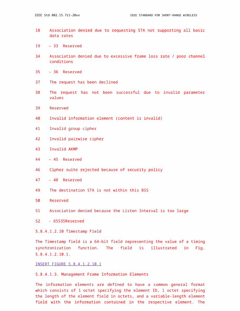
IEEE Std 802.15.7r1-20xx IEEE STANDARD FOR SHORT-RANGE WIRELESS
Figure 191—PSDU field structure
The complete PPDU format for the PHY is shown in Figure 191.
Figure 192—PPDU structure
9.6.6 PHY A PPDU format
9.6.6.1 UFSOOK PPDU format
The UFSOOK PPDU utilizes only the SHR preamble and the PSDU PHY payload (Figure 185). The PHR portion of the PPDU format is not used for UFSOOK.
9.6.6.1.1 UFSOOK Preamble Field
Start frame delimiter consisting of 2 camera video frames of high frequency ON-OFF keying following by 2 camera video frames of UFSOOK mark frequency.
350 Copyright © 20xx IEEE. All rights reserved.

OPTICAL COMMUNICATION IEEE Std 802.15.7r1-20xx
Figure 193—UFSOOK start frame delimiter
9.6.6.1.2 UFSOOK PSDU Field
Arbitrary number of payload bits. The end of the PSDU field is indicated by the presences of another SFD.
9.6.6.2 Twinkle VPPM PPDU format
The Nyquist sampled communications considers the communications to be quasi- synchronous. No effort is made to actually synchronize the receiver timing to the transmitter timing; rather, the preamble is oversam-pled and a down-sampling phase is selected that offers the best performance for the given sample phases.
In order to maximize the throughput, it is required that we minimize the overhead; specifically, we want to keep the SFD and PHR to a minimum length.
9.6.6.2.1 Twinkle VPPM SFD
The SFD is shown in Figure 193.
Figure 194—Twinkle VPPM SFD
Copyright © 2011 IEEE. All rights reserved. 351
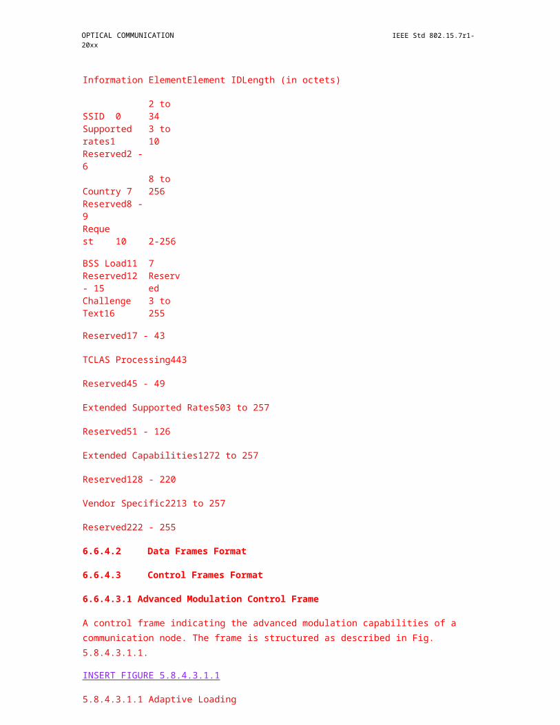
IEEE Std 802.15.7r1-20xx IEEE STANDARD FOR SHORT-RANGE WIRELESS
The SFD for 2/3 duty cycle is 4 symbol times long and consists of 1 symbol of light OFF, followed by 2 symbols of light ON, followed by a 2/3 duty cycle VPPM logic 1.
The SFD for 1/3 duty cycle is 4 symbol times long and consists of 1 symbol of light ON, followed by 2 sym-bols of light OFF, followed by a 1/3 duty cycle VPPM logic 0.
9.6.6.2.2 Twinkle VPPM PHY Header
TBD
9.6.6.2.3 Twinkle VPPM HCS
TBD
9.6.6.2.4 Twinkle VPPM PSDU Field
TBD
9.6.6.3 Offset-VPWM PPDU format
TBD
9.6.6.4 S2-PSK PPDU format
TBD
9.6.6.5 S2+DMS-PSK PPDU format
TBD
9.6.6.6 CSM PPDU format
TBD
9.6.7 PHY B PPDU format
9.6.7.1 RS-FSK PPDU format
Due to convention, the left most field shall be transmitted or received first. All multiple octet fields shall be transmitted or received least significant octet first and each octet shall transmit or receive LSB first as well. The same transmission order should apply to data fields transferred between the PHY layer and the MAC sub-layer. The PPDU frame structure shall be formatted as Figure 194.
Figure 195—Format of the RS-FSK PPDU
352 Copyright © 20xx IEEE. All rights reserved.

OPTICAL COMMUNICATION IEEE Std 802.15.7r1-20xx
9.6.7.1.1 Preamble field
The preamble field is used by the receiver to obtain optical clock synchronization with an incoming mes-sage. This will be the frequency baseline, which is denoted as aPreambleFrequency (check Section 5.1). The frequency used is 2.2 KHz, as specified in section 2.1. The duration of the preamble field is set to be one symbol duration, or 1/30 second (see section 2.2).
The preamble is a time domain sequence and does not have any channel coding or line coding. The same preamble shall be used for all PHY types. The number of repetitions of the preamble field can be extended by the MAC when requested for better synchronization.
9.6.7.1.2 Optional field
Optional field only appears during the synchronization section of the superframe (check section 6.0). Value of the optional field should be specific ratio of the preamble frequency, therefore, the frequency used in the PSDU cannot overlap with the one used in the optional field. If the optional field is assigned, then the data in the PSDU will be, and will only be, the parameter of the field of interest, no data payload can be assigned at the same time.
The optional field shall be formatted as shown in Figure 195. The optional fields are used to indicate that the optional field is required, it should only present its appearance in the synchronization frame (check Section 6.2) of the superframe structure.
The optional field shall be transmitted only when the transmitter informs the receiver about the frequencies used in the data symbols. The optional fields (c) shall be transmitted when one tries to configure the PIB val-ues (check Section 5.0 for more details). Optional field in (b) and (c) shall never be used simultaneously since they correspond to different attributes.
Figure 196—PPDU optional fields
9.6.7.1.3 Gap field
Gap field is a blank field, which is used to indicate the start of the optional field. The frequency used by the gap field is defined as 10 times of the preamble frequency, i.e., 22 KHz. The duration of the field is one sym-bol duration.
9.6.7.1.4 Frequency Labeling field
Frequency labeling field is a value defined precisely at one and a half of the preamble frequency, i.e., 3.3 KHz. This is transmitted for one symbol duration. When this field is transmitted, it indicates the PSDU con-
Copyright © 2011 IEEE. All rights reserved. 353
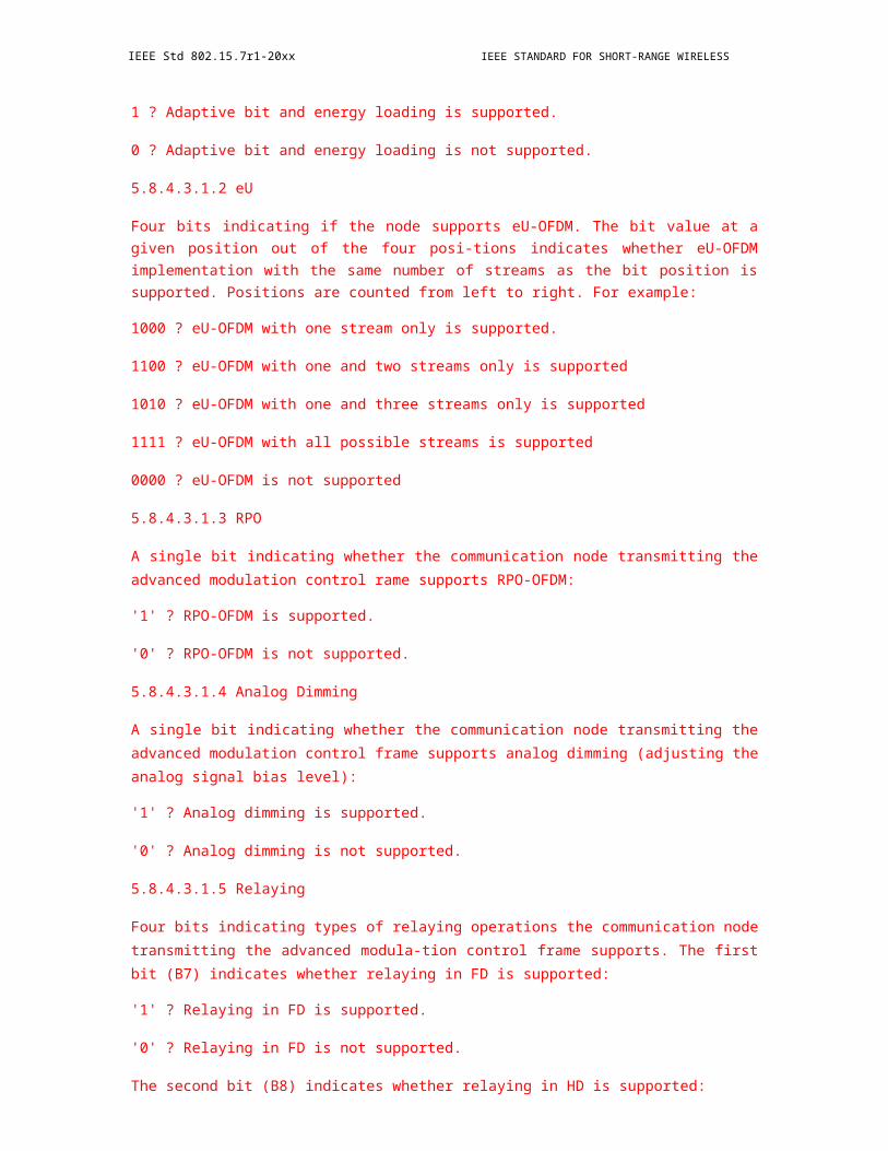
IEEE Std 802.15.7r1-20xx IEEE STANDARD FOR SHORT-RANGE WIRELESS
tains the data frequency that will be used in subsequent transmitted data frames (check Section 6.2), and the PSDU will operate without splitter symbol (check Figure M3).
When transmitting frequency labels, the number of frequencies included in the PSDU should be a power of two. The frequency in the PSDU shall arranged sequentially by the transmitter in ascending order, starting from the frequency representing the smallest bit pattern (i.e., all '0' bit pattern) and ending from with the fre-quency representing the largest bit pattern (i.e., all '1' bit pattern). Consecutive frequency f_i and f_(i+1) should not remain the same. If f_i and f_j are the same, while i?j, the behavior is undefined.
9.6.7.1.5 PIB Attribute field
Directly assign the attribute frequency in this field to assign the value in PSDU field to the receiver, the for-mat is predefined in Section 5.0.
9.6.7.1.6 PSDU field
If splitter symbol is required, the PSDU field has a variable length and carries the data of the PHY frame. The SS (Splitter Symbol) are introduced at the head and tail of each carried DS (Data Symbol) in Figure M. The head and tail SS are still appended if the PSDU has no payload (check Figure M2).
Figure 197—Format of the PSDU
Figure 198—Format of the PSDU without data payload
SS is not necessary if the frame rate is matched between the transceiver and the receiver, this feature can be disabled through the optional field (check Section 4.2.3 for the format, Section 5.0 for all the attributes). In that case, the PSDU field has the format in Figure 198.
354 Copyright © 20xx IEEE. All rights reserved.

OPTICAL COMMUNICATION IEEE Std 802.15.7r1-20xx
Figure 199—Format of the PSDU without SS
Intuitively, when there is no payload, then the PSDU will cease to exist when SS is disabled.
9.6.7.1.7 End Symbol field
This field marks the end of the PPDU, simple but a necessity, in order for the receiver to acknowledge the end of this package. The end symbol frequency is defined as 0.75 times the preamble frequency, i.e., 1.65 KHz, and last for one symbol duration.
9.6.7.2 Kookmin PPDU format and superframe
format 9.6.7.2.1 Super frame
Figure 200—Format of the PPDU
Figure 201—SHR and PHR frame structure
Data frequency: fi = fSF + i.Äf (i=1; 2;…; 32)
Preamble frequency: f’SF = fSF + 33.Äf
Copyright © 2011 IEEE. All rights reserved. 355

IEEE Std 802.15.7r1-20xx IEEE STANDARD FOR SHORT-RANGE WIRELESS
9.6.7.2.2 OOK PPDU frame
Frame type 1: Short frame and non-error detection
Figure 203—Data Packet Structure using a single Ab before and after data part.
Table 95—Our recommendation 1 of parameters
Manchester
3 bit 8 bit
SF Ab Data Ab
OOK: 6 2 8 2
Manchester code (short frame mode)
Frequency 2.2 kHz
DS Packet rate 100 DS/s
Symbol rate 10 symbol/s
PHY SAP data rate 60 bps
Table 96—Manchester code (short frame mode)
Manchester code (short frame mode)
Frequency 2.2 KHz
DS Packet rate 100 DS/s
Symbol 10 symbols
PHY SAP data rate 60 bps
356 Copyright © 20xx IEEE. All rights reserved.
OPTICAL COMMUNICATION IEEE Std 802.15.7r1-20xx
Operation recommendation:
* Frame rate: > 10 fps
* Exposure time: > 10% of (image-frame interval)
Table 97—Our recommendation 2 of parameters
4B6B
6.67 17 bit
SF Ab Data Ab
OOK: 10 26
4B6B code (long frame and none-error detection mode) Frequency 2.2
kHz
DS Packet rate 60 DS/s
Symbol rate 10 symbol/s
PHY SAP data rate 150 bps
Table 98—
4B6B code (long frame and none-error detection mode)
Frequency 2.2 kHz
DS Packet rate 60 DS/s
Symbol rate 10 symbol/s
PHY SAP data rate 150 bps
Operation recommendation:
* Frame rate: > 10 fps
* Exposure time: > 16.7% of (image-frame interval)
Copyright © 2011 IEEE. All rights reserved. 357

IEEE Std 802.15.7r1-20xx IEEE STANDARD FOR SHORT-RANGE WIRELESS
9.6.7.2.3 Frame type 2: Long frame with missing frame (error) detection
Figure 204—Data Packet Structure using couple Ab before and after data part
Figure 206—Detecting missing symbol using asynchronous bits
Our recommendation 3 of parameters:
Table 99—Our recommendation 3 of parameters
Manchester
3 bit 33 bit
SF Ab Data Ab
OOK: 6 4 24 4
358 Copyright © 20xx IEEE. All rights reserved.
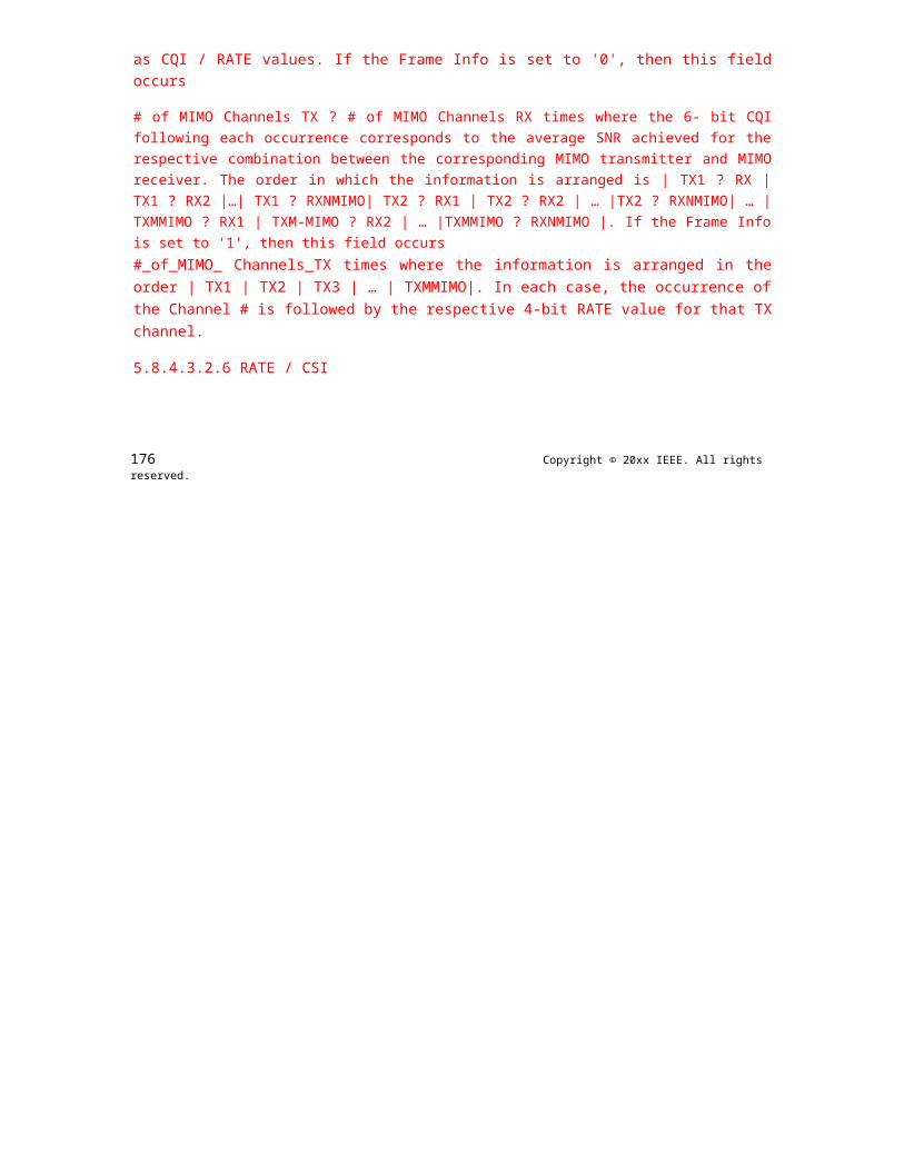
OPTICAL COMMUNICATION IEEE Std 802.15.7r1-20xx
Table 100—Manchester code
Manchester code (long frame with error detection mode)
Frequency 4.4 kHz
DS Packet rate 60 DS/s
Symbol rate 20 symbol/s
PHY SAP data rate 580 bps
Operation recommendation:
* Frame rate: > 20 fps. Any error caused by frame rate drops to less than 20fps can be detected and corrected
* Exposure time: > 33% of (image-frame interval)
Table 101—Our recommendation 4 of parameters
4B6B
41 bit
SF Ab Data Ab
OOK: 10 62
Frequency 4.4 kHz
DS Packet rate 60 DS/s
Symbol rate 20 symbol/s
PHY SAP data rate 70 bps
Table 102—4B6B code (long frame with error detection mode)
4B6B code (long frame with error detection mode)
Frequency 4.4 kHz
DS Packet rate 60 DS/s
Symbol rate 20 symbol/s
PHY SAP data rate 70 bps
Operation recommendation:
* Frame rate: > 20 fps. Any error caused by frame rate drops to less than 20fps can be detected and corrected
Copyright © 2011 IEEE. All rights reserved. 359
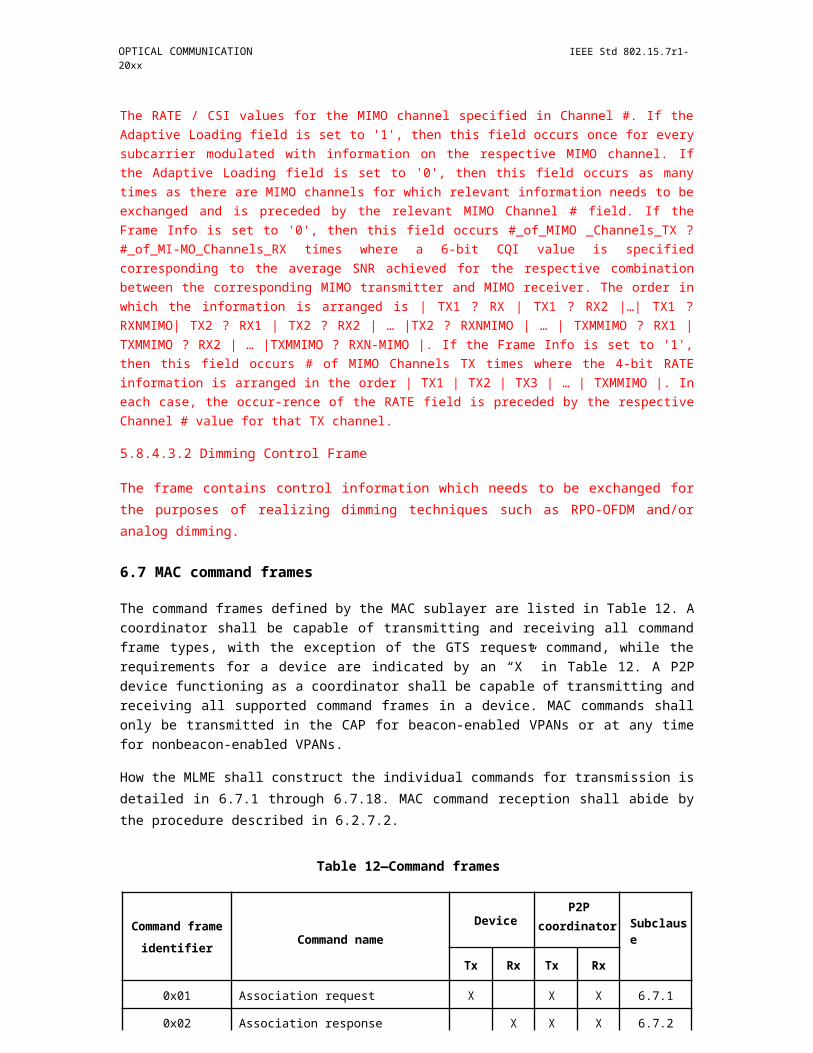
IEEE Std 802.15.7r1-20xx IEEE STANDARD FOR SHORT-RANGE WIRELESS
* Exposure time: > 33% of (image-frame interval)
9.6.7.2.4 FSK PPDU frame
Table: M-FSK modulation of a PPDU frame
Table 103—32-FSK symbol structure
Symbol structure
bits: 1 4
Ab Data packet
Table 104—64-FSK symbol structure
Symbol structure
bits: 1 5
Ab Data packet
Figure 208—PPDU frame
9.6.7.3 FSK PPDU format
TBD
9.6.7.4 2 mode OOK PPDU format
TBD
360 Copyright © 20xx IEEE. All rights reserved.

OPTICAL COMMUNICATION IEEE Std 802.15.7r1-20xx
9.6.7.5 3 mode PWM/PPM PPDU format
TBD
9.6.8 PHY C PPDU format
9.6.8.1 2D-sequential color code PPDU format
TBD
9.6.8.2 Invisible data embedded PPDU format
TBD
9.6.8.3 VTASC PPDU format
TBD
9.6.8.4 PAPM PPDU format
TBD
9.6.8.5 Kookmin Invisible Code PPDU
format 9.6.8.5.1 Reference Architecture
Figure 209—Reference architecture
clock information (of a data packet/symbol): The information represents the state of a symbol clocked out. The clock information is transmitted along with a symbol to help a receiver in identifying an arrival state of new symbol under presence of frame rate variation.
9.6.8.5.2 Transmitter Design
Transmitter Design:
Copyright © 2011 IEEE. All rights reserved. 361
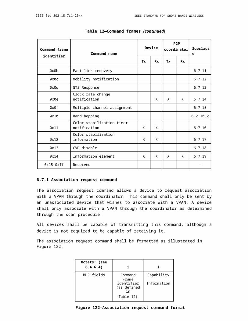
IEEE Std 802.15.7r1-20xx IEEE STANDARD FOR SHORT-RANGE WIRELESS
Figure 210—A design of 16x16 LEDs transmitter
Reference LEDs (4 LEDs at 4 corners):
a) Transmit clock information asynchronous decodingb) To mitigate the rolling shutter effect
4 Surrounding lines (high gradient difference)
a) To help a receiver in detecting and extracting LEDs in real
9.6.8.5.3 Encoder
A proposed 2D-sequential color code
Reference LEDs
Data LEDs
Table 105—A proposed 2D-sequential color code
Reference LEDs Channel Clock information bits (0 1 0 1 ...)
data bit “0” data bit “1”
Data LEDsRed 0 1
Green 0 1
Blue 0 1
362 Copyright © 20xx IEEE. All rights reserved.

OPTICAL COMMUNICATION IEEE Std 802.15.7r1-20xx
Table 106—8-colors encoding truth table
3 bits-input color-output
Figure 212—RGB Venn diagram
An integration of sequential data into a QR-code interface
Copyright © 2011 IEEE. All rights reserved. 363
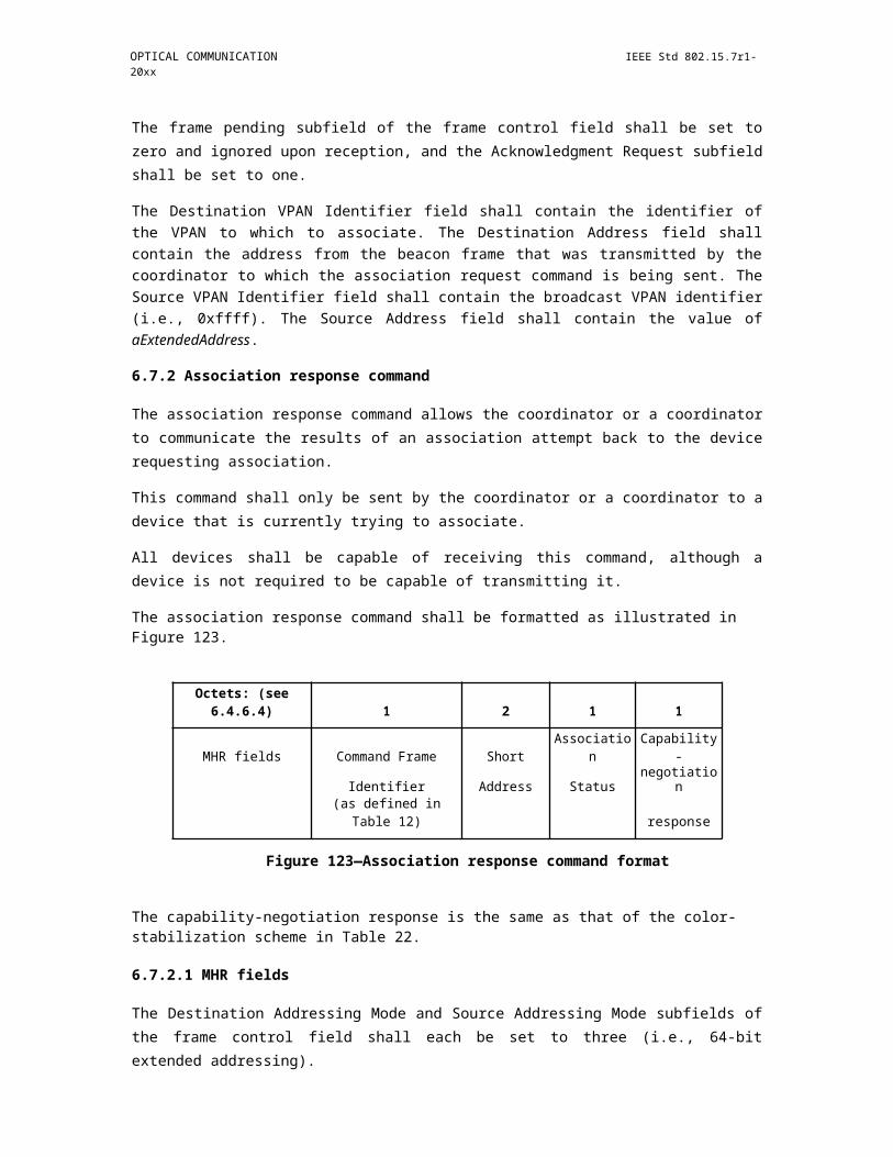
IEEE Std 802.15.7r1-20xx IEEE STANDARD FOR SHORT-RANGE WIRELESS
Figure 213—An integration of sequential data into a QR-code interface
QR-ISC Tag is color modulation in Image Sensor Communications (ISC) integrated into QR code. The ISC uses three channels of Red, Green and Blue to transmit data, along with that is the asynchronous symbols to support varying-frame-rate camera receivers.
a) We borrow the format and error correction from QR code standard.b) An asynchronous bits Inserted is need in helping a varying-frame-rate receiver decoding asynchro-
nously.
9.6.8.5.4 Error Correction
Figure 214—Error correction
a) A spatial Error Correction Coding is need as an inner codeb) Outer code is helpful in correcting any error caused by frame rate drop.
9.6.8.5.5 PHY 6 Layer Decoding Method (for Kookmin color code)
Perspective Distortion Mitigation
364 Copyright © 20xx IEEE. All rights reserved.

OPTICAL COMMUNICATION IEEE Std 802.15.7r1-20xx
Figure 215—LEDs extraction matrix using line detection under perspective distortion
Step 1: 4-Edges detection using image processing
1) Edges are detected by using Hough transform2) The position of 4 corners and matrix positions of LEDs
Step 2: 16x16 LED-positions Matrix forming
a) Input: 4-corner positions Ai(w, h)b) Output: 16x16 matrix of LED-positions
9.6.8.5.6 Rotation Mitigation
Figure 216—Rotation mitigation
a) A blue channel is applied to transmit a signal that allows a receiver in identifying presence of rota-tion.
b) At any time, a state of a reference LED is always different from the other three. The rotation is iden-tified easily by checking those four states of reference LEDs.
Copyright © 2011 IEEE. All rights reserved. 365
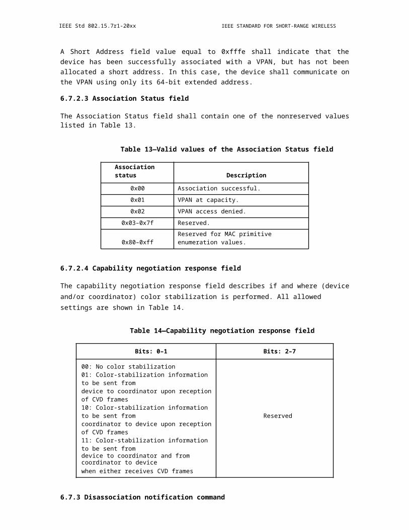
IEEE Std 802.15.7r1-20xx IEEE STANDARD FOR SHORT-RANGE WIRELESS
9.6.8.5.7 Rolling Effect Detection and Cancellation
Figure 217—Rotation matrix
a) q A state-Matrix of 4 reference LEDs at the sample #k: (Notice that the reference signals of those LEDs are transmitted at red channel)
b) Detect the rolling effect in an image:
Figure 218—Rolling effect detection
Notice: The detection is still true under rotation!
9.6.8.5.8 Asynchronous Decoding
This scheme is for helping a receiver in decoding under presence of frame rate variation.
366 Copyright © 20xx IEEE. All rights reserved.
OPTICAL COMMUNICATION IEEE Std 802.15.7r1-20xx
Figure 219—Asynchronous decoding
a) When at least one sample is captured on an interval of a symbol, a majority voting is appliedb) Clock information bit is helpful to identify the group of samples for a symbol voting.
9.6.8.6 VTASC PPDU Format
The PPDU frame structure presented in IEEE802.15.7-2011 (Figure 118 - Format of the PPDU) is shown in Figure 4-1.
Figure 4-1 - Format of the IEEE802.15.7-2011 PPDU
Figure 220—Format of the IEEE802.15.7-2011 PPDU
The IEEE802.15.7r1 PPDU frame structure is formatted as illustrated in Figure 4-2 for PHY-VI 2-Dimen-sional codes
Copyright © 2011 IEEE. All rights reserved. 367
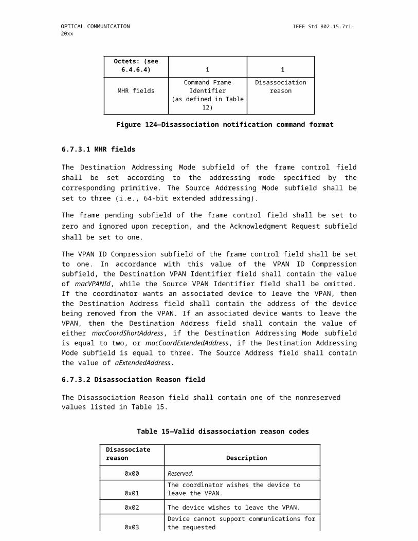
IEEE Std 802.15.7r1-20xx IEEE STANDARD FOR SHORT-RANGE WIRELESS
Figure 221—Format of the IEEE802.15.7r1 PPDU
SHR Field:
The SHR field is used by the transceiver to obtain optical clock synchronization with an incoming message is called Preamble. The standard defines one fast locking pattern (FLP) followed by choice of four topology dependent patterns (TDPs) for the purposes of distinguishing different PHY topologies is shown in Table 4-1.
Table 107—Preamble Pattern with Topologies
TDP Topology Preamble
P1 Topology independt (visibility) 111101011001000
P2 Peer-to-peer 001011101111110
P3 Star 100110000010011
P4 Broadcast 010000110100101
PHR Field:
The IEEE802.15.7r1 PHY header is described as shown in Table 4-2 and shall be transmitted with data to identify the PHY Mode, Data rate, and PSDU length etc. to identify the transmission specification.
Table 4-2 - PHY Header
368 Copyright © 20xx IEEE. All rights reserved.
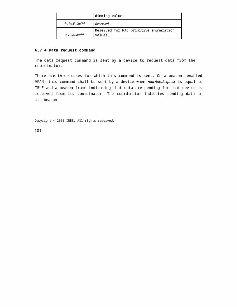
OPTICAL COMMUNICATION IEEE Std 802.15.7r1-20xx
Table 108—PHY Header
PHY header fields Bit-width Explanation on usage
Burst mode 1 Reduce preamble adn IFS
Channel number 3 Band plan ID
MCS ID 6Provide information aboutPHY type and data rate
PSDU length 16Length up to
aMaxPHYFrameSize
Reserved fields 6 Future use
Burst Mode Field: The burst mode bit indicates that the next frame following the current frame is part of the burst mode.
Channel Number Field: The channel number field for PHY shall be the band plan ID of the lowest wave-length.
MCS ID Field: The modulation and coding scheme (MCS) ID shall be indicated in the PHY header based on Table 83.
PSDU Field: The PSDU length field specifies the total number of octets contained in the PSDU.
PSDU Field:
The PSDU field has a variable length and carries the data of the IEEE802.15.7r1 PHY frame. The FCS is appended if the PSDU has a non-zero byte payload. The structure of the PSDU field is as shown in Figure 4-3.
Figure 222—IEEE802.15.7r1 PHY PSDU Field Structure
Copyright © 2011 IEEE. All rights reserved. 369
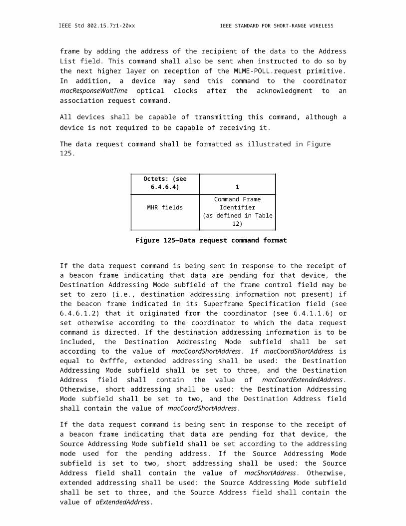
IEEE Std 802.15.7r1-20xx IEEE STANDARD FOR SHORT-RANGE WIRELESS
9.6.9 PHY 7 PPDU format
TBD
9.7 PureLiFi PPDU Format
9.7.1 Frame Structure
The fields of the presented PHY frame are specified in terms of the functionality they are expected to pro-vide. The different parts of the PHY frame structure in Fig. 6.2.1. are envisioned to occupy different OFDM frames in order to achieve a modular PHY frame design, which can be augmented easily based on the func-tionality which the specific PHY implementation supports.
Figure 223—PHY frame structure
Figure 224—Timing parameters for the PHY control information (specification for 20
MHz) 9.7.1.1 Preamble
The function of the preamble is to enable the PHY to identify the existence of a packet and its beginning. The preamble sequence can also be used for signal detection and automatic gain control (AGC). It is speci-fied as the following 160-sample time domain sequence (having the duration equivalent of two OFDM frames). The sequence has been normalized by the factor 1/?66 in order to ensure an average energy level of 1 in the information signal. Four sequences have been defined, where different nodes communicating to each other can adopt different sequences in order to eliminate the possibility for false packet detection due to any cross talk caused by crosstalk between the transmissions in each direction:
370 Copyright © 20xx IEEE. All rights reserved.
OPTICAL COMMUNICATION IEEE Std 802.15.7r1-20xx
S1160 = {0 0 2 -7 - 8 4 9 15 9 -4 -1 -9 - 9 4 9 15 9 -4 - 2 - 10 -8 4 10 14 8 - 4 - 6 5 6 -4 -10 - 15 - 8 4 6 -5 - 6 4 9 15 9 -4 - 1 -9 -9 4 8 15 9 -4 -1 -9 -9 4 9 14 8 -5 -6 4 6 -4 -9 -15 - 9 3 1 9 8 -4 -9 - 15 -9 3 1 9 8 -4 - 9 -15 - 9 4 2 9 8 - 5 -8 -15 -9 4 1 9 8 -4 -10 - 14 - 8 4 6 - 5 -6 4 8 15 9 -4 -2 -10 - 9 4 10 14 8 -4 -7 5 6 -4 -10 -15 -8 4 6 -5 -6 4 10 14 8 -4 -6 4 6 -5 -9 -15 -9 3 1 9 8 -5 -9 -14 -9 4 6 -5 -6 4 10 14 8 -5 -6 5 6 -4 -10 -15}/?66
S2160 = {0 0 -2 7 7 -4 -10 -15 -9 4 6 -5 - 6 4 10 14 8 - 4 - 6 4 6 -4 -9 -15 -9 4 1 9 8 -5 -10 -15 -8 5 6 -5 -6 4 10 14 8 - 4 -7 4 6 -4 -10 - 15 - 8 4 6 -5 - 6 4 8 15 9 -3 -2 - 9 -9 4 10 14 8 -5 -6 5 6 - 4 -9 -15 -9 4 1 9 8 - 5 -9 -15 - 9 4 1 9 8 -5 -8 -15 -9 3 1 9 8 -4 -9 -15 -9 3 2 9 9 -4 -10 -14 -8 4 6 -5 - 6 4 9 15 9 - 4 -2 -9 -8 4 9 15 9 -4 -2 -10 -8 5 9 15 8 -4 -7 5 6 -4 -10 -15 -8 4 6 -5 -6 4 9 15 9 -3 -2 -9 -9 4 9 15 9 -4 -2 -10 -8 4 9 15}/?66
S3160 = {0 0 -2 7 7 -5 -9 -15 - 10 4 1 9 8 -5 -9 -15 - 9 4 1 8 8 -4 -8 -15 -9 4 1 9 8 -4 -10 - 14 -8 4 6 -5 -6 4 9 14 8 -5 -6 5 6 -4 - 10 -15 -9 4 6 - 5 -7 4 10 15 8 -5 -7 5 6 -4 -10 -15 -8 4 6 -5 -7 4 8 15 10 -4 -1 -9 -8 4 8 15 9 -3 -1 -9 -9 4 9 15 9 -3 -2 -9 -8 4 9 14 8 -4 -6 4 6 -4 -9 -15 - 9 3 1 9 8 - 5 - 9 -15 -8 4 6 -4 -6 4 9 15 10 -4 -1 -10 -8 5 10 14 8 -4 -6 4 6 -5 -10 -15 -8 4 6 -5 -7 4 9 15 9 -4 -1 -9 -8 4 10 14 8 -5 -6 5 6 -4 -10 -15}/?66
S4160 = {0 0 -2 7 7 -4 -9 -15 - 8 4 6 -5 - 6 4 9 15 9 -4 - 2 - 10 -9 4 10 15 8 -4 -6 4 6 - 4 -10 -14 -8 4 6 -5 -6 4 9 15 9 -4 -2 -10 -9 4 9 14 8 - 4 -6 4 6 -5 -9 -15 -9 4 1 9 8 -4 -9 -14 -8 4 6 -5 -6 4 9 15 9 -3 -2 -9 -8 4 9 15 9 -4 - 2 -9 -9 4 9 15 9 -4 -2 -9 -9 4 9 14 8 -5 -6 4 6 -4 -10 -14 -8 4 6 -5 -6 4 10 14 8 -4 -7 5 6 -4 -10 -15 -9 4 6 -5 -6 4 9 14 7 -4 -6 5 6 -4 -9 -15 -9 3 1 9 8 -5 -8 -15 -9 4 1 9 8 -5 -9 -15 -9 3 1 9 8 -5 -10 -15}/?66
The time -domain cross- correlation of the specified preamble delivers an easily-identifiable sharp peak value which is expected to be used for packet detection and synchronization.
9.7.1.2 Channel Estimation
A sequence of two identical OFDM training symbols is used to estimate the channel impulse response. The sequence can also be used for additional fine-timing synchronization. The channel estimation sequence con-tains the following values modulated on the subcarriers of two identical OFDM frames (index 0 corresponds to the DC subcarrier modulation value):
E0 to 63 = {0 0 0 -1 -1 1 -1 1 - 1 -1 1 1 1 -1 - 1 -1 1 -1 1 1 1 1 1 -1 -1 1 1 -1 1 0 0 0 0 0 0 0 1 -1 1 1 -1 -1 1 1 1 1 1 -1 1 -1 -1 -1 1 1 1 -1 -1 1 -1 1 -1 -1 0 0}
The sequence is Hermitian symmetric in order to satisfy the requirement for a real time-domain signal after the IDFT and has very good auto-correlation properties. In Fig. 6.2.2, the channel estimation OFDM symbol is transmitted twice in two identical copies of the time-equivalent signal of the frequency-domain modula-tion sequence E0 to 63. The time-domain signal is obtained after an IDFT operation on E0 to 63. The guard interval GI2 is a cyclic extension of this same time-domain signal and has a duration of 32 samples (twice the length of the typical cyclic extension for this PHY mode specification).
Copyright © 2011 IEEE. All rights reserved. 371
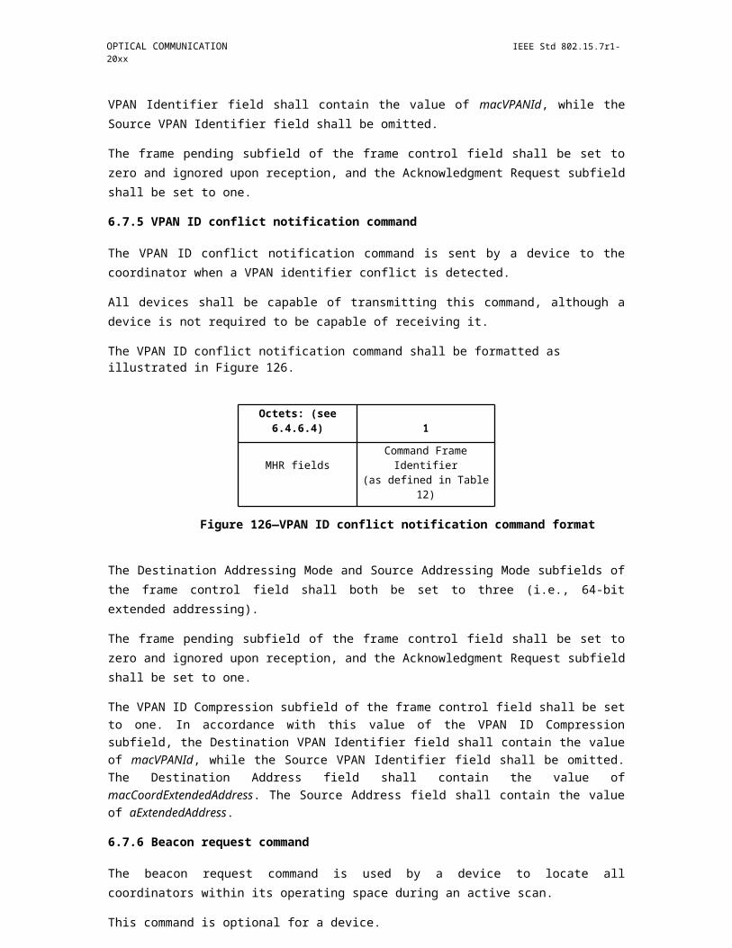
IEEE Std 802.15.7r1-20xx IEEE STANDARD FOR SHORT-RANGE WIRELESS
9.7.1.3 Header
The Header contains all information necessary for demodulating the subsequent frame payload. It is always encoded in 1/2 FEC rate BPSK modulation using DCO-OFDM. The header is logically split into three sec-tions, which are encoded in separate OFDM frames (each part may be encoded in more than one OFDM frame) in order to achieve a modular PHY frame design.
The two components of the header in the current PHY take the following form.
9.7.1.3.1 Basic Header
The basic header contains the minimum information required for demodulating the subsequent payload. In the low -bandwidth PHY mode, this header includes information such as the constellation size, the FEC rate and the payload size. The Basic Header also indicates whether an Advanced Modulation Header (containing further information regarding the modulation format) is used. If no advanced modulation header is used, then the DATA portion of the PHY frame is expected to appear after the basic header. The basic header con-tains 24 bits and fits within 2 OFDM frames of the current PHY mode. The field contains the information and is structured as depicted in Fig. 6.2.3.1.1.
Figure 225—Structure of the Basic Header
The individual fields of the basic header are described as follows.
6.2.3.1.1. RATE
The RATE field consists of three bits and indicates the QAM constellation size and the FEC rate (achieved with the use of a convolutional encoder and puncturing) used for the subsequent payload. The values speci-fied in Table 5 are valid for the RATE field.
Insert Table 6.2.3.1.1.1: Valid RATE values
6.2.3.1.2. Reserved bits (R)
One bit is reserved for introducing additional transmission rates in future modifications of the standard.
6.2.3.1.3. LENGTH
372 Copyright © 20xx IEEE. All rights reserved.
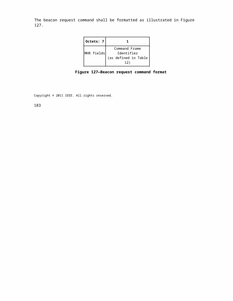
OPTICAL COMMUNICATION IEEE Std 802.15.7r1-20xx
An 11-bit field which indicates the size of the payload in octets. Hence, the size of the payload is between 0 and 2048 octets.
6.2.3.1.4. Advanced Modulation Header Bit (A)
One bit indicating whether an Advanced Modulation Header is included in the next OFDM frame:
1 ? The next OFDM frame is an Advanced Modulation Header.
0 ? The next OFDM frame is part of the DATA portion (payload) of the PHY frame.
6.2.3.1.5. High-reliability MAC Header Bit (M)
One bit indicating whether a high-reliability MAC header encoding is used. If the advanced modulation header is not enabled, then the next OFDM frame encodes the high-reliability MAC header described in sub-clause 6.2.5.1.
1 ? The OFDM frame following the advanced modulation header is part of the high-reliability
MAC header encoding.
0 ? The OFDM frame following the advanced modulation header is part of the conventional DATA
portion (payload) of the PHY frame encoding using the RATE specified in subclause
6.2.3.3.1.1.
6.2.3.1.6. Parity Check Bit (P)
An even parity check bit for the information in bits 0 - 16.
6.2.3.1.7. SIGNAL TAIL
Six bits set to zero complete the Basic Header. These bits re-set the state machine of the convolutional encoder used in the current PHY mode.
Copyright © 2011 IEEE. All rights reserved. 373
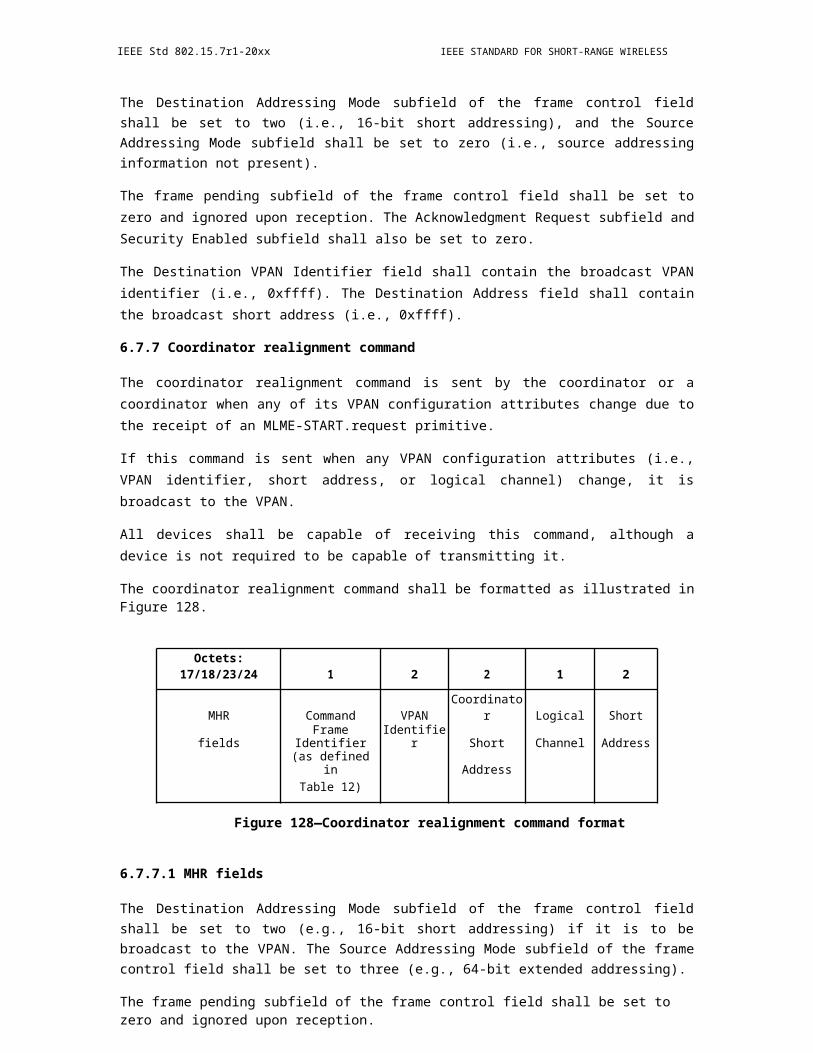
IEEE Std 802.15.7r1-20xx IEEE STANDARD FOR SHORT-RANGE WIRELESS
9.7.1.3.2 Advanced Modulation Header
The advanced modulation header is encoded in separate OFDM frames from the Basic Header, so that the overall structure is modular, i.e., when the advanced modulation header is not required, it can be easily excluded. Like the basic header, the advanced modulation header is encoded using 1/2 FEC rate BPSK. The advanced modulation header is an optional field which contains the information necessary for demodulating the subsequent waveform. It contains information necessary to identify if adaptive bit and energy allocation is used. It also contains commands for the PHY necessary for estimating the channel quality indicators (CQIs), necessary for enabling adaptive bit and energy loading during the real-time operation of the system. The format is presented in Fig. 6.2.3.2.1.
Figure 226—Advanced Modulation Header format
6.2.3.2.1. Adaptive Bit Loading Use (B)
One bit indicating whether adaptive bit loading is used to encode the subsequent payload:
1 ? Adaptive bit loading is used. In this case, the subsequent payload is encoded with the loading
scheme which the receiving station has estimated and suggested to the transmitter using the
feedback channels and negotiation procedures in the MAC layer.
0 ? Adaptive bit loading is not used. In this case, the subsequent payload is encoded with the
default loading scheme and the rate specified in the Basic Header.
The low-bandwidth PHY mode is not required to support adaptive bit loading. If a PHY which does not sup-port bit loading encounters a packet which has this bit set to 1, it will ignore the packet, as it will no be able to demodulate it.
6.2.3.2.2. Estimate CQIs (C)
One bit indicating whether the CQIs should be calculated in the PHY for the current transmission frame. The channel estimation symbols preceding the PHY header are used for the estimation of the CQIs if the MIMO mode is not enabled. If the MIMO mode is enabled, the MIMO reference symbols described in 6.2.4.
374 Copyright © 20xx IEEE. All rights reserved.
OPTICAL COMMUNICATION IEEE Std 802.15.7r1-20xx
1 ? the CQIs should be estimated
0 ? the CQIs should not be estimated
Upon estimation of the CQIs, the PHY conveys the results to the MAC using a predefined PHY service primitive. The calculation of the bit and power allocation scheme as well as the necessary exchange for updating the bit and power allocation scheme at the transmitter and receiver are handled at the MAC layer.
6.2.3.2.3. Use of eU-OFDM (eU)
Indicates whether the PHY DATA (payload) field is encoded using eU-OFDM.
1 ? the DATA (payload) is encoded using eU-OFDM.
0 ? the DATA (payload) is not encoded using eU-OFDM.
Note that the use of this alternative waveform can be negotiated in advance using control/management frames. Furthermore, the use of eU-OFDM encoding does not prohibit the use of any additional advanced waveforms such as SC-FDMA or RPO-OFDM.
6.2.3.2.4. Number of Streams in eU-OFDM (STR)
Two bits indicating the number of U-OFDM streams superimposed in the signal encoding procedure. The valid values for this field are:
Insert Table 6.2.3.2.5.1: Valid STR values
6.2.3.2.5. Use of Single-carrier FDMA
Indicates whether the PHY DATA (payload) field is encoded using SC-FDMA.
1 ? the DATA (payload) is encoded using SC-FDMA.
0 ? the DATA (payload) is not encoded using SC-FDMA.
Copyright © 2011 IEEE. All rights reserved. 375
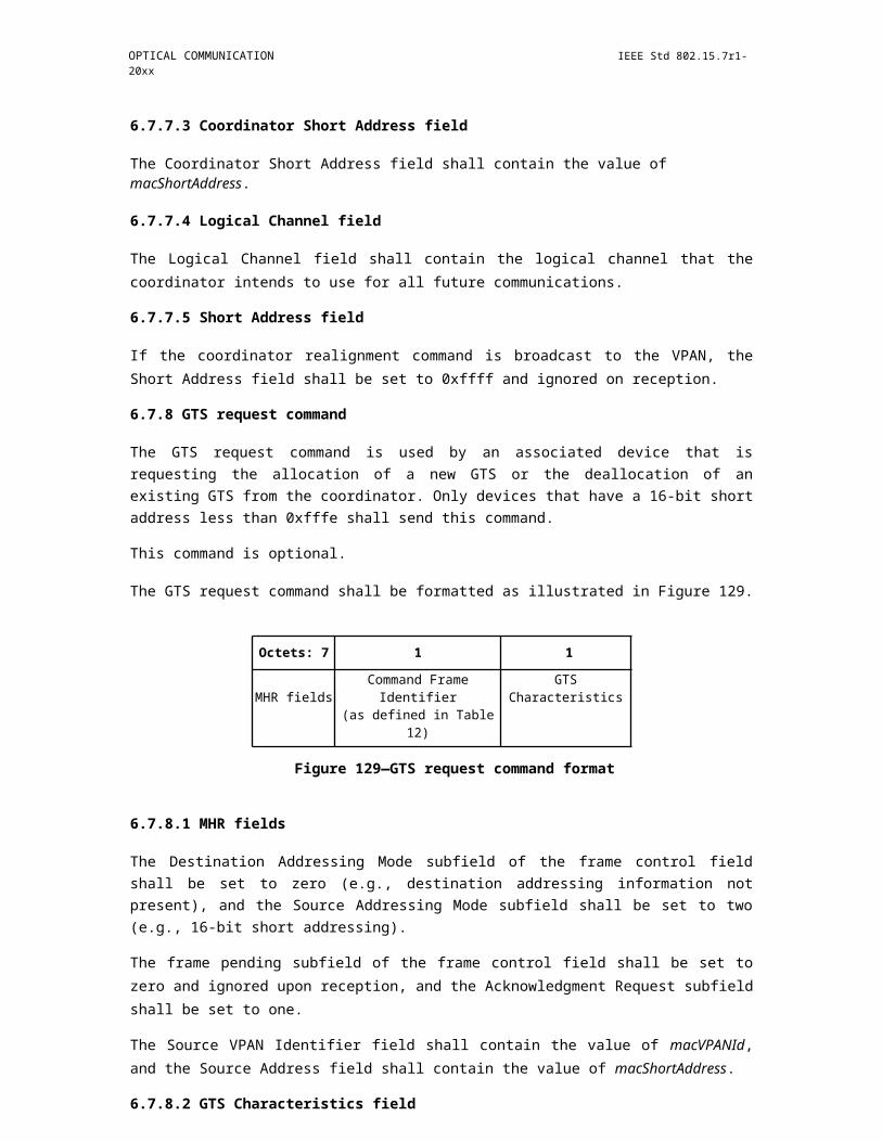
IEEE Std 802.15.7r1-20xx IEEE STANDARD FOR SHORT-RANGE WIRELESS
Note that the use of this alternative waveform can be negotiated in advance using control/management frames. Furthermore, the use of SC-FDMA encoding does not prohibit the use of any additional advanced waveforms such as eU-OFDM or RPO-OFDM.
6.2.3.2.6. SC-FDMA pre-coder DFT Size (DFT)
A number specifiying the DFT size used in the SC-FDMA pre-coding procedure. As only 24 subcarriers are modulated with unique data, the DFT size is a number between 1 and 24.
6.2.3.2.7. Number of Reverse Polarity Optical OFDM frames (NRPO)
Indicates the number of OFDM data frames which are encoded using RPO -OFDM as described in subclause 6.3.8. By convention, the LSB of this number is transmitted first. A value of NRPO='000000' indicates that RPO-OFDM is not used.
Note that the use of this alternative waveform can be negotiated in advance using control/management frames. Furthermore, the use of RPO-OFDM encoding does not prohibit the use of any additional advanced waveforms such as eU-OFDM or SC-FDMA.
6.2.3.2.8. Signal scaling factor in Reverse Polarity Optical OFDM frames (GRPO)
Indicates the factor by which the OFDM data signal is scaled as described in subclause 6.3.8. If NRPO='000000', this field is not relevant for the signal transmission.
6.2.3.2.9. Relaying Operation Enabled (RE)
1 ? Relaying should be performed for the current PHY frame.
0 ? Relaying should not be performed for the current PHY frame.
6.2.3.2.10. Relaying Operation Type (RT)
376 Copyright © 20xx IEEE. All rights reserved.
OPTICAL COMMUNICATION IEEE Std 802.15.7r1-20xx
Two bits which specify the type of relaying operation that should be performed. The valid values for this field are specified as:
Insert Table 6.2.3.2.10: Valid RT values
6.2.3.2.11. MIMO Enable Bit (M)
One bit indicating whether a MIMO mode is enabled for the current PHY frame:
1 ? MIMO mode is enabled and the subsequent payload is encoded using the MIMO
scheme already negotiated by the transmitter and the receiver.
0 ? MIMO mode is not enabled and the subsequent payload is encoded using the SISO scheme
specified by the parameters in the basic header and the advanced modulation header.
6.2.3.2.12. MIMO Reference Symbols Format (RS)
One bit which indicates the format of the reference symbols used for CQI
estimation. 1 ? MIMO Reference Symbols Format I is used.
0 ? MIMO Reference Symbols Format II is used.
The two MIMO reference symbols formats are specified in 6.2.4.
6.2.3.2.13. Parity Check Bit (P)
An even parity check bit for the information in bits 0 - 16.
6.2.3.2.14. SIGNAL TAIL
Six bits set to zero complete the advanced modulation header. These bits re-set the state machine of the con-volutional encoder used in the current PHY mode.
6.2.4. MIMO Reference Symbols (RSs)
Copyright © 2011 IEEE. All rights reserved. 377

IEEE Std 802.15.7r1-20xx IEEE STANDARD FOR SHORT-RANGE WIRELESS
Figure 227—High-reliability MAC header structure
The MIMO reference symbols constitute NMIMO OFDM frames (or the time- frame equivalent of NMIMO OFDM frames), where NMIMO = number of MIMO channels. Depending on the reference symbol format in use, the bit RS is set to '0' for reference symbols format I and set to '1' for reference symbols format II. The symbol formats are described as follows.
9.7.1.4 Data
The Data field contains the MPDU transferred from the higher layer. The size of this field is specified in the basic PHY header. The MPDU is encoded according to the modulation format specified in the PHY header. The Data field contains a Service field, a MAC header portion of the MPDU encoded in the most robust modulation format, as well as the remaining portion of the MPDU complemented with a TAIL field and pad-ding bits, which extend the length of the field to an integer number of OFDM frames.
9.7.1.4.1 High-reliability MAC Header
Robust transmission of the polling and acknowledgement information ensures avoiding a lot of unnecessary retransmissions. Furthermore, when this information is encoded separately from the rest of the payload, errors in the payload (especially for long payloads) which cause the packet to be discarded (and retransmit-ted) do not influence the polling and acknowledgement mechanism. As a result, the MAC header (the part of the header required for polling and acknowledgments) is encoded in a special high- reliability header using the lowest data-rate (most robust) modulation format 1/2 FEC rate BPSK separately from the data payload. The high-reliability MAC header has the structure described in Fig. 6.2.5.2.1.
6.2.5.1.1. Protocol Version
The first two bits of the MAC frame indicating the MAC protocol version. If an incompatible MAC frame version is encountered in this frame, the PHY will drop the rest of the packet and signal an incompatible MAC protocol version to the MAC layer management entity.
6.2.5.1.2. Polled station number
378 Copyright © 20xx IEEE. All rights reserved.

OPTICAL COMMUNICATION IEEE Std 802.15.7r1-20xx
In the downlink transmission, this field specified the number of the station which is being polled by the access point. On the uplink, these bits are left unspecified.
6.2.5.1.3. Packet sequence number
A twelve-bit number which specifies the sequence number of the packet that is being acknowledged.
6.2.5.1.5. Acknowledgement (ACK)
A two-bit field which enables the AP and the stations to acknowledge packet reception as well as beacon reception. Bit 30 is set to '1', when a transmitting node (station or access point) is acknowledging the recep-tion of the packet with the sequence number specified by the field described in 6.2.5.1.3. Bit 31 is set to '1', when a station is acknowledging the reception of a beacon frame, indicating it is still active and connected to the AP.
6.2.5.1.6. Reserved bits (R)
Nine bits (at positions 32-40) are reserved for future use. Hence, they have not been specified.
6.2.5.1.7. Parity check bit (P)
An even parity check bit for the information in bits 0 - 40.
6.2.5.1.8. SIGNAL TAIL
Six bits set to zero complete the high-reliability MAC header. These bits re-set the state machine of the con-volutional encoder used in the current PHY mode.
Copyright © 2011 IEEE. All rights reserved. 379
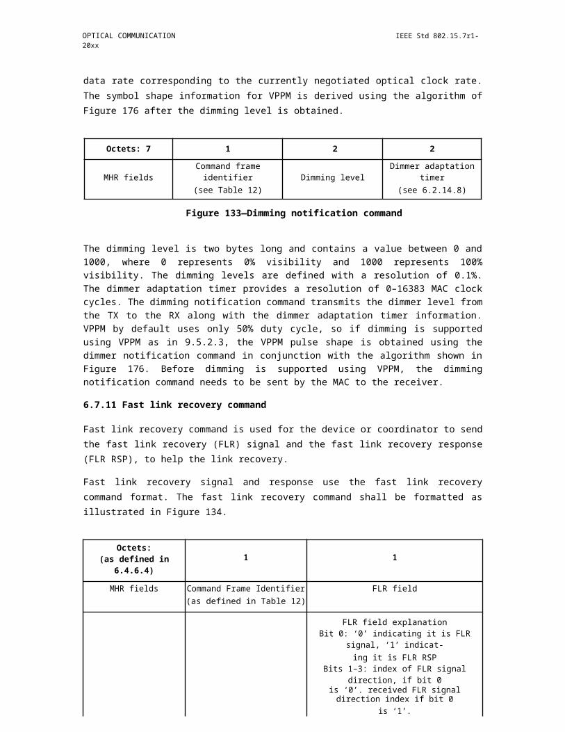
IEEE Std 802.15.7r1-20xx IEEE STANDARD FOR SHORT-RANGE WIRELESS
9.7.1.4.2 Service Field
The Service field has 16 bits, which shall be denoted as bits 0-15. The bit 0 shall be transmitted first in time. The bits from 0-6 of the SERVICE field, which are transmitted first, are set to zeros and are used esti-mate the initial state of the transmitter scrambler and to synchronize the descrambler in the receiver. The remaining 9 bits (7-15) of the SERVICE field shall be reserved for future use. All reserved bits shall be set to 0. Refer to Figure 6.2.5.2.1.
Figure 228—SERVICE field bit assignment
9.7.1.4.3 General Payload Data
The general payload is encoded according to the modulation format specified in the PHY header. This field contains the MPDU transferred from the higher layer except for the parts of the MAC Header already encoded in the high-reliability MAC header as described in 6.2.5.2. followed by a tail field of six zero bits necessary to reset the convolutional encoder and a four-byte frame check sequence. In case the DATA field does not fit within an exact number of OFDM frames, padding bits are introduced.
6.2.5.3.1. Tail Field
The PPDU TAIL field shall be six zero bits, which are required to return the convolutional encoder to the zero state. This procedure improves the error probability of the convolutional decoder, which relies on future bits when decoding and which may not be available past the end of the message. The PLCP tail bit field shall be produced by replacing six scrambled zero bits following the message end with six nonscrambled zero bits.
6.2.5.3.2. Padding Bits
The number of bits in the DATA field shall be a multiple of NCBPS, the number of coded bits in an OFDM symbol (24, 48, 96, or 144 bits). To achieve this, the length of the message is extended so that it becomes a multiple of NDBPS, the number of data bits per OFDM symbol. At least 6 bits are appended to the message, in order to accommodate the TAIL bits, as described in 3.5.2. The number of OFDM symbols, NSYM; the
380 Copyright © 20xx IEEE. All rights reserved.
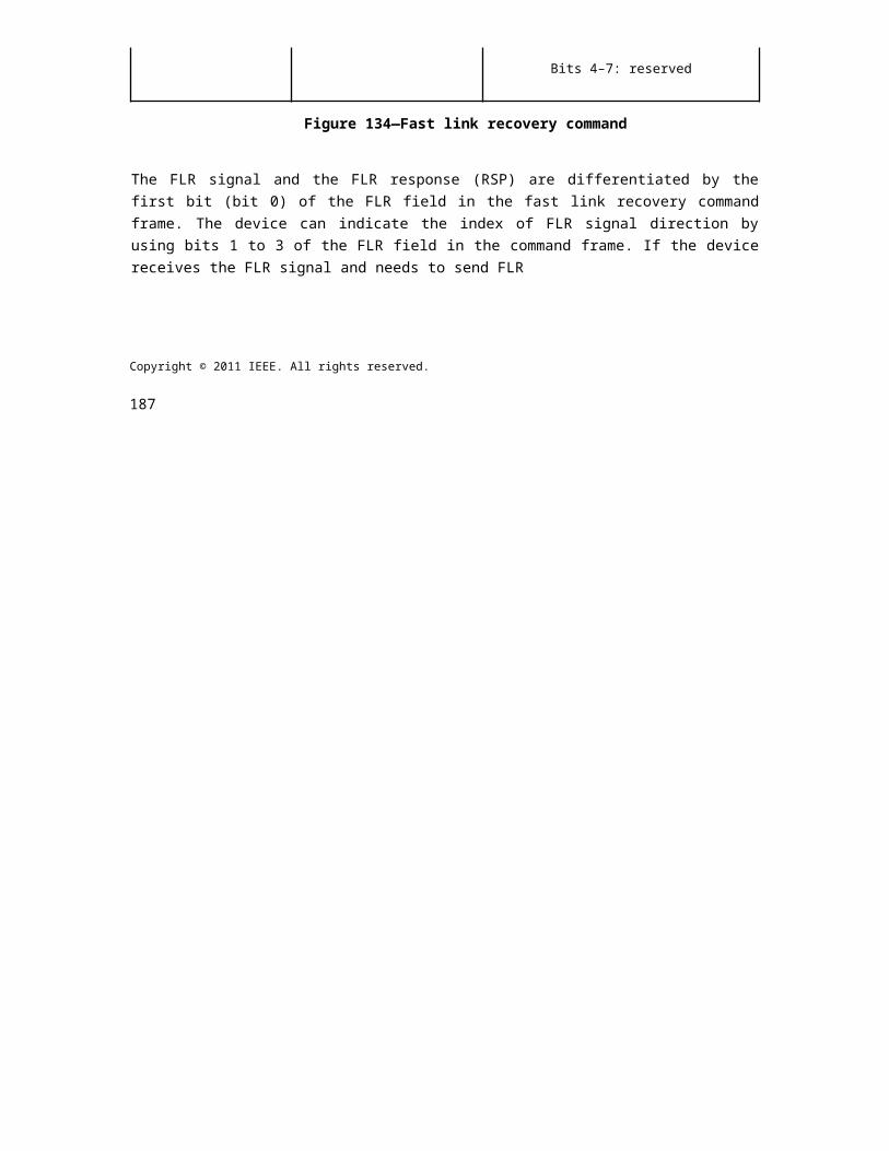
OPTICAL COMMUNICATION IEEE Std 802.15.7r1-20xx
number of bits in the DATA field, NDATA; and the number of pad bits, NPAD, are computed from the length of the PSDU (LENGTH) as follows:
NSYM = Ceiling ((16 + 8 × LENGTH + 6)/NDBPS) (1)
NDATA = NSYM × NDBPS (2)
NPAD = NDATA - (16 + 8 × LENGTH + 6) (3)
Figure 229—Data Scrambler / Descrambler
The function Ceiling (.) is a function that returns the smallest integer value greater than or equal to its argu-ment value. The appended bits ("pad bits") are set to zeros and are subsequently scrambled with the rest of the bits in the DATA field.
6.2.5.3.3. Data scrambler and descrambler
The DATA field, composed of SERVICE, PSDU, tail, and pad parts, shall be scrambled with a length -127 frame-synchronous scrambler. The octets of the PSDU are placed in the transmit serial bit stream, bit 0 first and bit 7 last. The frame synchronous scrambler uses the generator polynomial S(x) as follows, and is illus-trated in Figure 6.2.5.3.3.1:
S(x) = x7 + x4 + 1 (4)
The 127-bit sequence generated repeatedly by the scrambler shall be (leftmost used first), 00001110 11110010 11001001 00000010 00100110 00101110 10110110 00001100 11010100 11100111 10110100 00101010 11111010 01010001 10111000 1111111, when the all ones initial state is used. The same scram-bler is used to scramble transmit data and to descramble receive data. When transmitting, the initial state of the scrambler will be set to a pseudo -random nonzero state. The seven LSBs of the SERVICE field will be set to all zeros prior to scrambling to enable estimation of the initial state of the scrambler in the receiver.?
Copyright © 2011 IEEE. All rights reserved. 381
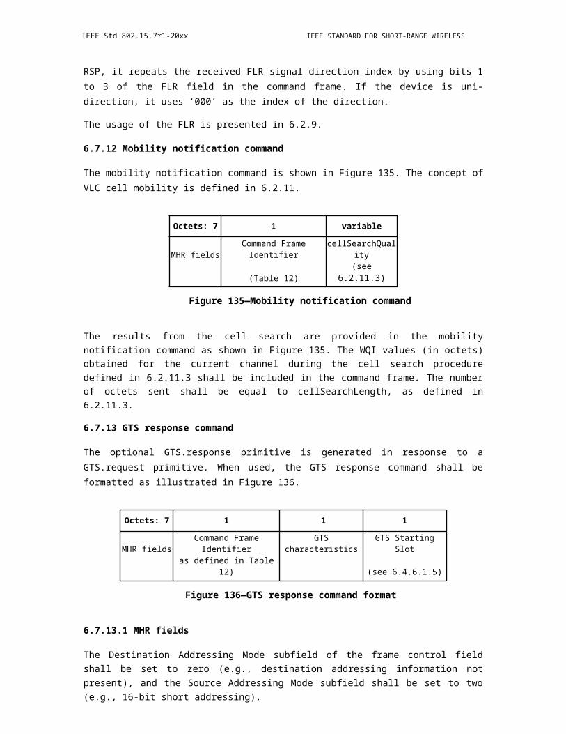
IEEE Std 802.15.7r1-20xx IEEE STANDARD FOR SHORT-RANGE WIRELESS
9.8 Fraunhofer PPDU Format
9.9 Frame structure
The data signal, denoted as payload in Figure 4-1, is transmitted together with additional signals in a com-pound frame, so that the payload can be decoded frame- wise. The preamble is followed by a PHY header. The preamble allows coarse time synchronization in its first two parts, followed by a reference sequence used for fine timing as well as channel estimation, what enables the receiver to decode the header informa-tion. After the header, eventually there are additional channel estimation (ACE) symbols, basically needed for the support of multiple-input multiple-output (MIMO), before the payload is then transmitted. In case of using MIMO in 802.15.7r1, all transmitters transmit the same preamble and header information, while only the payload makes explicit use of MIMO. The ACE symbols contain an orthogonal sequence of symbols (same symbols but with alternate signs) in order to estimate the MIMO channel.
Figure 230—P2P PHY frame, taken over from G.hn specification
Figure 5-1 - P2P PHY frame, taken over from G.hn specification.
9.9.1 Frame types
By using the same frame structure, the PHY can transport different frame types. An overview is provided in Table 4-1.
Insert Table 4-1 -PHY frame types. The basic frame types are highlighted using bold letters. here
9.9.2 Preamble
The preamble is prepended to a PHY frame and is intended for frame detection/synchronization, initial channel estimation and OFDM symbol alignment. It may be used for recovery of the following header seg-ment of the PHY frame.
The preamble is divided into three sections; each consists of a repetition of N_n OFDM symbols S_n, where the subscript n=1,2,3 denotes the section. Each S_n is output by the IFFT. The inputs of the IFFT, i.e. com-plex valued symbols, are generated by feeding into the constellation scrambler described in 2.2.2.7.2 a con-stant series of 1s. The three sections are windowed and combined additively as outlines in Figure 4-2.
382 Copyright © 20xx IEEE. All rights reserved.
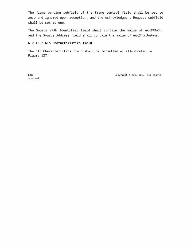
OPTICAL COMMUNICATION IEEE Std 802.15.7r1-20xx
Figure 231—Preamble structure
In the default case, every k _n-th subcarrier is used, starting from the subcarrier index i=0. For n=3, the used subcarrier spacing k_n and the LSFR seed differs from the cases in which n=1,2 as described in Table 4-2.
Insert Table 4-2 - Default properties of preamble sub-sequences here
9.9.3 Channel estimation
The final OFDM symbol in the preamble is used for channel estimation. It is useful to detect the header information and when using single-input single-output (SISO) transmission, it can also be used for the detection of data. In case MIMO is used additional channel estimation (ACE) symbols are used for channel estimation. These additional symbols are sent after the header, as part of the data block in the frame.
9.9.4 PHY frame header
The PHY-frame header always fits into an integer number of OFDM symbols and is transmitted using a sin-gle, predefined set of modulation and coding parameters. i.e. 1 bit/symbol with code rate ½. The core part of the PHY-frame header is 168 bits long. It is composed of a common part and a variable part. The fields of the PHY-frame header are defined in the following table.
Insert table from 16/356r0, clause 5.1.4, here
The common part contains fields that are common for all PHY-frame types. The variable frame-type specific field (FTSF) part contains fields according to the PHY-frame type. The content of the core part is protected by the 16-bit header check sequence (HCS).
9.9.4.1 Common part fields of the PHY-frame header
The frame type (FT) field is a 4-bit field that indicates the type of PHY frame.
The domain ID (DOD) field contains the domain ID to which the source and destination devices of the PHY frame belong. It is represented as a 4-bit unsigned integer with valid values in the range from 0 to 15. Value 0 is a special value reserved for inter-domain communication.
Copyright © 2011 IEEE. All rights reserved. 383
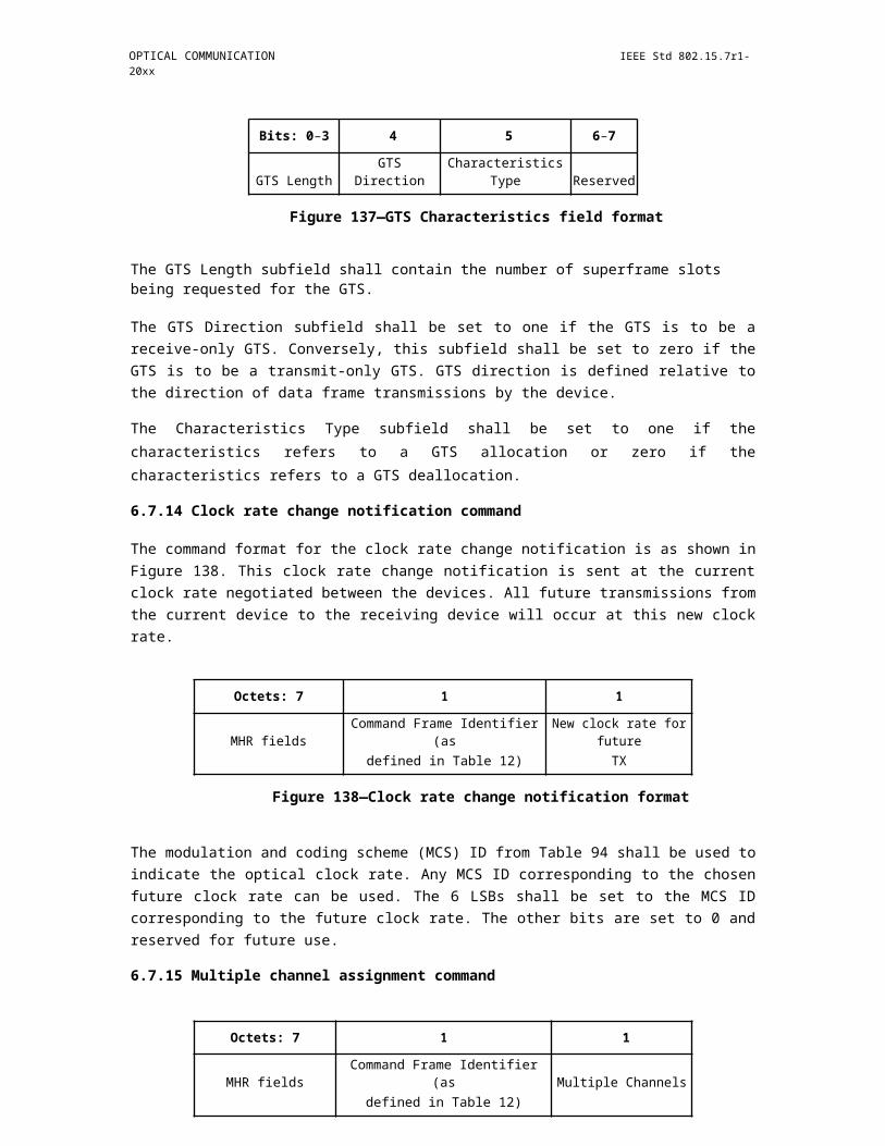
IEEE Std 802.15.7r1-20xx IEEE STANDARD FOR SHORT-RANGE WIRELESS
The destination ID (DID) field identifies the destination node(s) of the PHY frame. It is represented as an 8-bit unsigned integer with valid values in the range from 0 to 250.
If the multicast indication (MI) bit is set to zero, the DID field shall contain the DEVICE_ID of the destina-tion node (for unicast transmission). If the MI bit is set to one, the DID field shall contain a MULTICAST-_ID or BROADCAST_ID of the destination nodes.
If the duration indication (DRI) bit is set to zero, the PHY frame shall not contain any payload (i.e., contains only preamble and PHY-frame header). If the DRI bit is set to one, the FTSF shall start with a duration field. The duration field contains the duration of a single PHY frame or PHY frame sequence. It shall be repre-sented as a 16-bit unsigned integer with valid values in steps of 0.25 ?s. It shall be the smallest integer larger than or equal to the actual duration.
If the extended header indication (EHI) field is set to zero, the PHY-frame header shall contain 168 informa-tion bits. If it is set to one, the PHY frame header shall contain 2×168 information bits. The EHI field shall be set according to the frame type as shown in Table 4-1.
The header check sequence (HCS) field is intended for PHY-frame header verification. It is a 16-bit cyclic redundancy check (CRC) and shall be computed over all the fields of the PHY-frame header in the order they are transmitted, starting with the LSB of the first field of the PHY frame header (FT) and ending with the MSB of the last field of the FTSF. The HCS is computed using the following generator polynomial of degree 16
G(x) = x16 + x12 + x5 + 1
The value of the HCS is the remainder after the contents (treated as a polynomial where the first input bit is associated with the highest degree, X168-17, where 168 is the header length in bits, and the last input bit is associated with X0 of the calculation field is multiplied by x16 and then divided by G(x). The HCS field is transmitted starting with the coefficient of the highest order term.
9.9.4.1.1 Variable part fields of the PHY-frame header
The ITU-T recommendation G.9960-2015 contains a very detailed description of the variable frame-type specific field (FTSF) in the PHY-frame header. Here, only the main parameters in each frame type are explained.
The medium access plan (MAP) and relayed MAP (RMAP) PHY frames are used to schedule transmission opportunities among the devices in a direct or relayed transmission. The FTSF of MAP and RMAP frames contains the duration of the MAP frame, the network time reference, i.e. the start of the first OFDM symbol of the preamble with 10 ns resolution. The start time of the next MAC cycle, the size of repetition blocks, scrambler initialization value, the information block size of the FEC code word used for the payload, the number of repetitions used for encoding the data, the concatenation factor in the FEC, the band plan which contains the used bandwidth for this frame. The MAP type indicates what kind of bit allocation table is used for the bitloading of the payload. Finally, the type of MAP or RMAP transmission is indicated and the num-ber of hops from the master domain.
The data and management frame (MSG) is used to carry user data or management data or both. The parame-ters in the MSG frame are the duration of the MSG frame, the information block size of the payload, code rate, number of repetitions, concatenation factor, scrambler initialization, and if a master is detected or not. Next there are the identifier of the bit allocation table, either the band plan (for uniform number of bits loaded) or the subcarrier grouping used for the bit loading, what cyclic prefix is used, a connection identifier, whether or not an acknowledgement reply is required, the number of the PHY frame in a burst frame and the burst end flag. An important number for the use of MIMO is the number of additional channel estimation symbols (ranging from 0 to 7). Notice also the important connection management field, by which connec-
384 Copyright © 20xx IEEE. All rights reserved.
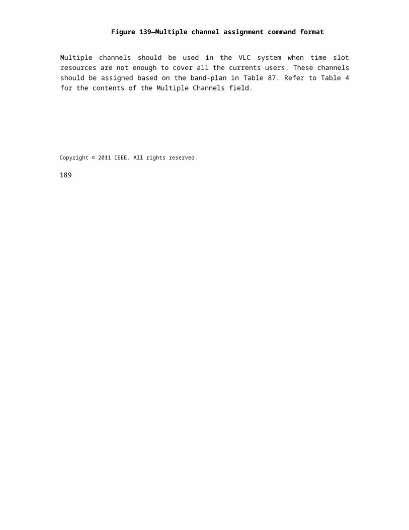
OPTICAL COMMUNICATION IEEE Std 802.15.7r1-20xx
tions can be initialized or released, with or without acknowledgement but always without transporting a pay-load. Moreover, the MSG frame contains information about the bandwidth reservation, by which the devices get informed about the length of the connection queue, requests for bidirectional transmissions and further information to control the transmission of the payload.
The acknowledgement frame (ACK) is used to communicate the relevant ARQ data in the header. It con-tains detailed information for the flow control, requests for bidirectional transmissions, a bad burst indicator, means for channel estimation control, the identifier for the runtime (i.e. time- variant) bit allocation table and a complex field for acknowledgement data depending on whether unicast or multicast is being used. Essen-tially, this field indicates to the transmitter what segment of a frame was lost. Obviously, that list is being used to control the selective repeat mechanism, which is one of the key features in G.hn to reduce the latency and improve the robustness likewise.
The request-to-send (RTS) control frame contains specific means to establish the exchange of data. It con-tains the transmission times of the RTS, CTS and MSG frames, as well as of eventually needed ACK frames and their duration, the device ID of the node that should respond to the request.
The PROBE FTSF is composed of a common part and a variable part. The common part contains fields for the duration of the probe frame and its type, containing either silent signals or channel estimation probe symbols, the number of probe symbols, the used probe guard interval and an additional probe frame type specific field.
The ACK retransmission request (ACKRQ) frame shall allow the receiver to request retransmission of spe-cific receiver windows for either data or management connections or both. Moreover, there are bidirectional variants of the bidirectional MSG (BMSG) and ACK (BACK) frames and an opportunity to add additional frame types by using the frame type extension (FTE) and an opportunity to add an extended header which is similar to the original frame types while adding further functionalities that the original frames can no longer host. This information is sent in further OFDM symbols immediately after the original header.
9.9.4.2 Bits for signaling of optional modulation schemes
The transmitter signals to the receiver the new transmission PHY mode using the eU and STR bits in the advanced modulation PHY header (These three bits need to be accomodated into the High-speed PHY header) . For compliance purposes, the PLCP preamble and the PHY headers are encoded in a DCO-OFDM fashion as described in 3.3 - 3.5.
Following the four BPSK frames containing the PHY header, as well as the NMIMO reference symbols when applicable, the data field is encoded in an eU-OFDM fashion ( The header looks differently in the high-speed PHY) (see Fig. 1(b)). The eU-OFDM algorithm works as follows.
10. PHY service specifications
10.1 Overview
The PHY provides an interface between the MAC sublayer and the physical optical channel. The PHY conceptually includes a management entity called the PLME. This entity provides the layer management service interfaces through which layer management functions may be invoked. The PLME is also responsible for maintaining a database of managed objects pertaining to the PHY. This database is referred to as the PHY PAN information base (PIB).
Copyright © 2011 IEEE. All rights reserved. 385
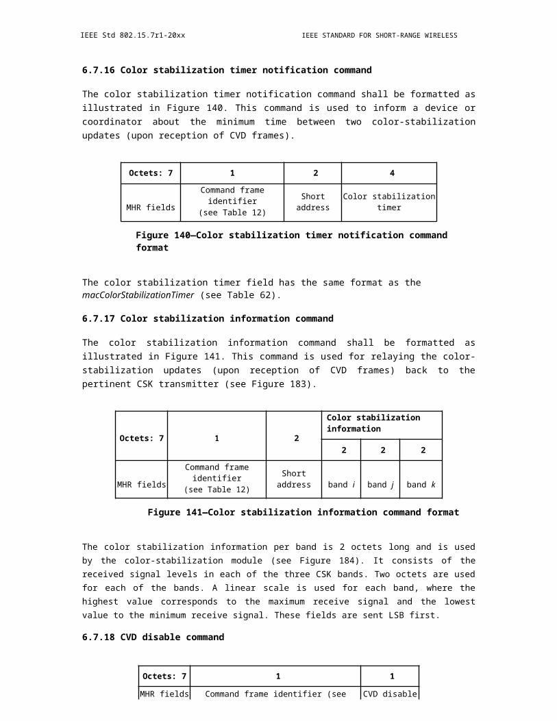
IEEE Std 802.15.7r1-20xx IEEE STANDARD FOR SHORT-RANGE WIRELESS
Figure 231 depicts the components and interfaces of the PHY.
Figure 232—PHY layer service access points
The PHY provides two services, accessed through two SAPs: the PHY data service, accessed through the PHY data SAP (PD-SAP), and the PHY management service, accessed through the PLME’s SAP (PLMESAP). The optical SAP provides an interface between the PHY layer and the optical channel and is not specified in this standard. Any required light source drivers are considered to be part of the optical channel.
10.2 PHY management service
The PLME-SAP allows the transport of management commands between the MLME or the DME and the PLME. Table 109 lists the primitives supported by the PLME-SAP. These primitives are discussed in the subclauses referenced in Table 109.
Table 109—PLME-SAP primitives
PLME-SAP primitive Request Confirm
PLME-CCA 10.2.1 10.2.2
PLME-GET 10.2.3 10.2.4
PLME-SET 10.2.5 10.2.6
PLME-SET-TRX-STATE 10.2.7 10.2.8
PLME-SWITCH 10.2.9 10.2.10
10.2.1 PLME-CCA.request
The PLME-CCA.request primitive requests that the PLME perform a CCA as defined in 9.3.9.
The semantics of the PLME-CCA.request primitive are as follows:
PLME-CCA.request ()
There are no parameters associated with the PLME-CCA.request primitive.
386 Copyright © 20xx IEEE. All rights reserved.
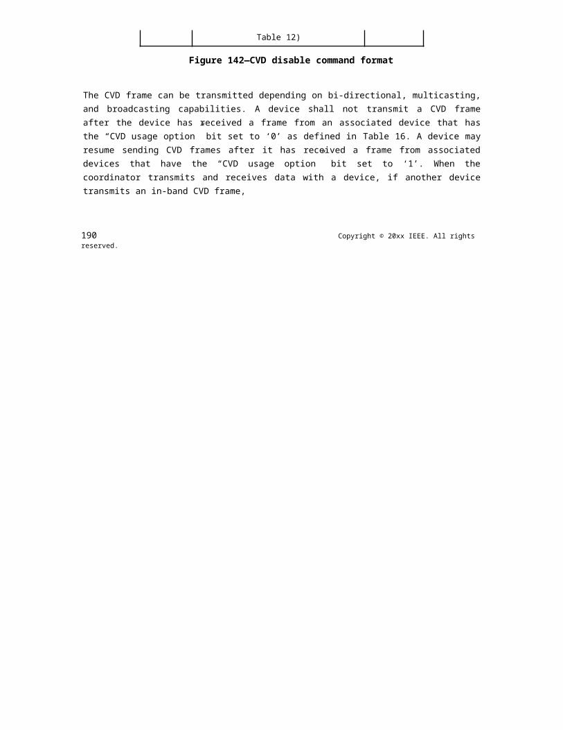
OPTICAL COMMUNICATION IEEE Std 802.15.7r1-20xx
10.2.1.1 When generated
The PLME-CCA.request primitive is generated by the MLME and issued to its PLME whenever the access algorithm requires an assessment of the channel.
10.2.1.2 Effect on receipt
If the receiver is enabled on receipt of the PLME-CCA.request primitive, the PLME will cause the PHY to perform a CCA.
10.2.2 PLME-CCA.confirm
The PLME-CCA.confirm primitive reports the results of a CCA.
The semantics of the PLME-CCA.confirm primitive are as follows:
PLME-CCA.confirm (status)
Table 110 specifies the parameters for the PLME-CCA.confirm primitive.
Table 110—PLME-CCA.confirm parameters
Name Type Valid range Description
TRX_OFF,status Enumeration TX_ON, BUSY, The result of the request to perform a CCA.
IDLE
10.2.2.1 When generated
The PLME-CCA.confirm primitive is generated by the PLME and issued to its MLME in response to a PLME-CCA.request primitive. When the PHY has completed the CCA, the PLME will issue the PLME-CCA.confirm primitive with a status of either BUSY or IDLE, depending on the result of the CCA.
If the PLME- CCA.request primitive is received while the transceiver is disabled (TRX_OFF state) or if the transmitter is enabled (TX_ON state), the PLME will issue the PLME-CCA.confirm primitive with a status of TRX_OFF or TX_ON, respectively.
10.2.2.2 Effect on receipt
On receipt of the PLME-CCA.confirm primitive, the MLME is notified of the results of the CCA. If the CCA attempt was successful, the status parameter is set to either BUSY or IDLE. Otherwise, the status parameter will indicate the error.
10.2.3 PLME-GET.request
The PLME-GET.request primitive requests information about a given PHY PIB attribute.
Copyright © 2011 IEEE. All rights reserved. 387

IEEE Std 802.15.7r1-20xx IEEE STANDARD FOR SHORT-RANGE WIRELESS
The semantics of the PLME-GET.request primitive are as follows:
PLME-GET.request (PIBAttribute)
Table 111 specifies the parameters for the PLME-GET.request primitive.
Table 111—PLME-GET.request parameters
Name Type Valid range Description
PIBAttributeEnumeration As defined in
The identifier of the PHY PIB attribute to get.Table 125
10.2.3.1 Appropriate usage
The PLME-GET.request primitive is generated by the MLME and issued to its PLME to obtain information from the PHY PIB.
10.2.3.2 Effect on receipt
On receipt of the PLME-GET.request primitive, the PLME will attempt to retrieve the requested PHY PIB attribute from its database.
10.2.4 PLME-GET.confirm
The PLME-GET.confirm primitive reports the results of an information request from the PHY PIB.
The semantics of the PLME-GET.confirm primitive are as follows:
PLME-GET.confirm (status,PIBAttribute,PIBAttributeValue)
Table 112 specifies the parameters for the PLME-GET.confirm primitive.
Table 112—PLME-GET.confirm parameters
Name Type Valid range Description
SUCCESS,The result of the request
Status Enumeration for PHY PIB attributeUNSUPPORTED_ATTRIBUTE information.
PIBAttribute Enumeration As defined in Table 125The identifier of the PHY
PIB attribute to get.
PIBAttributeValue Various Attribute specificThe value of the indicatedPHY PIB attribute to get.
388 Copyright © 20xx IEEE. All rights reserved.
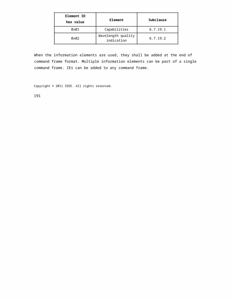
OPTICAL COMMUNICATION IEEE Std 802.15.7r1-20xx
10.2.4.1 When generated
The PLME-GET.confirm primitive is generated by the PLME and issued to its MLME in response to a PLME-GET.request primitive. If the identifier of the PIB attribute is not found in the database, the PLME will issue the PLME-GET.confirm primitive with a status of UNSUPPORTED_ATTRIBUTE.
If the requested PHY PIB attribute is successfully retrieved, the PLME will issue the PLME-GET.confirm primitive with a status of SUCCESS.
10.2.4.2 Effect on receipt
On receipt of the PLME-GET.confirm primitive, the MLME is notified of the results of its request to read a PHY PIB attribute. If the request to read a PHY PIB attribute was successful, the status parameter is set to SUCCESS. Otherwise, the status parameter will indicate the error.
10.2.5 PLME-SET.request
The PLME-SET.request primitive attempts to set the indicated PHY PIB attribute to the given value.
The semantics of the PLME-SET.request primitive are as follows:
PLME-SET.request (PIBAttribute,PIBAttributeValue)
Table 113 specifies the parameters for the PLME-SET.request primitive.
Table 113—PLME-SET.request parameters
Name Type Valid range Description
PIBAttribute EnumerationAs defined in
The identifier of the PIB attribute to set.Table 125
Attribute spe-PIBAttributeValue Various cific, as defined The value of the indicated PIB attribute to set.
in Table 125
10.2.5.1 When generated
The PLME-SET.request primitive is generated by the MLME and issued to its PLME to write the indicated PHY PIB attribute.
10.2.5.2 Effect on receipt
On receipt of the PLME-SET.request primitive, the PLME will attempt to write the given value to the indicated PHY PIB attribute in its database.
10.2.6 PLME-SET.confirm
The PLME-SET.confirm primitive reports the results of the attempt to set a PIB attribute.
Copyright © 2011 IEEE. All rights reserved. 389
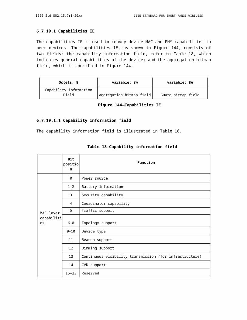
IEEE Std 802.15.7r1-20xx IEEE STANDARD FOR SHORT-RANGE WIRELESS
The semantics of the PLME-SET.confirm primitive are as follows:
PLME-SET.confirm (status,PIBAttribute)
Table 114 specifies the parameters for the PLME-SET.confirm primitive.
Table 114—PLME-SET.confirm parameters
Name Type Valid range Description
SUCCESS,The status of the attempt to setstatus Enumeration UNSUPPORTED_ATTRIBUTE,
the requested PIB attribute.INVALID_PARAMETER
PIBAttribute Enumeration As defined in Table 125The identifier of the PIB
attribute being confirmed.
10.2.6.1 When generated
The PLME-SET.confirm primitive is generated by the PLME and issued to its MLME in response to a PLME-SET.request primitive.
If the PIBAttribute parameter specifies an attribute that is not found in the database, as shown in Table 125, the PLME will issue the PLME- SET.confirm primitive with a status of UNSUPPORTED_ATTRIBUTE. If the PIBAttibuteValue parameter specifies a value that is out of the valid range for the given attribute, the PLME will issue the PLME-SET.confirm primitive with a status of INVALID_PARAMETER.
If the requested PHY PIB attribute is successfully written, the PLME will issue the PLME-SET.confirm primitive with a status of SUCCESS.
10.2.6.2 Effect on receipt
On receipt of the PLME-SET.confirm primitive, the MLME is notified of the result of its request to set the value of a PHY PIB attribute. If the requested value was written to the indicated PHY PIB attribute, the status parameter is set to SUCCESS. Otherwise, the status parameter will indicate the error.
10.2.7 PLME-SET-TRX-STATE.request
The PLME -SET-TRX-STATE.request primitive requests that the PHY entity change the internal operating state of the transceiver. The transceiver will have three main states as follows:
a) Transceiver disabled (TRX_OFF)b) Transmitter enabled (TX_ON)c) Receiver enabled (RX_ON)
390 Copyright © 20xx IEEE. All rights reserved.

OPTICAL COMMUNICATION IEEE Std 802.15.7r1-20xx
The semantics of the PLME-SET-TRX-STATE.request primitive are as follows:
PLME-SET-TRX-STATE.request ( state
)
Table 115 specifies the parameters for the PLME-SET-TRX-STATE.request primitive.
Table 115—PLME-SET-TRX-STATE.request parameters
Name Type Valid range Description
RX_ON, TRX_OFF,The new state in which to configure thestate Enumeration FORCE_TRX_OFF,
transceiver.TX_ON
10.2.7.1 When generated
The PLME -SET-TRX- STATE.request primitive is generated by the MLME and issued to its PLME when the current operational state of the receiver needs to be changed.
10.2.7.2 Effect on receipt
On receipt of the PLME-SET-TRX-STATE.request primitive, the PLME will cause the PHY to attempt to change to the requested state.
10.2.8 PLME-SET-TRX-STATE.confirm
The PLME-SET- TRX-STATE.confirm primitive reports the result of a request to change the internal operating state of the transceiver.
The semantics of the PLME-SET-TRX-STATE.confirm primitive are as follows:
PLME-SET-TRX-STATE.confirm ( status
)
Table 116 specifies the parameters for the PLME-SET-TRX-STATE.confirm primitive.
Table 116—PLME-SET-TRX-STATE.confirm parameters
Name Type Valid range Description
SUCCESS, RX_ON,The result of the request to change the statestatus Enumeration TRX_OFF, TX_ON,
of the transceiver.BUSY_RX, BUSY_TX
Copyright © 2011 IEEE. All rights reserved. 391
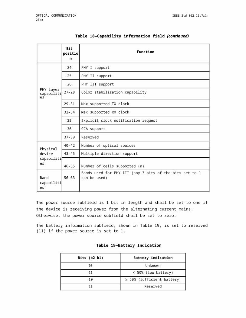
IEEE Std 802.15.7r1-20xx IEEE STANDARD FOR SHORT-RANGE WIRELESS
10.2.8.1 When generated
The PLME-SET-TRX-STATE.confirm primitive is generated by the PLME and issued to its MLME after attempting to change the internal operating state of the transceiver.
10.2.8.2 Effect on receipt
On receipt of the PLME-SET-TRX-STATE.confirm primitive, the MLME is notified of the result of its request to change the internal operating state of the transceiver.
If the state change is accepted, the PHY will issue the PLME-SET-TRX-STATE.confirm primitive with a status of SUCCESS. If this primitive requests a state that the transceiver is already configured, the PHY will issue the PLME-SET-TRX-STATE.confirm primitive with a status indicating the current state, i.e., RX_ON, TRX_OFF, or TX_ON. If this primitive is issued with RX_ON or TRX_OFF argument and the PHY is busy transmitting a PPDU, the PHY will issue the PLME-SET-TRXSTATE.confirm primitive with a status BUSY_TX and defer the state change until the end of transmission. If this primitive is issued with TX_ON or TRX_OFF argument and the PHY is in RX_ON state and has already received a valid preamble, the PHY will issue the PLME-SET-TRX -STATE.confirm primitive with a status BUSY_RX and defer the state change until the end of reception of the PPDU. If this primitive is issued with FORCE_TRX_OFF, the PHY will cause the PHY to go the TRX_OFF state irrespective of the state the PHY is in.
10.2.9 PLME-SWITCH.request
The PLME-SWITCH.request primitive request is used by the DME to request that the PHY entity select the switch to enable the appropriate cells in the SW-BIT-MAP. The semantics of the PLME-SWITCH.request primitive are as follows:
PLME-SWITCH.request ( SW-BIT-MAP,
DIR)
Table 117 specifies the parameters for the PLME-SET-TRX-STATE.request primitive.
Table 117—PLME-SWITCH.request parameters
Name Type Valid range Description
One bit for each optical source or photode-tector and is dependent on the direction.Setting the kth bit to a “1” brings the corre-
SW-BIT-MAPVector of
Booleansponding optical source or photodetector
‘n’ ‘m’entries into the cell group. ‘n’ is the number of cellsand ‘m’ is the number of distinct data
streams from the PHY. The value of ‘m’ isthree for PHY III.
DIR Boolean ‘0’ is for TX and ‘1’ is for ‘RX’
10.2.9.1 When generated
The PLME-SWITCH.request primitive is generated by the DME and issued to its PLME when the current cell selection needs to be changed.
392 Copyright © 20xx IEEE. All rights reserved.
OPTICAL COMMUNICATION IEEE Std 802.15.7r1-20xx
10.2.9.2 Effect on receipt
On receipt of the PLME-SWITCH.request primitive, the PLME will cause the PHY to attempt to change to the cell.
10.2.10 PLME-SWITCH.confirm
The PLME-SWITCH.confirm primitive reports the result of a request to change the currently operating cell.
The semantics of the PLME-SWITCH.confirm primitive are as follows:
PLME-SWITCH.confirm (status)
Table 118 specifies the parameters for the PLME-SWITCH.confirm primitive.
Table 118—PLME-SWITCH.confirm parameters
Name Type Valid range Description
status Enumeration SUCCESS The result of the request to change the cell.
10.2.10.1 When generated
The PLME-SWITCH.confirm primitive is generated by the PLME and issued to its DME after attempting to change the cell.
10.2.10.2 Effect on receipt
On receipt of the PLME-SWITCH.confirm primitive, the DME is notified of the result of its request to change the currently operating cell.
If the PHY switch is able to select the new cell, the PHY will issue the PLME-SWITCH.confirm primitive with a status of SUCCESS.
10.3 PHY data service
The PD-SAP supports the transport of MPDUs between a local MAC sublayer and a local PHY layer entity. Table 119 lists the primitives supported by the PD-SAP.
Table 119—PD-SAP primitives
PD-SAP primitive Request Confirm Indication
PD-DATA 10.3.1 10.3.2 10.3.3
Copyright © 2011 IEEE. All rights reserved. 393
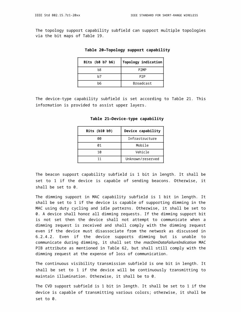
IEEE Std 802.15.7r1-20xx IEEE STANDARD FOR SHORT-RANGE WIRELESS
10.3.1 PD-DATA.request
The PD-DATA.request primitive requests the transfer of data from the MAC sublayer to form a PSDU at the local PHY entity.
The semantics of the PD-DATA.request primitive are as follows:
PD-DATA.request (psduLength,psdu,bandplanID)
Table 120 specifies the parameters for the PD-DATA.request primitive.
Table 120—PD-DATA.request parameters
Name Type Valid range Description
psduLengthUnsigned
0–aMaxPHYFrameSizeThe number of octets in the PSDU to be
Integer transmitted by the PHY entity.
psdu Set of octetsThe set of octets forming the PSDU to
be transmitted by the PHY entity.
bandplanIDUnsigned
0–6 Color band channel of PSDU.Integer
10.3.1.1 When generated
The PD -DATA.request primitive is generated by a local MAC sublayer entity and issued to its PHY entity to request the transmission of an PPDU.
10.3.1.2 Effect on receipt
The receipt of the PD-DATA.request primitive by the PHY entity will cause the transmission of the supplied PPDU.
10.3.2 PD-DATA.confirm
The PD-DATA.confirm primitive confirms the end of the transmission of data from a local MAC sublayer entity.
The semantics of the PD-DATA.confirm primitive are as follows:
PD-DATA.confirm (status)
Table 121 specifies the parameters for the PD-DATA.confirm primitive.
394 Copyright © 20xx IEEE. All rights reserved.
OPTICAL COMMUNICATION IEEE Std 802.15.7r1-20xx
Table 121—PD-DATA.confirm parameters
Name Type Valid range Description
SUCCESS,The result of the request tostatus Enumeration RX_ON, TRX-
transmit a frame._OFF
10.3.2.1 When generated
The PD-DATA.confirm primitive is generated by the PHY entity and issued to its MAC sublayer entity in response to a PD-DATA.request primitive. Provided the transmitter is enabled (TX_ON state), the PHY will first construct a PPDU containing the supplied PSDU, and then transmit the PPDU. When the PHY entity has completed the transmission, it will issue the PD-DATA.confirm primitive with a status of SUCCESS.
If the PD- DATA.request primitive is received while the receiver is enabled (RX_ON state) or if the transceiver is disabled (TRX_OFF state), the PHY entity will issue the PD-DATA.confirm primitive with a status of RX_ON or TRX_OFF, respectively.
10.3.2.2 Effect on receipt
On receipt of the PD-DATA.confirm primitive, the MAC sublayer entity is notified of the result of its request to transmit. If the transmission attempt was successful, the status parameter is set to SUCCESS. Otherwise, the status parameter will indicate the error.
10.3.3 PD-DATA.indication
The PD-DATA.indication primitive indicates the transfer of data from the PHY to the local MAC sublayer entity.
The semantics of the PD-DATA.indication primitive are as follows:
PD-DATA.indication (psduLength,psdu,ppduLinkQuality)
Table 122 specifies the parameters for the PD-DATA.indication primitive.
10.3.3.1 When generated
The PD -DATA.indication primitive is generated by the PHY entity and issued to its MAC sublayer entity to transfer a received PSDU. This primitive will not be generated if the received psduLength field is zero or greater than aMaxPHYFrameSize.
10.3.3.2 Effect on receipt
On receipt of the PD-DATA.indication primitive, the MAC sublayer is notified of the arrival of data across the PHY data service.
Copyright © 2011 IEEE. All rights reserved. 395
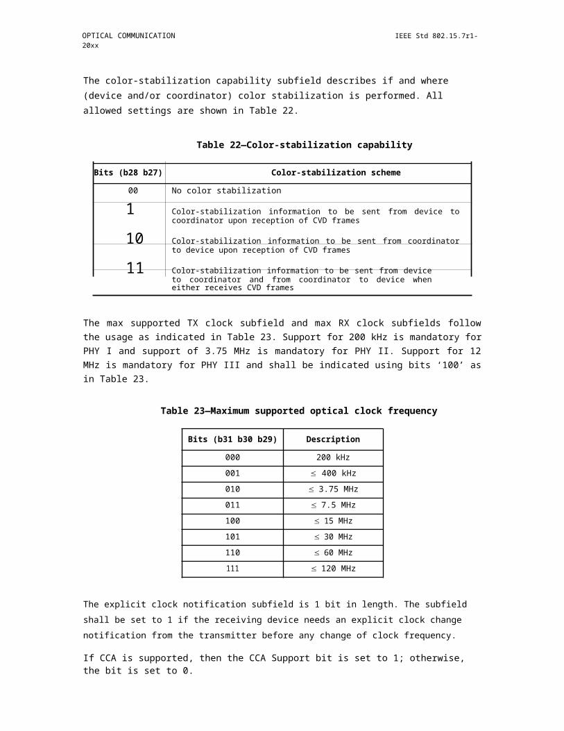
IEEE Std 802.15.7r1-20xx IEEE STANDARD FOR SHORT-RANGE WIRELESS
Table 122—PD-DATA.indication parameters
Name Type Valid Description
UnsignedThe number of octets contained in
psduLength 0–aMaxPHYFrameSize the PSDU received by the PHYInteger entity.
psdu Set of octets —The set of octets forming the
PSDU received by the PHY entity.
Wavelength quality indication
ppduLinkQualityUnsigned
0x00–0xff(WQI) value measured during
Integer reception of the PPDU as definedin 6.7.19.2.
10.4 PHY enumeration description
Table 123 shows a description of the PHY enumeration values defined in the PHY specification.
Table 123—PHY enumeration description
Enumeration Value Description
BUSY 0x00 The CCA attempt has detected a busy channel.
BUSY_RX 0x01 The transceiver is asked to change its state while receiving.
BUSY_TX 0x02The transceiver is asked to change its state while
transmitting.
FORCE_TRX_OFF 0x03 The transceiver is to be switched off.
IDLE 0x04 The CCA attempt has detected an idle channel.
INVALID_PARAMETER 0x05A SET/GET request was issued with a parameter in the
primitive that is out of the valid range.
RX_ON 0x06The transceiver is in, or is to be configured into, the receiver
enabled state.
SUCCESS 0x07 The request completed successfully.
TRX_OFF 0x08The transceiver is in, or is to be configured into, the
transceiver disabled state.
TX_ON 0x09The transceiver is in, or is to be configured into, the
transmitter enabled state.
UNSUPPORTED_ATTRIBUTE 0x0aA SET/GET request was issued with the identifier of an
attribute that is not supported.
10.5 PHY constants and PIB attributes
This subclause specifies the constants and attributes required by the PHY.
396 Copyright © 20xx IEEE. All rights reserved.
OPTICAL COMMUNICATION IEEE Std 802.15.7r1-20xx
10.5.1 PHY constants
The constants that define the characteristics of the PHY are presented in Table 124. These constants are hardware dependent and shall not be changed during operation.
Table 124—PHY constants
Constant Description Value
aMaxPHYFrameSizeThe maximum PSDU size (in octets) the PHY 1023 for PHY I, 65535
shall be able to receive. for PHY II, III
aTurnaroundTime-TX-RXTX-to-RX maximum turnaround time (as defined
zero optical clock cyclesin 9.3.5)
PHY I: ≤ 240 optical
aTurnaroundTime-RX-TXRX-to-TX maximum turnaround time (as defined clock cycles,
in 9.3.6) PHY II, III: ≤ 5120 opti-cal clock cycles
aPreambleFrequency The preamble field frequency, this should be uni-
versal across different hardware that comply this 2.2 KHz(aPF) definition.
aFrequencyLabelingRatio This indicates the frequency ratio of the frequency1.5(aFLR) labeling field (aPF×aFLR).
All the PHY PIB are labeled as frequency ratio, using aPreambleFrequency as the baseline. If one would like to extend the PIB attribute table, do not overlap the ratio with aFrequencyLabelingRatio, since it will seriously interfere the interpretation of all subsequent data symbols.
10.5.2 PHY PIB attributes
The PHY PIB comprises the attributes required to manage the PHY of a device. Each of these attributes can be read or written using the PLME-GET.request and PLME-SET.request primitives, respectively. The attributes contained in the PHY PIB are presented in Table 125.
The phyOccApplicationSpecificMode is used to specify the PHY mode for a given geolocation such as the APP associated with a particular store, The information is provided by an out-of-band channel (i.e. WiFi) and is provided by the particular store prior usage (i.e. by downloading the stores OCC APP).
Table 125—PHY PIB attributes
Attribute Identifier Type Range Description
The wavelength used for all
phyCurrentChannel 0x00 Integer 0–6following transmissions and
receptions (as defined in9.3.1).
b0=CCA mode 1b1=CCA mode 2
phyCCAMode 0x01 Octet enumeratedb2=CCA mode 3b3–b7=reserved
The CCA modes are definedin 9.3.9.
Copyright © 2011 IEEE. All rights reserved. 397
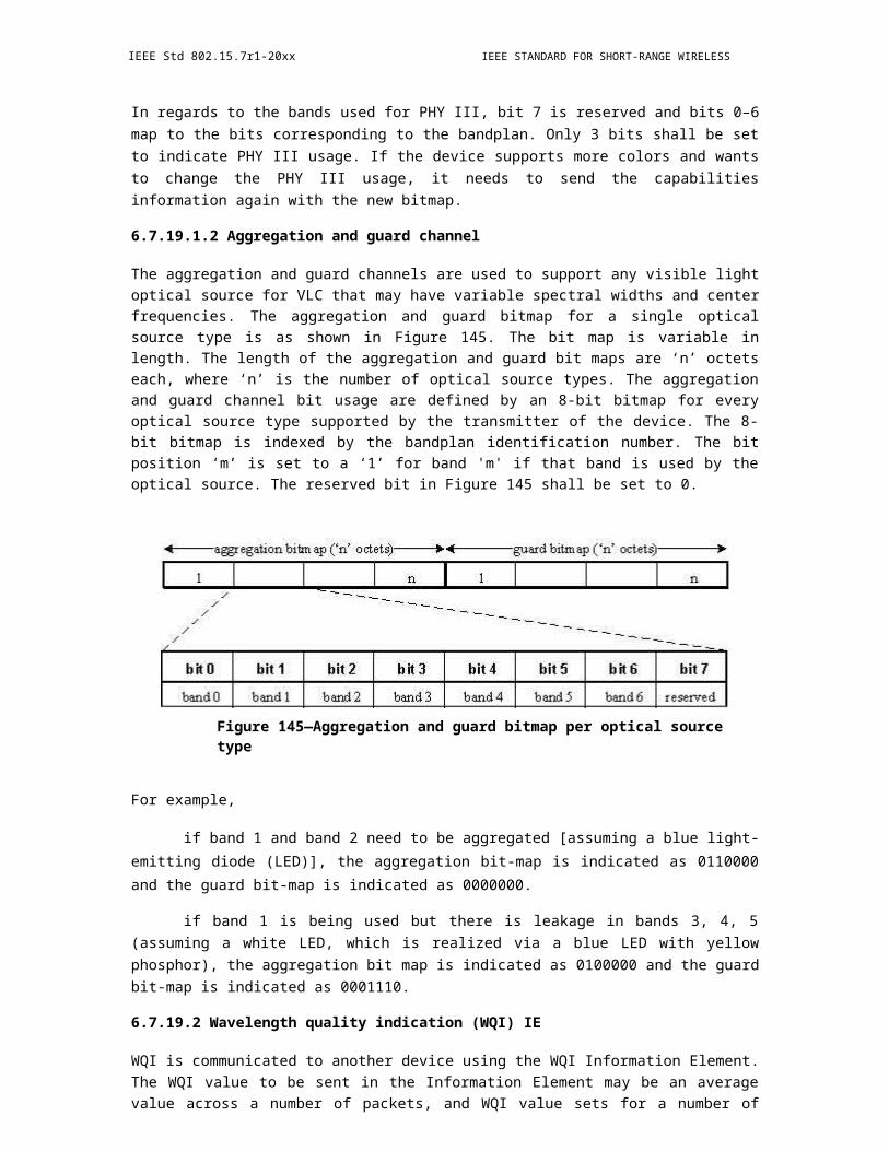
IEEE Std 802.15.7r1-20xx IEEE STANDARD FOR SHORT-RANGE WIRELESS
Table 125—PHY PIB attributes (continued)
Attribute Identifier Type Range Description
0 is 0% or no visibility andphyDim 0x02 Integer 0–1000 1000 is 100% visibility (full
brightness).
Indicates the PSDU carriesthe frequencies that will beused for the data frame later
on.
phyFrequencyLabeling* Frequency * This PIB attribute is explic-ration = 1.5 itly defined for future extensi-
bility. For now, onlyaFrequencyLabelingRatio cancontrol the frequency ratio ofthe Frequency Labeling field.
Indicates the the PSDU car-
phyUseSplitterSymbolFrequency ries the flag to toggle whetherratio = 0.83 the device is going to use SSs
or not.
Indicates the PSDU carries
Frequency the splitter frequency. If thephySplitterFrequency SS is already in used, it will
ratio = 0.71 use the original phySplitter-Frequency until next cycle.
Indicates the PSDU carries
Frequency the duration of the SS. This isphySplitterDuration represented as a ratio of sym-
ratio = 0.62 bol duration to splitter dura-tion in integer.
Indicates the PSDU carriesthe duration of a data symbolin the PSDU. This is repre-
sented as a ratio of the symbolduration to 1/30 second in thebase 2 log scale. For example,
Frequency if the symbol duration is 1/phySymbolDuration 120 second, then the PSDU
ratio = 0.55 would contain an integer -2. Ifthe symbol duration is 1/15
second, then the PSDU wouldcontain an integer 2. Note thatthis does not affect the dura-tion of the preamble field and
the optional field.
This attribute is set to a one toindicate that an extended pre-
phyUseExtendedMode 0x03 Integer 0–1 amble or visibility pattern isto be used. Otherwise, it is set
to zero.
The row index A table with three columns256 by 3 ranges from 0 per row. The first row is the
phyColorFunction 0x04 matrix of to 255 and the index, the second and theinteger elements range third columns define the
from 0 to 255. color.
398 Copyright © 20xx IEEE. All rights reserved.
OPTICAL COMMUNICATION IEEE Std 802.15.7r1-20xx
Table 125—PHY PIB attributes (continued)
Attribute Identifier Type Range Description
The frequency of blinkingnotification:0: 0.25 Hz1: 0.5 Hz2: 0.75 Hz
phyBlinkingNotification- 3: 1 Hz
0x05 Integer 0–10 4: 1.25 HzFrequency 5: 1.5 Hz
6: 1.75 Hz7: 2 Hz8: 2.25 Hz9: 2.5 Hz10: 2.75 Hz
phyOccApplicationSpe- This attribute specifies the
0x06 Integer 0-N application specific PHYcificMode mode as shown in Table 126.
phyOccProposerID 3 bit Integer 0-8
This attribute specifies theapplication specific PHYmode.
phyINVApplicationSpe- 0 : Normal Data (Media Con-
0x10 Unsigned 0~255 tent, Information ContentcifiMode based on the Application used
for)1 : ID Data2 : Authentication Data
Table 126—OCC Application Specific PHY Mode
PIB Attribute Value Mode Name Mode
0 Rolling Shutter Sampling #1 First Rolling Shutter Mode
1 Rolling Shutter Sampling #2 Second Rolling Shutter Mode
: : :
i UFSOOK #1 First UFSOOK Mode
i+1 UFSOOK #2 Second UFSOOK Mode
: : :
j LED ID Mode #1 First LED ID Mode
j+1 LED ID Mode #2 Second LED ID Mode
: : :
Copyright © 2011 IEEE. All rights reserved. 399
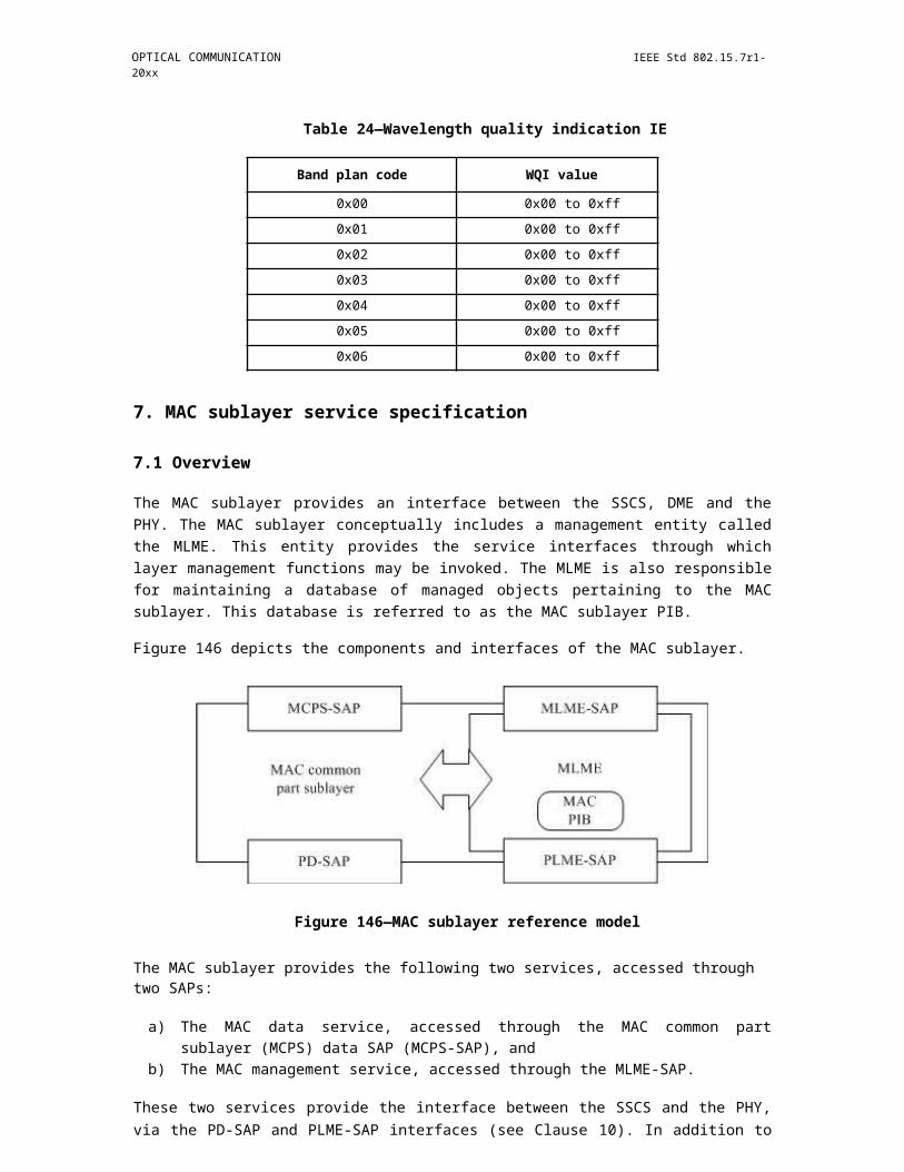
IEEE Std 802.15.7r1-20xx IEEE STANDARD FOR SHORT-RANGE WIRELESS
Table 126—OCC Application Specific PHY Mode
PIB Attribute Value Mode Name Mode
k RS-FSK Mode #1 First RS-FSK Mode
k+1 RS-FSK Mode #2 Second RS-FSK Mode
: : :
N 2-D Sequential Spatial Code 2-D Sequential Spatial Code
Table 127—Kookmin OCC application specification PHY specific mode
PIB AttributeMode name ModeValue
0 Kookmin RS-OOK Mode 1 Manchester coding oversampling & short frame mode
1 Kookmin RS-OOK Mode 2 4B6B coding oversampling & long frame mode
2 Kookmin RS-OOK Mode 3 Manchester coding error detection & long frame mode
3 Kookmin RS-OOK Mode 4 4B6B coding error detection & long frame mode
4 Kookmin RS-FSK Mode 1 M-FSK 32-frequency
5 Kookmin RS-FSK Mode 2 M-FSK 32-frequency & 2-phase + FEC mode
6 Kookmin RS-FSK Mode 3 M-FSK 64-frequency & 2-phase + FEC mode
11. PHY I specifications
PHY I is targeted towards applications requiring low data rates as shown in Table 76. For PHY I, the PHY header shall be sent at 11.67 kb/s if the 200 kHz optical clock rate is selected or at 35.56 kb/s if the 400 kHz optical clock rate is selected. Support for 11.67 kb/s at 200 kHz optical clock is mandatory.
11.1 Reference modulator diagram
A reference implementation of the modulator is shown in Figure 232.
400 Copyright © 20xx IEEE. All rights reserved.

OPTICAL COMMUNICATION IEEE Std 802.15.7r1-20xx
Figure 233—Reference modulator diagram for PHY I
For PHY I, concatenated coding is used with a combination of convolutional outer code and a RS inner code. The RS encoder output is padded with zeros to form an interleaver boundary. The padded zeros are then punctured (discarded) and the result is sent to the inner convolutional encoder. The PHR and PSDU parts of the frame are subject to the FEC for error protection. The PHR is encoded using parameters corresponding to the lowest data rate for the currently negotiated clock rate.
11.2 Outer forward error correction encoder
Systematic RS codes are used for the PHY I outer FEC with GF(16), generated by the polynomial x4+x+1. The generators for the RS(n, k) codes for PHY I (see Table 76) are given in Table 128, where is a primitive element in GF(16).
Table 128—Generator polynomials
(n,k) g(x)
(15,11) x4+α13x3+α6x2+α3x+α10
(15,7) x8+α14x7+α2x6+α4x5+α2x4+α13x3+α5x2+α11x1+α6
(15,4) x11+α9x10+α8x9+α4x8+α9x7+α13x6+α4x5+α12x4+α4x3+α5x2+α3x+α6
(15,2) x13+α3x12+α8x11+α9x10+α2x9+α4x8+α14x7+α6x6+α10x5+ α7x4+ α13x3+ α11x2+ α5x+α
The Reed-Solomon code may be shortened for the last block if it does not meet the block size requirements. No zero padding is required for the RS code. A shortened RS code is used for frame sizes not matching code word boundaries via the following operation to minimize padding overhead.
Starting with a RS(n,k) code, one can get an RS(n-s, k-s) shortened code as follows:
a) Pad the k-s RS symbols with s zero RS symbols.b) Encode using RS(n, k) encoder.c) Delete the padded zeros (do not transmit them).d) At the decoder, add the zeros, then decode.
11.3 Interleaving and puncturing block
A block interleaver is used as an interleaver between the inner convolutional code and the outer RS code as shown in Figure 233. The interleaver is of a fixed height n but has a flexible depth D, dependent on the
Copyright © 2011 IEEE. All rights reserved. 401
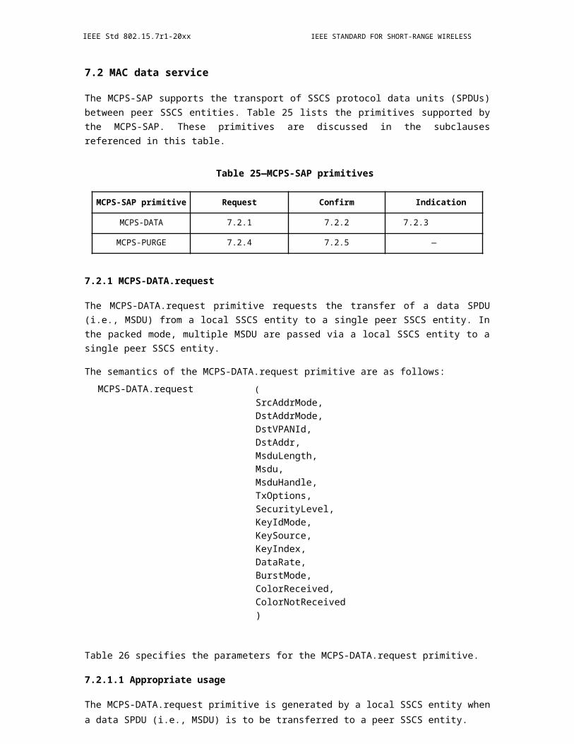
IEEE Std 802.15.7r1-20xx IEEE STANDARD FOR SHORT-RANGE WIRELESS
frame size. The flexible depth of the interleaver and the puncturing block after the interleaver is used to minimize padding overhead.
Figure 234—Interleaver for PHY I
The following parameters are used to describe the interleaver:
n: RS codeword lengthk: Number of information data symbols in a RS codeword q: Number of elements in the Galois field: GF(q)Lframe: Input frame size in bytesSframe: Number of symbols at the input of the RS encoderS: Number of symbols from the output of the shortened RS encoder Sblock: The size of the interleaver usedD:The interleaving depth
i: Ordered indices take the values 0, 1, …, Sblock–1 l(i): Interleaved indicesp: Number of zero RS symbolst: Ordered indices take the values 0, 1, …, pz(t): Locations of the bits to be punctured at the output of the interleaver before transmission
The interleaver and the locations to be punctured are described by the equations shown in Equation (3).
402 Copyright © 20xx IEEE. All rights reserved.

OPTICAL COMMUNICATION
S frame
L frame *8
log2 (q) S frame
S = n * - k - S frame mod k k
D S n
Sblock n*D
p n- (S mod n) i
l(i) = (i mod D) * n + ; for i 0,1, .., (Sblock 1) D
z(t) = (n p 1)*D t*D 1; for

IEEE Std 802.15.7r1-20xx
(3)
The length of the frame is communicated to the receiver in the header so that the receiver can adaptively adjust the interleaver based on the frame sizes. When the data rates corresponding to transmissions using the concatenated codes are used, the header shall also be interleaved according to procedure shown in Equation (3). Since the length of the header is fixed, the receiver can deinterleave the header without explicit transmission of the header length.
11.4 Inner forward error correction encoder
The inner code is a based on a rate-1/3 mother convolutional code of constraint length seven (K=7) with generator polynomial g0 = 1338; g1 = 1718; g2 = 1658, as shown in Figure 234.
PHR,
PSDU X0
g0+
t t t t t t
A0encoded+
B0 symbolsg1 C0
+
t t t t t t
g2
Figure 235—Rate-1/3 mother convolutional code with constraint length 7
Six tail bits of zeros shall be added at the end of the encoding in order to terminate the convolutional encoder to an all zeros state. The tail bit of zeros shall be applied to both the header and the payload when the inner convolutional code is used.
Copyright © 2011 IEEE. All rights reserved. 403
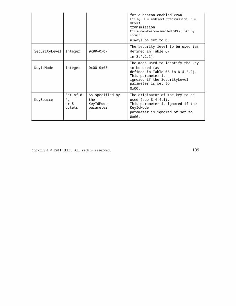
IEEE Std 802.15.7r1-20xx IEEE STANDARD FOR SHORT-RANGE WIRELESS
11.4.1 Rate-1/4 code
The rate-1/4 code is obtained by puncturing the rate-1/3 mother code to a rate-1/2 code, as shown in Figure 235, and then using a simple repetition code as shown in Figure 236.
Source Bits X0 X1
A0 A1
Punctured bitEncoded Bits B0 B1
C0 C1
Transmitted Bits A0 B0 A1 B1
Figure 236—Puncturing pattern to obtain rate-1/2 code
A0 B0 A1 B1
A0 A0 B0 B0 A1 A1 B1 B1
Figure 237—Repetition pattern used to obtain the effective rate-1/4 code
11.4.2 Rate-1/3 code
The rate-1/3 code is obtained by using the outputs of the rate-1/3 mother code shown in Figure 234.
11.4.3 Rate-2/3 code
The rate-2/3 code is obtained by puncturing the rate-1/3 mother code, as shown in Figure 237.
Source Bits X0 X1
A0 A1Punctured bitEncoded BIts B0 B1
C0 C1
Transmitted Bits A0 B0 B1
Figure 238—Puncturing pattern to obtain rate-2/3 code
404 Copyright © 20xx IEEE. All rights reserved.

OPTICAL COMMUNICATION IEEE Std 802.15.7r1-20xx
11.5 Run-length limiting encoder
11.5.1 4B6B encoding for VPPM modes
All VPPM PHY I modes shall use 4B6B encoding. The 4B6B expands 4-bit to 6-bit encoded symbols with DC balance. The counts of 1 and 0 in every VPPM encoded symbol is always equal to 3. Table 129 defines the 4B6B code.
Table 129—Mapping input 4B to output 6B
4B (input) 6B (output) Hex
0000 001110 0
0001 001101 1
0010 010011 2
0011 010110 3
0100 010101 4
0101 100011 5
0110 100110 6
0111 100101 7
1000 011001 8
1001 011010 9
1010 011100 A
1011 110001 B
1100 110010 C
1101 101001 D
1110 101010 E
1111 101100 F
The features of the 4B6B code are as follows:
a) Always 50% duty cycle during one encoded symbolb) DC balanced run length limiting codec) Error detection capabilityd) Run length is limited to foure) Allows reasonable clock recovery
Copyright © 2011 IEEE. All rights reserved. 405

IEEE Std 802.15.7r1-20xx IEEE STANDARD FOR SHORT-RANGE WIRELESS
Figure 1—Unipolar OFDM signal generation (one stream)
Figure 239—Illustrative comparison between non-encoded and 4B6B encoded symbols
11.5.2 Manchester encoding for OOK mode
All OOK PHY I modes shall use Manchester DC balancing encoding. The Manchester code expands each bit into an encoded 2-bit symbol as shown in Table 130.
Table 130—Manchester encoding
bit Manchester symbol
0 01
1 10
11.6 Data mapping for VPPM
The data mapping for VPPM shall be defined as in Table 131. The physical value mapped from the logical data ‘0’ has a transition from ‘high’ to ‘low’, and the physical value mapped from the logical data ‘1’ has a transition from ‘low’ to ‘high’, as shown in Table 131. ‘Low’ and ‘high’ values are defined in 9.3.2. The variable d in Table 131 is the VPPM duty cycle, and it is assigned by the VPPM-mode dimming mechanism described in 9.5.2.3. It can be varied in steps of 0.1.
Table 131—Definition of data mapping for VPPM mode
Logical valuePhysical value
d is the VPPM duty cycle (0.1 d 0.9)
0High 0 t < dT
Low dT t < T
1Low 0 t < (1 – d)T
High (1 – d)Tt < T
406 Copyright © 20xx IEEE. All rights reserved.
OPTICAL COMMUNICATION IEEE Std 802.15.7r1-20xx
12. PHY II specifications
PHY II is targeted towards applications requiring high data rates, as shown in Table 77. For PHY II, the PHY header shall be sent at one of the following data rates: 1.25 Mb/s, 2.5 Mb/s, 6 Mb/s, 12 Mb/s, 24 Mb/s, or 48 Mb/s, depending on the selected optical clock rate. Support for 1.25 Mb/s at an optical clock of 3.75 MHz is mandatory.
12.1 Reference modulator diagram
A reference implementation is in Figure 239. The PHR and PSDU parts of the frame are subject to the FEC for error protection. The PHR is encoded using parameters corresponding to the lowest data rate for the currently negotiated clock rate.
Figure 240—Reference modulator diagram for PHY II
12.2 Forward error correction encoder
A systematic Reed-Solomon code operating on GF(256) shall be used for PHY II to correct errors and increase the system reliability. The Reed-Solomon code may be shortened for the last block if it does not meet the block size requirements, as specified for PHY I in 11.2. No zero padding is required for the RS code.
The Reed-Solomon code is defined over GF(256) with a primitive polynomial x8+x4+x3+x2+1. The generator for the RS(160, 128) code and the RS(64, 32) code is given by
g(x) =x32+α11x31+α8x30+α109x29+α194x28+α254x27+α173x26+α11x25+α75x24+α218x23+α148x23+α149
x21+α44x20+α0x19+α137x18+α104x17+α43x16+α137x15+α203x14+α99x13+α176x12+a59x11+α91x1
0+α194x9+α84x8+α53x7+α248x6+α107x5+α80x4+α28x3+α215x2+α251x+α18 (4)where α is a primitive element in GF(256).
For the VPPM modes using 4B6B encoding, the RS code word (d1,..., d8) from the GF(256) RS code is broken into 2 nibbles (d1,.., d4) and (d5,.., d8). These nibbles are sent LSB first to the 4B6B encoder as shown in Figure 240.
Copyright © 2011 IEEE. All rights reserved. 407

IEEE Std 802.15.7r1-20xx IEEE STANDARD FOR SHORT-RANGE WIRELESS
Figure 241—GF(256) RS encoder usage with 4B6B encoder
12.3 Run-length limiting encoder
All PHY II VPPM modes shall use 4B6B encoding as defined in 11.5.1. All OOK PHY II modes shall use 8B10B encoding as specified in ANSI/INCITS 373.
12.4 Data mapping for VPPM
All PHY II VPPM modes shall use data mapping as defined in 11.6.
13. PHY III specifications
The data rates supported by PHY III are shown in Table 78. For PHY III, the PHY header shall be sent at 12 Mb/s if the 12 MHz optical clock rate is selected or at 24 Mb/s if the 24 MHz optical clock rate is selected. Support for 12 Mb/s at 12 MHz is mandatory. PHY III devices shall utilize PHY II devices for device discovery. After all devices in the network are discovered and if all of them support PHY III, the coordinator can decide to switch to PHY III mode of operation. In addition, PHY III devices shall exchange their supported bands for CSK operation with the coordinator and the coordinator shall verify that the frequency bands supported in all PHY III devices in the network support reliable CSK communication. This is to ensure that transmission on two optical frequency bands of the transmitting device does not fall within one optical filter band of the receiving device for CSK operation, leading to communication errors during CSK operation.
13.1 Reference modulator diagram
Figure 241 shows the CSK system configuration for PHY III with light sources of three colors (bands i, j, and k). After scrambling and channel coding, data is transformed into xy values, according to the mapping rule on the xy color coordinates by the color coding block. The PHR and PSDU parts of the frame are subject to the FEC block for error protection. The PHR is encoded using parameters corresponding to the lowest data rate for the currently negotiated clock rate. The channel estimation sequence is transmitted after the PHR as shown in Figure 189b.
408 Copyright © 20xx IEEE. All rights reserved.
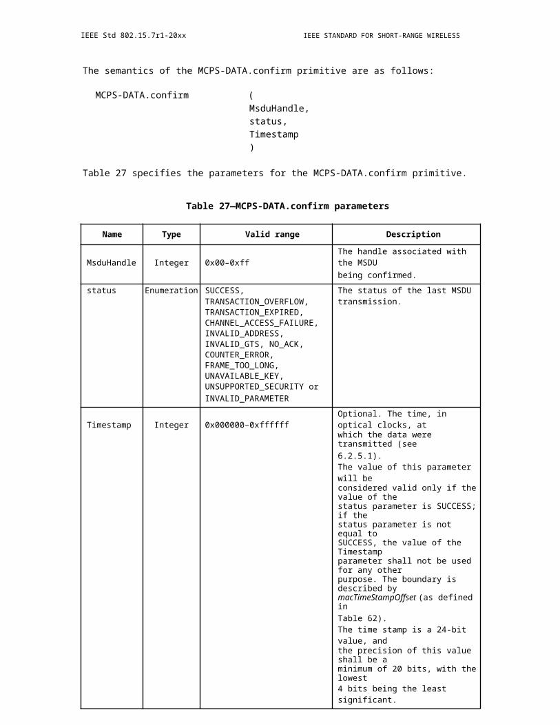
OPTICAL COMMUNICATION IEEE Std 802.15.7r1-20xx
xPi
xychannel color Pj
data scramblery
toencoder coding
Pi,Pj,PkPk
channelestimationsequence
Figure 242—CSK system diagram for PHYIII
optical source
D/A bandi
D/A bandj
D/A bandk
13.2 Scrambler
A scrambler shall be used to ensure pseudo- random data for the PHY III. The scrambler shall be applied to the entire PSDU. In addition, the scrambler shall be initialized to a seed value dependent on the topology dependent pattern at the beginning of the PSDU. The polynomial generator, g(D ), for the pseudo-random binary sequence (PRBS) generator shall be: g(D) = 1 + D 14 + D15, where D is a single bit delay element. Using this generator polynomial, the corresponding PRBS, x[n], is generated as in Equation (5).
x[n] = x[n − 14] x[n − 15], n = 0, 1, 2, … (5)
where “ ” denotes modulo-2 addition. The following sequence defines the initialization vector, xinit,
which is specified by the parameter “seed value” in Table 132:
xinit = [xi[−1] xi[-2] … xi[−14]xi[−15]], …
where xi[−k] represents the binary initial value at the output of the kth delay element. The scrambled data
bits, vm, are defined in Figure 242 and shall be calculated as:
v[m] = s[m] x[m], m = 0, 1, 2, …
where s[m] represents the non-scrambled data bits. The side-stream de-scrambler at the receiver shall be initialized with the same initialization vector, xinit, used in the transmitter scrambler. The initializationvector is determined from the TDP.
The 15-bit initialization vector or seed value shall correspond to the seed identifier as defined in Table 132, corresponding to the TDP pattern. The seed values shall be incremented in a roll-over fashion for each frame sent by the PHY. For example, if the seed value used is the seed corresponding to P3 in the first frame, the seed value corresponding to P4 is used in the second frame, seed value corresponding to P1 is used in the third frame and so on. All consecutive frames, including retransmissions, shall be sent with a different initialseed value.
Copyright © 2011 IEEE. All rights reserved. 409

IEEE Std 802.15.7r1-20xx IEEE STANDARD FOR SHORT-RANGE WIRELESS
Table 132—Scrambler seed selection
TDP Seed Value PRBS Outputxinit = xi[-1] xi[-2]… xi[-15] First 16 bits
x[0] x[1] … x[15]
P1 0011 1111 1111 111 0000 0000 0000 1000
P2 0111 1111 1111 111 0000 0000 0000 0100
P3 1011 1111 1111 111 0000 0000 0000 1110
P4 1111 1111 1111 111 0000 0000 0000 0010
unscrambled scrambleddata datas[n] v[n]
x[n] D x[n-1] D x[n-2] x[n-13] D x[n-14] D x[n-15]
Figure 243—Scrambler block diagram
13.3 Channel encoder
When used, the channel encoding for PHY III is obtained using the ½ RS(64, 32) code as defined in 12.2.
13.4 CSK constellation overview
The CSK signal is generated by using three color light sources out of the seven color bands that are defined in 9.3.1. The three vertices of the CSK constellation triangle are decided by the center wave length of the three color bands on xy color coordinates. It is possible that some of the optical sources would have a spectral peak at a different frequency than the center of the bandplan. It is also possible that the spectrum of the optical source would be distributed among over multiple frequency bands. Implementers of CSK systems can select the color band based on the center wave length of the actual optical source. Table 133 shows the xy color coordinates values assuming the optical source is chosen with the spectral peak occurring at the center of each of the seven color bands. The color calibration function in 13.9 can compensate color coordinate errors caused by the drifting of the optical source characteristics and cancel any interference between the three colors.
Figure 243 shows the center of color bands of Table 133 on xy color coordinates.
410 Copyright © 20xx IEEE. All rights reserved.

OPTICAL COMMUNICATION IEEE Std 802.15.7r1-20xx
Table 133—xy color coordinates
Band (nm) Code Center (nm) (x, y)
380–478 000 429 (0.169, 0.007)
478–540 001 509 (0.011, 0.733)
540–588 010 564 (0.402, 0.597)
588–633 011 611 (0.669, 0.331)
633–679 100 656 (0.729, 0.271)
679–726 101 703 (0.734, 0.265)
726–780 110 753 (0.734, 0.265)
y
001
010
011100 101 110
000x
Figure 244—Center of color bands on xy color coordinates
13.5 CSK constellation design rules
13.5.1 Design rule for 4-CSK
4-CSK symbol points are defined by the design rule in Figure 244. Points I, J, and K show the center of the three color bands on xy color coordinates in Table 133. In Figure 244, x-axis and y-axis are the relative value. S0 to S3 are four symbol points of 4-CSK. S1, S2, and S3 are three vertices of the triangle IJK. S0 is
Copyright © 2011 IEEE. All rights reserved. 411
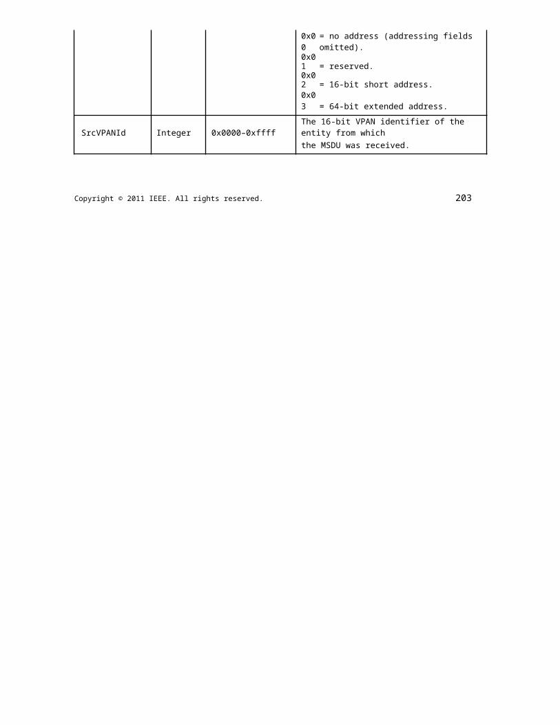
IEEE Std 802.15.7r1-20xx IEEE STANDARD FOR SHORT-RANGE WIRELESS
the centroid of the triangle IJK. The absolute values for 4-CSK for multiple combinations of the optical sources assuming the spectral peak of the optical source is at the center of the bandplan can be obtained in Yokoi, et al. [B17].
Figure 245—Con-stellation design rule for 4-CSK
13.5.2 Design rule for 8-CSK
8-CSK symbol points are defined by the design rule in Figure 245. Points I, J, and K show the center of the three color bands on xy color coordinates in Table 133. S0 to S7 are 8 symbol points of 8-CSK. S0, S4, and S7 are three vertices of the triangle IJK. S1 and S2 are points that divide side JK and side JI in the ratio 1:2. Point B and C are midpoints of the line JI and line JK. S6 is a midpoint of the line KI. Point A is the centroid of the triangle B-S6-I. Point D is the centroid of the triangle C-K-S6. S3 is a point that divides line AB in the ratio 1:2. S5 is a point that divides line DC in the ratio 1:2.
The absolute values for 8 -CSK for multiple combinations of the optical sources assuming the spectral peak of the optical source is at the center of the bandplan can be obtained in Yokoi, et al. [B17].
412 Copyright © 20xx IEEE. All rights reserved.
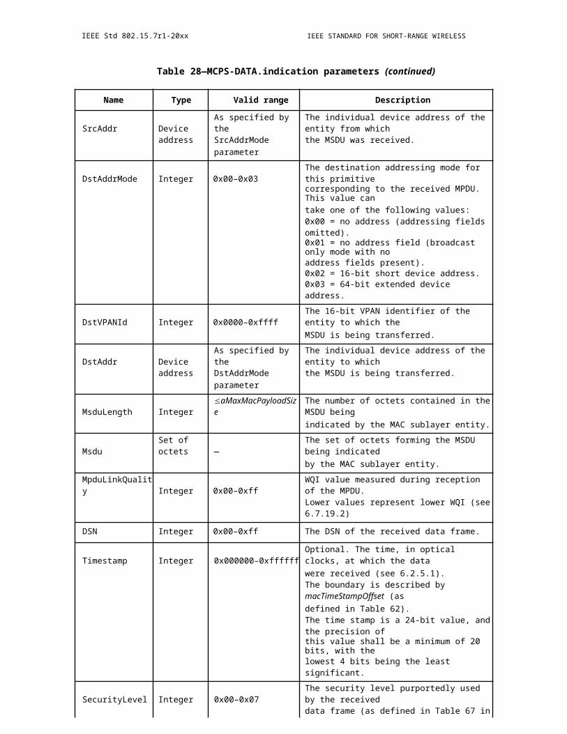
OPTICAL COMMUNICATION IEEE Std 802.15.7r1-20xx
Figure 246—Constellation design rule for 8-CSK
13.5.3 Design rule for 16-CSK
16-CSK symbol points are defined by the design rule in Figure 246. Points I, J, and K show the center of the three color bands on xy color coordinates in Table 133. S0 to S15 are 16 symbol points of 16-CSK. S5, S10, and S15 are three vertices of the triangle IJK. S2 and S8 are points that divide side JK in one third. S3 and S12 are points that divide side JI in one third. S11 and S14 are points that divide side KI in one third. S0 is the centroid of the triangle IJK. S1, S4, S6, S7, S9, and S13 are the centroids of each of the smaller triangles. The absolute values for 16-CSK for multiple combinations of the optical sources assuming the spectral peak of the optical source is at the center of the bandplan can be obtained in Yokoi, et al. [B17].
Figure 247—Constellation design rule for 16-CSK
Copyright © 2011 IEEE. All rights reserved. 413
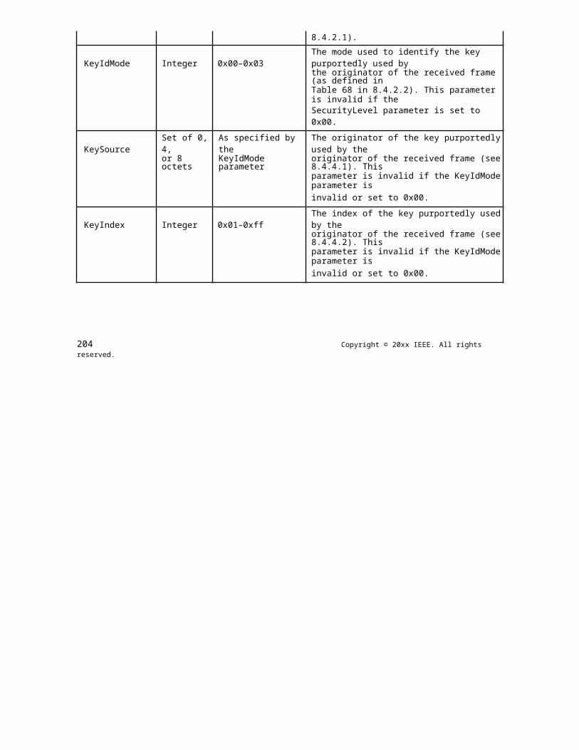
IEEE Std 802.15.7r1-20xx IEEE STANDARD FOR SHORT-RANGE WIRELESS
13.6 Data mapping for CSK
4-CSK data mapping is shown in Figure 247. Two bits are assigned per symbol.
CSK constellationi bandj bandk band
[0 0]CSK
Symbols
yy △
[0 1]
[1 0] [1 1]
△xx
Figure 248—Datamapping for 4-CSK
8-CSK data mapping is shown in Figure 248. Three bits are assigned per symbol.
CSK constellationi bandj band
[1 0 0]
k bandCSK Symbols
[0 0 0] [1 1 0]
y△ y
[0 0 1] [0 1
[1 0 1] [0 1 1] [1 1]
△xxFigure 249—Data
mapping for 8-CSK
16-CSK data mapping is shown in Figure 249. Four bits are assigned per symbol.
414 Copyright © 20xx IEEE. All rights reserved.
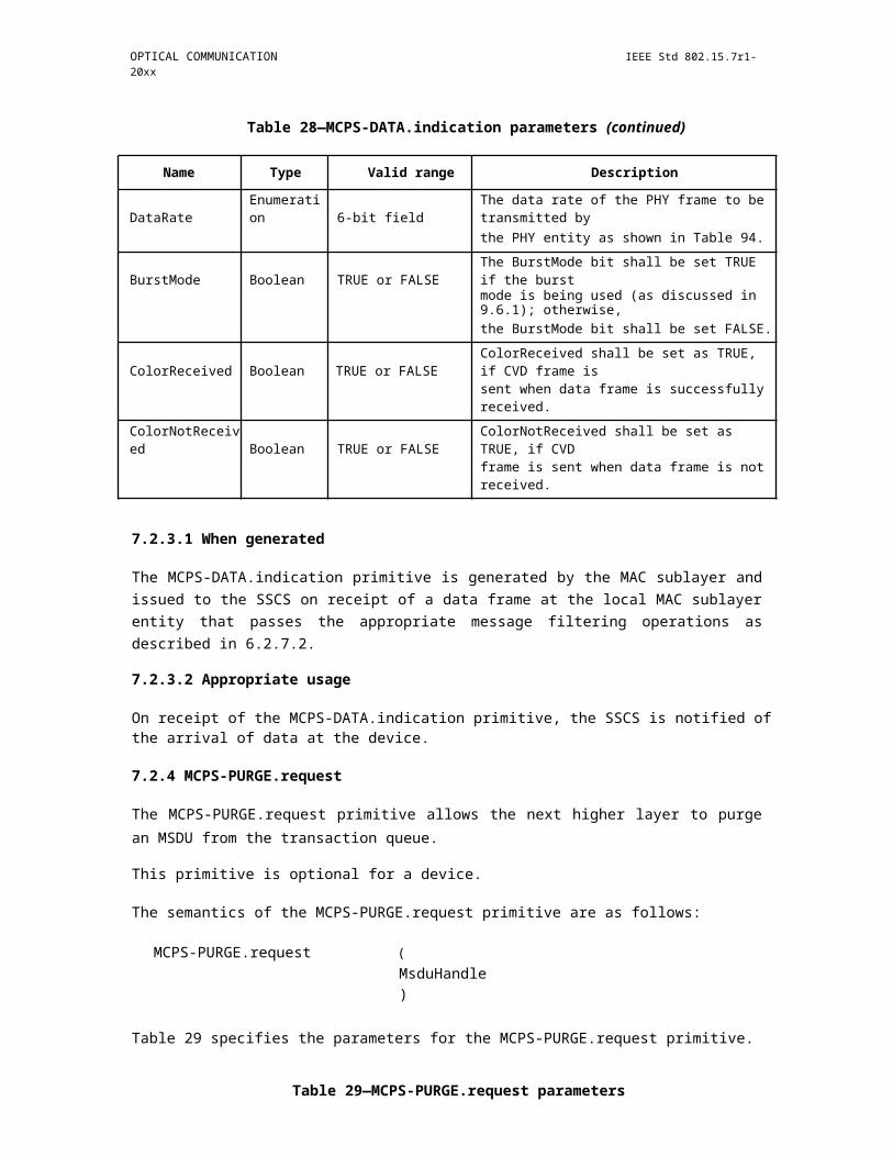
OPTICAL COMMUNICATION
CSK constellationi bandj band
[0 0 0 0]
k bandCSK Symbols
0 1][0 0 1 [0 1 0 1]
△ y
1 0] 1 1 1][1 0 1 [0 1 1 0] [0 1 0 0]
0 1 1] [1 1 1 0] [1 0 1]
[1 0 0 1] [1 1 1 1] [1 1 0 0] [1 0 0 0]
△xx
mapping for 16-CSK
IEEE Std 802.15.7r1-20xx
Figure 250—Data
13.7 Valid color band combinations
The CSK constellation is decided by the combination of the three color bands. Certain combinations that cannot make a triangle on the xy color coordinates are excluded, such as (110-101-100) or (100-011-010). Table 134 shows valid color band combinations that can make triangles for CSK constellations.
Table 134—Valid color band combinations for CSK
Band i Band j Band k
1 110 010 000
2 110 001 000
3 101 010 000
4 101 001 000
5 100 010 000
6 100 001 000
7 011 010 000
8 011 001 000
9 010 001 000
Figure 250 shows an example of the CSK constellation triangle when color codes (110, 010, 000) are used.
Copyright © 2011 IEEE. All rights reserved. 415

IEEE Std 802.15.7r1-20xx IEEE STANDARD FOR SHORT-RANGE WIRELESS
y
001Band j
010
011100101110 Band i
Band k
xFigure 251—Valid CSK constellation example for codes (110, 010, 000)
Table 135 shows color band combination and the xy coordinate values when color codes (110, 010, 000) are used. Figure 251 shows the CSK constellation points when color codes (110, 010, 000) are used.
CSK constellation CSK constellationCSK constellation CSK constellation
i band i band
0.8j band
0.8j band
k band k band
0.6
CSK Symbols
0.6
CSK Symbols
y 0.4 yy 0.4
0.20.2
0 0
-0.2 -0.2-0.2 0 0.2 0.4 0.6 0.8 1
0 0.20.4 0.6 0.8 1-0.2
x x
4 CSK 8 CSK
CSK constellationCSK constellation
i band j band 0.8 k band
CSK Symbols0.6
y 0.4
0.2
0
-0.20 0.2 0.4 0.6 0.8 1-0.2
x16 CSK
Figure 252—CSK constellation made by color band combinations
416 Copyright © 20xx IEEE. All rights reserved.
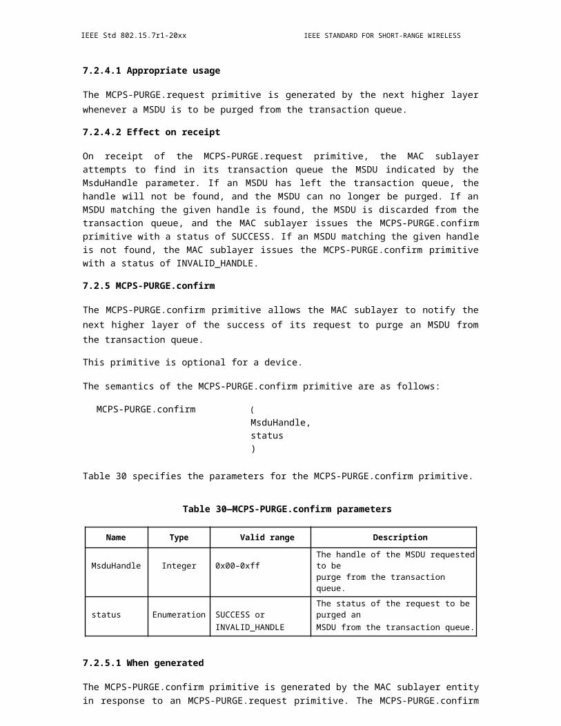
OPTICAL COMMUNICATION IEEE Std 802.15.7r1-20xx
Table 135—Color band combination example for (110, 010, 000)
Center of band xy coordinate values of symbols(x,y)
4-CSK 8-CSK 16-CSK[data] – (xp,yp) [data] – (xp,yp) [data] – (xp,yp)
(0.734 0.265) [0 0] – (0.402 0.597) [0 0 0] – (0.324 0.400) [0 0 0 0] – (0.402 0.597)(0.402 0.597) [0 1] – (0.435 0.290) [0 0 1] – (0.297 0.200) [0 0 0 1] – (0.413 0.495)(0.169 0.007) [1 0] – (0.169 0.007) [0 1 0] – (0.579 0.329) [0 0 1 0] – (0.335 0.298)
[1 1] – (0.734 0.265) [0 1 1] – (0.452 0.136) [0 0 1 1] – (0.324 0.400)[1 0 0] – (0.402 0.597) [0 1 0 0] – (0.623 0.376)[1 0 1] – (0.169 0.007) [0 1 0 1] – (0.513 0.486)[1 1 0] – (0.513 0.486) [0 1 1 0] – (0.435 0.290)[1 1 1] – (0.734 0.265) [0 1 1 1] – (0.524 0.384)
[1 0 0 0] – (0.734 0.265)[1 0 0 1] – (0.169 0.007)[1 0 1 0] – (0.247 0.204)[1 0 1 1] – (0.258 0.101)[1 1 0 0] – (0.546 0.179)[1 1 0 1] – (0.634 0.273)[1 1 1 0] – (0.546 0.179)[1 1 1 1] – (0.357 0.093)
Copyright © 2011 IEEE. All rights reserved. 417
IEEE Std 802.15.7r1-20xx IEEE STANDARD FOR SHORT-RANGE WIRELESS
13.8 CSK color mapping
Figure 252 shows the CIE1931 xy color coordinates (CIE 1932 [B13]) with the color mapping for 4-point CSK (4CSK). In this case, four color points are defined.
y
G(xj,yj)00
01
(xp,yp) 11 R(xi,yi)
10
B(xk,yk) x
Figure 253—CIE 1931 xy color coordinates
The points (xi,yi), (x j,yj), ( xk,yk) shows the xy coordinates of three light sources. The point (xp,yp) shows the one of the allocated color points in 4-CSK. The color point (x p,yp) is generated by the intensity of the three light sources Pi, Pj, and P k in Figure 241. These xy values are transformed into intensity Pi, Pj, and Pk. The relation between the coordinates and the intensity is shown in Equation (6). In the receiver side, xy values are calculated from the received light powers of three colors, and xy values are decoded into the received data.
x p Pi xi Pj x j Pk xk
y p Pi yi Pj y j Pk yk (6)
Pi Pj Pk 1
13.9 CSK calibration at the receiver
The VLC system could have some degradation, for example, multi-color imbalance, multi-color interference, or other error on xy color coordinates caused by ambient light or the light device characteristics; therefore, a CSK compensation method at the receiver is provided in the standard using color calibration for performance improvement. Figure 253 shows the CSK system with color calibration.
418 Copyright © 20xx IEEE. All rights reserved.
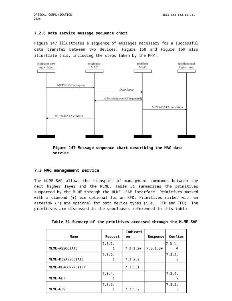
OPTICAL COMMUNICATION IEEE Std 802.15.7r1-20xx
xPi
xycolor Pjdata
yto
coding Pi,Pj,PkPk
channelestimationsequence
opticalsources photo detectors
D/A bandi bandi’ A/D Pi’
D/A bandj bandj’ A/DPj’
D/A bandk bandk’ A/DPk’
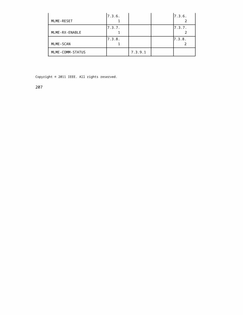
Pih
ii h
ijh
ik1
Pi h
jj
Pj h
jih
jk Pj
hkj
Pk
h
kih
kk Pk Pi
xRGB RGB colorPjcompensation todatay decodingxy
Pk
h h h channel ii ij ik estimation
hji
hjj
hjk
h h h ki kj kk
Figure 254—CSK system with color calibration
Before data communication, the system estimates the channel propagation matrix using sequences included in the channel estimation sequence. The channel propagation matrix is a matrix as shown in Equation (7).
hii
hij
hik
h jj
h
jih
jk
hkj
h
kih
kk
orthogonal 3x3 square
(7)
The propagation deviation can be compensated by multiplying the received signal with the inverted channel matrix as shown in Equation (8).
Pi hiih
ijh
ik 1 Pi Pj
h
jih
jj h
jk Pj (8)
h h Pk
h Pk
ki kj kk
Walsh codes shall be used for channel estimation as shown in Figure 254. During the transmission of the channel estimation sequence, the light sources are modulated with OOK according to the Walsh codes. Three Walsh code sequences of length 4 are provided for the three bands used for CSK. W(1,4) = {1,–1,1,– 1}, W(2,4) = {1,1,–1,–1}, W(3,4) = {1,–1,–1,1} are the three Walsh codes that shall be used for channel estimation. W(1,4), W(2,4) and W(3,4) shall be used for band i, j, k respectively. Each bit of the Walsh code shall be transmitted twice. Accurate channel estimation can be obtained by averaging the two bits.
Copyright © 2011 IEEE. All rights reserved. 419

IEEE Std 802.15.7r1-20xx IEEE STANDARD FOR SHORT-RANGE WIRELESS
Figure 255—Walsh codes for color calibration
14. PHY A specifications
14.1 Undersampled Frequency Shift ON-OFF Keying (UFSOOK)
14.1.1 Reference modulator diagram
A reference implementation of the modulator is shown in Figure TBD.
<PUT UFSOOK REFERENCE DIAGRAM HERE>
14.1.2 UFSOOK Encoder
Encode bits as OOK frequencies (ON-OFF blinking LED) such that
a) logic zero: represented by a OOK frequency that is an integer multiple of the camera frame rate.b) logic one: represented by an OOK frequency that is an integer multiple ½ of the camera frame rate.
When undersampled by the camera (appropriately fast exposure setting), the OOK frequencies alias to
a) logic zero: aliases to a steady state light (either ON or OFF)b) logic one: aliases to a blinking light at ½ the camera frame rate
The video frame-to-frame decoding rules are summarized below.
a) Aliased light is unchanging represents a logic "0"b) Aliased light is toggling represents a logic "1"
Adhering to the stated rules will always result in there being an even number of cycles of OOK per bit for a space frequency and an odd number of cycles for a mark frequency; hence, the "code" is always balanced.
420 Copyright © 20xx IEEE. All rights reserved.
OPTICAL COMMUNICATION IEEE Std 802.15.7r1-20xx
Figure 256—Example of how bit are sent using UFSOOK
14.1.3 UFSOOK Spatial FEC
Spatial redundancy forward error correction may be applied for UFSOOK by repeating each data frame over multiple LEDs, each with a slight time delay.
Copyright © 2011 IEEE. All rights reserved. 421

IEEE Std 802.15.7r1-20xx IEEE STANDARD FOR SHORT-RANGE WIRELESS
Figure 257—UFSOOK Spatial FEC
14.1.4 UFSOOK Temporal FEC
Temporal redundancy forward error correction may be applied for UFSOOK by serially repeating each data frame over a single LED, each repetition with a slight time delay.
422 Copyright © 20xx IEEE. All rights reserved.
OPTICAL COMMUNICATION IEEE Std 802.15.7r1-20xx
Figure 258—UFSOOK Temporal FEC
14.2 Twinkle VPPM
14.2.1 Reference modulator diagram
A reference implementation of the modulator is shown in Figure TBD.
<PUT UFSOOK REFERENCE DIAGRAM HERE>
14.2.2 VPPM Encoder
Encode bits using VPPM with one of two duty cycle. The duty cycles are either 1/3 of a symbol time or 2/3 of a symbol time. The twinkle is generated by alternating between the two duty cycles.
Copyright © 2011 IEEE. All rights reserved. 423
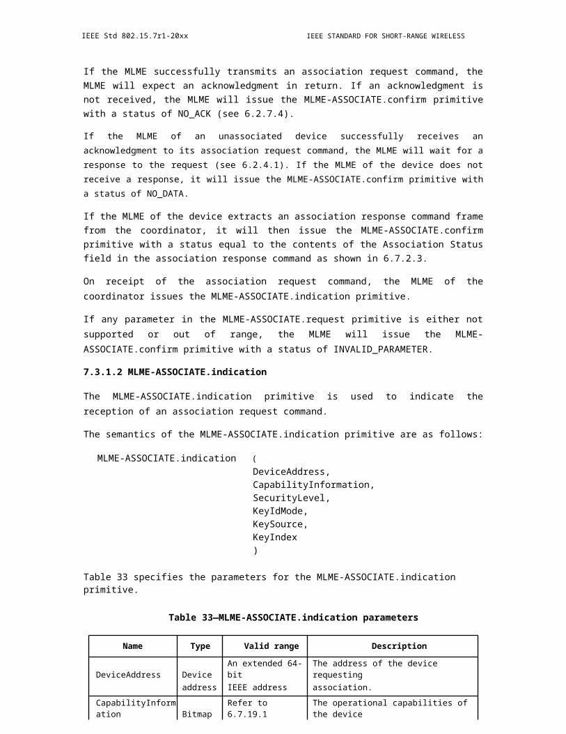
IEEE Std 802.15.7r1-20xx IEEE STANDARD FOR SHORT-RANGE WIRELESS
Figure 259—Composite Waveform with Twinkle
The VVPM bit encoding is shown below.
424 Copyright © 20xx IEEE. All rights reserved.

OPTICAL COMMUNICATION IEEE Std 802.15.7r1-20xx
Figure 260—Composite waveform VPPM bit definition
a) logic zero: pulse located on the left side of the symbol period.b) logic one: pulse located on the right side of the symbol period.
When undersampled by the camera (appropriately fast exposure setting), the OOK frequencies alias to
a) logic zero: aliases to a steady state light (either ON or OFF)b) logic one: aliases to a blinking light at ½ the camera frame rate
The video frame-to-frame decoding rules are summarized below.
a) Aliased light is unchanging represents a logic "0"b) Aliased light is toggling represents a logic "1"
Adhering to the stated rules will always result in there being an even number of cycles of OOK per bit for a space frequency and an odd number of cycles for a mark frequency; hence, the "code" is always balanced, as shown in Figure 255.
14.2.3 Twinkle generation
The desired “aliased twinkle frequency” is ¼ the camera frame rate. For a 30 fps camera this would be 7.5 Hz. In this way we are guaranteed to generate the twinkle frequency even if every other sample falls on a transition boundary. The possible AM envelope frequencies are
F =
1
Ffps
n --
4where n is an integer.
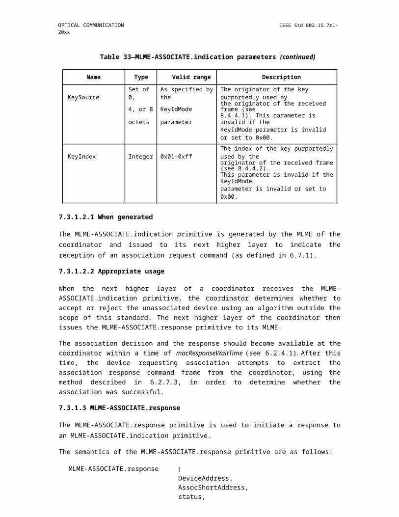
Copyright © 2011 IEEE. All rights reserved. 425
IEEE Std 802.15.7r1-20xx IEEE STANDARD FOR SHORT-RANGE WIRELESS
For example, given a 24 fps camera and n=4 one possible amplitude modulation frequency would be 4.25*24=102 Hz.
Using the VPPM bit definitions, alternately transmit 2/3 duty cycle bits for half an AM envelope cycle fol-lowed by 1/3 duty cycle bits for the second half AM envelope cycle. Round to an integer number of trans-mitted bits per half cycle.
For the above example, we’d alternate between duty cycles every 1/204 seconds.
14.2.4 Twinkle VPPM FEC
TBD
14.3 S2-PSK
14.3.1 S2-PSK Encoder
14.3.1.1 Bit definition (Encoding):
1) Same frequency and amplitude2) Inverse phase (bit 1 phase = 0; bit 0 phase = 180)
Figure 261—Graphic of reference LED and Bit 1/0 Definition goes here
14.3.1.2 Decoding principle (applied for a random sampling):
a) The state of bit 1 is always equal to the state of the reference signal (x1 = xr)b) The state of bit 0 is always inverse to the state of the reference signal (x0 = not(xr))
426 Copyright © 20xx IEEE. All rights reserved.
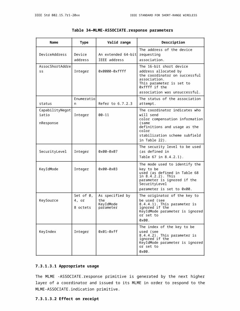
OPTICAL COMMUNICATION IEEE Std 802.15.7r1-20xx
14.3.1.3 Decoding example:
Figure 262—Insert Related Graphic Here
14.3.1.4 Compatibility support
a) The decoding result is non-affected by the state of the LEDs but by the comparison. This means a receiver does not need to know which LED is a reference LED and which one is data LED; data is output from a comparison.
b) The principle is compatible to different frame rate variation.
14.3.2 S2-PSK Error Correction
Figure 263—Insert Related Graphic Here
14.3.2.1 Modulation considered
a) Modulation frequency is less than the global shutter speed of the camera (e.g. 1kHz)b) The long exposure causes error (BER)
Error is caused by long exposing time in a global shutter camera receiver
An outer FEC code is required to correct the error.
14.3.3 S2-PSK Dimming Support
No dimming support is considered in this scheme. The brightness is constant at 50%.
Amplitude Modulation can be used in order to dim the light if necessary. This is reasonable because the
Copyright © 2011 IEEE. All rights reserved. 427
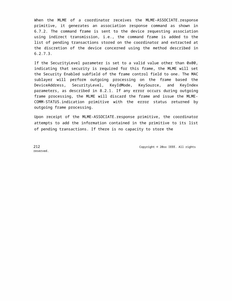
IEEE Std 802.15.7r1-20xx IEEE STANDARD FOR SHORT-RANGE WIRELESS
optical clock rate to modulate all LEDs is constant throughout transmitting time.
14.4 S2+DMS-PSK
14.4.1 DSM-PSK
14.4.1.1 S8-PSK
14.4.1.1.1 S8-PSK Encoder
A group of four-LEDs is used to transmit a phase which encoded by 3-bits data. A
Spatial Phase (of a LEDs group): is defined by a four-sates set of a LEDs group.
Figure 264—Spatial-Phase Definition Table
14.4.1.1.2 Encoding:
A Global Phase Shift of a group of data LEDs determines how LEDs are modulated. It is generated accord-ing to 3bits data input.
Decoding table - case 1 (none bad-sampling)
Figure 265—Encoding and Decoding Table
428 Copyright © 20xx IEEE. All rights reserved.

OPTICAL COMMUNICATION IEEE Std 802.15.7r1-20xx
14.4.1.1.3 Decoding:
S_Phase Shift = S_Phase(data) – S_Phase(reference)
Case 1: Decoding under none-presence of bad-sampling
Decoding tables (none bad-sampling) are used
Figure 266—Decoding under none-presence of bad-sampling
Case 2: Decoding under presence of bad-sampling
Figure 267—Decoding under presence of bad-sampling
Decoding tables (presence of bad-sampling) are used
14.4.1.1.4 S8-PSK Error Correction
Error caused by bad-sampling (long exposure time): is corrected by a redefined decoding tables Re-defined
Decoding table - case 2 (presence of bad-sampling)
Copyright © 2011 IEEE. All rights reserved. 429
IEEE Std 802.15.7r1-20xx IEEE STANDARD FOR SHORT-RANGE WIRELESS
Figure 268—Re-defined Decoding Table
The correction of bad-sampling error does not require any line/space coding; hence no reduce to data rate.
Additionally, an outer FEC code can be used. See IEEE 802.15.7 standard for generating outer code.
14.4.1.1.5 S8-PSK Dimming Support
No dimming support is considered in this scheme. The brightness is constant at 50%.
Amplitude Modulation can be used in order to dim the light if necessary. This is reasonable because the opti-cal clock rate to modulate all LEDs is constant throughout transmitting time.
14.4.1.2 DS8-PSK
14.4.1.2.1 DS8-PSK Encoder
Principles: 8 LEDs per group together define a spatial-phase (with dimming supported)
Figure 269—Definition of a spatial-phase with dimming support
Encoding
a) A reference group: Global Phase Shift = 0a) A data group: Global Phase Shift = 0/1/¡K/7
430 Copyright © 20xx IEEE. All rights reserved.

OPTICAL COMMUNICATION IEEE Std 802.15.7r1-20xx
Figure 270—Encoding and Decoding Tables
S_Phase Decoding table for DS8-PSK
Figure 271—S_Phase Decoding Table for DS8-
PSK 14.4.1.2.2 DS8-PSK Error Correction
Error caused by bad-sampling (long exposure time): is corrected by a redefined decoding tables (below). No reduce to data rate.
In addition, an outer FEC code is used. See IEEE 802.15.7 standard for generating outer code.
S_Phase Decoding Re-defined tables for DS8-PSK (presence of x_state in bad-sampling)
Figure 272—Re-defined tables for DS8-PSK
where x state (of a LED) is an unclear state that observed from a bad-sampled image.
Copyright © 2011 IEEE. All rights reserved. 431

IEEE Std 802.15.7r1-20xx IEEE STANDARD FOR SHORT-RANGE WIRELESS
14.4.1.2.3 DS8-PSK Dimming Support
Dimming is supported in steps of 1/8 (12.5%) in DS8-PSK scheme
The encoding table (to determine the global shift value of a data LEDs group) is common for all dimming level. Each dimming level is supported by a specific S_Phase decoding table (or a redefined table) that is different from the other dimming levels.
Decoding procedure under dimming condition:
Step 1: Choose the proper S_Phase decoding Table (among 7 tables) according to the dimming level:
a) Dimming level = £U "ƒN" ƒN (or = ƒNƒN£U "ƒN" ƒN under presence of x_state)b) Select the proper S_Phase decoding table
Step 2: Map with the selected decoding table to find S_Phase(data); S_Phase(reference) and S_Phase_Shift
Input: The discrete waveforms of a 8-LEDs groups (a reference group and data groups)
Output: Spatial Phases
a) S_Phase(reference)b) S_Phase(data)c) S_Phase_Shift = S_Phase(data) - S_Phase(reference)
Step 3: Data decoding using Phase-to-Bits table
Input: S_Phase_Shift
Output: 3 data bits
14.4.1.3 Twinkle VPPM
14.4.1.3.1 Twinkle S2-PSK and DS8-PSK Encoder
A twinkle signal (hybrid modulation scheme of S2-PSK and DS8-PSK) for a dual-camera system:
- A low frame rate camera (i.e. low cost camera) detects S2-PSK signal
The idea of a twinkle signal came from Intel. It was to support dual-cameras system. This section presents a same purpose in using dual-cameras; however by using Kookmin modulation schemes: a hybrid scheme of S2-PSK and DSM-PSK.
- Twinkle VPPM? Even though our modulation names are different (Spatial PSK), a modulated signal to a single LED is also a VPPM signal. So the technique title “Twinkle VPPM” is fine to us.
We respect and follow the title name.
o Can be either a global or a rolling shutter camera
o Can be either a slow exposer or a quick exposer camera. A higher shutter speed camera is better for remov-ing environmental noise and detecting LEDs.
- A high speed camera (i.g. a global shutter and high frame rate camera) decode data at DS8-PSK signal.
432 Copyright © 20xx IEEE. All rights reserved.

OPTICAL COMMUNICATION IEEE Std 802.15.7r1-20xx
Figure 273—Title for graphic goes here
14.4.1.3.2 Twinkle S2-PSK and DS8-PSK Error Correction
Error caused by bad-sampling (long exposure time): is corrected by a re-defined decoding tables in DS8-PSK scheme.
In addition, an outer FEC code can be applied, or just a repeat code for simple.
14.4.1.3.3 Twinkle S2-PSK and DS8-PSK Dimming Support
Dimming is supported by adjusting the low dimmed level and high dimmed level of DS8-PSK scheme to output a desired dimming level.
Output dimming level = ½ (low dimmed level + high dimmed level)
14.5 Offset-VPWM (SNUST 16/353r2)
14.5.1 1 PHY Layer Operating Mode(s) (move to clause 9.1)
The IEEE802.15.7r1 OWC TG ISC/L-PD PHY mode classification for Draft Document D0 is introducing the following three new PHY modes.
"PHY A - Discrete (or Singular) Source
"PHY B - Surface Source
"PHY C - 2-Dimensional / Screen Source
The SNUST Offset Variable Pulse Width Modulation for Smart Device Flash Light uses the PHY A - Singu-lar Point Source /Surface Light Source.
The IEEE802.15.7r1 PHY A Operating Modes system specifications are given in Table 1-1.
Copyright © 2011 IEEE. All rights reserved. 433
IEEE Std 802.15.7r1-20xx IEEE STANDARD FOR SHORT-RANGE WIRELESS
PHY A Operating Modes
Table 136—IEEE802.15.7r1 PHY Operating Mode for Offset Variable Pulse Width Modulation for Smart Device Flash Light
ModulationOptical Clock
FEC Dada RateRate
OffsetVPWM 100 Hz RS/CRC 12 bps
14.5.2 PHY Specifications
The IEEE802.15.7r1 PHY A with supported data rates and operating conditions is shown in Table 1-1 for Offset Variable Pulse Width Modulation for Smart Device Flash Light data transmission.
14.5.2.1 OFFSET-VPWM
The proposed Offset-VPWM (Variable Pulse Width Modulation) designed with following characteristics,
"Modulation methods includes line coding
"Defining the sum (P + nV) of the unit to be added to the minimum pulse (P) which is a reference pulse width (V) as a Symbol ( P>>V, V>time error(jitter) )
"Can specify a 2bit data symbol, 4bit data symbol according to number of added pulse
"Data is expressed with offset pulse width, 2bits data(for example) were mapped into 4 Offset-VPWM symbols
The data symbol map for two bits symbol with pulse width and respective symbol blinking waveform are shown in Table 2-1 and Figure 2-1 respectively.
Table 137—Two Bits Symbol Mapping Truth Table
Data bits Pulse width
00 P+0V
01 P+1V
10 P+2V
11 P+3V
434 Copyright © 20xx IEEE. All rights reserved.
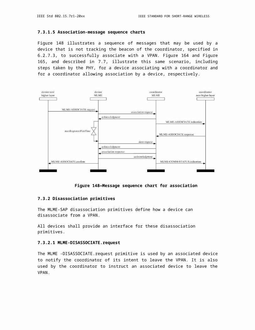
OPTICAL COMMUNICATION IEEE Std 802.15.7r1-20xx
Figure 274—Two Bit Symbol Data Diagram
In offset-VPWM, the data is expressed with offset pulse width, 4bits data (for example) were mapped into 16 Offset-VPWM symbols. The 4 bits symbol mapping truth table is shown in Table 2-2.
Table 138—Four Bits Symbol Mapping Truth Table
Data bits Pulse Width
The symbol arrays mapping is described in waveform pattern as shown in Figure 2-2.
Copyright © 2011 IEEE. All rights reserved. 435

IEEE Std 802.15.7r1-20xx IEEE STANDARD FOR SHORT-RANGE WIRELESS
Figure 275—Symbol Array Mapping Timing Diagram
14.5.2.2 Receiver Detection Method
Receiver can synchronize rising edge and check pulse width length using Rolling-shutter method. The receiver detection process in the wave formatted approach is show in Figure 2-3.
Figure 276—Receiver Detection Process
14.5.3 PHY Layer Dimming Method
In the Offset Variable Pulse Width Modulation for Smart Device Flash Light PHY uses the Smartphone Camera LED Flash light sources, no need concerning dimming. The Camera LED Flash light is no using for illumination and blinking speed is very low, then can't control dim.
o Symbol Length : P, P+V, P+2V, P+3V
The Figure 3-1 shows the 2bit symbol map dimming control for Offset Variable Pulse Width Modulation for Smart Device Flash Light.
436 Copyright © 20xx IEEE. All rights reserved.

OPTICAL COMMUNICATION IEEE Std 802.15.7r1-20xx
Figure 277—2 Bit Symbol Map Dimming Control
Figure 3-1 - 2 Bit Symbol Map Dimming Control
In accordance with the provisions of the symbol, depending on the data bit transmission because the High Pulse interval being determined brightness is adjustable (P >> V, V>time error (jitter)).
14.5.4 PPDU Format (move to clause 9.6)
The PPDU frame structure presented in IEEE802.15.7-2011 (Figure 118 - Format of the PPDU) is shown in Figure 4-1.
Figure 278—Format of the IEEE802.15.7-2011 PPDU
The IEEE802.15.7r1 PPDU frame structure is formatted as illustrated in Figure 4-2 for PHY-IV Rolling/ Global Shutter Cameras and Low Rate PD.
Figure 279—Format of the IEEE802.15.7r1 PPDU
Copyright © 2011 IEEE. All rights reserved. 437
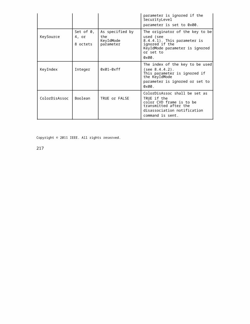
IEEE Std 802.15.7r1-20xx IEEE STANDARD FOR SHORT-RANGE WIRELESS
SHR Field:
The preamble field is used by the transceiver to obtain optical clock synchronization with an incoming mes-sage. The standard defines one fast locking pattern (FLP). The MAC shall select the optical clock rate for communication during the clock rate selection process. The preamble shall be sent at a clock rate chosen by the TX and supported by the RX. The preamble is a time domain sequence and does not have any channel coding or line coding.
The preamble first starts with a FLP. The FLP is fixed as a pattern "11010010". The fast locking pattern length shall not exceed the maximum. The timing information for preamble is shown in Figure 4-3.
Figure 280—Preamble Timing Diagram
In the Offset Variable Pulse Width Modulation for Smart Device Flash Light PHY uses OOK modulation for preamble transmission using flash light. The Preamble Bit Mapping shown in Figure 4-4.
Figure 281—Preamble Transmission - OOK BIT MAPPING
PSDU Field:
The PSDU field has a variable length and carries the data of the IEEE802.15.7r1 PHY frame. The FCS is appended if the PSDU has a non-zero byte payload. The structure of the PSDU field is as shown in Figure 4-5.
438 Copyright © 20xx IEEE. All rights reserved.
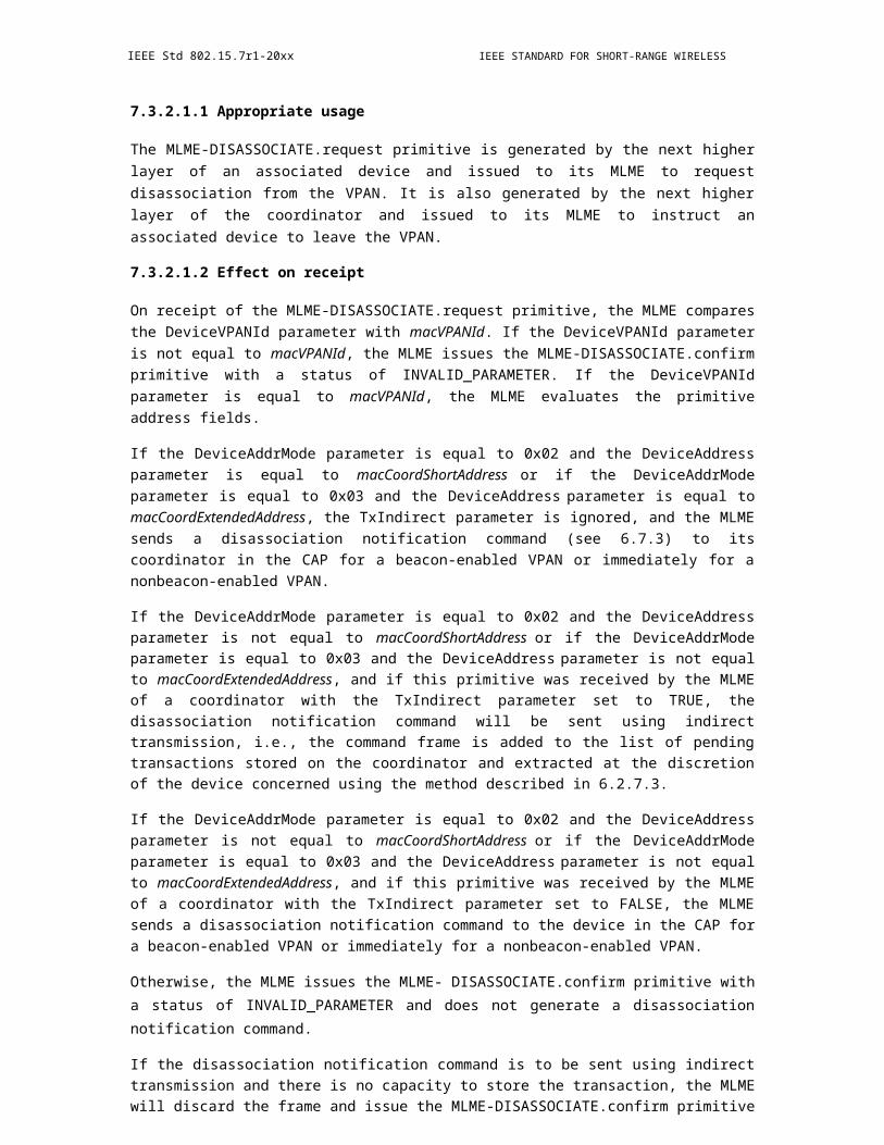
OPTICAL COMMUNICATION IEEE Std 802.15.7r1-20xx
Figure 282—IEEE802.15.7r1 PHY PSDU Field Structure
14.5.5 PHY PIB Attributes (move to clause 10.5)
The PHY PIB comprises the attributes required to manage the PHY sublayer of a device. The attributes con-tained in the IEEE802.15.7-2011 PHY PIB are presented in Table 100 - PHY PIB Attributes.
The additional PHY PIB attributes added on IEEE802.15.7r1 for Offset Variable Pulse Width Modulation for Smart Device Flash Light PHY is presented the Table 5-1.
Table 139—IEEE802.15.7r1 PHY PIB Attributes Additions
Attribute Identifier Type Range Description
This attribute specifies theapplication specific PHYmode.
phySMFlashLIGHTAp- 0 : Normal Data (Media
0x10 Unsigned 0~255 Content, InformationplicationSpecificMode Content based on the
Application used for)1 : ID Data2 : Authentication Data
14.5.6 Superframe Structure (move to 6.1)
The Super frame structure presented in IEEE802.15.7-2011 is shown in Figure 6-1.
Copyright © 2011 IEEE. All rights reserved. 439
IEEE Std 802.15.7r1-20xx IEEE STANDARD FOR SHORT-RANGE WIRELESS
Figure 6-1 - Superframe Structure
The Offset Variable Pulse Width Modulation for Smart Device Flash Light PHY uses the unslotted ALOHA; that is, when the Smart Device flash light transmitter has a packet to send, it just transmit the data. This sup-port with beacon and without beacon support and the transmitter does not do a listen before talk channel activity check.
The super frame structure for IEEE802.15.7r1 without beacon is shown in Figure 6-2.
Figure 283—IEEE802.15.7r1 Superframe Structure without Beacon
14.5.7 MAC Frame Formats (move to clause 6.4)
The MAC frame structure presented in IEEE802.15.7-2011 (Figure 44 - General MAC Frame Format) is shown in Figure 7-1.
440 Copyright © 20xx IEEE. All rights reserved.
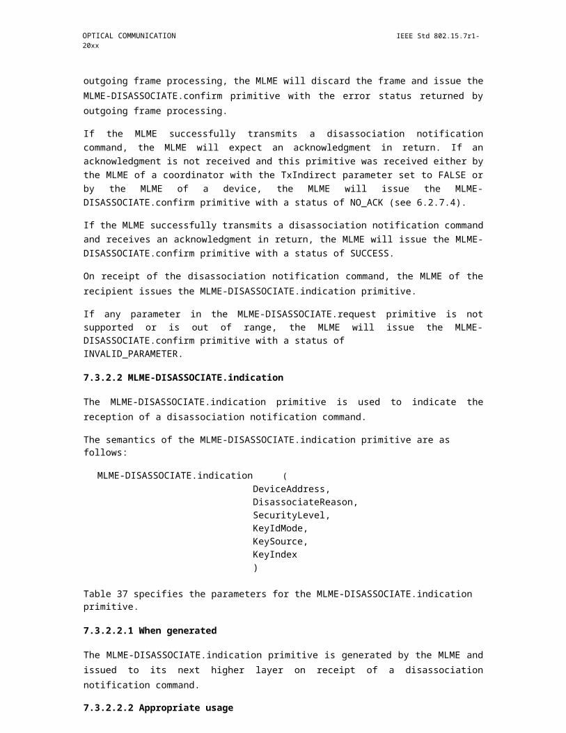
OPTICAL COMMUNICATION IEEE Std 802.15.7r1-20xx
Figure 284—General MAC Frame Format
The IEEE802.15.7r1 MAC frame structure is formatted as illustrated in Figure 7-2 for Offset Variable Pulse Width Modulation for Smart Device Flash Light.
Figure 285—IEEE802.15.7r1 MAC Frame Format
Frame Payload Field:
The Frame Payload field has a variable length and contains information specific to individual frame types. If the Security Enabled subfield is set to one in the frame control field, the frame payload is protected as defined by the security suite selected for that frame.
FCS Field:
The FCS field is 2 octets in length and the FCS is calculated over the MHR and MSDU parts of the frame. The FCS shall be only generated for payloads greater than zero bytes.
The FCS is option is given as an optional option, it is adaptive to RS/CRC/NONE.?
14.5.8 MAC PIB Attributes (move to clause 7.5)
The MAC PIB comprises the attributes required to manage the MAC sublayer of a device. The attributes contained in the IEEE802.15.7-2011 MAC PIB are presented in Table 60 - MAC PIB Attributes.
Copyright © 2011 IEEE. All rights reserved. 441

IEEE Std 802.15.7r1-20xx IEEE STANDARD FOR SHORT-RANGE WIRELESS
The additional MAC PIB attributes added on IEEE802.15.7r1 for Offset Variable Pulse Width Modulation for Smart Device Flash Light is presented the Table 8-1.
Table 140—IEEE802.15.7r1 MAC PIB Attributes Additions
Attribute Identifier Type Range Description Default
This attributeindicates thetype of datatransmittedusing Flash
macLEDI-0x81 Unsigned 0-255
Light Transmit-0Dusage ter.
0 : LED IT1 : With orWithout LEDID and IPaddress
14.6 CSM (withdrawn)
15. PHY B specifications
15.1 RS-FSK (rolling shutter frequency shift keying)
15.1.1 Rolling Shutter - Frequency Shift (RS-FSK) Transmitted Waveform
RS-FSK takes advantage of the rolling shutter sampling mechanism in the optical camera receiver, and therefore the "rolling shutter" prefix in the name. However, from the perspective of the transmitter, RS- FSK uses simple frequency shift keying (FSK) signal format. Firstly, a number of K frequencies are used to rep-resent a bit pattern of log_2?K bits. Secondly, the transmitter uses "square wave pulse shaping", i.e., it will only use two levels, an ON level and an OFF level. This allows us to avoids complex driving circuitry, in particular, a digital to analog converter (DAC), and reduces the cost of the transmitter. Moreover, it will also allow a clean stripe pattern observed in the captured image at the receiver side, which is utilized by the demodulation process. (Please see section 2.3 for a description of the relationship between the width of the strips observed in the pattern in the camera captured image).
442 Copyright © 20xx IEEE. All rights reserved.
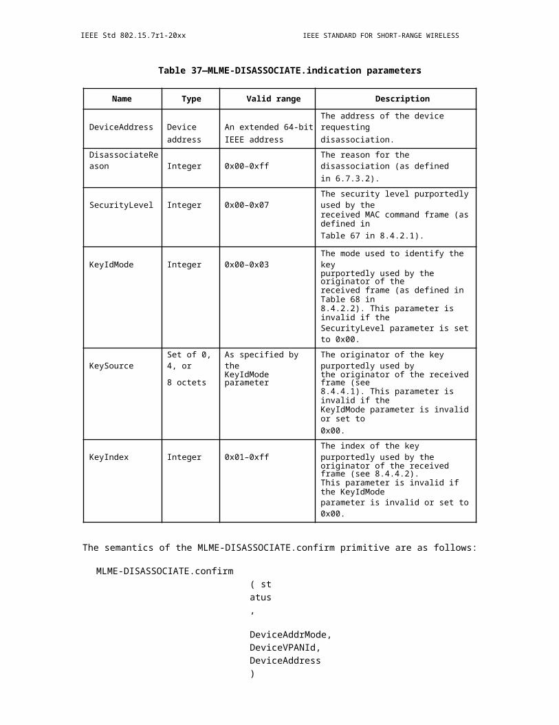
OPTICAL COMMUNICATION IEEE Std 802.15.7r1-20xx
Figure 286—RS-FSK signal waveform and camera captured image
15.1.2 Transmitted signal frequency
With the exception of the frequency used by the preamble, which is used to detect the start of a PPDU by the receiver, the actual set of frequencies used for data transmission is left to be determined by the user, based on the read-out time of the supported optical camera receiver (see section 2.3). It can be specified by the optical field of the PPDU (see section 4).
RS-FSK specifies the preamble frequency at 2.2 KHz. The majority of the commercially available image sensors have a read-out time of 20 to 30 microseconds. With this preamble frequency, the width of a pair of bright and dark strips in the observed stripe pattern in the camera captured image is between 15 and 23 pixels (see section 2.3 for the method to calculate this), and can be reliably detected. In addition, the obtained from the reception of the preamble frequency can be used to calibrate the value of the read-out duration, allowing better reception error performance.
For the set of frequencies used by the data symbols, it is recommended to use frequencies between 500 Hz and 1.4 KHz. The former corresponds to a strip width of 66 to 100 pixels while the latter corresponds to a stripe width of 23 to 36 pixels.
15.1.3 Symbol duration
RS -FSK uses a symbol duration that equals to the receiving camera's frame duration. Since most of the cameras use a frame rate of 30 frame per second when capturing video, the default symbol duration is set to be 1/30 second. Note that the symbol can be configured by the use of optional field and PIB attributes in PPDU (see section 5.2).
Copyright © 2011 IEEE. All rights reserved. 443
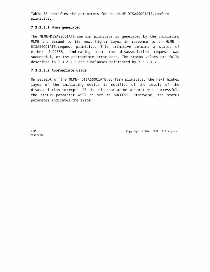
IEEE Std 802.15.7r1-20xx IEEE STANDARD FOR SHORT-RANGE WIRELESS
15.1.4 Relation between signal frequency and the observed strip width in the captured image
In this section we describe the relationship between the transmitted frequency f and the strip width W. Although the standard usually does not specify how the receiver demodulate the transmitted frequency, this background knowledge is required to determine the set of frequencies that is used by the transmitters based on the specification of the receiving optical camera. Therefore, we choose to disclose the information here.
The strip width is defined as the number of pixels occupied by a set of bright strip (exposure during the transmitter is in the ON state) and a dark strip (exposure during the transmitter is in the OFF state) in a received image. Note that, for a square wave of frequency f Hz, the duration of a complete cycle is 1/f sec-onds. Therefore, for every 1/f seconds a camera exposes, it should be able to read out a pair of bright and dark strips in the received image. On the other hand, the time a camera spends to read out a row of pixels is denoted as its read-out duration T_r. Denote the width of a bright strip as W_b and the width of a dark strip as W_d, and the width of a pair of bright strip and dark strip as W=(W_b+W_d). Therefore, in theory, the width of a pair of bright strip and dark strip can be found by W= (1/f)/T_ r =1/(fT_r ) (see Figure AB). Note that W is a real number. In practice, a receiver would need to observe the width of a large number of pairs of strips to calculate the average number of rows occupied by a pair of strips, W', as an estimate of W, and demodulate the symbol by f^'=1/(W^' T_r ).
15.1.5 Survey of parameters of commercially available image sensors
Figure 287—Relationship between transmitted RS-FSK signal frequency and the
We have carried out experiments to survey the parameters of common commercially available image sen-sors, and the results are summarized in Table 141.
Table 141—Read-out duration of cameras
ImageMeasured Gap between
Brand Product Name Frame Rate Read-out FramesResolution Duration (uS) (mS / %)
Apple iPhone 6 plus 1920x1080 30 21.42 10.20/30.60
Apple iPhone 5s 1920x1080 29.98 20.65 11.03/33.10
444 Copyright © 20xx IEEE. All rights reserved.
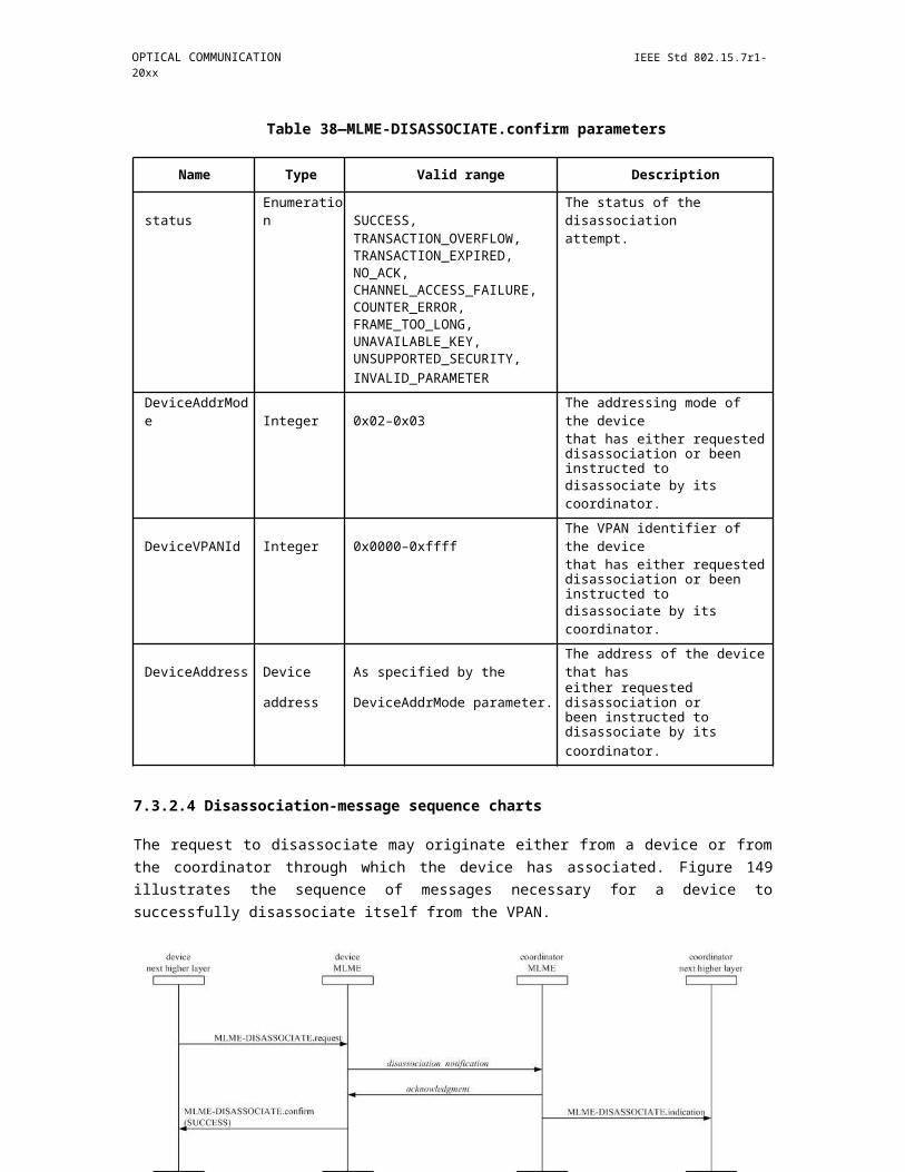
OPTICAL COMMUNICATION IEEE Std 802.15.7r1-20xx
Table 141—Read-out duration of cameras
ImageMeasured Gap between
Brand Product Name Frame Rate Read-out FramesResolution Duration (uS) (mS / %)
Apple iPhone 4s 1920x1080 29,87 24.48 7.04/21.03
HTC New One 1920x1080 29.94 19.08 12.79/38.30
Samsung Galaxy S4 1920x1080 29.93 25.53 5.84/17.48
From the table, we can see that most cameras have a read-out duration of 20-30 microseconds. This provides motivation for the selection of frequency used by RS-FSK.
15.2 Compatible M-FSK Modulation Scheme
Compatibility supports:
1) Frame rate variation2) Different sampling rates and shutter speeds
Figure 288—System Architecture for clock transmission approach in frequency domain
Definition
a) clock information (of a data packet): This scheme is similar to the C-OOK scheme in which asyn-chronous bits (Ab) represent the form of clock information. However, the data packet with clock information (called a symbol) is encoded using M-FSK technique.
b) Frequency symbol: a symbol modulated by a frequency to transmit a data packet
Copyright © 2011 IEEE. All rights reserved. 445
IEEE Std 802.15.7r1-20xx IEEE STANDARD FOR SHORT-RANGE WIRELESS
Figure 289—Data and clock information merging in frequency domain
FFT:
1) The peak value of the FFT spectrum is linear proportional to the modulation frequency of light
Figure 290—Spectrum peak and the corresponding frequency
measurement 15.2.1 CM-FSK asynchronous transmission
Figure 292—Data packet structure
a) A frequency symbol is hold a duration to transmit a data packetb) An asynchronous bit (represents the clock information of the data packet) is along with the packet
in transmission.
Frequency band:
446 Copyright © 20xx IEEE. All rights reserved.
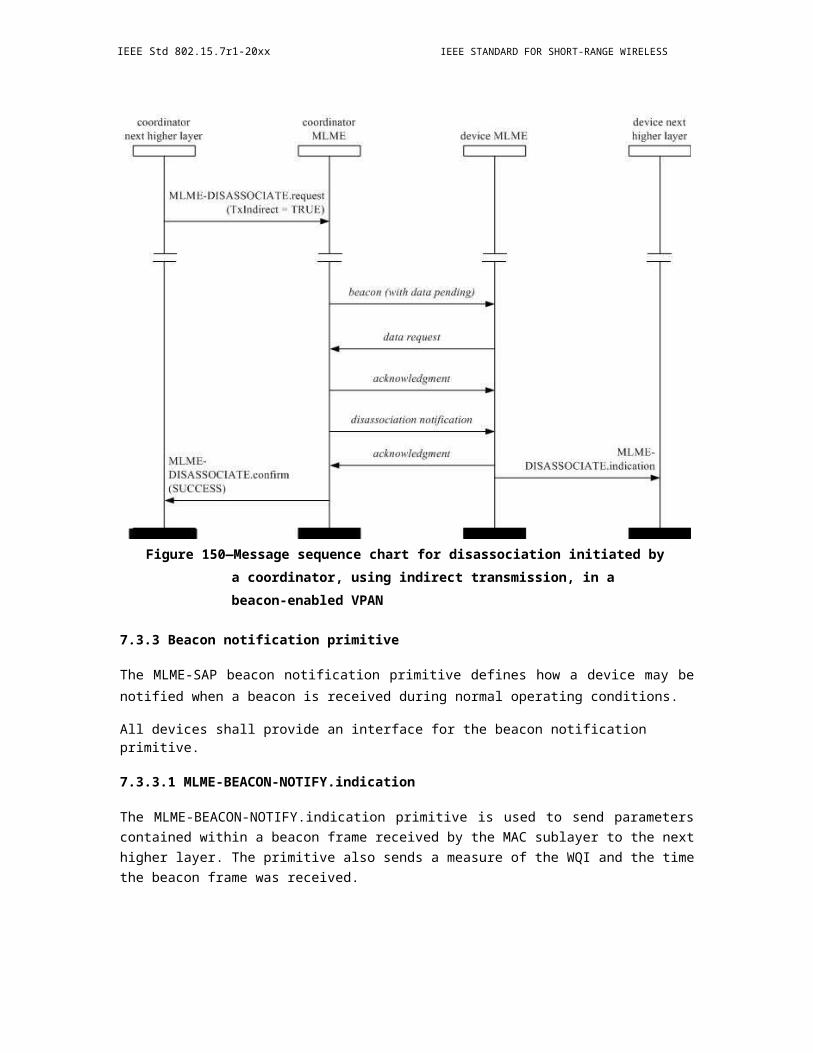
OPTICAL COMMUNICATION IEEE Std 802.15.7r1-20xx
Figure 293—Frequency band in use
15.2.2 32-FSK Modulation
a) Data frequency: fi = fSF + i.Äf (i=1; 2;…; 32)b) Preamble frequency: f’SF = fSF + 33.Äf
Figure 295—Symbol structure and C32-FSK encoding table 15.2.3 64-FSK
Modulation
Figure 296—Symbol structure and C64-FSK encoding table 15.2.4 Hybrid
Frequency-Phase Shift Keying
Advantages of M-FSK:
Copyright © 2011 IEEE. All rights reserved. 447

IEEE Std 802.15.7r1-20xx IEEE STANDARD FOR SHORT-RANGE WIRELESS
a) Support for multiple transmitters (LEDs). Frequency allocation is based on M-FSK to share the bandwidth to all LEDs. The M-FSK technique is to avoid interference efficiently.
b) Great support for rolling shutter receivers. The detection of frequency is much easier with rolling effect.
Additional advantage of N-PSK:
a) The N-PSK is additionally used to achieve higher data rate than just M-FSK. The higher link rate is helpful when a part of link rate must be shared for mitigating frame rate variation (by transmitting the asynchronous bits instead of data).
b) Additionally support for global shutter receivers (only 2-PSK, optional).
Figure 297—Hybrid modulation scheme: LEDs lighting design
15.3 C-OOK
Compatibility supports to various image sensors:
a) Frame rates variationb) Different sampling ratesc) Different rolling exposure times
Definition (move to Clause 3)
varying frame rate ISC mode: an ISC mode that supports a varying frame-rate receiver.
asynchronous decoding: a decoding procedure under presence of frame rate variation.
optical clock rate (modulation rate): The frequency at which the data is clocked out to the optical source. In flicker-free mode, let assume the frequency no less than 200Hz to be invisible to human eyes.
asynchronous bit: a form of clock information in the temporal scheme helping a varying frame rate receiver in asynchronous-decoding. Note that this is not only necessarily one single bit (bit 1 or bit 0), but also can be a symbol (a set of bits in which symbol 1 and symbol 0 are orthogonal somehow) to operate at high noise affected.
clock information (of a data packet/symbol): The information represents the state of a symbol clocked out. The clock information is transmitted along with a symbol to help a receiver identifying an arrival state of new symbol under presence of frame rate variation.
448 Copyright © 20xx IEEE. All rights reserved.
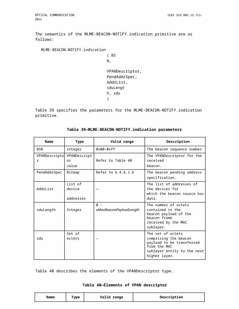
OPTICAL COMMUNICATION IEEE Std 802.15.7r1-20xx
rolling exposure time: the time from the first line to the last line exposes to light in a rolling shutter image sensor.
rolling sampling rate: how may row of pixels exposed to light in a rolling shutter camera
forward decoding: a decoding process in asynchronous decoding that taken from the position of the SF (preamble of the OOK data frame structure) backward on a rolling image.
backward decoding: a decoding process in asynchronous decoding that taken from the position of the SF (preamble of the OOK data frame structure) forward on a rolling image.
packet recovery: a process in asynchronous decoding that recovers a complete data packet from the incomplete data parts decoded, forward and backward part of one (two) data packet(s).
data fusion: a process in asynchronous decoding to group data parts (forward and backward parts) those belong to one packet. There are two types of data fusion that happens according to the value of asynchro-nous bits:
a) inter-frame fusion: to group data parts from different images (usually two images, but can be more than two)
b) intra-frame fusion: to group data parts from an image.
DS rate: the frequency at which the data subframe is clocked out to the transmission medium.
15.3.1 C-OOK asynchronous transmission
Figure 299—Data Packet Structure
Data packet Structure:
a) A packet is multiple times repeat of one data symbol.b) A complete DS has a very-low-header symbol (SF), two similar asynchronous bits (which is a form
of the clock information)
Table: Definition of SF symbol (Preamble symbol)
Copyright © 2011 IEEE. All rights reserved. 449
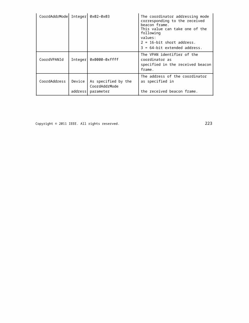
IEEE Std 802.15.7r1-20xx IEEE STANDARD FOR SHORT-RANGE WIRELESS
Table 142—Definition of SF symbol (Preamble symbol)
SF symbol (preamble) Ab Data Ab
011100 Manchester coding
0011111000 bit 1/0 4B6B coding bit 1/0
000011111111100000 8B10B coding (withdraw)
Definition of SF symbol (preamble):
a) A SF symbol is easily distinguished among data symbols. When the frame rate is varying irregu-larly, the position of the SF symbol on the rolling image is also varying. The detection of SFbecomes indispensable for the decoding (forward and backward parts) and recovering data.
b) The length of SF is different for each RLL code (in order to be low-overhead and detectable).
Note:
a) After proposal in January, we decide to withdraw 8B10B coding to reduce complexity in system implementation. The first page showed our final decision of PHY modes.
b) For this PHY 5, the PHY header shall be sent at optical clock rate 2.2kHz or 4.4kHz. Support for 2.2kHz optical clock rate is mandatory.
15.3.1.1 Asynchronous Decoding: Rolling exposure time >> (DS interval)
Figure 301—Decoding case 1
Decoding case 1: Oversampled Asynchronous decoding
a) This happens when the DS interval is short to be compatible to different rolling exposure timesb) The majority voting is applied between several images or within an image (using asynchronous
bits) to enhance BER.
450 Copyright © 20xx IEEE. All rights reserved.
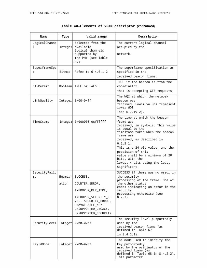
OPTICAL COMMUNICATION IEEE Std 802.15.7r1-20xx
15.3.1.2 Asynchronous Decoding: Rolling exposure time ~ (DS interval)
Figure 302—Decoding case 2
Decoding case 2: Forward decoding and Backward decoding
a) When the rolling exposure time is almost equal to DS interval, forward and backward are both used to get 100% information of an image.
b) The fusion of forward part and backward part (of a data packet) is performed to output a complete data packet.
15.3.1.3 Packet Recovery
Two cases may happen at different sampling time:
a) Case 1- Inter-frame data fusion: Fusing two sub-parts of a packet at two different images into a com-plete packet.
b) Case 2- Intra-frame data fusion: Recovering a complete packet from an image.
Figure 303—Packet recovery
15.4 3 mode PWM/PPM (Panasonic 16/365r0 - need to re-org this section)
THE INPUT WAS ONLY A FEW PAGES AND DUE TO TIGHT TIME CONSTRAINTS I PUT ALL THEINPUT INTO THIS ONE SECTION. THE MATERIAL NEEDS TO BE REDISTRIBUTED THROUGHOUTTHE DOCUMENT. - RICK
Copyright © 2011 IEEE. All rights reserved. 451

IEEE Std 802.15.7r1-20xx IEEE STANDARD FOR SHORT-RANGE WIRELESS
15.4.1 PHY Layer Operating mode(s) (move to Clause 9.1)
Table 143—PHY Operating Modes
PHY Operating Modes
Modulation RLL Code Optical Clock Rate FEC (Typical) Date Rate
Packet PWM None 100 kHz Temporal repeat code 5.5 kbps
Packet PPM None 100 kHz Temporal repeat code 8 kbps
15.4.2 PHY specifications
15.4.2.1 Packet PWM
Packet PWM is modulated with pulse width and pulse is shown as two state of brightness, bright and dark state, which are typically transmitted by on and off of a light. A chunk of PHY signal, which is called a packet, corresponds to a MAC frame. A transmitter transmits PHY packet repetitively and can transmit a set of PHY packets in no particular order.
15.4.2.2 Packet PPM
Packet PPM is modulated with position of short pulse. Packet PPM realizes deep dimming. Formats, wave forms and characteristics other than specially described are given same as Packet PWM.
15.4.3 PHY Layer Dimming Method (move to clause 9.5)
Dimming level is controlled by averaged brightness of the Optional field.
15.4.4 PPDU format (move to clause 9.6)
15.4.4.1 PPDU format of Packet PWM
Packet PWM consists of SHR, PHY payload A, PHY payload B, SFT, and Optional fields as shown in Fig-ure 1.
452 Copyright © 20xx IEEE. All rights reserved.
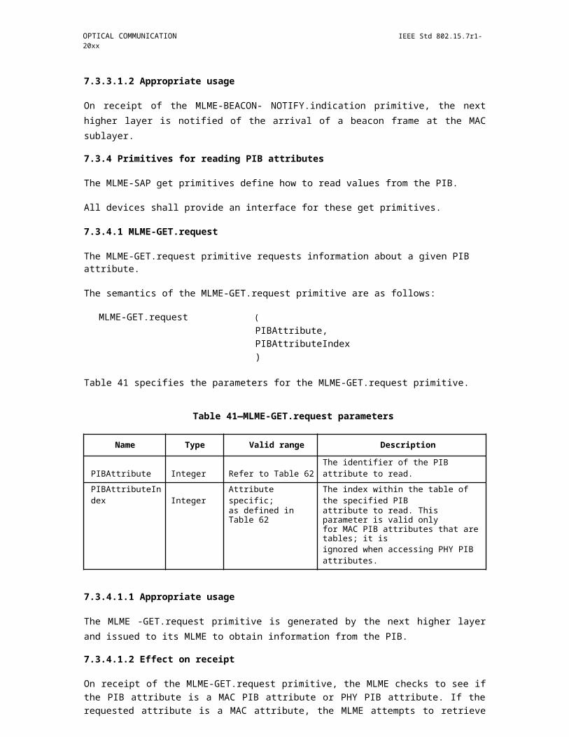
OPTICAL COMMUNICATION IEEE Std 802.15.7r1-20xx
Figure 304—Packet PWM mode 1
Figure 305—Packet PWM mode 2
Figure 306—Packet PWM mode 3
SHR field consists of two or four pulses. Patterns of the pulse width show transmission mode as shown in the Table 1.
PHY payload contains of 6 bits of data (x0 - x5) in mode 1, 12 bits of data (x0 - x11) in mode 2, or variable bits of data (x0 - xn) in mode 3. Let yk are defined as
y_k=x_3k+x_(3k+1)×2+x_(3k+2)×4
In mode 1 and 2, they are modulated to pulse width [micro seconds] as
Copyright © 2011 IEEE. All rights reserved. 453
IEEE Std 802.15.7r1-20xx IEEE STANDARD FOR SHORT-RANGE WIRELESS
Table 144—SHR field patterns of Packet PWM
Mode of Packet PWM SHR pattern (uS)
Mode 1 (100, 90)
Mode 2 (100, 90, 90, 100)
Mode 3 (50, 40, 40, 50)
P_Ak=120+30 ×(7-y_k )
P_Bk=120+30×y_k
In mode 3, they are modulated to pulse width [micro seconds] as
P_Bk=100+20×y_k
In mode 1 and 2, PHY payload A and PHY payload B fields are half-optional. A transmitter can transmit both of them, one of them, or a part of them, i.e., PA3, PA4, PB1, and PB2 in mode 2.
In mode 3, PHY payload lasts until SFT or next SHR field is transmitted.
SFT field in mode 3 consists of pulses with (40, 50, 60, 40) micro seconds. SFT field is optional field. A transmitter can transmit next SHR field instead of SFT field.
Transmitter can transmit any kind of signal in Optional field. However, the signal must not contain SHR field pattern. Optional field can be used for DC compensation and dimming control.
15.4.4.2 PPDU format of Packet PPM (move to clause 9.6)
Packet PPM consists of SHR, PHY payload, SFT, and Optional fields as shown in Figure 2. Time length of the short bright pulse, shown as L in the Figure, is less than ten micro seconds.
Figure 307—Packet PPM mode 1
454 Copyright © 20xx IEEE. All rights reserved.
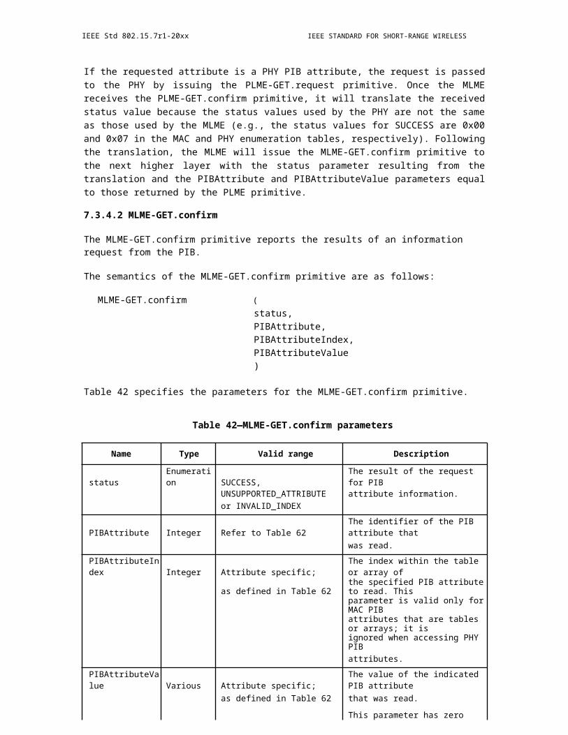
OPTICAL COMMUNICATION IEEE Std 802.15.7r1-20xx
Figure 308—Packet PPM mode 2
Figure 309—Packet PPM mode 3
SHR field consists of three intervals of successive four pulses. The patterns of intervals show transmission mode as shown in Table 2.
Table 145—SHR field patterns of Packet PPM
Mode of Packet PPM SHR pattern (uS)
Mode 1 (160, 160, 160)
Mode 2 (160, 180, 160)
Mode 3 (80, 90, 80)
PHY payload contains of 6 bits of data (x0 - x5) in mode 1, 12 bits of data (x0 - x11) in mode 2, or variable bits of data (x0 - xn) in mode 3. Let yk are defined as
y_k=x_3k+x_(3k+1)×2+x_(3k+2)×4
In mode 1 and 2, they are modulated to pulse width [micro seconds] as
P_k=180+30×y_k
In mode 3, they are modulated to pulse width [micro seconds] as
Copyright © 2011 IEEE. All rights reserved. 455
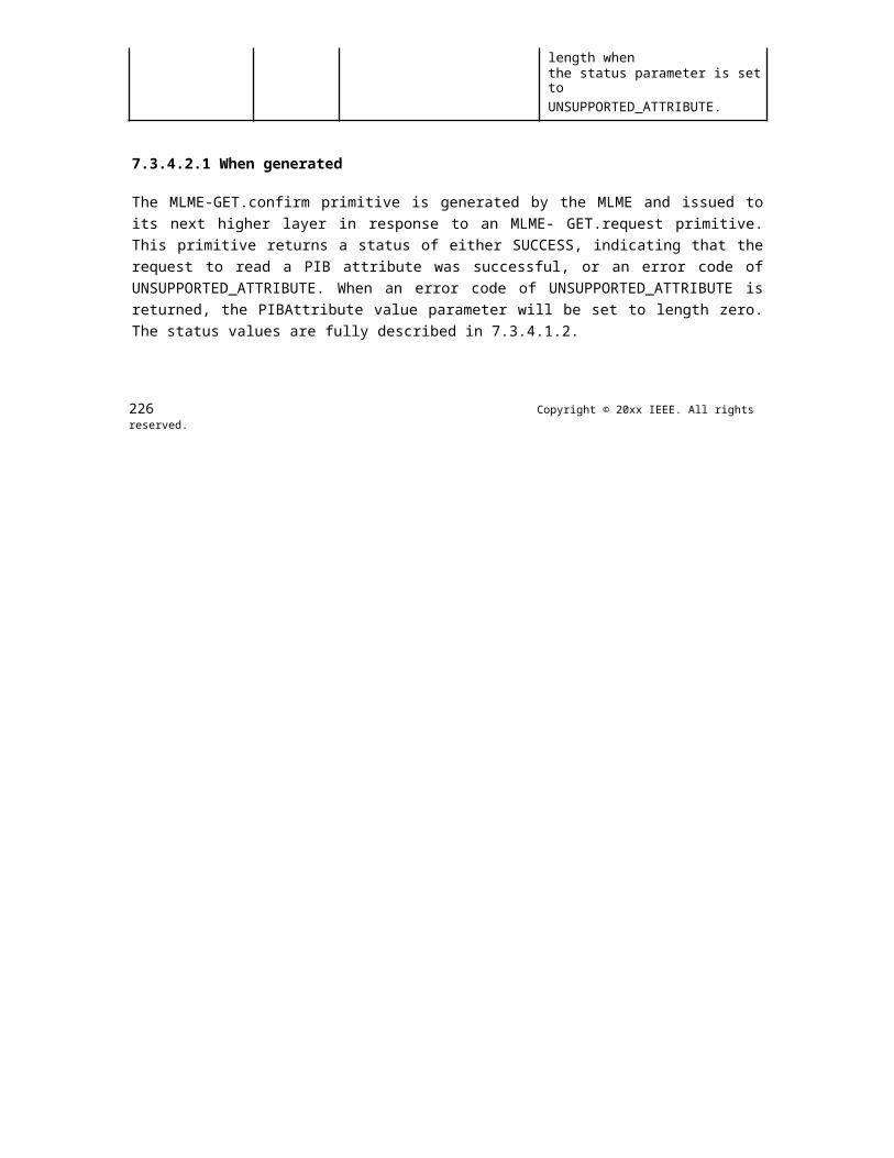
IEEE Std 802.15.7r1-20xx IEEE STANDARD FOR SHORT-RANGE WIRELESS
P_Bk=100+20×y_k
In mode 3, PHY payload lasts until SFT or next SHR field is transmitted.
SFT field in mode 3 consists of pulses intervals with (90, 80, 90) micro seconds. SFT field is optional field. A transmitter can transmit next SHR field instead of SFT field.
Transmitter can transmit any kind of signal in Optional field. However, the signal must not contain SHR field pattern. Optional field can be used for DC compensation and dimming control.
15.4.5 Superframe Structure (move to clause 6.1)
Packet PWM and Packet PPM does not have beacon nor superframe structure as same as UFSOOK.
15.4.6 MAC frame formats (move to clause 6.4)
15.4.6.1 MAC frame format of Packet PWM/PPM mode 1
PHY payload contains of 6 bits of data (x0 - x5). Packet address A (a0, a1) is represented as (x1, x4) and packet data D (d0, d1, d2, d3) is represented as (x0, x2, x3, x5).
MAC frame consists of 16 bits of data D00 D10 D01 D11, where Dk is data D of packet whose address A is k.
The native MPDU has too much overhead for this MAC frame and most of the fields are not needed for a short, repetitive MSDU. Therefore, this MAC frame does not have MHR field and the MFR field is optional.
15.4.6.2 MAC frame format of Packet PWM/PPM mode 2
PHY payload contains of 6 bits of data (x0 - x11) . A packet consists of address A (a0 - a3), data Da (da0 - da6), data Db (db0 - db3), and stop bit S (s). They correspond as
(?(x_0&x_1&x_2@x_3&x_4&x_5@x_6&x_7&x_8@x_9&x_10&x_11 ))=(?(d_a0&s&d_b0@d_a1&a_0/ d_a6&d_b1@d_a2&a_1/d_a5&d_b2@d_a3&a_2/d_a4&a_3/d_b3 ))
x4, x7, x10, and x11 correspond either of them in accordance with the packet division rule described below.
MAC frame is divided into some packets as shown in Figure 3.
Figure 310—1-division (No division) pattern
456 Copyright © 20xx IEEE. All rights reserved.

OPTICAL COMMUNICATION IEEE Std 802.15.7r1-20xx
Figure 311—2-division pattern
Figure 312—3-division pattern
Figure 313—4-division pattern
Copyright © 2011 IEEE. All rights reserved. 457
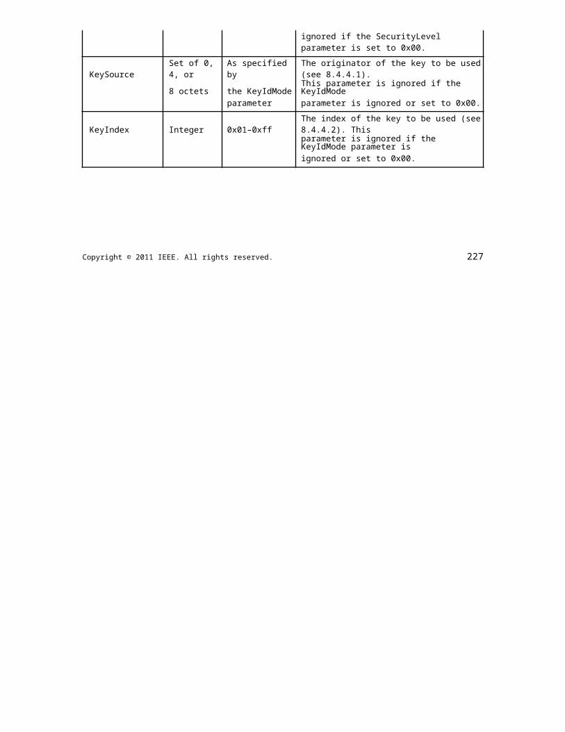
IEEE Std 802.15.7r1-20xx IEEE STANDARD FOR SHORT-RANGE WIRELESS
Figure 314—5-division pattern
Figure 315—N-division pattern (N = 6, 7, 8)
Figure 316—9-division pattern
458 Copyright © 20xx IEEE. All rights reserved.

OPTICAL COMMUNICATION IEEE Std 802.15.7r1-20xx
Figure 317—N-division pattern (N = 10 - 16)
Figure 3 - Packet division pattern of Packet PWM/PPM mode 2
The number of the second line of each box means bit size and the third line means bit value.
When transmitter transmit data of more than 112 bits or stream data, stop bit of packet 15 is 0, and the fol-lowing data is transmitted from packet 0.
This MAC frame does not have MHR field and the MFR field is optional as same as mode 1.
15.4.7 7.3 MAC frame format of Packet PWM/PPM mode 3
(TBD)
16. PHY C
16.1 2D-sequential color code
16.2 VTASC
The IEEE802.15.7r1 PHY 7r1_2 with supported data rates and operating conditions is shown in Table 1-1 for Visible Mode of data Transmission. The Display Light Pattern Based Transmitter with VTASC works with variable size pattern and different type patterns. The data embedded on visual frame by overlaying visual patterns displays visual area. The PHY system diagram in PHY 7r1_2 illustrated in Figure 2-1 for 7r1_2 - Multipoint Source for Display Light Pattern Based Transmitter with VTASC.
Copyright © 2011 IEEE. All rights reserved. 459
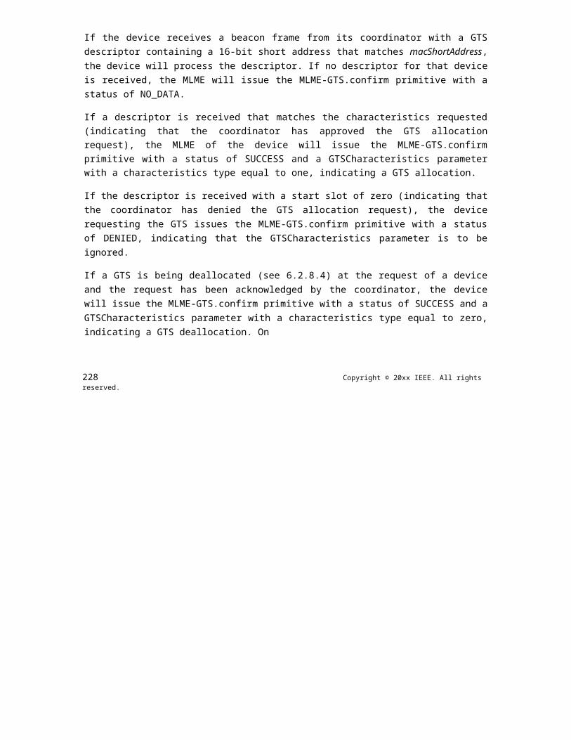
IEEE Std 802.15.7r1-20xx IEEE STANDARD FOR SHORT-RANGE WIRELESS
Figure 318—Display Light Pattern Based Transmitter with VTASC PHY System Diagram
The IEEE802.15.7r1 PHY 7r1_2 designed with specific key features in consideration to have error free and effective display to camera communication in the real-time usage of end system. The design goals are,
"Angle and Distance Free Communication
"Rx Distance Adaptive Communication by Screen with interactive Camera
"Asynchronous Communication
"Rx Frame Rate independent Transmission
"Multi-Display Model for Transmission
To achieve the above described design goal, The PHY is Uses Spread Spectrum based VTASC. The use cases of the modulation scheme and SS Modulation parameter are described in this section.
16.2.1 VTASC
Color Shift Keying (CSK) is one of the promising modulation formats specifically for Display based VLC system. In order to improve the distance and angle free with higher bitrate, the new proposed color based modulation scheme called Variable Transparent Amplitude-Shape-Color (VTASC) Modulation is proposed. VTASC is one of the promising modulation formats specifically for display based VLC system with improved VLC throughput by increasing the bit per symbol rate, and avoiding the single color interference.
The VTASC is coded by M (color) / N (amplitude) / Q (shape) / ? (transparency) State as described in the below;
460 Copyright © 20xx IEEE. All rights reserved.
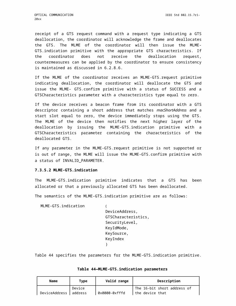
OPTICAL COMMUNICATION IEEE Std 802.15.7r1-20xx
Figure 319—VTASC coding
The no of coded Levels in the VTASC schemes (MxNxQx?): 256 = 28 and this makes place to code 8 bit Symbol with 8/4/4/2 Color/Amplitude/Shape/transparency). The coded sample model is given Figure 2-2.
Figure 320—VTASC Coded Pattern Model
The following Table 2-1 describes the Symbol Coding using VTASC schemes. The VTASC is able to expand a Domain size and add a transparency or blinking domain.
Table 2-1 - VTASC Symbol per Bit Mapping
Copyright © 2011 IEEE. All rights reserved. 461

IEEE Std 802.15.7r1-20xx IEEE STANDARD FOR SHORT-RANGE WIRELESS
Table 146—VTASC Symbol per Bit Mapping
VTASC MxNxQxa Bit
M=2, N=2, Q=2, a=2 16=244
M=2, N=2, Q=2, a=2 32=255
M=2, N=2, Q=2, a=2 64=266
M=2, N=2, Q=2, a=2 128=277
M=2, N=2, Q=2, a=2 256=288
16.2.2 Spread Spectrum
The Spread Spectrum adopted with PHY model design for Display Light Pattern Based Transmitter with VTASC to add built-in adaptation on data recovery and to achieve asynchronous communication with Angle free and distance free communication between Display Transmitter and Smartphone Receiver.
In proposed PHY model used Gold Sequence based Spreading code for encode data. The Study case of SS Code Sequence is follows,
"Spreading Code (Gold Sequence)
- Gold sequence was chosen as a spreading code
- Shifter register length is 5
- Code length is 31 (=25-1)
- 4 family code set was generated via offset 8*n chips of code set 1
- Code Sets
Code set 1: 0000000010010100100111101010110 (zero offset)
Code set 2: 1001010010011110101011000000000 (8chip offset)
Code set 3: 1001111010101100000000010010100 (16chip offset)
Code set 4: 1010110000000001001010010011110 (24chip offset)
The Figure 2-3 shows the SS Gold Sequence Generator model.
462 Copyright © 20xx IEEE. All rights reserved.
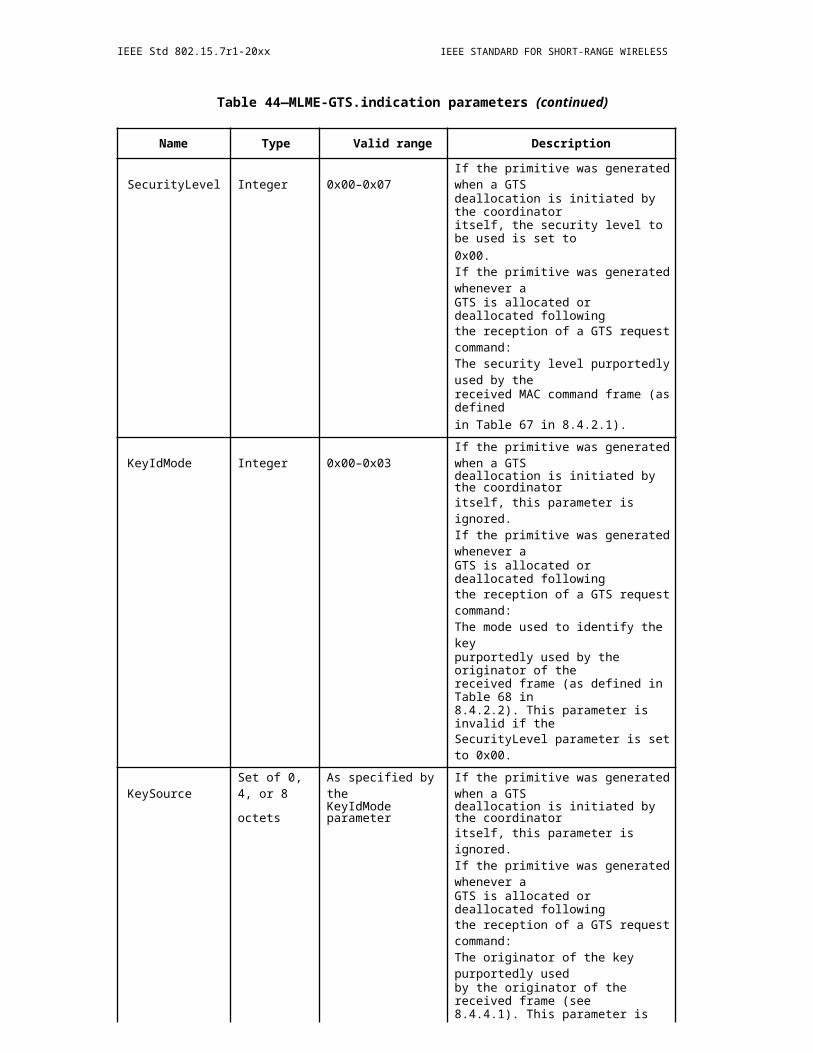
OPTICAL COMMUNICATION IEEE Std 802.15.7r1-20xx
Figure 321—Gold Sequence Generator
The Table 2-2 describes the SS Modulation Parameters adopted for simulating proposed PHY Layer design.
Table 2-2 - SS Modulation Parameters Study Case
Table 147—SS Modulation Parameters Study Case
Data Rate (bps)
Parameter 1000 2000 3000 Units Consideration
Tx data size 20 40 80 bits Payload size
Frame duration 20 20 20 ms
SS chip rate 2 2 2 Mcps Spreading chip rate
Spreading factor 8 4 2
Processing gain 8 4 2
Number of chips32 128 512 chipsper frame
Grid allocation 8*4 16*8 32*16The number of rows and columns of
screen
16.2.3 Data Encoder
The Display Light Pattern Based Transmitter with VTASC Schemes works with two data embedding method. The supported data embedding principles are Alpha Blending and Watermarking. The rule to embedding data and data rate achievement vary based on the kind of display used to design the Transmitter.
Copyright © 2011 IEEE. All rights reserved. 463

IEEE Std 802.15.7r1-20xx IEEE STANDARD FOR SHORT-RANGE WIRELESS
16.2.4 Asynchronous Communication Mode
The IEEE802.15.7r1 PHY for Display Light Pattern Based Transmitter with VTASC designed with Asyn-chronous communication mode. The Asynchronous communication achieved when transmitting data, differ-ent spreading code is used per video frame. Each code sets repeated for spreading data according to spreading factor and each spreading code set 1, 2, 3, and 4 are assigned for successive 4 frames as shown in Figure 2-4.
Figure 322—SS Code Assignment
The receiver side spreading code already known with application to synchronize the data automatically. If camera CMOS received same frame, for example #1 video frame receive twice, then receiver will despread video frames using SC#1, SC#2. When processing using SC#2, dominant value will not appear so the video frame will be discarded.
16.2.5 Angle Free Communication
The IEEE802.15.7r1 PHY for Display Light Pattern Based Transmitter with VTASC designed with Angle Free Communication between Transmitter and Receiver is shown in Figure 2-5. The Angle free communica-tion is achieved by synchronizing the spread code after decoding data. The automatic synchronization is time consuming feature but system functioning is robust.
Figure 2-5 - Angle Free and Distance Adaptive
464 Copyright © 20xx IEEE. All rights reserved.
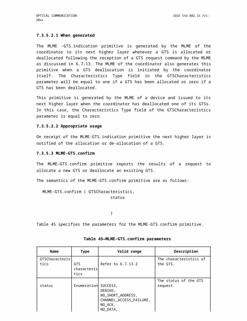
OPTICAL COMMUNICATION IEEE Std 802.15.7r1-20xx
Figure 324—Angle Free and Distance Adaptive
16.2.6 Scalable Bitrate Controller
The IEEE802.15.7r1 PHY for Display Light Pattern Based Transmitter with VTASC designed with built-in Scalable bitrate Controller. To achieve robust communication, the scalable data transmission mode is pro-posed in PHY model design is shown in Figure 2-6. The Screen is divided into Multiple regions and each region has different frame rate controlled data transmission is enabled. This approach adds robustness on system performance for Frame Rate Adaptive Transmission.
Figure 325—Scalable Bit Rate Controller
16.2.7 Distance Adaptive Data Rate Control
The IEEE802.15.7r1 PHY for Invisible Data Embedded Display TX Schemes designed with distance adap-tive data rate control. In this case the Transmitter built-in with camera features as shown in Figure 2-7. The Transmitter Camera Estimate the Receivers distance using camera. The sequence code length assignment is based the distance of the receiver from transmitter. If the receiver is near then the SF Value is small so Short Sequence Code is assigned otherwise SF values is high so Long Sequence Code is assigned. In this way, PHY model design control the distance adaptive data rate selection.
Copyright © 2011 IEEE. All rights reserved. 465

IEEE Std 802.15.7r1-20xx IEEE STANDARD FOR SHORT-RANGE WIRELESS
Figure 326—Distance Adaptive Data rate Control
16.3 Invisible data-embedding
16.4 PAPM
16.5 CSM (withdrawn)
Refer to the nominal CSM text in Clause 14.6.
466 Copyright © 20xx IEEE. All rights reserved.
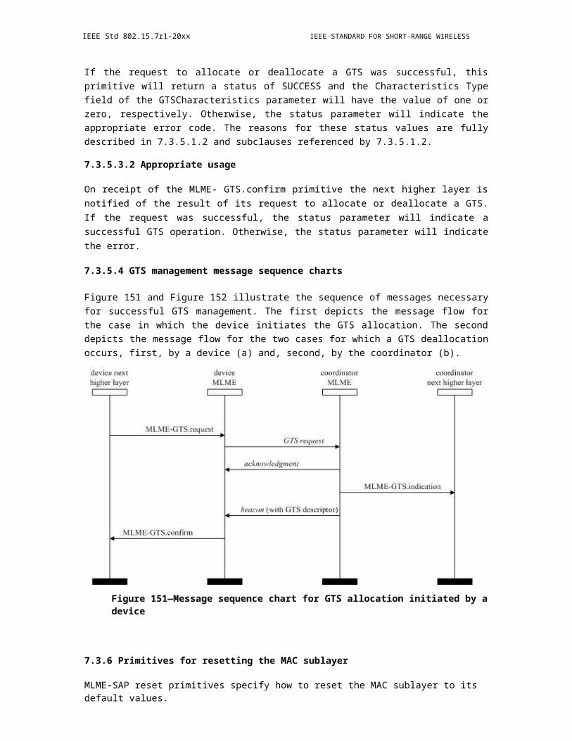
OPTICAL COMMUNICATION IEEE Std 802.15.7r1-20xx
16.6 Kookmin Invisible code (16/358r0)
THE INPUT WAS ONLY A FEW PAGES AND DUE TO TIGHT TIME CONSTRAINTS I PUT ALL THEINPUT INTO THIS ONE SECTION. THE MATERIAL NEEDS TO BE REDISTRIBUTED THROUGHOUTTHE DOCUMENT. - RICK
Table 148—2D-invisible sequential code
PHY Operating Modes
ModulationRLL Code
Optical ClockFEC
Data Rate (bits)
(m:n) Rate m x n x 15 x FEC_rate
2D-invisible sequen-None 30 Hz FEC option 180 x FEC_ratetial code 4:3
2D-invisible sequen-None 30 Hz FEC option 2400 x FEC_ratetial code 16:10
2D-invisible sequen-None 30 Hz FEC option 600 x FEC_ratetial code 8:5
2D-invisible sequen-None 30 Hz FEC option 2160 x FEC_ratetial code 16:9
2D-invisible sequen-None 30 Hz FEC option 360 x FEC_ratetial code 8:3
N: Number of vertical cells
M: Number of horizontal cells
FEC_option: Select one FEC scheme from Table
1 FEC_rate: the data rate scale of FEC scheme
Figure 1 shows an example of cell configuration on display device with M=4 and N=3.
Figure 327—Example of cell construction
Copyright © 2011 IEEE. All rights reserved. 467
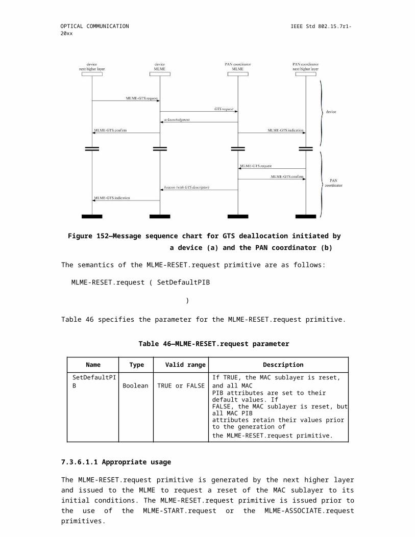
IEEE Std 802.15.7r1-20xx IEEE STANDARD FOR SHORT-RANGE WIRELESS
Table 149—FEC option
FEC option FEC description FEC rate
1 none 1
2 RS(64,32) 1/2
3 RS(160,128) 128/160
4 RS(15,7) 5/7
5 RS(15,11) 11/15
6 RS(15,2) 2/15
7 RS(15,4) 4/15
8 RS(15,7) 7/15
9 CC(1/4) 1/4
10 CC(1/3) 1/3
11 CC(2/3) 2/3
16.6.1 PHY specifications
16.6.2 Reference modulator diagram
The reference implementation diagram is in Figure 2.
Figure 328—Reference modulation diagram
The image framing order for n x m bits data encoding is shown in Figure 3.
468Copyright © 20xx IEEE. All rights reserved.

OPTICAL COMMUNICATION IEEE Std 802.15.7r1-20xx
Figure 329—Image frame order
16.6.3 Invisible sequential code Encoder
The encoded bits in display cell are defined as:
Logic zero: represented by the unchanged sensitive element of color space.
Logic one: represented by the changed sensitive element of color space.
An example of logic bit encoding is shown in Figure 4.
Figure 330—Example of modulated image frame with 110001000010 bits stream. (a. Refer-ence image. b. Modulated image)
16.6.4 PHY Layer Dimming Method (move to clause 9.5)
Invisible sequential code can support dimming by changing the brightness of display image. The brightness does not affect the invisible element of reference image and embedded image. The reference diagram is shown by Figure 5.
Copyright © 2011 IEEE. All rights reserved. 469
IEEE Std 802.15.7r1-20xx IEEE STANDARD FOR SHORT-RANGE WIRELESS
Figure 331—Reference modulator diagram with dimming control data
16.6.5 PPDU format (move to clause 9.6)
The PPDU frame structure shall be formatted as illustrated in Figure 6.
Figure 332—Format of the PPDU
16.6.6 Preamble Field
The synchronization of one superframe data based on 2 mark image frames as Figure 7. Length of preamble field varies from 24 to 380 bits. It depends on the operation mode.
470 Copyright © 20xx IEEE. All rights reserved.
OPTICAL COMMUNICATION IEEE Std 802.15.7r1-20xx
Figure 333—Preamble frame
16.6.7 PHY header
The PHY header, as shown in Table 2, defines the data length of data payload.
Table 2.
Table 150—
PHY header fields Bit-width Explanation on usage
PSDU length 8 Length up to aMaxPHYFrameSize
FEC option 8 Provide information about FEC option
16.6.8 PSDU field (move to clause 9.6)
The PSDU field has a variable length and carries the data of the PHY frame.
16.6.9 PHY PIB attributes (move to clause 10.5)
16.6.10 Superframe Structure (move to clause 6.1)
Invisible sequential code is applied for broadcasting mode. There is no access control mechanism. There is no superframe.
Copyright © 2011 IEEE. All rights reserved. 471
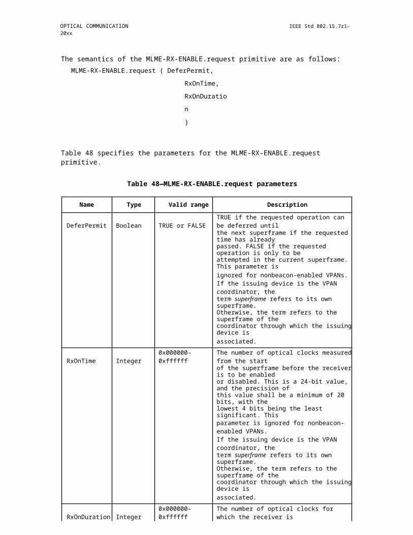
IEEE Std 802.15.7r1-20xx IEEE STANDARD FOR SHORT-RANGE WIRELESS
16.6.11 MAC frame formats (move to clause 6.4)
The MAC frame contains only frame Payload. The length of frame Payload is defined by PSDU length value of PHY header.
16.6.12 MAC PIB attributes (move to clause 7.5)
16.7 Invisible Data embedded display Tx Schemes (16/354r0)
16.7.1 PHY Layer Operating Mode(s) (move to clause 9.1)
The IEEE802.15.7r1 OWC TG ISC/L-PD PHY mode classification for Draft Document D0 is introducing the following three new PHY modes.
"PHY A - Discrete (or Singular) Source
"PHY B - Surface Source
"PHY C - 2-Dimensional / Screen Source
The SNUST Invisible Data Embedded Display TX Schemes for OCC uses the PHY C - 2 Dimensional / Screen Source. For the opted PHY operation mode, the modulation scheme may not require any dimming control for SNUST proposed 2 Dimensional / Screen Sources.
The IEEE802.15.7r1 PHY C Operating Modes system specifications are given in Table 1-1.
PHY C Operating Modes
Insert Table 1-1 - IEEE802.15.7r1 PHY Operating Mode for Invisible Data Embedded Display TX Schemes
16.7.2 PHY Specifications
The IEEE802.15.7r1 PHY C with supported data rates and operating conditions is shown in Table 1-1 for Visible Mode of data Transmission. The Invisible Data Embedded Display TX Schemes works with two data embedding method. The supported data embedding principles are Alpha Blending and Watermarking. The PHY system diagram in PHY VI illustrated in Figure 2-1 for PHY C - 2 Dimensional / Screen Source for Invisible Data Embedded Display TX Schemes for OCC.
472 Copyright © 20xx IEEE. All rights reserved.
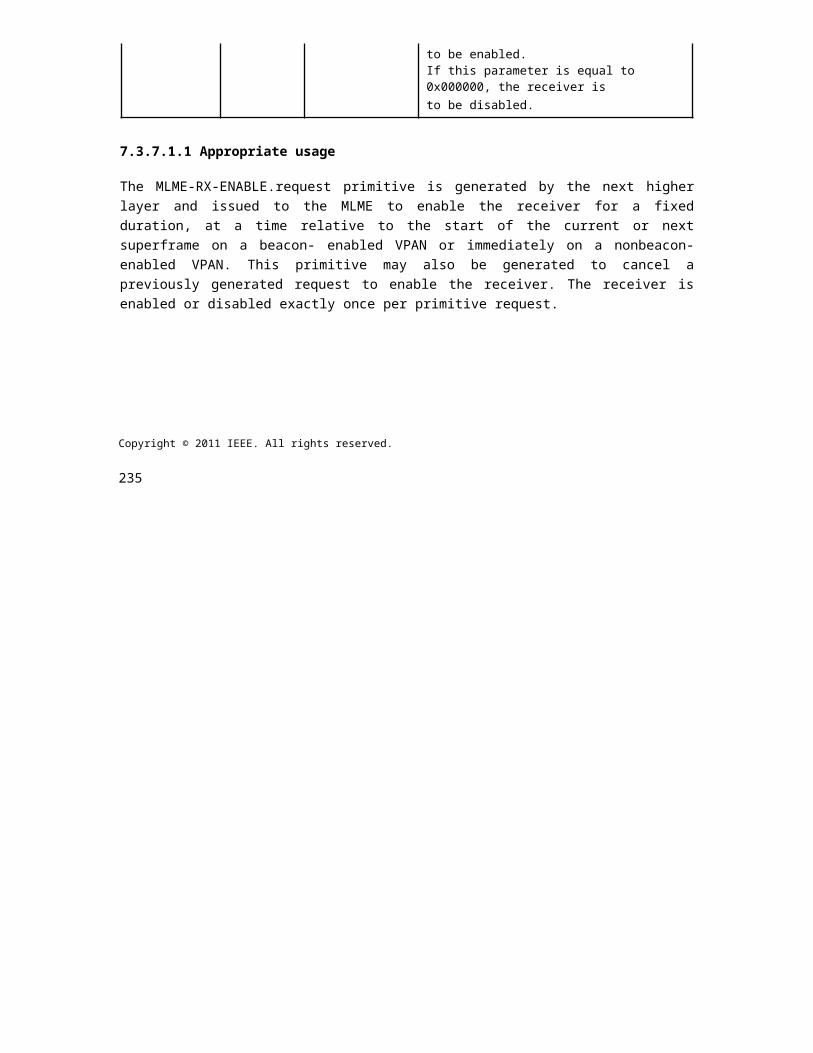
OPTICAL COMMUNICATION IEEE Std 802.15.7r1-20xx
Figure 334—Invisible Data Embedded Display TX Schemes PHY System Diagram
The IEEE802.15.7r1 PHY C designed with specific key features in consideration to have error free and effective display to camera communication in the real-time usage of end system. The design goals are,
"Unobtrusive to Screen Viewer
"Works on dynamic visual Scene
"Angle and Distance Free Communication
"Rx Distance Adaptive Communication by Screen with interactive Camera
"Asynchronous Communication
"Rx Frame Rate independent Transmission
"Multi-Display Model for Transmission
To achieve the above described design goal, The PHY is Uses Spread Spectrum based M-PSK, M -FSK, Hybrid -M-PSK-FSK, Sequential Scalable 2D Codes. The use cases of the modulation scheme and SS Mod-ulation parameter are described in this section.
16.7.3 Modulation Schemes
Use Case of Modulation Scheme 1 - M-PSK:
The Figure 2-2 describes the M-PSK modulation scheme usage on PHY Layer design.
Figure 335—M-PSK Modulation
Copyright © 2011 IEEE. All rights reserved. 473

IEEE Std 802.15.7r1-20xx IEEE STANDARD FOR SHORT-RANGE WIRELESS
Use Case of Modulation Scheme 2 - M-FSK:
The Figure 2-3 describes the M-FSK modulation scheme usage on PHY Layer design.
Figure 336—M-FSK Modulation
Use Case of Modulation Scheme 3 - Hybrid (M-PSK-FSK)
Hybrid scheme used to achieve double the data rate of M-PSK or F-FSK by combining Frequency and Phase on the modulation. The Figure 2-4 describes the Hybrid modulation scheme usage on PHY Layer design.
Figure 337—Hybrid (M-PSK-FSK) Modulation
Use Case of Modulation Scheme 4 - Sequential Scalable 2D Codes
The Sequential Scalable 2D codes used the QR Code and Color Code to encode the data with visual frame on display. The Sample 2D codes are shown in Figure 2-5.
474 Copyright © 20xx IEEE. All rights reserved.

OPTICAL COMMUNICATION IEEE Std 802.15.7r1-20xx
Figure 338—2D Codes
The proposed Sequential Scalable 2D Codes for IEEE802.15.7r1 PHY VI system design to enable distance adaptive data rate control on TX Schemes for OCC.
The use case for Sequential Scalable QR code is shown in Figure 2-6.
Figure 339—Sequential Scalable QR Code
The use case for Sequential Scalable Color code is shown in Figure 2-7.
Figure 340—Sequential Scalable Color Code
16.7.4 Spread Spectrum
The Spread Spectrum adopted with PHY design for Invisible Data Embedded Display TX Schemes to add built-in adaptation on data recovery and to achieve asynchronous communication with receiver angle free and distance adaptive communication between Display Transmitter and Smartphone Receiver.
Copyright © 2011 IEEE. All rights reserved. 475
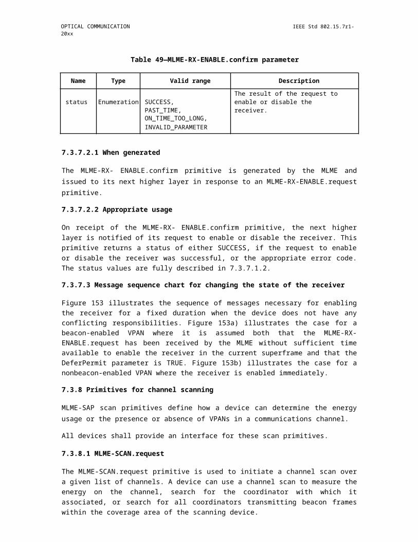
IEEE Std 802.15.7r1-20xx IEEE STANDARD FOR SHORT-RANGE WIRELESS
In this PHY model used Gold Sequence based Spreading code for encode data. The Study case of SS Code Sequence is follows,
"Spreading Code (Gold Sequence)
- Gold sequence was chosen as a spreading code
- Shifter register length is 5
- Code length is 31 (=25-1)
- 4 family code set was generated via offset 8*n chips of code set 1
- Code Sets
Code set 1: 0000000010010100100111101010110 (zero offset)
Code set 2: 1001010010011110101011000000000 (8chip offset)
Code set 3: 1001111010101100000000010010100 (16chip offset)
Code set 4: 1010110000000001001010010011110 (24chip offset)
The Figure 2-8 shows the SS Gold Sequence Generator model.
Figure 341—Gold Sequence Generator
The Table 2-1 describes the SS Modulation Parameters adopted for simulating proposed PHY Layer design.
Insert Table 2-1 - SS Modulation Parameters Study Case
16.7.5 Data Encoder
The Invisible Data Embedded Display TX Schemes works with two data embedding method. The supported data embedding principles are Alpha Blending and Watermarking. The rule to embedding data and data rate achievement vary based on the kind of display used to design the Transmitter.
476 Copyright © 20xx IEEE. All rights reserved.

OPTICAL COMMUNICATION IEEE Std 802.15.7r1-20xx
16.7.6 Asynchronous Communication Mode
The IEEE802.15.7r1 PHY for Invisible Data Embedded Display TX Schemes designed with Asynchronous communication mode. The Asynchronous communication achieved when transmitting data, different spreading code is used per video frame. Each code sets repeated for spreading data according to spreading factor and each spreading code set 1, 2, 3, and 4 are assigned for successive 4 frames as shown in Figure 2-9.
Figure 342—SS Code Assignment
The receiver side spreading code already known with application to synchronize the data automatically. If camera CMOS received same frame, for example #1 video frame receive twice, then receiver will despread video frames using SC#1, SC#2. When processing using SC#2, dominant value will not appear so the video frame will be discarded.
16.7.7 Angle Free Communication
The IEEE802.15.7r1 PHY for Invisible Data Embedded Display TX Schemes designed with Angle Free Communication between Transmitter and Receiver. The Angle free communication is achieved by synchro-nizing the spread code after decoding data. The automatic synchronization is time consuming feature but system functioning is robust.
16.7.8 Scalable Bitrate Controller
The IEEE802.15.7r1 PHY for Invisible Data Embedded Display TX Schemes designed with built-in Scal-able bitrate Controller. To achieve robust communication, the scalable data transmission mode is proposed in PHY model design is shown in Figure 2-10. The Screen is divided into Multiple regions and each region has different frame rate controlled data transmission is enabled. This approach adds robustness on system performance for Frame Rate Adaptive Transmission.
Figure 343—Scalable Bitrate Controller
Copyright © 2011 IEEE. All rights reserved. 477

IEEE Std 802.15.7r1-20xx IEEE STANDARD FOR SHORT-RANGE WIRELESS
16.7.9 Distance Adaptive Data Rate Control
The IEEE802.15.7r1 PHY for Invisible Data Embedded Display TX Schemes designed with distance adap-tive data rate control. In this case the Transmitter built-in with camera features as shown in Figure 2.11. The Transmitter Camera Estimate the Receivers distance using camera. The sequence code length assignment is based the distance of the receiver from transmitter. If the receiver is near then the SF Value is small so Short Sequence Code is assigned otherwise SF values is high so Long Sequence Code is assigned. In this way, pro-posed PHY model control the distance adaptive data rate selection.
Figure 344—Distance Adaptive Data rate Control
16.7.10 PHY Layer Dimming Method (move to clause 9.5)
The Display to camera communication dimming control is depending on the mode of embedding data (Visi-ble or Invisible) on display system, rate at which data is repeatedly coding on video frame, and rate at which data refresh on display.
The IEEE802.15.7r1 Invisible Data Embedded Display TX Schemes for OCC uses the Alpha Blending or Watermarking to embed the data on Video display frame. The function description of proposed PHY model is given in Figure 3-1.
Figure 345—Display Transmitter Functional Block Diagram
The Smart Device Camera Capture Visual Frame from Screen is shown Figure 3-2.
478 Copyright © 20xx IEEE. All rights reserved.

OPTICAL COMMUNICATION IEEE Std 802.15.7r1-20xx
Figure 346—Smartphone Receiver Functional Block Diagram
The ROI of Screen Visual Area is extracted from the captured visual frame and then apply the Sequential Scalable 2D Code or M-FSK or M-QPSK detector based on mapping scheme applied. The data recovered by applying SS on the data decoded.
The IEEE802.15.7r1 PHY for Invisible Data Embedded Display TX Schemes designed with built -in Scal-able bitrate Controller by controlling the Video display refresh rate or by frames in which data to be encoded repeatedly.
16.7.11 PPDU Format (move to clause 9.6)
The PPDU frame structure presented in IEEE802.15.7-2011 (Figure 118 - Format of the PPDU) is shown in Figure 4-1.
Figure 347—Format of the IEEE802.15.7-2011 PPDU
The IEEE802.15.7r1 PPDU frame structure is formatted as illustrated in Figure 4-2 for PHY- C - 2 Dimen-sional / Screen Source
Copyright © 2011 IEEE. All rights reserved. 479
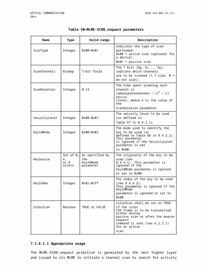
IEEE Std 802.15.7r1-20xx IEEE STANDARD FOR SHORT-RANGE WIRELESS
Figure 348—Format of the IEEE802.15.7r1 PPDU
SHR Field:
The SHR field is used by the transceiver to obtain optical clock synchronization with an incoming message is called Preamble. The standard defines one fast locking pattern (FLP) followed by choice of four topology dependent patterns (TDPs) for the purposes of distinguishing different PHY topologies is shown in Table 4-1.
Insert Table 4-1 - Preamble Pattern with Topologies
PHR Field:
The IEEE802.15.7r1 PHY header is described as shown in Table 4-2 and shall be transmitted with data to identify the PHY Mode, Data rate, and PSDU length to identify the transmission specification.
Insert Table 4-2 - PHY Header
Burst Mode Field: The burst mode bit indicates that the next frame following the current frame is part of the burst mode.
Channel Number Field: The channel number field for PHY shall be the band plan ID of the lowest wave-length.
MCS ID Field: The modulation and coding scheme (MCS) ID shall be indicated in the PHY header based on Table 83.
PSDU Field: The PSDU length field specifies the total number of octets contained in the PSDU.
PSDU Field:
The PSDU field has a variable length and carries the data of the IEEE802.15.7r1 PHY frame. The FCS is appended if the PSDU has a non-zero byte payload. The structure of the PSDU field is as shown in Figure 4-3.
480 Copyright © 20xx IEEE. All rights reserved.
OPTICAL COMMUNICATION IEEE Std 802.15.7r1-20xx
Figure 349—IEEE802.15.7r1 PHY PSDU Field Structure
16.7.12 PHY PIB Attributes (move to clause 10.5)
The PHY PIB comprises the attributes required to manage the PHY sublayer of a device. The attributes con-tained in the IEEE802.15.7-2011 PHY PIB are presented in Table 100 - PHY PIB Attributes.
The additional PHY PIB attributes added on IEEE802.15.7r1 for 2 Dimensional codes is presented the Table 5-1.
Table 151—IEEE802.15.7r1 PHY PIB Attributes Additions
Attribute Identifier Type Range Description
This attribute specifies theapplication specific PHYmode.
phyINVApplication- 0 : Normal Data (Media
0x10 Unsigned 0~255 Content, Information Con-SpecificMode tent based on the Applica-
tion used for)1 : ID Data2 : Authentication Data
16.7.13 Superframe Structure (move to clause 6.1)
The Super frame structure presented in IEEE802.15.7-2011 is shown in Figure 6-1
Copyright © 2011 IEEE. All rights reserved. 481
IEEE Std 802.15.7r1-20xx IEEE STANDARD FOR SHORT-RANGE WIRELESS
Figure 350—Superframe Structure
The Invisible Data Embedded Display TX Schemes use unslotted ALOHA; that is, when the Invisible Data Embedded Display transmitter has a packet to send, it just sends it. This support with beacon and without beacon support and the transmitter does not do a listen before talk channel activity check.
The super frame structure for IEEE802.15.7r1 without beacon is shown in Figure 6-2.
Figure 351—IEEE802.15.7r1 Superframe Structure without Beacon
The super frame structure for IEEE802.15.7r1 with beacon is shown in Figure 6-3.
Figure 352—IEEE802.15.7r1 Superframe Structure with Beacon
482 Copyright © 20xx IEEE. All rights reserved.
OPTICAL COMMUNICATION IEEE Std 802.15.7r1-20xx
16.7.14 MAC Frame Formats (move to clause 6.4)
The MAC frame structure presented in IEEE802.15.7-2011 (Figure 44 - General MAC Frame Format) is shown in Figure 7-1.
Figure 353—General MAC Frame Format
The IEEE802.15.7r1 MAC frame structure is formatted as illustrated in Figure 7-2 for 2 Dimensional codes.
Figure 354—IEEE802.15.7r1 MAC Frame Format
Frame Control Field:
The frame control field presented in IEEE802.15.7-2011 (Figure 45 - Format of the Frame Control Field) is shown in Figure 7-3.
Copyright © 2011 IEEE. All rights reserved. 483

IEEE Std 802.15.7r1-20xx IEEE STANDARD FOR SHORT-RANGE WIRELESS
Figure 355—IEEE802.15.7 Frame Control Field Format
The IEEE802.15.7r1 frame control field is formatted as illustrated in Figure 7-4 for 2 Dimensional codes.
Figure 356—IEEE802.15.7r1 Frame Control Field Format
Frame Version Subfield: Specifies the version number corresponding to the frame. This subfield shall be set to 0b01 to indicate a frame compatible with IEEE Standard 802.15.7r1. And all other subfield values shall be reserved for future use.
Frame Type Subfield: Specifies the Frame Type used in MAC Frame. This field shall be set to one of the non-reserved values listed in Table 7-1.
Insert Table 7- 1 - IEEE802.15.7r1 Frame Type Subfield
Security Enabled Subfield: Species the Security on Data Frame is enable or not on transmission. This field is 1 bit in length, and it shall be set to one if the frame is protected by the MAC sublayer and shall be set to zero otherwise. The Auxiliary Security Header field of the MHR shall be present only if the Security Enabled subfield is set to one.
Frame Pending Subfield: Species the Pending on Data Frame is available or not on transmission. This field is 1 bit in length and shall be set to one if the device sending the frame has more data for the recipient. This subfield shall be set to zero otherwise.
Acknowledgment Request Subfield: Specifies whether an acknowledgment is required from the recipient device on receipt of a data or MAC command frame. This field is 1 bit in length and this subfield is set to one, the recipient device shall send an acknowledgment frame. If this subfield is set to zero, the recipient device shall not send an acknowledgment frame.
484 Copyright © 20xx IEEE. All rights reserved.
OPTICAL COMMUNICATION IEEE Std 802.15.7r1-20xx
Sequence Number Field:
The Sequence Number field is 1 octet in length and specifies the sequence identifier for the frame.
For a beacon frame, the Sequence Number field shall specify a BSN. For a data, acknowledgment, or MAC command frame, the Sequence Number field shall specify a DSN that is used to match an acknowledgment frame to the data or MAC command frame.
Destination Address Field:
The Destination Address field, when present, is either 2 octets or 8 octets in length, according to the value specified in the Destination Addressing Mode subfield of the frame control field, and specifies the address of the intended recipient of the frame.
A 16-bit value of 0xffff in this field shall represent the broadcast short address, which shall be accepted as a valid 16-bit short address by all devices currently listening to the channel.
This field shall be included in the MAC frame only if the Destination Addressing Mode subfield of the frame control field is nonzero.
Source Address Field:
The Source Address field, when present, is either 2 octets or 8 octets in length, according to the value spec-ified in the Source Addressing Mode subfield of the frame control field, , and specifies the address of the originator of the frame.
This field shall be included in the MAC frame only if the Source Addressing Mode subfield of the frame control field is 10 or 11.
Frame Payload Field:
The Frame Payload field has a variable length and contains information specific to individual frame types. If the Security Enabled subfield is set to one in the frame control field, the frame payload is protected as defined by the security suite selected for that frame.
FCS Field:
The FCS field is 2 octets in length and the FCS is calculated over the MHR and MSDU parts of the frame. The FCS shall be only generated for payloads greater than zero bytes.
The FCS is option is given as an optional option, it is adaptive to RS/CRC/NONE.?
16.7.15 MAC Frame Formats (move to clause 6.4)
The MAC PIB comprises the attributes required to manage the MAC sublayer of a device. The attributes contained in the IEEE802.15.7-2011 MAC PIB are presented in Table 60 - MAC PIB Attributes. The addi-tional MAC PIB attributes added on IEEE802.15.7r1 for 2 Dimensional codes is presented the Table 8-1.
Insert Table 8-1 - IEEE802.15.7r1 MAC PIB Attributes Additions
Copyright © 2011 IEEE. All rights reserved. 485
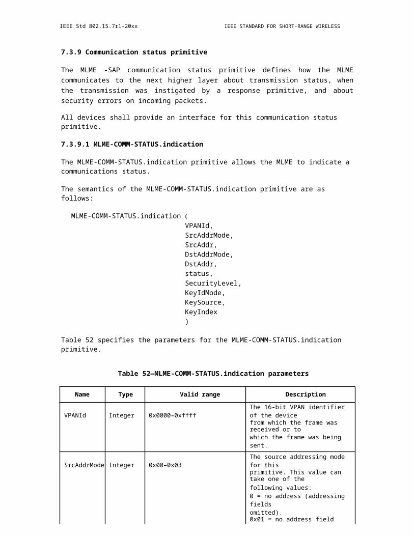
IEEE Std 802.15.7r1-20xx IEEE STANDARD FOR SHORT-RANGE WIRELESS
17. PHY VII
17.1 Fraunhofer High-bandwidth PHY (ref. 16/356r0)
Table 152—PHY Operating Modes (move to cluase 9.1)
PHY Operating Modes
modulation DC-biased DMT
subcarrier spacing 195.3125 KHz
cyclic prefix (CP) 160, 320 ns
symbol duration (w/o CP) 5.12 us
FEC Low-density parity-check code (LDPC)
information block size 120, 540 bytes
code rates 1/2, 2/3, 5/6, 16/18, 20/21
repetitions 1, 2, 3, 4, 6, 8
Optical Clock Rate Used Carriers Min. to Max. DataBandwidth (IFFT size using(Factor) RateDMT)
10 MHz 25 MS/s (1/8) 45 (128) 1.5 to 103 Mb/s
25 MHz 50 MS/s (1/4) 107 (256) 3 to 257 Mb/s
50 MHz 100 MS/s (1/2) 215 (512) 7 to 512 Mb/s
100 MHz 200 MS/s (1/1) 450 (1024) 14 to 1028 Mb/s
200 MHz 400 MS/s (2/1) 950 (2048) 35 to 2056 Mb/s
500 MHz 1 GS/s (5/1) 2375 (2x2048) 87 to 5140 Mb/s
1 GHz 2 GS/s (100/1) 4750 (3x2048) 145 to 10281 Mb/s
486 Copyright © 20xx IEEE. All rights reserved.

OPTICAL COMMUNICATION IEEE Std 802.15.7r1-20xx
17.1.1 Introduction (move to clause 4)
The high-bandwidth PHY extends the capabilities and improves the transmission performance in order to address the specific requirements of new use cases in scenarios B1-B4 mentioned in the Technical Consider-ations Document (TCD) for 802.15.7r1 [8], such as optical wireless access in indoor/home/office, industrial wireless (with specific requirements for robustness, low latency and secure data transmission), communica-tions between vehicles and vehicle-to-the-roadside-infrastructure communications, and as a wireless back-haul technology.
17.1.1.1 Scope (???)
The high-bandwidth PHY supports fixed wireless links and multiple mobile user links via an OWC infra-structure, which consists of one or more optical wireless access points. The PHY is wavelength-agnostic and extends the optical wavelength range beyond the scope of 802.15.7 standard for visible light communication (VLC) also below and above the wavelengths of 380 nm and 780 nm, respectively hereby including the invisible light. A wide range of data rates (i.e., 1 Mb/s to 10 Gb/s) are supported, targeting an efficient use of the optical bandwidth also under time-variant channel conditions.
The high-bandwidth PHY introduces modern wireless transmission technologies, such as orthogonal fre-quency-division multiplexing (OFDM), adaptive transmission, multiple-input multiple-output (MIMO) and coordinated wireless networking of multiple access points (APs) to provide mobility for mobile user devices (UDs) in an OWC network infrastructure. In addition, specific requirements for enhanced robustness and lower latency are addressed to support e.g. industrial wireless, vehicular and backhaul scenarios (B2, B3, B4).
For coordinated networking, unified interfaces are introduced for the user plane and an open interface to the control plane, which can be used at the network layer to manage the interference between parallel optical wireless links and to support user mobility. These interfaces enable also the coexistence of OWC with radio based wireless links.
17.1.1.2 Network topologies (move to clause 4)
Figure 357—New network topologies coordinated wireless (COW) and wireless relaying (WREL)
The high-bandwidth PHY supports three new topologies, i.e. coordinated wireless (COW), heterogeneous network (HET) and relaying (WREL), as shown in Figure 3 1 and Figure 3 2 in addition to the point-to-point (P2P), broadcast (BC) and star (S) topologies already described in 802.15.7-2011. In COW topology, mobil-ity among multiple access points (APs), i.e. handover and interference coordination is supported. In the HET topology, optical wireless and radio frequency (RF) transmissions can be combined. In the WREL topology, the high-bandwidth PHY supports data transport including intermediate relays.
Copyright © 2011 IEEE. All rights reserved. 487
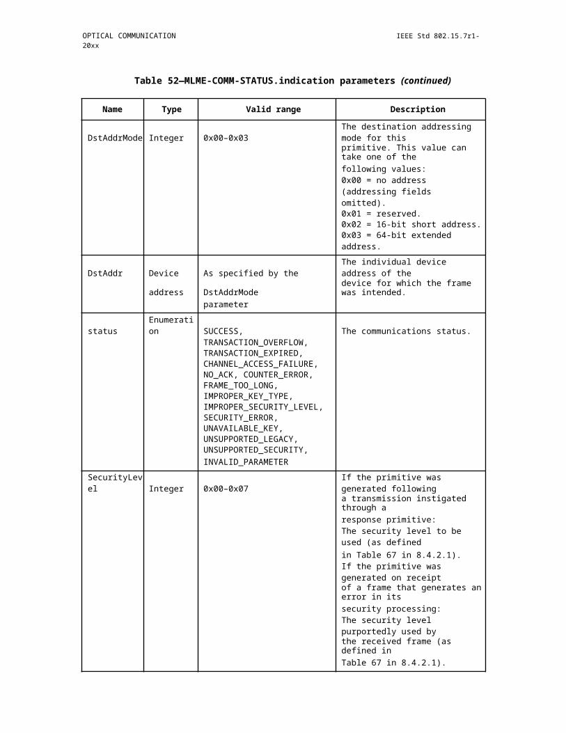
IEEE Std 802.15.7r1-20xx IEEE STANDARD FOR SHORT-RANGE WIRELESS
The high-bandwidth PHY defines all methods at the PHY layer for operating the link in P2P, S, COW, HET and WREL topologies. It is defined by higher layers (above the PHY) in which topology the link is operated. The PHY supports the respective data transport and control signaling needed in the respective topology.
17.1.1.2.1 Point-to-point
In the P2P topology, two UDs can connect to each other and establish a wireless link. The P2P link is defined such that it may serve as a wireless replacement of an Ethernet cable in any computer or telecommu-nication networks. Besides specifying the fundamental PHY architecture for all topologies, the MAC layer is assumed to support an automatic link setup and a feedback path for closed-loop frequency-selective link adaptation.
17.1.1.2.2 Star
In the S topology, one UD acts as AP serving multiple other UDs in parallel. The AP aggregates the traffic from multiple UDs and coordinates their wireless transmission. The S topology requires additional function-alities. The PHY supports time-division multiple access (TDMA) and frequency-division multiple access (FDMA). Feedback from UDs is transmitted in an orthogonal manner via the PHY, i.e., contention-free. An additional control channel is broadcast via the PHY to all UDs containing information about granted trans-mission resources for uplink and downlink directions.
17.1.1.2.3 Coordinated wireless network
In the COW topology, multiple UDs are served by multiple APs, which are in turn coordinated by a network controller (NC). The NC is a device that has a fixed network link to the APs. The NC reroutes the traffic paths between NC and APs in case of handover and controls the transmission of all APs and UDs to manage interference. APs are time-synchronized, what can be achieved e.g. by the IEEE 1588 precision time proto-col (PTP). The NC aggregates the wireless traffic of UDs and APs. However, its functionality is not part of 802.15.7r1. Only the specific data transport and control signaling needed in the COW topology are defined. Based on cell-specific reference signal, UDs and APs estimate the interference channel in down - and uplink directions, respectively. The corresponding metrics reports are conveyed in the downlink over the wireless uplink and via the APs to the NC and ii) in the uplink via the APs to the NC where it is used for interference coordination and handover.
17.1.1.2.4 Heterogeneous network
In the HET topology, there are 3 types of devices based on its capability of support OWC and RF. Table 4 1 shows the 3 different types of devices.
Insert Table 4 1 Device types here
Type 1 devices only have OWC transceivers, therefore only VLC links are available. Type 2 and type 3 devices have both OWC transceivers and RF transceivers and both OWC links and RF links are available. Therefore a heterogeneous network comprised of both OWC links and RF links can be formed as sown in Figure 3 2. Coordinators, which are LED lamps, are located at the room ceiling. Each coordinator is con-nected to the global controller through the backhaul link. The backhaul link is probably based on wired link, e.g., power line link. The global controller distributes downlink traffic to different coordinators and manages handover and interference coordination between different VPANs. Each coordinator provides OWC access to one or multiple devices. Type 2 and type 3 devices are connected to the global controller through RF links. The RF access point (AP) can be co-located at the global controller.
In the downlink direction, joint transmission through both OWC link and RF link and handover between OWC link and RF link are possible for both type 2 and type 3 devices. For type 2 devices, uplink traffic shall be transmitted through RF link and OWC command frames and ACK frames that need to be transmitted to
488 Copyright © 20xx IEEE. All rights reserved.

OPTICAL COMMUNICATION IEEE Std 802.15.7r1-20xx
the coordinator shall be first transmitted to the global controller through RF link and then forwarded to the coordinator through the backhaul link.
Figure 358—Heterogeneous network comprising of both RF links and VLC links
A heterogeneous network can have devices of all the three types. The global controller and coordinators shall distribute traffic and transmission opportunities to devices based on their capabilities of support RF and OWC.
17.1.1.2.5 Wireless relaying
In the REL topology, an intermediate relay device (RD) is enabled to assist a transmission via a direct opti-cal wireless link which may be shaded or blocked or in a bad signal condition. Both, classical relaying as well as cooperative relaying are supported. In this topology, it is assumed that each RD has multiple capabil-ities including duplexing and relay modes. For duplexing mode, the RF supports either full duplex (FD), where the RF receives and transmits data simultaneously, while in half duplex (HD), the RF receives the data in one time slots and retransmits the data in another time slot. For the relaying mode, the RD supports two modes; amplify-and-forward (AF), and decode-and-forward (DF) modes. In AF mode, the RD receives the data from the AP, which are then retransmitted after amplification to mitigate the channel degradation occurred during transmission from AP to RD. In DF mode, the data received by the RD is fully decoded and then retransmitted from the RD to the UD. In case the link between the AP and UD is disconnected, the AP will initiate a RD search request. Each The AP broadcasts a search RD request frame. Each RD replies back on the control channel with its own capabilities including duplexing and relaying modes. The AP selects the RD that provides the best performance according to a specific criterion. The AP initiates a relay setup link procedure between the AP, selected REL and the UD. A connection remains active until the direct link between the AP and UD is reinitiated and the AP requires a termination of the link between the AP and REL.
17.1.1.3 Essential Features (???)
17.1.1.3.1 Use cases
The high-bandwidth PHY supports all use cases B1-B4 and all light sources described in [8].
17.1.1.3.2 Transfer mode
The high-bandwidth PHY supports bidirectional, continuous and packet-based OWC.
17.1.1.3.3 Scalable data rates
The high-bandwidth PHY supports variable data rates from 1 Mbit/s to 10 Gbit/s by means of a scalable design. In all PHY modes, subcarrier spacing and cyclic prefix (CP) are the same. Used bandwidth is scal-able by adapting number of used subcarriers. Interoperability among all PHY modes is enabled, i.e. a trans-
Copyright © 2011 IEEE. All rights reserved. 489
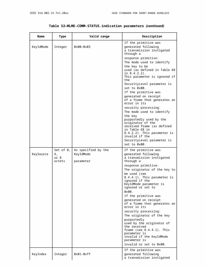
IEEE Std 802.15.7r1-20xx IEEE STANDARD FOR SHORT-RANGE WIRELESS
ceiver with a smaller bandwidth can synchronize with respect to, and exchange control information and data with, another transceiver having a higher bandwidth and vice versa. Bandwidth adaptation is supported to operate the link at the lowest bandwidth during link setup, and uses subcarriers at low frequencies only to transmit control information, before switching eventually to a higher bandwidth mode.
17.1.1.3.4 Waveform
An adaptive, real-valued OFDM waveform denoted as DC-biased discrete multi-tone (DMT) is used. It can be extended by an optional preprocessing in order to improve energy efficiency. Moreover, adaptive bit- and power loading is supported using variable modulation formats on each subcarrier or on groups of subcarri-ers, depending on the channel-, interference- and noise-characteristics of the optical wireless link.
17.1.1.3.5 Efficient use of the optical bandwidth
The high-bandwidth PHY supports the efficient use of the optical bandwidth by means of a highly scalable PHY layer design, together with closed-loop adaptive transmission and the efficient support of MIMO, cooperative transmission and relaying. This combination allows robustness in the multi-path propagation channel, in case of mobility and in interference scenarios. Moreover, PHY is defined so that one-way laten-cies of 1 ms are achievable.
17.1.1.3.6 Dimming support, coexistence (move to clause 9.5)
The high-bandwidth PHY allows dimming for use cases B1, B2 and B3 in the TCD [8]. Due to adaptive transmission, coexistence is supported with ambient light and other light sources.
17.1.1.3.7 Metrics reporting
The high-bandwidth PHY provides metrics to be reported for efficient operation of higher layer protocols. Depending on the topology, metrics to be reported comprise signal strength of strongest APs and UDs, fre-quency-selective signal -to-interference-and -noise ratio (SINR) and channel state information (CSI) for strongest APs and UDs. Short time intervals between metric reports and control messages are enabled target-ing fast adaptation to the time-varying wireless channel, low latency and minimal overhead.
17.1.1.3.8 Advanced wireless networking, high availability
The high-bandwidth PHY allows robust wireless transmission and thereby high availability for all channel conditions. Advanced wireless networking is supported in S, COW, HET and WREL topologies. The link is available in both, line -of -sight (LOS) and non-LOS (NLOS) scenarios, at low signal-to-noise-and-interfer-ence ratio (SNIR) and in interference-limited conditions.
17.1.2 Adaptive OFDM
The idea of the adaptive OFDM physical layer is shown in Figure 2 2. At the transmitter (Tx), the input data are transported via orthogonal subcarriers. Each data symbol carrying one or more bits is mapped onto a constellation point, according to a variable modulation format for each subcarrier. A Hermetian symmetry operation is then performed to create a real-valued waveform. An OFDM symbol is generated by feeding symbols in the frequency domain into the inverse fast Fourier transform (IFFT) followed by the insertion of a cyclic prefix (CP). The output of the OFDM signal is then clipped in the digital domain and passed through the digital-to-analog converter (DAC) and low-pass filter (LPF). A bias is normally added to ensure a unipo-lar all positive signal before it is used for intensity modulation of the optical source (i.e., light emitting diode (LED) or a laser diode (LD)).
490 Copyright © 20xx IEEE. All rights reserved.
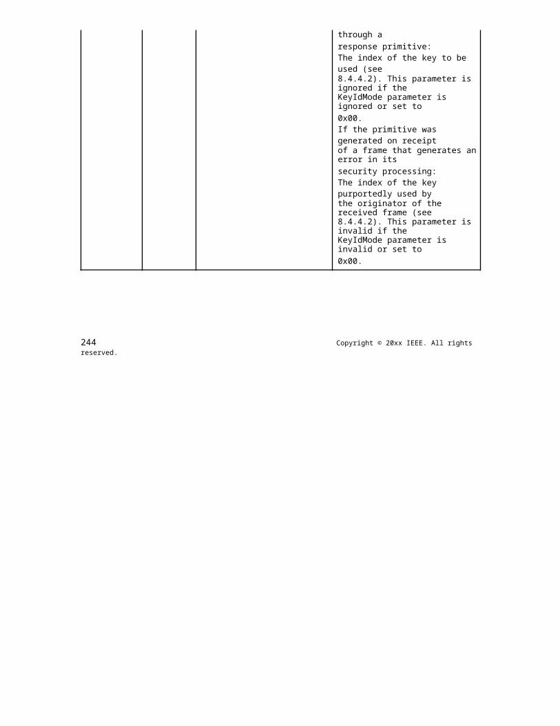
OPTICAL COMMUNICATION IEEE Std 802.15.7r1-20xx
Figure 359—Overview of the standalone link (one link direction)
Following conversion from optical to electrical signal and signal detection, the inverse operations are per-formed at the receiver (Rx), where a frequency-domain equalizer (FDE) is used to reconstruct the received constellation points on each sub-carrier, after passing them through the OWC channel. The desired mapping of information bits onto the sub -carriers is sent by the receiver to the transmitter over the reverse link. In the example shown in Figure 2 2, the metrics reporting is carrying a so-called noise-enhancement vector. A power- and bit-loading algorithm determines the power and modulation formats for the data transport on each used subcarrier. The loading algorithm typically maximizes the throughput assuming a fixed power budget so that a predefined bit error rate (BER) is achieved before forward error correction (FEC).
17.1.2.1 PHY based on G.hn in coax mode
As the above transmission concept is already realized for other media in home environments, such as twisted pair, coax and transmission over plastic optical fibers, the following specifications take references to the ITU-T recommendation for home networking G.hn that has been recently developed for all these media. The requirements of the TCD can be met by
Starting from G.hn PHY baseband coax modes for 50, 100 and 200 MHz bandwidth
adding further modes for scalability towards lower and higher bandwidths
adding new features for the coordinated wireless (COW) topology
adding new features for the wireless relaying (WREL) topology
Starting from the G.hn recommendation is efficient because optical wireless is an emerging technology expecting fast market growth. The home networking community has developed G.hn for several fixed net-working media and is adopting OWC as a next medium to support as an further evolution of G.hn. By align-ing the G.hn evolution with the high-bandwidth mode in 802.15.7r1, a powerful new specification is obtained that fulfills the requirements in the TCD by evolving an existing technology rather defining a new one.
In the following, an implementable overview of the necessary features taken over from 2015 release of G.hn is given it is demonstrated how the existing G.hn PHY can be further developed in order to enable the new COW and WREL modes over the optical wireless link.
17.1.2.2 Adaptive OFDM Waveform
The PHY uses the adaptive OFDM waveform in both link directions with following extensions:
The waveform is always non-negative and real-valued.
Copyright © 2011 IEEE. All rights reserved. 491
IEEE Std 802.15.7r1-20xx IEEE STANDARD FOR SHORT-RANGE WIRELESS
A bias is added and clipping (if needed) is implemented in the digital domain.
Optional single-carrier or unipolar modulation to improve power efficiency and support dimming.
OFDM signal generation is shown in Figure 2 3. A block of 2N data symbols is transmitted. An optional pre-coding is used for the generation of singlecarrier or unipolar modulation schemes based on OFDM to improve power efficiency and support dimming. The signal is then passed through a carrier mapping unit, used for precoding and Hermitian symmetry. Next, the IFFT is performed, the CP is added and controlled clipping is performed in the digital domain.
Figure 360—OFDM signal generation
17.1.2.2.1 Carrier mapping
Carrier mapping is performed as illustrated in Figure 2 4. Note that the subcarrier x0 may be used to add a constant bias signal to the output signal. In order to create a real-valued waveform, only half of the subcarri-ers are used, while conjugate symmetry is enforced as
x_(2N-i)=x_i^* , i=1,2,…N-1.
where the star indicates complex conjugation. The resulting discrete multi-tone (DMT) signal is real-valued, even if symbols xi are complex.
492 Copyright © 20xx IEEE. All rights reserved.
OPTICAL COMMUNICATION IEEE Std 802.15.7r1-20xx
Figure 361—Carrier mapping for standalone link
17.1.2.2.2 IFFT
The time-domain signal X(k) is given by
X(k)=1/2N ?_(i=0)^(2N-1)??x_i e^(j2? ik/2N) ?
where i denotes the sample index, xi the complex-valued baseband signals in the frequency domain and 2N the block size of the IFFT.
17.1.2.2.3 Cyclic prefix
At the output of the IFFT, in the serial block of 2N samples, the last CP samples are copied as a sub- block being repeated and appended at the beginning of the block of samples, see Figure 2 5. By adding the CP at the transmitter, and removing it at the receiver, the multipath channel matrix can be transformed from Toeplitz- shape into a circulant shape, which allows the use of IFFT at the transmitter and FFT at the receiver to obtain a diagonal channel in the frequency domain, so that a simple single-tap frequency-domain equal-izer (FDE) can be used.
Figure 362—Cyclic prefix insertion
Copyright © 2011 IEEE. All rights reserved. 493
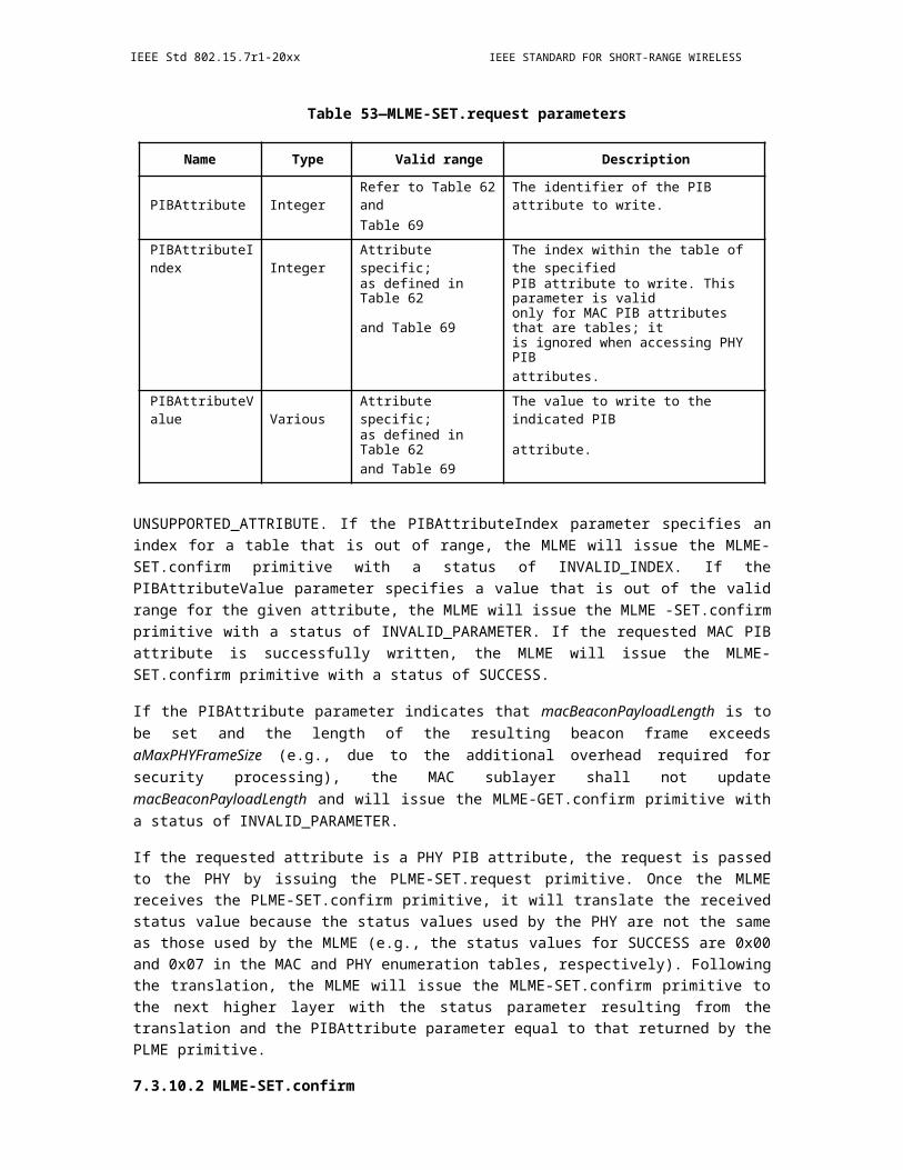
IEEE Std 802.15.7r1-20xx IEEE STANDARD FOR SHORT-RANGE WIRELESS
17.1.2.3 Single-carrier modulation (optional)
Optional pre-coding before the OFDM modulator can be used to reduce the probability of clipping and enhance power efficiency while sacrificing no or minor spectral efficiency [1, 2].
For single-carrier (SC) transmission, "outer" pre-coding, together with an "inner" OFDM transmitter is used to emulate SC transmission inside the OFDM concept. The novel schemes require little more advanced sig-nal processing, and the same minor increase of sophistication can be expected at the receiver, i.e. decoding is straightforward. The schemes are shown in principle in Figure 2 6. Details can be found in [1, 2].
Figure 363—Different precoding schemes can be used to improve the power efficiency of the OFDM transmitter. Top: Pure DFT precoding uses a roll-off factor =0. Center: A root-
raised-cosine filter can be added in the frequency domain, to realize >0. Bottom: A Gauss-ian filter can used in the same way and a minimum-shift keying (MSK) modulation can be
added in the time domain. In this way, the classical GMSK waveform can be realized inside an OFDM system.
Figure 3 7 Different precoding schemes can be used to improve the power efficiency of the OFDM transmit-ter. Top: Pure DFT precoding uses a roll-off factor =0. Center: A root-raised-cosine filter can be added in the frequency domain, to realize >0. Bottom: A Gaussian filter can used in the same way and a minimum-shift keying (MSK) modulation can be added in the time domain. In this way, the classical GMSK waveform can be realized inside an OFDM system.
17.1.2.3.1 DFT-pre-coded OFDM
The simplest SC transmitter is shown in Figure 2 6 row A. First, the symbol sequence is passed through the N-DFT and then mapped directly onto the desired frequency sub -band after using a cyclic shift (CS) so that the DC signal is in the center . Finally, the precoded sequence is passed through the M-IDFT and the cyclic prefix (CP) is added.
As shown in [2], this procedure yields a SC signal having a roll-off factor =0. The rectangular filtering causes "ringing" in the time domain which increases the peak-to-average power ratio (PAPR). As this is a special case of the RRC-filtered SC transmission, details are described in the next subsection.
494 Copyright © 20xx IEEE. All rights reserved.

OPTICAL COMMUNICATION IEEE Std 802.15.7r1-20xx
17.1.2.3.2 RRC-filtered single-carrier modulation
In the middle row in Figure 2 6, an additional root-raised-cosine filter is introduced in the frequency domain where ?0. In order to realize filtering in the frequency domain, oversampling is emulated by repeating the DFT output block in the frequency domain. Afterwards, the root-raised cosine (RRC) filter is applied in the frequency domain. The sequence is then mapped directly onto the desired frequency sub-band using a cyclic shift (CS) so that the DC signal is in the center. In the following, these steps are described in detail.
A data sequence a(n) of length M is used where n = 1, 2, …, M. The sequence is up-sampled by factor F as follows
b(k)={?(a(n) if k=F?n@0 else)?
with F=?2N/M-0.5?, where k = 1, 2, …, F?M and 2N is the number of samples in the final waveform w/o the CP. The notation ?z? is used here to indicate that z is rounded to the nearest integer less than or equal to z. Note that F-times up-sampling followed by M-DFT is equivalent to M-DFT and subsequent spectral repeti-tion, provided that the ratio ?(2N/M) is an integer. The proof is given in [2]. Accordingly, up -sampling and 2N-DFT can be replaced by M-DFT and repeating the output signal in the frequency domain.
Next step is a flexible frequency-domain filter. It is implemented so that bandwidth can be easily changed as a function of the block size M. Therefore, a vector is defined with running index s = [-M, …, M] the bell-shape part of the filter is computed as
G_l=?(0.5(1+cos[(?(|s_l |)-(1-?)?M/2)/(??M)]) )
where l = 1, 2, …2M+1. The filter is transparent in the range
a=[M+1-?((1-?)?M)/2?,…,M+1+?((1-?)?M)/2?]
There are two regions where the filter attenuates totally. They are given by
b=[1,…,M+1-?((1+?)?M)/2?]
c=[M+1+?((1+?)?M)/2?,…,2M+1 ]
Gl is now set as Ga = 1, Gb = 0 and Gc = 0 in the respective regions indicated by vectors a, b and c. Note that up-conversion is equivalent to performing sequentially 2N-DFT of the time-domain sequence, a cyclic shift by Ncenter and 2N-IDFT of the shifted signal, as shown in [2].
Copyright © 2011 IEEE. All rights reserved. 495

IEEE Std 802.15.7r1-20xx IEEE STANDARD FOR SHORT-RANGE WIRELESS
In row B. in Figure 2 6, the synthesis of filtered QAM is summarized in the frequency domain. First the data symbol sequence is passed through the M-DFT and the output is repeated in the frequency domain. Next, the signal is filtered in the frequency domain and the cyclic shift is applied to up-convert the signal to the desired center sub-carrier Ncenter. Finally, the signal is passed through the 2N-IDFT and the cyclic prefix is added [2].
Note that in the SC transmitter, carrier mapping has been modified compared to LTE. In this way, wave-forms become comparable to time-domain single-carrier signal, see [2]. The new mapping is sketched in Figure 2 7.
Figure 364—Generation of filtered single-carrier signals
The direct current (DC) sub-carrier of the M-DFT output vector (having index 1) is first mapped onto the DC sub-carrier of the 2N-IDFT. The two blocks
A=[2…?M/2?] and B=[?M/2?+1…M]
are then mapped onto the first and last sub- carriers, see Fig. 2. Periodic replica are added in the frequency domain to emulate up-sampling. Finally, the frequency-domain filter is applied and the cyclic shift is used to modulate the signal onto the center subcarrier.
17.1.2.3.3 Gaussian minimum shift keying
GMSK is known for zero PAPR in radio links. Although this goal is not reached in OWC links, due to the real-valued waveform, GMSK offers ultra- robust signaling in case of very low SINR. First, the classical time-domain GMSK single-carrier transmitter is reviewed. The serial data symbol sequence a(n) is up-sam-pled as in subsection 2.2.2.5.2 yielding b(k). After applying a Gaussian filter in the time domain, the filtered signal c(k) is obtained. The classical Gaussian filter is approximated in the time domain using a finite impulse response (FIR) with some memory. Next, c(k) is passed into a minimum shift keying (MSK) modu-lator where it is first accumulated yielding the phase
?(k)=?(k-1)+?/2F c(k-1)
496 Copyright © 20xx IEEE. All rights reserved.

OPTICAL COMMUNICATION IEEE Std 802.15.7r1-20xx
and then inserted into the complex amplitude
x(k)=I+jQ=cos?(?(k))+j?sin?(?(k))
Note that in-phase signal I and the quadrature signal Q in are fed by the same phase but at a shift of 90° yielding single side band (SSB) modulation when up-converting the sequence to the desired center fre-quency. This is often performed using an analog IQ modulator. The same SSB up-conversion can be reached by means of digital signal processing. Therefore, the complex-valued GMSK baseband signal is multiplied sample-by-sample with a digitally synthesized complex-valued oscillation due to single OFDM sub-carrier, being the center frequency of the desired GMSK-modulated signal. Finally, a window of length M is applied in the time domain.
The equivalent processing for GMSK using OFDM is summarized on row C. in Figure 2 6. As before, the data sequence a(n) is fed into the M-DFT and up-sampling is emulated by repeating the output signal in the frequency domain. Next, a Gaussian filter is applied in the frequency domain. A vector is created with run-ning index s = [-R, …, R] where R?M, the filter is computed as
G_n=e^(-?^2?s_n^2 ) where ?=?((ln?(2))/2)?1/(M?BT)
where n = 1, 2, ..., 2R +1 and BT is the bandwidth-time product. BT=0.3 is recommended. GMSK is a non-linear SSB phase modulation. Thus, the two functions of accumulating the signal and generating the in-phase and quadrature signals are better realized in the time domain. The main idea is to insert the GMSK modulator after frequency -domain filtering, but in the time domain. Using M-IDFT of the filtered data sequence, c(k) is obtained. Next, c(k) is normalized to unit peak amplitude and feed it into the time-domain MSK modulator described above. Then up-conversion is applied. It can be equivalently implemented as shown in row C in Figure 2 6 or in the time-domain as described above. Finally, the CP is added.
GMSK causes adjacent channel interference since SSB phase modulation is a non-linear process. Even if the GMSK modulator input is confined in the frequency domain, four-wave mixing between in-band sub-carri-ers creates out-of-band interference. Such interference can be cut using an optional post-modulation filter in the frequency domain attenuating totally outside the range s=[?R, ...,R] and correct the power, accordingly.
17.1.2.3.4 From complex- to real-valued single-carrier transmission
The above waveforms yield complex-valued sequences. Same as in the adaptive OFDM approach, the com-plex-valued waveform covers only the first N subcarriers and then Hermetian symmetry is needed to gener-ate a real-valued waveform. Conjugate symmetry is obtained as
x_(2N-i)=x_i^*, i=1,2,…N-1.
The resulting discrete multi-tone (DMT) signal is real-valued, even if symbols xn are complex.
Copyright © 2011 IEEE. All rights reserved. 497
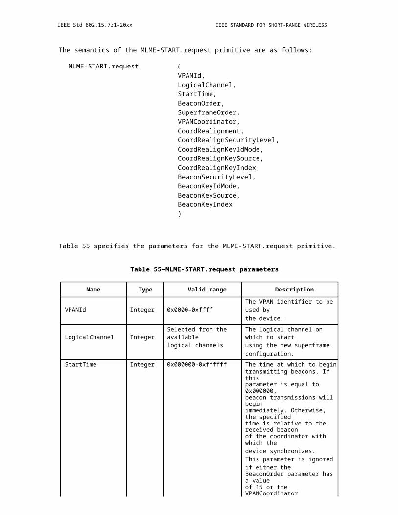
IEEE Std 802.15.7r1-20xx IEEE STANDARD FOR SHORT-RANGE WIRELESS
V. Jungnickel, T. Hindelang, T. Haustein, W. Zirwas, SC-FDMA Waveform Design, Performance, Power Dynamics and Evolution to MIMO, Proc. IEEE Portable, March 2007.
V. Jungnickel, L. Grobe, Localized SC-FDMA with Constant Envelope, Proc. Int. Symp. Personal, Indoor and Mobile Radio Systems (PIMRC), IEEE, London, UK, Sept. 2013, pp. 24-29.
17.1.2.4 Unipolar modulation (optional)
To modulate the intensity of light, the signal needs to be real-valued and non-negative. For adaptive OFDM, besides the Hermitean symmetry operation described in subsection 3.2.2.1, a DC bias has to be added, which results in a reduced power efficiency.
17.1.2.4.1 ACO-OFDM
One way to overcome this disadvantage is asymmetrically-clipped optical (ACO) OFDM as a first unipolar modulation scheme to improve the power efficiency [F-5].
For ACO-OFDM, the time domain signal is made unipolar by simply clipping the negative part at the zero level, which does not need a large DC bias. That is
x_clipped (k)={?(x(k) if x(k)?0@0 else )?
where x (k) is the bipolar real-valued OFDM signal after the IFFT and xclipped(k) the unipolar signal after clipping.
If only the odd subcarriers are modulated by signals, the effect of clipping is that inter-carrier interference (ICI) is created that falls only on the even subcarriers. The effect of clipping on the odd subcarriers is simply a multiplication of these components by a constant 0.5. I.e., clipping does not result in inter-carrier interfer-ence (ICI) on the odd subcarriers, if the even subcarriers remain vacant. The diagram of ACO-OFDM mod-ulation is shown in Figure 3 8.
Figure 365—ACO-OFDM modulation
Figure 3 9 ACO-OFDM modulation
498 Copyright © 20xx IEEE. All rights reserved.
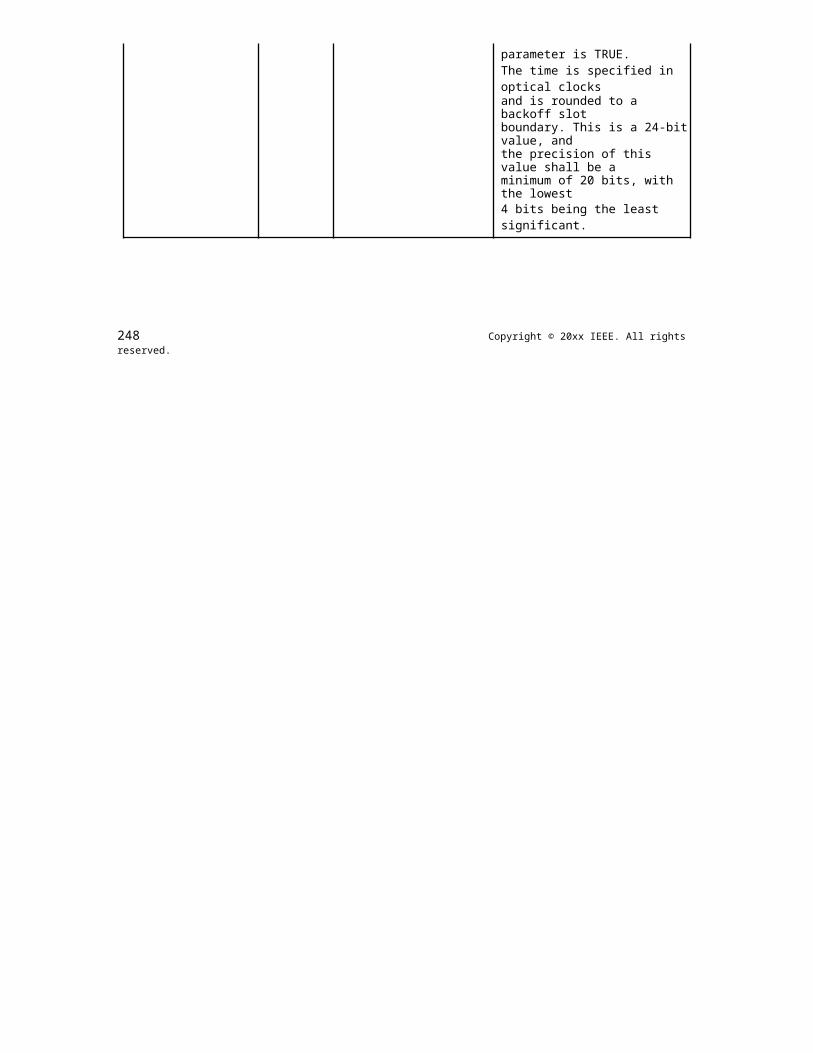
OPTICAL COMMUNICATION IEEE Std 802.15.7r1-20xx
[F-5] Xingxing Huang, Siyuan Chen, Zhixin Wang, Jianyang Shi, Yiguang Wang, Jiangnan Xiao and Nan Chi, "2.0-Gb/s visible light link based on adaptive bit allocation OFDM of a single phosphorescent white LED," IEEE Photonics Journal 7(5), October 2015.
t.b.d.
17.1.2.4.2 eU-OFDM
A real-valued OFDM signal, generated at the PHY layer, is used to modulate the light. The modulation is conducted only within the active operational range of the device. In this range, the electrical signal and the light output signal cannot be negative at all times. The conventional approach is to set a positive operating point, around which the bipolar OFDM signal can be realized. Figure 4 9 (left) illustrates this principle. The positive bias can be introduced as part of the analog front-end (in the case of AC-coupled LED drivers) or as part of the information signal (in case of DC-coupled drivers). This approach is known as DC-biased optical OFDM (DCO-OFDM).
Enhanced unipolar OFDM (eU-OFDM) is an optional alternative modulation scheme. It turns the bipolar OFDM signal into a strictly unipolar information signal without the addition of an energy intensive DC com-ponent that carries no additional information, see Figure 4 9 (right).
Figure 366—Left: Frame start using DC-biased optical OFDM (DCO-OFDM). Right: Same using Enhanced Unipolar OFDM (eU-OFDM)
17.1.2.4.3 Enhanced unipolar OFDM signal generation
The eU-OFDM signals are generated in layers, indicated by the variable STR.
One stream
For one stream, i.e. STR = '00', two consecutive copies of every OFDM symbol are created. The polarity of the samples in the second copy is inverted, and finally, all negative samples in the resulting time -domain double-symbol are set to zero. Any time-domain oversampling and pulse shaping is done after the removal of negative samples. The resulting positive signal is used to modulate the transmitter. The concept is illus-trated in Figure 4 10.
Copyright © 2011 IEEE. All rights reserved. 499
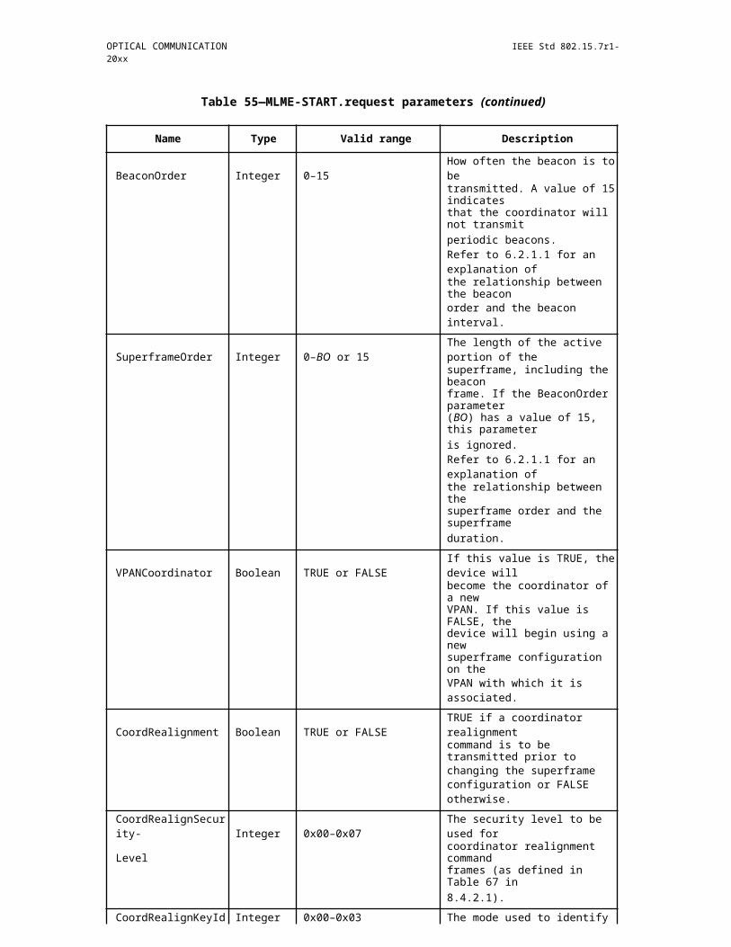
IEEE Std 802.15.7r1-20xx IEEE STANDARD FOR SHORT-RANGE WIRELESS
Two streams
For two streams, STR = '10', every three OFDM symbols are grouped into one eU-OFDM block, where the first two symbols are assigned to stream 1 (St1) and the remaining single symbol is assigned to stream 2 (St2).
The first two symbols in St1 are modulated using the algorithm described for STR='00' and shown in Figure 4 10. The single symbol in St2 is modulated in a similar manner, but instead of two copies, four consecutive copies are created for the OFDM symbol in St2, where the first two copies are kept unchanged, while the polarity of the samples in the next two copies is inverted.
Following this procedure, all negative samples in both St1 and St2 are removed, and the two signals are summed up. Any time-domain oversampling and pulse shaping is done after the removal of the negative samples. The resulting positive signal can be used to modulate the transmitter.
Three streams
For three streams, i.e. STR = '01', every seven OFDM symbols are grouped into an eU-OFDM block, where the first four symbols are assigned to data stream 1 (St1), the next 2 symbols are assigned to data stream 2 (St2) and the last symbol is assigned to data stream 3 (St3).
The four symbols in St1 and the two symbols in St2 are modulated using the algorithm described for two streams, see 4.2.4.2.1.2. The symbol in St3 is modulated in a similar manner, however, eight consecutive copies of that symbol are generated, where the first four copies are left unchanged, while the polarity of the samples in the following four copies is reversed.
Following this procedure, all negative samples in St1, St2 and St3 are removed. Any time- domain oversam-pling and pulse shaping is done after the removal of the negative samples. The signals in the three streams are summed up and the resulting positive signal can be used to modulate the transmitter.
Four streams
For four streams, i.e. STR = '11', every fifteen OFDM symbols are grouped into an eU-OFDM block, where the first eight symbols are assigned to data stream 1 (St1), the next four symbols are assigned to data stream 2 (St2), the following two symbols are assigned to data stream 3 (St3) and the last symbol to data stream 4 (St4).
500 Copyright © 20xx IEEE. All rights reserved.

OPTICAL COMMUNICATION IEEE Std 802.15.7r1-20xx
In the first stream, two consecutive copies of every OFDM symbol are transmitted, where the second copy is multiplied by -1. In the second stream, four consecutive copies of every OFDM symbol are transmitted, where the first two copies are transmitted in their original format, while the signs of the third and the fourth copy are multiplied by - 1. In the third stream, eight consecutive copies of every OFDM symbol are transmit-ted, where the first four copies are conveyed in their original format, while the signs of last four copies are multiplied by -1. In the fourth stream, sixteen consecutive copies of the single OFDM symbol are transmit-ted, where the first eight copies are used in their original format, while the last eight copies are are multiplied by -1.
Finally, all negative samples in the four streams are removed and the signals from the four streams are summed up. Any oversampling and pulse shaping is done after the removal of the negative samples. The resulting positive signal can be used to modulate the transmitter.
Notes on the receiver algorithm
In order to demodulate the data encoded in the first stream (St1), the samples in every even OFDM symbol interval are subtracted from the samples in every odd OFDM symbol interval. For example, the samples in the second symbol are subtracted from the samples in the first symbol, the samples in the fourth symbol are subtracted from the samples in the third symbol, etc. Note that due to the structure of the other data streams (St2 up to St4), the subtraction operation completely removes interference from these streams.
After the subtraction operation, the resulting data at St1 can be demodulated using the conventional OFDM demodulator algorithm. After the data in St1 are demodulated, the stream is re-modulated again and sub-tracted from the overall received signal.
Following the subtraction of the re-modulated St1 signal, all frame copies at St2 which were originally iden-tical (the symbols in question are the symbols that have identical polarity) should be summed up. For exam-ple, the first and the second symbols should be summed, the third and the fourth symbols should be summed, the fifth and the sixth symbols frames should be summed, etc. The resulting signal at St2, then, has the same format as the signal at St1. Hence, it can be demodulated after each even symbol is subtracted from each odd frame. Upon demodulation, the resulting bits can be re-modulated and the resulting waveform can be sub-tracted from the overall received waveform as in the case for St1. The procedure is re-iterated for the remaining streams up to St4 (depending on the configuration) until all data bits are recovered.
17.1.2.5 Multiple-input multiple-output
The use of several multiple-input multiple-output (MIMO) schemes is foreseen in order to support diversity and spatial multiplexing, which can both be realized both as non-imaging and imaging MIMO [F-6, F-7]. The performance of wavelength- division multiplexing (WDM) and wavelength-shift keying (WSK) trans-mission can also be improved by using MIMO transmission schemes.
17.1.2.5.1 Signal model
For two transmitters and two receivers, the signal model for non-imaging MIMO transmission on each sub-carrier can be expressed as
y=(?(y_1@y_2 ))=H?x+n=(?(H_11&H_12@H_21&H_22 ))(?(x_1@x_2 ))+(?(n_1@n_2 ))
where, in general, bold upper case letters describe matrices and bold lower case letters describe vectors. The received signals are denoted as yi where i=1…nRx and nRx is the number of receivers. The transmitted sig-nals are described as xj where j=1…nTx and nTx is the number of transmitters. The channel matrix elements Hij represent the channel gain from the jth transmitter to the ith receiver.
Copyright © 2011 IEEE. All rights reserved. 501
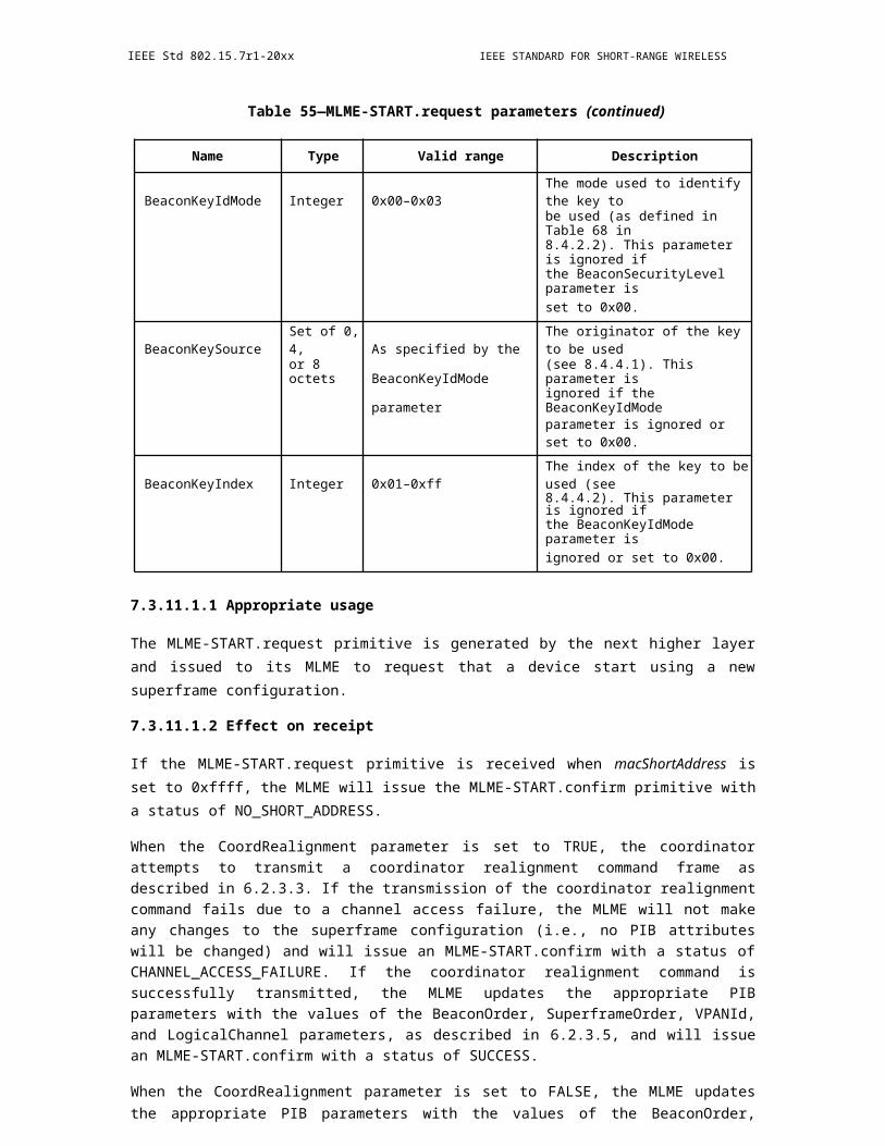
IEEE Std 802.15.7r1-20xx IEEE STANDARD FOR SHORT-RANGE WIRELESS
17.1.2.5.2 Non-imaging MIMO
In case of non-imaging MIMO, see Figure 3 9, light from each of all transmitters (usually having a wide beam) is received by all receivers (usually having wide field-of-views, FOV) , but channels may have differ-ent path loss and impulse response as shown in Figure 6. In case of non-imaging MIMO, the channel matrix H is usually fully occupied and the elements Hij may depend on the subcarrier index n because of the fre-quency response of optoelectronic components and the superposition of LOS and NLOS propagation effects.
Figure 367—Non-imaging MIMO transmission
17.1.2.5.3 Imaging MIMO
Imaging MIMO uses imaging optics between the transmitters and receivers, which are usually arranged in arrays. Because of the lens, the LOS component is often dominant while the diffuse reflections are reduced due to the reduced FOV at the receiver. Ideally, the transmitzter array is imaged 1:1 onto the receiver array. In this case, the channel crosstalk can be neglected, and the channel matrix H has a diagonal shape, i.e. can be simplified and becomes diagonal, i.e.
H_ij={?(H_ii if i=j@0 else)?
Figure 368—Imaging MIMO transmission
502 Copyright © 20xx IEEE. All rights reserved.

OPTICAL COMMUNICATION IEEE Std 802.15.7r1-20xx
17.1.2.5.4 Polarization-division multiplexing
Lights emitting from incoherent LEDs include all polarization directions that can be decomposed as two orthogonal bases, e.g. of horizontal (h) and vertical (v) polarization. For LED-based polarization-division multiplexing (PDM), a linear h-polarizer is inserted that can only allow h-polarized components passing through at the first transmitter (TX1); meanwhile, a linear v-polarizer is used at TX2. Note that many laser diodes yield linearly polarized light so that the transmitter-sided polarizers may not be needed when using lasers. After passing through Tx- sides polarizers, the polarized light is mixed up after free-space propaga-tion. At the receiver (RX), two polarizers are then implemented to filter out the unwanted polarized lights, thus obtaining the transmitting signals.
Figure 369—Polarization-division multiplexing
17.1.2.5.5 Wavelength-division multiplexing
t.b.d.
17.1.2.5.6 Link setup for MIMO
Initial link setup and header transmission detection are performed in the single-input single-output (SISO) mode, in order to improve the reliability of transmission. Transmission of the preamble and the header is done using all transmitters, while detection can be improved by using maximum ratio combining (MRC) based on individual estimates of the superimposed channels from all transmitters at each receiver h_i=?_(j=1)^(n_Tx)?H_ij . The number of used transmitters is included in the header.
17.1.2.5.7 Additional channel estimation symbols for MIMO
Additional channel estimation (ACE) symbols are sent in the beginning of the data field in the PHY frame. They are defined in the frequency domain and over multiple OFDM symbols. Each ACE symbol contains the same sequence of bits on all subcarriers that is only passed through the constellation scrambler. For MIMO, the sequence {sn} contains all 1s, but is multiplied as a whole with a sign taken out of an orthogonal sequence. For 1 transmitter (Tx), the channel estimation symbol in the preamble is used
1 Tx: [{sn}]
For 2 Txs, the first symbol and one ACE signal are sent as
2 Txs:
Tx1 [{sn} {sn}],
Copyright © 2011 IEEE. All rights reserved. 503
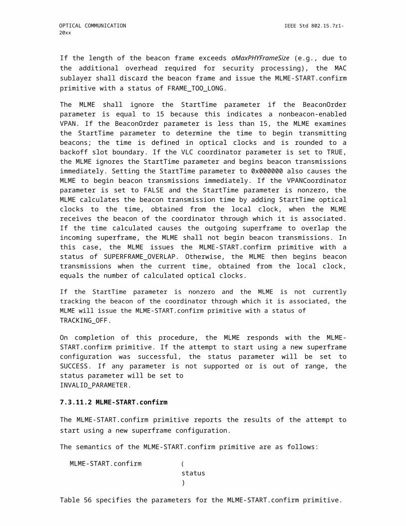
IEEE Std 802.15.7r1-20xx IEEE STANDARD FOR SHORT-RANGE WIRELESS
Tx2 [{sn} {-sn}].
where the first symbol is always contained in the header and only one additional symbol is sent for ACE. The scheme in G.9963 obviously makes use of the Hadamard sequences. It can be easily extended to 4 and 8 transmitters
4 Txs:
Tx1 [{sn} {sn} {sn} {sn}]
Tx2 [{sn} {-sn} {sn} {-sn}],
Tx3 [{sn} {sn} {-sn} {-sn}],
Tx4 [{sn} {-sn} {-sn} {sn}].
8 Txs:
Tx1 [{sn} {sn} {sn} {sn}{sn} {sn} {sn} {sn}]
Tx2 [{sn} {-sn} {sn} {-sn}{sn} {-sn} {sn} {-sn}],
Tx3 [{sn} {sn} {-sn} {-sn}{sn} {sn} {-sn} {-sn}],
Tx4 [{sn} {-sn} {-sn} {sn}{sn} {-sn} {-sn} {sn}].
Tx5 [{sn} {sn} {sn} {sn}{-sn} {-sn} {-sn} {-sn}]
Tx6 [{sn} {-sn} {sn} {-sn}{-sn} {sn} {-sn} {sn}],
Tx7 [{sn} {sn} {-sn} {-sn}{-sn} {-sn} {sn} {sn}],
Tx8 [{sn} {-sn} {-sn} {sn}{-sn} {sn} {sn} {-sn}].
17.1.2.5.8 Adaptive MIMO transmission
In the following, several transmission modes will be described that can be used to operate a MIMO link. The main objective is to enable a dynamic tradeoff between spatial diversiy and spatial multiplexing, so that the best number of streams is always selected to maximize the throughput and to operate the link reliably. It is assumed that the MIMO link will be operated adaptively in a bidirectional closed-loop manner and that MIMO metrics reports regarding the forward link are provided over the reverse link.
Optimal MIMO transmission
Ideally, with having full channel state information conveyed from the receiver to the transmitter, the MIMO transmission can be described as follows. The transmission on each subcarrier is most conveniently formu-lated in the frequency domain as
where the (nTx 1) vector xn contains the signals transmitted from all transmitters at the OFDM sub-carrier with index n. The (nRx 1) vectors yn and n contain the received signals and the noise, respectively. The integers nTx and nRx denote the numbers of transmitters and receivers, respectively.
504 Copyright © 20xx IEEE. All rights reserved.
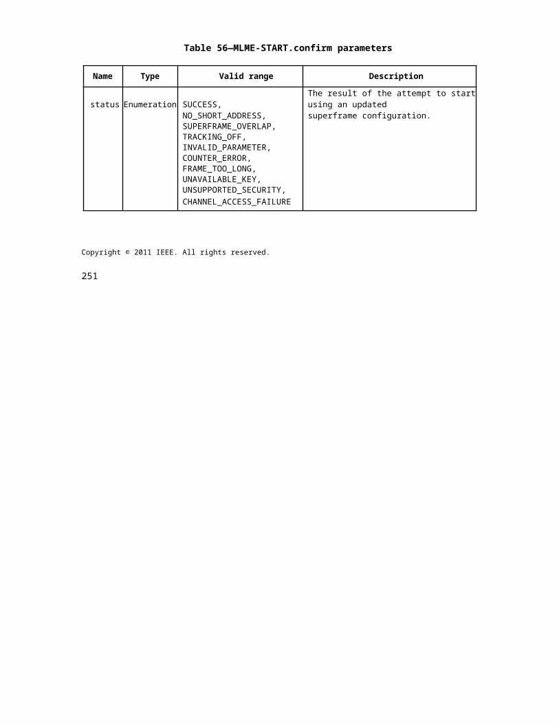
OPTICAL COMMUNICATION IEEE Std 802.15.7r1-20xx
The (nRx nTx) matrix Hn denotes the channel matrix for sub-carrier n with the channel coefficients between each transmitter and each receiver. It is related to the time-domain channel impulse response matri-ces Hl as
where L denotes the number of resolved multi-paths. In the optimal way, based on full channel state infor-mation (CSI) at the transmitter and at the receiver, the channel capacity is approached asymptotically by per-forming a singular value decomposition (SVD) of Hn on each sub-carrier,
which gives the matrices Vn and Un containing the Eigenvectors of the channel matrix in the transmit and receive spaces, respectively.
The diagonal matrix Dn which contains i = 1…min(nTx, nRx) singular values , referred to as the amplitude gains of the spatial Eigenmodes. The superscript H denotes the conjugate transpose of a matrix. In the infor-mation theory, the capacity is asymptotically approached for infinite N by a joint water-filling across all spa-tial Eigenmodes i and all sub-carriers n. Unlike in the information theory, in practise we employ discrete instead of continuous modulation alphabets. A joint bit-loading and power allocation algorithm is therefore used with individual modulation on each Eigenmode and each sub-carrier, according to the current channel state, so that important optimization criteria (throughput, fairness, stability of queues) can be fulfilled.
The transmitted signal vector xn=Vndn is obtained from the data vector dn and the spatially multiplexed data signals are reconstructed at the receiver as . The noise in each stream is boosted differently, according to the singular value for each stream.
Depending on the availability of the CSI, there are modifications. When CSI is available only at the receiver, no pre-processing is applied. Assuming additionally linear detection which requires a simple matrix-vector multiplication, the transmitted signals on each sub-carrier may be reconstructed using the minimum mean-square error detector given by the formula
where I and ² are the (nTx nTx) identity matrix and noise variance at one receiver, respectively.
Figure 370—Adaptive MIMO transmission
Copyright © 2011 IEEE. All rights reserved. 505
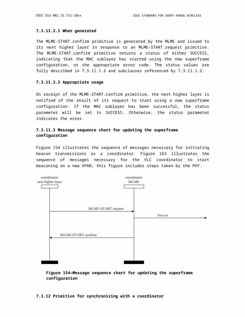
IEEE Std 802.15.7r1-20xx IEEE STANDARD FOR SHORT-RANGE WIRELESS
Practical implementation
Following the optimal MIMO transmission scheme, spatial processing is introduced both at the transmitter and at the receiver, see Figure 8. Moreover, a variable number of streams is used because in some cases, depending on the time-variant wireless channel, a higher capacity is reached with a reduced number of streams. For instance, if an LED is directed away from the receiver, it is hardly useful for transmission and may be switched off.
User data are de- multiplexed yielding Q parallel data streams, where Q is an integer ranging from 1 to nTx. The data in each stream are transported using an individually selectable modulation scheme on each subcar-rier, in order to maximize the throughput, which is also denoted as per-stream rate control. All active streams are then passed through a spatial scheme processing unit, in which channel knowledge, obtained over the reverse link is used to identify the best spatial pre-processing of all streams transported in parallel. It is clear that the MIMO channel rank can vary over time and also as a function of the subcarrier index n. Accord-ingly, and as a natural extension of the adaptive OFDM approach, the selection of the best MIMO transmis-sion mode is done for each subcarrier or for a group of subcarriers. Several simplifications of the spatial processing are introduced now in order to reduce complexity.
MIMO transmission modes
Spatial repetition code: One important simplification is that only one stream is transmitted and received over all LEDs and PDs, respectively. This mode is useful, e.g., in order to create an omnidirectional transmitter characteristics. This can be reached using the precoding vector vn = (1 1 1 1 …1)T.
Transmitter selection: In order to save energy, modulation may be switched off for some LEDs, which results in zeros at the respective positions in the precoding vector vn.
Receiver selection: As only one stream is transmitted using multiple LEDs, maximum ratio com-bining (MRC) is optimal. However, it requires an ADC at each receiver as well as multiple FFTs. Often, few links in the MIMO channel have free LOS and a reduced path loss, accordingly, and for all modulation fre-quencies. Hence, the channel matrix is "sparse". For reduced complexity, it may be sufficient to select the strongest received signals and to combine them using equal gain combining (EGC). This can be realized already in the analog domain so that fewer ADC are sufficient.
Combined transmitter and receiver selection: There can be a combination of transmitter and receiver selection.
Transmitter and receiver selection for multiple streams: The above two schemes can even be com-bined with multi-stream transmission as long as the number of streams Q is equal or smaller than the mini-mum of the numbers of active transmitters and receivers. At the receiver side, the residual cross-talk is then reduced by multi-stream processing.
WDM transmission: For WDM, because different colors are used, normally the number of streams is the same as the number of transmitter ports. In this case, multiple streams are transmitted in parallel and the precoding matrix on all subcarriers is given by Vn = 1n. Because color separation behind the receiver fil-ters may be imperfect, MIMO reference symbols can be transmitted, and MIMO channel estimation and pro-cessing can be performed in order to reduce the residual cross-talk and to increase the spectral efficiency.
WSK transmission: For WSK transmission, e.g. in case of an RGBY LED, the precoding vector vn = (aR aG aB aY)T is used. If MIMO reference symbols are transmitted, imperfect color calibration at the transmitter, which could also be falsified by reflecting surfaces, can be compensated by MIMO processing at the receiver side.
506 Copyright © 20xx IEEE. All rights reserved.

OPTICAL COMMUNICATION IEEE Std 802.15.7r1-20xx
17.1.2.6 Coordinated wireless network
The idea of the coordinated wireless network (COW) is to deploy multiple APs so that continuous coverage is reached for mobile optical wireless user devices in a desired service area. There may be overlapping cov-erage areas, where horizontal handover from one AP to another AP is needed and non -overlapping areas, where vertical handover to another wireless technology is needed. In the following, the overlapping case is described.
17.1.2.6.1 Link setup for COW transmission
Same as in the MIMO mode, initial link setup and header transmission detection are performed in the single-input single-output (SISO) mode, in order to improve the reliability of transmission. Transmission of the preamble and the header is done over all transmitters of all APs. Channel estimation symbols used by differ-ent APs are made orthogonal to each other. Header detection can be improved by using maximum ratio combining (MRC) based on individual estimates of the superimposed channels from all transmitters at each receiver h_i=?_(j=1)^(n_Tx)?H_ij . A list of APs in the jointly served area is included in the header, together with the assigned comb shift, see 4.2.6.2. As described below, the list can include spatial reuse of comb shifts for multiple APs.
Figure 371—Additional channel estimation symbols used in the coordinated wireless net-work. Center: Over multiple ACE symbols, each LED at a given access point transmit another sequence. Subcarriers marked with the same color are assigned to the same
access point. Subcarrier combs can be reused after a certain distance. The assignment of ACE symbols can be defined and changed dynamically by the network management, e.g.
if a new AP is added to the network.
Copyright © 2011 IEEE. All rights reserved. 507

IEEE Std 802.15.7r1-20xx IEEE STANDARD FOR SHORT-RANGE WIRELESS
17.1.2.6.2 ACE symbols for COW transmission
In order to identify different APs in the COW topology and to maintain the possibility to use MIMO at each AP, channel estimation symbols for different APs are made orthogonal in the frequency domain. The general idea is that, during the entire channel estimation block, each AP is assigned another comb of subcarriers (marked with the same specific color in Figure 7), from a set of orthogonal combs [11].
Using a comb of subcarriers only, instead of all subcarriers, is possible because only as many subcarriers are needed for channel estimation as there are taps in the CP, in order to identify all multi- paths. Advanced and computationally efficient algorithms are available in the literature in order to accurately interpolate the chan-nel frequency response based on such subcarrier combs [12]. Note that the same comb can be reused by APs after a certain distance, at which the signal is sufficiently attenuated.
The comb scheme can be extended to MIMO. Based on the comb symbols used for COW transmission, the same rules are applied as for single-cell MIMO, see 4.2.5.7.
17.1.2.6.3 Cell- and user-specific ACE
Note that ACE signals are sent twice in the COW topology. In the first period, also denoted as cell-specific AC (CS-ACE), the ACRE sequence is sent directly from all transmitters, so that the physical channel matrix H is estimated on each subcarrier. This information is useful for joint transmitter optimization, after the AP received the estimated CSI via feedback from its UDs.
In the second period, also denoted as user-specific ACE (US- ACE), the ACE sequence is passed though the transmitter optimization, before being transmitted. Note that the joint transmitter optimization depends on the channel of other UDs attached to other APs as well. Only by using US-ACE, the UD can estimate the modified effective channel matrix Heffective and adapt its receiver processing, accordingly.
17.1.2.6.4 Adaptive COW transmission
t.b.d.
17.1.2.7 Relaying
Relaying operation supports half duplex (HD) and full duplex (DF) duplexing modes as well as amplify and forward (AF) and decode and forward (DF) relaying modes.
17.1.2.7.1 Full duplex (FD) Mode
In FD relaying mode, the REL simultaneously receives and transmits both in uplink and downlink support-ing the AF mode. The method is proprietary.
17.1.2.7.2 Half duplex (HD) relaying
In HD relaying mode, the relay REL shall decode and store the data packets in order to retransmit them to the REL in its transmission period supporting the DF mode. The REL can erase the stored packet after it receives the ACK. The method is proprietary.
17.1.2.8 Payload data
In front of the OFDM modulator (and an eventual preprocessing to generate single-carrier and unipolar sig-nals), payload data are scrambled and then fed into the forward error correction (FEC). Next they are mapped onto constellation points. Finally there is an additional constellation scrambling operation.
508 Copyright © 20xx IEEE. All rights reserved.

OPTICAL COMMUNICATION IEEE Std 802.15.7r1-20xx
17.1.2.9 Data scrambling
For data scrambling, a linear feedback shift register (LSFR) is used. It is defined by the number of registers NLFSR. The position of feedback taps is commonly described via a generator polynomial and the initializa-tion of the registers s1 to sNLFSR.
In Figure 2 8 the LFSR used for data scrambling is shown. It implements the generator polynomial g(x)=x^23+x^18+1 and its register range from s1 to s23.
Figure 372—LFSR for data scrambling
All data starting from the first bit of the PHY-frame header (PFH) and ending by the last bit of the payload shall be scrambled with a pseudorandom sequence generated by this LFSR.
The LFSR generator is initialized at the first bit of the header with the initialization vector equal to 0x2AAAAA in hexadecimal notation or 0010 1010 1010 1010 1010 1010 in binary notation where the LSB corresponds to C1. This initialization is used for the scrambling of the header data. The first bit to be scram-bled shall be XOR'ed with the first bit generated by the LFSR after initialization (i.e., C18 XOR C23 of the initialization vector).
The special value for SI (scrambler initialization) in the PHY-frame header of 016 in hexadecimal notation indicates that the scrambler is not re-initialized between the header and the payload. An initialization of the SI field to values other than the special value is optional, as described in the G.hn specification.
17.1.2.9.1 Forward-error correction
Channel coding for the header
Channel coding for the header uses low-density parity-check codes (LDPC) according to the G.hn standard, see [4]. A short LDPC code of K=168 data bits with code rate ½ is used. The resulting block is modulated with QPSK with repetitions in frequency. If bandwidth is low and SNR shall be increased, the header sym-bol can be repeated in time.
Copyright © 2011 IEEE. All rights reserved. 509
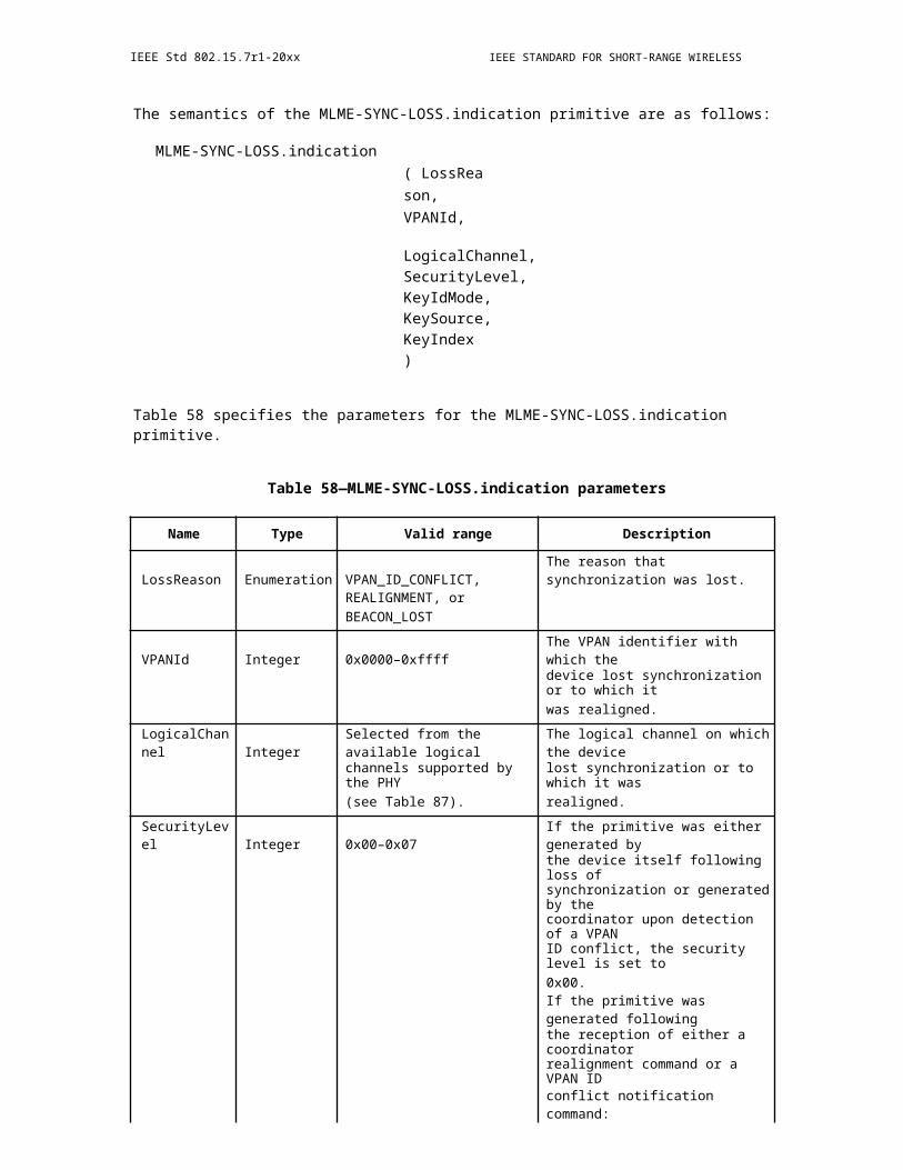
IEEE Std 802.15.7r1-20xx IEEE STANDARD FOR SHORT-RANGE WIRELESS
Figure 373—The low-density parity check code from the G.hn standard is used
Channel coding for the data
Channel coding for the data uses LDPC according to the G.hn standard, see [4]. The LDPC code may be selected between two information block sizes of 4320 or 920 bits bits and 5 code rates of 1/2, 2/3, 5/6, 16/18 or 20/21.
Channel coding for MIMO
Stream-interleaved encoding is used, consistent with the G.hn standard. Stream-wise decoding is not consid-ered, as it would increase both, complexity and latency. To be further detailed.
t.b.d., see G.9960-2015
17.1.2.9.2 Bit-to-Symbol Mapper
t.b.d., see G.9960-2015
17.1.2.9.3 Constellation Scrambling
In Figure 2 9 the LFSR used for the constellation scrambler is shown. It implements the generator polyno-mial g(x)=x^13+x^12+x^11+x^8+1 and its registers range from s1 to s13 being the least significant bit (LSB) and most significant bits (MSB), respectively.
Figure 374—LFSR for constellation scrambling
510 Copyright © 20xx IEEE. All rights reserved.
OPTICAL COMMUNICATION IEEE Std 802.15.7r1-20xx
The phase of the complex symbols generated by the bit-to-symbol mapper is shifted before being fed into the IFFT. The phase shifts are determined by the pseudo-random bit-sequence generated by the LSFR depicted in Figure 2 9. The two LSBs s1 and s2 determine the shift as given by Table 2 1. For a generated phase shift ?_i, the LSFR is shifted by 2i. Due to the constellation scrambling, the phase of an originally generated complex symbol x_i^0 is shifted by ?_i resulting in x_i, the actual input of the IFFT:
x_i=x_i^0?exp?(j?_i).
Insert Table 2 1 - Phase shift values from LFSR states s1 and s2 here
For the header, ACE and payload, the shift of the i-th subcarrier is ? _i and therefore the LSFR is shifted by 2i for each subcarrier. For these cases, the LSFR is initialized to the seed of 1FFFF16 in hexadecimal nota-tion for each OFDM symbol, where the LSB of the seed corresponds to s1.
17.2 PureLiFi Low-bandwidth PHY
17.2.1 Adaptive OFDM Concept
OFDM in the current specification enables a highly adaptive modular implementation, which supports both a high-efficiency PHY mode designed to enable optimal utilization of the low-bandwidth resources (up to 40 MHz of single-sided bandwidth) as well as a low -complexity PHY mode designed to enable high energy efficiency in mobile applications. Furthermore, the specification enables the adaptive and modular introduc-tion of energy-efficient waveforms such as enhanced unipolar OFDM (eU-OFDM), performance enhancing waveforms such as single-carrier FDMA (SC-FDMA) and waveforms designed for improved illumination control such as reverse polarity optical OFDM (RPO-OFDM). In addition, the specification supports the application of adaptive bit and energy loading techniques as well as multiple-input multiple-output (MIMO) techniques which can leverage the additional communication capacity of multiple light sources as well as the additional communication capacity introduced by the utilization of different optical wavelengths and light polarization for communication. The PHY specification supports relaying mechanisms for the cases when dedicated relay terminals are available. A DC-biased optical OFDM (DCO-OFDM) waveform is the basis and the foundation of all concepts, which are specified as optional features and can be applied in a non-conflicting manner.
17.2.2 Waveform
17.2.2.1 Adaptive OFDM signal generation
The adaptive OFDM concept adopted in the current PHY specification allows for adaptive adjustment of the waveform in terms of the carrier mapping as well as in terms of the application of sophisticated signal pro-cessing and dimming techniques such as single-carrier pre-coding, unipolar modulation for improved trans-mission rates and efficiency and reverse polarity OFDM for dimming applications. The specification supports the application of adaptive bit and energy loading techniques as well as adaptive multiple-input multiple-output (MIMO) techniques which can leverage the additional communication capacity of multiple light sources as well as the additional communication capacity introduced by the utilization of different opti-cal wavelengths and light polarization for communication. The individual features of the adaptive signal generation approach are described as follows.
Copyright © 2011 IEEE. All rights reserved. 511

IEEE Std 802.15.7r1-20xx IEEE STANDARD FOR SHORT-RANGE WIRELESS
17.2.2.2 Carrier mapping
The Low-bandwidth PHY mode is required to support fixed carrier mapping. All subcarriers are designated for information transfer by a single communication node in an allocated time interval. No special carrier designation for multiple access techniques exists, and no special carriers are designated for control informa-tion. Depending on whether the current PHY implementation supports adaptive bit allocation for the carrier mapping procedure (an optional feature), the mapping can be described as follows.
17.2.2.2.1 PHY does not support adaptive bit and power allocation
The QAM modulation symbols to which the binary information has been mapped are divided into groups of 24 symbols, where the original order at the output of the QAM modulation encoder is preserved (the bit-stream mapping to QAM symbols is described in subclause 6.3.5). Each ordered group of 24 symbols is mapped to the ordered set of subcarrier indices [3,4,5,6,8,9,10,11,12,13,14,15,16,17,18,19,20,22,23,24,25,26,27,28], where indices 7 and 21 are assigned to fixed pilot values of 1 and -1, respectively. Zeros are assigned to subcarrier indices [0,1,2,29,30,31,32,33,34,62,63]. The Hermitian symmetric sequence of the 26 symbols assigned to indices [3-28] is assigned to subcarrier indices [35-61].
17.2.2.2.2 PHY supports adaptive bit and power allocation
If the PHY mode supports adaptive bit loading, the carrier mapping is determined by means of a bit alloca-tion table negotiated and specified at the MAC layer protocol through an exchange of control and manage-ment frames.
17.2.2.3 6.3.3. IDFT
The IDFT size is fixed in the Low-bandwidth PHY mode to enable lower implementation complexity. The modulation of the different frequency-domain subcarriers is achieved through an IDFT operation, described as follows:
?_(k=0)^63?S [k] e^(j2?k/64) (6.3.3.1)
where S[k] is the symbol mapped to subcarrier index k, as described in 6.3.2. Conventionally, the inverse discrete Fourier transform, as shown in Equation (6.3.3.1), is implemented with an IFFT algorithm. The DFT/IDFT size in the current PHY mode is fixed to 64. The DC subcarrier (subcarrier index 0 in the IFFT operation) and the 180-degree subcarrier (subcarrier index 32 in the IFFT operation) are set to 0. The infor-mation and pilot symbols with coefficients 1 to 26 are mapped to IFFT inputs 3 to 28, while the Hermitian symmetry symbols are mapped onto IFFT inputs 35 to 61. The high-frequency subcarriers, at inputs 29 to 34, form a guard interval and are set to zero. The low-frequency subcarriers, at inputs 0-2 and 62-63, are set to zero in order to avoid possible low-frequency distortion in the system due to baseline wandering and background light interference. The mapping is illustrated in Figure 6.3.3.1. After performing an IFFT, the output is cyclically extended to the desired length as described in 6.3.4.
17.2.2.4 Cyclic prefix
The cyclic prefix size is fixed in the Low-bandwidth PHY mode to enable lower implementation complexity. The cyclic prefix/guard interval (GI) is a cyclic extension of the IDFT result in each OFDM frame, where the cyclic prefix is formed by the last 16 samples of the IDFT result, appended in front of the 64-sample IDFT result. In the current PHY mode, the cyclic prefix size is not variable and cannot be changed.
512 Copyright © 20xx IEEE. All rights reserved.
OPTICAL COMMUNICATION IEEE Std 802.15.7r1-20xx
17.2.2.5 Subcarrier modulation mapping
The OFDM subcarriers shall be modulated by using BPSK, QPSK, 16-QAM, or 64-QAM, depending on the RATE requested. The encoded and interleaved binary serial input data shall be divided into groups of NBPSC (1, 2, 4, or 6) bits and converted into complex numbers representing BPSK, QPSK, 16-QAM, or 64-QAM constellation points. The conversion shall be performed according to Gray-coded constellation map-pings, illustrated in Figure 10, with the input bit, b0, being the earliest in the stream. The output values, d, are formed by multiplying the resulting (I+jQ) value by a normalization factor KMOD, as described in Equation (6.3.5.1).
d = (I + jQ) × KMOD (6.3.5.1)
The normalization factor, KMOD, depends on the base modulation mode, as prescribed in Table 6. Note that the modulation type can be different from the start to the end of the transmission, as the signal changes from SIGNAL to DATA, as shown in Figure 1. The purpose of the normalization factor is to achieve the same average power for all mappings. In practical implementations, an approximate value of the normalization factor can be used, as long as the device conforms with the modulation accuracy requirements.
Insert Table 6: Modulation-dependent normalization factor KMOD here
For BPSK, b0 determines the I value, as illustrated in Table 7. For QPSK, b0 determines the I value and b1 determines the Q value, as illustrated in Table 8. For 16-QAM, b0b1 determines the I value and b2b3 deter-mines the Q value, as illustrated in Table 9. For 64-QAM, b0b1b2 determines the I value and b3b4b5 deter-mines the Q value, as illustrated in Table 10.
Insert Table 7: BPSK encoding table here
Insert Table 8: QPSK encoding table here
Insert Table 9: 16-QAM encoding table here
Insert Table 10: 64-QAM encoding table here
17.2.2.6 Single-carrier modulation (optional)
Optional pre-coding before the OFDM modulator can be used to reduce the probability of clipping and enhance power efficiency. As explained in subclause 6.3.2, the current specification supports loading of 24 subcarriers with unique information. Hence, N<24 M-QAM symbols are passed through an N-point DFT before mapped to subcarriers [3, 4, 5, 6, 8, …, 20, 22, …, 28] as illustrated in Fig. 6.3.3.1. The DFT is com-puted as:
?_(k=0)^(N-1)?S [k] e^((-j2?k)/N) (6.3.6.1)
and the output result is mapped onto the different subcarriers in the order [12, 13, 14, …, 23, 0, 1, 2, …, 11] ? [3,..,6,8,…,20,22,…,28]. If N<24, then the result of the N-point DFT is mapped to the middle of the 24 data subcarriers using the order ['0', '0', …, '0', floor(N/2)+1, floor(N/2)+2, …, N-1 0, 1, 2, …, floor(N/2), '0', …, '0', '0'] ? [3,..,6,8,…,20,22,…,28], where '0' corresponds to a zero value placed on that respective subcar-rier since there are less values than subcarriers. When N<24, the spectral efficiency is reduced. If N<24, the output of the N-point DFT is replicated floor(24/N) times before mapped to the 24 data -carrying subcarriers. Any subcarriers not loaded with information are set to '0'. For example, if N=9, then the output of the 10-
Copyright © 2011 IEEE. All rights reserved. 513
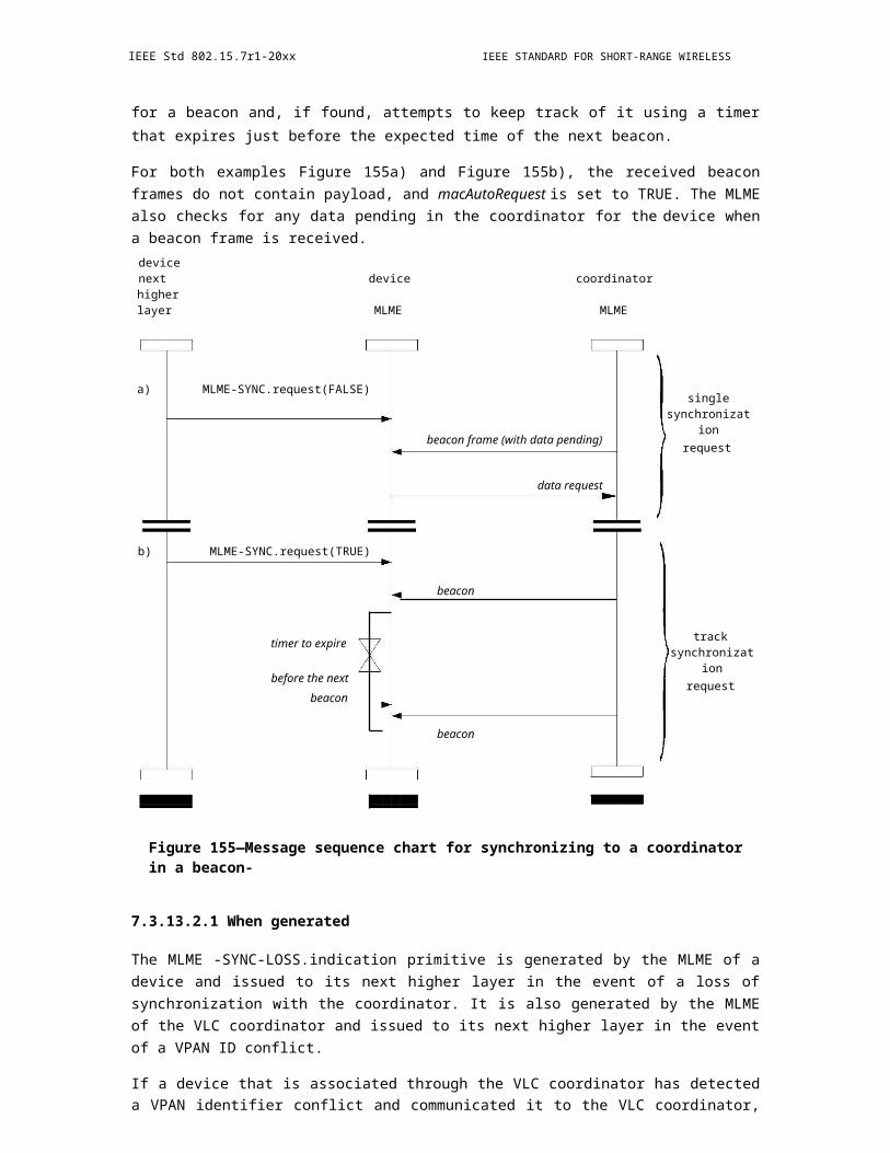
IEEE Std 802.15.7r1-20xx IEEE STANDARD FOR SHORT-RANGE WIRELESS
point DFT is organized in the order ['0', '0', '0', 0, 1, 2, 3, 4, 5, 6, 7, 8, 0, 1, 2, 3, 4, 5, 6, 7, 8, '0', '0', '0']. If N=6, then the output of the 6-point DFT is organized in the order [0, 1, 2, 3, 4, 5, 0, 1, 2, 3, 4, 5, 0, 1, 2, 3, 4, 5, 0, 1, 2, 3, 4, 5]. If N=5, then the output of the 5-point DFT is organized in the order ['0', '0', 0, 1, 2, 3, 4, 0, 1, 2, 3, 4, 0, 1, 2, 3, 4, 0, 1, 2, 3, 4, '0', '0']. In all implementations, the DC value (value with index 0) of the DFT-precoding output should be mapped to the 13th data subcarrier (subcarrier 16 of the IDFT presented in Fig. 6.3.3.1). Figure 6.3.6.1 illustrates the concept, where for the presented examples in this subclause, A=[0, 1, 2, …, 11] B=[12, 13, 14, …, 23], A=[0, 1, 2, 3, 4] B=[5, 6, 7, 8], A=[0, 1, 2] B=[3, 4, 5], and A=[0, 1, 2] B=[3, 4], respectively. If more than one copy of the N -DFT output is mapped onto the OFDM subcarri-ers, a pulse shaping filter such as a root-raised cosine filter can be used to shape the signal spectrum centred around subcarrier 16. The filter should not be applied to the pilot subcarriers (at positions 7 and 21 of the 64-point IDFT operation described in 6.3.2.1 and 6.3.3) as this might lead to significant attenuation of the pilot values, which are necessary for phase correction at the receiver. The use of the RRC filter is indicated with the value SC bits specified in subclause 6.2.3.2.5.
Figure 375—SC-OFDMA subcarrier mapping
17.2.2.7 Unipolar modulation (optional)
The real time- domain OFDM signal, generated at the PHY layer, is used to modulate the light emitting device (a light emitting diode (LED) or a laser diode (LD)), which serves as the transmitter front -end. The modulation is conducted only within the active operational range of the device. In this range, the electrical signal and the light output signal can only be positive at all times. The conventional approach for modulating the LED active range with an OFDM signal shall be to set a positive operating point, around which the bipo-lar OFDM signal can be realized. Figure 6.3.7.1(a) illustrates this principle. The positive bias can be intro-duced as part of the analog front-end (in the case of AC-coupled LED drivers) or as part of the information signal (in case of DC-coupled drivers). This approach is known as DC-biased optical OFDM (DCO-OFDM).
Figure 376—LED active range modulation
514 Copyright © 20xx IEEE. All rights reserved.

OPTICAL COMMUNICATION IEEE Std 802.15.7r1-20xx
An optional alternative modulation approach termed enhanced unipolar OFDM (eU-OFDM) is introduced in this subclause. It constitutes a digital processing algorithm, which can turn the bipolar OFDM signal into a strictly unipolar information signal without the addition of an energy intensive DC component that carries no additional information.
The transmitter signals to the receiver the new transmission PHY mode using the eU and STR bits in the advanced modulation PHY header. For compliance purposes, the PLCP preamble and the PHY headers are encoded in a DCO-OFDM fashion as described in 3.3 - 3.5. Following the four BPSK OFDM symbols con-taining the PHY header, as well as the NMIMO reference symbols when applicable, the data field is encoded in an eU-OFDM fashion (see Fig. 6.3.7.1(b)). The eU-OFDM algorithm works as follows.
TX algorithm
STR = '00'
Two consecutive copies of every OFDM symbol are generated. The polarity of the samples in the second copy is inverted, and finally, all negative samples in the resulting time-domain signal are set to zero. Any time-domain oversampling and pulse shaping should be done after the removal of the negative samples. The resulting positive signal can be used to modulate the transmitter. The concept is illustrated in Fig. 6.3.7.2.
STR = '10'
Every three OFDM symbols are grouped into an eU-OFDM block, where the first two symbols are assigned to data stream 1 (St1) and the remaining one symbol is assigned to data stream 2 (St2). The two symbols in St1 are modulated using the algorithm described for STR='00' and presented in Fig. 6.3.7.2. The symbol in St2 is modulated in a similar manner, but instead of two copies, four consecutive copies are created for the OFDM symbol in St2, where the first two copies are kept unchanged, while the polarity of the samples in the next two copies is inverted. Following this procedure, all negative samples in both St1 and St2 are removed, and the two signals are summed. Any time-domain oversampling and pulse shaping should be done after the removal of the negative samples. If done before the negative samples are removed, the oversampling and
pulse shaping should also be performed at the receiver side during the signal re-modulation process required for the data recovery as explained in the RX algorithm. The resulting positive signal can be used to modulate the transmitter. The concept is presented in Fig. 6.3.7.3.
Copyright © 2011 IEEE. All rights reserved. 515
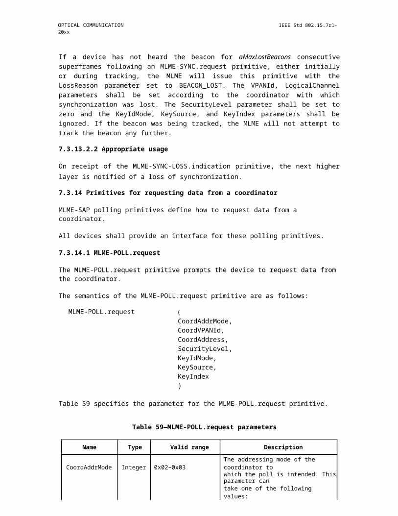
IEEE Std 802.15.7r1-20xx IEEE STANDARD FOR SHORT-RANGE WIRELESS
Figure 377—Unipolar OFDM generation (one stream)
STR = '01'
Every seven OFDM symbols are grouped into an eU-OFDM block, where the first four symbols are assigned to data stream 1 (St1), the next 2 symbols are assigned to data stream 2 (St2) and the last symbol is assigned to data stream 3 (St3). The four symbols in St1 and the two streams in St2 are modulated using the algorithm described for STR='10' and presented in Fig. 6.3.7.3. The symbol in St3 is modulated in a similar manner, however, eight consecutive copies of that symbol are generated, where the first four copies are left unchanged, while the polarity of the samples in the following four copies is reversed. Following this proce-dure, all negative samples in St1, St2 and St3 are removed. Any time-domain oversampling and pulse shap-ing should be done after the removal of the negative samples. If done before the negative samples are removed, the oversampling and pulse shaping should also be performed at the receiver side during the signal re-modulation process required for the data recovery as explained in the RX algorithm. The signals in the three streams are summed and the resulting positive signal can be used to modulate the transmitter. The con-cept is presented in Fig. 6.3.7.4.
Figure 378—Unipolar OFDM generation (two streams)
516 Copyright © 20xx IEEE. All rights reserved.
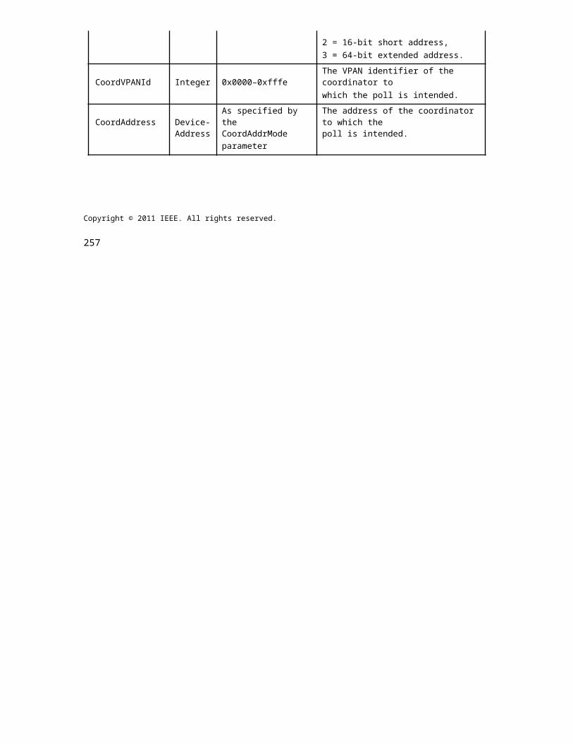
OPTICAL COMMUNICATION IEEE Std 802.15.7r1-20xx
Unipolar OFDM generation (three streams)
STR = '11'
Every fifteen OFDM symbols are grouped into an eU-OFDM block, where the first eight symbols are assigned to data stream 1 (St1), the next four symbols are assigned to data stream 2 (St2), the following two symbols are assigned to data stream 3 (St3) and the last symbol is assigned to data stream 4 (St4). In the first stream, two consecutive copies of every OFDM symbol are transmitted, where the second copy is multiplied by -1 (the signs of all samples are inverted in the time-domain) as described in the cases for STR = '00', STR = '10' and STR = '01'. In the second stream, four consecutive copies of every OFDM symbol are transmitted, where the
first two copies of the symbol are transmitted in their original format, while the signs of the time-domain samples of the third and the fourth copy are inverted, i.e., the samples are multiplied
by -1 as described in the cases for STR='10' and STR = '01'. In the third stream, eight consecutive copies of every OFDM symbol are transmitted, where the first four copies are conveyed in their original format, while the signs of the time-domain samples of the fifth, sixth, seventh and eighth copy are inverted, i.e., the sam-ples are multiplied by -1 as described in the case for STR = '01'. In the fourth stream, sixteen consecutive copies of every OFDM symbol are transmitted, where the first eight copies are conveyed in their original format, while the signs of the time-domain samples of the ninth, tenth, eleventh and twelfth, thirteenth, four-teenth, fifteenth and sixteenth copy are inverted, i.e., the samples are multiplied by -1 At this point, all nega-tive samples in the four streams are removed and the signals from the three streams are added together. Any oversampling and pulse shaping should be done after the removal of the negative samples. If done before the negative samples are removed, the oversampling and pulse shaping should also be performed at the receiver side during the signal re-modulation process required for the data recovery as explained in the RX algo-rithm. The resulting positive signal can be used to modulate the transmitter.
RX algorithm
In order to demodulate the data encoded in the first stream (St1), the samples in every even OFDM symbol interval are subtracted from the samples in every odd OFDM symbol interval. For example, the samples in
Copyright © 2011 IEEE. All rights reserved. 517
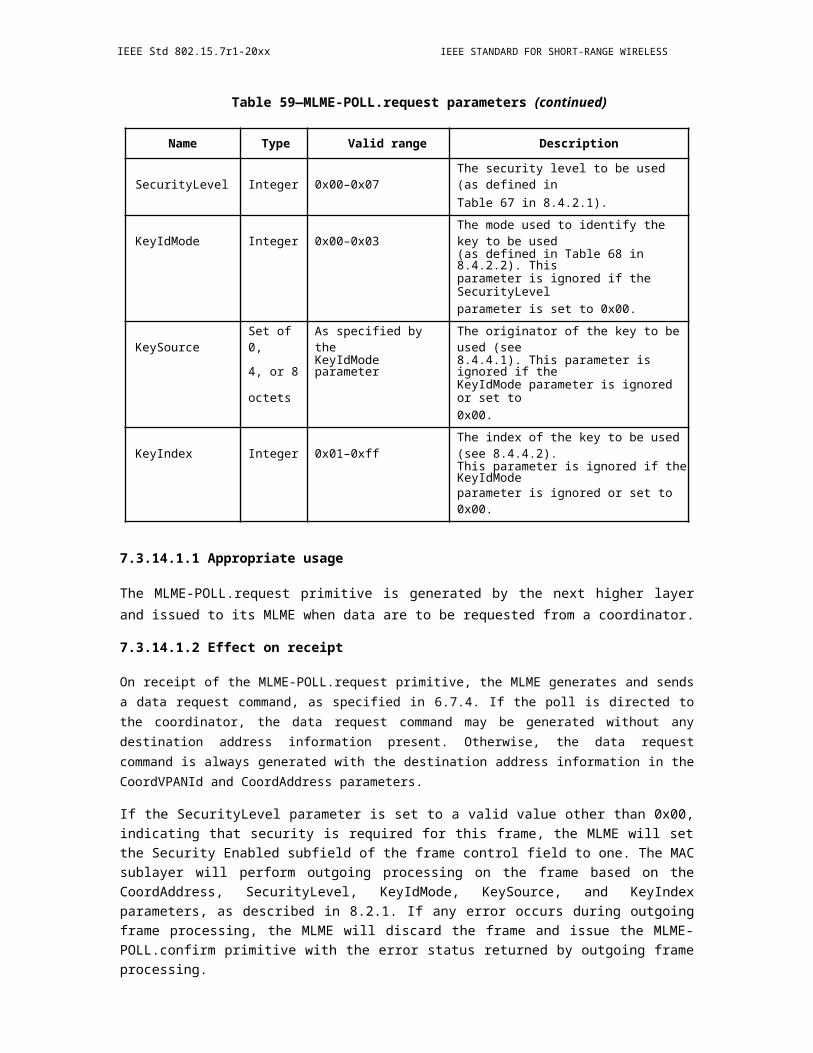
IEEE Std 802.15.7r1-20xx IEEE STANDARD FOR SHORT-RANGE WIRELESS
the second interval are subtracted from the samples in the first interval, the samples in the fourth interval are subtracted from the samples in the third interval, etc. Note that due to the structure of the other data streams (St2 up to St4), the subtraction operation completely removes interference from these streams. After the sub-traction operation, the resulting data at St1 can be demodulated using the conventional OFDM demodulator algorithm. After the data at St1 is demodulated, the stream is re -modulated again and subtracted from the overall received signal. If time-domain oversampling and pulse shaping has been conducted in the time-domain before the negative samples have been removed in the signal generation procedure, then the same procedure (including the subsequent matched filtering at the receiver) should be applied to the re-modulated signal before it is subtracted from the overall received stream. Following the subtraction of the re-modulated St1 signal, all symbol copies at St2 which were originally identical (the symbols in question are the symbols that have identical polarity) should be summed. For example, in Fig. 6.3.7.3, the first and the second sym-bols should be summed, the third and the fourth symbols should be summed, the fifth and the sixth symbols should be summed, etc. The resulting signal at St2, then, has the same format as the signal at St1. Hence, it can be demodulated after each even symbol is subtracted from each odd symbol. Upon demodulation, the resulting bits can be re- modulated and the resulting waveform can be subtracted from the overall received waveform as in the case for St1. The procedure is re-iterated for the remaining streams up to St4 (depending on the configuration) until all data bits are recovered.
Figure 379—RPO-OFDM signal
17.2.2.8 Dimming (move to clause 9.5)
Reverse polarity optical OFDM (RPO-OFDM) is defined as an optional feature in this specification to facil-itate dimming capabilities. This modulation scheme is expected to work in conjunction with eU-OFDM, but it can also be realized using DCO-OFDM. The eU-OFDM specification should be used for the generation of a unipolar signal, which would be indicated with the 'eU' bit defined in subclause 6.2.3.2. The current sub-clause provides the means for generating a RPO-OFDM signal using the DCO-OFDM waveform or the eU-OFDM waveform generated using the eU- OFDM specification. Note that RPO-OFDM modulation does not prevent the use of SC-OFDMA precoding and/or adaptive bit loading and/or MIMO encoding.
The RPO-OFDM modulation incorporates dimming while maintaining the average power per time-domain OFDM symbol and eliminating energy-intensive and adaptive DC component that carries no additional
518 Copyright © 20xx IEEE. All rights reserved.
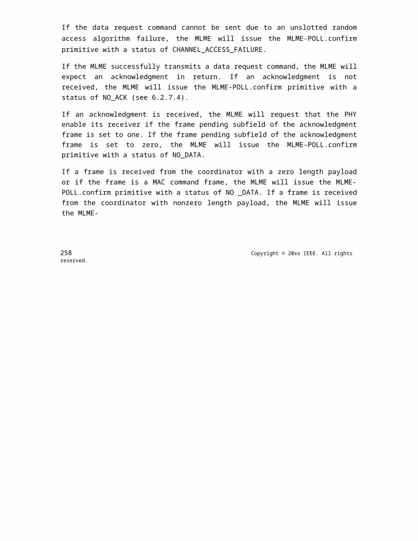
OPTICAL COMMUNICATION IEEE Std 802.15.7r1-20xx
information. Accordingly, a constant signal-to-noise ratio (SNR) for a wide dimming range is achieved, the full active operational range of the device is utilized and high energy efficiency is realized. Here, the time-domain samples polarity of individual OFDM symbols is properly set to generate an OFDM waveform that has similar characteristics of a pulse-width modulation (PWM) signal in controlling the dimming percent-age. Such OFDM waveform also has two periods equivalent to the "on-time" and "off-time" periods of a PWM signal. Over an equivalent PWM period, the average forward current through the device is equivalent to the target dimming percentage. Assuming a 1W maximum optical power, the RPO-OFDM signal for two different dimming ratios of 70% and 20% duty-cycles (D) are shown in Fig. 6.3.8.1. The method of deriving the RPO-OFDM is detailed in H. Elgala and T.D.C. Little, "Reverse polarity optical OFDM (RPO- OFDM): dimming compatible OFDM for gigabit VLC links", Optics Express, vol. 21, issue 20, pp. 24288 - 24299, 2013.
Figure 380—RPO-OFDM modulation signal
The PHY header information and MIMO reference symbols are transmitted using the default DCO-OFDM format. The OFDM symbols encoded in a DCO-OFDM/SC-OFDMA/eU-OFDM format are modified as fol-lows. The first max(min(NOFDM,127) - NRPO , 0) symbols are transmitted as GRPOSOFDM/32 + Smin, where SOFDM is the time-domain DCO-OFDM/SC-OFDMA/eU-OFDM signal, Smin is the minimum possible signal bias level and NOFDM is the number of OFDM data symbols remaining until the end of the packet. The following min(NOFDM , NRPO) symbols are transmitted as Smax - GRPOSOFDM/32, where Smax is the maximum possible signal bias level. The scaling factor GRPO enables the data-carrying part of the signal to be scaled independently from the part of the signal which contains the control information in the PHY headers, which enables more robust transmission of the control information. The time-domain modulation signal generated using this approach is illustrated in Fig. 6.3.8.1. The value of NRPO is speci-fied in subclause 6.2.3.2.7 and the value of GRPO is specified in sublcause 6.2.3.2.8.
Figure 381—MIMO reference symbols format I
Copyright © 2011 IEEE. All rights reserved. 519

IEEE Std 802.15.7r1-20xx IEEE STANDARD FOR SHORT-RANGE WIRELESS
17.2.3 MIMO
17.2.3.1 Modified frame structure
In MIMO mode, the PHY layer frame structure is modified with the addition of the MIMO reference sym-bols (see Fig. 6.2.1) described in the following subclause 6.4.2.
17.2.3.2 Reference symbols for MIMO channel estimation
MIMO reference symbols format II
17.2.3.2.1 MIMO Reference Symbols Format I
The MIMO reference symbols consist of NMIMO OFDM frame intervals. For each MIMO transmitter, only one OFDM frame interval is set to the desired channel estimation sequence (CES). All other intervals are set to zero. At the same time, the CES transmission intervals never coincide for any two transmitters. Hence, the MIMO reference symbols for the different transmitters are orthogonal to each other. The format is presented in Fig. 6.4.2.1.1.
17.2.3.2.2 MIMO Reference Symbols Format II
The MIMO reference symbols consist of NMIMO OFDM frame intervals. Every frame interval is set to the desired channel estimation sequence (CES). In addition, the CESs for each transmitter are modified by adjusting the polarity of the individual CES sequences according to a pre-determined set of Walsh sequences, where a value of '1' in the Walsh sequence corresponds to an unmodified CES sequence while a value of '-1' corresponds to a CES sequence with reverse polarity. The format is presented in Fig. 6.4.2.2.1. The CES sequences in white are left unmodified, while the CES sequences in gray are multiplied by -1.
520 Copyright © 20xx IEEE. All rights reserved.

OPTICAL COMMUNICATION IEEE Std 802.15.7r1-20xx
The Walsh sequences for a MIMO configuration with two transmitters (NMIMO = 2) correspond to the rows of the matrix W2MIMO:
1 1
1 -1
The Walsh sequences for four transmitters (NMIMO = 4) correspond to the rows of the matrix W4MIMO:
1 1 1 1
1 -1 1 -1
1 1 -1 -1
1 -1 -1 1
The Walsh sequences for four transmitters (NMIMO = 8) correspond to the rows of the matrix W8MIMO:
1 1 1 1 1 1 1 1
1 -1 1 -1 1 -1 1 -1
1 1 -1 -1 1 1 -1 -1
1 -1 -1 1 1 -1 -1 1
1 1 1 1 -1 -1 -1 -1
1 -1 1 -1 -1 1 -1 1
1 1 -1 -1 -1 -1 1 1
1 -1 -1 1 -1 1 1 -1
As a general rule,
W2^kMIMO =
W2^(k-1)MIMOW2^(k-1)MIMO
Copyright © 2011 IEEE. All rights reserved. 521
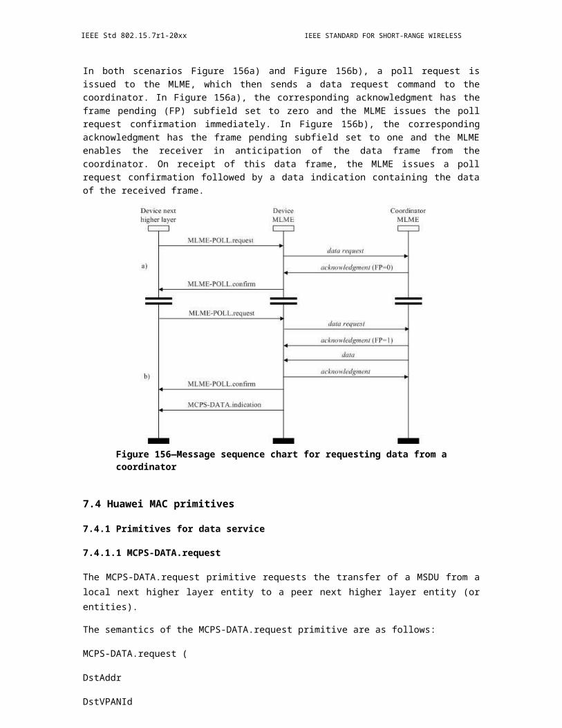
IEEE Std 802.15.7r1-20xx IEEE STANDARD FOR SHORT-RANGE WIRELESS
W2^(k-1)MIMO- W2^(k-1)MIMO
Figure 382—Repetition coding for MIMO communication
Figure 383—Repetition coding for MIMO communication
17.2.3.3 6.4.3. MIMO transmission modes
The system supports up to MMIMO=8 transmitters and NMIMO=8 receivers. MIMO operation mode refers to the combination of selected transmission type and configuration. MIMO configuration refers to the active number of transmitters and receivers. Based on the communication channel conditions, a MIMO system with MMIMO transmitters and NMIMO receivers (denoted as MMIMO × NMIMO MIMO) may operate using only Mactive < MMIMO transmitters and Nactive < NMIMO receivers. For example, an 8×8 MIMO system may operate as a 4×4 MIMO system keeping only a subset of their transmitters and receivers active.
Supported transmission types are repetition coding and spatial multiplexing. The transmission type for the individual transmitter elements and the subcarrier loading is negotiated at the MAC layer. The receiver mon-itors the MIMO operation modes using the MIMO reference symbols and signals the mode as well as the subcarrier loading using control frames in the MAC layer.
17.2.3.3.1 6.4.3.1. Spatial Repetition Coding:
In the repetition coding (RC), the same information is transmitted from more than one transmit elements. The concept is illustrated in Fig. 6.4.3.1.1 for a 2×2 MIMO system.
522 Copyright © 20xx IEEE. All rights reserved.

OPTICAL COMMUNICATION IEEE Std 802.15.7r1-20xx
Figure 384—MIMO mode selection algorithm
17.2.3.3.2 Spatial Multiplexing:
In the spatial multiplexing (SMUX) more than one transmit element sends independent information. The concept is illustrated in Fig. 6.4.3.2.1 for a 2×2 MIMO system.
The MIMO mode selection and adaptive bit loading routine is expected to follow the algorithm described in Fig. 6.4.3.1. In the figure, the constraint metric denotes quality of service requirements that must be satisfied in a given application, for example the level of maximum bit error rate. The performance metric denotes a quality of service metric which the system attempts to optimize, such as the Phy_ SAP data rate. Valid data rates for spatial multiplexing MIMO communication with different number of transmitted streams are shown in Table 6.4.3.2.1 to 6.4.3.2.5.
Insert Table 6.4.3.2.1: Valid rate values for MIMO Spatial Multiplexing for 5 MHz Bandwidth
Insert Table 6.4.3.2.2: Valid rate values for MIMO Spatial Multiplexing for 10 MHz Bandwidth
Insert Table 6.4.3.2.3: Valid ratevalues for MIMO Spatial Multiplexing for 15 MHz Bandwidth
Copyright © 2011 IEEE. All rights reserved. 523

IEEE Std 802.15.7r1-20xx IEEE STANDARD FOR SHORT-RANGE WIRELESS
Insert Table 6.4.3.2.4: Valid rate values for MIMO Spatial Multiplexing for 20 MHz Bandwidth
Insert Table 6.4.3.2.5: Valid rate values for MIMO Spatial Multiplexing for 40 MHz Bandwidth
17.2.4 Channel coding
The PPDU is coded with a convolutional encoder of coding rate R = 1/2, 2/3, or 3/4, corresponding to the desired data rate. The convolutional encoder shall use the industry- standard generator polynomials, g0 = 1338 and g1 = 1718, of rate R = 1/2, as shown in Figure 6.5.1. The bit denoted as "A" is output from the encoder before the bit denoted as "B". The summation operation presented in Fig. 6.5.1 is a modulo-2 sum-mation, i.e., an XOR operation. Higher rates are derived from this encoding mechanism by employing "puncturing." Puncturing is a procedure for omitting some of the encoded bits in the transmitter (thus reduc-ing the number of transmitted bits and increasing the coding rate) and inserting a dummy "zero" metric into the convolutional decoder on the receive side in place of the omitted bits. The puncturing patterns are illus-trated in Figure 6.5.2. Decoding by the Viterbi algorithm is recommended.
17.2.4.1 Channel coding for the header
The PHY headers (both the basic header and the advanced modulation header) are encoded using 1/2 rate FEC coding (no puncturing is used). The encoded bits are also mapped to a BPSK symbol constellation.
17.2.4.2 Channel coding for the data
524 Copyright © 20xx IEEE. All rights reserved.

OPTICAL COMMUNICATION IEEE Std 802.15.7r1-20xx
The DATA field, composed of SERVICE, PSDU, tail, and pad parts, is coded using the rate specified by the MAC layer protocol.
17.2.4.3 Data interleaving
Figure 385—Convolution encoder (133,171)
All encoded data bits shall be interleaved by a block interleaver with a block size corresponding to the num-ber of bits in two OFDM symbols, 2NCBPS. The interleaver is defined by a two-step permutation. The first permutation ensures that adjacent coded bits are mapped onto nonadjacent subcarriers. The second ensures that adjacent coded bits are mapped alternately onto less and more significant bits of the constellation and, thereby, long runs of low reliability (LSB) bits are avoided. The index of the coded bit before the first per - mutation shall be denoted by k; i shall be the index after the first and before the second permutation; and j shall be the index after the second permutation, just prior to modulation mapping.
The first permutation is defined by the rule:
i = (2NCBPS/16) (k mod 16) + floor(k/16) k = 0, 1, …, 2NCBPS - 1 (5)
The function floor (.) denotes the largest integer not exceeding the parameter.
The second permutation is defined by the rule
j = s × floor(i/s) + (i + 2NCBPS - floor(16 × i/2NCBPS)) mod s i = 0, 1, … 2NCBPS - 1 (6)
The value of s is determined by the number of coded bits per subcarrier, NBPSC, according to
s = max(NBPSC/2,1) (7)
Copyright © 2011 IEEE. All rights reserved. 525
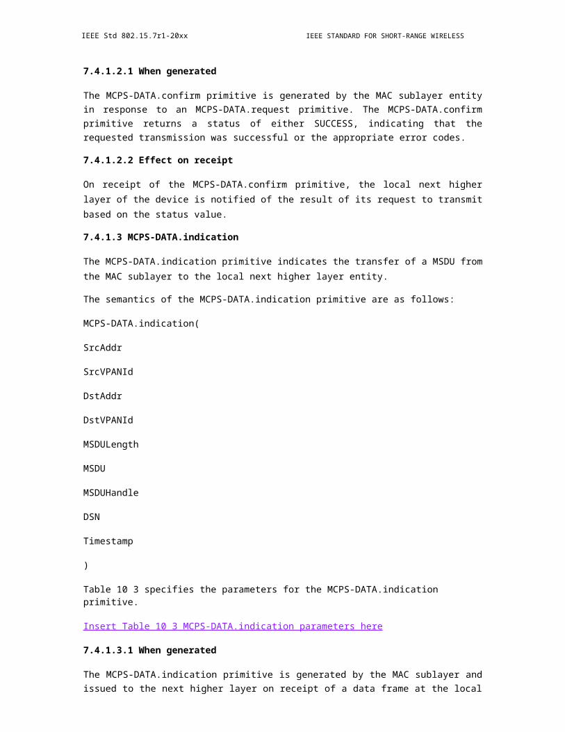
IEEE Std 802.15.7r1-20xx IEEE STANDARD FOR SHORT-RANGE WIRELESS
The deinterleaver, which performs the inverse relation, is also defined by two permutations.
Here the index of the original received bit before the first permutation shall be denoted by j; i shall be the index after the first and before the second permutation; and k shall be the index after the second permutation, just prior to delivering the coded bits to the convolutional (Viterbi) decoder.
The first permutation is defined by the rule
i = s × floor(j/s) + (j + floor(16 × j/(2NCBPS))) mod s j = 0, 1, … 2NCBPS - 1 (8)
where s is defined in Equation (7).
This permutation is the inverse of the permutation described in Equation (6). The second permutation is defined by the rule:
k = 16 × i - (2NCBPS - 1)floor(16 × i/(2NCBPS)) i = 0, 1, … 2NCBPS - 1 (9)
This permutation is the inverse of the permutation described in Equation (5).
17.2.5 Relaying
17.2.5.1 Amplify and forward
The PPDU is buffered at the receiving node and upon successful demodulation of the advanced modulation header and identification of the amplify and forward specification described in subclauses 6.2.3.2.8 and 6.2.3.2.9, the PPDU is retransmitted without any further processing at the PHY layer. In FD relaying mode, the relay STA simultaneously receives the information on the downlink and transmits it on the uplink. The method is proprietary. In HD relaying mode, the relay STA shall store the data packets in order to retransmit them to the STA during its designated transmission period. The relay STA can erase the stored packet after it receives the ACK. The method is proprietary. In both configurations, the PHY header is demodulated before a decision for relaying can be made.
526 Copyright © 20xx IEEE. All rights reserved.

OPTICAL COMMUNICATION IEEE Std 802.15.7r1-20xx
17.2.5.2 Decode and forward
The PPDU is completely demodulated and upon successful identification of the decoded and forward speci-fication described in subclauses 6.2.3.2.8 and 6.2.3.2.9, the PPDU is re-modulated and re-transmitted. The relay STA can erase the stored packet after it receives the ACK. The method is proprietary.
Figure 386—Puncturing (bit stealing) algorithm
17.2.6 PHY Service Specifications
17.2.6.1 Overview (move to clause 4)
The PHY services provided to the IEEE 802.15.7r1 WLAN MAC are described in this clause. These ser-vices are described in an abstract way and do not imply any particular implementation or exposed interface.
17.2.6.2 PHY Management Service (move to clause 10.2)
17.2.6.2.1 PHY Management Service Primitives
Table 6.7.2.1.1. presents the PHY management service primitives.
Copyright © 2011 IEEE. All rights reserved. 527

IEEE Std 802.15.7r1-20xx IEEE STANDARD FOR SHORT-RANGE WIRELESS
Insert Table 6.7.2.1.1: PHY management service
Table 6.7.2.1.2. presents the parameters used by the management service primitives.
Insert Table 6.7.2.1.2: PHY management service primitive parameters
Table 6.7.2.1.3. presents the scalar parameters associated with the vector parameters in Table 6.7.2.1.2.
Insert Table 6.7.2.1.3: PHY management service primitive parameter vector descriptions
17.2.6.2.2 Detailed PHY Management Service Specification
6.7.2.2.1 PHY-TXSTART.request
6.7.2.2.1.1 Function
This primitive is a request by the MAC sublayer to the local PHY entity to start the transmission of an MPDU.
6.7.2.2.1.2 Semantics of the service primitive
The primitive provides the following parameters:
PHY-TXSTART.request(TXVECTOR)
The TXVECTOR represents a list of parameters that the MAC sublayer provides to the local PHY entity in order to transmit an MPDU. This vector contains PHY management parameters. The required PHY param-eters are listed in Table 6.7.2.1.3.
528 Copyright © 20xx IEEE. All rights reserved.
OPTICAL COMMUNICATION IEEE Std 802.15.7r1-20xx
6.7.2.2.1.3 When generated
This primitive will be issued by the MAC sublayer to the PHY entity when the MAC sublayer needs to begin the transmission of an MPDU.
6.7.2.2.1.4 Effect of receipt
The effect of receipt of this primitive by the PHY entity will be to start the transmission process.
6.7.2.2.2 PHY-TXSTART.confirm
6.7.2.2.2.1 Function
This primitive is issued by the PHY to the local MAC entity to confirm the start of a transmission. The PHY will issue this primitive in response to every PHY-TXSTART.request primitive issued by the MAC sublayer.
6.7.2.2.2.2 Semantics of the service primitive
The semantics of the primitive are as follows:
PHY-TXSTART.confirm
This primitive has no parameters.
6.7.2.2.2.3 When generated
This primitive will be issued by the PHY to the MAC entity when the PHY has received a PHY-TXSTART.request from the MAC entity and is ready to begin accepting outgoing data octets from the MAC.
Copyright © 2011 IEEE. All rights reserved. 529

IEEE Std 802.15.7r1-20xx IEEE STANDARD FOR SHORT-RANGE WIRELESS
6.7.2.2.2.4 Effect of receipt
The receipt of this primitive by the MAC entity will cause the MAC to start the transfer of data octets.
6.7.2.2.3 PHY-TXEND.request
6.7.2.2.3.1 Function
This primitive is a request by the MAC sublayer to the local PHY entity that the current transmission of the MPDU be completed.
6.7.2.2.3.2 Semantics of the service primitive
The semantics of the primitive are as follows:
PHY-TXEND.request
This primitive has no parameters.
6.7.2.2.3.3 When generated
This primitive will be generated when the MAC sublayer has received the last PHY-DATA.confirm from the local PHY entity for the MPDU currently being transferred.
6.7.2.2.3.4 Effect of receipt
The effect of receipt of this primitive by the local PHY entity will be to stop the transmission process upon transmission of the last octet transferred from the MAC layer.
530 Copyright © 20xx IEEE. All rights reserved.
OPTICAL COMMUNICATION IEEE Std 802.15.7r1-20xx
6.7.2.2.4 PHY-TXEND.confirm
6.7.2.2.4.1 Function
This primitive is issued by the PHY to the local MAC entity to confirm the completion of a transmission. The PHY issues this primitive in response to every PHY-TXEND.request primitive issued by the MAC sub-layer.
6.7.2.2.4.2 Semantics of the service primitive
The semantics of the primitive are as follows:
PHY-TXEND.confirm
This primitive has no parameters.
6.7.2.2.4.3 When generated
This primitive will be issued by the PHY to the MAC entity when the PHY has received a PHY-TXEND.request immediately after transmitting the end of the last bit of the last data octet indicating that the symbol containing the last data octet has been transferred.
6.7.2.2.4.4 Effect of receipt
The receipt of this primitive by the MAC entity provides a possible time reference for a contention backoff protocol.
6.7.2.2.5 PHY-RXSTART.indicate
Copyright © 2011 IEEE. All rights reserved. 531
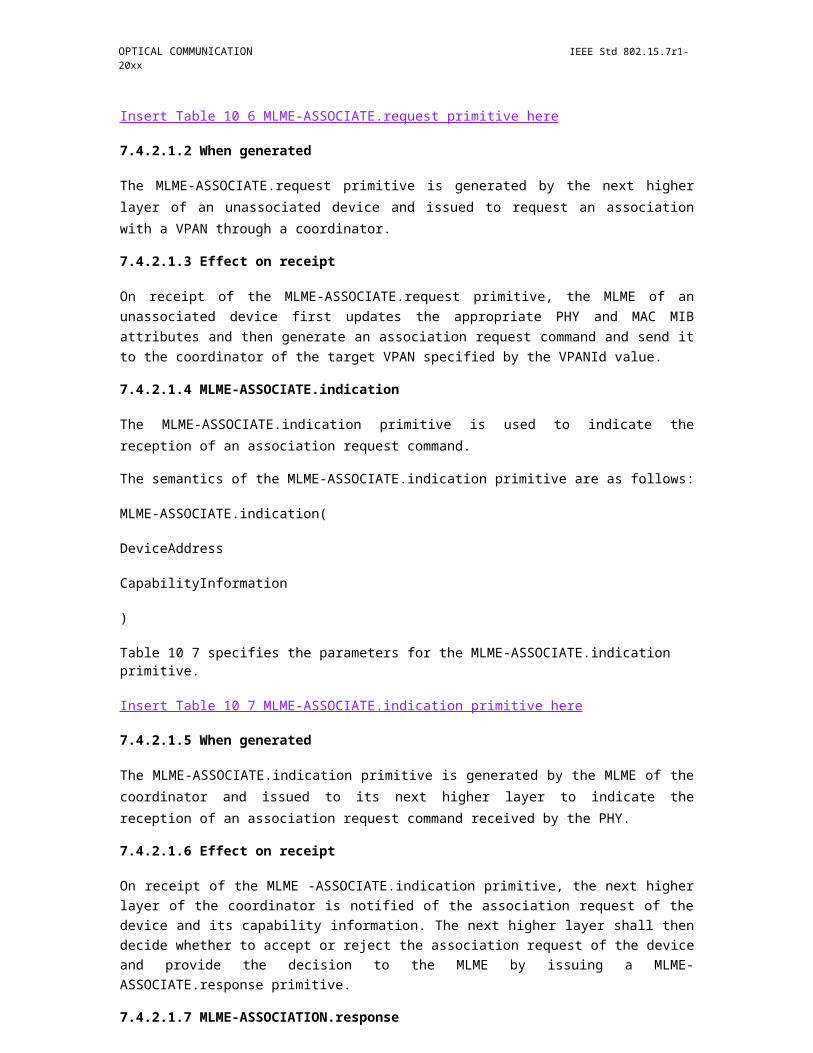
IEEE Std 802.15.7r1-20xx IEEE STANDARD FOR SHORT-RANGE WIRELESS
6.7.2.2.5.1 Function
This primitive is an indication by the PHY to the local MAC entity that the PHY layer has received a valid packet synchronization sequence and PHY header.
6.7.2.2.5.2 Semantics of the service primitive
The primitive provides the following parameter:
PHY-RXSTART.indicate (RXVECTOR)
The RXVECTOR represents a list of parameters that the PHY provides the local MAC entity upon receipt of a valid PHY header. This vector may contain both MAC and MAC management parameters. The required parameters are listed in Table 6.7.2.1.3.
6.7.2.2.5.3 When generated
This primitive is generated by the local PHY entity to the MAC sublayer when the PHY has successfully validated the PHY header at the start of a new PPDU.
6.7.2.2.5.4 Effect of receipt
The effect of receipt of this primitive by the MAC is unspecified.
6.7.2.2.6 PHY-RXEND.indicate
6.7.2.2.6.1 Function
532 Copyright © 20xx IEEE. All rights reserved.

OPTICAL COMMUNICATION IEEE Std 802.15.7r1-20xx
This primitive is an indication by the PHY to the local MAC entity that the MPDU currently being received is complete.
6.7.2.2.6.2 Semantics of the service primitive
The primitive provides the following parameter:
PHY-RXEND.indicate (RXERROR)
The RXERROR parameter can convey one or more of the following values: NoError, FormatViolation, or UnsupportedRate. A number of error conditions may occur after the PHY layer protocol has detected what appears to be a valid preamble and header. The following describes the parameter returned for each of those error conditions.
- NoError. This value is used to indicate that no error occurred during the receive process at the PHY layer.
- FormatViolation. This value is used to indicate that the format of the received PPDU was in error.
- UnsupportedRate. This value is used to indicate that during the reception of the incoming PPDU, a nonsupported date rate was detected.
6.7.2.2.6.3 When generated
This primitive is generated by the PHY for the local MAC entity to indicate that the receive state machine has completed a reception with or without errors. In the case of an RXERROR value of NoError, the MAC can use the PHY-RXEND.indicate as reference for channel access timing.
6.7.2.2.6.4 Effect of receipt
The effect of receipt of this primitive is for the MAC to begin inter-frame space processing if applicable.
6.7.2.2.7 PHY-SET-LOADING.request
Copyright © 2011 IEEE. All rights reserved. 533

IEEE Std 802.15.7r1-20xx IEEE STANDARD FOR SHORT-RANGE WIRELESS
6.7.2.2.7.1 Function
This primitive is a request by the MAC sublayer to the local PHY entity to update the bit loading scheme used for adaptive bit and energy loading.
6.7.2.2.7.2 Semantics of the service primitive
The primitive provides the following parameters:
PHY-SET-LOADING.request(BIT_LOADING_VECTOR)
The BIT_LOADING_ VECTOR represents a list of parameters that the MAC sublayer provides to the local PHY entity in order to set the energy and the constellation size on each data-bearing subcarrier in a SISO or MIMO configuration. This vector contains PHY management parameters. The required PHY parameters are listed in Table 6.7.2.1.3.
6.7.2.2.7.3 When generated
This primitive will be issued by the MAC sublayer to the PHY entity when the MAC sublayer needs to update the bit and energy allocation scheme.
6.7.2.2.7.4 Effect of receipt
The effect of receipt of this primitive by the PHY entity will be to update the bit and energy allocation scheme accordingly.
6.7.2.2.8 PHY-SET-LOADING.confirm
6.7.2.2.8.1 Function
This primitive is issued by the PHY to the local MAC entity to confirm the update of the bit and energy allo-cation scheme.
534 Copyright © 20xx IEEE. All rights reserved.

OPTICAL COMMUNICATION IEEE Std 802.15.7r1-20xx
6.7.2.2.8.2 Semantics of the service primitive
The semantics of the primitive are as follows:
PHY-SET-LOADING.confirm
This primitive has no parameters.
6.7.2.2.8.3 When generated
This primitive will be issued by the PHY to the MAC entity when the PHY has updated the bit and energy allocation scheme following the PHY-SET-LOADING.request by the MAC.
6.7.2.2.8.4 Effect of receipt
The receipt of this primitive by the MAC will cause the MAC to start the next MAC entity request.
6.7.2.2.9 PHY-PROVIDE-CSI.indicate
6.7.2.2.9.1 Function
This primitive is an indication by the PHY to the local MAC entity that the PHY layer has received a request to estimate the channel state information and has successfully completed the task.
6.7.2.2.9.2 Semantics of the service primitive
The primitive provides the following parameter:
PHY-PROVIDE-CSI.indicate (CSI_VECTOR)
Copyright © 2011 IEEE. All rights reserved. 535
IEEE Std 802.15.7r1-20xx IEEE STANDARD FOR SHORT-RANGE WIRELESS
The CSI_VECTOR represents a list of parameters that the PHY provides the local MAC entity upon receipt of a valid PHY header and successful estimation of the CSI. The required parameters are listed in Table 6.7.2.1.3.
6.7.2.2.9.3 When generated
This primitive is generated by the local PHY entity to the MAC sublayer when the PHY has successfully validated the PHY header at the start of a new PPDU and estimated the CSI.
6.7.2.2.9.4 Effect of receipt
The effect of receipt of this primitive by the MAC is unspecified.
17.2.6.3 PHY Data Service (move to 10.3)
17.2.6.3.1 PHY Data Service Primitives
Table 6.7.3.1.1. presents the PHY data service primitives.
Insert Table 6.7.3.1.1: PHY data service primitives.
Table 6.7.3.1.1. presents the PHY data service primitive parameters.
Insert Table 6.7.3.1.2: PHY data service primitive parameters.
17.2.6.3.2 Detailed PHY Data Service Specification
536 Copyright © 20xx IEEE. All rights reserved.

OPTICAL COMMUNICATION IEEE Std 802.15.7r1-20xx
6.7.3.2.1 PHY-DATA.request
6.7.3.2.1.1 Function
This primitive defines the transfer of an octet of data from the MAC sublayer to the local PHY entity.
6.7.3.2.1.2 Semantics of the service primitive
The primitive provides the following parameters:
PHY-DATA.request(DATA)
The DATA parameter is an octet of value X'00' through X'FF'.
6.7.3.2.1.3 When generated
This primitive is generated by the MAC sublayer to transfer an octet of data to the PHY entity. This
primitive can only be issued following a transmit initialization response (PHY-TXSTART.confirm) from the PHY.
6.7.3.2.1.4 Effect of receipt
The receipt of this primitive by the PHY entity causes the PHY to transmit an octet of data. When the PHY entity receives the octet, it will issue a PHY-DATA.confirm to the MAC sublayer.
6.7.3.2.2 PHY-DATA.indicate
6.7.3.2.2.1 Function
Copyright © 2011 IEEE. All rights reserved. 537

IEEE Std 802.15.7r1-20xx IEEE STANDARD FOR SHORT-RANGE WIRELESS
This primitive indicates the transfer of data from the PHY to the local MAC entity.
6.7.3.2.2.2 Semantics of the service primitive
The primitive provides the following parameters:
PHY-DATA.indicate (DATA)
The DATA parameter is an octet of value X'00' through X'FF'.
6.7.3.2.2.3 When generated
The PHY-DATA.indication is generated by a receiving PHY entity to transfer the received octet of data to the local MAC entity.
6.7.3.2.2.4 Effect of receipt
The effect of receipt of this primitive by the MAC is unspecified.
6.7.3.2.3 PHY-DATA.confirm
6.7.3.2.3.1 Function
This primitive is issued by the PHY to the local MAC entity to confirm the transfer of data from the MAC entity to the PHY.
6.7.3.2.3.2 Semantics of the service primitive
538 Copyright © 20xx IEEE. All rights reserved.

OPTICAL COMMUNICATION IEEE Std 802.15.7r1-20xx
The semantics of the primitive are as follows:
PHY-DATA.confirm
This primitive has no parameters.
6.7.3.2.3.3 When generated
This primitive will be issued by the PHY to the MAC entity when the PHY has completed the transfer of data from the MAC entity. The PHY will issue this primitive in response to every PHY-DATA.request prim-itive issued by the MAC sublayer.
6.7.3.2.3.4 Effect of receipt
The receipt of this primitive by the MAC will cause the MAC to start the next MAC entity request.
6.7.3.2.4 PHY-MAC-HEADER.request
6.7.3.2.4.1 Function
This primitive defines the transfer of the high-reliability MAC header information from the MAC sublayer to the local PHY entity.
6.7.3.2.4.2 Semantics of the service primitive
The primitive provides the following parameters:
PHY-MAC-HEADER.request(MAC_HEADER)
Copyright © 2011 IEEE. All rights reserved. 539

IEEE Std 802.15.7r1-20xx IEEE STANDARD FOR SHORT-RANGE WIRELESS
The MAC_HEADER parameter is six octets containing the information described in subclause 6.2.5.1.
6.7.3.2.4.3 When generated
This primitive is generated by the MAC sublayer to transfer an octet of data to the PHY entity. This
primitive can only be issued following a transmit initialization response (PHY-TXSTART.confirm) from the PHY.
6.7.3.2.4.4 Effect of receipt
The receipt of this primitive by the PHY entity causes the PHY to transmit the high-reliability MAC header data. When the PHY entity receives these six octets, it will issue a PHY-MAC-HEADER.confirm to the MAC sublayer.
6.7.3.2.5 PHY-MAC-HEADER.indicate
6.7.3.2.5.1 Function
This primitive indicates the transfer of the high-reliability MAC header information from the PHY to the local MAC entity.
6.7.3.2.5.2 Semantics of the service primitive
The primitive provides the following parameters:
PHY-MAC-HEADER.indicate (MAC_HEADER)
The MAC_HEADER parameter is six octets containing the information described in subclause 6.2.5.1.
540 Copyright © 20xx IEEE. All rights reserved.
OPTICAL COMMUNICATION IEEE Std 802.15.7r1-20xx
6.7.3.2.5.3 When generated
The PHY-MAC-HEADER.indication is generated by a receiving PHY entity to transfer the received six octets of the high-reliability MAC header to the local MAC entity.
6.7.3.2.5.4 Effect of receipt
The effect of receipt of this primitive by the MAC is unspecified.
6.7.3.2.6 PHY-MAC-HEADER.confirm
6.7.3.2.6.1 Function
This primitive is issued by the PHY to the local MAC entity to confirm the transfer of the high-reliability MAC header information from the MAC entity to the PHY.
6.7.3.2.6.2 Semantics of the service primitive
The semantics of the primitive are as follows:
PHY-MAC-HEADER.confirm
This primitive has no parameters.
6.7.3.2.6.3 When generated
Copyright © 2011 IEEE. All rights reserved. 541
IEEE Std 802.15.7r1-20xx IEEE STANDARD FOR SHORT-RANGE WIRELESS
This primitive will be issued by the PHY to the MAC entity when the PHY has completed the transfer of the high-reliability MAC header information from the MAC entity. The PHY will issue this primitive in response to every PHY-MAC-HEADER.request primitive issued by the MAC sublayer.
6.7.3.2.6.4 Effect of receipt
The receipt of this primitive by the MAC will cause the MAC to start the next MAC entity request.
542 Copyright © 20xx IEEE. All rights reserved.
OPTICAL COMMUNICATION IEEE Std 802.15.7r1-20xx
Annex A
(informative)
Bibliography
A.1 General
Bibliographical references are resources that provide additional or helpful material but do not need to be understood or used to implement this standard. Reference to these resources is made for informational use only.
[B1] Berman, S. M., Greenhouse, D. S., Bailey, I. L., Clear, R. and Raasch, T. W., “Human electroretinogram responses to video displays, fluorescent lighting and other high frequency sources,” Optometry and Vision Science 68:645–662, 1991.
[B2] CIE (1932) Commission internationale de l'Eclairage proceedings, 1931. Cambridge University Press, Cambridge.
[B3] Colman, R. S., Frankel, F., Ritvo, E., and Freeman, B., “The effects of fluorescent and incandescent illumination upon repetitive behaviors in autistic children,” J. Autism Childhood Schz. 6:157–162, 1976.
[B4] Harding, G. F. A. and Jeavons, P., “Photosensitive Epilepsy,” Mac Keith Press, 1994.
[B5] IEEE 802.15 document 15-10-0151-01-0007, “High-power high-bandwidth linear driving circuit for VLC applications,” Baumgartner, Robert, et. al., https://mentor.ieee.org/802.15/dcn/10/15-10-0151-01-0007-high-power-high-bandwidth-linear-driving-circuit-for-vlc-applications.pdf.
[B6] IEEE Std 802.11TM-2007, Information technology—Telecommunications and information exchange between systems—Local and metropolitan area networks—Specific requirements—Part 11: Wireless LAN Medium Access Control (MAC) and Physical Layer (PHY) Specifications.
[B7] IEEE Std 802.15.3TM-2003, IEEE Standard for Information technology—Telecommunications and information exchange between systems—Local and metropolitan area networks—Specific requirements— Part 15.3: Wireless Medium Access Control (MAC) and Physical Layer (PHY) Specifications for High Rate Wireless Personal Area Networks (VPANs).
[B8] ISO/IEC 7498-1:1994, Information technology—Open Systems Interconnection—Basic Reference
Model: The Basic Model.9
[B9] Kang, T. G., et. al., “White Paper: IEEE 802.15.7 VLC Regulations,” July 2010, IEEE802.15 contribution 15-10-0615-01-0007, https://mentor.ieee.org/802.15/dcn/10/15-10-0615-01-0007-white-paper-ieee-802-15-7-vlc-regulations.pdf.
[B10] Küller, R. and Laike, T., “The impact of flicker from fluorescent lighting on well-being, performance, and physiological arousal,” Ergonomics 41(4): 433–447, 1998.
[B11] Lindner, H. and Kropf, S., “Asthenopic complaints associated with fluorescent lamp illumination (FLI): The role of individual disposition,” Lighting Res. Technol. Vol. 25:59–69, 1993.
9ISO publications are available from the ISO Central Secretariat, Case Postale 56, 1 rue de Varembé, CH-1211, Genève 20, Switzerland/Suisse (http://www.iso.ch/). ISO publications are also available in the United States from the Sales Department, American National Standards Institute, 25 West 43rd Street, 4th Floor, New York, NY 10036, USA (http://www.ansi.org/).
Copyright © 2011 IEEE. All rights reserved. 543
IEEE Std 802.15.7r1-20xx IEEE STANDARD FOR SHORT-RANGE WIRELESS
[B12] Schubert, E. Fred, “Light Emitting Diodes,” Cambridge University Press, 2003.
[B13] Stone, P. T., “Fluorescent lighting and health,” Lighting Res. Technol. 24:55–61, 1990.
[B14] Walewski, J. W., “Color stabilization for CSK by use of visibility frames,” January 2011, IEEE802.15 contribution 15-1-0262-05-0007, https://mentor.ieee.org/802.15/dcn/11/15-10-0262-05-0007-color-stabilization-for-csk-by-use-of-visibility-frames.pdf.
[B15] Wilkins, A. J., I. Nimmo-Smith, A. Slater, and L. Bedocs, “Fluorescent lighting headaches and eye-strain,” Lighting Res. Technol. Vol. 21:11–18, 1989.
[B16] Wright, P. S., “An overview of harmonic and flicker emission standards and their associated measurements,” Power Eng. J. 15(2): 87–93, 2001.
[B17] Yokoi, A., et. al., “More description about CSK constellation,” March 2011, IEEE 802.15 contribution 15-11-0247-00-0007, https://mentor.ieee.org/802.15/dcn/11/15-11-0247-00-0007-csk-constellation-in-all-color-band-combinations.pdf.
A.2 Regulatory documents
[B18] ANSI C82.77-2002, American National Standard for Harmonic Emission Limits—Related Power
Quality Requirements for Lighting Equipment.10
[B19] ANSI C82.SSL1 Operational Characteristics and Electrical Safety of SSL Power Supplies and Drivers.
[B20] ANSI Z136.1, American National Standard for Safe Use of Lasers (2007).
[B21] ANSI Z136.6, American National Standard for Safe Use of Lasers Outdoors (2005).
[B22] ARIB STD-T66, Second Generation Low Power Data Communication System/Wireless LAN
System 1999.12.14 (H11.12.14) Version 1.0.11
[B23] BS EN 29241-3:1993, Ergonomic requirements for office work with visual display terminals (VDTs). Visual display requirements.
[B24] EN61000 -3-3: Electronic compatibility (EMC) Part 3: Limits—Section 3: Limitation of voltage fluctuations and flicker in low voltage supply systems for equipment with rated current 16 A and smaller. International Electrotechnical Commission, 1994.
[B25] ERC Recommendation 70-03, Relating to the Use of Short Range Devices (SRDs), April 2002.12
[B26] IEC 1000-3-3 (1994), Part 3: Limits—Section 3: Limitation of voltage fluctuations and flicker in low-voltage supply systems for equipment with rated current 16 A.
[B27] IEC 1000-3-5: Electromagnetic compatibility. Part 3: Limits—Section 5: Limitation of voltage fluctuations and flicker in low-voltage power supply systems for equipment with rated current greater than 16 A. 1994.
10ANSI C82 publications are available from NEMA publications are available from the National Electrical Manufacturers Association, 1300 N. 17th St., Ste. 1847, Rosslyn, VA 22209, USA.11ARIB publications are available from the Association of Radio Industries and Businesses (http://www.arib.or.jp).12ERC publications are available from Global Engineering Documents, 15 Inverness Way East, Englewood, Colorado 80112, USA (http://global.ihs.com/).
544 Copyright © 20xx IEEE. All rights reserved.
OPTICAL COMMUNICATION IEEE Std 802.15.7r1-20xx
[B28] IEC 60050-112 ed1.0 (2010-01) TC/SC 1—International Electrotechnical Vocabulary—Part 112: Quantities and units.
[B29] IEC 60050-300 ed1.0 (2001-07), International Electrotechnical Vocabulary—Electrical and electronic measurements and measuring instruments—Part 311: General terms relating to measurements—Part 312: General terms relating to electrical measurements—Part 313: Types of electrical measuring instruments— Part 314: Specific terms according to the type of instrument.
[B30] IEC 60050-845 ed1.0 (1987-12), International Electrotechnical Vocabulary, Lighting.
[B31] IEC 60825-1 ed2.0 (2007-03), Safety of laser products—Part 1: Equipment classification and requirements.
[B32] IEC 60825-12 ed1.0 (2004-02), Safety of laser products—Part 12: Safety of free space optical communication systems used for transmission of information.
[B33] IEC 61347-1 ed2.0 (2007-01), Lamp control gear—Part 1: General and safety requirements.
[B34] IEC 61347-2-13 ed1.0 (2006 -05), Lamp control gear—Part 2-13: Particular requirements for d.c. or a.c. supplied electronic control gear for LED modules
[B35] IEC 62384-am1 ed1.0 (2009-07) Amendment 1—DC or AC supplied electronic control gear for LED modules—Performance requirements.
[B36] IEC 62471 ed1.0 (2006-07), Photobiological safety of lamps and lamp systems.
[B37] IEC/TR 62471-2 ed1.0 (2009-08), Photobiological safety of lamps and lamp systems—Part 2: Guidance on manufacturing requirements relating to non-laser optical radiation safety.
[B38] IEC/TS 61000-3-5 Ed. 2.0 b Cor.2:2010 Corrigendum 2—Electromagnetic compatibility (EMC)— Part 3-5: Limits—Limitation of voltage fluctuations and flicker in low-voltage power supply systems for equipment with rated current greater than 75 A.
[B39] ANSI/IESNA RP-16-05, Nomenclature and Definitions for Illuminating Engineering.13
[B40] ANSI/IESNA RP-27.1-05, Photobiological Safety for Lamps and Lamp Systems—General Requirements.
[B41] IESNA LM-79-08, IES Approved Method for the Electrical and Photometric Measurements of Solid-State Lighting Products.
[B42] IESNA LM-80-08, IES Approved Method: Measuring Lumen Maintenance of LED Light Sources.
[B43] IESNA TM-16-05, Technical Memorandum on Light Emitting Diode (LED) Sources and Systems.
[B44] Recommendation ITU-R RA.1630, Technical and operational characteristics of ground-based astronomy systems for use in sharing studies with active services between 10 THz and 1000 THz.
[B45] Recommendation ITU-R RS.1744, Technical and operational characteristics of ground-based
meteorological aids systems operating in the frequency range 272–750 THz.14
13IESNA is the Illuminating Engineering Society Standards from ANSI. IESNA publications are available from the Sales Department, American National Standards Institute, 25 West 43rd Street, 4th Floor, New York, NY 10036, USA (http://www.ansi.org/).14This recommendation replaces ITU-R SA.1744. ITU-T publications are available from the International Telecommunications Union, Place des Nations, CH-1211, Geneva 20, Switzerland/Suisse (http://www.itu.int/).
Copyright © 2011 IEEE. All rights reserved. 545
IEEE Std 802.15.7r1-20xx IEEE STANDARD FOR SHORT-RANGE WIRELESS
Annex B
(normative)
Service-specific convergence sublayer (SSCS)
B.1 IEEE 802.2 convergence sublayer
The IEEE 802.2 convergence sublayer exists above the IEEE 802.15.7 MCPS. This sublayer provides an interface between an instance of an IEEE 802.2 LLC sublayer and the IEEE 802.15.7 MCPS.
B.1.1 MA-UNITDATA.request
The MA-UNITDATA.request primitive requests the transfer of a LLC protocol data unit (LPDU) (i.e., MSDU) from a local IEEE 802.2 Type 1 LLC sublayer entity to a single peer IEEE 802.2 Type 1 LLC sublayer entity or multiple peer IEEE 802.2 Type 1 LLC sublayer entities in the case of a group address.
The semantics of the MA-UNITDATA.request primitive is as follows:
MA-UNITDATA.request (SrcAddr,DstAddr,RoutingInformation,data,priority,ServiceClass)
Table B.1 specifies the parameters for the MA-UNITDATA.request primitive.
Table B.1—MA-UNITDATA.request parameters
Name Type Valid range Description
SrcAddr IEEE Any valid The individual IEEE address of the entity from which theaddress IEEE address MSDU is being transferred.
DstAddr IEEE Any valid The individual IEEE address of the entity to which theaddress IEEE address MSDU is being transferred.
RoutingInformation — null This parameter is not used by the MAC sublayer and shall bespecified as a null value.
data Set of — The set of octets forming the MSDU to be transmitted by theoctets MAC sublayer entity.
priority — null This parameter is not used by the MAC sublayer and shall bespecified as a null value.
ServiceClass — null This parameter is not used by the MAC sublayer and shall bespecified as a null value.
546 Copyright © 20xx IEEE. All rights reserved.
OPTICAL COMMUNICATION IEEE Std 802.15.7r1-20xx
B.1.1.1 Appropriate usage
The MA-UNITDATA.request primitive is generated by a local IEEE 802.2 Type 1 LLC sublayer entity when an LPDU (MSDU) is to be transferred to a peer IEEE 802.2 Type 1 LLC sublayer entity or entities.
B.1.1.2 Effect on receipt
On receipt of the MA-UNITDATA.request primitive, the MAC sublayer entity shall begin the transmission of the supplied MSDU.
The MAC sublayer first builds an MPDU to transmit from the supplied arguments. The MPDU shall be transmitted using the unslotted CSMA-CA algorithm in the contention period of the frame and without requesting a handshake.
If the unslotted CSMA-CA algorithm indicates a busy channel, the MAC sublayer shall issue the MA-UNITDATA-STATUS.indication primitive with a status of CHANNEL_ACCESS_FAILURE. If the MPDU was successfully transmitted, the MAC sublayer shall issue the MA-UNITDATA-STATUS.indication primitive with a status of SUCCESS.
B.1.2 MA-UNITDATA.indication
The MA -UNITDATA.indication primitive indicates the transfer of an LPDU (i.e., MSDU) from the MAC sublayer to the local IEEE 802.2 Type 1 LLC sublayer entity.
The semantics of the MA-UNITDATA.indication primitive is as follows:
MA-UNITDATA.indication (SrcAddr,DstAddr,RoutingInformation,data,ReceptionStatus,priority,ServiceClass)
Table B.2 specifies the parameters for the MA-UNITDATA.indication primitive.
Table B.2—MA-UNITDATA.indication parameters
Name Type Valid range Description
SrcAddr IEEE Any valid The individual IEEE address of the entity from whichaddress IEEE address the MSDU has been received.
DstAddr IEEE Any valid The individual IEEE address of the entity to which theaddress IEEE address MSDU is being transferred.
RoutingInformation — null This parameter is not used by the MAC sublayer andshall be specified as a null value.
Copyright © 2011 IEEE. All rights reserved. 547
IEEE Std 802.15.7r1-20xx IEEE STANDARD FOR SHORT-RANGE WIRELESS
Table B.2—MA-UNITDATA.indication parameters (continued)
Name Type Valid range Description
data Set of octets — The set of octets forming the MSDU received by theMAC sublayer entity.
ReceptionStatus — null This parameter is not used by the MAC sublayer andshall be specified as a null value.
priority — null This parameter is not used by the MAC sublayer andshall be specified as a null value.
ServiceClass — null This parameter is not used by the MAC sublayer andshall be specified as a null value.
B.1.2.1 When generated
On receipt of a data frame at the local MAC sublayer entity, the FCS field is checked. If it is valid, the MAC sublayer shall issue the MA-UNITDATA.indication primitive to the IEEE 802.2 Type 1 LLC sublayer entity, indicating the arrival of a MSDU. If the FCS is not valid, the frame shall be discarded, and the IEEE 802.2 Type 1 LLC sublayer entity shall not be informed.
B.1.2.2 Appropriate usage
The appropriate usage of the MA-UNITDATA.indication primitive by the IEEE 802.2 Type 1 LLC sublayer entity is not specified in this standard.
B.1.3 MA-UNITDATA-STATUS.indication
The MA-UNITDATA-STATUS.indication primitive reports the results of a request to transfer a LPDU (MSDU) from a local IEEE 802.2 Type 1 LLC sublayer entity to a single peer IEEE 802.2 Type 1 LLC sublayer entity or to multiple peer IEEE 802.2 Type 1 LLC sublayer entities.
The semantics of the MA-UNITDATA-STATUS.indication primitive is as follows:
MA-UNITDATA-STATUS.indication ( SrcAddr, DstAddr, status,
ProvPriority, ProvServiceClass)
Table B.3 specifies the parameters for the MA-UNITDATA-STATUS.indication primitive.
B.1.3.1 When generated
The MA-UNITDATA-STATUS.indication primitive is generated by the MAC sublayer entity in response to an MA-UNITDATA.request primitive issued by the IEEE 802.2 Type 1 LLC sublayer.
548 Copyright © 20xx IEEE. All rights reserved.

OPTICAL COMMUNICATION IEEE Std 802.15.7r1-20xx
Table B.3—MA-UNITDATA-STATUS.indication parameters
Name Type Valid Range Description
SrcAddr IEEE Any valid IEEE address The individual IEEE address of theaddress entity from which the MSDU has been
transferred.
DstAddr IEEE Any valid IEEE address The individual IEEE address of theaddress entity to which the MSDU has been
transferred.
status Enumeration SUCCESS, TRANSMIS- The status of the last MSDUSION_PENDING, NO_BEACON, transmission.or CHANNEL_ACCESS_FAIL-URE
ProvPriority — null This parameter is not used by the MACsublayer and shall be specified as anull value.
ProvServiceClass — null This parameter is not used by the MACsublayer and shall be specified as anull value.
B.1.3.2 Appropriate usage
The receipt of the MA-UNITDATA-STATUS.indication primitive by the IEEE 802.2 Type 1 LLC sublayer entity signals the completion of the current data transmission.
Copyright © 2011 IEEE. All rights reserved. 549
IEEE Std 802.15.7r1-20xx IEEE STANDARD FOR SHORT-RANGE WIRELESS
Annex C
(normative)
Cyclic redundancy check
The CRC field is 2 octets in length. The CRC shall be calculated using the following standard generator polynomial of degree 16:
G16x = x16 + x12 + x5 + 1 (C.1)
The CRC shall be calculated for transmission using the following algorithm:
— Let Mx = b0xk – 1 + b1xk – 2 + + bk – 2x + bk – 1 be the polynomial representing the sequence of bits for which the checksum is to be computed.
— Multiply M(x) by x16, giving the polynomial x16 Mx .— Divide x16 Mx modulo 2 by the generator polynomial, G16(x), to obtain the remainder
polynomial, Rx = r0x15 + r1x14 + + r14x + r15 .— The CRC field is given by the coefficients of the remainder polynomial, R(x).
Here, binary polynomials are represented as bit strings, in highest polynomial degree first
order. A typical implementation is depicted in Figure C.1.
CRC-16 Generator Polynomial: G(x) = x16 + x12 + x5 + 1
InputData Field (LSB first)
1. Initialize the remainder register (r0 through r15) to all ones.
2. Shift the data into the divider in the order of transmission (LSB).
3. After the last bit of the data field is shifted into the divider,the remainder register contains the CRC.
4. The CRC is appended to the data so that r0 is transmitted first.
Figure C.1—Typical CRC implementation
550 Copyright © 20xx IEEE. All rights reserved.
OPTICAL COMMUNICATION IEEE Std 802.15.7r1-20xx
Annex D
(normative)
Channel assignment
Table D.1 shows the bit patterns that are used to assign multiple channels for VLC.
Table legend: X=not used and O=used
Table D.1—Multiple channel assignment table
Bit Band 1 Band 2 Band 3 Band 4 Band 5 Band 6 Band 7
0000000 No multiple channel mode
0000001 X X X X X X O
0000010 X X X X X O X
0000011 X X X X X O O
0000100 X X X X O X X
0000101 X X X X O X O
0000110 X X X X O O X
0000111 X X X X O O O
0001000 X X X O X X X
0001001 X X X O X X O
0001010 X X X O X O X
0001011 X X X O X O O
0001100 X X X O O X X
0001101 X X X O O X O
0001110 X X X O O O X
0001111 X X X O O O O
0010000 X X O X X X X
0010001 X X O X X X O
0010010 X X O X X O X
0010011 X X O X X O O
0010100 X X O X O X X
0010101 X X O X O X O
0010110 X X O X O O X
0010111 X X O X O O O
0011000 X X O O X X X
Copyright © 2011 IEEE. All rights reserved. 551

IEEE Std 802.15.7r1-20xx IEEE STANDARD FOR SHORT-RANGE WIRELESS
Table D.1—Multiple channel assignment table (continued)
Bit Band 1 Band 2 Band 3 Band 4 Band 5 Band 6 Band 7
0011001 X X O O X X O
0011010 X X O O X O X
0011011 X X O O X O O
0011100 X X O O O X X
0011101 X X O O O X O
0011110 X X O O O O X
0011111 X X O O O O O
0100000 X O X X X X X
0100001 X O X X X X O
0100010 X O X X X O X
0100011 X O X X X O O
0100100 X O X X O X X
0100101 X O X X O X O
0100110 X O X X O O X
0100111 X O X X O O O
0101000 X O X O X X X
0101001 X O X O X X O
0101010 X O X O X O X
0101011 X O X O X O O
0101100 X O X O O X X
0101101 X O X O O X O
0101110 X O X O O X O
0101111 X O X O O O X
0110000 X O O X X X X
0110001 X O O X X X O
0110010 X O O X X O X
0110011 X O O X X O O
0110100 X O O X O X X
0110101 X O O X O X O
0110110 X O O X O O X
0110111 X O O X O O O
0111000 X O O O X X X
0111001 X O O O X X X
552 Copyright © 20xx IEEE. All rights reserved.
OPTICAL COMMUNICATION IEEE Std 802.15.7r1-20xx
Table D.1—Multiple channel assignment table (continued)
Bit Band 1 Band 2 Band 3 Band 4 Band 5 Band 6 Band 7
0111010 X O O O X X X
0111011 X O O O X X X
0111100 X O O O O X X
0111101 X O O O O X X
0111110 X O O O O O X
0111111 X O O O O O O
1000000 O X X X X X X
1000001 O X X X X X O
1000010 O X X X X O X
1000011 O X X X X O O
1000100 O X X X O X X
1000101 O X X X O X O
1000110 O X X X O O X
1000111 O X X X O O O
1001000 O X X O X X X
1001001 O X X O X X O
1001010 O X X O X O X
1001011 O X X O X O O
1001100 O X X O O X X
1001101 O X X O O X O
1001110 O X X O O O X
1001111 O X X O O O O
1010000 O X O X X X X
1010001 O X O X X X O
1010010 O X O X X O X
1010011 O X O X X O O
1010100 O X O X O X X
1010101 O X O X O X O
1010110 O X O X O O X
1010111 O X O X O O O
1011000 O X O O X X X
1011001 O X O O X X O
1011010 O X O O X O X
Copyright © 2011 IEEE. All rights reserved. 553
IEEE Std 802.15.7r1-20xx IEEE STANDARD FOR SHORT-RANGE WIRELESS
Table D.1—Multiple channel assignment table (continued)
Bit Band 1 Band 2 Band 3 Band 4 Band 5 Band 6 Band 7
1011011 O X O O X O O
1011100 O X O O O X X
1011101 O X O O O X O
1011110 O X O O O O X
1011111 O X O O O O O
1100000 O O X X X X X
1100001 O O X X X X O
1100010 O O X X X O X
1100011 O O X X X O O
1100100 O O X X O X X
1100101 O O X X O X O
1100110 O O X X O O X
1100111 O O X X O O O
1101000 O O X O X X X
1101001 O O X O X X O
1101010 O O X O X O X
1101011 O O X O X O O
1101100 O O X O O X X
1101101 O O X O O X O
1101110 O O X O O O X
1101111 O O X O O O O
1110000 O O O X X X X
1110001 O O O X X X O
1110010 O O O X X O X
1110011 O O O X X O O
1110100 O O O X O X X
11101001 O O O X O X O
1110110 O O O X O O X
1110111 O O O X O O O
1111000 O O O O X X X
1111001 O O O O X X O
1111010 O O O O X O X
1111011 O O O O X O O
554 Copyright © 20xx IEEE. All rights reserved.
OPTICAL COMMUNICATION IEEE Std 802.15.7r1-20xx
Table D.1—Multiple channel assignment table (continued)
Bit Band 1 Band 2 Band 3 Band 4 Band 5 Band 6 Band 7
1111100 O O O O O X X
1111101 O O O O O X O
1111110 O O O O O O X
1111111 O O O O O O O
An example is shown in Figure D.1 where it is assumed that red, green and blue are available at the optical sources. If a certain optical source uses HP1 (00001) and another optical source in the adjacent cell uses HP2 (00011), then hopping pattern application in the adjacent cell is that HP1 operates R in first frame or time slot, B in second frame or time slot, G in third frame or time slot, but HP2 is operating at G in first frame or time slot, G and R in second frame or time slot, R and B in third frame or time slot. This mechanism can avoid interference between optical sources. Also the hopping pattern application is not limited to one frame or one time slot. A hopping pattern across multiple frames or time slots is fine.
Table D.2 shows a hopping pattern example applicable to VLC. If coordinator assign pattern '00001' to a device by using H_pattern, then the device’s frame or time slot moves according to the hopping pattern. Also one hopping pattern or multiple hopping patterns can be assigned to one user.
Figure D.1—Hopping pattern assignment
Copyright © 2011 IEEE. All rights reserved. 555
IEEE Std 802.15.7r1-20xx IEEE STANDARD FOR SHORT-RANGE WIRELESS
Table D.2—Example of hopping pattern assignment
Pattern 00001 00011 00101
Frame/time slot HP1 HP2 HP3
1 R G B
2 B G/R B
3 G R/B G
4 G/R B G/R
5 G/R R G/B
6 R/B G R/B
7 G B R
8 B R G
9 R G/B R
556 Copyright © 20xx IEEE. All rights reserved.

OPTICAL COMMUNICATION IEEE Std 802.15.7r1-20xx
Annex E
(informative)
Considerations for VLC using LED displays
E.1 Introduction—Dynamic displays vs. addressed displays
This annex discusses two types of LED involved displays: dynamic displays and addressed displays. The fundamental different between the two has to do with the amount of time the pixel is illuminated. In dynamic displays the pixels on a line are illuminated once every frame for T_ frame/N_line seconds where N_line is the number of lines controlled by a line scan controller and T_frame is the time to sweep N_line once; that is, the pixels on a line are operated dynamically so that they are only on for a fraction of the total frame time (hence the name “dynamic”). In the addressed display, the pixel is illuminated for the duration of the frame and is readdressed once per frame for possible state change.
E.2 Dynamic displays
E.2.1 Operation mechanism
In general, a dynamic display consists of a host controller, a line scan controller, a display data buffer, and LED matrix, as shown in Figure E.1. The line scan controller selects a line for display, and the display data buffer transmits state information, such as the on/off state or the color selection, to each LED pixel on the selected line. The line scan controller determines the active time of each line, where the active time indicates whether the LED pixels on the selected line are switched ON or OFF as per the display data buffer for the active time of the selected line. Therefore, VLC using a dynamic display is tightly coupled with the active time.
Figure E.1—General architecture of LED signboard operated by the dynamic display mechanism
Copyright © 2011 IEEE. All rights reserved. 557

IEEE Std 802.15.7r1-20xx IEEE STANDARD FOR SHORT-RANGE WIRELESS
It is well known that most of PC monitors and TV display images use 60 displayed-frames per second. In the case of PC monitors or TVs, the total displayed-frame number (i.e., different display information) is actually 30 frames per second because each displayed-frame is transmitted twice. The display mechanism of a dynamic display is similar to a PC monitor or TV. Assuming that a dynamic display consists of 16x16 lines and displays images or text through 60 displayed-frames per second, with 16 lines per displayed-frame, the active time slot period for VLC assigned to each line is 1.042 ms per displayed-frame, as shown in Figure E.2. Therefore, an active time slot can transmit 130 byte at 1 Mbit/s, as shown in Figure E.3.
1 display frame time = 1/60 sec
line 1
line 2
• 1.042ms •• •• •
line 16
active time per display -frame per line = (1/60)/16 sec
Figure E.2—Operation mechanism of dynamic display
line 1 slot 1 slot 1
line 2 slot 2 slot 2
••
header data 130 bytes••• •
••
line 16 slot 16
Figure E.3—An example of VLC data transmission on a dynamic display
E.2.2 Reduced brightness mitigation on VLC dynamic displays
The VLC dynamic display may be less bright than the non-VLC dynamic display because of the VLC modulation during the active time periods. Therefore, it is important to minimize the reduction of the average brightness of the dynamic display during the shortest time period that the human can distinguish.
558 Copyright © 20xx IEEE. All rights reserved.

OPTICAL COMMUNICATION IEEE Std 802.15.7r1-20xx
This is done to keep the display performing adequately for its intended function. Figure E.4 shows an example of an operational mechanism to mitigate the average brightness reduction per display frame time that can arise for a dynamic display having 16x16 lines operating as shown in Figure E.2 (i.e., the VLC data is carried during the active time of each line). The average brightness per display frame time in Figure E.4 is twice as large as that in Figure E.2 because the active time is twice as long.
1 frame time = 1/60 sec
line 1 slot 1 slot 1
line 2 slot 2 • • • slot 2
header data 260 bytes
••
•
line 8 slot 8
line 9 slot 1 slot 1
line 10 slot 2 • • • slot 2
header data 260 bytes
••
•
line 16 slot 8
active time per display -frame per line = (1/60)/8 sec
Figure E.4—An example for the mitigation of the average brightness reduction on the VLC dynamic display
E.2.3 VLC application using dynamic displays
A VLC enabled dynamic display can be used in the broadcast topology. The VLC broadcast topology in this standard consists of mainly the beacon and the downlink, as shown in Figure 56. Therefore, the VLC broadcast topology using a dynamic display can be constructed by the assignment of the active time slots and the use of GTS field in the beacon frame. Figure E.5 shows the VLC broadcast topology construction using the dynamic display. The active time slot #1 is assigned to the beacon and the active time slots from #2 to #8 are assigned to the downlink in Figure E.5. The GTS fields of the beacon frame can be used to indicate the GTS number, GTS length, and GTS direction for the broadcast topology. Multiple GTS slots can also be used depending upon the desired service level, the subscriber's grade, and the QoS policy.
Copyright © 2011 IEEE. All rights reserved. 559
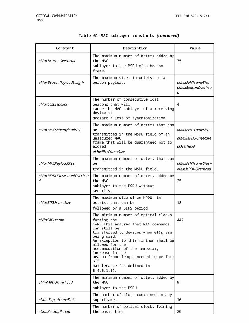
IEEE Std 802.15.7r1-20xx IEEE STANDARD FOR SHORT-RANGE WIRELESS
CFP
line 1 beacon beacon
line 2 GTS #1 GTS #1
GTS #2 GTS #2•••• •• •
•GTS #7
line 9 beacon beacon
line 10 GTS #1 GTS #1
•• •• •
•line 16 GTS #7
Figure E.5—VLC broadcast topology construction using the dynamic display
E.3 Addressed displays
In an addressed display a particular pixel is addressed (i.e., refreshed) once every frame; that is, once addressed the pixel maintains its current state until readdressed during the next frame. The role of the LED can be either to provide pixel back lighting, as in the case of an LCD (liquid crystal display), or the pixel can be formed directly from a LED device as in the case of LED signage (which would typically be implemented as a pixel constructed from a compound RGB LED). Generally the addressed pixels in a frame are serially updated and there is no need for a retrace blanking interval as in the old days of cathode ray tubes.
E.3.1 LCD display using LED backlighting modulation
In LED backlighting, there are numerous LEDs that provide illuminance for all LCD pixels, while the intensity of a particular pixel is determined by the transmittance of the pixel LCD. This means the data modulation of the LED backlighting is going to radiate from all the pixels. The radiation is a density (mW/ unit area) and the best performance occurs when the sensor views the whole screen (i.e., ingests the most power). Viewing the whole screen also provides intensity averaging over all the pixels, which is advantageous since in the some scenes various pixels might go dark. Given enough area averaging, there no particular relationship between the data rate and the frame refresh rate.
E.3.2 LED pixel modulation
One has the option of either modulating individual pixels or groups of pixels. In other words, one can generate at least two display sections that can transmit different data. One could even go further and create intermediate sections that transmit an aggregate of the data transmitted in the adjacent sections. For this to
560 Copyright © 20xx IEEE. All rights reserved.
OPTICAL COMMUNICATION IEEE Std 802.15.7r1-20xx
work one needs a detector capable of spatially resolving such sections. Partitioning of the display is done by using the cell mechanism and the PHY SAP, which were introduced for mobility support (see 6.2.11). For example, the cell partitioning in Figure 79 can be interpreted as a 2x2 display with four sections if the transmitters are operated in the broadcast mode. Also, wavelength division multiplexing of RGB pixels can be enabled with this mechanism, so that each color carries a different data stream. Averaging over an area of the sign allows some insensitivity to scene-to-scene pixel intensity variation.
Copyright © 2011 IEEE. All rights reserved. 561

IEEE Std 802.15.7r1-20xx IEEE STANDARD FOR SHORT-RANGE WIRELESS
Annex F
(informative)
Receiver performance variation on multi-color channels
Many applications using colored light sources can be considered in VLC. For example, Figure F.1 describes the scenario that a VLC receiver receives some information from a traffic signal light sources with color “A” and color “B”. Figure F.2 describes that an user with a VLC receiver can get the audio information from a color “A” lamp, the video information from a color “B” lamp, or the navigation information from a color “C” lamp. Figure F.3 shows that the multiplexing technologies such as Wavelength Division Multiplexing (WDM) can be applied to VLC applications using colorful light sources.
VLC services, using multiple color channels according to the VLC band plan, should be attained by only one VLC receiver. It is undesirable if a VLC receiver exhibits better receiver performance only on, for example, the color “A” channel but it does not exhibit the same performance on the color “B” or color “C” channel as on the color “A” channel. Therefore, a uniform performance on each color channel may be desired.
There are two main factors influencing the performance variation of a multi- color VLC receiver. One is the conversion relations between the radiometric and photometric units. The other is the photo sensitivity characteristics of a photo-detector, such as a Si photo-detector that depends on the wavelength variation, assuming such photo-detectors will be used as a receiver in VLC.
First, suppose that there are two light sources or VLC transmitters with red color and green color respectively and a VLC receiver to perceive the variation of received powers under the multiple color channels which originates from the conversion relations between the radiometric and photometric units. Also suppose that each color light radiates from two light sources at the same divergence angle, and they radiate with the same luminous flux, (lumens), so that the human eye senses the same brightness when simultaneously viewing the two light sources respectively at the same distance. However, when each color light radiates with the same luminous flux then the radiation of the two light sources in radiometric power (Watts) are each different, which is the origin of the CIE sensitivity curves. The CIE sensitivity curves indicate what the human eye senses, and it turns out that the green light is perceived as being brighter than red light when the radiometric radiation powers of the two light sources are equal. Therefore, the radiometric received powers of a receiver are different on red and green channels, respectively, even though the divergence angles and luminous fluxes of two light sources are equal, the same receiver is used, and the distances between the receiver and the light source are equal.
562 Copyright © 20xx IEEE. All rights reserved.
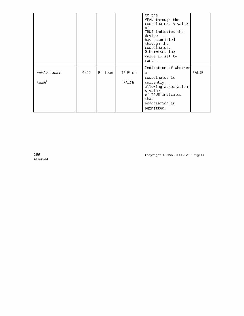
OPTICAL COMMUNICATION IEEE Std 802.15.7r1-20xx
Figure F.1—VLC application using traffic signal light sources
Figure F.2—VLC application using colored light sources
Copyright © 2011 IEEE. All rights reserved. 563
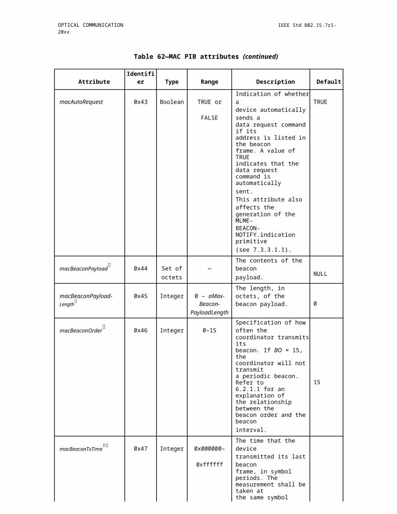
IEEE Std 802.15.7r1-20xx IEEE STANDARD FOR SHORT-RANGE WIRELESS
Figure F.3—VLC application using WDM technology
Of course, the VLC light source power can be also defined in radiometric unit, Watt. However, it is more reasonable that the light source power is defined in photometric unit because the light sources will be used not only for a VLC transmitter but also for illumination or visual display related to human eye.
Table F.1 describes the receiver input powers, calculated in Watts, from the assumption of 1 lumen on each of the seven color bands (given in Table 87). The assumption that the lights have only monochromatic component (shown as example wavelength in Table F.1) on each color band is also used for simple calculations. V() is the human eye sensitivity function, which indicates CIE sensitivity curves (Schubert [B12]).
Table F.1—Calculated color channel power at receiver
Wavelength band Spectral width Example V() at Receiver inputexample(nm) (nm) wavelength (nm) power (Watts) @ 1mwavelength
380 478 98 430 0.0273 0.0536
478 540 62 510 0.5030 0.0029
540 588 48 565 0.9788 0.0015
588 633 45 610 0.5030 0.0029
633 679 46 655 0.0817 0.0179
679 726 47 700 0.0041 0.3571
726 780 54 750 0.0001 14.6413
564 Copyright © 20xx IEEE. All rights reserved.

OPTICAL COMMUNICATION IEEE Std 802.15.7r1-20xx
The second factor causing the performance variation of a VLC receiver across multiple color channels is the photo sensitivity characteristics of optical receivers, such as Si photo-detectors, which is wavelength dependent. Figure F.4 shows the photo sensitivity characteristics of a Si photo-detector according to the wavelength variation. It has been known that the photo sensitivity value of Si photo-detector is higher on longer wavelength than on shorter wavelength in the visible band as shown in Figure F.4. Figure F.4 shows that a Si photo-detector produce more electrical current on red color channel than on green or blue color channel even though the radiometric received powers on each color channel are equal.
Table F.2 shows the photo-detector output current obtained from both the wavelength dependence of photo sensitivity shown in Figure F.4 and the conversion relations between the radiometric and photometric units described in Table F.1. The photo-detector output currents in Table F.2 were calculated only at 430 nm, 510 nm, and 655 nm among the example wavelengths in seven color bands, as shown in Table F.1, for convenience.
Table F.2 indicates that a VLC receiver with Si photo- detector performs differently on multiple color channels even though the radiometric received powers are equal on each color channel. Therefore, two main factors, the unit conversion and the photo sensitivity of a photo-detector depending on wavelength, need to be sufficiently considered in order that the performance of a VLC receiver can be maintained uniformly on multiple color channels.
phot
o se
nsiti
vity
(A/W
)
0.8
0.7
0.6
0.5 (0.46) Red
0.4
0.3 (0.3) Green
0.2(0.21)
Blue0.1
0.0 430 510 655
300 400 500 600 700 800 900 1000
wavelength (nm)
Figure F.4—Typical Si photo-detector wavelength sensitivity
Table F.2—Photo-detector current from Figure F.4 with conditions of Table F.1
Example wavelength Receiver input powerPhoto sensitivity (A/W)
Photo-detector output
(nm) (Watt) @ 1 m current (mA) @ 1 lm
430 0.0536 0.21 11.26
510 0.0029 0.30 0.87
655 0.0179 0.46 8.23
Copyright © 2011 IEEE. All rights reserved. 565

IEEE Std 802.15.7r1-20xx IEEE STANDARD FOR SHORT-RANGE WIRELESS
566 Copyright © 20xx IEEE. All rights reserved.