week 2.1 boolean algebra - pami.uwaterloo.capami.uwaterloo.ca/~basir/ece124/week2-1.pdf ·...
TRANSCRIPT
WEEK 2.1 BOOLEAN ALGEBRA
1

Boolean Algebra
Boolean algebra was introduced in 1854 by George Boole and in 1938 was shown by C. E. Shannon to be useful for manipulating Boolean logic functions.
The postulates and theorems of Boolean algebra are useful to simplify expressions, to prove equivalence of expressions, etc.
ECE 124 Digital Circuits and Systems Page 2

Axioms/Postulates of Boolean Algebra (1) Boolean algebra is an algebraic structure defined by a set of elements, B, together with two binary
operators + and * that satisfy the following postulates:
1. Postulate 1:
a) Closure with respect to +.
b) Closure with respect to *. 2. Postulate 2:
a) An identity element with respect to +, designated by 0.
b) An identity element with respect to *, designated by 1. 3. Postulate 3:
a) Commutative with respect to +.
b) Commutative with respect to *. 4. Postulate 4:
a) Distributive * over +.
b) Distributive + over *. 5. Postulate 5:
For each element x in B, there is an element : x in B (the complement) such that (a) x+ !x = 1 and (b) x * !x = 0.
6. Postulate 6:
There exists at least two elements x,y in B, such that x y.
ECE 124 Digital Circuits and Systems Page 3
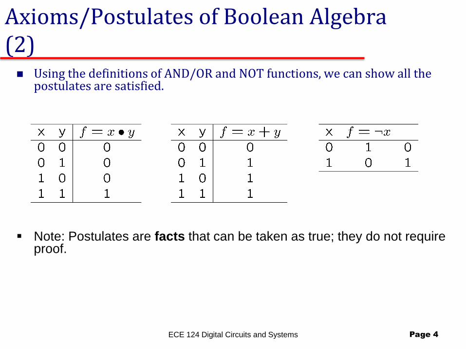
Axioms/Postulates of Boolean Algebra (2) Using the definitions of AND/OR and NOT functions, we can show all the
postulates are satisfied.
ECE 124 Digital Circuits and Systems Page 4
Note: Postulates are facts that can be taken as true; they do not require proof.

Theorems and Properties of Boolean Algebra Theorems help us out in manipulating Boolean expressions.
They must be proven from the postulates and/or other theorems known to be proven correct.
ECE 124 Digital Circuits and Systems Page 5
Note the duality in relationships if we interchange + with * and 0 with 1.

DeMorgan:
6
31
2
U?A
32
12
U?A
05
12
U?A
05
31
2
U?A
32
12
U?A
05
12
U?A
05
1
23
U?A
00𝑥 + 𝑦 = 𝑥′. 𝑦′ ′
(𝑥 . 𝑦 ) = 𝑥′ + 𝑦′ ′
(𝑥′. 𝑦′) = 𝑥 + 𝑦′
(𝑥′ + 𝑦 ) = 𝑥 . 𝑦′ ′
Synthesis
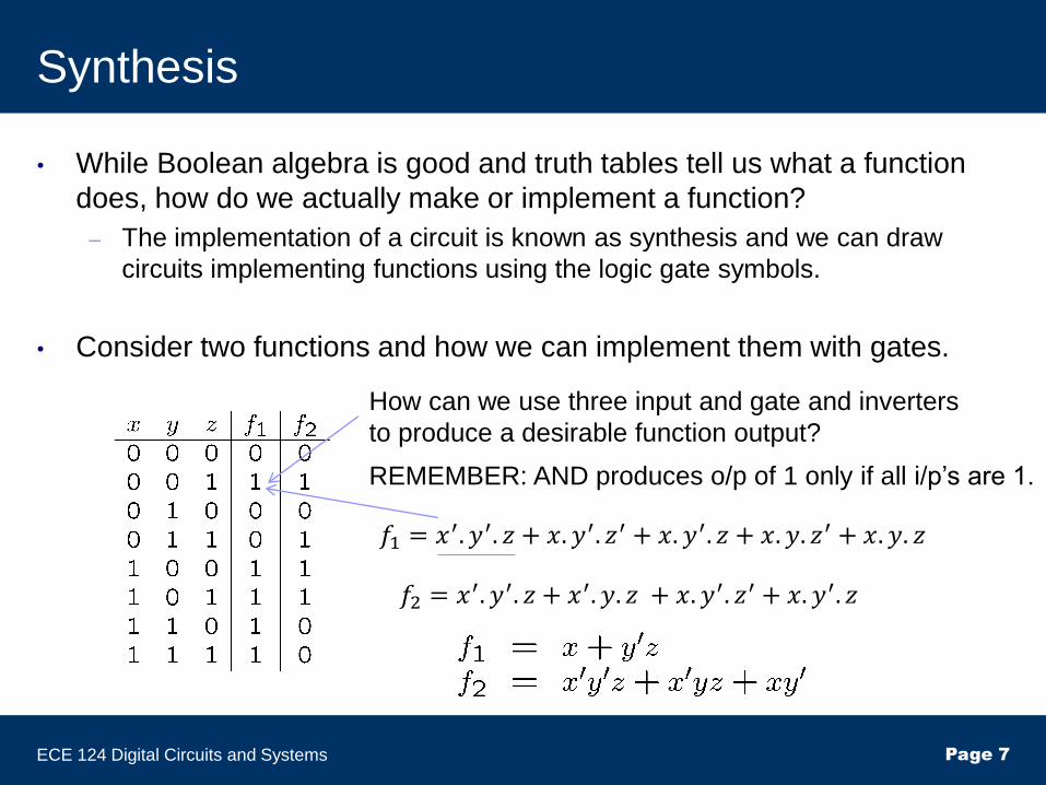
• While Boolean algebra is good and truth tables tell us what a function
does, how do we actually make or implement a function?
– The implementation of a circuit is known as synthesis and we can draw
circuits implementing functions using the logic gate symbols.
• Consider two functions and how we can implement them with gates.
ECE 124 Digital Circuits and Systems Page 7
𝑓1 = 𝑥′. 𝑦′. 𝑧 + 𝑥. 𝑦′. 𝑧′ + 𝑥. 𝑦′. 𝑧 + 𝑥. 𝑦. 𝑧′ + 𝑥. 𝑦. 𝑧
How can we use three input and gate and inverters
to produce a desirable function output?
REMEMBER: AND produces o/p of 1 only if all i/p’s are 1.
𝑓2 = 𝑥′. 𝑦′. 𝑧 + 𝑥′. 𝑦. 𝑧 + 𝑥. 𝑦′. 𝑧′ + 𝑥. 𝑦′. 𝑧

Synthesis Example for f1 and f2
ECE 124 Digital Circuits and Systems Page 8
• Circuit for f1:
• Circuit for f2:

Circuit cost for f1 and f2
ECE 124 Digital Circuits and Systems Page 9
• For a circuit, we will define a COST. We will ignore NOT gates at the inputs of a circuit;
all other gates count as 1 and every gate input will count as 1.
• Cost of f1 is 1 AND + 1 OR + 4 GATE INPUTS = 6.
• Cost of f2 is 3 AND + 1 OR + 11 GATE INPUTS = 15.
Synthesis Example for f2 (Again)
ECE 124 Digital Circuits and Systems Page 10
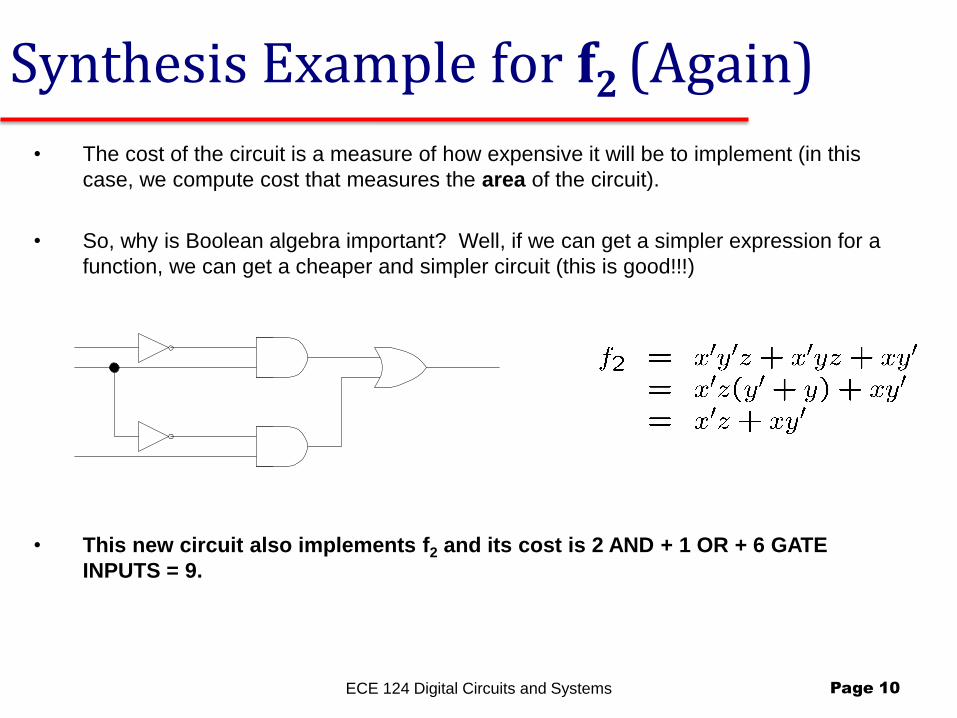
• This new circuit also implements f2 and its cost is 2 AND + 1 OR + 6 GATE
INPUTS = 9.
• The cost of the circuit is a measure of how expensive it will be to implement (in this
case, we compute cost that measures the area of the circuit).
• So, why is Boolean algebra important? Well, if we can get a simpler expression for a
function, we can get a cheaper and simpler circuit (this is good!!!)

Terminology
• Basic terminology…
• We have seen that Boolean algebra, logic, etc. works with binary variables.
• The variables have values in {0,1}; E.g., x in {0,1} and x is a binary variable.
• It is sometimes convenient to refer to the un-complemented (i.e., x) and complemented (i.e., !x) versions of a variable x.
• These two terms are called literals. – The un-complemented version x is called the positive literal of variable x. – The complemented version !x is called the negative literal of variable x.
• So, for each binary variable, there are two associated literals.
ECE 124 Digital Circuits and Systems Page 11

Minterms and Maxterms
• A truth table for an n-input function will have 2n rows.
• Minterms: – For each row of the truth table, create an AND of the literals according to the following
rule: If a variable has value 1 in the row, include its +ve literal. If a variable x has value 0 in the row, include its –ve literal.
– The resulting AND of each literal is called a MINTERM.
• Maxterms – For each row of the truth table, create an OR of the literals according to the fllowing rule:
If a variable x has value 0 in the row, include its +ve literal. If a variable x has value 1 in the row, include its –ve literal.
– The resulting OR of each literal is called a MAXTERM.
• So minterms and maxterms are created “opposite” of each other.
ECE 124 Digital Circuits and Systems Page 12

Illustration of Minterms and Maxterms.
ECE 124 Digital Circuits and Systems Page 13
• Minterms are denoted by a lower case “m” while Maxterms are denoted by an upper
case “M”.
• When a particular input pattern appears, its associated minterm will be 1 while all
other minterms will evaluate to 0.
• When a particular input pattern appears, its associated maxterm will be 0 while all
other maxterms will evaluate to 1.
• Minterms and maxterms are “duals” of each other; !mi = Mi and !Mi = mi

Canonical Sum-of-Products (SOP)
ECE 124 Digital Circuits and Systems Page 14
• Given a truth table, we can ALWAYS write a logic expression for the
function by taking the OR of the minterms for which the function is a 1.
– This representation of a function is a “sum of minterms” and is called a
canonical sum-of-products (SOP) representation of the function.
• Examples:
• Shortcut notation:

Sum-of-Products Implementations
• If implemented with gates, a SOP will always have the following form. – A plane of NOT gates (inverters to generate all literals), followed by…
– A plane of AND gates (to implement the minterms), followed by…
– A single OR gate (to take the “sum”).
ECE 124 Digital Circuits and Systems Page 15

Canonical Product-of-Sums (POS)
ECE 124 Digital Circuits and Systems Page 16
• Given a truth table, we can ALWAYS write a logic expression for the function
by taking the AND of the maxterms for which the function is a 0.
– This representation of a function is a “product of maxterms” and is called a canonical
product-of-sums (POS) representation of the function.
• Examples:
• Shortcut notation:

Product-Of-Sums Gate Implementations
• If implemented with gates, a POS will always have the form: – A plane of NOT gates (inverters to generate all literals), followed by…
– A plane of OR gates (to implement the maxterms), followed by…
– A single AND gate (to take the “product”).
ECE 124 Digital Circuits and Systems Page 17

General Comments
• There are always two canonical representations for a function, the SOP or the POS.
• Sometimes, one implementation is simpler than the other implementation (in terms of its cost).
• SOP and POS implementations are often referred to as 2-level logic implementations.
– This is because we assume NOT gates at the input are free, so we see that there are two levels of gates (AND-OR for SOP and OR-AND for POS) required to implement the function.
ECE 124 Digital Circuits and Systems Page 18

Conversion between SOP and POS
• It is always possible to convert between a POS and SOP representation for a functin.
• Consider f1= (1,4,7) which can also be expressed as f1 = (0,2,3,5,6).
f1 = (1,4,7)
= m1+m4+m7
= !(!f1) // double inversion is okay
= !(m0 + m2 + m3 + m5 + m6) // !f1 is those minterms not in f1
= (!m0)(!m2)(!m3)(!m5)(!m6)
= (M0)(M2)(M3)(M5)(M6)
= (0,2,3,5,6).
• Note: Quickly, we can from minterms (maxterms) to maxterms (minterms) by changing () to () and list those indices of terms missing from the original list.
ECE 124 Digital Circuits and Systems Page 19
Standard Sum-Of-Products (1)
• A function described using a canonical SOP (minterms) is by no means minimal. It might require more gates/literals than required.
• Let us call any AND of literals a product term.
• We can then express logic functions in Standard Sum-Of-Products form where, instead of minterms, the AND terms are simply product terms.
• We can start with a canonical SOP and use Boolean algebra to simply the expression into something simpler.
ECE 124 Digital Circuits and Systems Page 20

Standard Sum-Of-Products (2)
ECE 124 Digital Circuits and Systems Page 21
• Let’s consider one of our previous functions in Canonical SOP.
• If we used Boolean algebra to simplify, we would find that f2 can also
be written as a Standard SOP using a sum of product terms:

Standard Product-Of-Sums (1)
• A function described using a canonical POS (maxterms) is by no means minimal. It might require more gates/literals than required.
• Let us call any OR of literals a sum term.
• We can then express logic functions in Standard Product-Of-Sums form where, instead of maxterms, the OR terms are simply sum terms.
• We can start with a canonical POS and use Boolean algebra to simply the expression into something simpler.
ECE 124 Digital Circuits and Systems Page 22

Example of Standard Product-Of-Sums Forms
• Let’s consider one of our previous functions in Canonical POS.
ECE 124 Digital Circuits and Systems Page 23
• If we used Boolean algebra to simplify, we would find that f1 can also
be written as a Standard POS using a product-of-sum terms:

Other Logic Gates
• Although we can always implement any function we want using AND/OR/NOT, there are other types of logic gates that prove useful.
ECE 124 Digital Circuits and Systems Page 24

NAND and NOR gates (2-inputs)
NAND gate performs a “NOT-AND” operation.
ECE 124 Digital Circuits and Systems Page 25
• NAND/NOR gates can be extended to multiple inputs, but the NAND/NOR gates are
not associative (explained later). We should always think of NAND as “NOT-AND”
and NOR as “NOT-OR”.
• NOR gate performs a “NOT-OR” operation.

NAND and NOR gates (n-inputs)
• Think of multiple input NAND/NOR gates in terms of the operations they perform; i.e., NOT-AND (for a NAND) and NOT-OR (for a NOR).
• Example: 3-input versions:
ECE 124 Digital Circuits and Systems Page 26

XOR and NXOR gates (2-inputs)
• XOR gate (with 2-inputs performs a “difference operation”):
ECE 124 Digital Circuits and Systems Page 27
• XOR/NXOR gates are incredibly useful for arithmetic operations like
addition/subtraction/multiplication. These gates can also be extended to multiple
inputs, but we need to be clear on their definitions with multiple inputs.
• NXOR gate (with 2-inputs performs a “equivalence operation”):

XOR gates with multiple inputs.
• A XOR gate with > 2 inputs performs the “odd operation”; the output is a 1 whenever an odd number of inputs are 1.
• Example: 3-input versions:
ECE 124 Digital Circuits and Systems Page 28
• XOR gates are associative (explained later).
NXOR gates with multiple inputs.
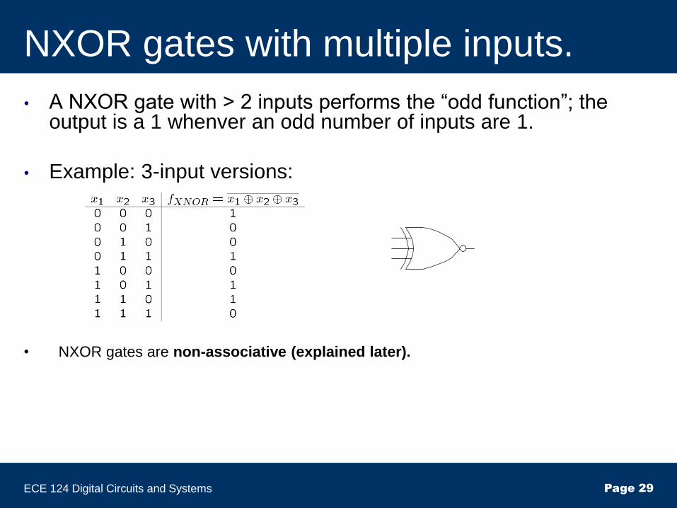
• A NXOR gate with > 2 inputs performs the “odd function”; the output is a 1 whenver an odd number of inputs are 1.
• Example: 3-input versions:
ECE 124 Digital Circuits and Systems Page 29
• NXOR gates are non-associative (explained later).

Buffer (1-input)
• Does nothing logically; Used in implementation to “boost” a signal’s strength.
ECE 124 Digital Circuits and Systems Page 30

Associative and Non-Associative Gates
AND/OR gates are associative gates. This means that we can collapse
many smaller AND (OR) gates into a single AND (OR) gate with
multiple inputs.
Example:
ECE 124 Digital Circuits and Systems Page 31
• XOR gates are also associative. Not all types of logic gates are associative.

Non-Associative Gates
NAND/NOR and NXOR gates are not
associative.
ECE 124 Digital Circuits and Systems Page 32

Example 1: Proof of a Theorem
• Prove Absorption Theorem 6(a)
• Can prove using postulates, or using truth tables.
• Solution:
ECE 124 Digital Circuits and Systems Page 33

Example 2: Expression Simplification
• Simply the following logic expression:
• Solution …
• Note: Could have also asked “Show that” (i.e., LHS = RHS):
ECE 124 Digital Circuits and Systems Page 34