welcome to select 595183 manual hydraulic stacker
TRANSCRIPT
Welcome to select 595183 manual hydraulic stacker.
Warning!
Pay attention to the following matters before operating this stacker:
1. 595183 manual hydraulic stacker can only be operated indoor on level and solid ground and it is strictly prohibited to operate this stacker in a corrosive environment with acid and alkali.
2.Please read this manual carefully and understand the performance of this stacker before operating; Inspection of the stacker should be conducted carefully every time before operation to ensure that the stacker is in normal condition. It is strictly prohibited to operate a stacker with trouble.
3.It is strictly prohibited to operate the stacker when overloaded. The load capacity and the load center should meet the requirements in the parameter table of this manual.
4.When 595183 stacker is used for piling, the gravity center of the goods must be within the two forks and it is strictly prohibited to pile bulk goods. 5.When it is required to transport the goods for a comparatively long distance, the height of the forks from the ground should not exceed 0.5m. 6.When piling goods, it is strictly prohibited for people to stand under the forks or around the stacker. 7.It is strictly prohibited to stand on the forks for operation. 8.When the goods are on high level, the goods should be pushed forward or pulled backward slowly and no cornering is allowed in such a case.
I. Applications
595183 manual hydraulic stacker is a vehicle used for high lift loading and unloading and short distance transportation. As no sparks and electromagnetic field are generated, the stacker is especially suitable for truck loading and unloading as well as the loading and unloading and transportation of flammable and fire prohibited goods in workshops, warehouses, dock, station and freight yard, etc. The stacker is characterized in smooth lifting, flexible cornering and convenient operation, etc. To ensure safe and reliable operation, the universal wheels are equipped with braking device, which are ideal tool for reducing labor intensity, improving production efficiency and achieving safe loading and unloading.
--1--

II.Key technical parameters:
--2--
Model 595183 Rated loading capacity Q (kg) 1000 1000 Max. lifting height H (mm) 500 500 Minimum height of the forks h (mm) 336 370 Length of forks L (mm) 2050 1840 Load center C(mm) 1600 2500 Width of fork E (mm) 2155 3055 Length of the stacker A (mm) 70 70 Width of the stacker B (mm) 1300/1560 1300/1560
Height of the stacker F (mm) 1450 1450 Minimum clearance from ground X (mm) 30/100/800
(1060) 30/100/800(1060)
Stage number of door frame 950 950 Lifting speed,full / no load mm/rime 25 25 Decline speed, full / no load mm/s 1500/2100 1500/2100 Cornering radius R(mm) 1542/2158 1542/2158 Front wheel size (mm) 1235 1235 Back wheel size (mm) 25 25 Dead weight (kg) Controllable Controllable

III Structural characteristics 595183 manual hydraulic stacker consists of a hydraulic system and a door frame.
The stacker uses a manual hydraulic jack (hydraulic device) as force to lift heavy goods, which are pushed, pulled and handled manually. The hydraulic device is equipped with an oil return valve and the fork decline speed is controlled via a hand lever to make the operation of the hydraulic system correct, safe and reliable. The door frame is welded with high quality section steel such as to good rigidity and high strength. Universal wheels with braking device are adopted as the back wheels, which can rotate freely, easily and flexibly. Both front and back wheels are installed on wheel shafts with ball bearings so as to rotate flexibly. Wear-resistant and durable Nylon wheels are adopted so that it is not easy to damage the operation ground. When lifting goods, insert the forks under the pallet of the goods, when necessary, brake the back wheels and pull the hand lever. The pinch wheel presses the pump core to make the oil in the pump cylinder flow into the piston cylinder, in order to push the piston rod move upward and lift the forks upward via a chain for a two times travel. Pull the hand lever back and forth so as to lift the goods and achieve the purpose of lifting. When the forks are lifted to the maximum height, the pressurized oil flows back into the oil tank via an oil draining hole and in that case, even the hand lever is pulled, the forks rise no more to avoid damaging components by impacting the top. When handling heavy goods, the stacker is able to travel via manual pushing (pulling). When unloading, pull the unloading hand lever, the oil return valve opens and with the effect of the dead weight of the heavy goods and forks, the operational oil in the piston cylinder flows back into the oil tank through the oil return valve, and when the piston rod and the forks decline to the lowest position, the goods are unloaded and the forks are withdrawn.
Operation conditions The operation of 595183 manual hydraulic stacker should meet following conditions:
1.Ambient temperature for operation:-25℃~+40℃. 2.The relative humidity of the environment should be less than 90%RH. 3.The stacker can only operate in an environment without rain and harmful gas erosion. 4.The stacker can only operate indoor on level and solid ground.
V. Operation and maintenance 1. The oil must be filtered and clean and ensure sufficient oil quantity. 2. Before operation, inspection must be conducted for the stacker to ensure the stacker is in normal condition and there is no loose component. 3.The goods should be smoothly distributed on the forks and no overload is allowed.
--3-- 4.After the operation is completed, the heavy goods should be unloaded and the heavy good are not allowed to be on the forks for a long time. 5.When lowering goods, the hand lever of the oil return valve should be operated slowly and gently to avoid sudden declination during quick declination
process which causes unsafe situation. When lowering the goods quickly, the oil return valve must not be closed suddenly as inertial acceleration is generated during the process of quick declination. If that, a great force will be generated to damage the components and goods.
6.Raise and pull outward the front part of the panel by hands, take off the panel and then the stacker can be used as pallet transporting cart or pallet stacker. 7.The brakes on back wheels are installed for the purpose of safety in operation process. When the forks are rising for lifting goods or is used as an
operation platform, the brakes should be stepped down with foot to prevent the stacker from moving.
VI. Possible failures in operation and trouble shooting Number Failure Cause analysis Trouble shooting
1 The lifting height cannot meet the design requirement
Insufficient operation oil To fill oil into the oil cylinder, turn out the bolt, fill in filtered and clean operation oil to the oil inlet height and then tighten the bolt.
2 When the hand lever is pulled, the forks do not rise.
1. The viscosity of the operation oil is too great or no operation oil has been filled in
Replace or fill in operation oil according to the oil quantity regulated.
2.There is foreign matter in operation oil, which makes the oil inlet valve cannot be tightly closed.
Filter out the foreign matter or replace operation oil according to the stipulation.
3. The oil draining valve, unloading hand lever and tension spring do not work, are not at the lowest position or stuck by other foreign mater.
Examine the tension spring to see if it is correct, adjust the unloading hand lever to the lowest close position and remove foreign mater.
4. The positions of the oil draining valve and unloading hand lever have not been correctly adjusted.
Readjust the unloading tension bar nut position.
3 After being raised, the forks do not decline
1. The unloading hand lever is not correctly adjusted. 2.Too great piston load deviation so permanent deformation occurs. 3. The fork frame, roller or chain wheel is stuck
Adjust as described above, disassemble for maintenance or replace the piston rod, disassemble for maintenance or replace bearing
4 Oil leakage 1. Damaged or failed seal washer 2. There is slight crack or through hole in individual component 3. Loose thread connection or non-tightly pressed sealing ring
Replace with new sealing washer, repair or replace new components, repair and tighten
--4--
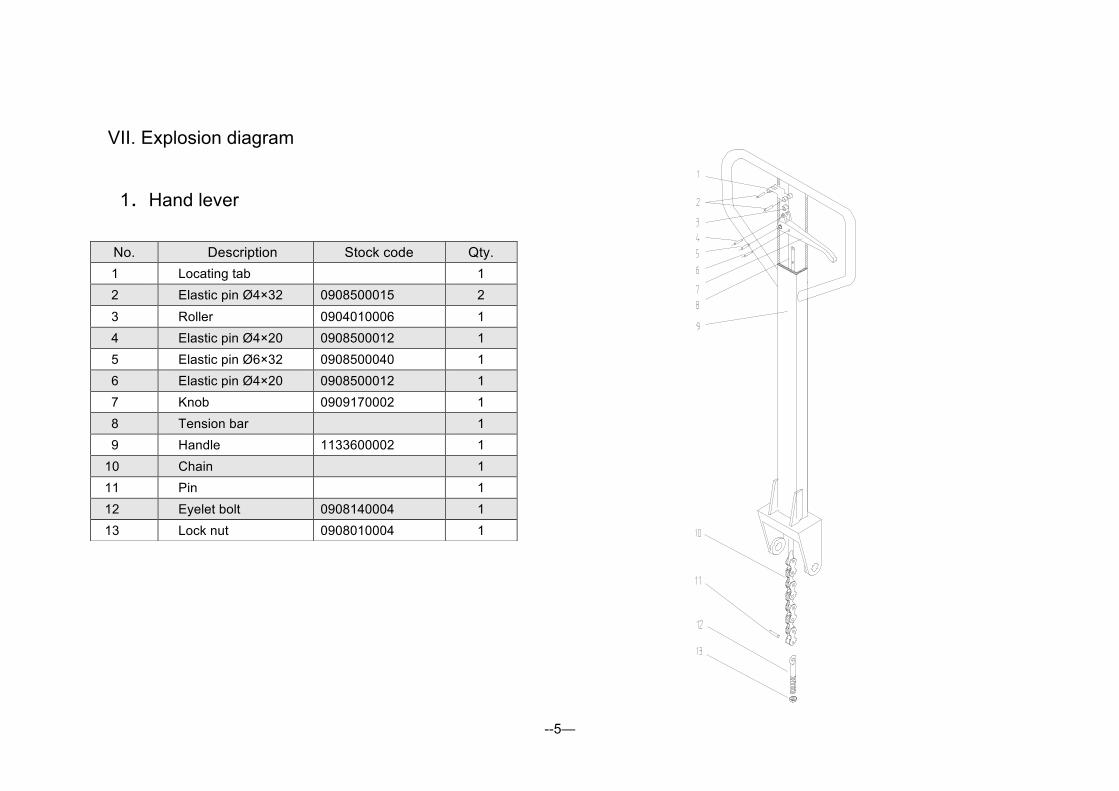
VII. Explosion diagram
1.Hand lever
--5—
No. Description Stock code Qty. 1 Locating tab 1
2 Elastic pin Ø4×32 0908500015 2 3 Roller 0904010006 1 4 Elastic pin Ø4×20 0908500012 1 5 Elastic pin Ø6×32 0908500040 1 6 Elastic pin Ø4×20 0908500012 1 7 Knob 0909170002 1 8 Tension bar 1 9 Handle 1133600002 1 10 Chain 1 11 Pin 1 12 Eyelet bolt 0908140004 1 13 Lock nut 0908010004 1

2.Jack:
--6--
No. Description Stock code Qty 1 Hex nut M6 0908030012 2 2 Screw M6×25 0908170014 1 3 Lever plate 0860010007 1 4 Striker 090109007 1 5 O ring Ø4.87×1.8 0902050003 2 6 Striker spring 0903040003 1 7 Striker valve seat 0901100003 1 8 Combined washer Ø20 0902010009 2 9 O ringØ12.5×2.65 0902050028 2
10 Steel ball Ø8 0907010014 1 11 Bolt M8×50 0908420039 1 12 NutM8 0908030013 1 13 Pin Ø3×15.7 0908470003 1 14 Valve seat 1000 0901110007 1 15 Steel ball Ø5 0907010010 1 16 Pin 0901150010 1 17 Valve seat spring 0903080002 1 18 Combined washer Ø10 0902010004 1 19 Bolt 0901120036 1 20 Combined bushing 1220 0907040011 1 21 Combined bushing 2017 0907040023 2 22 Compressed frame 0860010014 1 23 Elastic pin Ø4×25 0908500014 1
--7--
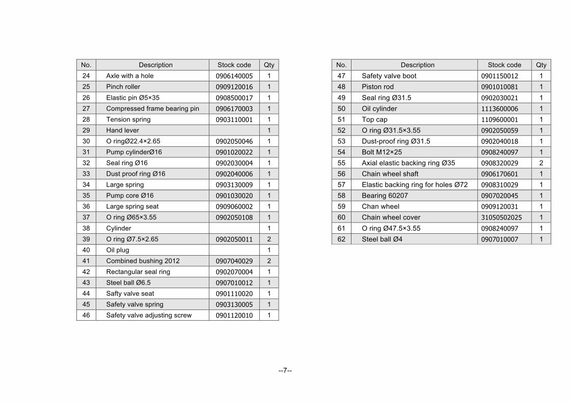
No. Description Stock code Qty 24 Axle with a hole 0906140005 1 25 Pinch roller 0909120016 1 26 Elastic pin Ø5×35 0908500017 1 27 Compressed frame bearing pin 0906170003 1 28 Tension spring 0903110001 1 29 Hand lever 1 30 O ringØ22.4×2.65 0902050046 1 31 Pump cylinderØ16 0901020022 1 32 Seal ring Ø16 0902030004 1 33 Dust proof ring Ø16 0902040006 1 34 Large spring 0903130009 1 35 Pump core Ø16 0901030020 1 36 Large spring seat 0909060002 1 37 O ring Ø65×3.55 0902050108 1 38 Cylinder 1 39 O ring Ø7.5×2.65 0902050011 2 40 Oil plug 1 41 Combined bushing 2012 0907040029 2 42 Rectangular seal ring 0902070004 1 43 Steel ball Ø6.5 0907010012 1 44 Safty valve seat 0901110020 1 45 Safety valve spring 0903130005 1 46 Safety valve adjusting screw 0901120010 1
No. Description Stock code Qty 47 Safety valve boot 0901150012 1 48 Piston rod 0901010081 1 49 Seal ring Ø31.5 0902030021 1 50 Oil cylinder 1113600006 1 51 Top cap 1109600001 1 52 O ring Ø31.5×3.55 0902050059 1 53 Dust-proof ring Ø31.5 0902040018 1 54 Bolt M12×25 0908240097 1 55 Axial elastic backing ring Ø35 0908320029 2 56 Chain wheel shaft 0906170601 1 57 Elastic backing ring for holes Ø72 0908310029 1 58 Bearing 60207 0907020045 1 59 Chan wheel 0909120031 1 60 Chain wheel cover 31050502025 1 61 O ring Ø47.5×3.55 0908240097 1 62 Steel ball Ø4 0907010007 1

3. Fork frame assembly :
-8--
No. Description Stock code Qty 1 Locking screw M16×50 0908220014 4
2 Steel ball Ø19 0907010026 4 3 Bearing 60207 0907020045 4 4 Axial elastic backing ring Ø35 0908320029 4 5 Large pulley 0909120008 4 6 Fork frame 1 7 Forks 2
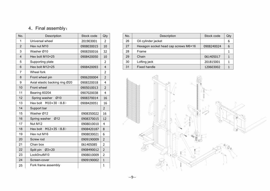
4.Final assembly:
No. Description Stock code Qty 26 Oil cylinder jacket 6
27 Hexagon socket head cap screws M6×16 0908240024 6
28 Frame 1
29 Chain 061405017 1
30 Lofting jack 201815001 1
31 Fixed handle 120603002 1
No. Description Stock code Qty 1 Universal wheel 201903001 2
2 Hex nut M10 0908030015 10
3 Washer Ø10 0908350016 32
4 Hex bolt M10×25 0908420050 10
5 Supporting plate 2
6 Hex bolt M12×25 0908420093 4
7 Wheel fork 2
8 Front wheel pin 0906200004 2
9 Axial elastic backing ring Ø20 0908320018 4
10 Front wheel 0905010013 2
11 Bearing 60204 0907020038 4
12 Spring washer Ø10 0908370014 16
13 Hex bolt M10×30(8.8) 0908420051 16
14 Support bar 2
15 Washer Ø12 0908350022 16
16 Spring washer Ø12 0908370015 12
17 Nut M12 0908010010 4
18 Hex bolt M12×35(8.8) 0908420187 8
19 Hex nut M16 0908030021 6
20 Screw rod 0909190009 2
21 Chan box 061405085 2
22 Split pin Ø3×20 0908490012 2
23 Lock0nutM10 0908010009 2
24 Screen-cover 0909190002 1
25 Fork frame assembly 1
--9--

Packing list
595183 Manual Hydraulic Stacker
Consignee: Ex-factory number:
Contract number: Ex-factory date:
序号 Name Quantity Net weight
(kg) Overall dimension(L×W×H) Remark
1 595183 manual hydraulic stacker 1 255 1600×1470×2090 The whole unit
2 595183 operation manual 1 3 Quality certificate 1 4 Packing list 1 6 Combined washer Φ20 2
Jack
7 O seal ring Φ47.5×3.55 1 8 O seal ringΦ65×3.55 1 9 UHS seal ringΦ16 1 10 UHS seal ringΦ31.5 1 11 DHS dust-proof ring Φ16 1 12 DHS dust-proof ring Φ31.5 1
--10--