welding of tool steel - uddeholm - uddeholms ab - swedish quality
TRANSCRIPT

WELDING OF TOOL STEEL

SS-EN ISO 9001SS-EN ISO 14001
This information is based on our present state of knowledge and is intended to provide generalnotes on our products and their uses. It should not therefore be construed as a warranty ofspecific properties of the products described or a warranty for fitness for a particular purpose.
Classified according to EU Directive 1999/45/ECFor further information see our “Material Safety Data Sheets”.
Edition 6, – Revised 02.2014, not printed
The latest revised edition of this brochure is the English version,which is always published on our web site www.uddeholm.com
WELDING OF TOOL STEEL
3
CONTENTS
General information on welding of tool steel ................... 4
Welding methods for tool steel ............................................ 4
The welding bay ........................................................................ 6
Filler material ............................................................................. 7
Hydrogen in tool steel ............................................................ 8
Elevated working temperature .............................................. 9
Welding procedure .................................................................. 10
Het treatment after welding .................................................. 11
Guidelines for welding in
– hot work tool steel ............................................................ 13
– cold work tool steel .......................................................... 14
– plastic mould steel .............................................................. 17

4
WELDING OF TOOL STEEL
General informa-tion on welding oftool steelTool steel contain up to 2.5% carbonas well as alloying elements such asmanganese, chromium, molybdenum,tungsten, vanadium and nickel. Themain problem in welding tool steelstems from its high hardenability.Welds cool quickly once the heatsource is removed and the weldmetal and part of the heat-affectedzone will harden. This transformationgenerates stresses because the weldis normally highly constrained, with aconcomitant risk for cracking unlessgreat care is exercised.
In what follows, a description isgiven of the welding equipment,
Welding methodsfor tool steelShielded metal-arc welding(SMAW or MMA)
PRINCIPLE
An electric arc generated by a DC orAC power source is struck betweena coated, rod-like electrode and thework-piece (Fig. 1).
The electrodes consist of a centralwire core, which is usually low-carbon steel, covered with a coatingof pressed powder (flux). The consti-tution of this coating is complex andconsists of iron powder, powderedferro-alloys, slag formers and a suit-able binder. The electrode is con-sumed under the action of the arcduring welding and drops of moltenmetal are transferred to the work-piece. Contamination by air duringthe transfer of molten drops fromelectrode to workpiece and duringsolidification and cooling of the welddeposit is inhibited partly by slagformed from constituents in the elec-trode coating and partly by gasescreated during melting of the elec-trode.
The composition of the depositedweld metal is controlled via the con-stitution of the electrode coating.
POWER SOURCE
For MMA welding, it is possible touse either an AC or DC powersource. However, whichever is used,the source must provide a voltageand current which is compatible withthe electrode. Normal arc voltagesare:• normal recovery electrodes:
20–30 V• high recovery electrodes:
30–50 V
Uddeholm welding consumables areof normal recovery type. A suitablepower source for these is a DC unitwith an open voltage of 70 V andwhich is capable of delivering 250A/30V at 35% intermittence.
welding technique and weld con-sumables that are required in orderto weld tool steel successfully. Ofcourse, the skill and experience ofthe welder is also a vital ingredient inobtaining satisfactory results. Withsufficient care, it is possible toachieve weld repairs or adjustmentswhich, in terms of tooling perform-ance, are hardly inferior to that of thebase steel.
Welding of tooling may be requiredfor anyone of the following reasons:
• refurbishment and repair ofcracked or worn tooling
• renovation of chipped or worncutting edges, e.g. on blanking tools
• adjustment of machining errors intool making
• design changes

WELDING OF TOOL STEEL
5
Laser Welding
PRINCIPLE
High power laser light is generatedand focused through a lens to thewelding spot. As filler material a thinwire with a diameter between 0.1–0.6 mm is primarily used. The welderguides the wire to the area to bewelded. The laser beam melt thewire and the base material. The mol-ten material solidifies leaving behinda small raised area. The welder con-tinues spot by spot and line by line.Argon gas shields the process fromoxidation (Fig.3).
Fig. 1 Shielded Metal-Arc Welding SMAW (MMA)
Fig. 2 Gas Tungsten Arc Welding GTAW (TIG)
Fig. 3 Laser Welding
Gas tungsten-ARC welding
(GTAW or TIG)
PRINCIPLE
In MMA welding, the electrode fromwhich the arc is struck is consumedduring welding.
The electrode in TIG welding ismade of tungsten or tungsten alloywhich has a very high melting point(about 3300°C/6000°F) and is there-fore not consumed during the proc-ess (Fig. 2). The arc is initially struckby subjecting the electrode-work-piece gas to a high-frequency voltage.The resulting ionization permits strik-ing without the necessity for contactbetween electrode and workpiece.The tungsten electrode is alwaysconnected to the negative terminal ofa DC power source because this
Slag
WeldMelt pool
Coating
Core wireElectrodeholder
+ Pole
– PolePower source
Protective gas
Filler material
Tungsten electrode
Cooling water
Electrode holder
– Pole
+ PolePower source
Protective gasProtective glass
Laser beam
Filler wire
Workpiece
Deposited material
Fusion zone
minimizes heat generation and there-by any risk of melting the electrode.Current is conducted to the elec-trode via a contact inside the TIG-gun. Any consumables which arerequired during TIG-welding are fedobliquely into the arc in the form ofrod or wire. Oxidation of the weldpool is prevented by an inert-gasshroud which streams from the TIGgun over the electrode and weld.
POWER SOURCE
TIG welding can be performed with aregular MMA power source providedthis is complemented with a TIGcontrol unit. The gun should be watercooled and be capable of handling aminimum current of 250 A at 100%intermittence. A gas lens is also adesirable feature in order that the
inert gas protection is as efficient aspossible. Welding is facilitated if thecurrent can be increased steplesslyfrom zero to the optimum level.

6
WELDING OF TOOL STEEL
Grinding machinesThe following should be available:
• disc grinder with minimum180 Ø x 6 mm wheel (7 Ø x 0,25”)for preparing the joint and grindingout of any defects which may occurduring welding
• flat grinder capable of ≥25 000 rpmfor grinding of minor defects and ofthe finished weld
• if a welded mould is subsequentlyto be polished or photo-etched, itmay be necessary to have a grindercapable of giving a sufficiently finefinish
• small rotating metal files in differentshapes and sizes
The welding bayIn order to be able to effect satisfac-tory welding work on tool steel, thefollowing items of equipment are tobe regarded as minimum require-ments.
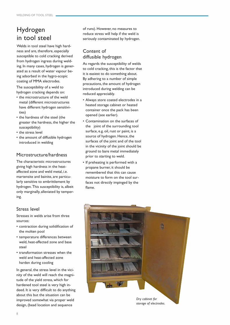
Dry cabinetThe coated electrodes used for MMAwelding are strongly hygroscopic andshould not be allowed to come intocontact with anything other than dryair. Otherwise, the weld will be con-taminated with hydrogen (see later).Hence, the welding bay should beequipped with a dry cabinet for stor-
Preheating in an insulated box.
Electrical elements for an insulatedpreheating box.
WorkbenchIt is particularly important duringcritical welding operations, of thetype performed with tool steel, thatthe welder enjoys a comfortableworking position. Hence, the work-bench should be stable, of the cor-rect height a sufficiently level that the
Preheating equipmentTool steel cannot be welded at roomtemperature without considerablerisk for cracking and it is generallynecessary to pre-heat the mould ordie before any welding can beattempted (see later). While it iscertainly possible to weld tools suc-cessfully by preheating in a furnace,the chances are that the temperaturewill fall excessively prior to comple-tion of the work. Hence, it is recom-mended that the tool be maintainedat the correct temperature using anelectrical heating box supplied from acurrent-regulated DC source. Thisequipment also enables the tool tobe heated at a uniform and control-led rate.To place the tool on a heated tableor plate could sometimes be suffi-cient to maintain the temperature.
For minor repairs and adjustments,it is acceptable that the tool is pre-heated using a propane torch. Hence,liquid propane cylinders should beavailable in the welding bay.
age of electrodes. This should bethermostatically controlled in therange 50–150°C (120–300°F). Theelectrodes should be removed fromtheir containers and lie loose onracks.
For welding of tooling outside thewelding bay, it will also be found use-ful to have a portable heated con-tainer in which the electrodes can becarried.
work can be positioned securely andaccurately. It is advantageous if theworkbench is rotatable and adjust-able vertically, since both these fea-tures facilitate the welding operation.
POWER SOURCE
For deposition welding normally apulsed solid state laser of Nd: YAGtype is used.
Typical performance:
Nominal output 150–200 W
Max pulse output 10–12 kW
Pulse time 0.5–20 ms
Frequence 0.5–20 Hz
Spot diameter 0.5–2.0 mm (0.1–0.5 mm)
WELDING OF TOOL STEEL
7
Filler materialThe chemical composition of a welddeposit is determined by the compo-sition of the consumable (filler metal),the base steel composition and theextent to which the base material ismelted during welding. The consum-able electrode or wire should mixeasily with the molten base steelgiving a deposit with:
• uniform composition, hardness andresponse to heat-treatment
• freedom from non-metallic inclu-sions, porosity or cracks
• suitable properties for the toolingapplication in question
Since tool steel welds have high hard-ness, they are particularly susceptibleto cracking which may originate atslag particles or pores. Hence, theconsumable used should be capableof producing a high-quality weld. In asimilar vein, it is necessary that theconsumables are produced with verytight analysis control in order thatthe hardness as welded and theresponse to heat treatment is repro-ducible from batch to batch. High-quality filler metals are also essentialif a mould is to be polished or photo-etched after welding. Uddeholmwelding consumables meet theserequirements.
Filler rods are normally producedfrom electro-slag remelted stock.The coated electrodes are of basictype, which are far superior to rutileelectrodes as regards weld cleanli-ness. Another advantage with basiccoated electrodes over those ofrutile type is that the former give amuch lower hydrogen content in theweld metal.
In general, the consumable usedfor welding tool steel should be simi-lar in composition to the base mate-rial. When welding in the annealedcondition, e.g. if a mould or die hasto be adjusted while in the processof manufacture, it is vital that thefiller metal has the same heat treat-ment characteristics as the basesteel, otherwise the welded area inthe finished tool will have differenthardness. Large compositional differ-ences are also associated with anincreased cracking risk in connectionwith hardening.
Uddeholm welding consumable aredesigned to be compatible with thecorresponding tool steel grades irre-spective of whether welding is car-ried out on annealed or hardened-and tempered base material.
Obviously, the weld metal ofwelded tools will require differentproperties for different applications.
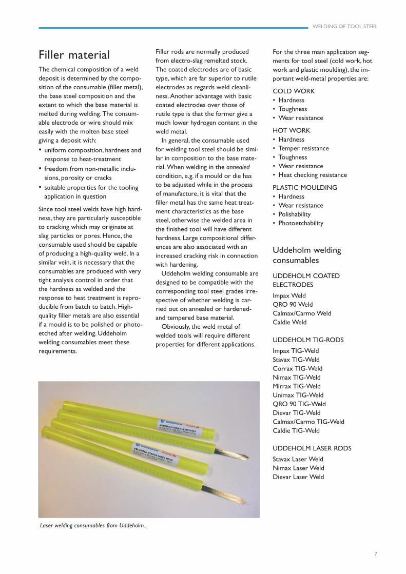
Laser welding consumables from Uddeholm.
For the three main application seg-ments for tool steel (cold work, hotwork and plastic moulding), the im-portant weld-metal properties are:
COLD WORK• Hardness• Toughness• Wear resistance
HOT WORK• Hardness• Temper resistance• Toughness• Wear resistance• Heat checking resistance
PLASTIC MOULDING• Hardness• Wear resistance• Polishability• Photoetchability
Uddeholm weldingconsumables
UDDEHOLM COATEDELECTRODES
Impax WeldQRO 90 WeldCalmax/Carmo WeldCaldie Weld
UDDEHOLM TIG-RODS
Impax TIG-WeldStavax TIG-WeldCorrax TIG-WeldNimax TIG-WeldMirrax TIG-WeldUnimax TIG-WeldQRO 90 TIG-WeldDievar TIG-WeldCalmax/Carmo TIG-WeldCaldie TIG-Weld
UDDEHOLM LASER RODS
Stavax Laser WeldNimax Laser WeldDievar Laser Weld
8
WELDING OF TOOL STEEL
The susceptibility of a weld tohydrogen cracking depends on:• the microstructure of the weld
metal (different microstructureshave different hydrogen sensitivi-ties)
• the hardness of the steel (thegreater the hardness, the higher thesusceptibility)
• the stress level• the amount of diffusible hydrogen
introduced in welding
Microstructure/hardnessThe characteristic microstructuresgiving high hardness in the heat-affected zone and weld metal, i.e.martensite and bainite, are particu-larly sensitive to embrittlement byhydrogen. This susceptibility is, albeitonly marginally, alleviated by temper-ing.
Stress levelStresses in welds arise from threesources:
• contraction during solidification ofthe molten pool
• temperature differences betweenweld, heat-affected zone and basesteel
• transformation stresses when theweld and heat-affected zoneharden during cooling
In general, the stress level in the vici-nity of the weld will reach the magni-tude of the yield stress, which forhardened tool steel is very high in-deed. It is very difficult to do anythingabout this but the situation can beimproved somewhat via proper welddesign, (bead location and sequence
Hydrogenin tool steelWelds in tool steel have high hard-ness and are, therefore, especiallysusceptible to cold cracking derivedfrom hydrogen ingress during weld-ing. In many cases, hydrogen is gener-ated as a result of water vapour be-ing adsorbed in the hygro-scopiccoating of MMA electrodes.
Dry cabinet forstorage of electrodes.
of runs). However, no measures toreduce stress will help if the weld isseriously contaminated by hydrogen.
Content ofdiffusible hydrogenAs regards the susceptibility of weldsto cold cracking, this is the factor thatit is easiest to do something about.By adhering to a number of simpleprecautions, the amount of hydrogenintroduced during welding can bereduced appreciably.
• Always store coated electrodes in aheated storage cabinet or heatedcontainer once the pack has beenopened (see earlier).
• Contamination on the surfaces ofthe joint of the surrounding toolsurface, e.g. oil, rust or paint, is asource of hydrogen. Hence, thesurfaces of the joint and of the toolin the vicinity of the joint should beground to bare metal immediatelyprior to starting to weld.
• If preheating is performed with apropane burner, it should beremembered that this can causemoisture to form on the tool sur-faces not directly impinged by theflame.

WELDING OF TOOL STEEL
9
Uddeholm Stavax Weld/TIG-Weld andUddeholm Impax Weld/TIG-Weld matchtheir corresponding tool steel gradesexactly and give perfect results afterpolishing or texturing of a welded mould.
Elevated workingtemperatureThe basic reason for welding toolsteel at elevated temperature derivesfrom the high hardenability andtherefore crack sensitivity of toolsteel welds and heat-affected zones.Welding of a cold tool will causerapid cooling of the weld metal andheat-affected zone between passeswith resulting transformation tobrittle martensite and risk of crack-ing. Cracks formed in the weld couldwell propagate through the entiretool. Hence, the mould or die should,during welding, be maintained at50–100°C (90–180°F) above the Ms-temperature (martensite-start tem-perature) for the steel in question.The critical temperature is the Ms ofthe weld metal, which may not bethe same as that of the base metal.
In some instances, it may be thatthe base steel is fully hardened andhas been tempered at a temperaturebelow the Ms-temperature. Hence,pre-heating the tool for welding willcause a drop in hardness. For exam-ple, most low-temperature temperedcold-work steel will have to be pre-heated to a temperature in excess ofthe tempering temperature, which isusually ca. 200°C (400°F). The hard-ness drop must be accepted in order
to perform a proper preheating andmitigate the risk of cracking duringwelding.
During multi-run welding of aproperly pre-heated tool, most ofthe weld will remain austenitic underthe entire welding operation and willtransform slowly as the tool coolsdown. This ensures a uniform hard-ness and microstructure over thewhole weld in comparison with thesituation where each run transformsto martensite in between passes.
It will be clear from this discussionthat the entire welding operationshould be completed while the toolis hot. Partially welding, letting thetool cool down and then preheatinglater on to finish the job, is not to berecommended because there isconsiderable risk that the tool willcrack.
While it is feasible to pre-heattools in a furnace, there is the possi-bility that the temperature is uneven(creates stresses) and that it willdrop excessively before welding iscompleted (especially if the tool issmall).
The best method, of preheatingand maintaining the tool at therequested temperature during weld-ing, is to use an insulated box withelectrical elements in the walls (seepage 6).

10
WELDING OF TOOL STEEL
Welding procedureJoint preparationThe importance of careful prepara-tion can not be over-emphasized.Cracks should be ground out so thatthe groove angle will be 60° if possi-ble. The width of the bottom shouldbe at least 1 mm greater than themaximum electrode diameter whichwill be used.
Erosion or heat-checking damageon hot work tools should be grounddown to sound steel.
The tool surfaces in the immediatevicinity of the intended weld and thesurfaces of the groove itself must allbe ground down to clean metal. Priorto starting welding, the ground areasshould be checked with penetrant tomake sure all defects have been re-moved. The tool should be welded assoon as the preparation is finished,otherwise there is risk of contamina-tion of the surfaces with dust, dirt ormoisture.
Building up the weldTo avoid undercut in the border line,between the weld and the base mate-rial, start with fine sink runs. The init-ial layer should be made with a smalldiameter MMA electrode, 2,5 mm, orvia TIG welding (max. current 120 A).
The second layer is made with thesame electrode diameter and currentas the first in order to minimize theheat-affected zone. The remaining ofthe groove can be welded with ahigher current and electrodes withlarger diameter.
The final runs should be built upwell above the surface of the tool.Even small welds should comprise aminimum of two runs. Grind off thelast runs.
During MMA welding, the arcshould be short and the beads de-posited in distinct runs. The elec-trode should be angled at 90° to thejoint sides so as to minimize under-cut. In addition, the electrode shouldbe held at an angle of 75–80°C to thedirection of forward movement.
The arc should be struck in the jointand not on any tool surfaces whichare not being welded. The sore formstriking the arc is likely location forcrack initiation. In order to avoidpores, the starting sore should bemelted up completely at the begin-ning of welding. If a restart is madewith a partly-used MMA electrode,the tip should be cleaned free fromslag.
For repair or adjustment of expen-sive tooling, e.g. plastic mould with apolished or textured cavity, it isessential that there is good contactbetween the return cable and thetool. Poor contact gives problemswith secondary arcing and the expen-sive surface can be damaged by arcingsores. Such tools should be placed ona copper plate which provides for thebest possible contact. The copperplate must be preheated along withthe tool.
The completed weld(s) should becarefully cleaned and inspected priorto allowing the tool to cool down.Any defect, such as arcing sores orundercut, should be dealt with imme-diately.
Before the tool has cooled, thesurface of the weld should be grounddown almost to the level of the sur-rounding tool before any furtherprocessing.
Moulds where welded areas haveto be polished or photo-etchedshould have the final runs made usingTIG-welding, which is less likely togive pores or inclusions in the weldmetal.
BUILD UP SEQUENCE
GROOVE PREPARATION
Undercut Sink run
Undercut
Sink run
Crack risk OK
Remove cracks Clean surface
WELDING OF TOOL STEEL
11
cycle used is that recommended forthe base steel. The welded area canthen be machined and the tool maybe finished and heat treated as usual.However, even if the tool can befinished by merely grinding the weld,soft annealing is first recommendedin order to mitigate cracking duringheat treatment.
Stress relievingStress relieving is sometimes carriedout after welding in order to reduceresidual stresses. For very large orhighly-constrained welds, this is animportant precaution. If the weld isto be tempered or soft annealed,then stress relieving is not normallynecessary. However, pre-hardenedtool steel should be stress relievedafter welding since no other heattreatment is normally performed.
The stress relieving temperaturemust be chosen such that neither thebase steel nor the welded area softenextensively during the operation.
Very small weld repairs or adjust-ments will normally not require astress relieving treatment.
Heat treatmentafter weldingDepending on the initial conditionof the tool, the following heat treat-ments may be performed afterwelding:• tempering• soft annealing, then hardening
and tempering as usual• stress relieving
TemperingFully-hardened tools which are repairwelded should if possible be tem-pered after welding.
Tempering improves the tough-ness of the weld metal and the heataffected zone (HAZ).
The tempering temperature shouldbe chosen so that the hardness ofthe weld metal and base steel arecompatible. An exception to this ruleis when the weld metal exhibits ap-preciably improved temper resistanceover the base material (e.g. Udde-holm Orvar Supreme welded with
Further informationInformation concerning heat treat-ment of the tool subsequent towelding can be obtained from thebrochures for the welding consum-able and/or the tool steel in question.
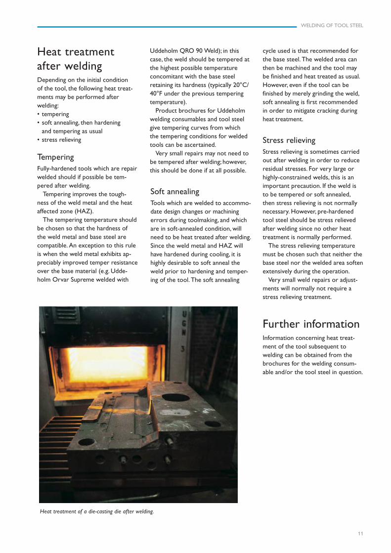
Heat treatment of a die-casting die after welding.
Soft annealingTools which are welded to accommo-date design changes or machiningerrors during toolmaking, and whichare in soft-annealed condition, willneed to be heat treated after welding.Since the weld metal and HAZ willhave hardened during cooling, it ishighly desirable to soft anneal theweld prior to hardening and temper-ing of the tool. The soft annealing
Uddeholm QRO 90 Weld); in thiscase, the weld should be tempered atthe highest possible temperatureconcomitant with the base steelretaining its hardness (typically 20°C/40°F under the previous temperingtemperature).
Product brochures for Uddeholmwelding consumables and tool steelgive tempering curves from whichthe tempering conditions for weldedtools can be ascertained.
Very small repairs may not need tobe tempered after welding; however,this should be done if at all possible.
12
WELDING OF TOOL STEEL

WELDING OF TOOL STEEL
13
WELDING IN HOT WORK TOOL STEEL – MMA (SMAW)
Guidelines for welding in Uddeholm tool steelThe tables, on following pages, give details concerning weld repair or adjustment of tooling made fromUddeholm steel grades for hot work, cold work and plastic moulding applications.
Soft annealing, seeproduct brochure
Temper hardenedmaterial 10–20°C(20–40°F) below lasttempering temperature
UDDEHOLM WELDING PREHEATING HARDNESS POSTSTEEL GRADE CONDITION METHOD CONSUMABLES TEMPERATURE AS WELDED TREATMENT REMARKS
VIDAR SUPERIORVIDAR 1 Soft annealed MMA QRO 90 WELD Min. 48–53 HRC Soft annealing
VIDAR 1 ESR Hardened (SMAW) UTP 673 325°C (620°F) 55–58 HRC Tempering
ORVAR SUPREMEORVAR SUPERIOR
ORVAR 2 Soft annealed MMA QRO 90 WELD Min. 48–53 HRC Soft annealing MICRODIZED Hardened (SMAW) UTP 673 325°C (620°F) 55–58 HRC Tempering
Soft annealed MMA Min. Soft annealing
DIEVAR Hardened (SMAW) QRO 90 WELD 325°C (620°F) 48–53 HRC Tempering
QRO 90 SUPREME Soft annealed MMA Soft annealing
HOTVAR Hardened (SMAW) QRO 90 WELD 325°C (620°F) 48–53 HRC Tempering
ALVAR MMA UTP 73 G4 225–275°C Stress relieve largeALVAR 14 Prehardened (SMAW) ESAB OK 83.28 (430–520°F) 340–390 HB None repairs
WELDING IN HOT WORK TOOL STEEL – TIG (GTAW)
UDDEHOLM WELDING PREHEATING HARDNESS POSTSTEEL GRADE CONDITION METHOD CONSUMABLES TEMPERATURE AS WELDED TREATMENT REMARKS
VIDAR SUPERIORVIDAR 1 Soft annealed TIG QRO 90 TIG WELD Min. Soft annealing
VIDAR 1 ESR Hardened (GTAW) DIEVAR TIG WELD 325°C (620°F) 48–53 HRC Tempering
Soft annealed TIG QRO 90 TIG WELD Min. Soft annealingHardned (GTAW) DIEVAR TIG WELD 325°C (620°F) 48–53 HRC Tempering
DIEVAR Temper 250°CLASER LASER WELD None 48–53 HRC (480°F) 2 h
Soft annealed TIG DIEVAR TIG WELD Min. Soft annealingHardened (GTAW) QRO 90 TIG WELD 325°C (620°F) 48–53 HRC Tempering
DIEVAR Temper 250°CDIEVAR LASER LASER WELD None 48–53 HRC (480°F) 2 h
QRO 90 SUPREME Soft annealed TIG Soft annealingHOTVAR Hardened (GTAW) QRO 90 TIG WELD 325°C (620°F) 48–53 HRC Tempering
UTP A 73 G4ALVAR TIG ESAB OK TIG ROD 225–275°C Stress relieve largeALVAR 14 Prehardened (GTAW) 13.22 (430–520°F) 340–390 HB None repairs
Soft annealing, seeproduct brochure
Temper hardenedmaterial 10–20°C(20–40°F) belowlasttemperingtemperature
ORVAR SUPREMEORVAR SUPERIORORVAR 2 MICRODIZED
14
WELDING OF TOOL STEEL
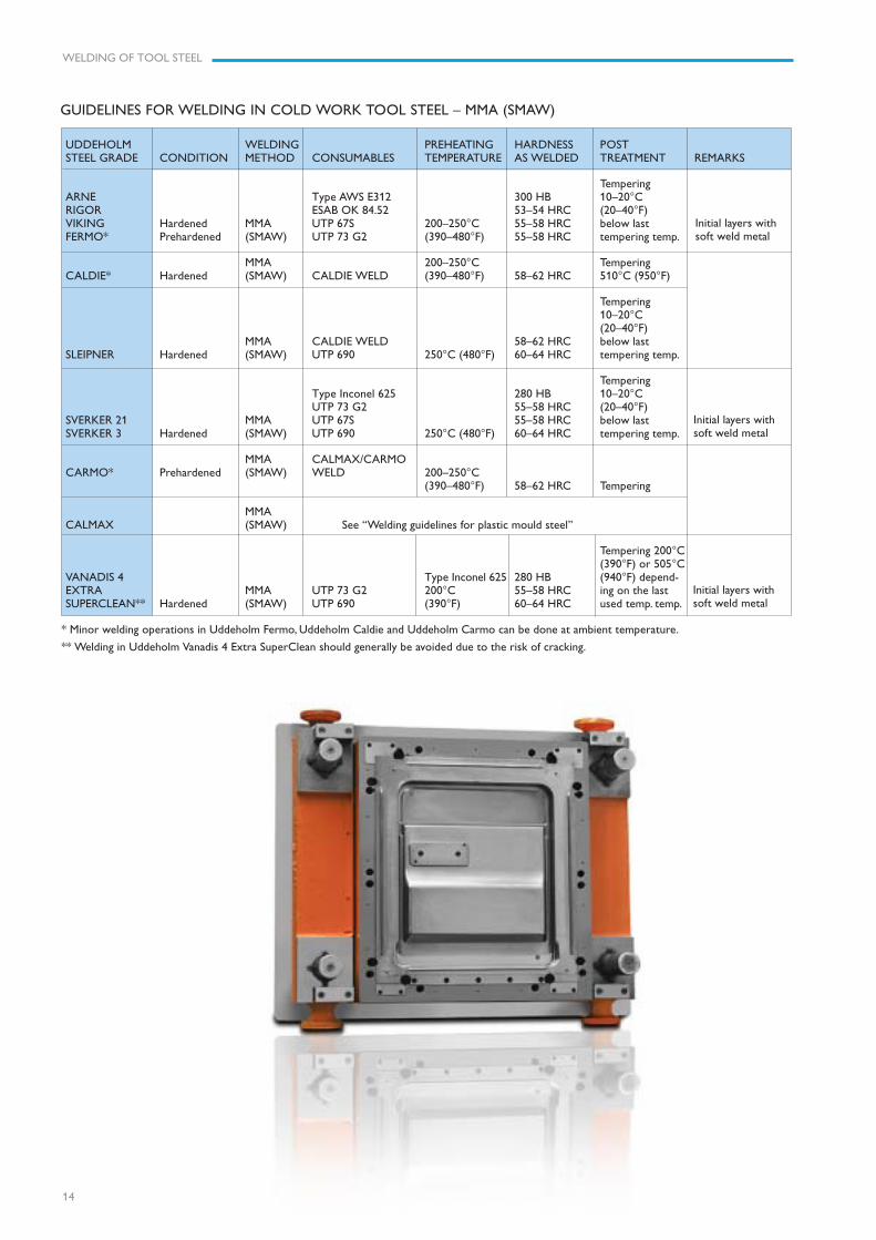
GUIDELINES FOR WELDING IN COLD WORK TOOL STEEL – MMA (SMAW)
Initial layers withsoft weld metal
Initial layers withsoft weld metal
Initial layers withsoft weld metal
UDDEHOLM WELDING PREHEATING HARDNESS POSTSTEEL GRADE CONDITION METHOD CONSUMABLES TEMPERATURE AS WELDED TREATMENT REMARKS
TemperingARNE Type AWS E312 300 HB 10–20°CRIGOR ESAB OK 84.52 53–54 HRC (20–40°F)VIKING Hardened MMA UTP 67S 200–250°C 55–58 HRC below lastFERMO* Prehardened (SMAW) UTP 73 G2 (390–480°F) 55–58 HRC tempering temp.
MMA 200–250°C TemperingCALDIE* Hardened (SMAW) CALDIE WELD (390–480°F) 58–62 HRC 510°C (950°F)
Tempering10–20°C(20–40°F)
MMA CALDIE WELD 58–62 HRC below lastSLEIPNER Hardened (SMAW) UTP 690 250°C (480°F) 60–64 HRC tempering temp.
TemperingType Inconel 625 280 HB 10–20°CUTP 73 G2 55–58 HRC (20–40°F)
SVERKER 21 MMA UTP 67S 55–58 HRC below lastSVERKER 3 Hardened (SMAW) UTP 690 250°C (480°F) 60–64 HRC tempering temp.
MMA CALMAX/CARMOCARMO* Prehardened (SMAW) WELD 200–250°C
(390–480°F) 58–62 HRC Tempering
MMACALMAX (SMAW) See “Welding guidelines for plastic mould steel”
Tempering 200°C(390°F) or 505°C
VANADIS 4 Type Inconel 625 280 HB (940°F) depend-EXTRA MMA UTP 73 G2 200°C 55–58 HRC ing on the lastSUPERCLEAN** Hardened (SMAW) UTP 690 (390°F) 60–64 HRC used temp. temp.
* Minor welding operations in Uddeholm Fermo, Uddeholm Caldie and Uddeholm Carmo can be done at ambient temperature.
** Welding in Uddeholm Vanadis 4 Extra SuperClean should generally be avoided due to the risk of cracking.

WELDING OF TOOL STEEL
15
Initial layers withsoft weld metal
Initial layers withsoft weld metal
Initial layers withsoft weld metal
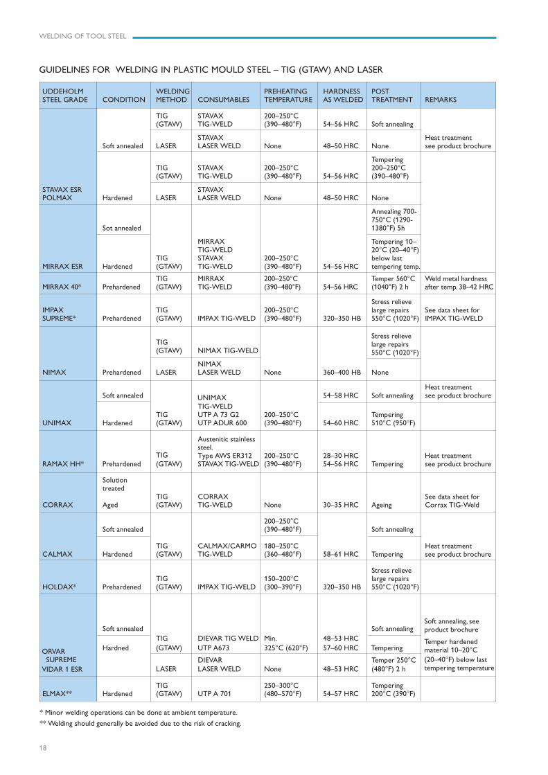
GUIDELINES FOR WELDING IN COLD WORK TOOL STEEL – TIG (GTAW)
UDDEHOLM WELDING PREHEATING HARDNESS POSTSTEEL GRADE CONDITION METHOD CONSUMABLES TEMPERATURE AS WELDED TREATMENT REMARKS
ARNE TemperingRIGOR Type AWS ER312 300 HB 10–20°CVIKING Hardened TIG UTP ADUR 600 200–250°C 55–58 HRC below lastFERMO* Prehardened (GTAW) UTP A 73 G2 (390–480°F) 53–56 HRC tempering temp.
TIG 200–250°C TemperingCALDIE* Hardened (GTAW) CALDIE TIG-WELD (390–480°F) 58–62 HRC 510°C (950°F)
Tempering10–20°C(20–40°F)
TIG CALDIE TIG-WELD 58–62 HRC below lastSLEIPNER Hardened (GTAW) UTP A 696 250°C (480°F) 60–64 HRC tempering temp.
TemperingType Inconel 625 280 HB 10–20°CUTP A 73 G2 53–56 HRC (20–40°F)
SVERKER 21 TIG UTP ADUR 600 55–58 HRC below lastSVERKER 3 Hardened (GTAW) UTP A 696 250°C (480°F) 60–64 HRC tempering temp.
TIG CALMAX/CARMOCARMO* Prehardened (GTAW) TIG WELD 200–250°C
(390–480°F) 58–62 HRC Tempering
TIGCALMAX (GTAW) See “Welding guidelines for plastic mould steel”
Tempering 200°C(390°F) or 505°C
VANADIS 4 Type Inconel 625 280 HB (940°F) depend-EXTRA TIG UTP A 73 G2 200°C 53–56 HRC ing on the lastSUPERCLEAN** Hardened (GTAW) UTP 696 (390°F) 60–64 HRC used temp. temp.
* Minor welding operations in Uddeholm Fermo, Uddeholm Caldie and Uddeholm Carmo can be done at ambient temperature.
** Welding in Uddeholm Vanadis 4 Extra SuperClean should generally be avoided due to the risk of cracking.
16
WELDING OF TOOL STEEL
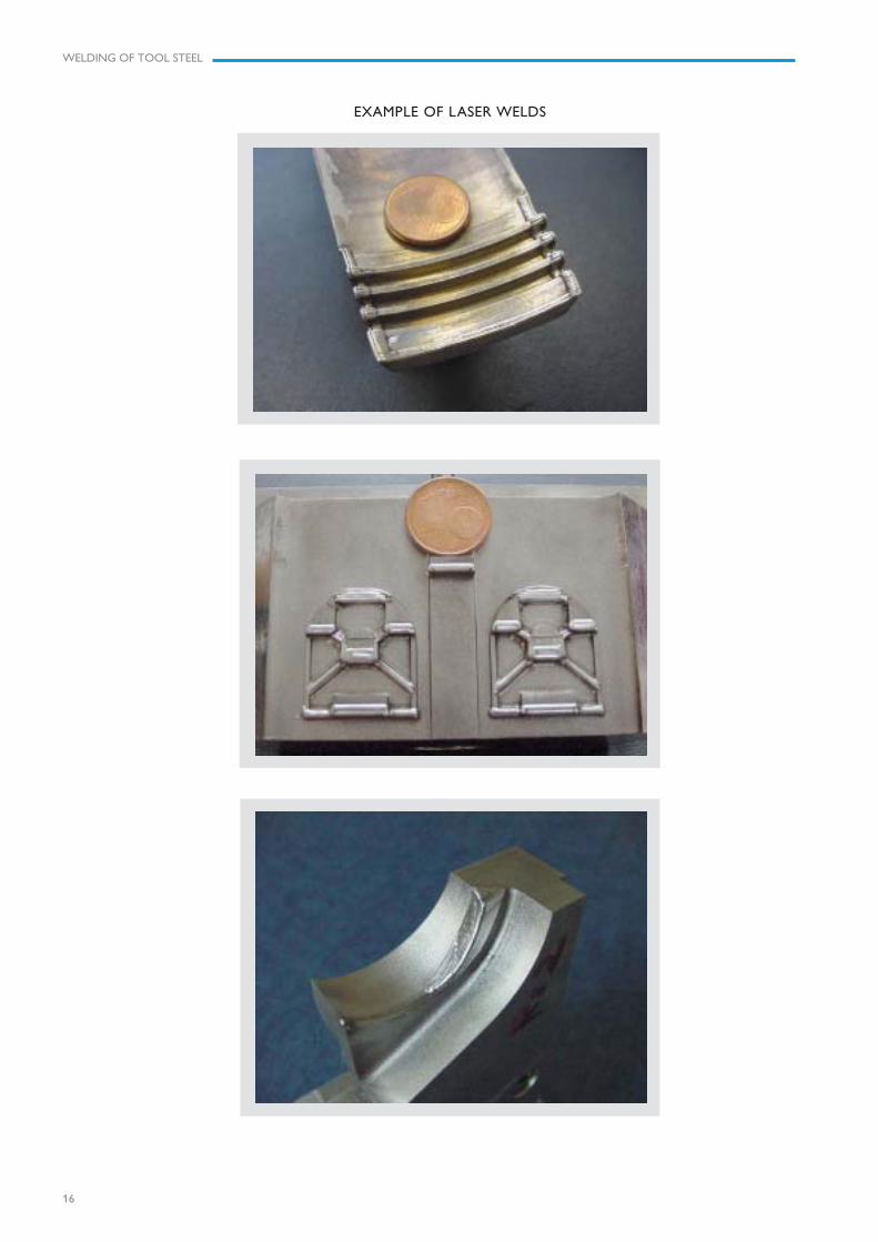
EXAMPLE OF LASER WELDS

WELDING OF TOOL STEEL
17
GUIDELINES FOR WELDING IN PLASTIC MOULD STEEL – MMA (SMAW)
Soft annealing, seeproduct brochure.Temper hardenedmaterial 10–20°C(20–40°F) below lasttempering temperature
UDDEHOLM WELDING PREHEATING HARDNESS POSTSTEEL GRADE CONDITION METHOD CONSUMABLES TEMPERATURE AS WELDED TREATMENT REMARKS
Stress relieveIMPAX MMA 200–250°C large repairsSUPREME* Prehardened (SMAW) IMPAX WELD (390–480°F) 320–350 HB 550°C (1020°F)
Heat treatmentSoft annealed Soft annealing see product brochure
MMA UTP 73 G2 200–250°C TemperingUNIMAX Hardened (SMAW) UTP 67 S (390–480°F) 55–58 HRC 510°C (950°F)
Austenitic stainlessMMA steel 200–250°C
RAMAX HH* Prehardened (SMAW) Type AWS E312 (390–480°F) 28–30 HRC Tempering
200–250°CSoft annealed (390–480°F) Soft annealing
MMA CALMAX/CARMO 180–250°C Heat treatmentCALMAX Hardened (SMAW) WELD (360–480°F) 59–62 HRC Tempering see product brochure
Stress relieveMMA 150–200°C large repairs
HOLDAX* Prehardened (SMAW) IMPAX WELD (300–390°F) 320–350 HB 550°C (1020°F)
ORVAR Soft annealed Soft annealing SUPREME MMA Min.
VIDAR 1 ESR Hardened (SMAW) UTP 673 325°C (620°F) 55–58 HRC Tempering
MMA Type Inconel 625 250–300°C 280 HB TemperingELMAX** Hardened (SMAW) UTP 701 (480–570°F) 54–57 HRC 200°C (390°F)
* Minor welding operations can be done at ambient temperature.
** Welding should generally be avoided due to the risk of cracking.

www.assab.com www.uddeholm.com
Network of excellenceUDDEHOLM is present on every continent. This ensures you
high-quality Swedish tool steel and local support wherever you
are. ASSAB is our exclusive sales channel, representing Uddeholm
in various parts of the world. Together we secure our position as
the world’s leading supplier of tooling materials.
UD
DEH
OLM
R-140218
UDDEHOLM is the world’s leading supplier of tooling materials. This
is a position we have reached by improving our customers’ everyday
business. Long tradition combined with research and product develop-
ment equips Uddeholm to solve any tooling problem that may arise.
It is a challenging process, but the goal is clear – to be your number one
partner and tool steel provider.
Our presence on every continent guarantees you the same high quality
wherever you are. ASSAB is our exclusive sales channel, representing
Uddeholm in various parts of the world. Together we secure our
position as the world’s leading supplier of tooling materials. We act
worldwide, so there is always an Uddeholm or ASSAB representative
close at hand to give local advice and support. For us it is all a matter of
trust – in long-term partnerships as well as in developing new products.
Trust is something you earn, every day.
For more information, please visit www.uddeholm.com, www.assab.com
or your local website.