what is isogeometric analysis? - sintef · what is isogeometric analysis? carlo lovadina,...
TRANSCRIPT
What is Isogeometric Analysis?
Carlo Lovadina, Alessandro Reali, Giancarlo Sangalli University of Pavia and IMATI-CNR of Pavia
Milan, June 30, 2014
TERRIFIC European Community’s Seventh Framework Programme
Grant Agreement 284981 Call FP7-2011-NMP-ICT-FoF

Isogeometric Analysis (IGA):
RECENT EMERGING technology for Scientifc Computing, stemming from
OLD ideas
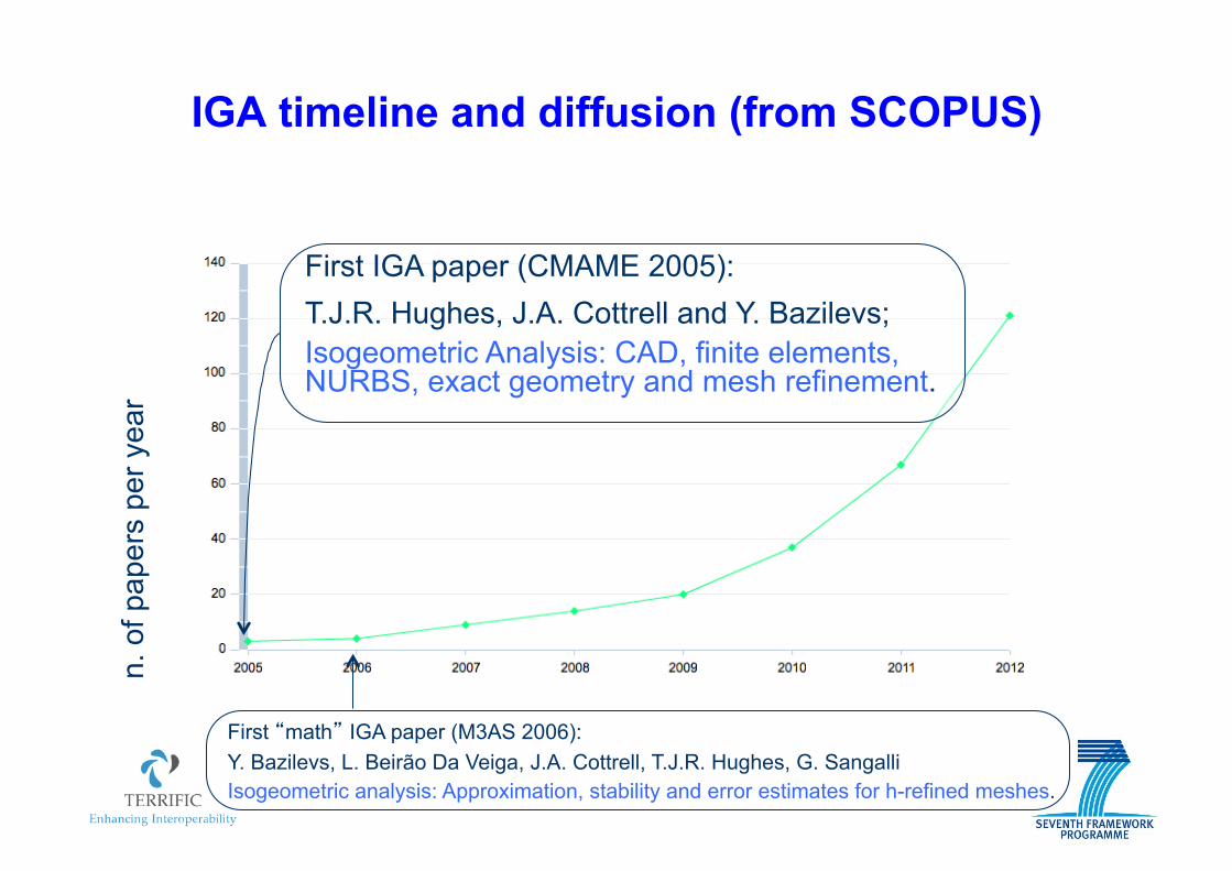
IGA timeline and diffusion (from SCOPUS)
First IGA paper (CMAME 2005): T.J.R. Hughes, J.A. Cottrell and Y. Bazilevs; Isogeometric Analysis: CAD, finite elements, NURBS, exact geometry and mesh refinement.
First “math” IGA paper (M3AS 2006): Y. Bazilevs, L. Beirão Da Veiga, J.A. Cottrell, T.J.R. Hughes, G. Sangalli Isogeometric analysis: Approximation, stability and error estimates for h-refined meshes.
n. o
f pap
ers
per y
ear
CAD (1970’s - 1980’s) – Engineering Design Process:
! engineering designs are encapsulated in CAD systems; ! CAD geometry is exact; ! hundreds of thousands analyses of CAD designs are performed
in engineering offices throughout the world every day
! CAD geometry is replaced by FEM geometry (“mesh”); ! mesh generation accounts for more than 80% of overall analysis time
and is the major bottleneck; ! mesh refinement requires interaction with CAD geometry; ! the mesh is an approximate geometry
FEM (1950’s - 1960’s) – Engineering Analysis Process:
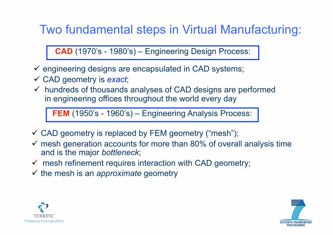
Two fundamental steps in Virtual Manufacturing:
CAD (1970’s - 1980’s) – Engineering Design Process:
! engineering designs are encapsulated in CAD systems; ! CAD geometry is exact; ! hundreds of thousands analyses of CAD designs are performed
in engineering offices throughout the world every day
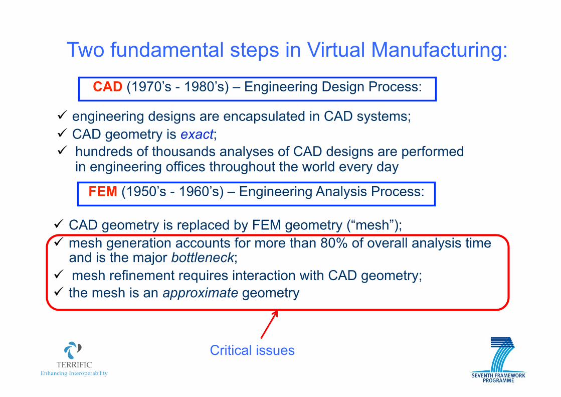
! CAD geometry is replaced by FEM geometry (“mesh”); ! mesh generation accounts for more than 80% of overall analysis time
and is the major bottleneck; ! mesh refinement requires interaction with CAD geometry; ! the mesh is an approximate geometry
FEM (1950’s - 1960’s) – Engineering Analysis Process:
Two fundamental steps in Virtual Manufacturing:
Critical issues
6
IDEA (Hughes et al., 2005): Isogeometric Analysis
In the Analysis framework, employ the same functions used to describe the geometry of the computational domain, i.e., typically, use B-Splines and Non-Uniform B-Splines (NURBS).
7
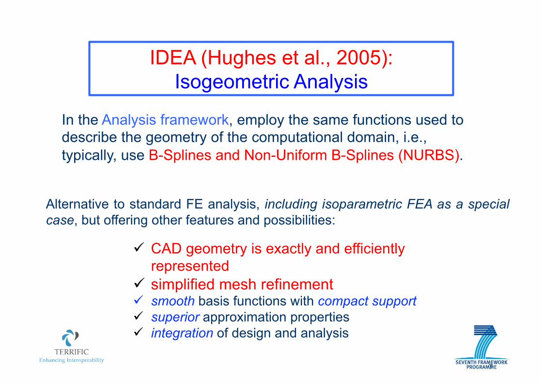
IDEA (Hughes et al., 2005): Isogeometric Analysis
In the Analysis framework, employ the same functions used to describe the geometry of the computational domain, i.e., typically, use B-Splines and Non-Uniform B-Splines (NURBS).
Alternative to standard FE analysis, including isoparametric FEA as a special case, but offering other features and possibilities:
! CAD geometry is exactly and efficiently represented
! simplified mesh refinement ! smooth basis functions with compact support ! superior approximation properties ! integration of design and analysis
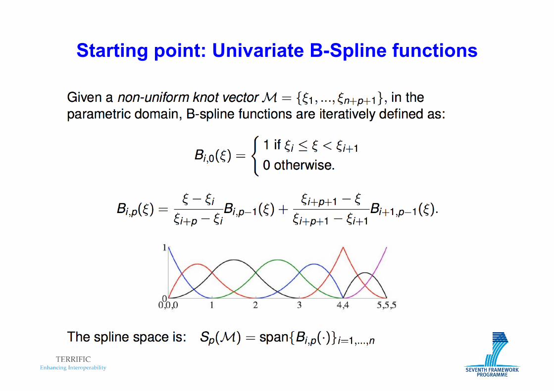
Starting point: Univariate B-Spline functions
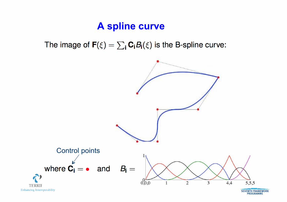
A spline curve
Control points
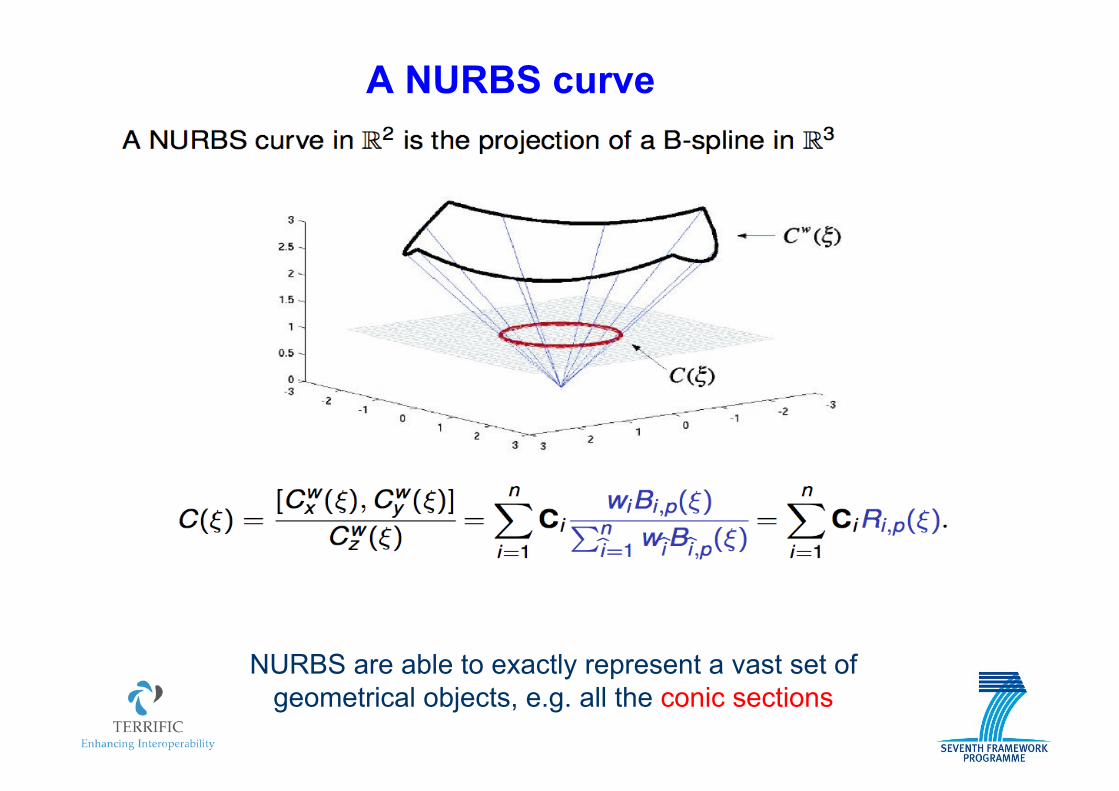
A NURBS curve
NURBS are able to exactly represent a vast set of geometrical objects, e.g. all the conic sections
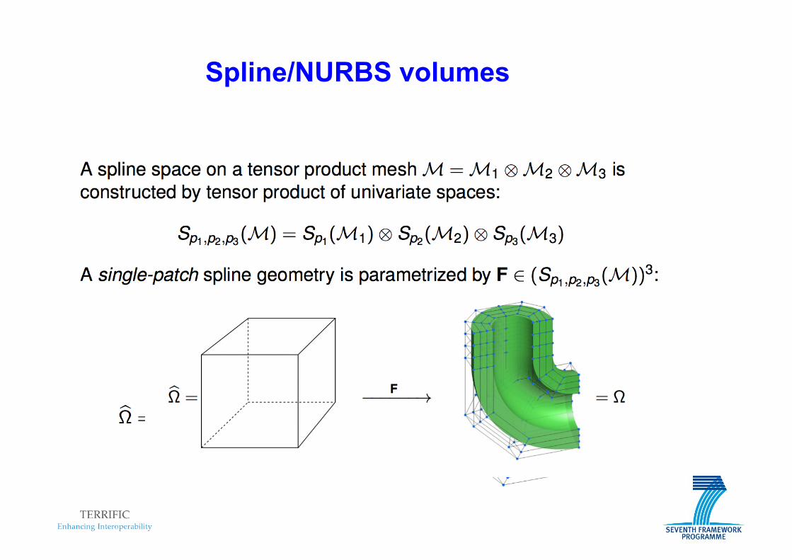
Spline/NURBS volumes

Spline/NURBS multi-patch volumes
Multi-patch geometries are typical in real-world applications
from T.J.R. Hughes group
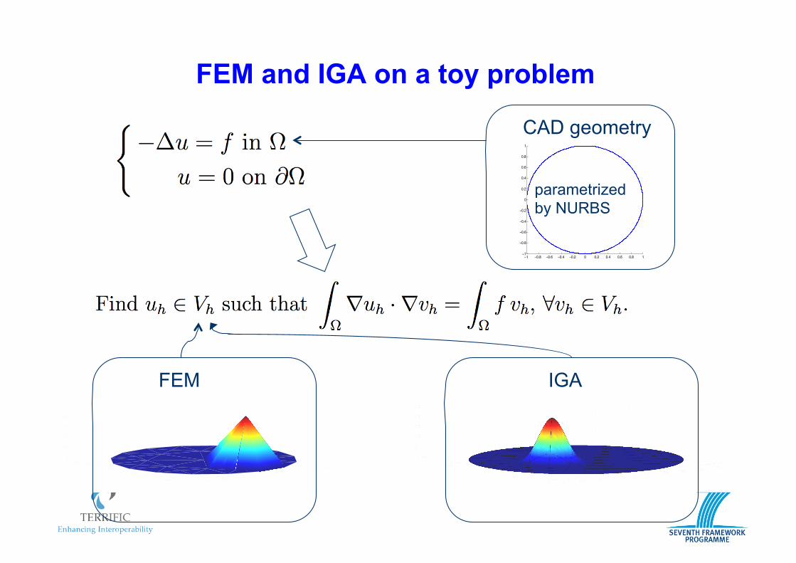
FEM and IGA on a toy problem
−1 −0.8 −0.6 −0.4 −0.2 0 0.2 0.4 0.6 0.8 1
−1−0.8
−0.6−0.4
−0.20
0.20.4
0.60.8
10
0.1
0.2
0.3
0.4
0.5
−1 −0.8 −0.6 −0.4 −0.2 0 0.2 0.4 0.6 0.8 1
−1−0.8
−0.6−0.4
−0.20
0.20.4
0.60.8
10
0.2
0.4
0.6
0.8
1
−1 −0.8 −0.6 −0.4 −0.2 0 0.2 0.4 0.6 0.8 1
−1−0.8−0.6−0.4−0.200.20.40.60.810
0.1
0.2
0.3
0.4
0.5
−1 −0.8 −0.6 −0.4 −0.2 0 0.2 0.4 0.6 0.8 1−1
−0.8
−0.6
−0.4
−0.2
0
0.2
0.4
0.6
0.8
1
CAD geometry
FEM IGA
parametrized by NURBS
14
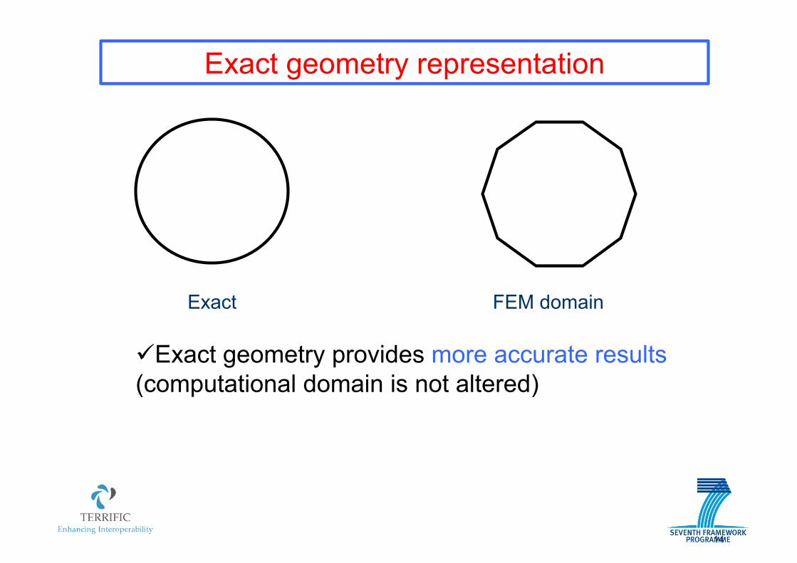
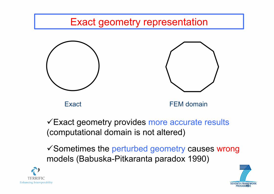
Exact geometry representation
Exact FEM domain
! Exact geometry provides more accurate results (computational domain is not altered)
15
Exact geometry representation
Exact FEM domain
! Exact geometry provides more accurate results (computational domain is not altered)
! Sometimes the perturbed geometry causes wrong models (Babuska-Pitkaranta paradox 1990)
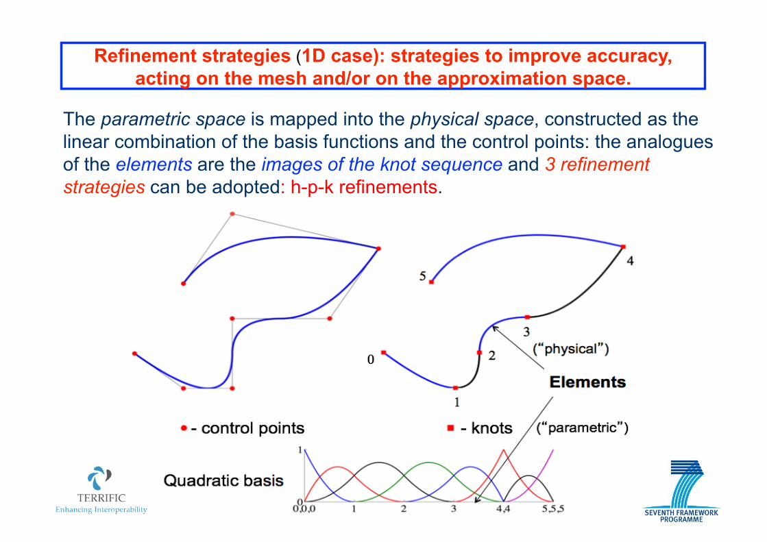
Refinement strategies (1D case): strategies to improve accuracy, acting on the mesh and/or on the approximation space.
The parametric space is mapped into the physical space, constructed as the linear combination of the basis functions and the control points: the analogues of the elements are the images of the knot sequence and 3 refinement strategies can be adopted: h-p-k refinements.
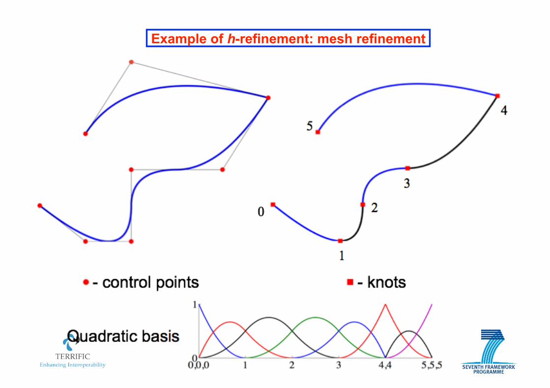
Example of h-refinement: mesh refinement
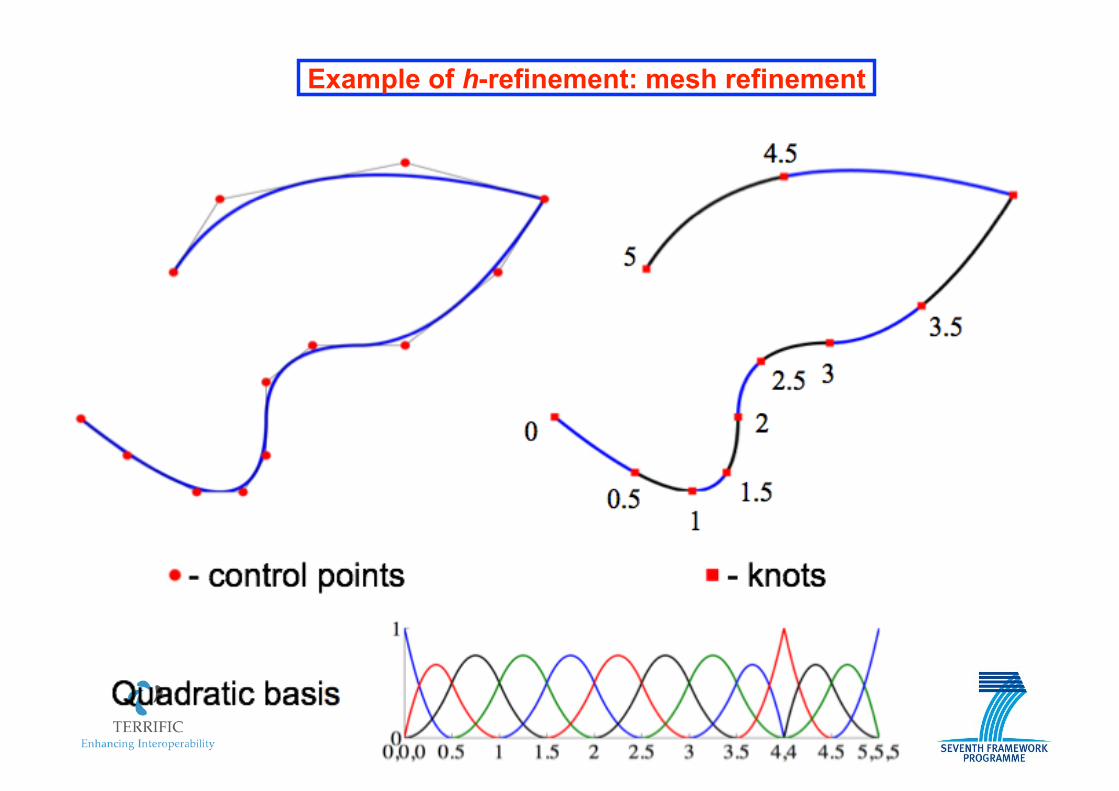
Example of h-refinement: mesh refinement

Example of h-refinement: mesh refinement
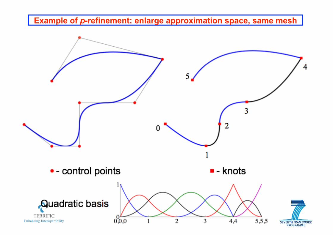
Example of p-refinement: enlarge approximation space, same mesh
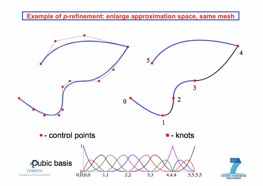
Example of p-refinement: enlarge approximation space, same mesh
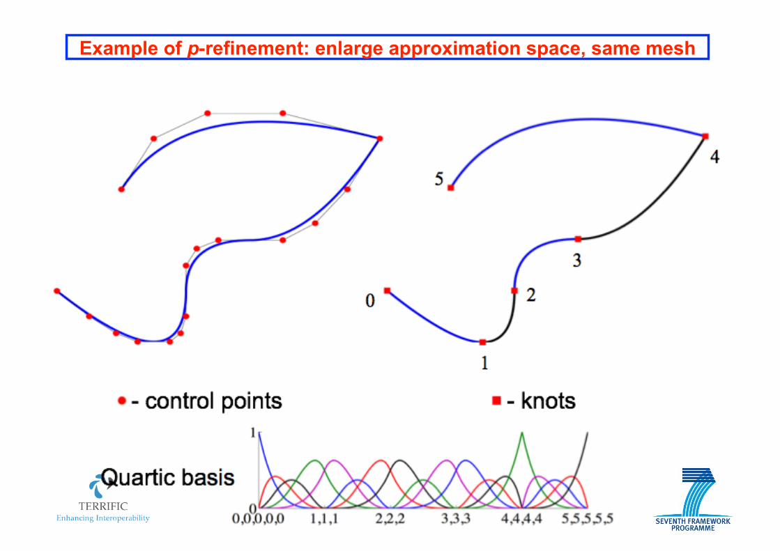
Example of p-refinement: enlarge approximation space, same mesh
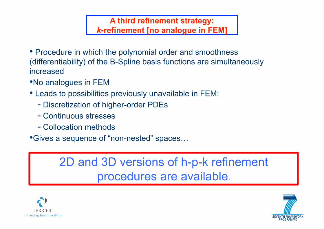
A third refinement strategy: k-refinement [no analogue in FEM]
• Procedure in which the polynomial order and smoothness (differentiability) of the B-Spline basis functions are simultaneously increased • No analogues in FEM • Leads to possibilities previously unavailable in FEM:
- Discretization of higher-order PDEs - Continuous stresses - Collocation methods
• Gives a sequence of “non-nested” spaces…
2D and 3D versions of h-p-k refinement procedures are available.

Implementation
Flowchart of a classical finite element code. Such a code can be converted to a single-patch isogeometric analysis code by replacing the routines shown in green.
[Cottrell et al., 2009]
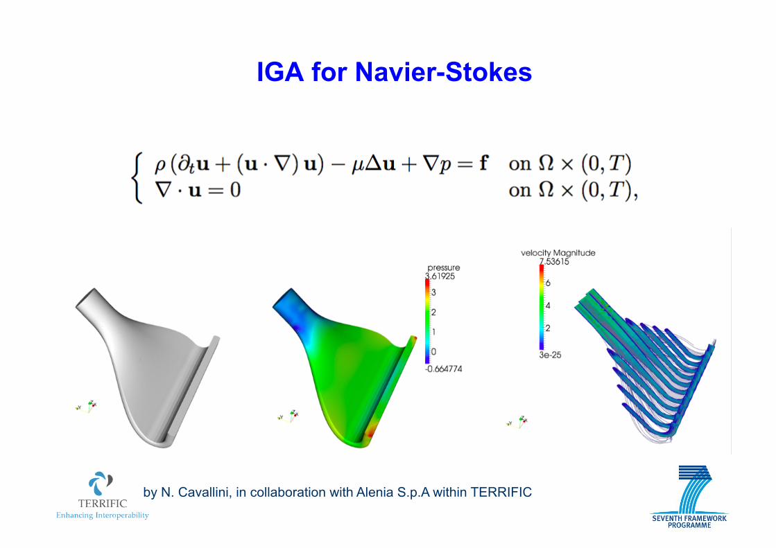
IGA for Navier-Stokes
by N. Cavallini, in collaboration with Alenia S.p.A within TERRIFIC

26
Pressure profile: IGA Pressure profile: FEM
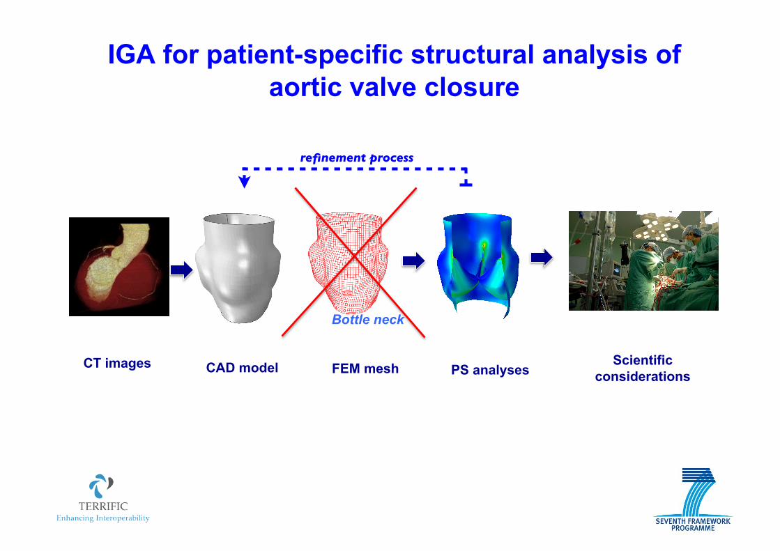
CT images CAD model FEM mesh PS analyses Scientific
considerations
refinement process
Bottle neck
IGA for patient-specific structural analysis of aortic valve closure
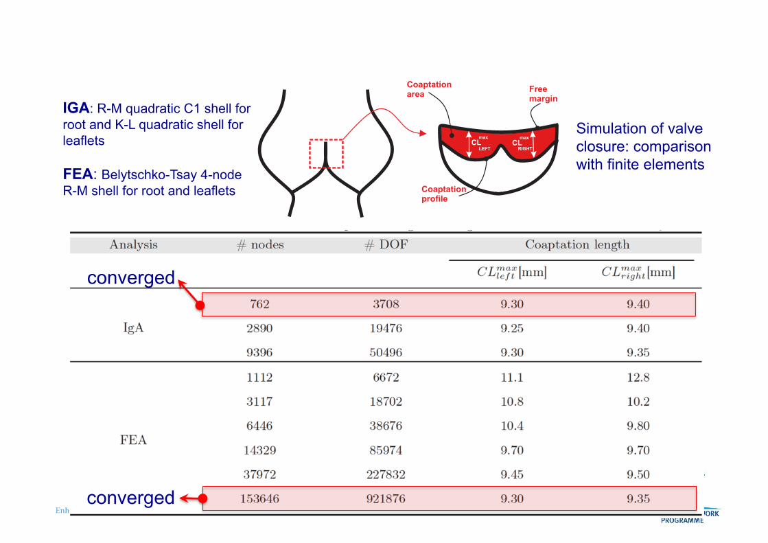
Coaptationarea
(a)
Freemargin
Coaptationprofile
CLLEFT
max
CLRIGHT
maxSimulation of valve closure: comparison with finite elements
IGA: R-M quadratic C1 shell for root and K-L quadratic shell for leaflets
FEA: Belytschko-Tsay 4-node R-M shell for root and leaflets
converged
converged
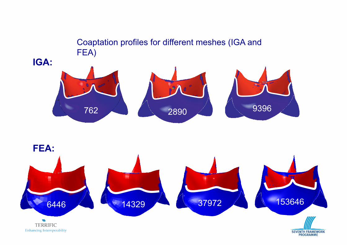
Coaptation profiles for different meshes (IGA and FEA)
(a) (b) (c)
IGA:
FEA:
762 2890 9396
6446 14329 37972 153646
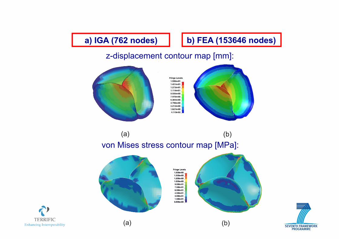
a) IGA (762 nodes) b) FEA (153646 nodes)
z-displacement contour map [mm]:
von Mises stress contour map [MPa]:
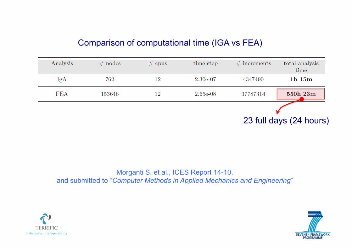
Comparison of computational time (IGA vs FEA)
23 full days (24 hours)
Morganti S. et al., ICES Report 14-10, and submitted to “Computer Methods in Applied Mechanics and Engineering”
CONCLUSIONS
Isogeometric Analysis is an emerging technology capable of:
" Directly interacting wtih the CAD systems " Greatly simplifying the refinement processes " Improving the solution accuracy " Reducing the computational costs
CONCLUSIONS
Isogeometric Analysis is an emerging technology capable of:
" Directly interacting wtih the CAD systems " Greatly simplifying the refinement processes " Improving the solution accuracy " Reducing the computational costs
If your applications demand high level quality…
CONCLUSIONS
Isogeometric Analysis is an emerging technology capable of:
" Directly interacting wtih the CAD systems " Greatly simplifying the refinement processes " Improving the solution accuracy " Reducing the computational costs
If your applications demand high level quality…
TRY IT ! ! !