what is robust design or taguchi’s method? an experimental method to achieve product and process...
Post on 21-Dec-2015
214 views
TRANSCRIPT

What is Robust Design or Taguchi’s method?
• An experimental method to achieve product and process quality through designing in an insensitivity to noise based on statistical principles.

History of the method
• Dr. Taguchi in Japan: 1949-NTT– develops “Quality Engineering”
– 4 time winner of Demming Award
• Ford Supplier Institute, early 1980s
• American Supplier Institute, ASI– Engineering Hall of Fame
• Statistics Community– DOE
– S/N Ratio

Who uses Taguchi’s Methods
• Lucent• Ford• Kodak• Xerox• Whirlpool• JPL• ITT
• Toyota• TRW• Chrysler• GTE• John Deere• Honeywell• Black & Decker

Documented Results from Use
• 96% improvement of NiCAD battery on satellites (JPL/ NASA)
• 10% size reduction, 80% development time reduction and 20% cost reduction in design of a choke for a microwave oven (L.G. Electronics)
• $50,000 annual cost savings in design of heat staking process (Ann Arbor Assembly Corp)
• 60% reduction in mean response time for computer system (Lucent)
• $900,000 annual savings in the production of sheet-molded compound parts (Chrysler)
• $1.2M annual savings due to reduction in vacuum line connector failures (Flex Technologies)
• 66% reduction in variability in arrival time and paper orientation (Xerox)
• 90% reduction in encapsulation variation (LSI Corp)
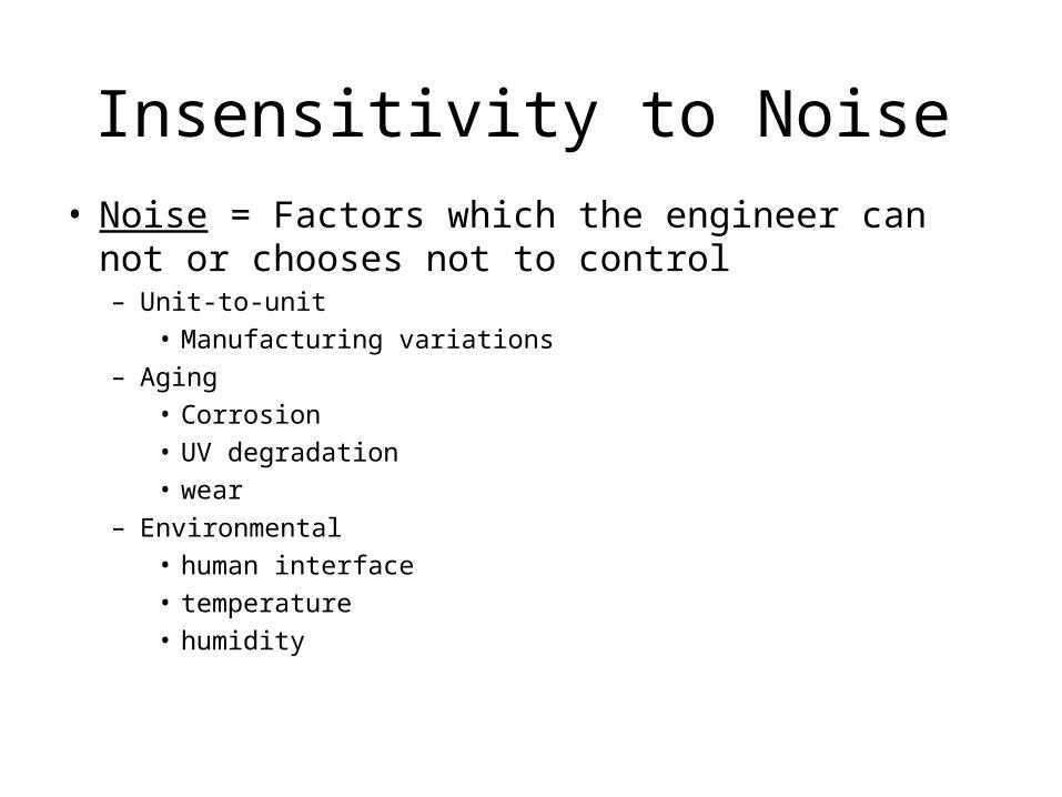
Insensitivity to Noise
• Noise = Factors which the engineer can not or chooses not to control– Unit-to-unit
• Manufacturing variations– Aging
• Corrosion• UV degradation• wear
– Environmental• human interface• temperature• humidity

How Noise Affects a System
Ideal Function ofProduct or Process
Noise
Control Factors
EnergyUseful EnergyQuality Characteristic, y
Harmful EnergyCaused by Noise
Signal Factor, M
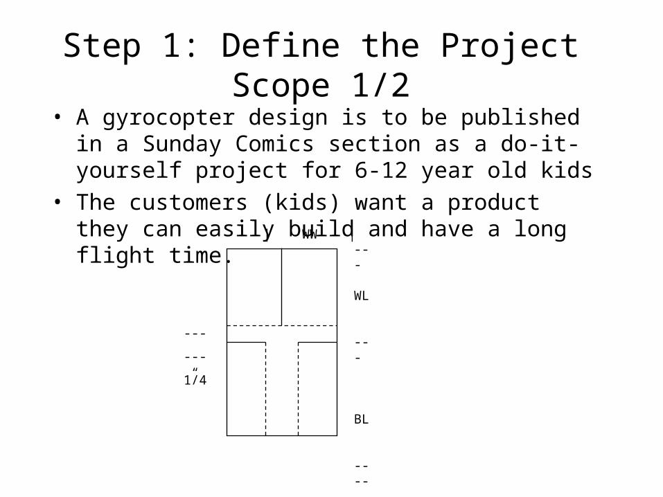
Step 1: Define the Project Scope 1/2
• A gyrocopter design is to be published in a Sunday Comics section as a do-it-yourself project for 6-12 year old kids
• The customers (kids) want a product they can easily build and have a long flight time.
| WW |---
WL
---
BL
----
--- --- 1/4”
Step 1: Define the Project Scope 2/2
• This is a difficult problem from an engineering standpoint because:
– hard to get intuitive feel for effect of control variables
– cant control materials, manufacturing or assembly
– noise factors are numerous and have strong effect on flight.
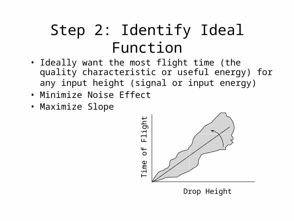
Step 2: Identify Ideal Function
• Ideally want the most flight time (the quality characteristic or useful energy) for any input height (signal or input energy)
• Minimize Noise Effect• Maximize Slope
Drop Height
Tim
e of
Fli
ght

Step 3: Develop Noise Strategy 1/2
• Goal is to excite worst possible noise conditions
• Noise factors– unit-to-unit
– aging
– environment

Step 3: Develop Noise Strategy 2/2
• Noise factors– unit-to-unit
Construction accuracy
Paper weight and type
angle of wings
– aging
damage from handling
– environment
angle of release
humidity content of air
wind
+ many, many others

Step 4: Establish Control Factors and Levels 1/4
• Want them independent to minimize interactions– Dimensionless variable methods help– Design of experiments help– Confirm effect of interactions in Step 7
• Want to cover design space– may have to guess initially and perform more
than one set of experiments. Method will help determine where to go next.
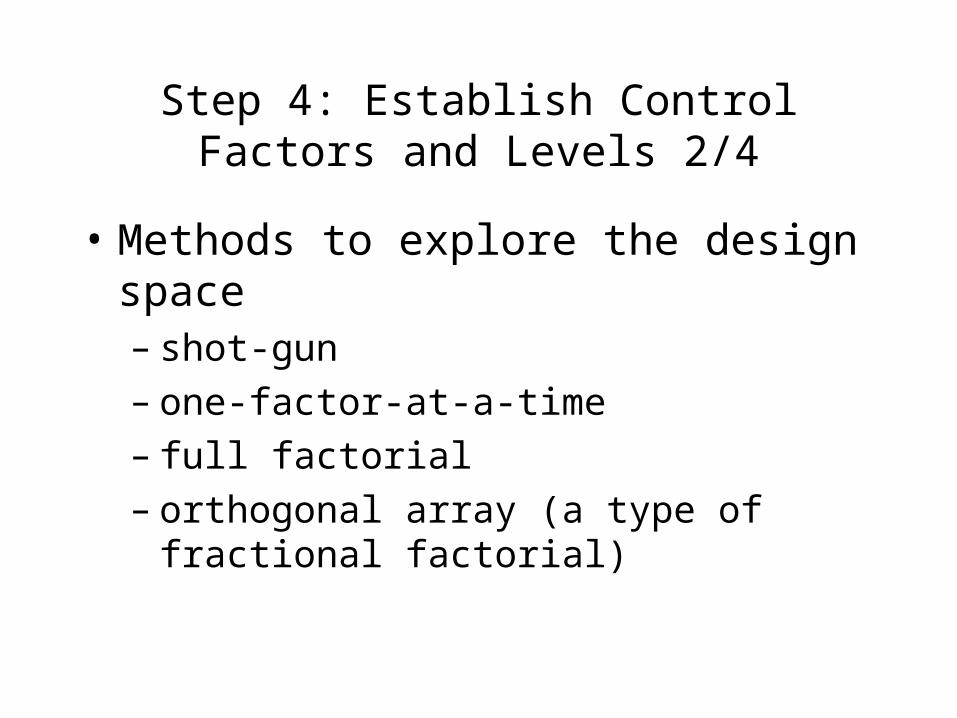
Step 4: Establish Control Factors and Levels 2/4
• Methods to explore the design space– shot-gun– one-factor-at-a-time – full factorial– orthogonal array (a type of fractional factorial)

Step 4: Establish Control Factors and Levels 3/4
Control factor array for the paper gyrocopter parameter optimizationexperiment
1 2 3 4 5 6 7 8Run WL WW BL Size B_Fold Gussets
1 1 1.0/ww 0.50 1.33 x WL 100% 1 0 None2 1 1.0/ww 0.75 1.67 x WL 75% 2 15% 45deg3 1 1.0/ww 1.00 2.00 x WL 50% 3 30% 45deg4 1 1 .5/ww 0.50 1.33 x WL 75% 2 30% 45deg5 1 1.5/ww 0.75 1.67 x WL 50% 3 0 None6 1 1.5/ww 1.00 2.00 x WL 100% 1 15% 45deg7 1 2.0/ww 0.50 1.67 x WL 100% 3 1 5% 45deg8 1 2.0/ww 0.75 2.00 x WL 75% 1 30% None9 1 2.0/ww 1.00 1.33 x WL 50% 2 0 45deg10 2 1.0/ww 0.50 2.00 x WL 50% 2 15% None11 2 1.0/ww 0.75 1.33 x WL 100% 3 30% 45deg12 2 1.0/ww 1.00 1.67 x WL 75% 1 0 45deg13 2 1.5/ww 0.50 1.67 x WL 50% 1 30% 45 deg14 2 1.5/ww 0.75 2.00 x WL 100% 2 0 45deg15 2 1.5/ww 1.00 1.33 x WL 75% 3 15% None16 2 2.0/ww 0.50 2.00 x WL 75% 3 0 45deg17 2 2.0/ww 0.75 1.33 x WL 50% 1 15% 45deg18 2 2.0/ww 1.00 1.67 x WL 100% 2 30% None

Step 4: Establish Control Factors and Levels 4/4
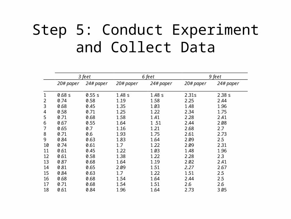
Step 5: Conduct Experiment and Collect Data
3 feet 6 feet 9 feet
20# paper 24# paper 20# paper 24# paper 20# paper 24# paper
1 0.68 s 0.55 s 1.48 s 1.48 s 2.31s 2.38 s2 0.74 0.58 1.19 1.58 2.25 2.443 0.68 0.45 1.35 1.03 1.48 1.964 0.58 0.71 1.25 1.22 2.34 1.755 0.71 0.68 1.58 1.41 2.28 2.416 0.67 0.55 1.64 1 .51 2.44 2.087 0.65 0.7 1.16 1.21 2.68 2.78 0.71 0.6 1.93 1.75 2.61 2.739 0.84 0.63 1.83 1.64 2.09 2.510 0.74 0.61 1.7 1.22 2.09 2.3111 0.61 0.45 1.22 1.03 1.48 1.9612 0.61 0.58 1.38 1.22 2.28 2.313 0.87 0.68 1.64 1.19 2.02 2.4114 0.81 0.65 2.09 1.51 2.27 2.6715 0.84 0.63 1.7 1.22 1.51 2.516 0.68 0.68 1.54 1.64 2.44 2.517 0.71 0.68 1.54 1.51 2.6 2.618 0.61 0.84 1.96 1.64 2.73 3.05

Data for Runs 5 and 15
0
0.5
1
1.5
2
2.5
0 2 4 6 8 10
Height (ft)
Tim
e (s
ec)
Run 5
Run 15

Step 6: Conduct Data Analysis 1/7
• Calculate signal-to-noise-ratio (S/N) and Mean• Complete and interpret response tables• Perform two step optimization
– Reduce Variability (minimize the S/N ratio)– Adjust the mean
• Make predictions about most robust configuration

Step 6: Conduct Data Analysis 2/7
• Calculate signal to noise ratio, S/N, a metric in decibels
Useful outputHarmful output
S/N =
Effect of MeanVariability around mean=
= 10 log y2
s2 Note: This is one of many forms of S/N ratios.
variabilityS/N gain reduction
3 27% 6 50% 12 75%
Step 6: Conduct Data Analysis 3/7
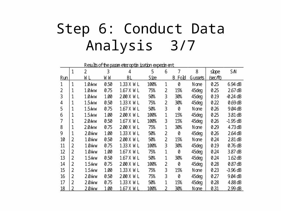
Results of the parameter optimization experiment1 2 3 4 5 6 7 8 slope S/N
Run WL WW BL Size B_Fold Gussets (sec/ft)1 1 1.0/ww 0.50 1.33 X WL 100% 1 0 None 0.25 6.94 dB2 1 1.0/ww 0.75 1.67 X WL 75% 2 15% 45deg 0.25 2.67 dB3 1 1.0/ww 1.00 2.00 X WL 50% 3 30% 45deg 0.19 -0.24 dB4 1 1.5/ww 0.50 1.33 X WL 75% 2 30% 45deg 0.22 0.69 dB5 1 1.5/ww 0.75 1.67 X WL 50% 3 0 None 0.26 9.04 dB6 1 1.5/ww 1.00 2.00 X WL 100% 1 15% 45deg 0.25 3.81 dB7 1 2.0/ww 0.50 1.67 X WL 100% 3 15% 45deg 0.26 -1.95 dB8 1 2.0/ww 0.75 2.00 X WL 75% 1 30% None 0.29 4.73 dB9 1 2.0/ww 1.00 1.33 X WL 50% 2 0 45deg 0.26 2.64 dB10 2 1.0/ww 0.50 2.00 X WL 50% 2 15% None 0.24 2.81 dB11 2 1.0/ww 0.75 1.33 X WL 100% 3 30% 45deg 0.19 0.76 dB12 2 1.0/ww 1.00 1.67 X WL 75% 1 0 45deg 0.24 3.87 dB13 2 1.5/ww 0.50 1.67 X WL 50% 1 30% 45deg 0.24 1.62 dB14 2 1.5/ww 0.75 2.00 X WL 100% 2 0 45deg 0.28 0.87 dB15 2 1.5/ww 1.00 1.33 X WL 75% 3 15% None 0.23 -3.96 dB16 2 2.0/ww 0.50 2.00 X WL 75% 3 0 45deg 0.27 9.04 dB17 2 2.0/ww 0.75 1.33 X WL 50% 1 15% 45deg 0.28 4.88 dB18 2 2.0/ww 1.00 1.67 X WL 100% 2 30% None 0.31 2.99 dB

Step 6: Conduct Data Analysis 4/7Response Table
Factor response averages table for theparameter optimization experimentFactor Time Time
Level (slope) (S/N)1.0/ww 0.23 2.80
WL 1.5/ww 0.25 2.012.0/ww 0.28 3.720.50 0.25 3.19
WW 0.75 0.26 3.821.00 0.25 1.521.33 X WL 0.24 1.99
BL 1.67 X WL 0.26 3.042.00 X WL 0.25 3.50100% 0.26 2.23
Size 75% 0.25 2.8450% 0.25 3.460% 0.26 5.40
B_Fold 15% 0.25 1.3830% 0.24 1.76
Gussets None 0.26 3.7645deg 0.25 2.39
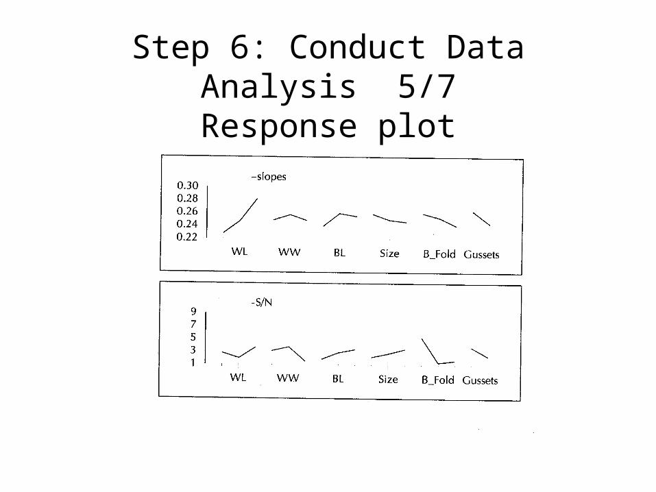
Step 6: Conduct Data Analysis 5/7Response plot

Step 6: Conduct Data Analysis 6/7Two Step Optimization
• Reduce Variability (minimize the S/N ratio)– look for control factor effects on S/N– Don’t worry about mean
• Adjust the mean– To get desired response– Use “adjusting factors”, those control factors
which have minimal effect on S/N
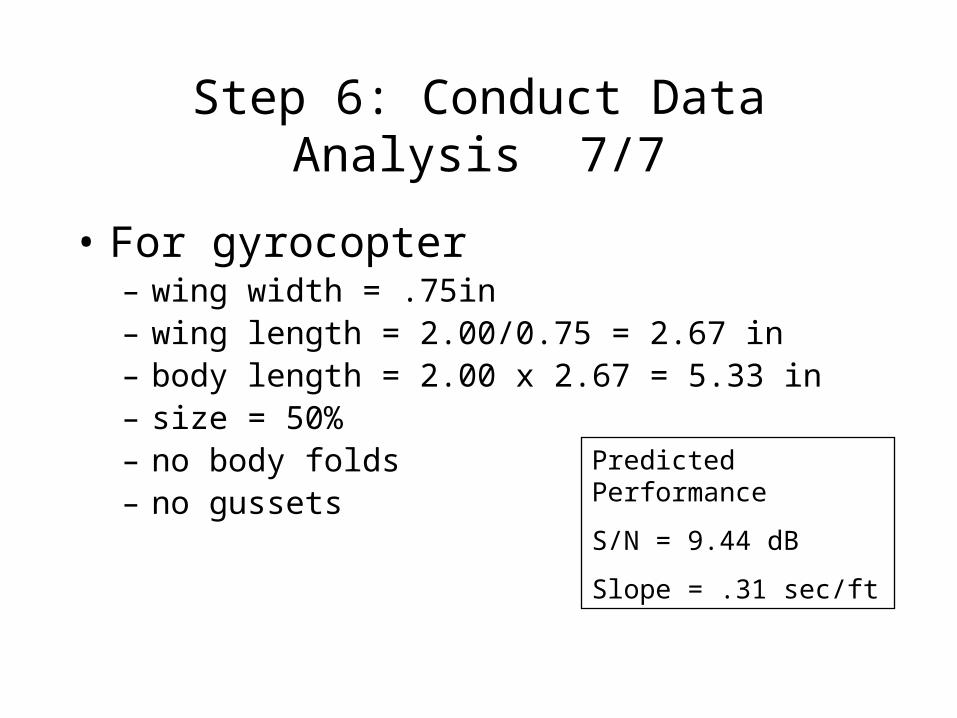
Step 6: Conduct Data Analysis 7/7
• For gyrocopter– wing width = .75in– wing length = 2.00/0.75 = 2.67 in– body length = 2.00 x 2.67 = 5.33 in– size = 50%– no body folds– no gussets
Predicted Performance
S/N = 9.44 dB
Slope = .31 sec/ft

Step 7: Conduct Conformation Run
• To check validity of results• To check for unforeseen interaction effects
between control factors• To check for unaccounted for noise factors• To check for experimental error
Predicted Confirmed
S/N 9.44 dB 9.86
Slope .31sec/ft .32 sec/ft

How Taguchi’s Method Differs from an Ad-hoc Design Process
• Organized Design Space Search
• Clear Critical Parameter Identification
• Focus on Parameter Variation (Noise)
• Clear Stopping Criteria
• Robustness centered not Failure Centered
• Reusable Method
• Concurrently Addresses Manufacturing Variation
• Concurrent Design-Test Not Design-Test-Fix
• Minimize Development Time (Stops Fire Fighting)
• Corporate Memory Through Documentation
• Encourages Technology Development Through System Understanding
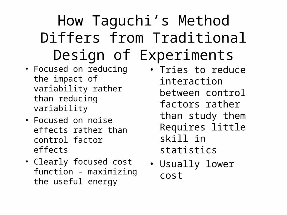
How Taguchi’s Method Differs from Traditional Design of Experiments
• Focused on reducing the impact of variability rather than reducing variability
• Focused on noise effects rather than control factor effects
• Clearly focused cost function - maximizing the useful energy
• Tries to reduce interaction between control factors rather than study them Requires little skill in statistics
• Usually lower cost

How Taguchi’s Method Differs from Shainin’s Method
• Focused on both Product and Process Design rather than Primarily on Process
• Oriented to developing a robust system not finding a problem (Red X). Taguchi tells what parameter values to set to make system insensitive to parameter Shainin identifies as needing control.
• Widely Used Internationally
• Fire prevention rather than fire fighting
• Accessible
• Many Case Studies Available

Plan for Application at Tektronix
• Select a parameter design problem • Design the experiment• Perform the experiment• Reduce data• Report results to Company• Assuming success
– design more experiments– train more engineers – Plan for student-run experiments