what’s new in fix 7 - feitelberg.net · proprietary notice the manual and software contain...
TRANSCRIPT

What’s New in FIX 7

Proprietary Notice
The manual and software contain confidential information which representstrade secrets of Intellution and/or its suppliers, and may not be copied ordisclosed except as provided in the license with Intellution. The informationin this manual is subject to change without notice and should not beconstrued as a commitment by Intellution, Inc. Intellution assumes noresponsibility for any errors that may be in this document.
© 1988-1997, 1999 Intellution®, Inc. All Rights Reserved.
TrademarksIntellution®, Intelligent Solutions®, Paradym-31®, and FIX® are registeredtrademarks of Intellution, Inc.
VisualBatch™, Intellution WorkSpace™, iCore™, and FIX Dynamics™are trademarks of Intellution, Inc.
All other brand or product names are trademarks or registered trademarks oftheir respective holders.
This document contains Year 2000 readiness disclosure information.
Version 7-03.99 INT12037.00
Intelligent Solutions

Contents iii
Table of Contents
1. WHAT’S NEW FOR FIX 7 ............................................................................................ 1
1.1 Full System Year 2000 Support.......................................................................... 1
1.1.1 Microsoft Windows NT 4.0 with Service Pack 4 .................................... 31.1.2 Microsoft Windows 98 ........................................................................... 3
1.2 Improved Historical Collection Capacity ............................................................. 4
1.3 Enhanced Security.............................................................................................. 4
1.3.1 Using Domain Names............................................................................ 51.3.2 Configuring a Stand-alone Node ........................................................... 6
1.4 OPC Client/Server Support................................................................................. 7
1.4.1 Using the OPC Server ........................................................................... 71.4.2 Using the OPC Client Driver .................................................................. 9
1.5 Suppressing Driver Communication Alarms....................................................... 9
1.6 Improved I/O Driver Support............................................................................. 10
1.7 Microsoft SQL Server 7.0 Support.................................................................... 10
2. FEATURES FROM V6.1.5 ......................................................................................... 11
2.1 Automatic Failover ............................................................................................ 11
2.1.1 Understanding the Automatic Failover Option..................................... 132.1.2 Configuring a View Node for Automatic Failover................................. 182.1.3 Changing your Network Protocol to TCP/IP ........................................ 19
2.2 Remote Historical Display................................................................................. 31
2.2.1 Why Use Remote Historical Display?.................................................. 312.2.2 Using Remote Historical Display ......................................................... 322.2.3 Using Remote Historical Paths in Pen Definitions............................... 342.2.4 Remote Historical Example ................................................................. 36
2.3 Tiling and Cascading Pictures in View.............................................................. 37
2.3.1 Providing Access to the Tile and Cascade Commands ...................... 39

iv What’s New for FIX 7
2.4 Multiple Picture Search and Replace Support.................................................. 40
2.4.1 Searching and Replacing Tagnames in Multiple Pictures ................... 40
2.5 Historical Tag Assign CSV File Import and Export ........................................... 44
2.5.1 Exporting a Collection Group File ........................................................ 452.5.2 Editing a CSV File................................................................................ 452.5.3 Importing a CSV File into Historical Trend Assign............................... 48
2.6 Background Scripts........................................................................................... 49
3. FEATURES FROM FIX 6.1 ........................................................................................ 51
3.1 New Command Language Editor...................................................................... 52
3.1.1 New Interface Design .......................................................................... 523.1.2 Command Buttons............................................................................... 533.1.3 Search and Replace ............................................................................ 583.1.4 Right Mouse Button Commands within the Command Editor
Environment......................................................................................... 603.1.5 Importing Existing Command Language Scripts ................................. 61
3.2 .DXF Picture Import .......................................................................................... 62
3.2.1 Using the Import Wizard ...................................................................... 64
3.3 Using the Right-Mouse Button.......................................................................... 67
3.4 Picture Types.................................................................................................... 67
3.4.1 Working with Standard Pictures and Subpictures ............................... 693.4.2 Working with Pop-Up Pictures............................................................. 723.4.3 Specifying the Picture Type................................................................. 743.4.4 Window Properties for Pictures ........................................................... 743.4.5 Selecting Window Properties for Pictures ........................................... 75
3.5 Saving Settings in DRAW................................................................................. 76
3.5.1 Color Threshold Settings ..................................................................... 763.5.2 Grid Settings ........................................................................................ 76
3.6 RESOLVEVARS Command ............................................................................. 77
3.7 Alarm Summary Enhancements ....................................................................... 78
3.7.1 New Alarm Color.................................................................................. 783.7.2 Manual Alarm Deletion ........................................................................ 803.7.3 Filter by Node:Tag with Wildcards....................................................... 813.7.4 Date In and Date Last Columns .......................................................... 823.7.5 Alarm Startup Queue........................................................................... 83

Contents v
3.8 Alarm File Service - Number of Days before Alarm File Deletion..................... 84
3.9 Remote Alarm Filtering ..................................................................................... 85
3.10 New FIX Startup Command Line Parameter .................................................... 86
3.11 Save and Restore Automatic Update Rates in Historical Trending .................. 86
3.12 Select by Block Type Description ..................................................................... 87
3.13 Introducing FIX Electronic Books ..................................................................... 87
3.13.1 Electronic Book Features .................................................................... 883.13.2 Opening an Electronic Book ................................................................ 893.13.3 Using the Status Bar............................................................................ 893.13.4 Using the Full Text Search Tool .......................................................... 903.13.5 Customizing an Electronic Book.......................................................... 913.13.6 Copying and Pasting Information Between Applications ..................... 94
4. FEATURES FROM FIX 6.0 ........................................................................................ 95
4.1 Running FIX as a Service under Windows NT ................................................. 95
4.2 FIX Mission Control .......................................................................................... 97
4.3 Endpoint Position Dynamic Property ................................................................ 99
4.3.1 Understanding Input Properties......................................................... 1014.3.2 Applying Dynamic Movement to the Endpoint of a Line .................... 101
4.4 Command Language Variables ...................................................................... 104
4.4.1 Current Shadow Predefined Variable ................................................ 1044.4.2 Picture Coordinate Variables............................................................. 105
4.5 New OPENBDF Command ............................................................................ 109
4.6 New Tag Name Syntax................................................................................... 111
4.7 Local Node Aliasing ........................................................................................ 112

vi What’s New for FIX 7
FiguresFigure 2-1 Automatic Failover Overview......................................................................... 14
Figure 2-2 Sample View Node Configuration.................................................................. 21
Figure 2-3 Sample Network Configuration Dialog Box ................................................... 22
Figure 2-4 Sample Remote Node Configuration Dialog Box .......................................... 23
Figure 2-5 Define Remote Historical Data Paths Dialog Box ......................................... 32
Figure 2-6 Pen Definitions Area...................................................................................... 35
Figure 2-7 Tiling Pictures ................................................................................................ 38
Figure 2-8 Cascading Pictures........................................................................................ 39
Figure 2-9 Multiple Picture Search and Replace Tagnames Dialog Box........................ 41
Figure 2-10 Example of a Multiple Picture Search and Replace ...................................... 42
Figure 2-11 Sample CSV File in Microsoft Excel.............................................................. 46
Figure 3-1 Command Language Editor .......................................................................... 53
Figure 3-2 Command Buttons Bar .................................................................................. 53
Figure 3-3 Command Script Errors Dialog Box .............................................................. 55
Figure 3-4 Field Select Dialog Box ................................................................................. 56
Figure 3-5 List Commands Dialog Box ........................................................................... 57
Figure 3-6 Search and Replace Dialog Box.................................................................... 58
Figure 3-7 The Import Wizard Welcome Dialog Box ...................................................... 64
Figure 3-8 Files to Import Dialog Box ............................................................................. 65
Figure 3-9 Font Mapping Dialog Box .............................................................................. 66
Figure 3-10 Sample Standard Pictures and Subpictures.................................................. 68
Figure 3-11 Sample System and View Pop-up Pictures................................................... 69
Figure 3-12 Moving Subpictures Inside a Standard Picture.............................................. 70
Figure 3-13 Moving Subpictures by Moving its Parent...................................................... 71
Figure 3-14 Moving Pop-up Pictures ................................................................................ 73
Figure 3-15 The Picture Dialog Box.................................................................................. 76
Figure 3-16 Color Settings Dialog Box.............................................................................. 79

Contents vii
Figure 3-17 Column Format Dialog Box ........................................................................... 83
Figure 3-18 Startup Queue Configuration Dialog Box ...................................................... 84
Figure 4-1 Local Startup Definition Dialog Box............................................................... 96
Figure 4-2 FIX Mission Control ....................................................................................... 98
Figure 4-3 Dynamic Movement with Positive and Negative Offsets ............................. 100
Figure 4-4 Endpoint 1 Position Dialog Box ................................................................... 102
Figure 4-5 Examples of Endpoint Dynamic Movement................................................. 104
Figure 4-6 Local Startup Definition Dialog Box............................................................. 113

viii What’s New for FIX 7
TablesTable 2-1 Diagnostic NSD Fields...................................................................................... 26
Table 2-2 Automatic Failover Control Fields..................................................................... 28
Table 2-3 Runtime Network Errors ................................................................................... 28
Table 2-4 Using Multiple Picture Search and Replace Wildcards .................................... 43
Table 2-5 Multiple Picture Search and Replace Wildcard Examples................................ 44
Table 2-6 Sample CSV File .............................................................................................. 47
Table 3-1 AutoCAD Objects in FIX ................................................................................... 63
Table 3-2 Selecting the Picture Type................................................................................ 74
Table 3-3 Full Text Search Methods................................................................................. 90
What’s New for FIX 7 1
1. What’s New for FIX 7FIX 7 software for Windows 95/98 and Windows NT extends the power andproven capabilities in FIX software by expanding support for new operatingsystems, new technologies, and enhancing FIX core capabilities. The criticalnew support and powerful enhancements integrated in FIX 7 include:
■ Full System Year 2000 Support
❏ ITAA Year 2000 Certification
❏ Windows NT 4.0 with Service Pack 4
❏ Windows 98
■ Increased Historical Collect Capacity
■ Enhanced Security
■ OPC Client/Server Support
■ I/O Driver Communication Alarm Suppression
■ Improved I/O Driver Support
■ SQL Server Support
The following sections describe the expanded support and enhancements thatFIX 7 delivers. Please take a few moments to review this information beforeimplementing this new software.
1.1 Full System Year 2000 SupportIntellution recognizes the impact and consequences the Year 2000 issue can haveon computer systems and operations using them. Consequently, Intellution hastaken an aggressive stance to address the Year 2000 issue with its own productlines. Intellution organized its efforts in a systematic, Information TechnologyAssociation of America (ITAA)-approved process to actively address the year2000 issue.

2 What’s New for FIX 7
Intellution’s FIX 7 and Plant TV 7 were developed using the processes andmethods ascertained by ITAA to be the best software development practices inthe information-technology industry for addressing the Year 2000 issue. ITAA,a non-profit organization, administers an exhaustive technical evaluation thatclosely scrutinizes the applicant companies processes and methods in thefollowing focus areas:
1. Assess Situation
2. Analyze Candidate Solution
3. Plan Technical Effort
4. Monitor and Control Technical Effort
5. Ensure Quality
6. Manage Configurations
7. (Re)Engineer Product/Data
8. Integrate Systems
9. Verify and Validate Systems
10. Oversee and Manage Subcontracts
11. Oversee and Manage Acquisitions
This evaluation is followed by an extensive technical review by the SoftwareProductivity Consortium (SPC), a non-profit organization nationally recognizedas a center of excellence in software process improvement.

What’s New for FIX 7 3
To ensure compliance to the Year 2000 Standards, Intellution’s QualityAssurance plan centered on testing FIX 7 and Plant TV 7 using 2-digit and 4-digit date formats in six functional scenarios:
■ Crossing over into the year 2000.
■ Retrieving data historically across the year 2000 boundary.
■ Leap Year, 2/29/2000.
■ Date inferencing to 12/31/2069.
■ Day of the week in the year 2000.
■ 9/9/99 marker.
1.1.1 Microsoft Windows NT 4.0 with Service Pack 4
Service Pack 4 for Microsoft Windows NT 4.0 provides critical year 2000compliance to the operating system. Microsoft has found Year 2000 issues withNT 4.0 with Service Pack 3 and has addressed them in Service Pack 4.Although the issues do not affect the compliance of our product, we understandthe need to have the whole system compliant. With that in mind, Intellution hastested and verified FIX 7 and Plant TV 7 with Service Pack 4. We fully supportService Pack 4 use with our product.
1.1.2 Microsoft Windows 98
Microsoft Windows 98 is Microsoft’s latest operating system release onWindows and brings additional Year 2000 compliance to that operating system.FIX 7 and Plant TV 7 have been tested and verified on Microsoft Windows 98.This allows our customers to use the latest operating system choices fromMicrosoft.
Intellution’s FIX 7 and Plant TV 7 combined with Microsoft’s operatingsystems, a compliant computer, Intellution’s comprehensive testing, andIntellution’s proven ability to deliver Y2K solutions provides Full System Year2000 Compliance for running your process confidently into the next millennium!
For additional information on Year 2000, visit our Y2K Hub atwww.intellution.com.

4 What’s New for FIX 7
1.2 Improved Historical Collection CapacityFIX 7 has increased collection capacity enabling you to collect over 20,000 tagswith up to 255 historical collection groups. This improvement means you cancollect, store, and display more data than ever before and gives you more powerto expand your system.
1.3 Enhanced SecurityThe FIX 7 Security Configuration program now gives you the option to useWindows NT security authentication. You can specify an operator’s WindowsNT user name and password as their FIX login name and password. This featurelets you take advantage of your existing Windows NT user accounts whenlogging into FIX, synchronizing user accounts and simplifying securityconfiguration and maintenance. You also gain the following advantages ofWindows NT security, when you synchronize user accounts:
■ Case-sensitive passwords.
■ Passwords that expire.
■ Online password changes.
Using Windows NT Security: OverviewOnce you synchronize Windows NT and FIX user accounts, operators can loginto FIX by entering his or her Windows NT login name and password. FIXsends this information, along with the domain name specified in operator’s FIXaccount, to a Windows NT domain controller for authentication. If WindowsNT verifies the user name and password, FIX completes the login process.Otherwise, it logs an error. Refer to the Security manual for more informationabout logging into FIX.
Changing a database value works in a similar manner. When an operator entersa value change, the following steps occur:
[1] FIX sends the requested change, along with the operator’s login name andpassword, to the SCADA server on which the database resides.
[2] Upon receiving the request, the SCADA server searches for the operator’suser account in the node’s security path. If no user account exists, theSCADA server rejects the change.

What’s New for FIX 7 5
[3] If the user account exists and it is configured to use Windows NT, theSCADA server sends the operator’s login name and password to theWindows NT domain controller for verification. If the login name andpassword are invalid, the SCADA rejects the change.
[4] If the login name and password are valid, the SCADA server examinesthe security area of the database block being modified. If the operator hasrights to this security area, the SCADA server accepts the requested datachange. Otherwise, the change is rejected.
Task OverviewYou can synchronize your Windows NT and FIX user accounts by:
[1] Creating your Windows NT user accounts on a domain controller. Do notcreate any local accounts to ensure a secure environment. For moreinformation on using a domain controller with Windows NT, refer yourWindows NT documentation.
[2] Configuring each Windows NT account with necessary rights using theUser Manager. Refer to the subsection 1.3.1, Using Domain Names, formore information.
[3] Configuring FIX user account by enabling the Windows NT securityoption and entering a Windows NT user and domain name in a FIX useraccount. The user and domain names you enter must match the namesused by a Windows NT user account.
1.3.1 Using Domain Names
In order to properly synchronize your Windows NT and FIX user accounts, youmust configure your Windows NT user accounts as follows:
[1] Select the User Manager from the Programs subfolder as follows:
[a] Select Programs from the Start menu.
[b] Select Administrative Tools from the Programs submenu.
[c] Select User Manager from the Administrative Tools submenu.
[2] Select User Rights from the Policies menu.
[3] Click the Show Advanced User Rights check box and select Act as Part ofthe Operating System from the Rights list.

6 What’s New for FIX 7
[4] Click Add.
[5] Select the domain containing the user accounts you want to synchronizefrom the List Names From list box and click Show Users.
[6] Scroll down in the Names list box and double-click the user accounts thatyou want to modify.
[7] Log off Windows NT and log in again so that your changes take effect.
1.3.2 Configuring a Stand-alone Node
Typically, you secure all the nodes on your network to prevent unauthorizedaccess to files, applications, and, process databases. However, you can alsosecure stand-alone nodes by creating and synchronizing local Windows NT andFIX user accounts specifically for the local node. For information on creatingWindows NT user accounts, refer to your Windows NT documentation. Forinformation on creating FIX user accounts, refer to the Security manual.
To synchronize the user accounts:
[1] Select the User Manager from the Programs subfolder as follows:
[a] Select Programs from the Start menu.
[b] Select Administrative Tools from the Programs submenu.
[c] Select User Manager from the Administrative Tools submenu.
[2] Select User Rights from the Policies menu.
[3] Click the Show Advanced User Rights check box and select Act as Part ofthe Operating System from the Rights list.
[4] Click Add.
[5] Select the name of the local computer from the List Names >From list boxand click Show Users.

What’s New for FIX 7 7
[6] Scroll down in the Names list box and double-click the user accounts thatyou want to modify.
[7] Log off Windows NT and log in again so that your changes take effect.
1.4 OPC Client/Server SupportOPC (OLE for Process Control) defines standard objects, methods, andproperties for meeting the interoperability requirements of real-time processautomation applications and allows you to communicate with many differenttypes of hardware using the same OPC client. The OPC client also acts like adriver; it lets the FIX process database retrieve data from any OPC server. Thisability allows FIX to communicate with any type of process hardware for whichthere is an OPC server and makes your choice of hardware virtually limitless.
Intellution’s OPC EDA Server option turns any FIX 7 process database into anOPC server. This option enables any OPC client application residing on theOPC EDA SCADA server access to the data in the FIX process database andprovides an easy link between your applications, simplifying system integrationand enhancing system expandability.
1.4.1 Using the OPC Server
The FIX OPC server is based on the OPC 1.0a Data Access Specification andsupports the interfaces documented there. This document does not duplicate thematerial in that specification. Refer to the OPC Data Access Specificationavailable at the OPC Foundation web site (http://www.opcfoundation.org) aswell as Microsoft documentation on COM and DCOM for details about how towrite programs that use these interfaces.
The FIX OPC Server does support the optional BrowseAddressSpace interfaceor the optional public groups capabilities.
CompatibilityThis server is compatible with FIX 7.
InstallationThe server is implemented as a DLL (in process) called OPCEDA.DLL. ThisDLL resides in the FIX32 Base path (C:\FIX32, by default). The DLL registerswhen you install it and can be accessed as an in-process server. Note that thisserver only runs on nodes that already have FIX installed; it cannot be run onnon-FIX nodes.

8 What’s New for FIX 7
NetworkingThe OPC server is an in-process server. DCOM is not currently supported.However, this server, like Intellution’s Easy Database Access (EDA), can accessdata from any FIX SCADA server on the FIX network. It does this usingIntellution’s FIX networking protocols.
Server NameThe ProgID of this server is INTELLUTION.OPCEDA.1. You need to specifythis name in your OPC client to access data from the process database. Refer toyour OPC client documentation for more information how to access data from anOPC server.
NOTE: Your OPC client must reside on a SCADA server to access the node’sprocess database.
Item ID Syntax and BrowsingThe server supports a three-level hierarchy of item IDs. The top level is the FIXnode name, the second level is the tag name, and the third level is the field name.Consequently, Item IDs have the syntax node.tag.field. This is similar to theuse of these terms in FIX.
NOTE: FIX requires a colon after the node name instead of a period.
Assigning NamesYou can assign node and tag names using FIX applications. Using the SystemConfiguration Utility (SCU), you can assign a name to each FIX node. Thenodes that are available on any particular node are those specified in the networkconnections section of the SCU. If you enable Dynamic Sessions in the networkconfiguration of the SCU, you can connect to any node in the FIX network evenif that node is not visible in the browser. If a session needs to be created for thisItem, there may be a delay of up to 20 seconds or more depending on the sizeand setup of your network.
You can create tag names as you create a SCADA server’s process database. Tocreate the database, use Database Builder.
Each tag has one or more fields associated with it. These fields becomeavailable to you as you create tags in the database. For more information aboutthe available fields in each tag, refer to the Field Parameters online help.

What’s New for FIX 7 9
Data TypesThe server can read ASCII or FLOAT values from FIX. You can identify thesefields because they start with A_ or F_. The OPC server also supports the OPCinterface RequestedDataType. This interface attempts to convert any data fromthe internal (canonical) data type into the type requested by the application. Thecanonical data type depends on the field being read. The canonical data type ofA_* fields is VT_BSTR; for F_* fields the canonical data type is VT_R4.
1.4.2 Using the OPC Client Driver
Intellution’s OPC client acts like an I/O driver. You can configure it from theSystem Configuration Utility (SCU):
[1] Click the SCADA button on the SCU toolbox.
[2] Click the ? button to the right of the I/O Driver Name field.
[3] Select the OPC Client from the list that appears.
[4] Click Add.
[5] Click Configure to set up the client with the Power Tool. This programlets you set up the client as you would any non-OPC driver.
[6] When you finish configuring the OPC Client, save the SCU and driverconfigurations.
[7] Later, when you create and configure database blocks, select the OPCClient as the block’s driver (device).
You can obtain the OPC Client driver from the I/O Drivers and OPC ServersCD.
1.5 Suppressing Driver CommunicationAlarms
FIX 7 gives you the choice of suppressing driver communication (COMM)alarms. By modifying the Scan, Alarm, and Control program (SAC) commandline, you can prevent COMM alarms from being placed in any alarm queue. Asa result, no COMM alarms appears in the SCADA’s alarm destinations. Theprocess database records the last known data when a communication failureoccurs and displays this value instead of ??????.

10 What’s New for FIX 7
To use this feature, place a C last on the command line. Please note that in orderto take advantage of this feature your driver must support latched data. All FIXv7.0 and 7.1 OPC servers support latched data. Most 6.x drivers do not.
1.6 Improved I/O Driver SupportI/O drivers are no longer provided on the FIX product CD. Instead, allIntellution I/O drivers are maintained on a separate driver CD. By supplyingtwo CDs, Intellution can update the driver CD regularly with the latest driverreleases and information.
As a special benefit to our Extended Support Services (ESS) customers, FIX I/Odrivers are also available for download from the Intellution web site. The abilityto download drivers from our web site ensures that users always have access tothe latest driver enhancements. In addition, users can subscribe to the drivernotification service to be informed whenever we update their driver.
1.7 Microsoft SQL Server 7.0 SupportFIX 7 includes support for Microsoft’s SQL Server 7.0. By supporting SQLServer 7.0 with FIX 7.0 we are able to provide our customers with the leadingWindows database solution including zero administration and significantscalability. FIX 7 continues to support features in SQL Server provided byprevious versions of FIX. For additional information on SQL support, refer tothe Real-Time ODBC SQL Setup Manual.

Chapter 2: Features from v6.1.5 11
2. Features from v6.1.5FIX 6.1.5 introduced the following features:
■ Automatic Failover
■ Remote Historical
■ Tile and Cascade in View
■ Multiple Picture Search and Replace Support
■ Historical Tag Assign CSV File Import and Export
■ Background Scripts
Refer to the following sections for more information about these features.
NOTE: These features were new for v6.1.5 and are still present in FIX 7.
2.1 Automatic FailoverA standard FIX View node displays process data to operators. The View nodeaccomplishes this by relying on a single connection to a SCADA node to receivedata from that node. Should a SCADA node become unavailable, process datafrom that node also becomes unavailable to the operator.
With the automatic failover option, View nodes can now connect to a pair ofSCADA nodes through a single connection. This feature provides two paths tothe same process data instead of just one. As a result, the operator can accessprocess data even when one SCADA node is unavailable. In this way, automaticfailover improves overall system reliability for critical operations because theoperator always has control of the process.

12 What’s New for FIX 7
FeaturesThe automatic failover option also provides the following features:
■ Automatic session monitoring of each SCADA node.
■ Compatibility with existing SCADA nodes.
■ Network Status Display (NSD) tag support.
Automatic Session MonitoringEach View node on which you enable the automatic failover option monitors theconnection with its SCADA servers. By monitoring the connection, the Viewclient can automatically switch to its backup SCADA node when the SCADAnode that the View node is currently communicating with becomes unavailable.By switching automatically to the backup SCADA node, FIX ensures yourprocess is continuously monitored.
SCADA Node CompatibilityThe automatic failover option also requires no modifications to your SCADAnodes. This makes upgrading the nodes at your site quick and easy because youdo not need to install new software on any existing SCADA node. Additionally,automatic failover works with all previous versions of SCADA nodes thatsupport TCP/IP.
IMPORTANT: The automatic failover option requires a TCP/IP network; itdoes not work with NetBIOS.
Network Status Display (NSD) Tag SupportAs part of the automatic failover option, a special tag, called NSD (NetworkStatus Display), is provided on the View node. The tag lets you:
■ Initiate a manual failover.
■ Temporarily disable automatic failover on a single View node.
■ Trigger an event (such as displaying a message) when a failover occurs.
■ Show diagnostic and failover information on your displays.

Chapter 2: Features from v6.1.5 13
For more information on about this tag, refer to the subsection 2.1.5, Workingwith the NSD Tag.
IMPORTANT: The automatic failover node can be either a View or SCADAnode. When used on a SCADA node, this node can be the local failover node.For the remainder of this manual, the automatic failover node will be referredto as a View node.
The automatic failover option does not synchronize the process databases on theSCADA nodes.
2.1.1 Understanding the Automatic Failover Option
When automatic failover is enabled, a View node can retrieve data from itsprimary or backup SCADA node. The primary node is the SCADA server youwant the View client to communicate with initially. The backup node is theSCADA server you want the View client to communicate with if the primarynode becomes unavailable.
Depending on the number of failovers that have occurred, either the primary orthe backup node may be communicating with the View node. The node that iscurrently communicating with the View node is the active node. The other nodeis the standby node.
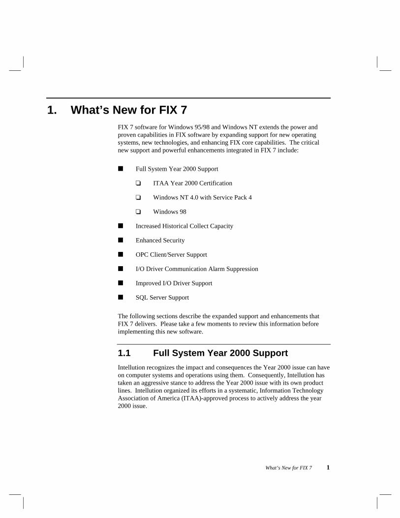
Switching from one SCADA node to the other occurs when the active SCADAnode becomes unavailable. Figure 2-1 shows the relationship between a Viewclient with the automatic failover option enabled and its primary and backupSCADA servers.
14 What’s New for FIX 7
Figure 2-1: Automatic Failover Overview
Automatic Failover on StartupWhen FIX starts up, the View client attempts to establish communication with itsprimary and backup SCADA servers. If both servers are available, the Viewclient establishes a connection with both of them. If only one SCADA server isavailable, the View client establishes a connection with it. If both servers areunavailable, the View client polls both nodes until it establishes a connectionwith at least one of the SCADA servers. The first SCADA server to establish aconnection becomes the active node.

Chapter 2: Features from v6.1.5 15
Once a connection is established, use the following table to determine whathappens when a failover occurs.
When theconnection to theactive SCADAnode is...
And theconnection tothe standbySCADA nodeis...
And the... Then...
Available Available Connection toactive nodebecomesunavailable.
An automaticfailover occurs.
Available Unavailable Connection toactive nodebecomesunavailable.
No failover occurs.
Available Available Connection tostandby nodebecomesunavailable.
No failover occurs.
Unavailable Available Connection tostandby nodebecomesunavailable.
No failover occurs.
Displaying Data During a FailoverIn the situation where you have a picture on a View node that is referencing anactive node, once a connection with the active node is established, the Viewnode starts reading data from that node. When the active node becomesunavailable, the View node loses its session with that node. When the session islost, a message box appears indicating this. Before the View node can switch tothe standby node, the operator must acknowledge the message.
If you want the View node to switch automatically to the standby node withoutoperator intervention, you can suppress the message box by starting the Viewapplication with the command line parameter -s1914. For more information onconfiguring View with this parameter, refer to the View Manual.

16 What’s New for FIX 7
When the View node switches to the standby node, the following events occur:
[1] At-signs (@) are displayed by the links in the open pictures on the Viewnode to indicate the session with the active node has been lost.
[2] The standby node becomes the new active node and the failed nodebecomes the new standby node.
[3] The pictures are resolved automatically using the information from thenew active node. This ensures data integrity.
[4] The at-signs are replaced with process data from the new active node.The node name referenced by these links does not change; it continues todisplay the name of the primary node.
[5] An event message indicating that a failover has occurred is sent to allalarm destinations configured for the View node once process data isreceived from the new active node.
Operator MessagesWhen a backup node is active, the primary node name on operator messagesappears inside brackets. For example, assume the backup node (SCADA2) isactive and the primary node (SCADA1) is not active. If the View client(VIEW1) runs a script that sets SCADA1:AO-1.F_CV to 15, the operatormessage that appears is:
[SCADA1] AO-1.F_CV set to 15 by VIEW1::
The primary node name appears in brackets even though the value that wasmodified is really SCADA2:AO-1.F_CV.
IMPORTANT: In order for data to be displayed on the operator display after afailover occurs, the process databases on both SCADA nodes must be identical.
Collecting Historical Data During a FailoverIf the View node is collecting historical data, it continues to do so after a failoveroccurs. However, the data is collected from the new active node.

Chapter 2: Features from v6.1.5 17
When data is collected from the backup node, the node name referenced by eachhistorical value is replaced with the name of the primary node. Because of thisfeature, make sure to specify the name of the primary node when you create acollection group in Historical Assign. If a failover occurs, the node name isreplaced at runtime.
There may be a gap in the data collected from the time the session with theactive node is lost until the backup node becomes active.
IMPORTANT: In order for data to be collected after a failover occurs, theprocess databases on both SCADA nodes must be identical.
Writing DataData written out to the process goes to the active SCADA node. For example,assume the active node is SCADA1 and the standby node is SCADA2. Beforethe failover, the View node writes data to SCADA1. After the failover, the Viewnode writes data to SCADA2.
Alarm HandlingWhen an alarm occurs on a SCADA server, the alarm is sent to its View client.In general, the View client accepts alarms from the active node; however, if theView client has a session with the standby node, it may receive alarms from thisnode as well.
Any alarms received from the backup node are modified to appear as if theycame from the primary node. When the Alarm Summary link receives thealarms, it appears as if the same alarm has been received twice, once from theprimary node and once from the backup node. Because the link does not displayduplicate alarms, the operator sees only one alarm. This does not mean the otheralarm is lost. Rather, the second alarm replaces the first alarm in the link andsets the alarm’s time stamp.
Other alarm destinations, on the other hand, may contain duplicate alarmsdepending on your alarm routing scheme.
IMPORTANT: In order for the Alarm Summary link to receive the same alarmsfrom both SCADA nodes, the process databases on both nodes must be identical.
When you enable automatic failover on the View node, make sure the AlarmStartup Queue Service is running on both SCADA nodes. This service ensuresno alarm is lost from either SCADA node.

18 What’s New for FIX 7
2.1.2 Configuring a View Node for AutomaticFailover
To configure a View node for automatic failover:
[1] Start the System Configuration Utility (SCU). The SCU window appears.
[2] Select Network from the Configure menu. The Network Configurationdialog box appears.
[3] With the Network check box checked, enter the name of the primarySCADA node you want the View node to communicate with in theRemote Node Name field.
[4] Select the Add button to add the primary node to the Configured RemoteNodes list box.
[5] Select the Configure button. The following text appears:
CAUTION: The remote nodes are automaticallyconfigured. Do not modify these values unlessyou are familiar with the system. Continue?
[6] Select the Yes button. The Remote Node Configuration dialog boxappears.
[7] Enter the name of the backup node in the Backup Node field and press theOK button. If you see the following message:
Session already configured for this node
you have entered a node that is already configured in the Remote Nodeslist. To correct the problem, return to the Network Configuration dialogbox and remove the name of the backup node from the Remote Nodes listbox. Then select the primary node from the list and repeat the previousprocedure starting with step 5.
If the Backup Node field is grayed out, your network protocol is set toNetBIOS instead of TCP/IP. To correct this, refer to the instructions insubsection 2.1.3.

Chapter 2: Features from v6.1.5 19
[8] Press the OK button on the Network Configuration dialog box.
[9] Save this configuration and exit the SCU.
[10] Start FIX.
2.1.3 Changing your Network Protocol to TCP/IP
To change your network protocol:
[1] Go back to your Network Dialog Box.
[2] Select the Advanced button. The following text appears:
CAUTION: The advanced configuration isautomatically determined. Do not modifythese values unless you are familiar with thesystem. Continue?
[3] Press the Yes button. The Advanced Configuration dialog box appears.
[4] Select the TCP/IP protocol from the Installed Protocols list box and pressthe Enable button. The protocol is added to the Enabled Protocols listbox.
[5] Select the NetBIOS protocol from the Enabled Protocols list box andpress the Disable button. The protocol is removed from the EnabledProtocols list box.
[6] Select the OK button to save your changes and return to NetworkConfiguration dialog box.
[7] Select the OK button, save your configuration, and start FIX.

20 What’s New for FIX 7
2.1.4 Adding Links with Question Mark SupportWhen entering a tagname, you have the option of typing in the entire name orpressing the ? button and selecting the node, tag, and field from the Field Selectdialog box. When the latter option is used on a View node with automaticfailover enabled, the name of the primary node always appears in the FieldSelect dialog box, even if the backup node is currently the active node.
For example, assume the primary node is SCADA1 and the backup node isSCADA2. Before the failover, SCADA1 is the active node and its name appearsin the Field Select dialog box. After the failover, SCADA2 becomes the activenode. However, SCADA1 still appears in the Field Select dialog box.
IMPORTANT: The process databases on both SCADA nodes must be identicalin order for the same tags and fields to appear in the Field Select dialog boxafter the failover occurs.
2.1.5 Working with the NSD TagFIX provides a tag called NSD that you can use when designing pictures forautomatic failover. This tag is not a database block. It is a special tag residingon each View node that displays diagnostic and failover information.
Using the NSD tag, you can do any of the following tasks from a View node:
■ Initiate a manual failover.
■ Disable automatic failover temporarily.
■ Trigger an event (such as displaying a message) when automatic failoveroccurs.
■ Show diagnostic failover information.
For more information about completing these tasks, refer to the followingsections.

Chapter 2: Features from v6.1.5 21
Setting up a Sample View NodeTo help explain the features of the NSD tag, the following sections describe asample automatic failover setup on a View node. By duplicating this setup on aView node in your plant, you can understand how to use the NSD tag for yourneeds.
The sample setup configures a View node to establish sessions with SCADA1 asthe primary node and SCADA2 as the backup node. The View node alsocommunicates with SCADA3. Figure 2-2 shows this configuration.
Figure 2-2: Sample View Node Configuration
To set up SCADA1 as the primary node, enter its name in the remote nodes list.Use the procedure in the subsection 2.1.2, Configuring a View Node forAutomatic Failover, to guide you. Figure 2-3 shows the Network Configurationdialog box for a View node with SCADA1 and SCADA3 configured as remotenodes.

22 What’s New for FIX 7
SCADA2 is configured as the backup node by entering its name in the RemoteNode Configuration dialog box, as Figure 2-4 shows. Note that becauseSCADA2 is the backup node, you cannot enter it in the Configured RemoteNodes list.
Figure 2-3: Sample Network Configuration Dialog Box

Chapter 2: Features from v6.1.5 23
Figure 2-4: Sample Remote Node Configuration Dialog Box
After you set up a View node with this configuration, you can reference the NSDfields that monitor SCADA1 (the primary node). When you do this, refer toSCADA1 by its position in the Configured Remote Nodes list. For example,SCADA1 is the second node in the remote nodes list. As a result, to referencethis node with an NSD tag and field, use the following syntax:
Local_nodename:NSD.field_2

24 What’s New for FIX 7
Initiating a Manual FailoverIn addition to automatic failover, you can manually force a failover to occur atany time. Using this feature, you can manually switch to the standby node whenthe active node needs to be shut down for maintenance.
To force a failover manually, write a 1 to the tag and fieldNSD.F_CURACTIVENODE_#. For example, using the nodes shown in Figures2-3 and 2-4, you can manually switch from SCADA1 to SCADA2 by writing a 1to the following tag and field:
Local_nodename:NSD.F_CURACTIVENODE_2
To make the primary node (SCADA1) the active node, write a zero into thisfield.
Disabling Automatic Failover TemporarilyIf you manually force a View node to switch to the standby node and the standbynode is unavailable, the View node automatically switches back to the originalnode you started on. If you need to shut down the original node formaintenance, this feature can be bothersome because you do not want the Viewnode to switch automatically to the node being shut down.
To prevent the View node from automatically switching back, temporarilydisable automatic failover on the View node before you manually force the Viewnode to switch to the standby node. When you disable automatic failover first,the View cannot automatically switch back to the original node if the standbynode is unavailable. However, you can manually switch between the twoSCADA nodes.
To temporarily disable automatic failover on a View node, write a 1 to the tagand field NSD.F_FAILDISABLE_#. For example, using the nodes shown inFigures 2-3 and 2-4, you can disable automatic failover temporarily on the Viewnode by writing a 1 to the following tag and field:
Local_nodename:NSD.F_FAILDISABLE_2
To re-enable automatic failover, write a zero into this field.

Chapter 2: Features from v6.1.5 25
Triggering an Event on FailoverDepending on your process, you may want to trigger an event (such as displayinga message or closing a valve) when a failover occurs. For example, when afailover occurs, you may want to display a message informing the operator of thefailover. Once the operator acknowledges the message, you could automaticallyclose a valve or sound an alarm.
You can trigger an event by examining the value of the tag and fieldNSD.F_FAILOVER_#. This field is set to 1 whenever an automatic or manualfailover occurs. By testing the value of the field with a command languagescript, you can determine if a failover has occurred and then trigger theappropriate action.
For example, using the nodes shown in Figures 2-3 and 2-4, you can display amessage that a failover has occurred using a Commands on Opening scriptsimilar to the following:
DECLARE #FAILOVER STRING GLOBALDECLARE #CURVAL NUMERIC GLOBAL#FAILOVER = “”STRCAT #FAILOVER #GS_NODESTRCAT #FAILOVER “:NSD.F_FAILOVER_2”GETVAL #FAILOVER #CURVALIF #CURVAL == 1NOTE “A failover has occurred”SETVAL #FAILOVER 0ENDIFPAUSE 20GOTO 6
Notice at the end of the script (line 9), the value of the F_FAILOVER field isreset to 0. This is necessary because once the F_FAILOVER field is set to 1,FIX assumes a failover has occurred and does not report another failover untilyou reset the field to 0. For this reason, the script resets the field after all theappropriate actions have been triggered.

26 What’s New for FIX 7
Displaying Diagnostic DataThe remaining NSD fields are read-only and let you display diagnosticinformation for a View node. This information is useful to monitor sessions onyour network, determine which nodes are active, and display the name of thelocal node. In the event that a SCADA node becomes unavailable, these fieldscan also display an error code and text describing the current state of theconnection with each SCADA node. Table 2-1 describes the fields you can useto display diagnostic information.
Table 2-1: Diagnostic NSD Fields
The tag and field... Displays...
NSD.A_ACONNREASON_# Text describing the current state of the connection tothe active node.
NSD.A_PRIMARYSCADA_# The name of the primary SCADA node.
NSD.A_BACKUPSCADA_# The name of the backup SCADA node.
NSD.A_ACTIVESCADA_# The name of the active SCADA node.
NSD.A_ACTIVESTATUS_#
(Also supports F_ format)
The status of the connection to the active node.
Possible values:
■ OK
■ An error code
For the exact meaning of the error codes, refer toTable 2-3.
NSD.A_PRIMARYSTATUS_#
(Also supports F_ format)
The status of the connection to the primary node.
Possible values:
■ OK
■ An error code
For the exact meaning of the error codes, refer toTable 2-3.

Chapter 2: Features from v6.1.5 27
Table 2-1: Diagnostic NSD Fields (continued)
The tag and field... Displays...
NSD.A_BACKUPSTATUS_#
(Also supports F_ format)
The status of the connection to the backup node.
Possible values:
■ OK
■ An error code
For the exact meaning of the error codes, refer toTable 2-3.
NSD.A_CONNDIRECTION The direction of the failover. The system displays <for incoming and > for outgoing signals.
NSD.A_PCONNREASON_# Text describing the current state of the connection tothe primary node.
NSD.A_BCONNREASON_# Text describing the current state of the connection tothe backup node.
NSD.A_LOCALNAME The name of the local node.
NSD.F_FAILOVERMANL_# The number of manual failovers this connection hashad.
NSD.F_FAILOVERTOTAL_# The total number of failovers, both manual andautomatic, this connection has had.

28 What’s New for FIX 7
The following fields allow you direct control over the automatic failover option.Additional information on these fields can be found in the specified sections.
Table 2-2: Automatic Failover Control Fields
The tag and field... Lets you...
NSD.F_CURACTIVENODE_# Write a 1 to this field to switch the primaryconnection to the backup, and writing a 0 switchescommunications from the backup node to the primarynode. Refer to the subsection Initiating a ManualFailover for more detailed instructions on using thisfield.
NSD.F_FAILDISABLE_# Temporarily disable the automatic failover option bywriting a 1 to this field and re-enabling it by writing a0. Refer to the subsection Disabling AutomaticFailover Temporarily for more detailed instructionson using this field.
NSD.F_FAILOVER_# Trigger an event by examining the value of the tagand field NSD.F_FAILOVER_#. This field is set to 1whenever an automatic or manual failover occurs. Bytesting the value of the field with a commandlanguage script, you can determine if a failover hasoccurred and then trigger the appropriate action.Refer to the subsection Triggering an Event onFailover for more detailed instructions on scripting.
Table 2-3: Runtime Network Errors
Error Code Description
1605160816101624
Command timed out.Invalid Local Session Number.Session Closed.Session Ended Abnormally.
These errors occur when the remote node is down. When the remotenode is brought back up, the Connection Manager re-establishes thesession.

Chapter 2: Features from v6.1.5 29
Table 2-3: Runtime Network Errors (continued)
Error Code Description
1620 No answer, can’t find remote node
The session cannot be established because either a remote node is notoperating, a cabling problem exists between the nodes, or the remotenode name is not registered on the network.
Verify both nodes are running compatible TCP/IP network software.Refer to the FIX Network Manual for more information.
1914 Connection NOT established with node.
The Connection Manager has not yet established a connection with theremote node.
Wait for the Connection Manager to establish the session.
1960 FIX dynamic connection in progress.
The Connection Manager is in the process of establishing a dynamicconnection with the remote node.
Wait for the Connection Manager to establish the session.
1964 FIX has been shut down on remote node.
The Connection Manager detected that FIX has been shut down on theremote node. This error code shows up temporarily and then changes to1914.
8517 Node not found in TCP hosts database.
The node name that you are trying to connect to cannot be resolved to anIP address. The name is probably not in the local HOSTS file or on theWINS server.
Obtain the remote node’s IP address and add it to the HOSTS file. Referto the FIX Network Manual for more information.

30 What’s New for FIX 7
In addition to providing the fields in Table 2-1, Intellution supplies diagnosticdisplays you can use with FIX. These displays are pre-built pictures with linksthat reference the diagnostic NSD fields. By using these displays, you canquickly display diagnostic information for any View node.
Intellution supplies the following displays:
NSD.ODF — a network status display showing the local node name, eachincoming connection, each outgoing connection, and each connection’sstatus. This display always shows the primary node name even if thebackup node is the active node.
NSDREDUN.ODF — a network status display showing the information inNSD.ODF plus the names of the active node, the primary node, and thebackup node.
The following table explains the buttons on the NSDREDUN.ODF display.
Clicking... Lets you...
Primary Switch communications from the primary node tothe backup node.
Backup Switch communications from the backup node tothe primary node.
Enable Enable the system to perform an automaticfailover.
Disable Disable the system from performing an automaticfailover.
Reset Clear the flags caused by an automatic or manualfailover.
These displays are provided in the Picture path of your View node. You need tomodify these pictures to reference your local node name.
Chapter 2: Features from v6.1.5 31
To do this, follow these instructions:
[1] Open the picture in Draw.
[2] Select the Select All option.
[3] Select the Search and Replace option.
[4] Enter the following:
*:*
local_nodename:*
[5] Save the picture.
2.2 Remote Historical DisplayRemote Historical Display allows you to display historical data that is collectedand stored on another computer. Before attempting to implement the advanceddata retrieval strategy discussed in this section, make sure you have a goodunderstanding of Historical Display charts. Refer to the Historical TrendingManual for more information on historical display charts.
2.2.1 Why Use Remote Historical Display?
One reason you might use Remote Historical Display is if your SCADA strategycalls for you to store historical data files in two or more different directories.Remote Historical Display allows you to create charts with historical data fromone or more directory paths in addition to the default FIX Historical Data path.
Also, you may want to use Remote Historical Display to store all of yourhistorical collection files on one computer on your network, and to display chartsof this data on a different node. Previously, Historical Display charts could onlydisplay data that was stored in the FIX Historical Data path, as defined in theSystem Configuration Utility.

32 What’s New for FIX 7
2.2.2 Using Remote Historical Display
This section explains the necessary steps for displaying remote data in ahistorical chart. Refer to the online help for more information on specific dialogbox fields.
NOTE: In the course of testing, it was found that there may be a delay indisplaying or updating a chart when one or more of the pens is attempting toaccess a remote node to which a network connection or file sharing is notavailable. The delay is caused by the Microsoft Network time-out and retrylogic. Due to this, Intellution recommends that 1 Minute Auto Update not beused with Remote Historical Display.
Defining a Remote Historical Data PathTo define a remote historical data path:
[1] In Historical Display, select the Define Remote Paths command from theUtilities menu. The Define Remote Historical Data Paths dialog box,shown in Figure 2-5, appears.
Figure 2-5: Define Remote Historical Data Paths Dialog Box

Chapter 2: Features from v6.1.5 33
[2] Enter a name in the Remote Data Path Alias field. The name you enterdoes not necessarily have to be a remote FIX node name; it only needs tobe a unique name that follows the standard FIX node naming convention.For example, if you want to define a local historical data path in additionto a default historical data path, you can enter a name such asHTRDATA2.
[3] Enter the historical data subdirectory path in the Historical Data Pathfield. The path can be a drive letter path (C:\FIX32\MYDATA, forexample) or a Universal Naming Convention (UNC) path(\\COMP2\FIX32\MYDATA, for example).
Do not enter the actual subdirectory where the data is stored. Forexample, the following would be a correct path: C:\FIX32\HTRDATA.The following would be an incorrect path: C:\FIX32\HTRDATA\NODE1
[4] Click Add. The name and path appear in the list box.
[5] Click OK to save your changes and close the dialog box.
Modifying a Remote Historical Data PathTo modify a remote historical data path:
[1] Select a previously-defined name and path from the list box. The nameand path fields automatically display the name and path for that historicaldisplay path definition.
[2] Edit the name and path in their respective fields as desired.
[3] Click Modify. The data in the list box updates with the most recentinformation.
[4] Click OK to save your changes and close the dialog box.

34 What’s New for FIX 7
Deleting a Remote Historical Data PathTo delete a remote historical data path:
[1] Select a previously-defined name and path from the list box.
[2] Click Delete. When asked to confirm the deletion, click Yes and the datain the list box is deleted.
[3] Click OK to save your changes and close the dialog box.
2.2.3 Using Remote Historical Paths in PenDefinitions
Defining a remote historical path is the first step in displaying remote historicaldata. However, to display the data, you must define a historical data pen foreach tagname you want to trend. See the Historical Trending Manual for moreinformation on creating a pen. This section assumes familiarity with thisprocess.
The Add Pen Group dialog box shows the tagnames selected for trending thatare displayed in the chart. When you select a pen from the Pens list box, theattributes for the pen appear in the Pen Definitions area, shown in Figure 2-6.

Chapter 2: Features from v6.1.5 35
Figure 2-6: Pen Definitions Area
Defining a Remote Historical Data PenTo define a remote historical data pen:
[1] Select the Define Pen Groups command from the Utilities menu.
[2] Click Add.
[3] Click the Historical radio button.

36 What’s New for FIX 7
[4] Enter the Remote Data Path Alias and tagname you want to trend in theTagname field. Use the following syntax:
ALIAS::NODE:TAG.FIELD
where ALIAS is the name you defined in the Remote Data Path Alias fieldand NODE:TAG.FIELD is the tagname you want to use for the pen.
[5] Enter collection and display information for the tagname in the PenDefinitions area. See the Historical Trending Manual for moreinformation.
[6] Click Add. The new tagname is added to the Pens list box.
[7] Enter a group name in the Pen Group field. Click Save to save your newpen group and click OK to close the Define Pen Groups dialog box.
NOTE: If you define a path for the local node name (the node where HistoricalDisplay is running), the path overrides the HTRDATA path defined in the SCU.Also, if the ALIAS portion of the remote pen syntax is omitted from the Penconfiguration, FIX uses the local node name as the ALIAS. For example, ifHistorical Display is running on SCADA1, and you have a pen configured asSCADA1::NODE:TAG.FIELD and another pen configured asNODE:TAG.FIELD, the data retrieved is the same.
2.2.4 Remote Historical Example
Let’s say that you have created a historical display chart on your local computer,COMP1, and your FIX node name is MYNODE. One of the pens in this chart isconfigured to trend the tagname MYNODE:AI1.F_CV, which has been collectedand stored in the historical data path you defined in the SCU.
Now you want to create a second pen for this chart. However, the data that youwant to use for this pen is stored on another computer in your network, COMP2,and that computer’s FIX node name is YOURNODE. To display this data, youneed to find out the path of the historical data files on COMP2. For the purposesof this example, let’s say they are stored in the \HTRFILES\SAVE path.

Chapter 2: Features from v6.1.5 37
First, you need to define the remote historical path on your node by entering aalias and path in the Define Remote Historical Data Paths dialog box. Let’s sayyou enter HISTSRV as the alias and \\COMP2\HTRFILES\SAVE as the path.Next, you need to define a pen that will trend data from the remote computer,COMP2. In the Pen Definitions area of the Pen Configuration dialog box, youenter the tagname as HISTSRV::YOURNODE:AI1.F_CV. Historical Displaywill now retrieve data from the remote directory\\COMP2\HTRFILES\SAVE\YOURNODE for the second pen.
NOTE: If you are upgrading from a 16-bit Remote FIX system, you need todefine a path for each Remote Data Node in your pen groups before displayingthe remote data. Each path must specify where the remote node’s historicaldata is stored.
2.3 Tiling and Cascading Pictures in ViewWhen using FIX, View is your tool to open displays and show them to operators.View lets you open up to 15 pictures at one time. Depending on the type, size,and position of the pictures opened, this can result in one or more pictures buriedbeneath the picture that is on top. One way to correct this situation is tomanually move and resize the standard pictures. However, this can be a tediousand time-consuming process. A faster, easier way to arrange the open standardpictures in View is to use the Tile and Cascade commands.
The Tile command arranges the open standard pictures so that no pictureoverlaps any other picture and resizes the pictures, as shown in Figure 2-7.Pictures are tiled in the last order they were selected.

38 What’s New for FIX 7
Figure 2-7: Tiling Pictures
NOTE: The Tile command does not affect titleless standard pictures, pop-uppictures, or standard pictures that cannot be resized. A subpicture moves withthe standard picture that opened it and may be clipped when the window isresized.
The Cascade command staggers the open standard pictures so that each picturecan be selected by its title bar, as shown in Figure 2-8. The standard pictures arenot resized in any way. Notice that each picture is staggered slightly to the rightand each title bar is completely visible. Pictures are cascaded in the last orderthey were selected.

Chapter 2: Features from v6.1.5 39
Figure 2-8: Cascading Pictures
NOTE: The Cascade command does not affect titleless standard pictures orpop-up pictures. A subpicture moves with the standard picture that opened itand may be clipped by the edge of the screen.
2.3.1 Providing Access to the Tile and CascadeCommands
Like all menu commands in View, you can enable or disable the Tile andCascade commands from a command language script.
To enable the commands, use the following commands:
MENU TILE TRUEMENU CASCADE TRUE

40 What’s New for FIX 7
To disable (gray out) the commands, use the following commands:
MENU TILE FALSEMENU CASCADE FALSE
2.4 Multiple Picture Search and ReplaceSupport
FIX allows you to search and replace a specified Node:Tag pattern withinmultiple pictures. This section describes how to use the new Multiple PictureSearch and Replace function in Draw to accomplish this.
IMPORTANT: This Multiple Picture Search and Replace function onlymodifies the Node:Tag references in pictures, and does not change anyreferences in tag group (TGE) or key macro (KMX) files that may be associatedwith these pictures. You may need to modify your TGE and KMX files as wellwhen replacing Node:Tag combinations.
2.4.1 Searching and Replacing Tagnames in MultiplePictures
Links and dynamic properties work with data from valid database tags. At times,you may want to change the tagnames specified in link and dynamic propertydialog boxes from one node to another node. The Multiple Picture Search andReplace command lets you automate this type of change within multiple pictures.
Tagnames throughout FIX have the following format:
NODE:TAG.FIELD
Multiple Picture Search and Replace identifies and replaces all pictures for theNODE and TAG portions of the tagname. Multiple Picture Search and Replacedoes not modify the FIELD portion of the tagname.
When Multiple Picture Search and Replace encounters a matching tagname in agroup that uses the Group Tagname function, it changes the tagname in theGroup Tagname field and in all the tagname fields in that group.

Chapter 2: Features from v6.1.5 41
Using Multiple Picture Search and ReplaceIMPORTANT: Using the Multiple Picture Search and Replace commandmakes changes immediately. You cannot cancel or undo a search-and-replaceaction after Draw executes it.
To use Multiple Picture Search and Replace:
[1] Select the Multiple Picture Search and Replace command from the Filemenu.
The Multiple Picture Search and Replace Tagnames dialog box appears,as shown in Figure 2-9.
Figure 2-9: Multiple Picture Search and Replace Tagnames Dialog Box
[2] Click the Set Paths button to set the path to the ODF picture files youwant to include in the search and replace operation

42 What’s New for FIX 7
[3] Select the pictures you want to search through from those in the list box.The Node:Tag search pattern you specify only applies to the pictures youselect. Click the Select All button to select all the pictures. Holdingdown the <Ctrl> key allows you to select specific pictures from within thelist.
[4] In the Search For Field, type the node and tag pattern that you are lookingfor using the following format:
NODE:TAG
[5] Using the same format, type the replacement node and tag pattern in theReplace With field. Figure 2-10 shows a number of pictures selectedalong with the search and replace patterns entered.
Figure 2-10: Example of a Multiple Picture Search and Replace

Chapter 2: Features from v6.1.5 43
[6] Select Replace. Draw replaces every occurrence of the node and tagcombination in each object in every selected picture. If you want to leavethe dialog box without replacing any tagnames, select Done instead ofReplace.
[7] Select Done to exit.
Using Multiple Picture Search and Replace with the Asterisk WildcardThe Multiple Picture Search and Replace command supports the asterisk (*)wildcard in both the Search For and Replace With fields. Table 2-4 describeseach use of the asterisk wildcard.
Table 2-4: Using Multiple Picture Search and Replace Wildcards
Field Wildcard Meaning
Search For *:* Search for all tags.
Search For N*:* Search for all tags with a node name that beginswith N.
Search For NODE*:* Search for all tags with a node name that beginswith the first four characters NODE.
Search For *:TAG Search for all tags with TAG as the tag name.
Search For NODE:* Search for all tags with NODE as the node name.
Replace With *:TAG Replace the search tag with TAG, but leave thenode as is.
Replace With N*:* Replace the first character of the search node withN, and leave the tag as is.
Replace With NODE*:* Replace the first four characters of the searchnode with NODE, and leave the tag as is.
Replace With NODE:* Replace the search node with NODE, and leavethe tag as is.
Replace With NODE:TAG Replace the search node with NODE and thesearch tag with TAG.

44 What’s New for FIX 7
Table 2-5 gives examples of using the asterisk wildcard.
Table 2-5: Multiple Picture Search and Replace Wildcard Examples
OriginalTagname Search For… Replace With…
ModifiedTagname
NODE1:AI1 N*:A* M*:B* MODE1:BI1
NODE1:AI1 *1:*1 *2:*2 NODE2:AI2
NODE1:AI1 *:* TOOMANYCHAR:* NO CHANGE
NODE1:AI1 *:AI1 NEWNODE:A NEWNODE:A
NODE1:AI1 *:* N2:A2 N2:A2
NODE1:AI2 *1:*2 *3:*4 NODE3:AI4
NODE1:AI2 NOD*:AI* BE*:CO* BEE1:CO2
2.5 Historical Tag Assign CSV File Importand Export
FIX allows you to export Historical Tag Assign (HTA) files so you can:
■ Export collection group files so you can import these files into anotherapplication, such as Microsoft Excel to make modifications.
■ Transfer collection group files from one node to another.
■ Export collection group files so you can document your system.
■ Import CSV files modified in applications such as Microsoft Excel.

Chapter 2: Features from v6.1.5 45
2.5.1 Exporting a Collection Group File
HTA allows you to export the contents of a historical group file to CSV format.To do this, follow these steps:
[1] While in HTA, select Save As from the File menu.
[2] Enter a file name and click Save.
Your file is saved to your Historical path with a .CSV file extension.
If you are only transferring group files from one node to another, you do nothave to open the CSV file.
2.5.2 Editing a CSV File
With the contents of your collection group file in CSV format, you can open thefile using an application such as Excel to print out your group file’s contents fordocumentation purposes, or you may have a need to change the contents of thefile.
CSV File FormatBefore you modify the contents of a CSV file, you must understand the format ofthe file. Figure 2-11 shows the file format for an HTA CSV file in MicrosoftExcel.

46 What’s New for FIX 7
Figure 2-11: Sample CSV File in Microsoft Excel

Chapter 2: Features from v6.1.5 47
Table 2-6 describes the contents of the sample file in Figure 2-11.
Table 2-6: Sample CSV File
These Rows… Contain This Information…
1 through 4 Header data for the file. The header dataincludes the title, file name and path of theCSV file, and the time the file was exported.
5 through 7 Settings for the collection group. In thissample, the collection length is set to 8 hours.Data will be purged automatically every 5days.
8 through 11 Specifications for each collection group. Inthis sample, tags are being collected from threegroups.
13 through 20 The tagnames and deadband rate for eachcollection group.
Tags and their associated deadband rates aredisplayed horizontally, from left to right. Asmany as five tags will appear on each row foreach collection group. If more than five tagsare defined in a group, additional rows arecreated to display the tags.

48 What’s New for FIX 7
Modifying a CSV FileTo modify the contents of a CSV file:
[1] Export an existing group file into CSV format. See subsection 2.5.1 forinstructions on exporting a file.
[2] Open the file in an application that supports comma separated formatting,such as Excel.
NOTE: You can use a text editor to edit the file. However, it isrecommended that you use a spreadsheet program, such as Excel.
[3] Carefully edit the file as necessary. Make sure that you do not change theformatting of the file. Refer to Table 2-6 for a description of each sectionof the file.
[4] Save the modified file. Be sure that the file extension is .CSV.
You can now import the file into Historical Trend Assign.
2.5.3 Importing a CSV File into Historical TrendAssign
To import a CSV file into the Historical Trend Assign (HTA) program, do thefollowing:
[1] Start HTA.
[2] Select Open from the File menu.
[3] Select the CSV file you want to import and click Open. HTA imports theselected file.
If errors are encountered during the import, an error message will appear. Errorsare logged to an HTAIMP.ERR file. This file is stored in the Historical path,which is typically C:\FIX32\HTR.

Chapter 2: Features from v6.1.5 49
2.6 Background ScriptsFIX includes the ability to run a background script in View. As long as you haveView running, your background script will run, regardless if a picture is open ornot. You can also add View to the startup task list to automatically start yourscript when FIX starts.
To incorporate a background script in your View application, follow these steps:
[1] Open the Macro Editor and open the VIEW.KMX file.
[2] In the Function Key field, enter AUTO.
[3] In the Commands field enter the script you want to run.
[4] Save your VIEW.KMX file.
The next time you run View this script will automatically run.
Keep in mind that if you want the script to run continuously, you must loopwithin the script. Otherwise, the script will simply run to completion and stop.

50 What’s New for FIX 7

Chapter 3: Features from FIX 6.1 51
3. Features from FIX 6.1FIX v6.1 extended the power of FIX software by providing the following:
■ Improvements to Draw/View, including:
❏ A new Command Language Editor
❏ AutoCAD file import.
❏ Right Mouse Button support.
❏ New Picture Types functionality.
❏ The ability to save color threshold and grid settings.
❏ RESOLVEVARS command.
■ Alarm Summary enhancements, including:
❏ “New alarm” color.
❏ Manual alarm deletion.
❏ Filter by node:tag with wildcards.
❏ Date In and Date Last columns.
❏ Alarm Startup Queue synchronization.
■ A configurable Alarm File delete period.
■ Remote Alarm filtering.
■ New FIX Startup command line parameter.
■ Save and restore automatic update rates in Historical Trending.
■ Database block selection by full name.
■ Electronic Documentation.

52 What’s New for FIX 7
The sections in this chapter describes the features listed above.
NOTE: These features were new for v6.1 and are still present in FIX 7.
3.1 New Command Language EditorThe Command Language Editor has been redesigned. A new user interface andseveral new features have been added to simplify the building of commandlanguage scripts.
3.1.1 New Interface Design
The most visible difference in the Command Language Editor is the editingwindow. This new design replaces the six edit fields that existed in earlierversions of the editor.
To use the new editor, type a script in the same way you would type a documentin Notepad. The editor retains the case of the items you enter, as well as theformatting (spaces and tabs).
The editing window itself is both movable and sizable. The size and the positionthat you set is stored and is recalled at the next editing session. However, onceyou exit and restart Draw, the editor returns to its default size and position.

Chapter 3: Features from FIX 6.1 53
Figure 3-1: Command Language Editor
The new design features of the editor, as well as the functionality provided, aredetailed in the following subsections. Users of earlier versions of the CommandLanguage Editor may want to pay particular attention to subsection 3.1.5,Importing Existing Command Language Scripts .
3.1.2 Command Buttons
At the top of the editor is a row of command buttons, as shown in Figure 3-2.These buttons provide quick access to the most frequently used commands. Tooltips are enabled with the buttons to easily identify their functionality.
Figure 3-2: Command Buttons Bar

54 What’s New for FIX 7
A description of each of the command buttons is provided below.
Cut — removes the highlighted text and copies it to the global clipboard.
Copy — copies the highlighted text to the global clipboard without removing thehighlighted text.
Paste — copies the text from the global clipboard into the edit field. If any textis highlighted, that text is replaced. If no text is highlighted, the new textis inserted at the cursor position.
Undo — reverses the last operation only within the edit field. This operationonly implements one level of undo and redo. The Undo button is onlyenabled if an Undo operation is possible.
Search and Replace — opens the Search and Replace dialog box.
The Search and Replace function is discussed in greater detail in subsection3.1.3, Search and Replace.
SQL — opens the SQL Command Configurator dialog box, as shown below.This button is only enabled if the cursor is on a line that starts with #var=.
For additional information on the SQL Command Configurator dialog boxand on building SQL commands, see the Command Language manual.

Chapter 3: Features from FIX 6.1 55
When you click OK and exit the SQL Command Configurator dialog box,the SQL command text replaces all the text on the current line.
Import — invokes the Import function, which is facilitated through a standardOpen File dialog box. You can then import any ASCII file created in astandard text editor. The default directory is the FIX Picture path, and thedefault extension is .TXT.
Export — invokes the Export function, which is facilitated through a standardFile Save dialog box. The default directory is the FIX Picture path, andthe default extension is .TXT.
Errors — opens the Command Script Errors dialog box.
When you click OK in the new Command Language Editor, any and allerrors are collected, placed into a list, and displayed in the CommandScript Errors dialog box, as shown in Figure 3-3. Both the text of theerror and the line number appear in the dialog box.
NOTE: While working in the editor, if there are any outstanding errors,the button is enabled. If there are no outstanding errors, the button isdisabled.
Figure 3-3: Command Script Errors Dialog Box

56 What’s New for FIX 7
You can work in both the script and the error list dialog simultaneously.For example:
If you... Then...
Select an error in theCommand Script Errorsdialog box and click OK
The cursor is placed at thebeginning of the appropriateline in the script and theCommand Script Errorsdialog box closes.
Select an error in theCommand Script Errorsdialog box and double-click it
The cursor is placed at thebeginning of the appropriateline in the script and thefocus is returned to theCommand Language Editor.However, the CommandScript Editor remains open.
Insert Tag — opens the standard Field Select dialog box, shown in Figure 3-4.If you complete the fields and click OK, a node:tag.field string is pastedinto the script. Any highlighted text is replaced. If there is no texthighlighted, the string is inserted at the cursor position.
Figure 3-4: Field Select Dialog Box

Chapter 3: Features from FIX 6.1 57
For more information on the Field Select dialog box, see the Workingwith Tagnames section of the Basics manual.
Quick Commands — opens the Available Commands dialog box, shown inFigure 3-5. This dialog box contains an alphabetical list of all the validcommands and their proper syntax. You can select a command byhighlighting it, and then paste it into a script by clicking the Paste button.Any text that is highlighted is replaced. If there is no text highlighted, thecommand is inserted at the cursor position.
Figure 3-5: List Commands Dialog Box
Goto button — displays the line number that the cursor is on.
If you click the left mouse button while the cursor is over the label or theline number itself, the Goto dialog box appears. Enter either a linenumber or a label to move the cursor and click OK. The cursor is thenplaced on that line.
If the line number entered is greater than the number of lines in the script,the cursor is placed on the last line. If you enter a label that does notexist, an error is displayed and the cursor does not move.

58 What’s New for FIX 7
3.1.3 Search and Replace
The Search and Replace function is invoked by either clicking the Search andReplace button or by selecting the command from the right mouse button menu.Once the function is called, the Search and Replace dialog box, shown in Figure3-6, appears.
Figure 3-6: Search and Replace Dialog Box
When the dialog box opens, the fields will reflect one of the two followingconditions:
If... Then...
You have any text highlightedwhen you call the Search andReplace function
That text is placed in the Searchfor text field.
You do not have any texthighlighted when you call theSearch and Replace function
The Search for, Replace with,Case Sensitive and WrapAround fields reflect the lastSearch and Replace actionperformed in this session ofDraw.

Chapter 3: Features from FIX 6.1 59
Once the dialog box is open, follow these steps to complete the desired Searchand Replace operation:
[1] Enter the text you want to search for (up to 100 characters) in the Searchfor field.
[2] Enter the text you want to substitute (up to 100 characters) in the Replacewith field.
[3] Check the Case Sensitive box if you want your search to be case sensitive.
[4] Click the Search Next button. A forward search is started directly afterthe cursor or after the highlighted portion of the script.
or
Click the Search Previous button. A backward search is started directlybefore the cursor or before the highlighted portion of the script.
If text is found, it is highlighted. If not, a message is displayed indicatingthat the text was not found. You may press either button again to re-startyour search.
IMPORTANT: Check the Wrap Around check box to enable the SearchNext, Replace All and Search Previous operations to wrap to the start (orthe end) of the script when performing these functions.
[5] Click the Replace button to replace the currently highlighted text with thetext in the Replace with field.
or
Click the Replace All button. This allows the entire script to be searched,and all matches are replaced with the text in the Replace with field. Oncethe operation is complete, a message is displayed showing how manyreplacements were performed.
The Replace All function only searches in a forward direction.
[6] Click Exit to leave the Search and Replace dialog box and return to theCommand Language Editor.

60 What’s New for FIX 7
3.1.4 Right Mouse Button Commands within theCommand Editor Environment
You can access a menu of commands by right-clicking anywhere within the editwindow of the new Command Language editor. The following commands areavailable:
Cut
Copy
Paste
Search/Replace...
Goto...
Help
Quick Commands
Insert Tag...
Once the menu is open, there are two ways to use it:
■ Navigate through the selections by using the cursor keys. Highlight thecommand you want to activate and press <Enter>.
■ Move the mouse to highlight the command you want to activate, and thenclick either the right or left mouse button.

Chapter 3: Features from FIX 6.1 61
Context Sensitive HelpMany of the commands accessible through the right mouse button menu are thesame as the commands available from the Command Button bar. The exceptionis the Help command.
If you... Then...
Press the Help button on theCommand Language Editor
Help for Command LanguageEditor opens.
Access the Help command fromthe right mouse button menuand the cursor is positioned on avalid command word
Help for the selected commandopens.
NOTE: If the cursor is not positioned over a valid command, Help will beunavailable from the right mouse button menu.
3.1.5 Importing Existing Command LanguageScripts
The multi-line edit window design of the new Command Language Editor haseliminated the line numbers found in earlier versions of the editor.
When the new editor reads in an older script, all GOTO Line# commands arereplaced by GOTO Label commands and labels, represented by ampersands (&),are inserted into the script. Also, NULL statements will be replaced with asemicolon (;).
The following example shows both an original script and then the same scriptafter being read into the new Command Language Editor.
Original script New Command Script
1 IF #VAR1>5 IF #VAR1>52 GOTO 5 GOTO L53 ENDIF ENDIF4 NULL ;5 #VAR1 = 0 &L5
#VAR1 = 0

62 What’s New for FIX 7
3.2 .DXF Picture Import.DXF picture import is now available as an option in FIX Draw. In earlierversions of FIX, AutoCAD pictures had to be re-created in the FIX Drawenvironment, or they were imported as static bitmaps. Now, using the .DXFImport functionality, you can assign dynamic properties to these objects.
The .DXF Import feature allows you to import AutoCAD pictures into FIX anduse them as .ODF files. The new picture Import Wizard, discussed in thefollowing section, guides you through the process of importing a .DXF file into afull screen .ODF file, which will reside in the current FIX Picture path.
NOTE: This option must be purchased from Intellution separately, as part ofthe FIX Integration Toolkit.
AutoCAD Objects vs FIX ObjectsObjects imported into FIX will not appear in their identical AutoCAD pixellocation. Instead, the objects will be in the same proportions and will be locatedin the same positions relative to the other objects in the file. The objects youimport into FIX will also maintain the colors they were assigned in AutoCAD.
In order to assign dynamic properties to the imported objects, each AutoCADentity must be represented by one or more FIX objects. However, noassumptions are made about the AutoCAD entities. For example, an AutoCADobject drawn as a polyline will not be assumed to be a polygon, which can befilled. It is only imported as a polyline.
LayersOnly objects in visible layers are imported. Objects are not separated based onthe layers in which they were created and are not grouped by layer.
Table 3-1 describes the FIX object created by the import of specific AutoCADobjects.

Chapter 3: Features from FIX 6.1 63
Table 3-1: AutoCAD Objects in FIX
These AutoCAD objects... Appear as the following FIXDraw objects...
Arcs Polylines
Boundary Hatches One or more disjointedpolylines
Ellipses Grouped, multiple polylines
Rectangle 5-point polyline
Oval Hollow, oval object
Text Text object
Solids Polygon
Polylines with QuadraticCurve
Polyline
Polylines with curve fit One or more polylines groupedas one object
Polyline with filet Polylines
Closed polygon Polyline
Blocks A group of objects
Two polylines with achamfer
Grouped polylines
Double lines A group of polylines
Donuts Polylines grouped as oneobject
Points Not imported

64 What’s New for FIX 7
3.2.1 Using the Import Wizard
You can now import graphics files into FIX Draw using an Import Wizard. Thisreplaces the Import PCX and Import ADF commands previously available fromthe File menu in Draw. A button for the Import Wizard is now included in thelist of available buttons and may be added to the toolbox, as well.
To import either a .DXF, .PCX or .ADF graphic file into Draw:
[1] Select the Import Wizard, as a menu item or as a toolbox button. TheWelcome dialog box appears, as shown in Figure 3-7.
Figure 3-7: The Import Wizard Welcome Dialog Box
[2] Select the type of file you want to import by clicking the appropriateoption (DXF, PCX, or ADF).
[3] Click the Next button. The Files to Import dialog box appears, as shownin Figure 3-8.

Chapter 3: Features from FIX 6.1 65
Figure 3-8: Files to Import Dialog Box
[4] Enter the name of the file(s) to import, either manually or by using theBrowse button.
When importing more than one .DXF or .ADF file:
If... Then...
You do not select theBatch-Mode Import box
By default, the wizardimports all files into one.ODF file.
You select the Batch-Mode Import box
The wizard imports each.DXF or .ADF file into itsown .ODF file.
[5] If you are importing .ADF or .PCX files, click the Finish button.
If you are importing .DXF files, continue to the Font Mapping dialog box,shown in Figure 3-9.

66 What’s New for FIX 7
Figure 3-9: Font Mapping Dialog Box
[6] From this dialog box, select the font and the font style to represent yourAutoCAD font.
Select the Import Non-Horizontal Text box if you want to have any non-horizontal text currently present in your AutoCAD file imported into yournew .ODF file.
If you select the check box, the text is imported and placed into the new.ODF in the same location as the AutoCAD’s text origin, but it will behorizontally oriented.
If the box is cleared, then the non-horizontal text is not imported.
[7] Click the Finish button.

Chapter 3: Features from FIX 6.1 67
3.3 Using the Right-Mouse ButtonAs an alternative to using the standard pull-down menus to access a command,FIX Draw and View systems support a pop-up menu that appears when youright-click the mouse. This menu provides a shortcut to some of the commandsavailable on the pull-down menus.
The pop-up menu is available both with and without any objects selected.However, the menu items that appear vary based on whether an object isselected, as well as what type of object is selected.
ExampleIf an object is selected in Draw and you right-click the mouse, the item CreateDynamo appears. If, however, a Dynamo is selected in Draw, then the CreateDynamo menu item does not appear, but the Convert to Objects item is listed inthe menu.
3.4 Picture TypesThe displays you create with Draw are called pictures. Draw distinguishesamong the following types of pictures:
■ Standard pictures
■ Subpictures
■ Pop-up pictures
Picture DefinitionsA standard picture is most commonly used for your full screen displays.Standard pictures can open other pictures inside them. The pictures that appearinside of a standard picture are called subpictures. Subpictures can be eithertitled or untitled, and are best suited for showing detailed information about anitem in a standard picture. Subpictures can also appear inside other subpictures.This feature makes subpictures a good choice when you want to show severallevels of detail.

68 What’s New for FIX 7
Figure 3-10 shows an example of a standard picture and a subpicture. Foradditional information about standard and subpictures, refer to subsection 3.4.1,Working with Standard Pictures and Subpictures .
Figure 3-10: Sample Standard Pictures and Subpictures
A pop-up picture is a picture that is always in front of all currently open pictures.For this reason, pop-up pictures are well suited to show alarm messages, controlpanels, toolbars, or menus. Pop-up pictures are also ideal for simulating dialogboxes that appear off your standard pictures.
Pop-up pictures can be moved anywhere on the screen. Moving a pop-up picturedoes not affect any other open window.
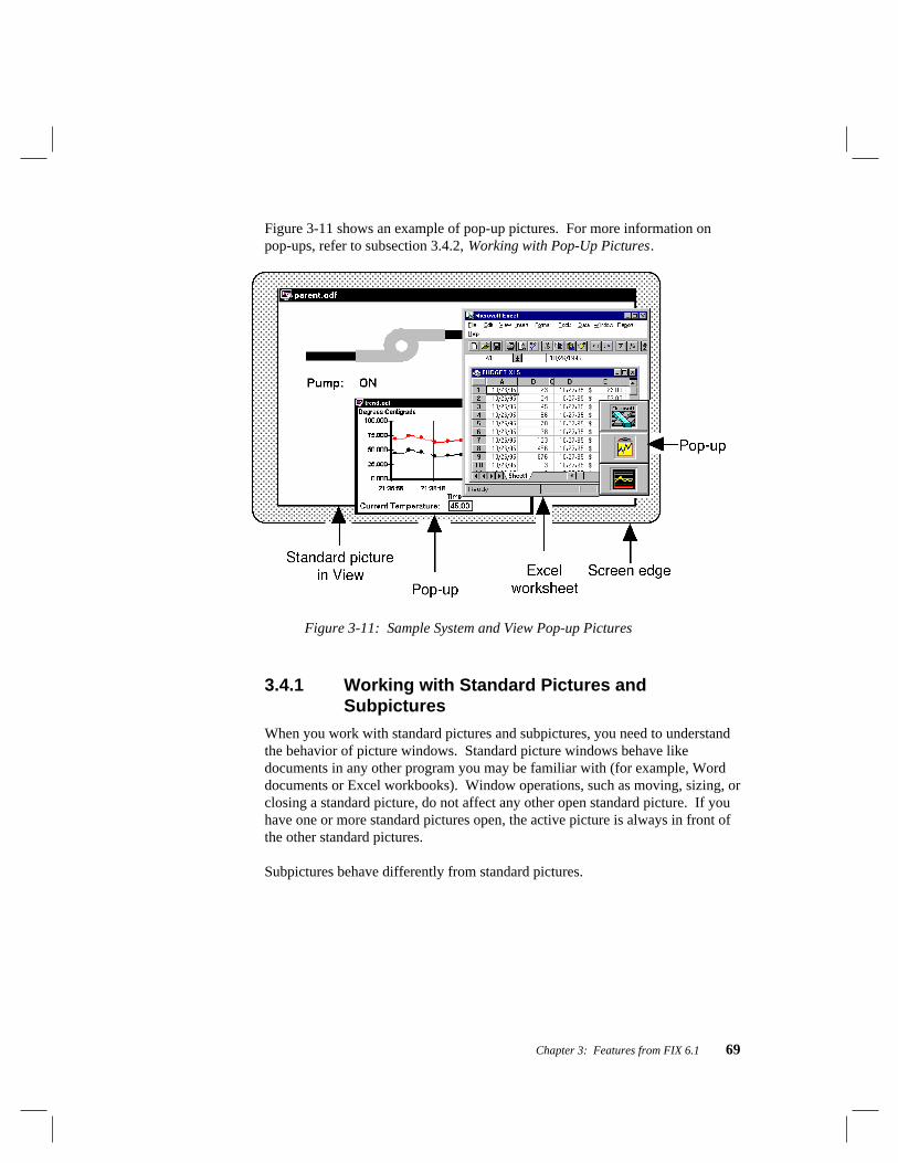
Chapter 3: Features from FIX 6.1 69
Figure 3-11 shows an example of pop-up pictures. For more information onpop-ups, refer to subsection 3.4.2, Working with Pop-Up Pictures.
Figure 3-11: Sample System and View Pop-up Pictures
3.4.1 Working with Standard Pictures andSubpictures
When you work with standard pictures and subpictures, you need to understandthe behavior of picture windows. Standard picture windows behave likedocuments in any other program you may be familiar with (for example, Worddocuments or Excel workbooks). Window operations, such as moving, sizing, orclosing a standard picture, do not affect any other open standard picture. If youhave one or more standard pictures open, the active picture is always in front ofthe other standard pictures.
Subpictures behave differently from standard pictures.

70 What’s New for FIX 7
Moving SubpicturesA subpicture can be moved within the area of the picture that opened it bydragging the subpicture’s title bar. If an operator moves a subpicture beyond theborder of the picture that opened it, the subpicture is clipped. Figure 3-12 showsthis concept.
Figure 3-12: Moving Subpictures Inside a Standard Picture
You can also move a subpicture by dragging the title bar of the picture thatopened it. When you move the picture that opened the subpicture, the subpicturemoves with it. Figure 3-13 shows this concept.

Chapter 3: Features from FIX 6.1 71
Figure 3-13: Moving Subpictures by Moving its Parent
Closing SubpicturesYou can close a subpicture by selecting Close from the File menu or the Systemmenu. You can also close a subpicture by closing the picture that opened it.

72 What’s New for FIX 7
Alternatively, you can provide a push button to close a subpicture using acommand language script with the CLOSEPIC or REPLACEPIC commands.Refer to the Command Language Manual for more information on using thesecommands.
3.4.2 Working with Pop-Up Pictures
Pop-up pictures can be set up in one of two ways. By default, pop-up picturesare always in front of all currently open FIX pictures. However, pop-up picturescan also be configured to be always on top. When this option is selected for apop-up picture, it remains in front of all open windows from all applications.
Working with pop-up picture windows is similar to working with standardpicture windows. For example, window operations, such as moving, sizing, orclosing a pop-up picture, do not affect any other open picture. However, unlikestandard pictures and subpictures, pop-up picture move independently fromView, as Figure 3-14 shows.

Chapter 3: Features from FIX 6.1 73
Figure 3-14: Moving Pop-up Pictures

74 What’s New for FIX 7
3.4.3 Specifying the Picture Type
You can specify the type of picture you want to create as follows:
[1] Start Draw.
[2] Select Picture from the Edit menu. The Picture dialog box appears, asshown in Figure 3-15.
[3] Select one of the picture type option buttons as Table 3-2 describes.
Table 3-2: Selecting the Picture Type
To create a… Select the…
Standard picture Standard option button.
Subpicture Subpicture option button.
Pop-up picture Pop-up option button.
Pop-up picture that isalways on top
Pop-up option button and theAlways on top check box.
After specifying the picture type, select one or more window properties for thepicture. Proceed to subsection 3.4.4,Window Properties for Pictures, todetermine which window properties you need.
3.4.4 Window Properties for Pictures
Draw provides the following window properties for pictures:
■ Title bars
■ System Menus
■ Sizing Borders
■ Always on Top

Chapter 3: Features from FIX 6.1 75
Not all properties are available for all pictures. The type of picture dictates theavailable properties. Each of these properties can be turned on or off, allowingyou to create the exact look and feel you want.
For example, you can:
■ Simulate dialog boxes by creating pop-up pictures with the title bar andSystem Menu enabled.
■ Create a tool palette for operators using a pop-up picture with the sizingborders and System Menu disabled.
■ Create an opening title screen by creating a standard picture with eachwindow property disabled.
3.4.5 Selecting Window Properties for Pictures
To enable or disable a window property:
[1] Start Draw.
[2] Select Picture from the Edit menu. The Picture dialog box appears.
[3] Select a Window Property check box, shown in Figure 3-15.

76 What’s New for FIX 7
Figure 3-15: The Picture Dialog Box
After specifying the window properties for your picture, you can close thePicture dialog box, add the objects you want to the picture, and save it. Refer tothe Draw Manual for additional information on accomplishing these tasks.
3.5 Saving Settings in DRAW
3.5.1 Color Threshold Settings
The color threshold table settings are now global in Draw. The settings youconfigure from the Color Threshold Definition dialog box now become thedefault for all pictures created in Draw.
3.5.2 Grid Settings
The grid spacing setting is now saved by Draw with each picture. The gridspacing set for each individual picture is restored when that picture is re-opened.
Chapter 3: Features from FIX 6.1 77
The show grid and snap-to-grid settings are now global in Draw. The settingsyou configure from the pull-down menus now become the default for all picturescreated and opened in Draw.
NOTE: Both the color threshold settings and the grid settings should beconfigured from within Draw. Do not attempt to alter these settings by editingthe DRAW.INI file.
3.6 RESOLVEVARS CommandPurposeThe RESOLVEVARS command causes all variables in a picture to be resolvedto the most current assignment.
Syntax
RESOLVEVARS picture
ExampleIn earlier versions of FIX, once a variable had been assigned a validnode:tag.field string, that assignment was permanent. You could assign a newnode:tag.field string to that variable, but View would continue to display databased on the original assignment. For example, if in a Commands on Openscript you made the following assignment:
DECLARE #abc string picture#abc = "THISNODE:AI1.F_CV"
then a Data link referencing #abc would display the current value forTHISNODE:AI1.F_CV.
However, if a later line in the command script reassigned the variable:
#abc = "THISNODE:AI2.F_CV"
then View would continue to display the value for THISNODE:AI1.F_CV.

78 What’s New for FIX 7
Now if you add the new RESOLVEVARS command to the sample script:
#abc = "THISNODE:AI2.F_CV"RESOLVEVARS*
then as soon as the RESOLVEVARS command is executed, View immediately displays thecurrent value of THISNODE:AI2.F_CV in any Data link referencing #abc.
3.7 Alarm Summary EnhancementsSeveral enhancements have been made to the Alarm Summary, including:
■ New alarm color
■ Manual alarm deletion
■ Filter by node:tag with wildcards
■ Date In and Date Last columns
■ Alarm Startup Queue synchronization
These features are described in the following subsections.
3.7.1 New Alarm Color
The new alarm color function allows you to configure a single foreground colorto be used for new (unacknowledged) alarms. A new alarm is displayed usingthis color until it is acknowledged. Once the alarm is acknowledged, it iscolored based on the color assigned to its latched alarm state. The alarm’sbackground color will continue to reflect its alarm priority.
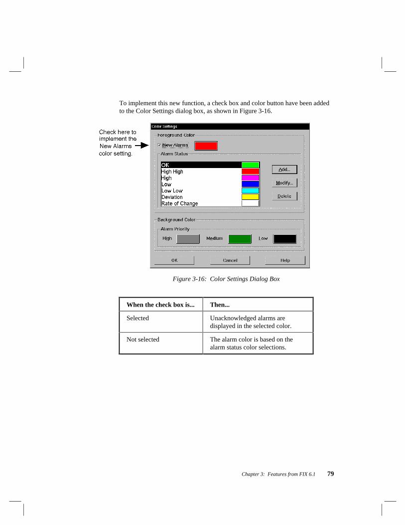
Chapter 3: Features from FIX 6.1 79
To implement this new function, a check box and color button have been addedto the Color Settings dialog box, as shown in Figure 3-16.
Figure 3-16: Color Settings Dialog Box
When the check box is... Then...
Selected Unacknowledged alarms aredisplayed in the selected color.
Not selected The alarm color is based on thealarm status color selections.

80 What’s New for FIX 7
3.7.2 Manual Alarm Deletion
Previously, when an alarm returned to normal, the Alarm Summary linkautomatically deleted it from the summary queue. The user now has the optionof maintaining this automatic deletion feature or manually deleting individualalarms.
When Manual Alarm deletion is enabled, alarms are deleted by being re-acknowledged. This can only be done to an alarm that has been previouslyacknowledged and has returned to normal. Any of the following three methodsmay be used to acknowledge an alarm.
■ Double-click the alarm in the Alarm Summary link.
■ Select the alarm and use the Acknowledge One command from theAlarms menu or right-click the mouse and select the command from thepop-up menu that appears. The Acknowledge All command cannot beused.
■ Attach a command script, with the MENU ACKNOWLEDGE_ONEcommand included, to a pushbutton. The pushbutton can then be used torun the command and acknowledge the alarm.
IMPORTANT: To use the manual alarm delete feature, both the SCADA nodeand the nodes reporting the alarms must be using FIX v6.1 or greater.
To implement manual alarm deletion:
[1] Start the SCU. Click the Alarm icon or select Alarms from the Configuremenu. The Alarm Configuration dialog box appears.
[2] Select Alarm Summary Service from the list of alarm tasks. If AlarmSummary Service is not enabled, do so now by selecting the Enableoption button from the Status section of the dialog box.
[3] Click the Modify button. This opens the Alarm Summary ServiceConfiguration dialog box.

Chapter 3: Features from FIX 6.1 81
[4] Select the Manual radio button from the Alarm Deletion section of thedialog box.
[5] Click OK to exit the Alarm Summary Service Configuration dialog box,then click OK, again, to exit the Alarm Configuration dialog box.
All Alarm Summary links in all pictures opened on the node will delete alarmsthe same way. When an alarm is manually deleted, this information isdistributed so that the alarm is deleted from all Alarm Summary links on thenode, as well as from all other nodes with manual alarm deletion enabled. Onnodes with manual alarm deletion disabled, the alarm would already have beendeleted.
3.7.3 Filter by Node:Tag with Wildcards
You can now specify a pattern for a node:tag combination that determines whichalarms are displayed in the alarm summary link. Only those alarms whose nodename and tag name match the pattern are included; all other alarms are filtered.This feature must be configured individually for each Alarm Summary link.
The asterisk (*) wildcard character can be used in the node and/or the tagspecification to create the pattern. In fact, the wildcard character can be usedtwice in the pattern: once in the node name and once in the tag name. Thewildcard character must be at the beginning or the end of the node or tag name.

82 What’s New for FIX 7
For examples of how this new filtering feature works, see the following table.
This Node:TagPattern...
Matches...
area*:level* Tags that begin with level on nodes thatbegin with area
*area:*level Tags that end with level on nodes that endwith area
*:temp* Tags that begin with temp on all nodes
*:status Tags called status on all nodes
*oven:* All tags on nodes that end with oven
tank:* All tags on the node called tank
*:* All tags on all nodes (or no filtering)
3.7.4 Date In and Date Last Columns
In Draw, you use the Alarm Summary Configuration dialog box to filter thealarms that are displayed in the Alarm Summary List. From this dialog box youcan reach the Column Format dialog box, shown in Figure 3-17, and specify thecolumns that appear in the list. Two new columns are available: Date In andDate Last.

Chapter 3: Features from FIX 6.1 83
Figure 3-17: Column Format Dialog Box
When the Date In check box is selected, a column with this title is included inthe Alarm Summary link that shows the date when the alarm was first generatedby the block. When the Date Last check box is selected, a column with this titleis included in the Alarm Summary Link that shows the date when the last alarmwas generated by the block.
3.7.5 Alarm Startup Queue
The Alarm Startup Queue has been enhanced so that summary alarms on a Viewnode may be synchronized with those on a SCADA node. Essentially, theSCADA node takes a “snapshot” of the existing alarms and sends thatinformation to the View node so their queues will be identical.
In addition to this improvement, the Startup Queue Configuration dialog box hasbeen expanded, as shown in Figure 3-18.

84 What’s New for FIX 7
Figure 3-18: Startup Queue Configuration Dialog Box
By default, the Summary alarms only check box is selected. To receiveadditional alarms, you must clear the check box. To filter alarms by time, selectthe Enable time filter box and enter the appropriate numbers in the Hours andMinutes boxes.
3.8 Alarm File Service - Number of Daysbefore Alarm File Deletion
The number of days before the automatic deletion of alarm files can be set byediting the ALARM.INI file, which is located in the Local path of the FIXdirectory. To edit this file, change the value of the keyword “file_live_days” tobe equal to the desired number of days. For example:
file_live_days=60
The valid range is from 1 to 365. Fractional numbers are rounded down, whileout of range values and other invalid entries cause the value to default to 30.Non-existence of the .INI file also sets the value to 30 days.
You must re-start FIX in order for this change to be enabled.

Chapter 3: Features from FIX 6.1 85
3.9 Remote Alarm FilteringThe remote alarm-filtering enhancement allows you to filter alarms receivedfrom remote SCADA nodes based on plant area. This particular filteringoverrides any alarm filtering specified in the alarm type configuration.
To enable remote alarm filtering, create a text file called FILTER.ALM in thedirectory pointed to by the FIX Local path. The text file must have the followingattributes:
■ First line of the file is a comment line. This line should only contain asemicolon (;).
■ Node names separated from the alarm area by acolon (:).
■ Alarm areas are separated by a comma (,).
The following is a sample FILTER.ALM file:
;NODE1:A,B,CNODE2:NONE
In this example, the first line indicates that only alarms from database blocks inalarm areas A, B, C, or ALL configured will be accepted from NODE1. Thesecond line indicates that from NODE2, no alarms will be accepted (all will befiltered).

86 What’s New for FIX 7
3.10 New FIX Startup Command LineParameter
By default, on a SCADA node, SAC is automatically added to the SCU task listand is loaded at startup. A new command line parameter, /O or /o, has beenadded so that you can prevent SAC from loading.
NOTE: This command line uses the letter “o” and not zero.
To prevent SAC from loading at FIX Startup:
[1] Right-click the FIX Startup Shortcut icon and select Properties from thepop-up menu. When the Properties dialog box opens, click the Shortcuttab.
[2] Add the /O parameter to the end of the Command Line.
[3] Click OK.
NOTE: LDBA.DLL is not loaded at startup when you include the command lineparameter “/O” or “/o”.
3.11 Save and Restore Automatic UpdateRates in Historical Trending
Previously, you had the ability to set the update rate of a historical chart byselecting a 1, 2, or 5 minute Auto Update from the Options menu. This selectionreflected the refresh time for a chart for that session only. The new enhancementallows you to save the update rate. When HTD is restarted, it detects thepreviously saved update rate and restores it when the chart re-opens.
If an Auto Update rate has been selected and saved previously, thecorresponding auto update icon becomes visible at the upper right-hand cornerof the chart, and the chart updates at that rate.

Chapter 3: Features from FIX 6.1 87
3.12 Select by Block Type DescriptionIn earlier versions of FIX, when you added a block, either from the FIXDatabase Builder or Draw, you could select the block type you wanted by usingthe abbreviated block type name only. For example, to add an Analog Inputblock, you entered AI. This enhancement allows you to select a block typebased on the block type description, as well as the abbreviated block type name.
The search is case insensitive, will allow for partial matches, and will return thefirst matching entry.
For example, if you type the word Analog, the Analog Alarm dialog boxappears. Using this dialog box, you can configure an Analog Alarm Block. Bychanging your entry to Analog O, you can display an Analog Output dialog boxand configure an Analog Output block.
3.13 Introducing FIX Electronic BooksFIX includes a library of electronic books designed to help you find theinformation you need quickly and conveniently. FIX Electronic Books replaceprinted documentation.
NOTE: FIX Electronic Books let you print sections, multiple sections, or entirebooks. Traditional printed documentation is also available upon request.Contact your FIX sales representative to order printed documentation.
Intellution encourages you to use FIX Electronic Books and the FIX product’sonline help to assist you with setup and development tasks. The followingmanuals will be available as electronic books:
System Setup System Development
Introduction to FIX Systems Database Builder Manual
Basics Manual Database Reference Manual
Environment Setup Manual Alarming and Messaging Manual
Network Manual Security Manual
System Configuration Manual

88 What’s New for FIX 7
Display Development Advanced Tools
Draw Manual DDE Support Manual
Macro Editor Manual Historical Trending Manual
Command Language Manual Recipe Manual
Tag Group Editor Manual Real-Time ODBC SQL Manual
View Manual Real-Time ODBC SQLApplication Manual
Intellution uses the DynaText system, developed by Electronic BookTechnologies, Inc. (EBT), to display FIX Electronic Books.
3.13.1 Electronic Book Features
FIX Electronic Books offer a variety of features that let you quickly find theinformation you need. Having the documentation set at your fingertips whileworking with the FIX lets you work more efficiently.
In addition to having immediate access to product questions, you also have theability to move quickly to related information, view multiple books at once, andsearch with extraordinary speed. Other FIX Electronic Book features let you:
■ Use a collapsible and expandable hypertext Table of Contents thatprovides quick navigation through the electronic book.
■ View all graphics within any book from a custom Table of Contents andzoom into any graphic to display an enlarged view of a particular section.
■ Search across all books, or within individual books, with a powerfulengine that provides immediate feedback by:
❏ Providing a “hits list”.
❏ Highlighting all instances of the result in line.
❏ Scrolling to the first occurrence of the result.
■ Selectively print a section, multiple sections, or an entire book ondemand.

Chapter 3: Features from FIX 6.1 89
■ Customize electronic books by adding your own annotations, bookmarks,and hypertext links.
■ Copy text to any word processor or text editor and export text to a file.
The following sections provide the steps you need to use some of the features inFIX Electronic Books. For detailed information on DynaText browser, click theReader Guide command from the Help menu at any time while you are usingFIX Electronic Books.
3.13.2 Opening an Electronic Book
Use the following steps to open any FIX Electronic Book:
[1] Double-click the FIX Electronic Books icon from your FIX ProgramGroup or select Electronic Books from the Help menu of any FIXapplication.
[2] Double-click any manual title listed in the FIX Electronic BookCollection window.
NOTE: If you need to move the location of FIX Electronic books, you mustdelete the Books directory (by default \FIX32\EBOOKS) and all itssubdirectories. Then, reinstall the FIX Electronic Books option from the FIXCD-ROM.
3.13.3 Using the Status Bar
The sections that follow provide an overview of the steps you need to use someof the features in FIX Electronic Books. For detailed information on DynaTextbrowser, click the Reader Guide command from the Help menu at any time.
In addition, remember to use the status bar to quickly get information on anyselected menu command or toolbar button. The status bar is located at thebottom of the FIX Electronic Book Collection window and any book window.

90 What’s New for FIX 7
For example, when you click the Toolbar’s flashlight button inside anyelectronic book, the following help text is displayed in the Status bar:
"Search the book for the entered word or phrase”
3.13.4 Using the Full Text Search Tool
FIX Electronic Books provide a powerful and flexible full text search tool. Thistool lets you search for occurrences of words, phrases, and patterns (regularexpressions) across multiple books and within individual books.
You can access the search tool with any of the following methods:
Table 3-3: Full Text Search Methods
Search Method Description
The Find Field The Find field, located at the bottom ofboth the Collection window and eachbook window, provides quick access tothe search tool’s capabilities.
The Search Form orSearch Historycommand
These commands, which are located onthe Book menu, provide access to a list ofyour previous searches and to specialsearch forms provided for FIX ElectronicBooks.
FIX ElectronicBook Search Forms
Search Forms, accessed from thecommands described above, provide aquick method for you to execute:
■ proximity searches.
■ searches only within chapter andsection headings.
■ searches only within tables.
■ searches only within figures.

Chapter 3: Features from FIX 6.1 91
When you execute a search using any of the above methods, the browser willreport back search results via a “hits list”. A “hits list” produces the number oftimes the search result is found in a given book or section. The Collectionwindow provides a Hits column to display this information. Within a book, the“hits list” appears along the left side of the Table of Contents at each sectionwhere the result can be found.
You can also set preferences for how you want the search tool to performsearches and report results. These preferences apply to both searching acrossbooks and searching within individual books.
Select Preferences from the File menu and click the Searching category to setsearch tool preferences. Preferences include the ability to:
■ Turn the “hits list” displayed in a book’s Table of Contents on or off.
■ Receive search results feedback in terms of relevance instead of actualhits. In other words, the Relevance option lets the search tool provideresults in terms of a ranking order that is proportional to the number ofactual hits. So, the “hits list” numbers will show you which sections havethe most hits by assigning a ranking number to sections with the most, theleast, and so on.
■ Decide whether the search tool looks for the word exactly as you type itor whether it locates words with and without accents.
3.13.5 Customizing an Electronic Book
You can customize a FIX Electronic Book in a number of ways, including:
■ Marking sections with a bookmark.
■ Adding a custom note or annotation to a particular section of a book.
■ Creating cross-references (hyperlinks) between two different locations ina book.

92 What’s New for FIX 7
Any customization you make to an electronic book is stored in either a public ora private directory. You can choose where to save a bookmark, annotation, orcross-reference when you create it. The FIX installation process automaticallycreates public and private directories for you.
NOTE: You should save customizations to the public directory only when youinstall the FIX Electronic Books on a network server. Keep in mind that thenetwork drive must have writing privileges enabled in order to do this.
BookmarksUse the following steps to create a bookmark:
[1] Click and drag to highlight the text that you want to mark.
[2] Click the Mark button in the button bar, or select Create Annotation andthen Create Bookmark from the Book menu.
[3] Select either the Public or Private button.
[4] Type the name of the bookmark in the text field and click OK.
AnnotationsUse the following steps to create an annotation:
[1] Position the cursor at the location where you want to add the note.
[2] Click the Note button in the button bar, or select Create Annotation andthen Create Note from the Book menu.
[3] Select either the Public or Private button.
[4] Type the name of the note in the text field and click OK.
[5] Type the text you want to save in the note.
NOTE: You can copy text from the electronic book into your note. To do this,click and drag the mouse to select the text that you want to copy. Press<Ctrl><C> or select Copy from the Edit menu. Then, position the cursor in thetext field of the Note dialog box and press <Ctrl><V> or select Paste from theEdit menu.

Chapter 3: Features from FIX 6.1 93
[6] Select the Close command from the Window menu when you are finishedand select Yes to save your changes.
Hyperlinks
[1] Position the cursor at the location where you want to start the hyperlink.
[2] Click the StartLink button in the button bar, or select Create Annotationand then Start Hyperlink from the Book menu. As a result, the origin ofthe hyperlink is set to the location of the selected text.
NOTE: An icon to represent the hyperlink is not displayed in the marginat this time.
[3] Move to the text in the document that you want to be the target of thehyperlink. Position the cursor at the location where you want to end thehyperlink.
[4] Click the EndLink button in the button bar, or select Create Annotationand then End Hyperlink from the Book menu. As a result, the destinationof the hyperlink is set to the location of the selected text.
[5] Select either the Public or Private button.
[6] Select either One-Way or Two-Way.
One-way (unidirectional) links allow you to jump in one direction fromthe origin to the destination of the link. Two-way (bi-directional) linksallow you to jump in either direction between the origin and thedestination
[7] Type the name of the hyperlink and click OK.

94 What’s New for FIX 7
3.13.6 Copying and Pasting Information BetweenApplications
FIX Electronic Books let you copy information to and paste information fromthe Windows clipboard. These features let you:
■ Design custom annotations that include information from other Windowsapplications.
■ Include electronic book information in word processing documents orspreadsheets.
Use the following steps to copy and paste text from any electronic book:
[1] Click and drag the mouse to select the text that you want to copy.
[2] Press <Ctrl><C> or select Copy from the Edit menu.
[3] Decide where you want to paste the information:
■ To paste the text into an existing note annotation, move to the section withthe annotation, click the icon to open the note, and press <Ctrl><V>.
■ To paste the text into a new annotation, use the steps in subsection 3.13.5,Customizing an Electronic Book, to create the annotation and press<Ctrl><V> inside the annotation window.
■ To paste the text into a word processor or other Windows application,access the application and use the application’s Paste command.

Chapter 4: Features from FIX 6.0 95
4. Features from FIX 6.0FIX v6.0 extends the power of FIX software by providing the following:
■ FIX running as a service under Windows NT.
■ FIX Mission Control.
■ Endpoint Position dynamic property.
■ New command language variables.
■ OPENBDF command.
■ Local node aliasing.
■ Tag name syntax.
The features listed above are described in the following sections.
NOTE: These features were new for v6.0 and are still present in FIX 7.
4.1 Running FIX as a Service underWindows NT
FIX can be run as a service under Windows NT. When enabled, this optionallows you to log out of NT without shutting down core FIX tasks likenetworking, SAC processing, alarming, historical collection, and I/O drivercontrol. This provides a much higher level of security to your process, becauseoperators can log in and log out of an NT node before and after their shiftwithout affecting the process.
There are two procedures for configuring FIX to run as a service:
■ Enabling the FIX as a service option.
■ Configuring tasks that you want to run as a service as background tasks.
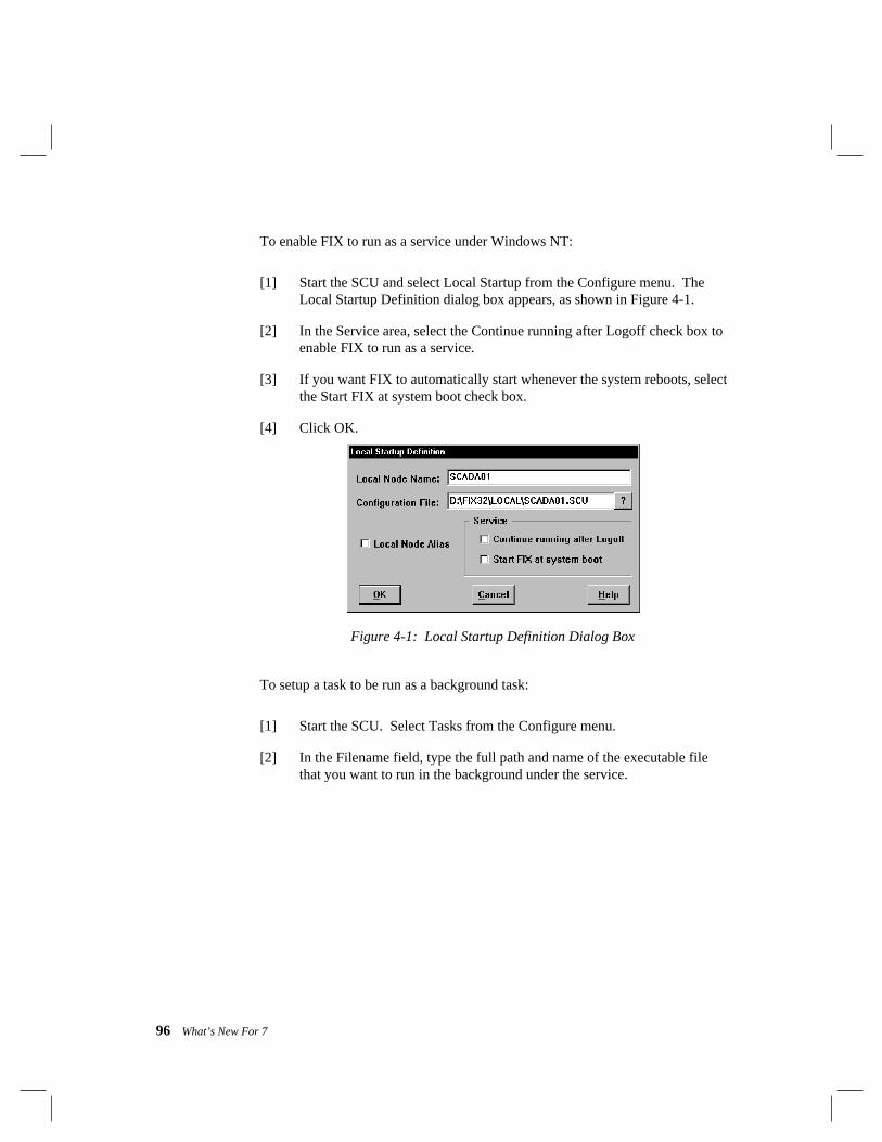
96 What’s New For 7
To enable FIX to run as a service under Windows NT:
[1] Start the SCU and select Local Startup from the Configure menu. TheLocal Startup Definition dialog box appears, as shown in Figure 4-1.
[2] In the Service area, select the Continue running after Logoff check box toenable FIX to run as a service.
[3] If you want FIX to automatically start whenever the system reboots, selectthe Start FIX at system boot check box.
[4] Click OK.
Figure 4-1: Local Startup Definition Dialog Box
To setup a task to be run as a background task:
[1] Start the SCU. Select Tasks from the Configure menu.
[2] In the Filename field, type the full path and name of the executable filethat you want to run in the background under the service.

Chapter 4: Features from FIX 6.0 97
[3] Click the Add button to add the task to the Configured Tasks list box.
[4] With the task selected in the Configured Tasks list box, selectBackground from the Start Up Mode area. A percent sign (%) appears tothe left of the task name to show that it is configured as a backgroundtask.
NOTE: You should only configure the following FIX tasks as backgroundtasks:
■ SAC (WSACTASK.EXE)■ Historical Collect (HTC.EXE)■ SQL Task (WSQLODC.EXE)■ I/O Control (IOCNTRL.EXE)
All of these files are located in the FIX Base path.
[5] Click OK. Save and exit the SCU.
[6] Restart FIX to run FIX as a service under Windows NT. When properlyconfigured, the titlebar of the FIX Startup dialog box displays FIX Startup- SERVICE MODE.
4.2 FIX Mission ControlFIX Mission Control provides an easy to use interface for monitoring thefollowing FIX background tasks:
■ SAC processing
■ SQL task
■ Historical Collect
■ I/O Control
FIX Mission Control provides you with a window into your system. Theinformation provided in Mission Control can help you diagnose potentialproblems with your FIX system, or can help you improve performance on yournode.

98 What’s New For 7
To start FIX Mission Control, select Mission Control from the Apps menu inDraw. The Mission Control dialog box appears.
Figure 4-2: FIX Mission Control
To access a particular background task, select its tab from the Mission Controldialog box. Each tab is summarized below:
I/O Control - allows you to monitor I/O driver communications statistics anderrors. For a description of these fields, refer to your I/O driver manual.
HTC - allows you to start and stop the Historical Collect background task. Alsoprovides you with an Overrun counter. The Overrun counter incrementsby one every time a historical collection fails. By examining the numberof HTC overruns, you can find out if there is a problem in your collectionscheme.

Chapter 4: Features from FIX 6.0 99
SAC - allows you to start and stop the SAC (Scan, Alarm, and Control) task, andalso provides SAC statistics that may help you troubleshoot your FIXsystem. For example, the Blocks/Sec field can be used to monitor theamount of blocks that are scanned per second. If the number fluctuatesdrastically, the blocks in your FIX database may not be properly phased.See the Database Builder Manual for more information on phasing.
SQL - allows you to start and stop the SQL task, and also provides SQLinformation to help you monitor your SQL connections to relationaldatabases. For more information on the SQL task, see the Real-TimeODBC SQL Application Manual.
4.3 Endpoint Position Dynamic PropertyA new dynamic property, called the Endpoint Position property, has been addedto FIX v6.0. The Endpoint Position property is similar to the existing Horizontaland Vertical Position properties, except that the Endpoint Position property isapplicable to the endpoints of a line rather than to an entire object. This sectiondescribes the new Endpoint Position property.
Understanding Dynamic MovementDynamic movement properties work by comparing the current value of thespecified tagname to the specified limit range. As the database value changes,the object or endpoint moves to a new position. If the database value changesfrequently enough, the object or endpoint appears to be moving on the screen.The table below describes the calculations View makes to execute dynamicmovement:

100 What’s New For 7
Step Example
[1] View fetches the tag’scurrent value.
Current Value
150
[2] View calculates thelimit range.
Limit Range = High Limit - Low Limit
200 = 300 - 100
[3] View calculates thecurrent value’s percentof the limit range.
Value Percent = [(Current Value - LowLimit) / Limit Range] * 100
25 = [(150 - 100) / 200] * 100
[4] View calculates themovement range.
Movement Range = Max. Offset - Min.Offset
2 = 4.5 - 2.5
[5] View calculates the newoffset.
New Offset = Min. Offset + (Value Percent * Movement Range)
3 = 2.5 + (.25 * 2)
View determines the direction of the movement by the sign of the entries in theoffset fields. A positive vertical change moves the object or endpoint down; anegative vertical change moves the object or endpoint up. Likewise, a positivehorizontal change moves the object or endpoint to the right; a negativehorizontal change moves the object or endpoint to the left. Figure 4-3 illustratesthis concept.
Figure 4-3: Dynamic Movement with Positive and Negative Offsets

Chapter 4: Features from FIX 6.0 101
4.3.1 Understanding Input Properties
When enabled, the Input Properties feature allows operators to change databasevalues by manipulating an object or endpoint in View. As you drag the object orendpoint, View writes new values to the database. Note that the database tagattributed to the object or endpoint must be on scan for the Input Properties towork in View.
If Allow Input Properties is enabled, all current value links (F_CV) that accessthe same database endpoint update as you drag the object. Links that access thesame database endpoint through a tag group symbol or a non-current value fieldupdate only after you finish dragging the object.
Reconfiguring Input PropertiesYou can configure by what method and how often View sends updated values tothe database by modifying the Input Dynamics section of the VIEW.INI file. Bydefault, View writes a value to the database at a specified interval while you aredragging the mouse and pressing the left mouse button. Refer to the DrawManual for more information on the VIEW.INI file.
4.3.2 Applying Dynamic Movement to the Endpointof a Line
The procedure outlined in this subsection describes how to apply dynamichorizontal, vertical, and diagonal movement to an endpoint of a line. Thisprocedure is very similar to applying dynamic movement properties to an objectexcept that an endpoint’s Horizontal and Vertical Position properties are bothconfigured in the same dialog box.
The procedure for drawing a line, as described in the Draw Manual is to clickthe Line tool, move the cursor to where you want the line to start, click and dragthe mouse until the line is the desired length, and release the mouse button tocomplete the line. Draw designates the point where you clicked to start the lineas Endpoint 1, and the point where you released the mouse button after draggingas Endpoint 2. For example, if you draw a line from left to right, the leftendpoint is Endpoint 1 and the right endpoint is Endpoint 2.

102 What’s New For 7
To use either property:
[1] From the Dynamic Properties dialog box, click the icon button next toEndpoint Position property you want to use. Figure 4-4 shows theEndpoint 1 Position dialog box.
Figure 4-4: Endpoint 1 Position Dialog Box
NOTE: Although the dialog box shown in this subsection is specific tothe Endpoint 1 Position property, you can use the same procedure toapply the Endpoint 2 Position property.
[2] Enter the target tag in the Tagname field or select the ? button to selectfrom the Field Select dialog box. The default SCADA node and field areconfigured automatically. If you want to configure a different node andfield, enter the entire tagname in node:tag.field format. The field must bein floating point format (F_). If you enter a tag that does not exist, youare prompted to add the tag to the database. You can also enter avariable, tag group symbol, or DDE address.
[3] Enter the low limit in the Low Limit field. The default is 0.

Chapter 4: Features from FIX 6.0 103
[4] Enter the high limit in the High Limit field. The default is 100.
TIP: Click the Fetch Limits button to retrieve both tags’ high and lowEGU limits. Alternatively, you can enter 0 in both the High and LowLimit fields to have View automatically fetch both tags’ EGU limits whenthe picture is opened.
[5] Calculate the number of inches that you want the endpoint to move fromits origin when the tag equals the low limit entry. Enter that number in theMinimum Offset field. Use positive or negative numbers to controldirection. If you use a large enough offset, the endpoint can actuallymove off screen.
[6] Calculate the number of inches that you want the endpoint to move fromits origin when the tag equals the high limit entry. Enter that number inthe Maximum Offset field. Use positive or negative numbers to controldirection.
TIP: For best performance, position the endpoint in Draw at oneextreme of the movement range, enter a 0 into the Minimum Offset field,and specify a positive or negative number in the Maximum Offset field.
[7] Enable the Allow Input Properties check box if you want operators towrite database values by dragging the endpoint in View. Note that the tagattributed to the endpoint must be on scan for the input properties to takeeffect.
NOTE: You cannot use a numeric variable or DDE address forEndpoint Position dynamic properties if Allow Input Properties isenabled.
Figure 4-5 illustrates the three types of dynamic movement that you can attributeto an endpoint of a line, and the tagname field that corresponds to each type ofmovement.

104 What’s New For 7
To create this type ofmovement...
Configure...
Horizontal Movement The Tagname (X) field of theEndpoint Position 1 dialog box.
Vertical Movement
The Tagname (Y) field of theEndpoint Position 1 dialog box.
Diagonal Movement Both the Tagname (X) andTagname (Y) fields of theEndpoint Position 1 dialog box.
Figure 4-5: Examples of Endpoint Dynamic Movement
4.4 Command Language VariablesTwo new types of command language variables have been added to the FIX v6.0release - the current shadow picture scope variable and the use of variables aspicture coordinates in OPENPIC commands. These variables are discussed inmore detail in the following subsections.
4.4.1 Current Shadow Predefined Variable
The Command Language provides a set of read-only, predefined variables.These variables let you access both system and picture information from acommand language script.

Chapter 4: Features from FIX 6.0 105
The following types of predefined variables are available:
Global scope variables — available to any command language script whileView is running. View maintains one copy of these variables for allscripts. Global scope variables begin with the prefix #GS_ (for stringvariables) or #GN_ (for numeric variables).
Picture scope variables — available to command language scripts running in agiven picture. View maintains multiple copies of these variables, one perpicture. This means the value of each picture scope variable changes asyou switch from one picture to another. Picture scope variables beginwith the prefix #PS_ (for string variables) or #PN_ (for numericvariables).
Current Shadow VariableA new picture scope variable, which is called the current shadow variable, hasbeen added to FIX v6.0. The current shadow variable can be used to store thetagname, variable name, or DDE address of the currently shadowed object orlink. (An object or link is shadowed when the mouse passes over it in View anda single highlighted box surrounds it.)
For example, if a dynamic object is shadowed in View, and a variable has beendefined in the dynamic property’s tagname field, #PS_CUR_SHDW stores thename of the variable. Note that if a string variable or a tag group symbolcontains a tagname, #PS_CUR_SHDW stores the tagname, not the name of thestring variable or tag group symbol. To use the #PS_CUR_SHDW variable, theShadow statement in the [Highlight] section of the VIEW.INI file must be set toTRUE (which is the default).
4.4.2 Picture Coordinate Variables
When using the OPENPIC command, you can specify the picture placement,height, and width coordinates of the picture that you want to open. In FIX v6.0,you can now use variables and tag groups for these coordinates. A reviseddescription of the OPENPIC command is provided in this section.

106 What’s New For 7
PurposeThe OPENPIC command opens a selected picture in View. If used as a relativecommand, the selected picture opens.
NOTE: When a relative OPENPIC command is included in a commandlanguage script, the File Open dialog box appears and prompts the operator toenter a picture name.
Syntax
OPENPIC picture [Y,X,W,H] [nickname] [tag group file]
Parameterspicture — specifies the name of the picture to be opened. A string variable ortag group can replace this parameter.
Y,X,W,H — specifies the picture placement, height, and width in pixels, where100 pixels equals 1 logical inch. Use the following guidelines whendefining these parameters:
■ Numeric variables and tag group symbols can be substitutedfor any of the Y, X, W, and H parameters.
■ The X and Y offsets can be positive or negative wholenumbers, but cannot exceed the limits of the display. Forexample, if your display is VGA, the lowest XY offset you canspecify is 0,0 and the highest is 640,480.
■ The H and W offsets must be greater than or equal to 20.
■ When the picture placement parameter is not used, but isfollowed by other parameters, a -1 must be used as aplaceholder.

Chapter 4: Features from FIX 6.0 107
■ If you are opening a picture with a title bar, any height andwidth values specified in this parameter override the valuesspecified in the Picture Properties dialog box in Draw.
■ If you are opening a picture without a title bar, defined byremoving the title bar with the Picture Properties command inDraw, the height and width parameter is retrieved from thevalues in the Picture Properties dialog box.
TIP: Use the Cursor Position tool in Draw to calculate the pictureplacement. For example, by placing the cursor at the top left corner atwhich the picture should appear, the tool provides the exact X and Ycoordinates, in inches. Multiply each coordinate by 100 to obtain thepicture placement parameter.
NOTE: If you specify OPENPIC coordinates in a dynamo commandlanguage script, no prompt appears for the OPENPIC command.
nickname — specifies the nickname, up to 36 characters, that you want to assignto this picture. A string variable or tag group can replace this parameter.
A nickname is a user-defined, generic picture name that lets you controlthe opening and closing of multiple pictures without concern for whichpicture is currently displayed.
NOTE: If you use View’s layout commands to create picture layout files,any assigned nicknames are included in the layout file information. Referto the Draw Manual for information on creating layout files.

108 What’s New For 7
tag group file — specifies the name of the tag group file that contains all the taggroups required for the opened picture. A string variable can replace thisparameter.
NOTES: A tag group symbol used in place of this parameter must existwithin the currently loaded tag group file. Otherwise, View has noreference from which to obtain the symbol substitution. Therefore, thistechnique cannot be used for the first picture opened in View.
If you want to specify a tag group file, but not a nickname, use an asterisk(*) as a placeholder for the nickname.
ExampleAn overview display contains four push buttons that allow operators to monitorplant lines. Four keystroke macros let operators select the keys <F1> through<F4> to open each display at any time, in any order. The OPENPIC commandand a nickname assignment guarantee that only the overview display and oneline monitoring display is open at any given time.
The use of nicknames gives the script control over the opening and closing ofdisplays without regard for the exact picture name. Each time the operatorselects the appropriate function key, the keystroke macro closes any picture witha nickname of LINE, and re-assigns the nickname to the opened picture.
Each command language script includes the following:
CLOSEPIC LINEOPENPIC picture -1 LINE

Chapter 4: Features from FIX 6.0 109
4.5 New OPENBDF CommandPurposeThe OPENBDF command opens a specific tag status picture in View. For moreinformation on tag status pictures, refer to the Draw Manual.
Syntax
OPENBDF picture node:tag [Y,X,W,H] [nickname]
Parameters
picture — specifies the name of the tag status picture to be opened. A stringvariable or a tag group can replace this parameter.
node:tag — specifies the node name and tag name that you want to open in thetag status picture. A string variable or a tag group can replace thisparameter.
Y,X,W,H — specifies the picture placement, height, and width in pixels, where100 pixels equals 1 logical inch. Use the following guidelines whendefining these parameters:
■ Numeric variables and tag group symbols can be substitutedfor any of the Y, X, W, and H parameters.
■ The X and Y offsets can be positive or negative wholenumbers, but cannot exceed the limits of the display. Forexample, if your display is VGA, the lowest XY offset you canspecify is 0,0 and the highest is 640,480.
■ The H and W offsets must be greater than or equal to 20.
■ When the picture placement parameter is not used, but isfollowed by other parameters, a -1 must be used as aplaceholder.

110 What’s New For 7
■ If you are opening a picture with a title bar, any height andwidth values specified in this parameter override the valuesspecified in the Picture Properties dialog box in Draw.
■ If you are opening a picture without a title bar, defined byremoving the title bar with the Picture Properties command inDraw, the height and width parameter is retrieved from thevalues in the Picture Properties dialog box.
TIP: Use the Cursor Position tool in Draw to calculate the pictureplacement. For example, by placing the cursor at the top left corner atwhich the picture should appear, the tool provides the exact X and Ycoordinates, in inches. Multiply each coordinate by 100 to obtain thepicture placement parameter.
nickname — specifies the nickname, up to 36 characters, that you want to assignto the tag status picture. A nickname is a user-defined, generic picturename that lets you control the opening and closing of multiple pictureswithout concern for which picture is currently displayed. A stringvariable or tag group can replace this parameter.
If you use a tag group symbol in place of this parameter, the tag groupsymbol must exist within the currently loaded tag group file. Otherwise,View has no reference from which to obtain the symbol substitution.Therefore, this technique cannot be used for the first picture opened inView.
NOTE: If you use View’s layout commands to create picture layout files, anyassigned nicknames are included in the layout file information. Refer to theDraw Manual for information on creating layout files.

Chapter 4: Features from FIX 6.0 111
ExampleIn the following example, a display contains a pushbutton with a commandlanguage script that allows operators to monitor the status of an Analog Inputblock.
OPENBDF AI.BDF MYNODE:AI-1
4.6 New Tag Name SyntaxTag names can now be up to 30 characters in length and can contain severalspecial characters, including:
■ - (dash)
■ / (forward slash)
■ _ (underscore)
■ \ (back slash)
■ ! (exclamation point)
■ | (pipe)
■ # (number sign)
■ [ (open bracket)
■ % (percent sign)
■ ] (close bracket)
■ $ (dollar sign)

112 What’s New For 7
Examples:AI1CA_10DI#4PID
NOTES: Do not confuse the phrase tag name with the word tagname usedthroughout the FIX documentation. Tagname in the FIX documentation usuallyidentifies the NODE:TAG.FIELD object.
When specifying a tag name, remember that the tag name must begin with aletter or number and must contain at least one non-numeric character.
4.7 Local Node AliasingThe Local Node Alias feature allows you to substitute a placeholder,THISNODE, for the node portion of a tagname in order to automatically accessinformation from the local SCADA node. This is ideal for developing picturesthat can be shared among several computers that each access different SCADAnodes. The Basics Manual provides more in-depth information on the LocalNode Alias feature.
To use the Local Node Alias feature, you must first enable it in the Local StartupDefinition dialog box:
[1] Start the SCU and select Local Startup from the Configure menu. TheLocal Startup Definition dialog box appears, as shown in Figure 4-6.
[2] Click the Local Node Alias check box.
[3] Click OK. Save and exit the SCU.
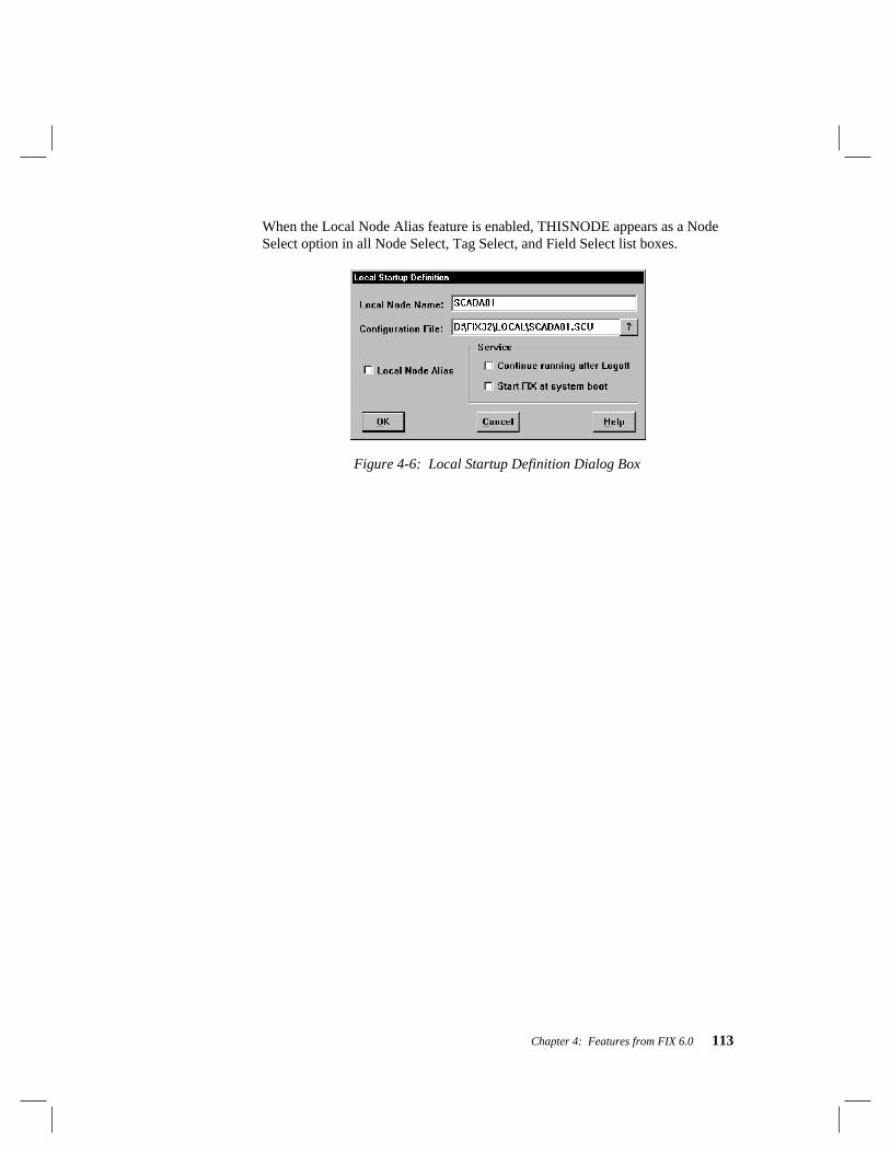
Chapter 4: Features from FIX 6.0 113
When the Local Node Alias feature is enabled, THISNODE appears as a NodeSelect option in all Node Select, Tag Select, and Field Select list boxes.
Figure 4-6: Local Startup Definition Dialog Box

114 What’s New For 7