white paper - nvidiadeveloper.download.nvidia.com/sdk/10/direct3d/source/sparkles/doc/... · the...
TRANSCRIPT
February 2007 WP-03021-001_v01
White Paper
Sparkling Effect

White Paper
ii WP-03013-001_v01 February 20, 2007
Document Change History
Version Date Responsible Reason for Change _v01 February 20, 2007 TL, TS Initial release
Go to [email protected] to provide feedback on Sparkling Effect.
WP-03013-001_v01 1 February 20, 2007
Sparkling Effects
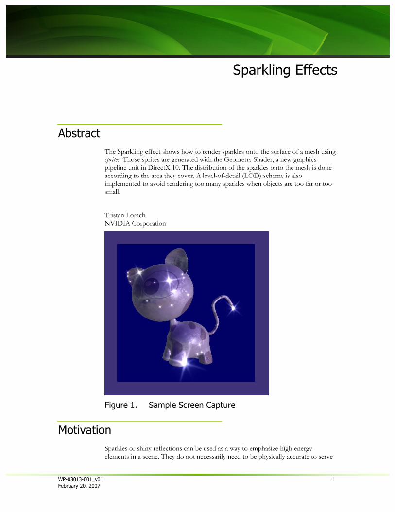
Abstract The Sparkling effect shows how to render sparkles onto the surface of a mesh using sprites. Those sprites are generated with the Geometry Shader, a new graphics pipeline unit in DirectX 10. The distribution of the sparkles onto the mesh is done according to the area they cover. A level-of-detail (LOD) scheme is also implemented to avoid rendering too many sparkles when objects are too far or too small.
Tristan Lorach NVIDIA Corporation
Figure 1. Sample Screen Capture
Motivation Sparkles or shiny reflections can be used as a way to emphasize high energy elements in a scene. They do not necessarily need to be physically accurate to serve

White Paper
2 WP-03013-001_v01 February 20, 2007
this purpose and look good. In general, the effect covered here does not generate a photo realistic sparkle effect, but would be more suited to applications which are going for a more stylized look.
If we wanted to be accurate in the mathematics of this effect, we would have to perform complex post processing calculations. In the real world, the sparkle effect on a surface is due to specific lens ‘artifacts’ where the light bounces around inside various lens layers and gets spread around a high energy point according to patterns related to the lens.
The hard part of using a post-processing approach is reproducing the circular shape of the lens, which is why you often end-up doing these lens effects aligned along the x and y axes only (and, occasionally, along the diagonals). Developers have tried to work around these issues in different ways. One effect close to this was implemented by the NVIDIA Demo Team in The Nalu (Mermaid) demo. This demo created circular light rays by moving from one Cartesian space to one circular space, where the post processing is performed in circular space, then the result is put back to Cartesian space, which turns out to be a very computationally expensive process.
The choice of technique to adopt depends on the balance between GPU work and effect accuracy. It also depends on how significant this effect is to the overall image. For example, if a small area of the scene gets saturated by the light and as a result generates such ‘sparkles’, you may not want to do post-processing on the whole screen. In this situation, the Sprite technique introduced in this paper allows you to make the effect very local.
This sample deals only with sprite rendering to fake these sparkling effects. The new generation of DirectX 10 GPU (GeForce 8800 family) now allows us to create primitives on the fly, making this approach more elegant than creation of sprites on the CPU.
Another type of sparkling is introduced in this effect using a pixel shader that implements a “car paint” type shader.
Sparkling Effect
WP-03013-001_v01 3 February 20, 2007
How It Works The sample is divided into four main parts:
1. Compute the lighting to decide how we display the sprite on top of a point (micro-surface approximation)
2. Create the sprite according to the lighting. 3. Spread points around the model, depending on density. 4. A last optional section is related to how we do flakes in the car-paint shader.
One goal of this effect is rendering sprites without changing the way we send the mesh to the GPU. We want the GPU to create the sparkling sprites from the original mesh (without modification) instead of having to feed the 3D pipeline with a pre-computed cloud of points. Thus, the whole effect uses two passes:
First pass renders the object and also computes the depth value in another render target.
Second pass renders the object again but this time the geometry shader uses it to create the sprites.
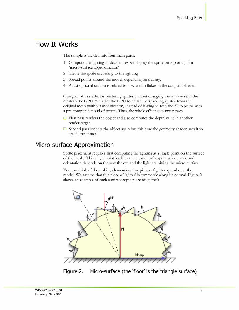
Micro-surface Approximation Sprite placement requires first computing the lighting at a single point on the surface of the mesh. This single point leads to the creation of a sprite whose scale and orientation depends on the way the eye and the light are hitting the micro-surface.
You can think of these shiny elements as tiny pieces of glitter spread over the model. We assume that this piece of ‘glitter’ is symmetric along its normal. Figure 2 shows an example of such a microscopic piece of ‘glitter’:
Figure 2. Micro-surface (the ‘floor’ is the triangle surface)

White Paper
4 WP-03013-001_v01 February 20, 2007
The whole point of this shape is to make the lighting fuzzy. The sparkling effect is coming from the broken micro-surface, so normal vectors have rapidly changing orientation. Given that you would then compute lighting by using diffuse and specular computation, this micro-surface structure causes the diffuse and specular lighting values to quickly change from one extreme to another.
The next details show how the approximation allows us to compute the final lighting contributions depending on the definition of this micro-surface.
Let’s consider N and :
N is the main normal of the surface where the piece of glitter is applied.
is the bi-normal vector of the surface. Those two vectors express the orthogonal basis we use to define the orientation (Beta) of any normal N’ onto the micro-surface. N' can then be expressed as follows:
If we consider that we have SZ small facets spread around the micro surface, Cos() and Sin() values are stored in a pre-computed table of SZ pairs of values; depending on the dot products N.L or H.N, we then refer to a pair of [Cos-Sin] values in this array of SZ size.
Here we show how we can find the index ‘d’ of the pair, depending on N.L. Then,
we can find N’ and N’.L expressed with N and :
However we may want to get rid of the binormal component and only use N in the equation. Let’s assume these two vectors are normalized:
Replacing Cos(alpha) with N.L, we end-up expressing N’ with N only.

Sparkling Effect
WP-03013-001_v01 5 February 20, 2007
We can apply the same process with the specular lighting:
Creation of the Sprite According to the Lighting The lighting computation is used to setup a sprite centered at the same place where this piece of ‘sparkling glitter’ is located.
Note that we are only using the specular part of the light: after all, the sparkling strength essentially depends on how the light is being reflected from the micro-surface.
Two components are used to setup the sprite:
Specular lighting to scale the size of the sprite. Light direction, where the sprite is aligned along the 2D projected line coinciding
with the vector : cross(LightDir, N).
This orientation gives a nice rotation of the sparkles when the object, camera, or light is moving.
The sprite is then simply rendered from its 2D projected center by shifting the corners in 2D depending on the orientation and scale (see computeSpriteCorner()).
How to Spread Points Around the Model We use a pseudo-random set of barycentric coordinates stored in a table (see RandomTable.fxh).
Figure 3. Barycentric Coords for a Set of Points
The number of sparkling points to emit in a triangle depends on its projected area (see GSSparkles_Barycentric()). If you consider v1 and v2 as the two projected vectors of two edges of a triangle :
Ns = min(0.5*(v1.x*v2.y - v2.x*v1.y) * LODScale, MaxN)

White Paper
6 WP-03013-001_v01 February 20, 2007
We read Ns barycentric coordinates from the table of pseudo-random barycentric points and define new positions and normals on the surface of the triangle (see barycentricWeights()).
To improve the result, we also want each triangle to read the pseudo-random table at different offsets. We do this by using the special system variable called ‘SV_PrimitiveID’ (id of the primitive being processed in the Geometry Shader):
offset = primID % (256.0 - MaxN )
256 is the size of the table of pre-computed barycentric coordinates. Therefore we had to substract MaxN to keep staying within the table of 256 barycentric coordinates.
When the area of the triangle becomes small, we cannot abruptly avoid drawing a sprite. If so, after a specific distance or size, the object would simply stop shining; which is not correct. So we must pick some of the triangles to draw at least one sparkling point, regardless of distance and triangle size.
We use a simple trick that takes advantage of SV_PrimitiveID again. Depending on the inverse of the projected Area, we pick some of the triangles and reject the others:
if(0 == (primID % round(1.0/projSurf))) then draw one sparkling point
Note: Note that this trick is dependent on the topology of the mesh and the order in which triangles are being sent to the pipeline.
This whole mechanism of drawing 0 to MaxN sprites depending on the triangle area is not only good for visual, but also can be particularly useful in a large scene, where we need to not overload the GPU with this effect.
Occlusion of Sprites Sprites need to be occluded by objects in the scene. However, because we assume that the shiny effect is happening within the lens, we must allow the sprite to be in front of any object. But when the center of the sprite gets overridden by some object, the whole sprite must disappear (this technique is the same as one used for lens flare).
The occlusion test needs a first pass where we store the depth values in a render target.
When this depth is available, we can perform the occlusion test by a function (OcclusionTest()) which scales down the size of the sprite:
Scale to 1.0 when the sparkling point is not occluded at all Scale to 0.0 when the sparkling point is totally occluded.
Geometry shaders do not need to produce an output. So when complete occlusion reduces scaling to zero, the geometry shader can avoid creating the sprite entirely.

Sparkling Effect
WP-03013-001_v01 7 February 20, 2007
‘Flakes’ in Car-paint Shader You can find the details of the shader in carpaint.fxh.
The car paint effect uses a 3D noise texture and does a fractal sum by fetching from the volume texture four times with four different octaves. The combination of these intensities leads to the fleck_intensity in object space.
This intensity is then combined with lighting and gives the impression of a random sub-surface structure changing the lighting.
Running the Sample This sample is easy to run. The following values are tweakable:
MinSz : minimum size of the Sprites. This means that instead of being culled when they reach 0.0, sprites always have a minimum visible size.
MaxSz : maximum size of the Sprite. This limits the size sprites that receive large specular coefficients.
LodScale : scales the area of the triangles when computing how many sprites to draw.
Shininess : shininess of the surface. No Persp : this check box shows that we can also use perspective projection to
change the size of the sprites. By default this perspective contribution is not used. If you want to activate it (un-checking the box), you will have to change the MaxSz to ~2.50 (instead of the default value set to 0.30) in order to get a decent result. This checkbox directly impacts the variable bNoPersp in the shader.
Performance This sample is using the Geometry Shader unit. Although we provide an LOD system to avoid drawing too many primitives, we must be careful to limit the number of generated sprites.
Furthermore, the sample needs two passes because the sprites are created from the original meshes.
In a real project, you may also want to use lower resolution meshes for the second pass, since you do not actually see these meshes but only the resulting sparkles.

White Paper
8 WP-03013-001_v01 February 20, 2007
Integration The integration of this effect into a full application will need you to provide the depth buffer either from the depth buffer as a resource view or by generating a depth texture from a second render target.
Then you will have to add a second pass to render the objects’ sparkle sprites. In this pass you could render lower resolution meshes.
.

NVIDIA Corporation 2701 San Tomas Expressway
Santa Clara, CA 95050 www.nvidia.com
Notice
ALL NVIDIA DESIGN SPECIFICATIONS, REFERENCE BOARDS, FILES, DRAWINGS, DIAGNOSTICS, LISTS, AND OTHER DOCUMENTS (TOGETHER AND SEPARATELY, “MATERIALS”) ARE BEING PROVIDED “AS IS.” NVIDIA MAKES NO WARRANTIES, EXPRESSED, IMPLIED, STATUTORY, OR OTHERWISE WITH RESPECT TO THE MATERIALS, AND EXPRESSLY DISCLAIMS ALL IMPLIED WARRANTIES OF NONINFRINGEMENT, MERCHANTABILITY, AND FITNESS FOR A PARTICULAR PURPOSE.
Information furnished is believed to be accurate and reliable. However, NVIDIA Corporation assumes no responsibility for the consequences of use of such information or for any infringement of patents or other rights of third parties that may result from its use. No license is granted by implication or otherwise under any patent or patent rights of NVIDIA Corporation. Specifications mentioned in this publication are subject to change without notice. This publication supersedes and replaces all information previously supplied. NVIDIA Corporation products are not authorized for use as critical components in life support devices or systems without express written approval of NVIDIA Corporation.
Trademarks
NVIDIA and the NVIDIA logo are trademarks or registered trademarks of NVIDIA Corporation in the United States and other countries. Other company and product names may be trademarks of the respective companies with which they are associated.
Copyright
© 2007 NVIDIA Corporation. All rights reserved.