winchester 1200 military manual
DESCRIPTION
Winchester 1200 shotgun operators manualTRANSCRIPT

CHAPTER 3
OPERATOR AND ORGANIZATIONAL SERVICE AND
MAINTENANCE INSTRUCTIONS
Section I. SERVICE UPON RECEIPT OF MATERIEL
3-l. General
Refer to table 2-l.
Table S-1. Service Upon Receipt of Materiel
SlcP .-lotion Refwence
1 Remove shotgun and items from container.2 Remove VCI, clean and lubricate. Paragraph 3-43 Inspect for: Figure B-2
Missing partsProper assembly
4 Function, using once-fired empty round. Figures 2-2 and 2-3.
Caution: Do not use live ammunition when hand functioning weapon.
Section II. REPAIR PARTS, SPECIAL TOOLS AND EQUIPMENT
3-2. Special Tools and Equipment 3-3. Repair Parts
a. Opwcztor. Refer to appendix B, section II. a. Operator. None authorized.
b. OrganizathzaZ. Refer to appendix B, b. Organizational. Refer to appendix B, sec-section V. tion IV.
Section Ill. LUBRICATION INSTRUCTIONS
34. Generala. Refer to table 3-2 for cleaning and
lubrication materials. Use stock numbers forrequisitioning purposes.
b. Refer to table 3-3 for usual lubricationinstructions.
c. Refer to table 3-4 for lubrication instruc-tions for unusual conditions.
Table J-Z. Materials Rkquired for MaintenanceFunctions
E’SN6850-965-2332
1tc*rCARBON REMOVING COM-
POUND: (P-C-111) (5 gal. pail).
IJSN
6850-224-665’7
5350-221-0872
8010-582-5382
8010-221-0611
ItewCLEANING COMPOUND, RIFLE
BORE: small arms bore cleaner,solution (CR) (6 oz can).
CLOTH, ABRASIVE : crocus,ferric oxide and quartz, jean-cloth-backing, closed coating, 9 w,11 lg, 50-sh-sleeve (CA).
LACQUER: black (jet) lusterlesstype I, color 37038 (16 oz aerosolcan) Spec TT L 9950 type Initrocellulose base.
LINSEED OIL, RAW: (TT-L-00215) (1 gal. can).
LUBRICATING OIL, GENERALPURPOSE : (PL special).
8 AGO 20027A

FSN
9150-273-23899150-231-66899150-292-9689
7920-205-1711
8030-081-2341
/ten1
4 02 can.1 qt can.
LUBRICATING OIL, WEAPONS:(LAW) for below zerooperations (1 qt can).
RAG, WIPING: cotton for generalpurpose use (50 lb bale).
SEALING COMPOUND : 150/375in-lb locking torque lo-15viscosity, gun color MIL-S-22473Grade AA (lo-CC bottle).
Table $4). Lubrication Instructions for Usual
step Procedure
1
2
Note. Shotmn will ONLY be disassembled for cleanincr andlubrication into major groups and assemblies when aTHOROUGH INSPECTION indicates the weapon isdirty and contaminated and that functionina of theweapon would he impaired.
Clean bore and locking lug area of the barrelassembly and other powder-fouled surfaceswith rifle bore cleaning compound (CR). Re-move all foreign matter.
Thoroughly dry bore and chamber, includingthe locking lug area.
3 Lightly oil bore, barrel extension, and externalsurfaces of the weapon, using general pur-pose lubricating oil (PL special).
Note. For general clenninz procedures. refer to TM 9-208-land TM 9-247.
4 All components affected by powder fouling willbe cleaned with carbon removing compound(P-C-111).
5
Warning: Avoid skin contact. The compoundshould be washed off thoroughly with runningwater if it comes in contact with the skin. Agood lanolin base cream, after exposure tocompound, is helpful. The use of gloves andprotective equipment is recommended.
Wipe or blow dry and oil with general purposelubricating oil.
67
Thereafter, clean and oil as required.Wipe wooden components with slightly oiled
rag. Remove surplus oil with a dry cloth.Apply a light coat of linseed oil and rubinto wood with heel of hand.
Conditions
Note. With patch and cleaning rod. remove oil from boreand chamber of barrel assembly before firina.
If the above condition occurs, theweapon should be wiped dry assoon as possible. If inspection re-veals rust or corrosion is evident,the weapon should be turned in toorganizational maintenance forcomplete cleaning and lubricationof all components.
Section IV. PREVENTIVE MAINTENANCE CHECKS AND SERVICES
3-5. General
a. Refer to table 3-5.
b. All deficiencies, shortcomings, and correc-tive action taken will be recorded on DA Form2407 at the earliest opportunity.
AGO 20027A 9
Table 3-4. Lmbrication Instructions for UnusualConditions
T!~pe of Climate I’roreifurcNote. Reduce lubrication intervals to less then
daily, if inspection indicates rust or corro-sion.
Extreme cold(below 0°F.)
Lubricate with weapons lubricatingoil (LAW). Keep weapon protectedas much as possible.
Note. Make certain all components are dryand free from condensation before applyineluhriention. Also refer to TM !I-20i.
Hot and humid Inspect shotgun frequently for rust.Lightly oil with general purposelubricating oil (PL special). If ex-posed to salt air, high humidity ormoisture, more frequent cleaningand oiling will be required to pro-tect components.
Hot and dry
Immersion inwater.
Note . Weapons which are intended for in-frequent firinn, or *re placed in *rms roomsfor safekeepinn for prolonW periods, willhave R film of aeneral purpose luhricatinrcoil (PL special) applied to the internnl andexternal ~r‘oups immediately after inspectiona n d elennina. Special attehtion should beciven to bore, chamber, and lockinn hart area.
Clean shotgun daily (or as required).In sandy or dusty areas, wipe wea-pon free of oil to prevent sand anddust from collecting on the outsideand working components.
No&. Protect weapon from wuter while ford-ina. if possible.
During deep fording, it is possiblefor the weapon to become com-pletely submerged. If this occurs,eject the round from the chamberto allow water to run from the bore.Normally, if the round is left inthe chamber, it will form a vacuumand will not allow the water todrain freely.
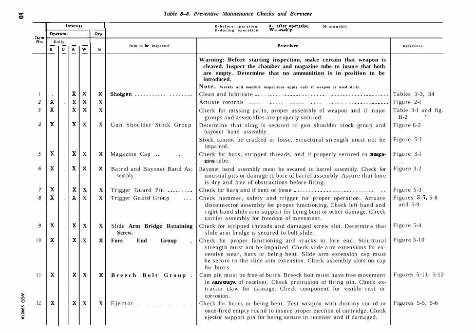
Table f-5. Preventive Maintenance Checks and Servaces
123
4
5
6
78
9
10
11
s 12h:$z
OperatorD a i l y
A-
XXX
X
X
X
XX
X
X
X
X
w-
XXX
X
X
X
XX
X
X
X
X
fOW.
M
XXX
X
X
X
XX
X
X
X
X
l-
Item to be inspected
Gun Shoulder Stock Group
Magazine Cap ~. ~.
Barrel and Bayonet Band As;sembly.
Trigger Guard Pin ~~ ..~~ _~.Trigger Guard Group ._.. . . .
Slide Arm Bridge RetainingScrew.
Fore End Group _
B r e e c h B o l t G r o u p _
Ejector . ..~.....__...__._
B - b e f o r e o p e r a t i o nD - d u r i n g o p e r a t i o n
Aw-2ttgk,ytion M - m o n t h l y
Warning: Before starting inspection, make certain that weapon iscleared. Inspect the chamber and magazine tube to insure that bothare empty. Determine that no ammunition is in position to beintroduced.
Note. Weekly and monthly inspections apply only if weapon is used drily.
Clean and lubricate ..~__....~...____.____--..------___-----..._..Actuate controls _....~~_.....__.________--.._.--_-____.__--....__Check for missing parts, proper assembly of weapon and if major
groups and assemblies are properly secured.Determine that sling is secured to gun shoulder stock group and
bayonet band assembly.Stock cannot be cracked or loose. Structural strength must not be
impaired.Check for burs, stripped threads, and if properly secured to m+ga-
zinc tube.Bayonet band assembly must be secured to barrel assembly. Check for
unusual pits or damage to bore of barrel assembly. Assure that boreis dry and free of obstructions before firing.
Check for burs and if bent or loose _._~~.._____.~__~__ . . . . . . . . ..__.Check hammer, safety and trigger for proper operation. Actuate
disconnector assembly for proper functioning. Check left hand andright hand slide arm support for being bent or other damage. Checkcarrier assembly for freedom of movement.
Check for stripped threads and damaged screw slot. Determine thatslide arm bridge is secured to bolt slide.
Check for proper functioning and cracks in fore end. Structuralstrength must not be impaired. Check slide arm extensions for ex-cessive wear, burs or being bent. Slide arm extension cap mustbe secure to the slide arm extension. Check assembly slots on capfor burrs.
Cam pin must be free of burrs. Breech bolt must have free movementin camways of receiver. Check protrusion of firing pin. Check ex-tractor claw for damage. Check component for visible rust orcorrosion.
Check for burrs or being bent. Test weapon with dummy round oronce-fired empty round to insure proper ejection of cartridge. Checkejector support pin for being secure in receiver and if damaged.
R e f e r e n c e
Tables 3-3, 34Figure 2-lTable 3-l and fig.
B-2 -Figure 6-2
Figure 5-l
Figure 3-lI
Figure 3-2
Figure 5-3Figures 5-7, 5-8
and 5-9
Figure 5-4
Figure 5-10
Figures 5-11, 5-12
Figures 5-5, 5-6

x x1 X Receiver and Magazine Group.. Magazine tube should be secured to the receiver. Check tube for dents, .‘Figure 5-13burrs or damage which will restrict the cartridge. Check helicalcompression spring (magazine) for kinks, and magazine followerfor being broken or burred. Check for rust and corrosion incomponents.

Section V. TROUBLESHOOTING
34. GeneralRefer to table 3-6.
Table $16. Troubleshooting
MalfuIietion
Failure to fire _ _ _
Failure to load or feed
Failure to function correctly
Probable ca”se
Failure to load
E m p t y m a g a z i n e
F a u l t y a m m u n i t i o n _. _ _ _
Foreign matter in firing pin aper-ture of cam pin, bolt or boltslide.
Operator fails to disengage safety.Foreign matter in safety aperture
in trigger.
Failure to move bolt slide fully for-ward.
Dbstruction in the chamber _Defective carrier assembly . _ . . .Foreign matter in RH or LH slide
arm supports or magazine tube.
Foreign matter in bolt, bolt slideor safety well of trigger guard.
I Corrective action.
Note. For corrective action of malfunctions notlisted in this table, refer to direct support~~Ml~kI~l.
Pump shell into chamber.
Load magazine (step 2, fig. 2-2).
Pump out defective shell and useother ammunition.
Clean applicable items (4, 8, or 9, fig.B-4 and table 3-3).
Disengage safety (step 1, fig. 2-3).Clean trigger (16, fig. B-3 and table
3-3).
Push fore end forward (step 3, fig.2-2).
Clean receiver (table 3-3).Notify direct support maintenance.Clean applicable items (2, 3, fig. B-3
and 28, fig. B-2).
Clean applicable items or area (8, 9,fig. B-4 and 18, fig. B-3).
Section VI. MAINTENANCE PROCEDURES
3-7. Removal/Installation of MajorComponents
a. Operator. Field stripping of weapon intomajor groups and assemblies is not authorized.
21. Organizational. Refer to table 3-7.
3-8. Disassembly/Assembly of MajorComponents
a. Operate. None authorized.
b. Organizational. Refer to table 3-7.
Note. White arrows shown on illustrationsdisassembly, black arrows indicate assembly.
12.
indicate
3-9. Cleaning, inspection and Repaira. Clsmin~g instrwtions. Refer to table 3-3.
B. Inspection. Refer to tables 3-6 and 3-7.
c. Repair.
( 1) Replace- bayonet band screws or bay-onet band assembly if damaged or unservice-able.
(2) No other repair parts are authorizedfor organizational maintenance. If necessary,evacuate shotgun to direct support maintenancepersonnel.
AGO ZOW7A
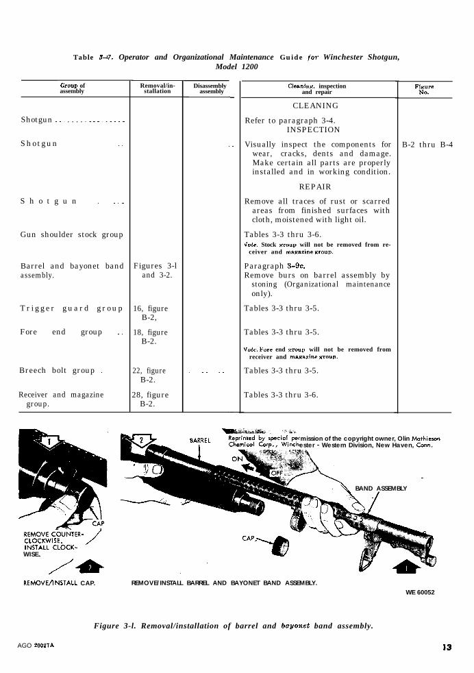
Table 3-17. Operator and Organizational Maintenance Guide fov Winchester Shotgun,Model 1200
Group ofassembly
Shotgun .._ . . . . __..__.___
Shotgun .._ __
S h o t g u n
Gun shoulder stock group
Barrel and bayonet bandassembly.
Tr igger guard group
Fore end group ~.
Breech bolt group _ 22, figureB-2.
Receiver and magazine 28, figuregroup. B-2.
WISE.
REMOVEjlNSTALL CAP.
Removal/in-stallation
Figures 3-land 3-2.
16, figureB-2,
18, figureB-2.
Disassemblyassembly -
_
-
Cleaninrr. inspectionand repair
CLEANING
Refer to paragraph 3-4.INSPECTION
Visually inspect the components forwear, cracks, dents and damage.Make certain all parts are properlyinstalled and in working condition.
REPAIR
Remove all traces of rust or scarredareas from finished surfaces withcloth, moistened with light oil.
Tables 3-3 thru 3-6.Vote. Stock WOUI) will not be removed from re-
ceiver and magazine YIBUP.
Paragraph 3-9c.Remove burs on barrel assembly by
stoning (Organizational maintenanceonly).
Tables 3-3 thru 3-5.
Tables 3-3 thru 3-5.
Vutc. l*‘ore end PROUD will not be removed fromreceiver and maaazine croup.
Tables 3-3 thru 3-5.
Tables 3-3 thru 3-6.
FirC
B-2 thru B-4
mission of the copyright owner, Olin Mathicsonester - Western Division, New Haven, Corm.
BAND ASSEMBLY
REMOVE/INSTALL BARREL AND BAYONET BAND ASSEMBLY.
WE 60052
Figure 3-l. Removal/installation of barrel and ba.yonet band assembly.
AGO 20027A 13

REMOVE/INSTALL SCREWS.
PLASTIC ‘HAMMER
REMOVE BAYONET BAND AS%f+faLY.
INSTALL BAYONET BAND ASSEMBLY. WE 60053
Figure Y-2.Renzoval/installatiOrf of bawnct
band assembly.
14
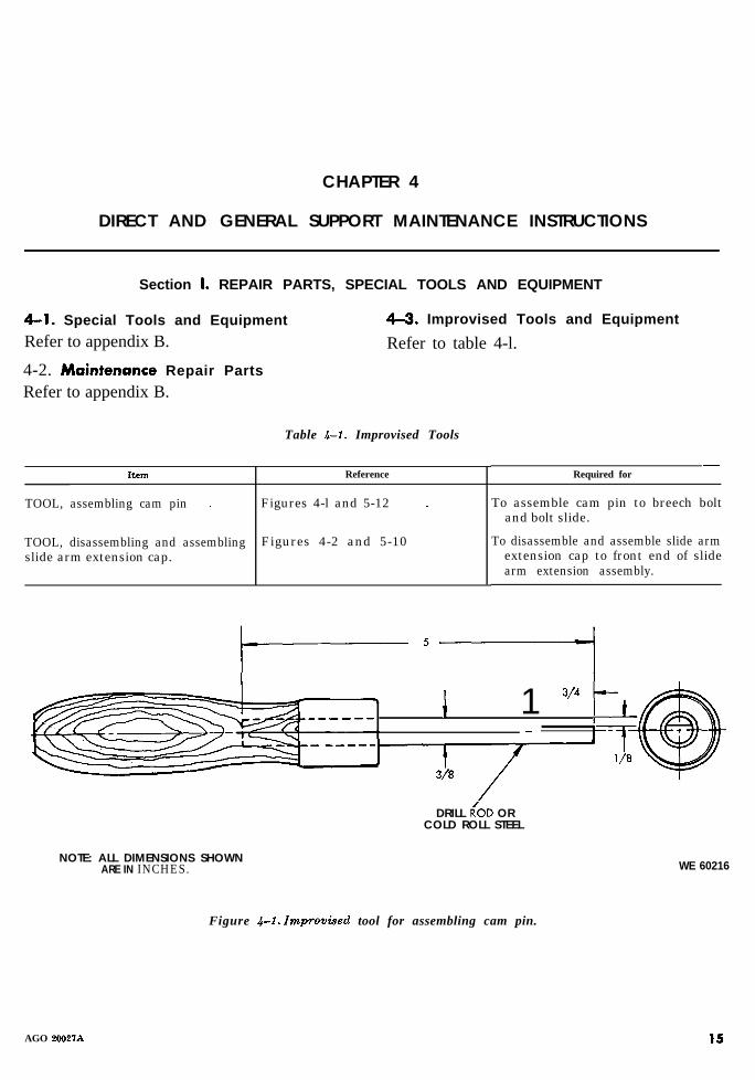
CHAPTER 4
DIRECT AND GENERAL SUPPORT MAINTENANCE INSTRUCTIONS
Section I. REPAIR PARTS, SPECIAL TOOLS AND EQUIPMENT
4-l. Special Tools and Equipment
Refer to appendix B.
4-2. Maintenance Repair Parts
Refer to appendix B.
4-3. Improvised Tools and Equipment
Refer to table 4-l.
Table 4-l. Improvised Tools
Item Reference
TOOL, assembling cam pin ~.
TOOL, disassembling and assemblingslide arm extension cap.
Figures 4-l and 5-12 ~.
Figures 4-2 and 5-10
Required for-
To assemble cam pin to breech boltand bolt slide.
To disassemble and assemble slide armextension cap to front end of slidearm extension assembly.
i 1 3/4 t------- - i-43II^w,- -----1 _
DRILL R/OD ORCOLD ROLL STEEL
NOTE: ALL DIMENSIONS SHOWNARE IN INCHES. WE 60216
Figure 4-f. Improvised tool for assembling cam pin.
AGO 20027A 15

BODY: 6-l/2 LONG BY l/4 THICK COLD ROLL STEEL.BLADE: 1 INCH BY l/8 X l-1/2 TOOL STEEL, FLAT STOCK.RIVETS: 3/16 BY l/2 L O N G .
- I I - -1/8
NOTE: ALL DIMENSIONS SHOWNARE IN INCHES. WE 60215
Figure 4-2. Improvised tool for disassembling and assembling slide arm extension cap.
Section II. TROUBLES,HOOTING
4-4. General and corrective actions for the 12 Gage, Shot-gun, Riot Type, Winchester, Model 1200 are
Troubleshooting malfunctions, probable causes, listed in table 4-2.
Table 4-2. Troubleshooting
Malfunction
Failure to fire
Probable cause
Failure to feed
Short or broken firing pin ~.Foreign matter in firing pin aper-
ture in bolt.Broken hammerBent or damaged helical torsion
spring (hammer).Burred or broken trigger spring
N&u. l’rirrter aw%w is H c o m p o n e n t o fsaw bracket assembly.
Broken sear
Broken triggeiForeign matter in sear notch of
hammer.Burred trigger guard or foreign
mat in safety well.Damaged disconnector assembly or
helical torsion spring (discon-nector).
Corrective action
Repair magazine tube (28, fig. B-2).If unserviceable, turn in weapon forreplacement.
Replace (2, fig. B-4).Zlean aperture in bolt and bolt slide
(8, 9, fig. B-4).Replace (13, fig. B-3).Replace (12, fig. B-3).
Remove burs or replace sear bracketassembly (9, fig. B-3).
Replace sear bracket assembly (9, fig.B-3).
Replace (16, fig. B-3).Glean sear notch on hammer (table
3-3 and 13, fig. B-3).Repair t.rigger guard or clean safety
well (18, fig. B-3 and table 3-3).Replace, 7, 8, fig. B-3).
16AGO 20027A

Table 4-e. Troubleshootirlg-Continued
Malfunction Probable cause
Failure to extract or eject Worn, burred or broken extractorBent or broken helical compression
spring (extractor).Burred or bent ejector
Failure to load or feed Broken or bent carrier assemblyCorroded magazine follower
D a m a g e d m a g a z i n e t u b e _Broken or kinked helical compres-
sion spring (magazine).Foreign matter in magazine tube
D o u b l e feeding _ _. _ ~. _ Burred or broken LH or RH slidearm supports.
Note. Cartridge Stop and cut off are eom-wnents of above items.
Foreign matter under LH and RHslide arm supports.
Failure to function correctly Damaged disconnector assembly _Burs or foreign matter in bolt
slide and bolt.Broken or bent disconnector or heli-
cal torsion spring (disconnector).Burred or bent slide arms
Notr. Slide arms are components of s l idea r m cstenrion rcswmbly.
Broken or burred cam pinWeak or damaged firing pinSafety sticks ~. ’Burred safety _ _. _Damaged hammer housing
Section III. INSPECTION
corrective action
Replace (7, fig. B-4).Replace (6, fig. B-4).
Repair or replace (24, fig. B-2).Replace (4, fig. B-3).Clean (table 3-3) or replace magazine
follower (27, fig. B-2).Turn in weapon for replacement.Replace (26, fig. B-2).
Clean magazine tube (28, fig. B-2).Replace (2, 3, fig. B-3).
Clean (table 3-3) (2, 3, fig. B-3).
Replace (7, fig, B-3).Repair (8, 9, fig. B-4) or clean (table
3-3).Replace (7, 8, fig. B-3).
Repair or replace slide arm extension(21, fig. B-2).
Repair or replace (4, fig. B-4).Replace (2, fig. B-4).Repair (14, fig. B-3).Repair (14, fig. B-3).Replace (17, fig. B-3).
4-5. GeneralRefer to TB 9-1000-247-35.
AGO 20027A

CHAPTER 5
REPAIR INSTRUCTIONS
Section I. GENERAL MAINTENANCE
5-1. GeneralThis section provides instructions on generalmaintenance procedures.
5-2. General Repair Methods
a. Disassembly and Assembly Procedures.
(1) In disassembling the shotgun, removethe major groups and assemblies wheneverpossible. Refer to figure B-2 and paragraphl-3b. Groups and assemblies may be disas-sembled, as necessary, into individual parts.
(2) Complete disassembly of a unit is notalways necessary in order to make a requiredrepair or replacement. Good judgment shouldbe exercised to keep disassembly and assemblyoperations to a minimum.
(3) During assembly, assemblies andgroups should be assembled first, then installedto form a complete unit. Lubricate frictional(sliding) surfaces before assembly.
b. Replacement of Parts.
Section II. MAINTENANCE
S-5. SpecificRefer to table 5- 1.
(1) Parts will be replaced, when unservice-able.
(2) If screws and washer are damaged,they will be replaced.
(3) All springs should be replaced if theyare broken, deformed, fail to function properly,or fail to meet specific requirements.
5-3. Cleaning and lubricationa. Cleaning. Refer to figures 5-14 thru 5-16.
b. Lubrication. Prior to assembly of majorgroups and assemblies, all components will belubricated in accordance with table 3-3.
54. Finished Surfacesa. All metal surfaces subjected to wear and
abrasions and which reflect light or will besubject to rust or erosion, will be treated withblack lacquer.
b. All surfaces must be clean and dry priorto spraying. Allow two hours for lacquer todry.
OF SHOTGUN
18 A G O 2 0 0 2 7 A

M
8
Item
s
G u n s h o u l d e r s t o c k g r o u pMagazine cap ~~. ~.Barrel and bayonet band assemblyT r i g g e r g u a r d g r o u p ~.
Fore end group
Breech bolt group .~~Receiver and magazine group
Table 5-1. Guide to Maintenance Function of Shotgun
Removal/installatiin
Figure 5-l ~.~. __Figure 3 - l%gure3-1 _~.~__...__?igures 5-3 and B-2 _
Figure 5-4 ~~ .~~..~_.~~~.~. .~~b’ote. When barrel and bayonet band assen
bly have been removed do not slam thfore end forward or pull the triage]allowing hammer to fall. This may jazthe action, making necessary the remowof trigger guard end the recocking of thhammer by hand.
Figure 5-4 ._~_. ..~..~.~..
Diussembly/awembly
Iota All pins should be removed from leftto right installed right to left when appli-cable.
Figure B - 2 _.__ _.____.. . . . ..__...
Figure B-2 __________..__ . . . .._...
F i g u r e s 3-2 and 5-2 _. . . _. _. -
Figures 5-7, 5-8, and 5-9 ___.. ----.l&e. To uraemble disconnector spring, turnspring upright so tail of spring is engagedin its proper position in trigger guard pinhole slot. Turn disconnector to uprightposition and slide front of spring underledge on disconnector. Compress front ofdisconnector downward until disconnectorbutton is in line with slot in trigger guard.Hold in this position and push inward untildisconnector pin engages hole in oppositeside of sear bracket and hammer housinrr.
Figure 5-10 ___..___.._ . . . .._._...
Figure 5-11,5-12 _____ ___..~.....
Figures 5-5, 5-6 and 5-13 . . _. _ _Vote. When breech bolt group is removed, the
ejector will fall free of the support pin inthe receiver.
Cleaning, inspection and repair
Refer to figures 5-14 thru 5-16 forcleaning instructions.
Repair (para 5-2)Repair (para 62)Repair (para 5-2)Repair (para 5-2)Vote. If new trigger assembly is installed, it
must be adjusted to fit as follows:
a. With the safety in safe position and.rigger pulled, check the trigger thmugb trig-!er stop pin hole with 0.252040005 diameter,in.
b. With the safety in safe position and trig-rer pulled, adjust trigger adjustment screwNithin 0.003-0.005 of sear. Break off end ofscrew end apply seal ing compound.
Repair (para 5-2)
Repair (para 5-2)
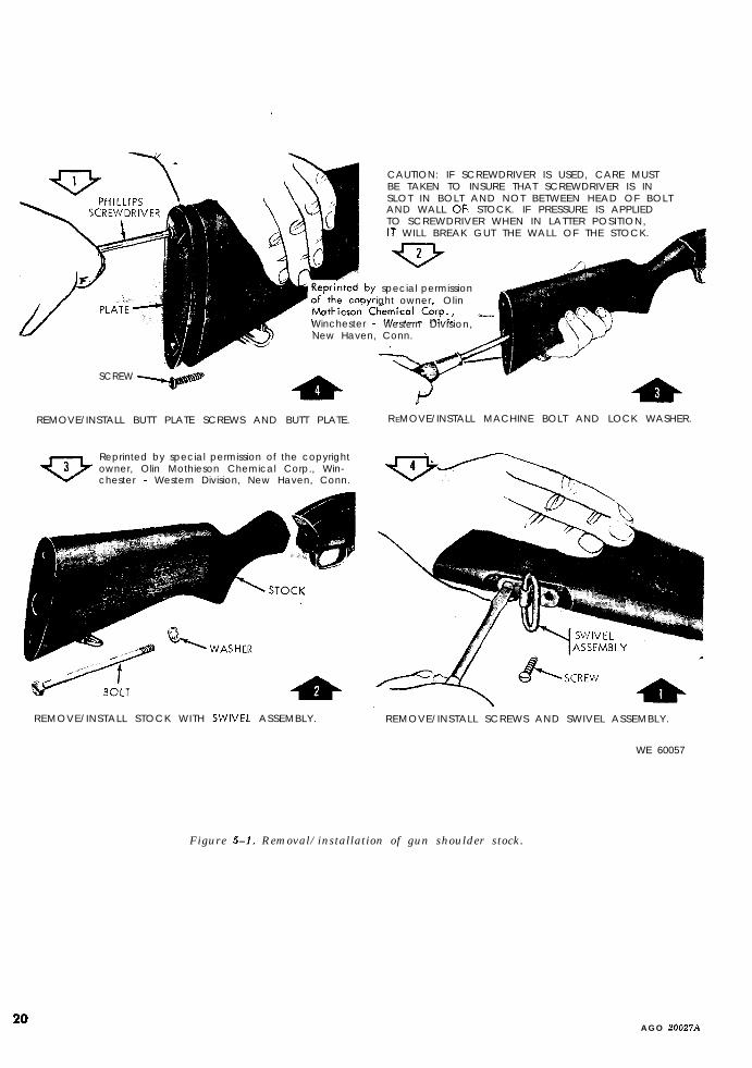
CAUTION: IF SCREWDRIVER IS USED, CARE MUSTBE TAKEN TO INSURE THAT SCREWDRIVER IS INSLOT IN BOLT AND NOT BETWEEN HEAD OF BOLTAND WALL 06 STOCK. IF PRESSURE IS APPLIEDTO SCREWDRIVER WHEN IN LATTER POSITION,IT WILL BREAK GUT THE WALL OF THE STOCK.
special permissionight owner, Olin
Winchester - Western Division, -New Haven, Conn.
SCREW
REMOVE/INSTALL BUTT PLATE SCREWS AND BUTT PLATE.
Reprinted by special permission of the copyrightowner, Olin Mothieson Chemical Corp., Win-chester - Western Division, New Haven, Conn.
REMOVE/INSTALL STOCK WITH SWNEL ASSEMBLY.
R EMOVE/INSTALL MACHINE BOLT AND LOCK WASHER.
REMOVE/INSTALL SCREWS AND SWIVEL ASSEMBLY.
WE 60057
20
Figure 5-l. Removal/installation of gun shoulder stock.
A G O 20027A
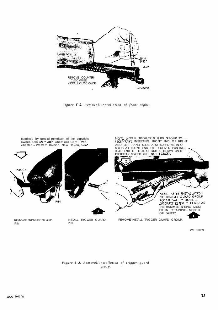
REMOVE COUNTER-CLOCKWISE.
INSTALL CLOCKWISE.
Figure 5-2. Removal/installation of front sight.
Reprinted by special permission of the copyrightowner, Olin Mathieson Chemical Corp., Win-chester - Western Division, New Haven, Corm.
REMOVE TRIGGER GUARDPIN.
NOTE. INSTALL TRIGGER GUARD GROUP TOPFCFIGFR RY INSERTING FRONT FND OF RIGHT. _. _ _,.C__. _.. _
AND LEFT HAND SLIDE ARM SUPPORTS INTOSLOTS AT FRONT END OF RECEIVER PUSHINGREAR END OF GUARD GROUP DOWN UNTILPROPERLY SEATED (DO NOT FORCE).
INSTALL TRIGGER GUARDPIN.
-._.,,. -.__._THE HAMMER SPRING MUSTFIT IN RETAINING NOTCHOF SAFETY.
REMOVE/INSTALL TRIGGER GUARD GROUP.-dr
WE 50059
AGO 20027A
Figure 5-3. Removal/installation of trigger guardgroup.
21
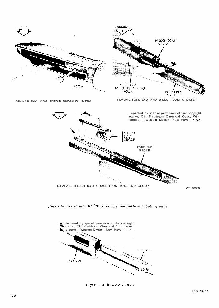
REMOVE SLID’ ARM BRIDGE RETAINING SCREW. REMOVE FORE END AND BREECH BOLT GROUPS.
Reprinted by special permission of the copyrightowner, Olin Mathieson Chemical Corp., Win-chester - Western Division, New Haven, Corm.
FORE ENDGROUP
SEPARATE BREECH BOLT GROUP FROM FORE END GROUP.WE 60060
Figure T-4. Removal/insta~lation of fore evd and b,cech bolt groups.
Reprinted by special permission of the copyrightowner, Olin Mathieson Chemical Corp., Win-chester - Western Division, New Haven, Cow.
Figarc 5-5. RC~OUC e.iccto)..
AGO 20027A
Reprinted by special permission of. the copyrightowner, Olin Mathieson Chemical Corp., Win-chester - Western Division, New Haven, Corm.
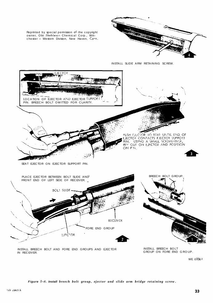
INSTALL SLIDE ARM RETAINING SCREW.
LOCATION OF EJECTOR AND EJECTOR SUPPORPIN. BREECH BOLT OMITTED FOR CLARITY. -_- -
SEAT EJECTOR ON EJECTOR SUPPORT PIN.
PLACE EJECTOR BETWEEN BOLT SLIDE AND
‘\FRONT END OF LEFT SIDE OF RECEIVER.
\$
FORE END GROUP
INSTALL BREECH BOLT AND FORE END GROUPS AND EJECTORIN RECEIVER.
BREECH BOLT GROUP.
INSTALL BREECH BOLTGROUP ON FORE END GROUP.
WE 60051
Figure 5-6. Install breech bolt group, ejector and slide arm bridge retaining screw.
23
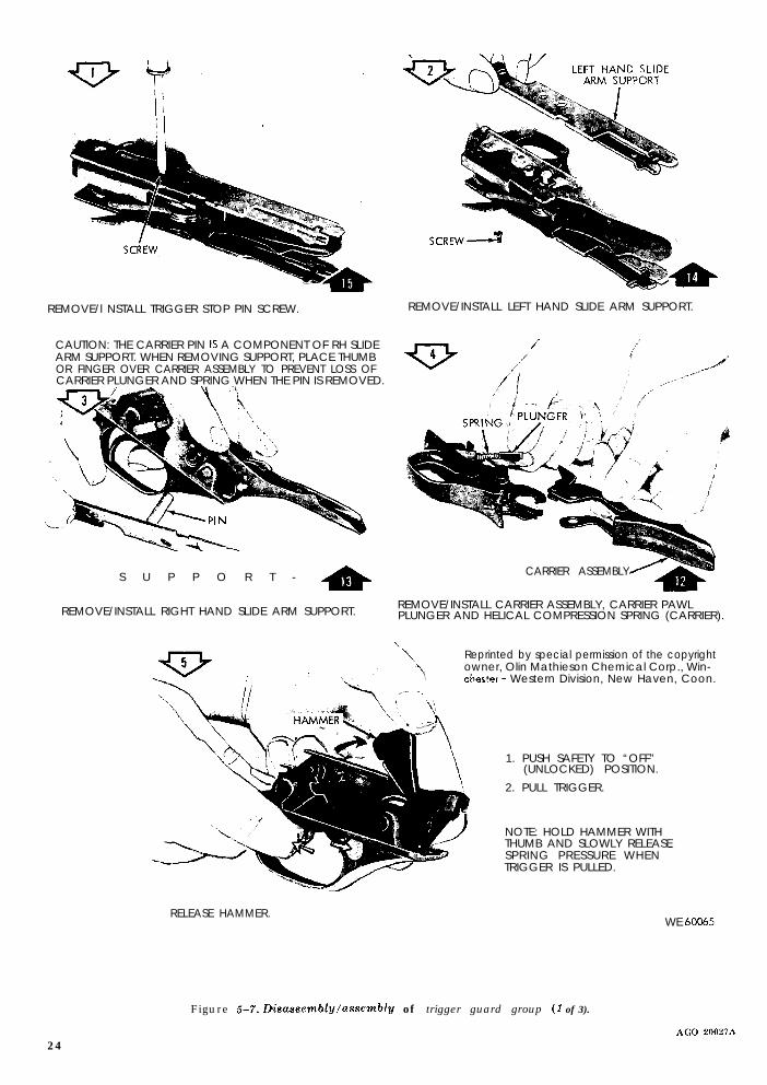
REMOVE/l NSTALL TRIGGER STOP PIN SCREW. REMOVE/INSTALL LEFT HAND SLIDE ARM SUPPORT.
CAUTION: THE CARRIER PIN IS A COMPONENT OF RH SLIDEARM SUPPORT. WHEN REMOVING SUPPORT, PLACE THUMBOR FINGER OVER CARRIER ASSEMBLY TO PREVENT LOSS OFCARRIER PLUNGER AND SPRING WHEN THE PIN IS REMOVED.
S U P P O R T - *
REMOVE/INSTALL RIGHT HAND SLIDE ARM SUPPORT.
CARRIER ASSEMBLY
REMOVE/INSTALL CARRIER ASSEMBLY, CARRIER PAWLPLUNGER AND HELICAL COMPRESSION SPRING (CARRIER).
\
\Reprinted by special permission of the copyrightowner, Olin Mathieson Chemical Corp., Win-
\ Chester - Western Division, New Haven, Coon.,,c--.
NOTE: HOLD HAMMER WITHTHUMB AND SLOWLY RELEASESPRING PRESSURE WHEN -TRIGGER IS PULLED.
RELEASE HAMMER.
1. PUSH SAFETY TO “OFF”(UNLOCKED) POSITION.
2. PULL TRIGGER.
WE 60065
Figure 5-7. LXsassembly/asscmbly of trigger guard group (1 of 3).
24AGO 20027A
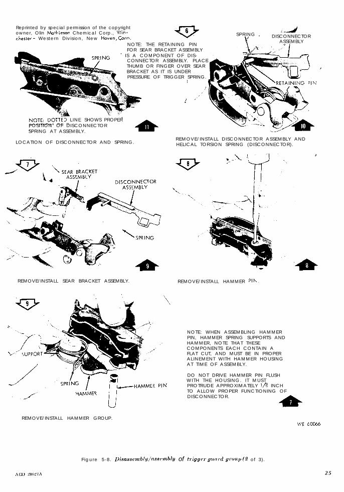
Reprinted by special permission of the copyrightowner, Olin Mathieson Chemical Corp., Win-Chester - Western Division, New Haven, Corm.
NOTE: THE RETAINING PINFOR SEAR BRACKET ASSEMBLY
’ IS A COMPONENT OF DIS-CONNECTOR ASSEMBLY. PLACETHUMB OR FINGER OVER SEARBRACKET AS IT IS UNDERPRESSURE OF TRIGGER SPRING.
I
,//’
i ,,’
SPRING __._4+
DISCONNECTORASSEMBLY
I
L INE SHOWS PROPERPOSITION OF DISCONNECTORSPRING AT ASSEMBLY.
LOCATION OF DISCONNECTOR AND SPRING.REMOVE/INSTALL DISCONNECTOR ASSEMBLY ANDHELICAL TORSION SPRING (DISCONNECTOR).
REMOVE/INSTALL SEAR BRACKET ASSEMBLY. REMOVE/INSTALL HAMMER PIN.
REMOVE/INSTALL HAMMER GROUP.
NOTE: WHEN ASSEMBLING HAMMERPIN, HAMMER SPRING SUPPORTS ANDHAMMER, NOTE THAT THESECOMPONENTS EACH CONTAIN AFLAT CUT, AND MUST BE IN PROPERALINEMENT WITH HAMMER HOUSINGAT TIME OF ASSEMBLY.
DO NOT DRIVE HAMMER PIN FLUSHWITH THE HOUSING. I T MUSTPROTRUDE APPROXIMATELY l/R INCHTO ALLOW PROPER FUNCTIONING OFDISCONNECTOR.
F igure 5-8. Disassembl?J/nssemblU of tliggw gunwl g,‘oup (2 of 3).
25
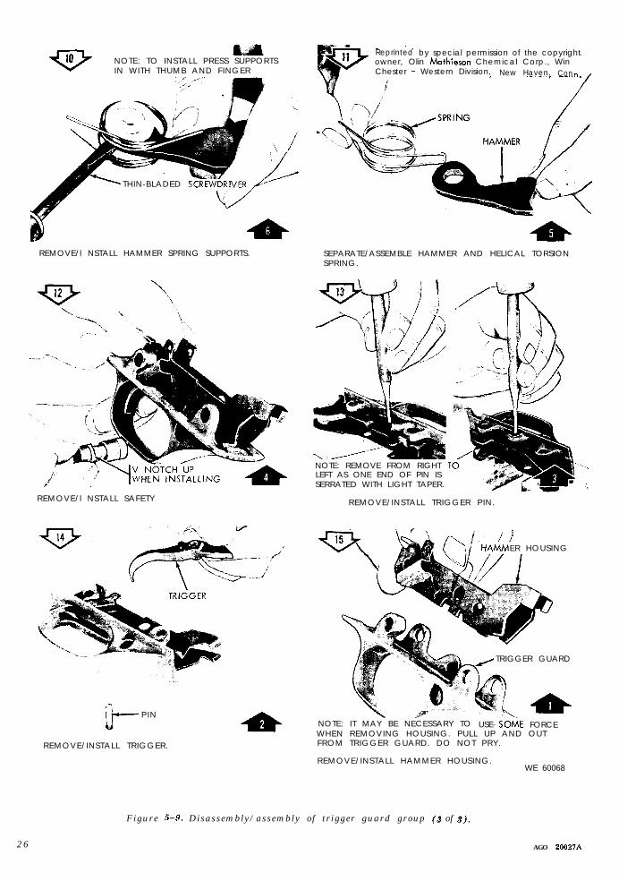
NOTE: TO INSTALL PRESS SUPPORTSIN WITH THUMB AND FINGER
THIN-BLADED
REMOVE/l NSTALL HAMMER SPRING SUPPORTS.
REMOVE/l NSTALL SAFETY
“Ib-- PIN
REMOVE/INSTALL TRIGGER.
Reprinted by special permission of the copyrightowner, Olin Mathieson Chemical Corp., WinChester - Western Division, New Haven, Con
SEPARATE/ASSEMBLE HAMMER AND HELICAL TORSIONSPRING.
NOTE: REMOVE FROM RIGHT 1LEFT AS ONE END OF PIN ISSERRATED WITH LIGHT TAPER.
REMOVE/INSTALL TRIGGER PIN.
ER HOUSING
TRIGGER GUARD
NOTE: IT MAY BE NECESSARY TO USE- SOtiE FORCEWHEN REMOVING HOUSING. PULL UP AND OUTFROM TRIGGER GUARD. DO NOT PRY.
REMOVE/INSTALL HAMMER HOUSING.WE 60068
2 6
Figure 5-9. Disassembly/assembly of trigger guard group (3 of 9).
AGO 20021A

Reprinted by special permission of the copyrightowner, Olin Mothieson Chemical Corp., Win-
r - Western Division, New Haven, Corm.
DISASSEMBLY/ASSEMBLY
REMOVE/INSTALL SLIDE ARM CAP. REMOVE/INSTALL FORE END.
WE 60062
Figure 5-10. Disassembly/assembly of jo,re end group.
27
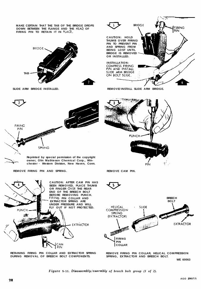
MAKE CERTAIN THAT THE TAB OF THE BRIDGE DROPSDOWN BETWEEN THE FLANGE AND THE HEAD OFFIRING PIN TO RETAIN IT IN PLACk.
TAB
SLIDE ARM BRIDGE INSTALLED.
Reprinted by special permission of the copyrightowner, Olin Mathieson Chemical Corp., Win-chester - Western Division, New Haven, Conn.
REMOVE FIRING PIN AND SPRING.
CAUTION: AFTER CAM PIN HAS\ BEEN REMOVED. PLACE THUMB
OR FINGER OVkR THE REAREND OF THE BREECH BOLTBEFORE REMOVING PUNCH.FIRIN G PIN COLLAR AND
s EXTRACTOR SPRING AREUNDER PRESSURE AND WILLFLY OUT IF NOT PROTECTED.
&EXTRkCTOR
RETAINING FIRING PIN COLLAR AND EXTRACTOR SPRINGDURING REMOVAL OF BREECH BOLT COMPONENTS.
CAUTION: HOLDTHUMB OVER FIRINGPIN TO PREVENT PINAND SPRING FROMBEING LOST UNTILBRIDGE IS REMOVEDOR INSTALLED.
INSTALLATION:
REMOVE/INSTALL SLIDE ARM BRIDGE.
PIN .“_’
REMOVE CAM PIN.
BREECHBOLT
FIRINGPINCOLLAR
REMOVE FIRING PIN COLLAR, HELICAL COMPRESSIONSPRING, EXTRACTOR AND BREECH BOLT.
WE 60063
Figure 5-11. Diaassembl~/asscmbly of breech bolt group (1 of 2).
28 AGO 20021.4

INSTALL HELICAL COMPRESSIONSPRING ON FIRING PIN. INSERTSPRING AND PIN IN BREECH BOLTFROM REAR, MAKING CERTAINTHAT FIRING PIN PASSES THRU
-HOLE IN CAM PIN. COMPRESSFIRING PIN. \
INSTALL FIRING PIN AND HELICAL COMPRESSIONSPRING (FIRING PIN).
NOTE: ALINE CAM SLOT WITH CAM PIN HOLE IN THEBOLT BY LIFTING BOLT SLIDE SLIGHTLY. START END OFCAM PIN NEAREST FIRING PIN HOLE INTO THE BOLT.THE HOLE IN CAM PIN MUST BE IN LINE WITH THE LONGAXIS OF BOLT. USING DRIFT PIN OR (IMPROVISED) CAMPIN ASSEMBLY TOOL, PUSH FIRING PIN COLLAR DOWNTO COMPRESS THE HELICAL COMPRESSION SPRING.
CAUTION: DO NOT HAVE YOUR FACE IN LINE WITHBACK END OF BOLT DURING THIS OPERATION. PUSHCAM PIN IN AS FAR AS IT WILL GO. AT THIS POINTCOLLAR MAY PREVENT PIN FROM SEATING FULLY. IFNECESSARY, USE A SMALL ROD OR SCREWDRIVER TODEPRESS THE UPPER EDGE OF COLLAR WHILE SEATINGCAM PIN.BOLT SHOULD BE BOTTOM SIDE UP WITH EXTRACTOR ONRIGHT HAND SIDE. LOOKING THRU BOLT FROM REAR,CLEAR PASSAGE FOR FIRING PIN SHOULD BE VISIBLE.
Reprinted by special permission of the copyrightowner, O’in Mothieson Chemical Corp., Win-chester - Western Division, New Haven, Corm.
INSTALL BREECH BOLT.
EXTRACTOR
INSTALL EXTRACTOR,
SEAT CAM PIN.
CAM PINASSEMBLY
INSTALL CAM PIN.
BREECH BOLT
Figzwe 5-M Disaeeembly/assembl~ of breech bolt group (2
SPRING AND COLLAR.
of 2).
29

CAUTION: WHEN REMOVING \
MAGAZINE SPRING FROM
-.\
PLUG
\ “? I/REMOVE MAGAZINE PLUG. INSTALL MAGAZINE PLUG.
MAGAZINE
Reprinted by special permission of the copyright owner, Olin MothiesonChemical Corp., Winchester - Western Division, .N Haven, Corm .
1
tE
NOTE: DO NOT ATTEMPT TO REMOVEMAGAZINE FROM RECEIVER AS THISIS A FACTORY ASSEMBLY OPERATIONONLY.
PLUG
R E M O V E/ INSTALL PLUG AND H E L IC AL COMPRESSION SP R I NG (M AG A Z I N E) .
3 0
FOLLOWER ,,
REMOVE
6
REMOVE/INSTALL MAGAZINE FOLLOWER.
Figure 5-13. Disasscmbl~/assembl~ o f mccgazitle.
WE 60069
XGO 20027A
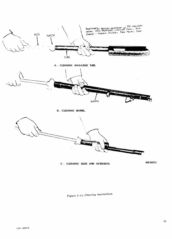
Reprinted by special permission of the copyright
A - CLEANING MAGAZINE TUBE.
B - CLEANING BARREL.
C - CLEANING SLIDE ARM EXTENSION. WE 60071
31
,\c,o ?n027A

BRUSH IRECEIVER
A _ LUBRICATING RECEIVER AND MAGAZINE TUBE*
B _ LUBRICATING SLIDE ARM EXTENSION.
\
‘> >BAND
ASSEMBLY
C _ L(,BR\CAT]NG BARREL AND BAYONET BAND ASSEMBLY.h
,
..^ .tIGGER GUAKU Vnuu’- WE 60070E - LU BRICATING Tr
rnr\,,D*
_^^,,n
D _ LUBRICATING BREEC:H BOLT GKUur.
Figure 5-I 5.Lubricating instructic”s* Aa 20021
32

NOTE: RURUNSEEDOIL IN WOOD TOTREAT STOCK.
A. STOCK WITH SWIVEL ASSEMBLY. B. FORE END.
WE 60072
Figure 5-16. Cleuniug and treating wooden components.
5-6. Functioning with Once-Fired Empty will be handfunctioned, using five once-fired
Rounds empty rounds. Shotguns which fail in above-noted test will be corrected by replacement of
Shotguns authorized to be repaired in the field defective parts.
33

CHAPTER 6
MATERIAL USED IN CONJUNCTION WITH MAJOR ITEM
6- 1. GeneralThis chapter contains information on materielused with the major item.
6-2. Descriptiona. Bayonet, Ml91 7’. (fig. B-l) It is used for
close contact, guarding of prisoners and riotduty. It can also be used as a general utilityknife. It has a cutting edge of 14.81 inches atthe bottom running from the point. The handlefits comfortably and has a knurled surface fora firm grip.
b. Sling, Ml. (fig. B-l) It hooks on the gunshoulder stock swivel and adapter swivel ofbayonet band assembly and aids the operatorin carrying and firing the weapon.
c. ScaBbard, Bayonet, M1.917. (fig. B-l) It isused to carry the bayonet Ml917 when notbeing used on the shotgun.
6-3. Removal/Installation
a. Buyovet, M1917. Refer to figure 6-l.
b. Sling, Ml. Refer to figure 6-2.
Figure F-l . Remove/install bayonet, B1917.
6 - 4 . Disa&embly/Assembly 6-5. Cleaning, Inspection and Repair
None authorized. a. Cleaning.
34AGO 200279

-./STEP I. REMOVE SLING FROMy.J SWIVEL ON BAYONET BAND
_JASSEMBLY.
STEP 2. REMOVE SLING FROMSTOCK SWIVEL ASSEMBLY.
TO INSTALL: REVERSE PROCEDURE.
WE 60075
Figure 6-2. Remove/install sling.
(1) Bayonet M1917. Remove grease, oil,and dirt with carbon removing compound (P-C-111). Lubricate with general purpose lubri-cating oil (PL special).
(2) Sling, ,441. Clean with dry cleaningsolvent (SD), using cloth or bristle brush.
(3) Scabba(rd, Ml917. Clean metal partswith carbon removing compound.’ The samecompound can be used to clean plastic com-
ponents if required. Lubricate with generalpurpose lubricating oil.
b. Irspection.
(1) Bayonet, M1917.(a) Should fit shotgun properly and
latch securely.(b) If blade tip or grips are broken,
replace.(c) Blade should be free of nicks,
turned edges, rust and corrosion.
(2) Sling, .Ml.(a) Inspect for required components
such as hooks, fasteners, etc.(b) Check for cuts or other damage
which will reduce strength or protectivequalities.
(c) Examine corners, seams and edgesclosely.
(3) Scabb~ard, Bayonet, M1917.(a) Metal parts should be dark. Re-
paint if required).(b) Spring should hold bayonet when
inserted in scabbard.(c) Loops or hooks for attaching to belt
should not be damaged. They will be securelyfastened to the metal top plate.
c. Repair. Replace bayonet, M1917, Sling,Ml, Scabbard, Bayonet, Ml917 or cleaning rod(wooden) if unserviceable.
35