wind interconnection in new england - renew...
TRANSCRIPT

S E P T E M B E R 3 0 , 2 0 1 4 | H O L Y O K E , M A
Wind Interconnection in New England
ISO/RENEW Meeting

Agenda
1. Welcome and Introductions
2. ISO-NE Overview of New England Power System as it Relates to Wind Interconnection
3. Interconnection Study Timelines, Budget, and Staffing
4. Minimum Interconnection Standard and Curtailment Risk
5. Modifications to Attachment A and B (Interconnection Study Request Data), Interconnection Agreement
6. Material Modification Manual
7. Detailed Voltage Studies within Wind Farm Driving Use of Detailed Models
2

Agenda, cont.
8. Should ISO Operating Criteria of Zero Turbine Trips After Normal Contingencies be Relaxed?
9. Electronic Data Submittal System
10. Communications
11. New NERC Reporting Requirements
3

AGENDA ITEM 2: ISO-NE OVERVIEW OF NEW ENGLAND POWER SYSTEM AS IT RELATES TO WIND INTERCONNECTION

Generator Interconnection Technical Challenges
• Development Behind Transmission Constraints
• Nature of the Interconnection
• Implications of Generator Technology
• Consequences for System Operations
5

Generation Development Behind Transmission Constraints
• All generators in New England compete for transmission use in the Energy Market based on bid price – A completed interconnection study, meeting overlapping impact requirements
in the Forward Capacity Market, and Large/Small Generator Interconnection Agreement (L/SGIA) do NOT assure that a resource can always produce energy
– Definite risk of curtailment, even without transmission outages – Areas of the system where new renewable resources compete with thermal
resources and existing renewable resources, sometimes the same owner
• Regional transmission constraints – Broader areas of the system which may constrain concurrent operation of
larger groups of generation. Regional constraints may be in series or nested.
• Local transmission constraints – Smaller areas of the system which may constrain concurrent operation of
smaller groups of generation. May be nested behind other constraints, particularly regional constraints.
– Many wind curtailments due to local constraints
6

Nature of the Generator Interconnection
• Any generator located very far from its interconnection to the transmission system is likely subject to voltage and stability performance issues
• Any generator interconnecting to a portion of the transmission system with long and lower voltage facilities is likely subject to voltage and stability performance issues
• Many generators are connecting into electrically weak parts of the New England system and Eastern Interconnection – 50 miles of 115 kV line roughly equivalent to 450 miles of 345 kV line
• Wind interconnecting with bare minimum voltage support – no margin – Per FERC Order 661, wind plants are required to provide .95 power factor to support
voltage control only if the SIS shows that it is required for reliability
• First-in generators, especially wind, have quickly utilized any limited existing system margins, resulting in more significant system upgrades for subsequent generators
7

Implications of Generator Technology
• Synchronous generators can provide voltage and inertial support at their Point of Interconnection (POI)
• Inverter-based generators typically have not provided significant system voltage or stability support, although technologies are improving
• Voltage control/reactive power capability of wind generators, where available, is mostly consumed within the wind farm; little remains for overall system support
• Some wind generator power electronic controls will not function properly in weak areas
• Frequent performance issues and adjustments to stability models for some wind generator and plant voltage control models throughout study and post study period
8

Consequences for System Operations
• System Impact Study is a discrete testing program – Does not directly capture full range of real-time load, outages and needs of
system operators to manage the system and operate under a broad range of conditions
• Interconnections planned with little or no operating margin (pursuant to FERC Order 661) can and will result in significant plant operating restrictions – Normal operating conditions remove facilities from service, inherently
weakening the system • Wind plants interconnection plans can become immediately insufficient, relative to
the operating condition
– Greatly impacted by line-out conditions – Actual operating conditions can be much more stressed than in studies – Limited margin in study conditions results in greater risk of constraints in
normal operation – Wind farm curtailment very dependent changing system conditions
9

Consequences for System Operations, cont.
• Each plant design is unique; problems mitigated using multiple devices – Creates a great challenge to practical system operation – Impractical for System Operators to be able to understand all of the unique features of
each installation – Far too many operating condition permutations – This is a growing concern as more facilities are added to the system
• Last-minute modeling and information changes can result in – Delays to commercial operation – Output limitations
• These issues with wind farms have resulted in significant complications for system operations – For example, the addition of complicated operating interfaces
10

New England CT MA ME NH RI VT
NR Capacity (MW) 707.7 0.0 43.5 384 .0 166.5 0.0 113.7
Num of Wind Farms in this overview
15 0 2 7 3 0 3
Existing Wind Capacity Overview
11
Capacity by Type
Type III 77%
Type IV 23%
Capacity by Manufacturer
Vestas 46%
GE 28%
Gamesa 13%
Siemens 7%
Clipper WP Liberty 6%
• NR Capacity: Network Resource Capacity
• The percentage calculation was based on NR Capacity

Existing Wind Farms (Maine)
Spruce Mt 20 MW
Record Hill 50.6 MW
Saddleback 34.2 MW
Canton Mt 22.8 MW
Kibby 132 MW
Bull Hill 34.2 MW
Rollins 82.5 MW
Stetson 60 MW
Keene Road Export
Orrington Import
Orrington South
Wyman Hydro
Export
Rumford
Area
Export
Surowiec
South
Note: The MW value of each wind farm is its nameplate capacity. 12

Existing Wind Farms (NH, VT, MA)
Kingdom 64.58 MW
Sheffield 40.00 MW
Granite 99.00 MW
Groton 48.00 MW
Lempster 24.00 MW
Hoosac 28.50 MW
Sheffield +
Highgate
Export
Whitefield
South +
GRPW
East-West
ME- NH
Note: The MW value of each wind farm is its nameplate capacity. 13

The Problem of Electrical Distance
• The transfer of power over long distances using limited transmission infrastructure results in voltage concerns – These voltage concerns can be illustrated and investigated using
concepts such as: • Surge Impedance Loading (SIL) • PV (Power vs. Voltage) Analysis • QV (Reactive Power vs. Voltage) Analysis • Short Circuit Ratio (SCR)
14

Surge Impedance Loading
• The MW loading of the line at which a natural reactive power balance occurs – When a line is loaded above its SIL, it acts like a shunt reactor,
absorbing reactive power from the system – When a line is loaded below its SIL, it acts like a shunt capacitor,
supplying reactive power to the system
15

Reactive Power and Voltage Analysis: SIL
• VAR Losses and Surge Impedance Loading Analysis
St. Clair curve:
50 miles: the line limit is dependent on the thermal limit
50 miles to 200 miles: the line limit is dependent on the voltage drop
200 miles: the line limit is dependent on the small signal stability
16

Reactive Power and Voltage Analysis: Case Study
• Existing 99 MW wind farm, connected to the New England system through two 115 kV lines
• SIL – Post-contingency, the SIL of the remaining 115 kV line is 36 MW
– Wind Farm’s rated real power output is 2.75 times this SIL
• VAR Losses
– In the all-lines-in case, Wind Farm’s rated real power introduced about 23 MVAR of system incremental reactive losses. With one 115 kV line out, the incremental reactive losses increased to 57 MVAR.
– The net VAR loss inside the Wind Farm was about 31 MVAR
– Total reactive losses of 88 MVAR due to the wind farm
17

Reactive Power and Voltage Analysis: PV Analysis
• PV Analysis – Evaluate Voltage Stability
Voltage depression typically starts from inside the wind farm after the incremental real power transfer exhausts all the available reactive resources. Wind interconnection has different voltage collapse behavior from load center due to Low Voltage Ride-through (LVRT) characters.
18

Reactive Power and Voltage Analysis: Case Study
• In PV analysis, without reactive upgrades, Wind Farm encounters voltage collapse when approaching its maximum output
19
0.86
0.91
0.96
1.01
1.06
0 5 10 15 20 25 30 35 40 45 50 55 60 65 70 75 80 85 90 95 100 105 110 115
Vo
lt @
11
5kV
(p
u)
115 kV PV Curves (no reactive output at Wind Farm)
Wind Farm Output (MW)
All Lines In
Post Contingency

Reactive Power and Voltage Analysis: Case Study
• With reactive upgrades, PV performance is improved
20
0.90
0.92
0.94
0.96
0.98
1.00
1.02
1.04
1.06
0
10
20
30
40
50
60
70
80
90
10
0
11
0
12
0
13
0
14
0
14
2
Vo
lt @
11
5kV
(p
u)
Wind Farm 115 kV P-V Curves (with reactive upgrades)
Wind Farm Output (MW)
All Lines In
Post Contingency

Consequences for System Operation
• With the reactive upgrades installed in the field, the system barely maintains voltage stability – This tight margin indicates more output restrictions on the wind farm
when the local system has a facility out for maintenance or other impaired conditions in operations
21

Reactive Power and Voltage Analysis: QV Analysis
• QV Analysis is used to identify reactive margin and mitigation
22
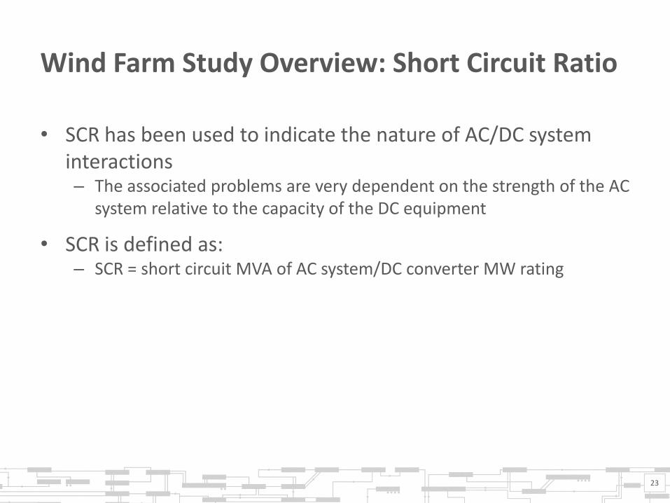
Wind Farm Study Overview: Short Circuit Ratio
• SCR has been used to indicate the nature of AC/DC system interactions – The associated problems are very dependent on the strength of the AC
system relative to the capacity of the DC equipment
• SCR is defined as: – SCR = short circuit MVA of AC system/DC converter MW rating
23

Wind Farm Study Overview: Short Circuit Ratio
• There is no well-defined boundary for SCR distinguishing weak and strong systems, but it is common to consider a system “weak” if SCR is below 2.5
• In a “weak” system, the following problems can be associated with wind interconnections: – Steady state voltage violation – Voltage instability – Oscillation in time domain stability simulation – Wind Turbine Generator (WTG) convertor operation instability
• PSS/E models provided by manufacturers do not represent actual performance under low short circuit conditions – Decreasing confidence in the models
• Decreasing confidence in the ability of turbines to operate reliably in these weak conditions
24

Existing Wind Farms (Maine)
Spruce Mt 20 MW
Record Hill 50.6 MW
Saddleback 34.2 MW
Canton Mt 22.8 MW
Kibby 132 MW
Bull Hill 34.2 MW
Rollins 82.5 MW
Stetson 60 MW
Keene Road Export
Orrington Import
Orrington South
Upper
Kennebec
Hydro Export
Rumford
Area
Export
Surowiec
South
In Farm: 7 MVAR Sys Inc: 6 MVAR Qmax*: 11 MVAR SIL**:32+32MW SCR***: 7.78
* Qmax: the maximum reactive power output of the wind farm including associate reactive devices. ** SIL: the Surge Impedance Loading of the interconnection ***SCR: Short Circuit Ratio at the Point of Interconnection Sys Inc – The Incremental VAR losses on the system resulting from the wind farm
Note: The red MW value of each wind farm is its nameplate
capacity.
In Farms: 18+18 MVAR Sys Inc: 26 MVAR Qmax*: 69 MVAR SIL**:39(R)/33(S) MW SCR***: 8.5(R)/4.5(S)
In Farm: 36 MVAR Sys Inc: 100MVAR Qmax*: 45 MVAR Wyman: 36 MVAR SIL**:36.5MW(3.65) SCR***: 1.76
In Farm: 17 MVAR Sys Inc: negligible Qmax*: 27 MVAR SIL**: 36+36 MW SCR***: 2.74
In Farm: 10MVAR Sys Inc: 30 MVAR Qmax*: 24 MVAR SIL**: 39 MW SCR***: 3.55
In Farm: negligible Sys Inc: 3.45 MVAR Qmax*: 6.5 MVAR SIL**: 4 MW SCR***: 4.04
Spruce Mt Unity pf
@ WTG
terminal
Ctrl 115kV
Voltage
Saddleback Canton Mt
Unity pf @ WTG terminal
Ctrl 115kV Voltage
Ctrl 115kV
Voltage
Ctrl 115kV
Voltage
Stetson Ctrl 115kV
Voltage ±8 DVAR 3.5+3.5+3.0 Caps LTC ctrl 34.5kV
Wyman:2 x 18 Caps
LTC ctrl 34.5kV
25

Existing Wind Farms (NH VT MA)
` Sheffield
40.00 MW
Granite 99.00 MW
Groton 48.00 MW
Lempster 24.00 MW
Hoosac 28.50 MW
Kingdom 64.58 MW
Whitefield
South +
GRPW
East-West
ME- NH
In Farms: 31 MVAR Sys Inc: 57 MVAR Qmax*: 43 MVAR SIL**:36 MW SCR***: 2.57
In Farms: 9 MVAR Sys Inc: negligible Qmax*: 35 MVAR SIL**:34 MW SCR***: 11.03
Sheffield +
Highgate
Export
In Farms: 14 MVAR Sys Inc: 36 MVAR Qmax*: 31+38(Jay) MVAR SIL**:6.9 MW SCR***: 2.29
In Farms: 2 MVAR Sys Inc: negligible Qmax*: 0 SIL**:4 MW SCR***: 4.42
In Farms: 7 MVAR Sys Inc: 7 MVAR Qmax*: 12 MVAR SIL**:14 MW SCR***: 8.27
In Farms: 7 MVAR Sys Inc: 18 MVAR Qmax*: 10 MVAR SIL**:36 MW SCR***: 5.42
Ctrl 115kV Jay Voltage
Unity pf @ 115kV Bus(manually)
Ctrl 115kV
Voltage
Ctrl 115kV
Voltage
Ctrl 34.5kV
Voltage Ctrl
69kV
Voltage
±4 DVAR 4*4.8 Caps
2*±4 DVAR 2*2.5 Caps
Jay Tap: +27.5 -14 Condenser 4*5.4 Caps LTC ctrl 34.5kV
* Qmax: the maximum reactive power output of the wind farm including associate reactive devices. ** SIL: the Surge Impedance Loading of the interconnection ***SCR: Short Circuit Ratio at the Point of Interconnection
Note: The red MW value of each wind farm is its nameplate
capacity.
26

AGENDA ITEM 3: INTERCONNECTION STUDY TIMELINES, BUDGET, AND STAFFING Discussion

Improvements Since Last Workshop
• ISO added new on-site study consultant
• ISO is working with existing study consultants to expedite study schedules
• ISO is providing advance notice of projected approximate start dates for projects that have been on hold due to interdependencies with other projects – Provides project developers an opportunity to verify/refine submitted
data
• Some project developers are refining their projects while they are on hold, using this time effectively
28

Wind Interconnection in Weak Areas Presents Significant and Time-Consuming Study Technical Challenges
• Validation/refinement/replacement of plant models – Improper function of initially provided models
– Electromagnetic transient analysis required for model validation - PSCAD
– Restudies caused by mid-study model malfunction
• Detailed voltage analysis inside the wind farm
• Resolution of wind turbine control mode oscillation (AGO oscillation)
• Complexity of plant operational control
• Concurrent steady state voltage, voltage stability, rotor angle stability and inter-area oscillation constraints
• Interaction of local and inter-area transfers
• Limited reactive support by plant of network issues related to plant
• Reactive resource coordination control design
• Electromagnetic transient analysis of power electronic control interactions
• Each incremental plant further stresses the system, increasing study complexity
29
AGO – Advanced Grid Option

Individual Project Developers Can Be Responsible for Both Individual and Cumulative Project Delays
• Proposals for plants that are overly large for their electrical location – Problems getting the basic plant to function – Challenges addressing the resultant system issues
• Insufficient initial consideration of wind farm design
• Reiterative modification of plant characteristics
• Multiple requests to change equipment manufacturer
• Poorly functioning and/or poorly documented models
• Poor consistency of model performance when comparing PSS/E with PSCAD
• Updates to equipment models for proposed projects
• Updates to equipment models for existing projects
• Inclusion of undesirable response features – e.g., “Extended Dip”
30

Reiterative Modification of Plant Characteristics Causes Significant Study Rework
• Station transformer tap setting (or change to on-line tap changer)
• Unit transformer tap setting
• Unit VAR output limits
• Unit control mode (constant power factor vs. voltage control)
• UVLS (AGO2) settings
• Trip set points
• Additional features (extended dip, weak grid mode …)
• Adding and/or modifying a park controller
31

Consideration of Reactive Upgrades
• The selection and design of reactive upgrades can take a significant amount of study effort – Sufficient descriptive detail of the proposed reactive upgrades must be
available for modeling and analysis – Must coordinate with other existing and proposed devices – Long time to collect cost estimates
• A request by the wind farm developer to consider a different reactive upgrade than the proposed upgrade can cause a significant amount of study re-work
• Static shunt compensation can be inoperable for intermittent resources due to quickly changing output conditions and infeasible from a equipment standpoint due to frequent switching operations
32

Proposed Process Efficiency Improvements
• Require detailed wind farm design as part of Interconnection Request – ISO can provide equivalent impedance at POI and performance specifications – Developer to provide comprehensive documentation demonstrating
conformance with performance requirements – Subsequent data/design changes will be considered a Material Modification
• Establishment of plant interconnection design standards – POI with SCR less than 5.0 must be corrected to 5.0 – Standard solutions to system performance problems will be
established – Voltage performance correction studies will consider the most severe
maintenance condition
• Less liberal material modification review
• May consider alternative queuing and study processes in the future
33

AGENDA ITEM 4: MINIMUM INTERCONNECTION STANDARD AND CURTAILMENT RISK

History of Interconnection Standard Development in New England
• The Minimum Interconnection Standard (MIS) was established in New England 1998
• Other areas also developed separate Energy and Capacity interconnections near that time
• Mandatory national Energy and Network (capacity) interconnection options established in FERC Order 2003
• The integration of the Interconnection Process with the Forward Capacity Market was achieved in 2009 with the adoption of the “FCM-Q” reforms – These changes also included reforms to address FERC concerns regarding
interconnection queue processing inefficiencies
• The full development of rules for the processing of Elective Transmission Upgrades (ETUs) is underway at this time
35

1998 Bucksport Complaint
• …request that Bucksport’s placement in …queue…effective as of the date…filed its initial application seeking access to the NEPOOL PTF grid…
• …also request that Bucksport be allowed to interconnect with the NEPOOL PTF subject to: 1. Payment of upgrade costs to preserve reliability of the local PTF and
non-PTF system 2. The use of economic redispatch in lieu of paying for PTF upgrade
costs until such time as NEPOOL implements a congestion management plan
36
PTF – Pool Transmission Facility

Bucksport Order
• FERC Orders: Bucksport Complaint, NEPOOL July 22 1998 Compliance Tariff – “One stop shopping” interconnection application to ISO-NE – Full integration assumptions “unreasonable and unacceptable” – Generators in past matched/integrated with load; in future will sell to
power exchange – Alternative to first-come, first-served application is acceptable – Decision on transmission cost sharing deferred to Congestion
Management System (CMS) development
37

Minimum Interconnection Standard NEPOOL Compliance Filing – November 13, 1998
• “Minimum Interconnection Standard” defines new acceptable interconnection level – No degradation of transmission system capability
• Enhanced Interconnection - Elective study of optional transmission upgrades for system penetration – All MIS studies to be completed before Elective (except for studies at
the time already beyond MIS)
• “Full integration” is subjective and has been inconsistently defined and applied - practically, not a specifically electable option
38

Minimum Interconnection Standard
• Minimum required upgrades, consistent with: – No degradation in transfer capability – Maximum one-for-one displacement of existing/proposed generation – All reliability standards must be met – ISO can still operate and maintain the system
• “Compromise” standard – More stringent than “plug and play” – Does not assure incremental capacity to serve load – Assures no degradation to load-serving capability of the system with
the new generator
39

Enhanced Study
• Applicant’s specification of study conditions/system penetration – “Full integration” not an electable option
• Has been replaced by more general “elective expansion”
40

Observation on the Application of the MIS to New Generators
• New generators are competing with conventional generators for transmission access
• New generation has very different voltage support and inertial characteristics and are more distant from the stronger part of the grid, than conventional generators
• Hence, new generators are not ready substitutes for many of the thermal generators they are competing with
• Many upgrades may still be required for basic interconnection pursuant to the MIS
41

• Improved the coordination between the requirements of the FCM and the current FERC-approved Generator Interconnection Process
• Addressed Intra-Zonal Deliverability in New England
• Addressed Interconnection Queue processing issues that have been observed across the industry and discussed at FERC
2008 FCM-Q Reforms: Summary of Objectives
42

• In its November 8, 2004 Order, FERC accepted the Minimum Interconnection Standard on the basis that it: – “…offers interconnection customers market benefits that are equivalent
to Network Resource Interconnection Service while requiring minimal upgrade obligations more similar to those required by Energy Resource Interconnection Service.”
• FERC, however, stated that it may not be just and reasonable – “…for a generator in one location to sell its capacity as an ICAP resource
to, and receive ICAP payments from, a load in another location if the generator's output is not deliverable to the load that buys the ICAP capacity.”
• Accordingly, FERC required the ISO to file "a mechanism that will ensure generators meet an intra-zonal deliverability test in order to qualify as an ICAP resource”
Intra-Zonal Deliverability
43
ICAP – Installed Capacity

• FERC acknowledged the existence of challenges to the Large Generator Interconnection Procedure (LGIP) and held a technical conference on December 11, 2007 in Docket No. AD08-02-000
• FERC found in the Order on the Technical Conference on Interconnection Queuing Procedures – “…it may be appropriate to increase the requirements for getting and
keeping a queue position” – “… there may be merit in a first-ready, first-served approach, whereby
customers who demonstrate the ability to move forward with project development are processed first”
Interconnection Processes – Issues at the National Level
44

Observations on the Outcomes of FCM-Q
• Capacity Network Resource Interconnection Service achieved through successful participation in the FCM
• Integrating the Interconnection Queue with the FCM is a very complex undertaking for both the ISO and participants – There is more emphasis than ever on processing queue positions as
quickly as possible – Implementing a third type of generator interconnection service
(beyond the energy and capacity services) is not considered achievable at this time
• The Minimum Interconnection Standard was renamed the Network Capability Interconnection Standard
45

Enhanced Interconnection?
• Not currently under consideration – ETU process can address various objectives
• Such a change may or may not be counter to the efforts to process requests as quickly as possible – Would the enhanced interconnection be optional addition to a request for
Network Resource Interconnection Service? • Looks like a Network Resource Interconnection Service request & request for an
Elective Transmission Upgrade • What would be studied in the following queue position?
– Could it be a third type of interconnection service, subject to material modification restrictions?
– Would need the same discipline as the current process to be effective
• No physical or priority rights in the security constrained economic dispatch construct – There is no means to convey enhanced interconnection service, per se – Incremental Auction Revenue Rights (IARRs) & Capacity Transfer Rights (CTRs)
could be pursued
46

Elective Transmission Upgrades
• The fully developed ETU process will allow for the expansion of the system by means of a comprehensive interconnection process, on par with new generation – Note that there will still be no way to secure a physical or priority right
over such upgrades
47

AGENDA ITEM 5: MODIFICATIONS TO ATTACHMENT A AND B (INTERCONNECTION STUDY REQUEST DATA), INTERCONNECTION AGREEMENT

Standard Wind Farm Data Set
• A standard wind farm data set has been drafted and has been used in the collection of data from some existing wind farms
49

AGENDA ITEM 6: MATERIAL MODIFICATION MANUAL
Purpose
• Present procedural rules for administering Material Modification determinations for Large Generating Facilities
• Briefly describe some of the technical analysis that is part of the Material Modification process
51

Background
• In response to customer requests and to address the backlog in its generator interconnection queue, ISO has reviewed how it administers the process of making a Material Modification determination
• ISO is implementing procedural rules to add more structure to the process that should expedite the studies of projects in the queue and provides notification to customers on key times to update the technical data for their project
52

Background, cont.
• Interconnection Customers request changes to their existing or proposed generating facilities for a wide variety of reasons
• These changes can have no impact, can have a large impact on the studies of other proposed projects or can have a significant impact on the reliability of the New England’s transmission system
• Proposed changes that may cause a large/significant impact are said be Material Modifications and require submission of an Interconnection Request and a new queue position – Same type of change that requires review pursuant to Section I.3.9
• ISO’s Tariff provides a definition of Material Modification in Schedule 22 and provides further information on modifications in Section 4 of the LGIP and Article 5.19 of the LGIA
53

Material Modification Timelines
• Different thresholds for determining Material Modification depend on the stage of the project – After an Interconnection Request is received and before a Feasibility Study
Agreement is executed – After the Feasibility Study Agreement is executed and before the Feasibility
Study is completed – After the Feasibility Study is completed and before a System Impact Study
Agreement is executed – After the System Impact Study Agreement is executed and before the System
Impact Study is completed – After the System Impact Study, including evaluation of “as purchased data,”
“as built/as tested data” and changes to existing facilities (e.g., equipment upgrade, replacement of failed equipment)
• “As purchased data” is required to be submitted no later than 180 Calendar Days prior to the Initial Synchronization Date and should be reviewed prior to the project being allowed to be synchronized to the New England system
• “As built/as tested” is required to be submitted prior to the Commercial Operations Date and should be reviewed prior to the project being allowed to become Commercial
54

Determining Materiality After an Interconnection Request is Received and Before a Feasibility Study Agreement is Executed
• The following will be deemed material and require a new Interconnection – Any increase to the energy capability or capacity capability output of a
Generating Facility above that specified in an Interconnection – A change from NR Interconnection Service to Capacity Network
Resource (CNR) Interconnection – An extension of three or more cumulative years in the Commercial
Operation Date, In-Service Date or Initial Synchronization Date of the Large Generating Facility unless provisions of Section 4.4.5 of the LGIP are satisfied
55

• The following will not be deemed material – Extensions of less than three (3) cumulative years in the Commercial
Operation Date, In-Service Date or Initial Synchronization Date of the Large Generating Facility to which the Interconnection Request relates provided that the extension(s) do not exceed seven (7) years from the date the Interconnection Request was received by the System Operator
– A decrease of electrical output (MW) of the proposed project – Modification of the technical parameters associated with the Large
Generating Facility technology – Modification of the Large Generating Facility step-up transformer
impedance characteristics – Modification of the interconnection configuration – Modification of the POI based on information from the Scoping Meeting
and identified within five (5) business days of the Scoping Meeting
56
Determining Materiality After an Interconnection Request is Received and Before a Feasibility Study Agreement is Executed, cont.

Changes After the Feasibility Study Agreement is Executed
• When the Feasibility Study is expected to begin more than 60 days after the Feasibility Study Agreement is executed, ISO-NE will notify the Interconnection Customer 30 days before the study begins and allow the Interconnection Customer 30 days to refresh its data to the degree allowed under the same materiality standards for changes prior to execution of the Feasibility Agreement
• Once the Feasibility Study has started, it will be completed without making any changes except those based on study results that were not anticipated at the Scoping Meeting and are agreed to by the System Operator and the Interconnecting Transmission Owner. Other changes will be addressed in the System Impact Study.
57

Determining Materiality During the Feasibility Study
• The following will be deemed material and require a new Interconnection – Any increase to the energy capability or capacity capability output of a
Generating Facility above that specified in an Interconnection – A change from NR Interconnection Service to CNR Interconnection – An extension of three or more cumulative years in the Commercial
Operation Date, In-Service Date or Initial Synchronization Date of the Large Generating Facility unless provisions of Section 4.4.5 of the LGIP are satisfied
– Modification of the POI that is not based on unanticipated study results
– Modification of settings of the project’s controls, such as wind farm voltage control scheme that is not based on unanticipated study results
58

Determining Materiality During the Feasibility Study, cont.
• The following will not be deemed material and require a new Interconnection – Extensions of less than three (3) cumulative years in the Commercial
Operation Date, In-Service Date or Initial Synchronization Date of the Large Generating Facility to which the Interconnection Request relates provided that the extension(s) do not exceed seven (7) years from the date the Interconnection Request was received by the System Operator
– A decrease of up to 60 percent of electrical output (MW) of the proposed project
– Modification of the technical parameters associated with the Large Generating Facility technology
– Modification of the Large Generating Facility step-up transformer impedance characteristics
59

Determining Materiality during the Feasibility Study, cont.
• The following will not be deemed material and require a new Interconnection – Modification of the interconnection configuration – Modification of the POI based on study results that were not
anticipated at the Scoping Meeting and are agreed to by the System Operator and the Interconnecting Transmission Owner
– Modification of settings of the project’s controls, such as wind farm voltage control scheme based on study results that were not anticipated at the Scoping Meeting and are agreed to by the System Operator and the Interconnecting Transmission Owner
60

Changes After the System Impact Study Agreement is Executed
• When a Feasibility Study was completed and the System Impact Study is expected to begin until more than 60 days after the System Impact Study Agreement is executed, ISO-NE will notify the Interconnection Customer 30 days before the study begins and allow the Interconnection Customer 30 days to refresh its data to the degree allowed under the same materiality standards for changes prior to execution of the System Impact Agreement
• When the Feasibility Study will be part of the System Impact Study and the System Impact Study is expected to begin more than 60 days after the System Impact Study Agreement is executed, ISO-NE will notify the Interconnection Customer 30 days before the study begins and allow the Interconnection Customer 30 days to refresh its data to the degree allowed under the same materiality standards for changes prior to execution of the System Impact Agreement
• Once the System Impact Study Study has started, it will be completed without making any changes except those based on study results that were not anticipated and are agreed to by the System Operator and the Interconnecting Transmission. Other changes will be addressed as changes made after the System Impact Study is complete.
61

Determining Materiality During the System Impact Study
• The following will be deemed material and require a new Interconnection – Any increase the energy capability or capacity capability output of a
Generating Facility above that specified in an Interconnection – A change from NR Interconnection Service to CNR Interconnection – An extension of three or more cumulative years in the Commercial
Operation Date, In-Service Date or Initial Synchronization Date of the Large Generating Facility unless provisions of Section 4.4.5 of the LGIP are satisfied
– Modification of the POI and/or interconnection configuration that is not based on unanticipated study results
62

Determining Materiality During the System Impact Study, cont.
• The following may be deemed material and will require review after the System Impact Study is completed using the post System Impact Study criteria – A decrease of the electrical output (MW) of the proposed project – Modification of the technical parameters associated with the Large
Generating Facility technology – Modification of the Large Generating Facility step-up transformer
impedance characteristics
63

Determining Materiality During the System Impact Study, cont.
• The following will not be deemed material and require a new Interconnection – Extensions of less than three (3) cumulative years in the Commercial
Operation Date, In-Service Date or Initial Synchronization Date of the Large Generating Facility to which the Interconnection Request relates provided that the extension(s) do not exceed seven (7) years from the date the Interconnection Request was received by the System Operator
– Modification of the POI and/or the interconnection configuration based on study results that were not anticipated and are agreed to by the System Operator and the Interconnecting Transmission Owner
64

Changes After the System Impact Study is Completed
• A proposed project that has a completed System Impact Study, or an existing generating facility can request that a proposed change be evaluated to determine if the change is a Material Modification. If this happens, the proposed change will be evaluated using a technical screening criteria. However, there may be proposed changes that have not been contemplated and might require additional analysis beyond the normal screening criteria.
• Examples of the technical screening criteria follow
65

Screening Criteria for Changes in MW Output
• The following will be deemed material and will require a new Interconnection Request – Any increase to the energy capability or capacity capability output of a
Generating Facility above that specified in an Interconnection Request – A restudy is needed to re-determine the allocation of system upgrade
costs
• The following will not be deemed material and will not require a new Interconnection Request – The decrease does not change upgrade requirements – The decrease clearly does not require restudy of the project under
consideration or projects with a higher queue position (later in the queue)
66

Screening Criteria for Changes in Voltage Control Schemes
• The following will be deemed material and require a new Interconnection – A restudy is needed to determine if the change has a significant
impact on the reliability of the transmission system – A restudy is needed to re-determine the allocation of system
upgrade costs
• The following will not be deemed material and require a new Interconnection – There is no voltage problem that may be affected by the change to
the project that is found in any base cases for the most severe N-1 and N-1-1 contingencies and modification
– The new models provide similar or better dynamic voltage performance based on dynamic simulation of a few severe faults
67

Screening Criteria for Changes in Interconnection Facility Impedances
• A project’s impedance can change as a result of a change to a generator step-up transformer, a wind project interconnection transformer, a wind project collector system, generator leads or any other Interconnection Facilities
• A project impedance change might have an impact on short circuit levels, voltage or stability
68

Screening Criteria for Short Circuit Impacts of Changes in Interconnection Facility Impedances
• The following will be deemed material and require a new Interconnection – A complete a short circuit study is needed to determine if the
proposed change causes breaker duties to be exceeded – A restudy is needed to re-determine the allocation of system upgrade
costs
• The following will not be deemed material and require a new Interconnection – The total impedance is greater than that of the existing unit(s) and X/R
ratio is less than or equal to that of the existing unit(s) – A short circuit study at only the interconnecting bus confirms that
short circuit duty is less than or equal to that of the existing unit(s)
69

Screening Criteria for Stability Impacts of Changes in Interconnection Facility Impedances
• The following will be deemed material and require a new Interconnection – A complete stability study is needed to determine if the proposed
change has a significant impact on the reliability of the transmission system
– A restudy is needed to re-determine the allocation of system upgrade costs
• The following will not be deemed material and require a new Interconnection – The new models provide similar or better dynamic performance
(better damping, smaller angular swing) based on dynamic simulation of a few severe faults
70

Screening Criteria for Voltage Impacts of Changes in Interconnection Facility Impedances
• The following will be deemed material and require a new Interconnection – A complete power flow study is needed to determine if the proposed
change has a significant impact on the reliability of the transmission system
– A restudy is needed to re-determine the allocation of system upgrade costs
• The following will not be deemed material and require a new Interconnection – The change of impedance is small (less than 10% of the impedance
used in the SIS) and there is no pre-existing voltage problem
71

AGENDA ITEM 7: DETAILED VOLTAGE STUDIES WITHIN WIND FARM DRIVING USE OF DETAILED MODELS And continuation of Agenda Item 2:
What project developers can do to minimize their electrical distance or mitigate these voltage limitations
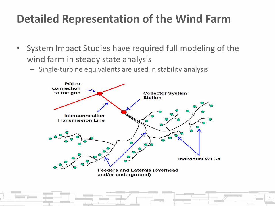
Detailed Representation of the Wind Farm
• System Impact Studies have required full modeling of the wind farm in steady state analysis – Single-turbine equivalents are used in stability analysis
73

Purpose of the Detailed Steady State Review
• Identify tap settings for the unit step-up transformers and the station step-up transformers – Tap settings correspond to the most reasonable voltage conditions on
the collector system and the turbine terminals for a range of different voltage conditions at the POI
• The detailed representation provides direction to the tap settings to be used in the equivalent models used in stability analysis
74

Could Developers Perform the In-Farm Review?
• YES! And they should!
• ISO can provide the standard methodology used in the detailed review for determining initial tap settings
• There may be some remaining concern whether or not the review has to be revisited as a result of later study findings; however, efforts will be made to minimize this likelihood
75

Examples of Reactive Upgrades
• Wind Turbine Generators (Type III and Type IV) – Very limited transient reactive support to the system
• Shunt Compensation
• Static VAR Compensator (SVC)
• STATCOM (DVAR)
• Synchronous Condenser
• Series Capacitors
76
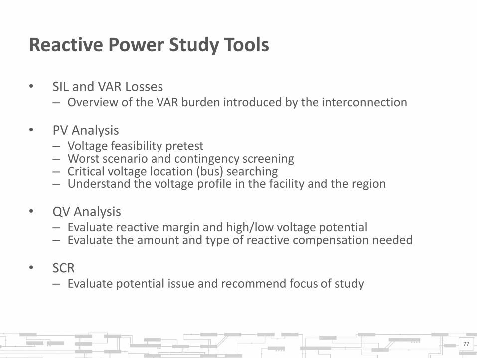
Reactive Power Study Tools
• SIL and VAR Losses – Overview of the VAR burden introduced by the interconnection
• PV Analysis – Voltage feasibility pretest – Worst scenario and contingency screening – Critical voltage location (bus) searching – Understand the voltage profile in the facility and the region
• QV Analysis – Evaluate reactive margin and high/low voltage potential – Evaluate the amount and type of reactive compensation needed
• SCR – Evaluate potential issue and recommend focus of study
77

Wind Farm Reactive Power Control
• Reactive Power Priority – Firstly, ensure the WTGs’ continuous operation, proper terminal
voltages – Then, make the most of the reactive resource for system operation
• Reactive Power Control – Employ voltage control at the POI if, while doing so, the WTGs can
ensure their terminal voltages – If WTGs couldn’t ensure their terminal voltages, terminal voltage study
should be carefully conducted to achieve voltage control at POI, especially for the following conditions: • Weak system (low SCR), pre-existing system voltage issues, significant VAR
burden introduced by the interconnection, long impedance collector system
78

Wind Farm Reactive Power Control, cont.
• Possible Solution for Unacceptable Terminal Voltages – Steady State WTG Terminal Voltages
• Power factor control at POI or voltage control at low voltage side of POI • Shunts and dynamic devices for POI voltage regulation • Apply Load Tap Changing (LTC) at the main transformer to accommodate
high side voltage change
• Dynamic Oscillation Mitigation – Adjust to lower LVRT activation and higher LVRT release voltage
settings – Tune post fault Q and P recovery control to stabilize terminal voltage – Apply SVC/STATCOM/Synchronous Condenser/Series Capacitor – For steady-state voltage solution manipulating shunts and LTC listed
above, detailed model may be needed in dynamic study
79

Wind Farm Reactive Power Control, cont.
• Reactive Power Coordination – A master controller, communication of all reactive resources – WTGs control terminal voltage and compensate internal VAR losses
first – Shunts regulate the POI voltage, compensate external VAR losses, free
up dynamic reactive power from SVC/STATCOM/SC, etc. – Avoid VAR circulation among resources
• Desired future coordination functions – Terminal voltage monitoring and voltage violation controlling – Optimization of individual WTG VAR dispatch – More accurate internal and external network model at the master
controller – Coordination among different wind farm and other facilities
80

AGENDA ITEM 8: SHOULD ISO OPERATING CRITERIA OF ZERO TURBINE TRIPS AFTER NORMAL CONTINGENCIES BE RELAXED? Discussion

AGENDA ITEM 9: ELECTRONIC DATA SUBMITTAL SYSTEM Discussion

AGENDA ITEM 10: COMMUNICATIONS Discussion

AGENDA ITEM 11: NEW NERC REPORTING REQUIREMENTS Discussion

85

APPENDIX I: CONSTRAINTS THAT HAVE BEEN RELEVANT TO WIND INTERCONNECTION

Potential Regional Transmission Constraints
Constraints with all facilities in service
• New Brunswick-New England
• Orrington-South
• Surowiec-South
• Maine-New Hampshire
• NNE-Scobie/394
• North-South
• Orrington-North
• New England-New Brunswick
• New England-New Brunswick + Keene Road Export
Constraints with a facility out of service (OOS)
• Orrington Import
• Maine Yankee South
• New Hampshire-Maine
87

Geographical Map – Regional and Local Constraints in ME
88

Geographical Map – Local Constraints in VT and NH
89

Regional Constraints: Orrington South Interface
• Orrington South – All lines in-service limit is
1,050 MW – 1,200 MW – Single facility out limits
exist – Limits due to thermal,
voltage and stability performance • 200 MW – 1,200 MW
– Resources behind constraint • Existing: ~ 2,120 MW • Proposed: ~ 510 MW
90

Regional Constraints: Surowiec South Interface
• Surowiec South – All lines in-service limit is
1,150 MW – Single facility out limits exist – Limits due to stability
performance (damping, unit stability and post-fault voltage recovery) • 300 MW – 1,150 MW
– Resources behind constraint • Existing: ~ 3,480 MW • Proposed: ~ 1,160 MW
91

Regional Constraints: Orrington Import Interface
• Orrington Import – All lines in-service limits do
not exist – Single facility out limits exist – Limits due to stability
performance (post fault voltage recovery, inter-area instability) • 250 MW – 1,250 MW
– Resources behind constraint • Existing: ~ 1,320 MW • Proposed: ~ 240 MW
92

Local Transmission Constraints
Constraints with all facilities in service
• Maine – Keene Road Export
• New Hampshire – Whitefield South
• Vermont – Sheffield/Highgate Export
Constraints with a facility out of service (OOS)
• Maine – Wyman Hydro Export – Inner Rumford – Outer Rumford – Keene Road + BHE Export – Western ME Export – BHE Export
93

Local Constraints: Maine, Wyman Hydro Export Interface
• Wyman Hydro Export – All lines in-service limits do not
currently exist – Single facility out limits exist
• Based upon two 115 kV lines remaining after limiting contingency
– Limits due to stability performance (damping) • 200 MW – 290 MW
– Resources behind constraint • Existing: ~ 360 MW • Proposed : ~ 215 MW
– Area peak load approx. 15 MW
94

Local Constraints: Maine, Inner Rumford Export Interface
• Inner Rumford Export – All lines in-service limits do
not currently exist – Single facility out limits
exist – Limits due to stability
performance (damping, unit stability and post-fault voltage recovery) • 75 MW – 215 MW
– Resources behind constraint • Existing: ~460 MW • Proposed: ~ 255 MW
– 160 MW (incl. gross mill loads)
95

Local Constraints: Maine, Outer Rumford Export Interface
• Outer Rumford Export – All lines in-service limits do
not exist – Single facility out limits exist – Limits due to stability
performance (damping, unit stability and post-fault voltage recovery) • 75 MW – 215 MW
– Resources behind constraint • Existing: ~645 MW • Proposed: ~ 255 MW
– 290 MW (incl. gross mill loads)
96

Local Constraints: Maine, Western Maine Export Interface
• Western Maine Export – All lines in-service limits do
not exist – Single facility out limits exist – Limits due to stability
performance (damping) • 300 MW – 500 MW
– Resources behind constraint • Existing: ~1050 MW • Proposed: ~ 470 MW
– 420 MW (incl. gross mill loads)
97
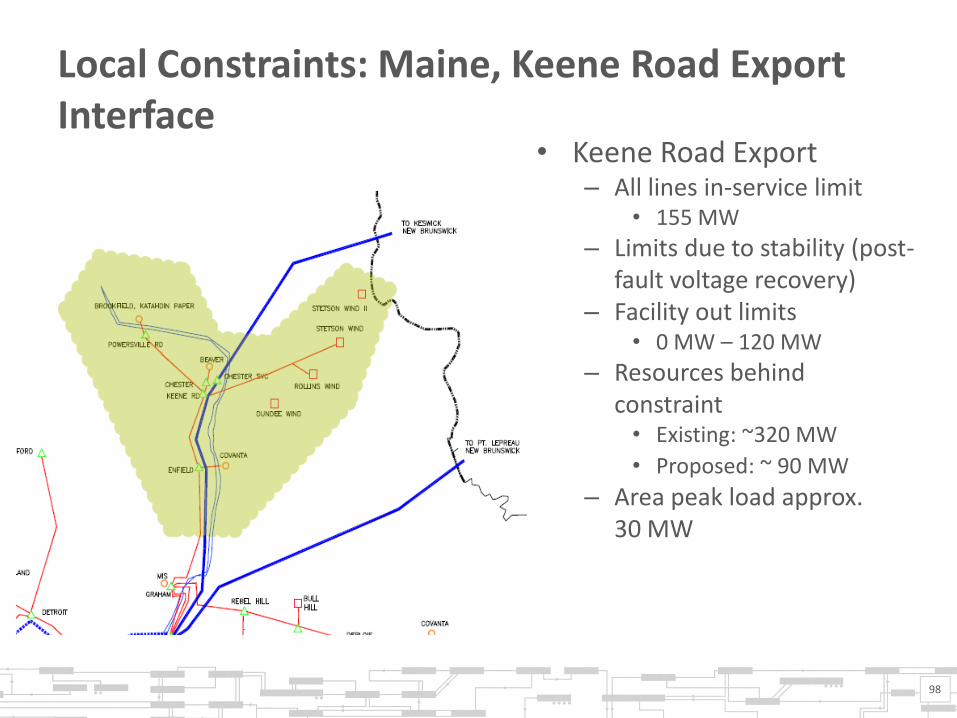
Local Constraints: Maine, Keene Road Export Interface
• Keene Road Export – All lines in-service limit
• 155 MW
– Limits due to stability (post-fault voltage recovery)
– Facility out limits • 0 MW – 120 MW
– Resources behind constraint • Existing: ~320 MW
• Proposed: ~ 90 MW – Area peak load approx.
30 MW
98

Local Constraints: Maine, Bangor Hydro Export Interface
• Bangor Hydro Export – All lines in-service limits do
not exist – Single facility out limits exist – Limits due to stability
performance (damping, instability) • 200 MW – 440 MW
– Resources behind constraint • Existing: ~940 MW • Proposed: ~270 MW
– Area peak load approx. 270 MW
99

Local Constraints: Maine, Bangor Hydro + Keene Road Export Interface
• Bangor Hydro + Keene Road Export – All lines in-service limits do
not exist – Single facility out limits exist – Limits due to stability
performance (damping, instability) • 200 MW – 580 MW
– Resources behind constraint • Existing: ~1,250 MW • Proposed: ~ 360 MW
– Area peak load approx. 300 MW
100

Local Constraints: New Hampshire, Whitefield South
• Whitefield South – All lines in-service limits do exist
• Approximately 150 MW
– Single facility out limits exist and are lower
– Limits are based upon steady state voltage and stability performance
(damping and angular stability) – Resources behind constraint
• Existing: 160 MW • Proposed: ~70 MW
– Area peak load approx. 60 MW
101

Local Constraints: Vermont, Sheffield/Highgate Export
• Sheffield/Highgate Export – All lines in-service limits do exist
• Approximately 250 MW
– Single facility out limits exist and are lower
– Limits are based upon post-contingent, steady state voltage performance
– Resources behind constraint • Existing: 420 MW (including
Highgate) • Proposed: ~60 MW
– Area peak load approx. 120 MW
102

APPENDIX II: TYPES OF REACTIVE RESOURCES

Types of Reactive Resources
• Wind Turbine Generators (Type III and Type IV) – Efficient for terminal voltage control – Good for voltage regulation(need to ensure terminal voltage) – Very limited transient reactive support to the system
• Shunt Compensation – Inexpensive, frees up spinning reactive reserve – However, if system is heavily shunt capacitor compensated, voltage
regulation tends to be poor – Beyond a certain level, stable operation is unattainable when shunts
are used – Can be inoperable for intermittent resources due to quickly changing
output conditions and infeasible from a equipment standpoint due to frequent switching operations
104

Types of Reactive Resources, cont.
• Static VAR Compensator
– Thyristor Controlled Reactor(s) (TCR), filters and Thyristor Switched Capacitors (TSC) or Breaker Switched Capacitors (BSC)
– Reduce voltage fluctuation and Shunt Switching – Support transient voltage and damp system swings – When voltage is low, reactive compensation reduces
• STATCOM(DVAR)
– Voltage Sourced Converters (VSC) used solely for reactive power – Similar performance to SVC but faster, better transient support – Provide full compensation at low voltage
105

Types of Reactive Resources, cont.
• Synchronous Condenser – Increase short circuit ratio – Good for voltage regulation and transient voltage support
• Series Capacitor – Increase the stability limits by reducing effective impedance – Produce more compensation in low-voltage condition and less VAR in
high-voltage condition – Reduce voltage fluctuation and increase effective short circuit capacity – Significant study effort required to ensure no adverse impact due to
Sub-Synchronous Resonance or other interactions
106