wireless access control system - gate openers | gate operators
TRANSCRIPT

Wireless Access Control System
Installation & Programming Instructions
(760) 438-7000 • FAX (760) 438-7043USA & Canada (800) 421-1587 & (800) 392-0123
Toll Free FAX (800) 468-1340www.linearcorp.com
RADIO
RADIO
DECODE
ACCESS GRANTED
PERIPHERALS
READER KEYPAD
ACCESS OUT DATA
NETWORK DATA
ACCESS A
ACCESS B
ACCESS C
OBSTACLE
MAGIC WAND
ACCESS D
SYSTEM
POWER
RESET
DISPLAYCONTRAST
BO 1 O 1 O 1 BO 1 N.O. COM. N.C. N.O. COM. N.C. N.O. COM. N.C. N.O. COM. N.C.
EARTHGROUND
ACCESS OUT KEYPAD IN CHANNEL A CHANNEL B CHANNEL C CHANNEL DREADER IN14 - 24 VAC12 - 35 VDC
AC POWERINPUT
DC POWERINPUTNETWORK
OFF
ON
POWER
RS-232
MEMORY EXPANSION CARD
MEDIUM (64 K)
SMALL (16 K) LARGE (128 K)
X-LARGE (256 K)
WARNING
TURN THE POWER SWITCH OFF BEFORE INSTALLING ORREMOVING THIS MEMORY EXPANSION CARD
SEVEREELECTRICAL
DAMAGE
RELAYS
EXTERNAL CONTROL
For AM/IIVersion 5.0
*
5 6
7 8 9
0 #
1 2 3
4
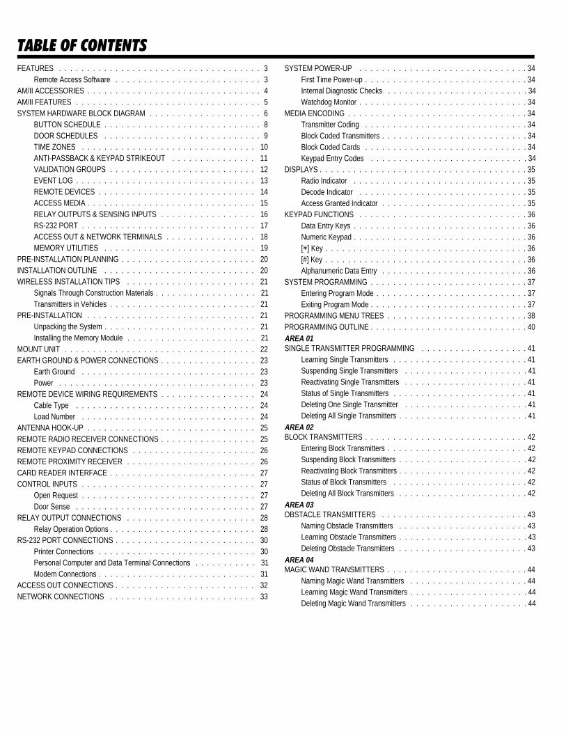
TABLE OF CONTENTSFEATURES . . . . . . . . . . . . . . . . . . . . . . . . . . . . . . . . . . . . 3
Remote Access Software . . . . . . . . . . . . . . . . . . . . . . . . . . 3AM/II ACCESSORIES . . . . . . . . . . . . . . . . . . . . . . . . . . . . . . . 4AM/II FEATURES . . . . . . . . . . . . . . . . . . . . . . . . . . . . . . . . . 5SYSTEM HARDWARE BLOCK DIAGRAM . . . . . . . . . . . . . . . . . . . . 6
BUTTON SCHEDULE . . . . . . . . . . . . . . . . . . . . . . . . . . . . 8DOOR SCHEDULES . . . . . . . . . . . . . . . . . . . . . . . . . . . . 9TIME ZONES . . . . . . . . . . . . . . . . . . . . . . . . . . . . . . . 10ANTI-PASSBACK & KEYPAD STRIKEOUT . . . . . . . . . . . . . . . 11VALIDATION GROUPS . . . . . . . . . . . . . . . . . . . . . . . . . . 12EVENT LOG . . . . . . . . . . . . . . . . . . . . . . . . . . . . . . . . 13REMOTE DEVICES . . . . . . . . . . . . . . . . . . . . . . . . . . . . 14ACCESS MEDIA . . . . . . . . . . . . . . . . . . . . . . . . . . . . . . 15RELAY OUTPUTS & SENSING INPUTS . . . . . . . . . . . . . . . . . 16RS-232 PORT . . . . . . . . . . . . . . . . . . . . . . . . . . . . . . . 17ACCESS OUT & NETWORK TERMINALS . . . . . . . . . . . . . . . . 18MEMORY UTILITIES . . . . . . . . . . . . . . . . . . . . . . . . . . . 19
PRE-INSTALLATION PLANNING . . . . . . . . . . . . . . . . . . . . . . . . 20INSTALLATION OUTLINE . . . . . . . . . . . . . . . . . . . . . . . . . . . 20WIRELESS INSTALLATION TIPS . . . . . . . . . . . . . . . . . . . . . . . 21
Signals Through Construction Materials . . . . . . . . . . . . . . . . . . 21Transmitters in Vehicles . . . . . . . . . . . . . . . . . . . . . . . . . . 21
PRE-INSTALLATION . . . . . . . . . . . . . . . . . . . . . . . . . . . . . . 21Unpacking the System . . . . . . . . . . . . . . . . . . . . . . . . . . . 21Installing the Memory Module . . . . . . . . . . . . . . . . . . . . . . . 21
MOUNT UNIT . . . . . . . . . . . . . . . . . . . . . . . . . . . . . . . . . . 22EARTH GROUND & POWER CONNECTIONS . . . . . . . . . . . . . . . . . 23
Earth Ground . . . . . . . . . . . . . . . . . . . . . . . . . . . . . . . 23Power . . . . . . . . . . . . . . . . . . . . . . . . . . . . . . . . . . . 23
REMOTE DEVICE WIRING REQUIREMENTS . . . . . . . . . . . . . . . . . 24Cable Type . . . . . . . . . . . . . . . . . . . . . . . . . . . . . . . . 24Load Number . . . . . . . . . . . . . . . . . . . . . . . . . . . . . . . 24
ANTENNA HOOK-UP . . . . . . . . . . . . . . . . . . . . . . . . . . . . . . 25REMOTE RADIO RECEIVER CONNECTIONS . . . . . . . . . . . . . . . . . 25REMOTE KEYPAD CONNECTIONS . . . . . . . . . . . . . . . . . . . . . . 26REMOTE PROXIMITY RECEIVER . . . . . . . . . . . . . . . . . . . . . . . 26CARD READER INTERFACE . . . . . . . . . . . . . . . . . . . . . . . . . . 27CONTROL INPUTS . . . . . . . . . . . . . . . . . . . . . . . . . . . . . . . 27
Open Request . . . . . . . . . . . . . . . . . . . . . . . . . . . . . . . 27Door Sense . . . . . . . . . . . . . . . . . . . . . . . . . . . . . . . . 27
RELAY OUTPUT CONNECTIONS . . . . . . . . . . . . . . . . . . . . . . . 28Relay Operation Options . . . . . . . . . . . . . . . . . . . . . . . . . . 28
RS-232 PORT CONNECTIONS . . . . . . . . . . . . . . . . . . . . . . . . . 30Printer Connections . . . . . . . . . . . . . . . . . . . . . . . . . . . . 30Personal Computer and Data Terminal Connections . . . . . . . . . . . 31Modem Connections . . . . . . . . . . . . . . . . . . . . . . . . . . . . 31
ACCESS OUT CONNECTIONS . . . . . . . . . . . . . . . . . . . . . . . . . 32NETWORK CONNECTIONS . . . . . . . . . . . . . . . . . . . . . . . . . . 33
SYSTEM POWER-UP . . . . . . . . . . . . . . . . . . . . . . . . . . . . . . 34First Time Power-up . . . . . . . . . . . . . . . . . . . . . . . . . . . . . 34Internal Diagnostic Checks . . . . . . . . . . . . . . . . . . . . . . . . . 34Watchdog Monitor . . . . . . . . . . . . . . . . . . . . . . . . . . . . . . 34
MEDIA ENCODING . . . . . . . . . . . . . . . . . . . . . . . . . . . . . . . . 34Transmitter Coding . . . . . . . . . . . . . . . . . . . . . . . . . . . . . 34Block Coded Transmitters . . . . . . . . . . . . . . . . . . . . . . . . . . 34Block Coded Cards . . . . . . . . . . . . . . . . . . . . . . . . . . . . . 34Keypad Entry Codes . . . . . . . . . . . . . . . . . . . . . . . . . . . . 34
DISPLAYS . . . . . . . . . . . . . . . . . . . . . . . . . . . . . . . . . . . . . 35Radio Indicator . . . . . . . . . . . . . . . . . . . . . . . . . . . . . . . 35Decode Indicator . . . . . . . . . . . . . . . . . . . . . . . . . . . . . . 35Access Granted Indicator . . . . . . . . . . . . . . . . . . . . . . . . . . 35
KEYPAD FUNCTIONS . . . . . . . . . . . . . . . . . . . . . . . . . . . . . . 36Data Entry Keys . . . . . . . . . . . . . . . . . . . . . . . . . . . . . . . 36Numeric Keypad . . . . . . . . . . . . . . . . . . . . . . . . . . . . . . . 36[*] Key . . . . . . . . . . . . . . . . . . . . . . . . . . . . . . . . . . . . 36[#] Key . . . . . . . . . . . . . . . . . . . . . . . . . . . . . . . . . . . . 36Alphanumeric Data Entry . . . . . . . . . . . . . . . . . . . . . . . . . . 36
SYSTEM PROGRAMMING . . . . . . . . . . . . . . . . . . . . . . . . . . . . 37Entering Program Mode . . . . . . . . . . . . . . . . . . . . . . . . . . . 37Exiting Program Mode . . . . . . . . . . . . . . . . . . . . . . . . . . . . 37
PROGRAMMING MENU TREES . . . . . . . . . . . . . . . . . . . . . . . . . 38PROGRAMMING OUTLINE . . . . . . . . . . . . . . . . . . . . . . . . . . . . 40AREA 01SINGLE TRANSMITTER PROGRAMMING . . . . . . . . . . . . . . . . . . . 41
Learning Single Transmitters . . . . . . . . . . . . . . . . . . . . . . . . 41Suspending Single Transmitters . . . . . . . . . . . . . . . . . . . . . . 41Reactivating Single Transmitters . . . . . . . . . . . . . . . . . . . . . . 41Status of Single Transmitters . . . . . . . . . . . . . . . . . . . . . . . . 41Deleting One Single Transmitter . . . . . . . . . . . . . . . . . . . . . . 41Deleting All Single Transmitters . . . . . . . . . . . . . . . . . . . . . . . 41
AREA 02BLOCK TRANSMITTERS . . . . . . . . . . . . . . . . . . . . . . . . . . . . . 42
Entering Block Transmitters . . . . . . . . . . . . . . . . . . . . . . . . . 42Suspending Block Transmitters . . . . . . . . . . . . . . . . . . . . . . . 42Reactivating Block Transmitters . . . . . . . . . . . . . . . . . . . . . . . 42Status of Block Transmitters . . . . . . . . . . . . . . . . . . . . . . . . 42Deleting All Block Transmitters . . . . . . . . . . . . . . . . . . . . . . . 42
AREA 03OBSTACLE TRANSMITTERS . . . . . . . . . . . . . . . . . . . . . . . . . . 43
Naming Obstacle Transmitters . . . . . . . . . . . . . . . . . . . . . . . 43Learning Obstacle Transmitters . . . . . . . . . . . . . . . . . . . . . . . 43Deleting Obstacle Transmitters . . . . . . . . . . . . . . . . . . . . . . . 43
AREA 04MAGIC WAND TRANSMITTERS . . . . . . . . . . . . . . . . . . . . . . . . . 44
Naming Magic Wand Transmitters . . . . . . . . . . . . . . . . . . . . . 44Learning Magic Wand Transmitters . . . . . . . . . . . . . . . . . . . . . 44Deleting Magic Wand Transmitters . . . . . . . . . . . . . . . . . . . . . 44

AREA 05ENTRY CODES . . . . . . . . . . . . . . . . . . . . . . . . . . . . . . . . . 45
Entering Entry Codes . . . . . . . . . . . . . . . . . . . . . . . . . . . 45Suspending Entry Codes . . . . . . . . . . . . . . . . . . . . . . . . . 45Reactivating Entry Codes . . . . . . . . . . . . . . . . . . . . . . . . . 45Status of Entry Codes . . . . . . . . . . . . . . . . . . . . . . . . . . . 45Deleting One Single Entry Code . . . . . . . . . . . . . . . . . . . . . . 45Deleting All Entry Codes . . . . . . . . . . . . . . . . . . . . . . . . . . 45
AREA 06BLOCK CARD CODES . . . . . . . . . . . . . . . . . . . . . . . . . . . . . 46
Entering Block Card Codes . . . . . . . . . . . . . . . . . . . . . . . . 46Suspending Block Card Codes . . . . . . . . . . . . . . . . . . . . . . 46Reactivating Block Card Codes . . . . . . . . . . . . . . . . . . . . . . 46Status of Block Card Codes . . . . . . . . . . . . . . . . . . . . . . . . 46Deleting All Block Card Codes . . . . . . . . . . . . . . . . . . . . . . . 46
AREA 07TELEPHONE ENTRY NUMBERS . . . . . . . . . . . . . . . . . . . . . . . . 47
Entering Tenant Names & Numbers . . . . . . . . . . . . . . . . . . . . 47Deleting Directory Entries . . . . . . . . . . . . . . . . . . . . . . . . . 47
AREA 10VALIDATION GROUPS . . . . . . . . . . . . . . . . . . . . . . . . . . . . . 48
Configuring Validation Groups . . . . . . . . . . . . . . . . . . . . . . . 48AREA 11BUTTON SCHEDULES . . . . . . . . . . . . . . . . . . . . . . . . . . . . . 49
Setting the Channel “A” Button Schedule . . . . . . . . . . . . . . . . . 49Setting the Channel “B” Button Schedule . . . . . . . . . . . . . . . . . 49Setting the Channel “C” Button Schedule . . . . . . . . . . . . . . . . . 49Setting the Channel “D” Button Schedule . . . . . . . . . . . . . . . . . 49
AREA 12DOOR SCHEDULES . . . . . . . . . . . . . . . . . . . . . . . . . . . . . . 50
Setting the Door Schedules . . . . . . . . . . . . . . . . . . . . . . . . 50AREA 13TIME ZONES . . . . . . . . . . . . . . . . . . . . . . . . . . . . . . . . . . 51
Setting the Time Zones . . . . . . . . . . . . . . . . . . . . . . . . . . 51AREA 20TIME AND CALENDAR . . . . . . . . . . . . . . . . . . . . . . . . . . . . . 52
Setting the Time . . . . . . . . . . . . . . . . . . . . . . . . . . . . . . 52Setting the Date . . . . . . . . . . . . . . . . . . . . . . . . . . . . . . 52Daylight Savings Option . . . . . . . . . . . . . . . . . . . . . . . . . . 52Setting Keypad Downlight Time . . . . . . . . . . . . . . . . . . . . . . 52Setting Holiday Dates . . . . . . . . . . . . . . . . . . . . . . . . . . . 52Setting Expiring Holiday Dates . . . . . . . . . . . . . . . . . . . . . . 52
AREA 21RELAY SETUP . . . . . . . . . . . . . . . . . . . . . . . . . . . . . . . . . 53
Relay Timing Options . . . . . . . . . . . . . . . . . . . . . . . . . . . 53Relay Programming . . . . . . . . . . . . . . . . . . . . . . . . . . . . 53
AREA 22SYSTEM SETUP . . . . . . . . . . . . . . . . . . . . . . . . . . . . . . . . 54
Setting Installation and Unit Names . . . . . . . . . . . . . . . . . . . . 54Setting Event Log Limits . . . . . . . . . . . . . . . . . . . . . . . . . . 54Setting Anti-Passback Time . . . . . . . . . . . . . . . . . . . . . . . . 54Setting Intregral Radio Direction . . . . . . . . . . . . . . . . . . . . . . 54Setting Network Address . . . . . . . . . . . . . . . . . . . . . . . . . 54Setting Keypad Strike Outs . . . . . . . . . . . . . . . . . . . . . . . . 54Setting Door Ajar Time . . . . . . . . . . . . . . . . . . . . . . . . . . . 54Setting Local Password . . . . . . . . . . . . . . . . . . . . . . . . . . 54Setting Remote Password . . . . . . . . . . . . . . . . . . . . . . . . . 54Setting Priority Access Password . . . . . . . . . . . . . . . . . . . . . 54
AREA 23Facility/Site Codes . . . . . . . . . . . . . . . . . . . . . . . . . . . . . . . . 55
System Site Code . . . . . . . . . . . . . . . . . . . . . . . . . . . . . 55Transmitter Facility Code . . . . . . . . . . . . . . . . . . . . . . . . . 55Card Facility Codes . . . . . . . . . . . . . . . . . . . . . . . . . . . . 55
AREA 24RS-232 PORT SETUP . . . . . . . . . . . . . . . . . . . . . . . . . . . . . 56
Setting RS-232 Device . . . . . . . . . . . . . . . . . . . . . . . . . . 56Changing Modem Initialization Strings . . . . . . . . . . . . . . . . . . . 56Setting Modem Termination String . . . . . . . . . . . . . . . . . . . . 56
AREA 25CONFIGURE REMOTE DEVICES . . . . . . . . . . . . . . . . . . . . . . . 57
Remote Device Programming . . . . . . . . . . . . . . . . . . . . . . . 57AREA 26CONFIGURE ACCESS OUT . . . . . . . . . . . . . . . . . . . . . . . . . . 58
Access Out Application Note . . . . . . . . . . . . . . . . . . . . . . . 58Access Out Setup . . . . . . . . . . . . . . . . . . . . . . . . . . . . . 58
AREA 27TELEPHONE ENTRY SETUP . . . . . . . . . . . . . . . . . . . . . . . . . . 59
Configuring Directory . . . . . . . . . . . . . . . . . . . . . . . . . . . 59Setting PBX Dialing Digit . . . . . . . . . . . . . . . . . . . . . . . . . 59Setting Talk Time . . . . . . . . . . . . . . . . . . . . . . . . . . . . . 59Editing Display Messages . . . . . . . . . . . . . . . . . . . . . . . . . 59Deleting All Telephone Entries . . . . . . . . . . . . . . . . . . . . . . 59Adjusting the Speaker/Microphone Balance . . . . . . . . . . . . . . . . 59Set Priority Access Function . . . . . . . . . . . . . . . . . . . . . . . . 59
AREA 29MEMORY MODULE UTILITIES . . . . . . . . . . . . . . . . . . . . . . . . . 60
Sending Memory Module . . . . . . . . . . . . . . . . . . . . . . . . . 60Receiving Memory Module . . . . . . . . . . . . . . . . . . . . . . . . 60Copying Memory Module . . . . . . . . . . . . . . . . . . . . . . . . . 60Printing Memory Module . . . . . . . . . . . . . . . . . . . . . . . . . . 60Initializing Memory Module . . . . . . . . . . . . . . . . . . . . . . . . 60
AREA 30SYSTEM REPORTS/UTILITIES . . . . . . . . . . . . . . . . . . . . . . . . . 61
Printing System Report . . . . . . . . . . . . . . . . . . . . . . . . . . 61Printing Single Transmitter Report . . . . . . . . . . . . . . . . . . . . . 61Printing Block Transmitter Report . . . . . . . . . . . . . . . . . . . . . 61Printing Entry Code Report . . . . . . . . . . . . . . . . . . . . . . . . 61Printing Block Card Report . . . . . . . . . . . . . . . . . . . . . . . . 61Printing Telephone Entry Report . . . . . . . . . . . . . . . . . . . . . 61Printing Event Log . . . . . . . . . . . . . . . . . . . . . . . . . . . . . 61
OPERATION OVERVIEW . . . . . . . . . . . . . . . . . . . . . . . . . . . . 62Standard Operation . . . . . . . . . . . . . . . . . . . . . . . . . . . . 62Manual Operation . . . . . . . . . . . . . . . . . . . . . . . . . . . . . 62Magic Wand Transmitters . . . . . . . . . . . . . . . . . . . . . . . . . 62Obstacle Transmitters . . . . . . . . . . . . . . . . . . . . . . . . . . . 62
SPECIFICATIONS . . . . . . . . . . . . . . . . . . . . . . . . . . . . . . . . 63Outputs . . . . . . . . . . . . . . . . . . . . . . . . . . . . . . . . . . 63Inputs . . . . . . . . . . . . . . . . . . . . . . . . . . . . . . . . . . . 63Hardware . . . . . . . . . . . . . . . . . . . . . . . . . . . . . . . . . 63Construction . . . . . . . . . . . . . . . . . . . . . . . . . . . . . . . . 63
INDEX . . . . . . . . . . . . . . . . . . . . . . . . . . . . . . . . . . . . . . 64LINEAR LIMITED WARRANTY . . . . . . . . . . . . . . . . . . . . . . . . . 66
1

INTRODUCTIONThe AM/II is designed for a broad range of access controlapplications. Its wireless design with the proven MegaCoderadio format, the Wiegand and RS-232 interfaces, make iteasily adaptable for virtually any access control requirement.The AM/II contains a high-gain superheterodyne UHF receiver.When used with an external antenna, signals can be receivedfrom up to 200 feet away. Two lockable metal enclosures areavailable to house the AM/II.Four dry contact relay outputs are provided to activate fouraccess devices, such as door strikes, barrier gates, automaticsliding gates and automatic doors. The relay outputs can alsobe used for alarm contact shunting, operator obstacletriggering, and alarm activation. Two open request pushbuttoninputs are supplied for hardwire activation of the accessdevices. Two door sense inputs allow detection of proppedopen doors.The AM/II has an RS-232 interface (bi-directional). The systemcan be linked to a printer or personal computer. The event logfeature, for example, makes it possible to keep track of howmany employees are on premises, which employees arepresent, and when they clock in and out. With connection to apersonal computer, the AM/II can be programmed locally orremotely through the telephone system with standard Hayescompatible modems. System reports can be printed orcaptured from the RS-232 port.
The Wiegand interface is for connect ion to othermanufacturer’s access control systems. The AM/II can act asa wireless receiver for an existing access control system. Wheninterconnected to a Sentex Infinity system, the AM/II cansimulate two Sentex card readers, receiving signals fromthousands of transmitters. The AM/II also supports the industrystandard Wiegand26 and Securakey31 data formats forconnecting to other access control panels.Up to eight AM/II’s can be networked together allowinginformation sharing between the units. A common event log isretained for all of the networked units.Four different size memory modules are available. The small,medium, large and x-large modules allow tailoring the systemto meet the requirements of the installation. The larger thememory module, the more transmitter ID codes and loggedevents can be stored.Additional remote accessory devices can be connected to theAM/II. A rugged, die cast, weatherproof keypad (AM-KP) formanual input of entry codes. A card reader interface (AM-CRI)can connect to one or two card readers. A proximity receiver(AM-RPR) provides ultra-short range radio reception fortransmitters. A remote radio receiver (AM-RRR) can be usedto extend the reception capabilities of the AM/II. Up to sixremote accessory devices can be used with each AM/II unit.
OKBACK NEXT
AM/II
Barrier Gate with ControlledDoor, Remote Receivers andRemote Keypads.Access is Controled with Time Zones.
Safety EdgeTransmitter
Modem for RemoteAccess & Programming
Barrier Gate
Controlled Door
Keypad &RemoteReceiver
User Tx
User Tx
ProximityReceiver
STANDARD 2-WIRE DOORSTRIKECONNECTION
6-WIRELOCAL BUS
Keypad
DoorStrike
6-WIRELOCAL BUS
STANDARD 2-WIRE SIGNALCONNECTION
2

FEATURES✶ Ideally suited for gated communities, condos, airports,
parking garages, municipal gated parking, office buildings,government buildings, hospitals, factories, utilitycompanies, computer facilities, museums, warehouses,dormitories, banks, libraries, retail stores, hotels/motels,educational facilities, small commercial buildings andrecreational facilities.
✶ Controls up to four access devices.✶ Supports thousands of transmitters, entry codes and card
codes (depends on memory module size).✶ MegaCode radio format features over one million possible
transmitter identification codes.✶ Remote activation from up to 200 feet away.✶ Integral 2 line by 24 character backlit LCD display.✶ Real-time print log (RS-232 output to a line printer).✶ Remote and local programming with a personal computer.✶ Sentex30, Securakey31, and Wiegand26 compatible output
to connect to other access control panels.✶ Block coding for transmitters and cards (just the first and last
number in a “block” needs to be programmed).✶ Magic wand support (special transmitter for maintenance
personnel).✶ Obstacle-sensing support with Linear’s MGT Safety Edge
transmitter.✶ Two door sensing inputs for propped open doors.
✶ Automatic door relock when door sense input is used.✶ Two request to exit inputs for pushbutton or knox box
activation.✶ Time scheduled relay activation, 15 time zones with 4
periods each.✶ Time zone access validation, 15 time zones with 4 periods
each.✶ Day of week and holiday access validation, up to 24 expiring
holidays and 24 non-expiring holidays.✶ Door access restriction for each validation group.✶ Timed anti-passback modes.
Remote Access SoftwareEither of the following two Windows based softwareprograms can be downloaded f rom our website(www.linearcorp.com)✶ Access Base - used in networks or single AM/II installations.✶ Account Manager - used in non-networked, single AM/II
installations.
0 7 : 0 0 A C C E S S U S E R 20 7 : 1 0 A C C E S S U S E R 1 70 7 : 1 4 A C C E S S U S E R 3 40 7 : 1 5 A C C E S S U S E R 4 50 7 : 1 9 A C C E S S U S E R 2 70 7 : 2 3 A C C E S S U S E R 5 60 7 : 2 4 A C C E S S U S E R 1 20 7 : 2 6 A C C E S S U S E R 1 30 7 : 2 6 A C C E S S U S E R 2 30 7 : 2 7 A C C E S S U S E R 8 70 7 : 2 8 A C C E S S U S E R 6 70 7 : 2 9 A C C E S S U S E R 9 8
L O B B Y
ACCOUNTING
S E R V I C E
S A L E S
P R E S I D E N T
V . P .V . P .
S A L E S P U R C H .
E N G I N E E R I N G
B A T H B A T H
COMPUTER
ROOM
S T O R .
C O P I E RA R E A
C H I E FE N G .
L A B
AM/II(Two Networked Units)
Small Commercial Installationwith Two Time Zones. FourDoors: Customer Entrance,Employee Entrance, ComputerRoom & President's Back Door
Printer forEvent Logging
Keypad
CardReader
EMPLOYEEENTRANCE
CUSTOMERENTRANCE
CRTEventLogging
RECEPTIONIST
DoorRelease
CardReader
COMPUTER ROOMSPECIAL ACCESS
Modem forRemoteProgramming
OKBACK NEXT
CardReader
PRESIDENT'S OFFICESPECIAL ACCESS
3

AM/II ACCESSORIES
*
5 6
7 8 9
0 #
1 2 3
4
M D T K
2 - B u t t o n M e g a C o d e T r a n s m i t t e r
T o p a n d f r o n t b u t t o n sf u n c t i o n t h e s a m e t oc o n t r o l a s i n g l er e l a y c h a n n e l .
3 - B u t t o n M e g a C o d e T r a n s m i t t e r
T w o f r o n t b u t t o n s a n d at o p b u t t o n c a n b e u s e dw i t h a n y r e l a y c h a n n e l .
2 - B u t t o n M e g a C o d eM i n i T r a n s m i t t e r
D e s i g n e d t o b e u s e d w i t ht h e k e y c h a i n p r o v i d e d . A c t i v a t e s t w o r e l a y c h a n n e l s .
1 - B u t t o n M e g a C o d eM i n i T r a n s m i t t e r
D e s i g n e d t o b e u s e d w i t ht h e k e y c h a i n p r o v i d e d . A c t i v a t e s o n e r e l a y c h a n n e l .
M e g a C o d e W i r e l e s s K e y p a d
U s e r c o d e i s e n t e r e d o n k e y p a d .K e y p a d h a s w e a t h e r - p r o o fc o n s t r u c t i o n , e a s y t o r e a d n u m b e r s a n d i s b a c k l i t f o ru s e a t n i g h t . C a n b e u s e d f o r u pt o 1 5 2 4 s i n g l e t r a n s m i t t t e r c o d e s .
M D T - 2
SINGLE & BLOCK CODEDTRANSMITTERS
REMOTE ACCESSORY DEVICES
5 - B u t t o n M e g a C o d e T r a n s m i t t e r
C a n c o n t r o l a l l r e l a yc h a n n e l s o r b e u s e d a sa m a g i c w a n d t r a n s m i t t e r .
M D T - 4M D T - 1
A C T - 2 2A C T - 2 1
M G TA M - K P
A M - R R R
A M - C R I A M - R P R
S u p e r v i s e d G a t e S a f e t yE d g e T r a n s m i t t e r
C o n n e c t s t o s a f e t y e d g es e n s o r . A c t i v a t e s o b s t a c l er e l a y c h a n n e l .
E n t r y K e y p a d
O u t d o o r h o u s i n g w i t hl i g h t e d k e y p a d a n d t w oi n d i c a t o r s . A c t i v a t e s o n er e l a y c h a n n e l .
E X A - 1 0 0 0
E X A - 2 0 0 0
R e m o t e A n t e n n a s
D i r e c t i o n a l a n d o m n i -d i r e c t i o n a l a n t e n n a s f o rr e m o t e p l a c e m e n t i n b e s tr e c e p t i o n a r e a s .
R e m o t e R a d i o R e c e i v e r
H i g h - g a i n r e m o t e r a d i or e c e i v e r w i t h o u t d o o rh o u s i n g .
C a r d R e a d e rI n t e r f a c e
C o n n e c t s t o o n e o rt w o 2 6 - b i t o r 3 1 - b i t c a r dr e a d e r s . F u n c t i o n s a st w o r e m o t e d e v i c e s .
R e m o t e P r o x i m i t yR e c e i v e r
R e c e i v e s t r a n s m i t t e rs i g n a l s f r o m i n c h e sa w a y . F o r t r a n s m i t t e ra c t i v a t i o n o f s p e c i f i ca c c e s s p o i n t .
4

AM/II FEATURES
1. MEMORY EXPANSION CARDPlug-in memory module. Four sizes available: small, medium, large andjumbo.
2. RESET BUTTONResets and restarts the microprocessor. Runs startup tests.
3. POWER LIGHTIndicates that DC or AC power is being applied to the unit and that thePOWER switch is turned on.
4. DISPLAY CONTRAST CONTROLAdjusts the contrast of the unit’s LCD display. Allows setting the displayfor maximum readability for different viewing angles.
5. LCD DISPLAYBacklit, 24-character-per-line, 2-line LCD display. Displays systemoperation and programming information.
6. RADIO RANGE KNOBControls the gain of the radio receiver. Used to limit the maximumoperating range of transmitters. Turn clockwise for more gain,counterclockwise for less gain.
7. ANTENNA INPUTFor connection to the EXA-1000 omni-directional or EXA-2000 directionalremote antenna.
8. DATA ENTRY KEYSArrow keys are used to scroll through displayed menu trees. OK key isused as an enter key to accept data entered or selected.
9. RADIO INDICATORThe RADIO light indicates the presence of RF signal into the unit’sreceiver.
10. NUMERIC KEYPADUsed for entering data while programming the AM/II.
11. RS-232 PORTConnects to a serial line printer, PC or data terminal for logging accesstransactions. For local programming with a PC or remote programmingwith a PC and a modem. Also used to interconnect two AM/II units to copythe memory between systems.
12. POWER SWITCHControls the DC and AC power inputs. This is the master power switchfor the AM/II.
13. EARTH GROUND TERMINALFor connection to a good earth ground. For electrical safety and optimumlightning protection, this connection is mandatory.
14. POWER TERMINALSDC power input terminals for 12 to 35 VDC. AC power input terminals for14 to 24 VAC. Use either AC or DC power, DO NOT USE BOTH.
15. RELAY INDICATORS AND ACCESS BUTTONSIndicators will light when an output relay is activated. Outputs can beactivated (open) by a transmitter or locked open by pressing an ACCESSbutton.
16. EXTERNAL CONTROL INDICATORSMAGIC WAND indicator lights when the special “MAGIC WAND”transmitter is activated by a system administrator. OBSTACLE indicatorlights when a signal from a Model MGT safety edge transmitter isreceived.
17. RELAY TERMINALSConnects to the access device to be controlled (door strike, gate operator,etc.). Open request switch inputs are provided for relay channels A & B.
18. WIRING STRAIN RELIEF HOOKSStrain relief hooks are provided on the bottom of the AM/II case. Afterwiring is complete, wires can be zip-tied to the strain relief hooks.
19. PERIPHERALS INDICATORSThe DECODE light indicates that the data being received is a valid formatthat the unit recognizes. The ACCESS GRANTED indicator lights whena device that is allowed to have access is triggered. The ACCESS IN andACCESS OUT indicators light when data is being sent or received fromthe remote devices.
20. READER IN TERMINALSConnects to remote accessory devices.
21. KEYPAD IN TERMINALSConnects to remote accessory devices.
22. ACCESS OUT TERMINALSAccessNet Data Bus for connection to other access control units. Sentexaccess out format is programmable for connection to Sentex Infinitysystems. Wiegand26 and SecuraKey31 access out formats areprogrammable for connection to Wiegand inputs on other access controlunits.
23. NETWORK TERMINALSFor connection to other AM/II units. Up to 8 units can be networkedtogether.
EXPANSION MEMORY CARD RADIO
RADIO
DECODE
ACCESS GRANTED
PERIPHERALS
READER KEYPAD
ACCESS OUT DATA
ACCESS IN DATA
RELAYS
ACCESS A
ACCESS B
ACCESS C
EXTERNAL CONTROL
OBSTACLE
MAGIC WAND
ACCESS D
SYSTEM
POWER
RESET
DISPLAYCONTRAST
BO 1 O 1 O 1 BO 1 N.O. COM. N.C. N.O. COM. N.C. N.O. COM. N.C. N.O. COM. N.C.
EARTHGROUND
ACCESS OUT KEYPAD IN CHANNEL A CHANNEL B CHANNEL C CHANNEL DREADER IN14 - 24 VAC12 - 35 VDC
AC POWERINPUT
DC POWERINPUTNETWORK
O K
OFF
ON
POWER
RS-232
MEMORY EXPANSION CARD
MEDIUM (64 K)
SMALL (16 K) LARGE (128 K)
X-LARGE (256 K)
WARNING
TURN THE POWER SWITCH OFF BEFORE INSTALLING ORREMOVING THIS MEMORY EXPANSION CARD
SEVEREELECTRICAL
DAMAGE
1 41 51 61 71 81 92 02 1
1
2
3 45 6 7
8 9
1 01 1
1 2
2 2
1 3
2 3
5

SYSTEM HARDWARE BLOCK DIAGRAM
RADIO
MICROPROCESSOR
INDICATORS DISPLAY KEYBOARD
MEMORYMODULE
RS-232PORT
NETWORKTERMINALS
ACCESS OUTTERMINALS
KEYPADTERMINALS
READERTERMINALS
DOOR SENSE & OPEN REQ.
RELAYTERMINALS
USER'STRANSMITTERS
OBSTACLETRANSMITTERS
ANOTHERAM/II
ANOTHERAM/II
UP TO 8NETWORK
UNITS
EXTERNALACCESS
CONTROLPANEL
AM-KPKEYPAD
[DV4]
AM-KPKEYPAD
[DV5]
AM-KPKEYPAD
[DV6]
AM-RPRRECEIVER
[DV1]
AM-RRRRECEIVER
[DV2]
AM-CRIREADER
[DV3]
MAGNETICSWITCHES
& PUSHBUTTONS
ACCESS DEVICES(DOOR STRIKES,
OPERATORS)7
1
2 3
86
5
4
AM/II CONTROL
6

➀AM/II CONTROL
The AM/II is a microprocessor based, world class accesscontrol system with a built-in superheterodyne radio receiver.The microprocessor runs the entire system, granting access,performing system “housekeeping” functions, displayinginformation, reading inputs and controlling outputs.Programming information and event logs are stored in theremovable memory module. The soft touch silicone keypad andnumeric keys are used for data entry. The plug-in terminalblocks connect to access devices, power, remote devices andsensing inputs. The RS-232 port connects to external computerequipment for event logging and system programming.
➁RADIO TRANSMITTERS
Many models of transmitters can be used with the AM/II. Someare individually coded, others are coded in blocks of numbers.Both code types will appear to function the same to the endusers. The users will activate their transmitter to attempt to gainaccess. When the transmitted signal is detected by an AM/IIreceiver, the control decides if the user is currently allowedaccess. If the programming in the AM/II determines that theuser can have access at that time, the programmed outputrelay will activate. Model MGT gate obstacle transmitters canalso send signals to the AM/II.
➂EXTERNAL ANTENNA
The AM/II control has a type “F” antenna connector. Theexternal antenna is connected with co-ax cable to theconnector. A Model EXA-1000 (omni-directional), or ModelEXA-2000 (directional) antenna is used to receive signals fromthe user’s transmitters. The radio gain control knob can be usedto custom tailor the reception area to the installation.
➃ACCESS DEVICES
The access devices wired to the relay terminals control specificaccess portals. When a user is granted access by the AM/II theaccess device activates (usually for a timed period).
➄OPEN REQUEST AND DOOR SENSE
INPUTSThe open request inputs wire to pushbuttons or knox boxes sothat users can activate access devices without needing theircard code or transmitter. Open request pushbuttons are usuallynext to the controlled portal inside the controlled area. Doorsense inputs are wired to normally closed magnetic ormechanical switches attached to the door.
➅REMOTE DEVICES
The remote devices communicate with the AM/II through acommon electrical buss. Each device is set to a unique deviceaddress so the AM/II can recognize each unit as an individual.Currently available remote devices include entry keypads,remote radio receivers, radio proximity receivers and cardreader interfaces.
➆EXTERNAL ACCESS CONTROL
Access control panels from other manufacturers can beconnected to the AM/II. The AM/II can serve as a remote devicefor the external panel. The external panel can validate the datacoming from the AM/II and perform its own access functions.
➇NETWORKED UNITS
Up to eight AM/II’s can be networked together to function inunison. Each AM/II functions as an independent unit, butprogramming and event logging is shared between all units.Cards, codes and transmitters can be programmed to activatea specific AM/II unit.
7

BUTTON SCHEDULE
Select which transmitter buttonsactivate which relay channels
CONCEPTSThe following pages provide a foundation forlearning the access control concepts used in
the AM/II system.
BUTTON DEFAULTSCHANNEL "A" = LEFTCHANNEL "B" = RIGHTCHANNEL "C" = BOTTOM-LEFTCHANNEL "D" = BOTTOM-RIGHT
BOTHFUNCTIONAS LEFTBUTTON
LEFTBUTTON
RIGHTBUTTON
TOPBUTTON
TOPBUTTON
LEFTBUTTON
RIGHTBUTTON
BOTTOM-RIGHTBUTTONBOTTOM-LEFT
BUTTON
LEFTBUTTON
LEFTBUTTON
RIGHTBUTTON
ANY TRANSMITTERBUTTON CAN BE
PROGRAMMED TOACTIVATE ANY
RELAY CHANNEL
SPECIAL INFORMATIONThe button schedule must be set before programming any validation group.
Each validation group can have different button schedules.
To avoid confusion, using the same button schedule for all validation groups is recommended.
A
B
C
D
RELAYCHANNEL "A"
RELAYCHANNEL "B"
RELAYCHANNEL "C"
RELAYCHANNEL "D"
BOTH EQUALSTOP BUTTON
?
??
?
BUTTONSCHEDULE
8

DOOR SCHEDULES
Select which relay channels a validationgroup can access
CONCEPTS
SPECIAL INFORMATION
Program door schedules before programming validation groups.
Door schedule 0 [DS0] always allows access to all four door relay channels.
Up to 15 door schedules can be programmed.
UP TO 15 DIFFERENT DOOR SCHEDULES [DS1 - DS15] CAN BE SET
RELAYCHANNEL "A"
RELAYCHANNEL "B"
RELAYCHANNEL "C"
RELAYCHANNEL "D"
EACH DOOR SCHEDULE SETS WHICH RELAY CHANNEL(S) THAT THE SCHEDULE CAN ACTIVATE
DOOR SCHEDULE
A B C DDOOR SCHEDULE
9

TIME ZONES
Select the days of the week & whattimes that a validation group
will be active
CONCEPTSTIMEZONE
SPECIAL INFORMATIONTime zones also enables holiday schedules for a validation group.
Up to 15 time zones can be programmed.
Note: 00:00 settings for all time periods in a time zone allows 24-hour access.
Time zone 0 [TZ0] always allows 24-hour access.
VALID DAYS SET WHICH DAY(S) THE TIME ZONE IS ACTIVE. HOLIDAY OPTION ALLOWS ACCESS ON PROGRAMMED HOLIDAY DAYS.
UP TO 15 DIFFERENT TIME ZONES [TZ1 - TZ15] CAN BE SET
UP TO FOUR SEPARATE TIME PERIODS CAN BE SET FOR EACH TIME ZONE. ACCESS WILL ONLY BE GRANTED DURING A TIME PERIOD.
VALID DAYS❍ SUN❍ MON❍ TUES❍ WED
❍ THURS❍ FRI❍ SAT❍ HOLIDY
TIME PERIOD 1
BEGIN TIME: 00:00
END TIME: 00:00
TIME PERIOD 2
BEGIN TIME: 00:00
END TIME: 00:00
TIME PERIOD 3
BEGIN TIME: 00:00
END TIME: 00:00
TIME PERIOD 4
BEGIN TIME: 00:00
END TIME: 00:00
TIME
ZONE
10

ANTI-PASSBACK & KEYPAD STRIKEOUT
Timed anti-passback prevents“tailgating” by unauthorized users,
keypad strikeout discourageskeycode “guessing”
CONCEPTS
ANTI-PASSBACK
& STRIKEOUT
SPECIAL INFORMATIONAnti-passback time can be programmed to 1, 2, 3 or 4 minutes.
Intregral radio direction must be set to IN for anti-passback to function.
Keypad strikeout can be set from one to seven failed attempts.
*
5 6
7 8 9
0 #
1 2 3
4
*
5 6
7 8 9
0 #
1 2 3
4
YELLOW LIGHT SHOWSLOCKED OUT CONDITION
WHEN ANTI-PASSBACKOPTION IS ENABLED ANDTRANSMITTER IS ACTIVATED...
THE TRANSMITTER WILL NOT HAVEACCESS AGAIN UNTIL ANTI-PASSBACKTIME EXPIRES
WHEN KEYPAD STRIKEOUTS ARE SET, AFTER THE SET NUMBER OF WRONG CODE ATTEMPTS THE KEYPAD WILL "LOCKOUT" IGNORING FURTHER ATTEMPTS UNTIL ONE MINUTE PASSES
11

VALIDATION GROUPS
Control who gets access to which areasand at what times
CONCEPTS
VALIDATION GROUP
DOOR SCHEDULE
ANTI-PASSBACK
& STRIKEOUT
TIMEZONE
SPECIAL INFORMATIONSet door schedules, time zones, button schedules and anti-passback timer before programming validation groups.
Up to 15 validation groups can be programmed. Each selects a door schedule, time zone, button schedule and anti-passback option.
Validation group "0" has full access at all times.
?
??
?
BUTTONSCHEDULE
UP TO 15 VALIDATION GROUPS[VG1 - VG15] CAN BE SET
EACH VALIDATION GROUP SELECTSA DOOR SCHEDULE, BUTTON SCHEDULE, TIME ZONE AND ANTI-PASSBACK OPTION
VALIDATION GROUP
12

EVENT LOG
Keeps a record of all accesstransactions and supervisory conditions
CONCEPTS10:52:42 06/20/95 0:0 sTx[00001] ->{A} Sherie Price AM/II Unit #110:52:42 06/20/95 0:2 Crd[01470] ->{D} Tony Lobianco Front Door Card Reader10:54:14 06/20/95 0:0 sTx[00003] ->{A} John Phillips AM/II Unit #110:54:21 06/20/95 0:1 Kpd[2003] ->{C} Moe Howard Front Gate Keypad10:54:28 06/20/95 0:0 sTx[00002] ->{A} Jack Hess AM/II Unit #1
EVENT LOG
SPECIAL INFORMATIONThe number of possible stored events depends on the size of memory installed and the amoumt of other data stored.
The stored event log can be set to retain up to 500, 1000, 2000, 5000, maximum or no events.
Stored event log can be printed in total, from the last report or from a selected date.
SAMPLE REAL-TIME EVENT PRINTOUT
Event Log Report Jun 22, 1995 09:56:39 Page 001Installation: South Hills Apartments AM/II Unit #1
08:55:35 06/22/95 0:0 sTx[00003] ->{B} Unit #1
08:51:21 06/22/95 0:2 Crd[01470] ->{B} Front Door Card Reader
08:45:49 06/22/95 0:0 sTx[00001] ->{A} Unit #1
12:28:42 06/20/95 0:0 Obs[1] Obstacle Txmtr Trouble
11:02:42 06/20/95 0:0 Exit Program Mode11:02:42 06/20/95 0:0 Program Mode Timed Out
SAMPLE STORED EVENT LOG
10:52:42 06/20/95 0:0 sTx[00001] ->{A} AM/II Unit #110:52:42 06/20/95 0:2 Crd[01470] ->{D} Front Door Card Reader10:54:14 06/20/95 0:0 sTx[00003] ->{A} AM/II Unit #110:54:21 06/20/95 0:1 Kpd[2003] ->{C} Front Gate Keypad10:54:28 06/20/95 0:0 sTx[00002] ->{A} AM/II Unit #1
REAL-TIME EVENT LOG PRINTS EACH EVENT AS IT HAPPENS
STORED EVENT LOG SHOWS ALL EVENTS FROM MOST RECENT TO OLDEST STORED EVENT
TOP LINE OF EVENT SHOWS:
TIME & DATE
NETWORK ADDRESS : REMOTE DEVICE ADDRESS
MEDIA TYPE & ID#
DIRECTION OF ENTRY & RELAY LETTER
BOTTOM LINE OF EVENT SHOWS: DEVICE NAME
13

REMOTE DEVICES
Accept input from various mediaCONCEPTS
REMOTEDEVICE
*
5 6
7 8 9
0 #
1 2 3
4
MODEL AM-KP ENTRY KEYPAD
ACCEPTS ENTRY CODES AS USERS KEY THEM IN
MODEL AM-CRI CARD READER INTERFACE
ACCEPTS CARD CODES FROM ONE OR TWO CARD SWIPE READERS
MODEL AM-RPR RADIO PROXIMITY RECEIVER
ACCEPTS ID CODES FROM TRANSMITTERS AS USERS ACTIVATE THEM NEXT TO RECEIVER
MODEL AM-RRR REMOTE RADIO RECEIVER
ACCEPTS ID CODES FROM TRANSMITTERS AS USERS ACTIVATE THEM WITHIN RANGE OF THE REMOTE RECEIVER'S ANTENNA
EACH REMOTE DEVICE CAN BE WIRED TO THE AM/II AND HAS A ROTARY SWITCH THAT SELECTS THE DEVICE ADDRESS
14

ACCESS MEDIA
Cards, keypad codes &transmitters (CCT’s)
HARDWARE & MEDIA
The following pages provide a foundation forlearning the hardware devices and accesscontrol media used in the AM/II system. ACCESS MEDIA
S I N G L E T R A N S M I T T E R S
U N I Q U E L Y C O D E D A T T H E F A C T O R Y A N D P R O G R A M M E D O N E A T A T I M E N O T E : S I N G L E T R A N S M I T T E R S A R E N O T C O M P A T I B L E W I T H A C C E S S B A S E O R A C C O U N T M A N A G E R
B L O C K C O D E D T R A N S M I T T E R S
S E Q U E N T A L L Y C O D E D A T T H E F A C T O R Y A N D P R O G R A M M E D B Y E N T E R I N G T H E S T A R T I N G A N D E N D I N G B L O C K N U M B E R S
B L O C K C O D E D C A R D S
S E Q U E N T A L L Y C O D E D A T T H E F A C T O R Y A N D P R O G R A M M E D B Y E N T E R I N G T H E S T A R T I N G A N D E N D I N G B L O C K N U M B E R S
K E Y P A D E N T R Y C O D E S
P R O G R A M M E D B Y T H E I N S T A L L E R , C A N B E F R O M T W O T O E I G H T D I G I T S L O N G - R E C O M M E N D E D T H A T A L L C O D E S B E T H E S A M E L E N G T H - F O R H I G H E S T S E C U R I T Y , C O D E S S H O U L D B E A T L E A S T F O U R D I G I T S L O N G
15
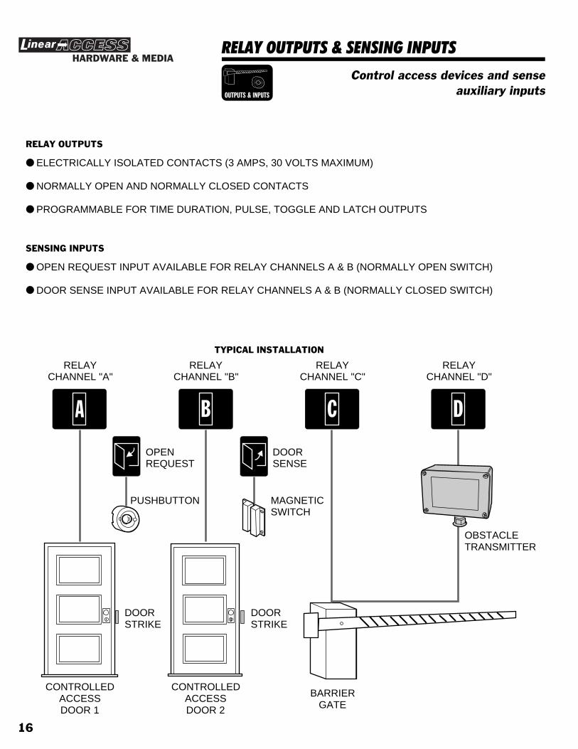
RELAY OUTPUTS & SENSING INPUTS
Control access devices and senseauxiliary inputs
HARDWARE & MEDIA
OUTPUTS & INPUTS
RELAY OUTPUTS
● ELECTRICALLY ISOLATED CONTACTS (3 AMPS, 30 VOLTS MAXIMUM)
● NORMALLY OPEN AND NORMALLY CLOSED CONTACTS
● PROGRAMMABLE FOR TIME DURATION, PULSE, TOGGLE AND LATCH OUTPUTS
SENSING INPUTS
● OPEN REQUEST INPUT AVAILABLE FOR RELAY CHANNELS A & B (NORMALLY OPEN SWITCH)
● DOOR SENSE INPUT AVAILABLE FOR RELAY CHANNELS A & B (NORMALLY CLOSED SWITCH)
B
RELAYCHANNEL "B"
C
RELAYCHANNEL "C"
D
RELAYCHANNEL "D"
A
RELAYCHANNEL "A"
OPENREQUEST
DOORSENSE
DOORSTRIKE
DOORSTRIKE
CONTROLLEDACCESSDOOR 1
CONTROLLEDACCESSDOOR 2
BARRIERGATE
OBSTACLETRANSMITTER
TYPICAL INSTALLATION
PUSHBUTTON MAGNETICSWITCH
16

RS-232 PORT
For printing event log, programmingand transferring memory between units
HARDWARE & MEDIARS-232
PORT
MODEL A2MMODEMCABLE
MODEL A2CCOMPUTERCABLE
MODEL A2PPRINTERCABLE
SERIALPRINTER
TERMINAL
PERSONALCOMPUTER
MODEM
SERIAL PRINTER
● P R I N T S R E A L - T I M E E V E N T L O G● P R I N T S S Y S T E M R E P O R T S● U S E M O D E L A 2 P C A B L E
COMPUTER TERMINAL
● D I S P L A Y S R E A L - T I M E E V E N T L O G● D I S P L A Y S S Y S T E M R E P O R T S● L O C A L L Y P R O G R A M A M / I I● U S E M O D E L A 2 C C A B L E
PERSONAL COMPUTER
● D I S P L A Y S R E A L - T I M E E V E N T L O G● D I S P L A Y S S Y S T E M R E P O R T S● L O C A L L Y P R O G R A M A M / I I● S T O R E A M / I I M E M O R Y T O D I S K● L O A D A M / I I M E M O R Y F R O M D I S K● U S E M O D E L A 2 C C A B L E
COMPUTER MODEM
● C O N N E C T S T O A M / I I R S - 2 3 2 P O R T● A N S W E R S C A L L S F R O M R E M O T E C O M P U T E R● R E M O T E L Y P R O G R A M A M / I I● R E M O T E L Y S T O R E A M / I I M E M O R Y T O D I S K● R E M O T E L Y L O A D A M / I I M E M O R Y F R O M D I S K● R E M O T E L Y D I S P L A Y S T O R E D E V E N T L O G● R E M O T E L Y D I S P L A Y S Y S T E M R E P O R T S● U S E M O D E L A 2 M C A B L E
MODEL A2AINTERCONNECTCABLE
AM/II INTERCONNECT
● C O N N E C T S T W O A M / I I U N I T S T O G E T H E R● T R A N S F E R M E M O R Y B E T W E E N U N I T S● U S E M O D E L A 2 A C A B L E
17

ACCESS OUT & NETWORK TERMINALS
For linking an AM/II to an externalaccess control panel and connecting
multiple AM/II’s together
HARDWARE & MEDIA
ACCESS OUT& NETWORK
EXPANSION MEMORY CARD
RADIO
DECODE
ACCESS GRANTED
READER KEYPAD
ACCESS OUT DATA
ACCESS IN DATA
ACCESS A
ACCESS B
ACCESS C
OBSTACLE
MAGIC WAND
ACCESS D
BO 1 O 1 O 1 BO 1 N.O. COM. N.C. N.O. COM. N.C. N.O. COM. N.C. N.O. COM. N.C.
EARTHGROUND
ACCESS OUT KEYPAD IN CHANNEL A CHANNEL B CHANNEL C CHANNEL DREADER IN
14 - 24 VAC12 - 35 VDCAC POWER
INPUTDC POWER
INPUTNETWORK
WARNING
RADIO
PERIPHERALS
RELAYS
EXTERNAL CONTROL
RS-232
OFF
ON
POWER
POWER
RESET
DISPLAYCONTRAST
SYSTEM
ACCESS OUT TERMINALS
● PASSES ACCESS OUT INFORMATION TO AN EXTERNAL ACCESS CONTROL SYSTEM
● SUPPORTS WIEGAND26 SECURAKEY31, AND SENTEX30DATA FORMATS
● EXTERNAL ACCESS PANEL CAN BE USED FOR VALIDATION OF PASS-THROUGH DATA FROM THE AM/II
● SIMPLE THREE-WIRE CONNECTION
NETWORK TERMINALS
● UP TO EIGHT AM/II UNITS CAN BE CONNECTED TOGETHER
● EVENT LOG IS SHARED BETWEEN THE NETWORKED UNITS
● SIMPLE TWO-WIRE RS-485 CONNECTION
EXPANSION MEMORY CARD
RADIO
DECODE
ACCESS GRANTED
READER KEYPAD
ACCESS OUT DATA
ACCESS IN DATA
ACCESS A
ACCESS B
ACCESS C
OBSTACLE
MAGIC WAND
ACCESS D
BO 1 O 1 O 1 BO 1 N.O. COM. N.C. N.O. COM. N.C. N.O. COM. N.C. N.O. COM. N.C.
EARTHGROUND
ACCESS OUT KEYPAD IN CHANNEL A CHANNEL B CHANNEL C CHANNEL DREADER IN
14 - 24 VAC12 - 35 VDCAC POWER
INPUTDC POWER
INPUTNETWORK
RADIO
PERIPHERALS
RELAYS
EXTERNAL CONTROL
RS-232
OFF
ON
POWER
POWER
RESET
DISPLAYCONTRAST
SYSTEM
EXPANSION MEMORY CARD
RADIO
DECODE
ACCESS GRANTED
READER KEYPAD
ACCESS OUT DATA
ACCESS IN DATA
ACCESS A
ACCESS B
ACCESS C
OBSTACLE
MAGIC WAND
ACCESS D
BO 1 O 1 O 1 BO 1 N.O. COM. N.C. N.O. COM. N.C. N.O. COM. N.C. N.O. COM. N.C.
EARTHGROUND
ACCESS OUT KEYPAD IN CHANNEL A CHANNEL B CHANNEL C CHANNEL DREADER IN14 - 24 VAC12 - 35 VDC
AC POWERINPUT
DC POWERINPUTNETWORK
RADIO
PERIPHERALS
RELAYS
EXTERNAL CONTROL
RS-232
OFF
ON
POWER
POWER
RESET
DISPLAYCONTRAST
SYSTEM
EXPANSION MEMORY CARD
RADIO
DECODE
ACCESS GRANTED
READER KEYPAD
ACCESS OUT DATA
ACCESS IN DATA
ACCESS A
ACCESS B
ACCESS C
OBSTACLE
MAGIC WAND
ACCESS D
BO 1 O 1 O 1 BO 1 N.O. COM. N.C. N.O. COM. N.C. N.O. COM. N.C. N.O. COM. N.C.
EARTHGROUND
ACCESS OUT KEYPAD IN CHANNEL A CHANNEL B CHANNEL C CHANNEL DREADER IN14 - 24 VAC12 - 35 VDC
INPUTINPUTNETWORK
RADIO
PERIPHERALS
RELAYS
EXTERNAL CONTROL
RS-232
OFF
ON
POWER
POWER
RESET
DISPLAYCONTRAST
SYSTEM
AC POWER DC POWER
MEMORY EXPANSION CARD
MEDIUM (64 K)
SMALL (16 K) LARGE (128 K)
X-LARGE (256 K)
WARNING
TURN THE POWER SWITCH OFF BEFORE INSTALLING ORREMOVING THIS MEMORY EXPANSION CARD
SEVEREELECTRICAL
DAMAGE
MEMORY EXPANSION CARD
MEDIUM (64 K)
SMALL (16 K) LARGE (128 K)
X-LARGE (256 K)
WARNING
TURN THE POWER SWITCH OFF BEFORE INSTALLING ORREMOVING THIS MEMORY EXPANSION CARD
SEVEREELECTRICAL
DAMAGE
MEMORY EXPANSION CARD
MEDIUM (64 K)
SMALL (16 K) LARGE (128 K)
X-LARGE (256 K)
WARNING
TURN THE POWER SWITCH OFF BEFORE INSTALLING ORREMOVING THIS MEMORY EXPANSION CARD
SEVEREELECTRICAL
DAMAGE
MEMORY EXPANSION CARD
MEDIUM (64 K)
SMALL (16 K) LARGE (128 K)
X-LARGE (256 K)
WARNING
TURN THE POWER SWITCH OFF BEFORE INSTALLING ORREMOVING THIS MEMORY EXPANSION CARD
SEVEREELECTRICAL
DAMAGE
18

MEMORY UTILITIES
For copying and transferring memorymodule data
HARDWARE & MEDIA
MEMORYUTILITIES
COPYING MEMORY DATA
● MEMORY MODULE INFORMATION CAN BE SENT TO AND RECEIVED FROM ANOTHER AM/II THROUGH THE RS-232 PORT USING THE MODEL A2A CABLE
SENDING AND RECEIVING MEMORY DATA
● MEMORY MODULE DATA CAN BE SENT AND RECEIVED THROUGH THE RS-232 PORT OVER THE PHONE LINE USING A MODEM WITH THE MODEL A2M CABLE
● MEMORY MODULE DATA CAN ALSO BE SENT AND RECEIVED THROUGH THE RS-232 PORT WITH A PERSONAL COMPUTER DIRECTLY CONNECTED TO THE AM/II USING THE MODEL A2C CABLE
RADIO
DECODE
ACCESS GRANTED
READER KEYPAD
ACCESS OUT DATA
ACCESS IN DATA
ACCESS A
ACCESS B
ACCESS C
OBSTACLE
MAGIC WAND
ACCESS D
BO 1 O 1 O 1 BO 1 N.O. COM. N.C. N.O. COM. N.C. N.O. COM. N.C. N.O. COM. N.C.
EARTHGROUND
ACCESS OUT KEYPAD IN CHANNEL A CHANNEL B CHANNEL C CHANNEL DREADER IN
14 - 24 VAC12 - 35 VDCAC POWER
INPUTDC POWER
INPUTNETWORK
RS-232
OFF
ON
POWER
POWER
RESET
DISPLAYCONTRAST
RADIO
DECODE
ACCESS GRANTED
READER KEYPAD
ACCESS OUT DATA
ACCESS IN DATA
ACCESS A
ACCESS B
ACCESS C
OBSTACLE
MAGIC WAND
ACCESS D
BO 1 O 1 O 1 BO 1 N.O. COM. N.C. N.O. COM. N.C. N.O. COM. N.C. N.O. COM. N.C.
EARTHGROUND
ACCESS OUT KEYPAD IN CHANNEL A CHANNEL B CHANNEL C CHANNEL DREADER IN 14 - 24 VAC12 - 35 VDC
AC POWERINPUT
DC POWERINPUTNETWORK
OFF
ON
POWER
RESET
DISPLAYCONTRAST
MODEL A2ACABLE
MODEM
PERSONAL COMPUTER
MODEL A2MCABLE
MODEL A2CCABLE
MEMORY EXPANSION CARD
MEDIUM (64 K)
SMALL (16 K) LARGE (128 K)
X-LARGE (256 K)
WARNING
TURN THE POWER SWITCH OFF BEFORE INSTALLING ORREMOVING THIS MEMORY EXPANSION CARD
SEVEREELECTRICAL
DAMAGE
MEMORY EXPANSION CARD
MEDIUM (64 K)
SMALL (16 K) LARGE (128 K)
X-LARGE (256 K)
WARNING
TURN THE POWER SWITCH OFF BEFORE INSTALLING ORREMOVING THIS MEMORY EXPANSION CARD
SEVEREELECTRICAL
DAMAGE
RADIO
DECODE
ACCESS GRANTED
READER KEYPAD
ACCESS OUT DATA
ACCESS IN DATA
ACCESS A
ACCESS B
ACCESS C
OBSTACLE
MAGIC WAND
ACCESS D
BO 1 O 1 O 1 BO 1 N.O. COM. N.C. N.O. COM. N.C. N.O. COM. N.C. N.O. COM. N.C.
EARTHGROUND
ACCESS OUT KEYPAD IN CHANNEL A CHANNEL B CHANNEL C CHANNEL DREADER IN
14 - 24 VAC12 - 35 VDCAC POWER
INPUTDC POWER
INPUTNETWORK
RS-232
OFF
ON
POWER
POWER
RESET
DISPLAYCONTRAST
MEMORY EXPANSION CARD
MEDIUM (64 K)
SMALL (16 K) LARGE (128 K)
X-LARGE (256 K)
WARNING
TURN THE POWER SWITCH OFF BEFORE INSTALLING ORREMOVING THIS MEMORY EXPANSION CARD
SEVEREELECTRICAL
DAMAGE
19

PRE-INSTALLATION PLANNINGBefore beginning, take time to plan the installation.✶ Make a sketch of the installation floor plan showing all
controlled access points.✶ Select a good location to mount the AM/II.✶ Determine a good location for the antenna.✶ Select locations for the remote accessory devices (keypads,
card readers, remote receivers, proximity receivers).✶ Research possible places for wire runs to accessories and
access devices.
INSTALLATION OUTLINEThe following outline is intended to guide you through theinstallation of an AM/II system.
1. Unpack the system. Identify the system components(transformer, antenna, etc.).
2. Plan the installation by creating an installation diagram.
3. Mount the AM/II (in an optional cabinet if required).
4. Connect the antenna.
5. Install any remote accessory devices.
6. Wire connections to the AM/II terminals.
A. Install a ground stake and run the ground wire or usea cold water pipe as earth ground for the AM/II.
B. Connect relay outputs to the access device(s) to becontrolled.
C. Turn AM/II POWER switch off and connect theplug-in transformer or connect the AM/II to a14-24 VAC or 12-35 VDC auxiliary power supply.
D. Turn the POWER switch on. The green POWERindicator should light.
E. Adjust the display contrast as desired.7. Program the system.
8. Test the system.
9. Adjust the red RADIO RANGE knob to limit the maximum rangeof the receiver.
LOBBY
AC
CO
UN
TIN
G
SERVICE
SALES
PRESIDENT
V.P.V.P.
SALES PURCH.
ENGINEERING
BATH BATH
CO
MP
UT
ER
RO
OM
STOR.
COPIERAREA
CHIEFENG.
LAB
20

WIRELESS INSTALLATION TIPSSignals Through Construction MaterialsWhen installing any wireless system, certain limitations mustbe considered. Low power wireless UHF transmitter signals willnot broadcast equally through all types of constructionmaterials. The AM/II contains a receiver that should allowreception of the transmitters in almost all locations. Refer tofigure showing approximate signal strength that will occur withdifferent types of building materials.
Transmitters in VehiclesThe radio range of a transmitter will also be affected when thetransmitter is located in a vehicle. Depending on the locationof the transmitter (on the visor, on the dash, in the centerconsole) the range will vary. Most of the signal strengthchanges are related to the amount of metal in close proximityto the transmitter. If a transmitter is clipped to the top of thedriver’s sun visor, with the visor flipped up, placing thetransmitter between the metal roof and the metal reinforcedvisor, the transmitters range will be reduced.
PRE-INSTALLATIONUnpacking the SystemThe basic AM/II system package includes the followingaccessories:✶ Plug-in Transformer. Provides low voltage power to the
access control panel.✶ Mounting Screws. Used to mount the AM/II inside the
cabinet.
Installing the Memory ModuleFour sizes of memory modules are available for the AM/II:✶ SMALL (16K) MEMORY✶ MEDIUM (64K) MEMORY✶ LARGE (128K) MEMORY✶ X-LARGE (256K) MEMORYOne of the memory modules must be installed for the AM/II tofunction.✘ CAUTION! Be sure the AM/II is disconnected from power
or that the AM/II’s POWER switch is off before removingof replacing the memory module.
STEP 1 With the system power off, plug the memory moduleinto the AM/II.
STEP 2 Secure the memory module with two screws.
90% - 100%OF FULL POWER
65% - 95%OF FULL POWER
10% - 70%OF FULL POWER
WALLBOARD ANDWOOD STUDS
CONCRETE WITH STEELREINFORCEMENT OR
METAL LATH AND PLASTER
LIGHT CONCRETEOR BRICK
AM/II UNIT WITH MEMORY INSTALLED
PLUG-INTRANSFORMER
CASE MOUNTINGSCREWS
RADIO
DECODE
ACCESS GRANTED
READER KEYPAD
ACCESS OUT DATA
NETWORK DATA
ACCESS A
ACCESS B
ACCESS C
OBSTACLE
MAGIC WAND
ACCESS D
BO 1 O 1 O 1 BO 1 N.O. COM. N.C. N.O. COM. N.C. N.O. COM. N.C. N.O. COM. N.C.
EARTHGROUND
ACCESS OUT KEYPAD IN CHANNEL A CHANNEL B CHANNEL C CHANNEL DREADER IN 14 - 24 VAC12 - 35 VDC
AC POWERINPUT
DC POWERINPUTNETWORK
OFF
ON
POWER
RESET
DISPLAYCONTRAST
MEMORY EXPANSION CARD
MEDIUM (64 K)
SMALL (16 K) LARGE (128 K)
X-LARGE (256 K)
WARNING
TURN THE POWER SWITCH OFF BEFORE INSTALLING ORREMOVING THIS MEMORY EXPANSION CARD
SEVEREELECTRICAL
DAMAGE
INSTALL MEMORYMODULE
21

MOUNT UNITThe AM/II can be mounted indoors directly to a wall or in theModel CAB-1 indoor cabinet. For outdoor mounting, the ModelCAB-2 weather resistant cabinet is recommended. The twocabinets both provide some security for the unit.Each cabinet has wiring knockouts for connection to wiringconduit.
STEP 1 Decide on a good location (near power and goodwiring access) to mount the AM/II. It should be in asecure location. The mounting area should bebetween -22 and +149 degrees Fahrenheityear-around.
STEP 2 If a cabinet is used, punch out the conduit knockoutsas required for the installation. Attach the cabinet tothe wall with the appropriate fasteners.
STEP 3 Secure the AM/II with three screws.
DIRECT MOUNTING
FOR INDOOR INSTALLATIONSTHE AM/II CAN BE MOUNTEDDIRECTLY USING THREESCREWS AND APPROPRIATESCREW ANCHORS
DRIVE FOUR SCREWS INTOWALL AT THESE LOCATIONS(LEAVE SCREW HEAD 1/8" OUTFROM WALL)
USE PLASTIC SCREWANCHORS IF REQUIRED
HANG CABINET ON SCREWS
DIRLL A HOLE AND DRIVE A FIFTH SCREWINTO THE HOLE TOLOCK CABINET TO WALL
8"
8-3/4"
CAB-1 MOUNTING
MOUNT AM/II UNIT INTOCABINET WITH THREESCREWS SUPPLIED
EXPANSION MEMORY CARD
RADIO
DECODE
ACCESS GRANTED
READER KEYPAD
ACCESS OUT DATA
ACCESS IN DATA
ACCESS A
ACCESS B
ACCESS C
OBSTACLE
MAGIC WAND
ACCESS D
BO 1 O 1 O 1 BO 1 N.O. COM. N.C. N.O. COM. N.C. N.O. COM. N.C. N.O. COM. N.C.
EARTHGROUND
ACCESS OUT KEYPAD IN CHANNEL A CHANNEL B CHANNEL C CHANNEL DREADER IN14 - 24 VAC12 - 35 VDC
AC POWERINPUT
DC POWERINPUTNETWORK
OK
WARNINGSEVERE
ELECTRICALDAMAGE
T U R N T H E P O W E R S W I T C H O F F B E F O R E I N S T A L L I N G O RR E M O V I N G T H I S M E M O R Y E X P A N S I O N C A R D
MEMORY EXPANSION CARD
RADIO
PERIPHERALS
RELAYS
EXTERNAL CONTROL
RS-232
OFF
ON
POWER
POWER
RESET
DISPLAYCONTRAST
SYSTEM
SMALL MEDIUM LARGE
PUNCH OUT REQUIREDCONDUIT CONNECTIONKNOCKOUTS FOR ANTENNA,POWER, GROUND AND SIGNALS
CAB-2 MOUNTING
CAB-2 MOUNTS WITH FOURSCREWS AT THESE LOCATIONS
USE PLASTIC SCREWANCHORS OR CONCRETEWEDGE ANCHORS
9"
9"
PUNCH OUT REQUIREDCONDUIT CONNECTIONKNOCKOUTS FOR ANTENNA,POWER, GROUND AND SIGNALS
EXPANSION MEMORY CARD
RADIO
DECODE
ACCESS GRANTED
READER KEYPAD
ACCESS OUT DATA
ACCESS IN DATA
ACCESS A
ACCESS B
ACCESS C
OBSTACLE
MAGIC WAND
ACCESS D
BO 1 O 1 O 1 BO 1 N.O. COM. N.C. N.O. COM. N.C. N.O. COM. N.C. N.O. COM. N.C.
EARTHGROUND
ACCESS OUT KEYPAD IN CHANNEL A CHANNEL B CHANNEL C CHANNEL DREADER IN14 - 24 VAC12 - 35 VDC
AC POWERINPUT
DC POWERINPUTNETWORK
OK
WARNINGSEVERE
ELECTRICALDAMAGE
T U R N T H E P O W E R S W I T C H O F F B E F O R E I N S T A L L I N G O RR E M O V I N G T H I S M E M O R Y E X P A N S I O N C A R D
MEMORY EXPANSION CARD
RADIO
PERIPHERALS
RELAYS
EXTERNAL CONTROL
RS-232
OFF
ON
POWER
POWER
RESET
DISPLAYCONTRAST
SYSTEM
SMALL MEDIUM LARGE
MOUNT AM/II UNIT INTOCABINET WITH THREESCREWS SUPPLIED
22

EARTH GROUND & POWER CONNECTIONSEarth GroundFor the best ground, use size 14 gauge solid wire or larger toconnect the EARTH GROUND terminal to an 8-foot copperground rod. Locate the ground rod next to the Power andTelephone company rods and bond the rods together with anew clamp. Do not disturb the clamps installed by thePower or Telephone Company.Alternately, connect the EARTH GROUND terminal to a coldwater pipe or to the GND terminal on the AC transformer.
PowerThe AM/II is powered by a 16.5 Volt, 20 VA to 50 VA, internallyfused, UL listed, Class 2 transformer. This transformer isincluded with the AM/II system pack.The system can alternately be powered from a 12-35 VDC or14-24 VAC auxiliary power supply. Refer to the chart below forselecting wire size for the distance to the power source.Typically DC power is used when battery backed-upuninterruptable operation is required. The externally chargedbattery must be capable of supplying the power requirementsof the AM/II and it’s complement of devices.✘ WARNING! Never short the terminals of the transformer
together. This will cause the internal fuse to blow. Thetransformer must be connected to a 120 VAC 60 Hzunswitched (24 hour) power outlet not controlled by awall switch.
STEP 1 Be sure that the AM/II POWER switch is off.STEP 2 Connect the transformer to the AC terminals or
connect the AM/II to the operator’s auxiliary poweroutput.
✘ WARNING! Do not connect both AC and DC power.STEP 3 If used, plug transformer into AC outlet and secure
with case screw (if provided).☞ NOTE: Never power door strikes or other high current
magnetic devices from the same power source as the AM/II.
AM/IIEARTHGROUNDTERMINAL
AM/II & POWER CO.GROUND STAKESBONDED TOGETHER
14 GASOLID
DO NOTDISTURBPOWER CO.GROUND!
A COLD WATER PIPEOR THE AC TRANSFORMERGND TERMINAL MAY ALSOBE USED FOR EARTH GROUND
POWEROFF
ON
EARTHGROUND
14 - 24 VAC12 - 35 VDC
AC POWERINPUT
DC POWERINPUT
TRANSFORMER16 VAC, 20 VA
AC
AC
GND
CONNECT EITHERAC OR DC POWER
NOT BOTH!
POWER WIRE DISTANCE MINIMUM WIRE SIZE
1-50 FEET 18 AWG
51-150 FEET 16 AWG
151-250 FEET 14 AWG
251-500 FEET 12 AWG
23

REMOTE DEVICE WIRING REQUIREMENTSCable TypeEach remote device requires a 6-wire connection to the AM/II.Depending on the distance of the cable run, two different typesof cable are recommended.✶ For cable distance up to 300 feet, use BELDEN 9931
(24 AWG).✶ For cable distance up to 500 feet, use WEICO 9405
(20 AWG).
Load NumberEach hardwired remote accessory device has been assigneda “load number”. Homerun wiring is recommended foraccessories, although multiple accessories can be wired on thesame cable run if the following formulas are used.✶ For cable distance up to 300 feet:
CABLE RUN IN FEET x LOAD UNITS = 3,000 OR LESS✶ For cable distance up to 500 feet:
CABLE RUN IN FEET x LOAD UNITS = 10,000 OR LESS
REMOTE DEVICE LOAD NUMBER
AM-KP 9
AM-RRR 4
AM-CRI 25
AM-RPR 4
24

ANTENNA HOOK-UPIf using a remote antenna, construct the antenna kit asdescribed in its instructions. Mount the antenna as high aspossible. Connect the coax lead to the AM/II antennaconnector. Up to 25 feet of coax cable may be used to connectthe antenna.☞ NOTE: Mount the antenna at least 10 feet from the AM/II
control.
REMOTE RADIO RECEIVER CONNECTIONSThe Model AM-RRR remote radio receiver can be used toextend the radio range and remote the radio input of the AM/II.Use the AM-RRR with its local whip antenna or with theEXA-1000 or EXA-2000 remote antennas.The receiver is connected to the READER IN terminals on theAM/II. Follow the instructions supplied with the remote receiverand the hook-up diagram shown.The DEVICE ADDRESS SELECTOR switch in the unit selectsthe device address. It must be set from 1-6, and be differentfrom any other remote accessory device.
ANTENNAMOUNTEDAS HIGHAS POSSIBLE
CO-AX TORECEIVER
U-BOLT
2" MAXDIA.
ATTIC MOUNTING POST MOUNTING
(RE
D)
(BLK
)
(GR
N)
(WH
T)
(BLU
)
(OR
G/Y
EL)
PW
RG
ND
DA
T1
DA
T0
DV
AL
CLK
RADIORANGECONTROL
RADIOSIGNALINDICATOR
ACCESS GRANTEDINDICATORRED = POWERGREEN = ACCESS
DEVICEADDRESSSELECTOR
ANTENNACONNECTOR
EXA-2000DIRECTIONALANTENNAMOUNTEDON WOODPOST
25

REMOTE KEYPAD CONNECTIONSThe Model AM-KP access control keypads can be used formanual code entry for the AM/II. The keypad can be mountedon a pedestal or directly to a wall.The keypad is connected to the KEYPAD IN terminals on theAM/II. Follow the instructions supplied with the keypad and thehook-up diagram shown.The DEVICE ADDRESS SELECTOR switch in the unit selectsthe device address. It must be set from 1-6, and be differentfrom any other remote accessory device.
REMOTE PROXIMITY RECEIVERThe Model AM-RPR proximity receiver can be used forultra-short range transmitter reception at access portals. Thetransmitter will have to be activated right next to this receiverto activate it. The receiver is mounted in a single-gang plasticoutlet box.The receiver is connected to the READER IN terminals on theAM/II. Follow the instructions supplied with the proximityreceiver and the hook-up diagram shown.The DEVICE ADDRESS SELECTOR switch in the unit selectsthe device address. It must be set from 1-6, and be differentfrom any other remote accessory device.
*
5 6
7 8 9
0 #
1 2 3
4
FOR LOCAL POWER,DISCONNECT RED WIRE ANDCONNECT EXTERNAL 12 VDC
POWER SUPPLY TO PWR & GND
BO 1 O O
O1 1
1 B
BO 1
PWR GND DAT1 DAT0 DVAL CLKG
RN
BLK
WH
T
BLU
OR
G/Y
EL
RED
PWR
GND
DAT1
DAT0
DVAL
CLK
AM/II TERMINALS
B
AM-RPR
26

CARD READER INTERFACEThe Model AM-CRI card reader interface can support two cardreaders. It would be located between the card readers and theAM/II, usually near the card readers.The card reader is connected to the READER IN terminals onthe AM/II. Follow the instructions supplied with the keypad andthe hook-up diagram.Two rotary switches in the unit selects the device address foreach card reader. They must be set to different numbers from1-6, and also be different from any other remote accessorydevice.
CONTROL INPUTSOpen RequestThe open request terminals for relays A & B are available forconnection to an external switch. When the switch closes toground, if the relay channel is not locked closed, the relay willactivate.Common uses would be with a knox box, pushbutton, or keylock where someone would need to open the access portalfrom inside the controlled area.
Door SenseThe door sense terminals for relays A & B are used withnormally closed door contacts. The contacts monitor theposition of the access door. When the door opens, the contactsopen.Door sensing is required to use the door ajar and door relockfeatures. Door sensing can detect when a door is propped openand cause an alarm relay to activate when the door is openlonger than the door ajar time. Door sensing also detects whenthe door is closed, deactivating the control relay the momentthe door closes.
AM-CRI
PWR
GND
DAT1
DATO
DVAL
CLK(RED)
(BLK)
(GRN)
(WHT)
(BLU)
(ORG/YEL)
CARD READER "B"DEVICE ADDRESS SELECTOR
(1-6)
MAG LOCK
OPEN REQUESTPUSHBUTTON
N.O. COM. N.C. N.O. COM. N.C.
CHANNEL A CHANNEL B
CHANNEL "A"OPEN REQUESTPUSHBUTTON
CHANNEL "B"OPEN REQUESTPUSHBUTTON
AM/IITERMINALS
CONTACT OPENS WHENDOOR OPENS AND MOVESMAGNET AWAY FROM SWITCH N.O. COM. N.C. N.O. COM. N.C.
CHANNEL A CHANNEL B
CHANNEL "A"DOOR SENSECONTACT
CHANNEL "B"DOOR SENSECONTACT
(DOORCLOSED)
(DOOROPEN)
AM/IITERMINALS
27
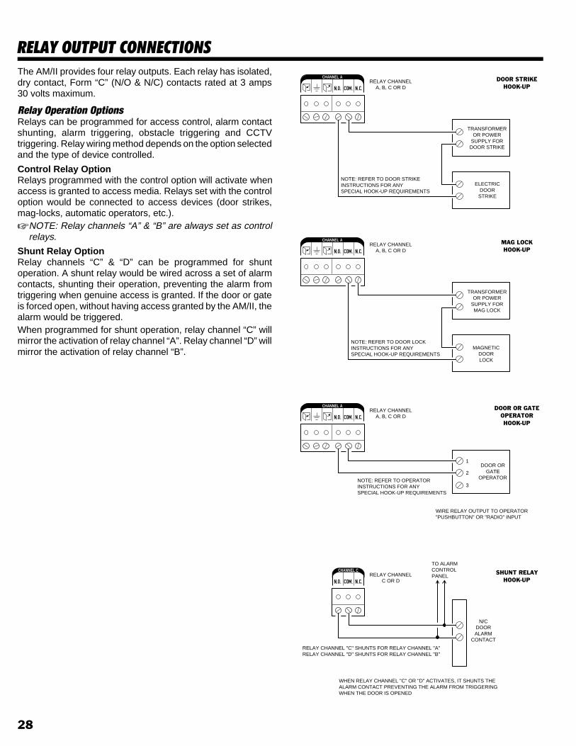
RELAY OUTPUT CONNECTIONSThe AM/II provides four relay outputs. Each relay has isolated,dry contact, Form “C” (N/O & N/C) contacts rated at 3 amps30 volts maximum.
Relay Operation OptionsRelays can be programmed for access control, alarm contactshunting, alarm triggering, obstacle triggering and CCTVtriggering. Relay wiring method depends on the option selectedand the type of device controlled.
Control Relay OptionRelays programmed with the control option will activate whenaccess is granted to access media. Relays set with the controloption would be connected to access devices (door strikes,mag-locks, automatic operators, etc.).☞ NOTE: Relay channels “A” & “B” are always set as control
relays.
Shunt Relay OptionRelay channels “C” & “D” can be programmed for shuntoperation. A shunt relay would be wired across a set of alarmcontacts, shunting their operation, preventing the alarm fromtriggering when genuine access is granted. If the door or gateis forced open, without having access granted by the AM/II, thealarm would be triggered.When programmed for shunt operation, relay channel “C” willmirror the activation of relay channel “A”. Relay channel “D” willmirror the activation of relay channel “B”.
ELECTRICDOOR
STRIKE
N.O. COM. N.C.
CHANNEL ARELAY CHANNEL
A, B, C OR D
DOOR STRIKEHOOK-UP
TRANSFORMEROR POWER
SUPPLY FORDOOR STRIKE
NOTE: REFER TO DOOR STRIKEINSTRUCTIONS FOR ANYSPECIAL HOOK-UP REQUIREMENTS
MAGNETICDOORLOCK
N.O. COM. N.C.
CHANNEL ARELAY CHANNEL
A, B, C OR D
MAG LOCKHOOK-UP
TRANSFORMEROR POWER
SUPPLY FORMAG LOCK
NOTE: REFER TO DOOR LOCKINSTRUCTIONS FOR ANYSPECIAL HOOK-UP REQUIREMENTS
N.O. COM. N.C.
CHANNEL ARELAY CHANNEL
A, B, C OR D
DOOR OR GATEOPERATORHOOK-UP
DOOR ORGATE
OPERATOR
1
2
3
WIRE RELAY OUTPUT TO OPERATOR"PUSHBUTTON" OR "RADIO" INPUT
NOTE: REFER TO OPERATORINSTRUCTIONS FOR ANYSPECIAL HOOK-UP REQUIREMENTS
N.O. COM. N.C.RELAY CHANNEL
C OR D
SHUNT RELAYHOOK-UP
N/CDOORALARM
CONTACT
CHANNEL C
RELAY CHANNEL "C" SHUNTS FOR RELAY CHANNEL "A"RELAY CHANNEL "D" SHUNTS FOR RELAY CHANNEL "B"
WHEN RELAY CHANNEL "C" OR "D" ACTIVATES, IT SHUNTS THE ALARM CONTACT PREVENTING THE ALARM FROM TRIGGERINGWHEN THE DOOR IS OPENED
TO ALARMCONTROLPANEL
28

Alarm Relay OptionRelay channels “C” & “D” can be programmed for alarmoperation. An alarm relay would be wired to a noisemaker orto the loop input of an alarm control panel.Relay channel “C” can function as an alarm relay for relaychannel “A”. Relay channel “D” can function as an alarm relayfor relay channel “B”. The door sense input must be wired forrelay channel “A” and/or “B” for the alarm relay function to work.If door “A” or “B” is held open longer than the Door Ajar Timetime programmed, the alarm relay for the appropriate relaychannel will activate.
Obstacle Relay OptionRelay channels “C” & “D” can function as obstacle relays whenModel MGT obstacle transmitters are used. Relay channel “C”activates for MGT obstacle transmitter #1, relay channel “D”activates for MGT obstacle transmitter #2.Obstacle relays are used to trigger obstacle inputs onautomatic door and gate operators. Triggering the obstacleinput will reverse or stop the operator.
CCTV Relay OptionRelay channels “C” & “D” can function as CCTV relays. Theycan be used only when a Model AE-1 or AE-2 telephone entrymodule is installed with the AM/II.When a telephone connection is made to a directory party, theycan press the “5" digit on their telephone to activate the CCTVrelay. A CCTV camera would activate to send a picture of theentry area to the directory party.
N.O. COM. N.C.RELAY CHANNEL
C OR D
ALARM RELAYHOOK-UP
ALARMCONTROL
PANEL
CHANNEL C
RELAY CHANNEL "C" ALARMS FOR RELAY CHANNEL "A"RELAY CHANNEL "D" ALARMS FOR RELAY CHANNEL "B"
TRANSFORMEROR POWER
SUPPLY FORNOISEMAKER
NOISEMAKER
N.O. COM. N.C.
CHANNEL C
RELAY CHANNELC OR D
ALARM RELAY ACTIVATES WHEN DOOR IS OPEN LONGER THAN DOOR AJAR TIME OR WHEN DOOR IS FORCED OPEN WITHOUT VALID ACCESS BEING GRANTED
GATEOPERATOROBSTACLE
INPUT
N.O. COM. N.C.RELAY CHANNEL
C OR D
OBSTACLE RELAYHOOK-UP
CHANNEL C
RELAY CHANNEL "C" ACTIVATES FOR OBSTACLE TX #1RELAY CHANNEL "D" ACTIVATES FOR OBSTACLE TX #2
WHEN RELAY ACTIVATES, IT TRIGGERS THE OBSTACLE INPUT OF THE OPERATOR, STOPPING OR REVERSING THE OPERATOR
WIRE RELAY OUTPUT TO OPERATOROBSTACLE INPUT
NOTE: REFER TO OPERATORINSTRUCTIONS FOR ANYSPECIAL HOOK-UP REQUIREMENTS
CCTVCAMERA
IRIS ENABLE
N.O. COM. N.C.RELAY CHANNEL
C OR D
CCTV RELAYHOOK-UP
CHANNEL C
WHEN RELAY ACTIVATES, IT ALLOWS THE CAMERA TO SEND VIDEO TO THE DIRECTORY PARTY'S MONITOR
WIRE RELAY OUTPUT TO CAMERAIRIS ENABLE OR VIDEO ENABLE INPUT
NOTE: REFER TO CCTV CAMERAINSTRUCTIONS FOR ANYSPECIAL HOOK-UP REQUIREMENTS
29

RS-232 PORT CONNECTIONSThe AM/II RS-232 port can be used to connect to a serial inputline printer, a personal computer, modem or data terminal.
Printer Connections☞ NOTE: The installation of a printer is optional. The AM/II may
be used without a printer if activity logging is not required.The AM/II can connect to virtually any standard personalcomputer printer that accepts a 9600 baud serial RS-232 input.Connecting a printer to the AM/II allows for a printed copy ofeach transmitter activation showing the transmitter number,time and date of activation as well as the various systemreports. Use the Model A2P cable to connect the AM/II to aprinter.Personal computer printers contain switches for setting theprinter’s data format and options. The printer’s switches mustbe set correctly to match the output of the AM/II before theprinter will function properly. Refer to the specific printer’sinstruction manual for the location and possible settings of theprinter’s switches.The printer may have additional options that may or may notbe useful with the AM/II.The printer options that must be set are:✶ Baud Rate 9600✶ 8 Data Bits✶ No Parity✶ 1 Stop Bit✶ No Auto Line Feed after Carriage Return✶ X-ON/X-OFF Data Flow Control
2
3
7
20
8-PIN
2
1
8
6
RD
TD
GND
CTS
DB-25 SIGNALTD
RD
GND
DTR
SIGNAL
AM/IIPRINTER
MALEDB-25
8-PINMODULAR
PIN 1
A2P CABLE
RADIO
DECODE
ACCESS GRANTED
READER KEYPAD
ACCESS OUT DATA
ACCESS IN DATA
ACCESS A
ACCESS B
ACCESS C
OBSTACLE
MAGIC WAND
ACCESS D
BO 1 O 1 O 1 BO 1 N.O. COM. N.C. N.O. COM. N.C. N.O. COM. N.C. N.O. COM. N.C.
EARTHGROUND
ACCESS OUT KEYPAD IN CHANNEL A CHANNEL B CHANNEL C CHANNEL DREADER IN14 - 24 VAC12 - 35 VDC
AC POWERINPUT
DC POWERINPUTNETWORK
OFF
ON
POWER
RESET
DISPLAYCONTRAST
MEMORY EXPANSION CARD
MEDIUM (64 K)
SMALL (16 K) LARGE (128 K)
X-LARGE (256 K)
WARNING
TURN THE POWER SWITCH OFF BEFORE INSTALLING ORREMOVING THIS MEMORY EXPANSION CARD
SEVEREELECTRICAL
DAMAGE
MODEL A2CCABLE
SAMPLE REAL-TIME EVENT PRINTOUT
10:52:42 06/20/95 0:0 sTx[00001] ->{A} AM/II Unit #110:52:42 06/20/95 0:2 Crd[01470] ->{D} Front Door Card Reader10:54:14 06/20/95 0:0 sTx[00003] ->{A} AM/II Unit #110:54:21 06/20/95 0:1 Kpd[2003] ->{C} Front Gate Keypad10:54:28 06/20/95 0:0 sTx[00002] ->{A} AM/II Unit #1
REAL-TIME EVENT LOG PRINTS EACH EVENT AS IT HAPPENS
TOP LINE OF EVENT SHOWS:
TIME & DATE
NETWORK ADDRESS : REMOTE DEVICE ADDRESS
MEDIA TYPE & ID#
DIRECTION OF ENTRY & RELAY LETTER
Event Log Report Jun 22, 1995 09:56:39 Page 001Installation: South Hills Apartments AM/II Unit #1
08:55:35 06/22/95 0:0 sTx[00003] ->{B} Unit #1
08:51:21 06/22/95 0:2 Crd[01470] ->{B} Front Door Card Reader
08:45:49 06/22/95 0:0 sTx[00001] ->{A} Unit #1
12:28:42 06/20/95 0:0 Obs[1] Obstacle Txmtr Trouble
11:02:42 06/20/95 0:0 Exit Program Mode11:02:42 06/20/95 0:0 Program Mode Timed Out
SAMPLE STORED EVENT LOG
STORED EVENT LOG SHOWS ALL EVENTS FROM MOST RECENT TO OLDEST STORED EVENT
BOTTOM LINE OF EVENT SHOWS: DEVICE NAME
PIN 1 PIN 2 PIN 3 PIN 4 PIN 5 PIN 6 PIN 7 PIN 8
SENDDATA
RECIEVEDATA
REQUESTTO SEND
N/C N/C CLEARTO SEND
N/C GROUND
8-PIN MODULARPLUG PINOUT
30

Personal Computer and Data Terminal Connections☞ NOTE: The installation of a personal computer (PC) or data
terminal for event logging and system programming isoptional, but recommended. Programming the AM/II is mucheasier, especially when using names, with a PC or dataterminal.
The AM/II can connect to virtually any PC’s serial port. Use theModel A2C-DB25 (25-pin) or A2C-DB9 (9-pin) cable to connectthe AM/II to a computer.When using a data terminal, connecting the cable and settingthe terminal port options is all that’s required. When using aPC, a communications program (AccessBase, AccountManager, Windows Terminal, Procomm, Quick Link,BitComm, etc.) must be used to communicate with the AM/II.The computer’s software will have settings for the PC’s portoptions. The software port options must be set correctly tomatch the output of the AM/II before the PC software willfunction properly. Refer to the specific software’s instructionsfor details on how to set the port options.The serial port (COM port) options that must be set are:✶ Baud Rate 9600✶ 8 Data Bits✶ No Parity✶ 1 Stop Bit✶ X-ON/X-OFF Data Flow ControlSetting the AM/II RS-232 port output to the “PRINTER” optionwill show the ongoing event log on the computer screen.Setting the AM/II RS-232 port output to the “TERMINAL” optionwill allow the computer to access the AM/II just like thekeyboard on the AM/II. The only keyboard differences whenusing a PC or terminal to access the AM/II are:✶ The ENTER key equals the AM/II’s OK key.✶ The ESCAPE (Esc) key is similar the AM/II’s * (star) key.
Press ESCAPE twice to enter program mode, once to jumpback to the main menu.
✶ The A-Z & 0-9 keys are used for character inputs.✶ Hold the CONTROL (Ctrl) key and press “Z” to exit
programming.
Modem Connections☞ NOTE: The installation of a modem is optional. It will allow
remote programming of the AM/II.The AM/II can connect to most personal computer externalmodems. Use the Model A2M cable to connect the AM/II to amodem. Connection to a modem allows you to call the AM/IIover the telephone with a personal computer and anothermodem. All of the same programming functions that can beperformed locally can be made remotely, off-site. Systemreports and the event log can be retrieved remotely.
2
3
7
20
8-PIN
2
1
8
6
RD
TD
GND
CTS
DB-25 SIGNALTD
RD
GND
DTR
SIGNAL
AM/IICOMPUTER
FEMALEDB-25
PIN 1
8-PINMODULAR
A2C-DB25 CABLE
RADIO
DECODE
ACCESS GRANTED
READER KEYPAD
ACCESS OUT DATA
NETWORK DATA
ACCESS A
ACCESS B
ACCESS C
OBSTACLE
MAGIC WAND
ACCESS D
BO 1 O 1 O 1 BO 1 N.O. COM. N.C. N.O. COM. N.C. N.O. COM. N.C. N.O. COM. N.C.
EARTHGROUND
ACCESS OUT KEYPAD IN CHANNEL A CHANNEL B CHANNEL C CHANNEL DREADER IN14 - 24 VAC12 - 35 VDC
AC POWERINPUT
DC POWERINPUTNETWORK
OFF
ON
POWER
RESET
DISPLAYCONTRAST
MEMORY EXPANSION CARD
MEDIUM (64 K)
SMALL (16 K) LARGE (128 K)
X-LARGE (256 K)
WARNING
TURN THE POWER SWITCH OFF BEFORE INSTALLING ORREMOVING THIS MEMORY EXPANSION CARD
SEVEREELECTRICAL
DAMAGE
MODEL A2CCABLE
3
2
7
5
4
8-PIN
2
1
8
6
3
RD
TD
GND
CTS
RTS
DB-25 SIGNAL
RD
TD
GND
CTS
RTS
SIGNAL
AM/IIMODEM
MALEDB-25
8-PINMODULAR
PIN 1
A2M CABLE
FEMALEDB-9
PIN 1
8-PINMODULAR
3
2
5
4
6
8
7
8-PIN
2
1
8
6
A2C-DB9 CABLE
RD
TD
GND
CTS
DB-9 SIGNALTD
RD
GND
DTR
DSR
CTS
RTS
SIGNAL
AM/IICOMPUTER
31

ACCESS OUT CONNECTIONSRadio control can be added easily to Sentex Infinity and othersystems. The AM/II can output the Sentex30, SecuraKey31,and Wiegand26 data formats through its ACCESS OUTterminals.When connected, the AM/II output simulates a card readerinput to the external access control panel. A few programmingoptions must be set in the AM/II to configure the output to matchthe access control panel.☞ NOTE: Connection to an external access control panel is
optional.
O 1
ACCESS OUT
TB4
TB6
LED AA RDR 1A RDR 0+5 VDCGND
LED BB RDR 1B RDR 0+5 VDCGND
SENTEXINFINITYSYSTEM
3-CONDUCTORSHIELDED
CABLE
OPTIONAL2-DEVICEHOOKUP
USE BELDEN TYPE 9925 CABLEOR EQUIVALENT
MAXIMUM WIRE RUNDISTANCE: 500 FEET
RADIO
DECODE
ACCESS GRANTED
READER KEYPAD
ACCESS OUT DATA
ACCESS IN DATA
ACCESS A
ACCESS B
ACCESS C
OBSTACLE
MAGIC WAND
ACCESS D
BO 1 O 1 O 1 BO 1 N.O. COM. N.C. N.O. COM. N.C. N.O. COM. N.C. N.O. COM. N.C.
EARTHGROUND
ACCESS OUT KEYPAD IN CHANNEL A CHANNEL B CHANNEL C CHANNEL DREADER IN14 - 24 VAC12 - 35 VDC
AC POWERINPUT
DC POWERINPUTNETWORK
OFF
ON
POWER
RESET
DISPLAYCONTRAST
MEMORY EXPANSION CARD
MEDIUM (64 K)
SMALL (16 K) LARGE (128 K)
X-LARGE (256 K)
WARNING
TURN THE POWER SWITCH OFF BEFORE INSTALLING ORREMOVING THIS MEMORY EXPANSION CARD
SEVEREELECTRICAL
DAMAGE
32

NETWORK CONNECTIONSUp to eight AM/II’s can be networked together allowinginformation sharing between the units. A common event log isretained for all of the networked units.Each unit is interconnected with a two-wire RS-485 connectionto the NETWORK terminals. Belden Type 9925 shielded cableis recommended for network connections.
RADIO
DECODE
ACCESS GRANTED
READER KEYPAD
ACCESS OUT DATA
ACCESS IN DATA
ACCESS A
ACCESS B
ACCESS C
OBSTACLE
MAGIC WAND
ACCESS D
BO 1 O 1 O 1 BO 1 N.O. COM. N.C. N.O. COM. N.C. N.O. COM. N.C. N.O. COM. N.C.
EARTHGROUND
ACCESS OUT KEYPAD IN CHANNEL A CHANNEL B CHANNEL C CHANNEL DREADER IN
14 - 24 VAC12 - 35 VDCAC POWER
INPUTDC POWER
INPUTNETWORK
OFF
ON
POWER
RESET
DISPLAYCONTRAST
MEMORY EXPANSION CARD
MEDIUM (64 K)
SMALL (16 K) LARGE (128 K)
X-LARGE (256 K)
WARNING
TURN THE POWER SWITCH OFF BEFORE INSTALLING ORREMOVING THIS MEMORY EXPANSION CARD
SEVEREELECTRICAL
DAMAGE
RADIO
DECODE
ACCESS GRANTED
READER KEYPAD
ACCESS OUT DATA
ACCESS IN DATA
ACCESS A
ACCESS B
ACCESS C
OBSTACLE
MAGIC WAND
ACCESS D
BO 1 O 1 O 1 BO 1 N.O. COM. N.C. N.O. COM. N.C. N.O. COM. N.C. N.O. COM. N.C.
EARTHGROUND
ACCESS OUT KEYPAD IN CHANNEL A CHANNEL B CHANNEL C CHANNEL DREADER IN
14 - 24 VAC12 - 35 VDC
AC POWERINPUT
DC POWERINPUTNETWORK
OFF
ON
POWER
RESET
DISPLAYCONTRAST
MEMORY EXPANSION CARD
MEDIUM (64 K)
SMALL (16 K) LARGE (128 K)
X-LARGE (256 K)
WARNING
TURN THE POWER SWITCH OFF BEFORE INSTALLING ORREMOVING THIS MEMORY EXPANSION CARD
SEVEREELECTRICAL
DAMAGE
RADIO
DECODE
ACCESS GRANTED
READER KEYPAD
ACCESS OUT DATA
ACCESS IN DATA
ACCESS A
ACCESS B
ACCESS C
OBSTACLE
MAGIC WAND
ACCESS D
BO 1 O 1 O 1 BO 1 N.O. COM. N.C. N.O. COM. N.C. N.O. COM. N.C. N.O. COM. N.C.
EARTHGROUND
ACCESS OUT KEYPAD IN CHANNEL A CHANNEL B CHANNEL C CHANNEL DREADER IN
14 - 24 VAC12 - 35 VDCAC POWER
INPUTDC POWER
INPUTNETWORK
OFF
ON
POWER
RESET
DISPLAYCONTRAST
MEMORY EXPANSION CARD
MEDIUM (64 K)
SMALL (16 K) LARGE (128 K)
X-LARGE (256 K)
WARNING
TURN THE POWER SWITCH OFF BEFORE INSTALLING ORREMOVING THIS MEMORY EXPANSION CARD
SEVEREELECTRICAL
DAMAGE
O 1
USE BELDEN TYPE 9925 OR CAROL C0600 SHIELDED CABLE OR EQUIVALENT
MAXIMUM WIRE RUNDISTANCE: 4000 FEET
O 1
UP TO 8 AM/II UNITSCAN BE NETWORKED
O 1
AM/II#1
AM/II#2
AM/II#3
GROUND EACH SHIELD ATONE END ONLY
33

SYSTEM POWER-UPFirst Time Power-upTurn the POWER switch on. The factory loaded defaults are alreadyinstalled in memory. Adjust the display contrast as desired.After programming, adjust the red RADIO RANGE knob next to theantenna to limit the maximum range of the receiver. Start with the knobfully counterclockwise, this will be minimum range. Adjust the rangeup as required by the installation. This can be determined duringtesting.
Internal Diagnostic ChecksThe AM/II performs an automatic internal diagnostic check when thesystem is first powered up. The system checks itself to be sureeverything is in order. The internal check takes about 5 seconds. Thedisplay will indicate that start-up is occurring, the firmware versionnumber, the date of manufacture and the serial number. If all tests aregood, the display will show “ALL STARTUP TESTS PASSED”.
Watchdog MonitorWhile the system is operating, an internal “watchdog” circuit monitorsthe system. If for some reason (lightning strike, etc.) the system isupset, the watchdog monitor will reset the system, restoring systemintegrity.
MEDIA ENCODINGAll code data is stored in the non-volatile EEPROM memory module.Even with complete loss of all power, the AM/II will remember all ofthe media code data.
Transmitter CodingThere is no programming of transmitter codes or setting of dipswitchesrequired to set up the system. Each transmitter is preset at the factoryto a unique code. With over 1,000,000 codes available, the MegaCodeformat virtually eliminates any possibility of transmitter codeduplication. Since the AM/II “learns” specific transmitter codes, nounauthorized person can gain access by reprogramming atransmitter.
Block Coded TransmittersSequentially “block-coded” transmitters are available to speedinstallation and programming and simplify installation record keeping.The entire transmitter block can be programmed into the system bysimply entering the first and last transmitter in the block.Block transmitters are identified with two numbers:
1. A transmitter number in the range of 1-65,535 is printed on alabel on the back of the transmitter.
2. A facility code in the range of 0-15 is printed on the blocktransmitters’ box.
Block Coded CardsSequentially “block-coded” cards are available for use with cardreaders attached to Model AM-CRI card reader interface. The entirecard block can be programmed into the system by simply entering thefirst and last card in the block.
Keypad Entry CodesKeypad entry codes are programmed one at a time.
START UP DISPLAY SHOWING FIRMWARE VERSION
START UP DISPLAY SHOWING SUCCESSFUL TESTS
34
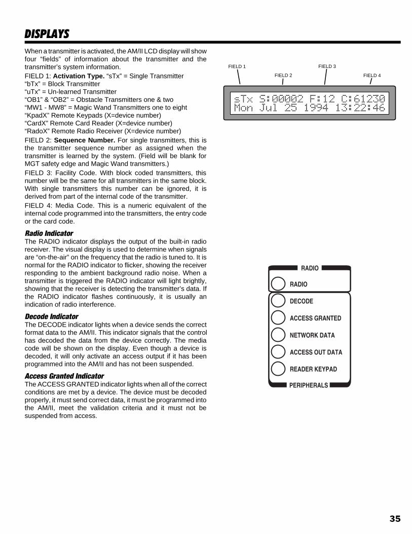
DISPLAYSWhen a transmitter is activated, the AM/II LCD display will showfour “fields” of information about the transmitter and thetransmitter’s system information.FIELD 1: Activation Type. “sTx” = Single Transmitter“bTx” = Block Transmitter“uTx” = Un-learned Transmitter“OB1” & “OB2” = Obstacle Transmitters one & two“MW1 - MW8” = Magic Wand Transmitters one to eight“KpadX” Remote Keypads (X=device number)“CardX” Remote Card Reader (X=device number)“RadoX” Remote Radio Receiver (X=device number)FIELD 2: Sequence Number. For single transmitters, this isthe transmitter sequence number as assigned when thetransmitter is learned by the system. (Field will be blank forMGT safety edge and Magic Wand transmitters.)FIELD 3: Facility Code. With block coded transmitters, thisnumber will be the same for all transmitters in the same block.With single transmitters this number can be ignored, it isderived from part of the internal code of the transmitter.FIELD 4: Media Code. This is a numeric equivalent of theinternal code programmed into the transmitters, the entry codeor the card code.
Radio IndicatorThe RADIO indicator displays the output of the built-in radioreceiver. The visual display is used to determine when signalsare “on-the-air” on the frequency that the radio is tuned to. It isnormal for the RADIO indicator to flicker, showing the receiverresponding to the ambient background radio noise. When atransmitter is triggered the RADIO indicator will light brightly,showing that the receiver is detecting the transmitter’s data. Ifthe RADIO indicator flashes continuously, it is usually anindication of radio interference.
Decode IndicatorThe DECODE indicator lights when a device sends the correctformat data to the AM/II. This indicator signals that the controlhas decoded the data from the device correctly. The mediacode will be shown on the display. Even though a device isdecoded, it will only activate an access output if it has beenprogrammed into the AM/II and has not been suspended.
Access Granted IndicatorThe ACCESS GRANTED indicator lights when all of the correctconditions are met by a device. The device must be decodedproperly, it must send correct data, it must be programmed intothe AM/II, meet the validation criteria and it must not besuspended from access.
FIELD 1
FIELD 2
FIELD 3
FIELD 4
35

KEYPAD FUNCTIONS
Data Entry KeysThe arrow keys (⇑ ⇓ ⇐ ⇒) are used to navigate through thevarious menu trees during programming.The up and down arrows change the display to the previous ornext programming item. Items that are above or below eachother in the programming menu trees can be selected usingthe up and down arrow keys.The OK key is used to accept an entry or to branch to sub-menuitems in the programming menu trees. Items that blink in thedisplayed menus are the current selection, (⇐ & ⇒) scrolls toa new selection. Pressing OK accepts that item and enters itinto the system’s memory.
Numeric KeypadThe numeric keypad is used to enter area numbers, mediacodes and any other numeric data required duringprogramming. Special key combinations are used for specialfunctions (resetting supervisory low battery, status and troubleindications from MGT safety edge transmitters).
[*] KeyThe [*] key has several functions. Pressing and holding the [*]key for about three seconds will cause the AM/II to ask for apassword to enter Program Mode. This is the only way to enterProgram Mode.While in Program Mode, the [*] key acts as an escape (cancel)key. Pressing the [*] key during any programming step willcancel any ongoing entries and return the display to the top ofthat area’s menu. Pressing the [*] key again will return thedisplay to the top of Area 01 (the first programming step).Pressing and holding the [*] key for about three seconds inProgram Mode will cause the AM/II to exit Program Mode andreturn to the normal Run Mode.While in Run Mode, pressing and holding the [*] key andpressing an ACCESS button will lock that relay closed,preventing any transmitters from activating that output. Theoutput can be unlocked by pressing the appropriate ACCESSbutton twice (to lock open, then to return to normal unlockedoperation).
[#] KeyThe [#] key is used as a shift key to activate special systemfunctions.Pressing and holding the [#] key and pressing [1] will reset anytrouble indications caused by supervised MGT safety edgetransmitters. If an MGT transmitter sends a trouble signal forlow battery, tamper or doesn’t send status signals for six hours,the OBSTACLE indicator will flash and a trouble message willbe shown on the LCD display. To clear the trouble indication,hold the [#] key and press [1].
Alphanumeric Data EntryThe AM/II keypad has alphanumeric capabilites. Each buttonon the numeric keypad can create five characters.The first press of the key enters the key number, presses 2-4enters a lower case alphabetic character. Press the [#] key tochange a lower case to an upper case letter. Press a numberkey then the [#] key for symbol characters.☞ NOTE: Entering alphanumeric characters is much easier
using a computer or data terminal through the RS-232 port.
OK
DATA ENTRY KEYS NUMERIC KEYPAD
m n o
d e f
v w x
b - .
j k l
a b c
s t u
p q r
g h i
y z ;
P R E S S [ # ] T OM A K E C A P I T A L
b = B L A N K
1 = =2 = @3 = #4 = $5 = %6 = ?7 = &8 = *9 = (0 = )
N U M T H E N[ # ] K E Y
36

SYSTEM PROGRAMMINGFollowing are instructions for programming each Area of theAM/II memory. Only the Areas pertaining to the specificinstallation need to be programmed. Reference the followingpages with the programming outline to complete the systemprogramming.The AM/II must be in Program Mode to perform any systemprogramming. FOLLOW THE STEPS IN THEPROGRAMMING OUTLINE TO PROGRAM THE SYSTEM.Because many of the features of the AM/II are interrelated,certain areas must be programmed before other areas.
Entering Program ModeSTEP 1 Enter programming mode by pressing and holding
the [*] key for about five seconds. With computeraccess press the ESC key.
STEP 2 Enter 123456 (if the system is new), or the correctpassword and press [OK].
Exiting Program ModeExit Program Mode by pressing and holding the [*] key for threeseconds. With computer access, press CTRL-Z.☞ NOTE: The system will automatically exit Program Mode
after five minutes of programming inactivity.
U P & D O W NA R R O W S W I L LM O V E B E T W E E NM E N U T O P I C S
[ O K ] K E Y S E L E C T SS U B - M E N U S
L E F T & R I G H TA R R O W S W I L LM O V E B E T W E E NM E N U I T E M S
B L I N K I N G I T E MI S T H E O N EC U R R E N T L YS E L E C T E D
[ O K ] K E Y E N T E R SS E L E C T E D M E N UI T E M I N T OM E M O R Y
[ O K ] K E Y E N T E R SN U M E R I C D A T AI N T O M E M O R Y
OK
AREA 01SINGLE TRANSMITTERS
Learn Single Xmtr(s) Press OK when Ready
1.1
1.2
1.3
1.4
1.5
1.1B
1.1ASelect Validation Group.0 1 2 3 4 5 6 7 8 9 10 11 12 13 14 15
Learning Transmitters Transmitter ID: = 0001
Enter Single Xmtr Numb Enter Xmtr. ID: 000
Suspend Single Xmtr.Transmitter ID: = [0000]
Reactivate Single Xmtr.Transmitter ID: = [0000]
Delete One Single Xmtr.Transmitter ID: = [0000]
Status of Single Xmtr.Transmitter ID: = [0000]
1.7
1.5AItem/Code: Press OK When Ready
1.6Enter Expiration Date. Expires On: mm/dd/yyyy
Delete All Single Xmtr.Are You Sure? Yes No
1.8
37

PROGRAMMING MENU TREES
AREA 13TIME ZONES
13.1
13.2
13.3
13.4
13.5
13.6
Which Time Zone [1-15] Time Zone Number: 00
Valid Days SMTWTFSH0=No, 1=Yes: 11111111
Period 1 Begin/End Time Tz[01]: 00:00/00:00
Period 2 Begin/End Time Tz[01]: 00:00/00:00
Period 3 Begin/End Time Tz[01]: 00:00/00:00
Period 4 Begin/End Time Tz[01]: 00:00/00:00
AREA 04MAGIC WAND TRANSMITTERS
Which MagicWand Xmtr.
Learning MagicWand Xmtr. Learned ID = 00000
4.1
4.2
4.3 4.3A
M W 1 M W 2 M W 3 M W 4 M W 5 M W 6 M W 7 M W 8
Transmitter Name.
Learn MagicWand Xmtr. Press OK when Ready.
Delete MagicWand Xmtr. Press OK when Ready.
4.4
AREA 11BUTTON SCHEDULES
11.1
11.2
11.3
11.4
Channel A Valid Buttons.N o n e A n y L e f t R i g h t T o p T o p & L f t T o p & R g t B t m L f t B t m R g t
Channel B Valid Buttons.N o n e A n y L e f t R i g h t T o p T o p & L f t T o p & R g t B t m L f t B t m R g t
Channel C Valid Buttons.N o n e A n y L e f t R i g h t T o p T o p & L f t T o p & R g t B t m L f t B t m R g t
Channel D Valid Buttons.N o n e A n y L e f t R i g h t T o p T o p & L f t T o p & R g t B t m L f t B t m R g t
AREA 12DOOR SCHEDULES
12.1
12.2
Which Door Sch. [1-15].Door Schedule Number: 0
Select Valid Doors ABCDDS[1]: 0=No, 1=Yes: 1111
AREA 07TELEPHONE ENTRY NUMBERS
7.1
7.2
7.3
7.4
7.5
Enter Directory Code Directory Code: 0000
Enter Telephone NumberTelephone#: ************
Enter Tenent Name
Extended Talk TimeYes No
Delete Directory Entry Directory Code: 0000
AREA 01SINGLE TRANSMITTERS
Learn Single Xmtr(s) Press OK when Ready
1.1
1.2
1.3
1.4
1.5
1.1B
1.1ASelect Validation Group.0 1 2 3 4 5 6 7 8 9 10 11 12 13 14 15
Learning Transmitters Transmitter ID: = 0001
Enter Single Xmtr Numb Enter Xmtr. ID: 000
Suspend Single Xmtr.Transmitter ID: = [0000]
Reactivate Single Xmtr.Transmitter ID: = [0000]
Delete One Single Xmtr.Transmitter ID: = [0000]
Status of Single Xmtr.Transmitter ID: = [0000]
1.7
1.5AItem/Code: Press OK When Ready
1.6Enter Expiration Date. Expires On: mm/dd/yyyy
AREA 03OBSTACLE TRANSMITTERS
Learning Obstacle Xmtr. Learned ID = 00000
3.1
3.2
3.3 3.3A
Which Obstacle Xmtr.OBTx1 OBTx2
Transmitter Name.
Learn Obstacle Xmtr. Press OK when Ready
Delete Obstacle Xmtr. Press OK when Ready
3.4
AREA 02BLOCK TRANSMITTERS
2.1
2.2
2.3
2.4
2.1A
2.1B
Enter Block Xmtr(s). Press OK when Ready
Enter Validation Group.0 1 2 3 4 5 6 7 8 9 10 11 12 13 14 15
Enter Block Range Start:End 00000:00000
Enter Transmitter Numb Enter ID Number: 00000
Suspend Block Xmtr.ID Number : [00000]
Reactivate Block Xmtr.ID Number : [00000]
2.5
2.6
Status of Block Xmtr.ID Number : [00000]
Delete All Block Xmtrs.Are You Sure? Yes No
2.5AItem/Code: Press OK When Ready
AREA 10VALIDATION GROUPS
10.1
Validation Group [1-15].Validation Group Num: 00
10.2Door Schedule [0-15]Door Schedule Number
10.3Choose First Time ZoneTime Zone [0-15] 00
10.4Choose Second Time ZoneTime Zone [0-15] 00
10.5Choose Third Time ZoneTime Zone [0-15] 00
10.6Choose Fourth Time ZoneTime Zone [0-15] 00
10.7Select Anti-Passback.None Timed
AREA 06BLOCK CARD CODES
6.1
6.2
6.36.4
6.1A
6.1B
Enter Validation Group.0 1 2 3 4 5 6 7 8 9 10 11 12 13 14 15
Enter Block Range Start:End 00000:00000
6.6
Enter Block Cards Press OK when Ready
Enter Card Number Enter ID Number: 00000
Suspend Block Card.ID Number : [00000]
Reactivate Block Card.ID Number : [00000]
Status of Block Card.ID Number : [00000]
Delete All Block Cards.Are You Sure? Yes No
6.5AItem/Code: Press OK When Ready
6.3
6.5
AREA 05ENTRY CODES
5.1
5.2
5.3
5.4
Select Validation Group.0 1 2 3 4 5 6 7 8 9 10 11 12 13 14 15
Enter Entry Code. Entry Code: ********
Suspend Entry Code. Entry Code: ********
Reactivate Entry Code. Entry Code: ********
Status of Entry Code. Entry Code: ********
Delete Single Entry Code Entry Code: ********
Delete All Entry Codes.Are You Sure? Yes No
5.5
5.6
5.7
38

CONFIGURE ACCESS OUTAREA 26
26.1
26.2
26.3
26.4
Access Out ModeValidation Pass-TXID Pass-SEQID
Access Out Facility Code Facility Code: 00000
Access Out Button OffsetOff On
Access Out FormatOff Wiegand26 Sentex30 SecuraKey31
FACILITY/SITE CODESAREA 23
23.1
23.2
23.3
System Site Code Site Code: 00000
Txmtr Facility Code Fac Code: 000
Card Facility Code 1 Fac Code [1]: 000
Card Facility Code 2 Fac Code [2]: 000
Card Facility Code 3 Fac Code [3]: 000
Card Facility Code 4 Fac Code [4]: 000
23.4
23.5
23.6
AREA 30SYSTEM REPORTS/UTILITIES
30.1
30.2
30.3
30.4
30.5
30.6
30.7
30.8
Print System ReportYes No
Print Single Xmtr ReportYes No
Print Block Xmtr ReportYes No
Print Entry Code ReportYes No
Print Block Card ReportYes No
Print Tele/Entry ReportYes No
EvntLog Rpt Start Date 00/00/1990
Print Event Log ReportAll SinceLastRpt FromDate
MEMORY MODULE UTILITIESAREA 29
29.1
29.2
29.3
29.4
29.5
Send Memory ModuleYes No
Receive Memory ModuleYes No
Copy Memory ModuleOff SendMM ReceiveMM
Print Memory ModuleYes No
Initialize Memory ModuleAre You Sure? Yes No
RS-232 PORT SETUPAREA 24
24.1
24.2
24.3
24.4
RS-232 Port DeviceOff Printer Modem Terminal PC
Modem Init. String 2ATH0&FS0=0E0&N6&H0Y1&W1
Modem Termination StringATH0
Modem Init. String 1ATH0&F0F8E0&K0&Q0&D0&W0
RELAY SETUPAREA 21
21.1
21.2
21.3
21.4
21.5
21.6
Which Relay to Program.CH-A CH-B CH-C CH-D
Select Operation:Control Shunt Alarm Obstacle CCTV
Select Timing Mode:Time Pulse Toggle Latch
Enter Activation Time: Time in seconds: 00000
21.7
21.8
Assign Time Zone [1]:0 1 2 3 4 5 6 7 8 9 10 11 12 13 14 15
21.9
21.10
21.11
Enter Channel Name
Assign Telephone DigitNone 1 2 3 4 5 6 7 8 9
Channel ControlNormal Activate LockOpen LockClosed
Assign Time Zone [2]:0 1 2 3 4 5 6 7 8 9 10 11 12 13 14 15
Assign Time Zone [3]:0 1 2 3 4 5 6 7 8 9 10 11 12 13 14 15
Assign Time Zone [4]:0 1 2 3 4 5 6 7 8 9 10 11 12 13 14 15
SYSTEM SETUPAREA 22
22.1
22.2
Installation Name
AM/II Name
22.3
22.4
22.5
22.6
22.7
22.8
22.9
22.10
Retained Event LogNone 500 1000 2000 5000 Max
Antipassback TimeNone 1min 2min 3min 4min
Integral Radio DirectionNone In Out Neutral
Network Address0ff 1 2 3 4 5 6 7 8
Keypad Strikes and Out Strikes Allowed: 0
Door Ajar Time Open Time Seconds: 000
Local Program Password Password: 123456
Remote Program Password Password: 123456
Priority Access Password Password: 123456
22.11
CONFIGURE REMOTE DEVICESAREA 25
25.1
25.2
25.3
25.4
25.5
25.6
Which Remote DeviceDV1 DV2 DV3 DV4 DV5 DV6 DV7
Assign Control ChannelCH-A CH-B CH-C CH-D Buttons
Access DirectionNone In Out Neutral
Enable Options ABCD0=No, 1=Yes: 1111
Enter Name for Device
Type of DeviceNone Keypad CardRdr Radio Relay Phone SecuraKey31
TIME AND CALENDARAREA 20
20.1
20.2
20.3
Enter Date as mm/dd/yyyy 05/26/1995
Select Daylight SavingsYes No
20.4Downlight On/Off time.On/Off: 00:00/00:00
20.5
20.6
Which Holiday [1-24] Holiday Number: 00
Holiday Number[]: DateHol[01] Month/Day 00/00
STANDARD time hh:mm 13:33
20.7
Which Ex Holiday [1-24]Holiday Number 00
20.8
Expiring Holiday XXMM/DD/YYYY 00/00/0000
TELEPHONE ENTRY SETUPAREA 27
27.1
27.2
27.3
27.4
27.6
Directory Code Length1 2 3 4
Directory Begins AtBeginning(A) Middle(M)
PBX Dialing DigitOff 9 8 7 6 5 4 3 2 1 0
27.7
27.8
27.9
27.10
Sort Directory Names NowYes No
Edit Display Messages Message Number: 00
Set Talk Time Talk Time Seconds: 060
Edit Display Message
Max Directory EntriesMaximum Entries: 00000
Delete All Tlph. EntriesYes No
27.5
27.11
Assign Postal Key DoorCH-A CH-B CH-C CH-D Buttons
Adjust Hybrid LevelPress OK To Start/Stop
27.12Display BrightnessDim Low Med High
27.13Priority Access ABCD0=No 1=Yes 0000
39

PROGRAMMING OUTLINEThe following outline is intended to guide you through theprogramming of an AM/II system. The AM/II is programmed bysetting options in various program “Areas”. Use this outline inconjunction with the following program area detail pages to setup the system.
1. Install and connect the AM/II as previously described.
2. Fill out the Programming Worksheet (P/N 211677).
3. Enter program mode (Hold the * key for 5 seconds or pressEsc on programming computer).
4. Set date and time (standard time) in Time and CalendarArea 20.
5. If the system is going to be networked, Area 22 NetworkAddress must be set. (If AccessBase is used, this is the onlylocal programing step needed.)
6. Determine the button configurations and enter them in ButtonSchedule Area 11.
7. Program any time zones in Time Zone Area 13.
8. Program the door access in Door Schedules Area 12.
9. Program the validation groups in Validation Group Area 10.
10. Set all additional system options in the System Setup Area 22.
11. Program all single transmitters using Single TransmittersArea 01.
12. Program all block coded transmitters using Block Area 02.
13. Program all MGT safety edge obstacle transmitters usingObstacle Transmitter Area 03.
14. Program all “MagicWand” transmitters using Magic Wand XmtrArea 04.
15. Program all keypad entry codes using Entry Code Area 05.
16. Program all block card codes using Block Card Codes Area 06.
17. Program the relay output options using Relay Setup Area 21.
18. Program the facility and site codes (if used) using Facility/SiteCodes Area 23.
19. Set any remote accessory device address and options usingConfigure Remote Devices Area 25.
20. If using the Model AE-1 or AE-2 telephone entry module,program the telephone entry settings using Telephone EntrySetup Area 27.
21. If using the Model AE-1 or AE-2 telephone entry module,program the telephone and directory numbers and namesusing Telephone Entry Numbers Area 07.
22. Setup the ACCESS OUT terminals if connecting to an externalaccess control panel using the Configure Access Out Area 26.
23. Examine the system, single transmitter, block transmitter, entrycode and block card reports for a system programmingoverview. Use the System Reports/Utilities Area 30 to view(using a terminal, computer or printer) the reports.
24. Test the system and adjust the red RADIO RANGE knob todetermine the optimum range of the receiver.
SETUP DATE AND TIME(AREA 20)
SET NETWORK ADDRESS(AREA 22)
SET BUTTON SCHEDULE(AREA 11)
SET TIME ZONES(AREA 13)
SET DOOR SCHEDULES(AREA 12)
SET VALIDATION GROUPS(AREA 10)
SET ALL SYSTEM OPTIONS(AREA 22)
PROGRAM SINGLETRANSMITTERS
(AREA 01)
PROGRAM BLOCK CODEDTRANSMITTERS
(AREA 02)
PROGRAM OBSTACLETRANSMITTERS
(AREA 03)
PROGRAM MAGIC WANDTRANSMITTERS
(AREA 04)
PROGRAM KEYPADENTRY CODES
(AREA 05)
PROGRAM BLOCKCARD CODES
(AREA 06)
SET RELAY OPTIONS(AREA 21)
SET FACILITY AND SITE CODES(AREA 23)
CONFIGURE REMOTE DEVICES(AREA 25)
CONFIGURE ACCESS OUT(AREA 26)
PRINT OR VIEWSYSTEM REPORTS
(AREA 30)
TEST SYSTEM
SETUP TELEPHONE ENTRY(AREA 27)
PROGRAM TELEPHONE ENTRYNUMBERS AND NAMES
(AREA 07)
40

AREA 01SINGLE TRANSMITTER PROGRAMMING
Area 01 is used to enter, suspend, reactivate, delete, andcheck the status of single transmitters. A validation groupcan be selected for each transmitter when it’s entered into
memory.
Each of the following activities are performed in programmingArea 01. From the main menu, use [⇑], [⇓] or enter “01” on thekeypad to scroll to “Single Transmitter(s), Enter ProgramArea 01” and press [OK]. Press [*] when finished to return tothe main menu.
Learning Single Transmitters➊ Use [⇑] or [⇓] to scroll to “Learn Single Xmtr(s)” and press [OK].➋ Use [⇐] or [⇒] to choose a validation group for the transmitter. Press
[OK] when desired selection is blinking.➌ Enter the desired transmitter ID# and activate the transmitter.
☞ NOTE: If the transmitter ID # is already in use, an asterisk will show beforethe ID #.
For additional transmitters in the same validation group, use [⇑] or [⇓] toselect the next ID# and repeat Step 3.For additional transmitters in different validation groups, press [OK] andrepeat Steps 1-3.
Suspending Single Transmitters➊ Use [⇑] or [⇓] to scroll to “Enter Single Xmtr Numb”.➋ Enter the transmitter ID# to suspend and press [OK].➌ Use [⇑] or [⇓] to select “Suspend Single Xmtr” and press [OK].
To suspend additional transmitters, repeat Steps 1-3.
Reactivating Single Transmitters➊ Use [⇑] or [⇓] to scroll to “Enter Single Xmtr Numb”.➋ Enter the transmitter ID# to reactivate and press [OK].➌ Use [⇑] or [⇓] to select “Reactivate Single Xmtr.” and press [OK].
To reactivate additional transmitters, repeat Steps 1-3.
Status of Single Transmitters➊ Use [⇑] or [⇓] to scroll to “Enter Single Xmtr Numb”.➋ Enter the transmitter ID# for status and press [OK].➌ Use [⇑] or [⇓] to select “Status of Single Xmtr.” and press [OK].
To view status of additional transmitters, press [OK] then repeat Steps 1-3.
Deleting One Single Transmitter➊ Use [⇑] or [⇓] to scroll to “Enter Single Xmtr Numb”.➋ Enter the transmitter ID# to delete and press [OK].➌ Use [⇑] or [⇓] to select “Delete Single Xmtr.” and press [OK].
To delete additional transmitters, repeat Steps 1-3.
Deleting All Single Transmitters➊ Use [⇑] or [⇓] to scroll to “Delete All Single Xmtr.”➋ Use the [⇐] and [⇒] keys to select “YES”.➌ Press [OK] to delete all single transmitter’s from the system.
AREA 01SINGLE TRANSMITTERS
Learn Single Xmtr(s) Press OK when Ready
1.1
1.2
1.3
1.4
1.5
1.1B
1.1ASelect Validation Group.0 1 2 3 4 5 6 7 8 9 10 11 12 13 14 15
Learning Transmitters Transmitter ID: = 0001
Enter Single Xmtr Numb Enter Xmtr. ID: 000
Suspend Single Xmtr.Transmitter ID: = [0000]
Reactivate Single Xmtr.Transmitter ID: = [0000]
Delete One Single Xmtr.Transmitter ID: = [0000]
Status of Single Xmtr.Transmitter ID: = [0000]
1.7
1.5AItem/Code: Press OK When Ready
1.6Enter Expiration Date. Expires On: mm/dd/yyyy
Delete All Single Xmtr.Are You Sure? Yes No
1.8
41

AREA 02BLOCK TRANSMITTERS
Area 02 is used to enter, suspend, reactivate, delete, andcheck the status of block coded transmitters. A validation
group can be selected for each transmitter block when it isentered into memory.
Each of the following activities are performed in programmingArea 02. From the main menu, use [⇑], [⇓] or enter “02” on thekeypad to scroll to “Block Transmitter(s), Enter ProgramArea 02” and press [OK]. Press [*] when finished to return tothe main menu.
Entering Block Transmitters➊ Use [⇑] or [⇓] to scroll to “Enter Block Xmtr(s)”.➋ Use [⇐] or [⇒] to choose a validation group for the transmitter block.
Press [OK] when desired selection is blinking.➌ Enter the numbers for the start and the end of the transmitter block and
press [OK].To learn additional block transmitters, repeat Steps 1-3.
Suspending Block Transmitters➊ Use [⇑] or [⇓] to scroll to “Enter Transmitter Numb”.➋ Enter the transmitter ID# to suspend and press [OK].➌ Use [⇑] or [⇓] to select “Suspend Block Xmtr” and press [OK].
To suspend any additional transmitters, repeat Steps 1-3.
Reactivating Block Transmitters➊ Use [⇑] or [⇓] to scroll to “Enter Transmitter Numb”.➋ Enter the transmitter ID# to reactivate and press [OK].➌ Use [⇑] or [⇓] to select “Reactivate Block Xmtr.” and press [OK].
To reactivate additional transmitters, repeat Steps 1 & 2.
Status of Block Transmitters➊ Use [⇑] or [⇓] to scroll to “Enter Transmitter Numb”.➋ Enter the transmitter ID# for status and press [OK].➌ Use [⇑] or [⇓] to select “Status of Block Xmtr.” and press [OK].
To view status of additional transmitters, press [OK] then repeat Steps 1-3.
Deleting All Block Transmitters➊ Use [⇑] or [⇓] to scroll to “Delete All Block Xmtrs”➋ Use the [⇐] and [⇒] keys to select “YES”.➌ Press [OK] to delete all block transmitter’s from the system.
AREA 02BLOCK TRANSMITTERS
2.1
2.2
2.3
2.4
2.1A
2.1B
Enter Block Xmtr(s). Press OK when Ready
Enter Validation Group.0 1 2 3 4 5 6 7 8 9 10 11 12 13 14 15
Enter Block Range Start:End 00000:00000
Enter Transmitter Numb Enter ID Number: 00000
Suspend Block Xmtr.ID Number : [00000]
Reactivate Block Xmtr.ID Number : [00000]
2.5
2.6
Status of Block Xmtr.ID Number : [00000]
Delete All Block Xmtrs.Are You Sure? Yes No
2.5AItem/Code: Press OK When Ready
42

AREA 03OBSTACLE TRANSMITTERS
Area 03 is used to enter, delete and define names forModel MGT obstacle transmitters.
Each of the following activities are performed in programmingArea 03. From the main menu, use [⇑], [⇓] or enter “03” on thekeypad to scroll to “Obstacle Transmitter(s), Enter ProgramArea 03” and press [OK]. Press [*] when finished to return tothe main menu.
Naming Obstacle Transmitters➊ Use [⇑] or [⇓] to scroll to “Which Obstacle Xmtr”.➋ Use [⇐] or [⇒] to select “OBTx1” or “OBTx2” (obstacle transmitter 1
for Channel C, obstacle transmitter 2 for Channel D). Press [OK] whendesired selection is blinking.
➌ Enter the transmitter name and press [OK].To name the other obstacle transmitter, repeat Steps 1-3.
Learning Obstacle Transmitters➊ Use [⇑] or [⇓] to scroll to “Which Obstacle Xmtr”.➋ Use [⇐] or [⇒] to select “OBTx1” or “OBTx2” (obstacle transmitter 1
for Channel C, obstacle transmitter 2 for Channel D). Press [OK] whendesired selection is blinking.
➌ Use [⇑] or [⇓] to scroll to “Learn Obstacle Xmtr.” and press [OK].➍ Activate MGT obstacle transmitter, display will show the learned ID#.
To learn the other obstacle transmitter, repeat Steps 1-4.
Deleting Obstacle Transmitters➊ Use [⇑] or [⇓] to scroll to “Which Obstacle Xmtr”.➋ Use [⇐] or [⇒] to select “OBTx1” or “OBTx2” (obstacle transmitter 1
for Channel C, obstacle transmitter 2 for Channel D). Press [OK] whendesired selection is blinking.
➌ Use [⇑] or [⇓] to scroll to “Delete Obstacle Xmtr.” and press [OK].To delete the other obstacle transmitter, repeat Steps 1-3.
AREA 03OBSTACLE TRANSMITTERS
Learning Obstacle Xmtr. Learned ID = 00000
3.1
3.2
3.3 3.3A
Which Obstacle Xmtr.OBTx1 OBTx2
Transmitter Name.
Learn Obstacle Xmtr. Press OK when Ready
Delete Obstacle Xmtr. Press OK when Ready
3.4
43
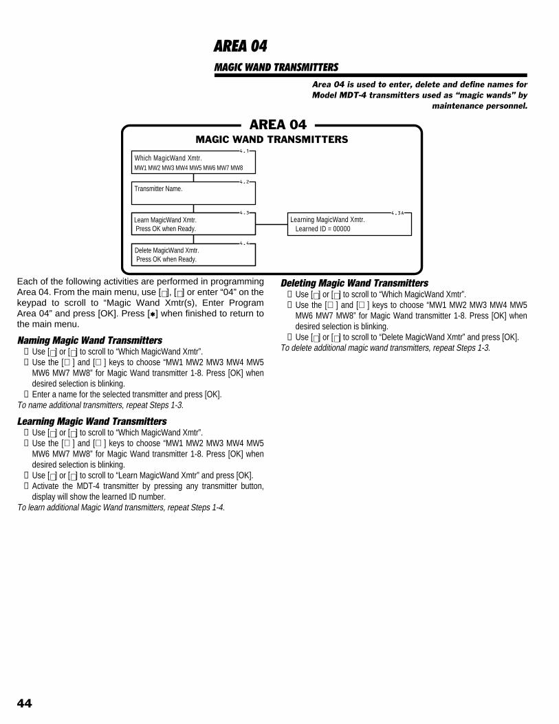
AREA 04MAGIC WAND TRANSMITTERS
Area 04 is used to enter, delete and define names forModel MDT-4 transmitters used as “magic wands” by
maintenance personnel.
Each of the following activities are performed in programmingArea 04. From the main menu, use [⇑], [⇓] or enter “04” on thekeypad to scroll to “Magic Wand Xmtr(s), Enter ProgramArea 04” and press [OK]. Press [*] when finished to return tothe main menu.
Naming Magic Wand Transmitters➊ Use [⇑] or [⇓] to scroll to “Which MagicWand Xmtr”.➋ Use the [⇐] and [⇒] keys to choose “MW1 MW2 MW3 MW4 MW5
MW6 MW7 MW8” for Magic Wand transmitter 1-8. Press [OK] whendesired selection is blinking.
➌ Enter a name for the selected transmitter and press [OK].To name additional transmitters, repeat Steps 1-3.
Learning Magic Wand Transmitters➊ Use [⇑] or [⇓] to scroll to “Which MagicWand Xmtr”.➋ Use the [⇐] and [⇒] keys to choose “MW1 MW2 MW3 MW4 MW5
MW6 MW7 MW8” for Magic Wand transmitter 1-8. Press [OK] whendesired selection is blinking.
➌ Use [⇑] or [⇓] to scroll to “Learn MagicWand Xmtr” and press [OK].➍ Activate the MDT-4 transmitter by pressing any transmitter button,
display will show the learned ID number.To learn additional Magic Wand transmitters, repeat Steps 1-4.
Deleting Magic Wand Transmitters➊ Use [⇑] or [⇓] to scroll to “Which MagicWand Xmtr”.➋ Use the [⇐] and [⇒] keys to choose “MW1 MW2 MW3 MW4 MW5
MW6 MW7 MW8” for Magic Wand transmitter 1-8. Press [OK] whendesired selection is blinking.
➌ Use [⇑] or [⇓] to scroll to “Delete MagicWand Xmtr” and press [OK].To delete additional magic wand transmitters, repeat Steps 1-3.
AREA 04MAGIC WAND TRANSMITTERS
Which MagicWand Xmtr.
Learning MagicWand Xmtr. Learned ID = 00000
4.1
4.2
4.3 4.3A
MW1 MW2 MW3 MW4 MW5 MW6 MW7 MW8
Transmitter Name.
Learn MagicWand Xmtr. Press OK when Ready.
Delete MagicWand Xmtr. Press OK when Ready.
4.4
44

AREA 05ENTRY CODES
Area 05 is used to enter, suspend, reactivate, delete, andcheck the status of keypad entry codes. A validation groupcan be selected for each entry code when it is entered into
memory.
Each of the following activities are performed in programmingArea 05. From the main menu, use [⇑], [⇓] or enter “05” on thekeypad to scroll to “Entry Codes, Enter Program Area 05” andpress [OK]. Press [*] when finished to return to the main menu.
Entering Entry Codes☞ NOTE: Entry codes should all have the same length. For the
best security, the entry codes should be at least four digitslong.
➊ Use [⇑] or [⇓] to scroll to “Select Validation Group”.➋ Use [⇐] or [⇒] to choose a validation group for the entry code. Press
[OK] when desired selection is blinking.➌ Enter up to eight digits for the entry code and press [OK].
For additional entry codes with the same validation group repeat Step 3. Forentry codes in other validation groups, repeat Steps 1-3.
Suspending Entry Codes➊ Use [⇑] or [⇓] to scroll to “Suspend Entry Code”.➋ Enter the entry code to suspend and press [OK].
To suspend additional entry codes, repeat Steps 1 & 2.
Reactivating Entry Codes➊ Use [⇑] or [⇓] to scroll to “Reactivate Entry Code”.➋ Enter the entry code to reactivate and press [OK].
To reactivate additional entry codes, repeat Steps 1 & 2.
Status of Entry Codes➊ Use [⇑] or [⇓] to scroll to “Status of Entry Code”.➋ Enter the entry code for status and press [OK].
To view status of additional entry codes, press [OK] then repeat Steps 1 & 2.
Deleting One Single Entry Code➊ Use [⇑] or [⇓] to scroll to “Delete Single Entry Code”.➋ Enter the entry code to delete and press [OK].
To delete additional entry codes, repeat Steps 1 & 2.
Deleting All Entry Codes➊ Use [⇑] or [⇓] to scroll to “Delete All Entry Codes”.➋ Use [⇐] or [⇒] to select “YES”.➌ Press [OK] to delete all entry codes from the system.
AREA 05ENTRY CODES
5.1
5.2
5.3
5.4
Select Validation Group.0 1 2 3 4 5 6 7 8 9 10 11 12 13 14 15
Enter Entry Code. Entry Code: ********
Suspend Entry Code. Entry Code: ********
Reactivate Entry Code. Entry Code: ********
Status of Entry Code. Entry Code: ********
Delete Single Entry Code Entry Code: ********
Delete All Entry Codes.Are You Sure? Yes No
5.5
5.6
5.7
45

AREA 06BLOCK CARD CODES
Area 06 is used to enter, suspend, reactivate, delete, andcheck the status of swipe cards entered as a block. A
validation group can be selected for each card block when itis entered into memory.
Each of the following activities are performed in programmingArea 06. From the main menu, use [⇑], [⇓] or enter “06” on thekeypad to scroll to “Block Card Codes, Enter Program Area 06”and press [OK]. Press [*] when finished to return to the mainmenu.
Entering Block Card Codes➊ Use [⇑] or [⇓] to scroll to “Enter Block Cards”.➋ Use [⇐] or [⇒] to choose a validation group for the transmitter block.
Press [OK] when desired selection is blinking.➌ Enter the numbers for the start and the end of the card block and press
[OK].To enter additional block card codes, repeat Steps 1-3.
Suspending Block Card Codes➊ Use [⇑] or [⇓] to scroll to “Enter Card Number”.➋ Enter the card number to suspend and press [OK].➌ Use [⇑] or [⇓] to select “Suspend Block Card” and press [OK].
To suspend any additional block cards, repeat Steps 1-3.
Reactivating Block Card Codes➊ Use [⇑] or [⇓] to scroll to “Enter Card Number”.➋ Enter the card number to reactivate and press [OK].➌ Use [⇑] or [⇓] to select “Reactivate Block Card” and press [OK].
To reactivate additional block cards, repeat Steps 1 & 2.
Status of Block Card Codes➊ Use [⇑] or [⇓] to scroll to “Enter Card Number”.➋ Enter the card number for status and press [OK].➌ Use [⇑] or [⇓] to select “Status of Block Card” and press [OK].
To view status of additional block cards, press [OK] then repeat Steps 1-3.
Deleting All Block Card Codes➊ Use [⇑] or [⇓] to scroll to “Delete All Block Cards”➋ Use the [⇐] and [⇒] keys to select “YES”.➌ Press [OK] to delete all block card codes from the system.
AREA 06BLOCK CARD CODES
6.1
6.2
6.36.4
6.1A
6.1B
Enter Validation Group.0 1 2 3 4 5 6 7 8 9 10 11 12 13 14 15
Enter Block Range Start:End 00000:00000
6.6
Enter Block Cards Press OK when Ready
Enter Card Number Enter ID Number: 00000
Suspend Block Card.ID Number : [00000]
Reactivate Block Card.ID Number : [00000]
Status of Block Card.ID Number : [00000]
Delete All Block Cards.Are You Sure? Yes No
6.5AItem/Code: Press OK When Ready
6.3
6.5
46

AREA 07TELEPHONE ENTRY NUMBERS
Area 07 is used to enter and delete telephone directorycodes, tenant names and select extended talk time for
users. (A Model AE-1 or AE-2 telephone entry module isrequired to use these functions.)
Each of the following activities are performed in programmingArea 07. From the main menu, use [⇑], [⇓] or enter “07” on thekeypad to scroll to “Telephone Entry Numbers, Enter ProgramArea 07” and press [OK]. Press [*] when finished to return tothe main menu.☞ NOTE: The AE-1 or AE-2 Telephone Entry Module must be
installed to use these functions.
Entering Tenant Names & Numbers➊ Use [⇑] or [⇓] to scroll to “Enter Directory Code”.➋ Enter the tenant’s directory code number and press [OK].➌ Enter the tenant’s name (up to 24 characters, but only the first 16 (AE-1)
and the first 20 (AE-2) can be displayed on the current models), andpress [OK].
➍ Enter the tenant’s telephone number and press [OK].➎ Use [⇐] or [⇒] to choose “YES” or “NO” for “Extended Talk Time”.
Press [OK] when the desired selection is blinking.To enter additional tenant information, repeat Steps 1-5.
Deleting Directory Entries➊ Use [⇑] or [⇓] to scroll to “Enter Directory Code”.➋ Enter the tenant’s directory code number to delete and press [OK].
To delete additional tenant entries, repeat Steps 1 & 2.
AREA 07TELEPHONE ENTRY NUMBERS
7.1
7.2
7.3
7.4
7.5
Enter Directory Code Directory Code: 0000
Enter Telephone NumberTelephone#: ************
Enter Tenent Name
Extended Talk TimeYes No
Delete Directory Entry Directory Code: 0000
47

AREA 10VALIDATION GROUPS
Area 10 is used to program door schedules, time zones andanti-passback selection for each of the 15 validation groups.
Each of the following activities are performed in programmingArea 10. From the main menu, use [⇑], [⇓] or enter “10” on thekeypad to scroll to “Validation Groups, Enter Program Area 10”and press [OK]. Press [*] when finished to return to the mainmenu.☞ NOTE: Door schedules, time zones and button schedule
should be set before programming the validation groups.When a validation group is programmed, it aquires thebutton schedule that is currently set.
Configuring Validation Groups➊ Use [⇑] or [⇓] to scroll to “Validation Group [1-15]”.➋ Enter the number of the validation group to program and press [OK].➌ Unit displays: “Door Schedule [0-15]”. Enter 0-7 to select a door
schedule for the validation group selected and press [OK]. (Doorschedule 0 allows access to all four relay channels.)
➍ Unit displays: “Which Time Zone [0-15]”. Enter 0-15 to select a timezone for the validation group selected and press [OK]. (Time zone 0allows access at any time.)
➎ Use [⇐] or [⇒] to choose “None” or “Timed” for “Select Anti-Passback”for the validation group selected. When the desired selection is blinking,press [OK].
To program additional validation groups, repeat Steps 1-5.
AREA 10VALIDATION GROUPS
10.1
Validation Group [1-15].Validation Group Num: 00
10.2Door Schedule [0-15]Door Schedule Number
10.3Choose First Time ZoneTime Zone [0-15] 00
10.4Choose Second Time ZoneTime Zone [0-15] 00
10.5Choose Third Time ZoneTime Zone [0-15] 00
10.6Choose Fourth Time ZoneTime Zone [0-15] 00
10.7Select Anti-Passback.None Timed
48

AREA 11BUTTON SCHEDULES
Area 11 is used to program which transmitter buttonsactivate which relay channel. When a validation group isprogrammed, it will acquire the current button schedule.
Each of the following activities are performed in programmingArea 11. From the main menu, use [⇑], [⇓] or enter “11” on thekeypad to scroll to “Button Schedule, Enter Program Area 11”and press [OK]. Press [*] when finished to return to the mainmenu.☞ NOTE: Set the button schedule before programming any
validation groups. When validation groups are programmed,they aquire the current button schedule.
Setting the Channel “A” Button Schedule➊ Use [⇑] or [⇓] to scroll to “Channel A Valid Buttons”➋ Use [⇐] or [⇒] to choose which transmitter button(s) will activate relay
channel “A”. Press [OK] when the desired selection is blinking.
Setting the Channel “B” Button Schedule➊ Use [⇑] or [⇓] to scroll to “Channel B Valid Buttons”➋ Use [⇐] or [⇒] to choose which transmitter button(s) will activate relay
channel “B”. Press [OK] when the desired selection is blinking.
Setting the Channel “C” Button Schedule➊ Use [⇑] or [⇓] to scroll to “Channel C Valid Buttons”➋ Use [⇐] or [⇒] to choose which transmitter button(s) will activate relay
channel “C”. Press [OK] when the desired selection is blinking.
Setting the Channel “D” Button Schedule➊ Use [⇑] or [⇓] to scroll to “Channel D Valid Buttons”➋ Use [⇐] or [⇒] to choose which transmitter button(s) will activate relay
channel “D”. Press [OK] when the desired selection is blinking.
AREA 11BUTTON SCHEDULES
11.1
11.2
11.3
11.4
Channel A Valid Buttons.None Any Left Right Top Top&Lft Top&Rgt BtmLft BtmRgt
Channel B Valid Buttons.None Any Left Right Top Top&Lft Top&Rgt BtmLft BtmRgt
Channel C Valid Buttons.None Any Left Right Top Top&Lft Top&Rgt BtmLft BtmRgt
Channel D Valid Buttons.None Any Left Right Top Top&Lft Top&Rgt BtmLft BtmRgt
49

AREA 12DOOR SCHEDULES
Area 12 is used to program which of the four relay channelscan be activated by each of the fifteen door schedules. Each
validation group can use one of the fifteen door schedules.
Each of the following activities are performed in programmingArea 12. From the main menu, use [⇑], [⇓] or enter “12” on thekeypad to scroll to “Door Schedule, Enter Program Area 12”and press [OK]. Press [*] when finished to return to the mainmenu.
Setting the Door Schedules➊ Use [⇑] or [⇓] to scroll to “Which Door Sch. [1-15]”. Enter 1-15 and press
[OK].➋ Each door schedule has selectors for relay channels A, B, C & D.
0 = NO (door schedule cannot activate relay channel)1 = YES (door schedule can activate relay channel)Use [⇐] or [⇒] to choose which selector to change and enter a “0” todisable or “1” to enable the relay access for that door schedule. Press[OK] when finished.
To set more door schedules, repeat Steps 1 & 2.
AREA 12DOOR SCHEDULES
12.1
12.2
Which Door Sch. [1-15].Door Schedule Number: 0
Select Valid Doors ABCDDS[1]: 0=No, 1=Yes: 1111
50

AREA 13TIME ZONES
Area 13 is used to program the 15 time zones. Days ofoperation, four time periods and a holiday enable can be
programmed for each time zone. Each validation group canuse one of the 15 time zones.
Each of the following activities are performed in programmingArea 13. From the main menu, use [⇑], [⇓] or enter “13” on thekeypad to scroll to “Time Zones, Enter Program Area 13” andpress [OK]. Press [*] when finished to return to the main menu.
Setting the Time Zones➊ Use [⇑] or [⇓] to scroll to “Which Time Zone [1-15]”.➋ Enter the number of the time zone to program and press [OK].➌ Unit displays: “Valid Days SMTWTFSH”
Each time zone has selectors for active days of the week and holidays.0 = NO (time zone cannot activate any relays on this day)1 = YES (time zone can activate relays on this day)Use [⇐] or [⇒] to choose which selector to change and enter a “0” todisable or “1” to enable the time zone for that day. Press [OK] whenfinished.
☞ NOTE: Holiday dates are set in Area 20 “Time and Calendar”.➍ Unit displays: “Period 1 Begin/End Time”. Enter the starting and ending
times (24 hour format: 1pm=13:00) for this time period. The time zoneselected will have access between the time periods entered. Press [OK].
➎ Unit displays: “Period 2 Begin/End Time”. Enter the starting and endingtimes (24 hour format: 1pm=13:00) for this time period. The time zoneselected will have access between the time periods entered. Press [OK].
➏ Unit displays: “Period 3 Begin/End Time”. Enter the starting and endingtimes (24 hour format: 1pm=13:00) for this time period. The time zoneselected will have access between the time periods entered. Press [OK].
➐ Unit displays: “Period 4 Begin/End Time”. Enter the starting and endingtimes (24 hour format: 1pm=13:00) for this time period. The time zoneselected will have access between the time periods entered. Press [OK].
☞ NOTE: Setting all four periods beginning and ending times to 00:00allows 24-hour access for that time zone (same as using time zone “0”in a validation group.
AREA 13TIME ZONES
13.1
13.2
13.3
13.4
13.5
13.6
Which Time Zone [1-15] Time Zone Number: 00
Valid Days SMTWTFSH0=No, 1=Yes: 11111111
Period 1 Begin/End Time Tz[01]: 00:00/00:00
Period 2 Begin/End Time Tz[01]: 00:00/00:00
Period 3 Begin/End Time Tz[01]: 00:00/00:00
Period 4 Begin/End Time Tz[01]: 00:00/00:00
51

AREA 20TIME AND CALENDAR
Area 20 is used to set the date and time, select daylightsavings adjustment, program keypad downlight times and
program the 24 possible holiday dates.
Each of the following activities are performed in programmingArea 20. From the main menu, use [⇑], [⇓] or enter “20” on thekeypad to scroll to “Time and Calendar, Enter ProgramArea 20” and press [OK]. Press [*] when finished to return tothe main menu.
Setting the Time➊ Use [⇑] or [⇓] to scroll to “STANDARD time hh:mm”➋ Enter the current standard time in HH:MM 24-hour format (1pm=13:00)
HH=hours (00-23)MM=minutes (00-59)Press [OK] after entering the time.
Setting the Date➊ Use [⇑] or [⇓] to scroll to “Enter Date as mm/dd/yyyy”➋ Enter the current date in the mm/dd/yyyy American format:
mm=month (01-12)dd=day (01-31)yyyy=year (1995-2089)Press [OK] after entering the date.
Daylight Savings Option➊ Use [⇑] or [⇓] to scroll to “Select Daylight Savings”.➋ Use [⇐] or [⇒] to select “Yes” or “No” for daylight savings time
adjustment. When the desired response is blinking, press [OK].
Setting Keypad Downlight Time➊ Use [⇑] or [⇓] to scroll to “Downlight On/Off time”.➋ Enter an on and off time for the downlight on Model AM-KP keypads.
Enter the time in HH:MM 24-hour format (1pm=13:00).
Setting Holiday Dates➊ Use [⇑] or [⇓] to scroll to “Which Holiday [1-24]”➋ Enter the holiday number and press [OK].➌ Enter the date of the holiday in mm/dd format:
mm=month (01-12)dd=day (01-31)Press [OK].
To add additional holidays, repeat Steps 1-3.
Setting Expiring Holiday Dates➊ Use [⇑] or [⇓] to scroll to Ex Holidays.➋ Enter date of holiday in mm/dd/yyyy
mm=month (01-12)dd=day (01-31)yyyy=(1999, etc.)
TIME AND CALENDARAREA 20
20.1
20.2
20.3
Enter Date as mm/dd/yyyy 05/26/1995
Select Daylight SavingsYes No
20.4Downlight On/Off time.On/Off: 00:00/00:00
20.5
20.6
Which Holiday [1-24] Holiday Number: 00
Holiday Number[]: DateHol[01] Month/Day 00/00
STANDARD time hh:mm 13:33
20.7
Which Ex Holiday [1-24]Holiday Number 00
20.8
Expiring Holiday [XX]MM/DD/YYYY 00/00/0000
52

AREA 21RELAY SETUP
Area 21 is used to program the four relay channels. Eachchannel can be given a name and programmed for type ofoperation. The contact action and timing, the selection of
which telephone digit and which time zone will causeactivation are also programmed.
Relay Timing OptionsEach relay can be programmed for timed, pulse, toggle orlatching modes of operation. With the timed option, the lengthof activation time can be set.
Timed OperationTimed operation makes the relay stay activated for the lengthof time that it is programmed.
Pulse OperationPulse operation causes the relay to activate for just 1/4 secondeach time it is triggered.
Toggle OperationToggle operation causes the relay to engage with the firstactivation and disengage with the next activation.
Latching OperationLatching operation causes the relay to stay engaged afteractivation until it is reset by pressing ACCESS button for therelay channel on the AM/II.☞ NOTE: If relay channels “C” & “D” are used for obstacle
outputs. If they are set to latch, they will only latch when atrouble signal is sent from an MGT safety edge transmitter.When the relays are set to latch, a normal obstacle signalwill cause the relays to operate in the timed mode.
Each of the following activities are performed in programmingArea 21. From the main menu, use [⇑], [⇓] or enter “21” on thekeypad to scroll to “Relay Setup, Enter Program Area 21” andpress [OK]. Press [*] when finished to return to the main menu.
Relay Programming➊ Use [⇑] or [⇓] to scroll to “Which Relay to Program”.➋ Use [⇐] or [⇒] to select “CH-A CH-B CH-C CH-D” relay to program.
Press [OK] when desired selection is blinking.➌ Unit displays: “Select Operation:”. Use [⇐] or [⇒] to select “Control
Shunt Alarm Obstacle CCTV” for the relay. Press [OK] when desiredselection is blinking.
☞ NOTE: Relays “A” & “B” can only be programmed as control relays. TheCCTV option can only be used if the Model AE-1 or AE-2 Telephone Entrymodule is installed.
➍ Unit displays: “Select Timing Mode:”. Use [⇐] or [⇒] to select “TimePulse Toggle Latch” for the relay. Press [OK] when desired selection isblinking.
➎ Unit displays: “Enter Activation Time:”. Enter the time in seconds for therelay to activate. Press [OK].
➏ Unit displays: “Assign Time Zone [1]:”. Use [⇐] or [⇒] to select a timezone to cause the relay to activate automatically during the time zone.(Time zone “0” allows normal activation). Continue for time zones 2,3,and 4. Press [OK] when desired selection is blinking.
➐ Unit displays: “Enter Channel Name”. Enter a name/location for the relaychannel for the event log. Press [OK].
➑ Unit displays: “Assign Telephone Digit”. Use [⇐] or [⇒] to select whichtelephone digit (1-9) will activate the relay.
☞ NOTE: This option can only be used if the Model AE-1 or AE-2 TelephoneEntry module is installed.
➒ Unit displays: “Channel Control”. Use [⇐] or [⇒] to activate, lock openor lock close the relay selected.
To program the other relays, repeat steps 1-8.
RELAY SETUPAREA 21
21.1
21.2
21.3
21.4
21.5
21.6
Which Relay to Program.CH-A CH-B CH-C CH-D
Select Operation:Control Shunt Alarm Obstacle CCTV
Select Timing Mode:Time Pulse Toggle Latch
Enter Activation Time: Time in seconds: 00000
21.7
21.8
Assign Time Zone [1]:0 1 2 3 4 5 6 7 8 9 10 11 12 13 14 15
21.9
21.10
21.11
Enter Channel Name
Assign Telephone DigitNone 1 2 3 4 5 6 7 8 9
Channel ControlNormal Activate LockOpen LockClosed
Assign Time Zone [2]:0 1 2 3 4 5 6 7 8 9 10 11 12 13 14 15
Assign Time Zone [3]:0 1 2 3 4 5 6 7 8 9 10 11 12 13 14 15
Assign Time Zone [4]:0 1 2 3 4 5 6 7 8 9 10 11 12 13 14 15
53

AREA 22SYSTEM SETUP
Area 22 is used to program a variety of system functions.These functions should be set before programming theother areas. Passwords, system names, event log and
anti-passback timing, and many other system settings areprogrammed in this area.
Each of the following activities are performed in programmingArea 22. From the main menu, use [⇑], [⇓] or enter “22” on thekeypad to scroll to “System Setup, Enter Program Area 22” andpress [OK]. Press [*] when finished to return to the main menu.
Setting Installation and Unit Names➊ Use [⇑] or [⇓] to scroll to “Installation Name”.➋ Enter the location name for the installation event log (up to 24
characters) and press [OK].➌ Use [⇑] or [⇓] to scroll to “AM/II Name”.➍ Enter the unit name for the installation event log (up to 24 characters)
and press [OK].
Setting Event Log Limits➊ Use [⇑] or [⇓] to scroll to “Retained Event Log”.➋ Use [⇐] or [⇒] to select “None 500 1000 2000 5000 Max”. Press [OK]
when desired selection is blinking.
Setting Anti-Passback Time➊ Use [⇑] or [⇓] to scroll to “Antipassback Time”.➋ Use [⇐] or [⇒] to select “None 1min 2min 3min 4min”. Press [OK] when
desired selection is blinking.
Setting Intregral Radio Direction➊ Use [⇑] or [⇓] to scroll to “Integral Radio Direction”.➋ Use [⇐] or [⇒] to select “None In Out Neutral”. Press [OK] when
desired selection is blinking. Select “IN”, it is the only functioning optionat this time.
Setting Network Address➊ Use [⇑] or [⇓] to scroll to “Network Address”.➋ Use [⇐] or [⇒] to select “OFF” or 1-8 for the network address. Press
[OK] when desired selection is blinking. After pressing [OK], press thereset button.
☞ NOTE: Resetting the unit assures network activation. After reset, thenetwork LED will be blinking.
Setting Keypad Strike Outs➊ Use [⇑] or [⇓] to scroll to “Keypad Strikes and Out”.➋ Enter the number of keypad attempts allowed (1-7) before keypad
lockout and press [OK].
Setting Door Ajar Time➊ Use [⇑] or [⇓] to scroll to “Door Ajar Time”.➋ Enter the time in seconds that all doors are allowed to be open after
access without causing an alarm. Press [OK].
Setting Local Password☞ NOTE: The local password must be six digits long. Include any leading
zeros when entering the code.➊ Use [⇑] or [⇓] to scroll to “Local Program Password”.➋ Enter the new six-digit password and press [OK].
Setting Remote Password☞ NOTE: The remote password must be six digits long. Include
any leading zeros when entering the code.➊ Use [⇑] or [⇓] to select “Remote Program Password”.➋ Enter the six-digit password and press [OK].
✘ CAUTION: Write the new passwords down and keepthem in a safe place. Programming access is impossiblewithout the proper password. If you forget thepassword, cal l Linear Technical Services forinstructions for resetting the passwords to the factorydefault.
Setting Priority Access Password☞ NOTE: The priority access password must be six digits long.
➊ Use [⇑] or [⇓] to select “Priority Access Password”.➋ Enter the six digit password and press [OK].
SYSTEM SETUPAREA 22
22.1
22.2
Installation Name
AM/II Name
22.3
22.4
22.5
22.6
22.7
22.8
22.9
22.10
Retained Event LogNone 500 1000 2000 5000 Max
Antipassback TimeNone 1min 2min 3min 4min
Integral Radio DirectionNone In Out Neutral
Network Address0ff 1 2 3 4 5 6 7 8
Keypad Strikes and Out Strikes Allowed: 0
Door Ajar Time Open Time Seconds: 000
Local Program Password Password: 123456
Remote Program Password Password: 123456
Priority Access Password Password: 123456
22.11
54

AREA 23Facility/Site Codes
Area 23 is used to program the system site code, thetransmitter facility code and the four card facility codes.
Facility and site codes are used in networked installationsand when the AM/II is connected to an external access
control system.
Each of the following activities are performed in programmingArea 23. From the main menu, use [⇑], [⇓] or enter “23” on thekeypad to scroll to “Facility/Site Codes, Enter ProgramArea 23” and press [OK]. Press [*] when finished to return tothe main menu.
System Site Code➊ Use [⇑] or [⇓] to scroll to “System Site Code”.➋ Enter the five-digit “System Site Code” and press [OK]. The custom
system site code number for entry cards is determined by Linear at thetime of the block coded transmitter order.
Transmitter Facility Code☞ NOTE: The Transmitter Facility Code is only used with block coded
transmitters.➊ Use [⇑] or [⇓] to scroll to “Txmtr Facility Code”.➋ Enter the three-digit transmitter facility code and press [OK]. The
transmitter facility code for the block of transmitters is labeled on thetransmitter master carton. The custom facility code number isdetermined by Linear at the time of the block coded transmitter order.
Card Facility Codes☞ NOTE: The Card Facility Codes are only used with block coded entry
cards. The card facility code for the block of entry cards is labeled on thecards’ master carton.
➊ Use [⇑] or [⇓] to scroll to “Card Facility Code 1”.➋ Enter the three-digit card facility code for code #1 and press [OK].➌ Use [⇑] or [⇓] to scroll to “Card Facility Code 2”.➍ Enter the three-digit card facility code for code #2 and press [OK].➎ Use [⇑] or [⇓] to scroll to “Card Facility Code 3”.➏ Enter the three-digit card facility code for code #3 and press [OK].➐ Use [⇑] or [⇓] to scroll to “Card Facility Code 4”.➑ Enter the three-digit card facility code for code #4 and press [OK].
FACILITY/SITE CODESAREA 23
23.1
23.2
23.3
System Site Code Site Code: 00000
Txmtr Facility Code Fac Code: 000
Card Facility Code 1 Fac Code [1]: 000
Card Facility Code 2 Fac Code [2]: 000
Card Facility Code 3 Fac Code [3]: 000
Card Facility Code 4 Fac Code [4]: 000
23.4
23.5
23.6
55

AREA 24RS-232 PORT SETUP
Area 24 is used to set the RS-232 port to function for aprinter, modem, terminal or PC. The modem initialization
and termination strings are also set in Area 24.
Each of the following activities are performed in programmingArea 24. From the main menu, use [⇑], [⇓] or enter “24” on thekeypad to scroll to “RS-232 Port Setup, Enter ProgramArea 24” and press [OK]. Press [*] when finished to return tothe main menu.
Setting RS-232 Device➊ Use [⇑] or [⇓] to scroll to “RS-232 Port Device”.➋ Use [⇐] or [⇒] to select “Off Printer Modem Terminal PC” for the
RS-232 device. Press [OK] when desired selection is blinking.Choose “Off” if nothing is connected to the port.Choose “Printer” if the port is connected to a printer.Choose “Modem” if the port is connected to a modem.Choose “Terminal” if the port is connected to a data terminal or a PCrunning a terminal program.Choose “PC” if the port is connected to a PC to receive raw standardtransaction string data for further processing.
Changing Modem Initialization Strings☞ Modem initialization string #1 is sent to the modem first, then string #2 is
sent. The termination string is sent to hangup the modem. The defaultmodem strings are set for the Linear’s Model AM-MOD modem. Thestrings my need to be changed if a different modem is used.
➊ Use [⇑] or [⇓] to scroll to “Modem Init. String 1”.➋ Edit the initialization string #1 as required by your modem. Press [OK].➌ Use [⇑] or [⇓] to scroll to “Modem Init. String 2”.➍ Edit the initialization string #2 as required by your modem. Press [OK].
Setting Modem Termination String➊ Use [⇑] or [⇓] to scroll to “Modem Termination String”.➋ Edit the termination string as required by your modem. Press [OK].
RS-232 PORT SETUPAREA 24
24.1
24.2
24.3
24.4
RS-232 Port DeviceOff Printer Modem Terminal PC
Modem Init. String 2ATH0&FS0=0E0&N6&H0Y1&W1
Modem Termination StringATH0
Modem Init. String 1ATH0&F0F8E0&K0&Q0&D0&W0
56

AREA 25CONFIGURE REMOTE DEVICES
Area 25 is used to set the seven remote device addresses tothe type of device connected to the AM/II. The remote
devices can be keypads, card readers, remote radioreceivers, control relays, and telephone entry modules. A
relay channel can be assigned to each device and fouroptions can be selected for each device.
Each of the following activities are performed in programmingArea 25. From the main menu, use [⇑], [⇓] or enter “25” on thekeypad to scroll to “Configure Remote Devices, Enter ProgramArea 25” and press [OK]. Press [*] when finished to return tothe main menu.
Remote Device Programming➊ Use [⇑] or [⇓] to scroll to “Which Remote Device”.➋ Use [⇐] or [⇒] to select [DV1] to [DV7]. Press [OK] when desired
device selection is blinking.☞ NOTE: Device [DV7] is reserved for the Model AE-1 or AE-2 telephone
entry module.➌ Unit displays: “Type of Device”. Use [⇐] or [⇒] to select “None Keypad
CardRdr Radio Relay Phone” for the selected device address. Press[OK] when desired selection is blinking.Use “Keypad” for Model AM-KP keypad.Use “CardRdr” for Model AM-CRI card reader interface.Use “Radio” for Models AM-RRR & AM-RPR radio receivers.Use “Relay” for Model AM-RLY relay interface.Use “Phone” for Model AE-1 or AE-2 telephone entry interface ([DV7]only).Use “SecuraKey31” for SecuraKey devices.
☞ NOTE: Relays “A” & “B” can only be programmed as control relays. TheCCTV option can only be used if the Model AE-1 or AE-2 Telephone Entrymodule is installed.
➍ Unit displays: “Assign Control Channel”. Use [⇐] or [⇒] to select relaychannel A-D that the device will activate. Press [OK] when desiredselection is blinking.
➎ Unit displays: “Access Direction”. Select “None In Out Neutral” to matchthe direction of access that the remote device permits. Press [OK] whendesired selection is blinking.
➏ Unit displays: “Enable Options ABCD”Each remote device has selectors for four function options (A-D).0 = NO (option disabled)1 = YES (option enabled)See the tables above. Use [⇐] or [⇒] to choose which selector tochange and enter a “0” or “1”. Press [OK] when finished.
➐ Unit displays: “Enter Name for Device”. Enter a name/location for theremote device. Press [OK].
To configure additional remote devices, repeat Steps 1-7.
CONFIGURE REMOTE DEVICESAREA 25
25.1
25.2
25.3
25.4
25.5
25.6
Which Remote DeviceDV1 DV2 DV3 DV4 DV5 DV6 DV7
Assign Control ChannelCH-A CH-B CH-C CH-D Buttons
Access DirectionNone In Out Neutral
Enable Options ABCD0=No, 1=Yes: 1111
Enter Name for Device
Type of DeviceNone Keypad CardRdr Radio Relay Phone SecuraKey31
AM-KP OPTIONS
OPTION “A” 0 = KEYPAD BEEPS OFF1 = KEYPAD BEEPS ON
OPTION “B”0 = KEYPAD DOWNLIGHT TIMING OFF1 = KEYPAD DOWNLIGHT TIMING ON
OPTION “C” 0 = KEYPAD DOWNLIGHT ALWAYS OFF1 = KEYPAD DOWNLIGHT ALWAYS ON
OPTION “D” 0 = KEYPAD BEEPS OFF1 = KEYPAD BEEPS ON
AM-CRI OPTIONS
OPTION “A” 0 = TBD1 = TBD
OPTION “B” 0 = TBD1 = TBD
OPTION “C”0 = TBD1 = TBD
OPTION “D” 0 = TBD1 = TBD
AM-RRR OPTIONS
OPTION “A” 0 = TBD1 = TBD
OPTION “B”0 = TBD1 = TBD
OPTION “C” 0 = TBD1 = TBD
OPTION “D” 0 = TBD1 = TBD
AM-RPR OPTIONS
OPTION “A” 0 = TBD1 = TBD
OPTION “B” 0 = TBD1 = TBD
OPTION “C”0 = TBD1 = TBD
OPTION “D” 0 = TBD1 = TBD
57

AREA 26CONFIGURE ACCESS OUT
Area 26 is used to setup the access out terminals whenconnecting the AM/II to an external access control system.The access out format, data mode, facility code and button
offset can be programmed in this area.
Each of the following activities are performed in programmingArea 26. From the main menu, use [⇑], [⇓] or enter “26” on thekeypad to scroll to “Access Out Format, Enter ProgramArea 26” and press [OK]. Press [*] when finished to return tothe main menu.
Access Out Application NoteThe format of the data that is sent to an external access controlpanel through the ACCESS OUT terminals is programmable inArea 26. Currently the AM/II can send Wiegand26,SecuraKey31 or Sentex30 format data.Three different data structures can be selected for each format.Each selects which data is sent out.VALIDATION: If this option is selected, data will only get sentfrom the ACCESS OUT terminals when media is grantedaccess by the AM/II. The data sent is the Access Out FacilityCode and the media ID number.PASS-TXID: If this option is selected, data will always get sentfrom the ACCESS OUT terminals when any media is decoded,regardless if access is granted by the AM/II. The data sent isthe Access Out Facility Code and the media ID number.PASS-SEQID: If this option is selected, data will always getsent from the ACCESS OUT terminals when any validtransmitter is decoded, regardless if access is granted by theAM/II. The data sent is the Access Out Facility Code and thetransmitter sequence number.
Access Out Setup☞ NOTE: Refer to the Advanced Programming Bulletin
(P/N 210516) for expanded details on programming theAM/II to activate other access control panels.
➊ Use [⇑] or [⇓] to select “Access Out Format”.➋ Use [⇐] or [⇒] to select “Off Wiegand26 Sentex30 SecuraKey31” for
the access out data format. Match the format with the type of accesscontrol panel connected to the ACCESS OUT terminals. Press [OK]when desired selection is blinking.
➌ Unit displays: “Access Out Mode”. Use the [⇐] and [⇒] keys to select“Validation Pass-TXID Pass-SEQID” for the Access Out Mode. Press[OK] when desired selection is blinking. See Advanced ProgrammingBulletin for details.
➍ Unit displays: “Access Out Facility Code”. Enter the three-digit facilitycode and press [OK]. This code must be the same code as programmedinto the access control panel connected to the ACCESS OUT terminals.
➎ Unit displays: “Access Out Button Offset”. Use the [⇐] and [⇒] keysto select “Off On” for the Access Out Button Offset. Select “ON” ifseparate buttons on the same transmitter are intended to control twodifferent devices. Press [OK] when desired selection is blinking.
CONFIGURE ACCESS OUTAREA 26
26.1
26.2
26.3
26.4
Access Out ModeValidation Pass-TXID Pass-SEQID
Access Out Facility Code Facility Code: 00000
Access Out Button OffsetOff On
Access Out FormatOff Wiegand26 Sentex30 SecuraKey31
58
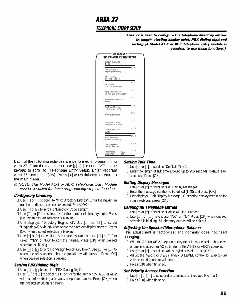
AREA 27TELEPHONE ENTRY SETUP
Area 27 is used to configure the telephone directory entriesby length, starting display point, PBX dialing digit and
sorting. (A Model AE-1 or AE-2 telephone entry module isrequired to use these functions.)
Each of the following activities are performed in programmingArea 27. From the main menu, use [⇑], [⇓] or enter “27” on thekeypad to scroll to “Telephone Entry Setup, Enter ProgramArea 27” and press [OK]. Press [*] when finished to return tothe main menu.☞ NOTE: The Model AE-1 or AE-2 Telephone Entry Module
must be installed for these programming steps to function.
Configuring Directory➊ Use [⇑] or [⇓] to scroll to “Max Directory Entries”. Enter the maximum
number of directory entries expected. Press [OK].➋ Use [⇑] or [⇓] to scroll to “Directory Code Length”.➌ Use [⇐] or [⇒] to select 1-4 for the number of directory digits. Press
[OK] when desired selection is blinking.➍ Unit displays: “Directory Begins At”. Use [⇐] or [⇒] to select
“Beginning(A) Middle(M)” for where the directory display starts at. Press[OK] when desired selection is blinking.
➎ Use [⇑] or [⇓] to scroll to “Sort Directory Names”. Use [⇐] or [⇒] toselect “YES” or “NO” to sort the names. Press [OK] when desiredselection is blinking.
➏ Use [⇑] or [⇓] to scroll to “Assign Postal Key Door”. Use [⇐] or [⇒] toselect the relay channel that the postal key will activate. Press [OK]when desired selection is blinking.
Setting PBX Dialing Digit➊ Use [⇑] or [⇓] to scroll to “PBX Dialing Digit”.➋ Use [⇐] or [⇒] to select “OFF” or 0-9 for the number the AE-1 or AE-2
will dial before dialing a tenant’s telephone number. Press [OK] whenthe desired selection is blinking.
Setting Talk Time➊ Use [⇑] or [⇓] to scroll to “Set Talk Time”.➋ Enter the length of talk time allowed up to 255 seconds (default is 60
seconds). Press [OK].
Editing Display Messages➊ Use [⇑] or [⇓] to scroll to “Edit Display Messages”.➋ Enter the message number to be edited (1-40) and press [OK].➌ Unit displays: “Edit Display Message”. Customize display message for
your needs and press [OK].
Deleting All Telephone Entries➊ Use [⇑] or [⇓] to scroll to “Delete All Tlph. Entries”.➋ Use [⇐] or [⇒] to choose “Yes” or “No”. Press [OK] when desired
selection is blinking. All directory entries will be deleted.
Adjusting the Speaker/Microphone BalanceThis adjustment is factory set and normally does not needchanging.
➊ With the AE-1or AE-2 telephone entry module connected to the activephone line, attach an AC voltmeter to the AE-1’s or AE-2’s speaker.
➋ Use [⇑] or [⇓] to scroll to “Adjust Hybrid Level”. Press [OK].➌ Adjust the AE-1’s or AE-2’s HYBRID LEVEL control for a minimum
voltage reading on the voltmeter.➍ Press [OK] when finished.
Set Priority Access Function➊ Use [⇐] or [⇒] to select relay to access and replace 0 with a 1.➋ Press [OK] when finished.
TELEPHONE ENTRY SETUPAREA 27
27.1
27.2
27.3
27.4
27.6
Directory Code Length1 2 3 4
Directory Begins AtBeginning(A) Middle(M)
PBX Dialing DigitOff 9 8 7 6 5 4 3 2 1 0
27.7
27.8
27.9
27.10
Sort Directory Names NowYes No
Edit Display Messages Message Number: 00
Set Talk Time Talk Time Seconds: 060
Edit Display Message
Max Directory EntriesMaximum Entries: 00000
Delete All Tlph. EntriesYes No
27.5
27.11
Assign Postal Key DoorCH-A CH-B CH-C CH-D Buttons
Adjust Hybrid LevelPress OK To Start/Stop
27.12Display BrightnessDim Low Med High
27.13Priority Access ABCD0=No 1=Yes 0000
59

AREA 29MEMORY MODULE UTILITIES
Area 29 is used for system service and maintenance. Thecontents of the AM/II’s memory module can be copied to a
PC or to another AM/II using this area. The memorycontents can also be printed or initialized (erased) using this
area.
Each of the following activities are performed in programmingArea 29. From the main menu, use [⇑], [⇓] or enter “29” on thekeypad to scroll to “Memory Module Utilities, Enter ProgramArea 29” and press [OK]. Press [*] when finished to return tothe main menu.
Sending Memory ModuleBefore sending the memory module contents, set the protocol to “XMODEM”in the receiving computer’s communication program. Connect the computerto the AM/II RS-232 port directly or use the Model AM-MOD modem forremote telephone connection.
➊ Use [⇑] or [⇓] to scroll to “Send Memory Module”.➋ Use [⇐] or [⇒] to select “Yes”. Press [OK].➌ Unit displays: “Begin File Transfer”. You have one minute to begin
receiving the memory file. Instruct the receiving computer’s software toreceive (download) the binary file.
➍ When the transfer is finished, the AM/II will display: “File TransferComplete”.
Receiving Memory ModuleBefore receiving the memory module contents, set the protocol to“XMODEM” in the sending computer’s communication program. Connect thecomputer to the AM/II RS-232 port directly or use the Model AM-MODmodem for remote telephone connection.
➊ Use [⇑] or [⇓] to scroll to “Receive Memory Module”.➋ Use [⇐] or [⇒] to select “Yes”. Press [OK].➌ Unit displays: “Begin File Transfer”. You have one minute to begin
sending the memory file. Instruct the sending computer’s software tosend (upload) the binary file.
➍ When the transfer is finished, the AM/II will display: “File TransferComplete”.
Copying Memory ModuleBefore copying the memory module contents to another AM/II, connect thetwo units together using the Model A2A cable. Set both unit’s RS-232 portdevice settings to “Off”.
➊ Use [⇑] or [⇓] to scroll to “Copy Memory Module” on both units.➋ Use [⇐] or [⇒] to select “ReceiveMM” on the receiving unit. Press [OK].➌ Use [⇐] or [⇒] to select “SendMM” on the sending unit. Press [OK].➍ When the transfer is finished, the AM/II will display: “File Transfer
Complete”. Press [OK] to continue.
Printing Memory Module➊ Use [⇑] or [⇓] to scroll to “Print Memory Module”.➋ Use [⇐] or [⇒] to select “Yes”. Press [OK]. The contents of the memory
module will be sent to the AM/II’s RS-232 port.
Initializing Memory Module✘ WARNING: Initializing the memory module will erase all
programmed data.➊ Use [⇑] or [⇓] to scroll to “Initialize Memory Module”.➋ Use [⇐] or [⇒] to select “Yes”. Press [OK]. The contents of the memory
module will be completely erased and the default values restored.
MEMORY MODULE UTILITIESAREA 29
29.1
29.2
29.3
29.4
29.5
Send Memory ModuleYes No
Receive Memory ModuleYes No
Copy Memory ModuleOff SendMM ReceiveMM
Print Memory ModuleYes No
Initialize Memory ModuleAre You Sure? Yes No
60

AREA 30SYSTEM REPORTS/UTILITIES
Area 30 is used to print the various system reports. Reportscan be sent to a printer on viewed on-line with a PC. System
configuration, single transmitter, block transmitter, entrycode, block card code, telephone entry and event log reports
are available.
Each of the following reports can be sent to a printer or viewedon a computer display or terminal. Connect the output deviceto the AM/II’s RS-232 port before selecting the report option.Each of the following activities are performed in programmingArea 30. From the main menu, use [⇑], [⇓] or enter “30” on thekeypad to scroll to “System Reports/Utilities, Enter ProgramArea 30” and press [OK]. Press [*] when finished to return tothe main menu.
Printing System Report➊ Use [⇑] or [⇓] to scroll to “Print System Report”.➋ Use [⇐] or [⇒] to select “Yes”. Press [OK].
Printing Single Transmitter Report➊ Use [⇑] or [⇓] to scroll to “Print Single Xmtr Report”.➋ Use [⇐] or [⇒] to select “Yes”. Press [OK].
Printing Block Transmitter Report➊ Use [⇑] or [⇓] to scroll to “Print Block Xmtr Report”.➋ Use [⇐] or [⇒] to select “Yes”. Press [OK].
Printing Entry Code Report➊ Use [⇑] or [⇓] to scroll to “Print Entry Code Report”.➋ Use [⇐] or [⇒] to select “Yes”. Press [OK].
Printing Block Card Report➊ Use [⇑] or [⇓] to scroll to “Print Block Card Report”.➋ Use [⇐] or [⇒] to select “Yes”. Press [OK].
Printing Telephone Entry Report➊ Use [⇑] or [⇓] to scroll to “Print Tele/Entry Report”.➋ Use [⇐] or [⇒] to select “Yes”. Press [OK].
Printing Event Log➊ Use [⇑] or [⇓] to scroll to “EvntLog Rpt Start Date”.➋ Enter the date for the start of the event log and press [OK].➌ Use [⇑] or [⇓] to scroll to “Print Event Log Report”.➍ Use [⇐] or [⇒] to select “All”, “SinceLastRpt” or “FromDate”. Press
[OK] when the desired selection is blinking.“All” = prints everything in the event log.“SinceLastRpt” = prints everything in the event log that occurred sincethe last time the event log was printed.“FromDate” = prints all events from the date entered in Step 2 to thepresent.
AREA 30SYSTEM REPORTS/UTILITIES
30.1
30.2
30.3
30.4
30.5
30.6
30.7
30.8
Print System ReportYes No
Print Single Xmtr ReportYes No
Print Block Xmtr ReportYes No
Print Entry Code ReportYes No
Print Block Card ReportYes No
Print Tele/Entry ReportYes No
EvntLog Rpt Start Date 00/00/1990
Print Event Log ReportAll SinceLastRpt FromDate
61

OPERATION OVERVIEWStandard OperationWhen a valid transmitter, entry code or card code is detected by thesystem, the control will activate the programmed relay output. If theAM/II is connected to a printer, a message is sent giving the codenumber, the time of activation, device and network number and relayactivated.The system’s clock has built-in battery backup to keep the timeaccurate during power loss. The time is displayed in 24-hour format.Suspending media codes allows the system administrator to deny auser’s access without removing their information from the system’smemory. Reactivating the media code allows the user to again haveaccess.Transmitters, cards and entry codes that are lost, stolen or need to beexchanged can be manually deleted from the system.
Manual OperationThe access outputs can be manually activated from the ACCESSbuttons on the AM/II. This is useful for maintenance personnel duringsetup and testing. Pressing any of the access buttons will latch itscorresponding relay output and light its LED indicator. Pressing thebutton again will unlatch the relay output and turn off the LED.
Magic Wand TransmittersUp to eight MDT-4 four-button transmitters can be programmed as“Magic Wand” transmitters. They allow maintenance personnel toremotely lock the relay outputs open or closed for Channels A & B.When service is being performed on a gate, maintenance personnelwill want to lock an output closed to prevent users from activating thedevice. With a Magic Wand transmitter, the device can be disabledremotely without having to disconnect the operator from the AM/II.When service is being performed on a door with a door strike,maintenance personnel might want to lock an output open toconstantly unlock the door during service.When programmed as a Magic Wand transmitter, the MDT-4 buttonsfunction as follows:
WHITE BUTTON: Locks Channel A open (relay activated).GREEN BUTTON: Locks Channel B open (relay activated).YELLOW BUTTON: Locks Channel A c losed (relayde-activated).RED BUTTON: Locks Channel B closed (relay de-activated).TOP BUTTON: Resets the AM/II.
Obstacle TransmittersOne or two MGT safety edge transmitters can be used with the AM/II.Obstacle transmitters #1 and #2 can be programmed to activate anyof the four relays.When a safety edge connected to an MGT transmitter is triggered, theappropriate output relay will activate, causing the operator to performan “obstacle cycle”.
The MGT safety edge transmitters are fully supervised. Everyhour they automatically send a status report to the AM/II. If theMGT has a low battery or the cover is tampered with, uniquesignals will be sent to the receiver. Trouble is indicated by aflashing OBSTACLE light on the AM/II. If the relay output is setto latch, it will latch only when there is trouble (it will be a timedoutput with a normal obstacle signal). The systems LCD displaywill state what the trouble is. If connected, the printer will logthe trouble. To clear the trouble indication, press # and 1.
*
5 6
7 8 9
0 #
1 2 3
4
RESETS THE AM/II
LOCKSCHANNEL "A"OPEN
LOCKSCHANNEL "B"OPEN
LOCKSCHANNEL "A"CLOSED
LOCKSCHANNEL "B"CLOSED
MAGIC WAND TRANSMITTER
MODEL MGT OBSTACLE TRANSMITTER
MANUALOPERATION
62

SPECIFICATIONSOutputs
RELAY Four form “C” relays (N.O. & N.C.)rated at 3 amps, 30 vol ts ,programmable output style andduration.
RS-232 One RS-232 port for connection to alocal line printer, PC for transactionlogging and modem for remoteprogramming.
LCD DISPLAY Integral 2 line by 24 character backlitdisplay for local programming andtransaction monitoring. Adjustabledisplay contrast.
LED INDICATORS Front panel indicators for all input andoutput activity for easy on-sitetroubleshooting.
InputsRF 318 MHz super-heterodyne receiver.
MegaCode format. Adjustable 20 dBattentuator for controlling radio range.
OPEN REQUEST Contact closure to ground activatescorresponding output relay.
DOOR SENSE Normally closed input to sense doorstatus.
KEYPAD Integral 17 key silicone rubber keypadfor local programming. Push buttonsfor manual control of relays.
HardwareAC INPUT POWER 14 to 24 VDC INPUT POWER 12 to 35 V
OPERATINGTEMPERATURE Electronics: -30 to +65° C
Display: 0 to +40° C (Frozen displaywill not affect system operation)
MEMORY All data memory is non-volatileEEPROM with data retention inexcess of ten years. Memory ishoused in a removable module foreasy transfer to another AM/II unit.
CLOCK/CALENDAR Bui l t - in bat tery backed-up
clock/calendar.
ConstructionCONNECTIONS Plug-on, screw terminal block.
DIMENSIONS 8.5" high, 9.75" wide, 2.25" deep.WEIGHT 3.5 Lbs.
63

INDEX
A AC & DC Power 23Access Buttons 5Access Devices 7Access Granted Indicator 35Access Media 15Access Out 18Access Out Connections 32Access Out Setup 58Access Out Terminals 5, 18Accessories 4Alarm Relay 29Alphanumeric Data Entry 36Antenna Input 5Antenna Installation 25Anti-passback 11Anti-passback Time 54
B Block Card Codes 46Block Card Report 61Block Coded Cards 34Block Coded Transmitters 34Block Diagram 6Block Transmitter Report 61Block Transmitters 42Button Schedule 8Button Schedules 49
C Cabinet Knockouts 22Cable Types Required 24Card Facility Codes 55Card Reader Interface 27CCTV Relay 29Configuring Validation Groups 48Contrast Control 5Control Inputs 27Control Relay 28Copying
Memory Module 60
D Data Entry Keys 5, 36Data Terminal Connections 31Daylight Savings Option 52Decode Indicator 35Deleting
All Block Card Codes 46All Block Transmitters 42All Entry Codes 45All Single Transmitters 41All Telephone Entries 59Directory Entries 47Magic Wand Transmitters 44Obstacle Transmitters 43One Single Entry Code 45Single Transmitters 41
Directory Configuration 59Display Messages 59Displays 35Door Ajar Time 54Door Schedules 9, 50Door Sense 27
E Earth Ground 23Earth Ground Terminal 5Editing
Display Messages 59Entering
Block Card Codes 46Block Transmitters 42Entry Codes 45Tenant Names & Numbers 47
Entering Program Mode 37Entry Code Report 61Entry Codes 45Event Log 13, 61Event Log Limits 54Exiting Program Mode 37External Access Control 7External Antenna 7External Control Indicators 5
F Facility Code 35Facility Codes 55Features 3, 5First Time Power-up 34
H Holiday Dates 52
IInitializing
Memory Module 60Installation Outline 20Installation Tips 21Internal Diagnostic Checks 34Intregral Radio Direction 54Introduction 2
KKeypad Downlight Time 52Keypad Entry Codes 34Keypad Functions 36Keypad In Terminals 5Keypad Strike Outs 54Keypad Strikeout 11
LLCD Display 5Learning
Magic Wand Transmitters 44Obstacle Transmitters 43Single Transmitters 41
Load Numbers 24Local Password 54
MMagic Wand Transmitters 44, 62Manual Operation 62Media Code 35Media Encoding 34Memory Expansion Card 5Memory Module Installation 21Memory Module Utilites 60Memory Utilities 19Modem Connections 31Modem Initialization Strings 56Modem Termination String 56Mounting Unit 22
N Naming
Magic Wand Transmitters 44Obstacle Transmitters 43
Network Address 54Network Connections 33Network Terminals 5, 18Networked Units 7Numeric Keypad 5, 36
64

O Obstacle Relay 29Obstacle Transmitters 43, 62Open Request 27Open Request and Door Sense Inputs 7Operating Temperature Range 22Operation Overview 62
P Pass-SEQID 58Pass-TXID 58PBX Dialing Digit 59Peripherals Indicators 5Personal Computer Connections 31Pound [#] Key 36Power Connections 23Power Light 5Power Switch 5Power Terminals 5Pre-installation 21Pre-installation Planning 20Printer Connection 30Printing
Block Card Report 61Block Transmitter Report 61Entry Code Report 61Event Log 61Memory Module 60Single Transmitter Report 61System Report 61Telephone Entry Report 61
Programming Menu Trees 38 - 39Programming Outline 40
R Radio Indicator 5, 35Radio Range Knob 5Radio Transmitters 7Reactivating
Block Card Codes 46Block Transmitters 42Entry Codes 45Single Transmitters 41
Reader In Terminals 5Receiving
Memory Module 60Relay Indicators 5Relay Options 28Relay Outputs 16, 28Relay Programming 53Relay Setup 53Relay Terminals 5Relay Timing Options 53Remote Device Programming 57Remote Devices 7, 14, 57Remote Keypad 26Remote Password 54
Remote Proximity Receiver 26Remote Radio Receiver 25Reset Button 5RS-232 Jack 5RS-232 Port 17, 30RS-232 Port Setup 56
SSending
Memory Module 60Sensing Inputs 16Sequence Number 35Serial Port 31Setting
Anti-passback Time 54Button Schedule 49Date 52Door Ajar Time 54Door Schedules 50Event Log Limits 54Holiday Dates 52Intregral Radio Direction 54Keypad Downlight Time 52Keypad Strike Outs 54Local Password 54Names 54Network Address 54Remote Password 54RS-232 Port Device 56Talk Time 59Time 52Time Zones 51
Shunt Relay 28Single Transmitter Programming 41Single Transmitter report 61Site Codes 55Specifications 63Standard Operation 62Star [*] Key 36Status
Block Card Codes 46Block Transmitters 42Entry Codes 45Single Transmitters 41
SuspendingBlock Card Codes 46Block Transmitters 42Entry Codes 45Single Transmitters 41
System Power-Up 34System Programming 37System Report 61System Reports 61System Setup 54System Site Code 55System Utilities 61
TTalk Time 59Telephone Entries 59Telephone Entry Numbers 47Telephone Entry Report 61Telephone Entry Setup 59Time and Calendar 52Time Zones 10, 51Transmitter Coding 34Transmitter Facility Code 55
U Unpacking the System 21
V Validation 58Validation Groups 12, 48
W Watchdog Monitor 34Wiring Requirements 24Wiring Strain Reliefs 5
65

LINEAR LIMITED WARRANTYThis Linear product is warranted against defects in material andworkmanship for twelve (12) months. The Warranty ExpirationDate is labeled on the product. This warranty extends onlyto wholesale customers who buy direct from Linear orthrough Linear’s normal distribution channels. Linear does notwarrant this product to consumers. Consumers shouldinquire from their selling dealer as to the nature of the dealer’swarranty, if any. There are no obligations or liabilities on thepart of Linear corporation for consequential damagesarising out of or in connection with use or performance ofthis product or other indirect damages with respect to lossof property, revenue, or profit, or cost of removal,installation, or reinstallation. All implied warranties, includingimplied warranties for merchantability and implied warrantiesfor fitness, are valid only until Warranty Expiration Date aslabeled on the product. This Linear Corporation Warranty isin lieu of all other warranties express or implied.All products returned for warranty service require a ReturnProduct Authorization Number (RPA#). Contact LinearTechnical Services at 1-800-421-1587 for an RPA# and otherimportant details.
IMPORTANT !!!Linear radio controls provide a reliable communications linkand fill an important need in portable wireless signalling.However, there are some limitations which must be observed.✶ For U.S. installations only: The radios are required to comply
with FCC Rules and Regulations as Part 15 devices. Assuch, they have limited transmitter power and thereforelimited range.
✶ A receiver cannot respond to more than one transmittedsignal at a time and may be blocked by radio signals thatoccur on or near their operating frequencies, regardless ofcode settings.
✶ Changes or modifications to the device may void FCCcompliance.
✶ Infrequently used radio links should be tested regularly toprotect against undetected interference or fault.
✶ A general knowledge of radio and its vagaries should begained prior to acting as a wholesale distributor or dealer,and these facts should be communicated to the ultimateusers.
Copyright © 1999 Linear Corporation 08-01-99 209369 B