wireless controlled residential air vent - faculty websites · wireless controlled residential air...
TRANSCRIPT
UNIVERSITY OF NEVADA LAS VEGAS
DEPARTMENT OF ELECTRICAL AND COMPUTER ENGINEERING
EE & CPE 497 Senior Design
Fall 2014
Wireless Controlled Residential Air Vent: A Smartphone Interface for Air Direction
Final Project Report
Group Members:
CPE
Name (Print) CPE/EE/ME
EE Name (Print) CPE/EE/ME

Introduction
Air conditioning (A/C) vents are stationary with permanently fixed fins. This means that
it can only direct airflow to the predetermined design of the vent. In some applications,
the airflow is scattered to areas that don’t need to be cooled or heated. For example,
couches or other pieces of furniture where people tend to spend most of their time in a
room can sometimes be placed in an area where the vents do not direct airflow to.
Another example can be found in bedrooms where the bed is placed in a position where
the airflow is directed straight to a resting person’s face which in some cases can cause
sinus problems. A need to manually control the A/C vents to direct airflow is the
solution to these issues.
Our project will have a full two dimensional control of the airflow coming out of a vent.
It will be an easy bolt-on replacement for the standard vents already installed in
residential homes and will be controlled via an application on a smart mobile device.
Once the app is installed, the user will be presented with a layout that will represent the
room and then the user will place the location of the vent. Once that is done, they will be
able to select the area of the room they want to direct the air towards or they can set the
vent to move in an oscillation mode. Depending on what they want, the vent can just
move side-to-side, up and down or both at the same time. Because we have such control
over the vent, we can also completely close the vent to a room with a simple button press
in the app in the event that room is no longer needed to be heated/cooled
System Specification
The proposed air vent will take on the dimensions of the already available vents that can
be found in residential homes. Figure 1 shows an image of traditional air vents that have
fixed fins and do not possess the capability to be controlled without the assistance of
manual labor if it is contains an opening and closing arm.
Figure 1: Fixed fin air vents
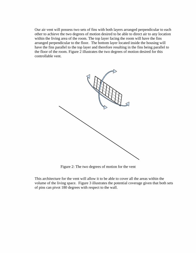
Our air vent will possess two sets of fins with both layers arranged perpendicular to each
other to achieve the two degrees of motion desired to be able to direct air to any location
within the living area of the room. The top layer facing the room will have the fins
arranged perpendicular to the floor. The bottom layer located inside the housing will
have the fins parallel to the top layer and therefore resulting in the fins being parallel to
the floor of the room. Figure 2 illustrates the two degrees of motion desired for this
controllable vent.
Figure 2: The two degrees of motion for the vent
This architecture for the vent will allow it to be able to cover all the areas within the
volume of the living space. Figure 3 illustrates the potential coverage given that both sets
of pins can pivot 180 degrees with respect to the wall.

Figure 3: Coverage of one vent in a cube shaped room
System Architecture
A. Architecture of the Vent The system will comprise of two servo motors that will move the fins on the vent.
One will be in charge of moving the x-axis and the other the y-axis. These servo
motors will be receiving commands from a microcontroller and the micro
controller will be receiving commands from RF transceivers. These RF
transceivers will be receiving data from a smart device such as smartphone or
tablet. Figure 4 shows the overview of the architecture of the design. The green
box in Figure 4 is intended to show the items installed on the PCB and will be
enclosed in a black box. This black box will be mounted on the back side of the
vent where it will be hidden from sight inside the duct work.

Figure 4: System Architecture
The components chosen to be integrated into our design will be discussed below:
I. Wi-Fi Module
The module of choice is Digi’s XBee Wi-Fi module. The part number is the
XB2B-WFWT-001. The specifications of this module can be observed in the
table below and has the PRO design.
Serial Data Interface UART up to 1Mbps, SPI up to 6 Mbps
Frequency Band ISM 2.4 GHz
ADC Inputs 4(12-bit)
Digital I/O 10
Operating Temperature -30˚C to +85˚C (-22˚F to 185˚F)
Network Security WPA-PSK,WPA2-PSK and WEP
Channels 13
WLAN Standard 802.11b/g/n
WLAN Data Rates 1Mbps to 72 Mbps
Transmit Power Up to +16dBm
Receiving Sensitivity -93 to -71 dBm
Supply Voltage 3.14 to 3.46 VDC
Transmit Current Up to 309mA
Receiver Current 100mA
Dimensions(L X W) 27.61mm X 24.38mm
iPhone
Interface
Wi-
Fi/ZigBee
Transceiver
Power
Supply
µ Controller
Wind
Flow
Sensor
Mechanical Connection
Power Wire
Control Wire
PCB located on vent

II. Microcontroller
The microcontroller used for this application is Atmel’s Atmega328P-PU. The
specifications can be observed in the table below.
Flash 32 KB
EEPROM 1 KB
RAM 2 KB
Pin Count 32
Max. Operating
Frequency
20MHz
CPU 8-bit AVR
I/O Pins 23
Operating Voltage 1.8V – 5.5V
Operating Temperature -40˚C to +85˚C (-40˚F to 185˚F)
ADC 8 (10-bit)
Power Consumption @ 1MHz, 1.8V, Active Mode: 0.2mA, Power-save mode: 0.75µA
Data Retention 20 years at 85˚C/ 100 years at 25˚C
III. Servo Motors
The servo motors used was the Power HD-1501MG sold by Pololu. This is an
analog servomotor that is controlled with pulse width modulation. The
specifications can be observed in the table below.
Limit angle 180˚plus or minus 10˚
Weight 63 plus or minus 1g
Operating Voltage 4.8V - 6.0V
Operating Temperature -10˚C – 50˚C (14˚F - 122˚F)
Dimensions 40.7x20.5x39.5mm
Stall Torque 17kg/cm
IV. Wind Sensor
The exact specifications for the wind sensor have not been sourced yet but it
will most likely be a thermal anemometer. This is a device that uses
something called a "hot-wire" technique. This technique involves heating an
element to a constant temperature and then measuring the electrical power that
is required to maintain the heated element at temperature as the wind changes.
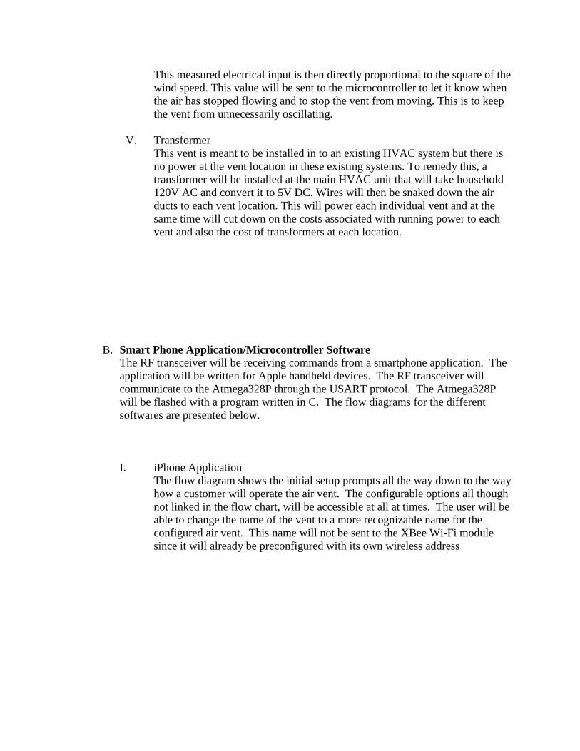
This measured electrical input is then directly proportional to the square of the
wind speed. This value will be sent to the microcontroller to let it know when
the air has stopped flowing and to stop the vent from moving. This is to keep
the vent from unnecessarily oscillating.
V. Transformer
This vent is meant to be installed in to an existing HVAC system but there is
no power at the vent location in these existing systems. To remedy this, a
transformer will be installed at the main HVAC unit that will take household
120V AC and convert it to 5V DC. Wires will then be snaked down the air
ducts to each vent location. This will power each individual vent and at the
same time will cut down on the costs associated with running power to each
vent and also the cost of transformers at each location.
B. Smart Phone Application/Microcontroller Software The RF transceiver will be receiving commands from a smartphone application. The
application will be written for Apple handheld devices. The RF transceiver will
communicate to the Atmega328P through the USART protocol. The Atmega328P
will be flashed with a program written in C. The flow diagrams for the different
softwares are presented below.
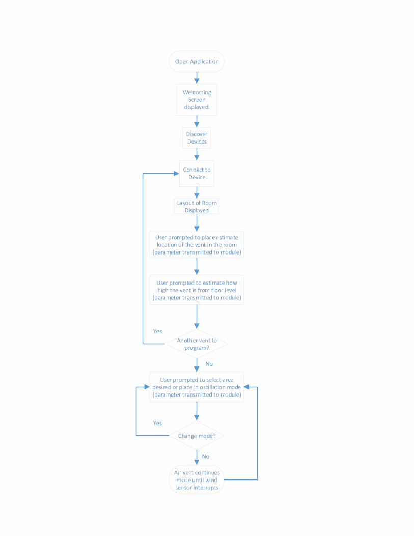
I. iPhone Application
The flow diagram shows the initial setup prompts all the way down to the way
how a customer will operate the air vent. The configurable options all though
not linked in the flow chart, will be accessible at all at times. The user will be
able to change the name of the vent to a more recognizable name for the
configured air vent. This name will not be sent to the XBee Wi-Fi module
since it will already be preconfigured with its own wireless address
Open Application
Welcoming Screen
displayed.
Yes
Yes
No
Discover Devices
Connect to Device
Layout of Room Displayed
User prompted to place estimate location of the vent in the room
(parameter transmitted to module)
User prompted to estimate how high the vent is from floor level
(parameter transmitted to module)
User prompted to select area desired or place in oscillation mode(parameter transmitted to module)
Another vent to program?
Change mode?
Air vent continues mode until wind sensor interrupts
No

OCR=2100
OCR=1200
OCR=400
OCR=1700
A
C
D
B
II. Atmega328P Software
The microcontroller will be written in C and will be in charge of moving two
servo motors. The flowchart below illustrates how it will be handling the
parameters being sent from the iPhone application. Figure 5 will serve as an
assist to follow the flow chart. Figure 5 shows the PWM values at each
degree of motion of the servo motor. For example, an OCR value of 2100
indicates the servo will point the fins at 180˚, OCR = 1200 points to 90˚, and
OCR = 0 points to 0˚. The regions labeled with letters will summarize the
desired location for the user. The prototype will assume vent is place in the
center of the wall selected.
Figure 5: Air vent and the parameters it uses to direct air flow to the desired
regions. This will serve for both servo motors, the one sweeping up and
down, and the other that sweeps side to side.

ParametersReceived
Vent onRight wall?
Adjust parameter for
height and initiate
movement of horizontal fins
Region A?
Region B?
Region C?
Region D?
Vent onFront wall?
Vent onBack wall?
Vent onLeft wall?
Vent onCeiling?
Region A?
Region B?
Region C?
Region D?
No
Yes
No
No
No
Yes
Yes
Yes
Yes
Initiate movement of vertical fins
Receive User parameter for desired airflow
No
No
No
No
OCR sweep from 1700 to 1200
OCR sweep from 1700 to 400
OCR sweep from 400 to 0
OCR sweep from 1700 to 2100
OCR sweep from 2100 to 0 on both servo
motors
OscillationMode?
Yes
No
OCR sweep from 1700 to 1200
OCR sweep from 1700 to 400
OCR sweep from 400 to 0
OCR sweep from 1700 to 2100
No
No
No
No
Yes
Yes
Yes
Yes
Yes
Yes
Yes
Yes
The above flow chart shows the flow of the code for a user selecting a single
point in a region specified in Figure 5. The program will have the capability
to select points that cross multiple regions but was not displayed in the flow
chart due to limited space.
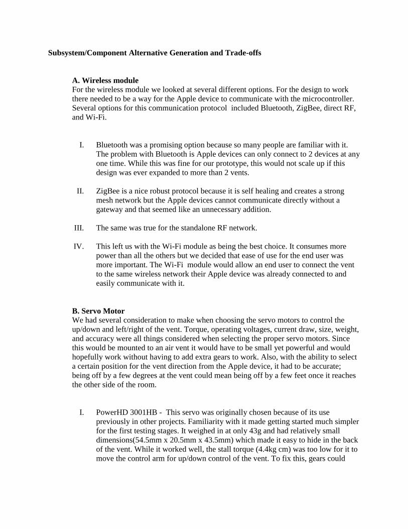
Subsystem/Component Alternative Generation and Trade-offs
A. Wireless module
For the wireless module we looked at several different options. For the design to work
there needed to be a way for the Apple device to communicate with the microcontroller.
Several options for this communication protocol included Bluetooth, ZigBee, direct RF,
and Wi-Fi.
I. Bluetooth was a promising option because so many people are familiar with it.
The problem with Bluetooth is Apple devices can only connect to 2 devices at any
one time. While this was fine for our prototype, this would not scale up if this
design was ever expanded to more than 2 vents.
II. ZigBee is a nice robust protocol because it is self healing and creates a strong
mesh network but the Apple devices cannot communicate directly without a
gateway and that seemed like an unnecessary addition.
III. The same was true for the standalone RF network.
IV. This left us with the Wi-Fi module as being the best choice. It consumes more
power than all the others but we decided that ease of use for the end user was
more important. The Wi-Fi module would allow an end user to connect the vent
to the same wireless network their Apple device was already connected to and
easily communicate with it.
B. Servo Motor
We had several consideration to make when choosing the servo motors to control the
up/down and left/right of the vent. Torque, operating voltages, current draw, size, weight,
and accuracy were all things considered when selecting the proper servo motors. Since
this would be mounted to an air vent it would have to be small yet powerful and would
hopefully work without having to add extra gears to work. Also, with the ability to select
a certain position for the vent direction from the Apple device, it had to be accurate;
being off by a few degrees at the vent could mean being off by a few feet once it reaches
the other side of the room.
I. PowerHD 3001HB - This servo was originally chosen because of its use
previously in other projects. Familiarity with it made getting started much simpler
for the first testing stages. It weighed in at only 43g and had relatively small
dimensions(54.5mm x 20.5mm x 43.5mm) which made it easy to hide in the back
of the vent. While it worked well, the stall torque (4.4kg cm) was too low for it to
move the control arm for up/down control of the vent. To fix this, gears could
have been added to change the torque of the output, but it would come at the cost
of speed and would also take up more room in the back of vent.
II. PowerHD 1501MG - Built on the same form factor as the 3001HB but having a
much higher stall torque (17kg cm), nearly the same speed, plus a nice price
point made it an good choice to use for control. Since the code written to control
the 3001HB worked and both were made by the same company with the same
connections, it made it a simple swap to get 4 times the torque.
C. Microcontroller
Finding the proper microcontroller is an important task as well. It was important to find a
balance between speed, features, and cost. In the search for microcontrollers we came up
with 3 candidates from ATMEL because they have a robust user community and a great
track record for supporting their products.
I. SAM3X8E - This microcontroller has a powerful 32-bit ARM processor that
would allow us to add any additional features in the future we could think of. It
would also give us extremely quick processing speed to minimize delay from
button press to system action. It turned out to be more processing power than we
really needed so we moved to a lower tier ATMEL product.
II. ATMEGA8 - This microcontroller has a 8-bit processor which we determined
would be fine for the design but it only had 8KB flash which might not be enough
if the design was ever expanded. Leaving room for expansion was one of the main
goals in this project.
III. ATMEGA328 - This microcontroller has the same 8-bit processor as the
ATMEGA8 but comes with 32KB flash which opens the possibility of future
expansion. Ultimately, this is the processor used for the design.
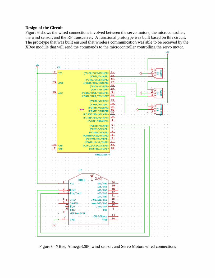
Design of the Circuit Figure 6 shows the wired connections involved between the servo motors, the microcontroller,
the wind sensor, and the RF transceiver. A functional prototype was built based on this circuit.
The prototype that was built ensured that wireless communication was able to be received by the
XBee module that will send the commands to the microcontroller controlling the servo motor.
Figure 6: XBee, Atmega328P, wind sensor, and Servo Motors wired connections
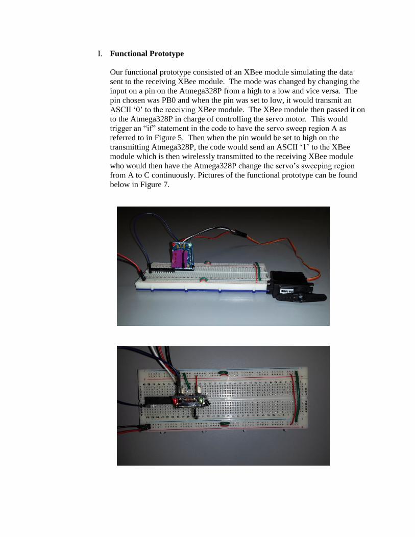
I. Functional Prototype
Our functional prototype consisted of an XBee module simulating the data
sent to the receiving XBee module. The mode was changed by changing the
input on a pin on the Atmega328P from a high to a low and vice versa. The
pin chosen was PB0 and when the pin was set to low, it would transmit an
ASCII ‘0’ to the receiving XBee module. The XBee module then passed it on
to the Atmega328P in charge of controlling the servo motor. This would
trigger an “if” statement in the code to have the servo sweep region A as
referred to in Figure 5. Then when the pin would be set to high on the
transmitting Atmega328P, the code would send an ASCII ‘1’ to the XBee
module which is then wirelessly transmitted to the receiving XBee module
who would then have the Atmega328P change the servo’s sweeping region
from A to C continuously. Pictures of the functional prototype can be found
below in Figure 7.

Figure 7: From top to bottom: 1. Side view of receiving circuit that controls the
servo motor. 2. Top view of receiving circuit that controls the servo motor. 3. Side
view of the circuit that transmits the user data. 4. Top view of the circuit that
transmits the user data.
This circuit performed ideally and it facilitates what kind of data will be
transmitted to the microcontroller. Almost negligible delay occurred when
transitioning from mode of operation. It was almost instant and the
continuous sweep occurred without any errors. If no mode is selected, then
the servo will not move. When the air sensor is obtained, it will connect to the

ATmega328P to cause an interrupt on PB7. This ensures the servo motors
will stop spinning if the AC has stopped outputting air.
Test Plan
A. Present Design
As stated earlier, the present design consists of two ATMEGA 328 microcontrollers
connected to two XBee wireless modules. One microcontroller sends a command to the
first XBee which then sends wirelessly to the second XBee which in turn relays that
command to the second microcontroller. That microcontroller then sends a signal to the
servo to tell it what position to rotate to. This design was built to show a proof of concept
that we could these parts to accomplish wireless control of the servo motors. The first
microcontroller and XBee module act as a simulation for the future Apple device that will
ultimately be controlling everything. Once we have shown that these parts will work, we
can then move on to the final project design that includes both servos and the Apple
device. This is the test plan for the current design.
I. Program microcontroller to oscillate between sending two different pulse widths
to move servo between 90 and 180 degrees to ensure proper control of servo.
II. Program microcontroller to change between 90 degree pulse and 180 degree pulse
by changing an input pin PB0 (14) from 5V to 0V.
III. Setup and connect both XBee modules to each other by first connecting them to
PC through COM ports.
IV. Test connection by sending serial string from one to the other and watching
transaction on PC.
V. Program "sending" microcontroller to send ASCII "1" or "0" depending on input
pin voltage. Connect the TX pin (3) of the microcontroller to the RX pin (3) on
the "sending" XBee.
VI. Connect to the "receiving" XBee with the PC and see if by changing the input pin
on the "sending" microcontroller it changes the serial string received by the
"receiving" XBee.
VII. Connect TX pin (2) of the "receiving" XBee to the RX pin (2) of the "receiving""
microcontroller and monitor output of the PB1 pin (15) on the "receiving"
microcontroller to make sure the pulse width changes while changing the input
pin voltage of the "sending" microcontroller.
VIII. Connect the PB1 pin of the "receiving" microcontroller to the signal input of the
servo motor and observe the changes to the position of the arm of the servo with
changes to the input pin voltages of the "sending" microcontroller.
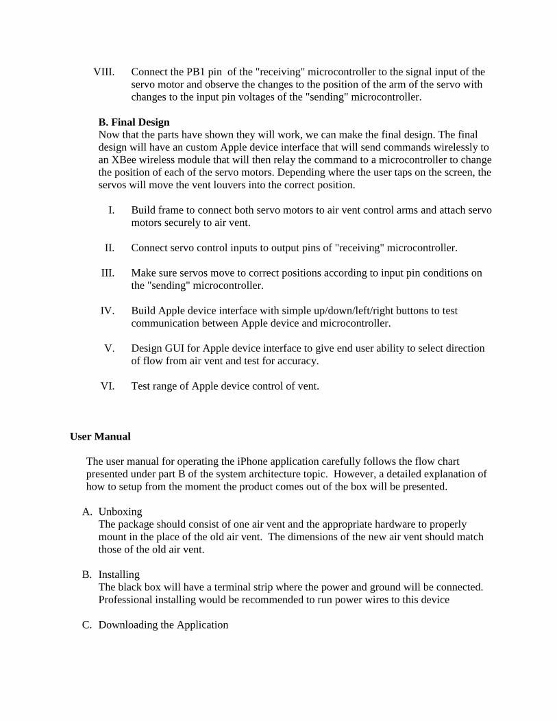
B. Final Design
Now that the parts have shown they will work, we can make the final design. The final
design will have an custom Apple device interface that will send commands wirelessly to
an XBee wireless module that will then relay the command to a microcontroller to change
the position of each of the servo motors. Depending where the user taps on the screen, the
servos will move the vent louvers into the correct position.
I. Build frame to connect both servo motors to air vent control arms and attach servo
motors securely to air vent.
II. Connect servo control inputs to output pins of "receiving" microcontroller.
III. Make sure servos move to correct positions according to input pin conditions on
the "sending" microcontroller.
IV. Build Apple device interface with simple up/down/left/right buttons to test
communication between Apple device and microcontroller.
V. Design GUI for Apple device interface to give end user ability to select direction
of flow from air vent and test for accuracy.
VI. Test range of Apple device control of vent.
User Manual
The user manual for operating the iPhone application carefully follows the flow chart
presented under part B of the system architecture topic. However, a detailed explanation of
how to setup from the moment the product comes out of the box will be presented.
A. Unboxing
The package should consist of one air vent and the appropriate hardware to properly
mount in the place of the old air vent. The dimensions of the new air vent should match
those of the old air vent.
B. Installing
The black box will have a terminal strip where the power and ground will be connected.
Professional installing would be recommended to run power wires to this device
C. Downloading the Application

The application will be available in the Apple Store. Once the vent has been setup, and
the application has been downloaded. You are ready to proceed to the step of
configuration.
D. Configuration
Step 1: Open the application and ensure the vent is powered on.
Step 2: Press the discover devices icon and wait for the application to display the device
that is installed. Once the device has been found, click the name of the RF transceiver.
Step 3: Now that you have established a connection to the RF transceiver in the air vent.
You will be displayed a layout of a room. Here you will be presented with an icon that
looks like an air vent and you will drag and drop it in place of where your air vent is
installed.
Step 4: Now you will be prompted to roughly estimate how high the air vent is placed off
the ground. This is to ensure that the horizontal fins compensate for where the room
floor is located.
Step 5: The air vent has been configured and you will be prompted to program another air
vent if more than one will be installed. If another vent is available, go back to step 2 so
that the smartphone may discover another device, otherwise, proceed to part E.
E. User Control
Now whenever you start the application, you will be presented with your connected
devices and you may change the name if so desired (i.e. Living room, kitchen, etc.).
Click on the device you want to operate and you will be presented with a square room
and the location of the vent. Now you will be able to control the air vent by pressing the
CONTROL icon. By doing so, you will be presented with the option to select from three
modes. Once the mode desired is selected, you will be presented with the representation
of the room again so that you may select your desired locations, below you will find how
each feature will work.
1. Single point direction.
Touch a location in the representation of the room and have the air vent direct
air flow to the desired location.
2. Multi point direction
Touch up to 4 locations in the representation of the room so that the air vent
can sweep air flow through these locations.
3. Oscillation
Here it will fix the x-axis of the vent to aim at the floor, and the y-axis of the
vent will sweep from left to right and then from right to left.
F. Extra Icons
You’ll be able to access the settings at all times where modifications to the parameters
can be performed.
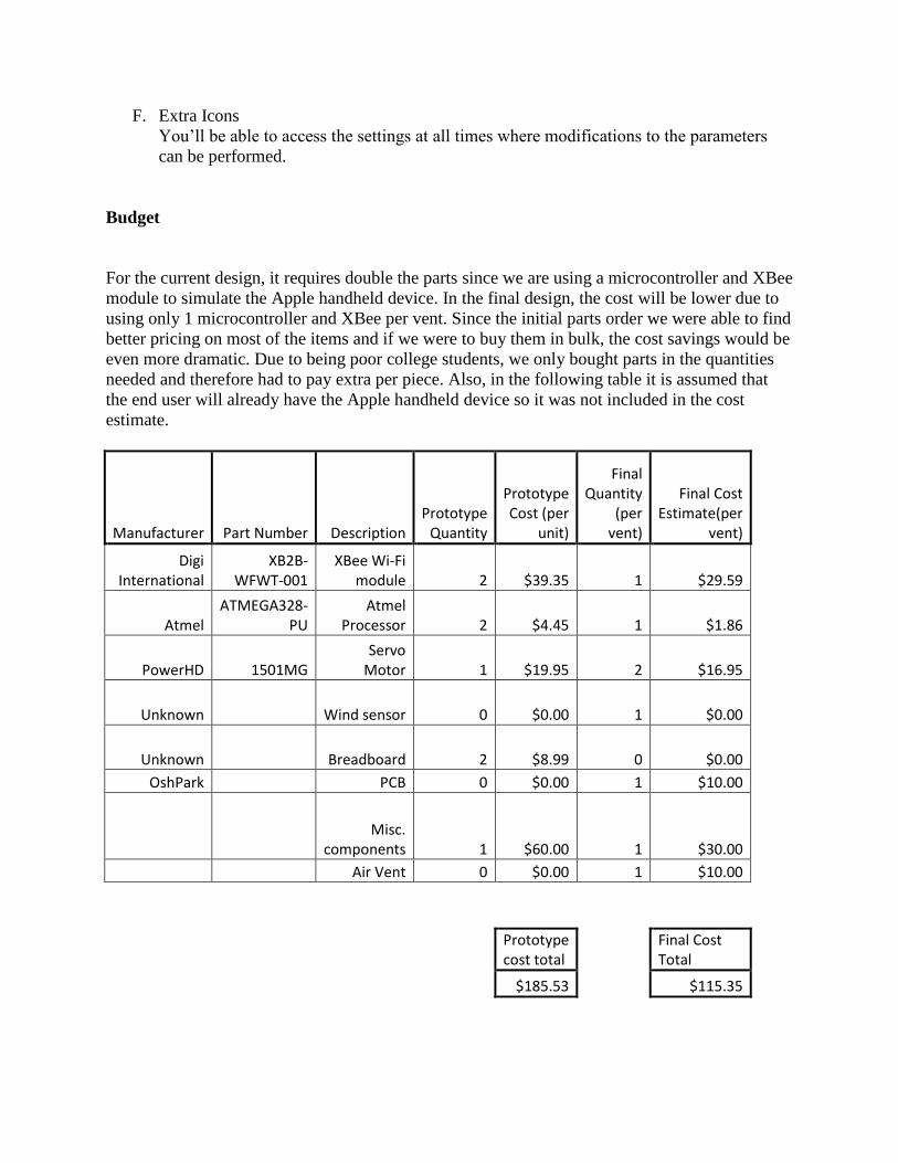
Budget
For the current design, it requires double the parts since we are using a microcontroller and XBee
module to simulate the Apple handheld device. In the final design, the cost will be lower due to
using only 1 microcontroller and XBee per vent. Since the initial parts order we were able to find
better pricing on most of the items and if we were to buy them in bulk, the cost savings would be
even more dramatic. Due to being poor college students, we only bought parts in the quantities
needed and therefore had to pay extra per piece. Also, in the following table it is assumed that
the end user will already have the Apple handheld device so it was not included in the cost
estimate.
Manufacturer Part Number Description Prototype
Quantity
Prototype Cost (per
unit)
Final Quantity
(per vent)
Final Cost Estimate(per
vent)
Digi International
XB2B-WFWT-001
XBee Wi-Fi module 2 $39.35 1 $29.59
Atmel ATMEGA328-
PU Atmel
Processor 2 $4.45 1 $1.86
PowerHD 1501MG Servo
Motor 1 $19.95 2 $16.95
Unknown Wind sensor 0 $0.00 1 $0.00
Unknown Breadboard 2 $8.99 0 $0.00
OshPark PCB 0 $0.00 1 $10.00
Misc.
components 1 $60.00 1 $30.00
Air Vent 0 $0.00 1 $10.00
Prototype cost total
Final Cost Total
$185.53
$115.35
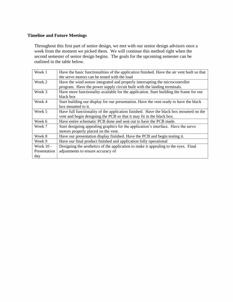
Timeline and Future Meetings
Throughout this first part of senior design, we met with our senior design advisors once a
week from the moment we picked them. We will continue this method right when the
second semester of senior design begins. The goals for the upcoming semester can be
outlined in the table below.
Week 1 Have the basic functionalities of the application finished. Have the air vent built so that
the servo motors can be tested with the load
Week 2 Have the wind sensor integrated and properly interrupting the microcontroller
program. Have the power supply circuit built with the landing terminals.
Week 3 Have more functionality available for the application. Start building the frame for our
black box
Week 4 Start building our display for our presentation. Have the vent ready to have the black
box mounted to it.
Week 5 Have full functionality of the application finished. Have the black box mounted on the
vent and begin designing the PCB so that it may fit in the black box.
Week 6 Have entire schematic PCB done and sent out to have the PCB made.
Week 7 Start designing appealing graphics for the application’s interface. Have the servo
motors properly placed on the vent.
Week 8 Have our presentation display finished. Have the PCB and begin testing it.
Week 9 Have our final product finished and application fully operational
Week 10 -
Presentation
day
Designing the aesthetics of the application to make it appealing to the eyes. Final
adjustments to ensure accuracy of