wireless network emulation system (wine) · wireless network emulation system (wine) gavin holland...
TRANSCRIPT
Wireless Network Emulation System (WiNE) Gavin Holland HRL Laboratories, LLC 3011 Malibu Canyon Road Malibu, CA 90265 March 30, 2005 Final Technical Report Contract No. MDA972-03-C-0061 June 2003 through March 2005
Sponsored By: Defense Advanced Research Projects Agency Advanced Technology Office (ATO) Program: Battlefield Damage Assessment ARPA Order No. Q013/00, Program Code: GS24E Issued by DARPA/CMO under Contract No. MDA972-03-C-0061 The views and conclusions contained in this document are those of the authors and should not be interpreted as representing the official policies, either expressly or implied, of the Defense Advanced Research Projects Agency or the U.S. Government.
Report Documentation Page Form ApprovedOMB No. 0704-0188
Public reporting burden for the collection of information is estimated to average 1 hour per response, including the time for reviewing instructions, searching existing data sources, gathering andmaintaining the data needed, and completing and reviewing the collection of information. Send comments regarding this burden estimate or any other aspect of this collection of information,including suggestions for reducing this burden, to Washington Headquarters Services, Directorate for Information Operations and Reports, 1215 Jefferson Davis Highway, Suite 1204, ArlingtonVA 22202-4302. Respondents should be aware that notwithstanding any other provision of law, no person shall be subject to a penalty for failing to comply with a collection of information if itdoes not display a currently valid OMB control number.
1. REPORT DATE 30 MAR 2005
2. REPORT TYPE N/A
3. DATES COVERED -
4. TITLE AND SUBTITLE Wireless Network Emulation System (WINE)
5a. CONTRACT NUMBER
5b. GRANT NUMBER
5c. PROGRAM ELEMENT NUMBER
6. AUTHOR(S) 5d. PROJECT NUMBER
5e. TASK NUMBER
5f. WORK UNIT NUMBER
7. PERFORMING ORGANIZATION NAME(S) AND ADDRESS(ES) Defense Advanced Research Projects Agency Advanced TechnologyOffice (ATO) Battlefield Damage Assessment Arlington, VA 22203-1714
8. PERFORMING ORGANIZATIONREPORT NUMBER
9. SPONSORING/MONITORING AGENCY NAME(S) AND ADDRESS(ES) 10. SPONSOR/MONITOR’S ACRONYM(S)
11. SPONSOR/MONITOR’S REPORT NUMBER(S)
12. DISTRIBUTION/AVAILABILITY STATEMENT Approved for public release, distribution unlimited
13. SUPPLEMENTARY NOTES The original document contains color images.
14. ABSTRACT
15. SUBJECT TERMS
16. SECURITY CLASSIFICATION OF: 17. LIMITATION OF ABSTRACT
UU
18. NUMBEROF PAGES
13
19a. NAME OFRESPONSIBLE PERSON
a. REPORT unclassified
b. ABSTRACT unclassified
c. THIS PAGE unclassified
Standard Form 298 (Rev. 8-98) Prescribed by ANSI Std Z39-18
1
Section 1
Introduction
1.1 Overview Costly decisions about which wireless networking technologies to develop are currently being based largely on results from high-level simulation tools. The FCS-C program, for instance, used high-level simulation tools to select the network and radio software for final development and demonstration. To mitigate risk, there needs to be lab-based tools that provide more accurate assessment than simulation but at far less cost than field testing. Our approach to this problem is to develop a tool that emulates a field-test environment in the lab, so technologies under consideration can migrate from coarse simulation models to actual code and tested “live,” in real-time, over a high-fidelity virtual wireless channel environment. Our current solution is the Wireless Network Emulator.
The Wireless Network Emulator (WiNE) is a network-embedded, highly-optimized, distributed simulation engine, built into a cluster of commodity workstations and switches. On each workstation, there appears to be one or more wireless network interfaces, located somewhere within a three-dimensional (virtual) environment. A packet sent across one of these interfaces experiences transmission errors according to the outcome of its simulated transmission in the virtual environment. Since the speed and fidelity of this process ultimately defines the quality of the emulation, WiNE employs novel techniques that exploit the availability of high-speed, low-latency programmable interconnects, fast processors, and large memories to minimize communication overhead and maximize simulation fidelity, while limiting the amount of induced latency and jitter. The last objective is important because induced latency and jitter can dramatically affect the performance of applications that require real-time QoS, such as audio and video streaming and teleoperation/telepresence control traffic, or rely on packet arrival time tracking for efficient operation, like TCP. WiNE’s unique design has the potential to reduce unwanted latency and jitter by several orders of magnitude below existing emulation platforms, like NistNet, Seawind, NS-Emulator, and QualNet’s Emulator, without any sacrifice in fidelity.
This report summarizes the development and testing that was conducted under this program. Notable achievements include the development of the first integrated prototype of the embedded distributed simulation engine, accompanied by a wonderful graphical user interface; and the development of detailed network, traffic, mobility, and environment models patterned after the FCS-C baseline field tests conducted at the Naval base in Lakehurst, NJ. Future work under consideration includes improvements in platform stability, support for HLA, new simulation models (specifically underwater and hybrid sensor networks), expanding the library of propagation, radio, and MAC models, and the development of a diverse set of virtual worlds.
1.2 Organization In Section 2 we present an overview of the WiNE architecture, which is followed in Section 3 by the results of our testing with the Lakehurst scenario. In Section 3 we summarize the report.
2
Section 2
WiNE Description
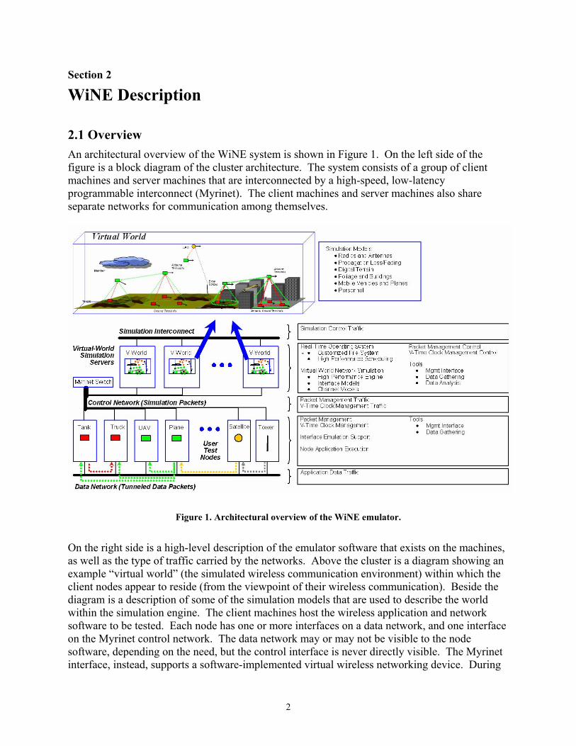
2.1 Overview An architectural overview of the WiNE system is shown in Figure 1. On the left side of the figure is a block diagram of the cluster architecture. The system consists of a group of client machines and server machines that are interconnected by a high-speed, low-latency programmable interconnect (Myrinet). The client machines and server machines also share separate networks for communication among themselves.
Figure 1. Architectural overview of the WiNE emulator.
On the right side is a high-level description of the emulator software that exists on the machines, as well as the type of traffic carried by the networks. Above the cluster is a diagram showing an example “virtual world” (the simulated wireless communication environment) within which the client nodes appear to reside (from the viewpoint of their wireless communication). Beside the diagram is a description of some of the simulation models that are used to describe the world within the simulation engine. The client machines host the wireless application and network software to be tested. Each node has one or more interfaces on a data network, and one interface on the Myrinet control network. The data network may or may not be visible to the node software, depending on the need, but the control interface is never directly visible. The Myrinet interface, instead, supports a software-implemented virtual wireless networking device. During
3
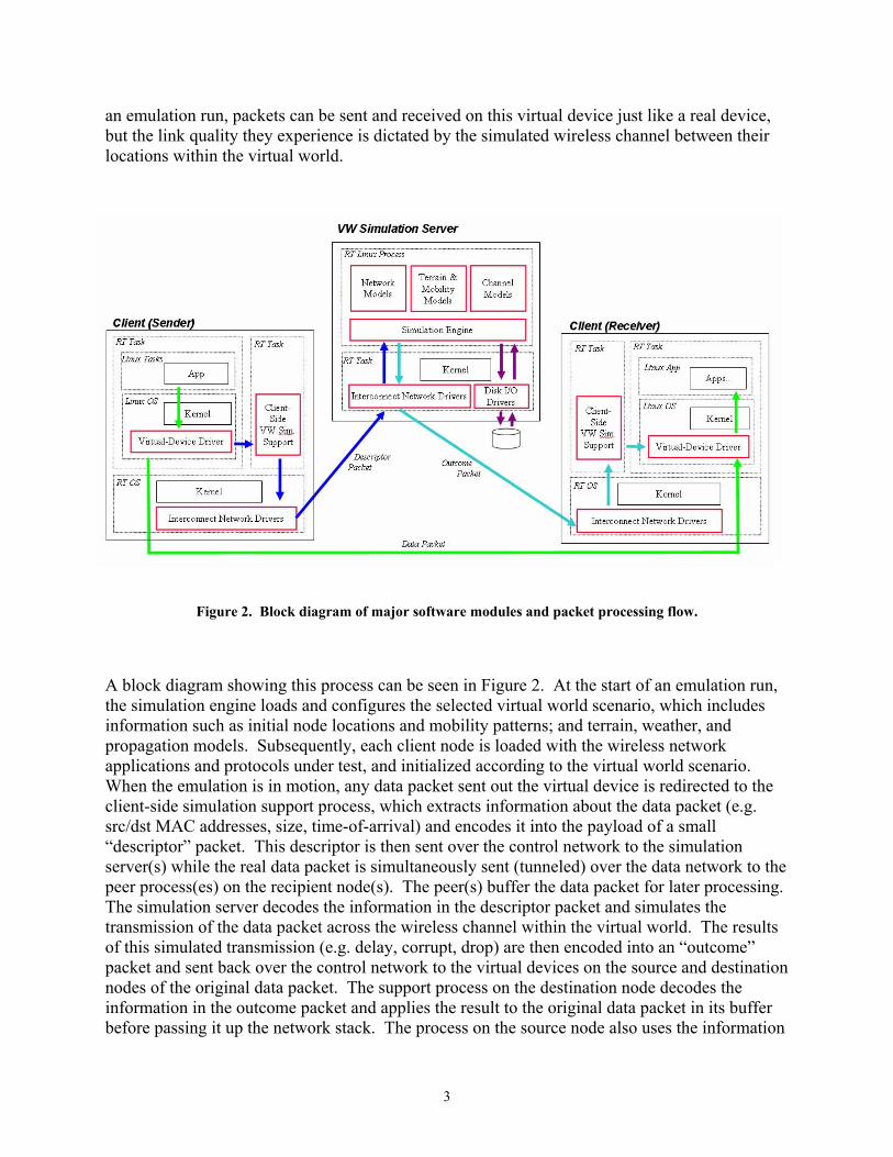
an emulation run, packets can be sent and received on this virtual device just like a real device, but the link quality they experience is dictated by the simulated wireless channel between their locations within the virtual world.
Figure 2. Block diagram of major software modules and packet processing flow.
A block diagram showing this process can be seen in Figure 2. At the start of an emulation run, the simulation engine loads and configures the selected virtual world scenario, which includes information such as initial node locations and mobility patterns; and terrain, weather, and propagation models. Subsequently, each client node is loaded with the wireless network applications and protocols under test, and initialized according to the virtual world scenario. When the emulation is in motion, any data packet sent out the virtual device is redirected to the client-side simulation support process, which extracts information about the data packet (e.g. src/dst MAC addresses, size, time-of-arrival) and encodes it into the payload of a small “descriptor” packet. This descriptor is then sent over the control network to the simulation server(s) while the real data packet is simultaneously sent (tunneled) over the data network to the peer process(es) on the recipient node(s). The peer(s) buffer the data packet for later processing. The simulation server decodes the information in the descriptor packet and simulates the transmission of the data packet across the wireless channel within the virtual world. The results of this simulated transmission (e.g. delay, corrupt, drop) are then encoded into an “outcome” packet and sent back over the control network to the virtual devices on the source and destination nodes of the original data packet. The support process on the destination node decodes the information in the outcome packet and applies the result to the original data packet in its buffer before passing it up the network stack. The process on the source node also uses the information

4
in the outcome to update the state of its virtual device (e.g. transmission statistics, queue status, transmission status).
In the sections that follow, we describe this system in more detail.
2.2 Virtual Wireless Network Interface The virtual wireless network interface is modeled partly on the client and partly in the virtual world simulation. The model of the wireless network interface can be broken down into separate data link layer models and physical layer models. The data link layer is further subdivided into two sublayers: Logical Link Control (LLC) and Media Access Control (MAC). The Logical Link Control (LLC) sublayer manages communications between devices over a "logical" link, whereas the Media Access Control (MAC) sublayer manages the communication across the physical link.
In the emulator, the data link layer model is divided between the client node and simulation server, with the LLC model residing entirely on the client. One reason for this separation is that there is little purpose for emulating the LLC, since it is designed to provide common access to different devices. Another reason is that there is a natural separation point in the system architecture between the MAC and LLC. The MAC is usually located in firmware on the network device and the LLC is located in the kernel, right above the device driver (which facilitates access to the hardware and firmware of the device by the kernel). Thus, separating the real system from the emulated system at the device driver level means we only have to emulate those portions of the network that are not easily manipulated within the lab environment.
The MAC models, however, are divided into a virtual hardware layer model and a simulation model. The virtual hardware layer is located within the virtual interface device driver on the client, and is responsible for maintaining the appearance of a physical network interface. The simulation object is located on the server, and contains the core functionality of the MAC. Communication between the two is carried in the descriptor and response packets across the emulation interconnect. A common API is currently being developed for this purpose, which will consist of a general set of core functions such as packet transfers, exception notifications, configuration status and change requests, and statistics gathering.
2.3 Virtual World Simulation Server The core of the emulator is a high-performance event-driven simulator. The simulator is built on a custom simulation engine that manages a set of software objects that mimic the behavior of components in the virtual network. Each software object is an instance of a model that reproduces the behavior of a real-world component. For example, wireless channel models mimic the behavior of the physical environment on the transmitted signal, such as pathloss, shadowing, and multipath fading; whereas network interface models mimic the components of the wireless device, such as the logical link control, the medium access control, and the radio.
The software objects are implemented as a set of extended finite state machines. State transitions are triggered by the handling of events from one of the simulation clocks. Example events are the expiration of a timer, the arrival of a packet, or a change in channel conditions. Terminal

5
states and select intermediate states may generate output, which can take the form of, for instance, packets, signals, or exceptions.
The main task of network object models is to simulate the exchange of packets with peer objects in the emulated network. Packets are represented by objects that are built by the sender from packet descriptors received from the virtual nodes. These packet objects are held until they are either transferred to another object or dropped. Other packet objects may be created and destroyed in the process, such as for control and management packets. Termination of any state machine, whether in error or success, always results in the generation of an outcome packet to the clients. Outcome packets may also be generated at any other time, for example, to "push" status information to the clients.
All inter-object communication is carried out strictly by the creation and handling of events at time offsets that accurately track the behavior of the actual protocol or device. This requirement maintains consistency between the virtual world and the real world by ensuring that events in the virtual world do not occur before those in the real world according to common global (wall-clock) time.
Hardware interfaces are too complex to model closely in software in a timely manner, so they are represented by high-level behavioral models that characterize the effects that the hardware architecture has on packet transmission and reception. Common, generic models are used to cover common architectural features, such as coding, modulation, and spreading techniques, whereas device specific models are used to cover traits unique to a specific device, such as proprietary protocols, noise factors, and sensitivity figures.
The wireless channel models consist of a single state machine that generates the loss or gain in received signal strength over a discrete time interval. The choice of time interval varies according to the channel model. For small-scale fading, the time interval is at least as small as the current coherence time of the channel. Interfering transmissions that arrive during an interval are handled by adding their partial energy contribution to the total interference for the interval.
The strength of a received radio signal depends on the propagation characteristics of the transmitted electromagnetic waves in the channel. The physical properties that govern these characteristics are incredibly diverse and complex. Thus, real-time computation of high-fidelity models is intractable for all but the simplest scenarios. Thus, we use a hybrid emulation approach. For low-fidelity emulation, we use high-level, computationally efficient statistical channel models that can be calculated during emulation. For higher-fidelity emulation, we use a combination of pre-computed (offline) channel conditions and statistical channel models.
Parameters for the wireless channel models can be obtained from the simulation of network interface positions within a three-dimensional terrain and node model. Currently, the server is able to construct terrain models from standard digital terrain files (e.g. DTED, GeoTiff, DEM), and node models from standard 3DS files. Additional support is provided for the modeling of obstruction blocks with varying attenuation affects.

6
2.4 Cluster Communication Cluster communication consists of a complex distributed real-time protocol that provides global clock synchronization and reliable communication across the emulation cluster. The heart of the core is a TDMA protocol that strictly regulates use of the communication channel, mitigating the impact of latency and jitter on the timeliness and accuracy of the emulation. To enable this functionality, the core is built, in part, from real-time RT-Linux kernel threads that operate beneath the non real-time Linux kernel. These real-time threads execute in synchrony across the cluster in a pattern defined by the TDMA protocol to exchange the control packets necessary to conduct the emulation. Some of these control packets are passed to/from non real-time threads in Linux through asynchronous interprocess communication mechanisms, requiring very careful coordination across threads to prevent race conditions that can disrupt communication flow.
2.5 Graphical User Interface A graphical user interface allows the user to control the emulator and visualize the virtual world. The interface communicates with the simulation server and control daemons residing on the clients. Example snapshots of the interface in action are shown on the following page.
2.6 Previous Work There have been a number of software emulators developed for modeling traffic congestion in wired networks (e.g. NIST Net [1], Dummynet [2], ONE [3], and Seawind [4]); most of these utilize device drivers or kernel modules to drop, delay, or corrupt packets according to some user defined probability distribution. A similar approach was used for the emulation of packet errors and congestion in a wireless network [5], except trace data from an actual wireless connection was used to perturb the flow of data packets. A different approach was taken in the ns-2 emulator [7], which emulates an entire mobile network, by simulating the network in ns-2 and then converting real data packets to simulated packets on the fly at the gateway node between the real and simulated networks. The gateway then reflects the outcome (e.g. dropped, delayed, corrupted) of the simulated version of a packet on the buffered real packet. Still other approaches, like that in [6], attempt to provide purely hardware solutions. Presently, WiNE is the only emulator that we are aware of that attempts to provide bounded, real-time emulation of a dynamic mobile networking environment at and below the LLC layer, enabling “live” testing of wireless networking protocols.

7
8
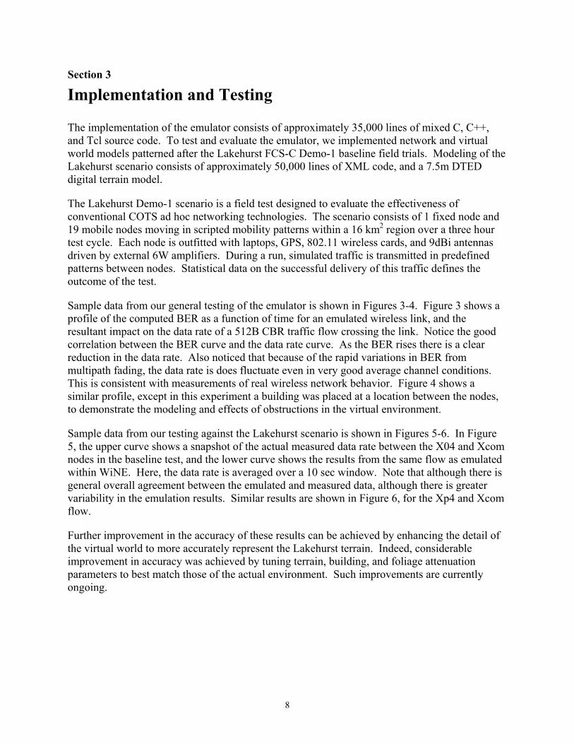
Section 3
Implementation and Testing
The implementation of the emulator consists of approximately 35,000 lines of mixed C, C++, and Tcl source code. To test and evaluate the emulator, we implemented network and virtual world models patterned after the Lakehurst FCS-C Demo-1 baseline field trials. Modeling of the Lakehurst scenario consists of approximately 50,000 lines of XML code, and a 7.5m DTED digital terrain model.
The Lakehurst Demo-1 scenario is a field test designed to evaluate the effectiveness of conventional COTS ad hoc networking technologies. The scenario consists of 1 fixed node and 19 mobile nodes moving in scripted mobility patterns within a 16 km2 region over a three hour test cycle. Each node is outfitted with laptops, GPS, 802.11 wireless cards, and 9dBi antennas driven by external 6W amplifiers. During a run, simulated traffic is transmitted in predefined patterns between nodes. Statistical data on the successful delivery of this traffic defines the outcome of the test.
Sample data from our general testing of the emulator is shown in Figures 3-4. Figure 3 shows a profile of the computed BER as a function of time for an emulated wireless link, and the resultant impact on the data rate of a 512B CBR traffic flow crossing the link. Notice the good correlation between the BER curve and the data rate curve. As the BER rises there is a clear reduction in the data rate. Also noticed that because of the rapid variations in BER from multipath fading, the data rate is does fluctuate even in very good average channel conditions. This is consistent with measurements of real wireless network behavior. Figure 4 shows a similar profile, except in this experiment a building was placed at a location between the nodes, to demonstrate the modeling and effects of obstructions in the virtual environment.
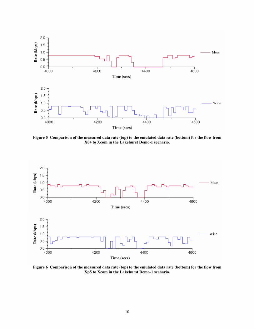
Sample data from our testing against the Lakehurst scenario is shown in Figures 5-6. In Figure 5, the upper curve shows a snapshot of the actual measured data rate between the X04 and Xcom nodes in the baseline test, and the lower curve shows the results from the same flow as emulated within WiNE. Here, the data rate is averaged over a 10 sec window. Note that although there is general overall agreement between the emulated and measured data, although there is greater variability in the emulation results. Similar results are shown in Figure 6, for the Xp4 and Xcom flow.
Further improvement in the accuracy of these results can be achieved by enhancing the detail of the virtual world to more accurately represent the Lakehurst terrain. Indeed, considerable improvement in accuracy was achieved by tuning terrain, building, and foliage attenuation parameters to best match those of the actual environment. Such improvements are currently ongoing.

9
Figure 3 Comparison of the emulated BER (top) and the induced affects on the link data rate (bottom).
Figure 4 Comparison of the emulated BER (top) and the link data rate (bottom) with an obstruction.
10
Figure 5 Comparison of the measured data rate (top) to the emulated data rate (bottom) for the flow from X04 to Xcom in the Lakehurst Demo-1 scenario.
Figure 6 Comparison of the measured data rate (top) to the emulated data rate (bottom) for the flow from Xp5 to Xcom in the Lakehurst Demo-1 scenario.

11
Section 4
Conclusion
Under this effort we implemented and successfully tested the first integrated prototype of the Wireless Network Emulator. Software components include an advanced, network embedded, distributed simulation engine, accompanied by a wonderful graphical user interface; and the development of detailed network, traffic, mobility, and environment models patterned after the FCS-C baseline field tests conducted at the Naval base in Lakehurst, NJ. Results of the Lakehurst tests demonstrate not only the correct operation of the emulator, but also demonstrate its accuracy in comparison to actual field data. In the future, we hope to continue our work with DARPA to develop the platform into a tool that can aid in the evaluation of a variety of wireless networking technologies. Additional planned enhancements include support for HLA federations, the addition of new simulation models (specifically underwater and hybrid sensor networks), and the expansion of the library of propagation, radio, and MAC models.
12
References [1] M. Carson, “Application and protocol testing through network emulation,” NIST, Internetworking and Technologies
Group, http://snad.ncsl.nist.gov/itg/nistnet/. [2] L. Rizzo. “Dummynet: A simple approach to the evaluation of network protocols,” ACM Computer Communication
Review, vol. 27, no. 1, pp. 31-41, Jan. 1997. [3] M. Allman, A. Caldwell, and S. Ostermann. “ONE: The Ohio network emulator.” Technical Report TR-19972, School of
Electrical Engineering and Computer Science, The Ohio University, Aug. 1997. [4] M. Kojo et al., “Seawind: A wireless network emulator,” in Proc. of MMB’01, 2001. [5] B. D. Noble, M. Satyanarayanan, G. T. Nguyen, and R. H. Katz, “Trace-based mobile network emulation,” in Proc. of
ACM SIGCOMM’97, Cannes, France, Sept. 1997. [6] J. T. Kaba and D. R. Raichle, “Testbed on a desktop: Strategies and techniques to support multi-hop MANET routing
protocol development,” in Proc. of MOBIHOC’01, pp. 164-172, 2001. [7] K. Fall, “Network emulation in the Vint/NS simulator,” in Proc. ISCC'99, July 1999.