wireless network emulation with
TRANSCRIPT

Ramon FontesChristian Rothenberg
1st edition2019
withWireless Network Emulation
withWireless Network Emulation
Ramon dos Reis FontesChristian Rodolfo Esteve Rothenberg
Wireless Network Emulation
with Mininet-WiFi
1st edition
CampinasChristian Rodolfo Esteve Rothenberg
2019
Credits
AuthorsRamon dos Reis FontesChristian Rodolfo Esteve Rothenberg
ReviewersMichel Daoud Yacoub
TemplateMathias Legrand ([email protected])modified by Vel ([email protected])under license CC BY-NC-SA 3.0:http://creativecommons.org/licenses/by-nc-sa/3.0/

About the authorsRamon dos Reis Fontes received the degree in Information Systems fromthe Faculty of Technology and Sciences (FTC), in 2009, the Master degreein Systems and Computing from Salvador University (UNIFACS), in 2013,and the Ph.D. degree in Electrical Engineering in the area of Computer En-gineering from the University of Campinas (UNICAMP), in 2018. His re-search interests includes Software-Defined Networking (SDN), wireless net-works, distributed systems, cloud and fog computing, Network FunctionsVirtualization (NFV), and security. Ramon has published several paperson conferences and journals, and has continuously contributed to the de-velopment of free and open source software through his Github account(https://github.com/ramonfontes). A variety of codes and instructionson how to reproduce his research works can be found at https://github.com/ramonfontes/reproducible-research/.
I would like to thank the readers for their interest in this book.Please do not hesitate to contact us if you need any help on anysubject covered in this book. I would like to thank my friends, col-leagues and teachers who have helped me in many ways. I wouldalso like to thank Prof. Dr. Christian Rothenberg, counselor,advisor and co-author of this book, for sharing his wisdom andencouragement throughout my career at the Faculty of ElectricalEngineering and Computing at UNICAMP.
My special thanks go to my beloved wife, Suian. This book wouldnot be a reality without your continued support. I would also liketo thank my parents, Helio and Conceição, for their incentivesand support.
To my daughter, Pietra, I dedicate this book.
Christian Rodolfo Esteve Rothenberg is Professor at the Department ofComputer Engineering and Industrial Automation (DCA) of the Faculty ofElectrical Engineering and Computation (FEEC) at the University of Camp-inas (UNICAMP) since 2013. He holds the Telecommunication Engineering
degree from the Technical University of Madrid (ETSIT - UPM), Spain, theM.Sc. (Dipl. Ing.) degree in Electrical Engineering and Information Tech-nology from Darmstadt University of Technology (TUD), Germany, 2006,and the Ph.D. in Electrical Engineering from UNICAMP (2010). From 2010to 2013, he worked as a senior researcher at CPqD R&D center in telecom-munication on P&D projects in the area of IP platforms. He is the Princi-pal Investigator of the Information & Networking Technologies Research &Innovation Group (INTRIG – https://intrig.dca.fee.unicamp.br/),CNPq Research Productivity Fellow level 2 (2017-2020), and CNPq Techno-logical Development and Innovative Extension Fellow level 2 (2014-2016).His research interests include computer network architectures, virtualiza-tion, cloud computing, SDN, NFV, among others. He has 2 internationalpatents and more than 120 magazine and conference publications, accu-mulating more than 6000 citations (h-index: 28, i10-index: 50+, https://scholar.google.com.br/citations?user=8PxuHPkAAAAJ&hl=en).
The completion of a book is a great opportunity to reflect andexpress gratitude. Starting with our ancestors, in my case, myparents José Luis and Ana. In my academic life, I I thank all theteachers who influenced me with a special highlight to ProfessorMauricio, PhD advisor, academic father, and friend, a key figuresince I landed on this beloved Brazil. I am grateful for all theopportunities I have received from this country, its people, andinstitutions, including CPqD, FEEC, UNICAMP, the nationalfunding agencies CNPq and FAPESP, Ericsson, among others. Ithank students, from undergraduate to postgraduate, professionalcolleagues, and friends of everyday life. To our INTRIG group,and of course, to Prof. Dr. Ramon Fontes, the first PhD madein INTRIG, an example of graduate student and human being,father and co-author of this book that I am sure will contribute tothe formation of more professionals. Finally, the most importantvector in life, the family, my wife Marcela, my children Gabrieland Marina, my sources of energy and happiness. Thank you!

About the Reviewers
Daniel Senna
We would like to thank Daniel Senna, an editor at Textual Asses-soria, for providing proofreading assistance.

AcknowledgementsThe success of this project and the writing of this book were only possiblethanks to the support, collaboration and trust of many people and institutionsthat helped to make them come true. Therefore, we would like to record ourthanks.
We thank Katia Obraczka, professor at the University of California, SantaCruz, California, for his valuable input and suggestions on Mininet-WiFidevelopment steps. We also thank the Institut National de Recherche enInformatique et en Automatique (INRIA), especially to Thierry Turlettiand Walid Dabbous, for receiving us at INRIA for six (6) months and forcontributing in various aspects related to the development of Mininet-WiFi.For the financial support, we thank the Fundação de Amparo à Pesquisa doEstado de São Paulo (FAPESP), process 2014/18482-4 and Conselho Na-cional de Pesquisas (CNPq), process 310930/2016-2. The INTRIG researchgroup thanks Ericsson for the research funding received, without which thegroup would not have achieved its results, many of them leveraged by andcontributing to Mininet-WiFi.
Thanks also to users, researchers, and/or developers who contributed to mak-ing this book a reality, more specifically: Prof. Dr. Chih-Heng Ke, fromthe National Quemoy University/Taiwan, for tips and shared experience onhow wireless networks work; Brian Linkletter, for writing a tutorial, andhelping spread Mininet-WiFi; Patrick Große, for developing a Wmediumdextension for Mininet-WiFi; and, of course, to the Mininet-WiFi communityfor all discussions that result in the development of an increasingly stable andcomplete emulator in terms of features supported.
Wireless Network Emulation with Mininet-WiFiISBN: 978-65-900571-5-0 (E-book)
Terms & Conditions
All rights reserved.No part of this work may be copied or reproduced in any form or by anymeans, electronically, photocopying, recording, etc. without the expresswritten permission of the authors and copyright holders.

Table of Contents
List of Figures iii
List of Tables v
List of Acronyms viii
I Introduction
1 Background . . . . . . . . . . . . . . . . . . . . . . . . . . . . . . . . . . . . 3
1.1 Wireless communications 3
1.2 WiFi: IEEE 802.11-based wireless local area networks 5
1.3 Software-defined wireless networking 10
1.4 Mininet-WiFi 13
1.4.1 Architecture . . . . . . . . . . . . . . . . . . . . . . . . . . . . . . . . . . . . . 15
1.4.2 Components . . . . . . . . . . . . . . . . . . . . . . . . . . . . . . . . . . . . 16

II Level: beginner
2 Beginner . . . . . . . . . . . . . . . . . . . . . . . . . . . . . . . . . . . . . . 21
2.1 Downloading and installing Mininet-WiFi 21
2.2 First steps to use Mininet-WiFi 23
2.3 Customizing topologies 30
2.4 Accessing node information 32
2.5 OVSAP versus UserAP 34
2.6 Graphical User Interface (GUI) 372.6.1 Visual Network Descriptor . . . . . . . . . . . . . . . . . . . . . . . . . . 372.6.2 MiniEdit . . . . . . . . . . . . . . . . . . . . . . . . . . . . . . . . . . . . . . . . . 392.6.3 Viewing 2D and 3D graphics . . . . . . . . . . . . . . . . . . . . . . . . 40
2.7 Wireless network emulation 422.7.1 TC (Traffic Control) . . . . . . . . . . . . . . . . . . . . . . . . . . . . . . . . 422.7.2 Wmediumd . . . . . . . . . . . . . . . . . . . . . . . . . . . . . . . . . . . . . 432.7.3 TC versus Wmediumd in practice . . . . . . . . . . . . . . . . . . . . 44
2.8 Propagation model 472.8.1 Providing more realism . . . . . . . . . . . . . . . . . . . . . . . . . . . . . 49
2.9 Distance versus received signal 50
2.10 Modifying bitrate 52
2.11 Distance versus throughput 54
2.12 Mobility models 56
III Level: intermediate
3 Intermediate . . . . . . . . . . . . . . . . . . . . . . . . . . . . . . . . . . 61
3.1 Network interfaces 613.1.1 Setting multiple interfaces . . . . . . . . . . . . . . . . . . . . . . . . . . 623.1.2 Binding interfaces . . . . . . . . . . . . . . . . . . . . . . . . . . . . . . . . 643.1.3 Bonding interfaces . . . . . . . . . . . . . . . . . . . . . . . . . . . . . . . . 65
3.2 Traffic analysis 703.2.1 Capturing packets . . . . . . . . . . . . . . . . . . . . . . . . . . . . . . . . 703.2.2 Capturing beacons . . . . . . . . . . . . . . . . . . . . . . . . . . . . . . . 733.2.3 Spectrum analysis . . . . . . . . . . . . . . . . . . . . . . . . . . . . . . . . 753.2.4 Network telemetry . . . . . . . . . . . . . . . . . . . . . . . . . . . . . . . . 78
3.3 Scanning methods 803.3.1 Active scanning . . . . . . . . . . . . . . . . . . . . . . . . . . . . . . . . . . 803.3.2 Passive scanning . . . . . . . . . . . . . . . . . . . . . . . . . . . . . . . . . 80
3.4 Wireless mesh and ad hoc 833.5 OpenFlow protocol 873.5.1 Capturing OpenFlow messages . . . . . . . . . . . . . . . . . . . . . 883.5.2 Creating flows . . . . . . . . . . . . . . . . . . . . . . . . . . . . . . . . . . . 913.5.3 OpenFlow and wireless networks . . . . . . . . . . . . . . . . . . . . . 933.5.4 Remote controller . . . . . . . . . . . . . . . . . . . . . . . . . . . . . . . . 963.5.5 OpenFlow and handover . . . . . . . . . . . . . . . . . . . . . . . . . . 98
3.6 Use case scenarios 1023.6.1 WEB server . . . . . . . . . . . . . . . . . . . . . . . . . . . . . . . . . . . . . 1023.6.2 DHCP server . . . . . . . . . . . . . . . . . . . . . . . . . . . . . . . . . . . . 1043.6.3 Dealing with loops . . . . . . . . . . . . . . . . . . . . . . . . . . . . . . . 1083.6.4 Virtual LAN (VLAN) . . . . . . . . . . . . . . . . . . . . . . . . . . . . . . . 1113.6.5 Routing . . . . . . . . . . . . . . . . . . . . . . . . . . . . . . . . . . . . . . . 1153.6.6 Firewall . . . . . . . . . . . . . . . . . . . . . . . . . . . . . . . . . . . . . . . . 1183.6.7 Quality of Service (QoS) . . . . . . . . . . . . . . . . . . . . . . . . . . 1223.6.8 MultiPath TCP (MP-TCP) . . . . . . . . . . . . . . . . . . . . . . . . . . . 124
IV Level: expert
4 Expert . . . . . . . . . . . . . . . . . . . . . . . . . . . . . . . . . . . . . . . . 131
4.1 Manipulating kernel modules 1314.2 Traffic monitoring with sFlow-RT 1354.3 Reproducing network behavior 1374.3.1 Network attributes . . . . . . . . . . . . . . . . . . . . . . . . . . . . . . . 1374.3.2 Mobility . . . . . . . . . . . . . . . . . . . . . . . . . . . . . . . . . . . . . . . 138

4.4 Socket - low-level networking interface 1394.5 P4 1404.5.1 Differences between P4 and OpenFlow . . . . . . . . . . . . . . 1414.5.2 Basic WiFi scenario . . . . . . . . . . . . . . . . . . . . . . . . . . . . . . . 1424.5.3 Handover . . . . . . . . . . . . . . . . . . . . . . . . . . . . . . . . . . . . . . 1434.5.4 Dropping packets based on BSSID . . . . . . . . . . . . . . . . . . 145
4.6 Use case scenarios 1474.6.1 Containers . . . . . . . . . . . . . . . . . . . . . . . . . . . . . . . . . . . . . 1474.6.2 Interaction between virtual and real environments . . . . . 1494.6.3 Decoding packets . . . . . . . . . . . . . . . . . . . . . . . . . . . . . . . 1584.6.4 Association control . . . . . . . . . . . . . . . . . . . . . . . . . . . . . . 1654.6.5 Forwarding by SSID . . . . . . . . . . . . . . . . . . . . . . . . . . . . . . 1664.6.6 Security . . . . . . . . . . . . . . . . . . . . . . . . . . . . . . . . . . . . . . . 1694.6.7 6LoWPAN / IoT . . . . . . . . . . . . . . . . . . . . . . . . . . . . . . . . . . 1844.6.8 Vehicular ad hoc networks . . . . . . . . . . . . . . . . . . . . . . . . 189
FAQ
FAQ . . . . . . . . . . . . . . . . . . . . . . . . . . . . . . . . . . . . . . . . . . 197
References
References . . . . . . . . . . . . . . . . . . . . . . . . . . . . . . . . . . . 203

Preface
We are witnessing an impressive revolution in the field of Computer Networks.Advances in wireless communications such as the imminent deployment of5G networks worldwide, the ability to virtualize network infrastructures (e.g.Network Slicing and Network Function Virtualization) and to program theirbehavior (e.g. Software-Defined Networking) are concrete examples of thisnew era.
These advances enable the design, development and deployment of innovativemechanisms aimed at, for instance, higher resilience, performance, energy ef-ficiency, and security of the network and service ecosystem. A key element toexplore these new opportunities is the use of tools that enable prototyping andtesting novel ideas at an early stage, without the constraints and complexitiesassociated with employing a real infrastructure. This is precisely the role occu-pied by Mininet-WiFi, an environment that allows one to create, explore andexperiment with software-defined wireless networks from a personal computer.
As an instructor of the Undergraduate and Graduate Networking courses atINF-UFRGS, I often assign students to develop new mechanisms on software-defined network infrastructures. It was a pleasant surprise when, in 2016, Ibegan using Mininet-WiFi. This environment has dramatically expanded thescope of possible work we could do, enabling us to design a whole new setof proposals, such as routing algorithms for efficient mobile video stream-ing, handoff strategies with traffic fluctuation awareness and load balancingmechanisms. This type of work was challenging, if not impossible, to carryout in the classic Mininet environment, as it was beyond its scope to provideprimitives for dealing specifically with wireless communication.
This book closes a cycle of development, innovation and transfer of newknowledge to society. By very didactically documenting and explaining howto use Mininet-WiFi through scripts, example codes, illustrations and otherresources, the book will foster many new experiences like the ones just men-tioned. There is no doubt that it will endure as an important work in theacademic, industry and government sectors. I congratulate the authors fortheir praiseworthy initiative of advancing knowledge in this fascinating and

fundamental field. There is no time to waste: the time has come to "roll up oursleeves" and begin our immersion in Mininet-WiFi. Good reading and enjoy!
Prof. Luciano Paschoal GasparyInstitute of Informatics - UFRGS

Chapter Organization
This book is organized as follows:
Chapter I introduces theoretical fundamentals of wireless networks, software-defined wireless networks and also Mininet-WiFi. This chapter goes in-depthinto concepts relevant to the learning objectives of this book. For a deeperunderstanding of the different topics explored, the reader will be providedreferences to relevant literature in the field;
Chapter II introduces the beginner level of Mininet-WiFi proficiency andis devoted solely to providing the working details of Mininet-WiFi, whereits key functional aspects are described. If you are already proficient withMininet-WiFi, you can focus on chapters III and IV instead. You do not needto be familiar with Mininet to use Mininet-WiFi, but if you are, you willcertainly have a smoother feel as to how Mininet-WiFi works. The tutorialsincluded in this chapter can be used as complementary activities in theoryclasses at the undergraduate level (e.g. EA074 at FEEC/UNICAMP), as wellas in practical laboratory courses (e.g. EA080 at FEEC/UNICAMP);
Chapter III introduces the intermediate level of Mininet-WiFi proficiency,covers tutorials that employ wireless networking, software-defined wirelessnetworking, as well as a number of concepts related to computer networking.This chapter also describes the use of some network applications, such astcpdump and Wireshark. In addition to meeting the pedagogical goals ofmore advanced computer network classes such as those involving laboratoryactivities, the tutorials in this chapter are also suitable for graduate classes(e.g. IA369, IA376 at FEEC/UNICAMP) and specialization courses (e.g.INF-556 at IC/UNICAMP), as they allow experimental research to be carriedin more complex scenarios, such as the development of SDN solutions usingthe OpenFlow protocol;
Finally, Chapter IV introduces the expert level of Mininet-WiFi proficiency,has tutorials about kernel manipulation, containers, security, IoT, vehicularnetworks, etc., with valuable information on adapting the OpenFlow protocolto wireless networks. This chapter is labeled as advanced because it requires
more in-depth knowledge and the use of third-party applications. Therefore,the tutorials in this chapter are best suited for specialization and graduatecourses, not only in classes but also as technical training for master’s and doc-toral students, thus helping the development of experimental research aimed atadvancing the state of the art. However, nothing prevents curious readers fromreproducing these tutorials, since they have similar walkthroughs, as well asthe support provided by the codes from the previous chapters.
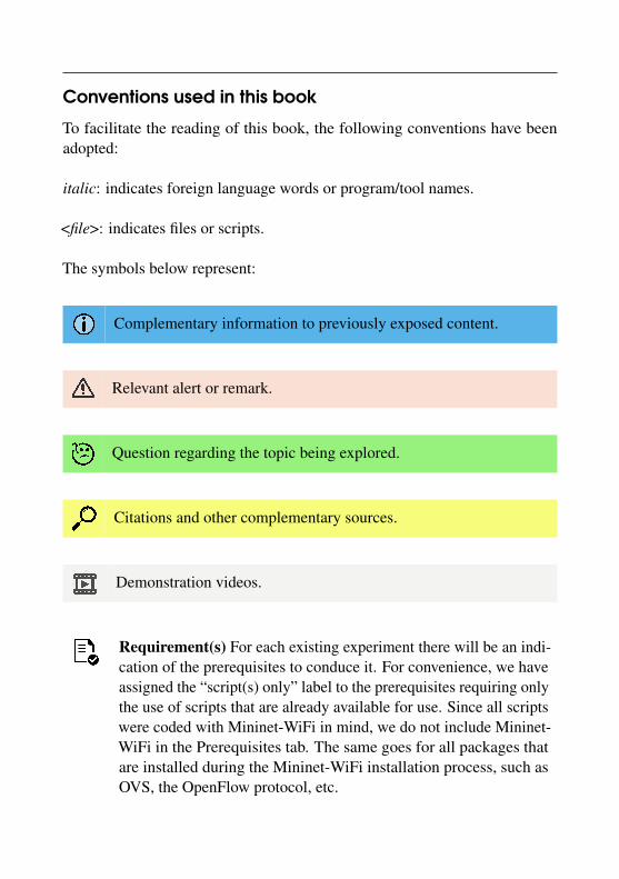
Conventions used in this book
To facilitate the reading of this book, the following conventions have beenadopted:
italic: indicates foreign language words or program/tool names.
<file>: indicates files or scripts.
The symbols below represent:
Complementary information to previously exposed content.
Relevant alert or remark.
Question regarding the topic being explored.
Citations and other complementary sources.
Demonstration videos.
Requirement(s) For each existing experiment there will be an indi-cation of the prerequisites to conduce it. For convenience, we haveassigned the “script(s) only” label to the prerequisites requiring onlythe use of scripts that are already available for use. Since all scriptswere coded with Mininet-WiFi in mind, we do not include Mininet-WiFi in the Prerequisites tab. The same goes for all packages thatare installed during the Mininet-WiFi installation process, such asOVS, the OpenFlow protocol, etc.

Other conventionsAs there is a tendency to replace tools from the net-tools package by those ofthe iproute2 package in Linux operating systems, network tools like iw andip are preferred for the tutorials. Nonetheless, programs from the net-toolspackage can also be used.
Finally, due to code update issues all scripts are available in a repositoryon Github (https://github.com/ramonfontes/mn-wifi-book-en).

Precautions
It is recommended that all tutorials available in this book be completed usingthe latest version of Mininet-WiFi available on Github. Should you, the reader,find any inconsistencies in the tutorials, you may contact the authors of thisbook at any time for clarification.
Although this book brings hands-on experience at all times, we recommendthat you review each command or configuration beforehand so that the entireprocess can be understood.Do not try to complete the tutorials without clearly understanding whatis being done!
I must use Linux. But why?Because the code base of Mininet-WiFi, Mininet, was developed for Linuxsystems. The development of Mininet-WiFi has maintained the same operatingstructure as that of Mininet. The Ubuntu operating system should be preferred,especially its Long Term Support (LTS) versions, as they are the most stableUbuntu distributions.
Why open source code?
We will answer this question with a simple answer: because most of the timewe (you, I and everyone) have the freedom to use the tool/program we want.Whether it is because we need to do work or academic research, or because wewant to know more about Mininet-WiFi, or even because we need to modify itto suit our needs, we can choose. However, this seems like a ready answer,which we often receive as an answer by others when we wonder about theadvantages of opening the source code of a particular program.
Arguing chronologically, we could say that without Mininet-WiFi, I, Ra-mon, would not have obtained a doctoral degree; many researchers would nothave done their research; Mininet, the emulator Mininet-WiFi was based on,would probably not exist either, and so on. What we mean is that without opensource philosophy, we would not have access to Mininet and would not havedeveloped Mininet-WiFi. Just as Mininet would not have been developed with-
out the previous development of its backbone and its subsequent availabilityfor anyone to use. Most likely you would not even be reading this book nowand many fewer persons would be interested in the subjects we covered in it.
Can you imagine how much research on other topics would be undermined byonly focusing on the field of research covered in this book and ignoring otherpossibilities? Perhaps you will have a better idea as you complete the tutorialsproposed throughout this book.
There is a whole chain that would be seriously impacted if the codes werenot free to use. The main paper [14] about Mininet alone has had about 1500direct citations, not to mention countless indirect citations by blogs and eventhe media.
Experiences: Impact, Reproducibility and Quality
If you are wondering whether it is worth researching and exposing your codeto the public, even though it is still in the early stages of development, hereare some reports of experiences we have gained throughout Mininet-WiFidevelopment.
Impact. Making code, data, documentation and demonstration videos publichas certainly contributed and still greatly contributes to increasing Mininet-WiFi’s visibility. Although there has been no systematic and qualitative assess-ment of the Mininet-WiFi community, users have contributed to the projectseveral times, whether by discussing or even suggesting code improvementsand new implementations.
Reproducibility. Making data public and reproducible is not always a simpletask. By the way, writing a book whose tutorials users can complete withoutany setbacks is not easy. Most likely there will be one or another tutorial thatwill not flow as expected. This is due to several factors, such as differences intool versions, issues that may be related to the operating system, hardware, etc.Throughout the development of Mininet-WiFi, we had a hard time reproducingexperiments by other researchers, as there was often not enough informationto do so. For this reason, we have chosen not only to make our experiments

public, but also to describe how they can be reproduced. Making researchreproducible generally adds credibility to its respective work and obtainedresults.
Quality. In a broader sense of research quality, all the experiences gainedthroughout the development of Mininet-WiFi allowed us to learn and refineour research. Although ensuring the reproducibility of a project increasesworkload, reproducible work has a number of significant advantages, such as:(i) synergy with open source functionality, as the latter increases the chances ofdirect and indirect reproducibility and, consequently, (ii) greater impact, sincethe chances of researchers using the solutions proposed by reproducible worksincrease; (iii) improvement of programming habits, wherein special attentionis given to code quality; (iv) encouragement of the use of scientific workflows,as researchers are carefully concerned with providing reliable results so thatanyone can produce results similar to those they have obtained.
So if you have the opportunity, and if your code is not a license, patent,or any other copyrighted content, try making your code public!

List of Figures
1.1 RSSI . . . . . . . . . . . . . . . . . . . . . . . . . . . . . . . . . . . . . . . . . . . . . . 41.2 Effect of path loss. . . . . . . . . . . . . . . . . . . . . . . . . . . . . . . . . . 51.3 IEEE 802.11 modes. . . . . . . . . . . . . . . . . . . . . . . . . . . . . . . . . . 61.4 IEEE 802.11b channels . . . . . . . . . . . . . . . . . . . . . . . . . . . . . . 71.5 infrastructure. . . . . . . . . . . . . . . . . . . . . . . . . . . . . . . . . . . . . . 81.6 ad hoc. . . . . . . . . . . . . . . . . . . . . . . . . . . . . . . . . . . . . . . . . . . 81.7 IEEE 802.11 frame header. . . . . . . . . . . . . . . . . . . . . . . . . . . . 91.8 High-level and generic architecture for SDWN . . . . . . . . 111.9 Experimental platforms for wireless networks . . . . . . . . . . 141.10 Mininet-WiFi architecture . . . . . . . . . . . . . . . . . . . . . . . . . 151.11 Main components of Mininet-WiFi . . . . . . . . . . . . . . . . . . 16
2.1 Simple topology. . . . . . . . . . . . . . . . . . . . . . . . . . . . . . . . . . . 242.2 Executing xterm. . . . . . . . . . . . . . . . . . . . . . . . . . . . . . . . . . 292.3 Single topology. . . . . . . . . . . . . . . . . . . . . . . . . . . . . . . . . . . 31
ii LIST OF FIGURES
2.4 Linear topology. . . . . . . . . . . . . . . . . . . . . . . . . . . . . . . . . . . 32
2.5 Visual Network Descriptor. . . . . . . . . . . . . . . . . . . . . . . . . . 38
2.6 Miniedit. . . . . . . . . . . . . . . . . . . . . . . . . . . . . . . . . . . . . . . . . . 39
2.7 2D Graphic. . . . . . . . . . . . . . . . . . . . . . . . . . . . . . . . . . . . . . 41
2.8 3D Graphic. . . . . . . . . . . . . . . . . . . . . . . . . . . . . . . . . . . . . . 41
2.9 Working with mobility. . . . . . . . . . . . . . . . . . . . . . . . . . . . . . 57
3.1 Bonding interface. . . . . . . . . . . . . . . . . . . . . . . . . . . . . . . . . 66
3.2 Packets captured . . . . . . . . . . . . . . . . . . . . . . . . . . . . . . . . 71
3.3 Captured beacons . . . . . . . . . . . . . . . . . . . . . . . . . . . . . . . 74
3.4 linssid capture screen with two access points. . . . . . . . . 76
3.5 Signal overlapping. . . . . . . . . . . . . . . . . . . . . . . . . . . . . . . . 76
3.6 linssid capture screen with three access points . . . . . . . 77
3.7 Captured beacons . . . . . . . . . . . . . . . . . . . . . . . . . . . . . . . 79
3.8 Ad hoc and mesh topology. . . . . . . . . . . . . . . . . . . . . . . . 83
3.9 OpenFlow message capture. . . . . . . . . . . . . . . . . . . . . . . 89
3.10 Communication between switch and controller. . . . . . 90
3.11 Handover topology. . . . . . . . . . . . . . . . . . . . . . . . . . . . . . . 99
3.12 DHCP Server topology. . . . . . . . . . . . . . . . . . . . . . . . . . . 105
3.13 Interface sta1-wlan0 . . . . . . . . . . . . . . . . . . . . . . . . . . . . 107
3.14 DHCP Server running. . . . . . . . . . . . . . . . . . . . . . . . . . . . 108
3.15 Switching loop topology. . . . . . . . . . . . . . . . . . . . . . . . . 109
3.16 VLANs topology. . . . . . . . . . . . . . . . . . . . . . . . . . . . . . . . . 112
3.17 VLAN ID . . . . . . . . . . . . . . . . . . . . . . . . . . . . . . . . . . . . . . . 113
3.18 Static routing topology. . . . . . . . . . . . . . . . . . . . . . . . . . . 116
3.19 Dynamic routing topology. . . . . . . . . . . . . . . . . . . . . . . . 118
3.20 QoS topology. . . . . . . . . . . . . . . . . . . . . . . . . . . . . . . . . . . 122
3.21 MP-TCP Kernel. . . . . . . . . . . . . . . . . . . . . . . . . . . . . . . . . . 125
4.1 sFlow-RT. . . . . . . . . . . . . . . . . . . . . . . . . . . . . . . . . . . . . . . . . 137

LIST OF FIGURES iii
4.2 Basic WiFi scenario. . . . . . . . . . . . . . . . . . . . . . . . . . . . . . . 1424.3 Handover scenario. . . . . . . . . . . . . . . . . . . . . . . . . . . . . . . 1444.4 BSSID based scenario. . . . . . . . . . . . . . . . . . . . . . . . . . . . . 1464.5 Internet topology. . . . . . . . . . . . . . . . . . . . . . . . . . . . . . . . 1534.6 WiFi network card connected to laptop. . . . . . . . . . . . . 1554.7 Interaction with physical nodes topology. . . . . . . . . . . . 1574.8 Packets sent by sta1 and sta2 . . . . . . . . . . . . . . . . . . . . . 1644.9 Forwarding by SSID. . . . . . . . . . . . . . . . . . . . . . . . . . . . . . . 1674.10 ARP spoofing attack. . . . . . . . . . . . . . . . . . . . . . . . . . . . . 1694.11 The four-way handshake. . . . . . . . . . . . . . . . . . . . . . . . . 1744.12 Snort . . . . . . . . . . . . . . . . . . . . . . . . . . . . . . . . . . . . . . . . . . 1784.13 Capturing RADIUS protocol messages. . . . . . . . . . . . . . 1814.14 RADIUS topology. . . . . . . . . . . . . . . . . . . . . . . . . . . . . . . . 1834.15 Nodes connected via 6LoWPAN. . . . . . . . . . . . . . . . . . 1854.16 6LoWPAN packets. . . . . . . . . . . . . . . . . . . . . . . . . . . . . . . 1864.17 Simulation of Urban MObility (SUMO). . . . . . . . . . . . . . . 190


List of Tables
1.1 Comparing IEEE 802.11 modes . . . . . . . . . . . . . . . . . . . . . . 71.2 IEEE 802.11n and IEEE 802.11ac comparison . . . . . . . . . . . 8


List of Acronyms
6LoWPAN IPv6 over Low power Wireless Personal Area Networks
AP Access Point
BER Bit Error Rate
BOFUSS Basic OpenFlow User-space Software Switch
BSS Basic Service Set
CAPWAP Control and Provisioning of Wireless Access Points
CD Collision Detection
CSMA/CA Carrier Sense Multiple Access with Collision Avoidance
Hostapd Host Access Point Daemon
HTTPS Hyper Text Transfer Protocol Secure
IBSS Independent Basic Service Set
IDS Intrusion Detection System
IFB Intermediate Functional Block

viii LIST OF ACRONYMS
IoT Internet of Things
LTE Long-Term Evolution
LWAPP Lightweight Access Point Protocol
MCS Modulation and Coding Scheme
MIMO Multiple Input, Multiple Output
MLME Media Access Control Sublayer Management Entity
MPTCP MultiPath TCP
MQTT Message Queuing Telemetry Transport
NFV Network Function Virtualization
OF OpenFlow
ONF Open Networking Foundation
OVSAP OpenvSwitch Access Point
RSSI Received Signal Strength Indicator
RTC Request To Receive
RTS Request To Send
SDN Software Defined Networking
SDWN Software Defined Wireless Networking
SNR Signal to Noise Ratio
SSID Service Set Identifier
STA Station
SUMO Simulation of Urban MObility
TC Traffic Control
UserAP User level Access Point
VANET Vehicular Ad hoc NETwork
WLAN Wireless Local Area Network

I1 Background . . . . . . . . . . . . . . . . . . . . . . . . . . 31.1 Wireless communications1.2 WiFi: IEEE 802.11-based wireless local area networks1.3 Software-defined wireless networking1.4 Mininet-WiFi
Introduction

1. Background
1.1 Wireless communications
Wireless communications continues to be one of the most vibrant fields in thetelecommunications sector. Although they began in the late nineteenth andearly twentieth centuries, wireless communication research and developmentactivities intensified between the 1970s to 1990s, fueled by a growing demandfor increasingly better connectivity. Initially driven by the development of cellphones for voice services and then data applications, wireless technologieskeep evolving, fostered by new forms of content creation and consumptionand interaction between humans, machines and everyday objects, a trendcommonly known as the Internet of Things (IoT).
Conventional wireless communication networks encompass several elements,the most basic of which are listed below: (i) the wireless terminals - suchas laptops, smartphones, which are the interface between the user and thenetwork; (ii) radio links, which connect the terminals to an agent providing thenetwork coverage service; (iii) base stations, which function as the coverageagents; (iv) switching and control centers, which concentrate the base stations
4 Background
and connect them to other communication services.
There are numerous technologies that provide wireless services, such as Blue-tooth, LTE, Zigbee, WiFi, among other means. Wireless communicationshave unique features that make them distinct from other technologies. Oneof them, and certainly the most important one, is the propagation of radiowaves. A signal propagating from one point to another undergoes three typesof phenomena, namely: attenuation, long-term fading and short-term fading.Attenuation refers to loss of transmission when the receiver moves away fromthe source. Long-term fading refers to conditions when the average signalchanges slowly over time due to obstructions to the signal path, such as build-ings, trees, etc. Short-term fading refers to quick fluctuations of the signaldue to reflection, scattering and diffraction. There is also the problem of inter-ference by services using the same frequency or even approximate frequencies.
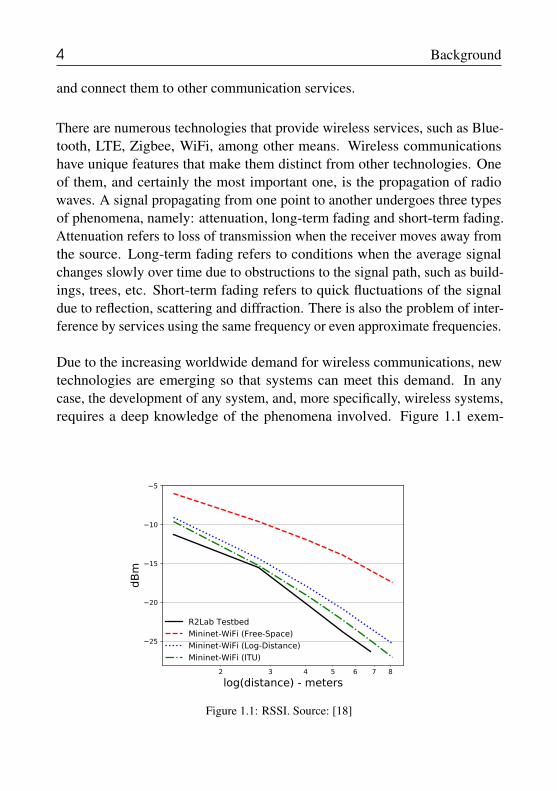
Due to the increasing worldwide demand for wireless communications, newtechnologies are emerging so that systems can meet this demand. In anycase, the development of any system, and, more specifically, wireless systems,requires a deep knowledge of the phenomena involved. Figure 1.1 exem-
� � � � � � �
����������������������
−25
−20
−15
−10
−5
dBm
R2Lab��������
�������������������������
���������������������������
������������������
Figure 1.1: RSSI. Source: [18]
1.2 WiFi: IEEE 802.11-based wireless local area networks 5
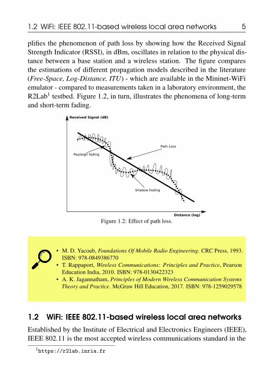
plifies the phenomenon of path loss by showing how the Received SignalStrength Indicator (RSSI), in dBm, oscillates in relation to the physical dis-tance between a base station and a wireless station. The figure comparesthe estimations of different propagation models described in the literature(Free-Space, Log-Distance, ITU) - which are available in the Mininet-WiFiemulator - compared to measurements taken in a laboratory environment, theR2Lab1 testbed. Figure 1.2, in turn, illustrates the phenomena of long-termand short-term fading.
Distance (log)
Received Signal (dB)
Shadow Fading
Path Loss
Rayleigh fading
Figure 1.2: Effect of path loss.
• M. D. Yacoub, Foundations Of Mobile Radio Engineering. CRC Press, 1993.ISBN: 978-0849386770
• T. Rappaport, Wireless Communications: Principles and Practice, PearsonEducation India, 2010. ISBN: 978-0130422323
• A. K. Jagannatham, Principles of Modern Wireless Communication SystemsTheory and Practice. McGraw Hill Education, 2017. ISBN: 978-1259029578
1.2 WiFi: IEEE 802.11-based wireless local area networksEstablished by the Institute of Electrical and Electronics Engineers (IEEE),IEEE 802.11 is the most accepted wireless communications standard in the
1https://r2lab.inria.fr

6 Background
IEEE 802.11
2MbpsDSSS, FHSS
802.11
11MbpsCCK, DSSS
802.11b 802.11a
54MbpsOFDM, 5Ghz
54MbpsOFDM, 2.4Ghz
600Mbps4x4 MIMO,2.4/5Ghz
802.11n
VHT< 6Ghz
VHT60Ghz
802.11ac
802.11ad
802.11p
27Mbps5.9Ghz
TV WhiteSpaces
802.11af
1997 2003 2009 2013
802.11g
Figure 1.3: IEEE 802.11 modes.
world. WiFi technology, as it is most commonly known, is the Wireless Lo-cal Area Network (WLAN) technology based on IEEE 802.11, and it is atrademark of the Wi-Fi Alliance. The reasons for the wide acceptance of thispattern are diverse, but the main justification is cost-performance ratio.
As illustrated in Figure 1.3, there are several 802.11 standards, such as theolder 802.11b, 802.11a, and 802.11g versions, and other versions that maybe considered as newer, such as 802.11n, 802.11ac, 802.11p, and so on. Ingeneral, the standards defined for 802.11 operate on two main frequencies:2.4 GHz or 5 GHz. In the example given by Figure 1.4, it can be seen howthe 802.11b standard defines 13 channels on the 2.4 GHz band at 2.4835 Ghz,allocating 22 MHz for each channel, with a spacing of 5 MHz among them.With this arrangement, only channels 1, 6 and 11 can operate without bandoverlap.
The Bit Error Rate (BER), which is a requirement to be fulfilled in the systemdesign, can be determined by knowing the modulation scheme, the type ofencoding and the signal-to-noise ratio (SNR). It is known that an increase intransmitter power results in a higher SNR and a consequent decrease in BER.Obviously, power cannot be increased indefinitely, due to interference and topower limitations in the transmitter itself.

1.2 WiFi: IEEE 802.11-based wireless local area networks 7
Figure 1.4: IEEE 802.11b channels. Source: adapted from [3] (CC BY 2.0)
Table 1.1: Comparing IEEE 802.11 modes.
Protocol Freq. (GHz) Bandwidth(MHz)
Internal SignalRange
External SignalRange
802.11 2.4 20 20 m / 66 ft 100 m / 330 ft802.11a 3.7/ 5 20 35 m / 115 ft 120 m / 390 ft802.11b 2.4 20 35 m / 115 ft 140 m / 460 ft802.11g 2.4 20 38 m / 125 ft 140 m / 460 ft802.11n 2.4/5 20 - 40 70 m / 230 ft 250 m / 820 ft802.11ac 5 20/40/80/160 35 m / 115 ft n/d802.11ad 60 2,160 60 m / 200 ft 100 m / 300 ft802.11ay 60 8000 60 m / 200 ft 1000 m / 3000 ft
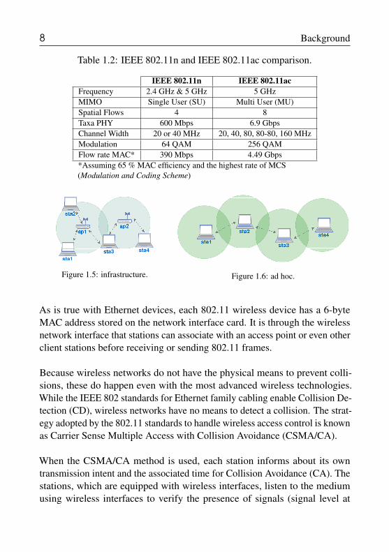
Table 1.1 compares different 802.11 standards in terms of operating frequency,channel bandwidth and coverage radius estimates in indoor and outdoor en-vironments. Table 1.2 compares 802.11n and 802.11ac, two of the newerstandards that incorporate recent advances in wireless communications, suchas spatial flows based on MIMO (Multiple Input Multiple Output).
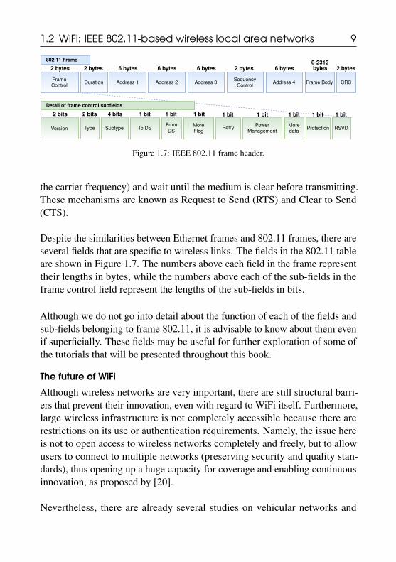
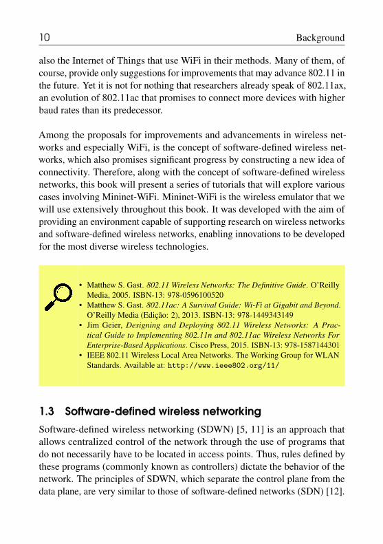
The 802.11 architecture consists primarily of an access point and a numberof wireless stations (clients). In this case, the architecture is defined as BasicService Set (BSS), or infrastructure mode. In contrast, 802.11 networks com-posed of only wireless stations (clients) are referred to as Independent BasicService Set (IBSS) or ad-hoc mode. The graphical representations of thesetwo architectures (or modes of operation) are illustrated in Figures 1.5 e 1.6.
8 Background
Table 1.2: IEEE 802.11n and IEEE 802.11ac comparison.
IEEE 802.11n IEEE 802.11acFrequency 2.4 GHz & 5 GHz 5 GHzMIMO Single User (SU) Multi User (MU)Spatial Flows 4 8Taxa PHY 600 Mbps 6.9 GbpsChannel Width 20 or 40 MHz 20, 40, 80, 80-80, 160 MHzModulation 64 QAM 256 QAMFlow rate MAC* 390 Mbps 4.49 Gbps*Assuming 65 % MAC efficiency and the highest rate of MCS(Modulation and Coding Scheme)
sta1
sta4a3
Figure 1.5: infrastructure. Figure 1.6: ad hoc.
As is true with Ethernet devices, each 802.11 wireless device has a 6-byteMAC address stored on the network interface card. It is through the wirelessnetwork interface that stations can associate with an access point or even otherclient stations before receiving or sending 802.11 frames.
Because wireless networks do not have the physical means to prevent colli-sions, these do happen even with the most advanced wireless technologies.While the IEEE 802 standards for Ethernet family cabling enable Collision De-tection (CD), wireless networks have no means to detect a collision. The strat-egy adopted by the 802.11 standards to handle wireless access control is knownas Carrier Sense Multiple Access with Collision Avoidance (CSMA/CA).
When the CSMA/CA method is used, each station informs about its owntransmission intent and the associated time for Collision Avoidance (CA). Thestations, which are equipped with wireless interfaces, listen to the mediumusing wireless interfaces to verify the presence of signals (signal level at
1.2 WiFi: IEEE 802.11-based wireless local area networks 9
FrameControl
Duration Address 1 Address 2 Address 3Sequency
ControlAddress 4 Frame Body CRC
2 bytes 2 bytes 6 bytes 6 bytes 6 bytes 2 bytes 6 bytes0-2312
2 bytes
Version Type Subtype To DSFrom More
FlagRetry
PowerManagement
Moredata
2 bits 2 bits 4 bits 1 bit
Protection RSVD
1 bit 1 bit 1 bit 1 bit 1 bit 1 bit 1 bit
802.11 Frame
Detail of frame control subfields
DS
bytes
Figure 1.7: IEEE 802.11 frame header.
the carrier frequency) and wait until the medium is clear before transmitting.These mechanisms are known as Request to Send (RTS) and Clear to Send(CTS).
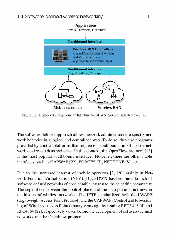
Despite the similarities between Ethernet frames and 802.11 frames, there areseveral fields that are specific to wireless links. The fields in the 802.11 tableare shown in Figure 1.7. The numbers above each field in the frame representtheir lengths in bytes, while the numbers above each of the sub-fields in theframe control field represent the lengths of the sub-fields in bits.
Although we do not go into detail about the function of each of the fields andsub-fields belonging to frame 802.11, it is advisable to know about them evenif superficially. These fields may be useful for further exploration of some ofthe tutorials that will be presented throughout this book.
The future of WiFi
Although wireless networks are very important, there are still structural barri-ers that prevent their innovation, even with regard to WiFi itself. Furthermore,large wireless infrastructure is not completely accessible because there arerestrictions on its use or authentication requirements. Namely, the issue hereis not to open access to wireless networks completely and freely, but to allowusers to connect to multiple networks (preserving security and quality stan-dards), thus opening up a huge capacity for coverage and enabling continuousinnovation, as proposed by [20].
Nevertheless, there are already several studies on vehicular networks and
10 Background
also the Internet of Things that use WiFi in their methods. Many of them, ofcourse, provide only suggestions for improvements that may advance 802.11 inthe future. Yet it is not for nothing that researchers already speak of 802.11ax,an evolution of 802.11ac that promises to connect more devices with higherbaud rates than its predecessor.
Among the proposals for improvements and advancements in wireless net-works and especially WiFi, is the concept of software-defined wireless net-works, which also promises significant progress by constructing a new idea ofconnectivity. Therefore, along with the concept of software-defined wirelessnetworks, this book will present a series of tutorials that will explore variouscases involving Mininet-WiFi. Mininet-WiFi is the wireless emulator that wewill use extensively throughout this book. It was developed with the aim ofproviding an environment capable of supporting research on wireless networksand software-defined wireless networks, enabling innovations to be developedfor the most diverse wireless technologies.
• Matthew S. Gast. 802.11 Wireless Networks: The Definitive Guide. O’ReillyMedia, 2005. ISBN-13: 978-0596100520
• Matthew S. Gast. 802.11ac: A Survival Guide: Wi-Fi at Gigabit and Beyond.O’Reilly Media (Edição: 2), 2013. ISBN-13: 978-1449343149
• Jim Geier, Designing and Deploying 802.11 Wireless Networks: A Prac-tical Guide to Implementing 802.11n and 802.11ac Wireless Networks ForEnterprise-Based Applications. Cisco Press, 2015. ISBN-13: 978-1587144301
• IEEE 802.11 Wireless Local Area Networks. The Working Group for WLANStandards. Available at: http://www.ieee802.org/11/
1.3 Software-defined wireless networking
Software-defined wireless networking (SDWN) [5, 11] is an approach thatallows centralized control of the network through the use of programs thatdo not necessarily have to be located in access points. Thus, rules defined bythese programs (commonly known as controllers) dictate the behavior of thenetwork. The principles of SDWN, which separate the control plane from thedata plane, are very similar to those of software-defined networks (SDN) [12].
1.3 Software-defined wireless networking 11
Control/Management of Wireless and Mobile functions(e.g. mobility, authorization, QoS)
Wireless SDN Controllers
Northbound interface
Southbound interface(e.g. OpenFlow, Capwap)
Applications(Service Providers, Operators)
Wireless RANMobile terminals
Figure 1.8: High-level and generic architecture for SDWN. Source: Adapted from [18]
The software-defined approach allows network administrators to specify net-work behavior in a logical and centralized way. To do so, they use programsprovided by control platforms that implement southbound interfaces on net-work devices such as switches. In this context, the OpenFlow protocol [15]is the most popular southbound interface. However, there are other viableinterfaces, such as CAPWAP [22], FORCES [7], NETCONF [8], etc.
Due to the increased interest of mobile operators [2, 19], mainly in Net-work Function Virtualization (NFV) [10], SDWN has become a branch ofsoftware-defined networks of considerable interest to the scientific community.The separation between the control plane and the data plane is not new inthe history of wireless networks. The IETF standardized both the LWAPP(Lightweight Access Point Protocol) and the CAPWAP (Control and Provision-ing of Wireless Access Points) many years ago by issuing RFC5412 [4] andRFC4564 [22], respectively - even before the development of software-definednetworks and the OpenFlow protocol.
12 Background
Many companies use wireless network management systems by means ofprotocols such as LWAPP and CAPWAP. LWAPP defines message control forconfiguration, authentication and other operations, while CAPWAP is basedon LWAPP and allows a controller to manage different access points.
The number of studies on software-defined wireless networks has grownsignificantly in recent years. It is worth reading [11] for a more comprehen-sive survey, in addition to some software projects, such as: OpenRoads [23],Odin [21], OpenRF [13], Ethanol [17]. Architectures such as CloudMac [6]and Chandelle [16] use CAPWAP in their code. CloudMac describes wirelessnetwork management protocols, such as CAPWAP, as difficult to be config-ured with new features, since access point controllers that use CAPWAP aremostly proprietary systems. Chandelle, on the other hand, proposes a migra-tion between smooth and fast access points using SDN/OpenFlow, but facesintegration issues with regard to traditional switches and CAPWAP.
It is important to mention that there is an open source imple-mentation of the CAPWAP protocol that is compatible withRFC 4515 and RFC 4516, called OpenCAPWAP [1], whosedevelopment started in 2015 (https://github.com/vollero/openCAPWAP).
The benefits of integrating wireless networks with OpenFlow generally involvecentralized management and monitoring, unified policies, greater scheduling,and better control of wireless functions.
Taking into account these benefits and the limitations associated with CAP-WAP, which is likely to be a more robust but closed-source solution, somequestions are unavoidable: “Is CAPWAP compatible with SDWN?”, “Howto improve the OpenFlow specification, so that it supports centralized man-agement of wireless networks? Or even, could you extend it to wirelessnetworks?”, “Are new approaches needed?” or “How much could be recycledfrom the existing infrastructure?”.

1.4 Mininet-WiFi 13
• L. E. Li, Z. M. Mao and J. Rexford, Toward Software-Defined Cellular Net-works. European Workshop on Software Defined Networking (EWSDN),2012.
• A. Gudipati et al., SoftRAN: software defined radio access network. Proceed-ings of Hot topics in software defined networking (HotSDN). 2013.
• C. J. Bernardos et al., An architecture for software defined wireless networking.IEEE Wireless Communications. 2014.
• T. Chen et al., Software defined mobile networks: concept, survey, and researchdirections, IEEE Communications Magazine. 2015.
• Mao Yang et al., Software-Defined and Virtualized Future Mobile and WirelessNetworks: A Survey. Mob. Netw. Appl. 2015.
• I. T. Haque and N. Abu-Ghazaleh, Wireless Software Defined Networking: ASurvey and Taxonomy, in IEEE Communications Surveys & Tutorials. 2016.
• A. Abdelaziz et al. On Software-Defined Wireless Network (SDWN) NetworkVirtualization: Challenges and Open Issues. Computer Journal. 2017.
• Linux Foundation’s Open Networking Foundation (ONF) SDN Wire-less Transport. Available at: https://www.opennetworking.org/tag/wireless-transport/
1.4 Mininet-WiFiNetwork emulation has been widely used in performance evaluation, protocoltesting and debugging, as well as in a variety of research on computer networkarchitectures. A researcher typically has several possible methods to evaluateand validate research data and network protocols, as well as perform analyses,among other operations.
Simulators, emulators and testbeds are the main evaluation tools that helpresearchers in their tasks. Still, regarding their practical applications, all theseevaluation tools are very different in their degree of abstraction. Some of theexperimental platforms that can be used for experimentation with wirelessnetworks are shown in Figure 1.9. In this research field, the emulation ofwireless networks - which has peculiar characteristics, especially comparedwith emulators for wired networks - has to implement node mobility, signalpropagation, among other features, to allow experiments with environmentsthat have interference, signal attenuation, etc.

14 Background
cost = f(CAPEX, time-to-experiment, complexity, resources, etc.)
EmulatorsSimulators TestbedsFormal Math.Models
Live Networks
Experimental OptionsRealism
Increased Realism/Complexity
Mininet-WiFiDCE/ns-3
CoreOpenNet Less real experimental
conditions
Less scalability, flexibility, reproducibility, repeatibility, etc.
OMNeT++Estinet
OpenNet
WARPR2lab
EMULABNitosOrbit
Figure 1.9: Experimental platforms for wireless networks. Source: Adapted from [9].
We will not go into detail about the differences between experimental plat-forms, but we can highlight two important features of Mininet-WiFi: (i) itallows the use of third-party tools without modifications to the source code ofthese tools, and (ii) it uses the actual network protocol stack.
Mininet-WiFi is an emulator for wireless networks that was extended fromMininet, a well-known emulator to researchers working in the field of software-defined networks. Mininet-WiFi has native WiFi support, but other wirelessnetworking technologies can also be simulated in experiments using it. WithMininet-WiFi, the user can virtualize stations and access points and also useexisting Mininet nodes such as hosts, switches and OpenFlow controllers.Consequently, Mininet-WiFi also enables the processing of packages usingthe OpenFlow protocol, an important solution for SDN.
SoftMAC is a term used to describe a type of wireless net-work interface in which the MAC Layer Management Entity(MLME), for example, is expected to be managed using software.Mac80211 is a driver API for SoftMAC.
Mininet-WiFi is developed based on the Mininet code and the most used WiFidriver for Linux systems, SoftMac. With Mininet-WiFi, the user can choose to

1.4 Mininet-WiFi 15
use the old Mininet features independently or use the extensions implementedfor Mininet-WiFi.
1.4.1 ArchitectureThe entire virtualization process of Mininet-WiFi works similarly to Mininet,i.e. it is based on processes that run on Linux network namespaces and virtualnetwork interfaces (see Figure 1.10). Linux network namespaces are, in alogical sense, copies of the Linux operating system’s network stack, whichincludes its own routes, firewall rules and network devices. They act as ifthey were real computers, with the same network properties that a physicalcomputer can have.
root namespace
ofprotocol ofdatapath mn-wifi
controller
eth0
TCP/SSLconnnection
unix sockettmp/s1
tmp/ap1
raw socket
raw socket
pipepipe
h1-eth0 sta1-wlan0
/bin/bash
host/station namespace
h2-eth0 sta2-wlan0
/bin/bash
host/station namespace
switch/access point
if switch:eth if accesspoint:wlan
link
Figure 1.10: Mininet-WiFi architecture. Source: [9]
The behavior of wireless interfaces basically depends on the function theyperform, such as, for instance, the case of stations and access points, whoseinterfaces operate in the managed or master modes, respectively. Just as witha real environment, the stations communicate with access points by a processcalled authentication and association. By default, each station has only onewireless interface, and more can be added if needed. Once connected to anaccess point, stations can communicate with traditional Mininet hosts, if theyare also connected to the access point. Access points, on the other hand, areresponsible for managing stations that are associated with them.
Conceptually, access points are the same entities as the Mininet switches,

16 Background
but equipped with WiFi network cards operating in master mode. Accesspoints are virtualized in the hostapd2 daemon, which basically uses virtualWiFi interfaces to provide access point capabilities. Details on the runningenvironment of Mininet-WiFi are discussed below.
1.4.2 Components
cfg80211
nl80211
Kernel Space
User Space
mac80211_hwsim
station sta1namespace
sta1-wlan0
station sta2namespace
sta2-wlan0
mac80211
root ap1namespace
Mininet-WiFi
ap1-wlan0
Provides MLME management services with which drivers can be developed to support softMAC
Creates Virtual WiFi Interfaces
Configuration managementfor wireless devices
wlan1 wlan2 wlan3
TC tool and
MLMEstation mode
MLMEAP mode
Hostapdiwconfigiwwpa_supplicant
ofdatapath ofprotocol controller
Mo
bili
ty M
od
els
Pro
pag
ati
on
Mo
del
sP
rop
aga
tio
n M
od
els
Configuration managementfor wireless devices
Wmediumd
Figure 1.11: Main components of Mininet-WiFi. Source: [9]
The components comprising the Mininet-WiFi architecture are shown in Fig-ure 1.11. Communication among them occurs as follows: during its initializa-tion, the module called mac80211_hwsim, responsible for the virtualization ofWiFi network cards, is loaded with the number of virtual wireless interfaces re-quired for all nodes previously defined by the user. Located in the kernel spaceof the Linux operating system, all features supported by mac80211_hwsimcome from mac80211, a framework based on SoftMAC that developers use towrite drivers for wireless devices.
Also in the kernel space is cfg80211, which is an 802.11 heap configura-tion API for Linux systems. Its configuration is done by running nl80211,which also performs the interaction between kernel and user spaces.
The main network applications used by Mininet-WiFi are in the user space.Among them is hostapd, whose function is to provide access point services;
2Hostapd (Host Access Point Daemon) is a user-level software capable of launching awireless network interface on access points and authentication servers.

1.4 Mininet-WiFi 17
the TC and Wmediumd programs, which will be described below; iw, iwconfigand wpa_supplicant. The latter is used for, among other tasks, WPA/WPA2authentication.
Interacting with the emulation environmentMininet-WiFi also maintains the same interaction structure as Mininet. E.g.,commands such as those shown below can be used, respectively, for connec-tivity tests or to measure th bandwidth between two nodes. If you are alreadyfamiliar with Mininet, this is certainly nothing new.
mininet-wifi> sta1 ping sta2mininet-wifi> iperf sta1 sta2
In addition to these, other commands exclusive to Mininet-WiFi can be usedfor a better experience with the WiFi environment, such as the ones describedbelow:
mininet-wifi> sta1 iw dev sta1-wlan0 scanmininet-wifi> sta1 iw dev sta1-wlan0 connect ssid-ap1
These commands allow you to scan WiFi networks and connect to one ofthem, respectively. Scripts such as iw, the command used above, are nativelysupported by most Linux operating systems and have not been ported ormodified to work on Mininet-WiFi. Mininet-WiFi can execute any commandand/or program that runs on Linux distributions, such as Ubuntu.
• Ramon dos Reis Fontes, Samira Afzal, Samuel Brito, Mateus Santos, ChristianEsteve Rothenberg. Mininet-WiFi: Emulating Software-Defined WirelessNetworks. In 2nd International Workshop on Management of SDN and NFVSystems 2015. Barcelona, Spain, Nov. 2015. [9]


II2 Beginner . . . . . . . . . . . . . . . . . . . . . . . . . . . . 212.1 Downloading and installing Mininet-WiFi2.2 First steps to use Mininet-WiFi2.3 Customizing topologies2.4 Accessing node information2.5 OVSAP versus UserAP2.6 Graphical User Interface (GUI)2.7 Wireless network emulation2.8 Propagation model2.9 Distance versus received signal2.10 Modifying bitrate2.11 Distance versus throughput2.12 Mobility models
Level: beginner

2. Beginner
In this chapter we introduce Mininet-WiFi and all features supported by thisemulator, highlighting critical information necessary to understand the tutorialsexplored throughout this book. We begin by discussing all steps needed to getMininet-WiFi up and running on your computer.
2.1 Downloading and installing Mininet-WiFi
The Mininet-WiFi source code is a Git repository publicly available on Github.Git is an amazing open source system, capable of handling the distributed ver-sion control of any given project, in this case the Mininet-WiFi project. It wasdevised by Linus Torvalds1 himself as a means of helping the development, atthe time, of a tiny project called Linux.
To ease the searching and following-up of projects managed by Git, developersusually share their Git repository on Github, a platform for creating, managing,further distributing and interacting with open-source projects. This means
1github.com/torvalds
22 Beginner
that the life cycle of a project can be easily analyzed by contributors throughGithub, which keeps any file’s modification history since its origin. In thisbook we only use the basic concepts of the Git system. For more informationabout Git and Github, please refer to <git-scm.com> and <github.com/>.
To obtain Mininet-WiFi’s source code and install it, you will need to per-form a process called cloning, in which all the information pertaining to aproject is downloaded to your computer. Since Mininet-WiFi is a Git reposi-tory on Github, its cloning is carried out using the Git system.
After this brief introduction to Git and Github, you can clone the Mininet-WiFi source code by using the following command line, which consists of theinstruction git clone followed by a link to Mininet-Wifi’s Github repository.
~$ git clone https://github.com/intrig-unicamp/mininet-wifi
Mininet-WiFi relies on Linux Kernel components to functionproperly. Of the different Linux distributions that can be usedto this end, we recommend Ubuntu, since Mininet-WiFi wasextensively tested on it.
In the link to Mininet-WiFi’s repository, intrig-unicamp refers to the profile ororganization where the repository is located on Github. mininet-wifi, in turn,is the name of the repository where the source code is deposited.
If you do not have git, you can install it using the sudo aptinstall git command.
Once the clone is complete, a directory named <mininet-wifi> should be cre-ated. Since the cloning was done from the user’s directory, the Mininet-WiFisource code should be located at </home/your_username/mininet-wifi>, orsimply <∼/mininet-wifi>.
Now you need to install Mininet-WiFi. To do so, you will need to accessthe created directory and execute the sudo util/install.sh command, asfollows.

2.2 First steps to use Mininet-WiFi 23
~$ cd mininet-wifi~/mininet-wifi$ sudo util/install.sh -Wlnfv6
Further information on the Wlnfv6 parameters can be found onthe Mininet-WiFi source code page on Github.
Alternatively, you can also use the virtual machine available on the sourcepage. To ensure that the virtual machine has the latest version of Mininet-WiFi,you must use the commands below.
~/mininet-wifi$ git pull~/mininet-wifi$ sudo make install
Capturing the code through the git clone command ensuresthat the source code will always contain the latest updates imple-mented for Mininet-WiFi.
Even if you already have Mininet-WiFi and/or the virtual machine installed,the git pull command can be issued from the Mininet-WiFi directory atany time. This command will synchronize the code that is on your computerwith the source code available in the Mininet-WiFi source code repository. Bydoing this, you will always have the latest version of Mininet-WiFi installed.
2.2 First steps to use Mininet-WiFiIn the following paragraphs, we will begin to understand how to use Mininet-WiFi.
First, we need to be aware of three commands: sudo mn --version, whichprints the Mininet-WiFi version in use; sudo mn --help, which prints a helpmenu; and sudo mn -c, which is responsible for cleaning up poorly-madeMininet-WiFi executions. Remember this last command, because it will bevery useful later on.
Mininet-WiFi can be started by running a very simple command, sudo mn--wifi. In addition to opening the Command Line Interface (CLI), this com-mand will create a topology consisted of two stations connected to an access

24 Beginner
point via a wireless medium, as well as an SDN controller that is connected tothe access point, as shown in Figure 2.1.
sta2sta1 c0 ap1
Figure 2.1: Simple topology.
~/mininet-wifi$ sudo mn --wifi*** Creating network*** Adding controller*** Adding stations:sta1 sta2*** Adding access points:ap1*** Configuring wifi nodes...*** Adding link(s):(sta1, ap1) (sta2, ap1)*** Configuring nodes*** Starting controller(s)c0*** Starting switches and/or access pointsap1 ...*** Starting CLI:mininet-wifi>
If you already know Mininet, you have probably already used thesudo mn command, which creates a simple topology with twohosts, one switch and one OpenFlow controller, connected by awired medium.
If you notice an error similar to the one below, it means that thereis a controller or process already running on port 6653, the defaultport used by the most recent OpenFlow controllers. This problemcan be solved using the sudo fuser -k 6653/tcp command,which will kill the process that is using port 6653. If the controlleris running on port 6633, the same must be done with this portnumber.
2.2 First steps to use Mininet-WiFi 25
Exception: Please shut down the controller which is running on port 6653:Active Internet connections (servers and established)tcp 0 0 0.0.0.0:6653 0.0.0.0:* LISTEN 2449/ovs-testcontrotcp 0 0 127.0.0.1:55118 127.0.0.1:6653 TIME_WAIT -
To identify the Mininet-WiFi CLI, just search for the text below:
mininet-wifi>
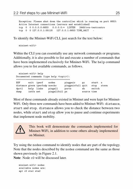
Within the CLI you can essentially use any network commands or programs.Additionally, it is also possible to list and execute a number of commands thathave been implemented exclusively for Mininet-WiFi. The help commandallows you to list available commands, as follows.
mininet-wifi> helpDocumented commands (type help <topic>):========================================EOF exit iperf nodes pingpair py start xdistance gterm iperfudp noecho pingpairfull quit stop xtermdpctl help links pingall ports sh switchdump intfs net pingallfull px source time
Most of these commands already existed in Mininet and were kept for Mininet-WiFi. Only three new commands have been added to Mininet-WiFi: distance,start and stop. distance allows you to check the distance between twonodes, while start and stop allow you to pause and continue experimentsthat implement node mobility.
This book will demonstrate the commands implemented forMininet-WiFi, in addition to some others already implementedon Mininet.
Try using the nodes command to identify nodes that are part of the topology.Note that the nodes described by the nodes command are the same as thoseshown previously in Figure 2.1.Note: Node c0 will be discussed later.
mininet-wifi> nodesavailable nodes are:ap1 c0 sta1 sta2
26 Beginner
As previously mentioned, the sudo mn --wifi command creates a topologywith stations that are connected through a wireless medium to an access point.This can be easily verified using wireless networking tools.
Although the sudo mn --wifi command creates an AP with an SSID called“my-ssid” operating on channel 1 (2412MHz), these values can also be cus-tomized. For instance, we will exit the Mininet-WiFi CLI with the exitcommand and then set up a new SSID and a new channel, as follows:
mininet-wifi> exit~/mininet-wifi$ sudo mn --wifi --ssid=new-ssid --channel=10
Then try the following command.
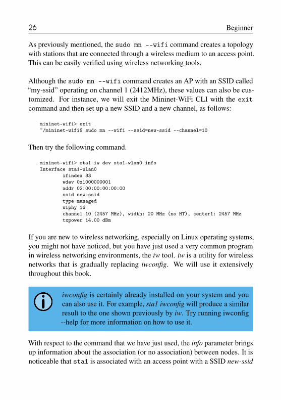
mininet-wifi> sta1 iw dev sta1-wlan0 infoInterface sta1-wlan0
ifindex 33wdev 0x1000000001addr 02:00:00:00:00:00ssid new-ssidtype managedwiphy 16channel 10 (2457 MHz), width: 20 MHz (no HT), center1: 2457 MHztxpower 14.00 dBm
If you are new to wireless networking, especially on Linux operating systems,you might not have noticed, but you have just used a very common programin wireless networking environments, the iw tool. iw is a utility for wirelessnetworks that is gradually replacing iwconfig. We will use it extensivelythroughout this book.
iwconfig is certainly already installed on your system and youcan also use it. For example, sta1 iwconfig will produce a similarresult to the one shown previously by iw. Try running iwconfig--help for more information on how to use it.
With respect to the command that we have just used, the info parameter bringsup information about the association (or no association) between nodes. It isnoticeable that sta1 is associated with an access point with a SSID new-ssid
2.2 First steps to use Mininet-WiFi 27
that also operates on channel 10, exactly as defined by the command.
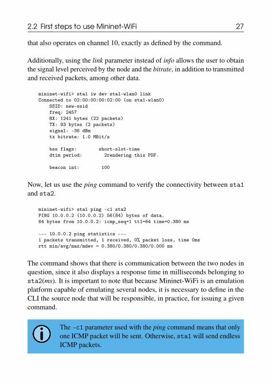
Additionally, using the link parameter instead of info allows the user to obtainthe signal level perceived by the node and the bitrate, in addition to transmittedand received packets, among other data.
mininet-wifi> sta1 iw dev sta1-wlan0 linkConnected to 02:00:00:00:02:00 (on sta1-wlan0)
SSID: new-ssidfreq: 2457RX: 1241 bytes (22 packets)TX: 93 bytes (2 packets)signal: -36 dBmtx bitrate: 1.0 MBit/s
bss flags: short-slot-timedtim period: 2rendering this PDF.
beacon int: 100
Now, let us use the ping command to verify the connectivity between sta1and sta2.
mininet-wifi> sta1 ping -c1 sta2PING 10.0.0.2 (10.0.0.2) 56(84) bytes of data.64 bytes from 10.0.0.2: icmp_seq=1 ttl=64 time=0.380 ms
--- 10.0.0.2 ping statistics ---1 packets transmitted, 1 received, 0% packet loss, time 0msrtt min/avg/max/mdev = 0.380/0.380/0.380/0.000 ms
The command shows that there is communication between the two nodes inquestion, since it also displays a response time in milliseconds belonging tosta2(ms). It is important to note that because Mininet-WiFi is an emulationplatform capable of emulating several nodes, it is necessary to define in theCLI the source node that will be responsible, in practice, for issuing a givencommand.
The -c1 parameter used with the ping command means that onlyone ICMP packet will be sent. Otherwise, sta1 will send endlessICMP packets.

28 Beginner
Thus, as the ping command needs a target node - which can be either a nameor an IP address -, sta2’s destination can also be replaced by its IP address.As can be seen below, the IP address that identifies sta2 is 10.0.0.2/8.
mininet-wifi> sta2 ip addr1: lo: <LOOPBACK,UP,LOWER_UP> mtu 65536 qdisc noqueue state UNKNOWN group
default qlen 1000�→link/loopback 00:00:00:00:00:00 brd 00:00:00:00:00:00inet 127.0.0.1/8 scope host lo
valid_lft forever preferred_lft foreverinet6 ::1/128 scope host
valid_lft forever preferred_lft forever34: sta2-wlan0: <BROADCAST,MULTICAST,UP,LOWER_UP> mtu 1500 qdisc htb state
UP group default qlen 1000�→link/ether 02:00:00:00:01:00 brd ff:ff:ff:ff:ff:ffinet 10.0.0.2/8 scope global sta2-wlan0
valid_lft forever preferred_lft foreverinet6 fe80::ff:fe00:100/64 scope link
valid_lft forever preferred_lft forever
Alternatively, you can also open different terminals for each node and issuecommands as if they were being sent directly to a computer, exactly as it hap-pens in the real world (see Figure 2.2). For example, the following commandwill open two terminals, one for sta1 and another for sta2. Once there is aterminal for each node, it will no longer be necessary to indicate which one isthe origin, as explained in the previous paragraph.
mininet-wifi> xterm sta1 sta2
Xterm may not work as expected if there is no GUI enabled onyour operating system.
Now, we will perform a few routines and exclusive actions of the wirelessenvironment. To begin, we will disconnect sta1 from ap1 and confirm thedisassociation by issuing the following command:
mininet-wifi> sta1 iw dev sta1-wlan0 disconnectmininet-wifi> sta1 iw dev sta1-wlan0 link
Not connected.
So let us try a new ping between sta1 and sta2.

2.2 First steps to use Mininet-WiFi 29
mininet-wifi> sta1 ping -c1 sta2PING 10.0.0.2 (10.0.0.2) 56(84) bytes of data.From 10.0.0.1 icmp_seq=1 Destination Host Unreachable
--- 10.0.0.2 ping statistics ---1 packets transmitted, 0 received, +1 errors, 100% packet loss, time 0ms
As you can see, station sta1 is no longer associated with access point ap1, soit would be logically impossible to perform any kind of communication withsta2.
Now, we will connect sta1 again to the ap1 access point and confirm theassociation.
mininet-wifi> sta1 iw dev sta1-wlan0 connect new-ssidmininet-wifi> sta1 iw dev sta1-wlan0 linkConnected to 02:00:00:00:02:00 (on sta1-wlan0)
SSID: new-ssidfreq: 2457RX: 370 bytes (9 packets)TX: 202 bytes (3 packets)signal: -36 dBmtx bitrate: 6.0 MBit/s
bss flags: short-slot-timedtim period: 2beacon int: 100
Figure 2.2: Executing xterm.
30 Beginner
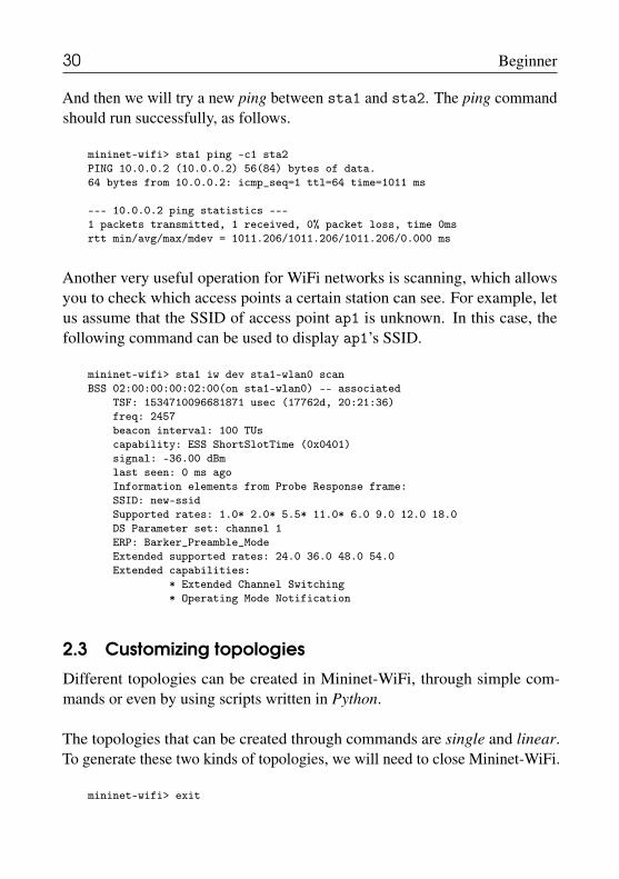
And then we will try a new ping between sta1 and sta2. The ping commandshould run successfully, as follows.
mininet-wifi> sta1 ping -c1 sta2PING 10.0.0.2 (10.0.0.2) 56(84) bytes of data.64 bytes from 10.0.0.2: icmp_seq=1 ttl=64 time=1011 ms
--- 10.0.0.2 ping statistics ---1 packets transmitted, 1 received, 0% packet loss, time 0msrtt min/avg/max/mdev = 1011.206/1011.206/1011.206/0.000 ms
Another very useful operation for WiFi networks is scanning, which allowsyou to check which access points a certain station can see. For example, letus assume that the SSID of access point ap1 is unknown. In this case, thefollowing command can be used to display ap1’s SSID.
mininet-wifi> sta1 iw dev sta1-wlan0 scanBSS 02:00:00:00:02:00(on sta1-wlan0) -- associated
TSF: 1534710096681871 usec (17762d, 20:21:36)freq: 2457beacon interval: 100 TUscapability: ESS ShortSlotTime (0x0401)signal: -36.00 dBmlast seen: 0 ms agoInformation elements from Probe Response frame:SSID: new-ssidSupported rates: 1.0* 2.0* 5.5* 11.0* 6.0 9.0 12.0 18.0DS Parameter set: channel 1ERP: Barker_Preamble_ModeExtended supported rates: 24.0 36.0 48.0 54.0Extended capabilities:
* Extended Channel Switching* Operating Mode Notification
2.3 Customizing topologies
Different topologies can be created in Mininet-WiFi, through simple com-mands or even by using scripts written in Python.
The topologies that can be created through commands are single and linear.To generate these two kinds of topologies, we will need to close Mininet-WiFi.
mininet-wifi> exit
2.3 Customizing topologies 31
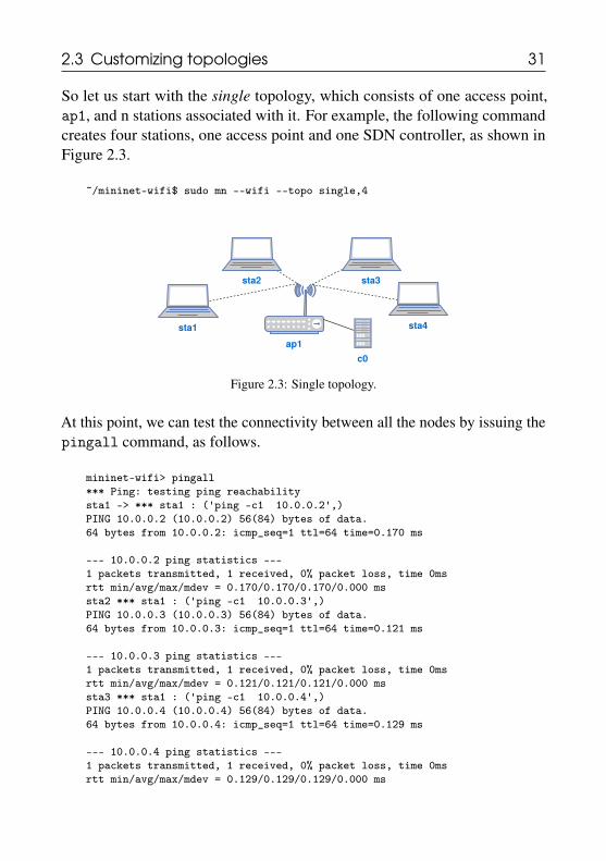
So let us start with the single topology, which consists of one access point,ap1, and n stations associated with it. For example, the following commandcreates four stations, one access point and one SDN controller, as shown inFigure 2.3.
~/mininet-wifi$ sudo mn --wifi --topo single,4
ap1
sta4
sta3sta2
sta1
c0
Figure 2.3: Single topology.
At this point, we can test the connectivity between all the nodes by issuing thepingall command, as follows.
mininet-wifi> pingall*** Ping: testing ping reachabilitysta1 -> *** sta1 : ('ping -c1 10.0.0.2',)PING 10.0.0.2 (10.0.0.2) 56(84) bytes of data.64 bytes from 10.0.0.2: icmp_seq=1 ttl=64 time=0.170 ms
--- 10.0.0.2 ping statistics ---1 packets transmitted, 1 received, 0% packet loss, time 0msrtt min/avg/max/mdev = 0.170/0.170/0.170/0.000 mssta2 *** sta1 : ('ping -c1 10.0.0.3',)PING 10.0.0.3 (10.0.0.3) 56(84) bytes of data.64 bytes from 10.0.0.3: icmp_seq=1 ttl=64 time=0.121 ms
--- 10.0.0.3 ping statistics ---1 packets transmitted, 1 received, 0% packet loss, time 0msrtt min/avg/max/mdev = 0.121/0.121/0.121/0.000 mssta3 *** sta1 : ('ping -c1 10.0.0.4',)PING 10.0.0.4 (10.0.0.4) 56(84) bytes of data.64 bytes from 10.0.0.4: icmp_seq=1 ttl=64 time=0.129 ms
--- 10.0.0.4 ping statistics ---1 packets transmitted, 1 received, 0% packet loss, time 0msrtt min/avg/max/mdev = 0.129/0.129/0.129/0.000 ms

32 Beginner
The other topology that can be created using commands is linear, whichconsists of n access points and n stations, in which each station is associatedwith one access point and all the access points are connected in a linear way.For example, the following command creates four access points, four stations,and one SDN controller, as shown in Figure 2.4.
~/mininet-wifi$ sudo mn --wifi --topo linear,4
ap1 ap2 ap3 ap4
sta4sta3sta2sta1
c0
Figure 2.4: Linear topology.
The customization of topologies, on the other hand, is done by means of scriptsthat contain all the information about the topology as well as the configurationof its nodes. In the </mininet-wifi/examples> directory there is a wide varietyof scripts that can be used as a basis for creating custom topologies.
It is always recommended that you check whether there is a script alreadydeveloped for the scenario you want to work on. This helps you to create yourown. Throughout this book we will use various scripts, which will certainlyhelp in understanding how they can be customized.
2.4 Accessing node informationNow, let us learn how to get information from the nodes that make up atopology. To do so, we will create the simplest topology and add two newparameters: position and wmediumd. The position parameter will define initialpositions for the nodes, while the wmediumd parameter will enable wmediumd,a wireless simulator that will be shown in 2.7.2.
~/mininet-wifi$ sudo mn --wifi --link=wmediumd --position
2.4 Accessing node information 33
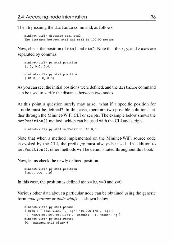
Then try issuing the distance command, as follows:
mininet-wifi> distance sta1 sta2The distance between sta1 and sta2 is 100.00 meters
Now, check the position of sta1 and sta2. Note that the x, y, and z axes areseparated by commas.
mininet-wifi> py sta1.position[1.0, 0.0, 0.0]
mininet-wifi> py sta2.position[101.0, 0.0, 0.0]
As you can see, the initial positions were defined, and the distance commandcan be used to verify the distance between two nodes.
At this point a question surely may arise: what if a specific position fora node must be defined? In this case, there are two possible solutions: ei-ther through the Mininet-WiFi CLI or scripts. The example below shows thesetPosition() method, which can be used with the CLI and scripts.
mininet-wifi> py sta1.setPosition('10,0,0')
Note that when a method implemented on the Mininet-WiFi source codeis evoked by the CLI, the prefix py must always be used. In addition tosetPosition(), other methods will be demonstrated throughout this book.
Now, let us check the newly defined position.
mininet-wifi> py sta1.position[10.0, 0.0, 0.0]
In this case, the position is defined as: x=10, y=0 and z=0.
Various other data about a particular node can be obtained using the genericform node.params or node.wintfs, as shown below.
mininet-wifi> py sta1.params{'wlan': ['sta1-wlan0'], 'ip': '10.0.0.1/8', 'ip6':
'2001:0:0:0:0:0:0:1/64', 'channel': 1, 'mode': 'g'}�→mininet-wifi> py sta1.wintfs{0: <managed sta1-wlan0>}

34 Beginner
Now, you can filter the desired information as follows.
mininet-wifi> py sta1.wintfs[0].freq2.412mininet-wifi> py sta1.wintfs[0].modegmininet-wifi> py sta1.wintfs[0].txpower14mininet-wifi> py sta1.wintfs[0].range62mininet-wifi> py sta1.wintfs[0].antennaGain5
wintfs[0] means that the information to be obtained comes from the firstwireless interface. If the node has multiple interfaces, wintfs[n] - e.g. wintfs[1]to indicate the second interface and so on - can also be used.
2.5 OVSAP versus UserAP
Mininet-WiFi supports two types of access points that differ basically in thelocation where they are run. OVSAP or OVSKernelAP runs in the kernel spaceof the operating system, whereas the UserAP is executed in the user space.Additionally, you may prefer one over the other due to possible advantages,such as supported features and performance.
For example, some features may be supported by one and not by another.Until recently, OVSAP did not support meter tables, a type of table belongingto the OpenFlow protocol that is responsible for Quality of Service (QoS)-related operations, which was included in version 1.3 of this protocol. On theother hand, UserAP already supported it by then.
Another important issue is the possibility of running switches or access pointsin particular network namespaces. In this case, OVS does not support thisfeature natively yet, unlike UserAP, which supports it. What does that mean?Try using the following command.
~/mininet-wifi$ sudo mn --wifi
It allows you to view the interfaces of the ap1 access point.

2.5 OVSAP versus UserAP 35
mininet-wifi> ap1 ip link1: lo: <LOOPBACK,UP,LOWER_UP> mtu 65536 qdisc noqueue state UNKNOWN mode
DEFAULT group default qlen 1000�→link/loopback 00:00:00:00:00:00 brd 00:00:00:00:00:00
2: enp2s0: <NO-CARRIER,BROADCAST,MULTICAST,UP> mtu 1500 qdisc fq_codelstate DOWN mode DEFAULT group default qlen 1000�→link/ether 84:7b:eb:fc:63:1a brd ff:ff:ff:ff:ff:ff
3: wlp1s0: <BROADCAST,MULTICAST,UP,LOWER_UP> mtu 1500 qdisc noqueue stateUP mode DORMANT group default qlen 1000�→link/ether f8:da:0c:95:12:d3 brd ff:ff:ff:ff:ff:ff
4: docker0: <NO-CARRIER,BROADCAST,MULTICAST,UP> mtu 1500 qdisc noqueuestate DOWN mode DEFAULT group default�→link/ether 02:42:04:ed:bc:24 brd ff:ff:ff:ff:ff:ff
5: br-7e51375c6c71: <NO-CARRIER,BROADCAST,MULTICAST,UP> mtu 1500 qdiscnoqueue state DOWN mode DEFAULT group default�→link/ether 02:42:6f:43:07:ee brd ff:ff:ff:ff:ff:ff
6: hwsim0: <BROADCAST,MULTICAST> mtu 1500 qdisc noop state DOWN modeDEFAULT group default qlen 1000�→link/ieee802.11/radiotap 12:00:00:00:00:00 brd ff:ff:ff:ff:ff:ff
9: ap1-wlan1: <BROADCAST,MULTICAST,UP,LOWER_UP> mtu 1500 qdisc tbf masterovs-system state UP mode DEFAULT group default qlen 1000�→link/ether 02:00:00:00:02:00 brd ff:ff:ff:ff:ff:ff
10: ovs-system: <BROADCAST,MULTICAST> mtu 1500 qdisc noop state DOWN modeDEFAULT group default qlen 1000�→link/ether ee:99:70:bb:39:89 brd ff:ff:ff:ff:ff:ff
11: ap1: <BROADCAST,MULTICAST> mtu 1500 qdisc noop state DOWN mode DEFAULTgroup default qlen 1000�→link/ether 0a:94:5d:2c:8b:40 brd ff:ff:ff:ff:ff:ff
Note that a large number of network interfaces can be viewed, including thosethat, in practice, do not integrate the ap1 access point, such as the wireless andwired interfaces of the computer running Mininet-WiFi. This is the behaviorobserved when OVS, the default type of switch or access point for Mininet-WiFi, is being used.
Now, let us look at how UserAP behaves. To do so, run the following com-mand.
~/mininet-wifi$ sudo mn --wifi --ap user --innamespace
The –innamespace parameter was not used with OVS because itdoes not support this command yet. –innamespace is responsiblefor making the node run in its own network namespace, insteadof the root network namespace.

36 Beginner
After that, check the interfaces of the ap1 access point.
mininet-wifi> ap1 ip link1: lo: <LOOPBACK> mtu 65536 qdisc noop state DOWN mode DEFAULT group
default qlen 1000�→link/loopback 00:00:00:00:00:00 brd 00:00:00:00:00:00
2: ap1-eth0@if46: <BROADCAST,MULTICAST,UP,LOWER_UP> mtu 1500 qdisc noqueuestate UP mode DEFAULT group default qlen 1000�→link/ether de:93:af:2c:68:a0 brd ff:ff:ff:ff:ff:ff link-netnsid 0
45: ap1-wlan1: <BROADCAST,MULTICAST,UP,LOWER_UP> mtu 1500 qdisc tbf stateUP mode DEFAULT group default qlen 1000�→link/ether 02:00:00:00:02:00 brd ff:ff:ff:ff:ff:ff
As you can realize, the number of network interfaces has dropped considerably.The loopback interface was expected to appear among the results, in additionto the ap1-wlan1 interface, which is the wireless interface of the ap1 accesspoint. The only interface that could be considered as unexpected would bethe ap1-eth0 interface, which is the interface used to connect to the SDNcontroller.
Another relevant issue between OVSAP and UserAP is the performance.UserAP’s performance has significantly worsened since the releases of thenewer versions of the Linux kernel. The reason? We confess not to have ananswer to this question. However, we invite you to check this issue in practice.
The following command will run Mininet with OVS and test the through-put between nodes h1 and h2.
~/mininet-wifi$ sudo mn --test iperf*** Iperf: testing TCP bandwidth between h1 and h2*** Results: ['40.1 Gbits/sec', '40.0 Gbits/sec']
The following command runs Mininet with UserSwitch and measures thethroughput between the same nodes, h1 and h2.
~/mininet-wifi$ sudo mn --switch=user --test iperf*** Iperf: testing TCP bandwidth between h1 and h2*** Results: ['171 Mbits/sec', '172 Mbits/sec']

2.6 Graphical User Interface (GUI) 37
If you are not able to execute the previous command, you need tostart an SDN controller on another terminal and replace --testiperf by --controller=remote. Then, after starting the con-troller, run iperf on the Mininet-WiFi CLI as follows: iperf h1h2.
You may be wondering: why UserSwitch? UserAP has been extended fromMininet’s UserSwitch. So in practice, they are the same switch or accesspoint. But back to the result, did you notice the difference between them?UserSwitch has much lower performance compared to OVS.
With respect to UserAP still, an example of its implementation is Basic Open-Flow Software Switch (BOFUSS), a successor of ofsoftswitch132. It has beenemployed in several studies and you may definitely want to use it at somepoint. BOFUSS promises to eliminate most performance-related issues.
To install BOFUSS, just run sudo util/install.sh -3f fromMininet-WiFi’s root directory.
2.6 Graphical User Interface (GUI)For those who do not know Python or are new to Mininet-WiFi, currentlythere are two options for creating scripts in Python with the support of graphicinterfaces: by using Visual Network Descriptor (VND) or MiniEdit.
2.6.1 Visual Network Descriptor
Requirement(s): web server, php, flash player, visual networkdescriptor
Visual Network Descriptor, or simply VND, is a tool created for a master’swork that is able to generate Python scripts for Mininet-WiFi via a web browser.Written predominantly in the Flex programming language, VND also includes
2https://github.com/CPqD/ofsoftswitch13

38 Beginner
some instructions in PHP and XML.
Using VND is relatively simple. First you need to make a clone of its sourcecode, which can be downloaded at https://github.com/ramonfontes/vnd, and follow the installation steps available on the source code page. Ingeneral terms, you must have a web server, PHP and Flash Player installed.Then just access it through your preferred web browser. If all goes well, ascreen similar to the one shown in Figure 2.5 should appear.
Figure 2.5: Visual Network Descriptor.
With VND open, you can use the mouse cursor to select the nodes that youwant to include in the topology and their respective connections. You canalso create settings for nodes and save the topology for later use. To generatescripts for Mininet-WiFi, just follow the File->Export->Export to Mininet-WiFi menu. A standard file with a .sh extension will be created; it consists ofPython statements and can be executed as if it were a Python file.
For example, a script named <mytopology.sh> can be executed as follows.
~/mininet-wifi$ sudo python mytopology.sh
Visual Network Descriptor:https://youtu.be/KsoRMnDP_PA

2.6 Graphical User Interface (GUI) 39
2.6.2 MiniEdit
Requirement(s): scripts only
Another alternative for creating topologies with graphics support is MiniEdit.Written in Python, MiniEdit was initially developed for Mininet and has beenconstantly upgraded to work with Mininet-WiFi. The goal of MiniEdit’s de-velopers is to make all the features supported by Mininet-WiFi available onMiniEdit.
MiniEdit has a fairly simple user interface that features a screen with a line oftool icons on the left side of the window and a menu bar at the top. It comesalready included in the Mininet-WiFi source code.
To use it, just run <examples/miniedit.py>.
~/mininet-wifi$ sudo python examples/miniedit.py
Figure 2.6: Miniedit.
After you run it, a screen similar to the one shown in Figure 2.6 should appear.With it you can add nodes supported by Mininet-WiFi and their respectivesettings, in addition to their links, of course. In the current version of MiniEdit,different types of scenarios are already supported, for example: adhoc andmesh networks, WiFi-Direct, Radius protocol, WPA, among other environ-ments.

40 Beginner
You might ask: what is the best alternative to work with GUI? MiniEditor VND? You may want to use MiniEdit, since it is a part of Mininet-WiFi.There is also a tendency for VND to be gradually discontinued.
MiniEdit and Mininet-WiFi:https://youtu.be/j4JS4xxCrCA
2.6.3 Viewing 2D and 3D graphicsViewing topologies by means of graphics is another feature that can be used inMininet-WiFi. You can generate both 2D and 3D graphics. Nevertheless, thereare situations where 3D graphics are very useful, such as surveys involvingdrones and satellites, since the representation of different levels of altitudesmay be necessary.
Thus, given its importance, we will then understand how it is possible togenerate 2D and 3D graphics on Mininet-WiFi. Initially we will learn to createthe two types of graphics (2D and 3D) using the CLI.
The command below will generate a 2D topology.
~/mininet-wifi$ sudo mn --wifi --plot --position
While the following command will generate a 3D topology.
~/mininet-wifi$ sudo mn --wifi --plot3d --position
All scripts available in the </examples> directory - a Mininet-WiFi directorywhere you can find a wide variety of ready-to-run scripts - generate 2D graph-ics. If you choose to generate 3D graphics, simply make a small change in thecode.
For example, let us take as an example <position.py>, available in the </exam-ples> directory. This file contains the following content:

2.6 Graphical User Interface (GUI) 41
net.plotGraph(max_x=100, max_y=100)
As can be seen, only the x and y axes were defined and the resulting graph willbe somewhat similar to the one shown in Figure 2.7. Therefore, to generate3D graphics, simply add the z axis, which will produce something similar towhat was shown in Figure 2.8.
Figure 2.7: 2D Graphic. Figure 2.8: 3D Graphic.
net.plotGraph(max_x=100, max_y=100, max_z=100)
Optionally, minimum values for x, y and z axes can also be defined.
net.plotGraph(min_x=10, min_y=10, min_z=10, max_x=100, max_y=100,max_z=100)�→
Graphics generated by Mininet-WiFi are supported by matplotlib,a data visualization library available in the Python programminglanguage.
Building 3D Graphic:https://youtu.be/lMkIV0YBTss

42 Beginner
2.7 Wireless network emulationWireless media emulation in Mininet-WiFi can be done in two ways: withTC3 or Wmediumd4. Let us then understand how to use them and what arethe differences between them.
2.7.1 TC (Traffic Control)If Mininet-WiFi is running, quit it. Then start it again with the followingcommand:
~/mininet-wifi$ sudo mn --wifi --position
Now, view the TC information on the Mininet-WiFi CLI:
mininet-wifi> ap1 tc qdiscqdisc noqueue 0: dev lo root refcnt 2qdisc pfifo_fast 0: dev enp2s0 root refcnt 2 bands 3priomap 1 2 2 2 1 2 0 0 1 1 1 1 1 1 1 1qdisc noqueue 0: dev wlp1s0 root refcnt 2qdisc noqueue 0: dev docker0 root refcnt 2qdisc tbf 2: dev ap1-wlan1 root refcnt 5 rate 54Mbit burst 14998b lat 1.0msqdisc pfifo 10: dev ap1-wlan1 parent 2:1 limit 1000p
The output that interests us is highlighted below:
qdisc tbf 2: dev ap1-wlan1 root refcnt 5rate 54Mbit burst 14998b lat 1.0ms
In general terms, this output instructs ap1 to limit the bandwidth to up to 54Mbits/s, which represents the maximum value that the IEEE 802.11g standardcan nominally support. With this information it is easier to understand howTC works.
Considering that TC values are applied to stations and also that propaga-tion models are supported by Mininet-WiFi, for a distance d between accesspoint and station, there is always a received signal value, which can vary withthe chosen propagation model. Then, as the node is moving to a new position,a new value for d is calculated and from this we obtain the received signal and
3https://en.wikipedia.org/wiki/Tc_(Linux)4https://github.com/ramonfontes/wmediumd/
2.7 Wireless network emulation 43
the bandwidth value that will be applied by TC to the wireless interface of thenode.
In practice, the value applied by TC to ap1 does not change; instead, thevalues applied to the interfaces of the stations change. Thus, in an infrastruc-ture environment we will always have two reference points for the calculationof d: the station and the access point. Two stations may be associated withthe same access point, and different bandwidth values can be assigned to theirinterfaces: one for sta1 and another for sta2.
Now let us imagine a wireless ad hoc network with three stations. As awireless network, we can say that this network consists of a non-infrastructureenvironment, which means that this topology does not have a central node,i.e. the access point. In this type of network the three stations can associatewith each other, where, for example, sta1 can maintain association withsta2 and sta3. However, they only have one wireless interface, and thus areparticularly difficult to control using TC.
What would be the reference point to calculate d for sta1, sta2 or sta3? Dif-ferently from an infrastructure network, where we have two reference pointsfor the calculation of d - station and access point -, in a non-infrastructurenetwork this does not occur. Thus, wireless adhoc and mesh, require the use ofWmediumd, which implements an ideal wireless medium simulator for thesetypes of networks.
2.7.2 WmediumdThe module responsible for virtualizing WiFi network cards on Mininet-WiFi,mac80211_hwsim, uses the same virtual medium for all its wireless nodes.This means that all nodes are internally within reach of each other and can bediscovered by scanning, as we have done with iw previously. If the wirelessinterfaces need to be isolated from each other, the use of Wmediumd is recom-mended.
Wmediumd had been developed since 20115, but only in 2017 it was inte-
5https://github.com/jlopex/mac80211_hwsim
44 Beginner
grated into Mininet-WiFi thanks to Patrick Große6, the developer responsiblefor creating the first Wmediumd extension for Mininet-WiFi.
Unlike TC, which limits the bandwidth available to the interface, Wmedi-umd relies on a signal table7 and manages the isolation of the interfaces inreal time as data travels across the network.
2.7.3 TC versus Wmediumd in practiceStart Mininet-WiFi with the following command.
~/mininet-wifi$ sudo mn --wifi --topo single,3 --position --plot
This command will create three stations that will associate themselves withaccess point ap1. The --plot parameter will open a topology graph. Moredetails on this parameter will be seen later.
Now, check the signal strength perceived by sta1 in relation to the ap1access point by running the scan command.
mininet-wifi> sta1 iw dev sta1-wlan0 scanBSS 02:00:00:00:03:00(on sta1-wlan0) -- associated
TSF: 1536705774286475 usec (17785d, 22:42:54)freq: 2412beacon interval: 100 TUscapability: ESS ShortSlotTime (0x0401)signal: -36.00 dBmlast seen: 0 ms agoInformation elements from Probe Response frame:SSID: my-ssidSupported rates: 1.0* 2.0* 5.5* 11.0* 6.0 9.0 12.0 18.0DS Parameter set: channel 1ERP: Barker_Preamble_ModeExtended supported rates: 24.0 36.0 48.0 54.0Extended capabilities:
* Extended Channel Switching* Operating Mode Notification
Also check the RSSI using the wintfs option:
6https://github.com/patgrosse7https://github.com/ramonfontes/wmediumd/blob/mininet-wifi/tests/
signal_table_ieee80211ax
2.7 Wireless network emulation 45
mininet-wifi> py sta1.wintfs[0].rssi-66.0
As you can see, there is a difference in the signals received by the iw scanand wintfs options. With iw the received signal was -36 dBm, whereas usingwintfs it was -66 dBm. While TC is in use, it will not be possible to get anyupdated information about the signal strength, or any other data that dependson it, by using network commands, such as iw. Perhaps one of the few usefuldata to verify is whether the station sta1 is in fact associated with the accesspoint ap1.
The iw link command can also be used for this, as follows.
mininet-wifi> sta1 iw dev sta1-wlan0 linkConnected to 02:00:00:00:03:00 (on sta1-wlan0)SSID: my-ssidfreq: 2412RX: 12486 bytes (236 packets)TX: 805 bytes (9 packets)signal: -36 dBmtx bitrate: 18.0 MBit/s
bss flags: short-slot-timedtim period: 2beacon int: 100
Now let us move sta1 and test the received signal again by performing a newscan.
mininet-wifi> py sta1.setPosition('250,250,0')mininet-wifi> sta1 iw dev sta1-wlan0 scanBSS 02:00:00:00:03:00(on sta1-wlan0)
TSF: 1536706071142532 usec (17785d, 22:47:51)freq: 2412beacon interval: 100 TUscapability: ESS ShortSlotTime (0x0401)signal: -36.00 dBmlast seen: 0 ms agoInformation elements from Probe Response frame:SSID: my-ssidSupported rates: 1.0* 2.0* 5.5* 11.0* 6.0 9.0 12.0 18.0DS Parameter set: channel 1ERP: Barker_Preamble_ModeExtended supported rates: 24.0 36.0 48.0 54.0Extended capabilities:
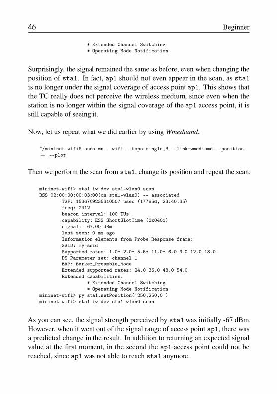
46 Beginner
* Extended Channel Switching* Operating Mode Notification
Surprisingly, the signal remained the same as before, even when changing theposition of sta1. In fact, ap1 should not even appear in the scan, as sta1is no longer under the signal coverage of access point ap1. This shows thatthe TC really does not perceive the wireless medium, since even when thestation is no longer within the signal coverage of the ap1 access point, it isstill capable of seeing it.
Now, let us repeat what we did earlier by using Wmediumd.
~/mininet-wifi$ sudo mn --wifi --topo single,3 --link=wmediumd --position--plot�→
Then we perform the scan from sta1, change its position and repeat the scan.
mininet-wifi> sta1 iw dev sta1-wlan0 scanBSS 02:00:00:00:03:00(on sta1-wlan0) -- associated
TSF: 1536709235310507 usec (17785d, 23:40:35)freq: 2412beacon interval: 100 TUscapability: ESS ShortSlotTime (0x0401)signal: -67.00 dBmlast seen: 0 ms agoInformation elements from Probe Response frame:SSID: my-ssidSupported rates: 1.0* 2.0* 5.5* 11.0* 6.0 9.0 12.0 18.0DS Parameter set: channel 1ERP: Barker_Preamble_ModeExtended supported rates: 24.0 36.0 48.0 54.0Extended capabilities:
* Extended Channel Switching* Operating Mode Notification
mininet-wifi> py sta1.setPosition('250,250,0')mininet-wifi> sta1 iw dev sta1-wlan0 scan
As you can see, the signal strength perceived by sta1 was initially -67 dBm.However, when it went out of the signal range of access point ap1, there wasa predicted change in the result. In addition to returning an expected signalvalue at the first moment, in the second the ap1 access point could not bereached, since ap1 was not able to reach sta1 anymore.

2.8 Propagation model 47
Using wintfs with Wmediumd is not recommended since someimplementations of the latter for the calculation of the receivedsignal were not transferred to Mininet-WiFi. In this case, it isalways preferable to use iw or iwconfig.
2.8 Propagation modelPropagation models are mathematical models typically used by simulators andwireless network emulators to try to mimic the behavior of a wireless medium.In the literature, several propagation models have been proposed in order tosupport the different features of wireless media, such as varied environmenttypes (indoor and outdoor), signal attenuation, interference, etc.
Mininet-WiFi currently supports the following propagation models: FriisPropagation Loss Model, Log-Distance Propagation Loss Model (default),Log-Normal Shadowing Propagation Loss Model, International Telecommuni-cation Union (ITU) Propagation Loss Model and Two-Ray Ground Propaga-tion Loss Model.
The correct choice of propagation model makes a big difference. For ex-ample, one of the variables used in propagation models is the exponent. Theexponent is variable that will instruct the propagation model as to the testingenvironment, i.e. whether it is an indoor or outdoor environment, or whetherit is an interference-free environment or not.
Specifying a propagation model is a simple task. The various Mininet-WiFi sample scripts will certainly support this task, especially <propaga-tionModel.py>. In it you can find the function responsible for defining thepropagation model and its parameters.
To demonstrate how the propagation model can affect the configuration of thenodes that make up the network, we will execute the following script.
~/mininet-wifi$ sudo python examples/propagationModel.py
Using the pre-defined propagation model, we can observe that the signal
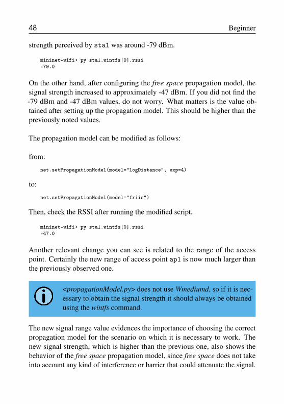
48 Beginner
strength perceived by sta1 was around -79 dBm.
mininet-wifi> py sta1.wintfs[0].rssi-79.0
On the other hand, after configuring the free space propagation model, thesignal strength increased to approximately -47 dBm. If you did not find the-79 dBm and -47 dBm values, do not worry. What matters is the value ob-tained after setting up the propagation model. This should be higher than thepreviously noted values.
The propagation model can be modified as follows:
from:
net.setPropagationModel(model="logDistance", exp=4)
to:
net.setPropagationModel(model="friis")
Then, check the RSSI after running the modified script.
mininet-wifi> py sta1.wintfs[0].rssi-47.0
Another relevant change you can see is related to the range of the accesspoint. Certainly the new range of access point ap1 is now much larger thanthe previously observed one.
<propagationModel.py> does not use Wmediumd, so if it is nec-essary to obtain the signal strength it should always be obtainedusing the wintfs command.
The new signal range value evidences the importance of choosing the correctpropagation model for the scenario on which it is necessary to work. Thenew signal strength, which is higher than the previous one, also shows thebehavior of the free space propagation model, since free space does not takeinto account any kind of interference or barrier that could attenuate the signal.

2.8 Propagation model 49
It is important to note that in addition to the exponent discussed above, thereare other parameters that may be unique or not in relation to each model. Youcan find more information about the supported models and their parameterson Mininet-WiFi’s web page8.
2.8.1 Providing more realismSome propagation models have no signal variation over time. This meansthat if we check the signal strength of a particular node, the perceived signalstrength will always be the same. However, as we all know, the wirelessmedium is not constant and many factors can affect the perceived signalstrength.
Therefore, in cases where the variation in signal strength is important and youneed to represent what happens in the real world with greater fidelity, it isnecessary to set up the fading_coefficient, which produces signal attenuationover time.
To check the effect caused by fading in practice, let us run the followingcode.
~/mininet-wifi$ sudo python examples/wmediumd_interference.py
Now we are able to verify the signal strength variation perceived by a givenstation through iw, as below. Notice that as <wmediumd_interference.py>uses Wmediumd, the signal strength can be obtained by running either iw oriwconfig.
mininet-wifi> sta1 iw dev sta1-wlan0 linkConnected to 02:00:00:00:03:00 (on sta1-wlan0)SSID: new-ssidfreq: 5180RX: 6901 bytes (124 packets)TX: 712 bytes (8 packets)signal: -65 dBmtx bitrate: 12.0 MBit/s
bss flags: short-slot-timedtim period: 2
8http://mininet-wifi.github.io/

50 Beginner
beacon int: 100
mininet-wifi> sta1 iw dev sta1-wlan0 linkConnected to 02:00:00:00:03:00 (on sta1-wlan0)SSID: new-ssidfreq: 5180RX: 8827 bytes (165 packets)TX: 800 bytes (9 packets)signal: -62 dBmtx bitrate: 12.0 MBit/s
bss flags: short-slot-timedtim period: 2beacon int: 100
As you can see, the signal strength perceived by sta1 was initially -65 dBmand then switched to -62 dBm later on. This variation is expected to happenwhenever the received signal level is checked. This is a variation that occursin a random fashion while also respecting the interval defined by the fadingparameter.
Try changing the fading value and check the result. The higherthe fading value, the greater the signal variation.
All propagation models supported by Mininet-WiFi can be foundin <mn_wifi/propagationModels.py>. Should you want to imple-ment new propagation models, you will need to include them inthis file.
2.9 Distance versus received signalIn addition to the throughput, the distance variation will also impact the signalstrength received from the nodes. Obviously, the more distant the source anddestination are, the worse the perceived signal should be. This is due to signalattenuation.
We have already seen in 2.2 how we can visualize the signal strength perceivedby a node. Let us use, then, the same command to observe the perceived signalstrength from different positions. To do so, run <wmediumd_interference.py>.

2.9 Distance versus received signal 51
~/mininet-wifi$ sudo python examples/wmediumd_interference.py
Then check the received signal.
mininet-wifi> sta1 iw dev sta1-wlan0 linkConnected to 02:00:00:00:03:00 (on sta1-wlan0)
SSID: new-ssidfreq: 5180RX: 9142 bytes (184 packets)TX: 88 bytes (2 packets)signal: -64 dBmtx bitrate: 6.0 MBit/s
bss flags: short-slot-timedtim period: 2beacon int: 100
Now, let us use the distance command to view the distance between sta1and ap1.
mininet-wifi> distance sta1 ap1The distance between sta1 and ap1 is 11.18 meters
As you can see, the distance between them is just over 11 meters, and thesignal level perceived by sta1 was -64 dBm. So let us change the position ofsta1 in order to reduce the distance from access point ap1 and check againthe signal strength received by sta1.
mininet-wifi> py sta1.setPosition('40,40,0')mininet-wifi> distance sta1 ap1The distance between sta1 and ap1 is 26.93 metersmininet-wifi> sta1 iw dev sta1-wlan0 linkConnected to 02:00:00:00:03:00 (on sta1-wlan0)
SSID: new-ssidfreq: 5180RX: 176746 bytes (4379 packets)TX: 1668 bytes (19 packets)signal: -79 dBmtx bitrate: 18.0 MBit/s
bss flags: short-slot-timedtim period: 2beacon int: 100
We can see that after changing the position, the distance increased and con-sequently the signal level decreased from -64 dBm to -79 dBm. This may be

52 Beginner
a simple and obvious conclusion; however, the steps we have just taken aidgreatly in the teaching and learning process.
• Ramon dos Reis Fontes, Mohamed Mahfoudi, Walid Dabbous, Thierry Turletti,Christian Esteve Rothenberg. How far can we go? Towards Realistic Software-Defined Wireless Networking Experiments. In The Computer Journal (SpecialIssue on Software Defined Wireless Networks), 2017.
2.10 Modifying bitrateBitrate refers to the rate of data transmission supported for a given moment.Wi-Fi devices are able to adjust their Modulation and Coding Scheme accord-ing to the received signal level. In practice, the more complex the modulationscheme is, the more bits can be transmitted. In contrast, they also becomemore sensitive to interference and noise, and hence require a cleaner channel.
We will use iw to modify bit rates. To do so, consider using <wmedi-umd_interference.py> one more time.
~/mininet-wifi$ sudo python examples/wmediumd_interference.py
Next, let us do some simple tests and note the difference in the bandwidthvalues obtained for different bitrates.
First, run iperf without changing the bitrate values.
mininet-wifi> iperf sta1 sta2*** Iperf: testing TCP bandwidth between sta1 and sta2*** Results: ['14.3 Mbits/sec', '14.4 Mbits/sec']
Then look at the current bitrate. As you can see below, the bitrate value was54 Mbits/s.
mininet-wifi> sta1 iw dev sta1-wlan0 linkConnected to 02:00:00:00:03:00 (on sta1-wlan0)
SSID: new-ssidfreq: 5180RX: 581186 bytes (7475 packets)

2.10 Modifying bitrate 53
TX: 19278284 bytes (12610 packets)signal: -64 dBmtx bitrate: 54.0 MBit/s
bss flags: short-slot-timedtim period: 2beacon int: 100
Now, change the bitrate and re-measure the bandwidth.
mininet-wifi> sta1 iw dev sta1-wlan0 set bitrates legacy-5 6 9mininet-wifi> iperf sta1 sta2*** Iperf: testing TCP bandwidth between sta1 and sta2*** Results: ['5.87 Mbits/sec', '5.93 Mbits/sec']mininet-wifi> sta1 iw dev sta1-wlan0 linkConnected to 02:00:00:00:03:00 (on sta1-wlan0)
SSID: new-ssidfreq: 5180RX: 840551 bytes (12506 packets)TX: 23301226 bytes (15251 packets)signal: -64 dBmtx bitrate: 9.0 MBit/s
bss flags: short-slot-timedtim period: 2beacon int: 100
Note that the bitrate was limited to 9 Mbits/s and the measurement from iperfdropped to less than 6 Mbits/s.
Finally, let us make another bitrate change and measure the bandwidth oncemore.
mininet-wifi> sta1 iw dev sta1-wlan0 set bitrates legacy-5 6mininet-wifi> iperf sta1 sta2*** Iperf: testing TCP bandwidth between sta1 and sta2*** Results: ['4.37 Mbits/sec', '4.44 Mbits/sec']mininet-wifi> sta1 iw dev sta1-wlan0 linkConnected to 02:00:00:00:03:00 (on sta1-wlan0)
SSID: new-ssidfreq: 5180RX: 1044693 bytes (16503 packets)TX: 26353234 bytes (17256 packets)signal: -64 dBmtx bitrate: 6.0 MBit/s
bss flags: short-slot-timedtim period: 2beacon int: 100
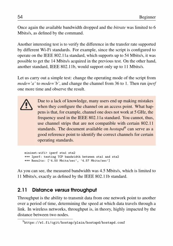
54 Beginner
Once again the available bandwidth dropped and the bitrate was limited to 6Mbits/s, as defined by the command.
Another interesting test is to verify the difference in the transfer rate supportedby different Wi-Fi standards. For example, since the script is configured tooperate on the IEEE 802.11a standard, which supports up to 54 Mbits/s, it waspossible to get the 14 Mbits/s acquired in the previous test. On the other hand,another standard, IEEE 802.11b, would support only up to 11 Mbits/s.
Let us carry out a simple test: change the operating mode of the script frommode=’a’ to mode=’b’, and change the channel from 36 to 1. Then run iperfone more time and observe the result.
Due to a lack of knowledge, many users end up making mistakeswhen they configure the channel on an access point. What hap-pens is that, for example, channel one does not work at 5 GHz, thefrequency used in the IEEE 802.11a standard. You cannot, thus,use channel strips that are not compatible with certain 802.11standards. The document available on hostapd9 can serve as agood reference point to identify the correct channels for certainoperating standards.
mininet-wifi> iperf sta1 sta2*** Iperf: testing TCP bandwidth between sta1 and sta2*** Results: ['4.50 Mbits/sec', '4.57 Mbits/sec']
As you can see, the measured bandwidth was 4.5 Mbits/s, which is limited to11 Mbits/s, exactly as defined by the IEEE 802.11b standard.
2.11 Distance versus throughputThroughput is the ability to transmit data from one network point to anotherover a period of time, determining the speed at which data travels through alink. In wireless networks, throughput is, in theory, highly impacted by thedistance between two nodes.
9https://w1.fi/cgit/hostap/plain/hostapd/hostapd.conf

2.11 Distance versus throughput 55
Among the tools for measuring throughput, iperf is certainly the one thatstands out the most, as it is the preferred tool in most cases. Throughputmeasurement using iperf is relatively simple, since two nodes executing it areenough for it to function, with one of the nodes operating as client and theother as server.
In order to run iperf to verify the relation between distance and bandwidth,we will use the <position.py> file as a basis.
~/mininet-wifi$ sudo python examples/position.py
After running it, you will see a topology with two stations and one access point.
Since the script file has been successfully executed, let us measure the through-put between sta1 and sta2 according to their initial arrangement.
mininet-wifi> iperf sta1 sta2*** Iperf: testing TCP bandwidth between sta1 and sta2*** Results: ['8.42 Mbits/sec', '9.04 Mbits/sec']
Keep a record of the result observed in this test round. The result may sufferslight variations.
Now, we will change the positions of sta1 and sta2 so that they are fur-ther away from access point ap1. Then we will measure the throughputbetween sta1 and sta2 again.
mininet-wifi> py sta1.setPosition('40,90,0')mininet-wifi> py sta2.setPosition('60,10,0')mininet-wifi> iperf sta1 sta2*** Iperf: testing TCP bandwidth between sta1 and sta2*** Results: ['6.98 Mbits/sec', '7.14 Mbits/sec']
Comparing this new result with the previous one, it is clear that the moredistant the stations are from the access point, the smaller the throughput tendsto be.
In Mininet-WiFi, the iperf sta1 sta2 command automati-cally defines sta1 as a server and sta2 as a client. Later onwe will see examples of the most common way of using iperf.

56 Beginner
Publications that have already used Mininet-WiFi for performance re-search:
• Gilani S.M.M., Heang H.M., Hong T., Zhao G., Xu C. OpenFlow-BasedLoad Balancing in WLAN: Throughput Analysis. Communications, SignalProcessing, and Systems (CSPS), 2016.
• Krishna Vijay Singh, Sakshi Gupta, Saurabh Verma, Mayank Pandey. Im-proving performance of TCP for wireless network using SDN. Proceedings ofICDCN, 2019.
2.12 Mobility models
Mobility models are also very important because they try to mimic the mobilityof persons, vehicles or any other object that is mobile, i.e. able to move fromone point to another. There are several studies that try to identify the patternsof human mobility during natural disasters, such as major storms, floods, etc.
As for the propagation models, there are several mobility models that areaccepted by the scientific community worldwide, and some of them are sup-ported by Mininet-WiFi, such as Random Direction, Random Walk, GaussMarkov, among other models. Mobility can be observed either using CLI or agraph, as illustrated in Figure 2.9.
Because of their importance, we will now check how mobility models canbe configured on Mininet-WiFi. To do so, let us use the <mobilityModel.py>script, which contains the Random Direction mobility model in its code. It isimportant to note that for each mobility model there may be unique parameterssuch as minimum and maximum speed limits, areas where nodes can move,etc. All the information you need about mobility model settings can be foundon Mininet-WiFi’s web page10.
Seed is one of the most important mobility model settings. It modifies mobilitysignificantly. For instance, if a seed number one causes the nodes to movefrom certain x and y values, a seed number two will change the initial valuesof x and y. It will not be able to change the mobility behavior, but it may
10http://mininet-wifi.github.io/

2.12 Mobility models 57
Figure 2.9: Working with mobility.
change its own initial positions. This is an important feature because the initialarrangement of the nodes may not always meet the requirements defined for aparticular experiment.
Now that we know a little more about the theory of mobility models, letus run the following script and observe how the nodes behave when configuredwith the Random Direction mobility model.
~/mininet-wifi$ sudo python examples/mobilityModel.py
Record the behavior of the nodes and try to change the mobilitymodel at a later time for comparison purposes.
Then we will test two of the three implemented Mininet-WiFi commands thatwere presented in the 2.2 section: stop and start.
Let us first try the stop command.
mininet-wifi> stop
Should everything go as expected, the stop command will cease mobility,causing the nodes to stop moving. This feature is useful in cases where the
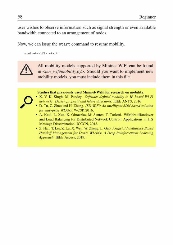
58 Beginner
user wishes to observe information such as signal strength or even availablebandwidth connected to an arrangement of nodes.
Now, we can issue the start command to resume mobility.
mininet-wifi> start
All mobility models supported by Mininet-WiFi can be foundin <mn_wifi/mobility.py>. Should you want to implement newmobility models, you must include them in this file.
Studies that previously used Mininet-WiFi for research on mobility:• K. V. K. Singh, M. Pandey. Software-defined mobility in IP based Wi-Fi
networks: Design proposal and future directions. IEEE ANTS, 2016• D. Tu, Z. Zhao and H. Zhang. ISD-WiFi: An intelligent SDN based solution
for enterprise WLANs. WCSP, 2016,• A. Kaul, L. Xue, K. Obraczka, M. Santos, T. Turletti. WiMobtitHandover
and Load Balancing for Distributed Network Control: Applications in ITSMessage Dissemination. ICCCN, 2018.
• Z. Han, T. Lei, Z. Lu, X. Wen, W. Zheng, L. Guo. Artificial Intelligence BasedHandoff Management for Dense WLANs: A Deep Reinforcement LearningApproach. IEEE Access, 2019.

FAQ

197
Frequently Asked QuestionsI have completed all tutorials. What would be the next step(s)?The answer to this question depends on your goals. But in general, if the goalcomes from the need to develop further scientific research and/or find out inwhich other fields of application Mininet-WiFi has been used, the citationcatalogue is certainly a great reference point. It is continually updated and isavailable on the Mininet-WiFi source code page.
Nevertheless, we find it useful to provide you with a couple of lists of worksthat previously used Mininet-WiFi for research on topics such as video stream-ing, 5G, power management, and other technologies. They are displayedbelow.
Studies that previously used Mininet-WiFi for research on video streaming:• Charles H.F. Santos, Felipe S. Dantas Silva and Augusto J. Venâncio Neto. An
Innovative Dynamic Bit Rate Streaming Approach to Improve Mobile UserMultimedia Quality of Experience. MobiWac, 2017
• Iulisloi Zacarias, Janaína Schwarzrock, Luciano Paschoal Gaspary, Kohl An-derson, Ricardo Q. A. Fernandes, Jorgito M. Stocchero, and Edison Pignatonde Freitas. Enhancing Mobile Military Surveillance based on Video Streamingby Employing Software Defined Networks. Wireless Communications andMobile Computing, 2018.
• Daerawi, Kalamullah Ramli, Kalvein Rantelobo. Performance Evaluation ofScalable High Efficiency Video Coding (SHVC) Transmission. InternationalConference on Science and Technology (ICST), 2018.
• Reviakin, Aleksandr; Zahran, Ahmed H.; Sreenan, Cormac J. dashc: a highlyscalable client emulator for DASH video. MMSys, 2018.
• Yueming Zheng, Ying Wang, Mingda Rui, Andrei Palade, Shane Sheehan andEamonn O Nuallain. Performance Evaluation of HTTP/2 over TLS+TCP andHTTP/2 over QUIC in a Mobile Network. Journal of Information Sciences andComputing Technologies, 2018.

198 FAQ
Studies that previously used Mininet-WiFi for research on 5G, power manage-ment, among other topics.
• Wang, Zeng, and Jinhe Zhou. Power control mechanism in software definedwireless networking. ICCSN. IEEE, 2016.
• Zhang, Xiao, Haijun Wang, and Haitao Zhao. An SDN framework for UAVbackbone network towards knowledge centric networking. IEEE INFOCOM,2018.
• Zacarias, Iulisloi, et al. Combining software-defined and delay-tolerant ap-proaches in last-mile tactical edge networking. IEEE Communications Maga-zine, 2017.
• Mastorakis, Spyridon, Alexander Afanasyev, and Lixia Zhang. On the evolu-tion of ndnSIM: An open-source simulator for NDN experimentation. ACMSIGCOMM Computer Communication Review, 2017.
• Canonico, Roberto, et al. A framework to evaluate 5G networks for smartand fail-safe communications in ERTMS/ETCS. International Conference onReliability, Safety and Security of Railway Systems. Springer, 2017.
• Santos, I., et al. Emulating a Software Defined LTE Radio Access NetworkTowards 5G. International Conference on Communications (COMM). IEEE,2018.
I do not have mac80211_hwsim installed on my computer. How can Iget it?Installing linux-image-extra will most likely install and compile mac80211_hwsimas well.
$ sudo apt-get install linux-image-extra-`uname -r`
I am trying to start Mininet-WiFi, but I am having errors. How can I solvethem?Most of the Mininet-WiFi runtime errors come from past executions that werenot successfully completed. Therefore, it is often necessary to run the sudomn -c command to clear any execution errors not properly completed.
How can I uninstall Mininet-WiFi?To uninstall Mininet-WiFi, simply run the following command.
$ sudo rm -rf /usr/local/bin/mn /usr/local/bin/mnexec/usr/local/lib/python*/*/*mininet* /usr/local/bin/ovs-*/usr/local/sbin/ovs-*
�→�→
199
I would like to know more about Mininet-WiFi. What do I need to do?The Mininet-WiFi Handbook was created for both users and developers. Thisis undoubtedly the best document for information and troubleshooting aboutMininet-WiFi. The mailing list ([email protected]) isalso another important source to consult. It is frequently used by users whoneed new features or find Mininet-WiFi difficult in some situations.
• Web page:http://mininet-wifi.github.io/
• Mailing list mininet-wifi-discuss:https://groups.google.com/forum/#!forum/mininet-wifi-discuss


References

References
[Ago+16] Elena Agostini et al. “OpenCAPWAP v2.0: the new open-source im-plementation of the CAPWAP protocol”. In: International Journalof Network Management 26.6 (Sept. 2016), pages 537–552 (cited onpage 12).
[Ber+14] Carlos Bernardos et al. “An architecture for software defined wirelessnetworking”. In: Wireless Communications, IEEE 21.3 (June 2014),pages 52–61. ISSN: 1536-1284 (cited on page 11).
[Bin+12] Md Asri Bin Ngadi et al. “A taxonomy of cross layer routing met-rics for wireless mesh networks”. In: EURASIP Journal on WirelessCommunications and Networking 2012.1 (May 2012), page 177. ISSN:1687-1499 (cited on page 7).
[Cal15] Pat R. Calhoun. “Lightweight Access Point Protocol”. In: Request forComments 5412. RFC Editor, Nov. 2015 (cited on page 11).
[Cos+12] Salvatore Costanzo et al. “Software Defined Wireless Networks: Un-bridling SDNs”. In: Software Defined Networking (EWSDN), 2012European Workshop on. IEEE, Oct. 2012, pages 1–6. ISBN: 978-1-4673-4554-5 (cited on page 10).

204 References
[Del+12] Peter Dely et al. “CloudMAC - An OpenFlow based architecture for802.11 MAC layer processing in the cloud”. In: Globecom Workshops(GC Wkshps), 2012 IEEE. IEEE, Dec. 2012, pages 186–191. ISBN:978-1-4673-4942-0 (cited on page 12).
[Dor+15] Avri Doria et al. “Forwarding and Control Element Separation (ForCES)Protocol Specification”. In: Request for Comments 5810. RFC Editor,Oct. 2015 (cited on page 11).
[Enn+15] Rob Enns et al. “Network Configuration Protocol (NETCONF)”. In:Request for Comments 6241. RFC Editor, Oct. 2015 (cited on page 11).
[Fon+15] R. R. Fontes et al. “Mininet-WiFi: Emulating software-defined wirelessnetworks”. In: Network and Service Management (CNSM), 2015 11thInternational Conference on. Nov. 2015, pages 384–389 (cited onpages 14–17).
[Han+15] Bo Han et al. “Network function virtualization: Challenges and oppor-tunities for innovations”. In: Communications Magazine, IEEE 53.2(Feb. 2015), pages 90–97 (cited on page 11).
[JK+14] Nachikethas A. Jagadeesan, Bhaskar Krishnamachari, et al. “Software-Defined Networking Paradigms in Wireless Networks: A Survey”. In:ACM Comput. Surv. 47.2 (Nov. 2014), 27:1–27:11. ISSN: 0360-0300(cited on pages 10, 12).
[Kre+15] D. Kreutz et al. “Software-Defined Networking: A ComprehensiveSurvey”. In: Proceedings of the IEEE 103.1 (Jan. 2015), pages 14–76.ISSN: 0018-9219 (cited on pages 10, 88).
[Kum+13] Swarun Kumar et al. “Bringing Cross-layer MIMO to Today’s WirelessLANs”. In: Proceedings of the ACM SIGCOMM 2013 Conference onSIGCOMM. SIGCOMM ’13. Hong Kong, China: ACM, Oct. 2013,pages 387–398. ISBN: 978-1-4503-2056-6 (cited on page 12).
[LHM10] Bob Lantz, Brandon Heller, and Nick McKeown. “A network in alaptop: rapid prototyping for software-defined networks”. In: Proceed-ings of the 9th ACM SIGCOMM Workshop on Hot Topics in Networks.ACM. 2010, page 19 (cited on page ).
[McK+08] Nick McKeown et al. “OpenFlow: Enabling Innovation in CampusNetworks”. In: SIGCOMM Comput. Commun. Rev. 38.2 (Mar. 2008),pages 69–74. ISSN: 0146-4833 (cited on page 11).
[MSS14] Sergey Monin, Alexander Shalimov, and Ruslan Smeliansky. “Chan-delle: Smooth and Fast WiFi Roaming with SDN OpenFlow”. In: 2014(cited on page 12).
205
[Mou+15] Henrique Moura et al. “Ethanol: Software defined networking for802.11 Wireless Networks”. In: IFIP/IEEE International Symposiumon Integrated Network Management, IM 2015, Ottawa, ON, Canada,11-15 May, 2015. IEEE, May 2015, pages 388–396 (cited on page 12).
[Rei+17] Ramon dos Reis Fontes et al. “How Far Can We Go? Towards RealisticSoftware-Defined Wireless Networking Experiments”. In: Comput. J.60.10 (2017), pages 1458–1471 (cited on pages 4, 11).
[Sam+15] Malla Reddy Sama et al. “Software-defined control of the virtualizedmobile packet core”. In: IEEE Communications Magazine 53.2 (2015),pages 107–115 (cited on page 11).
[San+14] M. A. Santos et al. “Software-defined networking based capacity shar-ing in hybrid networks”. In: 2013 21st IEEE International Conferenceon Network Protocols (ICNP). Volume 00. Oct. 2014, pages 1–6 (citedon page 9).
[Sur+12] Lalith Suresh et al. “Towards Programmable Enterprise WLANS withOdin”. In: Proceedings of the First Workshop on Hot Topics in SoftwareDefined Networks. HotSDN ’12. Helsinki, Finland: ACM, Aug. 2012,pages 115–120. ISBN: 978-1-4503-1477-0 (cited on page 12).
[YGC15] Lily Yang, Saravanan Govindan, and Hong Cheng. “Objectives forControl and Provisioning of Wireless Access Points (CAPWAP)”. In:Request for Comments 4564. RFC Editor, Oct. 2015 (cited on page 11).
[Yap+10] Kok-Kiong Yap et al. “Blueprint for Introducing Innovation into Wire-less Mobile Networks”. In: Proceedings of the Second ACM SIG-COMM Workshop on Virtualized Infrastructure Systems and Architec-tures. VISA ’10. New Delhi, India: ACM, Sept. 2010, pages 25–32.ISBN: 978-1-4503-0199-2 (cited on page 12).
