wireless networking radio frequency fundamentals and rf math module-02 jerry bernardini community...
Post on 19-Dec-2015
224 views
TRANSCRIPT

Wireless Networking
Radio Frequency Fundamentals and RF Math
Module-02Jerry Bernardini
Community College of Rhode Island
04/18/23 Wireless Networking J. Bernardini 1

Presentation Reference Material• The California Regional Consortium for
Engineering Advances in Technological Education (CREATE) project
• CWNA Certified Wireless Network Administration Official Study Guide
(PWO-104), David Coleman, David Westcott, 2009, Chapter-1
04/18/23 Wireless Networking J. Bernardini 2

Radio and the Electromagnetic Spectrum
• Radio frequencies are part of the electromagnetic spectrum
04/18/23 Wireless Networking J. Bernardini 3
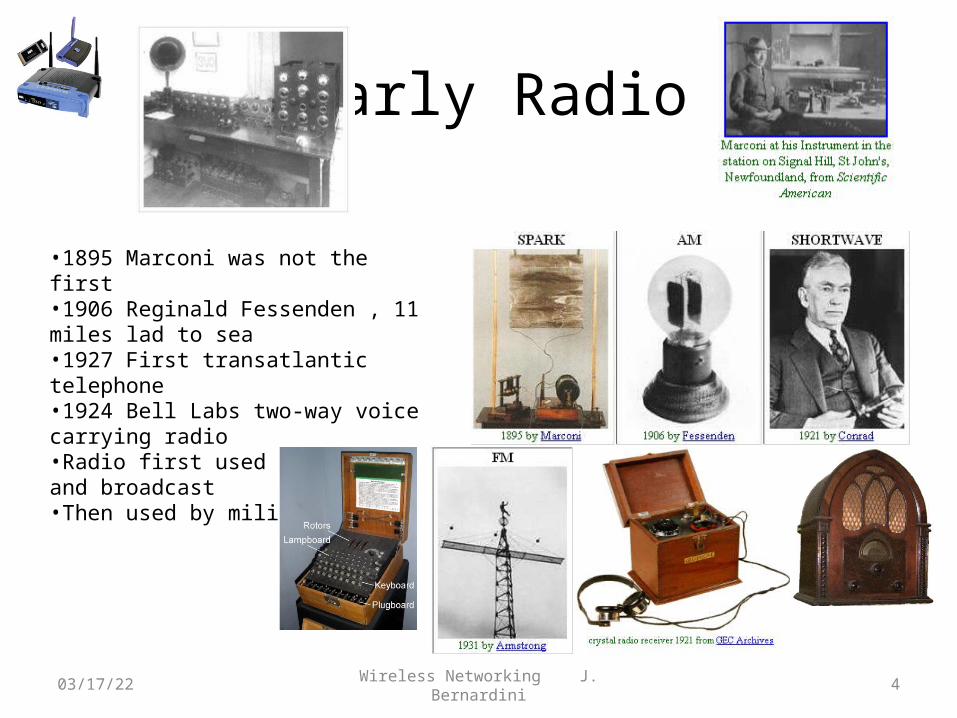
Early Radio
04/18/23 Wireless Networking J. Bernardini 4
•1895 Marconi was not the first•1906 Reginald Fessenden , 11 miles lad to sea•1927 First transatlantic telephone•1924 Bell Labs two-way voice carrying radio•Radio first used for voice and broadcast•Then used by military

Radio Frequency
• Radio frequency, (RF) is a term that refers to alternating current, (AC) having characteristics such that, if the current is input to an antenna, an electromagnetic (EM) field/wave is generated suitable for wireless communications.
AC Signal
Transmission Line Antennaand
Tower
EM Wave

EM Waves
04/18/23 Wireless Networking J. Bernardini 6
•Electromagnetic waves are made up of electric wave and magnetic waves at right angles
•The wave moves at right angle to the electric and magnetic waves
•In a vacuum the wave moves at the speed of light (3x10⁸ meter/sec)
•Electric field is the force on an electric charge
•A moving electric field will produce a moving magnetic field, which produces a moving electric field, ad infinitum
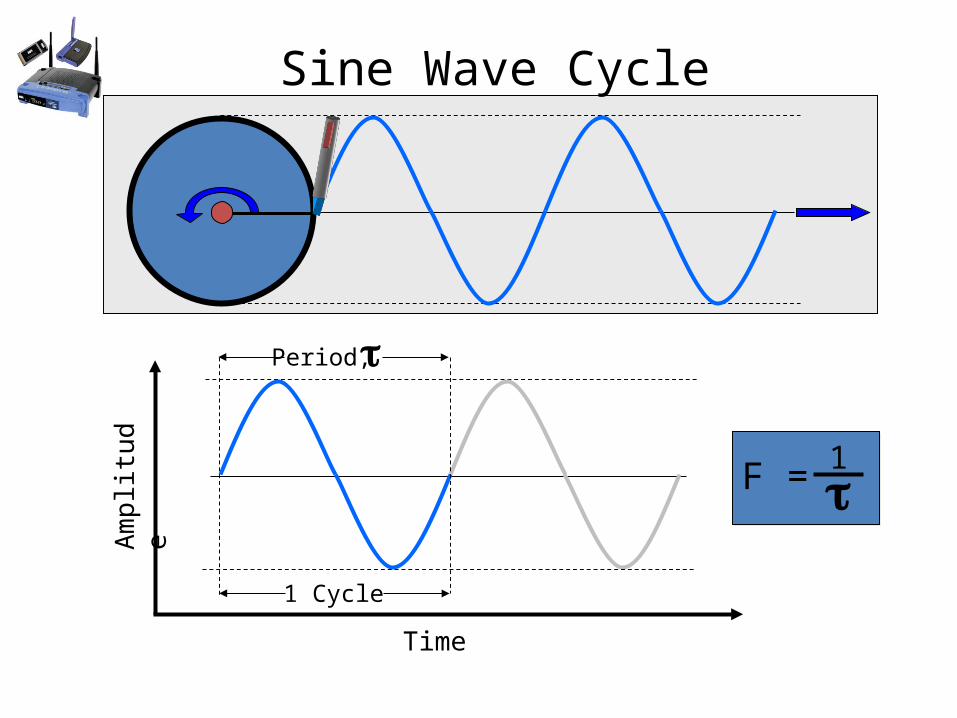
Sine Wave CycleA
mp
litu
de
Time
1 Cycle
Period,
F = 1

RF Properties
• Amplitude - The amount of a signal. Amplitude is measured by determining the amount of fluctuation in air pressure for sound or the voltage of an electrical signal.
Amplitude
Time
Waveform A
Waveform B

RF Properties
• Frequency -The number of repetitions per unit time of a complete waveform, measured in Hertz. The number of complete oscillations per second of electromagnetic radiation.
Amplitude
Time
= Period
F = 1/
A
B

RF Properties
• Wavelength, -The distance that a wave travels in the time it takes to go through one full 360 degree phase change, or one cycle.
Amplitude
Distance

Wavelength
1 Wavelength,
= 300,000,000 m/sFrequency (Hz)
= 984,000,000 f/sFrequency (Hz)
In a Vacuum
= 300,000,000 m/s2.45 GHz
= 0.122 m = 12.2 cm
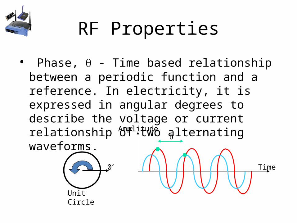
RF Properties
• Phase, - Time based relationship between a periodic function and a reference. In electricity, it is expressed in angular degrees to describe the voltage or current relationship of two alternating waveforms.
Amplitude
Time0
Unit Circle

RF Properties• Polarization – By convention the orientation of
the electric field, (E) with respect to the earth’s surface. Vertical, Horizontal, and Circular/Elliptical polarization.
P
HE
E
EE
A B C D
E

RF Properties• Polarization – By convention the orientation of
the electric field, (E) with respect to the earth’s surface. Vertical, Horizontal, and Circular/Elliptical polarization.
A B C
Earth/Ground Reference
D E
Ceiling

RF Spectrum
Designation Abbreviation Frequencies
Ultra High Frequency
UHF 300 MHz - 3 GHz
Super High Frequency
SHF3 GHz - 30 GHz
Very Low Frequency -
Extremely High Frequency
VLF - EHF 9 kHz – 300 GHz

US Frequency Allocation Chart
• National Telecommunications and Information Administration. http://www.ntia.doc.gov/osmhome/allochrt.html
9 kHz 300 GHz
802.11a, b, g
AMRadio
FMRadio
535-1605kHz
88-108MHz

Amplification and Attenuation
• Amplification/Gain - An increase in signal level, amplitude or magnitude of a signal. A device that does this is called an amplifier.
• Attenuation/Loss - A decrease in signal level, amplitude, or magnitude of a signal. A device that does this is called an attenuator.

Amplification / Gain
100 mW
RF Amplifier
1 W
SignalSource
AntennaINPUT
OUTPUT
The power gain of the RF amplifier is a power ratio.
Power Gain = = = 10 no unitsPower Output
Power Input
1 W
100 mW

Attenuation / Loss
100 mW
RF Attenuator
50 mW
SignalSource
AntennaINPUT
OUTPUT
The power loss of the RF attenuator is a power ratio.
Power Loss = = = 0.5 no unitsPower Output
Power Input
50 mW
100 mW

Attenuation of an EM wave• Attenuation/Loss - A decrease in signal level,
amplitude, or magnitude of a signal.

Parameters & Units of Measure
• Power - The rate at which work is done, expressed as the amount of work per unit time.
• Watt - An International System unit of power equal to one joule per second. The power dissipated by a current of 1 ampere flowing between 1 volt of differential.
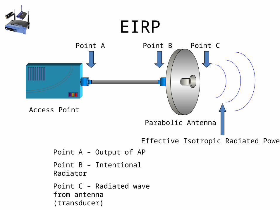
EIRP
Access Point
Point A Point B
Parabolic Antenna
Point C
Point A – Output of AP
Point B – Intentional Radiator
Point C – Radiated wave from antenna (transducer)
Effective Isotropic Radiated Power

Voltage Standing Wave Ratio
• VSWR - is a measure of how well the components of the RF system are matched in impedance. VSWR is the ratio of the maximum voltage to the minimum voltage in a standing wave. For maximum power transfer the ideal VSWR is 1.

Voltage Standing Wave Ratio50
50
50
Output impedance of AP is 50 Impedance of cable is 50 Input impedance of antenna is 50
The impedances are matched so the VSWR = 1

Basic Properties of EM waves• Reflection – cast off or turn back, (bouncing).
Basic Properties of EM waves
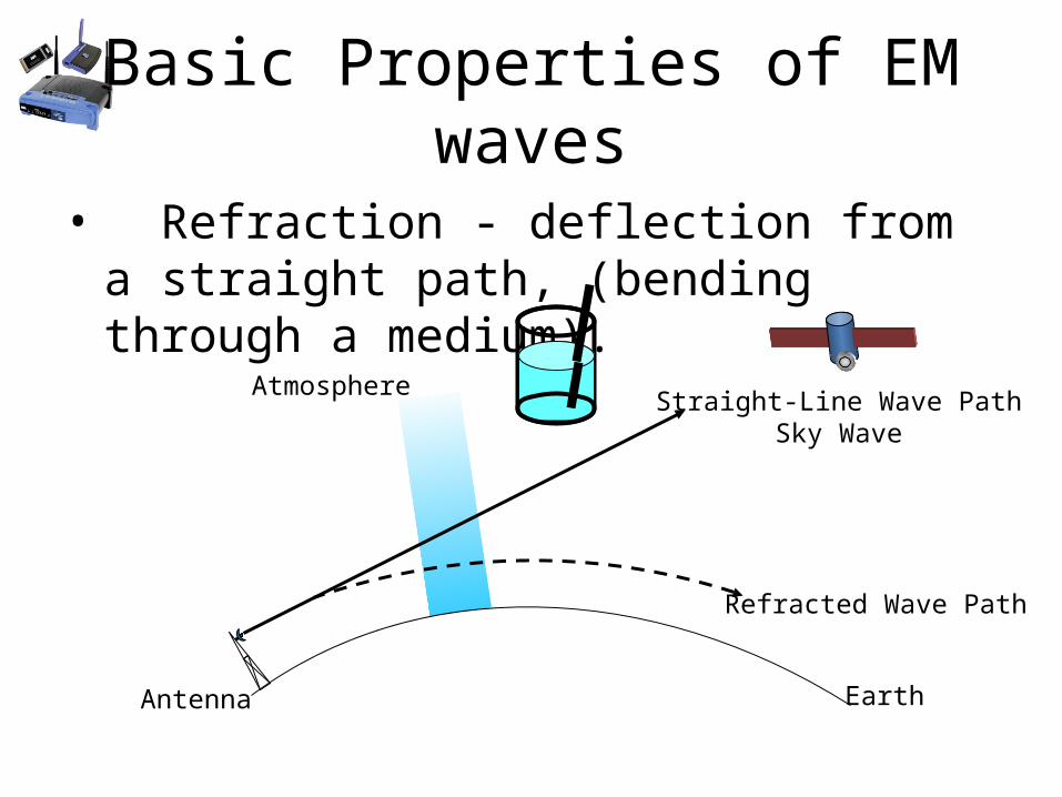
• Refraction - deflection from a straight path, (bending through a medium).
Earth
Atmosphere
Refracted Wave Path
Straight-Line Wave PathSky Wave
Antenna

Basic Properties of EM waves• Diffraction – Change in the directions and
intensities of a group of waves when they pass near the edge of an EM opaque object, (bending around object).
Transmitter Receiver
Bui
ldin
g
ShadowZone
Diffracted Signal

Basic Properties of EM waves• Interference - hinders, obstructs, or impedes.
When two or more wave fronts meet, (colliding).
Direct WaveMultipathInterferenceReflected Wave

Basic Properties of EM waves• Scattering – A specification of the angular
distribution of the electromagnetic energy scattered by a particle or a scattering medium, (dispersion).
Incident Wave

Basic Properties of EM waves• Absorption – The process in which incident
radiant energy is retained by a substance by conversion to some other form of energy.
Incident WaveDrywall
Concrete

Parameters & Units of Measure
• Voltage - electric potential or potential difference expressed in volts.
• Volt - a unit of potential equal to the potential difference between two points on a conductor carrying a current of 1 ampere when the power dissipated between the two points is 1 watt.
A BC

Parameters & Units of Measure
• Current - a flow of electric charge (electrons); The amount of electric charge flowing past a specified circuit point per unit time.
• Ampere – Unit of current.

Parameters & Units of Measure
• Power - The rate at which work is done, expressed as the amount of work per unit time.
• Watt - An International System unit of power equal to one joule per second. The power dissipated by a current of 1 ampere flowing between 1 volt of differential.
P = I x EP = 2A x 5V = 10W

Metric SI Prefixes
• SI prefixes combine with any unit name to give subdivisions and multiples.
Prefix Symbol Magnitude Multiply by
femto- f 10-15 0.000 000 000 000 001
micro- (mu) 10-6 0.000 001
milli- m 10-3 0.001
kilo- k 10+3 1000
Mega M 10+6 1 000 000
Giga G 10+9 1 000 000 000
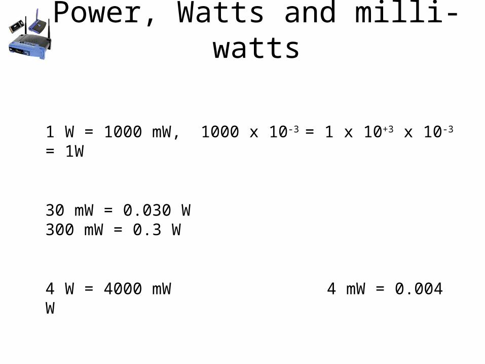
Power, Watts and milli-watts
1 W = 1000 mW, 1000 x 10-3 = 1 x 10+3 x 10-3 = 1W
30 mW = 0.030 W 300 mW = 0.3 W
4 W = 4000 mW 4 mW = 0.004 W

Amplification and Attenuation
• Amplification/Gain - An increase in signal level, amplitude or magnitude of a signal. A device that does this is called an amplifier.
• Attenuation/Loss - A decrease in signal level, amplitude, or magnitude of a signal. A device that does this is called an attenuator.

Amplification
100 mW
RF Amplifier
1 W
SignalSource
AntennaINPUT
OUTPUT
The power gain of the RF amplifier is a power ratio.
Power Gain = = = 10 no unitsPower Output
Power Input
1 W
100 mW
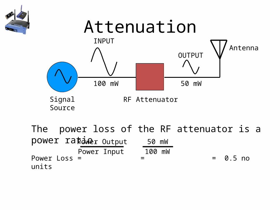
Attenuation
100 mW
RF Attenuator
50 mW
SignalSource
AntennaINPUT
OUTPUT
The power loss of the RF attenuator is a power ratio.
Power Loss = = = 0.5 no unitsPower Output
Power Input
50 mW
100 mW

Decibels
• The decibel is defined as one tenth of a bel where one bel is a unit of a logarithmic power scale and represents a difference between two power levels.
Px and Pref or Pout and Pin
The definition of a dB is:dB = 10 log10( Px / Pref)

Relative and Absolute dB
• Relative dB is selecting any value for PRef
dB
• Absolute dB is selecting a standard value for PRef and identifying the standard value with one or more letter following the dB variable.
dBm dBW dBV dBspl

What are log’s ?
• log’s or logarithms are way of representing a large range of numeric values. http://en.wikipedia.org/wiki/Logarithm http://www.math.utah.edu/~pa/math/log.html
– Very small numbers and very large numbers• The logarithm of a number y with respect to a base b is the
exponent to which we have to raise b to obtain y. • We can write this definition as • x = logby <---> bx = y and we say that x is the logarithm of y with
base b if and only if b to the power x equals y.
Ex. b=10, Y=100, x=2, b=10, Y=100,000, b=5Ex. b=10, Y=.01, x=-2, b=10, Y=1/100,000, b=-5
04/18/23 Wireless Networking J. Bernardini 41

dB gain Sample Problem
100 mW
RF Amplifier
1 W
SignalSource
AntennaINPUT
OUTPUT
Compute the relative power gain of the RF Amplifier in dB.
dB = 10 log10 ( 1W / 100 mW) = 10 log10 ( 10 ) = 10 ( 1 ) = 10 dB
PRef

dB loss Sample Problem
100 mW
RF Attenuator
50 mW
SignalSource
AntennaINPUT
OUTPUT
Compute the relative power loss of the RF Amplifier in dB.
dB = 10 log10 ( 50 mW / 100 mW) = 10 log10 ( .5 ) = 10 ( -0.3 ) = -3.0 dB
PRef

dB Gain Sample Problem
dBm = 10 log10 ( 10 mW / 1 mW) = 10 log10 ( 10 ) = 10 ( 1 ) = 10 dBm
PRef
5 mW
RF Amplifier
10 mW
SignalSource
AntennaINPUT
OUTPUT
Compute the absolute dBm power level at the output of the RF Amplifier.
dB = 10 log10 ( 10 mW / 5 mW) = 10 log10 ( 2 ) = 10 ( 0.3 ) = 3 dB
PRef

Helpful Hints
• dB’s are additive• loss = -dB• gain = +dB• For Power
– A doubling or halving is 3 dB– A ten times or one-tenth is 10 dB
in out3dB -2dB 6dB 2dB -1dB
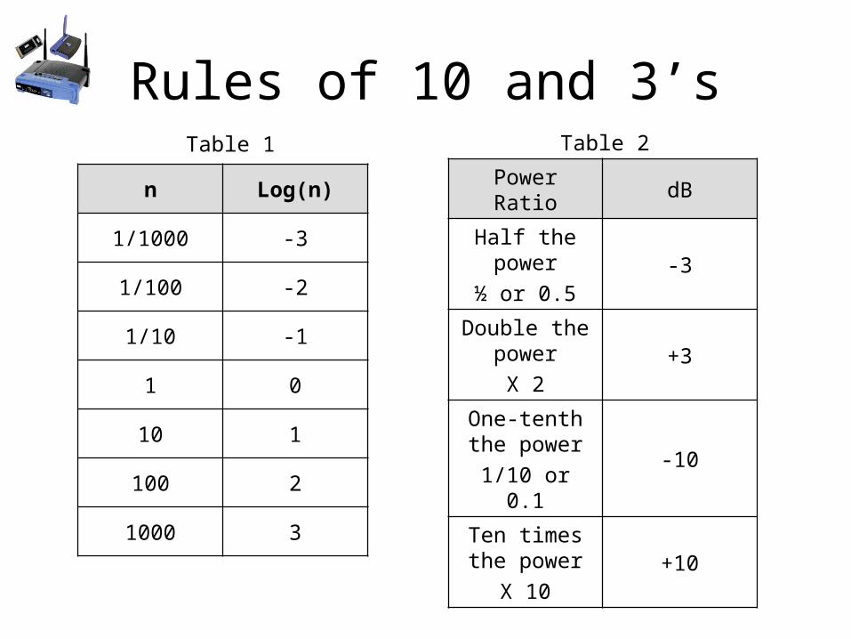
Rules of 10 and 3’s
n Log(n)
1/1000 -3
1/100 -2
1/10 -1
1 0
10 1
100 2
1000 3
Table 1
Power Ratio dB
Half the power
½ or 0.5-3
Double the power
X 2+3
One-tenth the power
1/10 or 0.1-10
Ten times the power
X 10+10
Table 2

Using rules of 10’s and 3’s
04/18/23 Wireless Networking J. Bernardini 47
How do you estimate dB gain when the values are not multiples of 2 and 10?Given a value of dB, come up with a series of 10’s and 3’s that when added equals the given dB.
10x1/2x1/2x1/2 =1.25
2x2x2x2x1/10 = 1.602
10x10x1/2x1/2x1/2x1/2 = 6.25

dB Sample Problem
36 dBm = 10 log10 ( PX / 1 mW) 3.6 = log10 ( PX / 1 mW)
antilog (3.6) = antilog log10( PX / 1 mW) 3,980 = ( PX / 1 mW)
3,980 x 1 mW = PX PX = 3.98 W 4 W
36 dBm = (10 + 10 + 10 + 3 +3)dB, 1 mW x 10 x 10 x 10 = 1W x 2 x 2 = 4 W
RF AmplifierSignalSource
Antenna
Compute the power level in watts at the output of the RF Amplifier.
36 dBm
RF PowerMeter

dB Sample Problem
RF AmplifierSignalSource
Antenna
Compute the power level in watts at the output of the RF Amplifier.
14 dBm
RF PowerMeter
14 dBm = (10 + 3 +1)dB 1mW x 10 = 10mW x 2 = 20mW > 20mW
Actual Value = 25.1 mW a. 10 mW
b. 25 mW
c. 50 mW
d. 100 mW
1 dB = (10 – 9)dB
1 dB = 10 x 0.5 x 0.5 x 0.5 = 1.25
1 mW x 10 x 2 x 1.25 = 25 mW

Antenna Gain• Antenna Gain - is a measure of the ability
of the antenna to focus radio waves in a particular direction. It is the ratio of the power required at the input of a reference antenna to the power supplied to the input of the given antenna to produce the same field strength at the same location.
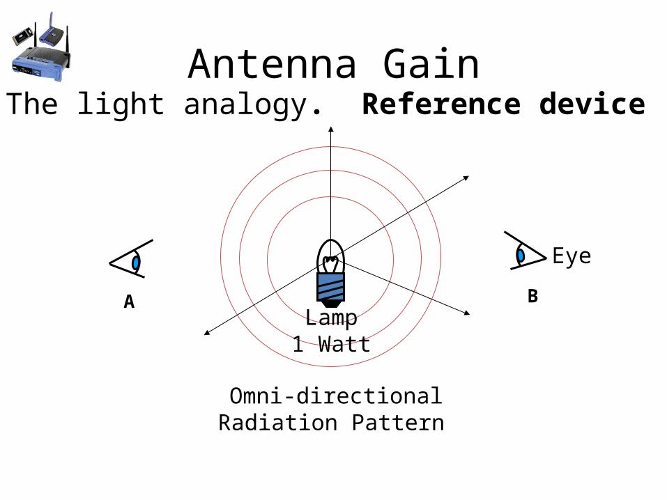
Antenna GainThe light analogy. Reference device
Omni-directionalRadiation Pattern
Lamp1 Watt
Eye
A B

Antenna GainThe light analogy. Focus/Field Strength
DirectionalRadiation Pattern
Lamp1 Watt
Eye
Reflector
A B

Two reference Antennas• Isotropic Antenna - A hypothetical antenna that
radiates or receives energy equally in all directions.
dBi or Gi
• Dipole Antenna - a straight, center-fed, one-half wavelength antenna.
dBd or Gd

EIRP• EIRP - The product of the power supplied to
the antenna and the antenna gain in a given direction relative to a reference isotropic antenna.
EIRP = Pin X Gi
1.58 W = 100 mW x 15.8
AP100 mW
12 dBi = 15.8
Antenna
12 dBi = (3 + 3 + 3 + 3) dBi, 2 x 2 x 2 x 2 = 16

dB Sample Problem
Access Point20 dBm Output
Point A Point B
L
Antenna
Cable loss = - 1.3 dB
Power at point A is 20 dBm = 100 mW
Power at point B is 20 dBm – 1.3 dB = 18.7 dBm = 74.1 mW
Windows calculator: Input 10 press x^y input 1.87 and press Enter Key = 74.13

EIRP ExampleAccess Point
20 dBm Output
Point A Point B
Parabolic Antenna24 dbi
Cable loss = - 1.3 dB
Power at point A is 20 dBm = 100 mW
Power at point B is 20 dBm – 1.3 dB = 18.7 dBm = 74.1 mW
EIRP at point C is 74.1 mW x 251 = 18.6 W
Another method:0dBm +20db-1.3dB+24dB = 42.7 dBm= 40 dB + 3dBApproximately = 1mw x 10,000 x 2 =20 mw
Point C
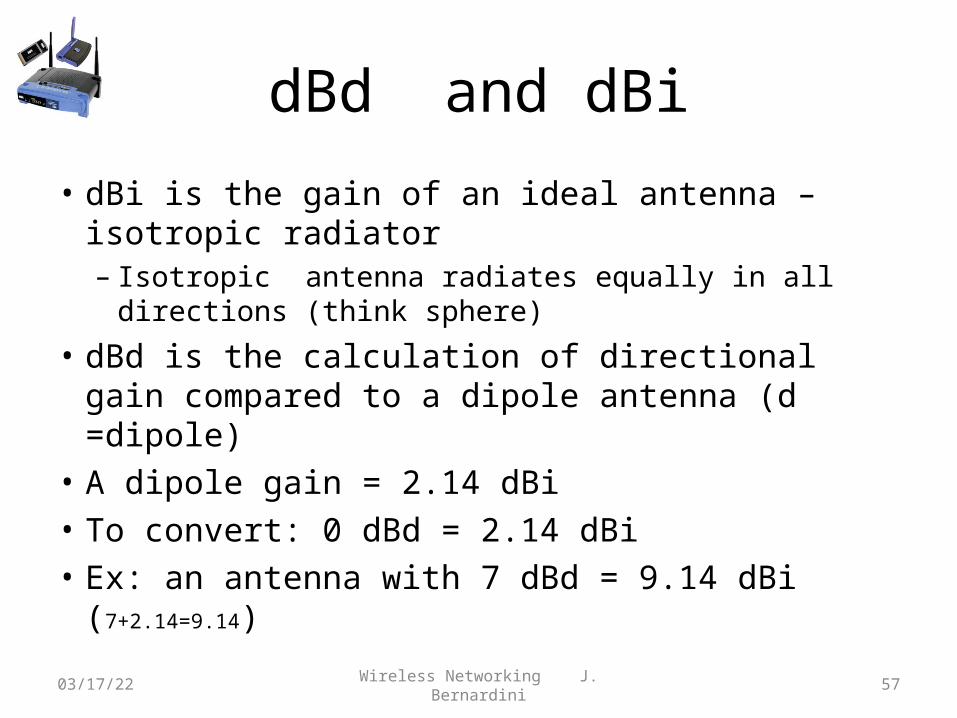
dBd and dBi
• dBi is the gain of an ideal antenna – isotropic radiator– Isotropic antenna radiates equally in all directions
(think sphere)
• dBd is the calculation of directional gain compared to a dipole antenna (d =dipole)
• A dipole gain = 2.14 dBi• To convert: 0 dBd = 2.14 dBi• Ex: an antenna with 7 dBd = 9.14 dBi (7+2.14=9.14)04/18/23 Wireless Networking J. Bernardini 57

SNR and RSSI
• SNR is Signal to Noise Ratio• The RF signal power relative the background noise
level –expressed in dB’s• Important measure of signal strength and the
reliability of the connection• RSSI is Received Signal Strength Indicator• An arbitrary measurement of received signal
strength defined by IEEE 802.11• Not all vendors use the range of values04/18/23 Wireless Networking J. Bernardini 58

RSSI
• Received Signal Strength Indication. RSSI is a measurement of the strength (not necessarily the quality) of the received signal strength in a wireless environment, in arbitrary units.
Note: Cisco Systems RSSI range is 0 to 100. An Atheros based card’s range is 0 to 60. RSSI may be one byte values for 256 levels.

Link Budget and System Operating Margin
• Link budget is an accounting of gains and losses of all RF components. Includes:– Gain, loss, receiver sensitivity, fade margin, cable loss,
connectors, antenna gain and free space loss– Fade Margin –signal loss due to weather, trees other
variables
• System Operating Margin (SOM) is the amount of received signal strength (S)relative to the client device’s receiver sensitivity (RS)
SOM = RS – SEx: RS= -94 dBm, S= -65 dBm SOM = (-94) –(-65) =-29dBm This means
the signal (S) can in theory weaken by 29 dB and the system will work?
60

Link Budget Calculation
61
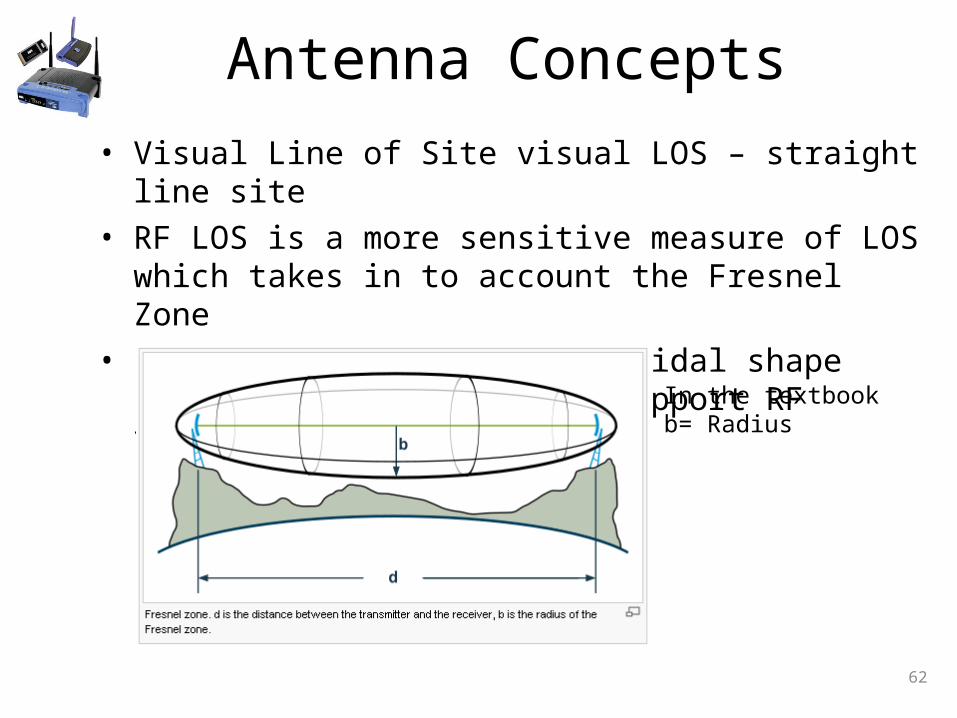
Antenna Concepts• Visual Line of Site visual LOS – straight line site• RF LOS is a more sensitive measure of LOS which takes in to
account the Fresnel Zone• Fresnel Zone is the ellipsoidal shape (foot ball) necessary to
support RF transmission
62
In the textbook b= Radius

Fresnel Calculations
• Good link is: http://www.vias.org/wirelessnetw/wndw_04_08b.html
• Textbook error p.87
• Correct equation Radius = 72.2 x SQRT (D/(4xF))
63