wireless & personal communication systems – cse5807 lecture: 03 1 wireless personal...
Post on 22-Dec-2015
226 views
TRANSCRIPT

1Wireless & Personal Communication Systems – CSE5807Lecture: 03
Wireless Personal Communications Systems – CSE5807
Lecture: 03
Stephen Giles and Satha K. Sathananthan
School of Computer Science and Software Engineering
Monash University
Australia
Modified by Peter Granville August 2006
These slides contain figures from Stallings, and are based on a set developed by Tom Fronckowiak .

2Wireless & Personal Communication Systems – CSE5807Lecture: 03
Access Technologies
Base station
Downlink / Forward ChannelUplink / Reverse Channel
• Responsible for interacting with the medium (wireless channel) to coordinate the successful operation of multiple terminals.
• Separation between uplink and downlink:- Frequency Division Duplexing (FDD):
Uplink and downlink channels use different carrier frequencies.
- Time Division Duplexing (TDD)Uplink and downlink channels use same frequency band but
different time slots.

3Wireless & Personal Communication Systems – CSE5807Lecture: 03
Access Technologies
• Fixed-Assignment Access: Voice-oriented Networks– Frequency Division Multiple Access (FDMA)
– Time Division Multiple Access (TDMA)
– Code Division Multiple Access (CDMA)
• Random or Dynamic Access: Data-oriented Networks
– Aloha Techniques
– Carrier Sense Multiple Access Techniques (CSMA)

4Wireless & Personal Communication Systems – CSE5807Lecture: 03
Access Technologies
ReservationCollision Resolution
e.g.: Pure Aloha
Fixed Allocation
e.g.: FDMA & TDMA
Dynamic Allocation
Use of round-robin ordering
e.g.: Token ring, token bus
Use of collision resolution with implicit reservation
e.g.: CSMA/CD

5Wireless & Personal Communication Systems – CSE5807Lecture: 03
Frequency Division Multiple Access (FDMA)
• Based on Frequency Division Multiplexing (FDM).
• All users transmit signal simultaneously, and they are separated from one another from by their frequency of operation.
Time
FrequencyF1 F2
F3 F4F5
• Used in most of the First Generation (1G) cellular networks.– AMPS (Advanced Mobile Phone Service) system allocates 30 kHz of
bandwidth for each forward and reverse channel.

6Wireless & Personal Communication Systems – CSE5807Lecture: 03
Frequency Division Multiple Access (FDMA)
• Adjacent channel interference – Use of guard bands..
– Power control.
• TDD and FDD:
Time
FrequencyF1 F2 F3 F1 F2 F3Uplink Downlink
Time
FrequencyF1 F2F3 F4
Uplink
Downlink
FDMA/FDD FDMA/TDD
7Wireless & Personal Communication Systems – CSE5807Lecture: 03
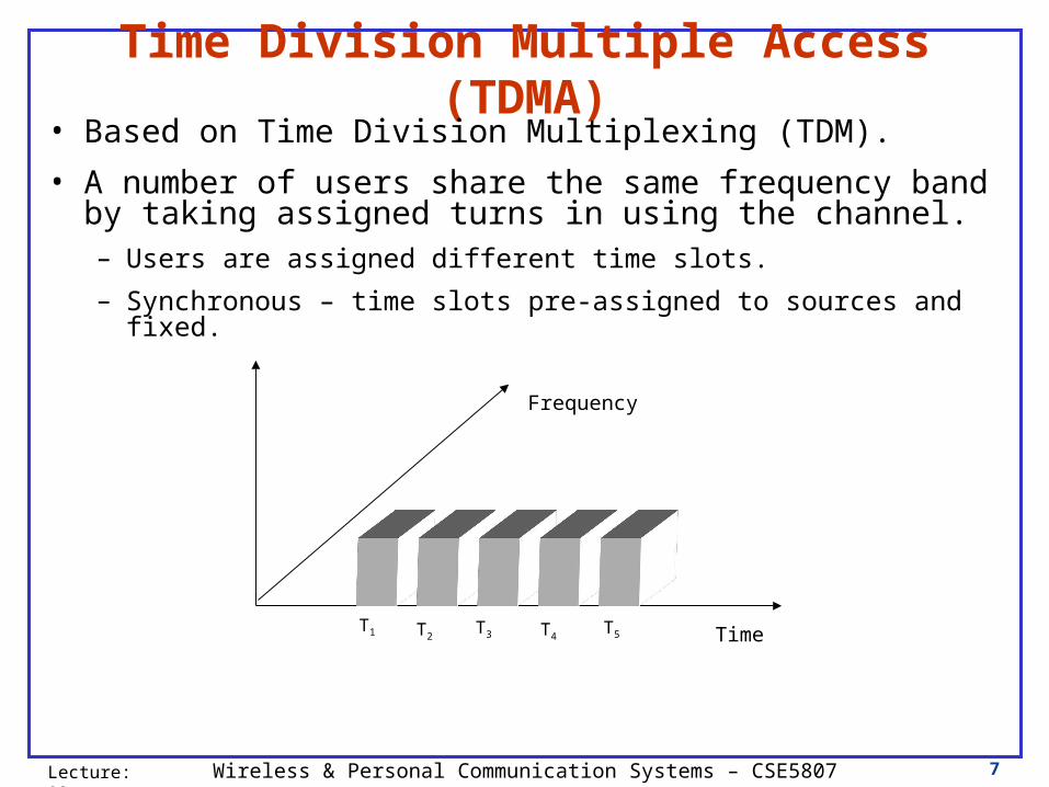
Time Division Multiple Access (TDMA)
• Based on Time Division Multiplexing (TDM).
• A number of users share the same frequency band by taking assigned turns in using the channel.– Users are assigned different time slots.
– Synchronous – time slots pre-assigned to sources and fixed.
Frequency
TimeT1 T2T3 T4
T5
8Wireless & Personal Communication Systems – CSE5807Lecture: 03
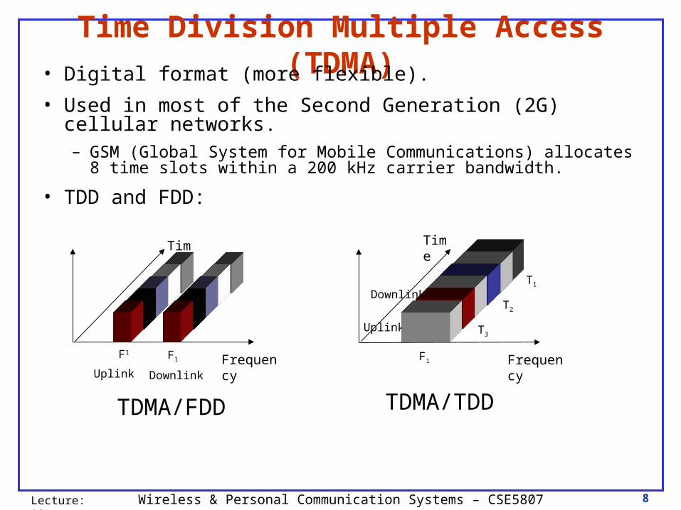
Time Division Multiple Access (TDMA)• Digital format (more flexible).
• Used in most of the Second Generation (2G) cellular networks.– GSM (Global System for Mobile Communications) allocates 8 time slots
within a 200 kHz carrier bandwidth.
• TDD and FDD:
Time
FrequencyF1 F1
Uplink Downlink
TDMA/FDD
T2
T3
T1
Downlink
Uplink
Time
FrequencyF1
TDMA/TDD

9Wireless & Personal Communication Systems – CSE5807Lecture: 03
Code Division Multiple Access (CDMA)
• Based on Spread Spectrum technology.
• A number of users use the same band at the same time, and the users are differentiated by a code.
• Accommodate different bandwidth requirements and switching methods without any need for coordination.
• Each user contributes to interference => Power control
C3
C2
C1
Frequency
TimeCode

10Wireless & Personal Communication Systems – CSE5807Lecture: 03
Code Division Multiple Access (CDMA)
• More capacity and better quality.
• Used in 2G and 3G cellular networks.
– 2G: IS-95
– 3G: IMT-2000
• Uses TDD and FDD
Uplink
Downlink
Frequency
Time
CDMA/FDD CDMA/TDD
TimeCode
Uplink Downlink Frequency

11Wireless & Personal Communication Systems – CSE5807Lecture: 03
Random Access Methods• Allocating a single channel among competing users.
• Belongs to a sublayer of the data link layer, called the “Medium Access Control (MAC)” sublayer.
- Each node has a queue of frames to be transmitted.
- Nodes normally send new frames immediately, hoping for no interference from other nodes.
- How frames are transmitted when collision occur?
=> Pure Aloha
=> Slotted Aloha
=> Carrier Sense Multiple Access (CSMA)
=> CSMA/CD
=> CSMA/AD

12Wireless & Personal Communication Systems – CSE5807Lecture: 03
Pure Aloha• Wireless access to a mainframe: “Alohanet”, invented and
demonstrated in 1970 in Hawaii.mainframe
::::
Stations/terminals
wireless (common channel)
• When stations are ready for transmission, they will transmit immediately hoping that other stations will not transmit at the same time.
• If two or more stations transmit at the same time, a transmission collision occurs and the receivers will not be able
to read the transmissions correctly.

13Wireless & Personal Communication Systems – CSE5807Lecture: 03
Pure Aloha
• A sender will generally realize its transmission is unsuccessful, by not receiving an acknowledgement some time after the completion of its transmission. The sender then retransmits the same data frame again.
• Why use such an unreliable method?• Simple – a complicated mechanism will be more difficult and expensive to implement•Chances of transmission collision is small - if small number of terminals.
•Chances of collision increase with load, maximum utilization of channel is18%.

14Wireless & Personal Communication Systems – CSE5807Lecture: 03
Slotted Aloha
• Time on the channel is organized into uniform slots whose size equals the frame transmission time.
• Central clock needed to synchronize all stations
• Stations when they are ready, can only transmit at the beginning of a timeslot. Thus, frames that do overlap will do so totally.
• Maximum utilization of channel increases to 37%
• Slotted Aloha with TDMA:- Also called Reservation-Aloha (R-Aloha)- Used in GSM for initial contact between MS and BS.

15Wireless & Personal Communication Systems – CSE5807Lecture: 03
Carrier Sense Multiple Access (CSMA)
• If the signal propagation time is small compared to frame transmission time, a station should listen
• Carrier Sense - Listen to determine if another transmission is in progress before transmit.
• Reduces collisions - will only occur when two stations begin to transmit (almost) simultaneously
• Increased utilization of channel.
• non-persistent CSMA:When terminals sense a busy channel as they are ready, they will backoff for a while and return back to sense the channel some time later.

16Wireless & Personal Communication Systems – CSE5807Lecture: 03
CSMA – What should a station do if medium busy ?
• non-persistent CSMA:1. If medium is idle, transmit; else go to 2
2. If medium is busy, wait an amount of time (the retransmission delay) drawn from a probability distribution; go to 1.
– Some capacity wasted
• Random delay reduces the probability of collisions
• 1-persistent CSMA: 1. If medium is idle, transmit; else go to 2
2. If medium is busy, continue to listen until channel is sensed idle; then transmit immediately (with p = 1)
– If two stations are waiting to transmit, a collision will occur.

17Wireless & Personal Communication Systems – CSE5807Lecture: 03
CSMA – What should a station do if medium busy ?
• p-persistent CSMA:1. If medium is idle, transmit with probability p, and delay one time unit
with probability (1 – p). The time unit is equal to maximum propagation delay.
2. If medium is busy, continue to listen until the channel is idle, to go 1.
3. If transmission is delayed 1 time unit, after waiting, go to 1.

18Wireless & Personal Communication Systems – CSE5807Lecture: 03
Carrier Sense Multiple Access/Collision Detection (CSMA/CD)
1. If the medium is idle, transmit; else go to 2.
2. If the medium is busy, continue to listen until channel is idle,then transmit immediately
3. If a collision is detected during transmission, transmit a briefjamming signal to assure that all stations know that there hasbeen a collision then cease transmission
4. After transmitting the jamming signal, wait a random amount of time, the backoff, then go to 1.

19Wireless & Personal Communication Systems – CSE5807Lecture: 03
CSMA/CD Operation

20Wireless & Personal Communication Systems – CSE5807Lecture: 03
CSMA/CD with Binary Exponential Backoff
Number of collisions Possible slots forexperienced in the past (c) retransmission
1 to 10 [n+1 to n+2c]11 to 16 [n+1 to n+210]
>16 =ABORT=
collision
n n+1 n+2 n+3 …
time
• For 1 to 10 retransmission attempts, mean value of random delay doubled.• Mean value remains same for 11 to 16
• Ethernet Protocol = 1-p CSMA/CD + BEB
21Wireless & Personal Communication Systems – CSE5807Lecture: 03
CSMA/CD and Wireless LANs
• Collisions consume bandwidth - want to avoid.
• Collision detection requires a station to be able to send data and receive collision signals at the same time, requires more complex electronics in wireless interface card.
• Collisions may not be detected - a station may be hidden from in a wireless environment due to natural obstacles such as mountains or artificial obstacles such as buildings
• The distance between stations in a wireless environment can be great – signal fading could prevent a station hearing a collision

22Wireless & Personal Communication Systems – CSE5807Lecture: 03
Carrier Sense Multiple Access/Collision Avoidance
(CSMA/CA)
• CSMA with Collision Avoidance.• An idle channel must be detected before a transmission can take place.• A receiver must reply with a short ACK to inform the sender that the transmission is successful so that unnecessary retransmission will not occur.

23Wireless & Personal Communication Systems – CSE5807Lecture: 03
Spread Spectrum• Occupies a much wider bandwidth.
• Two types:– Frequency Hopping Spread Spectrum (FHSS)
– Direct Sequence Spread Spectrum (DSSS)
• More robust to interference and interception.– First used in military communication applications and later adopted for
commercial use.
– Superior performance over traditional radio signaling over multipath channel.
• CDMA system offers more flexibility, superior performance and more capacity over FDMA/TDMA based systems.– Adopted for 3G Cellular systems.
• Can be overlaid with other systems operating in the same band.– WLAN operating in unlicensed band.

24Wireless & Personal Communication Systems – CSE5807Lecture: 03
Spread Spectrum
Frequency
PowerNarrowband Signal – High peak power
(Traditional Signal)
Spread Spectrum Signal – Low peak power

25Wireless & Personal Communication Systems – CSE5807Lecture: 03
Spread Spectrum• What can be gained from apparent waste of spectrum?
– Immunity from various kinds of noise and multipath distortion.
– Can be used for hiding and encrypting signals.
– Several users can independently use the same higher bandwidth with very little interference.

26Wireless & Personal Communication Systems – CSE5807Lecture: 03
Frequency Hoping Spread Spectrum (FHSS)
• Signal is broadcast over seemingly random series of radio frequencies.– A number of channels allocated for the FH signal.
– Width of each channel corresponds to bandwidth of input signal.
• Signal hops from frequency to frequency at fixed intervals.– Transmitter operates in one channel at a time.
– Bits are transmitted using some encoding scheme.
– At each successive interval, a new carrier frequency is selected.

27Wireless & Personal Communication Systems – CSE5807Lecture: 03
Frequency Hoping Spread Spectrum (FHSS)
• Large number of frequencies used => Spread Spectrum.
• Channel sequence dictated by spreading code.
• Receiver, hopping between frequencies in synchronization with transmitter, picks up message.
• Advantages:– Eavesdroppers hear only unintelligible blips.
– Attempts to jam signal on one frequency succeed only at knocking out a few bits.
– Results in a system that is quite resistant to jamming.
• Jammer must jam all frequencies.
• With fixed power, this reduces the jamming power in any one frequency band.

28Wireless & Personal Communication Systems – CSE5807Lecture: 03
Direct Sequence Spread Spectrum (DSSS)
• Each bit in original signal is represented by multiple bits in the transmitted signal.
• Spreading code spreads signal across a wider frequency band. – Spread is in direct proportion to number of bits used.
• One technique combines digital information stream with the spreading code bit stream using exclusive-OR.

29Wireless & Personal Communication Systems – CSE5807Lecture: 03
Direct Sequence Spread Spectrum (DSSS)

30Wireless & Personal Communication Systems – CSE5807Lecture: 03
Direct Sequence Spread Spectrum (DSSS)

31Wireless & Personal Communication Systems – CSE5807Lecture: 03
Code-Division Multiple Access (CDMA)

32Wireless & Personal Communication Systems – CSE5807Lecture: 03
Code-Division Multiple Access (CDMA)
• Break each bit into k chips.– Chips are a user-specific fixed pattern
• Chip data rate of new channel = kD where D = rate of original data signal.
• If k=6 and code is a sequence of 1s and -1s
– For a ‘1’ bit, A sends code as chip pattern
• <c1, c2, c3, c4, c5, c6>
– For a ‘0’ bit, A sends complement of code
• <-c1, -c2, -c3, -c4, -c5, -c6>
• Receiver knows sender’s code and performs decoding.
• <d1, d2, d3, d4, d5, d6> = received chip pattern
• <c1, c2, c3, c4, c5, c6> = sender’s code
665544332211 cdcdcdcdcdcddSu

33Wireless & Personal Communication Systems – CSE5807Lecture: 03
CDMA Example
• User A’s code = <1, –1, –1, 1, –1, 1>
– To send a 1 bit use chip pattern <1, –1, –1, 1, –1, 1>
– To send a 0 bit use chip pattern <–1, 1, 1, –1, 1, –1>
• User B’s code = <1, 1, –1, – 1, 1, 1>
– To send a 1 bit = <1, 1, –1, –1, 1, 1>
• Base Station receives chip pattern and applies A’s code
– (A’s code) x (received chip pattern)
• User A ‘1’ bit: 6 ==> 1
• User A ‘0’ bit: -6 ==> 0
• User B receives chip pattern and applies its code, result: 0 ==> unwanted signal; ignored

34Wireless & Personal Communication Systems – CSE5807Lecture: 03
Required Reading
• W. Stallings, “Wireless Communications and Networks” Prentice-Hall, 2000.
>> Chapter 2.5 and Chapter 7
Optional Reference
• K. Pahlavan and K. Krishnamurthy “Principles of Wireless Networks”, Prentice-Hall, 2002.

35Wireless & Personal Communication Systems – CSE5807Lecture: 03
The following slides are for interest ONLY

36Wireless & Personal Communication Systems – CSE5807Lecture: 03
Spreading Sequences• Spreading Sequence Categories:
– PN sequences:• M-sequences – Constructed by using shift registers.
• Gold sequences – Constructed by using two m-sequences.
– Orthogonal codes:• Walsh codes
• Variable-Length Orthogonal codes
• For FHSS systems– PN sequences most common
• For DSSS systems not employing CDMA– PN sequences most common
• For DSSS CDMA systems– PN sequences
– Orthogonal codes
37Wireless & Personal Communication Systems – CSE5807Lecture: 03
PN Sequences• PN generator produces periodic sequence that appears to be
random.
• PN Sequences: – Generated by an algorithm using initial seed.
– Sequence isn’t statistically random but will pass many test of randomness.
– Sequences referred to as pseudorandom numbers or pseudonoise sequences.
– Unless algorithm and seed are known, the sequence is impractical to predict.

38Wireless & Personal Communication Systems – CSE5807Lecture: 03
Orthogonal Codes• Orthogonal codes
– All pairwise cross correlations are zero.
– Fixed- and variable-length codes used in CDMA systems.
– For CDMA application, each mobile user uses one sequence in the set as a spreading code.
• Provides zero cross correlation among all users.
• Types:– Welsh codes
– Variable-Length Orthogonal codes

39Wireless & Personal Communication Systems – CSE5807Lecture: 03
Typical Multiple Spreading Approach• Spread data rate by an orthogonal code (channelization
code).– Provides mutual orthogonality among all users in the same
cell.
• Further spread result by a PN sequence (scrambling code).– Provides mutual randomness (low cross correlation) between
users in different cells.

40Wireless & Personal Communication Systems – CSE5807Lecture: 03
Orthogonal Frequency Division Multiplexing (OFDM)
• Transmission of Data in Parallel on Multiple Subcarriers (or Multiple Frequency Bands).
• Orthogonal Subcarriers.

41Wireless & Personal Communication Systems – CSE5807Lecture: 03
Orthogonal Frequency Division Multiplexing (OFDM)
• Advantages:
• Resistance to Multipath fading
• Spectral Efficiency
• Easy Implementation using FFT chips

42Wireless & Personal Communication Systems – CSE5807Lecture: 03
Orthogonal Frequency Division Multiplexing (OFDM)
• Adopted in several wireless communication system standards.
– Digital Audio Broadcasting (DAB)
– Digital Video Broadcasting (DVB)
– Wireless LAN
• IEEE802.11a and IEEE802.11g (Wi-Fi)
• HiperLAN-1 and HiperLAN-2
– Fixed Broadband Wireless Access Networks
• IEEE802.16 (Wi-Max)
43Wireless & Personal Communication Systems – CSE5807Lecture: 03
OFDM and Multi-Access Technology• Multicarrier-CDMA (MC-CDMA):
– OFDM and CDMA
– Multiple users are separated by CDMA codes.
– It is being considered for 4G Cellular Networks.
• Orthogonal Frequency Division Multiplexing Access (OFDMA).
– Multiple users are assigned group of subcarriers.
– Used in IEEE802.16 networks.

44Wireless & Personal Communication Systems – CSE5807Lecture: 03
Ultra Wide Band (UWB) Transmission
• Transmission of narrow pulses (order of few tenths of a nanosecond) with low power.
– Very wide band (several GHz).
– Can coexist with existing radio systems (in licensed band too).
• Robust to interference and multipath fading.
• Suitable for short-range communication.
– Is being considered for Wireless Personal Area Networks (WPAN).
– May replace Bluetooth?

45Wireless & Personal Communication Systems – CSE5807Lecture: 03
Non-Preemptive Multiple Access (NPMA)
• Used in HiperLAN-1.• Listen before talk (similar to CSMA/CA).• Uses the characteristics of Slotted-Aloha and TDMA.• If a terminal sense a medium free for a certain duration, then it immediately transmits.• If the channel is busy, the terminal goes through three phases when the channel become available.
- Prioritization phase- Contention phase- Transmission phase