wirelesspowertransferfor - download.e-bookshelf.de
TRANSCRIPT


Wireless Power Transfer forElectric Vehicles and Mobile Devices

Wireless Power Transfer forElectric Vehicles and Mobile Devices
Chun T. RimGwangju Institute of Science and Technology, South Korea
Chris MiSan Diego State University, California, USA

This edition first published 2017© 2017 John Wiley & Sons Ltd
All rights reserved. No part of this publication may be reproduced, stored in a retrieval system, or transmitted, in anyformor by anymeans, electronic,mechanical, photocopying, recording or otherwise, except as permitted by law.Adviceon how to obtain permission to reuse material from this title is available at http://www.wiley.com/go/permissions.
The right of Chun T. Rim and Chris Mi to be identified as the authors of this work has been asserted in accordancewith law.
Registered OfficesJohn Wiley & Sons, Inc., 111 River Street, Hoboken, NJ 07030, USAJohn Wiley & Sons Ltd, The Atrium, Southern Gate, Chichester, West Sussex, PO19 8SQ, UK
Editorial OfficeThe Atrium, Southern Gate, Chichester, West Sussex, PO19 8SQ, UK
For details of our global editorial offices, customer services, and more information about Wiley products visit us atwww.wiley.com.
Wiley also publishes its books in a variety of electronic formats and by print-on-demand. Some content that appearsin standard print versions of this book may not be available in other formats.
Limit of Liability/Disclaimer of WarrantyWhile the publisher and authors have used their best efforts in preparing this work, they make no representations orwarranties with respect to the accuracy or completeness of the contents of this work and specifically disclaim allwarranties, including without limitation any implied warranties of merchantability or fitness for a particular purpose.No warranty may be created or extended by sales representatives, written sales materials or promotional statementsfor this work. The fact that an organization, website, or product is referred to in this work as a citation and/orpotential source of further information does not mean that the publisher and authors endorse the information orservices the organization, website, or product may provide or recommendations it may make. This work is sold withthe understanding that the publisher is not engaged in rendering professional services. The advice and strategiescontained herein may not be suitable for your situation. You should consult with a specialist where appropriate.Further, readers should be aware that websites listed in this work may have changed or disappeared between whenthis work was written and when it is read. Neither the publisher nor authors shall be liable for any loss of profit or anyother commercial damages, including but not limited to special, incidental, consequential, or other damages.
Library of Congress Cataloging-in-Publication data is available for this book.
ISBN 9781119329053 (hardback)
Cover Design: WileyCover Images: (electric car) © Chesky_W/Gettyimages;(smartphone and smart watch) © lcs813/Gettyimages
Set in 10/12pt WarnockPro by Aptara Inc., New Delhi, India
10 9 8 7 6 5 4 3 2 1
v
Contents
Preface vii
Part I Introduction
Introduction to Mobile Power Electronics 3
Introduction to Wireless Power Transfer (WPT) 19
Introduction to Electric Vehicles (EVs) 43
Part II Theories for Inductive Power Transfer (IPT)
Coupled Coil Model 53
Gyrator Circuit Model 67
Magnetic Mirror Model 99
General Unified Dynamic Phasor 129
Part III Dynamic Charging for Road-Powered Electric Vehicles (RPEVs)
Introduction to Dynamic Charging 155
History of RPEVs 161
Narrow-Width Single-Phase Power Rail (I-type) 209
Narrow-Width Dual-Phase Power Rail (I-type) 235
Ultra-Slim Power Rail (S-type) 251
Controller Design of Dynamic Chargers 273
Compensation Circuit 287

vi Contents
Electromagnetic Field (EMF) Cancel 313
Large Tolerance Design 337
Power Rail Segmentation and Deployment 357
Part IV Static Charging for Pure EVs and Plug-in Hybrid EVs
Introduction to Static Charging 379
Asymmetric Coils for Large Tolerance EV Chargers 399
DQ Coils for Large Tolerance EV Chargers 425
Capacitive Power Transfer for EV Chargers Coupler 435
Foreign Object Detection 457
Part V Mobile Applications for Phones and Robots
Review of Coupled Magnetic Resonance System (CMRS) 473
Mid-Range IPT by Dipole Coils 491
Long-Range IPT by Dipole Coils 513
Free-Space Omnidirectional Mobile Chargers 529
Two-Dimensional Omnidirectional IPT for Robots 563
Part VI Special Applications of Wireless Power
Magnetic Field Focusing 579
Wireless Nuclear Instrumentation 587
The Future of Wireless Power 607
Index 613
vii
Preface
We cannot talk about wireless power transfer (WPT) without mentioning Nikola Tesla, whocarried out historic experiments on WPT and wireless communications a hundred years ago.Even though he failed in sending wireless power to another continent, he stimulated the idea ofsending electric power wirelessly. Nearly every trial and effort onWPT since then is within thescope or originated from Nikola Tesla’s idea. One of his inventions, the three-phase inductionmotor, is a kind of WPT because the stator and rotor of an induction motor constitute a trans-mitter (Tx) and receiver (Rx) set, forming a transformer. A transformer is also a kind of WPTwhere the primary and secondary windings are the Tx and Rx of a WPT system. It is amaz-ing that a loosely coupled transformer appears in the equivalent circuit of an inductive powertransfer (IPT) system, which is currently the most widely usedWPT technology. Note that ACtransformers made it possible for Nikola Tesla to electrify human society – in the light of this,we can say that WPT has been one of the roots of modern society.The authors of this book have been interested inWPT since 2008, which is just one year after
the renowned experiment by Soljacic at MIT in sending 60 W power wirelessly over a 2.1 mdistance.Dr Chun Rim startedwith IPT for road-powered electric vehicles (RPEVs), when the Partners
for Advance Transit and Highways of California (PATH) team had already shown their RPEVbuses in the 1990s. As a power electronic engineer, he was not fully convinced of the successof RPEVs at first after reviewing a final report on the development of the PATH project. Thelow power efficiency of 60% and small airgap of 7.6 cm of the PATH team looked impracticalfor commercialization. He cannot but mention Dr Nam P. Suh, the former President of KAIST,who insisted that RPEV is one of the most competitive solutions for the commercialization ofelectric vehicles (EVs), compared to purely battery-powered EVs. With his strong support andguidance, the development and commercialization of the Korean version of RPEV, called an on-line electric vehicle (OLEV), had been accelerated. Dr Rim became, fortunately, one of the coremembers of this nationwide project valued at more than $40 million US dollars. He was one ofthe key team members responsible for developing IPT systems for OLEVs and developed fourgenerations of IPT systems for OLEV until 2013, at which time he embarked on independentlydeveloping his own version of the fifth generation IPT system. He has developed U-, W-, I-,and S-type power rails for OLEV buses, sports utility vehicles, and trains. The OLEV bus andtrain were deployed and commercialized in 2014 and 2010, respectively. OLEV was selected asone of ‘The 50 Best Inventions of 2010’ by TIME and ‘The first of 10 Emerging Technologies in2013’ by the World Economic Forum.After succeeding in the development of OLEVs, Dr Rim expanded his research areas inWPT
to stationary EV charging, mobile device charging, robot power, and drone power. In 2013,he showed for the first time that Soljacic’s coupled magnetic resonance of four coils is notnew and can be equivalently degenerated to the conventional IPT of two coils. Moreover, he

viii Preface
demonstrated that a 5 m-long-distance WPT system of 209 W can be achieved by a conven-tional IPT with innovative dipole coils. Recently, he attained 10 W using IPT at 12 m distanceusing the same technology. By adopting cross-dipole coils to IPT, six-degree-of-freedom(6 DoF) mobile power was achieved for the first time for both plane-type Tx and Rx in 2015,enabling the provision of continuous wireless power in free space. A series of dipole-coil-basedIPT that he has developed shows the possibility of replacing canonical loop-coil-based IPT,because the dipole coil reduces the coil dimension of the loop coil from two to one. In this man-ner, two-dimensional dipole coils can generate the same magnetic flux distribution as three-dimensional loop coils. This dimensionless characteristic is crucial for compact and long-rangeapplications such as the Internet of Things (IoT) and wearables. Dr Rim is currently developingspecial purpose WPT technologies such as a wireless slip ring, wireless nuclear instrumenta-tion, and synthesized magnetic field focusing (SMF), which can improve the resolution of amagnetic field by synthesizing individually controlled currents of arrayed coils that he inventedin 2013.Besides new developments in the aforementioned WPT technologies, Dr Rim has also envi-
sioned new theories for WPT, as he found that there are few theories available for WPT.Maxwell equations cannot be directly used for coil design and the magnetic field cancelingproblem of WPT. This is why he has developed a magnetic mirror model for coil design and agyrator circuit model for resonant circuit design inWPT. Phasor transformation that he devel-oped a long time ago has been adopted for the analysis and design of static and dynamic WPT.In parallel, Dr Chris Mi started his independent research inWPT in 2008. In the past 8 years,
his team has developed a number of unique topologies of WPT systems, including the double-sided LCC-compensated topology, the large-power capacitive wireless power transfer (CPT)technology, low-ripple dynamic WPT, etc. The LCC topology reached 8 kW at a 150 mm dis-tance and efficiency ofmore than 96%. The dynamic charging based on the IPT principle had anout-power ripple of less than 5%. The CPT system reached a power level of 2.5 kW at a distanceof 150 mm, with an efficiency of more than 92%. A combined IPT and CPT further improvedthe system efficiency to 96%.WPT is one of the hottest topics being actively studied and is being widely commercialized.
In particular, there has been a rapid expansion ofWPT inmobile phone chargers and stationaryEV chargers, and RPEV has drawn worldwide attention recently. It is broadly expected that theWPT industry will grow persistently in the coming decades.Unfortunately, there are not many books on WPT that comprehensively explain the subject
from fundamental theories to industry applications. One of the reasons is the rapid change oftechnologies in WPT. Even though the authors’ expertise cannot cover all areas of WPT, theyfinally decided to write a WPT book in 2016 as a textbook for the biannual lecture of WirelessPower Electronics at KAIST. Dr Rim is the main author who wrote most of the book except achapter that was written by Dr Mi who also reviewed and edited the whole book. Hence, ‘I’ inthe book means Dr Rim if not specified otherwise.Considering the rapid evolution of WPT, this book should be revised in a few years, but we
hope that the first edition of this book will provide fruitful state-of-the-art technical insightswith a strong basis of theories on WPT. This book is intended to be used as a textbook forgraduate students or senior undergraduate students, but it can also be used as a design andanalysis guide book for industry engineers.The authors hope that the readers of this book learn that engineering requires philosophical
thoughts and fundamental theories. Innovative ideas and century-lasting inventions come fromprofound understanding of design principles and experiments. In particular, engineers shouldneither make too much of experience nor underestimate theories. Actually, people still do not

Preface ix
have sufficiently good theories in WPT for magnetic and electric field estimation when metalor core is involved.In Part I, concepts of mobile power electronics, wireless power, and EVs are briefly
introduced.In Part II, theories for IPT such as the coupled inductor model, gyrator circuit model, mag-
netic mirror model, and general unified dynamic phasor are explained, where the last threetheories are developed by Dr Rim. This part could be difficult for beginners of WPT and canbe skipped until a theoretical background is strongly needed.In Part III, IPTs for RPEVs are widely covered, making this part the most important portion
of the book. From RPEV history to OLEV-IPT, technologies on I-type and S-type as well asspecific design issues, such as the controller, compensation circuit, electromagnetic field can-cel, large tolerance, and power rail segmentation, are extensively explained. Introduction todynamic charging is primarily written by Nam P. Suh, former President of KAIST.In Part IV, IPTs for static charging for EVs are explained. Large tolerance and capacitive
charging, issues are addressed, written by Chris Mi. Foreign object detection techniques areintroduced in this part, which can be used in dynamic charging. Considering the wide body ofliterature on EV charging, this part is relatively short compared to the treatment of dynamiccharging because of the focus on mobile power transfer of this book. Numerous references areprovided for the reader interested in more details on static charging than we have had space toinclude here. However, many design issues in static charging are similar to those in dynamiccharging; therefore, the design principles and issues in Part III can be applicable to this part.Note that the reverse is not true, because static charging is a special form of dynamic chargingwhereas dynamic charging is not just an extension of static charging.In Part V, IPT mobile applications for phones and robots are covered, starting from a review
of a coupled magnetic resonance system. Mid-range and long-range IPT, as well as free spaceomnidirectional IPT by dipole coils, are explained and two-dimension omnidirectional IPT forrobots is addressed.In Part VI, special applications of WPT such as SMF and wireless nuclear instrumentation
are explained and the future of WPT is discussed.A few Questions and Problems are included in each chapter, which are intended to be poten-
tial research topics.In the near future, almost every valuable object including human beings will be connected
to worldwide networks, which is why the IoT has drawn so much attention in transportation,logistics, securities, public services, home appliances, factory automation, military, health care,robots, drones, and many other fields. Because the IoT comprises sensors, communicationdevices, and power sources, WPT will play significantly important roles in the future IoT. Con-sidering relatively mature technologies in sensors and communication, it can be said that
“Wireless power will be crucial to the future of IoT.”
Since this is the first edition of the book, the authors welcome any input and comments fromreaders (http://tesla.gist.ac.kr) and will ensure that any corrections or amendments as neededare incorporated into future editions.The authors are grateful to all those who helped to complete the book. In particular, a large
portion of the material presented is the result of many years of work by the authors as wellas other members of their research groups. Thanks are due to the many dedicated staff andgraduate students whomade enormous contributions and provided supporting material to thisbook.

x Preface
The authors also owe debts of gratitude to their families, who gave tremendous support andmade sacrifices during the process of writing this book.Sincere acknowledgment is made to various sources that granted permission to use cer-
tain materials or pictures in this book. Acknowledgments are included where those materialsappear. The authors used their best efforts to get approval to use those materials that are in thepublic domain and on open Internet web sites. If any of these sources were missed, the authorsapologize for that oversight and will rectify this in future editions of the book if brought to theattention of the publisher. The names of any product or supplier referred to in this book areprovided for information only and are not in any way to be construed as an endorsement (orlack thereof ) of such a product or supplier by the publisher or the authors.Finally, the authors are extremely grateful to JohnWiley & Sons, Ltd and its editorial staff for
giving them the opportunity to publish this book and helping in all possible ways, and to Mr JiH. Kim at KAIST who helped to prepare the manuscript of this book.
January 1, 2017Professor Chun T. Rim, GIST, South Korea
Professor Chris C. Mi, SDSU, USA

Part I
Introduction
This part introduces the concept of mobile power electronics and the very basic knowledgerelated to wireless power transfer. The most fundamental principles and philosophy of mobilepower electronics and wireless power transfer will be explained.
Wireless Power Transfer for Electric Vehicles and Mobile Devices, First Edition. Chun T. Rim and Chris Mi.© 2017 John Wiley & Sons Ltd. Published 2017 by John Wiley & Sons Ltd.


Introduction to Mobile Power Electronics
. General Overview of Mobile Power Electronics
The methods of power transfer for various sources and loads have evolved since the advent ofelectricity in the nineteenth century. As shown in Figure 1.1, more and more loads are movablenow and it has become important to provide seamless power to moving things such as electrictransportation, robots, and electric airplanes. Currently, we mainly rely on electric cords andbatteries to provide power to movables. As we notice daily, smartphones, tablets, and desk-top computers should operate continuously even in the event of disconnection of utility power.The electric cord, however, has a limited range of powering and the battery has a limited time ofpowering; hence, they inevitably accompany anxiety of range and time. It is important to over-come this range and time limitation for movable things. This was the motivation for “mobilepower electronics,” a term the author (Dr Rim) coined in 2010. In this light, the motto of mobilepower electronics can be said to be “to supply electric energy to all movable things freely.”In general, power transfer (PT) can be classified as stationary and mobile depending on the
movement of power receiving (Rx) loads, as shown in Figure 1.2. Stationary PT (SPT) tradi-tionally has been used in the major form of electricity use, which includes fixed SPT of a firmlyunchanged configuration of power systems and detachable SPT of a variable configuration ofpower systems. A majority of power use is still fixed STP such as high-voltage power lines,street lights, and home appliances. Nowadays, detachable STP is more widely used to chargemovable things such as cable-type electric vehicles (EVs) and electric shavers, where an electriccord with a naked contact is used. These types of plugged-in chargers have an inconvenientuser interface and bring exposure to potential danger of electric shock and fire.To copewith the strong demand formobility of Rx loads, variousmobile PT (MPT) technolo-
gies have been studied; they can be further classified as closeMPT and remoteMPT dependingon the range between the power transmitting (Tx) source and the Rx loads. For the closedMPT, the WPT range is usually from a few cm to a few m. It is remarkable that the inductive,capacitive, and conductive PT correspond to L, C, and R circuit components, respectively. Eachclose PT uses inductive coupling, capacitive coupling, and conductive coupling between the Txand Rx. Among the closeMPTs, inductive PT (IPT) has been used widely due to its high powertransfer capability at relatively low frequency, whereas capacitive PT (CPT) is not as commonlyused due to its high operating frequency and small power transfer distance [1, 2]. Note thatconductive PTwas widely used for a century as a practical means formobile PT until the adventof IPT.Among remoteMPT strategies, radio frequency (RF) PT and optical PThave been researched
to extend the range limit of other PT techniques [3, 4]. RF PT uses electromagnetic waves offrequency ranging from MHz to GHz in practice and is quite different from IPT. For example,
Wireless Power Transfer for Electric Vehicles and Mobile Devices, First Edition. Chun T. Rim and Chris Mi.© 2017 John Wiley & Sons Ltd. Published 2017 by John Wiley & Sons Ltd.

Wireless Power Transfer for Electric Vehicles and Mobile Devices
Ligtning Rod
(a) Road-powered electric vehicles (IPT) (b) Wired/RF-powered airplanes
(c) Smartphone charger (IPT) (d) Robots
Upper Blade
Lower Blade
PayloadM/W beam
Atmosphere
GroundShip
Landing Port
Electric Cable
Motor
45 ~ 60°
Figure . Examples of modern movable things that need seamless electric power.
Figure . A general classification of power transfer in terms of mobility, distance, and means of powering.

1 Introduction to Mobile Power Electronics
the Rx power density of RF PT is usually proportional to the inverse of the square of distance,but that of IPT is typically proportional to the inverse of the sixth power of distance becausethe Rx magnetic flux density of IPT is typically proportional to the third power of distance.Furthermore, there is no magnetic coupling between the Tx and Rx devices of the RF PT. Onthe other hand, the tethered PT can provide power over a flexibly long distance if properlydesigned [5, 6]. As depicted in Figure 1.2, wireless PT (WPT) is not only limited to close MPTsuch as IPT and CPT but also remote MPT such as RF PT and optical PT. Furthermore, WPTis not only electrical but also optical or even acoustic.In the era of the ubiquitous, IPT is the most widely used [8, 58]. More mobile devices, home
appliances, industry sensors, and EV chargers are becoming wireless due to their convenience,safety against electric shock, cleanness, and competitive power efficiency and price. Eventually,most devices including wearable devices, ubiquitous sensors, and smart cars will merge to theInternet of Things (IoT) and WPT will play a significantly important role in the realization ofIoT, which includes compact communication devices, sensors, and power sources.
Question 1 (1) How can you classify electric shavers and vacuum cleaners that have a stretch-able cable? (2) Are the items of (1) SPT or MPT? (3) What are the benefits of the classificationof SPT and MPT? (4) Is there any fundamental distinction between SPT and MPT as well asIPT, CPT, RF PT, and Optical PT?
. Brief History of Mobile Power Electronics
We cannot discuss mobile power or wireless power without talking about Nikola Tesla, whohad carried out many experiments onWPT, as shown in Figure 1.3, and invented a “world sys-tem” for “the transmission of electrical energy without wires.” Even though he did not succeedin transmitting wireless power over the continent as he desired, he has inspired numerous engi-neers and scientists with respect to transferring power remotelywithoutwires. Nikola Teslawasthe pioneer of wireless telegraphy, which is known to be competitively invented by GuglielmoMarconi in 1895. There weremany competitors at that time in utilizing electromagnetic waves,which were discovered by Heinrich Hertz in 1886, for telecommunications. Including his work
Figure . Nikola Tesla (1856–1943) and his experiment on WPT.

Wireless Power Transfer for Electric Vehicles and Mobile Devices
Torus
High voltage
capacitor
High voltage
transformer
High voltage
transformer
Torus
Primary
Primary
Spark
gap
HV
capacitor
Spark gapAC mains
Secondary
Secondary
AC mains
Figure . Examples of the Tesla coil, which is a type of resonant transformer (25 kHz–2 MHz), invented in 1891.
on three-phase AC power systems and induction motors, Nikola Tesla made the most signifi-cant contributions to the era of electricity of the twentieth century.Nikola Tesla was very interested in AC magnetic fields, which were the basis of many of his
inventions, such as wireless communications, induction motors, and WPT systems. As easilyrecognized by experienced engineers, magnetic fields are very difficult to deal with comparedto electric fields and electric circuits. The design of magnets and coils is regarded as one of themost challenging tasks in electrical engineering. A Tesla coil, as shown in Figure 1.4, is one ofthe examples that is difficult to design and to understand in terms of its behavior. He inventedthis coil as a means of generating a high-frequency and high-voltage power source and it isstill being used to generate electric sparks. At that time, there were no semiconductor switchesthat could withstand high voltage, so he used a mechanical switch to ignite resonant ringing ofLC circuits. Utilizing the parasitic capacitances and inductances of the secondary transformer,he boosted the resonant voltage to several tens of kV. This “resonant transformer” is a uniquecharacteristic of the Tesla coil and quite different from conventional transformers, which areclose to an ideal transformer. For example, the output voltage of a resonant transformer is notsimply proportional to the turn ratio of primary and secondary windings of the transformerand it usually becomes much higher than the turn ratio when tuned. This strange phenomenonhas been amysterious issue in the design of the Tesla coil and can be explained by theories suchas the coupled inductor model and the gyrator circuit model in Part II of this book.Understanding the Tesla coil is a good start in understandingWPT and gives us many useful
design tips forWPT because the Tesla coil design involves transformer design, coil design, strayinductance and capacitance modeling, compensation circuit design, insulation issues, ground

1 Introduction to Mobile Power Electronics
Figure . A conductively powered tram (left) and its pantograph (right), which is one of the oldest types of MPT.
issues, switching, and snubber circuit design. Nikola Tesla used the Tesla coil in Figure 1.4 forhis wireless power experiments. For graduate students who wish to understand a “resonanttransformer,” I would like to recommend that they make a Tesla coil kit and conduct experi-ments with special caution regarding high-voltage electric shock when operating. Because ofsafety reasons, it is not recommended that young scientists deal with the Tesla coil even if thesource voltage of the experiment kit is only a few volts. For beginners, it will be much easierand safer to carry out a WPT experiment with a two-coil IPT experiment kit.As discussed above, one of the oldest types of MPT is conductive power for trams and trains,
which fetch AC or DC utility power through a detachable pantograph, as shown in Figure 1.5.This conductively powered tram has been used for a century but is being replaced with battery-powered or wireless-powered trams. Because of cumbersome power lines in the air and theproblem of pantograph wear, the conductively powered tram is no longer widely used in urbanareas, but conductive power is still widely used in subway trains and high-speed trains in manycountries due to the absence of an available candidate solution.The last case that I would like to talk about in the history of mobile power electronics is
the tethered electric helicopter, first built and flown by Gustave Trouve in 1887 and developedfor possible military use by the Nazis during World War II. This tethered drone is useful forcontinuous surveillance and watch missions without landing for several hours to several weeksif desired. Considering the rapid growth of dronemarkets, this tethered powering is noteworthyeven though it has no relationship to WPT.Note that MPT is not necessarily WPT but could take many different forms, which will be
discussed in the following section. If we extend our concern to mobile energy transfer, batter-ies as well as petroleum, natural gas, coal, and hydrogen can be the means of energy transfer.In particular, the battery is a good means of electrical energy transfer and an excellent powersource. Thus far, as we are dealing withMPT issues, we need to consider the battery as a meansof delivering power continuously to remote locations as we now daily rely on it.
Question 2 (1) What is energy harvesting? (2) What are the merits and limitations of energyharvesting compared to MPT? (3) Discuss the potential applications of energy harvesting toIoT when combined with MPT.
. Remote Mobile Power Transfer (MPT)
Because the close MPT of Figure 1.2 will be explained in Chapter 2, remote MPT is explainedin this section briefly. One of the purposes of this section is to familiarize readers with otherMPT techniques aside from conventional WPTs.
Wireless Power Transfer for Electric Vehicles and Mobile Devices
Power spot
30 m
Power beam
500–1000 kW
21 m
85 m
Communications
relay 500 km
horizon
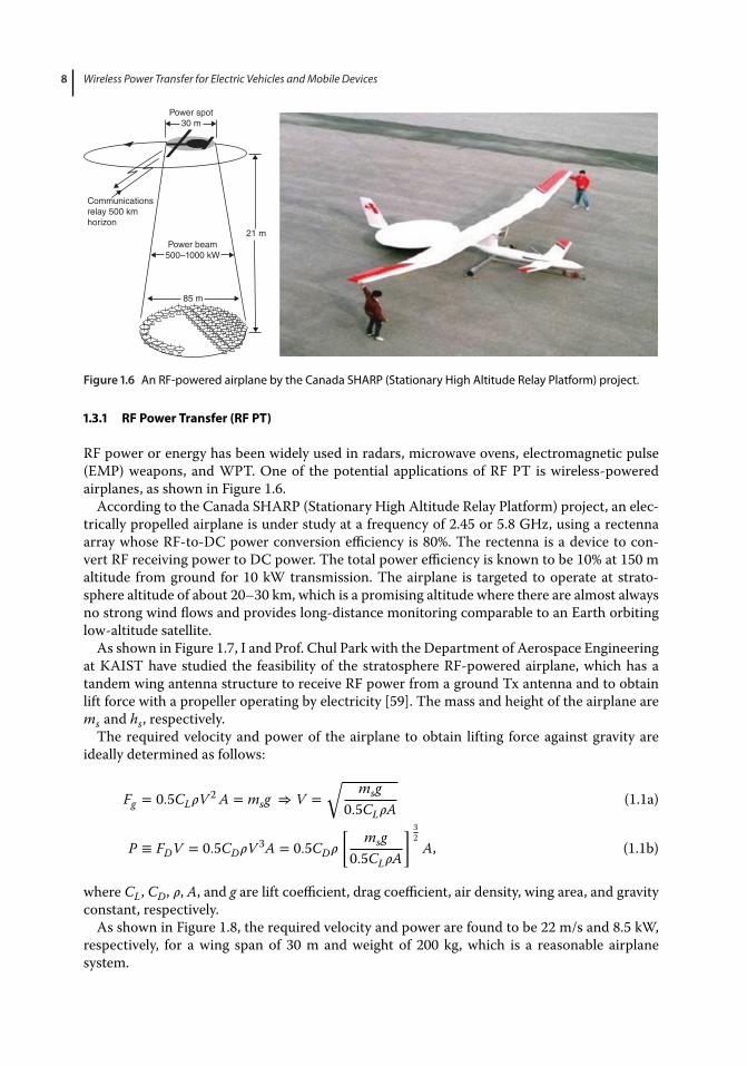
Figure . An RF-powered airplane by the Canada SHARP (Stationary High Altitude Relay Platform) project.
1.3.1 RF Power Transfer (RF PT)
RF power or energy has been widely used in radars, microwave ovens, electromagnetic pulse(EMP) weapons, and WPT. One of the potential applications of RF PT is wireless-poweredairplanes, as shown in Figure 1.6.According to the Canada SHARP (Stationary High Altitude Relay Platform) project, an elec-
trically propelled airplane is under study at a frequency of 2.45 or 5.8 GHz, using a rectennaarray whose RF-to-DC power conversion efficiency is 80%. The rectenna is a device to con-vert RF receiving power to DC power. The total power efficiency is known to be 10% at 150 maltitude from ground for 10 kW transmission. The airplane is targeted to operate at strato-sphere altitude of about 20–30 km, which is a promising altitude where there are almost alwaysno strong wind flows and provides long-distance monitoring comparable to an Earth orbitinglow-altitude satellite.As shown in Figure 1.7, I and Prof. Chul Park with the Department of Aerospace Engineering
at KAIST have studied the feasibility of the stratosphere RF-powered airplane, which has atandem wing antenna structure to receive RF power from a ground Tx antenna and to obtainlift force with a propeller operating by electricity [59]. The mass and height of the airplane arems and hs, respectively.The required velocity and power of the airplane to obtain lifting force against gravity are
ideally determined as follows:
Fg = 0.5CL𝜌V 2 A = msg ⇒ V =√ msg
0.5CL𝜌A(1.1a)
P ≡ FDV = 0.5CD𝜌V 3A = 0.5CD𝜌
[ msg0.5CL𝜌A
] 32A, (1.1b)
where CL, CD, 𝜌, A, and g are lift coefficient, drag coefficient, air density, wing area, and gravityconstant, respectively.As shown in Figure 1.8, the required velocity and power are found to be 22 m/s and 8.5 kW,
respectively, for a wing span of 30 m and weight of 200 kg, which is a reasonable airplanesystem.

1 Introduction to Mobile Power Electronics
M/W
beam
Atmosphere
Wind direction
Tandem
Propeller
wing-antennams
hs
Ground
Figure . An RF-powered airplane designed by KAIST (Chun T. Rim and Chul Park).
As shown in Figure 1.9, the diameter of a ground station to transmit RF power can be calcu-lated for a wing span of 30 m, altitude of 30 km, and RF frequencies of L-band (2.45 GHz) andX-band (10.0 GHz) as follows:
LWS ≅ 𝜆
Dhs =
chsfD
⇒ D ≅chsfLWS
, (1.2a)
D2.45 GHz =chsfLWS
= 3 × 108 ⋅ 30 k2.45 G ⋅ 30
= 122 m (1.2b)
D10 GHz =chsfLWS
= 3 × 108 ⋅ 30 k10 G ⋅ 30
= 30 m (1.2c)
As identified from (1.2b) and (1.2c), the diameters of a ground station for L-band and C-band are 122 m and 30 m, respectively, which are quite reasonable to build. Frequency can beselected considering the ground station size and total power efficiency, where the L-band hashigher power efficiency than the C-band. Considering currently available RF components andpropagation loss, the power requirement of a ground station is found to be roughly 200 kW [59].
80.0 40.0
35.0
30.0
25.0
20.0
15.0
10.0
5.0
0.0
70.0
60.0
50.0
40.0
30.0
20.0
10.0
0.00 20 40 60 80 100
Weight [kg]
Altitude = 30 km
Weight [kg]
120 140 160 180 200 220 240 0
Pow
er
[kW
]
Flig
ht ve
locity [m
/s]
20 40 60 80 100 120 140 160 180 200 220 240
Wing span 50 m40 m30 m20 m10 m Wing span 50 m40 m30 m20 m10 m
Altitude = 30 km
Figure . Required flight velocity (top) and power (bottom) for the given weight of the KAIST RF-poweredairplane.

Wireless Power Transfer for Electric Vehicles and Mobile Devices
8.5 kW
200 kW
hs
D
Lws
Figure . Required ground power and diameter of a ground station ofthe KAIST RF-powered airplane.
It has been outlined that the stratosphere RF airplane can be built if appropriate RF componentsare used and the RF airplane is properly designed.The NASA plan of sending solar power generated at a geostationary orbit satellite through
microwaves started in 1978. It was designed to have 1 km and 10 km diameter Tx and Rx anten-nas at 2.45 GHz to achieve 750MWreceiving power on Earth ground. Experiments at a few kWpower level with reduced size Tx and Rx antennas were conducted at Goldstone in Californiain 1975 and Grand Bassin on Reunion Island in 1997, respectively. This NASA plan was finallycancelled due to several issues such as low Tx efficiency, potentially harmful Rx power density,and extremely poor cost-effectiveness compared to ground solar power generation.Recently, low-power applications of RF PT have been widely explored as the energy source of
distributed sensor networks and IoT. RF energy harvesting [60] is currently a hot issue, wherevery low power of less than 1 mW or a very small amount of energy lower than 1 mJ is pursued.RF power delivery tomobile devices in an office or room is also an interesting application, wheredynamic directing of the Tx antenna and the narrow receiving angle of the Rx antenna of arbi-trarily positionedmobile devices are important problems.Avoiding harmful RF power exposureto the human body and adjacent electronic equipment is also a challenging issue together withexpensive Tx and Rx devices and strong RF interference regulations.
Question 3 (1) What happens to a stratosphere drone with RF PT if the power transfer isabruptly stopped due to breakdown of power systems or bad weather? (2) What are the reme-dies for (1)?
Question 4 (1) Estimate the cost of launching andmaintaining a geostationary satellite for solarpower generation and transmitting. (2) Compare (1) to the cost of a conventional ground solarpower generator.
1.3.2 Optical Power Transfer (Optical PT)
Optical power is a good candidate for wireless power if good clearance between Tx and Rx ismaintained. As shown in Figure 1.10(a), the NASAMarshall Space Flight Center has developeda laser-powered drone whose total power efficiency from the input power of a laser Tx to theoutput power of solar cell is 6.8%. The rationale for this efficiency is as follows:
– Current laser efficiencies of 25% (it can be improved up to 50% in the near future)– Solar cell conversion efficiencies of 50%– Power conditioning efficiency of 80%– Receiver efficiency of 75%– Atmospheric transmission efficiency of 90%.

1 Introduction to Mobile Power Electronics
Figure . (a) NASA laser-powered drone and (b) a climber at the NASA Beam Power Challenge test.
Even though the power efficiency of 6.8% is much lower than that of a modern IPT device, theoptical drone shows the possibility of low-power WPT to indoor mobile devices without anyelectromagnetic interference (EMI) problems. If the wavelength of the laser is infrared (IR), itis quite safe to the human body unless the power level is very high. Like RF PT, this optical PThas the problem of dynamic directing of the Tx and a narrow receiving angle of Rx of arbitrarilypositioned mobile devices. Furthermore, it is very difficult for the optical PT to have electronicbeam steering, which is available for RF PT, although it is expensive and has a limited steeringangle.As shown in Figure 1.10(b), a climber built by the University of Saskatchewan Space Design
Team reached 40 feet up a 200-ft climbing ribbon in the NASA Beam Power Challenge test in2005. Sunlight is free and abundant but is not available in cloudyweather and at night; therefore,an artificial LED or laser light is crucial for an optical PT in order to provide a reliable lightpower source. One of the fundamental drawbacks of optical PT is that power can be deliveredonly in the line of sight and cannot be delivered through obstacles or opaque materials, whichcan be easily overcome by IPT for instance.
Question 5 (1) What would happen to a drone with an optical PT when the power transferis abruptly stopped due to a breakdown of power systems or bad weather? (2) What are theremedies for (1)? Discuss whether an on-board battery is a good solution. (3) What if the angleof incidence to the drone is variable and sometimes extremely large?
1.3.3 Tethered Power Transfer (Tethered PT)
As discussed, tethered PT is suitable for a stationary drone for persistent missions such assurveillance, environment monitoring, fire and crime monitoring, traffic control, communi-cation relay, broadcasting, search and rescue, and video capture. There had not been manystudies when I started to research a tethered unmanned helicopter (UTH) in 2007, as shown inFigure 1.11 [61]. As an example of tethered drones, a summary of this study [61] is provided inthe following.The target altitude, total mass, and total power of the UTH are 1 km, 200 kg, and 25 kW,
respectively, as listed in Table 1.1. A power cable of 1 kV, 25 A ratings is used, where the massand resistance for 1 km of power cable are 95 kg and 12.1 ohms, respectively. Considering a

Wireless Power Transfer for Electric Vehicles and Mobile Devices
(a)
(b)
Lightning Rod
Upper Blade
Lower Blade
FuselageLanding Skid
Electric Cable
Ship
Landing Port
45 ~ 60° Upper Blade
Lower Blade
Lightning Rod
Electric Cable
Payload
Motor
Figure . A tethered helicopter designed by KAIST (ChunT. Rim): (a) configuration and (b) and operation concept.
9.5 kW total power loss including the power cable loss, the delivered power to the UTH is15.5 kW, which is enough power to lift the UTH and to provide for mission payloads.As shown in Figure 1.11, a lightning rod is installed to the UTH, which resulted from the
lesson learnt byNazis when the tethered helicopter failed due to lightning. It is assumed that thecable is wrapped on the ground and a brush contact is installed to have an electric connectionof the cable to the ground power source.Another tethered PT is for ground vehicles, as shown in the example in Figure 1.12(a). This
tethered ground vehicle (TGV) has been developed by my team since 2011. For the TGV, cableis wound on the vehicle and a constant tension is always provided to the cable so that it cantravel around corners without fear of getting stuck. The conventional cabletype ground vehiclecarries the cable but easily becomes stuck at corners.

1 Introduction to Mobile Power Electronics
Table . The mass and power budgets of KAIST UTHdesigned by Chun T. Rim
Items Mass (kg) Power (kW)
TUH platform (lifting) 25 12.0TUH platform (others) 40 0.5TUH payload (radar, IR) 30 1.0Electric cable 95 9.5Design margin 10 2.0Total 200 25.0
Recently, my team has developed tethered drones, where the cable is wound either on theground or on the drone, as shown in Figure 1.12(b) [62]. When the tension control systemis on the drone, it is appropriate for roaming missions; in contrast, when the tension controlsystem is on the ground, it is good for stationary missions. By designing a novel cable wrappingmechanism, there is no brush contact for the ground tension control case [62].
(a) Tethered ground vehicle for surveillance
(b) Tethered drone for environment monitoring
Figure . Tethered ground vehicle and small drone designed by KAIST (Chun T. Rim).

Wireless Power Transfer for Electric Vehicles and Mobile Devices
Question 6 Discuss detail methods for protecting a tethered drone from lightning. (1) Forexample, what about using a current fuse that is blown up when large lightning current flows?(2) How can the tethered electric cable be grounded for lightning current bypass? Rememberthat the wound electric cable under lightning is exposed to an extremely high voltage (∼MV)and may not withstand the electric shock.
. Conclusion
An overview of MPT has been provided in this chapter. The most important competitors inmobile power electronics will be the battery versus WPT. If a very light, small size, cheap, longlasting, and quick chargeable battery is available, then batteries will dominate overWPT. How-ever,WPT is becomingmore important inMPTbecause of the convenience and inherent safetyand batteries need to be recharged.WPT is thus not only a competitor but also an ally of the bat-tery. Moreover, WPT may substitute or dominate the battery, as identified by RPEV. TetheredPT is also a good candidate forMPT andmay provide a replacement for the battery. MostWPTand tethered PT require batteries for their emergency power to provide a reliable power sourceto the system. Therefore, all parts of MPT should be enhanced together to achieve progress inmobile power electronics.
References
M. Kline, I. Izyumin, B. Boser, and S. Sanders, “Capacitive power transfer for contactlesscharging,” in 2011 ECCE Conference, pp. 1398–1404.
B. Choi, D. Nguyen, S. Yoo, J. Kim, and C. Rim, “A novel source-side monitored capacitivepower transfer system for contactless mobile charger using class-E converter,” in 2014 VTCConference, pp. 1–5.
E.Y. Chow, “Wireless powering and the study of RF propagation through ocular tissue fordevelopment of implantable sensors,” IEEE Trans. Antennas Propag., vol. 59, no. 6,pp. 2379–2387, June 2011.
N. Wang et al., “One-to-multipoint laser remote power supply system for wireless sensornetworks,” IEEE Sensors J., vol. 12, no. 2, pp. 389–396, February 2012.
I. Shnaps and E. Rimon, “Online coverage by a tethered autonomous mobile robot in planarunknown environments,” IEEE Trans. Robot., vol. 30, no. 4, pp. 966–974, August 2014.
S. Choi et al., “Tethered aerial robots using contactless power systems for extended missiontime and range,” in 2014 ECCE Conference, pp. 912–916.
O.C. Onar, J. Kobayashi, and A. Khaligh, “A fully directional universal power electronicinterface for EV, HEV, and PHEV applications,” IEEE Trans. Power Electron., vol. 28, no. 12,pp. 5489–5498, December 2013.
E. Waffenschmidt, “Free positioning for inductive wireless power system,” in 2011 ECCEConference, pp. 3481–3487.
W. Zhong, X. Liu, and S. Hui, “A novel single-layer winding array and receiver coil structure forcontactless battery charging systems with free-positioning and localized charging features,”IEEE Trans. Ind. Electron., vol. 58, no. 9, pp. 4136-4143, September 2011.
C. Park, S. Lee, G. Cho, S. Choi, and Chun T. Rim, “Omni-directional inductive power transfersystem for mobile robots using evenly displaced multiple pick-ups,” in 2012 ECCE Conference,pp. 2492–2497.

1 Introduction to Mobile Power Electronics
C. Park, S. Lee, G. Cho, S. Choi, and Chun T. Rim, “Two-dimensional inductive power transfersystem for mobile robots using evenly displaced multiple pickups,” IEEE Trans. Ind. Appl.,vol. 50, no. 1, pp. 538–565, June 2013.
B. Che et al., “Omnidirectional non-radiative wireless power transfer with rotating magneticfield and efficiency improvement by metamaterial,” Appl. Phys. A, vol. 116, no. 4,pp. 1579–1586, April 2014.
W. Ng, C. Zhang, D. Lin, and S. Hui, “Two- and three-dimensional omnidirectional wirelesspower transfer,” IEEE Trans. Power Electron., vol. 29, no. 9, pp. 4470–4474, January 2014.
H. Li, G. Li, X. Xie, Y. Huang, and Z. Wang, “Omnidirectional wireless power combinationharvest for wireless endoscopy,” in 2014 BioCAS Conference, pp. 420–423.
X. Li et al., “A new omnidirectional wireless power transmission solution for the wirelessendoscopic micro-ball,” in 2011 ISCAS Conference, pp. 2609–2612.
R. Carta et al., “Wireless powering for a self-propelled and steerable endoscopic capsule forstomach inspection,” Biosens. Bioelectron., vol. 25, no. 4, pp. 845–851, December 2009.
T. Sun et al., “Integrated omnidirectional wireless power receiving circuit for wirelessendoscopy,” Electron. Lett., vol. 48, no. 15, pp. 907–908, July 2012.
B. Lenaerts and R. Puers, “An inductive power link for a wireless endoscope,” Biosens.Bioelectron., vol. 22, no. 7, pp. 1390–1395, February 2007.
B. Choi, E. Lee, J. Kim, and Chun T. Rim, “7m-off-long-distance extremely loosely coupledinductive power transfer system using dipole coils,” in 2014 ECCE Conference, pp. 858–863.
C. Park, S. Lee, G. Cho, and Chun T. Rim, “Innovative 5-m-off-distance inductive powertransfer systems with optimally shaped dipole coils,” IEEE Trans. Power Electron., vol. 30, no. 2,pp. 817–827, November 2014.
Chun T. Rim and G. Cho, “New approach to analysis of quantum rectifier-inverter,” Electron.Lett., vol. 25, no. 25, pp. 1744–1745, December 1989.
Chun T. Rim, “Unified general phasor transformation for AC converters,” IEEE Trans. PowerElectron., vol. 26, no. 9, pp. 2465–2475, September 2011.
J. Huh, W. Lee, S. Choi, G. Cho, and Chun T. Rim, “Frequency-domain circuit model andanalysis of coupled magnetic resonance systems,” J. Power Electron., vol. 13, no. 2, pp. 275–286,March 2013.
A. Kurs, A. Karalis, R. Moffatt, J.D. Joannopoulos, P. Fisher, and M. Soljacic, “Wireless powertransfer via strongly coupled magnetic resonance,” Science, vol. 317, no. 5834, pp. 83–86, June2007.
A.P. Sample, D.A. Meyer, and J.R. Smith, “Analysis, experimental results, and range adaption ofmagnetically coupled resonators for wireless power transfer,” IEEE Trans. Ind. Electron., vol. 58,no. 2, pp. 544–554, February 2011.
T. Imura and Y. Hori, “Maximizing air gap and efficiency of magnetic resonant coupling forwireless power transfer using equivalent circuit and Neumann formula,” IEEE Trans. Ind.Electron., vol. 58, no. 10, pp. 4746–4752, October 2011.
T.C. Beh, T. Imura, and Y. Hori, “Basic study of improving efficiency of wireless power transfervia magnetic resonance coupling based on impedance matching,” in 2010 ISIE Conference,pp. 2011–2016.
J. Park, Y. Tak, Y. Kim, Y. Kim, and S. Nam, “Investigation of adaptive matching methods fornear-field wireless power transfer,” IEEE Trans. Antennas Propag., vol. 59, no. 5, pp. 1769–1773,May 2011.
J. Huh, W.Y. Lee, S.Y. Choi, G.H. Cho, and Chun T. Rim, “Explicit static circuit model ofcoupled magnetic resonance system,” in 2011 ECCE-Asia Conference, pp. 2233–2240.
E. Lee, J. Huh, X.V. Thai, S. Choi, and Chun T. Rim, “Impedance transformers for compact androbust coupled magnetic resonance systems,” in 2013 ECCE Conference, pp. 2239–2244.

Wireless Power Transfer for Electric Vehicles and Mobile Devices
R. Hui, W. Zhong, and C. Lee, “A critical review of recent progress in mid-range wireless powertransfer,” IEEE Trans. Power Electron., vol. 29, no. 9, pp. 4500–4511, September 2014.
G. Covic, M. Kissin, D. Kacprzak, N. Clausen, and H. Hao, “A bipolar primary pad topology forEV stationary charging and highway power by inductive coupling,” in 2011 ECCE Conference,pp. 1832–1838.
S. Li and C. Mi, “Wireless power transfer for electric vehicle applications,” IEEE Trans. Emerg.Sel. Topics Power Electron., vol. 3, no. 1, pp. 4–17, March 2015.
S. Choi, J. Huh, W. Lee, and Chun T. Rim, “Asymmetric coil sets for wireless stationary EVchargers with large lateral tolerance by dominant field analysis,” IEEE Trans. Power Electron.,vol. 29, no. 12, pp. 6406–6420, December 2014.
M. Budhia, G. Covic, and J. Boys, “Design and optimization of circular magnetic structures forlumped inductive power transfer systems,” IEEE Trans. Power Electron., vol. 26, no. 11,pp. 3096–3108, November 2011.
M. Budhia, J. Boys, G. Covic, and C. Huang, “Development of a single-sided flux magneticcoupler for electric vehicle IPT charging systems,” IEEE Trans. Ind. Electron., vol. 60, no. 1,pp. 318–328, January 2013.
T. Nguyen, S. Li, W. Li, and C. Mi, “Feasibility study on bipolar pads for efficient wireless powerchargers,” in 2014 APEC Conference, pp. 1676–1682.
P. Meyer, P. Germano, M. Markovic, and Y. Perriard, Design of a contactless energy-transfersystem for desktop peripherals,” IEEE Trans. Ind. Applic., vol. 47, no. 4, pp. 1643–1651, July2011.
J. Shin et al., “Design and implementation of shaped magnetic-resonance-based wireless powertransfer system for roadway-powered moving electric vehicles,” IEEE Trans. Power Electron.,vol. 61, no. 3, pp. 1179–1192, March 2014.
G. Elliott, J. Boys, and G. Covic, “A design methodology for flat pick-up ICPT systems,” in 2006ICIEA Conference, pp. 1–7.
S. Lee et al., “On-line electric vehicle using inductive power transfer system,” in 2010 ECCEConference, pp. 1598–1601.
J. Huh, S. Lee, C. Park, G. Cho, and Chun T. Rim, “High performance inductive power transfersystem with narrow rail width for on-line electric vehicles,” in 2010 ECCE Conference,pp. 647–651.
J. Huh, W. Lee, B. Lee, G. Cho, and Chun T. Rim, “Characterization of novel inductive powertransfer systems for on-line electric vehicles,” in 2011 APEC Conference, pp. 1975–1979.
J. Huh, S. Lee, W. Lee, G. Cho, and Chun T. Rim, “Narrow-width inductive power transfersystem for on-line electrical vehicles,” IEEE Trans. Power Electron., vol. 26, no. 12,pp. 3666–3679, December 2011.
S. Lee et al., “Active EMF cancellation method for I-type pickup of on-line electric vehicles,” in2011 APEC Conference, pp. 1980–1983.
W. Lee et al., “Finite-width magnetic mirror models of mono and dual coils for wireless electricvehicles,” IEEE Trans. Power Electron., vol. 28, no. 3, pp. 1413–1428, March 2013.
S. Choi, J. Huh, W. Lee, S. Lee, and Chun T. Rim, “New cross-segmented power supply rails forroad powered electric vehicles,” IEEE Trans. Power Electron., vol. 28, no. 12, pp. 5832–5841,December 2013.
S. Lee, B. Choi, and Chun T. Rim, “Dynamic characterization of the inductive power transfersystem for online electric vehicles by Laplace phasor transform,” IEEE Trans. Power Electron.,vol. 28, no. 12, pp. 5902–5909, December 2013.
S. Choi, B. Gu, S. Jeong, and Chun T. Rim, “Ultra-slim S-type inductive power transfer systemfor road powered electric vehicles,” in 2014 EVTeC Conference, pp. 1–7.

1 Introduction to Mobile Power Electronics
S. Choi et al., “Generalized active EMF cancel methods for wireless electric vehicles,” IEEETrans. Power Electron., vol. 29, no. 11, pp. 5770–5783, November 2014.
C. Wang, O. Stielau, and G. Covic, “Design considerations for a contactless electric vehiclebattery charger,” IEEE Trans. Ind. Electron., vol. 52, no. 5, pp. 1308–1314, October 2005.
C. Wang, G. Covic, and O. Stielau, “Power transfer capability and bifurcation phenomena ofloosely coupled inductive power transfer systems,” IEEE Trans. Ind. Electron., vol. 51, no. 1,pp. 148–157, February 2004.
G. Covic and J. Boys, “Modern trends in inductive power transfer for transportationapplications,” IEEE Trans. Emerg. Sel. Topics Power Electron., vol. 1, no. 1, pp. 28–41, March2013.
O. Onar et al., “A novel wireless power transfer for in-motion EV/PHEV charging,” in 2013APEC Conference, pp. 2073–3080.
S. Choi, B. Gu, S. Jeong, and Chun T. Rim, “Advances in wireless power transfer systems forroadway-powered electric vehicles,” IEEE Trans. Emerg. Sel. Topics Power Electron., vol. 3, no. 1,pp. 18–35, March 2015.
B. Lee, H. Kim, S. Lee, C. Park, and Chun T. Rim, “Resonant power shoes for humanoid robots,”in 2011 ECCE Conference, pp. 1791–1794.
B. Choi, E. Lee, J. Huh, and Chun T. Rim, “Lumped impedance transformers for compact androbust coupled magnetic resonance systems,”IEEE Trans. Power Electron., vol. PP, no. 99, pp. 1,January 2015 (Early access article).
J. Kim et al., “Coil design and shielding methods for a magnetic resonant wireless powertransfer system,” Proc. IEEE, vol. 101, no. 6, pp. 1332–1342, June 2013.
Chun T. Rim, “Feasibility study on pseudo anti-gravity spaceship and flying saucer,” KoreaAerospace Spring Conference, April 2008, pp. 809–812.
U. Olgun et al., “Investigation of rectenna array configurations for enhanced RF powerharvesting,” IEEE Antennas and Wireless Propagation Letters, vol. 10, pp. 262–265, April 2011.
Chun T. Rim, J S. Lee, and B.M. Min, “A tethered unmanned helicopter for aerial inspection:design issues and practical considerations,” International Forum on RotorcraftMultidisciplinary Technology, October 2007.
B.W. Gu, S.Y. Choi, Y.S. Choi, C. Cai, L. Seneviratne, and Chun T. Rim, “Novel roaming andstationary tethered aerial robots for continuous mobile missions in nuclear power plants,”Nuclear Engineering and Technology, vol. 48, no. 4, pp. 982–996, August 2016.
