wiring code 2016 - km.com.qa · 1.1.1 these regulations are applicable to electrical installations...
TRANSCRIPT

Low Voltage Electricity & WaterI ns t a l l a t i ons Regu l a t i ons
CS-CSI-P1/C1
ELECTRICITY WIRING CODE 2016

His HighnessSheikh Tameem Bin Hamad Al-Thani
Emir of the State of Qatar

LOW
VO
LTA
GE
ELE
CT
RIC
ITY
WIR
ING
CO
DE
Low Voltage Electricity Wiring Code CS-CSI-P1/C1
Issue : 0 16-10-2016 Unclassified
Page 02 of 91
CONTENT
PREFACESection 01: Guidelines, Principles and ResponsibilitiesSection 02: Definitions & SymbolsSection 03: Requirements for SafetySection 04: Main Low Voltage Services Arrangements and Distribution BoardsSection 05: EarthingSection 06: Installations DetailsSection 07: Final Sub CircuitsSection 08: Electric Motors ControllersSection 09: Power Factor CorrectionSection 10: Emergency, Standby SystemsSection 11: Inspection and TestingSection 12: Maximum Demand and DiversityAppendix 01: TablesAppendix 02: The Specifications of Electrical Service Cabinet Appendix 03: Applicable Standards
03040815183335536467717577808890
LOW
VO
LTAG
E E
LEC
TR
ICIT
Y W
IRIN
G C
OD
ELow Voltage Electricity Wiring Code CS-CSI-P1/C1
Issue : 0 16-10-2016 Unclassified
Page 03 of 91
PREFACE:
The purpose of these Regulations is to establish standards, principles and guidelines that promote the design, construction, installation, maintenance, operation, energy conservation and metering of safe and efficient Low Voltage (LV) Electrical Installations in all Premises within the State of Qatar.
This edition will be effective from (Date of release) for all new KAHRAMAA Building permits approved Starting from this date.
LOW
VO
LTA
GE
ELE
CT
RIC
ITY
WIR
ING
CO
DE
Low Voltage Electricity Wiring Code CS-CSI-P1/C1
Issue : 0 16-10-2016 Unclassified
Page 04 of 91
Section 01: Guidelines, Principles and responsibilities
1.1 Scope:
1.1.1 These regulations are applicable to electrical installations in buildings in general, including but not limited to domestic premises, shops, offices, warehouses, hotels, commercial complexes, leisure complexes, public buildings, parks, farms, temporary Electrical Installations, entertainment arenas, construction Sites offices, workshops, factories, etc..
HINT : The single line diagram submitted must carry a note that “The Electrical Installations Shall Be Carried Out In Compliance With the Latest edition of Electricity & Water installation regulation codes.
The authorized electrical contractor shall consider all terms, conditions and requirements as stated on the electrical building permit application form.
1.1.2 Compliance with these regulations is compulsory and Electrical power supply will not be made available if these regulations are not met with entirely.
Any deviation to this regulation to be noticed to the Qatar General Electricity & Water Corporation “KAHRAMAA” by the project contractor or consultant prior to the commencement of the work.Approval on the building permit design drawings are not considered for any deviation.
1.1.3 These regulation codes does not provide for all types of conditions encompass the type of installation generally encountered. Where difficult or special situations arise which are not covered or allowed for in these regulations, the services of the Qatar General Electricity & Water Corporation “KAHRAMAA” may be sought to obtain the best solution
1.2 Exclusions from Scope:
This regulation does not apply to:
1. Systems for the HV/MV transmission and distribution of energy to the public or to power.
2. Those aspects of installations in potentially explosive atmosphere relating to methods of dealing with the explosion hazard which are specified in BS EN 60079: 2012 (Electrical Apparatus for Potentially Explosive Atmospheres-General Requirements), or in premises where the fire risks are of an usual character so as to require special measures.
3. Those parts of telecommunications (e.g. radio, telephone, bell, call and sound distribution and data transmission), fire alarm, intruder alarm, emergency lighting circuits and equipments that are fed from a safety course. Requirements for the segregation of other circuits from such circuits are however, included.
Note 01: For fire alarm, firefighting and emergency systems, refer to The Qatar Civil defense regulations as per NFPA 72 for Fire Alarm & NFPA 101 for Emergency lighting
4. Electric traction equipment.
5. Electrical equipment of motor vehicles, except those to which the requirements of these regulations concerning caravans are applicable.
6. Electrical equipment on board ships.
7. Electrical equipment on offshore installations.
8. Electrical equipment of aircraft.
LOW
VO
LTAG
E E
LEC
TR
ICIT
Y W
IRIN
G C
OD
ELow Voltage Electricity Wiring Code CS-CSI-P1/C1
Issue : 0 16-10-2016 Unclassified
Page 05 of 91
9. Installation in mines and quarries.
10. Radio interference suppression equipment, except so far as it affects the safety on an electrical installation.
11. Lightning protection of buildings to be as per BS 62305 2011.
12. Motor Control Centre (MCC). The manufacturer drawings of MCC shall not be evaluated or approved by Customers Services Department (KAHRAMAA), only the Low Voltage side (LV - Panel) up to the vertical bus-bar shall be evaluated and approved by KAHRAMAA and all other control aspects to be under the consultant, contractor and manufacturer responsibility with KM right for ensuring minimum required protection as mentioned in Sec 08.
1.3 Climatic Conditions in the State of Qatar:
HINT: All apparatus, materials and equipment shall be so designed and constructed that they operate satisfactorily and without any deleterious effect for prolonged and continuous periods in the conditions stated below and at the underneath ambient temperature conditions.
1.3.1 Qatar experiences a tropical climate and generally the ground area is at sea level. The climate in Qatar in the summer months is hot and humid and a humidity of 100% at 30°C has been recorded and seem to be as following data:
1. The Maximum sun radiation temperature in summer - 84°C.
2. The Maximum ambient temperature in summer - 52°C.
3. The Average max. Ambient temperature in summer - 45°C.
4. The Minimum ambient temperature in winter - 0°C.
5. The maximum ground temperature is 30°C at a depth of 1 meter.
6. The maximum seawater temperature is 40°C with a maximum tidal variation of approximately 2.40 meters.
7. Atmosphere is salt laden and very corrosive.
8. The prevailing winds are northerly and gales with gusts approaching 140 KPH have been recorded accompanied by a high level of dust in the air.
9. Violent sand and dust storms of several hours duration occur and even on comparatively still days, fine dust is carried in suspension in the atmosphere.
LOW
VO
LTA
GE
ELE
CT
RIC
ITY
WIR
ING
CO
DE
Low Voltage Electricity Wiring Code CS-CSI-P1/C1
Issue : 0 16-10-2016 Unclassified
Page 06 of 91
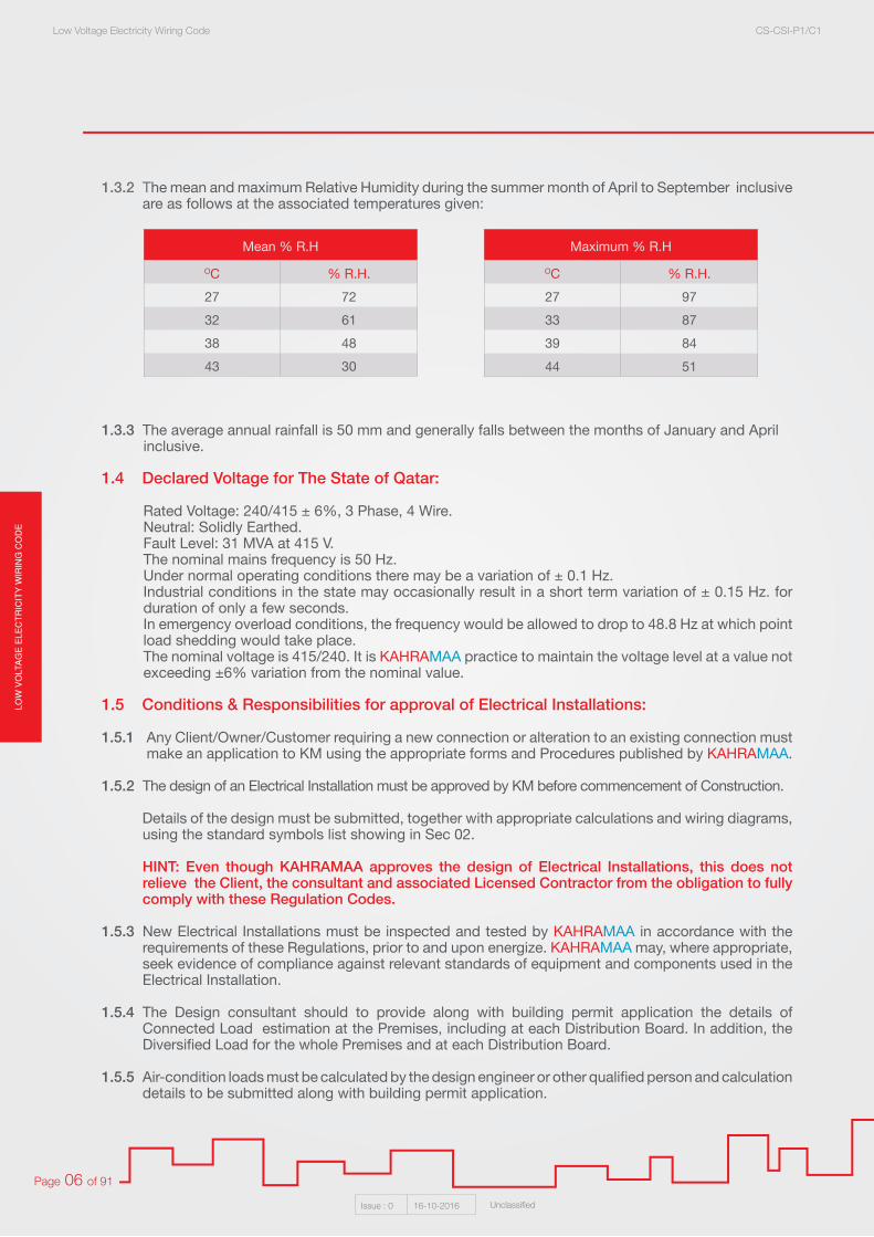
1.3.2 The mean and maximum Relative Humidity during the summer month of April to September inclusive are as follows at the associated temperatures given:
1.3.3 The average annual rainfall is 50 mm and generally falls between the months of January and April inclusive.
1.4 Declared Voltage for The State of Qatar:
Rated Voltage: 240/415 ± 6%, 3 Phase, 4 Wire. Neutral: Solidly Earthed. Fault Level: 31 MVA at 415 V. The nominal mains frequency is 50 Hz. Under normal operating conditions there may be a variation of ± 0.1 Hz. Industrial conditions in the state may occasionally result in a short term variation of ± 0.15 Hz. for duration of only a few seconds. In emergency overload conditions, the frequency would be allowed to drop to 48.8 Hz at which point load shedding would take place.The nominal voltage is 415/240. It is KAHRAMAA practice to maintain the voltage level at a value not exceeding ±6% variation from the nominal value.
1.5 Conditions & Responsibilities for approval of Electrical Installations:
1.5.1 Any Client/Owner/Customer requiring a new connection or alteration to an existing connection must make an application to KM using the appropriate forms and Procedures published by KAHRAMAA.
1.5.2 The design of an Electrical Installation must be approved by KM before commencement of Construction.
Details of the design must be submitted, together with appropriate calculations and wiring diagrams, using the standard symbols list showing in Sec 02.
HINT: Even though KAHRAMAA approves the design of Electrical Installations, this does not relieve the Client, the consultant and associated Licensed Contractor from the obligation to fully comply with these Regulation Codes.
1.5.3 New Electrical Installations must be inspected and tested by KAHRAMAA in accordance with the requirements of these Regulations, prior to and upon energize. KAHRAMAA may, where appropriate, seek evidence of compliance against relevant standards of equipment and components used in the Electrical Installation.
1.5.4 The Design consultant should to provide along with building permit application the details of Connected Load estimation at the Premises, including at each Distribution Board. In addition, the Diversified Load for the whole Premises and at each Distribution Board.
1.5.5 Air-condition loads must be calculated by the design engineer or other qualified person and calculation details to be submitted along with building permit application.
Mean % R.H
OC % R.H.
27 72
32 61
38 48
43 30
Maximum % R.H
OC % R.H.
27 97
33 87
39 84
44 51

LOW
VO
LTAG
E E
LEC
TR
ICIT
Y W
IRIN
G C
OD
ELow Voltage Electricity Wiring Code CS-CSI-P1/C1
Issue : 0 16-10-2016 Unclassified
Page 07 of 91
1.6 Extensions, alterations and repairs:
1.6.1 No extension or alteration to an Electrical Installation may be made without prior notification to KAHRAMAA and with prior approval.
1.6.2 All extensions or alterations to an existing Electrical Installation must comply with the requirements of these Regulations.
1.6.3 Work on any part of the Electrical Installation other than Final Circuits, including any Distribution Board and any items at the Electricity Intake, must be officially notified to KAHRAMAA prior to commencement of work.
1.6.4 Any proposed increase greater than 10% of the total Connected Load at a Premises, or greater than 10% of the Connected Load at any Distribution Board, must be approved by KAHRAMAA as per the procedures followed.
1.7 Licensed Contractors:
1.7.1 Work on Electrical Installations may only be carried out by Licensed Contractors who have been assessed and authorized by KAHRAMAA/CSD.
1.7.2 A list of Licensed Contractors shall be kept up-to-date by KAHRAMAA and provided upon requested.
1.7.3 The licensed electrical contractors shall comply the latest terms, rules and regulations issued by KAHRAMAA, for the internal electrical installations works in the State of Qatar.
1.7.4 Licensed low voltage electrical contractor to comply with the following license classification and requirements:
Class Permitted Electrical Loads (KW) Technical staff Requirement
1. Unlimited loads
(2) Electrical Eng. (A)
(1) Electrical Eng. (B)
(2) Electrical Supervisor(10) Electricians
2. 1000
(1) Electrical Eng. (A)
(1) Electrical Eng. (B)
(1) Electrical Supervisor(6) Electricians
3. 500
(1) Electrical Eng. (B)
(1) Electrical Eng. (C)
(1) Electrical Supervisor(3) Electricians
4. 250(1) Electrical Eng. (C)
(1) Electrical Supervisor(3) Electricians
5. 50(1) Electrical Supervisor(2) Electricians
Contractor’s License Classifications

LOW
VO
LTA
GE
ELE
CT
RIC
ITY
WIR
ING
CO
DE
Low Voltage Electricity Wiring Code CS-CSI-P1/C1
Issue : 0 16-10-2016 Unclassified
Page 08 of 91
Section 02: Definitions & Symbols
2.1 Voltage Classification:
2.2 Abbreviations:
Terminology Values
ELV- Extra low Voltage <25 V
LV- Low Voltage ≥25V - <1 KV
MV-Medium Voltage ≥1 KV - ≤ 33 KV
HV-High Voltage >33 KV - ≤ 132 KV
EHV-Extra High Voltage >132 KV
Abbreviation Name
CSD Customer Service Department
A Amps or Amperes
a.c. alternating current
d.c. direct current
a/c air-conditioning
BS British Standard
BS EN British Standard which has been published under the European Normalisation procedure
BSI British Standards Institute
ELCB Earth Leakage Circuit-Breaker
ELP Earth Leakage Protection
ELPS Earth Leakage Protected System
ELV Extra-Low Voltage
FDB Final Distribution Board
HP Horse-Power (= 0.746 kW)
HRC High Rupture Capacity (fuse)
HV High Voltage
MV Medium Voltage
LV Low Voltage
IEC International Electrotechnical Commission
In Nominal current rating or current setting of a Protective Device
kA kilo-Amps

LOW
VO
LTAG
E E
LEC
TR
ICIT
Y W
IRIN
G C
OD
ELow Voltage Electricity Wiring Code CS-CSI-P1/C1
Issue : 0 16-10-2016 Unclassified
Page 09 of 91
2.3 Definitions:
Accessory Any device, other than a lighting fitting, associated with the wiring and current using appliances of an installation, e.g. a switch, a fuse, a plug, a socket outlet, a lamp holder or a ceiling rose.
Adapter, Socket Outlet An accessory for insertion into a socket outlet and containing metal contacts, to which may be fitted one or more plugs for the purpose of connecting to the supply, portable lighting fitting or current using appliances.
Ambient Temperature (for Cable) The temperature of the surrounding medium under normal conditions, at a suitable in which cables are installed, or are to be installed, including the effect of any artificial heating used in the building by any local source of heat.
Apparatus Electrical apparatus, including all machines, equipment and fittings in which conductors are used or of which they form a part.
Appliance Any device which utilise electricity for a particular purpose, excluding lighting or an independent motor.
Bonded (As Applied to Items of Metal Work) Connected together electrically, not normally for the purpose of carrying current but so as to ensure a common potential.
m Meters
kV kilo-Volts
MCB Miniature Circuit-Breaker
MCCB Moulded Case Circuit-Breaker
MDB Main Distribution Board/Main low Voltage Switchgear
MICC Mineral Insulated Copper-Clad
ms milli-seconds
PELV Protective Extra-Low Voltage (see definitions)
PVC Poly-vinyl Chloride (insulation for LV cables)
r.m.s root-mean-square (value of voltage, current etc)
RCBO Residual Current Breaker (with) Overcurrent Protection
RCCB Residual Current Circuit-Breaker
RCD Residual Current Device
RLV Reduced Low Voltage
s seconds
S cross-sectional area (of conductors, mm²)
˚C degrees Celsius
MSB Main Switch Board
SMSB Sub Main Switch Board
SELV Separated Extra-Low Voltage
IN Service connection Application Number
MOC Method of connection
EN Electricity Number

LOW
VO
LTA
GE
ELE
CT
RIC
ITY
WIR
ING
CO
DE
Low Voltage Electricity Wiring Code CS-CSI-P1/C1
Issue : 0 16-10-2016 Unclassified
Page 10 of 91
Bunched Cables are said to be “bunched” when two or more are contained within a single conduit or trunking or, if not separated from each other.
Caravan Any structure designed or adapted for human habitation which is capable of being moved from one to another ( whether by being towed or being transported on a motor vehicle or trailer ) and any other motor vehicle so designed or adapted. The regulations apply where supply is provided by mains electricity or by generator at a voltage exceeding 50 Volts between poles.
Channel (for Cables) A groove cut or formed in part of a building and intended to receive on a more cables, the groove having removable or hinged covers to allow cables to be laid therein.
CB Circuit-Breaker: A mechanical device for making and breaking a circuit, both under normal conditions and under abnormal conditions, such as those of an overload or short circuit being broken automatically.
Circuit Conductor A current carrying conductor forming part a circuit or final sub circuit, but excluding the earth continuity conductor
Conductor (of Core or Cable) The conducting portion, consisting of a single wire or of a group of wires in contact with each other. For earthed concentric wiring, the term may also denote the metal sheath of a cable.
Connector A device intended for connection to a flexible core of flexible cable, which has protected current carrying contact tubes similar to those of a socket outlet.
Customer’s Installation: Wiring and apparatus situated upon the customer’s premises and controlled or installed by him, excluding any switchgear of the supply undertaking which the customer may be permitted to use.
Customer’s Terminals The point in the customer’s installation at which the incoming supply of energy is delivered to that installation.
Core (of Cable) The conductor with its insulation but not including any outer covering for mechanical or other protection.
Damp And Dust Proof Applied to apparatus and accessories to denote that the live and other component parts are protected by an enclosure or enclosures being so protected and or fitted as to prevent the ready ingress of dust and or moisture.
Damp Situation A situation in which moisture is either permanently present or intermittently present, to such an extent as to be likely to impair the effectiveness of an installation conforming to the requirements for ordinary situations.
Dead At earth potential and disconnected from any live system.
DB Distribution Board An assemblage of parts, including one or more circuit breakers, arranged for the distribution of electrical power.
Duct (for Cables) A closed passage way formed underground in a structure and intended to receive one or more cables which may be drawn in.
Earth Continuity Conductor The conductor, including any clamp, connecting to the customer’s earthing terminal or to the frame terminal of a voltage operated earth leakage circuit breaker or to each other, those parts of an installation which are required to be earthed. It may be the metal sheath and or armouring if a cable or the special earth continuity conductor of a cable or flexible cord incorporating such a conductor.

LOW
VO
LTAG
E E
LEC
TR
ICIT
Y W
IRIN
G C
OD
ELow Voltage Electricity Wiring Code CS-CSI-P1/C1
Issue : 0 16-10-2016 Unclassified
Page 11 of 91
Earth Electrode A metal rod or rods, a system of underground metal pipes or other conducting object, providing an effective connection with the general mass of the earth.
Earthed Effectively connected to the general mass of the earth.
Earthed Concentric Wiring A sheath return wiring system in which one or more insulated conductors carrying the line current are completely surrounded throughout their length by a conductor which acts as the earth continuity conductor.
Earthing Lead The final conductor by which the connection to the earth electrode or other means of earthing is made.
Electric Discharge Lamp An electric lamp comprising an hermetically sealed bulb or tube containing gas and or metal intended to be vaporised during operation and fitted with electrodes between which a discharge of electricity takes places, the useful light being emitted either by the discharge through the gas or vapour or by the fluorescence of a translucent coating which may be on the inner surface of the outer tube or bulb.
Electrode Boiler (or Electrode Water Heater) Apparatus for the electrical heating of water by the passage of an electric current between electrodes immersed in the water.
Excess Current Protection Close Excess current protection which will operate within Four Hours at 1.50 times the designed load current of the circuit which is protects.
Final Sub Circuit An outgoing circuit connected to a distribution board and intended to supply electrical energy to current using apparatus, either directly or through socket outlets or fused spur boxes.
Flameproof Applied to apparatus to denote that the containing case or other enclose withstand without injury any explosion of prescribed flammable gas that may occur within it under practical conditions of operation within the rating of the apparatus (and recognized overloads, if any, associated therewith) and will prevent the transmission of flame such as will ignite any prescribed flammable gas that may be present in the surrounding atmosphere.
Flammable A flammable material is one capable of being easily ignited.
Flood Lighting Flood lights are broad - beamed, high intensity artificial lights, typical application is to illuminate outdoor playing fields while an outdoor sports event is being held during low - light conditions.
Flexible Cord A flexible cable in which the cross sectional area of each conductor does not exceed 4 mm.
Fuse A device for opening a circuit by means of a fuse element designed to melt when an excessive current flows. It normally consists of a fuse base and fuse link. The fuse link may take the form of a cartridge or a carrier supporting a fuse element. For the purpose of these regulations the current rating of a fuse is a current, less than the minimum fuse current, stated by the maker as the current that the fuse and the fuse link with which it is fitted will carry continuously without deterioration, see BS 88-2 2007 (Specification Of Supplementary Requirements For Fuse - Links For Use In A.C. Electricity Supply Networks).
Fuse Element That part of a fuse which designed to melt and thus open a circuit.
Insulation Suitable non conducting material enclosing, surrounding or supporting a conductor.
LOW
VO
LTA
GE
ELE
CT
RIC
ITY
WIR
ING
CO
DE
Low Voltage Electricity Wiring Code CS-CSI-P1/C1
Issue : 0 16-10-2016 Unclassified
Page 12 of 91
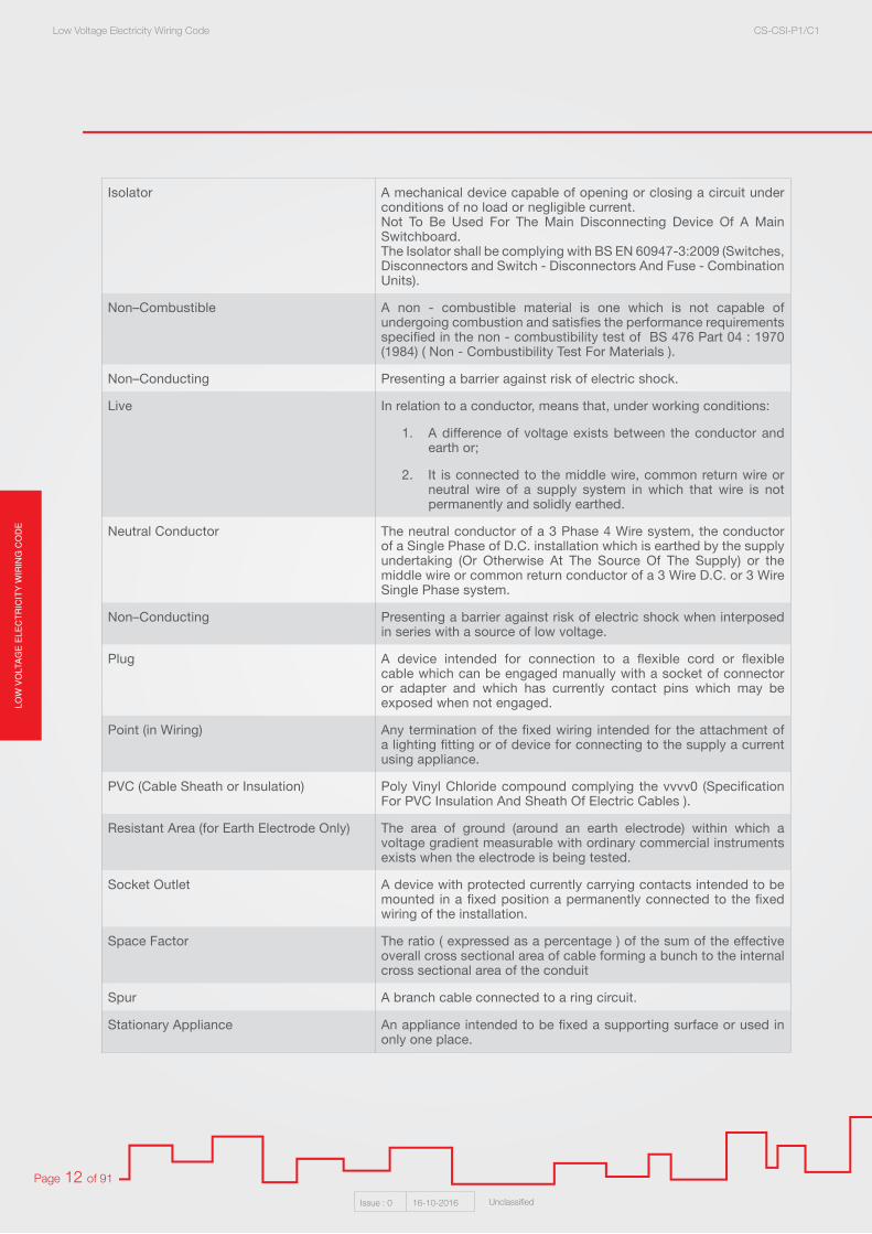
Isolator A mechanical device capable of opening or closing a circuit under conditions of no load or negligible current. Not To Be Used For The Main Disconnecting Device Of A Main Switchboard. The Isolator shall be complying with BS EN 60947-3:2009 (Switches, Disconnectors and Switch - Disconnectors And Fuse - Combination Units).
Non–Combustible A non - combustible material is one which is not capable of undergoing combustion and satisfies the performance requirements specified in the non - combustibility test of BS 476 Part 04 : 1970 (1984) ( Non - Combustibility Test For Materials ).
Non–Conducting Presenting a barrier against risk of electric shock.
Live In relation to a conductor, means that, under working conditions:
1. A difference of voltage exists between the conductor and earth or;
2. It is connected to the middle wire, common return wire or neutral wire of a supply system in which that wire is not permanently and solidly earthed.
Neutral Conductor The neutral conductor of a 3 Phase 4 Wire system, the conductor of a Single Phase of D.C. installation which is earthed by the supply undertaking (Or Otherwise At The Source Of The Supply) or the middle wire or common return conductor of a 3 Wire D.C. or 3 Wire Single Phase system.
Non–Conducting Presenting a barrier against risk of electric shock when interposed in series with a source of low voltage.
Plug A device intended for connection to a flexible cord or flexible cable which can be engaged manually with a socket of connector or adapter and which has currently contact pins which may be exposed when not engaged.
Point (in Wiring) Any termination of the fixed wiring intended for the attachment of a lighting fitting or of device for connecting to the supply a current using appliance.
PVC (Cable Sheath or Insulation) Poly Vinyl Chloride compound complying the vvvv0 (Specification For PVC Insulation And Sheath Of Electric Cables ).
Resistant Area (for Earth Electrode Only) The area of ground (around an earth electrode) within which a voltage gradient measurable with ordinary commercial instruments exists when the electrode is being tested.
Socket Outlet A device with protected currently carrying contacts intended to be mounted in a fixed position a permanently connected to the fixed wiring of the installation.
Space Factor The ratio ( expressed as a percentage ) of the sum of the effective overall cross sectional area of cable forming a bunch to the internal cross sectional area of the conduit
Spur A branch cable connected to a ring circuit.
Stationary Appliance An appliance intended to be fixed a supporting surface or used in only one place.
LOW
VO
LTAG
E E
LEC
TR
ICIT
Y W
IRIN
G C
OD
ELow Voltage Electricity Wiring Code CS-CSI-P1/C1
Issue : 0 16-10-2016 Unclassified
Page 13 of 91
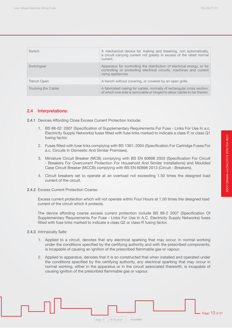
2.4 Interpretations:
2.4.1 Devices Affording Close Excess Current Protection Include:
1. BS 88-02: 2007 (Specification of Supplementary Requirements For Fuse - Links For Use In a.c. Electricity Supply Networks) fuses fitted with fuse links marked to indicate a class P, or class Q1 fusing factor.
2. Fuses fitted with fuse links complying with BS 1361: 2004 (Specification For Cartridge Fuses For a.c. Circuits In Domestic And Similar Premises).
3. Miniature Circuit Breaker (MCB) complying with BS EN 60898 2003 (Specification For Circuit - Breakers For Overcurrent Protection For Household And Similar Installations) and Moulded Case Circuit Breaker (MCCB) complying with BS EN 60898 2013 (Circuit - Breakers).
4. Circuit breakers set to operate at an overload not exceeding 1.50 times the designed load current of the circuit.
2.4.2 Excess Current Protection Coarse:
Excess current protection which will not operate within Four Hours at 1.50 times the designed load current of the circuit which it protects.
The device affording coarse excess current protection include BS 88-2 2007 (Specification Of Supplementary Requirements For Fuse - Links For Use In A.C. Electricity Supply Networks) fuses fitted with fuse links marked to indicate a class Q2 or class R fusing factor.
2.4.3 Intrinsically Safe:
1. Applied to a circuit, denotes that any electrical sparking that may occur, in normal working under the conditions specified by the certifying authority and with the prescribed components, is incapable of causing an ignition of the prescribed flammable gas or vapour.
2. Applied to apparatus, denotes that it is so constructed that when installed and operated under the conditions specified by the certifying authority, any electrical sparking that may occur in normal working, either in the apparatus or in the circuit associated therewith, is incapable of causing ignition of the prescribed flammable gas or vapour.
Switch A mechanical device for making and breaking, non automatically, a circuit carrying current not greatly in excess of the rated normal current.
Switchgear Apparatus for controlling the distribution of electrical energy, or for controlling or protecting electrical circuits, machines and current using appliances.
Trench Open A trench without covering, or covered by an open grille.
Trucking (for Cable) A fabricated casing for cables, normally of rectangular cross section, of which one side is removable or hinged to allow cables to lair therein.

LOW
VO
LTA
GE
ELE
CT
RIC
ITY
WIR
ING
CO
DE
Low Voltage Electricity Wiring Code CS-CSI-P1/C1
Issue : 0 16-10-2016 Unclassified
Page 14 of 91
2.5 Standard Electrical diagram symbols:
Symbol Description Symbol Description
Main Distribution Board (MDB) Three phase isolator
Sub Main Distribution Board (SMDB) Single phase isolator
Distribution Board (DB) Shaver socket to BS EN 61558-2-5
Air Circuit Breaker (ACB) Cooker control unit
Moulded Case Circuit Breake (MCCB) Tungsten light fitting - ceilling mounted
Miniature Circuit Breaker (MCB) Tungsten light fitting - wall mounted
Earth Leakage Protective Device (RCD) Fluorescent Light Fitting- ceilling mounted
Fuse Fluorescent light fitting- wall mounted
Link Light switch - 1 way
kWh meter (direct reading) Light switch - 2 way
kWh meter (ct operated) Light switch - intermediate way
Switched line (e.g. connecting all outlets controlled by one switch) Light switch - Pull cord operated
Circuit line (e.g. connecting all outlets on the same circuit) Light switch - key operated
13 A switched socket outlet Light switch - weather proof type
15 A switched socket outlet Exhaust fan
Switched fuse connection unit Ceiling mounted fan
Unswitched fuse connection unit Low level cooker outlet connection
Industrial socket-outlet Earth connection
20 A double pole switch with neon indicator
Note: Any additional wiring symbols may be as per BS EN 60617
CCU
W
x
M
M
LOW
VO
LTAG
E E
LEC
TR
ICIT
Y W
IRIN
G C
OD
ELow Voltage Electricity Wiring Code CS-CSI-P1/C1
Issue : 0 16-10-2016 Unclassified
Page 15 of 91
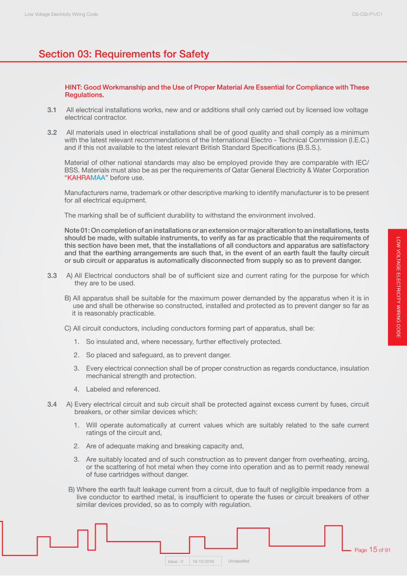
Section 03: Requirements for Safety
HINT: Good Workmanship and the Use of Proper Material Are Essential for Compliance with These Regulations.
3.1 All electrical installations works, new and or additions shall only carried out by licensed low voltage electrical contractor.
3.2 All materials used in electrical installations shall be of good quality and shall comply as a minimum with the latest relevant recommendations of the International Electro - Technical Commission (I.E.C.) and if this not available to the latest relevant British Standard Specifications (B.S.S.).
Material of other national standards may also be employed provide they are comparable with IEC/
BSS. Materials must also be as per the requirements of Qatar General Electricity & Water Corporation “KAHRAMAA” before use.
Manufacturers name, trademark or other descriptive marking to identify manufacturer is to be present for all electrical equipment.
The marking shall be of sufficient durability to withstand the environment involved.
Note 01: On completion of an installations or an extension or major alteration to an installations, tests should be made, with suitable instruments, to verify as far as practicable that the requirements of this section have been met, that the installations of all conductors and apparatus are satisfactory and that the earthing arrangements are such that, in the event of an earth fault the faulty circuit or sub circuit or apparatus is automatically disconnected from supply so as to prevent danger.
3.3 A) All Electrical conductors shall be of sufficient size and current rating for the purpose for which they are to be used.
B) All apparatus shall be suitable for the maximum power demanded by the apparatus when it is in use and shall be otherwise so constructed, installed and protected as to prevent danger so far as
it is reasonably practicable.
C) All circuit conductors, including conductors forming part of apparatus, shall be:
1. So insulated and, where necessary, further effectively protected.
2. So placed and safeguard, as to prevent danger.
3. Every electrical connection shall be of proper construction as regards conductance, insulation mechanical strength and protection.
4. Labeled and referenced.
3.4 A) Every electrical circuit and sub circuit shall be protected against excess current by fuses, circuit breakers, or other similar devices which:
1. Will operate automatically at current values which are suitably related to the safe current ratings of the circuit and,
2. Are of adequate making and breaking capacity and,
3. Are suitably located and of such construction as to prevent danger from overheating, arcing, or the scattering of hot metal when they come into operation and as to permit ready renewal of fuse cartridges without danger.
B) Where the earth fault leakage current from a circuit, due to fault of negligible impedance from a live conductor to earthed metal, is insufficient to operate the fuses or circuit breakers of other similar devices provided, so as to comply with regulation.

LOW
VO
LTA
GE
ELE
CT
RIC
ITY
WIR
ING
CO
DE
Low Voltage Electricity Wiring Code CS-CSI-P1/C1
Issue : 0 16-10-2016 Unclassified
Page 16 of 91
C) The circuit shall be protected against the persistence of earth leakage currents liable to cause danger by an earth leakage circuit breaker or equivalent device.
Note 02: Rewireable fuses are not permitted under any circumstances. Every single pole shall be inserted in the live conductor only. Any switch connected in the conductor connected with earth or neutral shall be a linked switch and shall be arranged to break also all the live conductors.
3.5 All one way switches both single and double pole, shall be mounted so that the dolly is up when the switch is in the “Off” position. This shall not be considered to be applicable to fireman’s switches.
3.6 Where metal work, other than current carrying conductors, is liable to become charged with electricity
1. The metal work shall be earthed in such a manner as will ensure immediate electrical discharge without danger of shock or fire.
2. Other adequate precautions shall be taken to prevent danger.
3.7 Effective means, suitably placed for ready operations, shall be provided so that all voltage may be cut off from every circuit and sub circuit and from all apparatus, as may be necessary to prevent danger.
3.8 Every electric motor shall be controlled by an efficient device for starting and stopping, such switch is to be readily operated and so placed as to prevent danger.
3.9 A) All apparatus and conductors exposed to weather, corrosive atmosphere, or other adverse condition, shall be so constructed or protected as may be necessary to prevent danger arising from such exposure.
B) Where a conductor or apparatus is, or is likely to be, exposed to flammable surroundings or an explosive atmosphere, it shall be protected by a flameproof enclosure or be otherwise so designed and constructed as to prevent danger.
3.10 Conductors and apparatus operating at voltage between conductors or to earth and exceeding 250 Volts shall either:
1. Be completely enclosed in earthed metal, which is electrically continuous and adequately protected against mechanical damage or
2. Be so constructed, installed and protected as to prevent danger as far as is reasonably practicable and to comply with the various sections of these regulations.
3.11 In a situation which may be normally wet or damp, where electrical apparatus is present and might give rise to danger, and where there are substantial exposed metal parts of other services ( such as gas and water pipes, sinks, and baths ), the earth continuity conductor of the electrical installation shall be effectively connected, electrically and mechanically, to all such metal parts and to any exposed metal work of the electrical apparatus.
3.12 Electrical equipment shall be firmly secured to the surface on which it is mounted. Wooden plugs driven into holes in masonry, concrete or plaster shall not be used. Electrical equipment shall be installed so that wall or other obstructions do not prevent free circulation of cooling air.
LOW
VO
LTAG
E E
LEC
TR
ICIT
Y W
IRIN
G C
OD
ELow Voltage Electricity Wiring Code CS-CSI-P1/C1
Issue : 0 16-10-2016 Unclassified
Page 17 of 91
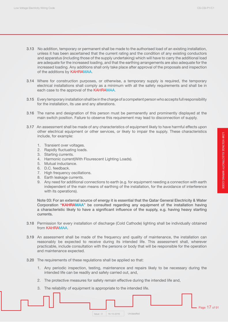
3.13 No addition, temporary or permanent shall be made to the authorised load of an existing installation, unless it has been ascertained that the current rating and the condition of any existing conductors and apparatus (including those of the supply undertaking) which will have to carry the additional load are adequate for the increased loading, and that the earthing arrangements are also adequate for the increased loading. Any additions shall only take place after approval of the proposals and inspection of the additions by KAHRAMAA.
3.14 Where for construction purposes, or otherwise, a temporary supply is required, the temporary electrical installations shall comply as a minimum with all the safety requirements and shall be in each case to the approval of the KAHRAMAA.
3.15 Every temporary installation shall be in the charge of a competent person who accepts full responsibility for the installation, its use and any alterations.
3.16 The name and designation of this person must be permanently and prominently displayed at the main switch position. Failure to observe this requirement may lead to disconnection of supply.
3.17 An assessment shall be made of any characteristics of equipment likely to have harmful effects upon other electrical equipment or other services, or likely to impair the supply. These characteristics include, for example:
1. Transient over voltages. 2. Rapidly fluctuating loads. 3. Starting currents. 4. Harmonic current(With Flourescent Lighting Loads).5. Mutual inductance. 6. D.C. feedback. 7. High frequency oscillations. 8. Earth leakage currents. 9. Any need for additional connections to earth (e.g. for equipment needing a connection with earth
independent of the main means of earthing of the installation, for the avoidance of interference with its operations).
Note 03: For an external source of energy it is essential that the Qatar General Electricity & Water Corporation “KAHRAMAA” be consulted regarding any equipment of the installation having a characteristic likely to have a significant influence of the supply, e.g. having heavy starting currents.
3.18 Permission for every installation of discharge (Cold Cathode) lighting shall be individually obtained from KAHRAMAA.
3.19 An assessment shall be made of the frequency and quality of maintenance, the installation can reasonably be expected to receive during its intended life. This assessment shall, wherever practicable, include consultation with the persons or body that will be responsible for the operation and maintenance expected.
3.20 The requirements of these regulations shall be applied so that:
1. Any periodic inspection, testing, maintenance and repairs likely to be necessary during the intended life can be readily and safely carried out, and,
2. The protective measures for safety remain effective during the intended life and,
3. The reliability of equipment is appropriate to the intended life.

LOW
VO
LTA
GE
ELE
CT
RIC
ITY
WIR
ING
CO
DE
Low Voltage Electricity Wiring Code CS-CSI-P1/C1
Issue : 0 16-10-2016 Unclassified
Page 18 of 91
Section 04: Main Low Voltage Services Arrangements and Distribution Boards
4.1 Main Low Voltage Switch-rooms:
4.1.1 All Main Low Voltage (LV) main switch-rooms shall be air conditioned by means of extending the central air conditioning duct work system supplying the complete building or wall mounted self contained air conditioning units installed within the L.V switch-room.
The air conditioning shall be sized to limit the room temperature to a maximum of 35°C under maximum load conditions.
Where individual room A/C’s are installed then maintenance of the units must be carried out at regular intervals and to ensure maintaining the required room temperature and for possibility of any a/c unit failure in operation, should use one of the following techniques:
i. Install duty and stand by unit(s) controlled by MCC panel with failure in operation alarm.
ii. For unique MDB rooms should install temperature sensor with audible and light alarm to detect and produce an alarm in case of indoor temperature raise than 40°C or to send alarm to the BMS if applicable.
The switch rooms must be insulated as per KM energy conservation insulation specifications.
4.1.2 Services associated with air conditioning, water and drainage shall not be allowed to pass L.V switch-rooms.
4.1.3 The design and layout of the Main Low Voltage rooms must be approved by Qatar General Electricity & Water Corporation “KAHRAMAA” before construction of the building. Due consideration must be made of the dimensions of switchgear to be installed when the design is carried out. It must be appreciated that dimensions for similar equipment vary considerably.
If clearances are not sufficient when the switchgear is installed into the building, supply will not be made, till all clearance requirements are met.
Design consultant is responsible for proper estimation of the MDB(s) size dimensions and separate sketch indicating the cubical panel(s) and any associated Capacitor banks to be provided during building permit approval associated with the room dimensions and required clearance.
4.1.4 Main Low Voltage Switchgear(s) room Clearances:
• Minimum 1.5 m front clearance.• Minimum 0.75 m rear clearance.• Minimum 0.75 m side to wall clearance.• Minimum 0.75 m side to another Cubical/PFC panel clearance.• Minimum of 0.75m clearance for ventilation around capacitor bank(s).

LOW
VO
LTAG
E E
LEC
TR
ICIT
Y W
IRIN
G C
OD
ELow Voltage Electricity Wiring Code CS-CSI-P1/C1
Issue : 0 16-10-2016 Unclassified
Page 19 of 91
4.1.5 Design Considerations:
• Access for personnel (normal and emergency)• Access for equipment (installation, operation and maintenance)• Regulatory compliance and approvals• Cable containment and entries• Earthing and grounding • Water sealing (if below ground)• Air conditioning, lighting & small power.• Fire detection, alarm and suppression• Any holes shall be sealed by suitable materials.
4.2 Main L.V Switchgear (MDB) / M.L.V.P.
4.2.1 Any Main low voltage Distribution Board-MDB / M.L.V.P. shall be of cubicle construction.
4.2.2 All MDB details shall be submitted to the Qatar General Electricity & Water Corporation “KAHRAMAA”/ Customer Service Dept. for prior approval before the manufacturing.
4.2.3 Each manufacture of cubicle panel shall supply all relevant authorized test certificates regarding the fault level capabilities of the type of proposed panel as per Main L.V Switchgear submittal checklist.
4.2.4 These test certificates must be provided by a certified independent test authority and not carried out
by the individual manufacturer.
4.2.5 Protection curves showing the time/current tripping characteristics of a Main Switch Fuses, M.C.C.B. and A.C.B. shall be submitted to the Qatar General Electricity & Water Corporation “KAHRAMAA” together with the manufacturer’s working drawings.
4.2.6 Manufacturer submittal should include Main L.V Switchgear (MDB) room layout as per physical dimensions and site survey showing the location, clearance of the cubical panel(s), cables/Bus Ducts routing, capacitor banks and any installed equipments or panels inside the room in coordination with supervision consultant/Electrical contractor.

LOW
VO
LTA
GE
ELE
CT
RIC
ITY
WIR
ING
CO
DE
Low Voltage Electricity Wiring Code CS-CSI-P1/C1
Issue : 0 16-10-2016 Unclassified
Page 20 of 91
Form 3B, Type 2 Panel
PANEL SIZE: CABLE ENTRY:
TOTAL HEIGHT: 2000mm TRANSFORMER INCOMING: TOP BUSDUCT 2500A
TOTAL DEPTH: 1000mm GENERATOR INCOMING: BOTTOM CABLES
TOTAL WIDTH: 4200mm OUTGOING: BOTTOM CABLES
FRONT VIEWGuide for Cubical panel front view with dimensions
DE
PTH
: 100
0mm
TOP VIEW
BOTTOM VIEWExample of Cubical panel Top & Bottom view with dimensions

LOW
VO
LTAG
E E
LEC
TR
ICIT
Y W
IRIN
G C
OD
ELow Voltage Electricity Wiring Code CS-CSI-P1/C1
Issue : 0 16-10-2016 Unclassified
Page 21 of 91
4.2.7 Minimum form of separation for MDB is Form 3B Type 2.
Main criteria Sub-criteria Form Type of construction
No separation Form 1
Separation of busbars from the functional units
Terminals for external conductors not separated from busbars
Form 2a
Terminals for external conductors separated from busbars
Form 2b Type 1 Busbar separation is achieved by insulated covering, e.g. sleeving, wrapping or coatings¹)
Type 2 Busbar separation is by metallic or non-metallic rigid barriers or partions
Separation of busbars from the functional units and separation of all functional units from one another
Terminals for external conductors not separated from busbars
Form 3a
Separation of the terminals for external conductors from the functional units, but not from each other
Terminals for external conductors separated from busbars
Form 3b Type 1 Busbar separation is achieved by insulated covering, e.g. sleeving, wrapping or coatings¹)
Type 2 Busbar separation is by metallic or non-metallic rigid barriers or partitions
Separation of busbars from the functional units and separation of all functional units from one another, including the terminals for external conductors which are an integral part of the functional unit.
Terminals for external conductors in the same compartment as the associated functional unit
Form 4a Type 1 Busbar separation is achieved by insulated covering, e.g. sleeving, wrapping or coatings¹) Cables may be glanded elsewhere
Type 2 Busbar separation is by metallic or non-metallic rigid barriers or partitions Cables may be glanded elsewhere
Type 3 Busbar separation is by metallic or non-metallic rigid barriers or partitionsThe termination for each functional unit has its own integral glanding facility
Terminals for external conductors not in the same compartment as the associated functional unit, but in individual, separate, enclosed protected spaces or compartments
Form 4b Type 4 Busbar separation is achieved by insulated covering, e.g. sleeving, wrapping or coatings¹) cables may be glanded elsewhere
Type 5 Busbar separation is by metallic or non-metallic rigid barriers or partitionsTerminals may be separated by insulated coverings¹) and glanded in common cabling chamber(s)
Type 6 All separation requirements are by metallic or non-metallic rigid barries or partitionsCables are glanded in common cabling chamber(s)
Type 7 All separation requirements are by metallic or non-metallic rigid barries or partitionsThe termination for each functional unit has its own integral glanding facility
Forms of separation as per BS EN 61439-2:2011

LOW
VO
LTA
GE
ELE
CT
RIC
ITY
WIR
ING
CO
DE
Low Voltage Electricity Wiring Code CS-CSI-P1/C1
Issue : 0 16-10-2016 Unclassified
Page 22 of 91
4.3 KAHRAMAA Incoming Supply Cable:
4.3.1 Where the incoming supply cables are laid in a trench to the Main L.V Switchgear then that trench shall be used only for those cables.
4.3.2 In any installation, the main incoming supply cables to the Main L.V Switchgear shall be totally segregated from any other customer’s cables.
4.3.3 Suitable cable glands shall be provided on cubicle Main L.V Switchgear for the support of the incoming supply cable. These cable glands shall be located and shall be fixed to a metal plate of non ferrous material (i.e. brass, etc).
4.3.4 Where the MDB is supplied directly from the secondary of the Qatar General Electricity & Water Corporation “KAHRAMAA” transformer and no cut out is installed, the maximum length permitted for these cables from transformer to the main switch of the customer’s main L.V. switchboard shall be 10 meters.
4.4 Switchboard Panels Materials:
Switchboard panels shall be constructed wholly of durable, non flammable, non hygroscopic, vermin proof material and all insulators shall be of permanently highly electric strength and insulation resistance.
4.4.1 Arrangement of Apparatus on Main Switchboards: All apparatus shall be so placed on a switchboard to ensure ample room for its safe and effective operation and handling.
Form 3Separation of busbars from all functional units
+Separation of all functional units from one another
+Separation of terminal for external conductors and external conductors from the functional units, but not from the
terminals of other functional units.
Form 3 as per BS EN 61439-2:2011
Form 3a:Terminals not separated from busbars
IEC 1715/11
Form 3b:Terminals and external conductors separated from
busbarsIEC 1716/11

LOW
VO
LTAG
E E
LEC
TR
ICIT
Y W
IRIN
G C
OD
ELow Voltage Electricity Wiring Code CS-CSI-P1/C1
Issue : 0 16-10-2016 Unclassified
Page 23 of 91
4.5 Labels:
Every cubicle panel shall bear a permanently affixed label, marked durably and fitted on the incoming main switch panel giving the following information:
1. Manufacturers name and address.
2. Sufficient indication to enable the panel to be identified for purpose of obtaining information, etc. from the manufacturer.
3. Rated operating voltage, current and frequency.
4. Short circuit rating.
5. Class of switchboard in accordance with BS EN 60439 Part 01: 1999 (Type - Tested and Partially Type - Tested Assemblies). Minimum form of separation: Form 3B Type 2.
6. IN, MOC, EN & TX number.
7. Labels for the rear outgoing circuit breakers connection. 4.6 Main Switches:
4.6.1 The main switch or switches of every installation shall be marked as such and shall be identifiable from other switchgear by grouping, colouring, or other suitable means, such as to render it (or them) easily located in an emergency.
Where there is more than one main switch in any building, each shall be marked to indicate which installation or section of the installation it controls.
In a cubicle MDB each main controlling switch shall be located in its own section, completely segregated from all other parts of the switchboard with front access for operation. Where a MDB is connected directly to the Low voltage winding of a transformer without any intermediate cut out then the main controlling switch (or switches) shall be the totally withdrawable Air Circuit Breaker (ACB) Triple (TP) Pole A. C. B.
The incomer A.C.B. shall be provided with seal device to seal the control unit of the A.C.B.
4.7 Discrimination, selectivity and co-ordination:
4.7.1 Discrimination between all upstream and downstream protective devices may be required for convenience or continuity of supply to essential equipment, but this may make the electrical system over-designed (much too large for its designed use) and thus carry a cost burden.
4.7.2 To provide a cost-effective and efficient design it helps if the main incoming supply point is close to the load centre of the installation, and hence pre-design discussions with the electricity distributor should be started at an early stage.
Note: Section 536 of BS 7671: 2008 details requirements for protective device Co-ordination.
4.7.3 An overall ‘system’ design view has to be taken on discrimination and co-ordination as otherwise this can lead to uneconomic schemes. For some installations, depending upon the number of protective devices between Final circuit and incomer protection, it may be an expensive luxury to design for full Discrimination.

LOW
VO
LTA
GE
ELE
CT
RIC
ITY
WIR
ING
CO
DE
Low Voltage Electricity Wiring Code CS-CSI-P1/C1
Issue : 0 16-10-2016 Unclassified
Page 24 of 91
4.7.4 Below figure illustrates this point; a final circuit distribution board has a socket outlet protected by a 32 A circuit breaker.
As can be seen, by using a 2:1 discrimination rule to achieve full discrimination, a 2000 A main protective device is required and we have not considered any loads! This demonstrates that, for many installations, whole system discrimination is not Justified unless there are life-critical constraints.
4.8 Metering:
Main Meter Spare Provision shall be made in cubicle main switchboards for the installation of the Qatar General Electricity & Water Corporation “KAHRAMAA” metering equipment located in separate cubicle above or below the main switch even there are land lords or individual meters.
Current Transformers CT’s (Class 1 or 0.5) (or Approved Equivalent) metering type shall be installed on all types of main switchboards where the load dictates metering by means of current transformers.
CT’s shall be located on the main bus bars immediately after the main incoming switch where the complete installation is to be metered at source.
Otherwise, where metering is carried out remotely, as in residential accommodation, the landlords located on the bus-bars immediately before the landlord’s distribution sections.
Removable links 250 mm long shall be provided in the main bus-bar of each phase to enable easy maintenance and replacement of current transformers.
Where metering CT’s are to be installed in a cubicle main switchboard, they shall be supplied and fitted by the panel manufacturer to comply with Qatar General Electricity & Water Corporation “KAHRAMAA” requirements. The following standard sizes of CT’s are used:
The Regulation states that discrimination should be considered to prevent danger and where required for proper functioning of the installation.
LOW
VO
LTAG
E E
LEC
TR
ICIT
Y W
IRIN
G C
OD
ELow Voltage Electricity Wiring Code CS-CSI-P1/C1
Issue : 0 16-10-2016 Unclassified
Page 25 of 91
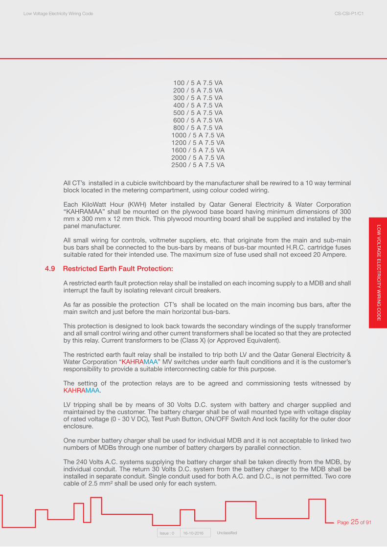
All CT’s installed in a cubicle switchboard by the manufacturer shall be rewired to a 10 way terminal block located in the metering compartment, using colour coded wiring.
Each KiloWatt Hour (KWH) Meter installed by Qatar General Electricity & Water Corporation “KAHRAMAA” shall be mounted on the plywood base board having minimum dimensions of 300 mm x 300 mm x 12 mm thick. This plywood mounting board shall be supplied and installed by the panel manufacturer.
All small wiring for controls, voltmeter suppliers, etc. that originate from the main and sub-main bus bars shall be connected to the bus-bars by means of bus-bar mounted H.R.C. cartridge fuses suitable rated for their intended use. The maximum size of fuse used shall not exceed 20 Ampere.
4.9 Restricted Earth Fault Protection:
A restricted earth fault protection relay shall be installed on each incoming supply to a MDB and shall interrupt the fault by isolating relevant circuit breakers.
As far as possible the protection CT’s shall be located on the main incoming bus bars, after the main switch and just before the main horizontal bus-bars.
This protection is designed to look back towards the secondary windings of the supply transformer and all small control wiring and other current transformers shall be located so that they are protected by this relay. Current transformers to be (Class X) (or Approved Equivalent).
The restricted earth fault relay shall be installed to trip both LV and the Qatar General Electricity & Water Corporation “KAHRAMAA” MV switches under earth fault conditions and it is the customer’s responsibility to provide a suitable interconnecting cable for this purpose.
The setting of the protection relays are to be agreed and commissioning tests witnessed by KAHRAMAA.
LV tripping shall be by means of 30 Volts D.C. system with battery and charger supplied and maintained by the customer. The battery charger shall be of wall mounted type with voltage display of rated voltage (0 - 30 V DC), Test Push Button, ON/OFF Switch And lock facility for the outer door enclosure.
One number battery charger shall be used for individual MDB and it is not acceptable to linked two numbers of MDBs through one number of battery chargers by parallel connection.
The 240 Volts A.C. systems supplying the battery charger shall be taken directly from the MDB, by individual conduit. The return 30 Volts D.C. system from the battery charger to the MDB shall be installed in separate conduit. Single conduit used for both A.C. and D.C., is not permitted. Two core cable of 2.5 mm² shall be used only for each system.
100 / 5 A 7.5 VA200 / 5 A 7.5 VA300 / 5 A 7.5 VA400 / 5 A 7.5 VA500 / 5 A 7.5 VA600 / 5 A 7.5 VA800 / 5 A 7.5 VA
1000 / 5 A 7.5 VA1200 / 5 A 7.5 VA1600 / 5 A 7.5 VA2000 / 5 A 7.5 VA2500 / 5 A 7.5 VA
LOW
VO
LTA
GE
ELE
CT
RIC
ITY
WIR
ING
CO
DE
Low Voltage Electricity Wiring Code CS-CSI-P1/C1
Issue : 0 16-10-2016 Unclassified
Page 26 of 91
4.10 Sealing of Apparatus:
All apparatus, main switches, bus bars, sub main switches, rising main distribution systems installed on the supply side of any Qatar General Electricity & Water Corporation “KAHRAMAA” Meter shall have provision for sealing that apparatus by the KAHRAMAA. The removable lid section of rising main bus bars trunking shall have provision for sealing through the entire route length.
4.11 Bus-Bars:
All bus bars in a cubicle switch panel shall be rigidly supported throughout their route length and marked with their phase colour for identification. In a cubicle panel the main bus-bars shall be located in their own section, completely segregated from all other parts of the switchboard, with either front or rear access. All bus bars shall be of rectangular cross section and of tinned copper. Bus bars may be bare or shrouded with a continuous extruded sleeve marked with phase colours. In no circumstances will bus-bars wrapped with any type of tape be accepted.
4.12 Neutral and Earth Bar:
All cubicle main switchboards shall be complete with a separate neutral bar running the full length of the panel. The current carrying capacity of this neutral bar shall not be less than of the Qatar General Electricity & Water Corporation “KAHRAMAA” incoming supply conductor and shall be of rectangular cross section, hard drawn tinned copper.
All cubicle main switchboards shall be complete with a separate earth bar running the full length of the panel. The minimum size of this earth bar shall be 300 mm² hard tinned copper.
A removable earth to neutral bar link shall be installed in all switchboard and the minimum size of this bar shall be 300 mm² and of rectangular cross section. The link shall be fitted between the earth bar and the neutral conductor, leaving sufficient space for mounting of a Restricted Earth Fault Protection Neutral Current Transformer, between the point attachment of link and the termination.
Under no circumstances will a common earth/neutral bar be accepted. Earth bars, neutral bars and links shall be so located and mounted that access there to is not obstructed by the structure or wiring of the switchboard and so that all outgoing neutral and earth conductors can be readily and safely connected and disconnected without moving other cables or disconnecting supply to the switchboard.
4.13 Clearance from Bare Conductors and Live Parts:
All bar conductors and bar live parts of a switchboard shall be rigidly fixed in such a manner that a clearance of at least 20 mm is maintained between such conductors or parts of opposite polarity or phase and between such conductors or parts and any material other than insulating material.
The use of fiberboard type insulating material to allow clearance to be reduced below 20 mm will not be permitted.
4.14 Links:
Links shall be marked to indicate whether they are live or neutral.

LOW
VO
LTAG
E E
LEC
TR
ICIT
Y W
IRIN
G C
OD
ELow Voltage Electricity Wiring Code CS-CSI-P1/C1
Issue : 0 16-10-2016 Unclassified
Page 27 of 91
4.15 Cable Interconnections:
Where P.V.C. insulated cables are used for the interconnection of switchboards, these shall be terminated at the bus-bars by means of bolt fixing, crimp or soldered type cable lugs.
4.16 Main and Sub Main Switch Fuses:
4.16.1 On main switchboards the interconnections between the main bus bars and the outgoing main switch shall be of bus-bar type only.
4.16.2 Where switch-fuses are to be installed with KM prior approval for either the main or sub main circuits on any switchboard, these units shall be designed for fast make and break contacts.
4.16.3 This shall be achieved by means of mechanical spring arrangements where a prescribed torque must
be exerted before the switch makes or breaks its contact. For every fuse and circuit breaker there shall be provided on or adjacent to it, an indication of its intended nominal current as appropriate to the circuit it protects.
4.16.4 Labels, or other suitable means of identification, shall be provided to indicate the purpose of switchgear and control gear. Such labels are to be secured by screws. Where lids or doors in the switchgear enclosure can be opened without the use of a tool or key, all live conductive parts which are accessible if the lid or door is open shall be behind an insulating barrier which prevents persons from coming into contact with those parts, this insulating barrier shall provide a degree of protection of at least IP 2X and be removable only by use of a tool.
HINT: Miniature Circuit Breaker (MCB) distribution boards shall not be installed for main or sub main cable distribution, neither shall miniature circuit breakers be installed for any purpose as part of a cubicle panel nor shall rewireable fuses be permitted.
Figure 4.15
LOW
VO
LTA
GE
ELE
CT
RIC
ITY
WIR
ING
CO
DE
Low Voltage Electricity Wiring Code CS-CSI-P1/C1
Issue : 0 16-10-2016 Unclassified
Page 28 of 91
4.17 Fault Levels:
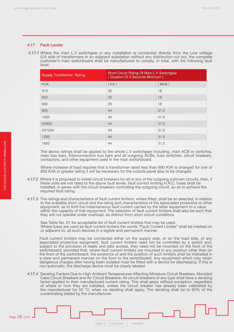
4.17.1 Where the main L.V switchgear in any installation is connected directly from the Low voltage (LV) side of transformers in an adjacent substation without any distribution cut out, the complete customer’s main switchboard shall be manufactured to comply, in total, with the following fault level:
The above ratings shall be applied to the whole L.V switchgear including, main ACB or switches, main bus bars, Interconnection bus bars and all outgoing ACBs, fuse switches, circuit breakers, contactors, and other equipment used in the main switchboard.
Where increase of load requires that a transformer rated less than 800 KVA is changed for one of 800 KVA or greater rating it will be necessary for the cubicle panel also to be changed.
4.17.2 Where it is proposed to install circuit breakers for all or any of the outgoing submain circuits, then, if these units are not rated to the above fault levels, fault current limiting H.R.C. fuses shall be installed, in series with the circuit breakers controlling the outgoing circuit, so as to achieve the required fault rating. 4.17.3 The ratings and characteristics of fault current limiters, where fitted, shall be so selected, in relation to the available short circuit and the rating and characteristics of the associated protective or other equipment, as to limit the instantaneous fault current carried by the latter equipment to a value within the capacity of that equipment. The selection of fault current limiters shall also be such that they will not operate under overload, as distinct from short circuit conditions.
See Table No. 01 for acceptable list of fault current limiters that may be used. Where fuses are used as fault current limiters the words “Fault Current Limiter” shall be marked on or adjacent to, all such devices in a legible and permanent manner.
Fault current limiters may be connected either on the supply side, or on the load side, of any associated protective equipment, fault current limiters need not be controlled by a switch and, subject to the provision of ready and safe access, they need not be mounted on the front of the switchboard; provided that, where fault current limiters are mounted in any position other than on the front of the switchboard, the existence of and the position of such limiters shall be indicated in a clear and permanent manner on the front to the switchboard. Any equipment which may retain dangerous charges after having been isolated must be fitted with a device for discharging. If this is non automatic, the discharge device must be clearly labeled.
4.17.4 Derating Factors Due to High Ambient Temperatures Affecting Miniature Circuit Breakers, Moulded Case Circuit Breakers and Air Circuit Breakers: All circuit breakers of any type shall have a derating factor applied to their manufactured current rating. This shall apply without exception, regardless of where or how they are installed, unless the circuit breaker has already been calibrated by the manufacturer for 50 °C, when no derating shall apply. The derating shall be to 80% of the currentrating stated by the manufacturer.
Supply Transformer Rating Short Circuit Rating Of Main L.V Switchgear( Duration Of 3 Seconds Minimum )
KVA ( KA ) ( MVA )
315 25 18
500 25 18
630 25 18
800 44 31.5
1000 44 31.5
2X800 44 31.5
2X1000 44 31.5
1250 44 31.5
1600 44 31.5
LOW
VO
LTAG
E E
LEC
TR
ICIT
Y W
IRIN
G C
OD
ELow Voltage Electricity Wiring Code CS-CSI-P1/C1
Issue : 0 16-10-2016 Unclassified
Page 29 of 91
4.17.5 Direct connection with the L.V switchgear: Only items directly associated with the provision of supply and direct control of sub circuits shall be permitted on a cubicle switchboard. These items shall include Qatar General Electricity & Water Corporation “KAHRAMAA” and generator main supply circuit breakers and changeover equipment, bus bars, links, meters and associated wiring, protection devices, outgoing switch-fuses or circuit breakers and power factor correction equipment.
4.17.6 The inclusion, within the cubicle panel construction, of switchgear operating, and indicating devices operated by items remote from the switchboard, where the circuit from the cubicle panel supplying these items remains live, regardless of the operation of the aforementioned switchgear and indications, will not be permitted. Any such equipment must be installed in a purpose made panel, which is physically separate from the cubicle panel.
Every switchboard shall be so arranged that safe access may be readily obtained for the purpose of removing, or replacing any conductor or piece of equipment forming a portion of the switchboard.
4.17.7 Where a switchboard is of such design that persons must enter the space behind the switchboard for the aforementioned purposes, provisions shall be made for ready and safe access to and exit from such space. The access shall not be less than 750 mm wide and 2000 mm high.
4.17.8 Where a switchboard incorporates rack out switchgear, doors or hinged panels at the front, there shall be a clearance of not less than 750 mm between any wall or immovable structure and the switchgear, doors, or hinged panels when in the racked out or open position.
4.17.9 For switchboard completely enclosed in a metal cabinet, or cubicle fitted with doors for the purposes of access, as required above, or cubicle switchboard shall be spaced at such a distance from the wall or immovable structure that ready access is available in front of the doors and be such that the doors may be fully opened. The doors shall be so arranged that when opened in any position, the minimum clearance between the door and the wall or immovable structure shall be 900 mm where the length of the switchboard does not exceed 4 meters.
4.17.10 Where a switchboard of this type is more than 4 meters in length the minimum space behind the switchboard shall be 1.20 meters with the largest door in the open position. Access shall be from both ends of the switchboard.
Where switchboard are provided with unhinged removable metal panels for the purpose of access as required above, such panels shall be provided with means of support, such as studs, or not less than two fixed pins or other suitable means, to retain the panels in position after the removal of fixing screws or bolts, etc. Where the area of a panel excess 0.75 m² handles or other suitable devices shall be provided to facilitate the above paragraph.
4.18 Hinged Panels:
Hinged switchboard panels, metal switchboard surrounds or enclosures shall be so constructed that the panel and the equipment mounted thereon will be adequately supported without undue distortion when the panel is in any position. For hinged panels, the hinging may be on the vertical edge provided that the width of the panel is not greater than 1½ times its height. Switchboards complying with this clause may be grouped together provided that the removal or hinging of a panel shall not be relied upon to give access to any other panel.
4.19 Access to Passageways:
Unless the switchboard is located in a switch room, to which only authorised persons have access, the space behind the switchboard shall be enclosed by a substantial wall or screen at least as high as the switchboard panel, and access to this space, as required above, shall be provided by lockable doors, arranged to open outwards and shall be capable of being opened from within without the use of a key.

LOW
VO
LTA
GE
ELE
CT
RIC
ITY
WIR
ING
CO
DE
Low Voltage Electricity Wiring Code CS-CSI-P1/C1
Issue : 0 16-10-2016 Unclassified
Page 30 of 91
4.19.1 All clearances given in this section are to be measured with all windows and doors in the closed position.
4.20 Alterations or Replacement of Switchgears:
If, in the opinion of the inspecting authority of the Qatar General Electricity & Water Corporation “KAHRAMAA” the apparatus comprising the switchboard or the layout and arrangement of the switchboard does not provide for the safe and effective control of the circuits and apparatus to be connected thereto, or supplied there from, it shall be replaced by a switchboard complying with the requirements of these regulations or if so required, it shall be reconstructed and rearranged so as to provide in accordance with the requirements of these regulations for the, safe and effective control of the circuits and apparatus. The costs of such alterations or replacement will not be the responsibility of KAHRAMAA.
4.21 Method of connection from KAHRAMAA Networks Check Planning Guidlines
4.21.1 Up to 200 Ampere Capacity:Service to general residential, small commercial and small industrial premises shall be provided to an approved design of electrical service cabinet at the boundary of the property concerned. Supply will be made available by this method to service capacity of approximately 200 Ampere and will normally be used for single occupier premises only.
Electrical service cabinet will normally be mounted in a wall facing a street, and as close as possible to the LV main which will supply it. Qatar General Electricity & Water Corporation “KAHRAMAA” therefore reserves the right to determine the location of the electrical service cabinet. See Sketch Nos. (12), (13) and (14).
Where supply is to be provided by KAHRAMAA to the customer at a mounted electrical service cabinet. The customer shall responsible for provision, of a suitable cable to provide connection between the electrical service cabinet and the main switchboard within the building.
The cable is to be installed within a 100 mm Ø duct which will have, at the electrical service cabinet and main switchboard, an easy bend. The duct shall be installed in accordance with KAHRAMAA regulations and a correctly sized earth wire must be installed with the cable.
Size of cable differing from these noted above may be used with the prior agreement of Qatar General Electricity & Water Corporation “KAHRAMAA”.
The minimum fault level for any supply position connected by means of a KAHRAMAA cut out shall be 12 KA (8.6 MVA) for a duration of 1 second. See also regulation 4.18.1. See Appendix No. 03 for electrical service cabinet specification.
4.21.2 Above 200 Ampere Capacity:
Location of Intake Position: Switchboards shall be installed in suitable places which shall be totally dry. Where the incoming Qatar General Electricity & Water Corporation “KAHRAMAA” supply terminates in a cut out and a electrical service cabinet is not used then the contractor shall install a 150 mm Ø minimum size pipe, with draw wire, from the main switchboard to the boundary wall. This pipe shall be run at 600 mm below ground level.
Cable type (19 m. Length) 50 A 75 A 100 A 150 A 200 A
4C PVC / SWA / PVC 16 mm2 35 mm2 70 mm2 95 mm2 120 mm2
4C XLPE / SWA / PVC 16 mm2 35 mm2 70 mm2 95 mm2 120 mm2
LOW
VO
LTAG
E E
LEC
TR
ICIT
Y W
IRIN
G C
OD
ELow Voltage Electricity Wiring Code CS-CSI-P1/C1
Issue : 0 16-10-2016 Unclassified
Page 31 of 91
4.22 Main Switchboards specifications:
4.22.1 All switchboards shall be placed that the switchboard and access thereto is not obstructed by the structure or contents of the building or by fittings and fixtures within the building.
4.22.2 A distance of not less than 750 mm shall be provided and maintained in front of every switchboard for the purpose of safely and effectively operating and adjusting all equipment mounted thereon.
4.22.3 In the case of a cubicle type panel with rear access, there shall be a clearance of minimum 0.75 mm at the rear of the panel which shall be constructed in accordance with Section 4.1.4.
4.22.4 Switchboards shall not be installed in cupboards used for storage purposes.
A switchboard shall not be installed in any of the following locations:
1. Kitchen. 2. Bathroom. 3. Toilet. 4. Above sinks. 5. Below a staircase where there is less than 2 meters vertical uniform distance from floor to ceiling. 6. If an external location except in a purpose made enclose approved by Qatar General Electricity
& Water Corporation “KAHRAMAA”. 7. In an area below street level except as individually approved by KAHRAMAA.
4.22.5 The door of a switch-room in which a switchboard or switchboards are located shall be lockable and arranged to open outwards and shall be capable of being opened from the inside without the use of a key. Such doors shall not obstruct any area into which they may open.
4.22.6 An adequate illumination shall be provided in the vicinity of the service intake and switchboards. Self contained emergency lights, switched on automatically in the event of failure of supply shall be provided and be capable of, illuminating the area for period of three (3) hours.
4.22.7 The minimum fault level for any main switchboard arrangement connected by a KAHRAMAA cut out shall be 12 KA ( 8.6 MVA ) for 1 second duration. See also regulation 4.2.2. And 4.4.0.

LOW
VO
LTA
GE
ELE
CT
RIC
ITY
WIR
ING
CO
DE
Low Voltage Electricity Wiring Code CS-CSI-P1/C1
Issue : 0 16-10-2016 Unclassified
Page 32 of 91
4.23 Distribution Boards:
4.23.1 Distribution shall comprise Miniature Circuit Breakers, Moulded Case Circuit Breakers or H.R.C. Cartridge Fuses only (With KM prior approval). The later type shall not in any circumstances, be used for residential buildings.
4.23.2 Each distribution board shall be protected by its own individual circuit breaker.
4.23.3 Labels of identification should be provided to indicate the purpose of switchgear and control gear plus feed from identification and main breaker current rating.
Such labels are be fixed by screws.
4.23.4 Each distribution board shall have a neutral connection bar mounted within the board and shall have minimum number of cable terminations equal to that of the number of individual circuits that the distribution board has been designed to take.
The terminations shall be of a size sufficient to accept the largest size cable which could reasonably be expected to be used on an outgoing circuit.
4.23.5 Each distribution board shall have an earth connection bar mounted within the board and shall have a minimum number of cable terminations equal to that of the number of individual circuits that
the distribution board has been designed to take.
4.23.6 A cable connection board shall be made from the earth bar to the cable gland of the incoming cable.
4.23.7 Each distribution shall only supply final circuits on the same floor as the board is located.
4.23.8 All live conductive parts which are accessible if the lid or door is open shall be behind an insulating barrier which prevents persons from coming into contact with those parts, this insulating barrier shall provide a degree of protection of at least IP 2X and be removable only by use of a tool.
4.23.9 Where an installation comprises more than one final circuit each final circuit shall be connected to a separate way a distribution board. The wiring of each final circuit shall be electrically separate from that of every other final circuit, so as to prevent indirect energization of a final circuit intended
to be isolated.
4.23.10 The distribution board shall not be positioned in the kitchen, bathroom, and toilet or below a staircase (With lower than 2 meters height). Nor shall main switch and distribution board be located on any balcony, veranda, patio or other external part of the building unless it is enclosed in a purpose built brick or concrete structure which is totally weather proof.
4.23.11 D.B. can be installed inside outer standalone kitchen with IP 54 and keeping minimum distance of 2m from any wet areas with max load of 20kw.
4.23.12 The distribution boards surface mounted on external walls and enclosed in wooden cupboard shall not be accepted.
4.23.13 All distribution boards shall be flush or surface mounted at a height not exceeding 2.20 metres to the top of the distribution board from the finished floor level.
4.23.14 All conduits used for final circuits shall terminate directly in this distribution board and not in a trunking section mounted behind it.
The main isolating switch for a three phase distribution board shall be Triple Pole (TP), with unswitched neutral conductor.
4.23.15 Each DB shall be fit with laminated DB schedule.

LOW
VO
LTAG
E E
LEC
TR
ICIT
Y W
IRIN
G C
OD
ELow Voltage Electricity Wiring Code CS-CSI-P1/C1
Issue : 0 16-10-2016 Unclassified
Page 33 of 91
Section 05: Earthing
5.1 Earth Provided by KAHRAMAA:
Where the Qatar General Electricity & Water Corporation “KAHRAMAA“ provides an earthing point, which affords a metallic return path to the means of earthing of the supply system, the earthing lead shall connect the customer’s earthing to this point.
5.2 Earth Point Not Provided by KAHRAMAA:
Where a means of an earthing point has not been provided by the Qatar General Electricity & Water Corporation “KAHRAMAA“, the customer’s earthing terminal shall be connected by the earthing lead to an effective earth electrode or electrodes, such as copper strip or rod, which shall be buried in the ground at a position as near as practicable to the customer’s earthing terminal. Each electrode shall be driven to a depth such it penetrates the summer water table by a minimum of 2 meters.
The entire installation shall also be protected by a suitable device operated by residual current or earth fault current. Under no circumstances shall the incoming water pipe to any building be used as the earth electrode of the Installation.
5.3 Earth Electrode Terminations:
Every connection of any earthing lead to an earth electrode shall be made in a pit measuring 300 mm x 300 mm x 300 mm. The connection shall be soundly made by use of soldered joints or clamps and labelled “Safety Electrical Earth - Do Not Remove”. All earth electrode and earthing leads shall be of copper. After installation, the pit shall fill with sand and is removable cover placed on each pit.
5.4 Continuity of Conductors:
A test shall be made to verify the continuity of all conductors, including the earth continuity conductor of every ring circuit.
5.5No switching device shall be inserted in a protective conductor but joints, which can be disconnected for test purposes by use of a tool, are permitted.
5.6 Armoured Cables:
The armouring must not be used as the sole earthing conductor; Additional earthing shall be provided by means of one of the following:
1. A separate, single insulated PVC copper cable whose insulation colour is green and yellow.
2. This cable shall follow the same route as the sub main cable and be secured to it at regular intervals with nylon cable ties.
3. The integral earth conductor of a multi-core cable.

LOW
VO
LTA
GE
ELE
CT
RIC
ITY
WIR
ING
CO
DE
Low Voltage Electricity Wiring Code CS-CSI-P1/C1
Issue : 0 16-10-2016 Unclassified
Page 34 of 91
5.7 Un-armoured Cables:
Where un-armoured cables are installed, earthing shall be provided by means of a separate cable whose insulation colour is green and yellow. This cable shall follow the same routed as the sub main cable and be fixed to it at regular intervals with nylon cable ties. Such cables shall not be installed below ground level except where installed on cable trays within cable tunnels. The size of this earth cable shall be as detailed in Table No. 07 of these regulations.
5.8 M.I.C.C. Cables:
Where M.I.C.C. cables are installed, the outer copper sheath may be used as the earth conductor.
5.9 Bonding:
1. A separate green and yellow PVC insulated copper bonding lead shall be taken from the earthing terminal of water heaters and bonded to the hot and cold water metal pipe work.
2. Where water pumps are installed a bonding lead shall be taken from the earthing terminal of the local isolator and bonded to the metal pipe work on both sides of the pump.
In 1 and 2 above the size of bonding lead shall be the same as the earth continuity conductor of the circuit, subject to a minimum size of 2.5 mm2
5.10 Lightening Protection Earthing:
In no circumstances shall lightening protection earth rods be connected to any Qatar General Electricity & Water Corporation “KAHRAMAA“, earthing electrode. A minimum distance of separation of 7 meters shall be provided in every case between lightening earth electrodes and Qatar General Electricity & Water Corporation “KAHRAMAA“, earth electrode. Lightening protection will be carried out in accordance with BS EN 62305-1:2011 (Protection against lightning).
Figure 5.6: Cable Construction

LOW
VO
LTAG
E E
LEC
TR
ICIT
Y W
IRIN
G C
OD
ELow Voltage Electricity Wiring Code CS-CSI-P1/C1
Issue : 0 16-10-2016 Unclassified
Page 35 of 91
Section 06: Installations Details
6.1 Types of Wiring Systems:
6.1.1 The type of wiring system that may be used shall be divided into two categories depending on the building construction:
1. Buildings constructed of concrete floors with concrete blocks used for walls, partitions etc.
2. Prefabricated buildings constructed of timber, asbestos cement panels etc. with fiber glass or
HINT: It must be noted that joints are not permitted.
Bushers and Grommets
other approved insulation material in the exterior walls and roof space.
6.1.2 Wiring installed in buildings complying with category (1) above shall be carried out using P.V.C. cable run in galvanized steel conduit or high impact rigid P.V.C. conduit concealed within the building fabric.
6.1.3 Any alteration from the original design that may be made after the start of the installation shall be carried out using the same method.
6.1.4 Where an installation is to be carried out within a false ceiling space then an alternative wiring system may be used within the false ceiling space but only after consultation and written approval is obtained from the Qatar General Electricity & Water Corporation “KAHRAMAA” regarding the type of installation to be used.
6.1.5 Wiring installed in buildings complying with category (2) above may be carried out using the same method used for category (1) or may be carried out using PVC insulated and sheathed cables complying with BS 6004: 2012 (Electric cables - PVC insulated and PVC sheathed cables for voltages up to and including 300/500 V, for electric power and lighting) or other equivalent.
6.1.6 Where flat twin earth pass through slots or holes in metal framing, the cables shall be protected by bushings or grommets securely fastened in the slots or holes.
Note 01: Prefabricated buildings using concrete wall panels or similar material may be wired using semi rigid P.V.C. heavy gauge conduit. The jointing of the conduit in the wall to the ceiling or floor slab may be carried out using a length of flexible P.V.C. conduit provided that this length does not exceed 400 mm. However for this method construction must be submitted to Qatar General Electricity & Water Corporation “KAHRAMAA” for approval prior to installation. This shall apply to the conduit, couplings, boxes and bushes.

LOW
VO
LTA
GE
ELE
CT
RIC
ITY
WIR
ING
CO
DE
Low Voltage Electricity Wiring Code CS-CSI-P1/C1
Issue : 0 16-10-2016 Unclassified
Page 36 of 91
6.2 Conductors:
The conductors or cables to be used in any part of an installation shall be determined by consideration of:
1. Current carrying capacity.
2. Temperature conditions (45°C Ambient within a building and 50°C Ambient outside temperature).
3. Mechanical strength.
4. Voltage drop.
It is the responsibility of the electrical Consultant & contractor to ensure that suitable materials are used.
6.3 Current Carrying Capacity:
The live or phase conductors of a 3 Phase sub main or final sub circuit shall all be of the same cross sectional area and have the same insulation grade.
The current carrying capacities of cables to be used are to be found in Tables Nos. 8, 09, 10 and 11 of this code at Appendix 01.
Note 02: For a cable installed in a thermally insulated wall or above a thermally insulated ceiling, the cable being in contact with a thermally conductive surface on one side, the rating factor to be applied may, in the absence of more precise information, be taken as 0.75 times the current carrying capacity for that cable clipped totally surrounded by thermally insulating material, the applicable rating factor shall be 0.5.
6.4 Voltage Drop:
The fall in voltage from the commencement of the customer’s mains to point on the installation shall not exceed 3% for lighting and 5% for other loads of the declared voltage when all the conductors in the installation are carrying the maximum current which they have to carry including an assumed future additional loading.
It is recognized that high inrush currents may cause higher voltage drop levels, and reference to equipment product standards is made.
Often it can be useful to apply values in stages in a system, and popular values are 2% to 3% for submains coupled with 4% or 3% for final circuits.
6.3.1 Neutral conductor for single and three phase circuits or sub mains shall be of same cross sectional area as the live conductors and of same insulation grade. If a cable supplies an installation of three phase motors only, no neutral conductor is required.
6.3.2 Where a conductor is to be run for a significant length in a space to which thermal insulation is likely to be applied, the cable shall wherever practicable, be fixed in a position such that it will not be covered by the thermal insulation. Where fixing in such a position is impracticable, the current carrying capacity of the cable shall be appropriately reduced.

LOW
VO
LTAG
E E
LEC
TR
ICIT
Y W
IRIN
G C
OD
ELow Voltage Electricity Wiring Code CS-CSI-P1/C1
Issue : 0 16-10-2016 Unclassified
Page 37 of 91
Voltage drop information for installation cables is given in cable manufacturer tables or herein guidance tables expressed in millivolts for a current of one amp for one metre of the cable.
Hence:
Voltage drop (V) = Tabulated voltage drop X design current (A) X length 1000
The tabulated ratings are also denoted as ‘(mV/A/m)’ ratings and the above equation can be expressed as:
v.d. (V) = (mV/A/m) X L I 1000
or can be rearranged to find a limiting circuit length:
Length (m) = Permitted v.d. (V) X 1000 (mV/A/m) X Ib
Minimum Voltagehere 415 V - 4%
FinalCircuitEquipment
No load Voltagemax 415 + 10%
Transformer11000/415 V
Intermediate VoltageDrop Point: This maybe set to say 2.5% ofsupply
Figure 6.4: Voltage Drop
6.4.4
b
LOW
VO
LTA
GE
ELE
CT
RIC
ITY
WIR
ING
CO
DE
Low Voltage Electricity Wiring Code CS-CSI-P1/C1
Issue : 0 16-10-2016 Unclassified
Page 38 of 91
6.5 Selections of Types of Wiring:
Non Flexible Cables and Conductors for Low Voltage: Every non flexible cable at low voltage shall be selected from one of the following types and shall comply with the appropriate British Standard referred to below, so far as this is applicable. In cables every type, conductors shall be of copper.
6.5.1 Maximum Ambient Temperature
1. Non armoured PVC insulated cables BS 6004: 2012 (Electric cables - PVC insulated and PVC sheathed cables for voltages up to and including 300/500 V, for electric power and lighting) - BS 6231: 2006 (Electrical cables - Single core PVC insulated flexible cables of rated voltage 600/ 1000 V for switchgear and control gear wiring) Type B
2. Steel wire armoured PVC Insulated cables BS 6346: 1997 (Specification for 600/1000 V and 1900 / 3300 V Armoured Electric Cables Having PVC Insulation): 70°oC.
3. Armoured cables with thermosetting insulationBSI BS 5467 + A3: 2008 (Electric cables- Thermosetting insulated, armoured cables for voltages of 600 / 1000 V and 1900 / 3300 V) XLPE: 90°C.
4. Mineral insulated cables BS 6207 (Mineral Insulated Cables with a Rated Voltage Not Exceeding 750 V) Part 01: 1995 (Cables) or Part 02: 1995 (Terminations), where appropriate, fittings to BS 6081.
5. Mineral insulated cables BS 6207-3:2012 (Mineral Insulated Cables with a Rated Voltage Not Exceeding 750 V).
a. With or without PVC sheath, exposed to touch: 75°C. b. Without PVC sheath, not exposed to touch and with terminations: 105°C. c. Without PVC sheath, not exposed to touch and with terminations: 145°C.
6. Butyl or e.p. rubber: 80°C.
7. Silicon rubber: 145°C.
8. Glass fibre: 175°C.
6.5.2 Every flexible cable and flexible cord shall be selected from one of the following types:
1. Circular sheathed (3 Core).
2. Flat twin sheathed.
6.5.3 Single core PVC or XLPE insulated, non armoured cables used for wiring of A.C. circuits shall be identified by the following colours:
HINT: The harmonised cable colours now implemented in Europe (BS EN 60446) Of Brown, Black and Grey for Phase 1, Phase 2 and Phase 3 respectively have not been adopted for the state of Qatar.
1. Cables to final distribution boards operating at 415 Volts shall be identified by phase colours
red, yellow or blue and the neutral shall be black only.
2. Cable to final distribution boards operating at 240 Volts shall be of the actual colour of the phase used to supply the distribution board.
3. All single phase circuits from final distribution board shall be wired in respective phase colours.

LOW
VO
LTAG
E E
LEC
TR
ICIT
Y W
IRIN
G C
OD
ELow Voltage Electricity Wiring Code CS-CSI-P1/C1
Issue : 0 16-10-2016 Unclassified
Page 39 of 91
4. Where three phase circuits with neutral are to be utilised from final distribution boards they shall be wired in red, yellow, blue and black only.
5. Earth: green / yellow stripped cable, along the cable length.
HINT: Green insulated cable will not be acceptable for use in wiring installations.
6.5.4 Conductors of multi core PVC or XLPE insulated armoured cables shall be identified by the following colours:
1. Two Core Cable: red phase, black neutral (Applicable Only To Armoured Cable) , Two core cable unarmoured shall not be accepted.
2. Three Core Cable: red, yellow, blue to indicate three phases or red, black, green / yellow for single phase circuits.
3. Four Core Cable: red, yellow, blue, black.
6.5.5 All conductors connected to neutral shall have black insulation and shall not be used as phase conductor.
Green / Yellow conductors to be used as earth or bonding only.
6.5.6 For mineral insulated cables or paper insulated cables the application at terminations of sleeves or discs of the appropriate colours noted above shall be used to identify phases, neutral and earth.
6.5.7 All flexible cables and flexible cords shall have the following identification:
1. Two Cores: brown (phase), black (neutral).
2. Three Cores: brown (phase), blue (neutral), and green / yellow (earth).
3. Four or Five Cores: Black Insulation. Each conductor identified by a number or letter in white which shall be part of the insulation and appearing at intervals of not more than 100 mm along the length of the insulation.
6.5.8 Cable cores and flexible shall be identified throughout the entire route length with the appropriate colour impregnated into the insulation. Changes of core colour by use of sheathing or tape at terminations will not be permitted, except as noted 6.5.6.
6.5.9 Flexible cables and flexible cords shall not be used as a substitute for fixed wiring nor shall fixed wiring cables be used as a substitute for flexible cords.
Note: Where flexible cables are used, they shall be in accordance With BS EN 50525.
6.6 Connection of Conductors in Parallel:
The following conductors shall not be connected in parallel:
- Any earthing conductors.
Where the earthing conductors are connected in parallel the express written approval of Qatar General Electricity & Water Corporation “KAHRAMAA” shall be obtained in each instance.
LOW
VO
LTA
GE
ELE
CT
RIC
ITY
WIR
ING
CO
DE
Low Voltage Electricity Wiring Code CS-CSI-P1/C1
Issue : 0 16-10-2016 Unclassified
Page 40 of 91
Limitation of the Maximum Size of a Sub Main: The maximum current capacity of any one sub main installation shall be 630 Ampere TP MCCB, 3 Phase for any commercial or industrial complex and 400 Ampere TP MCCB, 3 Phase for any domestic complex.
6.7.1 Current Rating Above 630 Ampere Shall Be Of Air Circuit Breaker (ACB) Only.
6.7.2 The maximum fault level sub main board incorporated shall be 25 KA for 3 seconds. Exception to this rule shall only be granted by the inspecting authority of the Qatar General Electricity & Water Corporation “KAHRAMAA“.
6.7.3 Where sub main cables are installed below the ground, they shall either be run in a concrete or brick cable trench with removable covers or in non metallic pipes of a minimum diameter of 100 mm.
6.7.4 This shall only apply if finished surface below which the cables are running is anything other than soil or sand.
6.7.5 Where the cables are laid below a soil or sand surface, then a trench shall be made and a layer of dune sand shall be laid to a thickness of 200 mm on the bottom of the trench for the cables to lie on. A further layer of dune sand shall be laid on top of these cables to a thickness of 200 mm, before the trench is backfilled.
6.7.6 Cable marking tape shall be installed over the top layer of sand throughout the cable route. Cable tiles are not required for Low voltage cables.
6.7.7 Cables shall only be laid at one level where installed direct in the ground. Double banking of cables shall not be permitted in this situation.
6.7.8 Minimum horizontal clearance between cables shall be 150 mm. cables shall not be run at a depth of less than 600 mm or a depth of more than 1000 mm. See regulation 5.6. Unarmoured cables shall not be installed in ground unless installed on cable trays within a cable tunnel.
6.7.9 M.I.C.C. / P.V.C. Cables shall not be buried directly in the ground but shall be installed in a non metallic pipe. This shall apply regardless of the use, or voltage, for which the M.I.C.C. / P.V.C. cable is to be installed.
6.8.1 All conductors and cables shall be adequately protected against any risk of mechanical damage to which they may be liable in normal conditions of service.
6.8.2 Where cables pass through holes in metal work, precautions shall be taken to prevent abrasion of the cables on any sharp edges.
6.8.3 Non sheathed cables shall be protected by enclosure in conduit, duct or trunking throughout their entire length.
6.8.4 Cables shall be run in a lift (or hoist) shaft unless they form a part of the lift installation. Cables for lift installation, other than travelling cables, in such a shaft shall be:
Armoured, Or PVC Insulated In Galvanised Steel Conduit, Or M.I.C.C. / P.V.C. Sheathed.
6.7 Sub Mains:
6.8 Installations of Sub Main Cables (Above Ground):
LOW
VO
LTAG
E E
LEC
TR
ICIT
Y W
IRIN
G C
OD
ELow Voltage Electricity Wiring Code CS-CSI-P1/C1
Issue : 0 16-10-2016 Unclassified
Page 41 of 91
6.8.5 The internal radius of every bend in a cable shall be not less than the appropriate value stated in Table No. 06.
6.8.6 Every cable installed in or on a building shall be supported by one of the methods described below, and supports shall be so arranged that there is no appreciable mechanical strain on any cable termination:
1. For non sheathed cables, installation in conduit, without fixing of the cables, provided that precautions are taken against undue compression of the insulation at the top of any vertical run exceeding 4 meters in length.
2. For non sheathed cables, installation in trunking, without further fixing of the cables, provided that vertical runs shall not exceed 4 meters in length without immediate support of cables within the trunking.
3. For sheathed and or armoured cable installed in inaccessible and accessible position, support by clips or saddles at spacing not exceeding the appropriate value stated in Table No. 05.
4. For cable of any type, resting without fixing in horizontal runs in ducts or trunking (This Shall Not Apply to Cable Tray or Ladder).
5. For rubber or PVC sheathed cables, installation in conduit, without further fixing of the cables, provided that any vertical runs shall be in conduit of suitable size and shall not exceed 4 meters in length.
Note 01: Cable ties manufactured of PVC, nylon or other similar material shall not be used to support multi-core on cable trays fitted vertically.
6.8.7 Every cable shall be so selected and installed as to be suitable for operation under such ambient temperatures of its surroundings as are likely to occur, which shall not exceed the appropriate value stated in 6.5.1.
6.8.8 Terminations of mineral insulated cables shall be provided with sleeves having a temperature rating not less than that of the seals.
6.8.9 Cables for A.C. Circuits - Electromagnetic Effects:
Single core cables armoured with steel wire or tape shall not be used for A.C. conductors of A.C. circuits installed in ferrous enclosures shall be arranged so that the conductors of all phases and the neutral conductors (if any) are contained on the same enclosure. Where such conductors enter ferrous enclosures they shall be arranged so that the conductors are not separate any ferrous material or provisions shall be made to prevent circulating eddy currents.
Where cables, conduits, rising main bus bars, ducts or trunking pass through floors, walls, partitions or ceilings, the surrounding hole shall be made good with cement or similar fire resisting material to the full thickness of the floor, wall, etc., and space through which fire or smoke might spread shall not be left around the cable, conduit, duct or trunking.
6.8.10 In addition, where cables, conduits, or conducts are installed in channels, ducts, rising main bus bar trunking or shafts which pass though floors, walls, partitions or ceiling, suitable internal fire resisting barriers shall be provided to prevent the spread of fire.
6.8.11 Every connection at a cable termination shall be made by means of a terminal, soldering socket, approved clamp type or compression type socket shall securely contain and anchor all the wires of the conductor, and shall not impose any appreciable mechanical strain on the terminal or socket.
LOW
VO
LTA
GE
ELE
CT
RIC
ITY
WIR
ING
CO
DE
Low Voltage Electricity Wiring Code CS-CSI-P1/C1
Issue : 0 16-10-2016 Unclassified
Page 42 of 91
6.8.12 In any situation, the exposed conductor and insulation of cables insulated with impregnated paper shall be protected from ingress of moisture by being suitably sealed.
6.8.13 The ends of mineral insulated metal sheathed cables shall be protected from moisture by being suitably sealed and the insulation shall be thoroughly dry before the sealing material is applied.
Such sealing material, and any material used to insulate the conductors where they emerge from the insulation, shall retain these properties throughout the range of temperatures to which the cable is subject in service.
6.8.14 Cable glands shall securely retain the outer sheath or armour of the cables without damage to these and, where necessary, shall incorporate adequate means of maintaining earth continuity between the sheath or armour and the threaded fixing component or the gland. Cable glands shall not be buried within the building fabric.
6.8.15 Any cable, armoured or unarmoured, installed on the surface of the building fabric and exposed to the ambient conditions shall be protected from direct sunlight.
6.8.16 Buried extra low voltage cabling should be installed with some degree of protection against aggressive soil conditions and stones. P.V.C. / S.W.A. cables will be accepted buried in sand.
Cables without armour must be installed in rigid P.V.C. ducts or conduits, or alkathene piping of strength sufficient to resist a glancing blow by a spade. Hose piping or piping made of very soft flexible material will not be acceptable.
6.9 Joints in Cables: 6.9.1 This rule shall apply to bus-ways for the purpose of current distribution of mains, or submain, where
cables are found impractical to use as a result of voltage drop limitations or general physical size due to large electrical loads. This rule does not apply to bus-bars used for switchboard wiring. See also regulations 4.11.
6.10 Circuit Protection:
The conductors of a busway shall be protected by a suitable circuit breaker which will open the circuit under fault conditions.
6.11 Limitations on Use:
Busways shall not be connected to circuits in which the voltage exceeds low voltage. They shall be installed only in positions such that they are accessible for inspection and repair throughout their entire length.
Busways shall not be installed at the following:
1. Where they would be subject to mechanical injury.
2. Where they would be exposed to liquid or corrosive fumes.
3. In an atmosphere in which flammable or explosive gases or dust may be present (Unless The Bus Ways Is Of An Approved Type).
6.11.1
6.11.2
LOW
VO
LTAG
E E
LEC
TR
ICIT
Y W
IRIN
G C
OD
ELow Voltage Electricity Wiring Code CS-CSI-P1/C1
Issue : 0 16-10-2016 Unclassified
Page 43 of 91
In damp situation or out of doors, unless specially approved for the purpose by the Qatar General Electricity & Water Corporation “KAHRAMAA“.
Any switch or circuit breaker mounted on a bus-ways shall be separated from the space within the bus ways by substantial barriers of non ignitable material.
6.12 Support of Bus-ways:
The enclosures of busways shall be securely supported at intervals not exceeding 1.80 meters.
6.13 Expansion of Bus-Bars:
Where necessary, provision shall be made for thermal expansion, prior approval shall be obtain from Qatar General Electricity & Water Corporation “KAHRAMAA“.
6.14 Outer Enclosure as Earthing Medium:
The outer enclosure shall not be used as an earth path in any circumstances. A separate earth continuity conductor shall be run along with the bus-ways adjacent to it and the case of the bus-ways bonded to the earth cable at both the start and finish of the length of run.
6.15 Passage through Wall and Floors: 615.1 Bus-ways Shall Not Pass through Walls or Floor Unless:
1. The wall or floor is dry.
2. The bus-way is in an unbroken length where it passes through the wall or floor.
3. The bus-way is provided with an internal barrier of non ignitable insulating material to prevent the spread of fire where the bus-way passes through the wall or floor.
4. Where a bus-way passes through a floor slab, the floor surrounding the bus-way shall be raised by a minimum of 100 mm to prevent any water draining into the floor penetration.
The raised floor area or nib shall be constructed of concrete.
615.2 Any sub mains, or final circuits, supplied from a bus-way shall be protected against over current by a suitable circuit breaker.
6.16 Cable Trays:
6.16.1 Cable trays may be employed in warehouses and other industrial buildings, for supporting cables. In residential and commercial building cable trays may be employed in mechanical equipment and plant rooms. Where service floors or similar facilities are available cable trays may be employed at other locations in commercial and residential buildings also.
6.16.2 A cable tray system shall comprise of a unit or assembly of units or sections and associated fittings, made of metal or other non combustible materials, forming a rigid structural system. Cable tray systems include ladders, through channels and solid bottom trays.
6.16.3 Multi core armoured or non armoured cables may be supported by cable trays.
6.16.4 Single core insulated and sheathed cables may also be installed in cable trays.
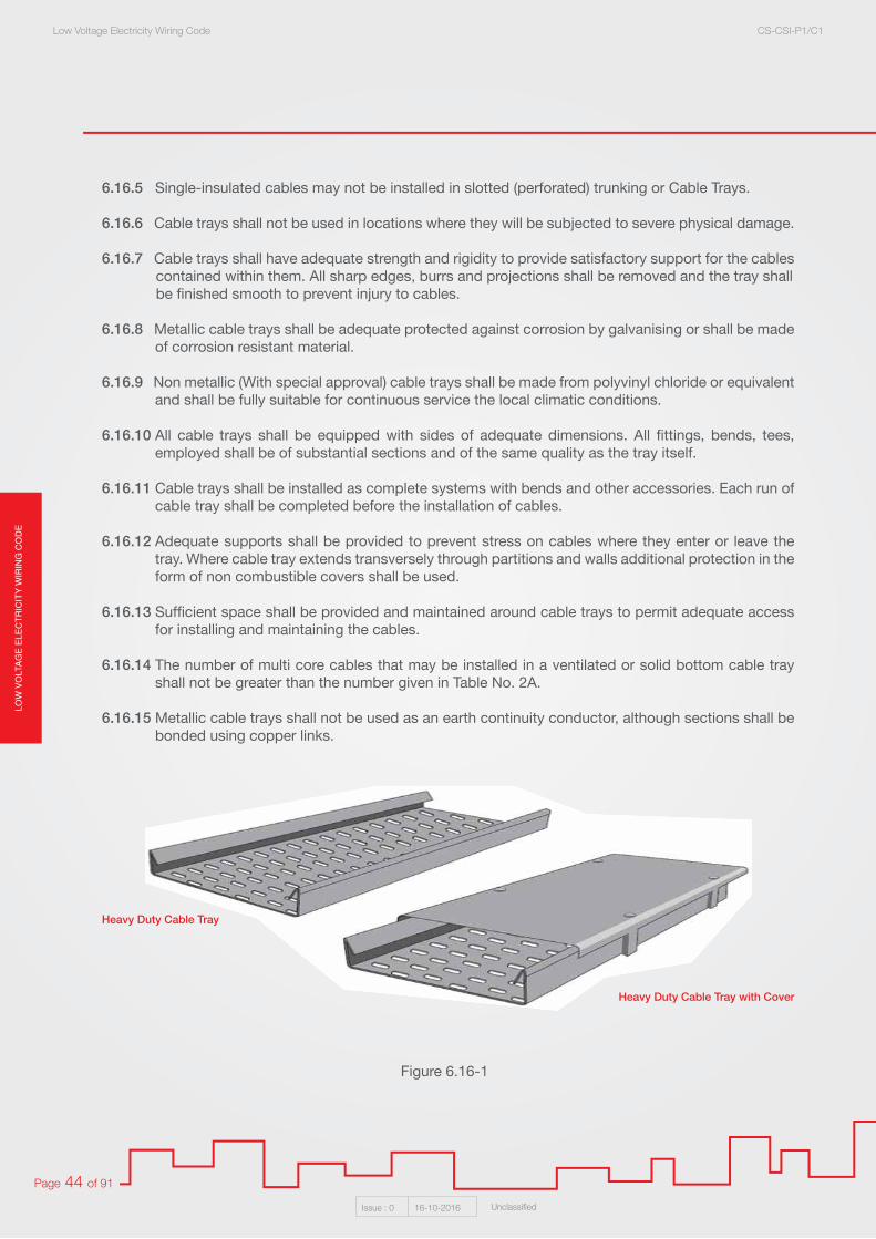
LOW
VO
LTA
GE
ELE
CT
RIC
ITY
WIR
ING
CO
DE
Low Voltage Electricity Wiring Code CS-CSI-P1/C1
Issue : 0 16-10-2016 Unclassified
Page 44 of 91
6.16.5 Single-insulated cables may not be installed in slotted (perforated) trunking or Cable Trays.
6.16.6 Cable trays shall not be used in locations where they will be subjected to severe physical damage. 6.16.7 Cable trays shall have adequate strength and rigidity to provide satisfactory support for the cables
contained within them. All sharp edges, burrs and projections shall be removed and the tray shall be finished smooth to prevent injury to cables.
6.16.8 Metallic cable trays shall be adequate protected against corrosion by galvanising or shall be made of corrosion resistant material.
6.16.9 Non metallic (With special approval) cable trays shall be made from polyvinyl chloride or equivalent and shall be fully suitable for continuous service the local climatic conditions.
6.16.10 All cable trays shall be equipped with sides of adequate dimensions. All fittings, bends, tees, employed shall be of substantial sections and of the same quality as the tray itself.
6.16.11 Cable trays shall be installed as complete systems with bends and other accessories. Each run of cable tray shall be completed before the installation of cables.
6.16.12 Adequate supports shall be provided to prevent stress on cables where they enter or leave the tray. Where cable tray extends transversely through partitions and walls additional protection in the form of non combustible covers shall be used.
6.16.13 Sufficient space shall be provided and maintained around cable trays to permit adequate access for installing and maintaining the cables.
6.16.14 The number of multi core cables that may be installed in a ventilated or solid bottom cable tray shall not be greater than the number given in Table No. 2A.
6.16.15 Metallic cable trays shall not be used as an earth continuity conductor, although sections shall be bonded using copper links.
Figure 6.16-1
Heavy Duty Cable Tray
Heavy Duty Cable Tray with Cover

LOW
VO
LTAG
E E
LEC
TR
ICIT
Y W
IRIN
G C
OD
ELow Voltage Electricity Wiring Code CS-CSI-P1/C1
Issue : 0 16-10-2016 Unclassified
Page 45 of 91
Figure 6.16-26.17 Cable Trunking Systems:
6.17.1 Cable trunking may be employed for housing single core cables at special locations where it is difficult to install conduits.
They may be of metallic or non metallic (With special approval) construction.
Non metallic cable trunking shall be constructed from non combustible insulation material such as polyvinyl chloride, which shall be fully suitable for use in the conditions.
Metallic cable trunking shall be adequately protected against corrosion by galvanising or shall be made of corrosion resistant material.
All cable trunking shall be provided with removable covers.
6.17.2 Cable trunking shall, generally, be run exposed and the trunking shall be completely erected before drawing in the cables. Where adequate means of access is readily available throughout its length, cable trunking may be concealed.
Note: Cable Trunking and Cable Tray shall be run exposed or otherwise accessible after installation, throughout its length, for the purpose of removing or installing cables.
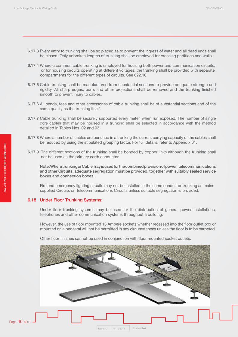
LOW
VO
LTA
GE
ELE
CT
RIC
ITY
WIR
ING
CO
DE
Low Voltage Electricity Wiring Code CS-CSI-P1/C1
Issue : 0 16-10-2016 Unclassified
Page 46 of 91
6.17.3 Every entry to trunking shall be so placed as to prevent the ingress of water and all dead ends shall be closed. Only unbroken lengths of trunking shall be employed for crossing partitions and walls.
6.17.4 Where a common cable trunking is employed for housing both power and communication circuits, or for housing circuits operating at different voltages, the trunking shall be provided with separate
compartments for the different types of circuits. See 622.10
6.17.5 Cable trunking shall be manufactured from substantial sections to provide adequate strength and rigidity. All sharp edges, burrs and other projections shall be removed and the trunking finished smooth to prevent injury to cables.
6.17.6 All bends, tees and other accessories of cable trunking shall be of substantial sections and of the same quality as the trunking itself.
6.17.7 Cable trunking shall be securely supported every meter, when run exposed. The number of single core cables that may be housed in a trunking shall be selected in accordance with the method detailed in Tables Nos. 02 and 03.
6.17.8 Where a number of cables are bunched in a trunking the current carrying capacity of the cables shall be reduced by using the stipulated grouping factor. For full details, refer to Appendix 01.
6.17.9 The different sections of the trunking shall be bonded by copper links although the trunking shall not be used as the primary earth conductor.
Note: Where trunking or Cable Tray is used for the combined provision of power, telecommunications and other Circuits, adequate segregation must be provided, together with suitably sealed service boxes and connection boxes.
Fire and emergency lighting circuits may not be installed in the same conduit or trunking as mains supplied Circuits or telecommunications Circuits unless suitable segregation is provided. 6.18 Under Floor Trunking Systems:
Under floor trunking systems may be used for the distribution of general power installations, telephones and other communication systems throughout a building.
However, the use of floor mounted 13 Ampere sockets whether recessed into the floor outlet box or mounted on a pedestal will not be permitted in any circumstances unless the floor is to be carpeted.
Other floor finishes cannot be used in conjunction with floor mounted socket outlets.
Figure 6.18

LOW
VO
LTAG
E E
LEC
TR
ICIT
Y W
IRIN
G C
OD
ELow Voltage Electricity Wiring Code CS-CSI-P1/C1
Issue : 0 16-10-2016 Unclassified
Page 47 of 91
6.19 Conduits:
HINT: The use of different Final Circuits in a common conduit or switch drops in shared conduits is not permitted. All cables that are not armoured, or that do not have a metallic sheath, must be installed in PVC or metal conduits or trunking throughout their entire length.
6.19.1 Types of Conduit:
Only exposed galvanised steel or rigid, high impact, heavy gauge PVC conduit shall be used for any installation where conduit is to be installed. No conduits of any kind shall be used for wiring within substation or Main Low voltage panel room, Only M.I.C.C. (Mineral-insulated copper-clad cable) / P.V.C. sheathed cables or fire rated cables shall be used in these locations.
P.V.C. and galvanised conduit shall not be mixed on any length of run without the prior approval for the purpose by the Qatar General Electricity & Water Corporation “KAHRAMAA“.
6.19.2 Rigid Metallic Conduit:
The metallic conduit and its accessories shall form a continuous metallic sheath of adequate strength surrounding the cables throughout the length of the conduit.
6.19.3 Metallic conduits shall not be run under floor tiles of buildings.
6.19.4 The bores of all conduits shall be smooth and free from projections and/or sharp edges which may injure the wires or prevent them being drawn in. The internal edges of the ends of all lengths of conduit shall be raised or chamfered before assembling into position.
6.19.5 All runs of conduit shall be assembled complete with all necessary accessories and the whole
firmly attached to the structure of the building before any wires are drawn in. All wires shall be drawn through the covers of inspection and other fittings installed for the purpose.
6.19.6 All thread, vice marks, tool marks and breaks in the protective coating on metallic conduit and/or conduit fittings shall be painted with a steel preserving paint immediately after erection.
6.19.7 No run of conduit shall exceed 10 meters between adjacent draw in points, nor certain more than two right angle bends, sets or other deviations, from the straight line.
6.19.8 Inspection couplings or draw in boxes shall be used where necessary in straight runs of conduits for draw in purposes and shall be placed so that cables can be inspected and, if necessary, withdrawn throughout the life of installation.

LOW
VO
LTA
GE
ELE
CT
RIC
ITY
WIR
ING
CO
DE
Low Voltage Electricity Wiring Code CS-CSI-P1/C1
Issue : 0 16-10-2016 Unclassified
Page 48 of 91
6.19.9 Where conduit and or conduit fittings are attached to switches, distribution boards, boxes or other equipment, smooth bore male brass brushes and flanged couplings shall be used.
Figure 6.19.9
6.19.10 Circular or hexagonal heavy locknuts shall be used at all positions where running joints are required and care shall be taken to see that they seat firmly and evenly into mating faces of couplings or other adjacent accessories.
Figure 6.19.10
6.19.11 Where exposed to water, rain or weather, all covers shall be arranged or fitted with machined joints and or fitted with durable gaskets such that water cannot penetrate.
6.19.12 Except where provision is made for fastening, conduits shall be saddled to the structure of the building within 15 cms of each terminal box, angle box, bend or other conduit fitting and at intervals
not less than 1.50 meters couplings and through type drawing boxes shall be counted as part of a straight run of conduit.
6.19.13 All boxes, bends and other accessories shall be of the same material as the conduit and shall have the same protective coatings. Grey cast iron boxes etc. may be used with metallic conduit, but shall be finished in the same manner as the conduit to which they are directly attached.
6.19.14 The number of single core P.V.C. insulated non-sheathed cables run in metallic conduit shall be such as to permit easy drawing of the cables. The actual number of cables drawn into any conduit shall not go greater than the number given in Table No. 04.
6.19.15 The minimum size of metallic conduit that may be used in electrical installations shall be 20 mm other sizes of conduits shall be limited to the following diameter:
25 mm, 32 mm, 38 mm And 50 mm
6.19.16 Galvanised conduit boxes used for all electrical accessories including light switches and socket outlet shall be fitted with brass earth terminal.

LOW
VO
LTAG
E E
LEC
TR
ICIT
Y W
IRIN
G C
OD
ELow Voltage Electricity Wiring Code CS-CSI-P1/C1
Issue : 0 16-10-2016 Unclassified
Page 49 of 91
6.20 Rigid Non Metallic Conduits:
Rigid non metallic conduit may be employed in general electrical installations provided it is made from polyvinyl chloride or equivalent material that have been certified as suitable for use at ambient temperatures up to 55oC, non hygroscopic and self extinguishing type.
6.20.1 Rigid PVC Conduit Shall Not Be Used in the Following Locations:
1. Where exposed to the outside ambient temperature.
2. Where it may be affected by chemicals to cause determination in its construction.
3. Any part of a Medical Building’s installations.
4. Petrol stations and forecourts.
5. The same room as a diesel generator.
6. Plant room, lift motor rooms and lift shafts.
7. Substations/Electric Rooms.
HINT: refer to QCDD regulations in additional to above.
6.20.2 The inside and outside surfaces or non metallic conduits shall smooth and free from burrs and similar defects. The interior and ends of conduit fittings shall have no sharp edges and corners, shall be smooth and well rounded to permit easy drawing in of cable air prevent any damages to cable insulation.
6.20.3 The entries of non metallic conduit fittings shall be so designed that reliable tight joint can be made between the conduit and fittings. Vinyl cement shall be used to make all joints. A vinyl solvent shall be used for permanent joints and cement shall be used for expansion couplers.
6.20.4 Rigid non metallic conduits shall be so constructed that it is possible bend the conduit easily with
the aid of a bending spring and all conduit and conduit fittings shall be of the unthreaded type.
6.20.5 The minimum size of rigid non metallic conduit used for general electrical installations shall be 20 mm Ø. Other sizes of rigid non metallic conduits shall be of the following diameters:
25 mm, 32 mm, 38 mm and 50 mm.
6.20.6 The number of single core P.V.C. insulated non - sheathed cables run in one conduit shall be such that it permits easy drawing of the cables. The actual number of cables drawn into any conduit shall not be greater than the number given in Table No. 04.
6.20.7 A separate insulated earth wire shall be drawn into all rigid non metallic conduits for each circuit, the cables of which pass through the conduit.
6.20.8 Rigid non metallic conduits shall be installed generally in accordance with the requirements set out for metallic conduits shall allow for the longitudinal expansion and contraction of the conduits.
6.20.9 Where a lighting fitting is suspended from a non metallic conduit box, care shall be taken to ensure that the temperature of the box does not exceed the permitted safe temperature of the material and is fitted with screwed metal insert clips. The mass suspended from the box shall not exceed 2 Kg.
6.20.10 Electrical conduits, where required to be distinguished from pipelines of other services, shall use orange as the basic identification colours.
6.20.11 P.V.C. conduit boxes for all electrical accessories including light switches and socket outlets etc. shall have a fitted brass fixing sockets tapped for 3.5 metric threads.

LOW
VO
LTA
GE
ELE
CT
RIC
ITY
WIR
ING
CO
DE
Low Voltage Electricity Wiring Code CS-CSI-P1/C1
Issue : 0 16-10-2016 Unclassified
Page 50 of 91
6.21 Metallic Flexible Conduits:
6.21.1 Flexible conduits may be employed for connecting electrical motors and other equipment subject to adjustment of position and vibration to the fixed wiring.
6.21.2 Flexible conduits may be of the metallic type only.
Metallic flexible conduits shall not be used as the sole means of providing earth continuity and a separate earth continuity conductor of appropriate size shall be provided.
Figure 6.21.2
6.21.3 In damp and wet locations all flexible conduits shall be of the type that prevents the ingress of water and moisture.
6.21.4 Flexible conduits shall only be run exposed and shall be so positioned that they are not susceptible to mechanical damage. Where necessary flexible conduits shall be adequately supported.
6.21.5 The ends of flexible conduits shall be securely anchored to the fixed conduit or equipment to which it is attached by approved flexible conduit adapters that maintain effective mechanical continuity securely in position without distorting it.
The flexible conduit shall not be used as part of the earth conductor. A separate earth conductor shall be installed to comply with the same requirements for rigid conduit installations.
Figure 6.21.5
6.21.6 The maximum length of a flexible conduit run shall be 2.50 meters. Where flexible conduit is installed less than 1.50 meters above a floor in a position where it may be easily disturbed or reached, it shall be supported at intervals not exceeding 300 mm, except where terminating at motors or at other equipment which requires a free length of flexible conduit to provide for normal movement.
LOW
VO
LTAG
E E
LEC
TR
ICIT
Y W
IRIN
G C
OD
ELow Voltage Electricity Wiring Code CS-CSI-P1/C1
Issue : 0 16-10-2016 Unclassified
Page 51 of 91
6.22 Segregation of Circuits:
6.22.1 Where an installation comprises extra low voltage or telecommunication or fire alarm circuits, as well as circuits operating at low or medium voltage, precautions shall be taken in accordance with the following to prevent both electrical and physical contact between the cables of the various types of circuit. See 6.17.4
These Types of Circuits Shall Be Divided into the Following Categories:
• Category No. 01 Circuits: Circuits other than fire alarm circuit operating at low voltage and supplied directly from a mains supply system.
• Category No. 02 Circuits: All low and extra low voltage circuits. • Category No. 03 Circuits: Fire alarm circuits. • Category No. 04 Circuits: All telecommunications circuits e.g. radio, telephone, sound distribution,
burglar alarm, bell, and call circuits which are not supplied directly from a mains supply system.
6.22.2 Cables of Category No. 01 Circuits shall not be drawn into the same conduit, pipe, trunking, duct, or run on the same cable tray, as cable Category No. 02 unless the latter cables are insulated to the same degree for the highest voltage present the Category No. 01 Circuits.
6.22.3 Cables in Category No. 01 Circuits shall not, in any circumstances be drawn into the same circuit trunking or duct which has the cables of Category No. 03 Circuits.
6.22.4 Cables in Category No. 01 Circuits shall not, in any circumstances be drawn into the same circuit trunking or duct which has the cables of Category No. 04 Circuits.
6.22.5 Cables in Category No. 04 circuits relating to their own specific system shall be installed remotely from another in their own conduit, trunking duct or pipe.
6.22.6 Cables in Categories 02, 03 and 04 shall not, in any circumstances be drawn into the same conduit, or duct.
6.22.7 Where a common channel or trunking is used to contain cables of the three categories, it shall be separated by means of a continuous partition of fire resisting material.
6.22.8 Cables of categories 01 and 03 circuits shall not, in any circumstances are contained in a common multi core cable, flexible cable or flexible cord.
6.23 Multi-Storey Buildings: 6.23.1 A three phase neutral and earth rising main system shall be installed in a common riser duct with tap
off units at each floor level to each customer.
The rising electrical duct will house the rising main, the tap off units and the Qatar General Electricity & Water Corporation “KAHRAMAA” meters. From the meter, conduit will be run to the distribution board located within each customer’s premises.

LOW
VO
LTA
GE
ELE
CT
RIC
ITY
WIR
ING
CO
DE
Low Voltage Electricity Wiring Code CS-CSI-P1/C1
Issue : 0 16-10-2016 Unclassified
Page 52 of 91
623.2 Each tap off unit shall fitted with a Moulded Case Circuit Breaker (MCCB), rated to suit electrical loading of the premises and prospective fault level at the point of the installation.
623.3 Types of rising mains for multi storey buildings :
1. Rising Main Bus Bar Trunking.
2. M.I.C.C. / P.V.C. Cable.
3. S.W.A. / P.V.C. Cable.
6.23.4 In case of (2) and (3), a maximum of 4 (Four) floors may be supplied by either system, higher floors can be accepted up to 10 (Ten) floors for cables size not more than 240 mm2 and other shall be with special approval.
6.23.5 The bus-bar trunking system shall be fully type tested, as per BS EN 60439 Part 01 : 2011 (Type - Tested And Partially Type - Tested Assemblies) and BS EN 60439 Part 02 : 2011 (Particular Requirements For Bus-bar Trunking Systems “ Bus-ways”).
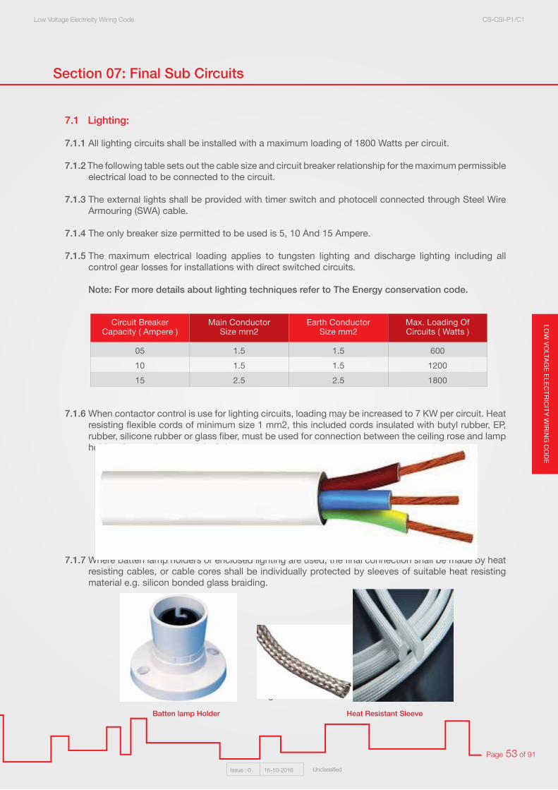
LOW
VO
LTAG
E E
LEC
TR
ICIT
Y W
IRIN
G C
OD
ELow Voltage Electricity Wiring Code CS-CSI-P1/C1
Issue : 0 16-10-2016 Unclassified
Page 53 of 91
Section 07: Final Sub Circuits
7.1 Lighting:
7.1.1 All lighting circuits shall be installed with a maximum loading of 1800 Watts per circuit.
7.1.2 The following table sets out the cable size and circuit breaker relationship for the maximum permissible electrical load to be connected to the circuit. 7.1.3 The external lights shall be provided with timer switch and photocell connected through Steel Wire
Armouring (SWA) cable.
7.1.4 The only breaker size permitted to be used is 5, 10 And 15 Ampere.
7.1.5 The maximum electrical loading applies to tungsten lighting and discharge lighting including all control gear losses for installations with direct switched circuits.
Note: For more details about lighting techniques refer to The Energy conservation code.
7.1.6 When contactor control is use for lighting circuits, loading may be increased to 7 KW per circuit. Heat resisting flexible cords of minimum size 1 mm2, this included cords insulated with butyl rubber, EP, rubber, silicone rubber or glass fiber, must be used for connection between the ceiling rose and lamp holders for pendant type light fittings.
Figure 7.1.6
7.1.7 Where batten lamp holders or enclosed lighting are used, the final connection shall be made by heat resisting cables, or cable cores shall be individually protected by sleeves of suitable heat resisting material e.g. silicon bonded glass braiding.
Figure 7.1.7
Circuit Breaker Capacity ( Ampere )
Main ConductorSize mrn2
Earth ConductorSize mm2
Max. Loading Of Circuits ( Watts )
05 1.5 1.5 600
10 1.5 1.5 1200
15 2.5 2.5 1800
Batten lamp Holder Heat Resistant Sleeve

LOW
VO
LTA
GE
ELE
CT
RIC
ITY
WIR
ING
CO
DE
Low Voltage Electricity Wiring Code CS-CSI-P1/C1
Issue : 0 16-10-2016 Unclassified
Page 54 of 91
7.1.8 Lighting in kitchen, stairs, lift rooms and LV rooms to be by fluorescent.
7.1.9 Suspended False Ceiling Installations:
Light fittings (Both Tungsten And Fluorescent) shall be supported by one of the following methods:
1. Direct support from the false ceiling framework (Providing the Ceiling Has Been Designed to Withstand the Weight of the Light Fittings). When using this method it shall be possible to completely withdraw the light fitting from the ceiling without damage to the ceiling or reducing its rigidity.
2. Metal conduit support from the underside of the structural slab. A fluorescent fitting shall have a minimum of two conduit support. Each conduit shall terminate at the fitting by means of a screwed coupling and male brass bush to give leveling adjustment of the fitting.
Figure 7.1.9 - 2
3. Metal threaded rod support from the underside of the structural slab.
A fluorescent fitting shall have a minimum of two rods for surface or flush mounting provided when flush mounted, adequate support shall be given.
Each rod shall be secured into the structural ceiling by means of raw bolt or other approved means and at the light fitting, by means of nuts and washers to give the leveling adjusting required.
Figure 7.1.9 - 3
Screwed Coupling Brass Bush
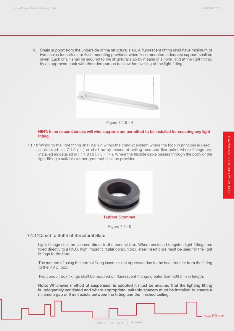
LOW
VO
LTAG
E E
LEC
TR
ICIT
Y W
IRIN
G C
OD
ELow Voltage Electricity Wiring Code CS-CSI-P1/C1
Issue : 0 16-10-2016 Unclassified
Page 55 of 91
4. Chain support from the underside of the structural slab. A fluorescent fitting shall have minimum of two chains for surface or flush mounting provided, when flush mounted, adequate support shall be given. Each chain shall be secured to the structural slab by means of a hook, and at the light fitting, by an approved hook with threaded portion to allow for levelling of the light fitting.
Figure 7.1.9 - 4
HINT: In no circumstances will wire supports are permitted to be installed for securing any light fitting.
7.1.10 Wiring to the light fitting shall be run within the conduit system where the loop in principle is used, as detailed in : 7.1.9 ( 1 ) or shall be by means of ceiling rose and flex outlet where fittings are, installed as detailed in : 7.1.9 ( 2 ), ( 3 ), ( 4 ). Where the flexible cable passes through the body of the light fitting a suitable rubber grommet shall be provider.
Figure 7.1.10
7.1.11Direct to Soffit of Structural Slab:
Light fittings shall be secured direct to the conduit box. Where enclosed tungsten light fittings are fixed directly to a P.V.C. high impact circular conduit box, steel insert clips must be used for the light fittings to the box.
The method of using the normal fixing inserts is not approved due to the heat transfer from the fitting to the P.V.C. box.
Two conduit box fixings shall be required on fluorescent fittings greater than 600 mm in length.
Note: Whichever method of suspension is adopted it must be ensured that the lighting fitting is adequately ventilated and where appropriate, suitable spacers must be installed to ensure a minimum gap of 6 mm exists between the fitting and the finished ceiling.
Rubber Grommet
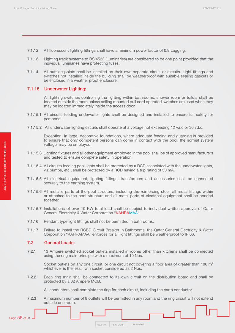
LOW
VO
LTA
GE
ELE
CT
RIC
ITY
WIR
ING
CO
DE
Low Voltage Electricity Wiring Code CS-CSI-P1/C1
Issue : 0 16-10-2016 Unclassified
Page 56 of 91
7.1.12 All fluorescent lighting fittings shall have a minimum power factor of 0.9 Lagging.
7.1.13 Lighting track systems to BS 4533 (Luminaries) are considered to be one point provided that the individual luminaries have protecting fuses.
7.1.14 All outside points shall be installed on their own separate circuit or circuits. Light fittings and switches not installed inside the building shall be weatherproof with suitable sealing gaskets or be enclosed in a weather proof enclosure.
7.1.15 Underwater Lighting:
All lighting switches controlling the lighting within bathrooms, shower room or toilets shall be located outside the room unless ceiling mounted pull cord operated switches are used when they may be located immediately inside the access door.
7.1.15.1 All circuits feeding underwater lights shall be designed and installed to ensure full safety for personnel.
7.1.15.2 All underwater lighting circuits shall operate at a voltage not exceeding 12 va.c or 30 vd.c.
Exception: In large, decorative foundations, where adequate fencing and guarding is provided to ensure that only competent persons can come in contact with the pool, the normal system voltage may be employed.
7.1.15.3 Lighting fixtures and all other equipment employed in the pool shall be of approved manufacturers and tested to ensure complete safety in operation.
7.1.15.4 All circuits feeding pool lights shall be protected by a RCD associated with the underwater lights, viz.pumps, etc., shall be protected by a RCD having a trip rating of 30 mA.
7.1.15.5 All electrical equipment, lighting fittings, transformers and accessories shall be connected securely to the earthing system.
7.1.15.6 All metallic parts of the pool structure, including the reinforcing steel, all metal fittings within or attached to the pool structure and all metal parts of electrical equipment shall be bonded together.
7.1.15.7 Installations of over 10 KW total load shall be subject to individual written approval of Qatar General Electricity & Water Corporation “KAHRAMAA“.
7.1.16 Pendant type light fittings shall not be permitted in bathrooms.
7.1.17 Failure to install the RCBD Circuit Breaker in Bathrooms, the Qatar General Electricity & Water Corporation “KAHRAMAA” enforces for all light fittings shall be weatherproof to IP 66.
7.2 General Loads:
7.2.1 13 Ampere switched socket outlets installed in rooms other than kitchens shall be connected using the ring main principle with a maximum of 10 Nos.
Socket outlets on any one circuit, or one circuit not covering a floor area of greater than 100 m2
whichever is the less. Twin socket considered as 2 Nos.
7.2.2 Each ring main shall be connected to its own circuit on the distribution board and shall be protected by a 32 Ampere MCB.
All conductors shall complete the ring for each circuit, including the earth conductor.
7.2.3 A maximum number of 8 outlets will be permitted in any room and the ring circuit will not extend outside one room.
LOW
VO
LTAG
E E
LEC
TR
ICIT
Y W
IRIN
G C
OD
ELow Voltage Electricity Wiring Code CS-CSI-P1/C1
Issue : 0 16-10-2016 Unclassified
Page 57 of 91
HINT: No socket outlets shall be permitted in bathrooms, shower rooms, or toilets Only weatherproof IP 66 C/WRCBO protection and cover shall be used with special approval as per provided technical justifications.
7.2.4 Shaver socket, Hair Clippers and Similar Appliances outlets may be installed in bathrooms provided they comply with BSI BS EN 61558-2-5 (Particular requirements and tests for transformer for shavers, power supply units for shavers and shaver supply units).
That is, the type of electrical fitting for the water proof facility may be disregarded on the condition to install a protective cover to ensure non seepage of water splashes into the internal elements when using the bathroom.
Failure to install the RCBO Circuit Breaker in Bathrooms, the Qatar General Electricity & Water Corporation “KAHRAMAA“ enforces for all light fittings shall be weatherproof to IP 66.
7.2.5 Extract fans shall be controlled from a separate switch of the same type as the light switch and shall be situated adjacent to it, except kitchen extract fans.
7.2.6 One socket outlet of 15 A rating may be connected to a single phase and neutral circuit wired with 3 x 2.5 mm2 cables, protected by a circuit breaker not exceeding 16 A.
7.2.7 One special purpose outlet of 15 or 16 Ampere rating may be connected to a single phase and neutral circuit wired with 2.5 mm2 cable, protected by a circuit breaker not exceeding 16 Ampere.
7.2.8 No socket outlet shall be mounted within two meters of any tap, sink or basin, in any kitchen, cloakroom, etc. without the special approval of Qatar General Electricity & Water Corporation “KAHRAMAA” in each case. Socket outlets shall not be mounted at locations where they are liable to come into physical contact with fabrics or other material that may catch fire due to transmission of heat.
7.2.9 No spur outlets will be permitted from any ring main wired in 4 mm2 phase conductor and 2.5 mm2
earth conductor.
7.2.10 Socket outlets rendered inaccessible, by appliances fastened in place or of a size to be not easily moveable will not be permitted.
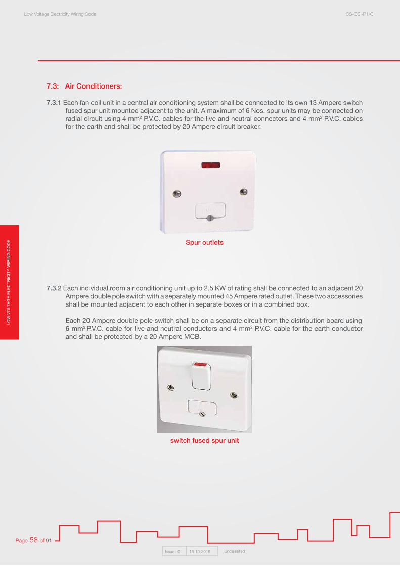
LOW
VO
LTA
GE
ELE
CT
RIC
ITY
WIR
ING
CO
DE
Low Voltage Electricity Wiring Code CS-CSI-P1/C1
Issue : 0 16-10-2016 Unclassified
Page 58 of 91
7.3: Air Conditioners:
7.3.1 Each fan coil unit in a central air conditioning system shall be connected to its own 13 Ampere switch fused spur unit mounted adjacent to the unit. A maximum of 6 Nos. spur units may be connected on radial circuit using 4 mm2 P.V.C. cables for the live and neutral connectors and 4 mm2 P.V.C. cables for the earth and shall be protected by 20 Ampere circuit breaker.
7.3.2 Each individual room air conditioning unit up to 2.5 KW of rating shall be connected to an adjacent 20 Ampere double pole switch with a separately mounted 45 Ampere rated outlet. These two accessories shall be mounted adjacent to each other in separate boxes or in a combined box.
Each 20 Ampere double pole switch shall be on a separate circuit from the distribution board using 6 mm2 P.V.C. cable for live and neutral conductors and 4 mm2 P.V.C. cable for the earth conductor and shall be protected by a 20 Ampere MCB.
Spur outlets
switch fused spur unit

LOW
VO
LTAG
E E
LEC
TR
ICIT
Y W
IRIN
G C
OD
ELow Voltage Electricity Wiring Code CS-CSI-P1/C1
Issue : 0 16-10-2016 Unclassified
Page 59 of 91
7.3.3 Each individual room air conditioning unit above 2.5 KW of rating shall be connected to a 30 Ampere double pole switch, with a separately mounted 45 Ampere rated outlet.
Each 30 Ampere double pole switch shall be on a separate circuit from the distribution board using 6 mm2 P.V.C. cable for live and neutral conductors and 6 mm2 P.V.C. cable for the earth conductor and shall be protected by 30 Ampere MCB.
7.3.4 A split air conditioning unit with both sections adjacent on opposite side of a wall or in the roof, it is required for a weatherproof isolating device to be placed adjacent to the compressor.
HINT: Flexible wires will not permitted to be used for power connection of Air conditioning units.
7.3.5 Split a/c electrical connection wiring shall be arranged as the following:
1. 2 x 6 + 1 x 4 mm single core PVC from the MCB to the DP switch.
2. The same from the DP switch to pulling box (optional).
3. The same going direct to the isolator adjacent to the outdoor unit in the roof / Ground or Basement Floor through 25 mm2 rigid PVC conduit.
4. The 25 mm2 PVC conduit can be laid adjacent to the a/c cooling gas pipe.
5. The same from the isolator to the outdoor unit.
7.4 Water pumps: 7.4.1 Where water pumps are installed on the per flat or villa basis, the means of control shall be from a
separate switch, of suitable rating for the pump in question and shall be connected as follows:
7.4.2 All single phase water pump motors with a rating of up to 0.37 KW(1/2 HP) shall be controlled from 13 Ampere switched fuse spur with pilot light, fitted with 5 Ampere fuse and connected into a ring main circuit or 5 Ampere switch with pilot light on its own separate 5 Ampere circuit from the distribution board.
7.4.3 All single phase water pump motors with a rating of more than 0.37 KW and all three phase motors shall be on their own separate circuit and provided with control apparatus incorporating a suitable device affording protection against excess current in the motor or in the cables between the device and the motor.
7.4.4 Each motor starter for all three phase motor shall incorporate a phase failure device which will automatically disconnect the supply from the motor. This device must be manually reset.
HINT: Should Refer to Section 08 (Electric Motors, Circuits and Controllers) for more details about required protection and starting arrangements for motors rated above 0.37 KW.
7.4.5 All water pump motor installed remotely from the controlling device shall be provided with an additional means of isolation immediately adjacent to the motor.
7.4.6 Where the controlling device and or the means of isolation is installed outside the building, it shall be of a weather proof design. Water pumps for any installation shall be located a minimum distance of 2 meters from any water tank.

LOW
VO
LTA
GE
ELE
CT
RIC
ITY
WIR
ING
CO
DE
Low Voltage Electricity Wiring Code CS-CSI-P1/C1
Issue : 0 16-10-2016 Unclassified
Page 60 of 91
7.5 Extract fans in the kitchen shall be connected from kitchen ring main and controlled from separate 13 Ampere switched fuse spur unit fitted with 13 Ampere fuse.
Figure 7.57.6 All items of electrical equipment installed outside a building exposed to the weather conditions, or
in a damp area shall be of weather proof type or be enclosed in a weather proof enclosure of degree IP 54 minimum.
7.7 Particular Items Relevant to Residential Accommodation:
7.7.1 Minimum Acceptable Number of Electrical Power Accessories in Each Room of a Dwelling Are as Follow:
1. Kitchen
04 Nos.: 13 Ampere switched socket outlets (For General Purpose). Over 12 m2 for floor area 8 x 13 A switched socket outlets for general purpose.
01 No.: 45 Ampere cooker control unit without a 13 Ampere switched socket outlet.
01 No.: 20 Ampere double pole switch for water heater (If required).
Figure 7.7.1 - 1
13 Amp switched socket 45 Amp cooker control unit 20 Amp double pole switch

LOW
VO
LTAG
E E
LEC
TR
ICIT
Y W
IRIN
G C
OD
ELow Voltage Electricity Wiring Code CS-CSI-P1/C1
Issue : 0 16-10-2016 Unclassified
Page 61 of 91
2. All Bedrooms:
04 Nos.: 13 Ampere switched socket outlets (For General Purpose).
3. Majlis Or Lounge:
06 Nos. : 13 Ampere switched socket outlets (For General Purpose). See also 7.2.3.
4. Dining Room:
04 Nos. : 13 Ampere switched socket outlets (For General Purpose).
5. Hall (Corridor):
02 Nos. : 13 Ampere switched socket outlets on opposite walls to avoid need for flex across doorway.
7.7.2 The 13 Ampere socket outlets in the kitchen shall be connected on their own individual ring main from the distribution board using 4 mm2 PVC cable for the live and neutral conductors and 2.5 mm2 for the earth conductor and shall be protected by a 30 Ampere MCB. All conductors shall complete the ring for each circuit including the earth conductors.
7.7.3 If more than 8 sockets are to be installed in the kitchen, a second ring main shall be used. In no circumstances will socket outlets installed in the kitchen be permitted to be connected to circuits comprising socket outlets in other rooms;
7.7.4 Where a residence is supplied with a Three Phase supply, more than one phase will be permitted in any one room or area provided that a minimum distance of 2 metres is obtained between any outlets on other phases.
7.7.5 Where switch boxes contain more than one phase, for group switching approved barrier switch boxes may be used. The unit must be labelled to indicate that 415 Volts exists at the box.
7.7.6 A 45 Ampere cooker control unit shall be installed in the kitchen, on its own separate circuit from the distribution board and shall be protected by a 30 Ampere MCB. Socket outlets on cooker control units are not permitted. Wiring for this unit shall be 6 mm2 P.V.C. cable with 6 mm2 cable for the earth conductor.
7.7.7 A 45 Ampere cable connector unit suitable for use with cookers shall be installed at low level or final connection to cooker. In no circumstances shall the cooker be connected direct to the cooker control unit.
The cable used between the control unit and cable outlet to the cooker shall be the same as detailed above.
Cable connector unitFigure 7.7.7
LOW
VO
LTA
GE
ELE
CT
RIC
ITY
WIR
ING
CO
DE
Low Voltage Electricity Wiring Code CS-CSI-P1/C1
Issue : 0 16-10-2016 Unclassified
Page 62 of 91
7.7.8 Mounting Heights Of Electrica Accessories from bottom edge:
Lighting Switch: 1250 mm AFFL Ceiling Fan Regulator: 1250 mm AFFL 13 Ampere Socket Outlets: 450 mm AFFL 20 Ampere DP Switch for A/C Unit: Adjacent to A/C Unit 20 Ampere DP Switch for Water Heater: 1250 mm AFFL 13 Ampere Socket in Kitchen Above Work Top: 250 Above Work Cooker Control Unit: 1600 mm AFFL Cooker Low Lever Connection Outlet: 450 mm AFFL Shaver Socket Outlet: 1250 mm AFFL
Note: It must be appreciated that these dimensions are to be used only as guide but Qatar General Electricity & Water Corporation “KAHRAMAA” would strongly recommended that these figures are generally adopted otherwise will be through special approval as per provided justification.
7.7.9 In every dining room, family room, majlis, bedroom and similar room with general access, excluding kitchens, bathrooms, toilets and showers, sockets shall be installed so that no point along the floor line of any wall is more than 2 meters horizontally from a socket outlet. This shall apply only to rooms of size 15 m x 15 m or smaller.
7.8 Bathroom or Toilet:
HINT: Special provisions are required for the protection against electric shock of persons in locations containing a bath or shower. Such provisions, as listed in the following clauses, must also be applied in other similar situations where persons are likely to be partly clothed and in contact with water, with or without footwear. Similar locations would include washrooms, toilets, wudu areas in mosques, etc.
The following principal requirements must be met for bathrooms/Tolilet and similar locations:
7.8.1 No socket-outlets are permitted except those supplied by an isolating transformer and complying with BS EN 61558-2-5(Particular requirements and tests for transformer for shavers, power supply units for shavers and shaver supply units). (e.g. ‘shaver’ socket-outlet).
7.8.2 All Final Circuits (including lighting, water heater, extract fan, etc) must be protected by a RCD of residual current rating 30 mA and complying with BS EN 61008. Such protection may be grouped across several Circuits at the Final Distribution Board. However, fan-coil units mounted in a ceiling void in a bathroom may be provided with 100mA RCD protection.
7.8.3 All Appliances, Luminaires and other Accessories must have a minimum level of moisture ingress protection ofIPX4;
7.8.4 Appliances, Luminaires or other Accessories may not be installed within Arm’s Reach of a bath, shower or similar facility. However, such items are permitted within the room containing a bath or shower at a distance greater than Arm’s Reach from the bath, provided that the requirements of clauses 7.8.1, 7.8.2 and 7.8.3 above are complied with. In addition, all switches associated with such equipment must be installed outside the bathroom or provided with a cord-pull switch; Appliances, Luminaires or Accessories which are within Arm’s Reach of a bath, shower or similar facility must be supplied by SELV or PELV and have a minimum level of ingress protection of IPX5.

LOW
VO
LTAG
E E
LEC
TR
ICIT
Y W
IRIN
G C
OD
ELow Voltage Electricity Wiring Code CS-CSI-P1/C1
Issue : 0 16-10-2016 Unclassified
Page 63 of 91
HINT: In no circumstances will more than one phase be permitted in bathrooms, toilets or washrooms of residence.
7.8.5 Underwater lighting must be supplied by SELV at a maximum Voltage of 12 V a.c. or 30 V d.c. and with ingress protection IPX8.
Note: items which are within a distance of Arm’s Reach but are inaccessible to persons need not comply with clause 7.8.4. For example, water pumps installed under a bath which are not accessible without removal of covers requiring a tool.
7.9 Water Heaters:
7.9. 1 If a heater up to 3 KW single phase is installed in the kitchen it shall be controlled from a 20 Ampere double pole switch which may also be located in the kitchen.
7.9.2 Final connection to each water heater shall be made from an unswitched flex outlet plate mounted adjacent to the heater.
7.9.3 When the water heater is located in the bathroom, shower room or toilet, the 20 Ampere DP controllingswitch shall be located immediately outside the room. Final connection to the water heater shall be by means of an unswitched flex outlet plate mounted adjacent to the heater.
7.9.4 Each water heater shall be complete with an earthing terminal provided by the manufacturer. The earth terminal shall be located immediately adjacent to the live and neutral terminals. All terminals shall be housed within a suitable, removable access cover.
7.9.5 Each water heater shall be a separate circuit from the distribution board, protected by a 15 Ampere RCBO. Wiring from the outlet shall be in 2.5 mm2 P.V.C. cable for the live and neutral conductors and 2.5 mm2 PVC cable for the earth.
7.9.6 For water heater in excess of 3 KW, Qatar General Electricity & Water Corporation “KAHRAMAA” approval shall obtained for each particular installation.
7.9.7 Wiring from the flex outlet to the water heater shall be in three core heat resisting 2.5 mm2 sheathed butyl cable or its equivalent.
7.9.8 Where possible, the water heater shall be positioned as close as possible to the controlling switch but must be a minimum of 2 meters away from any part of a bath or shower unit.
Cord pull switchFigure 7.8
LOW
VO
LTA
GE
ELE
CT
RIC
ITY
WIR
ING
CO
DE
Low Voltage Electricity Wiring Code CS-CSI-P1/C1
Issue : 0 16-10-2016 Unclassified
Page 64 of 91
Section 08: Electric Motors, Circuits and Controllers
All motors shall be rated at 415 Volts 50 Hz., Three Phase or 240 Volts 50 Hz., Single Phase as required. Other voltage will not be accepted.
Note.01: When motors are starting and running up to full speed, a current higher than the normal full load amps (FLA) is drawn. This starting current results in a Voltage drop.
The permissible Voltage drop levels are as stated in the Electricity Wiring Code. The motor starting current and resulting Voltage drop is reduced when motor starters employing current limiting starting equipment are used.
8.1 Protection minimum Requirements:
8.1.1 All motors including AC compressors over 1 HP for single phase and 3 HP for three phase shall be provided with means of automatic disconnection from the supply in the event of excess current flow or drop in voltage of over 15% completed with time delay for auto re-start to avoid voltage dip.
8.1.2 The method of starting motors shall restrict the current to limits laid down by the Qatar General Electricity & Water Corporation “KAHRAMAA“.
1. Motors with a name plate rating of up to and including 11 KW (15 HP).
2. Motors with a name plate rating of above 11 KW (15 HP).
Motors that fall within category (1) may be connected for direct online starting with over current protection.
Motors that fall within category (2) shall not in any circumstances connected for direct on line starting but shall be arranged for reduced voltage starting e.g. open or closed transition Star / Delta Starting. Auto transmission starting or other approved arrangement.
Note.02: It is preferred that modern practice is followed by the provision of variable frequency drives, where appropriate, to limit the starting current but also to afford further control and reduce the energy usage. Other starting techniques such as star-delta, primary resistance starter, auto transformer or electronic soft starter may also be considered depending on the application.
8.1.3 All motors over 1 HP for single phase and 3 HP for three phases shall be provided with current limiting starting equipment to effectively keep the starting current within the following limits:
8.1.4 All motors rated at 11 KW (15 HP) and above shall be fitted with thermostatic control elements within the motor actuating directly the control circuit of the motor and disconnecting it from the supply in the event of a temperature rise exceeding limits for its insulation class.
Rating of motor Maximum permissible starting current
1 HP to 5 HP 5 x full-load current
Above 5 HP and up to 50 HP 2 x full-load current
Above 50 HP and up to 150 HP 1.5 x full-load current
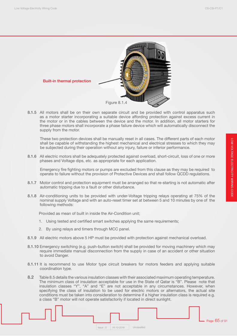
LOW
VO
LTAG
E E
LEC
TR
ICIT
Y W
IRIN
G C
OD
ELow Voltage Electricity Wiring Code CS-CSI-P1/C1
Issue : 0 16-10-2016 Unclassified
Page 65 of 91
8.1.5 All motors shall be on their own separate circuit and be provided with control apparatus such as a motor starter incorporating a suitable device affording protection against excess current in the motor or in the cables between the device and the motor. In addition, all motor starters for three phase motors shall incorporate a phase failure device which will automatically disconnect the supply from the motor.
These two protection devices shall be manually reset in all cases. The different parts of each motor shall be capable of withstanding the highest mechanical and electrical stresses to which they may be subjected during their operation without any injury, failure or inferior performance.
8.1.6 All electric motors shall be adequately protected against overload, short-circuit, loss of one or more phases and Voltage dips, etc. as appropriate for each application.
Emergency fire fighting motors or pumps are excluded from this clause as they may be required to operate to failure without the provision of Protective Devices and shall follow QCDD regulations.
8.1.7 Motor control and protection equipment must be arranged so that re-starting is not automatic after automatic tripping due to a fault or other disturbance.
8.1.8 Air-conditioning units to be provided with under-Voltage tripping relays operating at 75% of the nominal supply Voltage and with an auto-reset timer set at between 5 and 10 minutes by one of the following methods:
Provided as mean of built in inside the Air-Condition unit;
1. Using tested and certified smart switches applying the same requirements;
2. By using relays and timers through MCC panel.
8.1.9 All electric motors above 5 HP must be provided with protection against mechanical overload.
8.1.10 Emergency switching (e.g. push-button switch) shall be provided for moving machinery which may require immediate manual disconnection from the supply in case of an accident or other situation to avoid Danger.
8.1.11 It is recommend to use Motor type circuit breakers for motors feeders and applying suitable coordination type.
8.2 Table 8.5 details the various insulation classes with their associated maximum operating temperature. The minimum class of insulation acceptable for use in the State of Qatar is “B”. Please note that insulation classes “Y”, “A” and “E” are not acceptable in any circumstances. However, when specifying the class of insulation to be used for electric motors or alternators, the actual site conditions must be taken into consideration to determine if a higher insulation class is required e.g. a class “B” motor will not operate satisfactorily if located in direct sunlight.
Built-in thermal protection
Figure 8.1.4

LOW
VO
LTA
GE
ELE
CT
RIC
ITY
WIR
ING
CO
DE
Low Voltage Electricity Wiring Code CS-CSI-P1/C1
Issue : 0 16-10-2016 Unclassified
Page 66 of 91
8.3 In general, motors shall be of the drip proof type and be totally enclosed, fan cooled. Where motors are required to operate in hazardous areas or are required for a special purpose, the design of the motor shall be suitable for this application.
The terminal box for all motors shall be weatherproof. All motors shall be of such construction as to make the temperature as uniform as possible in the different parts of the windings and core during operation, thus avoiding excessive heating at any point.
8.4 Motor control panels shall be fitted with an ammeter or ammeters in each motor circuit.
8.5 The following table details the type of insulation materials used, for each class of motor construction together with its maximum winding operating temperature, as detailed below:
8.6 Isolation of Equipment:
Any distribution board, item of plant, e.g. pumps, motor central chillers, etc., located in a position remote from the protective device at the origin of the supply cable shall have a local isolator mounted adjacent to that equipment for operational and maintenance safety. Isolation of motors other than those employing direct on line starters shall be achieved by means of a lock off push button or other approved means (MCC-Motor Control Center) located adjacent to the motor and controlling the starter coil.
8.7 Poly phase motors which are not part of packaged unit equipment and having continuous rating and intended for long period of usage shall be energy efficient motors, tested to relevant international standards like IEC/TS 60034-2-3:2013.The efficiency class of the motors to be used shall be of minimum IE2 (High Efficiency) as detailed in IEC 60034-30-1:2014.
Note.03: Energy efficient motors have higher performance due to key design improvements and more
accurate manufacturing tolerances. Lengthening the core and using lower electrical loss steel, thinner stator laminations reduce electrical losses. Improved bearings and a smaller more aerodynamic cooling fan further increase the efficiency (2 to 8% More Efficient than Standard Motors).
8.8 Wiring and control diagrams must be permanently fixed, adjacent to motors.
Class Of Insulation
Specification Of The Insulation Of TheMotor Windings
Max. Winding Temperature
Y Cotton, Silk, Paper, Wood, Cellulose, Fibre, Etc., Not Impregnated Or Immersed In Oil.
90
A Material Of Class Y But Impregnated With Natural Resins, Cellulose Esters, Insulating Oils, Etc. Also Laminated Wood, Varnished Paper,
Cellulose Acetate Film Etc.
105
E Synthetic Resin Enamels, Cotton And Paper LaminatesWith Formaldehyde Bonding.
120
B Mica, Glass Fibre, Asbestos, Etc., With Suitable Bonding Substances Such As Built Up Mica, Glass Fibre And Asbestos Laminates.
130
F Materials Of Class B With Bonding Materials Of HigherThermal Stability.
155
H Glass Fibre And Asbestos Material And Built Up MicaWith Silicone Resins.
180
C Mica, Ceramics, Glass, Quartz And Asbestos Without Binders But WithSilicone Resins Of High Thermal Stability.
180
Figure 8.5

LOW
VO
LTAG
E E
LEC
TR
ICIT
Y W
IRIN
G C
OD
ELow Voltage Electricity Wiring Code CS-CSI-P1/C1
Issue : 0 16-10-2016 Unclassified
Page 67 of 91
Section 09: Power Factor Correction
9.1 General requirements
9.1.1 Every installation shall have a power factor within the range of 0.9 lagging to unity. A Lagging power factor of less than 0.9 shall be improved by the installation of suitable correction equipment.
The low voltage Capacitor banks to be installed and connected to the MDB / M.L.V.P. in order to improve the power factor and to maintain the overall power factor between 0.9 Lag and Unity.
9.1.2 Individual Power factor correction capacitor can also be connected to major inductive equipments in order that the overall compensation by means of group correction and individual correction shall achieve the required minimum power factor of 0.90 Lag measured at MSB/MDB panel.
9.1.3 The target power factor for all Electrical design purpose shall be Minimum 0.90 lag.
Design calculations for power factor correction equipment shall be submitted for the following categories of installations
• All Industrial installations irrespective of load.• All Agricultural farms irrespective of load.• All bulk customers of any category.• All Commercial, Government & mixed use installations, of demand load of 210kW /350A and
above.• All residential buildings & Developments with central air-conditioning system and having an
overall demand load of 210kW/350 A and above.• All residential buildings & Developments where a private substation is insisted by KAHRAMAA.
9.1.4 Detuned Capacitors shall be installed where the non-linear loads constitute a major part of the load based on design verification and /or site audit.
HINT: If the percentage non-linear load in the installation exceeds 15% of total load then detuned capacitors shall be used.
9.1.5 The assessment shall be made for any characteristics of equipments likely to have harmful effect on KAHRAMAA supply network, shall be audited and remedial measures considered for the installation. The provisions under section 3 requirements of safety shall be complied.
Any other method of Power factor compensation shall be to the approval by KAHRAMAA prior to installation
9.1.6 Capacitor banks and associated components shall be suitably designed and selected to ensure reliable and continuous operation at a maximum system Voltage of 440 V and at a maximum ambient temperature of 50˚C.
9.1.7 If a permanently connected capacitor unit is applied for induction motors, the capacitor unit rating must not exceed 90% of the no-load reactive power of the motor.
The above is required in order to avoid the occurrence of self excitation on run-down condition of the motor.

LOW
VO
LTA
GE
ELE
CT
RIC
ITY
WIR
ING
CO
DE
Low Voltage Electricity Wiring Code CS-CSI-P1/C1
Issue : 0 16-10-2016 Unclassified
Page 68 of 91
Clarification:
The benefit to this type of application is as follows:
• The reactive power requirements of the motor are only supplied when the motor is running, This effectively provides automatic control of power factor.
• Total equipment costs are reduced as the motor controller performs the capacitor switching function.
• The voltage profile to the motor is improved.
A major drawback to this type of capacitor application, however, is improper sizing of the capacitor can lead to motor failure; too large of a capacitor leads to self-excitation of the motor, which can result in motor insulation failure.
Self-excitation occurs when the capacitive reactive current from the capacitor is greater than the magnetizing current of the induction motor. When this occurs, excessive voltages can result on the terminals of the motor. This excessive voltage can cause insulation degradation and ultimately result in motor insulation failure.
9.2 Specifications for capacitor Units
9.2.1 The capacitor units shall be dry, self-healing type with individual discharge resistors shall be protected against internal faults, over pressure, etc. and shall fully comply with and tested to the requirements of the International Electro-technical Commission Publication No IEC 60831, Part-1 and Part-2.
Hint: The use of oil containing PCB (poly-chlorinated biphenyls) is strictly prohibited.
9.2.2 The Voltage rating of capacitor units shall be 480 V as a minimum.
9.2.3 Capacitor units shall be temperature class D.
9.2.4 Capacitor units shall be metal encapsulated.
9.2.5 Capacitor units shall be capable of continuous operation in accordance with the over-voltage and over current requirements of IEC 6083.
9.2.6 Built-in discharge resistors for capacitors shall be sized to ensure safe discharge of the capacitor to less than 50 V in one minute after a switch off and capacitors should not restart until a minimum 3 minutes after the restoration of the supply.
HINT: Manual means of switching or connecting the discharge circuit is not permitted.
9.2.7 Each capacitor shall be provided with a permanent nameplate, which includes the following information:
a. Year of manufacture;b. Rated reactive power;c. Rated Voltage (rms);d. Number of Stages;e. Rated frequency;f. Statement of discharge device;g. Short-circuit current.h. Name of the manufacturer and contact details.
9.2.8 Capacitors and related components such as regulators, indicating instruments, contactors, etc, shall be capable of withstanding local environmental conditions.
LOW
VO
LTAG
E E
LEC
TR
ICIT
Y W
IRIN
G C
OD
ELow Voltage Electricity Wiring Code CS-CSI-P1/C1
Issue : 0 16-10-2016 Unclassified
Page 69 of 91
9.2.9 Contactors shall be suitably rated and designed for capacitive back to back switching with pre insertion resistors and be able to withstand switching surges. Contactors shall isolate all three phases on switch off of the capacitor bank or on loss of supply voltage.
9.2.10 Each capacitor step shall be protected against conditions of overload and short-circuit by means of suitably rated overcurrent relays and suitably rated HRC fuses (current limiting type) respectively.
9.2.11 The capacitor panel must be provided with a suitably rated main incomer isolating switch. This shall be a three-pole isolator or MCCB. The handle of the incomer isolator or MCCB shall be interlocked with the door to ensure that the capacitor bank is de-energised when the door is open.
9.2.12 The cooling requirement of the capacitor banks shall be as per the project specification and manufacturer’s requirement. Where forced ventilation equipment is used for cooling, a thermostat is required to be installed to sense the ambient surrounding temperature and to switch off the capacitor in the event of temperature rise.
9.3 Specifications for series reactors to prevent amplification of system harmonics
Employing variable speed drives, welding machines or similar devices in Circuits lead to occurrence of harmonics while can lead to disturbances in the system and may cause capacitor failure. To minimise this risk, harmonic filter reactors must be employed in series with capacitors.
The three phase series reactors to be connected in series with each capacitor unit for harmonic current suppression and to prevent resonance shall be iron cored type with copper windings. The reactor shall comply with the IEC. 60076-6. The Capacitors and the Reactors combination shall be tuned below the lowest harmonic present in a particular distribution system.
9.4 Automatic power factor Controllers
Wherever automatic power factor controllers are installed the target minimum power factor shall be 0.90 lagging. The controller shall be programmed to have appropriate switching sequence. The method of switching for Capacitor shall be as per manufacturer’s recommendation.
9.5 Capacitor Bank enclosure
In large Installations where large capacitor bank is installed for both indoor and outdoor applications, the capacitor bank and allied components shall be housed in suitable enclosure of rust proof material like GI, Stainless steel or GRP of suitable thickness having front access with provision for lock arrangement. The degree of ingress protection shall suit the site requirement as per IEC 60529.
9.6 Installation
The installation of Capacitor banks shall be generally in accordance with the manufacturer’s recommendations, clearance shall be provided around the capacitor bank as per the manufacturer’s recommendation. Where a capacitor is installed for power factor correction it must be provided with a means for its prompt automatic discharge immediately the supply is disconnected. This requirement shall not apply to a small capacitor, such as that integral with a fluorescent lighting fitting.
HINT: A capacitor bank shall not be a part of the motor control centre, main LV panel (MDB) or sub-main panel, but it shall be accommodated in a separate cubicle with appropriate clearance as per manufacturer recommendations and safety aspects.

LOW
VO
LTA
GE
ELE
CT
RIC
ITY
WIR
ING
CO
DE
Low Voltage Electricity Wiring Code CS-CSI-P1/C1
Issue : 0 16-10-2016 Unclassified
Page 70 of 91
9.7 Routine tests and Type tests for capacitors
9.7.1 Each capacitor unit shall be routine tested by the manufacturer as per IEC 60831 part 1 & 2. Each capacitor bank shall be subject to routine test by the manufacturer as per IEC 60439.
• Inspection, including checking of clearance, dimensions etc.
• Di-electric Test
9.7.2 Type tests for capacitor unit and capacitor banks shall be carried out as per IEC 60831 part 1 & 2 and IEC 60439-1 respectively.
9.7.3 All site tests/commissioning tests (Electrical & Mechanical) shall be conducted by the contractor’s representative to ensure quality and functional properties of device.
9.7.4 All manufacturers’ test certificate shall be submitted to KAHRAMAA for approval as a part of MDB(s) submittal prior to installation of equipment.
9.8 Applicable Standards for capacitor banks
The capacitor banks shall conform in design, material, construction and performance to the latest editions of the IEC standards, in particular to the following Standards
Relevant international standards for Capacitors Banks
IEC 60831-1 & 2Shunt power capacitors of the self-healing type for A.C. systems having a rated voltage up to and including 1000 V.
IEC 61921 Power capacitors Low voltage power factor correction banks.
IEC 60076-6 Power transformers - Part 6: Reactors
IEC 60085-1 Electrical insulation - Thermal evaluation and designation.
IEC 60439-1Low-Voltage Switchgear and Control gear Assemblies - Part 1: Type- Tested and Partially Type-Tested Assemblies.
IEC 60947-1 Low-voltage Switchgear and Control gear - Part 1: General Rules
IEC 60947-2Low-voltage Switchgear and Control gear - Part 2: Circuit-Breakers.
IEC 60947-4-1Low-voltage Switchgear and Control gear - Part 4-1: Contactors andMotor-starters.
IEC 60529 Degree of protection provided enclosures (IP code)
LOW
VO
LTAG
E E
LEC
TR
ICIT
Y W
IRIN
G C
OD
ELow Voltage Electricity Wiring Code CS-CSI-P1/C1
Issue : 0 16-10-2016 Unclassified
Page 71 of 91
Section 10: Emergency, Standby Systems and Fire Alarm Installations
HINT: QCDD (Qatar Civil Defense Department) regulations have the priority than any related clauses under this section
10.1 Emergency Systems:
10.1.1 Emergency systems shall, generally be provided in places of assembly where artificial illumination is required such as buildings subject to occupancy by large numbers of people, hotels, theatres, multi storey buildings, sports arenas, hospitals and similar premises and in all such premises adequate illumination shall be provided from the emergency systems to safely evacuate personnel.
All stairways, landing, exits and similar locations shall be provided with emergency lighting. This system shall also be capable of providing power to essential services and equipment in hospitals, refrigeration plants, in bulk cold stores, air conditioning systems, fire pumps, industrial process equipment where an interruption of the normal supply would produce serious hazards, and for all other similar functions.
10.1.2 The emergency system shall have adequate and rating for the emergency operation of all equipment connected to the emergency system.
10.1.3 The emergency system shall be so designed and constructed that, in the event of failure of the normal supply to or within the building, emergency lighting and emergency power, where such is required, will be immediately available.
10.1.4 The type of emergency system adopted shall depend upon the nature of the occupancy and the load and one of the following systems may be provided:
1. Storage Battery: A storage battery of suitable rating and capacity along with inverters etc., to supply and maintain at not less than 90% of the system voltage the total load of the circuits supplying emergency lighting and emergency power for the minimum period of 1½ hours. The system shall be complete with automatic battery charging means.
2. Generator Set:A generator set driven by a prime mover of suitable rating and capacity to supply and maintain at system voltage the total load of the circuits supplying emergency lighting and emergency power, including lifts.
Means shall be provided for automatically starting the prime mover on failure of the normal supply. Automatic means shall also be provided for transferring from the normal supply to the emergency supply those loads necessary during emergency. For hospitals, the transition time from the instant of failure of the normal supply to the emergency supply shall not exceed 10 seconds.
3. Individual unit equipment battery for emergency illumination shall comprise a rechargeable battery, a battery means, lighting fixture and a relaying device arranged to energise the lamps automatically upon failure of normal supply. The batteries shall be of suitable rating and capacity to supply and maintain, at not less than 90 % of the normal battery voltage, the total lamp load for a period of at least 1½ hours.
10.2 Standby Systems: 10.2.1 In addition to the emergency systems, due consideration shall also be given on the selection and
rating of such systems to afford standby power also to non emergency systems during a failure of normal supply.
10.2.2 For standby systems a manual or automatic change over from normal supply to stand by supply
shall be provided.

LOW
VO
LTA
GE
ELE
CT
RIC
ITY
WIR
ING
CO
DE
Low Voltage Electricity Wiring Code CS-CSI-P1/C1
Issue : 0 16-10-2016 Unclassified
Page 72 of 91
Notes: 1. In no circumstances shall there be any possibility to back feed from the generator set to the main network.
2. Qatar General Electricity & Water Corporation “KAHRAMAA” approval shall be obtained for the type of change over system adapted from normal supply to emergency or stand by supply.
10.2.3 for The Specifications for Main Failure Standby Generators refer to QCDD regulations.
10.3 Main Low Voltage Switchgear(MDB):
10.3.1 The switchgear provided for use with the scheme must comply with the current Qatar General Electricity & Water Corporation “KAHRAMAA” requirement for medium voltage switchgear and be of adequate capacity for the total supply and the generator.
10.3.2 The Air Circuit Breakers (ACB) and where applicable contactors used in conjunction with the scheme shall be Four (4) Pole. The bus-coupler shall be also of Four (4) Pole ACB, and of same current rating.
10.3.3 Where the generator is installed adjacent to a substation and the substation supplies only that one consumer, ACB’s must be used for control of the mains and generators supplies.
10.3.4 In cases other than 1007.3 above the use of contactors will be considered, but automatic fault breaking switches must be supplied on the mains and generator sides of the contractors. The final decision on the use of contactors will be made by Qatar General Electricity & Water Corporation “KAHRAMAA“.
10.4 Protection:
10.4.1 The protection provided on the mains circuit breaker shall be in accordance with the Qatar General Electricity & Water Corporation “KAHRAMAA“specification. See Section 04.
10.4.2 The generator circuit breaker must be supplied with over current and restricted earth fault protection and the necessary current transformers. The setting ranges of the restricted earth fault relay to be 10 - 40% of the circuit breaker rating. The over current setting range must be compatible with the generator rating.
10.5 Instrumentation:
10.5.1 The Incoming Mains Panel Is to Be Supplied with the Following Instruments:
1. Ammeters in each phase, using separate current transformers from the protection circuits, scale to be appropriate for rating of the circuit breaker.
2. Reset table maximum demand indicators (May be incorporated with the Ammeters), giving 30 minutes maximum demand.
3. Voltmeters in each phase giving phase / neutral voltage.
4. Power Factor Meter.
10.5.2 The Generator Panel Is to Be Supplied with the Following Instruments:
1. Ammeters in each phase, using separate current transformers from the protection circuits, scale to be appropriate for rating of the circuit breaker.
2. Maximum demand indicators ( May Be Incorporated With The Ammeters ) giving 30 minutes maximum demand.
LOW
VO
LTAG
E E
LEC
TR
ICIT
Y W
IRIN
G C
OD
ELow Voltage Electricity Wiring Code CS-CSI-P1/C1
Issue : 0 16-10-2016 Unclassified
Page 73 of 91
3. Voltmeters in each phase giving phase / neutral voltage.
4. Frequency meter scaled 45 - 55 Hz.
10.6 Earthing:
The generator and mains supply will normally use a common neutral earthing system and will use the earth provided by Qatar General Electricity & Water Corporation “KAHRAMAA“. Generator neutral busbar must be fitted with a removable link to enable generator set earth to be removed if fault occurs and for maintenance.
10.7 Control Scheme:
10.7.1 Automatic changeover from the mains supply to the generator is to be initiated when one of the following conditions exists for more than 3 seconds, as detailed below:
1. Failure of one or more phase.
2. Line voltage outside nominal voltage by 15% or more.
10.7.2 The mains and generator circuit breakers / contactors to be electrically and mechanically interlocked to prevent paralleling of the mains and generator.
10.7.3 The mains and generator circuit breakers / contactors to be manually and electrically operated. 10.7.4 A control switch to be provided to give the following positions:
1. Auto start.
2. Manual starts with separate buttons for start and stop.
3. Test to simulate mains failure.
4. Off.
The above switch to be operated with the generator running without shutting down the generator.
10.7.5 Lamps to be provided to indicate:
1. Mains Healthy.
2. Mains ON.
3. Generator ON.
4. Generator Fails To Start.
10.7.6 The delay on start timer on interruption of the mains supply shall be adjustable 0 - 30 seconds period.
10.7.7 The delay and shutdown timer on restoration of the mains supply shall be adjusted 0 - 15 minutes period.
10.7.8 All relays and control circuits for the automatic changeover scheme to be mounted on a separate wall or floor in each panel (Wall or floor mounting to be specified in each contract). This panel may also contain the relays controls etc for the month auto start scheme.

LOW
VO
LTA
GE
ELE
CT
RIC
ITY
WIR
ING
CO
DE
Low Voltage Electricity Wiring Code CS-CSI-P1/C1
Issue : 0 16-10-2016 Unclassified
Page 74 of 91
10.7.9 All internal cables to be ferruled and identified and all terminals and connections numbered. All wiring to be loomed and clipped with straps and cleats.
10.710 All control fuses shall be H.R.C. cartridge type.
10.7.11 All relays and timers used in the circuits are to be dust free plug in type to allow for easy replacement.
10.8 All windings shall be tropically impregnated and the whole of the works to be designed for operations on the very dusty environment with an ambient of 50º C and of and humidity 80%.
10.9 For government or public sector projects the choice of diesel generators, auxiliary plant, switchgear, installation, connection to mains, protection, fuel handling, civil works etc., shall require approval from Qatar General Electricity & Water Corporation “KAHRAMAA”.
10.10 For private sector projects the choice of diesel generators shall remain the prerogative of the consultants and contractors involved although approval from Qatar General Electricity & Water Corporation “KAHRAMAA“ will still be required for the connection of mains supply.
10.11 Cable termination at generator and switchgear must be well spaced and of adequate dimensions to allow for easy jointing and acceptance of the size type and number of cables that the Qatar General Electricity & Water Corporation “KAHRAMAA” may specify.
10.12 Diesel fuel oil supply lines and electric cables must be segregated from each other.
10.13 Approval of Schemes:
All schemes must be submitted to Qatar General Electricity & Water Corporation “KAHRAMAA” for approval. KAHRAMAA reserves the right to refuse to connect any non approved scheme.
10.14 Fire Alarm Systems:
Hint: For Fire Alarm Installations refer to QCDD (Qatar Civil Defense Department) regulations.

LOW
VO
LTAG
E E
LEC
TR
ICIT
Y W
IRIN
G C
OD
ELow Voltage Electricity Wiring Code CS-CSI-P1/C1
Issue : 0 16-10-2016 Unclassified
Page 75 of 91
Section 11: Inspection and Testing
11.1 Internal Wiring Inspection and testing to be done by the Licensed Contractor:
11.1.1 Every New/Upgrade/Modification Electrical Installation shall during execution and on completion before applying for KM inspection be inspected and tested by a the project Licensed contractor and keep relevant records and test reports and to be submitted to KM along with inspection request except equipments which cannot tested before energizing.
All test reports to include project details and project numbers issued by KM and to be stamped and signed by the project licensed contractor/Authorized Supervision Consultant (if applicable).
11.1.2 Testing tools and apparatus serial numbers and calibration details to be included in the test reports.
11.1.3 Tests and inspections shall include but not limited to:
1. Insulation resistance Test.
2. Continuity of Ring and Final Circuit conductors.
3. Operation of Earth Leakage/Residual current Protection devices.
Note01: The insulation resistance tests between live conductors and between each live conductor and Earth shall be measured with a test voltage of 500V d.c.
Note02: To ensure keeping reliability, continuity and safety of Electrical Installations, it shall be inspected and tested on a periodic basis. The responsibility for periodic inspection and testing of Electrical Installations lies with the Owner of the Premises who shall request the services of a Licensed the Owner must also ensure that any necessary rectification work is carried out.
11.2 Main Low Voltage Switchgear(MDBs)/MSBs/MSBs/etc. Licensed contractor/Manfacturer inspections & tests:
11.2.1 Tests and inspections shall include but not limited to:
1. Visual inspection report.
2. On-site Insulation Resistance Tests:
An insulation resistance test shall be made at the incoming supply terminals of each and every distribution board and switch board to measure the outgoing circuits.
This test shall be made and passed satisfactorily before any completed installation or alteration to an existing installation, is connected to the Qatar General Electricity & Water Corporation “KAHRAMAA” supply.
For these tests, a D.C. Voltage not less than twice voltage of the supply shall be applied for the measurement of insulation resistance, except that for tests made on Main Low voltage circuits the voltage need not exceed 500 Volts D.C.
The following shall form the installation test at each and every distribution and switchboard:
1. Phase to phase insulation resistance.
2. Phase to neutral insulation resistance.

LOW
VO
LTA
GE
ELE
CT
RIC
ITY
WIR
ING
CO
DE
Low Voltage Electricity Wiring Code CS-CSI-P1/C1
Issue : 0 16-10-2016 Unclassified
Page 76 of 91
3. Phase to earth insulation resistance.
4. Neutral to earth insulation resistance.
These tests shall be carried out with fuse links in place, all circuit breakers closed, and all switches and main switch closed. The resultant insulation resistance for any of the above measurements shall not be less than 1 M.
Where practicable, so that all parts of the wiring may be tested, all lamps shall be removed and all current using apparatus shall be disconnected and all local switches controlling lamps or apparatus shall be closed.
Note: Where the removal of lamps and or disconnection of current using apparatus is impracticable,
the local switches controlling such lamps and or apparatus shall be open.
Notice Periodic Inspection and Testing:
A notice of such durable material as to be likely to remain easily legible throughout the life of the installation shall be fixed in a prominent position at or near the main distribution board of every installation upon completion of the work. The notice shall be neither inscribed in indelible characters nor smaller than those here illustrated and shall read as follows:
Important:
This installation should be inspected and tested annually by a maintenance contractors licensed by Qatar General Electricity & Water Corporation “KAHRAMAA”, and a report on its condition obtained.
Date of Last Inspection: ……....................................................... Date of Next Inspection: ..............................................................
11.2.2 ACB operation test (For MDBs).
11.2.3 REF test report (For MDBs).
11.3 Main and sub main Cables visual, insulation resistance & continuity test report.
HINT- 01: All test reports to include project details and project numbers issued by KM and to be stamped and signed by the project licensed contractor, Authorized Supervision Consultant (if applicable) and manufacturer.
HINT- 02: Testing tools and apparatus serial numbers and calibration details to be included in
the test reports.

LOW
VO
LTAG
E E
LEC
TR
ICIT
Y W
IRIN
G C
OD
ELow Voltage Electricity Wiring Code CS-CSI-P1/C1
Issue : 0 16-10-2016 Unclassified
Page 77 of 91
Section 12: Connected loads, MAX Demand and Diversity factors
12.1 Adding the individual full load current of all points of utilization for an electrical circuit (e.g. Socket’s outlets) will lead to over sizing the Circuit because actually the sum of individual loads often not equal to the actual load current required by the Circuit. So, in the load estimation diversity factors are applied.
This section gives the guidelines for the determination of the maximum demand and diversity for the electrical installations design and includes the current demand to be assumed for commonly used equipment in additional to the Diversity factors.
12.2 These Guidelines note provides diversity allowances for specific situations. The factors used may be increased or decreased by the designer depending on the intended use of the Electrical Installation.
The designer shall provide the relevant justification and calculation tables to KAHRAMAA along with electricity building permit documents.
12.3 The information and values given in this section are intended for highly recommended guidance with taking into account the state of Qatar enforcement to use the high energy efficient and energy conservation equipments and apparatus.
12.4 Only because it is impossible to specify all the appropriate allowances for diversity for every type of installation; some allowances call for special knowledge and experience.
12.5 The allowances for diversity in an Electrical Installation varies depending on many factors, these factors may include:
a. Type and nature of the Electrical Installation (residential, commercial, industrial, etc);b. Intended use of utilisation points (e.g. general use socket outlets for the connection of portable
Appliances compared to dedicated socket-outlets for a fixed connection);c. Number of utilisation points in a Circuit (e.g. a SMSB feed two FDBs compared to 10 FDBs); andd. Operating characteristics of the Connected Load (e.g. the use of a/c units in the state of Qatar
is essential in the summer and in many cases it will be running most of the time).
12.6 It is important to note that allowances for diversity in an Electrical Installation may vary between similar installation. Therefore, the designer of the Electrical Installation may select different allowances representing the intensity of usage (e.g. higher value for high usage Circuits, such as communal kitchens, lower value for lower occupancy dwellings, etc).
12.7 The factors given in Table No. B, therefore, may be increased or decreased as decided by the engineer responsible for the design of the installation concerned and relevant calculation sheets and justifications to be provided to KAHRAMAA.
12.8 The current demand of a final circuit is determined by summating the current demands of all points of utilisation and equipment in the circuit and where appropriate, making an allowance for diversity. Typical current demands to be used for this summation are given in Table No. A.
12.9 The current demand of a circuit supplying a number of final circuits shall be assessed by using the allowances for diversity given in Table No. B which is applied to the total current demand of all the equipment supplied by that circuit and not by summating the current demands of the individual final circuits obtained as outlined above. In Table No. B the allowances are expressed either the rated full load current of the current using equipment.
12.10 The use of other design currents for all the circuits have been determined, enabling the conductor sizes to be chosen, it is necessary to check that the limitation on voltage drops is met.

LOW
VO
LTA
GE
ELE
CT
RIC
ITY
WIR
ING
CO
DE
Low Voltage Electricity Wiring Code CS-CSI-P1/C1
Issue : 0 16-10-2016 Unclassified
Page 78 of 91
Note 01: If the actual Connected Load. Connected Load on socket-outlet Circuits are known then the designer may choose to use that specific values.
Note 02: Standby loads should not be considered when sizing the Final Distribution Boards and the designer to ensure that interlock to be provided.
Points Of Utilisation Of Current Using Appliance
Current Demand To Be Assumed
Lighting • Sum of wattage of all Luminaries or assume 50 W for each lighting point.
• Chandelier lighting point – 200 up to 500 W as per the designed number of lamps.
• Lamp wattage plus losses of associated control.Gear such as ballasts and capacitors for fluorescent Lighting.
13 A socket-outlets– (for general use for the connection of portable Appliances.
100 W each
13A socket-outlets/ flex outlets andindustrial socket outlets – (fixed Appliances)
Actual rating of Appliance
Water heater 1,500 W or actual rating of Appliance
Washing machine, dryer, dishwasher 1,500 W each or actual rating of Appliance
Cooker 3,000 W or actual rating
Fridge 300 W or actual rating
Motors (e.g. lifts) Actual rating
Air Conditioning 1200 W each 1 TON refrigerant
Table No. A
Current Demand to Be Assumed For Points of Utilisation
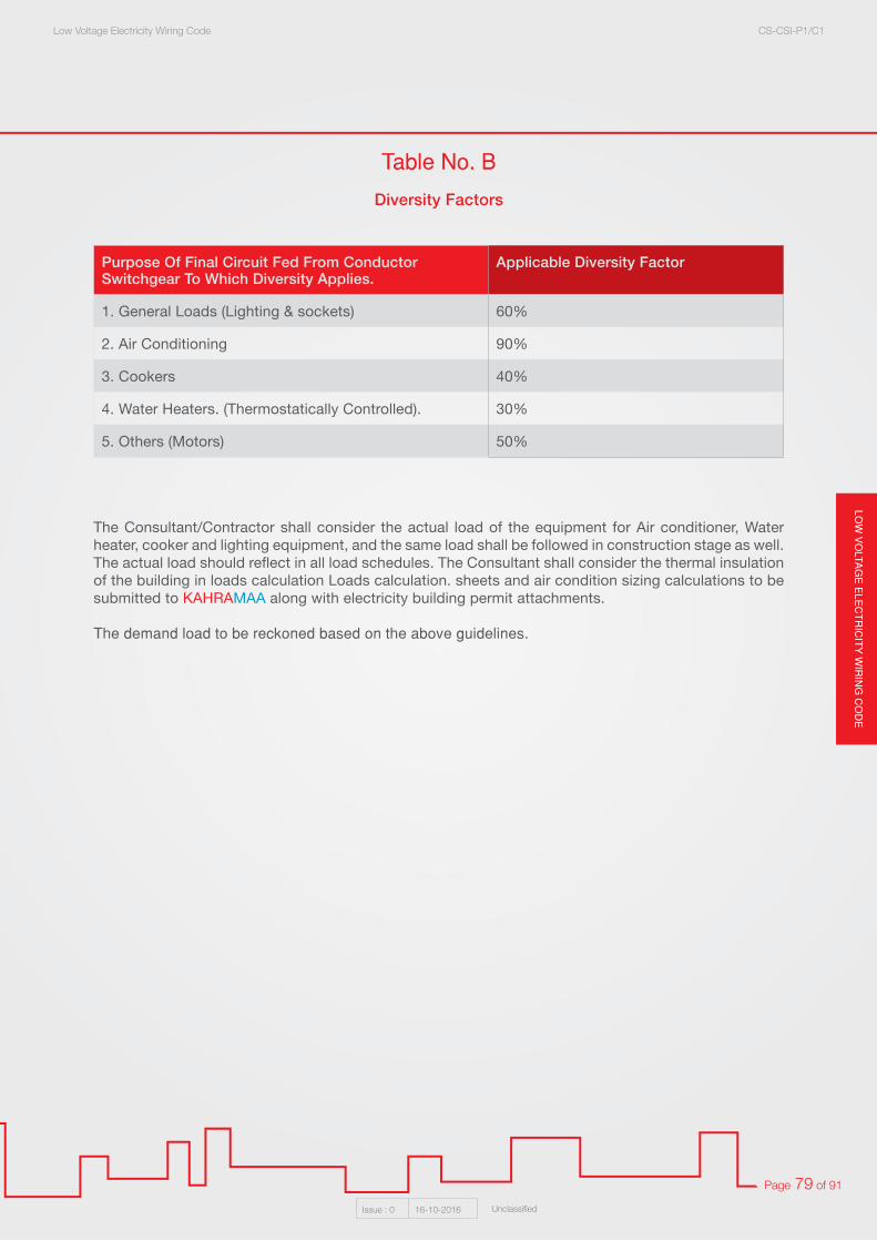
LOW
VO
LTAG
E E
LEC
TR
ICIT
Y W
IRIN
G C
OD
ELow Voltage Electricity Wiring Code CS-CSI-P1/C1
Issue : 0 16-10-2016 Unclassified
Page 79 of 91
Purpose Of Final Circuit Fed From Conductor Switchgear To Which Diversity Applies.
Applicable Diversity Factor
1. General Loads (Lighting & sockets) 60%
2. Air Conditioning 90%
3. Cookers 40%
4. Water Heaters. (Thermostatically Controlled). 30%
5. Others (Motors) 50%
Table No. B
Diversity Factors
The Consultant/Contractor shall consider the actual load of the equipment for Air conditioner, Water heater, cooker and lighting equipment, and the same load shall be followed in construction stage as well. The actual load should reflect in all load schedules. The Consultant shall consider the thermal insulation of the building in loads calculation Loads calculation. sheets and air condition sizing calculations to be submitted to KAHRAMAA along with electricity building permit attachments.
The demand load to be reckoned based on the above guidelines.

LOW
VO
LTA
GE
ELE
CT
RIC
ITY
WIR
ING
CO
DE
Low Voltage Electricity Wiring Code CS-CSI-P1/C1
Issue : 0 16-10-2016 Unclassified
Page 80 of 91
Appendix No. 1: Tables
Note: The Table of Fault Current Limiters Is Based On The Following Fuse Links:
1. Fuses up to and including 700 Amperes are English Electric Type - T.
2. Fuses of 800 Amperes and above are English Electric Type - TUV.
3. Equivalent fuses of other manufacture may be used.
Circuit Breaker RatingAmpere
Min. Fuse SizeAmpere
Max. Fuse Size( Supply Side )
Ampere
Max. Fuse Size( Load Side )
Ampere
Miniature Circuit Breakers ( MCB )05 - 1520 - 3540 - 60
6080
150
125150150
100125150
Mounded Case Circuit Breakers ( MCCB )E - Frame
05 - 1520 - 3540 - 60
65 - 100F - Frame
10152040
45 - 7585 - 100
115 - 125150
8080
125200
6080
100150200250300350
150250250250
400400400400400400400400
125200200200
350350350350350350350350
J And K Frame( With Adjustable Magnetic Trip )
50 - 7090
100125150200225
125150200250250350350
200250250300350450500
600600600600600600600
L – Frame( With Adjustable Magnetic Trip )
125 -150175
200 - 225300325350400
250400350450450500500
350400450600650650
1000
600600600600
100010001000
M - Frame( With Adjustable Magnetic Trip )
300325 - 350400 - 450
500600700800900
1000
400450500550800
1200160016001600
500550650
120012001200160016001600
600600
1000120012001600160016001600
Table No. 1Fault Current Limiters to Be Used to Give Short Circuit Protection up to 50 KA

LOW
VO
LTAG
E E
LEC
TR
ICIT
Y W
IRIN
G C
OD
ELow Voltage Electricity Wiring Code CS-CSI-P1/C1
Issue : 0 16-10-2016 Unclassified
Page 81 of 91
1. Single core insulated and sheathed cables and single core insulated non magnetic armoured cables:
1. Where single cores cables are installed in ventilated cable trays, the sum of the combined cross sectional area of all cables installed in the tray shall not exceed 50% of the interior cross sectional area of the cable tray.
2. Where single core cables are installed in solid bottom cable trays, the sum of the combined cross sectional area of all cables installed in the tray shall not exceed 40% of the interior cross sectional area of the cable tray.
2. Multi core armoured or non armoured cables:
1. Where multi core cables are installed in ventilated cable trays, the sum of the diameters of all cables installed shall not exceed 90% of the cable tray width and the cable shall be installed in a single layer.
2. Where multi core cables are installed in solid bottom cable trays, the sum of the diameters of all cables installed shall not exceed 80% of the cable tray width and the cables shall be installed in a single layer.
Table No. 2Maximum Number of Cables that May Be Installed in Surface Mounted Metal
of PVC Trunking
Number of Cables that May Be Installed on Cable Trays
Cable 1.5 2.5 4.5 6.0 10 16 25.0 35.0 50.0 70.0 95.0
Trunking 1/1.38 1/1.787/7.67 7/0.85 7/1.04 7/1.35 7/1.70 7/2.14 19/1.53 19/1.78 19/2.14 19/2.52
38 x 38
50 x 38
50 x 50
75 x 50
75 x 75
100 x 50
100 x 75
100 x 100
150 x 50
150 x 100
150 x 150
225 x 100
71
92
123
185
278
247
370
494
370
741
1112
1112
58
76
98
148
221
197
296
394
296
592
888
888
39
50
67
101
152
135
203
271
203
406
609
609
30
39
52
79
118
195
158
211
158
316
475
475
19
25
33
51
76
67
101
135
101
203
305
305
14
18
24
37
55
49
74
98
74
148
222
222
9
12
16
24
37
39
49
66
49
99
148
148
7
9
12
18
28
25
37
50
37
75
112
112
5
6
9
13
20
18
27
37
41
55
83
83
4
5
7
10
16
14
21
28
32
42
64
64
3
3
5
7
11
10
15
21
23
31
47
47
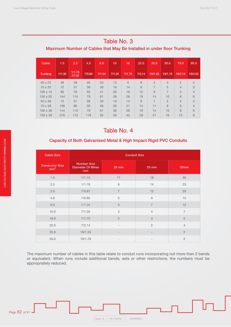
LOW
VO
LTA
GE
ELE
CT
RIC
ITY
WIR
ING
CO
DE
Low Voltage Electricity Wiring Code CS-CSI-P1/C1
Issue : 0 16-10-2016 Unclassified
Page 82 of 91
The maximum number of cables in this table relate to conduit runs incorporating not more than 2 bends or equivalent. When runs include additional bends, sets or other restrictions, the numbers must be appropriately reduced.
Table No. 3
Table No. 4
Maximum Number of Cables that May Be Installed in under floor Trunking
Capacity of Both Galvanised Metal & High Impact Rigid PVC Conduits
Cable 1.5 2.5 4.5 6.0 10 16 25.0 35.0 50.0 70.0 95.0
Trunking 1/1.38 1/1.787/7.67 7/0.85 7/1.04 7/1.35 7/1.70 7/2.14 19/1.53 19/1.78 19/2.14 19/2.52
50 x 25
75 x 25
100 x 15
150 x 25
50 x 38
75 x 38
100 x 38
150 x 38
48
72
96
144
72
108
144
216
38
57
76
115
57
86
115
172
26
39
52
79
39
59
79
118
20
30
41
61
30
46
61
92
13
19
26
39
19
29
39
59
9
14
19
28
14
21
28
42
6
9
12
19
9
14
19
28
4
7
9
14
7
11
14
21
3
5
7
10
5
8
10
16
2
4
5
8
4
6
8
12
2
3
4
6
3
4
6
9
Cable Size Conduit Size
Conductor Sizemm²
Number AndDiameter Of Wires
mm20 mm 25 mm 32mm
1.5 1/1.13 11 18 30
2.5 1/1.78 8 14 23
2.5 7/0.67 7 12 20
4.0 7/0.85 5 9 15
6.0 7/1.04 4 7 12
10.0 7/1.35 3 4 7
16.0 7/1.70 2 3 5
25.0 7/2.14 - 2 4
35.0 19/1.53 - - 2
50.0 19/1.78 - - 2

LOW
VO
LTAG
E E
LEC
TR
ICIT
Y W
IRIN
G C
OD
ELow Voltage Electricity Wiring Code CS-CSI-P1/C1
Issue : 0 16-10-2016 Unclassified
Page 83 of 91
Table No. 5
Table No. 6
Capacity of Both Galvanised Metal and High Impact Rigid PVC Conduits
Minimum Internal Radius of Bends in Cables for Fixed Wiring
Overall DiameterOf Cable
Maximum Spacing Of Clips, Cleats Or Saddles
Non Armoured Rubber, PVC Or Lead Sheathed Cables Armoured cables
Mineral Insulated Copper Sheathed With Or Without
PVC Covering
Horizontalmm
Verticalmm
Verticalmm
Verticalmm
Verticalmm
Verticalmm
Not Exceeding 10 mm 300 400 - - 600 800
Exceeding 10 mm But Not Exceeding
20 mm300 400 350 450 900 1200
Exceeding 20 mm But Not Exceeding
40 mm400 500 450 600 - -
Exceeding 40 mm 800 1000 1000 1200 - -
InsulationType
Armouredor
Unarmoured
OverallDiameter
mm
Multiplication Factor To Be Applied To Overall Diameter Of Cable To Determine Minimum
Internal Bending Radius
Rubber Of PVC With Circular Standard Copper Of Aluminium Conductors
Non Armoured Not Exceeding 25 mm 4
Exceeding 25 mm 8
Armoured Any 12
PVC With Shaped Copper Or Solid Aluminium
ConductorsAny 10
Lead Or Aluminium Sheath With Or Without Armour Any 15
Mineral Copper Sheath Or Without PVC Covering Any 6
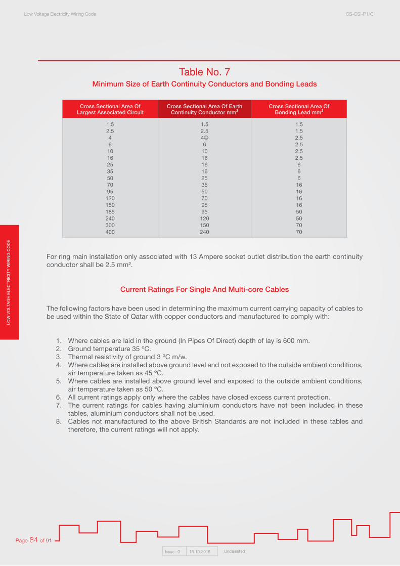
LOW
VO
LTA
GE
ELE
CT
RIC
ITY
WIR
ING
CO
DE
Low Voltage Electricity Wiring Code CS-CSI-P1/C1
Issue : 0 16-10-2016 Unclassified
Page 84 of 91
For ring main installation only associated with 13 Ampere socket outlet distribution the earth continuity conductor shall be 2.5 mm².
The following factors have been used in determining the maximum current carrying capacity of cables to be used within the State of Qatar with copper conductors and manufactured to comply with:
1. Where cables are laid in the ground (In Pipes Of Direct) depth of lay is 600 mm.2. Ground temperature 35 ºC.3. Thermal resistivity of ground 3 ºC m/w.4. Where cables are installed above ground level and not exposed to the outside ambient conditions,
air temperature taken as 45 ºC.5. Where cables are installed above ground level and exposed to the outside ambient conditions,
air temperature taken as 50 ºC.6. All current ratings apply only where the cables have closed excess current protection.7. The current ratings for cables having aluminium conductors have not been included in these
tables, aluminium conductors shall not be used.8. Cables not manufactured to the above British Standards are not included in these tables and
therefore, the current ratings will not apply.
Table No. 7Minimum Size of Earth Continuity Conductors and Bonding Leads
Current Ratings For Single And Multi-core Cables
Cross Sectional Area OfLargest Associated Circuit
Cross Sectional Area Of Earth Continuity Conductor mm²
Cross Sectional Area OfBonding Lead mm²
1.52.546
10162535507095
120150185240300400
1.52.54©6
10161616253550709595
120150240
1.51.52.52.52.52.5666
1616161650507070

LOW
VO
LTAG
E E
LEC
TR
ICIT
Y W
IRIN
G C
OD
ELow Voltage Electricity Wiring Code CS-CSI-P1/C1
Issue : 0 16-10-2016 Unclassified
Page 85 of 91
All cables to be of 600/1000 Volts grade. Solid conductors permitted only in the case of 1.5 mm² and 2.5 mm² cable.
Table No. 8
Table No. 9
Single Core PVC Insulated Cables in Conduit Or Trunkingat an Air Temperature of 45ºC
Two Core PVC Insulated, Steel Wire Armoured, PVC Sheathed
mm² 1.5 2.5 4 6 10 16 25 35 50 70 95 120 150 185 240 300 400
Current Rating Amperes
2 Cables Single Phase
14 19 25 33 44 60 80 100 114 150 182 205 250 277 350 402 486
Voltage Drop Per Ampere Per Meter
mV27 16 10 6.8 4.0 2.6 1.6 1.2 0.97 0.71 0.56 0.48 0.41 0.38 0.37 0.36 0.34
Current Rating Amperes 3 Or 4
Cables Three Phase12 17 23 30 41 53 70 90 100 140 170 200 215 250 300 350 407
Voltage Drop Per Ampere Per Meter
mV23 14 8.8 5.9 3.5 2.2 1.4 1.0 0.84 0.62 0.48 0.42 0.39 0.36 0.35 0.34 0.33
mm² 1.5 2.5 4 6 10 16 25 35 50 70 95 120 150 185 240 300 400
Voltage Drop Per Ampere Per Meter
mV28 17 11 4.1 4.0 2.6 1.6 1.2 0.97 0.71 0.56 0.48 0.41 0.38 0.37 0.36 0.34
Current Rating For Cable Laid Directly
In The Ground Amperes
18 24 31 39 51 66 84 104 121 150 176 200 222 252 300 325 360
Current Rating For Cable Run In
Underground Pipe Or Trench Amperes
18 24 30 37 50 65 83 100 119 143 172 200 220 250 240 320 360
Current Rating For Cable Run In Air Within A Building
Amperes
17 23 30 39 53 70 100 115 150 180 215 260 300 350 400 450 500
Current Rating For Cable Run In Air On Exterior Of A Building Or Part
ThereofAmperes
15 20 26 34 47 61 82 101 125 160 200 230 260 300 350 400 460
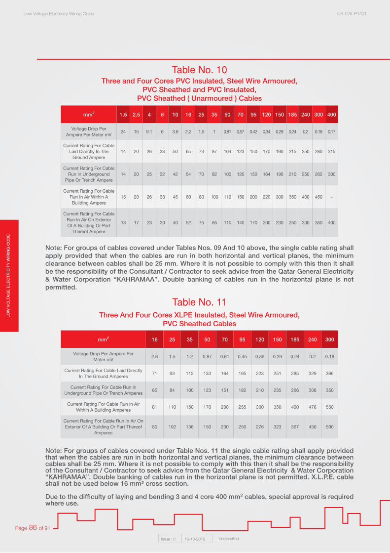
LOW
VO
LTA
GE
ELE
CT
RIC
ITY
WIR
ING
CO
DE
Low Voltage Electricity Wiring Code CS-CSI-P1/C1
Issue : 0 16-10-2016 Unclassified
Page 86 of 91
Note: For groups of cables covered under Tables Nos. 09 And 10 above, the single cable rating shall apply provided that when the cables are run in both horizontal and vertical planes, the minimum clearance between cables shall be 25 mm. Where it is not possible to comply with this then it shall be the responsibility of the Consultant / Contractor to seek advice from the Qatar General Electricity & Water Corporation “KAHRAMAA”. Double banking of cables run in the horizontal plane is not permitted.
Note: For groups of cables covered under Table Nos. 11 the single cable rating shall apply provided that when the cables are run in both horizontal and vertical planes, the minimum clearance between cables shall be 25 mm. Where it is not possible to comply with this then it shall be the responsibility of the Consultant / Contractor to seek advice from the Qatar General Electricity & Water Corporation “KAHRAMAA”. Double banking of cables run in the horizontal plane is not permitted. X.L.P.E. cable shall not be used below 16 mm² cross section.
Due to the difficulty of laying and bending 3 and 4 core 400 mm2 cables, special approval is required where use.
Table No. 10
Table No. 11
Three and Four Cores PVC Insulated, Steel Wire Armoured,PVC Sheathed and PVC Insulated,
PVC Sheathed ( Unarmoured ) Cables
Three And Four Cores XLPE Insulated, Steel Wire Armoured,PVC Sheathed Cables
mm² 1.5 2.5 4 6 10 16 25 35 50 70 95 120 150 185 240 300 400
Voltage Drop Per Ampere Per Meter mV
24 15 9.1 6 3.6 2.2 1.5 1 0.81 0.57 0.42 0.34 0.29 0.24 0.2 0.18 0.17
Current Rating For Cable Laid Directly In The
Ground Ampere14 20 26 33 50 65 73 87 104 123 150 170 190 215 250 280 315
Current Rating For Cable Run In Underground
Pipe Or Trench Ampere14 20 25 32 42 54 70 82 100 120 150 164 190 210 250 262 300
Current Rating For Cable Run In Air Within A Building Ampere
15 20 26 33 45 60 80 100 119 150 200 220 300 350 400 450 -
Current Rating For Cable Run In Air On Exterior Of A Building Or Part
Thereof Ampere
13 17 23 30 40 52 75 85 110 140 170 200 230 250 300 350 400
mm² 16 25 35 50 70 95 120 150 185 240 300
Voltage Drop Per Ampere PerMeter mV
2.6 1.5 1.2 0.87 0.61 0.45 0.36 0.29 0.24 0.2 0.18
Current Rating For Cable Laid Directly In The Ground Amperes
71 93 112 133 164 195 223 251 285 329 366
Current Rating For Cable Run In Underground Pipe Or Trench Amperes
65 84 100 123 151 182 210 235 266 308 350
Current Rating For Cable Run In Air Within A Building Amperes
81 110 150 170 208 255 300 350 400 476 550
Current Rating For Cable Run In Air On Exterior Of A Building Or Part Thereof
Amperes80 102 136 150 200 250 276 323 367 450 500

LOW
VO
LTAG
E E
LEC
TR
ICIT
Y W
IRIN
G C
OD
ELow Voltage Electricity Wiring Code CS-CSI-P1/C1
Issue : 0 16-10-2016 Unclassified
Page 87 of 91
Note: In case of one Three Phase circuit employing 4 Wires, no correctio factor is applicable and the ratings given in Tables Nos. 08, 09, 10, 11 shall be adopted. Where more than one Three Phase circuit is bunched in a conduit or trunking, then appropriate grouping factors shall be taken into consideration.
Note: Where spacing between adjacent cables exceeds twice their overall diameter, no reduction factor need to be applied.
Table No. 12
Table No. 14
Table No. 15
Table No. 13
MICC Cables Clipped Direct To A Non Metallic Surface
Correction Factors for Groups of More Than One Multi–Coreand Non–Armoured Cables
Correction Factors for Groups of More Than One Multi-Core and Non-Armoured Cables
Correction Factors for Groups of More Than Three Single Core Cables
mm² 1 1.5 2.5 4
2 Single Core Cable Or1 Two Core Cable Single Phase
Voltage Drop Per Ampere Per Meter mV 42 28 17 10
Current Rating CapacitiesAmperes 16 20 27 35
1 Four Core 3 CoreLoaded Three Phase
Voltage Drop Per Ampere Per Metre mV 36 24 14 9.1
Current Rating capacitiesAmperes 13 16 22 -
Type of Installation Method
Number of Conductors and Correction Factor
4 6 8 10 12 16 20 24 28 32 36 40
1,2,3,6 And 7 .8 .69 .62 .59 .55 .51 .48 .43 .41 .39 .38 .36
Type of Installation Method
Number of Conductors and Correction Factor
2 3 4 5 6 8 10 12 14 16 18 20
4,5,6 And 7 .8 .7 .65 .6 .57 .52 .48 .45 .43 .41 .39 .38
Type of Installation Method - 8
Number of Conductors and Correction Factor
2 3 4 5 6
Cables Laid Touching Each Other .81 .7 .7 .59 .55
Cables Laid 15 cm. Apart .87 .78 .74 .7 .68

LOW
VO
LTA
GE
ELE
CT
RIC
ITY
WIR
ING
CO
DE
Low Voltage Electricity Wiring Code CS-CSI-P1/C1
Issue : 0 16-10-2016 Unclassified
Page 88 of 91
Appendix No. 02 The Specifications of Electrical Service Cabinet
01 Introduction:
This specification covers the supply of metal waterproof cabinets required for the installation there in of energy meters and the “KAHRAMAA” incoming service, comprising electrical service cable, MCCB, earth and neutral terminals, and the customer’s cable.
02 Climatic Conditions:
The service electrical cabinet will be used in the following climatic conditions:• Maximum Direct Sunlight Temperature: 75oC• Maximum Ambient Air Temperature: 50oC• Maximum Relative Humidity: 100%• Occasional sandstorms with height salt content.• Occasional fog mixed with salty sea water mist.• Occasional torrential rain in winter and up to 15 cm per year. • Prolonged periods with temperatures between 30oC and 50oC with humidity simultaneously
between 30% and 100%.
03 Electrical Systems:
The electrical system to which the equipment installed in the cabinets will be connected will be nominally 250/433 Volts, 03 Phase, Star Connected and with Solid Neutral Earth.
04 Mounting Facilities:
The cabinets shall be suitable for mounting in a recess in the boundary wall of domestic premises, or on occasions directly inset into the wall of a building.
For this purpose the cabinet will have holes in the sides to permit the use of bolts or screws to secure it to the wall. At the front of the cabinet there shall be a lip intended to conceal irregularities in the gap between the wall and the cabinet.
05 Materials and Finish:
The cabinet shall be of Sheet Aluminium of a thickness sufficient to make the completed cabinet rigid and robust. The following is a guide to the finish to be used. It represents a minimum standard.
All ferrous surfaces and edges shall be cleaned of scale and rust by shot blasting and shall be treated on the same day, without outdoor exposure, with a zinc spray. The zinc chromate shall be applied by a flame gun process and shall be a thickness of ZN4 in accordance with BS 2569: (Specification ForSprayed Metal Coatings).
And BS 2569 - 2:1965 (1997) (Protection Of Iron And Steel Against Corrosion And Oxidation At Elevated Temperatures ). This treatment shall be followed by the application of one coat of zinc chromate base priming paint and an undercoat and a final coat of durable oil and weather resisting paint. The colour of the final coat shall be Light Aircraft Grey Code 627 of BS 381C : 1996 ( Specification For Colours For Identification, Coding And Special Purposes ), or of a similar colour. The paint shall have a matt finish.

LOW
VO
LTAG
E E
LEC
TR
ICIT
Y W
IRIN
G C
OD
ELow Voltage Electricity Wiring Code CS-CSI-P1/C1
Issue : 0 16-10-2016 Unclassified
Page 89 of 91
The inside of the cabinet shall have applied a coating of resin of GRP which shall cover the whole of the inside surface. This will be applied before the placing of the interior wood panel. Where an alternative finish specification is offered, the manufacturer shall bear in mind the need for the electrical service cabinet to provide long service in the arduous conditions stated above. It is essential that the finish shall be of the highest quality.
In the event that the electrical service cabinet is found to suffer from deterioration in service, Qatar General Electricity & Water Corporation “KAHRAMAA” reserve the right to reject the supplied and installed electrical service cabinet.
Where an alternative specification is offered, this shall be declared to Qatar General Electricity & Water Corporation “KAHRAMAA” at approval stage, and be subject to approval.
06 General Description:
The cabinet shall be of the shape and the dimensions as shown in the Sketch No. (14). It shall have a door at the front containing:
1. A clear wired glass window for reading the meter, no alternative to clear wired glass in acceptable.
2. A small door having on the outside a unique pattern lock, and on the inside a bolt, to allow access to the MCCB operating handle whilst preventing access to any live terminals. Two keys shall be for the unique lock. The door shall have a seal to prevent the ingress of water.
3. Weather rendering and weather proofing and vermin proof ventilation. Means shall be provided to prevent ingress of water through the main door and the small door. This shall generally be by a seal of neoprene or similar durable material.
4. Means of locking the main door which shall comprise two 8 mm triangular locks and a facility for fitting a padlock having a 7 mm hasp. The cabinet shall have mounted inside a plywood panel for the purpose of mounting the major electrical components of the installation.
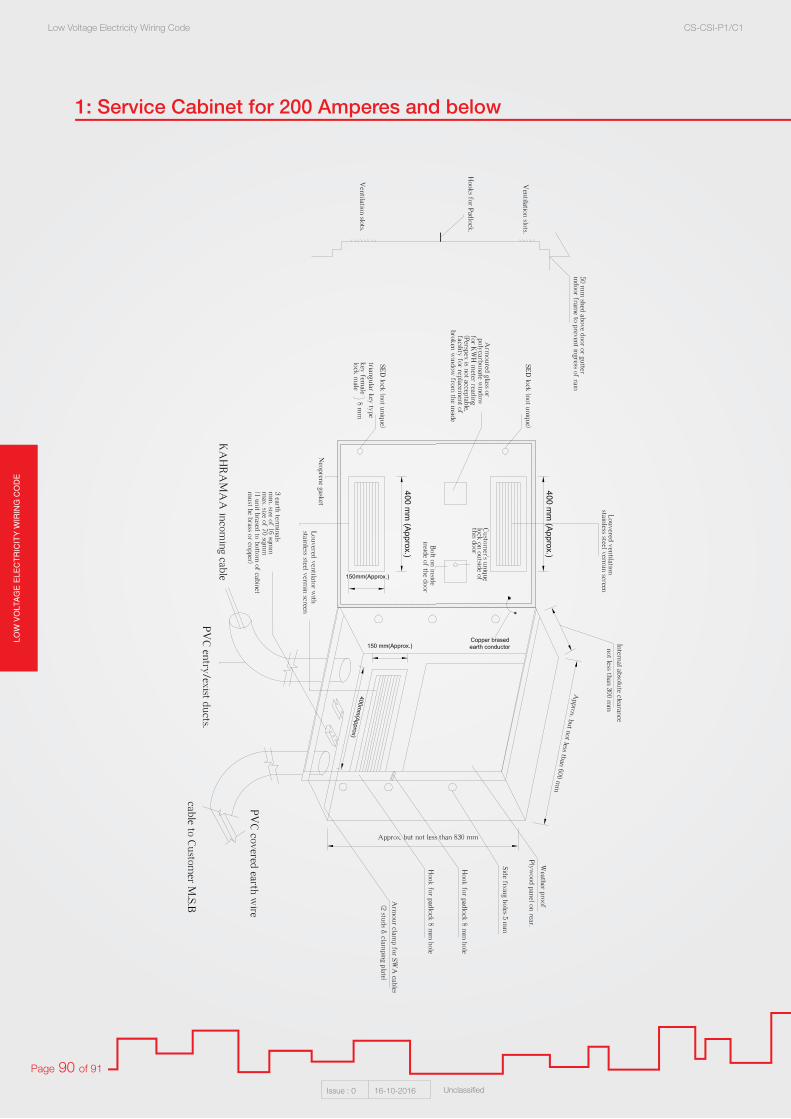
LOW
VO
LTA
GE
ELE
CT
RIC
ITY
WIR
ING
CO
DE
Low Voltage Electricity Wiring Code CS-CSI-P1/C1
Issue : 0 16-10-2016 Unclassified
Page 90 of 91
1: Service Cabinet for 200 Amperes and below

LOW
VO
LTAG
E E
LEC
TR
ICIT
Y W
IRIN
G C
OD
ELow Voltage Electricity Wiring Code CS-CSI-P1/C1
Issue : 0 16-10-2016 Unclassified
Page 91 of 91
2: Service Cabinet above 200 Amperes up to 350 Amperes
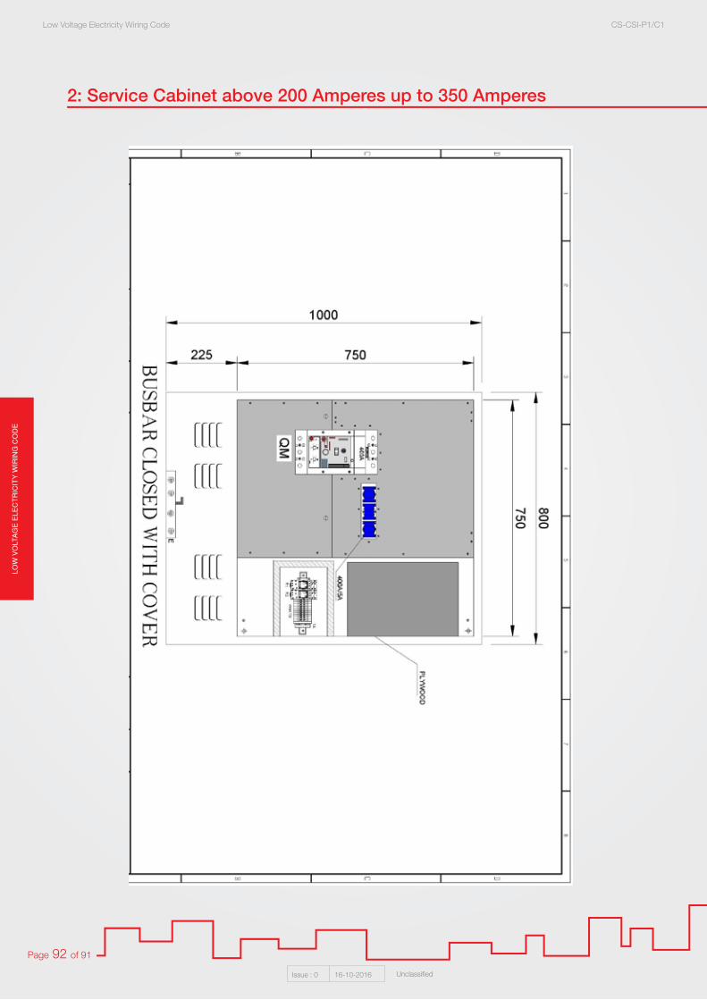
LOW
VO
LTA
GE
ELE
CT
RIC
ITY
WIR
ING
CO
DE
Low Voltage Electricity Wiring Code CS-CSI-P1/C1
Issue : 0 16-10-2016 Unclassified
Page 92 of 91
2: Service Cabinet above 200 Amperes up to 350 Amperes

LOW
VO
LTAG
E E
LEC
TR
ICIT
Y W
IRIN
G C
OD
ELow Voltage Electricity Wiring Code CS-CSI-P1/C1
Issue : 0 16-10-2016 Unclassified
Page 93 of 91
2: Service Cabinet above 200 Amperes up to 350 Amperes

LOW
VO
LTA
GE
ELE
CT
RIC
ITY
WIR
ING
CO
DE
Low Voltage Electricity Wiring Code CS-CSI-P1/C1
Issue : 0 16-10-2016 Unclassified
Page 94 of 91
2: Service Cabinet above 200 Amperes up to 350 Amperes

LOW
VO
LTAG
E E
LEC
TR
ICIT
Y W
IRIN
G C
OD
ELow Voltage Electricity Wiring Code CS-CSI-P1/C1
Issue : 0 16-10-2016 Unclassified
Page 95 of 91
2: Service Cabinet above 200 Amperes up to 350 Amperes
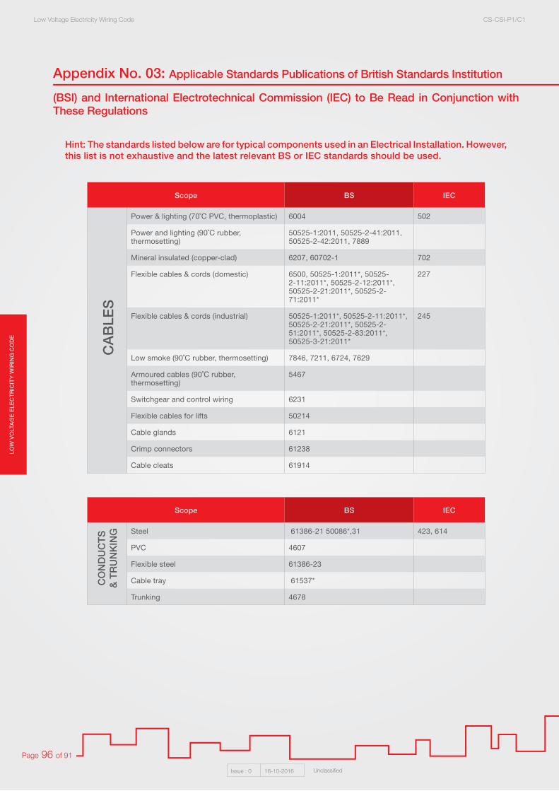
LOW
VO
LTA
GE
ELE
CT
RIC
ITY
WIR
ING
CO
DE
Low Voltage Electricity Wiring Code CS-CSI-P1/C1
Issue : 0 16-10-2016 Unclassified
Page 96 of 91
Appendix No. 03: Applicable Standards Publications of British Standards Institution
(BSI) and International Electrotechnical Commission (IEC) to Be Read in Conjunction with These Regulations
Hint: The standards listed below are for typical components used in an Electrical Installation. However, this list is not exhaustive and the latest relevant BS or IEC standards should be used.
Scope BS IEC
Steel 61386-21 50086*,31 423, 614
PVC 4607
Flexible steel 61386-23
Cable tray 61537*
Trunking 4678
Scope BS IEC
Power & lighting (70˚C PVC, thermoplastic) 6004 502
Power and lighting (90˚C rubber, thermosetting)
50525-1:2011, 50525-2-41:2011, 50525-2-42:2011, 7889
Mineral insulated (copper-clad) 6207, 60702-1 702
Flexible cables & cords (domestic) 6500, 50525-1:2011*, 50525-2-11:2011*, 50525-2-12:2011*, 50525-2-21:2011*, 50525-2-71:2011*
227
Flexible cables & cords (industrial) 50525-1:2011*, 50525-2-11:2011*, 50525-2-21:2011*, 50525-2-51:2011*, 50525-2-83:2011*, 50525-3-21:2011*
245
Low smoke (90˚C rubber, thermosetting) 7846, 7211, 6724, 7629
Armoured cables (90˚C rubber, thermosetting)
5467
Switchgear and control wiring 6231
Flexible cables for lifts 50214
Cable glands 6121
Crimp connectors 61238
Cable cleats 61914
CAB
LES
CO
ND
UC
TS&
TRU
NKI
NG
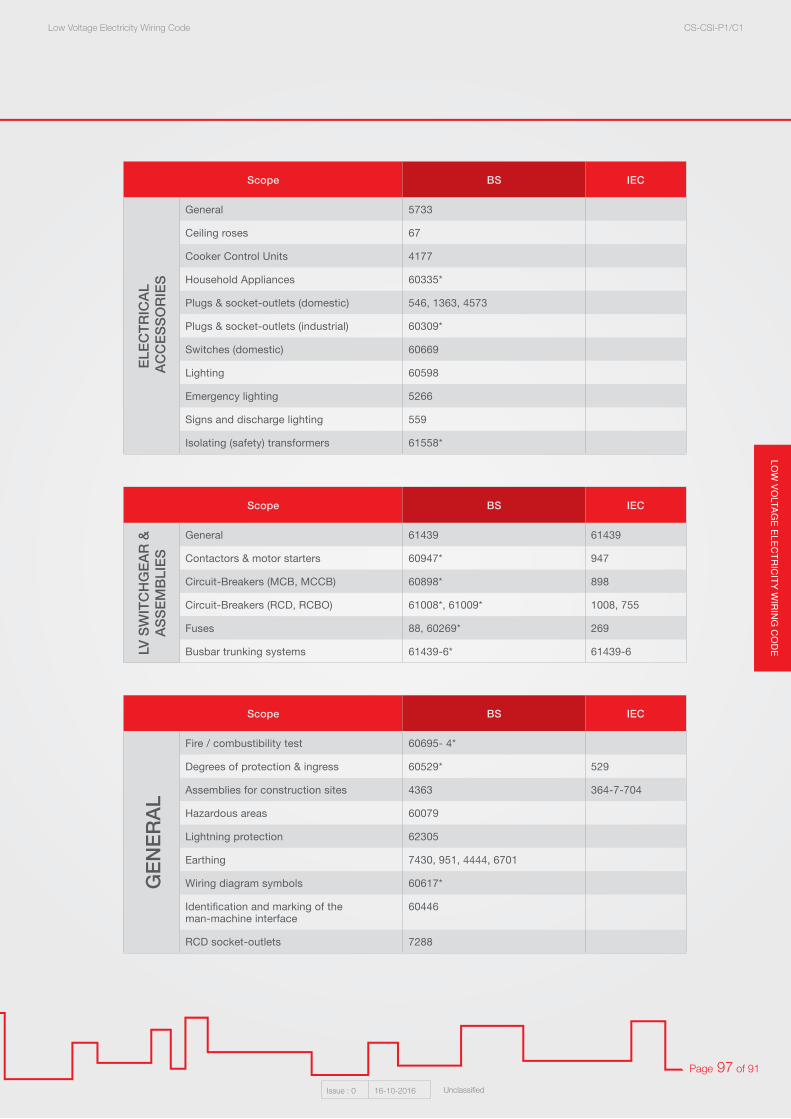
LOW
VO
LTAG
E E
LEC
TR
ICIT
Y W
IRIN
G C
OD
ELow Voltage Electricity Wiring Code CS-CSI-P1/C1
Issue : 0 16-10-2016 Unclassified
Page 97 of 91
Scope BS IEC
General 61439 61439
Contactors & motor starters 60947* 947
Circuit-Breakers (MCB, MCCB) 60898* 898
Circuit-Breakers (RCD, RCBO) 61008*, 61009* 1008, 755
Fuses 88, 60269* 269
Busbar trunking systems 61439-6* 61439-6
LV S
WIT
CH
GEA
R &
ASSE
MBL
IES
Scope BS IEC
General 5733
Ceiling roses 67
Cooker Control Units 4177
Household Appliances 60335*
Plugs & socket-outlets (domestic) 546, 1363, 4573
Plugs & socket-outlets (industrial) 60309*
Switches (domestic) 60669
Lighting 60598
Emergency lighting 5266
Signs and discharge lighting 559
Isolating (safety) transformers 61558*
ELEC
TRIC
AL A
CC
ESSO
RIES
Scope BS IEC
Fire / combustibility test 60695- 4*
Degrees of protection & ingress 60529* 529
Assemblies for construction sites 4363 364-7-704
Hazardous areas 60079
Lightning protection 62305
Earthing 7430, 951, 4444, 6701
Wiring diagram symbols 60617*
Identification and marking of theman-machine interface
60446
RCD socket-outlets 7288
GEN
ERAL