wm, husqvarna, k4000, 2018-06, power cutters
TRANSCRIPT

Workshop manual
K4000English
474 - 002 - 27.06.2018

Contents
1 Introduction1.1 Document description............................................ 31.2 Target group...........................................................31.3 Revisions................................................................31.4 Safety..................................................................... 31.5 Servicing tools........................................................3
2 Safety2.1 Safety definitions....................................................42.2 General safety instructions.....................................42.3 Symbols on the product......................................... 4
3 Servicing data3.1 Symbols in the diagrams........................................53.2 K4000 Wet/Cut-n-Break......................................... 63.3 K4000 Wet............................................................. 73.4 K4000 Wet............................................................. 83.5 K4000 Cut-n-Break ............................................... 93.6 K4000 Cut-n-Break.............................................. 103.7 K4000 Cut-n-Break.............................................. 11
4 Servicing tools4.1 Servicing tools overview.......................................12
5 Product overview for repair and servicing5.1 Components overview K4000Wetwet.................. 135.2 Components overview K4000Cut-n-Break...........145.3 Basic structure..................................................... 15
6 Repair and servicing6.1 Carbon brushes....................................................166.2 Carbon brush holders...........................................176.3 Circuit board.........................................................186.4 PRCD (Portable Residual Current Device).......... 186.5 Electrical cables................................................... 196.6 Rotor.................................................................... 216.7 Stator....................................................................226.8 Gear housing Wet................................................ 276.9 Gear housing Cut-n-Break................................... 336.10 Blade guard........................................................386.11 Cut-n-Break........................................................396.12 Water system..................................................... 446.13 Cables................................................................ 46
7 Diagrams7.1 Wiring diagram 230V............................................487.2 Wiring diagram 120V............................................497.3 Wiring diagram 120V UK and Ireland...................50
2 474 - 002 - 27.06.2018

1 Introduction1.1 Document descriptionThis manual gives a full description of how to domaintenance and repair on the product. It also givessafety instructions that the personnel must obey.
1.2 Target groupThis manual is for personnel with a general knowledgeof how to do repair and do servicing. All personnel thatdo repair or do servicing on the product must read andunderstand the manual.
1.3 RevisionsChanges to the product can cause changes to themaintenance work and spare parts. Separateinformation is sent out for each change.
Read the manual together with all received informationabout changes to maintenance and spare parts for theproduct.
1.4 SafetyWARNING: All personnel that repair or doservicing on the product must read andunderstand the safety instructions in thisworkshop manual.
1.5 Servicing toolsThe manual gives information about necessary servicingtools. Always use original tools from Husqvarna.
474 - 002 - 27.06.2018 Introduction - 3

2 Safety2.1 Safety definitionsThe definitions below give the level of severity for eachsignal word.
WARNING: Injury to persons.
CAUTION: Damage to the product.
Note: This information makes the product easier to use.
2.2 General safety instructions• You must not repair the product unless you have
read and understood this workshop manual.• The service center where the product is repaired
must have safety equipment approved by localbylaws.
• The product is examined and approved only with theequipment given or recommended by themanufacturer.
• Service personnel must make sure that the serviceand repairs in this manual are done following legalrequirements. This in order to avoid health andsafety risks of the personnel doing the work.
• When possible, disconnect the power cable andmake sure it cannot be connected until the service iscompleted.
• If you keep the product running during service, donot touch the wires. Electrical shock can causeinjury.
• Follow the local waste regulations.• Always make sure all nuts and bolts are correctly
tightened.• Do not lift the machine by holding the cable and do
not pull the plug by pulling the cable.• Check that the cables are not damaged and in good
condition.• Do not use the product if a cable is damaged.• Use protective gloves and eye protection. Goggles
must follow the ANSI Z87.1 for US or EN166 for EUcountries.
• When using compressed air, do not point it to yourbody. Air can go in to the blood stream.
• Wear ear protection when test running.• The product can make sparks and cause ignition of
flammable materials.• If a warning symbol decal on the product is
damaged or missing, replace the warning symboldecal.
2.3 Symbols on the productWARNING: Careless or incorrect use canresult in injury or death to the operator orothers.
Read the manual carefully and make sureyou understand the instructions beforeusing the product.
Always put on personal protectiveequipment:• Hearing protection• Protective goggles or a visor• Breathing mask.
This product in compliance with applicableEC directives.
WARNING! Dust from cutting can causebreathing problems. Use breathingprotection. Do not breathe exhaust fumes.Always make sure there is good airflow.
WARNING! Sparks from the cutting bladecan cause a fire in materials such as,gasoline, wood, fabric and dry grass.
WARNING! Kickbacks can be sudden,fast and can cause injuries. Read andunderstand the instructions in the manualbefore using the product.
Make sure the cutting disc is notdamaged.
WARNING! Do not use circular sawblades.
Note: Other symbols/decals on the product refer tospecial certification requirements for some markets.
4 - Safety 474 - 002 - 27.06.2018

3 Servicing data3.1 Symbols in the diagrams
Tightening torque
Grease
Thread lock
Torx
Allen
Bolt
Phillips
Pozidrive
Track
474 - 002 - 27.06.2018 Servicing data - 5

3.2 K4000 Wet/Cut-n-Break
1-1,2
T20
2.5-3
T27
1
2-2.5
T27
2
T27
T10
2
T27
3-4
T27
6.5-7
T272.5-3
T27
6.5-7
T27
6 - Servicing data 474 - 002 - 27.06.2018

3.3 K4000 Wet
6.5-7
T27
1
33-35
25-30
22
7
13
474 - 002 - 27.06.2018 Servicing data - 7

3.4 K4000 Wet
9-9.5
T27
2.5-3
T27
5-7
T27
2-3
T27
5-10
13
T27
8 - Servicing data 474 - 002 - 27.06.2018

3.5 K4000 Cut-n-Break
6.5-7
T27
10-12
T27
10-12
T27
1
7
13
33-35
474 - 002 - 27.06.2018 Servicing data - 9
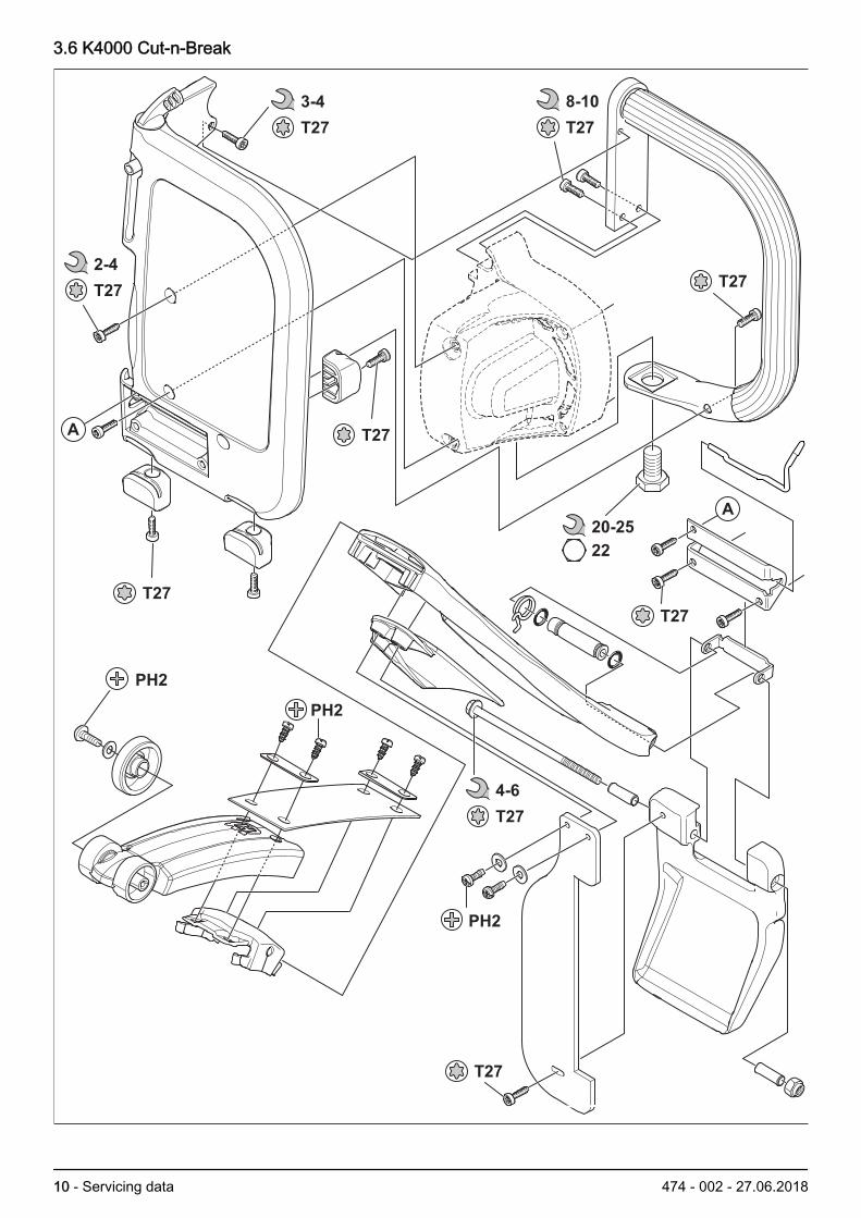
3.6 K4000 Cut-n-Break
A
A
20-25
22
2-4
T27
8-10
T27
T27
T27
T27
PH2
PH2
T27
T27
3-4
T27
4-6
T27
PH2
10 - Servicing data 474 - 002 - 27.06.2018

3.7 K4000 Cut-n-Break
10-15
25-30
7-10
T277-9
T27
2-3
PH2
PH2
13
13
474 - 002 - 27.06.2018 Servicing data - 11
4 Servicing tools
4.1 Servicing tools overview
1 2 3
8 9 10 11
4 5 6 7
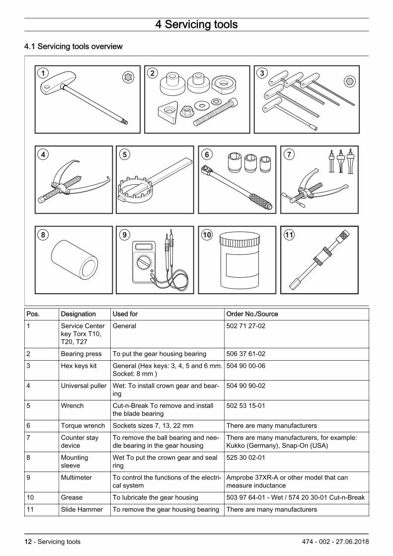
Pos. Designation Used for Order No./Source
1 Service Centerkey Torx T10,T20, T27
General 502 71 27-02
2 Bearing press To put the gear housing bearing 506 37 61-02
3 Hex keys kit General (Hex keys: 3, 4, 5 and 6 mm.Socket: 8 mm )
504 90 00-06
4 Universal puller Wet: To install crown gear and bear-ing
504 90 90-02
5 Wrench Cut-n-Break To remove and installthe blade bearing
502 53 15-01
6 Torque wrench Sockets sizes 7, 13, 22 mm There are many manufacturers
7 Counter staydevice
To remove the ball bearing and nee-dle bearing in the gear housing
There are many manufacturers, for example:Kukko (Germany), Snap-On (USA)
8 Mountingsleeve
Wet To put the crown gear and sealring
525 30 02-01
9 Multimeter To control the functions of the electri-cal system
Amprobe 37XR-A or other model that canmeasure inductance
10 Grease To lubricate the gear housing 503 97 64-01 - Wet / 574 20 30-01 Cut-n-Break
11 Slide Hammer To remove the gear housing bearing There are many manufacturers
12 - Servicing tools 474 - 002 - 27.06.2018

5 Product overview for repair and servicing
5.1 Components overview K4000Wetwet
11
10
9
1
2
3
4
5
6
8
7
1. Cutting blade (not supplied)2. Blade guard3. Spray nozzle on each side4. Front handle5. Inspection cover for carbon brushes6. Starter lock7. Rear handle
8. Circuit breaker9. Spindle lock10. Water coupling with valve11. PRCD (Portable Residual Current Device) (Not for
UK and Ireland)
474 - 002 - 27.06.2018 Product overview for repair andservicing - 13

5.2 Components overview K4000Cut-n-Break
1
4
5
2
2
3
6
7
8
11
9
10
12
13
14
1. Cutting blades (not supplied)2. Blade guard3. Spray guard4. Water valve5. Front handle6. Inspection cover for carbon brushes7. Starter lock8. Rear handle
9. Circuit breaker10. PRCD (Portable residual Current Device) (Not for
UK and Ireland)11. Water coupling12. Locknuts for belt adjustment13. Locknut for belt tensioner14. Belt tensioner
14 - Product overview for repair andservicing
474 - 002 - 27.06.2018

5.3 Basic structure
12
3
K4000Wet and Cut-n-Break have the same motor unitthat makes wet cutting possible with small quantities ofwater. The workshop manual has the same sections forthe motor and different sections for each type ofmachine.
1. Motor. The same unit for the two machines.Available for 230 V (220–240 V) and 120 V (100 -120 V).
2. Wet. Blade water coolant. Blade diameter 350 mm3. Cut-n-Break. Cutting unit with two blades. Blade
water coolant. Blade diameter 230 mm, cuttingdepth 400 mm.
474 - 002 - 27.06.2018 Product overview for repair andservicing - 15

6 Repair and servicing6.1 Carbon brushesThe carbon brushes transmit electric current to the rotor.The carbon brushes are wear parts and must beexamined regularly.
6.1.1 To examine the carbon brushesThe illustration shows a brush that is worn but can beused. The brush and the collector only have smallscratches in the direction of turning. The illustration alsoshows the results when the brush is worn. The spring nolonger gives the brush the correct pressure. Sparksoccurs which causes damage to the brushes and thecollector in a very short time. Sparks can also occur ifthe brushes cannot move. This can be because of dirt.Running in new brushes can also cause sparks.
1. Examine the brush using a Vernier caliper.
Replace the brushes when there is more than10mm/.4in between the brush holder and the top of thebrush.
>10 mm (.4”)
6.1.2 To remove the carbon brushes1. Remove the screws and the inspection cover.
2. Loosen the screw one turn and remove the cablelug.
3. Lift the spring and remove the carbon brush.
16 - Repair and servicing 474 - 002 - 27.06.2018

6.1.3 To install the carbon brushes1. Clean the holder.
2. Install the new carbon brushes.
3. Install the cable lug and tighten the screw.
4. Install the inspection cover and screws.
You must break in new carbon brushes. Run themachine for 30 minutes without a load.
6.2 Carbon brush holders
6.2.1 To remove the carbon brush holders1. Remove the brushes. See To remove the carbon
brushes on page 16
2. Remove the screws to the right handle.
3. Remove the right handle.
474 - 002 - 27.06.2018 Repair and servicing - 17

4. Remove the locking button and spring.
5. Remove the switch.
6. Remove the two screws for the left handle.
7. Remove the screw. Move the circuit board to theside.
8. Remove the screws.
9. Remove the carbon brush holders.
6.3 Circuit boardThe circuit board has two functions, Softstart andElgard™. Softstart gives a soft start with less current.Elgard™ gives a warning by changing the speed if thereis an overload.
6.3.1 To examine the circuit board1. To examine the circuit board, special equipment is
necessary. As an alternative you can use a processof exclusion. Examine the Power supply, cables,switches, stator and rotor. If they are operating, theproblem is with the circuit board. It must then bereplaced.
6.4 PRCD (Portable Residual Current Device)The current that comes in through the phase conductormust also go through the 0 conductor. The conductorsrun through a coil. If the same current goes in the twodirections, there will be no current in the coil. If there is a
18 - Repair and servicing 474 - 002 - 27.06.2018
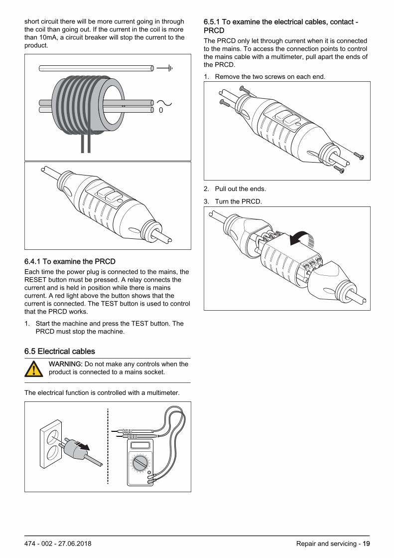
short circuit there will be more current going in throughthe coil than going out. If the current in the coil is morethan 10mA, a circuit breaker will stop the current to theproduct.
6.4.1 To examine the PRCDEach time the power plug is connected to the mains, theRESET button must be pressed. A relay connects thecurrent and is held in position while there is mainscurrent. A red light above the button shows that thecurrent is connected. The TEST button is used to controlthat the PRCD works.
1. Start the machine and press the TEST button. ThePRCD must stop the machine.
6.5 Electrical cablesWARNING: Do not make any controls when theproduct is connected to a mains socket.
The electrical function is controlled with a multimeter.
6.5.1 To examine the electrical cables, contact -PRCDThe PRCD only let through current when it is connectedto the mains. To access the connection points to controlthe mains cable with a multimeter, pull apart the ends ofthe PRCD.
1. Remove the two screws on each end.
2. Pull out the ends.
3. Turn the PRCD.
474 - 002 - 27.06.2018 Repair and servicing - 19

4. Measure between the contact pins, ground and therelated contact points on the PRCD.
6.5.2 To examine the electrical cables, contact -switchThe PRCD only let through current when it is connectedto the mains. To examinel the mains cable with amultimeter, pull apart the ends of the PRCD. Then youcan measure at the connection points.
1. Open the ends of the PRCD. See To examine theelectrical cables, contact - PRCD on page 19
2. Remove the switch. See To remove the carbonbrush holders on page 17
3. Divide the gear and motor housing See Todisassemble the gear housing on page 27
4. Measure between the contact pins and their contactpoints on the switch.
6.5.3 To examine the electrical cables, switch -motorThe cables from the switch to the motor goes throughthe circuit board. A probe from the multimeter cannot getin contact with a cable on the circuit board. The best is
20 - Repair and servicing 474 - 002 - 27.06.2018
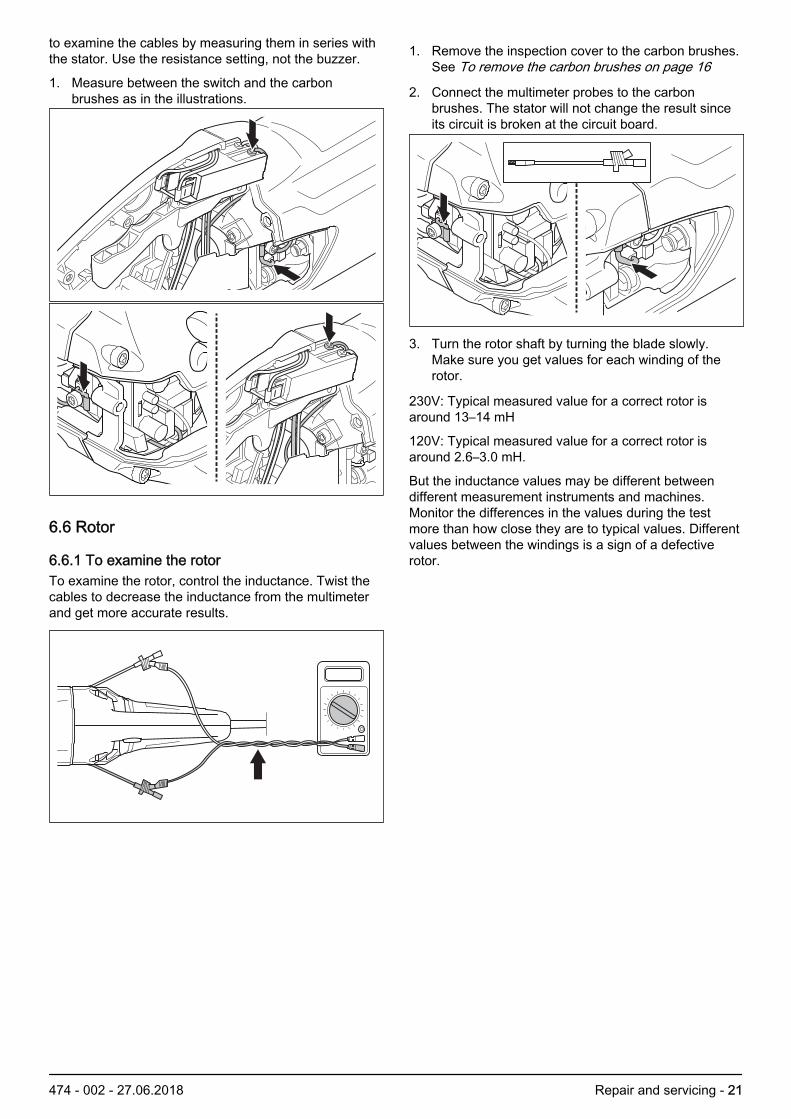
to examine the cables by measuring them in series withthe stator. Use the resistance setting, not the buzzer.
1. Measure between the switch and the carbonbrushes as in the illustrations.
6.6 Rotor
6.6.1 To examine the rotorTo examine the rotor, control the inductance. Twist thecables to decrease the inductance from the multimeterand get more accurate results.
1. Remove the inspection cover to the carbon brushes.See To remove the carbon brushes on page 16
2. Connect the multimeter probes to the carbonbrushes. The stator will not change the result sinceits circuit is broken at the circuit board.
3. Turn the rotor shaft by turning the blade slowly.Make sure you get values for each winding of therotor.
230V: Typical measured value for a correct rotor isaround 13–14 mH
120V: Typical measured value for a correct rotor isaround 2.6–3.0 mH.
But the inductance values may be different betweendifferent measurement instruments and machines.Monitor the differences in the values during the testmore than how close they are to typical values. Differentvalues between the windings is a sign of a defectiverotor.
474 - 002 - 27.06.2018 Repair and servicing - 21

6.6.2 To remove the rotorTo remove the rotor, see To disassemble the gearhousing on page 27.
6.6.3 To install the rotorTo install the rotor, please see To install the gearhousing on page 32.
6.7 Stator
6.7.1 To remove the stator1. Remove the screws to the right handle.
2. Remove the right handle.
3. Cut the cables from the circuit board to the stator atthe splices.
4. Move away the springs for the the brushes
5. Pull out the brushes.
6. Remove the screws for the gear set housing.
22 - Repair and servicing 474 - 002 - 27.06.2018

7. Open the gear housing with a screwdriver.
8. Remove the gear set housing
9. Remove the four screws to the gear housing.
10. Remove the screw for the ground wire.
11. Remove the gear housing and the rotor.
12. Remove the two screw holding the stator.
13. Remove the stator.
6.7.2 To examine the stator 230VTo examine the stator, you can measure resistance orinductance. A resistance test can show if the statorwinding is damaged. But it does not show if only somewindings have been short-ciruited. An inductance testcan show damages and short-ciruits. Twist the cables
474 - 002 - 27.06.2018 Repair and servicing - 23
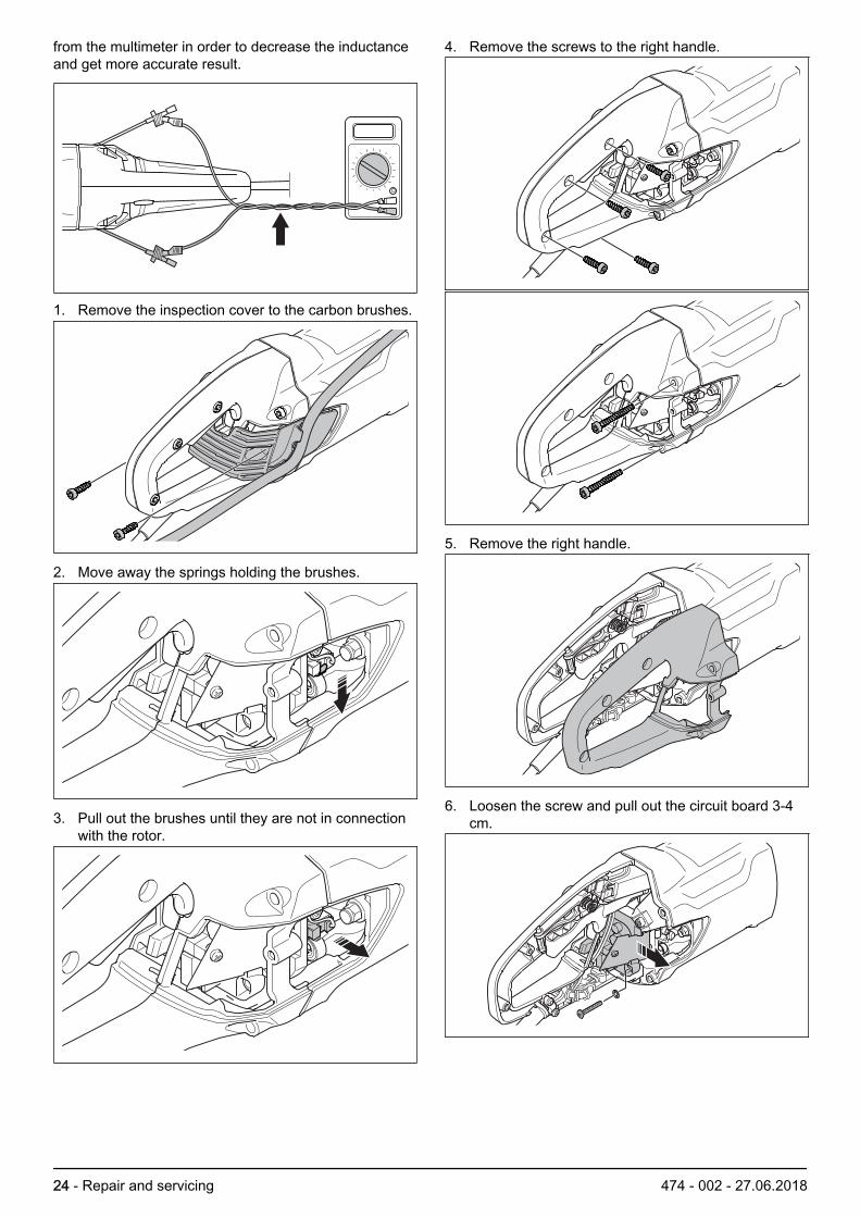
from the multimeter in order to decrease the inductanceand get more accurate result.
1. Remove the inspection cover to the carbon brushes.
2. Move away the springs holding the brushes.
3. Pull out the brushes until they are not in connectionwith the rotor.
4. Remove the screws to the right handle.
5. Remove the right handle.
6. Loosen the screw and pull out the circuit board 3-4cm.
24 - Repair and servicing 474 - 002 - 27.06.2018

7. Cut the two cables going to the stator at the splices.
8. With a barrier strip, connect the two cables going tothe stator.
9. Connect the multimeter probes to the cables of thecarbon brushes.
10. If you have disassembled the stator, measure thewindings one at a time. Connect the measurementcables to one of the cut off cable splices (A) and ringcable lugs (B) of one winding. Do the same on theother winding (A/B).
A
AB
B
When a test is made with the stator on the product, theinductance must be 40 mH. Resistance must be around8 Ω.
If the stator is broken, an inductance test gives 0 mH. Aresistance test gives a maximum value.
If some windings are short-circuited, the inductance willdecrease. If the value is 30% (30mH) below the typical,the stator must be replaced.
When a test is made on a disassembled stator, theinductance must be around 2.8 mH. Resistance valuesmust be around 0.4 Ω. Large differences between thewindings means the stator is defect.
6.7.3 To examine the stator 120VTo examine the stator, you can measure resistance orinductance. A resistance test can show if the statorwinding is damaged. But it does not show if only somewindings have been short-ciruited. An inductance testcan show damages and short-ciruits. Twist the cablesfrom the multimeter in order to decrease the inductanceand get more accurate result.
474 - 002 - 27.06.2018 Repair and servicing - 25

1. Remove the inspection cover to the carbon brushes.
2. Move away the springs holding the brushes.
3. Pull out the brushes until they are not in connectionwith the rotor.
4. Remove the screws to the right handle.
5. Remove the right handle.
6. Loosen the screw and pull out the circuit board 3-4cm.
26 - Repair and servicing 474 - 002 - 27.06.2018

7. Cut the cable going to the stator at the splice.
8. Connect one of the multimeter probes to the cablefor the carbon brush. Connect the other one to thecut off cable going to the stator.
9. A disassembled stator is best examined bymeasuring the stator and the windings one at a time.Connect one of the measurement cables to the graycable with a cut off splice (A). Connect the one toone of the two black cables for the circuit breaker(B). Do the same on the other black cable.
A
B
B
When a test is made with the stator on the product, theinductance must be 10-12 mH. Resistance must bearound 0.2-0.3 Ω.
If the stator is broken, an inductance test gives 0 mH. Aresistance test gives a maximum value.
If some windings are short-circuited, the inductance willdecrease. If the value is 30% (7 mH) below the typical,the stator must be replaced.
When a test is made on a disassembled stator, theinductance must be around 4–4.5 mH. Resistancevalues must be around 0.5–0.6 Ω. Large differencesbetween the windings means the stator is defect
6.8 Gear housing Wet
6.8.1 To disassemble the gear housing1. Remove the screws and the inspection cover.
2. Lift the springs for the brushes
3. Pull out the brushes.
474 - 002 - 27.06.2018 Repair and servicing - 27

4. Remove the screws for the gear set housing.
5. Open with a screwdriver.
6. Remove the gear set housing
7. Remove the four screws to the gear housing.
8. Remove the screw for the ground wire.
9. Remove the gear housing and the rotor.
10. If the rear bearing does not come out of the motorhousing, use a hammer and hit it lightly.
!
Note: Do not hit directly on the magnetic sensor.Use a socket as a sleeve and hit the socket. Orremove the sensor. When you put back the sensor,use threadlocker Loctite 243.
11. Remove the nut to the drive pinion.
!
28 - Repair and servicing 474 - 002 - 27.06.2018

Note: The nut must be loosened in a clockwisedirection.
12. Remove the drive pinion and the spacer.
13. Put the rotor in a vice with soft jaw guards.
14. Put a metal object against one corner of the gearhousing. Apply force as in the illustration. Use aplastic hammer on the opposite side. If necessary,change position of the metal object and use thehammer again on the opposite side.
6.8.2 To remove the gear housing bearingTo remove the gear housing, see To disassemble thegear housing on page 27. To disassemble the bearingyou must use an internal bearing extractor and a counterstay device. As an alternative to a counter stay device
you can use a slide hammer. Servicing tools overviewon page 121. Remove the circlip.
WARNING: There is a spring washer belowthe circlip. Use safety goggles!
2. Remove the bearing with a counter stay device or aslide hammer. If necessary, use a hot air gun aroundthe bearing to decrease the press force.
3. Remove the felt seal and the washers
6.8.3 To remove the crown gear and bearingInstructions how to remove the gear housing can befound in To disassemble the gear housing on page 27.
474 - 002 - 27.06.2018 Repair and servicing - 29

To remove the crown gear and bearing you must use auniversal puller. Servicing tools overview on page 121. Remove the crown gear with a universal puller.
2. Remove the crown gear bearing with a universalpuller.
6.8.4 To remove the gear cover bearingInstructions how to remove the gear housing can befound in To disassemble the gear housing on page 27.To remove the crown gear, see To remove the crowngear and bearing on page 29. To remove the bearing,use a counter stay device and an internal bearingextractor. As an alternative to the counter stay deviceyou can use a slide hammer. Servicing tools overviewon page 121. Remove the bearing in the cover with a counter stay
device.
6.8.5 To remove the crown gear from the shaft1. The crown gear and shaft are assembled in the
factory through shrink-fitting. It has a hard fit and canonly be removed with a hydralic press. To decreasethe press force, apply heat at the crown gear nearthe shaft.
6.8.6 To install the gear cover bearingTo install the gear cover bearing, use Husqvarnabearing press Servicing tools overview on page 12.
1. Add a large washer to help the nut. Pull the bearinginto position by turning the nut.
30 - Repair and servicing 474 - 002 - 27.06.2018
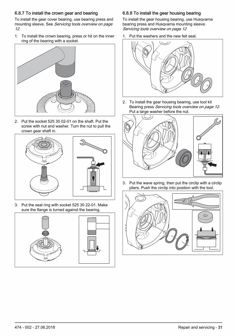
6.8.7 To install the crown gear and bearingTo install the gear cover bearing, use bearing press andmounting sleeve. See Servicing tools overview on page12.
1. To install the crown bearing, press or hit on the innerring of the bearing with a socket.
2. Put the socket 525 30 02-01 on the shaft. Put thescrew with nut and washer. Turn the nut to pull thecrown gear shaft in.
3. Put the seal ring with socket 525 30 22-01. Makesure the flange is turned against the bearing.
6.8.8 To install the gear housing bearingTo install the gear housing bearing, use Husqvarnabearing press and Husqvarna mounting sleeve. Servicing tools overview on page 121. Put the washers and the new felt seal.
2. To install the gear housing bearing, use tool kitBearing press Servicing tools overview on page 12.Put a large washer before the nut.
3. Put the wave spring, then put the circlip with a circlippliers. Push the circlip into position with the tool.
474 - 002 - 27.06.2018 Repair and servicing - 31

6.8.9 To install the gear housing1. Push the rotor in to the gear housing.
2. Push the spacer and the drive pinion onto the shaft.
3. Tighten the nut.
!
Note: The nut must be tightened in ancounterclockwise direction. The tightening torquemust be 33-35 Nm. Use an open end torque wrench
4. Put the gear housing and the rotor half into themotor housing.
5. Tighten the screw for the ground wire from the motorhousing.
6. Put the gear housing and rotor.
7. Tighten the four screws to the gear housing.
32 - Repair and servicing 474 - 002 - 27.06.2018

8. To apply grease, use Husqvarna grease. See Servicing tools overview on page 12. It has thecorrect type and quantity of grease. You can alsoapply 100g of Eco 100gr Bevel gear grease orequivalent. Make sure there is grease on the drivepinion and bearing.
9. Put the gear set housing and new gasket.
10. Tighten the four screws with a torque of 10-12 Nm.
6.9 Gear housing Cut-n-Break
6.9.1 To disassemble the gear housingNote: The crown gear unit cannot be disassembled. Theunit must be replaced. When you replace the crown gearunit, replace the drive pinion at the same time.
1. Remove the screws and the inspection cover.
2. Lift the springs that hold the brushes.
3. Pull out the brushes.
474 - 002 - 27.06.2018 Repair and servicing - 33

4. Remove the screws for the crown gear unit.
5. Open with a screwdriver.
6. Remove the crown gear unit.
7. Remove the four screws to the gear housing.
8. Remove the screw for the ground wire.
9. Remove the gear housing and the rotor.
10. If the rear bearing does not come out of the motorhousing, use a hammer and hit it lightly.
!
Note: Do not hit directly on the magnetic sensor.Use a socket as a sleeve and hit the socket. Orremove the sensor. When putting back the sensor,use threadlocker Loctite 243.
11. Remove the nut to the drive pinion.
!
34 - Repair and servicing 474 - 002 - 27.06.2018

Note: The nut must be loosened in a clockwisedirection.
12. Remove the drive pinion and the spacer.
13. Put the rotor in a vice with soft jaw guards.
14. Put a metal object against one corner of the gearhousing. Apply force as in the illustration. Use aplastic hammer on the opposite side. If necessary,change position of the metal object and use thehammer again on the opposite side.
6.9.2 To remove the gear housing bearingTo remove the gear housing, see To disassemble thegear housing on page 33. To remove the bearing, use acounter stay device and an internal bearing extractor. As
an alternative to the counter stay device you can use aslide hammer.Servicing tools overview on page 121. Remove the circlip.
2. Remove the bearing with a counter stay device or aslide hammer. If necessary, use a hot air gun aroundthe bearing to decrease the press force.
3. Remove the felt seal and the washers.
474 - 002 - 27.06.2018 Repair and servicing - 35

6.9.3 To remove the gear housing needle bearing1. Remove the bearing with a counter stay device. If
necessary, use a hot air gun below the bearing seatto decrease the press force.
6.9.4 To install the gear housing needle bearing1. Make an assembly tool as in the illustration. Put tape
or shrink tubing on the threads.
2. Turn the flat side of the bearing with the text up,against the nut.
3. Apply heat to the bearing seat with a hot air gun, toaround 100 °C (200 °F) and cool the bearing withcoolant spray. Hit the assembly tool with a heavyand soft mallet until the bearing is level with the topedge of the bearing seat.
6.9.5 To install the gear housing bearingTo install the gear housing bearing, use Husqvarnabearing press and Husqvarna mounting sleeve.SeeServicing tools overview on page 121. Put the washers and the new felt seal in the cavity
for the bearing.
2. To install the gear housing bearing, use the bearingpress . Put a large washer before the nut.
3. Put the circlip with a circlip pliers. Push the circlipinto position with the tool.
36 - Repair and servicing 474 - 002 - 27.06.2018

6.9.6 To install the gear housing1. Push the rotor in to the gear housing.
2. Push the spacer and the drive pinion onto the shaft.
3. Tighten the nut.
!
Note: The nut must be tightened in ancounterclockwise direction. The tightening torquemust be 33-35 Nm. Use a torque wrench with a u-grip since there is not space for a socket.
4. Put the gear housing and the rotor half into themotor housing.
5. Tighten the screw for the ground wire from the motorhousing.
6. Put the gear housing and rotor.
7. Tighten the four screws to the gear housing.
474 - 002 - 27.06.2018 Repair and servicing - 37

8. To apply grease, use Husqvarna grease, 25g. See Servicing tools overview on page 12. Do not useother types of grease. Apply it to the drive pinion andfill the needle bearing.
9. Put the crown gear unit and new gasket.
10. Tighten the four screws with a torque of 10-12 Nm.
6.10 Blade guard
6.10.1 To remove the blade guard1. Remove the center bolt, washers, spacer and plastic
seal.
2. Remove the screws and the washer that hold theblade guard against the bearing housing.
38 - Repair and servicing 474 - 002 - 27.06.2018
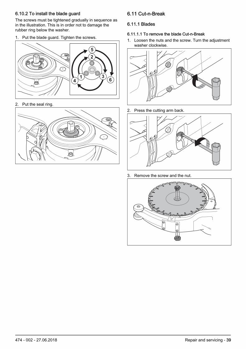
6.10.2 To install the blade guardThe screws must be tightened gradually in sequence asin the illustration. This is in order not to damage therubber ring below the washer.
1. Put the blade guard. Tighten the screws.
14
2
5
36
2. Put the seal ring.
6.11 Cut-n-Break
6.11.1 Blades
6.11.1.1 To remove the blade Cut-n-Break1. Loosen the nuts and the screw. Turn the adjustment
washer clockwise.
2. Press the cutting arm back.
3. Remove the screw and the nut.
474 - 002 - 27.06.2018 Repair and servicing - 39

6.11.1.2 To install the blade Cut-n-Break1. Push the belt out from the center of the blade.
2. Put one blade with the nut below the cutter bar. Putthe other blade with the screw on top.
3. To prevent the belt getting blocked between theblades, tighten the center screw a bit then rotate theblade. Do this again until the blade is fully tightened.
6.11.2 Belt
6.11.2.1 To tighten the belt Cut-n-Break1. Loosen the nuts that hold the cutting arm and the
screw that locks the adjustment washer.
2. Turn the adjustment washer to a point where the beltcan be pressed down 5mm (3/16in)with ascrewdriver.
X
3. Tighten the adjustment screw.
40 - Repair and servicing 474 - 002 - 27.06.2018

6.11.2.2 To remove the belt Cut-n-Break1. Remove rubber guard from the screw.
2. Move the spray guard to the side.
3. Remove the screws and nuts.
4. Remove the plates.
5. Lock the nut and remove the center screw. Removethe pulley wheel and the belt.
6.11.2.3 To install the belt Cut-n-Break1. Put the cutting arm temporary with the two nuts.
2. Put the belt.
474 - 002 - 27.06.2018 Repair and servicing - 41

3. Put the front guard.
4. Put the pulley wheel.
5. Put the rear belt guard.
6.11.3 Bearing
6.11.3.1 To remove the bearing Cut-n-BreakTo remove the bearing, use Husqvarna wrench. See Servicing tools overview on page 121. Remove the belt guard.
2. Put it in a vice.
3. Remove the bearing cage with the Husqvarnawrench
42 - Repair and servicing 474 - 002 - 27.06.2018
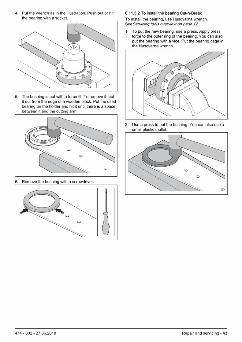
4. Put the wrench as in the illustration. Push out or hitthe bearing with a socket.
5. The bushing is put with a force fit. To remove it, putit out from the edge of a wooden block. Put the usedbearing on the holder and hit it until there is a spacebetween it and the cutting arm.
6. Remove the bushing with a screwdriver.
6.11.3.2 To install the bearing Cut-n-BreakTo install the bearing, use Husqvarna wrench.SeeServicing tools overview on page 121. To put the new bearing, use a press. Apply press
force to the outer ring of the bearing. You can alsoput the bearing with a vice. Put the bearing cage inthe Husqvarna wrench.
2. Use a press to put the bushing. You can also use asmall plastic mallet.
474 - 002 - 27.06.2018 Repair and servicing - 43

6.11.4 Cutting unit Cut-n-Break
6.11.4.1 To remove the cutting unitThe cutting unit can be disassembled to make repairseasier. For example if you are repairing the gearhousing or if you are dividing the motor.
1. Remove the belt tensioner and the belt guard nuts.
2. Lock the nut and remove the center screw. Removethe nut and pulley wheel.
3. Remove the hose connector from the water valveand remove the cutting unit.
4. Remove the screws on the spray guard, on thehandle and at the bottom of the gear housing.
5. Remove the cutting unit.
6.12 Water system
44 - Repair and servicing 474 - 002 - 27.06.2018

6.12.1 Water couplingThe water coupling is adapted to the Gardena® system.The flow control adjusts a constant and low flow whenthe water pressure changes. A filter in the watercoupling prevents particles of dirt to stop the flow. Thewater flow is stopped by the valve on the hose.
6.12.2 To remove the water filter1. Remove the water filter with a wood screw.
6.12.3 Flow controlThe flow control is made of a rubber cylinder with a holefor the water. The hole changes dimension with thepressure of the water coming in. The flow control is atthe water valve.
1. The side with a mark and text must be turned to theside where the water is coming in.
6.12.4 Hose clipsThe hose clip can be used again after it has beenremoved.
1. Open the hose clip with a screwdriver.
2. Close the hose clip using pliers.
6.12.5 To remove the spray nozzle - WetThe spray nozzles are on each side of the blade guard.The water hits the blade near the center. The outwardmoving force moves it out in the direction of the edge ofthe blade. The spray nozzles have a smaller diametercompared to the gasoline cutters in order to limit thequantity of water.
1. Lock the spray nozzle with a 15mm wrench.Remove the screw.
6.12.6 To remove the spray nozzle Cut-n-BreakThe spray nozzle is in the blade guard. The water hitsthe blades near the center. The outward moving forcemoves the water to the edges of the blades. The spray
474 - 002 - 27.06.2018 Repair and servicing - 45

nozzle has a smaller diameter compared to the gasolinecutters in order to limit the quantity of water.
1. To remove the spray nozzle, the belt guards mustfirst be removed. SeeTo remove the belt Cut-n-Break on page 41
6.13 Cables
6.13.1 To remove cables from the terminal barThe terminal bar is used to connect the ground wires. Itmust not be used again if cables have been removedfrom it. The terminal bar has a sealing gel whichprevents moisture get through to the contact surfaces.
1. Break up the contact strip with a screwdriver.
2. Pull out all cables. The cables must be cut byapprox. 5 mm in order to make new contact surfacesfor the contact strip
6.13.2 To put cables into the terminal bar1. Put the cables all the way to the bottom of the
terminal bar. Note that the cables must not bestripped.
2. Push together the splice sleeve using a pair ofpliers. Pull the cables to make sure they are lockedagainst the splice sleeve.
6.13.3 To remove splicesMoisture proof splice sleeves are installed on the cablesfrom the circuit board to the stator. It is necessary to cutthe splice points if you must change the stator or circuitboard.
1. Cut the cable by approx. 7 mm from the outer endsof the splice sleeve.
2. Strip the two parts of the sleeve and cable at thesame time.
XX
46 - Repair and servicing 474 - 002 - 27.06.2018

6.13.4 To install splices and sleeves1. Remove the cable insulation by approx. 7 mm at the
two ends of the cable. Put the cables in the splicesleeve.
2. Push together the splice sleeve with a pliers forcable clips. Pull the cables to make sure they arelocked against the splice sleeve.
3. The splice sleeve is put with hot melt sealant andthe casing shrinks when hot. Use a hot air gun,approx. 150 °C (300 °F). Apply heat until the casingcloses tightly around the cable and some sealant iscoming out.
474 - 002 - 27.06.2018 Repair and servicing - 47

7 Diagrams
7.1 Wiring diagram 230V
3 5
6
78
12
9
9
10
10
11
12
413
14
1 3 54 6 7 8
10
11
13
12
14
2
9
1. To mains plug2. Live cables3. Emc filter4. Emc filter5. Ground cable: mains input - terminal bar6. Ground cable: terminal bar - circuit board7. Ground cable: terminal bar - front of machine8. Terminal bar9. Live cables: circuit board - stator10. Live cables: stator - rotor11. Ground point front of machine12. Live cables: toroid filter - circuit breaker13. Live cables: circuit breaker - circuit board
48 - Diagrams 474 - 002 - 27.06.2018

7.2 Wiring diagram 120V
1
3
4
7
8
10
9
11
2
6
5
1 3
5
7
8
10
9
11
2
6
4
1. To mains plug2. Live cables3. Ground cable: mains input - terminal bar4. Terminal bar5. Ground cable: terminal bar - front of machine6. Live cable: circuit board - stator7. Live cable: stator - rotor8. Ground point front of machine9. Live cables: circuit breaker - circuit board
474 - 002 - 27.06.2018 Diagrams - 49

7.3 Wiring diagram 120V UK and Ireland
1
4
6
8
9
11
10
12
2
7
5
3
1 3 4
6
8
9
11
10
12
2
7
5
1. To mains plug2. Live cables3. Emc filter4. Ground cable: mains input - terminal bar5. Terminal bar6. Ground cable: terminal bar - front of machine7. Live cable: circuit board - stator8. Live cable: stator - rotor9. Ground point front of machine10. Live cables: circuit breaker - circuit board
50 - Diagrams 474 - 002 - 27.06.2018

474 - 002 - 27.06.2018 Diagrams - 51

596432402
2018-06-27