working-fluid selection and performance investigation of a
TRANSCRIPT

Applied Energy 186 (2017) 376–395
Contents lists available at ScienceDirect
Applied Energy
journal homepage: www.elsevier .com/ locate/apenergy
Working-fluid selection and performance investigation of a two-phasesingle-reciprocating-piston heat-conversion engine
http://dx.doi.org/10.1016/j.apenergy.2016.05.0080306-2619/� 2016 The Authors. Published by Elsevier Ltd.This is an open access article under the CC BY license (http://creativecommons.org/licenses/by/4.0/).
⇑ Corresponding author.E-mail address: [email protected] (C.N. Markides).
Oyeniyi A. Oyewunmi a, Christoph J.W. Kirmse a, Andrew J. Haslamb, Erich A. Müller b,Christos N. Markides a,⇑aClean Energy Processes (CEP) Laboratory, Department of Chemical Engineering, Imperial College London, South Kensington Campus, London SW7 2AZ, United KingdombMolecular Systems Engineering (MSE), Centre for Process Systems Engineering (CPSE), Department of Chemical Engineering, Imperial College London, South KensingtonCampus, London SW7 2AZ, United Kingdom
h i g h l i g h t s
� A dynamic model of the Up-THERM two-phase thermofluidic oscillator heat converter is presented.� The working-fluid saturation pressure and vapour-phase density are important in describing the engine’s performance.� Water and forty-five organic working-fluids are considered in a pre-specified Up-THERM design with a heat source at 360 �C.� R113 and i-hexane are identified as optimal working fluids in terms of maximizing the engine’s power output.� Ammonia, R245ca and butane are attractive working fluids over a wider range of heat-source temperatures.
a r t i c l e i n f o
Article history:Received 20 January 2016Received in revised form 28 April 2016Accepted 1 May 2016Available online 20 June 2016
Keywords:Unsteady heat-enginePrime moverWaste-heat recoveryRenewable-heat conversionCombined heat and powerOff-grid power generation
a b s t r a c t
We employ a validated first-order lumped dynamic model of the Up-THERM heat converter, a two-phaseunsteady heat-engine that belongs to a class of innovative devices known as thermofluidic oscillators,which contain fewer moving parts than conventional engines and represent an attractive alternativefor remote or off-grid power generation as well as waste-heat conversion applications. We investigatethe performance of the Up-THERM with respect to working-fluid selection for its prospective applica-tions. An examination of relevant working-fluid thermodynamic properties reveals that the saturationpressure and vapour-phase density of the fluid play important roles in determining the performance ofthe Up-THERM – the device delivers a higher power output at high saturation pressures and has higherexergy efficiencies at low vapour-phase densities. Furthermore, working fluids with low critical temper-atures, high critical pressures and exhibiting high values of reduced pressures and temperatures result indesigns with high power outputs. For a pre-specified Up-THERM design corresponding to a target (CHPprime-mover) application with a heat-source temperature of 360 �C, water is compared with 45 otherpure working fluids. When maximizing the power output, R113 is identified as the optimal fluid, followedby i-hexane. Fluids such as siloxanes and heavier hydrocarbons are found to maximize the exergy andthermal efficiencies. The ability of the Up-THERM to convert heat over a range of heat-source tempera-tures is also investigated, and it is found that the device can deliver in excess of 10 kW when utilizingthermal energy at temperatures above 200 �C. Of all the working fluids considered here, ammonia,R245ca, R32, propene and butane feature prominently as optimal and versatile fluids delivering highpower over a wide range of heat-source temperatures.� 2016 The Authors. Published by Elsevier Ltd. This is an openaccess article under the CCBY license (http://
creativecommons.org/licenses/by/4.0/).
1. Introduction the price of oil, energy prices have been generally rising over the
Recent trends in global energy use have shown that energy con-sumption has been increasing, especially amongst developingcountries, while, with the exception of the very recent drop in
past decades due to a combination of factors, including the grow-ing demand for energy and the gradual reduction in the availablereserves of readily accessible fossil fuels [1]. The desire for secure,sustainable, reliable and affordable energy provision in light ofincreasing energy costs and dwindling resources, along withconcerns related to the adverse effects on human health and theenvironment caused by the release into the atmosphere of gases
Nomenclature
A cross-sectional area ðm2ÞC capacitance ðm4 s2 kg�1Þc geometrical constant (–)d diameter (m)F heat transfer coefficient correlation function (–)f frequency (Hz)g gravitational acceleration ðm s�2ÞH Heaviside step-function (–)h height (m)h heat transfer coefficient ðWm�2 K�1Þhfg enthalpy change during vaporization ðJ kg�1Þk spring constant ðNm�1ÞL inductance ðkg m�4Þl length (m)m mass (kg)P; p pressure (Pa)P ¼ _W power output (W)_Q heat flow-rate (W)R resistance ðkg m�4 s�1Þsfg entropy change during vaporization ðJ kg�1 K�1Þ_S rate of entropy generation ðWK�1ÞT temperature (�C, K)t time (s)U flow rate ðm3 s�1Þv fg volume change during vaporization ðm3 kg�1ÞV volume ðm3Þy spatial coordinate (–)
Greek lettersa temperature amplitude (K)b temperature spatial-gradient parameter (m�1)c heat capacity ratio (–)d gap between piston and slide bearing (m)� gap between shaft and motor (m)g efficiency (–)K non-dimensional expression for b (–)l dynamic viscosity (Pa s)q density ðkg m�3Þ
Subscripts‘0’ equilibrium‘acc’ accumulator‘b, l’ slide-bearing liquid‘b, p’ slide-bearing piston‘c’ connection tube‘c’ critical thermodynamic property‘cold’ cold heat-exchanger‘cv’ check valve‘d’ displacer cylinder‘eq’ equilibrium‘ex’ exergy‘g’ gas volume, saturated vapour-phase‘gen’ generator‘gs’ gas spring‘hm’ hydraulic motor‘hot’ hot heat-exchanger‘hs’ heat source‘hx’ heat exchanger‘l’ liquid volume, saturated liquid-phase‘l, d’ liquid height in the displacer cylinder‘load’ load‘lub’ lubricant‘max’ maximum‘min’ minimum‘ms’ mechanical spring‘nl’ non-linear‘pist’ piston‘pv’ piston valve‘q’ heat flux‘r’ reduced thermodynamic property‘sat’ saturation thermodynamic property‘sink’ heat sink‘t’ pipe in load‘th’ thermal domain‘v’ vapour volume‘w’ wall‘wf’ working fluid
O.A. Oyewunmi et al. / Applied Energy 186 (2017) 376–395 377
produced from the combustion of fossil fuels, have led to an accel-eration of efforts aimed at developing alternative, renewableenergy sources, including sources of renewable heat such as solar,geothermal, and (arguably) biomass/biogas [1,2].
In addition, a vast amount of low- to medium-grade (i.e.,temperature) ‘wasted’ thermal energy, which is mainly availableat significantly lower temperatures than those associated withfossil-fuel combustion (often below 300 �C), is rejected to theenvironment in the form of exhaust gases, cooling streams, etc.This energy resource arises from a diverse and broad range ofsources in the domestic, commercial, industrial and transport sec-tors. Recent estimates indicate that over 60% of the overall primaryenergy supplied globally is rejected in this form; e.g., 59.0 Quads(62� 1018 J) of thermal energy was rejected in the US in 2013,which is in excess of the actual national energy consumption(38.4 Quads) by over 50% [3]. Similar figures are reported forEurope and Asia. Therefore, a key component of the energysolution, beyond expanding the utilization of renewable andsustainable energy sources, involves increasing the overallefficiency of fossil-fuel use, thereby reducing both the demandfor fossil fuels and the associated emissions. The recovery andre-use of heat has thus been identified as a major pathway towardsa high-efficiency and sustainable energy future [1].
Engines capable of utilizing fluid streams at lower temperaturesare expected to be inherently inefficient; the Chambadal–Novikovefficiency, gC—N ¼ 1� ffiffiffiffiffiffiffiffiffiffiffiffiffiffiffiffiffiffi
Tsink=Ths
p[4,5], for heat-source tempera-
tures below 300 �C drops below 30%, and at heat-source tempera-tures of 100 �C, it is close to 10%. Despite these low efficiencies,the development and utilization of such engines represents aninteresting economic proposition since these would provide ameans of reducing the rate at which non-renewable energyresources are being depleted, as well as mitigating any environ-mental (human or natural) impact associated with the use of theseresources. For example, we estimate that recovering and re-usingwaste-heat streams has the potential to provide an additional 8 EJof energy towards the annual energy consumption in Europe,thereby reducing the annual primary-energy use by over 15%. Thiswouldmanifest as a direct reduction of the rate at which fossil fuelsare being consumed and at which associated emissions are beingproduced. This example highlights the important opportunities thatexist for suitable technologies that can be deployed for heat recov-ery, re-use and energy integration, e.g., by conversion to usefulmechanical, hydraulic or electrical work. In plants that are alreadyin operation the implementation of various waste-heat recoverytechnologies can lead to important boosts in overall efficiencyand utility expenditure savings [6], and in newly built facilities that

Fig. 1. Schematic of the Up-THERM heat engine with hot and cold heat exchangers,piston, valve, mechanical springs and hydraulic motor with piston at the top deadcentre (TDC) and at the bottom dead centre (BDC, inset). The top space of thehydraulic accumulators is filled with air.
378 O.A. Oyewunmi et al. / Applied Energy 186 (2017) 376–395
incorporate the most up-to-date technologies these savings canpotentially be even higher according to theoretical predictions.
In summary, a number of challenges and opportunities continueto act as important drivers behind a strong interest in the utiliza-tion of renewable heat and in the recovery and re-utilization ofwaste heat. The development of high-performance and affordableheat-to-power conversion technologies features prominently asan enabling component of this effort. At the same time, combinedheat and power (CHP) is being promoted in various fields of useand scales of application in the interest of improving overall fuel-use efficiency. The main challenge in this case, once again, is theeconomic viability of a particular project that relies heavily onthe upfront (capital) cost of the CHP unit, along with operationalperformance amongst other factors.
Several thermodynamic cycles have been studied in the contextof low-temperature power generation, including the organic Rank-ine cycle (ORC) [7–14], the Kalina cycle [15–18], the Goswamicycle [19,20], supercritical carbon dioxide cycles (s-CO2) [21,22]and trilateral cycles [23–25]. Over the years, other novel cycle con-figurations have also been proposed for waste-heat recovery(WHR) applications. These include various thermoacoustic andthermofluidic heat engines [26–29] and phase-change heat enginessuch as the Non-Inertive-Feedback Thermofluidic Engine (NIFTE)[30–36]. More recently, the Up-THERM engine [37] has been pro-posed by Encontech [38] and is being developed by a consortiumof European researchers and SMEs [39–41]. This engine belongsto a class of unsteady vapour-phase heat engines referred to as‘two-phase thermofluidic oscillators’ (TFOs). When a steady tem-perature difference is applied across a TFO, the working fluidwithin this device experiences sustained thermodynamic-property (i.e., pressure, volume and temperature) oscillations,while undergoing phase change during heat addition and rejection.These sustained oscillations can then be harnessed to drive a gen-erator or a load, where work can be extracted.
Non-steam Rankine cycles differ from steam Rankine cycleschiefly in the choice of the working fluid. ORCs utilize organic flu-ids (e.g., hydrocarbons and refrigerants) and their mixtures, theKalina cycle utilizes a mixture of water and ammonia, while thes-CO2 cycle utilizes supercritical carbon dioxide as the workingfluid. One of the features of WHR heat engines is the deploymentof a broad range of fluids (including hydrocarbons, refrigerants,siloxanes), which allows engineers to select and/or tune certain(combinations of) fluids depending on the characteristics of theheat source, and the heat sink where relevant. The available fluidsare classified into three categories based on the slope of the dew-point curve in a temperature–entropy (T–s) plot. Fluids that show anegative-slope dew-point curve on the T–s diagram are classifiedas wet fluids, e.g., water, while those with a positive-slope dew-point line, e.g., hexane, are dry fluids. The third class are those witha constant entropy, regardless of temperature, along the dew-pointline, e.g., benzene and they are regarded as isentropic fluids.
An experimentally validated model of the Up-THERM enginewas presented by Kirmse et al. [37] where the key physical charac-teristics of the engine were studied. Using this model, we presenthere a characterization of the engine with respect to optimalworking fluids. Thus, the novelty and scientific contribution of thiswork, and where it goes beyond the previous effort by Kirmse et al.[37] are:
� Optimal characterization of the engine load;� Thermodynamic property characterization of the engine;� Comparison with other established technologies, including theNIFTE, ORC and Stirling engines;
� Performance improvement on the nominal engine design viaworking-fluid selection; and
� Optimal working fluid selection for prospective applications.
Specifically, we investigate the effects of key working-fluidproperties on the performance indices of the engine and theninvestigate a series of potentially viable working fluids that canbe employed in the engine. Important heat-transfer characteristics(e.g., boiling and condensation heat-transfer coefficients, heatexchanger areas) and thermodynamic performance indices suchas the power output and the exergy efficiency are highlighted.We then conclude by exploring the viability of the engine forpower generation at off-design conditions by considering the effectof the variations in heat-source temperature on the optimalworking-fluid(s) selection. Ultimately, these will provide guidanceon working fluid(s) selection based on the characteristics of theheat source, heat sink and operating conditions (including theapplication and location) of the Up-THERM heat conversion engine.
2. Up-THERM heat engine
2.1. Device description and operation
The key components of the Up-THERM heat engine are depictedin Fig. 1. It consists of hot and cold heat-exchanger sections, whichare part of the vertical displacer cylinder on the left-hand side ofthe device as it appears in this figure. This is where heat is eitheradded from or rejected to an external source or sink, respectively.The device contains a working fluid in both the liquid and vapourphases; working fluid in the vapour phase is present at the top partof the displacer cylinder as shown in the inset of Fig. 1 where thepiston is at the bottom dead centre (BDC), while the rest of the
O.A. Oyewunmi et al. / Applied Energy 186 (2017) 376–395 379
engine is filled with working fluid in the liquid phase. In particular,the quantity of vapour at the top of the displacer cylinder acts as agas spring, which is periodically compressed and expanded as thevapour–liquid interface (or, liquid level) below it, and the so called‘liquid piston’ in the displacer cylinder, oscillate vertically, thuscontacting the hot and cold heat-exchanger surfaces where evapo-rative and condensing phase-change heat transfer occurs in analternating manner. Within the displacer cylinder is also a solidpiston; the position of this piston, together with the inner wall ofthe displacer cylinder, forms the piston-valve arrangement thatseparates the displacer cylinder into upper and lower chambers.Beneath the piston valve sits a slide bearing. A mechanical springjust below the solid piston connects the bottom of the piston tothe bottom of the displacer cylinder, which is also connected to aliquid connection-tube. At the other side of the connection tubethe flow is split into two ends of the same closed fluid-loop thatforms the load arrangement. This contains two check valves, twohydraulic accumulators, and a hydraulic motor where work isgenerated.
It is assumed that the cycle starts with the piston at the topdead centre (TDC) position, as in Fig. 1. In this position, thevapour–liquid interface in the displacer cylinder is in contact withthe hot heat-exchanger (HHX) surface, which causes the liquidworking fluid to be evaporated, thus increasing the pressure inthe gas (vapour) spring above it. This, together with the force fromthe upper section of the mechanical spring that is initially fullycompressed, forces the piston and vapour–liquid interface down-wards. As this takes place, the piston valve closes, thereby prevent-ing fluid from flowing from the upper to the lower chamber. Fromthis point the pressure in the upper chamber continues to increase,while the piston continues to move downwards with the valveclosed. After a certain vertical (downwards) displacement of thepiston, the piston valve opens, which suddenly re-connects thetwo (upper and lower) chambers of the displacer cylinder; thelarge pressure differential between the chambers causes fluid toflow quickly from the upper into the lower chamber. Due to inertia,the vapour–liquid interface and solid piston overshoot their equi-librium position—which lies between the HHX and cold heat-exchanger (CHX) surfaces, and equivalently, at the mean verticalposition of the vapour–liquid interface in the displacer cylinder—bringing the interface and the vapour directly above in contactwith the cold surface of the CHX and compressing the lower sec-tion of the mechanical spring.
This causes working-fluid vapour to condense thereby decreas-ing the pressure in the gas (vapour) spring, and therefore in theentire displacer cylinder. The resulting suction force pulls the solidpiston and the vapour–liquid interface upwards (with the aid ofthe force in the compressed lower mechanical spring) and, eventu-ally, closes the piston valve after a certain vertical (upwards) dis-placement of the piston. The valve remains closed as the pistoncontinues to move upwards, within a certain range. For as longas the valve is closed, and since condensation continues to occur,the pressure in the upper chamber of the displacer cylinder contin-ues to decrease. At some point, the piston valve re-opens and asudden flow of working fluid from the lower chamber into theupper chamber allows the pressures of the two chambers to beequalized once again. The piston and vapour–liquid interface reachthe HHX and the cycle is complete.
The oscillating (zero-mean) fluid flow in the displacer cylinderis transmitted via the connection tube to the load arrangement,where it is transformed into a unidirectional flow with the use oftwo check valves. The two hydraulic accumulators act to dampenthe amplitudes of the pressure and flow oscillations in the loadarrangement. Hence, a more steady flow can be supplied to thehydraulic motor, where useful work can be extracted from thedevice at higher efficiency (thanks to the dampened unsteadiness).
2.2. Mathematical model development
The Up-THERM engine model development, presented in detailby Kirmse et al. [37], follows previous approaches for thermoacous-tic and thermofluidic devices by Ceperley [26], Huang and Chuang[27], Backhaus and Swift [28,29] and, in particular, Smith and Mar-kides [30,42–44] who developed various models for the NIFTEdevice [30–35] to which the Up-THERM engine has some similarity.These authors reported that the operating oscillation frequency f,thermal gain (related to the temperature or heat gradient alongthe walls of the heat exchangers of the device) k, and exergy effi-ciency gex predicted by the NIFTE models were in good agreementwith experimental data from an early-stage NIFTE prototype thattook the formof a thermally powered fluid-pump. Since the thermalenergy exchanged between the HHX/CHX walls and the workingfluid in both the NIFTE and the Up-THERM engine are dominatedby alternating phase-change (evaporation and condensation) heattransfer, the modelling approach used for the NIFTE is a suitablestarting point for the Up-THERM engine model development.
Briefly, the dominant thermal or fluid process in each spatiallylumped component of the Up-THERM is described to first-orderby an ordinary differential equation (ODE). This allows electricalanalogies to be drawn such that thermal and fluid resistancescan be represented by electrical resistances (R), liquid inertia byinductances (L), and hydrostatic pressure and vapour compressibil-ity by capacitances (C). The models for the vertical motion of thesolid piston and the flows in the slide-bearing, liquid-column, con-nection tube, hydraulic accumulators and the hydraulic motor arelinearized based on the assumption of small variations aroundtheir time-mean values, which define the operating equilibriumpoint (detailed in Section 2.2.1). The temperature profile alongthe heat-exchanger walls is assumed to follow a (non-linear)tanhf:g function; this assumption has been validated experimen-tally in Kirmse et al. [37]. The piston valve and check valves exhibitinherently and strongly non-linear behaviour with large variationsaround their equilibrium points; they are thus modelled as non-linear components (detailed in Section 2.2.2).
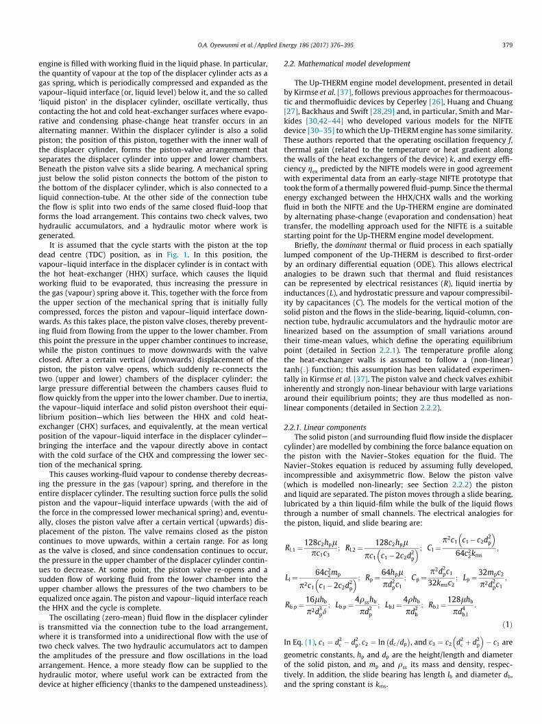
2.2.1. Linear componentsThe solid piston (and surrounding fluid flow inside the displacer
cylinder) are modelled by combining the force balance equation onthe piston with the Navier–Stokes equation for the fluid. TheNavier–Stokes equation is reduced by assuming fully developed,incompressible and axisymmetric flow. Below the piston valve(which is modelled non-linearly; see Section 2.2.2) the pistonand liquid are separated. The piston moves through a slide bearing,lubricated by a thin liquid-film while the bulk of the liquid flowsthrough a number of small channels. The electrical analogies forthe piston, liquid, and slide bearing are:
Rl;1 ¼128c2hplpc1c3
; Rl;2 ¼ 128c2hplpc1 c1�2c2d
2p
� � ; Cl ¼p2c1 c1�c2d
2p
� �64c22kms
;
Ll ¼ 64c22mp
p2c1 c1�2c2d2p
� � ; Rp ¼64hplpd2
pc1; Cp ¼
p2d2pc1
32kmsc2; Lp ¼32mpc2
p2d2pc1
;
Rb;p ¼16lhb
p2d3pd
; Lb;p ¼4qsshb
pd2p
; Lb;l ¼4qhb
pd2b
; Rb;l ¼128lhb
pd4b;l
:
ð1Þ
In Eq. (1), c1 ¼ d2c � d2
p; c2 ¼ ln dc=dp� �
, and c3 ¼ c2 d2c þ d2
p
� �� c1 are
geometric constants, hp and dp are the height/length and diameterof the solid piston, and mp and qss its mass and density, respec-tively. In addition, the slide bearing has length lb and diameter db,and the spring constant is kms.

Fig. 2. Imposed non-linear temperature profile along the heat-exchanger walls,exhibiting a saturation at DThx=2 on either side of the equilibrium (mean)temperature.
380 O.A. Oyewunmi et al. / Applied Energy 186 (2017) 376–395
Liquid columns are modelled by applying the Navier–Stokesequation, simplified with the same assumptions as for the mod-elling of the liquid surrounding the piston. Based on this approach,the resistance, inductance and capacitance of each liquid columnare given by:
R ¼ 128ll0pd4
0
; L ¼ 4ql0pd2
0
; C ¼ pd20
4qg; ð2Þ
where the length of the liquid column is represented by l0, itsdiameter by d0, the viscosity and density of the liquid in the columnby l and q, and g is the gravitational acceleration. It should benoted that the hydrostatic pressure difference only applies for theliquid column in the displacer cylinder, as the other cylindersare completely filled with liquid and thus have constantliquid-column height.
The hydraulic accumulators are modelled as linear gas springs.It is assumed that the gas at the top of the accumulators is com-pressed/expanded isentropically and therefore, based on an ideal-gas approximation, the process observes PVc ¼ const:, and thecapacitance of each accumulator gas spring is:
C ¼ V0
cP0; ð3Þ
where V0 and P0 respectively are the equilibrium volume and pres-sure of the gas in the accumulators.
A torque balance is applied on the motor, which leads to thefrictional losses and inductance of the motor:
Rhm ¼ 16llubd3s ls
p�d4d2m
; Lhm ¼ 8mm
p2d4 ; ð4Þ
where llub is the viscosity of the lubricant around the shaft, ls and ds
the length and diameter of the shaft, � the gap between the motorand the shaft, d the diameters of the inlet and outlet pipes of themotor, and dm andmm the diameter and homogeneously distributedmass of the motor. The useful instantaneous mechanical power thatcan be extracted from the device is dissipated in a further electricalresistance Rgen:
_W ¼ RgenU2hm; ð5Þ
where Uhm is the (volumetric) fluid flow-rate through the hydraulicmotor, and Rgen is determined empirically to maximize the poweroutput from the Up-THERM converter, as described in Section 2.4.2.We do not differentiate in this work between mechanical and elec-trical power output.
Other performance indices useful in characterizing the Up-THERM engine, in particular a few efficiency measures, are definedin Section 2.3. A detailed description of the modelling approach forthe hydraulic motor and the other linear components can be foundin Kirmse et al. [37].
2.2.2. Non-linear componentsIn the thermal domain, the temperature profile along the HHX–
CHX heat-exchanger surfaces that are in contact with the workingfluid is modelled by using a tanhf:g function that saturates whenthe vapour–liquid interface position (y) moves far away from theequilibrium position at y ¼ 0, as shown in Fig. 2 [34]:
Thx ¼ a tanhðbyÞ: ð6ÞIn Eq. (6), a is half of the maximum temperature difference betweenthe HHX and CHX, and the product ab is the gradient of the temper-ature profile at and close to the origin, as defined in Fig. 2.
The (rate of) thermal energy exchanged between the heatexchangers and the working fluid can be described via a convective(phase-change) heat transfer coefficient h,
_Q ¼ hAhxðThx � TwfÞ � T0_S; ð7Þ
with T0 the equilibrium temperature, _S the corresponding entropyflow-rate, Ahx the area over which phase-change heat transferoccurs, and Twf the working-fluid temperature.
The thermal domain must be coupled to the fluid domain, as therest of the engine is described in the fluid domain. Two couplingequations are employed for this purpose [30]:
_S ¼ qgsfgUth; ð8Þ
Thx ¼ dTdP
� �satPth; Twf ¼ dT
dP
� �satPC;v: ð9Þ
In the above equations, qg is the density of the working fluid in thevapour phase, sfg is the phase-change specific entropy, Uth is the vol-umetric flow-rate, ðdT=dPÞsat is the rate of change of temperaturewith pressure in the saturation region of the working fluid, andPth and PC;v are the pressures in the thermal domain and the gas(vapour) spring at the top of the displacer cylinder, respectively.
Thus, the volumetric flow-rate due to heat exchange (leading toevaporation/condensation) becomes:
Uth ¼ Pth � PC;v
Rth; Rth ¼ qgsfgT0
hAhxðdT=dPÞsat; ð10Þ
where Rth is the thermal resistance.The piston valve in the displacer cylinder is modelled by using a
combination of two Heaviside step-functions to account for thetwo instances in the cycle where the valve opens/closes:
Rpv ¼ Rmin þ 12Rmax �HfPC;d � qwflghg þ HfPC;d þ qwflghg
� �: ð11Þ
In Eq. (11), Rmin is a constant minimum resistance due to viscousdrag when the valve is open and Rmax a large pre-set constant resis-tance applicable when the valve is closed. In addition, PC;d is thehydrostatic pressure of the liquid column inside the displacercylinder, qwfl is the density of the working-fluid liquid and h isthe distance of the solid piston from its time-mean equilibriumposition.
The check valves in the load arrangement are also modelledusing a Heaviside step-function. Each check valve remains openedwhen there is a positive fluid flow-rate U through it and closes atthe moment when the flow rate becomes negative:
Rcv ¼ RmaxHfUg: ð12Þ

O.A. Oyewunmi et al. / Applied Energy 186 (2017) 376–395 381
A third non-linear resistance is introduced to ensure that theamplitudes of the piston and liquid flow in the displacer cylinderare not larger than the geometric dimensions (height) of the dis-placer cylinder:
Rnl ¼ Rmax �HfPC;d � qwflgh3g þ HfPC;d þ qwflgh3g� �
; ð13Þwhere h3 is the maximum allowable amplitude by this expression.
Finally, the models of all individual components are then inter-connected in the same way as they are in the physical engine,resulting in the circuit diagram shown in Fig. 3.
2.2.3. Heat transfer coefficientEq. (7) describes the heat input from the heat source to the
working fluid. This process involves evaporative heat transfer toboil the working fluid, and is taken as a pool-boiling process in thiswork. Thus, a key parameter to be evaluated for this process is thepool-boiling heat transfer coefficient, h. The heat transfer coeffi-cient h can be calculated by using the reference heat transfer coef-ficient for a specific fluid h0 and a correlation for the reduced heattransfer coefficient [45]:
hh0
¼ FqFpFw: ð14Þ
For most fluids experimental values of h0 exist, and are avail-able from Table 1 of Section H2 in the VDI Heat Atlas [45]. For flu-ids for which experimental values do no exist, a calculationprocedure is presented in the VDI Heat Atlas. In Eq. (14) the func-tions Fi are dimensionless and independent of the fluid. They takeinto account the heat flux, the reduced pressure ðpr ¼ p=pcÞ of thefluid, and the properties of the heat-exchanger wall. The functionFq is dependent on the heat flux q, the reference heat fluxq0 ¼ 20 kWm�2, and an exponent n that is dependent on thereduced pressure and the fluid properties:
Fq ¼ qq0
� �n
; ð15Þ
where n is given by:
Fig. 3. Circuit diagram of the Up-THERM heat engine; colours correspond to the engine cois the volumetric flow-rate through a component. The subscript ‘th’ denotes the thermal‘l’, the piston ‘p’, the fluid flow in the slide bearing ‘b, l’, the piston in the slide bearing ‘b, pcylinder, and the non-linear valve formed by the piston and cylinder ‘pv’. The load comhydraulic motor ‘hm’. (For interpretation of the references to colour in this figure legen
n ¼ 0:9� 0:3p0:15r ; for water
0:95� 0:3p0:3r ; for organic fluids:
(ð16Þ
The function Fp takes the pressure dependability of the reducedheat-transfer coefficient into account. It is calculated as:
Fp ¼ 1:73p0:27r þ 6:1p2
r þ 0:68p2r =ð1� p2
r Þ; for water0:7p0:2
r þ 4pr þ 1:4pr=ð1� prÞ; for organic fluids:
(
ð17ÞThe function Fw takes the properties of the heat-exchanger
material into account. It can be split into a function Fwr, which con-siders the surface roughness of the heat-exchanger wall, and afunction Fwm that considers the wall material, so thatFw ¼ FwrFwm. Fwr can be calculated by:
Fwr ¼ Ra
Ra0
� �2=15
; ð18Þ
where Ra0 ¼ 0:4 lm is the reference surface roughness for metalsurfaces. Ra is the measured surface roughness. If this value is notknown then Ra ¼ Ra0 ¼ 0:4 lm, so that Fwr ¼ 1 [46]. The functionFwm accounts for the wall material by using the ratio of the effusiv-ity b ¼ ffiffiffiffiffiffiffiffi
kqcp
of the wall material to the effusivity of the referencematerial, copper b0 ¼ 35:35 kW s0:5 m2 K:
Fwm ¼ bb0
� �0:5
: ð19Þ
2.3. Performance indices and efficiency definitions
Four indicators—oscillating frequency (f), power outputðP ¼ _WÞ, exergy efficiency ðgexÞ and thermal efficiency ðgth)—areused to describe the performance of the Up-THERM device. Ofthese, the oscillating frequency is unique to unsteady thermoflu-idic heat engines such as the NIFTE and the Up-THERM. The poweroutput and efficiencies, on the other hand, are commonly encoun-tered performance indicators used in describing heat engines in
mponents in Fig. 1. Ri denotes a resistance, Li an inductance and Ci a capacitance. Ui
domain. The single components of the fluid domain are the leakage flow denoted by’, the connection tube ‘c’, the liquid column ‘d’ and the gas spring ‘v’ in the displacerprises the two check valves ‘cv, i’, two pipes ‘t, i’, hydraulic accumulators ‘a, i’ andd, the reader is referred to the web version of this article.)

Table 1Nominal values for electrical analogy parameters. Superscript * denotes parametersthat are directly dependent on heat-source/sink temperature and working-fluidthermodynamic properties.
Electricalparameter
Thermal-fluid effect Nominalvalue
Units
C�d Displacer cylinder
capacitance1:81� 10�8 m4 s4 kg�1
Cl Leakage flow capacitance 1:78� 10�10 m4 s4 kg�1
Cp Piston capacitance 6:02� 10�10 m4 s4 kg�1
C�v Linear gas spring displacer
cylinder3:38� 10�9 m4 s4 kg�1
L�c Connection tube inductance 2:03� 105 kg m�4
Lhm Hydraulic motor inductance 3:09� 106 kg m�4
L�d Displacer cylinder inductance 8:44� 106 kg m�4
Ll Leakage flow inductance 6:45� 107 kg m�4
L�t;i Fluid flow in load pipes 2:02� 106 kg m�4
Lp Piston inductance 5:96� 106 kg m�4
L�b;l Fluid flow inductance in slidebearing
9:18� 106 kg m�4
Lb;p Piston inductance in slidebearing
3:01� 106 kg m�4
Rc Connection tube resistance 5:81� 102 kg m�4 s�1
Rhm Hydraulic motor resistance 5:67� 107 kg m�4 s�1
Rd Displacer cylinder resistance 8:68� 105 kg m�4 s�1
Rl;1 Leakage flow resistance (1) 6:24� 107 kg m�4 s�1
Rl;2 Leakage flow resistance (2) 1:28� 106 kg m�4 s�1
Rt;i Fluid flow in load pipes 7:44� 104 kg m�4s�1
Rp Piston resistance 9:86� 104 kg m�4 s�1
Rb;l Fluid flow resistance in slidebearing
5:31� 107 kg m�4 s�1
Rb;p Piston resistance in slidebearing
7:74� 105 kg m�4 s�1
R�th Thermal resistance 6:36� 107 kg m�4 s�1
382 O.A. Oyewunmi et al. / Applied Energy 186 (2017) 376–395
general. The frequency of operation of the Up-THERM is deter-mined by examining the cyclic steady-state time profiles of thepressure oscillation in the displacer cylinder. The period of oscilla-tion is determined as the time between three successive pointswith zero amplitude (i.e., the time for one full cycle). The frequencyis thus calculated as the inverse of this period.
The instantaneous power output from the Up-THERM heatengine has been introduced in Eq. (5) (Section 2.2.1) as the productof the generator resistance ðRgenÞ and the square of the instanta-neous volumetric flow-rate through the hydraulic motor ðUhmÞ.The power generated over a cycle is calculated as:
_W ¼I
RgenUhmdV load ¼I
PloaddV load; ð20Þ
where V load ¼ HUhmdt is the volume in the load and Pload ¼ RgenUhm
is the pressure in the load.The exergy efficiency is calculated as the ratio of the power gen-
erated to the exergy input to the cycle:
gex ¼HPloaddV loadHPthdV th
: ð21Þ
Here, Pth is the thermal pressure (referred heat-exchanger temper-ature) and V th is its thermal volume (referred entropy flow due toheat transfer), with V th ¼ H ðU þ UvÞdt.
A measure of the thermal efficiency follows as a product of theexergy efficiency and Carnot efficiency:
gth ¼ gex � 1� Tcold
Thot
� �: ð22Þ
where Tcold is the minimum temperature of the heat sink, and Thot isthe maximum temperature of the heat source. These temperatures(Tcold and Thot) correspond respectively to the supply temperaturesof the cooling stream (heat sink) and the heating stream (heatsource) to the engine. It should be noted that this thermal efficiencyis slightly overestimated as both the heat-source and heat-sinktemperatures do not remain constant in the heat exchangers.
2.4. Nominal Up-THERM engine configuration
The Up-THERM engine was conceived primarily for solar powerand waste heat recovery applications. The first prototype of thisengine was proposed by the company Encontech [38], and thiswas followed by an Up-THERM prime-mover designed to convertheat to power as part of a gas-fired micro-CHP unit in the EU-funded project ‘Up-THERM’. The initial working fluid consideredfor these engines was water.
In the CHP prototype, thermal energy is transferred from thehot combustion gases in the gas boiler to the HHX of the Up-THERM with a flow of diathermal oil Therminol 68� at a flow rateof 0.6 kg s�1. The oil stream (heat source) temperature ðThsÞ israised to 360 �C, while the heat-sink (cooling-water stream) tem-perature ðTsinkÞ is around 10 �C. The working-fluid equilibriumtemperature lies approximately midway between the heat-sourceand sink temperatures:
Tsat ¼ Teq ¼ Ths þ Tsink
2; ð23Þ
and the equilibrium pressure is the saturation pressure at thistemperature.
The working fluid extracts thermal energy from the heat sourcefor subsequent conversion to mechanical work. The amount of heatdelivered to the working fluid is governed by Eqs. (6)–(10), whichare all influenced by the thermodynamic properties of the workingfluid, the heat-source temperature and the heat-exchanger design.Thus it is to be expected that different working fluids will extract
different amounts of heat from the heat source. For example, atthe given pre-specified (fixed) nominal design conditions (see Sec-tion 4.2), water extracts 42.7 kW from the heat source whiletoluene extracts 9.4 kW; R113 extracts the highest amount of heatfrom the heat source (180 kW) and subsequently delivers the high-est power output. The performance of the engine at varying sourcetemperatures is investigated in Section 4.3.
2.4.1. Engine nominal parameters and nominal performanceThe physical dimensions of the Up-THERM engine were consid-
ered in Kirmse et al. [37], with water as the working fluid. Here, inTable 1, we list the resulting nominal electrical parameters (resis-tances, capacitances and inductances) from that work. Theseparameters directly correspond to those in Fig. 3 and most of themremain unchanged in the present work. Those that depend on theheat-source temperature and the thermodynamic properties of theworking fluid (highlighted by ‘‘*” in Table 1), change accordingly. Anumerical simulation of the model (using ODE solvers in MATLAB[34,47,48]) with the nominal parameters in Table 1 results in thenominal performance of the engine presented in Table 2.
The time-varying volumetric flow-rates in key engine sectionsduring nominal operation are shown in Fig. 4a. It can be observedthat a limit cycle is attained from about 2.5 s; after initial tran-sients in pressures and flow rates, the oscillations are sustainedat a constant frequency and amplitude. In this figure, U is the vol-umetric (liquid) flow-rate through the displacer cylinder and intothe connection tube (which is also equal to the flow rate fromthe connection tube to the load arrangement) and Upist representsthe movement of the piston in the displacer cylinder. Both of theseflow rates are seen to oscillate about a mean value of zero, withUpist having larger amplitudes than U due to leakage around thepiston and through the slide bearings. Furthermore, Uphm1 is thevolumetric (liquid) flow-rate through the check valve that ‘feeds’

Table 2Model results for nominal operation of Up-THERM heat engine.
Power output 2.64 kWExergy efficiency 11.2%Thermal efficiency 6.18%Frequency 1.67 Hz
(a)
(b)
Fig. 4. Variations in volumetric flow-rate (U) and pressure (P) in key enginesections. (a) Volumetric flow-rates through the connection tube (U), the forwardcheck-valve ðUphm1Þ, the hydraulic motor ðUhmÞ and the piston ðUpistÞ. (b) Pressurevariations in the displacer cylinder ðPC;l;dcÞ, of the piston ðPC;pistÞ and in one of thehydraulic accumulators ðPC;acc1Þ.
O.A. Oyewunmi et al. / Applied Energy 186 (2017) 376–395 383
the hydraulic motor. This flow is always positive with the samepeak amplitude as U due to the non-return action of the valve thatprevents Uphm1 from having a significant negative amplitude sinceonly a small amount of liquid can flow back before the valve closes.When the valve is fully open, the flow rates Uphm1 and U are iden-tical. This means that all the liquid from the displacer cylinder andvia the connection tube flows through the check valve into theaccumulator and the hydraulic motor. Downstream of the accumu-lator the volumetric (liquid) flow-rate Uhm is equal to the flow ratethrough the hydraulic motor, and this is always positive due to theaction of the check valves providing uni-directional flow. It does,however, experience reduced amplitudes of oscillation due to thedampening action of the two hydraulic accumulators.
Time-varying pressures in important engine sections are shownin Fig. 4b. In particular, PC;l;dc is the hydrostatic pressure of the liq-uid column in the displacer cylinder below the piston, and is thus ameasure of the height of the liquid column below the piston. Theamplitude of PC;l;dc is smaller than that of the piston pressure
PC;pist and that of the pressure in the hydraulic accumulatorPC;acc1. PC;pist is the pressure exerted by the compressed mechanicalsprings and therefore it represents the piston position in the dis-placer cylinder. The highest pressure amplitude can be observedin the piston as it is directly connected to the displacer cylinderwhere the phase change and resultant pressure forcing arises.
2.4.2. Optimal load characterizationWhile the nominal electrical analogy parameters (RLCs) of the
Up-THERM engine have been defined, the load resistance Rgen isyet to be determined as it is external to the engine. This is the resis-tance presented by the employed generator, and the powerextracted from the engine is strongly correlated with this parame-ter. It would be expected that there is a value of Rgen that optimizessome performance criterion of the engine. Thus, the optimal Rgen
needs to be defined relative to the performance criterion, e.g., max-imum power output or maximum efficiency; here we use the max-imum power output. This is especially important in waste-heatrecovery applications, where the aim is to maximize power outputper unit cost [7].
The power output from the engine is defined in Eqs. (5) and(20). From these relations, one would expect higher power outputsat higher values of Rgen, as the power output appears to be directlyproportional to Rgen. However, this increase is not sustained due tothe dependence of the power output on the flow rate through thehydraulic motor ðUhmÞ. At higher values of Rgen, when there is ahigher resistance to the flow through the motor, Uhm decreasessince Uhm ¼ Pload=Rgen, and since the power output also appearsto have a direct proportionality to the square of Uhm, it decreases.Thus, the power output varies non-monotonically with Rgen, andthe optimal Rgen that maximizes the power output is a compromisebetween these two factors.
In order to determine the optimal generator resistance, we per-form simulations at different cycle heat-source temperatures andwith a selection of working fluids (n-pentane, water, ammoniaand R245fa), over a range of Rgen values. In Fig. 5a and b the oscil-lating frequency and power output, respectively, are plotted asfunctions of Rgen for four working fluids at a heat-source tempera-ture of 200 �C. In addition, power outputs when using differentheat-source temperatures are plotted in Fig. 5c. For some workingfluids and at lower heat-source temperatures (e.g., water at 200 �Cand pentane at 100 �C), there are no sustained oscillations in theengine due to the very low flow rates caused by the high generatorresistances ðRgen > 5� 108 kg m�4 s�1Þ.
From the figures, it can be seen that the oscillatingfrequency remains largely invariant to the generator resistance,whereas the power output is strongly affected by the value ofRgen. As expected, the power output is almost negligible at low
values of Rgenð< 106 kg m�4 s�1Þ and also at high values of
Rgenð> 1010 kg m�4 s�1Þ. The power output peaks in the range
2� 107 kg m�4 s�1 to 7� 107 kg m�4 s�1, irrespective of theworking fluid employed or the heat-source temperature. For mostof the simulations, the maximum power is generated at a value ofRgen ¼ 5:6� 107 kg m�4 s�1, and thus this value of Rgen is employedas the optimal value for the subsequent simulations in this work.For a few of the working fluids, e.g., some siloxanes, the optimalRgen differs from the above value, but only slightly, usually in therange of �5%. The optimal value of Rgen is therefore generallyinsensitive to the choice of the working fluid but mainly a functionof the engine configuration and component sizes. Thus, it should benoted that the selection of the optimal Rgen is key in designing anoptimal engine configuration and, as such, the designer shouldensure the right value is selected for the engine configurationand imposed external conditions.

(a) (b) (c)
Fig. 5. Up-THERM engine performance as a function of generator resistance ðRgenÞ. (a) Engine oscillating frequency (f) with four working fluids and heat-source temperatureof 200 �C. (b) Engine power output ðP ¼ _WÞ with four working fluids and heat-source temperature of 200 �C. (c) Engine power output ðP ¼ _WÞ with four working fluids andvarious heat-source temperatures.
Fig. 6. Variations in normalized working-fluid thermodynamic properties ðXnÞ—entropy change during vaporization ðsfgÞ, enthalpy change during vaporization ðhfgÞ,volume change during vaporization ðv fgÞ, liquid-phase density ðqlÞ, vapour-phasedensity ðqgÞ, saturation pressure (Psat) and vapour-phase heat-capacity ratio (cg)—with saturation temperature (Tsat) for water as the working fluid. Each thermody-namic property is normalized between 0 and 1 using the formulaXn ¼ ½X � Xmin =½Xmax � Xmin , where X represents any of the aforementioned ther-modynamic properties.
384 O.A. Oyewunmi et al. / Applied Energy 186 (2017) 376–395
3. Thermodynamic property characterization of the Up-THERMengine
Having characterized the optimal configuration of the Up-THERM heat engine with respect to the imposed external condi-tions, it is of interest to investigate the performance of the enginewith various working fluids, and to attempt to characterize theengine’s performance in relation to the thermodynamic propertiesof suitable working fluids. This can enable a determination of theproperties that have the most significant effects on the engine per-formance and aid in the screening of working fluids in future selec-tion processes, similarly to what was attempted for another TFOdevice (the NIFTE) by Markides et al. [35].
In order to determine the most-important thermodynamicproperties, we carry out a parametric investigation on the engine’sexergy efficiency and power output where each thermodynamicproperty (or property combination) is varied separately and inde-pendently while the others are set to their nominal values at thenominal saturation temperature. The independent properties inves-tigated are the: saturation temperature ðTsatÞ; entropy change dur-ing vaporization ðsfgÞ; vapour-phase heat-capacity ratio ðcgÞ;vapour-phase density ðqgÞ; liquid-phase density ðqlÞ; and satura-tion pressure ðPsatÞ. The enthalpy change during vaporizationðhfgÞ and volume change during vaporization ðv fgÞ, although depen-dent on Tsat & sfg and qg & ql respectively, are also investigated inthe first instance.
Water is used as the reference working fluid here, due to its lar-ger thermodynamic property variations, e.g., in hfg and sfg, overorganic fluids. The nominal point is set at an equilibrium/saturationtemperature of 185 �C, which corresponds to heat-source and heat-sink temperatures (from Eq. (23)) of 360 �C and 10 �C respectively.The nominal values of the investigated thermodynamic propertiesare thus calculated at 185 �C. Tsat is varied from 20 �C through thenominal point to the critical temperature. The values of sfg;hfg andv fg generally decrease with increasing Tsat, becoming zero at thecritical temperature. The liquid-phase density ql also decreaseswith increasing Tsat, but at the critical temperature it becomes equalto qg, which increases with Tsat. Both Psat and cg also increase withincreasing Tsat, with cg increasing very rapidly closer to the criticaltemperature. These trends are illustrated in Fig. 6.
3.1. Individual thermodynamic property variations
The results of varying each of the aforementioned thermody-namic properties independently are presented in Fig. 7. The oscil-lating frequency f is generally insensitive to these variations
(Fig. 7a), although deviations from the nominal frequency can beseen with changes to the volume change during vaporization v fg
and saturation pressure Psat. The increase in f at higher (and slightdecrease at lower) Psat is to be expected as larger pressures corre-spond to larger driving forces, generating more-frequent oscilla-tions (and vice versa).
The influence of the thermodynamic properties on the exergyefficiency gex and the power output P ¼ _W are presented inFig. 7b and 7c. Amongst the independent properties, Psat and qg
have the greatest combined effect on the exergy efficiency andpower output from the Up-THERM engine. The volume andentropy changes during vaporization, v fg and sfg, and the saturationtemperature Tsat also have some effect on these indices, while cg;ql
(the only liquid-phase property) and hfg are less-important proper-ties in affecting performance in this analysis. The fact that Tsat hasonly a slight effect on the engine performance (the power outputdecreases slightly as Tsat is increased) may suggest that it is not akey thermodynamic property with respect to power output andexergy efficiency. It does however play a key role in the initialscreening and selection of working fluids as detailed in Section 4.1.
In particular, v fg (a function of qg and ql), is seen to have a pro-found effect on the exergy efficiency, especially at low saturationtemperatures (corresponding to higher values of v fg; see Fig. 6).

Fig. 7. Performance indices of the Up-THERM heat engine with water as theworking fluid on independently varying its thermodynamic properties—entropychange during vaporization (sfg), volume change during vaporization (v fg), satura-tion temperature (Tsat), vapour-phase heat-capacity ratio (cg), vapour-phase density(qg), liquid-phase density (ql), saturation pressure (Psat) and enthalpy changeduring vaporization (hfg). Each property is varied between the indicated saturationtemperature (Tsat) range while others are set to their respective nominal values at asaturation temperature of 185 �C.
O.A. Oyewunmi et al. / Applied Energy 186 (2017) 376–395 385
Also, high values of v fg (at low Tsat) lead to very low power outputsfrom the engine, in contrast to the fact that higher oscillating fre-quencies are experienced at these high values. When v fg is large,there is a larger volume of working-fluid vapour generated duringevaporation over the hot heat-exchanger per unit heat (and exergy)input, which translates to increased positive-displacement workper unit heat input, i.e., higher efficiency such as seen in Fig. 7b.At the same time, the heat/exergy input to the engine is verylow, which eventually translates to reduced power outputs.
From Fig. 7c, the engine is seen to produce higher power outputsat low values of qg (at low Tsat) and to produce lower power outputsat higher values. This can be attributed to the influence of theseproperties on the thermal resistance Rth. Referring to Eq. (10), Psat
varies directly with qg and Tsat; thus low values of qg and Tsat leadto low thermal resistances, which enable more heat to beexchanged between theworking fluid and the heat exchangers. Thiseventually makes more thermal energy available for subsequentconversion to power in the load arrangement. Similarly at low val-ues of sfg (corresponding to high Tsat), a lower thermal resistance isexperienced leading to higher power outputs from the engine.
The saturation pressure Psat has the greatest influence of all var-ied properties on the power output in Fig. 7c. The power outputincreases with Psat from low values to values above the nominal,beyond which a maximum is observed at a pressure of 69.6 bar(corresponding to a reduced pressure and temperature of 0.315and 0.863 respectively). While qg is equally important, it has anopposite effect to that of Psat. Higher values of Psat lead to higherpower outputs, while lower values of qg also lead to higher poweroutputs. For any single working fluid, it is almost impossible tosimultaneously achieve a high value of Psat and a low value of qg
since both properties increase (or decrease) with increasing (ordecreasing) Tsat. Therefore, in most cases a compromise has to bereached between these properties; this relationship is furtherexplored in the next subsection by simultaneously varying groupsof thermodynamic properties.
3.2. Combined thermodynamic property variations
In the previous section, the saturation pressure Psat and thevapour-phase density qg were identified as very significant proper-ties in describing the Up-THERM engine performance. We nowvary combinations of (two, three and four) properties to investi-gate any synergies that may exist between property groups andto also identify which of Psat or qg is more important in affectingperformance. The resulting performance predictions are presentedin Fig. 8 for the exergy efficiency and Fig. 9 for the power output.Some combined variations (e.g., of sfg and cg) result in higher effi-ciencies and/or power outputs over the individual properties.
From the results, the key role of varying Psat in affecting perfor-mance persists when it is varied in combination with other proper-ties. In particular, the simultaneous variation of Psat and sfg has astronger effect on both the power output and exergy efficiencythan varying Psat alone. Efficiency and power output (up to a point)are both seen to increase with the combination of high Psat and lowsfg. Interestingly, however, the combination of high Psat and Tsat
causes a reduction in power output from that previously attainedat higher Psat alone. Thus a combination of high saturation pres-sures and low equilibrium/saturation temperatures is needed tomaximize power output from the engine. This suggests that oneneeds a fluid with as high a Psat as possible at any correspondingTsat to maximize the power output.
Similarly, the performance trends in the variations of qg areseen to persist when other thermodynamic properties are
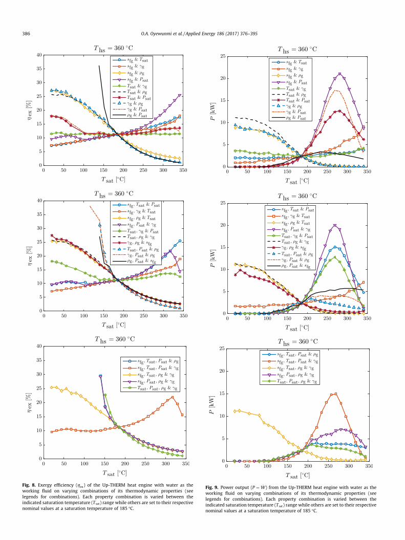
Fig. 8. Exergy efficiency (gex) of the Up-THERM heat engine with water as theworking fluid on varying combinations of its thermodynamic properties (seelegends for combinations). Each property combination is varied between theindicated saturation temperature (Tsat) range while others are set to their respectivenominal values at a saturation temperature of 185 �C.
Fig. 9. Power output (P ¼ _W) from the Up-THERM heat engine with water as theworking fluid on varying combinations of its thermodynamic properties (seelegends for combinations). Each property combination is varied between theindicated saturation temperature (Tsat) range while others are set to their respectivenominal values at a saturation temperature of 185 �C.
386 O.A. Oyewunmi et al. / Applied Energy 186 (2017) 376–395
O.A. Oyewunmi et al. / Applied Energy 186 (2017) 376–395 387
simultaneously varied. As expected, the improvements on perfor-mance due to simultaneous variations of Tsat and qg or cg and qg
are insignificant compared to those of varying qg alone. There is,however, a slight increase in power output at combinations oflow qg and low Tsat.
The simultaneous variation of combinations of Psat and qg isseen to result in very different trends from those obtained whenthese properties are varied individually. In fact, variation in eachproperty tends to nullify the effect of the other on the power out-put; they do, however, reinforce each other in terms of the exergyefficiency, with gex increasing rapidly from the nominal value atlower values of qg and Psat. Thus, for a high-power design oneneeds a combination of a high Psat and high qg fluid (low qg shouldbe avoided), whereas for a high-efficiency design a combination oflow qg and low Psat is needed. In order to simultaneously attain ahigh power output and a high exergy efficiency one needs a com-bination of high Psat and low qg, which is not physically realizablefor most known fluids as both Psat and qg increase with Tsat. Thissuggests that power output and efficiency are competing perfor-mance objectives; high-power designs will generally have lowerexergy efficiencies and vice versa.
The simultaneous variation of combinations of three or fourproperties serve to further confirm the earlier findings, since thegeneral trends (in variations of Psat and qg) from both the single-property and two-property variations are found to persist whenthree or more properties are varied simultaneously. When eitherTsat; cg or sfg are varied in combination with Psat and qg the previoustrends in power and efficiency persist, especially the sharp increasein efficiency below the nominal point. This supports the earlierinference of the competition between power output and exergyefficiency, and further highlights the conflicting importance of qg
and Psat. The identification of these key combinations of thermody-namic properties is particularly important and informative for thecomputer-aided molecular design (CAMD) of these engines.
3.3. Comparison with an ideal two-phase and other thermofluidicdevices
As earlier stated, the Up-THERM engine and the Non-Inertive-Feedback Thermofluidic Engine (NIFTE), both belong to the sameclass of two-phase oscillatory heat engines known as thermofluidicoscillators. These two-phase engines in general can be charac-terised by a working fluid thermal efficiency, gwf . This is a theoreticalideal thermal efficiency relating to the useful work done in trans-ferring a working fluid across two constant-pressure (and temper-ature) reservoirs, employing only positive-displacement phase-change processes and ignoring any exergy destruction via valvesand thermal losses [35]. This generally characterises any two-phase heat engine as no information about the physical engine(Up-THERM or NIFTE or otherwise) is required in its definition. Aworking fluid exergy efficiency gwf;ex can be further defined by divid-ing gwf by the Carnot efficiency corresponding to the hot and coldtemperature reservoirs.
An investigation of the effect of working fluids and their ther-modynamic properties on gwf was carried out by Markides et al.[35], to highlight the working fluids with the highest potential toconvert heat to work in any two-phase heat engine. They foundthat gwf generally increases with the heat-addition temperatureirrespective of the working-fluid employed, as expected. However,its exergetic component, gwf;ex, decreases with heat-addition tem-perature. Also, the organic working fluids (pentane and R245ca)were seen to exhibit higher gwf;ex and lower gwf in comparison tothe hydrogen-bonding fluids (water and ammonia) at the samereduced temperatures. Furthermore, amongst the working-fluid
thermodynamic properties, the volume change during vaporiza-tion ðv fgÞ had the strongest effect on gwf , with gwf decreasing withdecreasing v fg (increasing Tsat). The saturation pressure ðPsatÞ leadsto the second-largest deviation, with gwf increasing with Psat. Otherthermodynamic properties had less significant effects on the work-ing fluid efficiencies.
These results are replicated in both the NIFTE and the Up-THERM where changes in v fg have the greatest influence on theexergetic efficiencies of both devices. In the Up-THERM, the exergyefficiency decreases with decreasing v fg. In the NIFTE however, theexergy efficiency increases with decreasing v fg in the first instance,until a maximum and then decreases [35]. Psat and the entropychange during vaporization ðsfgÞ are also seen to have significanteffects on the exergy efficiency of the Up-THERM and its poweroutput. In addition, thermodynamic properties such as theliquid-phase density ðqlÞ, the vapour-phase heat-capacity ratioðcgÞ and the saturation temperature ðTsatÞ are seen to have less sig-nificant effects on the exergy efficiencies of both the NIFTE and theUp-THERM engines. Finally, while the effect of the vapour-phasedensity ðqgÞ on the working fluid efficiency and the exergy effi-ciency of the NIFTE was not reported, it is seen to have significanteffects on the efficiencies and power output of the Up-THERM.
4. Working-fluid selection for the Up-THERM engine
4.1. Available working fluids
Currently, there are a number of publications on working-fluidselection for different heat engines, especially for the ORC variants.It is generally accepted that it is challenging to select an optimalworking fluid for all cycle configurations, operating conditionsand heat-source temperatures, which makes it difficult to general-ize working-fluid selection rules across different cycles. Chen et al.[49], in an investigation of 35 pure working fluids (refrigerants,hydrocarbons and ammonia) in ORCs, suggested that the criticaltemperature and the slope of the saturated vapour curve (on aT–s diagram) of working fluids are important characteristics toconsider when designing cycles and selecting operating conditions.Furthermore, siloxanes (MM, MDM, MD2M, MD3M and MD4M)have been investigated as suitable working fluids for medium-and high-temperature cycles [10,50].
Various other factors influence the selection of (organic) work-ing fluids, including the stability, material compatibility, safety,environmental impact and purchase cost of the prospective fluids.Organic working fluids are known to suffer chemical and physicaldeterioration at high temperatures, thus the stability of the fluid atthe maximum temperature in the cycle should be consideredbefore selection. The selected working fluid should also be non-corrosive and compatible with the engine materials and lubricants.Various authors [51–55] have presented techniques for studyingthe thermal and chemical stability of various refrigerant-fluid sys-tems. It is also important to ensure that the selected fluid has anegligible environmental imprint in terms of its ozone-depletionpotential (ODP), atmospheric lifetime and global-warming poten-tial (GWP). Refrigerants such as R-11, R-12, R-113, R-114, andR-115 have been phased out while others such as R-21, R-22,R-123, R-124, R-141b and R-142b are in the process of being phasedout due to their detrimental environmental impact [49]. A few ofthese fluids are considered in this work for comparison purposes.
The working fluids considered in this work are listed in Table 3,and include hydrocarbons (straight-chain alkanes, branched alka-nes and aromatics), water and ammonia, refrigerants (halogenatedalkanes) and siloxanes. The properties of these fluids are takenfrom the NIST database [56], which contains experimentally vali-dated data of various fluids. Other approaches for providing

Table 3List of investigated working fluids; phased-out and soon to be phased-out refrigerantsare italicized.
Dry fluids n-Butane, i-butane, pentane, n-hexane, i-hexane, heptane,octane, nonane, decane, R-113, R-114, R-115, R-123, R-141b, R-218, R-236fa, RC-318, D4, D5, D6, MM, MDM, MD2M, MD3M,MD4M
Isentropicfluids
Propane, benzene, toluene, R-11, R-124, R-134a R-142b, R-227ea, R-236ea, R-245ca, R-245fa
Wet fluids Water, ammonia, propylene (propene), R-12, R-22, R-32, R-41,R-125, R-143a, R-152a
388 O.A. Oyewunmi et al. / Applied Energy 186 (2017) 376–395
working-fluid thermodynamic property values do exist, notablyfrom a molecular perspective including the statistical associatingfluid theory (SAFT) equations of state (EoS) [7,9,12,57–61]. Whilethese EoS have been demonstrated to predict accurately the ther-modynamic properties of relevant fluid systems, current databasesare not yet exhaustive, and since the NIST database contains a lar-ger set of fluids, it is preferred for the purposes of the presentstudy. The molecular-based EoS will however play an importantrole in the computer-aided molecular design (CAMD) of workingfluids for waste-heat recovery systems in general [62] and theUp-THERM heat engine in particular.
For a two-phase thermofluidic-oscillator engine like the Up-THERM, it is important that the working fluid is able to undergophase change at the externally imposed cycle temperatures. Thismakes the critical temperature of the working fluid a very impor-tant thermodynamic selection criterion. Specifically, the equilib-rium temperature of the engine (which corresponds to the time-mean saturation temperature of the working fluid) should bebelow the critical temperature of the working fluid ðTeq 6 0:95TcÞto ensure the formation of a vapour phase and present a significantvolume change for sustained physical oscillations. A 95% cut-off isemployed to ensure that the saturation temperature is well belowthe critical temperature. Thus, working fluids with 0:95Tc < Teq aredeemed infeasible in the present work.
The considered fluids are also presented in Fig. 10, where theyhave been plotted based on their critical pressure (on the verticalaxis) and critical temperature (on the lower horizontal axis). Also,the corresponding heat-source temperature (on the upper horizon-tal axis), Ths ¼ 2Teq � Tsink with Tsink set to 10 �C, is displayed suchthat fluids suitable for feasible operation with the Up-THERM can
Fig. 10. Critical pressure (Pc) and temperature (Tc) of investigated working fluidsoverlaid with heat-source temperatures. The vertical dashed line ‘–’ demarcatesfeasible (RHS) from infeasible (LHS) working fluids at a heat-source temperature of360 �C and heat-sink temperature of 10 �C. The alkane formulae, where given andwhere not indicated otherwise, refer to the normal (straight-chain) alkane.
be easily identified and those that are not feasible can be easilyremoved from consideration. The two temperature axes have beenevaluated such that working fluids that fall to the left of a particu-lar heat-source temperature are infeasible; for these fluids theheat-source and also the equilibrium temperatures exceed theimposed critical limit on the saturation temperature. For example,with reference to Fig. 10, at a heat-source temperature of 360 �C(633.15 K), the equilibrium temperature is 185 �C (458.15 K). Thefluids R-113, i-C6H14 and others to the right of the dotted line areapplicable whereas R-141b, R-11 and those falling on the left ofthe line are not applicable since the oscillations in the enginewould lead to near-critical or supercritical operation.
4.2. Working fluids for nominal design
As stated earlier, the Up-THERM engine was nominallydesigned for a heat-source temperature of 360 �C and for cost,safety, availability and environmental-impact reasons, with wateras the working fluid. With a selected heat-sink temperature of10 �C, this gives an equilibrium (and working-fluid time-mean sat-uration) temperature of 185 �C, from Eq. (23). For water, thisresults in a saturation pressure of 11.2 bar. In this section, we con-sider alternative working fluids from Table 3 for the Up-THERMengine at the nominal heat source/sink temperatures. Not all theworking fluids in Table 3 are feasible for the nominal settings ofthe engine. Fluids with a critical temperature Tc below 209 �CðTsat=0:95Þ will operate near or over the critical region of the phasediagram and will be unable to generate two-phase flow and arethus not considered as feasible. These fluids are pre-screened andexcluded from the simulations by utilizing Fig. 10, which has theheat-source temperatures and the corresponding cut-off criticaltemperatures superimposed.
From the pre-screening exercise, only the working fluids to theright of Ths ¼ 360 C, as indicated by the dotted line in Fig. 10, areconsidered feasible for operation with the Up-THERMwhen a heat-source temperature of 360 �C is used. The applicable fluids whichare thus shortlisted for the subsequent simulations are: R113, hex-ane and other higher-molecular-weight alkanes, benzene andtoluene, water, and the siloxanes, for a total of 18 working fluids.It can be seen that heavier alkanes with increasing chain lengthshave progressively higher critical temperatures, and that the silox-anes generally have high critical temperatures.
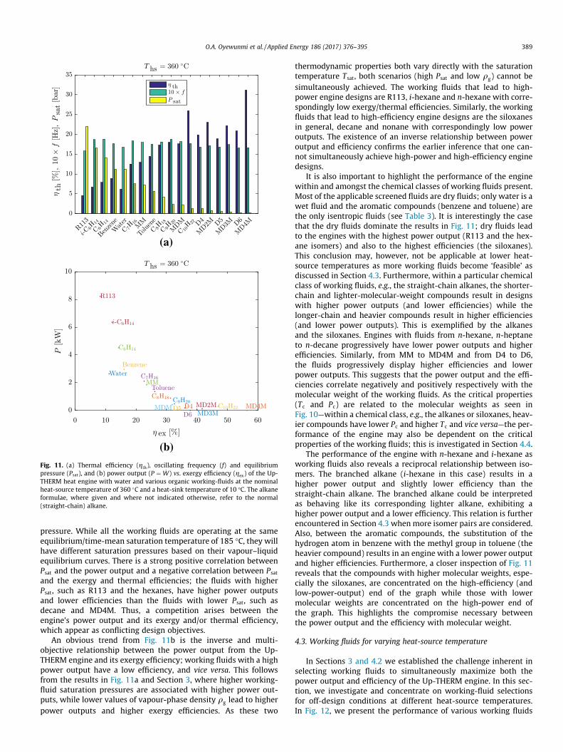
Using the properties of these fluids, the Up-THERM enginemodel is simulated with the nominal heat source/sink conditionsand all other system parameters (e.g., related to the geometry/sizeof the device) kept constant. The results of these simulations arepresented in Fig. 11; in Fig. 11a the resulting thermal efficiency,oscillating frequency and the operating pressure (saturation pres-sure) of the engine with the different working fluids arranged indecreasing magnitude of power output are shown, while a plot ofthe power output against the exergy efficiency of the engine fora given working fluid is shown in Fig. 11b.
When using the different pre-selected working fluids, the oper-ating/oscillating frequency of the Up-THERM engine generally var-ies between 1.5 Hz and 2 Hz with the refrigerant R113 having thelowest frequency and nonane the highest one. Also, the higher-molecular-weight fluids, such as the siloxanes, are seen to exhibitlower frequencies than the lighter working fluids, such as the alka-nes. Overall, the oscillating frequency is not strongly affected bythe choice of working fluid. Also, it is noted that in this analysisthe exergy efficiency and the thermal efficiency are, in fact, propor-tional and will show identical trends, since the heat source andsink temperatures (and therefore, the Carnot efficiency in Eq.(22)) are the same.
One of the more apparent inferences from Fig. 11a is the linkbetween the power output (and/or efficiency) and the saturation
(a)
(b)
Fig. 11. (a) Thermal efficiency (gth), oscillating frequency (f) and equilibriumpressure (Psat), and (b) power output (P ¼ _W) vs. exergy efficiency (gex) of the Up-THERM heat engine with water and various organic working-fluids at the nominalheat-source temperature of 360 C and a heat-sink temperature of 10 �C. The alkaneformulae, where given and where not indicated otherwise, refer to the normal(straight-chain) alkane.
O.A. Oyewunmi et al. / Applied Energy 186 (2017) 376–395 389
pressure. While all the working fluids are operating at the sameequilibrium/time-mean saturation temperature of 185 �C, they willhave different saturation pressures based on their vapour–liquidequilibrium curves. There is a strong positive correlation betweenPsat and the power output and a negative correlation between Psat
and the exergy and thermal efficiencies; the fluids with higherPsat, such as R113 and the hexanes, have higher power outputsand lower efficiencies than the fluids with lower Psat, such asdecane and MD4M. Thus, a competition arises between theengine’s power output and its exergy and/or thermal efficiency,which appear as conflicting design objectives.
An obvious trend from Fig. 11b is the inverse and multi-objective relationship between the power output from the Up-THERM engine and its exergy efficiency; working fluids with a highpower output have a low efficiency, and vice versa. This followsfrom the results in Fig. 11a and Section 3, where higher working-fluid saturation pressures are associated with higher power out-puts, while lower values of vapour-phase density qg lead to higherpower outputs and higher exergy efficiencies. As these two
thermodynamic properties both vary directly with the saturationtemperature Tsat, both scenarios (high Psat and low qg) cannot besimultaneously achieved. The working fluids that lead to high-power engine designs are R113, i-hexane and n-hexane with corre-spondingly low exergy/thermal efficiencies. Similarly, the workingfluids that lead to high-efficiency engine designs are the siloxanesin general, decane and nonane with correspondingly low poweroutputs. The existence of an inverse relationship between poweroutput and efficiency confirms the earlier inference that one can-not simultaneously achieve high-power and high-efficiency enginedesigns.
It is also important to highlight the performance of the enginewithin and amongst the chemical classes of working fluids present.Most of the applicable screened fluids are dry fluids; only water is awet fluid and the aromatic compounds (benzene and toluene) arethe only isentropic fluids (see Table 3). It is interestingly the casethat the dry fluids dominate the results in Fig. 11; dry fluids leadto the engines with the highest power output (R113 and the hex-ane isomers) and also to the highest efficiencies (the siloxanes).This conclusion may, however, not be applicable at lower heat-source temperatures as more working fluids become ‘feasible’ asdiscussed in Section 4.3. Furthermore, within a particular chemicalclass of working fluids, e.g., the straight-chain alkanes, the shorter-chain and lighter-molecular-weight compounds result in designswith higher power outputs (and lower efficiencies) while thelonger-chain and heavier compounds result in higher efficiencies(and lower power outputs). This is exemplified by the alkanesand the siloxanes. Engines with fluids from n-hexane, n-heptaneto n-decane progressively have lower power outputs and higherefficiencies. Similarly, from MM to MD4M and from D4 to D6,the fluids progressively display higher efficiencies and lowerpower outputs. This suggests that the power output and the effi-ciencies correlate negatively and positively respectively with themolecular weight of the working fluids. As the critical properties(Tc and Pc) are related to the molecular weights as seen inFig. 10—within a chemical class, e.g., the alkanes or siloxanes, heav-ier compounds have lower Pc and higher Tc and vice versa—the per-formance of the engine may also be dependent on the criticalproperties of the working fluids; this is investigated in Section 4.4.
The performance of the engine with n-hexane and i-hexane asworking fluids also reveals a reciprocal relationship between iso-mers. The branched alkane (i-hexane in this case) results in ahigher power output and slightly lower efficiency than thestraight-chain alkane. The branched alkane could be interpretedas behaving like its corresponding lighter alkane, exhibiting ahigher power output and a lower efficiency. This relation is furtherencountered in Section 4.3 when more isomer pairs are considered.Also, between the aromatic compounds, the substitution of thehydrogen atom in benzene with the methyl group in toluene (theheavier compound) results in an engine with a lower power outputand higher efficiencies. Furthermore, a closer inspection of Fig. 11reveals that the compounds with higher molecular weights, espe-cially the siloxanes, are concentrated on the high-efficiency (andlow-power-output) end of the graph while those with lowermolecular weights are concentrated on the high-power end ofthe graph. This highlights the compromise necessary betweenthe power output and the efficiency with molecular weight.
4.3. Working fluids for varying heat-source temperature
In Sections 3 and 4.2 we established the challenge inherent inselecting working fluids to simultaneously maximize both thepower output and efficiency of the Up-THERM engine. In this sec-tion, we investigate and concentrate on working-fluid selectionsfor off-design conditions at different heat-source temperatures.In Fig. 12, we present the performance of various working fluids

Fig. 12. Power output (P ¼ _W), exergy efficiency (gex), thermal efficiency (gth), oscillating frequency (f) and equilibrium pressure (Psat) of the Up-THERM heat engine withwater and various organic working-fluids at low heat-source temperatures of 100 �C and 200 �C, and a heat-sink temperature of 10 �C. The working fluids are arranged inorder of decreasing power output. The alkane formulae, where given and where not indicated otherwise, refer to the normal (straight-chain) alkane.
390 O.A. Oyewunmi et al. / Applied Energy 186 (2017) 376–395
when used with the engine at lower heat-source temperatures of100 �C and 200 �C. Similarly, in Fig. 13 results are presented forheat-source temperatures of 300 �C and 400 �C. In both sets of fig-ures, the working fluids are arranged in order of decreasing enginepower output. These simulations were all carried out with a heat-sink temperature of 10 �C, as before.
The investigated working fluids are once again taken fromTable 3. At the lower heat-source temperatures of 100 �C and200 �C, more fluids become available for consideration as morerefrigerants now have critical temperatures above these equilib-rium temperatures, enabling the necessary two-phase flow in thedevice. Also available for consideration are the lighter hydrocar-bons such as pentane and butane, and ammonia. At the higherheat-source temperature of 400 �C, working fluids such as R113and i-hexane become excluded from consideration as the equilib-rium temperature is now greater than their critical temperatures.
Most of the findings from the nominal-design case with heat-source temperature of 360 �C are replicated at heat-source temper-atures from 100 �C to 400 �C as shown in Figs. 12 and 13. Fluidswith higher equilibrium saturation pressures are seen to producehigher power outputs (with lower efficiencies), while those withlower saturation pressures produce lower power outputs. Also,within the alkane homologous series the lighter compounds pro-duce higher power output and lower exergy/thermal efficienciesthan the heavier compounds, highlighting the respective positiveand negative correlation of efficiency and power output withmolecular weight. The oscillating frequency remains largely unaf-fected by the choice of working fluid.
As observed earlier with the hexane isomers, the performanceof the engine with butane isomers also exhibits a reciprocal
relationship. From Fig. 12, the branched alkane (i-butane in thiscase) results in a higher power output and slightly lower efficiencythan the straight-chained alkane (n-butane). This is also observedwith i-hexane and n-hexane at higher heat-source temperatures.Also interesting here is the comparison between saturated andunsaturated alkanes (C3H8 and C3H6 respectively) at the lowheat-source temperature of 100 �C. The alkene results in a higherpower output (and slightly lower efficiencies) than the alkane,agreeing with an expectation based on their respective molecularweights.
The availability of more working fluids at lower heat-sourcetemperatures introduces a more interesting comparison amongstthe chemical classes of working fluids present. A close inspectionof Fig. 12 for the heat-source temperatures of 100 �C and 200 �Creveals that the wet fluids—R32, R143a, propene andammonia—occupy the high power (and low efficiency) end of thefigures, whereas the dry fluids occupy the high exergy-efficiencyend of the figures; this is quite different from the result inFigs. 11 and 13 where the dry fluids are dominant. This findingis, however, directly influenced and subject to the low criticaltemperatures of most of the wet fluids, which is why they wereexcluded by pre-screening at the high heat-source temperatures.These results suggest that, when available, wet fluids are moresuitable for the high-power-output designs, while the dry fluidsare more suitable to the high efficiency designs.
4.4. Effect of critical properties
In Section 3 it was concluded that the working-fluid (equilib-rium) saturation pressure Psat and its (equilibrium) vapour-phase

Fig. 13. Power output (P ¼ _W), exergy efficiency (gex), thermal efficiency (gth), oscillating frequency (f) and equilibrium pressure (Psat) of the Up-THERM heat engine withwater and various organic working-fluids at higher heat-source temperatures of 300 �C and 400 �C, and a heat-sink temperature of 10 �C. The working fluids are arranged inorder of decreasing power output. The alkane formulae, where given and where not indicated otherwise, refer to the normal (straight-chain) alkane.
O.A. Oyewunmi et al. / Applied Energy 186 (2017) 376–395 391
density are important thermodynamic properties in controlling theperformance of the Up-THERM heat engine. It was also establishedthat the power output and exergy efficiency correlate strongly withPsat from Figs. 11–13. The molecular weight of working fluids alsoappeared to be significant in optimizing the engine output, espe-cially within a homologous series of working fluids as in Sec-tion 4.2. These indicate that the critical properties of the fluidwill play an important role in working-fluid selection and perfor-mance optimization of the Up-THERM engine.
Hence, we investigate here the relationship between the engineperformance and the critical temperature and pressure of theworking fluids. In particular, we compare the power output tothe reduced and critical properties of the applicable working fluids,while minding the fact that the power output and the thermal/exergy efficiency are inversely correlated. This is done at heat-source temperatures of 200 �C and 360 �C and the results are pre-sented in Figs. 14 and 15, respectively; the corresponding workingfluids in these results are the same as those in 11 and Figs. 12. Inthese figures, the reduced pressure is defined as Pr ¼ Psat=Pc andthe reduced temperature is defined in a similar manner.
The correlation between the engine performance and theworking-fluid critical properties is evident in both figures. FromFig. 14, the engine’s power output is seen to decrease as theworking-fluid critical temperature increases. This of course impliesthat its thermal/exergy efficiency increases with the critical tem-perature. Since the equilibrium saturation temperatureðTsat ¼ ð200 Cþ 10 CÞ=2Þ is the same across all the working fluids,it is indeed expected and not surprising that the engine’s poweroutput will increase (while the efficiencies will decrease) withthe working-fluid reduced temperature due to its definition. Thus,
not only is the critical temperature Tc important in the pre-screening process of excluding non-applicable working fluids atdifferent heat-source temperatures as used in Fig. 10, it also hasa telling impact on the power output and/or the efficiency of theengine. High-power designs will require working fluids with low(but still feasible) Tc whereas high efficiency designs will requirefluids with high Tc.
While the critical temperature clearly dictates working-fluidselection and the performance of the engine, the role of the criticalpressure Pc is less obvious, although higher critical pressures dotend generally to result in higher power outputs amongst workingfluids from the same family. Also, while all working fluids have thesame Tsat, they all have different saturation pressures Psat based ontheir vapour–liquid equilibrium (VLE) curves. The normalization ofthe working-fluid critical pressure based on the equilibrium satu-ration pressure in the definition of the reduced pressure Pr doeshowever result in a more definite trend with respect to theengine’s performance. In Fig. 14 it is clear that the engine’s poweroutput increases as the reduced pressure increases. Conversely,high-efficiency designs will be favoured by low reduced pressures.
In summary, working fluids with low critical temperatures orhigh reduced temperatures and high reduced pressures can resultin engines that will deliver a high power output. This is particularlywell demonstrated by ammonia (see Fig. 10) at a heat-source tem-perature of 200 �C in Fig. 12, which delivers more than double thepower output of the closest neighbour, R236fa. This is furtherexplored in the next section. In Fig. 15, the engine’s performanceat a heat-source temperature of 360 �C is presented against theworking-fluid critical properties. Compared to Fig. 14 it doesappear more scattered, but nevertheless, one arrives at the same

Fig. 14. Power output (P ¼ _W) as function of working-fluid critical properties—reduced temperature and pressure (Tr & Pr), critical temperature and pressure (Tc & Pc)—at aheat-source temperature of 200 �C; the heat-sink temperature is 10 �C. The corresponding working fluids can be found in Fig. 12.
Fig. 15. Power output (P ¼ _W) as function of working-fluid critical properties—reduced temperature and pressure (Tr & Pr), critical temperature and pressure (Tc & Pc)—at aheat-source temperature of 360 �C; the heat-sink temperature is 10 �C. The corresponding working fluids can be found in Fig. 11.
392 O.A. Oyewunmi et al. / Applied Energy 186 (2017) 376–395
interpretations that can be generalized for different heat source/sink temperatures.
4.5. Optimal working-fluid selection
In Fig. 16a, the maximum power output from the Up-THERMheat engine over all working fluids is plotted against the corre-sponding heat-source temperature. The ‘optimal’ working fluidresponsible for this maximum power output is also indicated atthe different heat-source temperatures. As the heat-source tem-perature is varied, the optimal working-fluid changes, with R32being optimal at 100 �C and hexane being optimal at 400 �C.Noticeable in this figure are the discontinuities as the heat-source temperature is varied. These are a result of the exclusionof working fluids when the condition Tsat > 0:95Tc is imposed, asdictated by Fig. 10. A few of the optimal working fluids are seento be very versatile especially at low heat-source temperatures,being optimal across large ranges of heat-source temperatures.
At heat-source temperatures below about 210 �C, it is foundthat the optimal working-fluids are predominantly wet fluids. Thissupports the earlier inference that, where applicable, Up-THERMdesigns with wet working-fluids produce higher power outputs(and correspondingly lower efficiencies). Ammonia in particularis the most versatile of the working fluids, being the optimal fluidbetween heat-source temperatures of 150 �C and 210 �C. This is adirect result of its low critical temperature and high critical
pressure as highlighted in the previous section. At highertemperatures however, there are more frequent discontinuities inthe optimal curve, with dry and isentropic working fluids beingoptimal between 215 �C and 300 �C while only dry fluids arefeasible and optimal at higher heat-source temperatures.
Finally, Fig. 16a can be used as a working-fluid selection map forthe Up-THERM engine. From this figure, an optimal working fluidcan be selected as a function of the available heat source(s). Afew of these fluids (those italicized in Table 3), especially at higherheat-source temperatures, are already or are soon to be phased outdue to the Montreal protocol [63]. For this reason, a second map,Fig. 16b, is provided alongside the optimal map. This containsthe working fluids that are second best in providing the maximumpower output from the Up-THERM engine. These fluids can thusserve as second-best alternative substitutes for the phased outand soon to be phased out optimal working-fluids, where relevant.
4.6. Comparison with existing heat engines
At this stage, it is important to compare the Up-THERM enginewith other established concepts in terms of both performance andeconomical viability. Suitable technologies for comparison at therelevant power output and heat-source temperature ranges arethe organic Rankine cycle (ORC) and the Stirling engine, both ofwhich already form the basis of known micro-CHP prime-moversystems [64,65]. ORC systems [7,8,10,50,61] are a relatively mature

Fig. 16. Maximum power output (P ¼ _W) from the Up-THERM heat engine as a function of the heat-source temperature (Ths). The heat-sink temperature is 10 �C. Thecorresponding optimal working-fluids are displayed alongside the heat-source temperatures. The alkane formulae, where given and where not indicated otherwise, refer tothe normal (straight-chain) alkane.
O.A. Oyewunmi et al. / Applied Energy 186 (2017) 376–395 393
technology capable of utilizing low-grade heat, while Stirling engi-nes [26,28,29] are also able to utilise low-grade heat for subsequentconversion to electricity. ORCs are based on a conventional (two-phase) Rankine cycle but incorporating an organic working fluid,whereas Stirling engines are based on an inherently unsteady butsingle-phase thermodynamic cyclewhereby the cyclic compressionand expansion of a gaseous working fluid at different temperaturesleads to a net conversion of thermal energy to mechanical work.
While the scope for comparison of these engines is quite wide,we will limit this discussion to engines with the same power out-put as the Up-THERM engine investigated in this work, i.e., in the1 kW–10 kW range. A waste-heat recovery ORC engine operatingon a refinery flue gas (at a source temperature of 330 �C), anddelivering power output in excess of 10 kW is predicted to havea maximum thermal efficiency of about 15% [7]. Also, its specificinvestment cost (at power outputs between 1 kW and 10 kW) ispredicted to range between €3000 and €7500 per kW of mechani-cal power produced. From the results in Figs. 11 and 13, it is clearthat the high-power designs of the Up-THERM engine have ther-mal efficiencies between 5% and 12%. Although these thermal effi-ciencies are lower than those of ORCs above (about 15%), they havethe same order of magnitude and are thus comparable. As dis-cussed previously in Sections 4.2 and 4.3, the power output ofthe Up-THERM engine can be sacrificed in order to improve its effi-ciency; this can lead to Up-THERM engine designs with thermalefficiencies as high as those of ORC and Stirling engines, althoughin the opinion of the authors this is not a desirable goal overall.
Furthermore, it is envisaged that the Up-THERM engine will bemuchmore affordable than ORC and Stirling engines due to its sim-ple construction and operation, and small number of moving partsand dynamic seals – the Up-THERM contains only a single movingpart, its solid reciprocating piston. Such single-piston engines havea number of advantages when compared to state-of-the-art Stirlingengines, namely simplicity, adequate high-temperature sealing,elimination of heat losses, very low leakage rates and much easierbalancing [39]. These, amongst others, will allow lower capital andoperating costs for the Up-THERM engine with longer operatinglifetimes. In addition, prototypes similar to the Up-THERM enginehave been developed at costs of €200–€500 per kW of power gen-erated; these are much cheaper than €2500–€4500 per kW forStirling-type engines [41].
Thus, the Up-THERM engine can be said to offer an economi-cally and technologically viable alternative to ORCs and Stirlingengines in waste-heat recovery, solar, and combined heat andpower (CHP) applications, especially for small-scale power genera-tion in remote and/or off-grid locations.
5. Conclusions
A synopsis of a non-linear lumped dynamic model for a noveltwo-phase thermofluidic oscillator heat engine named Up-THERM has been presented (full details are provided in Kirmseet al. [37]). This engine relies on the periodic evaporation and con-densation of its working fluid and the vertical motion of a singlesolid piston. The oscillatory motion of the piston and working fluidare transformed to a unidirectional flow of the working fluidthrough a hydraulic motor to extract power. With its few movingparts and dynamic seals, the resulting device is associated withlow capital and maintenance costs. While the engine is specificallyconceived for heat-recovery applications, it is generally relevant inlow-power applications especially in remote or off-grid locationswhere low investment and maintenance costs are crucial forfavourable returns, and economic viability.
The performance of the Up-THERM engine is defined here interms of its exergy/thermal efficiency and its power output. Inits nominal configuration with water as the working fluid and aheat-source temperature of 360 �C, the Up-THERM engine delivers2.64 kW at an exergy efficiency of 11.2%. This can be comparedwith the nominal exergy efficiency of a similar device known asthe NIFTE, which was reported by Markides et al. [35] as beingof the order of 1%, and the maximum exergy efficiency value of6% attained by varying working fluids but with a nominal geomet-ric NIFTE design, although it is noted that the target heat-sourcetemperatures in the case of the NIFTE are lower (<200 �C). How-ever, the performance of the Up-THERM engine (at this nominalconfiguration) can be considerably improved by employingorganic working fluids such as R113 and isomers of hexane, deliv-ering up to 8 kW of power. The Up-THERM converter is alsoshown to offer an economically and technologically viable alter-native to established technologies such as ORCs and Stirling engi-nes in waste-heat recovery, solar and CHP applications, especiallyfor small-scale power generation in remote and/or off-gridlocations.
A key element of the Up-THERM engine’s design is the specifi-cation of the generator mounted to the hydraulic motor. The gen-erator is characterized by its resistance, Rgen, with its valuedetermined empirically as the one that maximizes power output.Simulations revealed that the power output varies over orders ofmagnitude with respect to this resistance, making its determina-tion very important in characterizing the engine. The optimal valueof Rgen is however found to be generally insensitive to the externalconditions of heat-source and heat-sink temperatures, and theemployed working fluid.

394 O.A. Oyewunmi et al. / Applied Energy 186 (2017) 376–395
The effects of several working-fluid thermodynamic propertieson the performance of the engine were investigated. This was car-ried out using water as the reference working fluid at a nominalengine design, by varying combinations of the respective proper-ties as functions of the saturation temperature Tsat, which revealedthat the saturation pressure Psat and the vapour-phase density qg
are the most dominant independent thermodynamic propertiesin terms of their effects on the power output and exergy efficiencyof the engine. The entropy change during vaporization sfg also has amarginal effect on the engine’s performance. Higher values of Psat
and lower values of qg lead to higher power outputs. This particu-lar combination of Psat and qg is virtually impossible for real work-ing fluids as both properties increase (or decrease) with increasing(or decreasing) Tsat, suggesting a compromise has to be reachedbetween both properties.
An important aspect of this work concerns the working-fluidselection for the Up-THERM engine. Due to its nature as a two-phase engine, it is important that the employed working fluid iscapable of generating two-phase flow at the combinations of theheat-source and heat-sink temperatures. Only fluids with criticaltemperatures higher than the resulting equilibrium temperaturewill satisfy this condition. At the nominal design, R113 andi-hexane are the most promising fluids in furnishing a high-power-output engine, delivering more than double the outputcompared with water as working fluid. These fluids do, however,lead to low-efficiency designs as the engine’s efficiency and poweroutput were found to be inversely related. Siloxanes and highermembers of the alkane family result in high-efficiency enginedesigns, however with much lower power output.
A total of 46 working fluids including aliphatic and aromatichydrocarbons, refrigerants and siloxanes were considered for usein the Up-THERM engine. Simulations with these fluids at variousexternal (heat source) conditions revealed that the critical proper-ties of the fluids have a profound effect on the engine’s perfor-mance. High-power designs were generally favoured by workingfluids with low critical temperatures; the critical temperatures stillneed to be greater than the equilibrium temperature for feasibledesigns. Furthermore, working fluids with high reduced tempera-tures and pressures also favour high-power designs. Conversely,fluids with high critical temperatures and low reduced tempera-ture/pressure will favour high-efficiency engine designs. Thus, ina chemical family such as the alkanes, lower-molecular-weightmembers will favour high-power designs while heavier memberswill favour high-efficiency designs.
Finally, an optimal working-fluid selection map is presented inFig. 16. This figure contains the working fluid(s) that maximize theengine’s power output at different heat-source temperatures. Fromthis map, the engine is seen to deliver power output in excess of10 kW especially at higher heat-source temperatures. Wet fluidswere found to be optimal at heat-source temperatures below210 �C, and dry fluids were optimal at higher heat-source temper-atures. Working fluids such as ammonia (in particular, owing to itslow critical temperature and high critical pressure), R245ca, R32,propene and butane feature prominently on this map, generatinghigh power-outputs over large heat-source temperatures ranges.This makes them suitable and adaptable to variations in heat-source and heat-sink temperatures while the engine is in opera-tion. These working fluids are therefore good candidates for theUp-THERM heat converter.
Acknowledgements
This work was supported by the UK Engineering and PhysicalSciences Research Council (EPSRC) [grant number EP/J006041/1].The research leading to these results has also received funding
from the European Community’s Seventh Framework Programme(FP7/2007-2013) under grant agreement number 605826.O.A. Oyewunmi gratefully acknowledges the funding awarded tohim by the Nigerian government which allowed him to embarkon this research. Data supporting this publication can be obtainedon request from [email protected].
References
[1] Markides CN. The role of pumped and waste heat technologies in a high-efficiency sustainable energy future for the UK. Appl Therm Eng 2013;53(2):197–209.
[2] Markides CN. Low-concentration solar-power systems based on organicRankine cycles for distributed-scale applications: Overview and furtherdevelopments. Front Energy Res 2015;3(47):1–16.
[3] Lawrence Livermore National Laboratory. Estimated U.S. energy use in 2013:Energy flow charts: Charting the complex relationships among energy, water,and carbon. <https://flowcharts.llnl.gov> [accessed 2 February, 2015].
[4] Novikov II. The efficiency of atomic power stations (a review). J Nucl Energy1958;7(12):125–8.
[5] Curzon FL, Ahlborn B. Efficiency of a Carnot engine at maximum power output.Am J Phys 1975;43(1):22–4.
[6] Xuan Y, Chen G. Experimental study on HFC-161 mixture as an alternativerefrigerant to R50. Fuel Energy Abstr 2006;47(2):114.
[7] Oyewunmi OA, Taleb AI, Haslam AJ, Markides CN. On the use of SAFT-VR Miefor assessing large-glide fluorocarbon working-fluid mixtures in organicRankine cycles. Appl Energy 2016;163:263–82.
[8] Lecompte S, Ameel B, Ziviani D, van den Broek M, De Paepe M. Exergy analysisof zeotropic mixtures as working fluids in organic Rankine cycles. EnergyConvers Manage 2014;85:727–39.
[9] Lampe M, Kirmse C, Sauer E, Stavrou M, Gross J, Bardow A. Computer-aidedmolecular design of ORC working fluids using PC-SAFT. Comput Aided ChemEng 2014;34:357–62.
[10] Angelino G, di Paliano PC. Multicomponent working fluids for organic Rankinecycles (ORCs). Energy 1998;23(6):449–63.
[11] Freeman J, Hellgardt K, Markides CN. An assessment of solar-powered organicRankine cycle systems for combined heating and power in UK domesticapplications. Appl Energy 2015;138:605–20.
[12] Oyewunmi OA, Taleb AI, Haslam AJ, Markides CN. An assessment of working-fluid mixtures using SAFT-VR Mie for use in organic Rankine cycle systems forwaste-heat recovery. Comput Therm Sci 2014;6(4):301–16.
[13] Freeman J, Hellgardt K, Markides CN. An assessment of solar-thermal collectordesigns for small-scale combined heating and power applications in theUnited Kingdom. Heat Transf Eng 2015;36:1332–47.
[14] Freeman J, Hellgardt K, Markides CN. Working fluid selection and electricalperformance optimisation of a domestic solar-ORC combined heat and powersystem for year-round operation in the UK. Appl Energy 2017;186:291–303.
[15] Ibrahim MB, Kovach RM. A Kalina cycle application for power generation.Energy 1993;18(9):961–9.
[16] Kalina AI, Tribus M. Advances in Kalina cycle technology 1980–1991: Part I:Development of a practical cycle; 1992.
[17] Zhang X, He M, Zhang Y. A review of research on the Kalina cycle. RenewSustain Energy Rev 2012;16(7):5309–18.
[18] Kalina AI. Low temperature geothermal system; 2004. <http://www.google.com/patents/US6820421> [US patent 6820421].
[19] Goswami DY. Solar thermal power technology: Present status and ideas for thefuture. Energy Sources 1998;20(2):137–45.
[20] Vijayaraghavan S, Goswami D. A combined power and cooling cycle modifiedto improve resource utilization efficiency using a distillation stage. Energy2006;31(8):1177–96.
[21] Akbari AD, Mahmoudi SMS. Thermoeconomic analysis & optimization of thecombined supercritical CO2 (carbon dioxide) recompression Brayton/organicRankine cycle. Energy 2014;78:501–12.
[22] Niu X-D, Yamaguchi H, Iwamoto Y, Zhang X-R. Optimal arrangement of thesolar collectors of a supercritical CO2-based solar Rankine cycle system. ApplTherm Eng 2013;50(1):505–10.
[23] Chan CW, Ling-Chin J, Roskilly AP. A review of chemical heat pumps,thermodynamic cycles and thermal energy storage technologies for lowgrade heat utilisation. Appl Therm Eng 2013;50(1):1257–73.
[24] Date A, Alam F, Khaghani A, Akbarzadeh A. Investigate the potential of usingtrilateral flash cycle for combined desalination and power generationintegrated with salinity gradient solar ponds. Proc Eng 2012;49:42–9.
[25] Fischer J. Comparison of trilateral cycles and organic Rankine cycles. Energy2011;36(10):6208–19.
[26] Ceperley PH. A pistonless Stirling engine—the traveling wave heat engine. JAcoust Soc Am 1979;66(5):1508–13.
[27] Huang BJ, Chuang MD. System design of orifice pulse-tube refrigerator usinglinear flow network analysis. Cryogenics 1996;36(11):889–902.
[28] Backhaus S, Swift GW. A thermoacoustic-Stirling heat engine: Detailed study. JAcoust Soc Am 2000;107(6):3148–66.
[29] Backhaus S, Swift GW. A thermoacoustic Stirling heat engine. Nature 1999;399(6734):335–8.

O.A. Oyewunmi et al. / Applied Energy 186 (2017) 376–395 395
[30] Markides CN, Smith TCB. A dynamic model for the efficiency optimization ofan oscillatory low grade heat engine. Energy 2011;36(12):6967–80.
[31] Solanki R, Galindo A, Markides CN. Dynamic modelling of a two-phasethermofluidic oscillator for efficient low grade heat utilization: Effect of fluidinertia. Appl Energy 2012;89(1):156–63.
[32] Solanki R, Galindo A, Markides CN. The role of heat exchange on the behaviourof an oscillatory two-phase low-grade heat engine. Appl Therm Eng 2013;53(2):177–87.
[33] Solanki R, Mathie R, Galindo A, Markides CN. Modelling of a two-phasethermofluidic oscillator for low-grade heat utilisation: Accounting forirreversible thermal losses. Appl Energy 2013;106:337–54.
[34] Markides CN, Osuolale A, Solanki R, Stan G-BV. Nonlinear heat transferprocesses in a two-phase thermofluidic oscillator. Appl Energy2013;104:958–77.
[35] Markides CN, Solanki R, Galindo A. Working fluid selection for a two-phasethermofluidic oscillator: Effect of thermodynamic properties. Appl Energy2014;124:167–85.
[36] Markides CN, Gupta A. Experimental investigation of a thermally poweredcentral heating circulator: Pumping characteristics. Appl Energy2013;110:132–46.
[37] Kirmse CJW, Oyewunmi OA, Taleb AI, Haslam AJ, Markides CN. Two-phasesingle-reciprocating-piston heat conversion engine: Non-linear dynamicmodelling. Appl Energy 2017;186:359–75.
[38] Encontech BV. Up-THERM: Innovative high efficiency phase change fluid basedheat engine. <http://www.encontech.nl/papers/UpTHERM-Flyer.pdf> [accessed5 April, 2016].
[39] Glushenkov M, Sprenkeler M, Kronberg A, Kirillov V. Single-piston alternativeto Stirling engines. Appl Energy 2012;97:743–8.
[40] Taleb AI, Timmer MAG, Elshazly MY, Samoilov A, Kirillov VA, Markides CN. Asingle-reciprocating-piston two-phase thermofluidic prime-mover. Energy2016;104:250–65. http://dx.doi.org/10.1016/j.energy.2016.02.113.
[41] Up-THERM consortium, Up-THERM: Innovative high efficiency phase changefluid based heat engine. <http://www.uptherm.net/#!consortium/c205a>[accessed 2 November, 2015].
[42] Smith TCB. Asymmetric heat transfer in vapour cycle liquid-piston engines. In:Proceedings of the 12th International Stirling Engine Conference andTechnology Exhibition, Durham. p. 302–14.
[43] Smith TCB. Thermally driven oscillations in dynamic applications. PhD thesis,Cambridge, UK: University of Cambridge.
[44] Smith TCB. Power dense thermofluidic oscillators for high load applications.In: Proceedings of the 2nd International Energy Conversion EngineeringConference, Providence (RI). p. 1–15.
[45] VDI Gesellschaft. VDI-Gesellschaft Verfahrenstechnik undChemieingenieurwesen. VDI heat atlas. Springer Science & Business Media;2010.
[46] Thome JR. Boiling heat transfer on external surface. Wolverine EngineeringData Book III. <http://www.wlv.com/products2/databook/db3/DataBookIII.pdf> [accessed 16 May, 2016, Chapter 9].
[47] Shampine LF, Reichelt MW. The MATLAB ODE suite. SIAM J Scient Comput1997;18(1):1–22.
[48] Shampine LF, Reichelt MW, Kierzenka JA. Solving index-1 DAEs in MATLAB andSimulink. SIAM Rev 1999;41(3):538–52.
[49] Chen H, Goswami DY, Stefanakos EK. A review of thermodynamic cycles andworking fluids for the conversion of low-grade heat. Renew Sustain Energy Rev2010;14(9):3059–67.
[50] Lai NA, Wendland M, Fischer J. Working fluids for high-temperature organicRankine cycles. Energy 2011;36(1):199–211.
[51] Andersen WC, Bruno TJ. Rapid screening of fluids for chemical stability inorganic Rankine cycle applications. Ind Eng Chem Res 2005;44(15):5560–6.
[52] Calderazzi L, di Paliano PC. Thermal stability of R-134a, R-141b, R-13I1, R-7146, R-125 associated with stainless steel as a containing material. Int J Refrig1997;20(6):381–9.
[53] Angelino G, Invernizzi C. Experimental investigation on the thermal stability ofsome new zero ODP refrigerants. Int J Refrig 2003;26(1):51–8.
[54] Pasetti M, Invernizzi CM, Iora P. Thermal stability of working fluids for organicRankine cycles: An improved survey method and experimental results forcyclopentane, isopentane and n-butane. Appl Therm Eng 2014;73(1):764–74.
[55] Preißinger M, Brüggemann D. Thermal stability of hexamethyldisiloxane (MM)for high temperature applications. In: Proceedings of the 3rd InternationalSeminar on ORC Power Systems, Brussels.
[56] Lemmon EW, Huber ML, McLinden MO. NIST standard reference database 23:Reference fluid thermodynamic and transport properties – REFPROP. NationalInstitute of Standards and Technology, Standard Reference Data Program 9.1.
[57] Chapman WG, Gubbins KE, Jackson G, Radosz M. SAFT: Equation-of-statesolution model for associating fluids. Fluid Phase Equilib 1989;52:31–8.
[58] Dufal S, Papaioannou V, Sadeqzadeh M, Pogiatzis T, Chremos A, Adjiman CS,et al. Prediction of thermodynamic properties and phase behavior of fluids andmixtures with the SAFT-c Mie group-contribution equation of state. J ChemEng Data 2014;59(10):3272–88.
[59] Papaioannou V, Lafitte T, Avendaño C, Adjiman CS, Jackson G, Müller EA, et al.Group contribution methodology based on the statistical associating fluidtheory for heteronuclear molecules formed from Mie segments. J Chem Phys2014;140(5):054107.
[60] Lafitte T, Apostolakou A, Avendaño C, Galindo A, Adjiman CS, Müller EA, et al.Accurate statistical associating fluid theory for chain molecules formed fromMie segments. J Chem Phys 2013;139(15):154504.
[61] Lampe M, Stavrou M, Bücker HM, Gross J, Bardow A. Simultaneousoptimization of working fluid and process for organic Rankine cycles usingPC-SAFT. Ind Eng Chem Res 2014;53(21):8821–30. http://dx.doi.org/10.1021/ie5006542.
[62] Oyewunmi OA, Haslam AJ, Markides CN. Towards the computer-aidedmolecular design of organic Rankine cycle systems with advanced fluidtheories. In: Proceedings of the 2015 Sustainable Thermal Energy ManagementConference, Newcastle.
[63] Powell RL. CFC phase-out: Have we met the challenge? J Fluor Chem 2002;114(2):237–50.
[64] Baxi. Baxi Ecogen – micro-CHP. <http://www.baxi.co.uk/renewables/combined-heat-and-power/ecogen.htm> [accessed 5 April, 2016].
[65] Flow Energy Limited. Flow boiler tech zone. <http://www.flowenergy.uk.com/flow-boiler-tech-zone/> [accessed 5 April, 2016].