worldwide test procedure engineering gmw15634 … · worldwide engineering standards test procedure...
TRANSCRIPT

WORLDWIDE ENGINEERING STANDARDS
Test Procedure
Materials GMW15634
Determination of Volatile and Semi-Volatile Organic Compounds
from Vehicle Interior Materials
© Copyright 2008 General Motors Corporation All Rights Reserved
January 2008 Originating Department: North American Engineering Standards Page 1 of 20
1 Scope
Note: Nothing in this standard supersedes applicable laws and regulations.
Note: In the event of conflict between the English and domestic language, the English language shall take precedence.
1.1 Purpose. This Test Procedure is used for the qualitative and semi-quantitative determination of Volatile Organic Compound (VOC) and Semi-Volatile Organic Compound (SVOC) emissions in
vehicle Interior Materials (IM) utilizing TenaxTA adsorbent media and Thermal Desorption - Gas Chromatography / Mass Selective Detector (TD-GC/MSD).
1.1.1 Individual VOC and SVOC emissions in different vehicle interior materials can be identified, semi-quantified, and compared.
1.1.2 VOC emissions in the boiling point range ≤ 345°C or chromatographic elution range from n-pentane (n-C5) to n-eicosane (n-C20) can be detected by this method (VOC value). It is assumed that these substances can be detected from an analysis of the vehicle interior air.
1.1.3 Emissions that condense on a vehicle surface (e.g., glass, plastic lens, etc.) at ambient temperature are classified as Semi-volatile Organic Compounds (SVOC) or FOG components. SVOCs are in the boiling point range ≥ 280°C or chromatographic elution range from n-hexadecane (n-C16) to n-dotriacontane (n-C32) and can also be detected by this method (FOG Value).
1.1.4 The limits for the VOC and SVOC have been established by convention.
1.2 Foreword. Determination of VOCs and SVOCs in vehicle interior air is essential to meet customer requirements and regulatory requirements in some global markets. Emissions from the vehicle interior materials can be the source of the emissions in the vehicle interior air. Concentrations are in the parts per million (ppm) range, which warrants accurate analytical measurements.
1.3 Applicability. All materials than can contribute to emissions in the vehicle interior must be tested. Examples include emissions from textiles, carpets,
adhesives, sealants, foams, plastic components, films, leather, interior paints and composite materials.
1.3.1 In relation to emissions, the relevant vehicle interior area comprises all areas that are linked to the passenger compartment either directly or by air contact. Therefore it also includes the luggage compartment, Heating, Ventilation and Air Conditioning (HVAC) systems, etc.
1.3.2 The results will provide complementary information to interpret findings in GMW3205, GMW3235 and GMW3059. The analytical instrument described herein can also be used in GMW15654 to determine the concentration of VOC and SVOC in vehicle interior air.
1.3.3 Suppliers must submit the TD-GC/MSD analysis results together with the corresponding material samples.
1.3.4 This test procedure compliments VDA-278 and results may be compared to the American Industrial Hygiene Association (AIHA) health standards.
2 References
Note: Only the latest approved standards are applicable unless otherwise specified.
2.1 External Standards/Specifications.
DIN 55531 ISO/IEC 17025
2.2 GM Standards/Specifications.
GMW3059 GMW3205
GMW3235 GMW15654
2.3 Additional References.
Thermal Desorption Analysis of Organic Emissions to Characterize Non-Metallic Automotive Materials. German Association of the Automotive Industry. English Translation, Sep. 2002, Verband der Automobilindustrie VDA-278 Recommendation. Method may be examined at www.vda.de/index_en.html
Odor thresholds for chemicals with established occupational health standards, American Industrial Hygiene Association. May be purchased at www.aiha.org.
Copyright GM Worldwide Provided by IHS under license with GMW Sold to:ESPUMLATEX S A, W0743786
Not for Resale,2009/8/26 19:47:27 GMTNo reproduction or networking permitted without license from IHS
--`,``,`,``,,`,``,`,`,-`-`,,`,,`,`,,`---

GMW15634 GM WORLDWIDE ENGINEERING STANDARDS
© Copyright 2008 General Motors Corporation All Rights Reserved
Page 2 of 20 January 2008
3 Resources
3.1 Facilities. Lab testing is to be performed by a laboratory that conforms (see Note) to ISO/IEC 17025 and should be or is acceptable to the customer (GM). Test reports must conform to Sections 5.10.2 and 5.10.3 of ISO/IEC 17025 with a letter of compliance.
Note: Meets requirements, may not be formally recognized by a third party.
3.2 Equipment. This test procedure utilizes commonly available sampling equipment and analytical instrumentation. Specific instrumentation and test conditions are given in Appendix A.
3.2.1 Balance with a sensitivity of 0.01 mg.
3.2.2 Directly Coupled Thermal Desorption-Gas Chromatography System with Cryofocusing and Split System. This instrumentation may be purchased at www.gerstelus.com.
3.2.3 Gas Chromatograph (GC) with mass-selective detector, software and mass spectra library. This instrumentation may be purchased at www.agilent.com.
3.2.4 GC Capillary Columns. GC Capillary Guard Column is used to prevent thermal shock to increase capillary column longevity. A low-Bleed Gas Chromatograph Mass Spectrometer (GC/MS) Capillary Column, Stationary Phase: (5%-phenyl)-methylpolysiloxane is used (e.g., 60 m x 0.32 mm x 0.50 μm DB-5MS capillary column Agilent P/N 123-5566, see Appendix A).
3.2.5 Sample Tubes with deactivated glass surface.
3.2.5.1 TenaxTA Glass Thermal Desorption Tubes (GTDT), compatible with the specific corresponding thermal desorption system. (See Figure G1). The tubes may be purchased at www.supelco.com.
3.2.5.2 Empty Glass Tubes compatible with the specific corresponding thermal desorption system. Empty glass tubes with ~3 cm end-packed deactivated quartz wool or with glass frits at one end of the tube can be used. These are designated as an Interior Material Glass Thermal Desorption Tube (IM GTDT) (see Figure G1).
3.2.6 Tube-Spiking Adapter for spiking liquid standards onto Tenax tubes and evaporating the solvent. For example see Figure G2 for details. Other apparatus can also be used.
3.2.7 Carrier Gas. Grade ≥ 5.0 Helium and a corresponding in-line purifier trap is used for the
GC carrier gas, the TenaxTA Glass Thermal Desorption Tubes (GTDTs) conditioning purge gas and the Tube-Spiking Adapter gas.
3.2.8 Conditioning TenaxTA Glass Thermal Desorption Tubes (GTDTs). Tenax filled tubes will be cleaned thermally with an apparatus designed for that purpose, such as the Dynatherm Model 9600 six-tube conditioner, or equivalent. Set the helium purge gas flow rate to 30 to 40 mL/minute for each port. Conditioning consists
of heating TenaxTA GTDTs at 320°C
continuously for 3 h ± 10 minutes. TenaxTA GTDTs must be conditioned before use. The conditioning apparatus may be purchased at www.cdsanalytical.com.
3.2.8.1 For empty tubes, use an appropriate detergent for the cleaning of the empty glass tubes. After cleaning with the detergent the tubes have to be cleaned with distilled water and then heated in a drying oven at 105°C for 45 minutes.
3.2.8.2 After the cleaning (thermally and/or with detergent) the tubes should be packed airtight in aluminum foil or special Teflon tubes to prevent contamination.
3.2.9 Syringes for Spiking Tubes: 10 L, 5 L,
and 1 L syringes.
3.2.10 Solvents for Standard Dilutions.
Methanol (MeOH), HPLC grade.
Methylene Chloride (MeCl2), HPLC grade.
3.2.11 Standards and Dilutions. All standards and dilutions are to be kept in sealed containers
and refrigerated ≤ 8C when not in use.
3.2.11.1 Standards of desired VOC and SVOC components at ≥ 98% purity (or equivalent). Standards can be purchased at www.sigma-aldrich.com.
3.2.11.2 Check standard containing a mixture of
18 individual components, 110 ± 10 g/mL each in MeOH. (See Appendix B, B1.)
3.2.11.3 Calibration standard consisting of toluene
and n-hexadecane, 500 ± 50 g/mL each in MeOH. (See Appendix B, B2).
3.2.11.4 n-Alkane Standard containing n-C5 to n-C32 of 28 individual n-alkane components,
2000 g/mL each in MeCl2. The n-Alkane standard can be custom blended and purchased at www.spexcsp.com.
3.2.11.5 Aromatic Standard containing aromatic hydrocarbons, 14 individual components,
2000 g/mL each in MeOH. The aromatic standard (AK-101AA-ARO-PAK) can be purchased at www.accustandard.com.
3.2.11.6 Grob-Test Mix for testing the GC-column performance. This test mix can be purchased at www.sigma-aldrich.com.
Copyright GM Worldwide Provided by IHS under license with GMW Sold to:ESPUMLATEX S A, W0743786
Not for Resale,2009/8/26 19:47:27 GMTNo reproduction or networking permitted without license from IHS
--`,``,`,``,,`,``,`,`,-`-`,,`,,`,`,,`---
GM WORLDWIDE ENGINEERING STANDARDS GMW15634
© Copyright 2008 General Motors Corporation All Rights Reserved
January 2008 Page 3 of 20
3.3 Test Vehicle/Test Piece. This Test Procedure is used to test vehicle interior materials that are contributing emissions. Materials should be obtained from suppliers as soon as possible after production. The sample should be taken within 7 days after production. Manufacturing date and sampling date should be documented. Care should be taken to prevent material out-gassing before analysis (package, refrigerate).
3.3.1 For the analysis, a representative sample of the material is taken (for larger parts, small samples are cut, ca. sample size 10 cm x 15 cm). The sample should not be touched with bare fingers. The cutting has to be done with an oil-free tool. The sample should be packed into aluminum composite films (e.g., VACUPAC, or any other material according to DIN 55531.) In the exceptional case, the sample can be packed twice into thick silicone-free aluminum foil (clean with n-pentane), the edges should be folded multiple times to prevent contamination and to ensure a gastight packing. The aluminum foil packed sample should then be packed additionally into a polyethylene bag. The bag should be labeled with drawing number; final sample name (can not be changed afterwards), manufacturing date and date of sampling.
Note: If this information is missing the sample will not be analyzed.
3.3.2 Paints are sprayed on aluminum foil 30 µm maximum foil thickness, to a dried film thickness of 50 ± 5 µm. For multilayer paints, the thickness of the film should be the same as the thickness on the painted part. If necessary each layer will be analyzed separately. The paint process guidelines of the paint supplier including coating, thickness and drying requirements shall be followed. After drying, the samples are vented at room temperature for 7 days. After venting, packaging is done as described above for the other materials.
3.3.3 After receipt in the laboratory, samples should be refrigerated -18°C until analysis.
3.3.4 Prior to analysis, the sample should be taken from the refrigerator and stored open at room temperature for 2 h to prevent condensation. From manufacturing to analysis, it should be assured that the sample has been stored open at room temperature for 7 days.
3.4 Test Time.
Calendar time: 1 day
Test hours: 8 hours
Coordination hours: 4 hours
3.5 Test Required Information.
3.5.1 For Parts. Part number and drawing and circa dimensions of the part in the interior.
3.5.2 For all Samples. Manufacturing date and sampling date has to be declared.
3.6 Personnel/Skills. Proper training is required to operate the instrumentation in this procedure. Professional degrees in chemistry, chemical engineering, or the health sciences are preferred.
4 Procedure
4.1 Preparation. For each sample, two tubes are loaded with the weighed amount specified for the material (see Appendix C).
Tube A: First VOC analysis run.
Tube B: Second analysis run for VOC followed by SVOC or FOG run.
4.1.1 From the material, 2 samples should be taken originating from 3 different places at the sample. For each sample, 3 small strips are cut off with a scalpel and weighed into one glass tube (weight 10 to 30 mg). (Figure G6 for sample scheme.)
4.1.2 In order to insert as large a sample as possible, maximum use should first be made of the width of the sample tube when cutting the sample to size. The maximum sample width is generally around 3 mm. The dimensions of the cut sample should be documented in the report.
4.1.3 Some suggested interior material masses are given in Appendix C. The required accuracy for weighing is ± 0.1 mg.
4.1.4 For Thick Samples: height, more than 3 mm, or sandwich samples, cores of 3 mm diameter are stamped out. These cores are cut into halves. For analysis two different halves are weighed into one tube.
4.1.5 For Multi-Layer Sandwich Samples: with individual layers relatively thick, more than 0.5 mm, the material in each layer should be analyzed separately. This also helps to allocate the emitted substances accordingly, and to target problem materials.
4.1.6 For Paint Films: 2 samples, 30 x 3 mm are weighed into a glass tube. The weight of the aluminum foil has to be subtracted.
4.1.7 Samples with a High Water Content: e.g., leather could lead to a freezing of the cold trap. This leads to lower values or the run is aborted. To prevent this, reduce the weight of these samples.
Copyright GM Worldwide Provided by IHS under license with GMW Sold to:ESPUMLATEX S A, W0743786
Not for Resale,2009/8/26 19:47:27 GMTNo reproduction or networking permitted without license from IHS
--`,``,`,``,,`,``,`,`,-`-`,,`,,`,`,,`---
GMW15634 GM WORLDWIDE ENGINEERING STANDARDS
© Copyright 2008 General Motors Corporation All Rights Reserved
Page 4 of 20 January 2008
4.2 Conditions.
4.2.1 Environmental Conditions. Not applicable.
4.2.2 Test Conditions. Deviations from the requirements of this standard shall have been agreed upon. Such requirements shall be specified on component drawings, test certificates, reports, etc.
4.2.2.1 Samples of vehicle interior material are heated to either 90°C (VOC) for 30 minutes or 120°C (SVOC or FOG) for 60 minutes and the evolved gases are trapped in a cold injection system. At the end of the thermal evolution phase, these gases are then thermally desorbed at 280°C into the GC/MSD system for qualitative and semi-quantitative analysis.
4.2.2.2 The VOC value is measured twice, from each of the two prepared samples. Following the VOC analysis, the FOG value is determined by leaving the second sample in the desorption tube, and heating it under the FOG conditions to 120°C for 60 minutes.
4.2.2.3 A semi-quantitative determination of the emissions expressed as mass parts per million (ppm) can be obtained by calibration with reference substances; toluene is used as a reference substance for VOC and n-hexadecane as reference substance for the FOG value. Unknown substances can be identified from the mass spectra and the retention time.
4.3 Instructions. The instrument conditions for the VOC and FOG analysis are given in Appendix D.
4.3.1 Spiked Standard(s). The known standard
solutions (g/L) of sought compounds are spiked
on separate preconditioned TenaxTA tubes. This is accomplished by using an apparatus as described in 3.2.6 and Figure A3. Use a 0.7 ± 0.3 L/minute helium flow rate for 3 to 4 minutes to achieve a 2.5 to 3.0 L total helium volume.
4.3.1.1 Check Standard. Perform a TD-GC/MSD
run on a TenaxTA GTDT spiked with 4 L of Check Standard (see 3.2.11.2) in SCAN mode to acquire standard VOC and SVOC compounds. The retention times of the components in this mixture are suitable as reference points to determine the retention time indices of unknown substances, and in this way can be used as an additional check of MSD identification during test runs. Keep a running record of the individual components response and retention times as a method monitor.
4.3.1.1.1 A calibration curve is prepared by spiking
a number of TenaxTA GTDT with different volumes of the check standard solution (range 0.01 to 6 µg per substance per injection).
4.3.1.2 Calibration Standard. Perform a
TD-GC/MSD run on a TenaxTA GTDT spiked with
4 L of Calibration Standard (see 3.2.11.3) in SCAN mode to acquire toluene equivalent data for VOCs and hexadecane equivalent data for SVOCs (this calibration is used for compounds beyond the specific sought substances).
4.3.1.3 n-Alkane and Aromatics Standards.
Perform a TD-GC/MSD run on a TenaxTA GTDT
spiked with 1 L of n-Alkane Standard (see 3.2.11.4) or 1 µL Aromatics Standard (see 3.2.11.5) in SCAN mode with VOC and SVOC conditions. The retention times of the components in these mixtures are suitable as reference points to determine the retention time indices of unknown substances (see Figures G3 and G4), and in this way can be used for an additional check of MSD identification during test runs. Keep a running record of the individual components response and retention times as a method monitor.
4.3.2 Testing the TD-GC/MSD system. The function of the instrument system is tested by analyzing a check standard during the analysis sequence.
4.3.2.1 This check standard contains non-polar, polar, basic and acid components that would display noticeable peak tailing even with low adsorption effects. Peaks occurring in close succession can be used to check the separation efficiency of the chromatographic column.
4.3.2.2 The performance of the mass spectrometric detector is verified by means of mass and sensitivity tuning and the specification required by the manufacturer must be achieved. An air/water check has to be done to check the integrity of the entire system.
4.3.2.3 All substances in the check standard must be clearly identified from the mass spectra library during the search run.
4.3.2.4 The thermal desorption system must also be checked for possible memory effects by performing a “blank” run with an empty desorption tube at least before every sample series.
4.3.3 Test Procedure. Prior to the analysis of interior material samples a calibration has to be done and the following limits of detection have to be reached:
toluene < 0.04 µg,
n-hexadecane (n-C16) < 0.05 µg,
n-eicosane (n-C20) < 0.06 µg, (at VOC conditions)
n-dotriacontane (n-C32) < 0.2 µg, (at SVOC conditions)
Copyright GM Worldwide Provided by IHS under license with GMW Sold to:ESPUMLATEX S A, W0743786
Not for Resale,2009/8/26 19:47:27 GMTNo reproduction or networking permitted without license from IHS
--`,``,`,``,,`,``,`,`,-`-`,,`,,`,`,,`---

GM WORLDWIDE ENGINEERING STANDARDS GMW15634
© Copyright 2008 General Motors Corporation All Rights Reserved
January 2008 Page 5 of 20
4.3.3.1 Recovery rate of the individual substances of the check standards under VOC conditions should be between 60 to 140%, with the exception of toluene which should be between 80 to 120%.
4.3.3.2 For a complete analytical run, the following measurements have to be done:
4.3.3.2.1 Blank sample under VOC and SVOC conditions, to check the cleanliness of the TD-GC/MSD system.
4.3.3.2.2 Check standard mix spiked on a
TenaxTA tube for testing the TD-GC/MSD system
4.3.3.2.3 Calibration standard (toluene and n-hexadecane), 4 µL of the standard solution
spiked on a TenaxTA GTDT, as described in 4.3.1.2 for the semi-quantitative determination of the substances.
4.3.3.2.4 Analysis of the interior material, at VOC and SVOC conditions.
4.3.3.3 After every change of the TD-GC/MSD system, (e.g., cleaning, changing the column, etc.) the Grob-Test Mix, n-alkane standard and aromatic standard must be analyzed to determine the retention time of the analytes for quality assurance.
5 Data
5.1 Calculations
5.1.1 Qualitative Analysis. During this procedure identification of individual VOC and SVOC components is accomplished by operating the mass filter in SCAN mode. Several sought compounds may be semi-quantitatively determined with an extracted ion chromatogram, e.g., when there are overlapping peaks or an explicit determination is impossible. Usually the molecule’s base ion (highest m/z abundance) or the molecule’s parent ion (if available: m/z = M
+)
serves as the target ion (quantitative m/z). A known corresponding fragment ion serves as a qualifier ion (m/z). With this information and the retention time of each analyte, an exact determination is possible. If a substance cannot be clearly identified, a possible identification (marked with a question mark) or a reference to the substance class can be given, provided that the appropriate reference points (e.g. typical mass fragments) permit such conclusions to be drawn. (See Appendix E for notation examples).
5.1.2 Semi-Quantitative Analysis.
5.1.2.1 Total Amount of VOCs and SVOCs. The total area of all of the substance peaks occurring in the chromatogram (excluding artifacts) is determined first. The integration parameters for the chromatography software must be set so that peaks with a concentration of ≥ 1 ppm are detected
reliably. For the total amount of VOCs, all peaks in the corresponding chromatogram have to be integrated, including peaks beyond the retention time of the n-C20 alkane as well as peaks with a concentration lower than 1 ppm.
5.1.2.2 If the chromatogram includes so-called “oil-mountains”, consisting of unresolved species, these are integrated as one peak, in which the baseline is laid from the start to the end of the “oil-mountain”. If clearly identified peaks of other substance occur in this zone, they must be integrated and specified separately.
5.1.2.3 The calculation for the individual peaks can be found in Appendix F.
5.1.2.3.1 The total amount of VOCs is calculated as toluene equivalent, and the total amount of SVOCs as n-hexadecane (n-C16) equivalent by comparison of the peak areas to the peak area of the individual calibration standard. For the VOC, only the peak areas from n-pentane (n-C5) to n-eicosane (n-C20) will be calculated. For the SVOC, only the peak areas from n-hexadecane (n-C16) to n-dotriacontane (n-C32) will be calculated.
5.1.2.3.2 If the VOC results deviate by more than 20% relative to the mean value, a repeat analysis, including a SVOC run, must be performed. Both VOC values must be stated in the test report, but the analysis with the higher value is used for evaluation.
5.1.3 Individual Amounts of VOCs and SVOCs.
5.1.3.1 Each analyte with a concentration > 1 ppm has to be identified and its concentration has to be calculated. At a minimum, the concentrations of the analytes that are mentioned in the individual regulation have to be calculated.
5.1.3.2 The individual VOCs and SVOCs are quantified by comparing the SCAN quantitative ion peak area amounts to those of known standard solutions (external standard calibration).
5.1.3.3 If there are individual peaks in the “oil-mountains” they have to be integrated manually at the height sticking out the “oil-mountain”.
5.1.4 Calculated Result Disclaimer. The calculated semi-quantitative results obtained are from individual organic compounds thermally stripped and detected under these particular methods and corresponding sampling conditions. This semi-quantitative method should not be compared to other semi-quantitative or quantitative methods.
5.2 Interpretation of Results. Some VOCs and SVOCs are frequently cited as odorous compounds and may require additional testing in
Copyright GM Worldwide Provided by IHS under license with GMW Sold to:ESPUMLATEX S A, W0743786
Not for Resale,2009/8/26 19:47:27 GMTNo reproduction or networking permitted without license from IHS
--`,``,`,``,,`,``,`,`,-`-`,,`,,`,`,,`---

GMW15634 GM WORLDWIDE ENGINEERING STANDARDS
© Copyright 2008 General Motors Corporation All Rights Reserved
Page 6 of 20 January 2008
accordance with GMW3205. Those VOCs and SVOCs listed as restricted and reportable substances should meet the requirements specified under GMW3059.
5.3 Test Documentation. The results are displayed in a report. See Appendix G for details. In addition, the chromatograms for the VOC/SVOC determination and associated substance lists must be attached to the results report. The full set of analytical data must be supplied electronically. It should include:
5.3.1 Microsoft Excel files containing the detailed results of the VOC/SVOC analysis and the chromatogram of the appropriate sample.
5.3.2 Information on the TD-GC/MSD equipment used for the measurement.
5.3.3 Information on the calculation of the results.
6 Safety
This standard may involve hazardous materials, operations, and equipment. This standard does not propose to address all the safety problems associated with its use. It is the responsibility of the user of this standard to establish appropriate safety and health practices and determine the applicability of regulatory limitations prior to use.
7 Notes
7.1 Glossary. Not applicable.
7.2 Acronyms, Abbreviations, and Symbols.
CAS# Chemical Abstract Service Number
CIS Cooled Injection System
FOG Same as SVOC
GC Gas Chromatograph
GC/MS Gas Chromatograph/Mass Selective Detector
GTDT Glass Thermal Desorption Tube
He Helium
HVAC Heating, Ventilation and Air Conditioning
ID Internal Diameter
IM Interior Materials
IM GTDT Interior Material Glass Thermal Desorption Tube
MS Mass Spectrometer
MSD Mass Selective Detector
ppm parts per million
RT Retention Time
SCAN Scan over specified mass range
SIM Selective Ion Monitoring
SLH Septumless Head
STBY Standby
STD Standard
SVOC Semi-Volatile Organic Compound
TD Thermal Desorption
TD-GC/MSD Thermal Desorption - Gas Chromatography / Mass Selective Detection
TDS Thermal Desorption System
TIC Total Ion Chromatogram
VDA Verband der Automobilindustrie
VIAQ Vehicle Interior Air Quality
VOC Volatile Organic Compound
8 Coding System
This standard shall be referenced in other documents, drawings, etc., as follows:
Test to GMW15634
9 Release and Revisions
9.1 Release. This standard originated in July 2007, replacing GMW8081. It was first approved by the GM Global VIAQ Team in December 2007. It was first published in January 2008.
Copyright GM Worldwide Provided by IHS under license with GMW Sold to:ESPUMLATEX S A, W0743786
Not for Resale,2009/8/26 19:47:27 GMTNo reproduction or networking permitted without license from IHS
--`,``,`,``,,`,``,`,`,-`-`,,`,,`,`,,`---

GM WORLDWIDE ENGINEERING STANDARDS GMW15634
© Copyright 2008 General Motors Corporation All Rights Reserved
January 2008 Page 7 of 20
Appendix A
Table A1: Instruments Usable for the Measurements Described Herein
Instrument Part Example Combination 1 Example Combination 2
Thermal Desorption System
Gerstel TDS2 Gerstel TDS3
Gas Chromatograph
Agilent 6890N + ChemStation PC software Agilent 6890N + ChemStation PC software
Temperature Programmable Cryotrap with Split
Gerstel CIS 4 including a deactivated quartz wool liner (#007519-010-00), silver seal (#002841-005-0), GP-2M silver adapter (#007259-045-00), GP-2M slotted nut (#001268-005-0), GP-2M 0.32 mm ID ferrule (#001805-045-00) and MASter PC software for system control
Gerstel CIS 4 including a deactivated quartz wool liner (#007519-010-00), silver seal (#002841-005-0), GP-2M silver adapter (#007259-045-00), GP-2M slotted nut (#001268-005-0), GP-2M 0.32 mm ID ferrule (#001805-045-00) and MASter PC software for system control
Mass Selective Detector and Spectra Library
5973N Agilent Mass Selective Detector + NIST and Wiley mass spectra libraries
5975N Agilent Mass Selective Detector + NIST05 mass spectra library
GC-Column with Stationary Phase (5% phenyl)-methylpolysiloxane
Agilent ~15 cm x 0.32 mm capillary guard column #160-2325-1, glass union #705-0825, polyamide sealing resin #500 to 1200 is connected to the beginning of the preferred capillary column. + Agilent Technologies 60 m x 0.32 mm x 0.50 µm DB-5MS capillary column (#123-5566).
HP Ultra 2: 50 m x 0.32 mm x 0.52 µm
Desorber Tubes with an Internal Diameter (ID) 4 to 5mm with Deactivated Glass Surface
Gerstel configuration for the Gerstel system (Supelco, #28287-U) or with frits (Supelco 28286-U)
Gerstel configuration for the Gerstel system (Supelco, #28287-U) or with frits for Gerstel TDS-System (Supelco 28286-U)
Desorber Tubes Internal Diameter (ID) 4 to 5mm with Deactivated Glass Surface Filled with
TenaxTA
Gerstel configuration for the Gerstel System (Supelco #28281-U)
Gerstel configuration for the Gerstel System (Supelco #28281-U)
Apparatus for Spiking the
TenaxTA Tubes
Gerstel Septumless Head (SLH) Adapter (#008871-004-00), with a He flow meter connected upstream, and a gas meter connected downstream.
Gerstel Septumless Head (SLH) Adapter (#008871-004-00), with a He flow meter connected upstream
Apparatus for Conditioning the Tubes
Dynatherm Model 9600 Six-Tube Conditioner
Syringes Agilent: 10 µL syringe (#5181-1267, 5 µL syringe (# 5181-1273) and 1 µL syringe (5188-5247).
Gerstel: 10 µL Syringe (# 009996-059-00)
Copyright GM Worldwide Provided by IHS under license with GMW Sold to:ESPUMLATEX S A, W0743786
Not for Resale,2009/8/26 19:47:27 GMTNo reproduction or networking permitted without license from IHS
--`,``,`,``,,`,``,`,`,-`-`,,`,,`,`,,`---

GMW15634 GM WORLDWIDE ENGINEERING STANDARDS
© Copyright 2008 General Motors Corporation All Rights Reserved
Page 8 of 20 January 2008
Appendix B
B1 Check Standard
Carefully weigh out 220 ± 20 mg of each component (below) into a 5 mL roll-edged vial to an accuracy of 0.1 mg. Take approximately 100 mg of this mixture and transfer it to a 50 mL volumetric flask and weigh to an accuracy ± 0.1 mg. MeOH is then added to just below the calibration mark the measuring flask, the flask is closed and carefully shaken until all the solvent droplets have fully dissolved in the MeOH. The volumetric flask is then filled up again to the line.
Table B1: Check Standard Components
benzene 2-ethylhexanol
n- heptane n-undecane
n- octane n-dodecane
n- butyl acetate n-tridecane
p- xylene n-tetradecane
o- xylene dicylohexylamine
n- nonane n-pentadecane
n- decane n-hexadecane
Note: The n-butyl acetate normally hydrolyzes in MeOH noticeably in a few days. This creates an additional butanol and acetic acid peaks within the chromatogram. The n-butyl acetate peak also decreases in intensity as a direct function of decreased concentration. Note: This mixture serves as an example; additional substances for this standard also can be used.
B2 Calibration Standard
Carefully weight 20 to 30 mg of toluene and n-hexadecane (both pesticide grade) into a 50 mL volumetric flask to an accuracy of ± 0.1 mg. Then add methanol or pentane exactly up to the line, close the flask and carefully shake it.
Copyright GM Worldwide Provided by IHS under license with GMW Sold to:ESPUMLATEX S A, W0743786
Not for Resale,2009/8/26 19:47:27 GMTNo reproduction or networking permitted without license from IHS
--`,``,`,``,,`,``,`,`,-`-`,,`,,`,`,,`---

GM WORLDWIDE ENGINEERING STANDARDS GMW15634
© Copyright 2008 General Motors Corporation All Rights Reserved
January 2008 Page 9 of 20
Appendix C
Interior Material Sample Weights. Unless otherwise specified, weigh out 10 to 30 mg solid sample that has been cut to fit the Internal Diameter (ID) of an IM GTDT. The IM cuts should maximize the surface area exposed to thermal heating. The following is a suggested mass of different interior materials:
Table C1: Interior Material Sample Weights
Material Weight Comments
Foam 15 ± 2 mg Pack loosely, take sample from the surface, because of
the influence of the release agent
Composite fiber 60 ± 20 mg Thick plates must to be divided
Film-type 30 ± 5 mg Single strips
Leather 10 ± 2 mg Remove most of the backside meaty texture, more
important are the paints on the front side
Paints Film 50 ± 5 µm (strips
30 mm x 3 mm)
Adhesives 30 ± 5 mg Film in application size
Copyright GM Worldwide Provided by IHS under license with GMW Sold to:ESPUMLATEX S A, W0743786
Not for Resale,2009/8/26 19:47:27 GMTNo reproduction or networking permitted without license from IHS
--`,``,`,``,,`,``,`,`,-`-`,,`,,`,`,,`---

GMW15634 GM WORLDWIDE ENGINEERING STANDARDS
© Copyright 2008 General Motors Corporation All Rights Reserved
Page 10 of 20 January 2008
Appendix D: Instruments and Conditions
Thermal Desorption System (TDS) Instrument Conditions for VOC/SVOC Standards. Set up the Gerstel TDS2/3 instrument with the conditions in Table D1. For other instruments the parameters have to be adapted.
Table D1: TDS Instrument Conditions for VOC/SVOC Standards
Mode: STD or STBY Cool
Initial Temp: 20C
Flow Mode: Splitless Initial Time: 0 minutes
Delay Time: 1 minutes
Purge Time: 0 minutes 1st Rate: 60C/minutes
Standby Temp: 20C 1st Final Temp: 300C
Transfer Temp: 300C 1st Final Time:
7.5 minutes
Valve Temp: 20C 2nd
Rate: 0C/minutes
Purge Time: 0 minutes 2nd
Final Temp: 0C
Calibration Run: 0 2nd
Final Time: 0 minutes
TDS Instrument Conditions for VOCs in interior Material Samples. Set up the Gerstel TDS2/3 instrument with the conditions in Table D2. For other instruments the parameters have to be adapted.
Table D2: TDS Instrument Conditions for VOCs in interior Material Samples
Mode: Sample Remove Initial Temp: 20C
Flow Mode: Splitless Initial Time: 0 minutes
Delay Time: 1 minutes
Purge Time: 0 minutes 1st Rate: 60C/minutes
Standby Temp: 20C 1st Final Temp: 90C
Transfer Temp: 280C 1st Final Time:
30 minutes
Valve Temp: 20C 2nd
Rate: 0C/minutes
Purge Time: 0 minutes 2nd
Final Temp: 0C
Calibration Run: 0 2nd
Final Time: 0 minutes
TDS Instrument Conditions for SVOCs in IM Samples. Thermal Desorption System Instrument Conditions for SVOC Emission Analysis. Set up the Gerstel TDS2 instrument with the conditions in Table D3. For other instruments the parameters have to be adapted.
Table D3: TDS Instrument Conditions for SVOCs in IM Samples.
Mode: Sample Remove Initial Temp: 50C
Flow Mode: Splitless Initial Time: 0 minutes
Delay Time: 1 minute
Purge Time: 0 minutes 1st Rate: 60C/minutes
Standby Temp: 20C 1st Final Temp: 120C
Transfer Temp: 300C 1st Final Time:
60 minutes
Valve Temp: 20C 2nd
Rate: 0C/minute
Purge Time: 0 minutes 2nd
Final Temp: 0C
Calibration Run: 0 2nd
Final Time: 0 minutes
Cooled Injection System (CIS) Instrument Conditions. Set up the Gerstel CIS4 instrument with the conditions in Table D4. For other instruments the parameters have to be adapted.
Table D4: CIS Instrument Conditions.
Run Time: 60 minutes Cryo Cooling: On
Split Mode: Split Splitless Time: 0 minute
Initial Temp: -150C Purge Time: 0 minute
Initial Time: 0.1 minute Equilib. Time: 0.4 minute
1st Rate: 12C/s 2
nd Rate: 0C/s
1st Final Temp: 300C 2
nd Final Temp: 0C
1st Final Time: 5 minute 2
nd Final Time: 0 minute
GC Inlet Conditions for Standards and Material Samples. Set up the 6890N GC inlet for a desired capillary column with the conditions in Tables D5, D6 and D7. Tor other instruments the parameters must be adapted.
Table D5: GC Inlet Conditions
Inlet Mode: Solvent Vent
Constant Flow: 1.3 mL/minute
Vent Flow: 50 mL/minute
Vent Time: 0 minute
Purge Flow to Split Vent Time: 0.1 minute
Gas Saver: On Saver Flow: 30 mL/minute
Saver Time: 3 minute Outlet: MSD
Outlet Pressure: Vacuum
Copyright GM Worldwide Provided by IHS under license with GMW Sold to:ESPUMLATEX S A, W0743786
Not for Resale,2009/8/26 19:47:27 GMTNo reproduction or networking permitted without license from IHS
--`,``,`,``,,`,``,`,`,-`-`,,`,,`,`,,`---

GM WORLDWIDE ENGINEERING STANDARDS GMW15634
© Copyright 2008 General Motors Corporation All Rights Reserved
January 2008 Page 11 of 20
Table D6: Alternate Split Ration Table
Split Ratio
Purge Flow to
Split Vent (mL/minute)
Total Flow (mL/minute)
30:1 Note 1
38.7 Note 1
42.9 Note 1
40:1 51.6 55.8
50:1 64.6 68.7
60:1 77.5 81.6
80:1 103 107
100:1 129 133
Note 1: Preferred
Table D7: Desired Columns for VOC/SVOCs
VOC
Desired Capillary Column:
50 m x 0.32 mm x 0.52
m
Pressure: 4.84 psi Avg. Velocity: 31.8 cm/second
Vent Pressure: 4.84 psi GC Oven Start: 40C
Desired Capillary Column:
60 m x 0.32 mm x 0.5
m
Pressure: 6.70 psi Avg. Velocity: 29.0 cm/second
Vent Pressure: 6.70 psi GC Oven Start: 40C
SVOC
Desired Capillary Column:
50 m x 0.32 mm x 0.52
m
Pressure: 5.36 psi Avg. Velocity: 32.0 cm/second
Vent Pressure: 5.36 psi GC Oven Start: 50C
Desired Capillary Column:
60 m x 0.32 mm x 0.5
m
Pressure: 7.28 psi Avg. Velocity: 29.2 cm/s
Vent Pressure: 7.28 psi GC Oven Start: 50C
GC Oven Conditions for VOCs in Standards and IM Samples. Set up the 6890N GC oven with the conditions in Table D8. For other instruments the parameters have to be adapted.
Table D8: GC Oven and MSD Conditions for VOCs in Standards and IM Samples.
Initial Temp: 40C Max Temp: 325C
Initial Time: 2 minute Equil. Time: 0.2 minute
Rate 1: 3 C/minute Final: 92C for 0 minute
Rate 2: 5 C/minute Final: 160C for 0 minute
Rate 3: 10 C/minute Final: 310C for 15.07 minute
Post Temp: 0C Cryo: Off
Post Time: 0 minute Quick Cryo Cool: Off
Run Time: 63 minutes Ambient Temp: 25C
MSD Conditions for VOCs in Standards and IM Samples. Set up the 5973N MSD with the conditions in Table D9. For other instruments the parameters have to be adapted.
Table D9: MSD Conditions for VOCs in Standards and IM Samples.
Tune: standard spectra autotune
(GC oven at 100C)
Data Delay: 3.8 minute (60 m column)
Scan Mode: 29 to 282 amu
Scan Rate: 3.1 scans/s
Transfer line: 280C Threshold: 100
Quadrupole: 150C Source: 230C
GC Oven and MSD Conditions for SVOCs in Standards and IM Samples. Set up the 6890N GC oven with the conditions in Table D10. For other instruments the parameters have to be adapted.
Table D10: GC Oven for SVOCs in Standards and IM Samples.
Initial Temp: 50C Max Temp: 325C
Initial Time: 2 minute Equilib. Time: 0.2 minute
Rate 1: 25 C/minute Final: 160C for 0 minute
Rate 2: 10 C/minute Final: 310C for 22.6 minutes
Post Temp: 0C Cryo: Of
Post Time: 0 minute Quick Cryo Cool: Off
Run Time: 44 minutes Ambient Temp: 25C
Copyright GM Worldwide Provided by IHS under license with GMW Sold to:ESPUMLATEX S A, W0743786
Not for Resale,2009/8/26 19:47:27 GMTNo reproduction or networking permitted without license from IHS
--`,``,`,``,,`,``,`,`,-`-`,,`,,`,`,,`---

GMW15634 GM WORLDWIDE ENGINEERING STANDARDS
© Copyright 2008 General Motors Corporation All Rights Reserved
Page 12 of 20 January 2008
MSD Conditions for SVOCs in Standards and IM Samples. Set up the 5973N MSD with the conditions in Table D11. For other instruments the parameters have to be adapted.
Table D11: MSD Conditions for SVOCs in Standards and IM Samples
Tune: standard spectra autotune
(GC oven @ 100C)
Data Delay: 13 minutes (60 m column)
Scan Mode: 29 to 460 amu
Scan Rate: 2.7 scans/s
Transfer line: 280C Threshold: 100
Quadrupole: 150C Source: 230C
Note: Proper training is required to operate the Gerstel TD instrument and the Agilent Technologies GC/MSD instruments.
Copyright GM Worldwide Provided by IHS under license with GMW Sold to:ESPUMLATEX S A, W0743786
Not for Resale,2009/8/26 19:47:27 GMTNo reproduction or networking permitted without license from IHS
--`,``,`,``,,`,``,`,`,-`-`,,`,,`,`,,`---

GM WORLDWIDE ENGINEERING STANDARDS GMW15634
© Copyright 2008 General Motors Corporation All Rights Reserved
January 2008 Page 13 of 20
Appendix E
Table E1: Description of the Substance Classification
Example for Notation Comment
toluene, methylbenzene Mass spectra and retention time of referencing substance correspond (reliable identification).
? 1,1-bis(p-toloyl)ethane 210 195 179 104 Prefixed question mark, no reliable identification by mass spectra and retention time, but the given substance seems to be the correct one. Noticeable mass fragments are given.
? alcohol, 31 57 85 Prefixed question mark + substance class, typical mass fragments or known mass fragment pattern give a hint to substance class.
? 54 76 99 109 No conclusions on possible substance.
isomeric paraffinic fraction, boiling range “n-C16 to n-C26”
For oil-mountains the substance class and circa boiling range (acc. to n-alkanes) should be indicated. As retention time applies the retention time of the oil-mountain maximum.
cyclohexanone + ? An identified peak is overlaid by one or more substances.
artifact Peak which is not originated in the sample or is built in the system.
Copyright GM Worldwide Provided by IHS under license with GMW Sold to:ESPUMLATEX S A, W0743786
Not for Resale,2009/8/26 19:47:27 GMTNo reproduction or networking permitted without license from IHS
--`,``,`,``,,`,``,`,`,-`-`,,`,,`,`,,`---
GMW15634 GM WORLDWIDE ENGINEERING STANDARDS
© Copyright 2008 General Motors Corporation All Rights Reserved
Page 14 of 20 January 2008
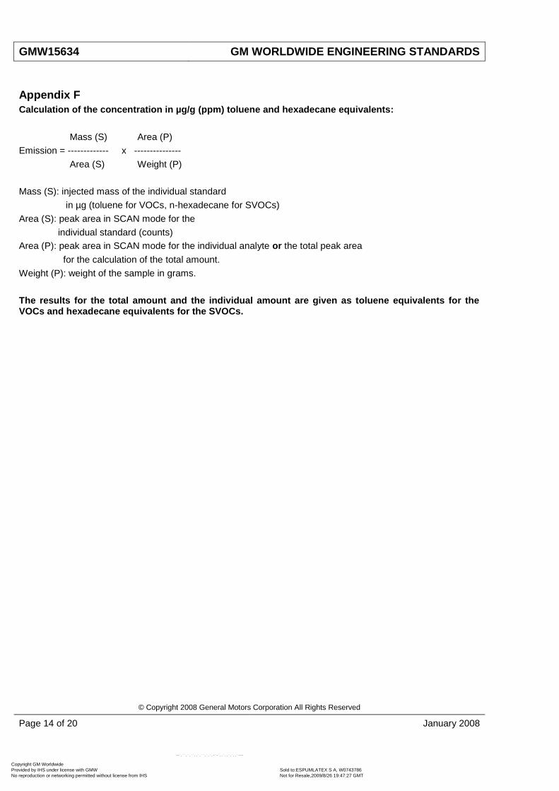
Appendix F
Calculation of the concentration in µg/g (ppm) toluene and hexadecane equivalents:
Mass (S) Area (P)
Emission = ------------- x ---------------
Area (S) Weight (P)
Mass (S): injected mass of the individual standard
in µg (toluene for VOCs, n-hexadecane for SVOCs)
Area (S): peak area in SCAN mode for the
individual standard (counts)
Area (P): peak area in SCAN mode for the individual analyte or the total peak area
for the calculation of the total amount.
Weight (P): weight of the sample in grams.
The results for the total amount and the individual amount are given as toluene equivalents for the VOCs and hexadecane equivalents for the SVOCs.
Copyright GM Worldwide Provided by IHS under license with GMW Sold to:ESPUMLATEX S A, W0743786
Not for Resale,2009/8/26 19:47:27 GMTNo reproduction or networking permitted without license from IHS
--`,``,`,``,,`,``,`,`,-`-`,,`,,`,`,,`---

GM WORLDWIDE ENGINEERING STANDARDS GMW15634
© Copyright 2008 General Motors Corporation All Rights Reserved
January 2008 Page 15 of 20
Appendix G
Data Form G1: Example for Test Result Form for VOCs
Vehicle Interior Material VOC
Laboratory
Order number (internal):
Date of sampling:
Part No.: Total weight of the part in the car:
Supplier: Total size of the part in the car:
Chromatogram
No.: sample 1 sample 2
Data path: Dimension of analysed sample:
Editor: Weight of analysed sample:
Date:
Method:
highest value µg/g
second value µg/g
Sum of the following identified substances in ppm (as toluene equivalent)
Retention
Time (min) RI CAS-No.
Number of
peaks
Single Substance
Area-%
Toluene
Area-% µg/g
Instrumentation used Comments for over all estimationColumn used
Results Single Substances GMW 15634
Sample name: Date of production:
VOC
total
emission
value (µg/g)
substance name
Sum of the identified or dedicated substances
Note: The test result form includes the following information:
Name of the sample
Drawing number
Supplier
Date of production/sampling date
Weight of the sample analysed
Dimensions of the sample analyzed
Dimension of the whole part in the interior
Chromatogram number
Date of analysis
Analysis method
Total VOC and total FOG amount
List of identified analytes and amount
Risk assessment of the results
Copyright GM Worldwide Provided by IHS under license with GMW Sold to:ESPUMLATEX S A, W0743786
Not for Resale,2009/8/26 19:47:27 GMTNo reproduction or networking permitted without license from IHS
--`,``,`,``,,`,``,`,`,-`-`,,`,,`,`,,`---

GMW15634 GM WORLDWIDE ENGINEERING STANDARDS
© Copyright 2008 General Motors Corporation All Rights Reserved
Page 16 of 20 January 2008
Data Form G2: Example for Test Result Form for SVOCs
Vehecle Interior Material SVOC
Laboratory
Order number (internal):
Date of sampling:
Part No.: Total weight of the part in the car:
Supplier: Total size of the part in the car:
Chromatogram
No.: sample 1
Data path: Dimension of analysed sample:
Editor: Weight of analysed sample:
Date:
Method:
highest value µg/g
Sum of the following identified substances in ppm (as n-hexadecane equivalent)
Retention
Time (min) RI CAS-No.
Number of
peaks
Substance Area-
%
n-Hexadecane
Area-% µg/g
Instrumentation used Comments for over all estimationColumn used
Sample name: Date of production:
Results Single Substances GMW 15634
SVOC
total
emission
value (µg/g)
substance name
Sum of the identified or dedicated substances
Note: The test result form includes the following information:
Name of the sample
Drawing number
Supplier
Date of production/sampling date
Weight of the sample analysed
Dimensions of the sample analyzed
Dimension of the whole part in the interior
Chromatogram number
Date of analysis
Analysis method
Total VOC and total FOG amount
List of identified analytes and amount
Risk assessment of the results
Copyright GM Worldwide Provided by IHS under license with GMW Sold to:ESPUMLATEX S A, W0743786
Not for Resale,2009/8/26 19:47:27 GMTNo reproduction or networking permitted without license from IHS
--`,``,`,``,,`,``,`,`,-`-`,,`,,`,`,,`---

GM WORLDWIDE ENGINEERING STANDARDS GMW15634
© Copyright 2008 General Motors Corporation All Rights Reserved
January 2008 Page 17 of 20
Glass Frit
Tenax TA
Glass Wool
SS Screen
Glass Wool
15 m
m60
mm
15 m
m30
mm
133
mm
Glass Frit
Tenax TA
Glass Wool
SS Screen
Glass Wool
15 m
m60
mm
15 m
m30
mm
133
mm
TenaxTA GTDTIM GTDT
Glass Frit
Tenax TA
Glass Wool
SS Screen
Glass Wool
15 m
m60
mm
15 m
m30
mm
133
mm
Glass Frit
Tenax TA
Glass Wool
SS Screen
Glass Wool
15 m
m60
mm
15 m
m30
mm
133
mm
TenaxTA GTDTIM GTDT
Figure G1: Side Profiles of a TenaxTA GlassThermal Desorption Tube (GTDT) and an Interior Materials Glass Thermal Desorption Tube (IM GTDT), Respectively (Not to Actual Scale)
60
mm
Glass Frit
Tenax TA
Glass Wool
He Flow
SS Screen
SLH Adapter (1/2)
He Flow
He Flow
He Flow
Standard InjectionSyringe
Flow Regulator
Gas Meter
SLH Adapter (2/2)
Figure G2: Side Profile of a Gerstel Tube Spiking Septumless Head (SLH) Adapter, with a Helium (He) Flow Meter Connected Upstream, and a Gas Meter Connected Downstream (Not to Actual Scale)
Copyright GM Worldwide Provided by IHS under license with GMW Sold to:ESPUMLATEX S A, W0743786
Not for Resale,2009/8/26 19:47:27 GMTNo reproduction or networking permitted without license from IHS
--`,``,`,``,,`,``,`,`,-`-`,,`,,`,`,,`---

GMW15634 GM WORLDWIDE ENGINEERING STANDARDS
© Copyright 2008 General Motors Corporation All Rights Reserved
Page 18 of 20 January 2008
Figure G3: Merged Total Ion Chromatograms (TICs) of n-C5 to n-C16 VOCs Eluting w/60 m Column (Conditions of VOC run)
Table G1: Corresponding Chromatogram (Figure G3) Retention Times (RT), Compound Names, and Chemical Abstract Services Number (CAS#).
RT (minutes) Compound CAS#
4.59 n-C5 n-pentane 109-66-0
5.95 n-C6 n-hexane 110-54-3
8.54 n-C7 n-heptane 142-82-5
12.65 n-C8 n-octane 111-65-9
17.77 n-C9 n-nonane 111-84-2
22.91 n-C10 n-decane 124-18-5
27.15 n-C11 n-undecane 1120-21-4
30.74 n-C12 n-dodecane 112-40-3
33.85 n-C13 n-tridecane 629-50-5
36.25 n-C14 n-tetradecane 629-59-4
38.16 n-C15 n-pentadecane 629-62-9
39.76 n-C16 n-hexadecane 544-76-3
Copyright GM Worldwide Provided by IHS under license with GMW Sold to:ESPUMLATEX S A, W0743786
Not for Resale,2009/8/26 19:47:27 GMTNo reproduction or networking permitted without license from IHS
--`,``,`,``,,`,``,`,`,-`-`,,`,,`,`,,`---

GM WORLDWIDE ENGINEERING STANDARDS GMW15634
© Copyright 2008 General Motors Corporation All Rights Reserved
January 2008 Page 19 of 20
Figure G4: TIC of n-C16 to n-C32 SVOCs Eluting w/60 m Column (Conditions of FOG Run, Solvent Delay at 13 Minutes)
Table G2: Corresponding Chromatogram (Figure G4) Retention Times, Compound Names, and CAS#
RT (minutes) Compound CAS#
14.05 n-C16 n-hexadecane 544-76-3
15.10 n-C17 n-hexadecane 629-78-7
16.14 n-C18 n-octadecane 593-45-3
17.15 n-C19 n-nonadecane 629-92-5
18.13 n-C20 n-eicosane 112-95-8
19.07 n-C21 n-heneicosane 629-94-7
19.99 n-C22 n-docosane 629-97-0
20.87 n-C23 n-tricosane 638-67-5
21.80 n-C24 n-tetracosane 646-31-1
22.82 n-C25 n-pentacosane 629-99-2
23.96 n-C26 n-hexacosane 630-01-3
25.28 n-C27 n-heptacosane 593-49-7
26.82 n-C28 n-octacosane 630-02-4
28.66 n-C29 n-nonacosane 630-03-5
30.87 n-C30 n-triacontane 638-68-6
33.57 n-C31 n-hentriacotane 630-04-6
36.85 n-C32 n-dotriacontane 544-85-4
Copyright GM Worldwide Provided by IHS under license with GMW Sold to:ESPUMLATEX S A, W0743786
Not for Resale,2009/8/26 19:47:27 GMTNo reproduction or networking permitted without license from IHS
--`,``,`,``,,`,``,`,`,-`-`,,`,,`,`,,`---

GMW15634 GM WORLDWIDE ENGINEERING STANDARDS
© Copyright 2008 General Motors Corporation All Rights Reserved
Page 20 of 20 January 2008
1. sample 2. sample
2 cm away
from the
border
1.
2.
3.
1. sample 2. sample
2 cm away
from the
border
1.
2.
3.
Figure G5: Scheme of Sample Preparation
Copyright GM Worldwide Provided by IHS under license with GMW Sold to:ESPUMLATEX S A, W0743786
Not for Resale,2009/8/26 19:47:27 GMTNo reproduction or networking permitted without license from IHS
--`,``,`,``,,`,``,`,`,-`-`,,`,,`,`,,`---