wpa - leicester ma
TRANSCRIPT

Amec Massachusetts, Inc.Environment & Infrastructure, Inc.271 Mill Road, 3rd FloorChelmsford, MA 01824+1 978-692-9090amecfw.com
Page 1 of 5
May 23, 2017
Town of Leicester Conservation Commission3 Washburn SquareLeicester, MA 01524
Re: Notice of IntentProposed Solar Photovoltaic ProjectStafford Street, Leicester, MA
To the Conservation Commission:
On behalf of Ameresco, Inc. (Ameresco), AMEC Massachusetts, Inc. (AMEC) submits this Notice of Intent (NOI) application package for a proposed 1,359 kilowatt (kW) ground-mounted solar photovoltaic (PV) installation (the Project) off Stafford Street in Leicester (the Project Site). WPA Form 3 is contained in Attachment A. Supporting documents are also attached.
This NOI is being submitted in accordance with the Massachusetts Wetlands Protection Act (WPA) (MGL c. 131 s. 40), its implementing regulations (310 CMR 10.00), and the Town of Leicester Wetlands Protection Bylaw and Regulations. AMEC has determined that filing of this NOI is necessary because portions of the proposed solar array will be located within Buffer Zone to wetland resource areas. The Project will cause no direct impacts to wetlands, and no impacts within the Leicester 25-foot “No Disturb” zone. Construction-period erosion and sediment controls will be employed to prevent sedimentation to jurisdictional areas.
This letter provides a description of the Project, nearby wetland resource areas, and proposed work within Buffer Zones. Figure 1 in Attachment B shows the Project location on a USGS topographic quadrangle map.
Project Description
The Project will be constructed on portions of a 45-acre parcel identified as Assessor’s map and parcel number 34 A3 0, on the north side of Stafford Street near the town boundary with Worcesterand Auburn. The parcel is bisected northwest-southeast by an overhead electric transmission corridor. The parcel and electric transmission corridor are owned by New England Power Company (NEP) d/b/a National Grid. The Project Site is presently predominantly forested. Topography is rolling and slopes down toward the east. Vegetated wetlands and intermittent streams are described below. Photographs are contained in Attachment C.
The Project is a Large-Scale Ground-Mounted Solar Energy System (as defined in the Town of Leicester Solar Bylaw Amendment). The Project will consist of the construction of 5,753 solar PVmodules on approximately 205,642 sq. ft. (4.7 acres) of land as well as 11,923 sq. ft. (0.3 acres)of land for access and the electrical interconnection. Site Plan Drawings are provided in Attachment D.
Access for construction and maintenance will be from a gravel driveway leading from Stafford Street and passing south of an existing solar energy project on the same parcel immediately southwest of the electric transmission corridor. Temporary staging areas for construction equipment and materials for the solar PV installation will be located on existing cleared areas

May 23, 2017
Page 2 of 5
adjacent to the existing solar array. A perimeter security fence will be located a minimum of 25 feet from wetlands and streams, and the array will be set a minimum of 40 feet from wetlands and streams.
The sequence of construction activities will be as follows: establishment of limits of work and placement of perimeter erosion controls marking limits of work; clearing of trees and preparationof the access road from the southwest; tree clearing in the solar array areas; construction of the solar array, appurtenant equipment such as transformer(s), electrical interconnection, and security fence; seeding of all disturbed areas except the access road with an erosion control grass seed mix.
Resource Areas and Jurisdiction
As described above, the site is a forested parcel with rolling topography and an overall slight slope down toward the east toward Kettle Brook approximately one-half mile east of the site. Soils are generally poorly drained and extremely stony. Hydrologically restrictive materials apparently have caused wetlands to form in valleys and saddles. AMEC identified several Bordering Vegetated Wetlands (BVW) and intermittent streams on and near the site. BVWs were delineated in accordance with the Massachusetts Department of Environmental Protection Handbook on Delineating Bordering Vegetated Wetlands under the Massachusetts Wetlands Protection Act.Three wetlands and two intermittent streams whose buffers will be intersected by the project are described herein. BVW Delineation Field Data Forms are contained in Attachment E.
Intermittent Stream A is a broad, rocky surface that shows evidence of water flow by drainage patterns in the leaf litter. The intermittent stream begins at a BVW under the electric transmission lines, enters the forest canopy, and ends at a BVW identified as Wetland 3. Several braided paths lead downslope to Wetland 3. Photo 1 shows Intermittent Stream A.
Wetland 3 is a palustrine forested wetland (PFO) formed in a level area at the base of a trough trending southwest to northeast. Vegetation is dominated by red maple and winterberry. Soils were mucky and extremely stony. Drainage patterns, water-stained leaves, and surface water (several inches) were observed at the time of delineation in March 2017. No evidence of vernal-pool breeding amphibians was observed during multiple site visits in March and April.
In the western corner of the site Wetland 4 is a palustrine scrub-shrub (PSS) wetland within a broad saddle that drains off a plateau toward the north and the east. Wetland 4 transitions to a PFO beneath the forest canopy northeast of the transmission corridor, and drains generally to the north. Vegetation in the PSS part of the wetland is dominated by speckled alder, brambles (rubus species), and unidentified grasses. In the PFO portion vegetation includes red maple, yellow birch, and highbush blueberry.
A small Intermittent Stream C drains from Wetland 4 down toward the east. Intermittent Stream C is similar to Intermittent Stream A with braided channels formed in the leaf litter and between exposed rocks.
Intermittent Stream C drains into a large PFO wetland, Wetland 5, which itself drains offsite to the east. Wetland 5 is forested except at its center, where dense shrubs contribute to the plant community. Vegetation is dominated by red maple, winterberry, and speckled alder. Soils were

May 23, 2017
Page 3 of 5
mucky and extremely stony. Surface water to a depth of several inches was observed at the time of delineation in March 2017. No evidence of vernal-pool breeding amphibians was observed during multiple site visits in March and April.
Approximately 89,300 square feet of Buffer Zone to Wetland 4, Intermittent Stream C, and Wetland 5 on the north side of the project will be impacted by the project. Similarly, approximately 36,300 square feet of Buffer Zone of Intermittent Stream A and Wetland 3 will be impacted on the south side of the proposed solar array. The project will not impact the 25-foot No-Disturb Zone closest to the wetlands. A perimeter erosion control line will be placed at the 25-foot line prior to construction, forming the limit of work, and there will be no clearing or work beyond that line. Impacts between 25 feet and 100 feet from wetland boundaries will be in the form of tree clearing, erection of a chain-link security fence, and solar panel construction.
No other jurisdictional resource areas are located near the Project. No perennial streams, vernal pools, Bordering Land Subject to Flooding, or other resources were observed on or near the site.
Compliance with WPA and Leicester Wetlands Protection Bylaw and Regulations
Massachusetts WPA
The Massachusetts WPA states in 10.02.b, “Any activity other than minor activities identified in 310 CMR 10.02(2)(b)2. proposed or undertaken within 100 feet of an area specified in 310 CMR 10.02(1)(a) (hereinafter called the Buffer Zone) which, in the judgment of the issuing authority, will alter an Area Subject to Protection under M.G.L. c. 131, § 40 is subject to regulation under M.G.L. c. 131, § 40 and requires the filing of a Notice of Intent.” The work area is limited to the Buffer Zone. The work does not qualify as a minor activity identified in 310 CMR 10.02(2)(b)2; and therefore requires the filing of a Notice of Intent. No permanent change in topography will be caused by the Project. The project proposes no direct impacts to wetland resources. No other wetland resource areas or Buffer Zones will be affected by the work.
Leicester Wetlands By-Law
This application is submitted for concurrent review and permitting under the Leicester Wetlands Protection Bylaw and Regulations. The Project proposes no alterations within the 25-foot No Disturb Zone established by the Leicester bylaw and regulations.
Supporting Information
Massachusetts Endangered Species Act Review
According to the Natural Heritage and Endangered Species Program (NHESP) 2008 Priority and Estimated Habitat maps for state-listed protected species, the Project site is not located within any mapped Priority or Estimated Habitats.
Massachusetts Stormwater Standards
The Project is not exempt from the MassDEP Stormwater Management Standards because it is not a single family house, small residential subdivision, or emergency road repair. The required

May 23, 2017
Page 4 of 5
Stormwater Report and Stormwater Checklist are attached to this letter, as specified by WPA Form 3, and are contained in Attachment F. The Stormwater Report was also prepared to meet the requirements of the Leicester Stormwater Regulations.
Other Permits
AMEC has submitted a combined application for Site Plan Review and application for a Special Permit to the Town of Leicester Planning Board.
Filing Requirements
Information required by the Massachusetts and Leicester regulations is contained herein, including as described below.
1. Two (2) copies of a complete NOI application with supporting documents: a. Completed MassDEP WPA Form 3 (Attachment A)b. NOI Wetland Fee Transmittal Form (Attachment A)c. 8 1/2 x 11 inch USGS map or other locus map sufficient to show the location of the
affected area. (Attachment B)d. A detailed written description of work to be performed, to include a description of
existing conditions, proposed conditions, wetland delineation information, stormwater information, construction sequencing, and how project will contribute to the protection of the interest of the Wetlands Protection Act. (this letter)
e. Optional: photographs to help describe the proposed project and wetland impacts (Attachment C)
2. Five (5) sets of plans: 3 full-size (24” x 36”) and 2 half-size (11”x 17” or similar). In all cases, plans shall be of adequate size, scale, and detail to clearly and accurately describe the site, property boundaries, resource area boundaries, extent of the proposed work and potential impacts on resource areas. (Attachment D)
3. Certified Abutters List (abutters to the abutters within 300 feet of the property line of the land where the activity is proposed, including any in another municipality or across a body of water) (Attachment G).
4. Electronic submission of all application materials and plans in .pdf format or other electronic format specified by the Commission. (accompanying this submittal)
5. Filing Fees (MassDEP fee, plus local fees described in Section V.B. of the Regulations). (accompanying this submittal)
We respectfully request the Town of Leicester Conservation Commission consider the information in this Notice of Intent and issue an Order of Conditions permitting the Project as proposed.

May 23, 2017
Page 5 of 5
Should you have any questions regarding this application, please contact us at (978) 392-5307; [email protected] or (978) 392-5370; [email protected].
Thank you.
Sincerely,
AMEC Massachusetts, Inc.
Robert J. Bukowski, P.E. Ryan Hale, PWSProject Manager Permitting Specialist
Attachments
Copy: Ameresco, Inc.

Attachment A
WPA Form 3

wpaform3.doc • rev. 6/28/2016 Page 1 of 9
Massachusetts Department of Environmental ProtectionBureau of Resource Protection - Wetlands
WPA Form 3 – Notice of IntentMassachusetts Wetlands Protection Act M.G.L. c. 131, §40
Provided by MassDEP:
MassDEP File Number
Document Transaction Number
Leicester City/Town
Important:When filling out forms on the computer, use only the tab key to move your cursor - do not use the return key.
Note:Beforecompleting this form consultyour local ConservationCommissionregarding any municipal bylaw or ordinance.
A. General Information
1. Project Location (Note: electronic filers will click on button to locate project site):
0 Stafford Street a. Street Address
Leicester b. City/Town
01611 c. Zip Code
Latitude and Longitude: 42d 13' 42.70" d. Latitude
71d 52' 02.05" e. Longitude
34 A3 0 f. Assessors Map/Plat Number
0g. Parcel /Lot Number
2. Applicant:
Petera. First Name
Esselstyn b. Last Name
Ameresco, Inc. c. Organization
111 Speen Street d. Street Address
Framingham e. City/Town
MA f. State
01701 g. Zip Code
508-498-3083 h. Phone Number
i. Fax Number
[email protected] j. Email Address
3. Property owner (required if different from applicant): Check if more than one owner
Tylera. First Name
Krupa b. Last Name
New England Power Company d/b/a National Grid c. Organization
40 Sylvan Road d. Street Address
Waltham e. City/Town
MA f. State
02451 g. Zip Code
781-907-3906 h. Phone Number
i. Fax Number
[email protected] j. Email address
4. Representative (if any):
Ryana. First Name
Hale b. Last Name
Amec Massachusetts, Inc. c. Company
271 Mill Road d. Street Address
Chelmsford e. City/Town
MAf. State
01824 g. Zip Code
978-392-5370 h. Phone Number
i. Fax Number
[email protected] j. Email address
5. Total WPA Fee Paid (from NOI Wetland Fee Transmittal Form):
500.00 a. Total Fee Paid
237.50 b. State Fee Paid
262.50 c. City/Town Fee Paid

wpaform3.doc • rev. 6/28/2016 Page 2 of 9
Massachusetts Department of Environmental ProtectionBureau of Resource Protection - Wetlands
WPA Form 3 – Notice of IntentMassachusetts Wetlands Protection Act M.G.L. c. 131, §40
Provided by MassDEP:
MassDEP File Number
Document Transaction Number
Leicester City/Town
A. General Information (continued)
6. General Project Description:
Construction of a 1,361 kW ground-mounted solar energy project with portions in buffer zone.
7a. Project Type Checklist: (Limited Project Types see Section A. 7b.)
1. Single Family Home 2. Residential Subdivision
3. Commercial/Industrial 4. Dock/Pier
5. Utilities 6. Coastal engineering Structure
7. Agriculture (e.g., cranberries, forestry) 8. Transportation
9. Other
7b. Is any portion of the proposed activity eligible to be treated as a limited project (including Ecological Restoration Limited Project) subject to 310 CMR 10.24 (coastal) or 310 CMR 10.53 (inland)?
1. Yes No If yes, describe which limited project applies to this project. (See 310 CMR 10.24 and 10.53 for a complete list and description of limited project types)
310 CMR 10.53(3)t. Construction of a new access roadway… renewable energy project. 2. Limited Project Type
If the proposed activity is eligible to be treated as an Ecological Restoration Limited Project (310 CMR10.24(8), 310 CMR 10.53(4)), complete and attach Appendix A: Ecological Restoration Limited Project Checklist and Signed Certification.
8. Property recorded at the Registry of Deeds for:
a. County
b. Certificate # (if registered land)
.c. Book
d. Page Number
B. Buffer Zone & Resource Area Impacts (temporary & permanent)1. Buffer Zone Only – Check if the project is located only in the Buffer Zone of a Bordering Vegetated Wetland, Inland Bank, or Coastal Resource Area. 2. Inland Resource Areas (see 310 CMR 10.54-10.58; if not applicable, go to Section B.3, Coastal Resource Areas).
Check all that apply below. Attach narrative and any supporting documentation describing how the project will meet all performance standards for each of the resource areas altered, including standards requiring consideration of alternative project design or location.

wpaform3.doc • rev. 6/28/2016 Page 3 of 9
Massachusetts Department of Environmental ProtectionBureau of Resource Protection - Wetlands
WPA Form 3 – Notice of IntentMassachusetts Wetlands Protection Act M.G.L. c. 131, §40
Provided by MassDEP:
MassDEP File Number
Document Transaction Number
Leicester City/Town
B. Buffer Zone & Resource Area Impacts (temporary & permanent) (cont’d)
For all projects affecting other Resource Areas, please attach a narrative explaining how the resource area was delineated.
Resource Area Size of Proposed Alteration Proposed Replacement (if any)
a. Bank 1. linear feet
2. linear feet
b. Bordering Vegetated Wetland
1. square feet
2. square feet
c. Land Under Waterbodies and Waterways
1. square feet
2. square feet
3. cubic yards dredged
Resource Area Size of Proposed Alteration Proposed Replacement (if any)
d. Bordering Land Subject to Flooding
1. square feet
2. square feet
3. cubic feet of flood storage lost
4. cubic feet replaced
e. Isolated Land Subject to Flooding
1. square feet
2. cubic feet of flood storage lost
3. cubic feet replaced
f. Riverfront Area 1. Name of Waterway (if available) - specify coastal or inland
2. Width of Riverfront Area (check one):
25 ft. - Designated Densely Developed Areas only
100 ft. - New agricultural projects only
200 ft. - All other projects
3. Total area of Riverfront Area on the site of the proposed project: square feet
4. Proposed alteration of the Riverfront Area:
a. total square feet
b. square feet within 100 ft.
c. square feet between 100 ft. and 200 ft.
5. Has an alternatives analysis been done and is it attached to this NOI? Yes No
6. Was the lot where the activity is proposed created prior to August 1, 1996? Yes No
3. Coastal Resource Areas: (See 310 CMR 10.25-10.35)
Note: for coastal riverfront areas, please complete Section B.2.f. above.

wpaform3.doc • rev. 6/28/2016 Page 4 of 9
Massachusetts Department of Environmental ProtectionBureau of Resource Protection - Wetlands
WPA Form 3 – Notice of IntentMassachusetts Wetlands Protection Act M.G.L. c. 131, §40
Provided by MassDEP:
MassDEP File Number
Document Transaction Number
Leicester City/Town
B. Buffer Zone & Resource Area Impacts (temporary & permanent) (cont’d)
Check all that apply below. Attach narrative and supporting documentation describing how the project will meet all performance standards for each of the resource areas altered, including standards requiring consideration of alternative project design or location.
Online Users: Include your documenttransactionnumber(provided on your receipt page) with all supplementary information you submit to the Department.
Resource Area Size of Proposed Alteration Proposed Replacement (if any)
a. Designated Port Areas Indicate size under Land Under the Ocean, below
b. Land Under the Ocean 1. square feet
2. cubic yards dredged
c. Barrier Beach Indicate size under Coastal Beaches and/or Coastal Dunes below
d. Coastal Beaches 1. square feet
2. cubic yards beach nourishment
e. Coastal Dunes 1. square feet
2. cubic yards dune nourishment
Size of Proposed Alteration Proposed Replacement (if any)
f. Coastal Banks 1. linear feet
g. Rocky Intertidal Shores
1. square feet
h. Salt Marshes 1. square feet
2. sq ft restoration, rehab., creation
i. Land Under Salt Ponds
1. square feet
2. cubic yards dredged
j. Land Containing Shellfish
1. square feet
k. Fish Runs Indicate size under Coastal Banks, inland Bank, Land Under the Ocean, and/or inland Land Under Waterbodies and Waterways, above
1. cubic yards dredged
l. Land Subject to Coastal Storm Flowage
1. square feet
4. Restoration/Enhancement If the project is for the purpose of restoring or enhancing a wetland resource area in addition to the square footage that has been entered in Section B.2.b or B.3.h above, please enter the additional amount here. a. square feet of BVW
b. square feet of Salt Marsh
5. Project Involves Stream Crossings
a. number of new stream crossings
b. number of replacement stream crossings

wpaform3.doc • rev. 6/28/2016 Page 5 of 9
Massachusetts Department of Environmental ProtectionBureau of Resource Protection - Wetlands
WPA Form 3 – Notice of IntentMassachusetts Wetlands Protection Act M.G.L. c. 131, §40
Provided by MassDEP:
MassDEP File Number
Document Transaction Number
Leicester City/Town
C. Other Applicable Standards and Requirements
This is a proposal for an Ecological Restoration Limited Project. Skip Section C and complete Appendix A: Ecological Restoration Limited Project Checklists – Required Actions (310 CMR 10.11).
Streamlined Massachusetts Endangered Species Act/Wetlands Protection Act Review
1. Is any portion of the proposed project located in Estimated Habitat of Rare Wildlife as indicated on the most recent Estimated Habitat Map of State-Listed Rare Wetland Wildlife published by the Natural Heritage and Endangered Species Program (NHESP)? To view habitat maps, see the Massachusetts Natural Heritage Atlas or go to http://maps.massgis.state.ma.us/PRI_EST_HAB/viewer.htm.
a. Yes No If yes, include proof of mailing or hand delivery of NOI to:
Natural Heritage and Endangered Species Program Division of Fisheries and Wildlife 1 Rabbit Hill Road Westborough, MA 01581 2008
b. Date of map
If yes, the project is also subject to Massachusetts Endangered Species Act (MESA) review (321 CMR 10.18). To qualify for a streamlined, 30-day, MESA/Wetlands Protection Act review, please complete Section C.1.c, and include requested materials with this Notice of Intent (NOI); ORcomplete Section C.2.f, if applicable. If MESA supplemental information is not included with the NOI, by completing Section 1 of this form, the NHESP will require a separate MESA filing which may take up to 90 days to review (unless noted exceptions in Section 2 apply, see below).
c. Submit Supplemental Information for Endangered Species Review
1. Percentage/acreage of property to be altered:
(a) within wetland Resource Area percentage/acreage
(b) outside Resource Area percentage/acreage
2. Assessor’s Map or right-of-way plan of site
2. Project plans for entire project site, including wetland resource areas and areas outside of wetlands jurisdiction, showing existing and proposed conditions, existing and proposed tree/vegetation clearing line, and clearly demarcated limits of work
(a) Project description (including description of impacts outside of wetland resource area & buffer zone)
(b) Photographs representative of the site
Some projects not in Estimated Habitat may be located in Priority Habitat, and require NHESP review (see
http://www.mass.gov/eea/agencies/dfg/dfw/natural-heritage/regulatory-review/). Priority Habitat includes habitat for state-listed plants and strictly upland species not protected by the Wetlands Protection Act.
MESA projects may not be segmented (321 CMR 10.16). The applicant must disclose full development plans even if such plans are not required as part of the Notice of Intent process.

wpaform3.doc • rev. 6/28/2016 Page 6 of 9
Massachusetts Department of Environmental ProtectionBureau of Resource Protection - Wetlands
WPA Form 3 – Notice of IntentMassachusetts Wetlands Protection Act M.G.L. c. 131, §40
Provided by MassDEP:
MassDEP File Number
Document Transaction Number
Leicester City/Town
C. Other Applicable Standards and Requirements (cont’d)
(c) MESA filing fee (fee information available at http://www.mass.gov/dfwele/dfw/nhesp/regulatory_review/mesa/mesa_fee_schedule.htm). Make check payable to “Commonwealth of Massachusetts - NHESP” and mail to NHESP at above address
Projects altering 10 or more acres of land, also submit:
(d) Vegetation cover type map of site
(e) Project plans showing Priority & Estimated Habitat boundaries
(f) OR Check One of the Following
1. Project is exempt from MESA review. Attach applicant letter indicating which MESA exemption applies. (See 321 CMR 10.14, http://www.mass.gov/dfwele/dfw/nhesp/regulatory_review/mesa/mesa_exemptions.htm;the NOI must still be sent to NHESP if the project is within estimated habitat pursuant to 310 CMR 10.37 and 10.59.)
2. Separate MESA review ongoing. a. NHESP Tracking #
b. Date submitted to NHESP
3. Separate MESA review completed. Include copy of NHESP “no Take” determination or valid Conservation & Management Permit with approved plan.
3. For coastal projects only, is any portion of the proposed project located below the mean high water line or in a fish run?
a. Not applicable – project is in inland resource area only b. Yes No
If yes, include proof of mailing, hand delivery, or electronic delivery of NOI to either:
South Shore - Cohasset to Rhode Island border, and the Cape & Islands:
Division of Marine Fisheries - Southeast Marine Fisheries Station Attn: Environmental Reviewer1213 Purchase Street – 3rd Floor New Bedford, MA 02740-6694 Email: [email protected]
North Shore - Hull to New Hampshire border:
Division of Marine Fisheries - North Shore OfficeAttn: Environmental Reviewer30 Emerson AvenueGloucester, MA 01930 Email: [email protected]
Also if yes, the project may require a Chapter 91 license. For coastal towns in the Northeast Region, please contact MassDEP’s Boston Office. For coastal towns in the Southeast Region, please contact MassDEP’s Southeast Regional Office.

wpaform3.doc • rev. 6/28/2016 Page 7 of 9
Massachusetts Department of Environmental ProtectionBureau of Resource Protection - Wetlands
WPA Form 3 – Notice of IntentMassachusetts Wetlands Protection Act M.G.L. c. 131, §40
Provided by MassDEP:
MassDEP File Number
Document Transaction Number
Leicester City/Town
C. Other Applicable Standards and Requirements (cont’d)
Online Users:Include your documenttransactionnumber(provided on your receipt page) with all supplementary information you submit to the Department.
4. Is any portion of the proposed project within an Area of Critical Environmental Concern (ACEC)?
a. Yes No If yes, provide name of ACEC (see instructions to WPA Form 3 or MassDEP Website for ACEC locations). Note: electronic filers click on Website.
b. ACEC
5. Is any portion of the proposed project within an area designated as an Outstanding Resource Water (ORW) as designated in the Massachusetts Surface Water Quality Standards, 314 CMR 4.00?
a. Yes No
6. Is any portion of the site subject to a Wetlands Restriction Order under the Inland Wetlands Restriction Act (M.G.L. c. 131, § 40A) or the Coastal Wetlands Restriction Act (M.G.L. c. 130, § 105)?
a. Yes No
7. Is this project subject to provisions of the MassDEP Stormwater Management Standards?
a. Yes. Attach a copy of the Stormwater Report as required by the Stormwater Management Standards per 310 CMR 10.05(6)(k)-(q) and check if:
1. Applying for Low Impact Development (LID) site design credits (as described in Stormwater Management Handbook Vol. 2, Chapter 3)
2. A portion of the site constitutes redevelopment
3. Proprietary BMPs are included in the Stormwater Management System.
b. No. Check why the project is exempt:
1. Single-family house
2. Emergency road repair
3. Small Residential Subdivision (less than or equal to 4 single-family houses or less than or equal to 4 units in multi-family housing project) with no discharge to Critical Areas.
D. Additional Information
This is a proposal for an Ecological Restoration Limited Project. Skip Section D and complete Appendix A: Ecological Restoration Notice of Intent – Minimum Required Documents (310 CMR 10.12).
Applicants must include the following with this Notice of Intent (NOI). See instructions for details.
Online Users: Attach the document transaction number (provided on your receipt page) for any of the following information you submit to the Department.
1. USGS or other map of the area (along with a narrative description, if necessary) containing sufficient information for the Conservation Commission and the Department to locate the site. (Electronic filers may omit this item.)
2. Plans identifying the location of proposed activities (including activities proposed to serve as a Bordering Vegetated Wetland [BVW] replication area or other mitigating measure) relative to the boundaries of each affected resource area.

wpaform3.doc • rev. 6/28/2016 Page 8 of 9
Massachusetts Department of Environmental ProtectionBureau of Resource Protection - Wetlands
WPA Form 3 – Notice of IntentMassachusetts Wetlands Protection Act M.G.L. c. 131, §40
Provided by MassDEP:
MassDEP File Number
Document Transaction Number
LeicesterCity/Town
D. Additional Information (cont’d)
3. Identify the method for BVW and other resource area boundary delineations (MassDEP BVWField Data Form(s), Determination of Applicability, Order of Resource Area Delineation, etc.),
and attach documentation of the methodology.
4. List the titles and dates for all plans and other materials submitted with this NOI.
a. Plan Title
b. Prepared By c. Signed and Stamped by
d. Final Revision Date e. Scale
f. Additional Plan or Document Title g. Date
5. If there is more than one property owner, please attach a list of these property owners notlisted on this form.
6. Attach proof of mailing for Natural Heritage and Endangered Species Program, if needed.
7. Attach proof of mailing for Massachusetts Division of Marine Fisheries, if needed.
8. Attach NOI Wetland Fee Transmittal Form
9. Attach Stormwater Report, if needed.
E. Fees1. Fee Exempt: No filing fee shall be assessed for projects of any city, town, county, or district
of the Commonwealth, federally recognized Indian tribe housing authority, municipal housingauthority, or the Massachusetts Bay Transportation Authority.
Applicants must submit the following information (in addition to pages 1 and 2 of the NOI WetlandFee Transmittal Form) to confirm fee payment:7009382. Municipal Check Number
5/22/20173. Check date
7007214. State Check Number
5/22/20175. Check date
Amec Foster Wheeler Environment & Infrastructure,Inc. 7. Payor name on check: Last Name


noifeetf.doc • Wetland Fee Transmittal Form • rev. 10/11 Page 1 of 2
Massachusetts Department of Environmental ProtectionBureau of Resource Protection - Wetlands NOI Wetland Fee Transmittal FormMassachusetts Wetlands Protection Act M.G.L. c. 131, §40
Important: When filling out forms on the computer, use only the tab key to move your cursor - do not use the return key.
A. Applicant Information
1. Location of Project:
0 Stafford Street a. Street Address
Leicestesr b. City/Town
c. Check number
d. Fee amount
2. Applicant Mailing Address:
Petera. First Name
Esselstyn b. Last Name
Ameresco, Inc. c. Organization
111 Speen Street d. Mailing Address
Framingham e. City/Town
MAf. State
01701 g. Zip Code
508-498-3083 h. Phone Number
i. Fax Number
[email protected] j. Email Address
3. Property Owner (if different):
Tylera. First Name
Krupa b. Last Name
New England Power Company d/b/a National Grid c. Organization
40 Sylvan Road d. Mailing Address
Waltham e. City/Town
MAf. State
02451 g. Zip Code
781-907-3906 h. Phone Number
i. Fax Number
[email protected] j. Email Address
To calculatefiling fees, refer to the category fee list and examples in the instructions for filling out WPA Form 3 (Notice of Intent).
B. Fees Fee should be calculated using the following process & worksheet. Please see Instructions before filling out worksheet.
Step 1/Type of Activity: Describe each type of activity that will occur in wetland resource area and buffer zone.
Step 2/Number of Activities: Identify the number of each type of activity.
Step 3/Individual Activity Fee: Identify each activity fee from the six project categories listed in the instructions.
Step 4/Subtotal Activity Fee: Multiply the number of activities (identified in Step 2) times the fee per category (identified in Step 3) to reach a subtotal fee amount. Note: If any of these activities are in a Riverfront Area in addition to another Resource Area or the Buffer Zone, the fee per activity should be multiplied by 1.5 and then added to the subtotal amount.
Step 5/Total Project Fee: Determine the total project fee by adding the subtotal amounts from Step 4.
Step 6/Fee Payments: To calculate the state share of the fee, divide the total fee in half and subtract $12.50. To calculate the city/town share of the fee, divide the total fee in half and add $12.50.

noifeetf.doc • Wetland Fee Transmittal Form • rev. 10/11 Page 2 of 2
Massachusetts Department of Environmental ProtectionBureau of Resource Protection - Wetlands NOI Wetland Fee Transmittal FormMassachusetts Wetlands Protection Act M.G.L. c. 131, §40
B. Fees (continued) Step 1/Type of Activity Step 2/Number
of Activities Step
3/Individual Activity Fee
Step 4/Subtotal Activity Fee
Electric Generating Facility 1 500 500
Step 5/Total Project Fee: 500
Step 6/Fee Payments:
Total Project Fee: 500a. Total Fee from Step 5
State share of filing Fee: 237.50 b. 1/2 Total Fee less $12.50
City/Town share of filling Fee: 262.50 c. 1/2 Total Fee plus $12.50
C. Submittal Requirements a.) Complete pages 1 and 2 and send with a check or money order for the state share of the fee, payable to
the Commonwealth of Massachusetts.
Department of Environmental Protection Box 4062
Boston, MA 02211
b.) To the Conservation Commission: Send the Notice of Intent or Abbreviated Notice of Intent; a copy ofthis form; and the city/town fee payment.
To MassDEP Regional Office (see Instructions): Send a copy of the Notice of Intent or Abbreviated Notice of Intent; a copy of this form; and a copy of the state fee payment. (E-filers of Notices of Intent may submit these electronically.)

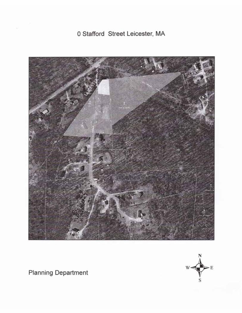
Attachment B
Site Locus

Source: Esri, DigitalGlobe, GeoEye, Earthstar Geographics, CNES/AirbusDS, USDA, USGS, AEX, Getmapping, Aerogrid, IGN, IGP, swisstopo, andthe GIS User Community, Copyright:© 2013 National Geographic Society, i-cubed
H:\Ameresco\Leicester_MA\Task1\MXD\Site Location Map.mxd May 22, 2017 DWN: elizabeth.flanary CHKD: AKN
_̂
Location of Site
FIGURE
1
±
Notes & Sources
AMEC Massachusetts, Inc.271 Mill RoadChelmsford, MA 01824(978) 692-9090
SITE
0 1,000 2,000Feet
SITE LOCATION MAP
Ameresco, Inc.Proposed Photovoltaic
Solar Project
0 Stafford StLeicester, Massachusetts

Attachment C
Photos

PHOTO 1:
Intermittent Stream A View toward East
PHOTO 2:
Wetland 3 View toward East

PHOTO 3:
Wetland 4 PSS section
PHOTO 4:
Wetland 4 PFO section

PHOTO 5:
Intermittent Stream C
PHOTO 6:
Wetland 5

Attachment D
Site Plans

ISSU
ED F
OR
LO
CA
L PE
RM
ITTI
NG
/NO
T FO
R C
ON
STR
UC
TIO
N
1 3C
-501
2
CO
VE
R S
HE
ET
DR
AW
ING
TIT
LE
DR
AW
ING
IND
EX
DR
AW
ING
NU
MB
ER
SH
EE
TN
UM
BE
R
PR
OP
OS
ED
SIT
E P
LAN
CO
NS
TRU
CTI
ON
, ER
OS
ION
AN
D S
ED
IME
NTA
TIO
N C
ON
TRO
L D
ETA
ILS
C-1
01
LOC
US
MA
PN
OT
TO S
CA
LEA
ER
IAL
IMA
GE
SC
ALE
:1" =
100
0'
EX
ISTI
NG
CO
ND
ITIO
NS
PLA
NV
-101
AM
EC
MA
SS
AC
HU
SE
TTS
, IN
C.
271
MIL
L R
OA
DC
HE
LMS
FOR
D, M
AS
SA
CH
US
ETT
S 0
1824
PR
EP
AR
ED
BY
AM
ER
ES
CO
, IN
C.
DE
VE
LOP
ED
BY


Attachment E
Wetland Data Forms

DEP Bordering Vegetated Wetland (310 CMR 10.55) Delineation Field Data FormPlot: W-3 wet plot at flag WA-6Location: National Grid, Parcel 0, Stafford St., Leicester MA Applicant: Ameresco Prepared by: S. Herzog Date: 8 March 2017
Check all that apply: Vegetation alone presumed adequate to delineation BVW boundary: complete Section Ix Vegetation and other indicators of hydrology used to delineate BVW boundary: complete Sections I and II
Method other than dominance test (additional information attached)
Section I. VegetationA. B. C. D.
A. Sample Layer and Plant Species Percent Cover
PercentDominance
DominantPlant
IndicatorCategory
Trees: Red maple (Acer rubrum ) 38 0.49 Yes FACYellow birch (Betula alleghaniensis ) 20 0.26 Yes FACWhite ash (Fraxinus americana ) 20 0.26 Yes FACU
Shrubs: Red maple (Acer rubrum ) 20 0.50 Yes FACWArrowwood (Viburnum recognitum ) 20 0.50 Yes FACW
Herbs: None observed
Vines: None
Asterisks mark wetland indicator plants: species listed in the Wetlands Protection Act; plants in the genus Sphagnum; plants listed as FAC, FAC, FACW, or OBL; or plants with physiological or morphological adaptations as noted.
Vegetation conclusion by dominance test: wetland - 4 dominant hydrophytes; 1 dominant non-hydrophyte
Section II. Indicators of HydrologyHydric Soil Interpretation Other Indicators:
Site inundated: X1. Soil Survey Depth to free water in observation hole:Is there a published soil survey for this site? Yes Depth to soil saturation: 6"
Downloaded from NRCS Web Soil Survey Water marks:Survey area data version 9, Sep 15, 2016 Drift lines:
Soil type mapped: Canton fine sandy loam 8-15% slopes, extremely stony Sediment deposits:Hydric soil inclusions: none reported Drainge patterns in BVW: X
Are field observations consistent with soil survey? No Oxidized rhizospheres:Remarks: soils observed are not well-drained, slopes vary to 15% or > Water-stained leaves: X
Other:2. Soil DescriptionHorizon Depth Matrix color Texture Mottles color Vegetation and Hydrology Conclusions
O 0-2" 7.5YR 3/3 var SL with leaf litter none Number of wetland indicator plantsA 2-8"R 7.5YR 2.5/2 FSL none > number of non-indicator plants: XRefusal on rock 8" Hydric soil present: XMoist, saturated at 6" Other indicators of hydrology: X
Sample location is in a BVW: Yes

DEP Bordering Vegetated Wetland (310 CMR 10.55) Delineation Field Data FormPlot: W-3 upland plot at flag WA-6Location: National Grid, Parcel 0, Stafford St., Leicester MA Applicant: Ameresco Prepared by: S. Herzog Date: 8 March 2017
Check all that apply: Vegetation alone presumed adequate to delineation BVW boundary: complete Section Ix Vegetation and other indicators of hydrology used to delineate BVW boundary: complete Sections I and II
Method other than dominance test (additional information attached)
Section I. VegetationA. B. C. D.
A. Sample Layer and Plant Species Percent Cover
PercentDominance
DominantPlant
IndicatorCategory
Trees: Red oak (Quercus rubra ) 38 0.56 Yes FACUAmerican beech (Fagus grandifolia ) 20 0.29 Yes FACUYellow birch (Betula alleghaniensis ) 10 0.15 No FACW
Shrubs: American beech (Fagus grandifolia ) 20 1.00 Yes FACU
Herbs: None observed
Vines: None
Asterisks mark wetland indicator plants: species listed in the Wetlands Protection Act; plants in the genus Sphagnum; plants listed as FAC, FAC, FACW, or OBL; or plants with physiological or morphological adaptations as noted.
Vegetation conclusion by dominance test: 3 dominant non-wetland; 0 dominant wetland species
Section II. Indicators of HydrologyHydric Soil Interpretation Other Indicators:
Site inundated: 1. Soil Survey Depth to free water in observation hole:Is there a published soil survey for this site? Yes Depth to soil saturation:
Downloaded from NRCS Web Soil Survey Water marks:Survey area data version 9, Sep 15, 2016 Drift lines:
Soil type mapped: Canton fine sandy loam 8-15% slopes, extremely stony Sediment deposits:Hydric soil inclusions: none reported Drainge patterns in BVW:
Are field observations consistent with soil survey? No Oxidized rhizospheres:Remarks: soils observed are not well-drained, slopes vary to 15% or > Water-stained leaves:
Other:2. Soil DescriptionHorizon Depth Matrix color Texture Mottles color Vegetation and Hydrology Conclusions
O 0-2" 7.5YR 3/3 var SL with leaf litter none Number of wetland indicator plantsA 2-8"R 7.5YR 2.5/2 FSL none > number of non-indicator plants: Refusal on rock Hydric soil present:
Other indicators of hydrology: Sample location is in a BVW: No

DEP Bordering Vegetated Wetland (310 CMR 10.55) Delineation Field Data FormPlot: W-4 wet plot at flag WB-10Location: National Grid, Parcel 0, Stafford St., Leicester MA Applicant: Ameresco Prepared by: S. Herzog Date: 8 March 2017
Check all that apply: Vegetation alone presumed adequate to delineation BVW boundary: complete Section Ix Vegetation and other indicators of hydrology used to delineate BVW boundary: complete Sections I and II
Method other than dominance test (additional information attached)
Section I. VegetationA. B. C. D.
A. Sample Layer and Plant Species Percent Cover
PercentDominance
DominantPlant
IndicatorCategory
Trees: None
Shrubs: Speckled Alder (Alnus incana ) 63 0.57 Yes FACWRed osier dogwood (Cornus alba ) 38 0.34 Yes FACWBlackberry sp. (Rubus sp. ) 10 0.09 No FACU
Herbs: None observed
Vines: Grape sp. 10 0.10 No FACU
Asterisks mark wetland indicator plants: species listed in the Wetlands Protection Act; plants in the genus Sphagnum; plants listed as FAC, FAC, FACW, or OBL; or plants with physiological or morphological adaptations as noted.
Vegetation conclusion by dominance test: wetland - 2 dominant hydrophytes; no dominant non-hydrophytes
Section II. Indicators of HydrologyHydric Soil Interpretation Other Indicators:
Site inundated: 1. Soil Survey Depth to free water in observation hole:Is there a published soil survey for this site? Yes Depth to soil saturation: 10"
Downloaded from NRCS Web Soil Survey Water marks:Survey area data version 9, Sep 15, 2016 Drift lines:
Soil type mapped: Canton fine sandy loam 8-15% slopes, extremely stony Sediment deposits:Hydric soil inclusions: none reported Drainge patterns in BVW: X
Are field observations consistent with soil survey? No Oxidized rhizospheres:Remarks: soils observed are not well-drained, slopes vary to 15% or > Water-stained leaves: X
Other:2. Soil DescriptionHorizon Depth Matrix color Texture Mottles color Vegetation and Hydrology Conclusions
A 0-14" 7.5YR 3/1 v dk gr FSiltLoam none Number of wetland indicator plantsA 14-20" 7.5YR 2.5/1 black FSiltLoam none > number of non-indicator plants: XRefusal on rock 8" Hydric soil present: XSaturated at 10" Other indicators of hydrology: X
Sample location is in a BVW: Yes

DEP Bordering Vegetated Wetland (310 CMR 10.55) Delineation Field Data FormPlot: W-4 upland plot at flag WB-10Location: National Grid, Parcel 0, Stafford St., Leicester MA Applicant: Ameresco Prepared by: S. Herzog Date: 8 March 2017
Check all that apply: Vegetation alone presumed adequate to delineation BVW boundary: complete Section Ix Vegetation and other indicators of hydrology used to delineate BVW boundary: complete Sections I and II
Method other than dominance test (additional information attached)
Section I. VegetationA. B. C. D.
A. Sample Layer and Plant Species Percent Cover
PercentDominance
DominantPlant
IndicatorCategory
Trees: None
Shrubs: Blackberry sp. (Rubus sp. ) 63 0.76 Yes FACUStaghorn sumac (Rhus typhina ) 20 0.24 No -
Herbs: Unidentified grass 85 1.00 Yes -
Vines: None
Asterisks mark wetland indicator plants: species listed in the Wetlands Protection Act; plants in the genus Sphagnum; plants listed as FAC, FAC, FACW, or OBL; or plants with physiological or morphological adaptations as noted.
Vegetation conclusion by dominance test: No dominant wetland species
Section II. Indicators of HydrologyHydric Soil Interpretation Other Indicators:
Site inundated: 1. Soil Survey Depth to free water in observation hole:Is there a published soil survey for this site? Yes Depth to soil saturation:
Downloaded from NRCS Web Soil Survey Water marks:Survey area data version 9, Sep 15, 2016 Drift lines:
Soil type mapped: Canton fine sandy loam 8-15% slopes, extremely stony Sediment deposits:Hydric soil inclusions: none reported Drainge patterns in BVW:
Are field observations consistent with soil survey? No Oxidized rhizospheres:Remarks: soils observed are not well-drained, slopes vary to 15% or > Water-stained leaves:
Other:2. Soil DescriptionHorizon Depth Matrix color Texture Mottles color Vegetation and Hydrology Conclusions
A 0-10" 7.5YR 4/4 brown FSL none Number of wetland indicator plantsB 10"-18" 7.5YR 4/6 strong br FSL none > number of non-indicator plants: Refusal on rock 18" Hydric soil present:
Other indicators of hydrology: Sample location is in a BVW: No

DEP Bordering Vegetated Wetland (310 CMR 10.55) Delineation Field Data FormPlot: W-5 wet plot at flag WE-8Location: National Grid, Parcel 0, Stafford St., Leicester MA Applicant: Ameresco Prepared by: S. Herzog Date: 8 March 2017
Check all that apply: Vegetation alone presumed adequate to delineation BVW boundary: complete Section Ix Vegetation and other indicators of hydrology used to delineate BVW boundary: complete Sections I and II
Method other than dominance test (additional information attached)
Section I. VegetationA. B. C. D.
A. Sample Layer and Plant Species Percent Cover
PercentDominance
DominantPlant
IndicatorCategory
Trees: Red maple (Acer rubrum ) 63 0.86 Yes FACWhite ash (Fraxinus americana ) 10 0.14 No FACU
Shrubs: Red maple (Acer rubrum ) 63 0.55 Yes FACWYellow birch (Betula allegheniensis ) 38 0.33 Yes FACWWinterberry (Ilex verticillata ) 10 0.09 No FACUMountain laurel (Kalmia latifolia ) 3 0.03 No FACU
Herbs: Canada mayflower (Maianthemum canadense ) 10 0.63 Yes FACFalse Solomon's seal (Maianthemum racemosum ) 3 0.19 No FACUWhite pine seedlings (Pinus strobus ) 3 0.19 No FACU
Vines: Grape sp. 10 0.10 No FACU
Asterisks mark wetland indicator plants: species listed in the Wetlands Protection Act; plants in the genus Sphagnum; plants listed as FAC, FAC, FACW, or OBL; or plants with physiological or morphological adaptations as noted.
Vegetation conclusion by dominance test: wetland - 4 dominant hydrophytes; no dominant non-hydrophytes
Section II. Indicators of HydrologyHydric Soil Interpretation Other Indicators:
Site inundated: X1. Soil Survey Depth to free water in observation hole:Is there a published soil survey for this site? Yes Depth to soil saturation:
Downloaded from NRCS Web Soil Survey Water marks:Survey area data version 9, Sep 15, 2016 Drift lines:
Soil type mapped: Canton fine sandy loam 8-15% slopes, extremely stony Sediment deposits:Hydric soil inclusions: none reported Drainge patterns in BVW: X
Are field observations consistent with soil survey? No Oxidized rhizospheres:Remarks: soils observed are not well-drained, slopes vary to 15% or > Water-stained leaves: X
Other:2. Soil DescriptionHorizon Depth Matrix color Texture Mottles color Vegetation and Hydrology Conclusions
A 0-5" 7.5YR 2.5/1 black FSiltLoam none Number of wetland indicator plants> number of non-indicator plants: X
Refusal on rock 5" Hydric soil present: XOther indicators of hydrology: XSample location is in a BVW: Yes

DEP Bordering Vegetated Wetland (310 CMR 10.55) Delineation Field Data FormPlot: W-5 upland plot at flag WE-8Location: National Grid, Parcel 0, Stafford St., Leicester MA Applicant: Ameresco Prepared by: S. Herzog Date: 8 March 2017
Check all that apply: Vegetation alone presumed adequate to delineation BVW boundary: complete Section Ix Vegetation and other indicators of hydrology used to delineate BVW boundary: complete Sections I and II
Method other than dominance test (additional information attached)
Section I. VegetationA. B. C. D.
A. Sample Layer and Plant Species Percent Cover
PercentDominance
DominantPlant
IndicatorCategory
Trees: Red oak (Quercus rubra ) 38 0.46 Yes FACUBlack birch (Betula nigra ) 38 0.46 Yes FACUYellow birch (Betula allegheniensis ) 3 0.04 No FACRed maple (Acer rubrum ) 3 0.04 No FAC
Shrubs: Black birch (Betula nigra ) 38 0.54 Yes FACUBlack cherry (Prunus serotina ) 10 0.14 No FACURed maple (Acer rubrum ) 10 0.14 No FACMountain laurel (Kalmia latifolia ) 10 0.14 No FACUYellow birch (Betula allegheniensis ) 3 0.04 No FAC
Herbs: Canada mayflower (Maianthemum canadense ) 10 1.00 Yes FACU
Vines: None
Asterisks mark wetland indicator plants: species listed in the Wetlands Protection Act; plants in the genus Sphagnum; plants listed as FAC, FAC, FACW, or OBL; or plants with physiological or morphological adaptations as noted.
Vegetation conclusion by dominance test: Four dominant upland species, No dominant wetland species
Section II. Indicators of HydrologyHydric Soil Interpretation Other Indicators:
Site inundated: 1. Soil Survey Depth to free water in observation hole:Is there a published soil survey for this site? Yes Depth to soil saturation:
Downloaded from NRCS Web Soil Survey Water marks:Survey area data version 9, Sep 15, 2016 Drift lines:
Soil type mapped: Canton fine sandy loam 8-15% slopes, extremely stony Sediment deposits:Hydric soil inclusions: none reported Drainge patterns in BVW:
Are field observations consistent with soil survey? No Oxidized rhizospheres:Remarks: soils observed are not well-drained, slopes vary to 15% or > Water-stained leaves:
Other:2. Soil DescriptionHorizon Depth Matrix color Texture Mottles color Vegetation and Hydrology Conclusions
A 0-1.5" 2.5YR 3/3 FSL none Number of wetland indicator plantsA2 1.5-6" 10YR 3/4 FSL none > number of non-indicator plants: B 6-9"R 10YR 4/6 FSL none Hydric soil present: Refusal on rock 9" Other indicators of hydrology:
Sample location is in a BVW: No

Attachment F
Stormwater Report

© Amec Foster Wheeler 2017.
Stormwater ReportProposed Photovoltaic Solar ProjectStafford StreetLeicester, Massachusetts
Prepared for:Ameresco, Inc.111 Speen StreetFramingham, MA 01701
Prepared by:AMEC Massachusetts, Inc.
271 Mill Rd, 3rd FloorChelmsford, MA 01824
May 23, 2017
Project number: 3652170091.0300.0002

271 Mill RoadChelmsford, Massachusettsamecfw.com
Stormwater ReportMassDEP Stormwater Report SummaryMassDEP ChecklistStormwater Modeling Report and Summary TableRainfall DataDrainage MapsStormwater CalculationsNRCS Soil Report

MASSACHUSETTS DEPARTMENT OF ENVIRONMENTAL PROTECTION STORMWATER REPORT
Stormwater Management Summary forLeicester, MA Solar PV Array
Standard 1: No New Untreated DischargesThe Massachusetts Stormwater Handbook requires that the project demonstrate that there are no new untreated discharges and that new discharges will not cause erosion or scour to downstream wetlands.
The proposed solar array installation work consists of a concrete equipment pad and ground screw foundation poles installed on the existing ground surface. A permanent gravel road extension is proposed for access to portions of the site. Discharges from access roads are addressed under Standard 8. The Project will not result in any permanent changes to the existing drainage patterns or hydrology; therefore, there will be no new stormwater conveyances or discharges.
Standard 2: Peak Rate AttenuationStandard 2 requires that peak rates of flow be attenuated for the proposed development condition.
This Project will create minimal impervious area. The only new impervious area consists of the ground screw foundation poles installed on the existing ground surface to support the racks and a concrete equipment pad.The access road will be gravel. All other impacted areas will be restored to vegetated ground cover. This Project does not involve any change to existing grades. Attenuation on-site within the large wetlands results in no increase in off-site peak flow or volume.
Standard 3: Stormwater RechargeStandard 3 requires that the infiltration into the ground under post-development conditions is at least as much as the infiltration volume under pre-development conditions.
There will be approximately 6.7 acres of tree clearing for the project. Following tree clearing, the existing ground surface will be restored with grass. The existing stumps and root systems will remain for the majority of the Site except where impeding the ground screw installation. The overall hydrologic conditions, including infiltration into existing rocky soils, are anticipated to remain largely unchanged.
Standard 4: Water QualityStandard 4 requires that all stormwater management systems be designed to remove 80% of the average annual post-construction load of Total Suspended Solids (TSS). The Massachusetts Stormwater Handbook states that this standard is met when:
a. Suitable practices for source control and pollution prevention are identified in a long-term pollution prevention plan, and thereafter are implemented and maintained;
b. Structural stormwater best management practices (BMPs) are sized to capture the required water quality volume as determined in accordance with the Massachusetts Stormwater Handbook; and
c. Pretreatment is provided in accordance with the Massachusetts Stormwater Handbook.
Although tree clearing is proposed, the majority of existing stumps and root systems will remain and will be restored with grass, which will provide stormwater treatment.
Long term pollution prevention planSince no post-construction stormwater BMPs are proposed and there will be no storage of pollutants on the site, a long term pollution prevention plan is not required.
Water quality treatment volumeThe only added impervious area is from the ground screw foundation poles and the concrete equipment pad.
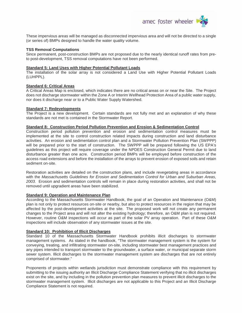
These impervious areas will be managed as disconnected impervious area and will not be directed to a single (or series of) BMPs designed to handle the water quality volume.
TSS Removal ComputationsSince permanent, post-construction BMPs are not proposed due to the nearly identical runoff rates from pre-to post-development, TSS removal computations have not been performed.
Standard 5: Land Uses with Higher Potential Pollutant LoadsThe installation of the solar array is not considered a Land Use with Higher Potential Pollutant Loads (LUHPPL).
Standard 6: Critical AreasA Critical Areas Map is enclosed, which indicates there are no critical areas on or near the Site. The Project does not discharge stormwater within the Zone A or Interim Wellhead Protection Area of a public water supply, nor does it discharge near or to a Public Water Supply Watershed.
Standard 7: RedevelopmentsThe Project is a new development. Certain standards are not fully met and an explanation of why these standards are not met is contained in the Stormwater Report.
Standard 8: Construction Period Pollution Prevention and Erosion & Sedimentation ControlConstruction period pollution prevention and erosion and sedimentation control measures must be implemented at the site to control construction related impacts during construction and land disturbance activities. An erosion and sedimentation control plan and a Stormwater Pollution Prevention Plan (SWPPP) will be prepared prior to the start of construction. The SWPPP will be prepared following the US EPA’s guidelines as this project will require coverage under the NPDES Construction General Permit due to land disturbance greater than one acre. Construction period BMPs will be employed before construction of the access road extensions and before the installation of the arrays to prevent erosion of exposed soils and retain sediment on-site.
Restoration activities are detailed on the construction plans, and include revegetating areas in accordance with the Massachusetts Guidelines for Erosion and Sedimentation Control for Urban and Suburban Areas, 2003. Erosion and sedimentation controls will remain in place during restoration activities, and shall not be removed until upgradient areas have been stabilized.
Standard 9: Operation and Maintenance PlanAccording to the Massachusetts Stormwater Handbook, the goal of an Operation and Maintenance (O&M) plan is not only to protect resources on-site or nearby, but also to protect resources in the region that may be affected by the post-development activities at the site. The proposed work will not create any permanent changes to the Project area and will not alter the existing hydrology; therefore, an O&M plan is not required. However, routine O&M inspections will occur as part of the solar PV array operation. Part of these O&M inspections will include observation of any stormwater issues at the site.
Standard 10: Prohibition of Illicit DischargesStandard 10 of the Massachusetts Stormwater Handbook prohibits illicit discharges to stormwater management systems. As stated in the handbook, “The stormwater management system is the system for conveying, treating, and infiltrating stormwater on-site, including stormwater best management practices and any pipes intended to transport stormwater to the groundwater, a surface water, or municipal separate storm sewer system. Illicit discharges to the stormwater management system are discharges that are not entirely comprised of stormwater.”
Proponents of projects within wetlands jurisdiction must demonstrate compliance with this requirement by submitting to the issuing authority an Illicit Discharge Compliance Statement verifying that no illicit discharges exist on the site, and by including in the pollution prevention plan measures to prevent illicit discharges to the stormwater management system. Illicit discharges are not applicable to this Project and an Illicit Discharge Compliance Statement is not required.

Leicester Stormwater - MassDEP Checklist.docx • 04/01/08 Stormwater Report Checklist • Page 1 of 8
Massachusetts Department of Environmental Protection Bureau of Resource Protection - Wetlands Program
Checklist for Stormwater Report A. Introduction
Important: When filling out forms on the computer, use only the tab key to move your cursor - do not use the return key.
A Stormwater Report must be submitted with the Notice of Intent permit application to document compliance with the Stormwater Management Standards. The following checklist is NOT a substitute for the Stormwater Report (which should provide more substantive and detailed information) but is offered here as a tool to help the applicant organize their Stormwater Management documentation for their Report and for the reviewer to assess this information in a consistent format. As noted in the Checklist, the Stormwater Report must contain the engineering computations and supporting information set forth in Volume 3 of the Massachusetts Stormwater Handbook. The Stormwater Report must be prepared and certified by a Registered Professional Engineer (RPE) licensed in the Commonwealth.
The Stormwater Report must include:The Stormwater Checklist completed and stamped by a Registered Professional Engineer (see page 2) that certifies that the Stormwater Report contains all required submittals.1 This Checklist is to be used as the cover for the completed Stormwater Report.Applicant/Project NameProject AddressName of Firm and Registered Professional Engineer that prepared the ReportLong-Term Pollution Prevention Plan required by Standards 4-6Construction Period Pollution Prevention and Erosion and Sedimentation Control Plan required by Standard 82
Operation and Maintenance Plan required by Standard 9
In addition to all plans and supporting information, the Stormwater Report must include a brief narrative describing stormwater management practices, including environmentally sensitive site design and LID techniques, along with a diagram depicting runoff through the proposed BMP treatment train. Plans are required to show existing and proposed conditions, identify all wetland resource areas, NRCS soil types, critical areas, Land Uses with Higher Potential Pollutant Loads (LUHPPL), and any areas on the site where infiltration rate is greater than 2.4 inches per hour. The Plans shall identify the drainage areas for both existing and proposed conditions at a scale that enables verification of supporting calculations.
As noted in the Checklist, the Stormwater Management Report shall document compliance with each of the Stormwater Management Standards as provided in the Massachusetts Stormwater Handbook. The soils evaluation and calculations shall be done using the methodologies set forth in Volume 3 of the Massachusetts Stormwater Handbook.
To ensure that the Stormwater Report is complete, applicants are required to fill in the Stormwater Report Checklist by checking the box to indicate that the specified information has been included in the Stormwater Report. If any of the information specified in the checklist has not been submitted, the applicant must provide an explanation. The completed Stormwater Report Checklist and Certification must be submitted with the Stormwater Report.
1 The Stormwater Report may also include the Illicit Discharge Compliance Statement required by Standard 10. If not included inthe Stormwater Report, the Illicit Discharge Compliance Statement must be submitted prior to the discharge of stormwater runoff to the post-construction best management practices.
2 For some complex projects, it may not be possible to include the Construction Period Erosion and Sedimentation Control Plan inthe Stormwater Report. In that event, the issuing authority has the discretion to issue an Order of Conditions that approves the project and includes a condition requiring the proponent to submit the Construction Period Erosion and Sedimentation Control Plan before commencing any land disturbance activity on the site.


Leicester Stormwater - MassDEP Checklist.docx • 04/01/08 Stormwater Report Checklist • Page 3 of 8
Massachusetts Department of Environmental Protection Bureau of Resource Protection - Wetlands Program
Checklist for Stormwater Report Checklist (continued)
LID Measures: Stormwater Standards require LID measures to be considered. Document what environmentally sensitive design and LID Techniques were considered during the planning and design of the project:
No disturbance to any Wetland Resource Areas
Site Design Practices (e.g. clustered development, reduced frontage setbacks)
Reduced Impervious Area (Redevelopment Only)
Minimizing disturbance to existing trees and shrubs
LID Site Design Credit Requested:
Credit 1
Credit 2
Credit 3
Use of “country drainage” versus curb and gutter conveyance and pipe
Bioretention Cells (includes Rain Gardens)
Constructed Stormwater Wetlands (includes Gravel Wetlands designs)
Treebox Filter
Water Quality Swale
Grass Channel
Green Roof
Other (describe): Vegetated ground cover
Standard 1: No New Untreated Discharges
No new untreated discharges
Outlets have been designed so there is no erosion or scour to wetlands and waters of theCommonwealth
Supporting calculations specified in Volume 3 of the Massachusetts Stormwater Handbook included.

Leicester Stormwater - MassDEP Checklist.docx • 04/01/08 Stormwater Report Checklist • Page 4 of 8
Massachusetts Department of Environmental Protection Bureau of Resource Protection - Wetlands Program
Checklist for Stormwater Report Checklist (continued)
Standard 2: Peak Rate Attenuation
Standard 2 waiver requested because the project is located in land subject to coastal storm flowage and stormwater discharge is to a wetland subject to coastal flooding.Evaluation provided to determine whether off-site flooding increases during the 100-year 24-hour storm.
Calculations provided to show that post-development peak discharge rates do not exceed pre-development rates for the 2-year and 10-year 24-hour storms. If evaluation shows that off-site flooding increases during the 100-year 24-hour storm, calculations are also provided to show that post-development peak discharge rates do not exceed pre-development rates for the 100-year 24-hour storm.
Standard 3: Recharge
Soil Analysis provided.
Required Recharge Volume calculation provided.
Required Recharge volume reduced through use of the LID site Design Credits.
Sizing the infiltration, BMPs is based on the following method: Check the method used.
Static Simple Dynamic Dynamic Field1
Runoff from all impervious areas at the site discharging to the infiltration BMP.
Runoff from all impervious areas at the site is not discharging to the infiltration BMP and calculations are provided showing that the drainage area contributing runoff to the infiltration BMPs is sufficient to generate the required recharge volume.
Recharge BMPs have been sized to infiltrate the Required Recharge Volume.
Recharge BMPs have been sized to infiltrate the Required Recharge Volume only to the maximum extent practicable for the following reason:
Site is comprised solely of C and D soils and/or bedrock at the land surface
M.G.L. c. 21E sites pursuant to 310 CMR 40.0000
Solid Waste Landfill pursuant to 310 CMR 19.000
Project is otherwise subject to Stormwater Management Standards only to the maximum extent practicable.
Calculations showing that the infiltration BMPs will drain in 72 hours are provided.
Property includes a M.G.L. c. 21E site or a solid waste landfill and a mounding analysis is included.
1 80% TSS removal is required prior to discharge to infiltration BMP if Dynamic Field method is used.

Leicester Stormwater - MassDEP Checklist.docx • 04/01/08 Stormwater Report Checklist • Page 5 of 8
Massachusetts Department of Environmental Protection Bureau of Resource Protection - Wetlands Program
Checklist for Stormwater Report Checklist (continued)
Standard 3: Recharge (continued)
The infiltration BMP is used to attenuate peak flows during storms greater than or equal to the 10-year 24-hour storm and separation to seasonal high groundwater is less than 4 feet and a mounding analysis is provided.
Documentation is provided showing that infiltration BMPs do not adversely impact nearby wetland resource areas.
Standard 4: Water Quality
The Long-Term Pollution Prevention Plan typically includes the following:Good housekeeping practices;Provisions for storing materials and waste products inside or under cover;Vehicle washing controls;Requirements for routine inspections and maintenance of stormwater BMPs;Spill prevention and response plans;Provisions for maintenance of lawns, gardens, and other landscaped areas;Requirements for storage and use of fertilizers, herbicides, and pesticides;Pet waste management provisions;Provisions for operation and management of septic systems;Provisions for solid waste management;Snow disposal and plowing plans relative to Wetland Resource Areas;Winter Road Salt and/or Sand Use and Storage restrictions;Street sweeping schedules;Provisions for prevention of illicit discharges to the stormwater management system;Documentation that Stormwater BMPs are designed to provide for shutdown and containment in theevent of a spill or discharges to or near critical areas or from LUHPPL;Training for staff or personnel involved with implementing Long-Term Pollution Prevention Plan;List of Emergency contacts for implementing Long-Term Pollution Prevention Plan.
A Long-Term Pollution Prevention Plan is attached to Stormwater Report and is included as anattachment to the Wetlands Notice of Intent.Treatment BMPs subject to the 44% TSS removal pretreatment requirement and the one inch rule forcalculating the water quality volume are included, and discharge:
is within the Zone II or Interim Wellhead Protection Area
is near or to other critical areas
is within soils with a rapid infiltration rate (greater than 2.4 inches per hour)
involves runoff from land uses with higher potential pollutant loads.
The Required Water Quality Volume is reduced through use of the LID site Design Credits.
Calculations documenting that the treatment train meets the 80% TSS removal requirement and, if applicable, the 44% TSS removal pretreatment requirement, are provided.
Leicester Stormwater - MassDEP Checklist.docx • 04/01/08 Stormwater Report Checklist • Page 6 of 8
Massachusetts Department of Environmental Protection Bureau of Resource Protection - Wetlands Program
Checklist for Stormwater Report Checklist (continued)
Standard 4: Water Quality (continued)
The BMP is sized (and calculations provided) based on:
The ½” or 1” Water Quality Volume or
The equivalent flow rate associated with the Water Quality Volume and documentation is provided showing that the BMP treats the required water quality volume.
The applicant proposes to use proprietary BMPs, and documentation supporting use of proprietary BMP and proposed TSS removal rate is provided. This documentation may be in the form of the propriety BMP checklist found in Volume 2, Chapter 4 of the Massachusetts Stormwater Handbook and submitting copies of the TARP Report, STEP Report, and/or other third party studies verifying performance of the proprietary BMPs.
A TMDL exists that indicates a need to reduce pollutants other than TSS and documentation showing that the BMPs selected are consistent with the TMDL is provided.
Standard 5: Land Uses With Higher Potential Pollutant Loads (LUHPPLs)
The NPDES Multi-Sector General Permit covers the land use and the Stormwater Pollution Prevention Plan (SWPPP) has been included with the Stormwater Report.The NPDES Multi-Sector General Permit covers the land use and the SWPPP will be submitted prior to the discharge of stormwater to the post-construction stormwater BMPs.
The NPDES Multi-Sector General Permit does not cover the land use.
LUHPPLs are located at the site and industry specific source control and pollution prevention measures have been proposed to reduce or eliminate the exposure of LUHPPLs to rain, snow, snow melt and runoff, and been included in the long term Pollution Prevention Plan.
All exposure has been eliminated.
All exposure has not been eliminated and all BMPs selected are on MassDEP LUHPPL list.
The LUHPPL has the potential to generate runoff with moderate to higher concentrations of oil and grease (e.g. all parking lots with >1000 vehicle trips per day) and the treatment train includes an oil grit separator, a filtering bioretention area, a sand filter or equivalent.
Standard 6: Critical Areas
The discharge is near or to a critical area and the treatment train includes only BMPs that MassDEP has approved for stormwater discharges to or near that particular class of critical area.
Critical areas and BMPs are identified in the Stormwater Report.

Leicester Stormwater - MassDEP Checklist.docx • 04/01/08 Stormwater Report Checklist • Page 7 of 8
Massachusetts Department of Environmental Protection Bureau of Resource Protection - Wetlands Program
Checklist for Stormwater Report Checklist (continued)
Standard 7: Redevelopments and Other Projects Subject to the Standards only to the maximum extent practicable
The project is subject to the Stormwater Management Standards only to the maximum Extent Practicable as a:
Limited Project
Small Residential Projects: 5-9 single family houses or 5-9 units in a multi-family development provided there is no discharge that may potentially affect a critical area.Small Residential Projects: 2-4 single family houses or 2-4 units in a multi-family development with a discharge to a critical areaMarina and/or boatyard provided the hull painting, service and maintenance areas are protected from exposure to rain, snow, snow melt and runoff
Bike Path and/or Foot Path
Redevelopment Project
Redevelopment portion of mix of new and redevelopment.
Certain standards are not fully met (Standard No. 1, 8, 9, and 10 must always be fully met) and an explanation of why these standards are not met is contained in the Stormwater Report.The project involves redevelopment and a description of all measures that have been taken to improve existing conditions is provided in the Stormwater Report. The redevelopment checklist found in Volume 2 Chapter 3 of the Massachusetts Stormwater Handbook may be used to document that the proposed stormwater management system (a) complies with Standards 2, 3 and the pretreatment and structural BMP requirements of Standards 4-6 to the maximum extent practicable and (b) improves existing conditions.
Standard 8: Construction Period Pollution Prevention and Erosion and Sedimentation Control
A Construction Period Pollution Prevention and Erosion and Sedimentation Control Plan must include the following information:
Narrative;Construction Period Operation and Maintenance Plan;Names of Persons or Entity Responsible for Plan Compliance;Construction Period Pollution Prevention Measures;Erosion and Sedimentation Control Plan Drawings;Detail drawings and specifications for erosion control BMPs, including sizing calculations;Vegetation Planning;Site Development Plan;Construction Sequencing Plan;Sequencing of Erosion and Sedimentation Controls;Operation and Maintenance of Erosion and Sedimentation Controls;Inspection Schedule;Maintenance Schedule;Inspection and Maintenance Log Form.
A Construction Period Pollution Prevention and Erosion and Sedimentation Control Plan containing the information set forth above has been included in the Stormwater Report.

Leicester Stormwater - MassDEP Checklist.docx • 04/01/08 Stormwater Report Checklist • Page 8 of 8
Massachusetts Department of Environmental Protection Bureau of Resource Protection - Wetlands Program
Checklist for Stormwater Report Checklist (continued)
Standard 8: Construction Period Pollution Prevention and Erosion and Sedimentation Control(continued)
The project is highly complex and information is included in the Stormwater Report that explains why it is not possible to submit the Construction Period Pollution Prevention and Erosion and Sedimentation Control Plan with the application. A Construction Period Pollution Prevention and Erosion and Sedimentation Control has not been included in the Stormwater Report but will be submitted before land disturbance begins.
The project is not covered by a NPDES Construction General Permit.
The project is covered by a NPDES Construction General Permit and a copy of the SWPPP is in the Stormwater Report.The project is covered by a NPDES Construction General Permit but no SWPPP been submitted. The SWPPP will be submitted BEFORE land disturbance begins.
Standard 9: Operation and Maintenance Plan
The Post Construction Operation and Maintenance Plan is included in the Stormwater Report and includes the following information:
Name of the stormwater management system owners;
Party responsible for operation and maintenance;
Schedule for implementation of routine and non-routine maintenance tasks;
Plan showing the location of all stormwater BMPs maintenance access areas;
Description and delineation of public safety features;
Estimated operation and maintenance budget; and
Operation and Maintenance Log Form.
The responsible party is not the owner of the parcel where the BMP is located and the Stormwater Report includes the following submissions:
A copy of the legal instrument (deed, homeowner’s association, utility trust or other legal entity) that establishes the terms of and legal responsibility for the operation and maintenance of the project site stormwater BMPs;
A plan and easement deed that allows site access for the legal entity to operate and maintain BMP functions.
Standard 10: Prohibition of Illicit Discharges
The Long-Term Pollution Prevention Plan includes measures to prevent illicit discharges;
An Illicit Discharge Compliance Statement is attached;
NO Illicit Discharge Compliance Statement is attached but will be submitted prior to the discharge of any stormwater to post-construction BMPs.


STORMWATER REPORT
Stormwater Modeling
The stormwater runoff pattern for the Leicester site will not be altered for this Project. The site is anexisting wooded area where tree clearing and minimal site grading is proposed. Surface drainage from the site is conveyed over the existing wooded areas from west to east to two on-site wetlands to the north and south. The titles of Wetland 5 (north) and Wetland 3 (south) have been retained in this stormwater report to coincide with the existing wetlands delineation.
Runoff calculations were performed for the Soil Conservation Service (SCS) Type III 2- and 10-year, 24-hour storm events. The documented rainfall was estimated from the Northeast Regional Climate Center (NRCC) Extreme Precipitation Tables to be 3.24 and 4.86 inches for the 2- and 10-year storm events, respectively.
The existing and proposed condition peak-design flows were assessed using the National Resources Conservation Service (NRCS) Technical Release 55 (TR-55) methodology. Autodesk® Storm and Sanitary Analysis 2015 stormwater modeling software was used. The software program is included in the AutoCAD Civil 3D package that utilizes the TR-55 methodology. It is a comprehensive hydrodynamic modeling program which analyzes and designs site hydrology, surface drainage systems, and storm drains. It can manage a variety of flow situations such as overland flow, drainage swales, ponds, and piping systems.
The existing conditions topography is from a field survey performed by AMEC in March 2017. This topography was used to develop the stormwater model. There were two scenarios evaluated: the Existing Condition (pre-PV array development) and the Proposed Condition (post-PV array development). The detailed stormwater model, NRCS Soil Report, and the NRCC precipitation table for Leicester, MA are enclosed.
The primary impact of the solar PV array on the stormwater runoff rate and volume is a result of the ground screw foundation poles of the rack assembly and tree clearing to eliminate shading of the array. There will be a total of 156 panel rack assemblies. Each of these rack assemblies require four ground screw posts to anchor them to the ground (624 total ground screws). The ground screw diameter used for this project is 4 inches.
In addition to the ground screws, there will be a concrete equipment pad for the required electrical connection of the solar array. The equipment pad size used in this stormwater analysis is 28.5 feet wide by 48 feet long.
There will be approximately 6.7 acres of tree clearing for the project. Following tree clearing, the existing ground surface will be restored with grass. The existing stumps and root systems will remain for the majority of the Site except where impeding the ground screw installation. A proposed gravel access road will extend from the existing gravel area adjacent to the existing solar site located to the south of the proposed project. The proposed gravel access road is approximately 16 feet wide and 760 feet long and includes upgrading the existing gravel area east of the existing solar site. With the exception of the ground screws, concrete equipment pad, and gravel access road, all disturbed areas will be restored with vegetated ground cover.
The impervious cover associated with the proposed ground screws and equipment pad accounts for approximately 0.3% of the affected drainage sub-basin area (see summary table enclosed). Also represented in the summary table are the existing and proposed conditions for peak runoff rate and volume for the 2- and 10-year 24-hour storm events.

The peak flow rates and total runoff volume to the existing wetlands increase slightly under the proposed condition; however, further attenuation on-site within the large wetlands results in no increase in off-site peak flow or volume. As a result, the model shows that there is no change in off-site conditions.
Stormwater Erosion Control Plan
A Stormwater Erosion Control Plan will be implemented prior to and during construction. This plan will address all potential avenues and pathways for erosion during construction and operation. This section briefly describes what the erosion control plan will encompass.
The primary construction activities that the plan will address will include: the cutting of trees in the existing wooded areas; the addition of gravel fill material for the proposed gravel road construction; the movement of heavy machinery; and re-vegetation of disturbed areas (if required). Vegetative cover outside of the limit of disturbance is to remain. If the vegetative cover outside the intended work area is damaged or disturbed during construction, it will be repaired to re-establish vegetation. Erosion control measures will be installed at the perimeter of the work to prevent sediment from leaving the site. Material stockpiles, if required, will be maintained in one or more central locations. Perimeter erosion control will placed around all stockpiles and will consist of sediment barriers sufficient enough to contain sediment.
Disturbance of the existing ground surface and access road by equipment is another possible source of erosion during construction. Rutting or exposed soil will require repair and attempts to mitigate future rutting at the same location will be made. Avoiding site work on-site during periods of heavy precipitation or when the cover soils are saturated and soft should mitigate many of the issues related to equipment use on-site.
The lower edge of each panel array, or the “drip edge,” has been identified as a potential source of ongoing erosion. This is not likely to be an issue due to the relatively short drip distance and the proposed vegetative cover. If erosion along the drip edge becomes an issue it will be mitigated as part of ongoing maintenance at the landfill, likely with a gravel splash strip or erosion control blanket.

LEICESTER, MA - SOLAR PV DEVELOPMENT
Ground Screw Area 0.09 sf Equipment Pad Area 1368 sf
Condition Gravel Woods Brush Grass
Sub-basinTotal Area
(acres) # Screws
Total Ground Screw Area
(acre)1Total Gravel Area (acre)
Woods Area (acre)
Brush Area (acre)
Grass Area (acre)
A 5.36 0.00 3.71 1.65 0.00
B 6.05 0.29 3.03 2.73 0.00TOTAL 11.41 0.29 6.74 4.38 0.00
A 5.36 296 0.032 0.06 0.00 1.65 3.62
B 6.05 328 0.001 0.35 0.00 2.73 2.97TOTAL 11.41 624 0.033 0.42 0.00 4.38 6.58
624 Total ground screws0.3% Increase in impervious area due to ground screws
and equipment pad.1. Ground screw area includes concrete equipment pad.
2 0.36 0.64 0.28 1.09 1.48 0.3910 3.01 4.11 1.10 4.23 5.03 0.802 0.46 0.67 0.21 1.30 1.60 0.30
10 3.70 4.61 0.91 4.92 5.54 0.62
2 0.00 0.00 0.00
10 0.00 0.00 0.002 0.00 0.00 0.0010 0.00 0.00 0.00
Outlet A
Outlet B
Existing Condition
Runoff Volume (ac-in)
Proposed Condition
Runoff Volume (ac-in)
Difference in Runoff
Volume (ac-in)
OFF-SITE SUMMARY FLOW
Outfall24-hour Storm
Event
Existing Condition Peak
Flow (cfs)
Proposed Condition Peak
Flow (cfs)
Difference in Peak Flow
(cfs)
Sub-basin24-hour Storm
Event
Existing Condition Peak
Flow (cfs)
Proposed Condition Peak
Flow (cfs)
Difference in Peak Flow
(cfs)
Sub-basin A
Sub-basin B
Sub-basin Ground Screws
ON-SITE SUMMARY FLOW VOLUME
EXISTING
PROPOSED

Extreme Precipitation TablesNortheast Regional Climate CenterData represents point estimates calculated from partial duration series. All precipitation amounts are displayed in inches.
Smoothing YesState Massachusetts
LocationLongitude 71.884 degrees WestLatitude 42.212 degrees NorthElevation 0 feetDate/Time Mon, 22 May 2017 17:32:53 -0400
Extreme Precipitation Estimates 5min 10min 15min 30min 60min 120min 1hr 2hr 3hr 6hr 12hr 24hr 48hr 1day 2day 4day 7day 10day
1yr 0.28 0.42 0.53 0.69 0.86 1.09 1yr 0.75 1.07 1.27 1.61 2.06 2.64 2.91 1yr 2.34 2.79 3.19 3.87 4.48 1yr2yr 0.35 0.53 0.66 0.88 1.10 1.39 2yr 0.95 1.27 1.61 2.03 2.56 3.24 3.50 2yr 2.86 3.37 3.87 4.59 5.22 2yr5yr 0.41 0.63 0.80 1.07 1.36 1.74 5yr 1.18 1.57 2.03 2.56 3.23 4.08 4.46 5yr 3.61 4.29 4.91 5.75 6.47 5yr10yr 0.46 0.72 0.91 1.24 1.61 2.07 10yr 1.39 1.85 2.42 3.07 3.86 4.86 5.36 10yr 4.30 5.15 5.88 6.82 7.61 10yr25yr 0.54 0.86 1.09 1.50 1.99 2.59 25yr 1.72 2.29 3.04 3.87 4.89 6.14 6.84 25yr 5.43 6.58 7.46 8.56 9.43 25yr50yr 0.60 0.97 1.24 1.74 2.35 3.09 50yr 2.03 2.70 3.64 4.64 5.85 7.33 8.24 50yr 6.49 7.92 8.94 10.17 11.11 50yr
100yr 0.69 1.12 1.44 2.03 2.77 3.66 100yr 2.39 3.17 4.33 5.53 6.99 8.76 9.93 100yr 7.75 9.55 10.72 12.08 13.08 100yr200yr 0.78 1.27 1.65 2.36 3.27 4.35 200yr 2.82 3.74 5.16 6.62 8.36 10.46 11.98 200yr 9.26 11.52 12.85 14.36 15.40 200yr500yr 0.93 1.53 2.00 2.90 4.07 5.47 500yr 3.51 4.65 6.51 8.37 10.59 13.26 15.38 500yr 11.73 14.79 16.35 18.06 19.13 500yr
Lower Confidence Limits 5min 10min 15min 30min 60min 120min 1hr 2hr 3hr 6hr 12hr 24hr 48hr 1day 2day 4day 7day 10day
1yr 0.21 0.32 0.39 0.53 0.65 0.99 1yr 0.56 0.97 1.09 1.46 1.83 2.27 2.50 1yr 2.01 2.40 2.70 3.27 4.13 1yr2yr 0.34 0.52 0.64 0.87 1.08 1.25 2yr 0.93 1.23 1.44 1.89 2.43 3.14 3.39 2yr 2.78 3.26 3.75 4.44 5.04 2yr5yr 0.38 0.59 0.74 1.01 1.28 1.49 5yr 1.11 1.46 1.70 2.23 2.85 3.81 4.15 5yr 3.37 3.99 4.56 5.29 5.94 5yr
10yr 0.42 0.65 0.81 1.13 1.45 1.70 10yr 1.26 1.66 1.93 2.51 3.20 4.40 4.84 10yr 3.90 4.65 5.27 6.05 6.70 10yr25yr 0.48 0.74 0.92 1.31 1.72 2.02 25yr 1.49 1.97 2.28 2.96 3.74 5.35 5.94 25yr 4.74 5.71 6.40 7.25 7.87 25yr50yr 0.53 0.81 1.01 1.45 1.96 2.29 50yr 1.69 2.24 2.60 3.35 4.21 6.22 6.96 50yr 5.51 6.69 7.43 8.32 8.90 50yr
100yr 0.59 0.89 1.12 1.62 2.22 2.61 100yr 1.92 2.55 2.96 3.79 4.74 7.25 8.18 100yr 6.41 7.87 8.65 9.57 10.06 100yr200yr 0.65 0.99 1.25 1.81 2.52 2.98 200yr 2.18 2.92 3.37 4.31 5.35 8.45 9.67 200yr 7.48 9.30 10.09 11.00 11.38 200yr500yr 0.78 1.16 1.49 2.17 3.08 3.56 500yr 2.66 3.48 4.02 5.13 6.29 10.37 12.11 500yr 9.17 11.64 12.41 13.30 13.37 500yr
Upper Confidence Limits 5min 10min 15min 30min 60min 120min 1hr 2hr 3hr 6hr 12hr 24hr 48hr 1day 2day 4day 7day 10day
1yr 0.31 0.48 0.58 0.78 0.96 1.18 1yr 0.83 1.15 1.36 1.77 2.33 2.89 3.15 1yr 2.56 3.03 3.47 4.17 4.81 1yr2yr 0.36 0.56 0.69 0.94 1.15 1.34 2yr 1.00 1.31 1.53 2.01 2.59 3.34 3.64 2yr 2.96 3.50 4.02 4.77 5.44 2yr5yr 0.43 0.67 0.83 1.14 1.45 1.72 5yr 1.25 1.69 1.99 2.56 3.23 4.38 4.81 5yr 3.87 4.62 5.28 6.24 7.05 5yr10yr 0.50 0.77 0.96 1.34 1.73 2.09 10yr 1.49 2.05 2.41 3.09 3.85 5.36 5.93 10yr 4.74 5.70 6.49 7.65 8.56 10yr25yr 0.62 0.95 1.18 1.68 2.21 2.70 25yr 1.91 2.64 3.12 3.94 4.86 7.01 7.84 25yr 6.20 7.54 8.53 10.00 11.12 25yr50yr 0.73 1.11 1.38 1.98 2.67 3.28 50yr 2.30 3.21 3.81 4.74 5.78 8.59 9.68 50yr 7.60 9.30 10.49 12.27 13.56 50yr
100yr 0.86 1.30 1.62 2.34 3.22 3.98 100yr 2.77 3.89 4.63 5.72 6.90 10.52 11.94 100yr 9.31 11.49 12.89 15.01 16.53 100yr200yr 1.01 1.52 1.92 2.78 3.88 4.84 200yr 3.35 4.73 5.64 6.87 8.22 12.90 14.75 200yr 11.41 14.18 15.81 18.38 20.17 200yr500yr 1.29 1.92 2.48 3.60 5.11 6.26 500yr 4.41 6.12 7.31 8.78 10.36 16.85 19.44 500yr 14.91 18.70 20.71 24.00 26.21 500yr
2yr
24hr
3.24
10yr 4.86

EX
ISTI
NG
SO
LAR
SIT
E
OHE
OHE
OHE
OHE
OHE
OHE
OHE
OHE
OHE
OHE
OHE
OHE
OHE
OHE
OHE
OHE
OHE
OHE
OHE
OHE
OHE
OHE
OHE
OHE
SD
ZOZO
ZO
ZO
ZO
ZO
ZOZO
ZO
ZOZO
ZOZO
ZOZO
ZO ZO
ZO
ZO
ZO
ZO
ZO
ZO
ZOZO
ZO
ZOZO
ZOZO
ZO
ZOZO
ZOZO
ZOZO
ZO
ZO
ZO
ZO
ZO
ZO
ZO
ZO
ZOZO
ZOZO
ZOZO
ZOZO
ZOZO
AB
AN
DO
NE
DU
TIL.
PO
LES
IRF
IPF
IPF
DH
F
DH
F
DH
F
12" H
DP
EIN
V. 8
09.0
'
EX
ISTI
NG
GR
AV
EL
EN
TRA
NC
E
ZO
ZO
EX
ISTI
NG
TR
AIL
SUBR
UBAN-A
GRICULT
URAL Z
ONE
RESID
ENTI
AL-1
ZONE
BUSI
NESS
RESID
ENTI
AL-1
ZONE
BUSI
NESS
INDUST
RIAL-
A ZO
NE
EX
ISTI
NG
GR
AV
EL
EN
TRA
NC
E
EX
ISTI
NG
GA
TE
EX
ISTI
NG
TRA
IL
INTE
RM
ITTE
NT
STR
EA
M C
ZO
ZO
ED
GE
OF
PA
VE
ME
NT
STAF
FORD S
TREE
T
RIP
RA
P
12" H
DP
E
WE
TLA
ND
4
WE
TLA
ND
5
WE
TLA
ND
3
INTE
RM
ITTE
NT
STR
EA
M A
SU
B-B
AS
IN A
SU
B-B
AS
IN B
WE
TLA
ND
5
WE
TLA
ND
3
OU
TLE
T A
OU
TLE
T B
MA
JOR
CO
NTO
UR
MIN
OR
CO
NTO
UR
PR
OP
ER
TY L
INE
ZO10
0' P
RO
PE
RTY
LIN
E O
FFS
ET
WE
TLA
ND
LIN
E
25' W
ETL
AN
D L
INE
BU
FFE
R (N
O D
ISTU
RB
)10
0' W
ETL
AN
D L
INE
BU
FFE
RTR
AIL
FEN
CE
WE
TLA
ND
FLA
G W
ITH
IDE
NTI
FIE
R
STO
NE
WA
LL
ZON
ING
DIS
TRIC
T B
OU
ND
AR
Y L
INE
250'
PO
WE
R L
INE
RIG
HT-
OF-
WA
Y
AP
PR
OX
IMA
TE A
BU
TTE
RS
PR
OP
ER
TY L
INE
DH
F
TRE
E L
INE
DR
ILL
HO
LE F
OU
ND
TRA
NS
MIS
SIO
N L
INE
TO
WE
R
OH
EO
VE
RH
EA
D E
LEC
TRIC
LIN
EU
TILI
TY P
OLE
SU
RV
EY
MO
NU
ME
NT
FOU
ND
IPF/
IRF
GU
Y
SU
B-B
AS
IN B
OU
ND
AR
YS
UB
-BA
SIN
NA
ME
DE
SIG
N M
OD
EL
NO
DE
TIM
E O
F C
ON
CE
NTR
ATI
ON
FLO
W D
IRE
CTI
ON
LEG
EN
D:
SC
ALE
:
DR
AW
ING
NU
MB
ER
:
SH
EE
T N
UM
BE
R:
APPROVED ISSUED BY REVISIONISSUE / REVISION DESCRIPTION DATE
PR
OJE
CT
NU
MB
ER
:
DE
SIG
NE
D B
Y:
DR
AW
N B
Y:
CH
EC
KE
D B
Y:
U:\- CAD Projects\Ameresco\NGRID\Leicester - 3652170091\7.0 CAD\7.1 Design - Permitting\Figures\Leicester Stormwater-Pre 5-22-17.dwg - SW-101 - May. 23, 2017 1:40pm - andrew.vardakis
3652
1700
91
AS
SH
OW
N
DE
D
UN
LES
S O
THE
RW
ISE
AG
RE
ED
IN A
WR
ITTE
N C
ON
TRA
CT
BE
TWE
EN
AM
EC
FO
STE
R W
HE
ELE
R A
ND
ITS
CLI
EN
T: (I
) TH
IS D
OC
UM
EN
T C
ON
TAIN
S IN
FOR
MA
TIO
N, D
ATA
AN
D D
ES
IGN
TH
AT
IS C
ON
FID
EN
TIA
L A
ND
MA
Y N
OT
BE
CO
PIE
D O
R D
ISC
LOS
ED
; AN
D (I
I) TH
IS D
OC
UM
EN
T M
AY
ON
LY B
E U
SE
D B
Y T
HE
CLI
ENT
IN T
HE
CO
NTE
XT
AN
D F
OR
TH
E E
XP
RE
SS
PU
RP
OS
E F
OR
WH
ICH
IT H
AS
BE
EN
DE
LIV
ER
ED
. AN
Y O
THE
R U
SE
OR
RE
LIA
NC
E O
N T
HIS
DO
CU
ME
NT
BY
AN
Y T
HIR
D P
AR
TY IS
AT
THA
T P
AR
TY'S
SO
LE R
ISK
AN
D R
ES
PO
NS
IBIL
ITY
.
DA
A
AP
V
APV DAA 0ISSUED FOR LOCAL PERMITTING/NOT FOR CONSTRUCTION 05/23/2017

EX
ISTI
NG
SO
LAR
SIT
E
OHE
OHE
OHE
OHE
OHE
OHE
OHE
OHE
OHE
OHE
OHE
OHE
OHE
OHE
OHE
OHE
OHE
OHE
OHE
OHE
OHE
OHE
OHE
OHE
SD
ZOZO
ZO
ZO
ZO
ZO
ZOZO
ZO
ZOZO
ZOZO
ZOZO
ZO ZO
ZO
ZO
ZO
ZO
ZO
ZO
ZOZO
ZO
ZOZO
ZOZO
ZO
ZOZO
ZOZO
ZOZO
ZO
ZO
ZO
ZO
ZO
ZO
ZO
ZO
ZOZO
ZOZO
ZOZO
ZOZO
ZOZO
AB
AN
DO
NE
DU
TIL.
PO
LES
IRF
IPF
IPF
DH
F
DH
F
DH
F
12" H
DP
EIN
V. 8
09.0
'
EX
ISTI
NG
GR
AV
EL
EN
TRA
NC
E
ZO
ZO
EX
ISTI
NG
TR
AIL
SUBR
UBAN-A
GRICULT
URAL Z
ONE
RESID
ENTI
AL-1
ZONE
BUSI
NESS
RESID
ENTI
AL-1
ZONE
BUSI
NESS
INDUST
RIAL-
A ZO
NE
EX
ISTI
NG
GR
AV
EL
EN
TRA
NC
E
EX
ISTI
NG
GA
TE
EX
ISTI
NG
TRA
IL
INTE
RM
ITTE
NT
STR
EA
M C
ZO
ZO
ED
GE
OF
PA
VE
ME
NT
STAF
FORD S
TREE
T
RIP
RA
P
12" H
DP
E
WE
TLA
ND
4
WE
TLA
ND
5
WE
TLA
ND
3
INTE
RM
ITTE
NT
STR
EA
M A
X
XX
X
X
X
X
X
X
X
X
X
X
X
X
X
XX
XX
XX
X
X
X
X
X
X
X
X
X
X
X
X
X
X
X
UGE
UGE
UGE
UGEUGE
UGE
UGE
UGE
UGE
UGE
UGEUGE
TC
TC
TC
TC
TC
TC
TC
TCTC
TC
TC
TC
TCTC
TCTC
TC
TC
TC
TC
TC
TC
TC
TC
PR
OP
OS
ED
GR
AV
EL
RO
AD
NE
W R
ISE
R P
OLE
NE
W R
EC
LOS
ER
PO
LE
PR
OP
OS
ED
AC
CE
SS
GA
TE
2C
-501
SB
SB
SB
SB
SB
SB
SB
SB
SB
SB
SB
SB
SB
SB
SB
SB
SB
SB
SB
SBSBSB
SBSB
SB
SBSB
SB
SB
SBSB
SBSBSB
SB
PR
OP
OS
ED
CO
NS
TRU
CTI
ON
EN
TRA
NC
E
PR
OP
OS
ED
INTE
RC
ON
NE
CTI
ON
PO
INT
TO E
XIS
TIN
G P
OLE
4C
-501
OHW
SU
B-B
AS
IN A
SU
B-B
AS
IN B
OU
TLE
T A
OU
TLE
T B
WE
TLA
ND
5
WE
TLA
ND
3
MA
JOR
CO
NTO
UR
MIN
OR
CO
NTO
UR
PR
OP
ER
TY L
INE
ZO10
0' P
RO
PE
RTY
LIN
E O
FFS
ET
WE
TLA
ND
LIN
E
25' W
ETL
AN
D L
INE
BU
FFE
R (N
O D
ISTU
RB
)10
0' W
ETL
AN
D L
INE
BU
FFE
RTR
AIL
FEN
CE
WE
TLA
ND
FLA
G
STO
NE
WA
LL
ZON
ING
DIS
TRIC
T B
OU
ND
AR
Y L
INE
250'
PO
WE
R L
INE
RIG
HT-
OF-
WA
Y
AP
PR
OX
IMA
TE A
BU
TTE
RS
PR
OP
ER
TY L
INE
DH
F
TRE
E L
INE
DR
ILL
HO
LE F
OU
ND
PR
OP
OS
ED
TR
EE
CLE
AR
ING
LIN
ETC
PR
OP
OS
ED
FE
NC
EX
PR
OP
OS
ED
UN
DE
RG
RO
UN
D E
LEC
TRIC
UG
E
PR
OP
OS
ED
SE
DIM
EN
T B
AR
RIE
RS
B
TRA
NS
MIS
SIO
N L
INE
TO
WE
R
OH
EO
VE
RH
EA
D E
LEC
TRIC
LIN
EU
TILI
TY P
OLE
SU
RV
EY
MO
NU
ME
NT
FOU
ND
IPF/
IRF
GU
Y
PR
OP
OS
ED
EQ
UIP
ME
NT
PA
D
PR
OP
OS
ED
OV
ER
HE
AD
ELE
CTR
ICO
HW
PR
OP
OS
ED
5x5
SO
LAR
PA
NE
L R
AC
K
PR
OP
OS
ED
5x4
SO
LAR
PA
NE
L R
AC
K
SU
B-B
AS
IN B
OU
ND
AR
YS
UB
-BA
SIN
NA
ME
DE
SIG
N M
OD
EL
NO
DE
TIM
E O
F C
ON
CE
NTR
ATI
ON
FLO
W D
IRE
CTI
ON
LEG
EN
D:
SC
ALE
:
DR
AW
ING
NU
MB
ER
:
SH
EE
T N
UM
BE
R:
APPROVED ISSUED BY REVISIONISSUE / REVISION DESCRIPTION DATE
PR
OJE
CT
NU
MB
ER
:
DE
SIG
NE
D B
Y:
DR
AW
N B
Y:
CH
EC
KE
D B
Y:
U:\- CAD Projects\Ameresco\NGRID\Leicester - 3652170091\7.0 CAD\7.1 Design - Permitting\Figures\Leicester Stormwater-Post 5-22-17.dwg - SW-102 - May. 23, 2017 1:38pm - andrew.vardakis
3652
1700
91
AS
SH
OW
N
DE
D
UN
LES
S O
THE
RW
ISE
AG
RE
ED
IN A
WR
ITTE
N C
ON
TRA
CT
BE
TWE
EN
AM
EC
FO
STE
R W
HE
ELE
R A
ND
ITS
CLI
EN
T: (I
) TH
IS D
OC
UM
EN
T C
ON
TAIN
S IN
FOR
MA
TIO
N, D
ATA
AN
D D
ES
IGN
TH
AT
IS C
ON
FID
EN
TIA
L A
ND
MA
Y N
OT
BE
CO
PIE
D O
R D
ISC
LOS
ED
; AN
D (I
I) TH
IS D
OC
UM
EN
T M
AY
ON
LY B
E U
SE
D B
Y T
HE
CLI
ENT
IN T
HE
CO
NTE
XT
AN
D F
OR
TH
E E
XP
RE
SS
PU
RP
OS
E F
OR
WH
ICH
IT H
AS
BE
EN
DE
LIV
ER
ED
. AN
Y O
THE
R U
SE
OR
RE
LIA
NC
E O
N T
HIS
DO
CU
ME
NT
BY
AN
Y T
HIR
D P
AR
TY IS
AT
THA
T P
AR
TY'S
SO
LE R
ISK
AN
D R
ES
PO
NS
IBIL
ITY
.
DA
A
AP
V
APV DAA 0ISSUED FOR LOCAL PERMITTING/NOT FOR CONSTRUCTION 05/23/2017

Aut
odes
k St
orm
and
San
itary
Ana
lysi
sLe
ices
ter,
MA
Sol
ar S
torm
wat
er R
epor
tA
utod
esk
Stor
m a
nd S
anita
ry A
naly
sis
Leic
este
r, M
A S
olar
Sto
rmw
ater
Rep
ort

Leicester, MA SolarPre-Development
2-Year StormProject DescriptionLeicester Stormwater Model-Pre.SPF
Project OptionsCFSElevationSCS TR-55SCS TR-55Kinematic WaveYESYES
Analysis OptionsMay 22, 2017 00:00:00May 23, 2017 00:00:00May 22, 2017 00:00:000 days0 01:00:00 days hh:mm:ss0 00:05:00 days hh:mm:ss0 00:05:00 days hh:mm:ss30 seconds
Number of ElementsQty12402002200002000
Rainfall DetailsSN Rain Gage Data Data Source Rainfall Rain State County Return Rainfall Rainfall
ID Source ID Type Units Period Depth Distribution(years) (inches)
1 Leicester Time Series 2-year Cumulative inches Massachusetts Worcester 2 3.24 SCS Type III 24-hr
Land Uses ...................................................
Pipes .................................................. Pumps ................................................ Orifices ............................................... Weirs .................................................. Outlets ................................................Pollutants ....................................................
Outfalls ............................................... Flow Diversions .................................. Inlets ................................................... Storage Nodes ...................................Links............................................................. Channels ............................................
Reporting Time Step ...................................Routing Time Step ......................................
Rain Gages .................................................Subbasins....................................................Nodes........................................................... Junctions ............................................
Start Analysis On ........................................End Analysis On ..........................................Start Reporting On ......................................Antecedent Dry Days ..................................Runoff (Dry Weather) Time Step ................Runoff (Wet Weather) Time Step ...............
Elevation Type ............................................Hydrology Method .......................................Time of Concentration (TOC) Method ........Link Routing Method ...................................Enable Overflow Ponding at Nodes ............Skip Steady State Analysis Time Periods ...
File Name ....................................................Description ..................................................
Leicester, MA Solar
Stormwater Report
Flow Units ...................................................

Leicester, MA SolarPre-Development
2-Year StormSubbasin SummarySN Subbasin Area Weighted Total Total Total Peak Time of
ID Curve Rainfall Runoff Runoff Runoff ConcentrationNumber Volume
(ac) (in) (in) (ac-in) (cfs) (days hh:mm:ss)1 Sub-basin A 5.36 52.85 3.24 0.20 1.09 0.36 0 00:10:342 Sub-basin B 6.05 53.28 3.24 0.22 1.30 0.46 0 00:09:22

Leicester, MA SolarPre-Development
2-Year StormNode SummarySN Element Element Invert Ground/Rim Initial Surcharge Ponded Peak Max HGL Max Min Time of Total Total Time
ID Type Elevation (Max) Water Elevation Area Inflow Elevation Surcharge Freeboard Peak Flooded FloodedElevation Elevation Attained Depth Attained Flooding Volume
Attained Occurrence(ft) (ft) (ft) (ft) (ft²) (cfs) (ft) (ft) (ft) (days hh:mm) (ac-in) (min)
1 Out-A Outfall 761.00 0.00 761.002 Out-B Outfall 741.00 0.00 741.003 Wetland 3 Storage Node 748.00 754.00 748.00 20178.00 0.46 748.23 0.00 0.004 Wetland 5 Storage Node 784.00 790.00 784.00 72180.00 0.36 784.05 0.00 0.00

Lei
cest
er, M
A So
lar
Pre-
Dev
elop
men
t2-
Year
Sto
rmLi
nk S
umm
ary
SNEl
emen
tEl
emen
tFr
omTo
(Out
let)
Leng
thIn
let
Out
let
Aver
age
Dia
met
er o
rM
anni
ng's
Peak
Des
ign
Flow
Peak
Flo
w/
Peak
Flo
wPe
ak F
low
Peak
Flo
wTo
tal T
ime
Rep
orte
dID
Type
(Inle
t)N
ode
Inve
rtIn
vert
Slop
eH
eigh
tR
ough
ness
Flow
Cap
acity
Des
ign
Flow
Velo
city
Dep
thD
epth
/Su
rcha
rged
Con
ditio
nN
ode
Elev
atio
nEl
evat
ion
Rat
ioTo
tal D
epth
Rat
io(ft
)(ft
)(ft
)(%
)(in
)(c
fs)
(cfs
)(ft
/sec
)(ft
)(m
in)
1W
eir-
AW
eir
Wet
land
5O
ut-A
784.
0076
1.00
0.00
2W
eir-
BW
eir
Wet
land
3O
ut-B
748.
0074
1.00
0.00

Leicester, MA SolarPre-Development
2-Year StormSubbasin Hydrology
Subbasin : Sub-basin A
Input Data
Area (ac) ........................................................................ 5.36Weighted Curve Number ............................................... 52.85Rain Gage ID ................................................................. Leicester
Composite Curve Number Area Soil CurveSoil/Surface Description (acres) Group NumberGravel roads 0.00 B 85.00Woods, Good 3.71 B 55.00Brush, Good 1.65 B 48.00Meadow, non-grazed 0.00 B 58.00Composite Area & Weighted CN 5.36 52.85
Time of Concentration
TOC Method : SCS TR-55
Sheet Flow Equation :
Tc = (0.007 * ((n * Lf)^0.8)) / ((P^0.5) * (Sf^0.4))
Where :
Tc = Time of Concentration (hr) n = Manning's roughness Lf = Flow Length (ft) P = 2 yr, 24 hr Rainfall (inches) Sf = Slope (ft/ft)
Shallow Concentrated Flow Equation :
V = 16.1345 * (Sf^0.5) (unpaved surface) V = 20.3282 * (Sf^0.5) (paved surface) V = 15.0 * (Sf^0.5) (grassed waterway surface) V = 10.0 * (Sf^0.5) (nearly bare & untilled surface) V = 9.0 * (Sf^0.5) (cultivated straight rows surface) V = 7.0 * (Sf^0.5) (short grass pasture surface) V = 5.0 * (Sf^0.5) (woodland surface) V = 2.5 * (Sf^0.5) (forest w/heavy litter surface) Tc = (Lf / V) / (3600 sec/hr)
Where:
Tc = Time of Concentration (hr) Lf = Flow Length (ft) V = Velocity (ft/sec) Sf = Slope (ft/ft)
Channel Flow Equation :
V = (1.49 * (R^(2/3)) * (Sf^0.5)) / n R = Aq / Wp Tc = (Lf / V) / (3600 sec/hr)
Where :
Tc = Time of Concentration (hr) Lf = Flow Length (ft) R = Hydraulic Radius (ft) Aq = Flow Area (ft²) Wp = Wetted Perimeter (ft) V = Velocity (ft/sec) Sf = Slope (ft/ft) n = Manning's roughness

Leicester, MA SolarPre-Development
2-Year StormSubarea Subarea Subarea
Sheet Flow Computations A B C Manning's Roughness : .4 0.00 0.00 Flow Length (ft) : 100 0.00 0.00 Slope (%) : 4 0.00 0.00 2 yr, 24 hr Rainfall (in) : 3.24 0.00 0.00 Velocity (ft/sec) : 0.10 0.00 0.00 Computed Flow Time (min) : 16.17 0.00 0.00
Subarea Subarea SubareaShallow Concentrated Flow Computations A B C Flow Length (ft) : 60 228 0.00 Slope (%) : 11 12 0.00 Surface Type : Woodland Forest Unpaved Velocity (ft/sec) : 1.66 0.87 0.00 Computed Flow Time (min) : 0.60 4.37 0.00Total TOC (min) ..................10.57
Subbasin Runoff Results
Total Rainfall (in) ............................................................ 3.24Total Runoff (in) ............................................................. 0.20Peak Runoff (cfs) ........................................................... 0.36Weighted Curve Number ............................................... 52.85Time of Concentration (days hh:mm:ss) ........................ 0 00:10:34

Leicester, MA SolarPre-Development
2-Year Storm
Subbasin : Sub-basin A

Leicester, MA SolarPre-Development
2-Year Storm Subbasin : Sub-basin B
Input Data
Area (ac) ........................................................................ 6.05Weighted Curve Number ............................................... 53.28Rain Gage ID ................................................................. Leicester
Composite Curve Number Area Soil CurveSoil/Surface Description (acres) Group NumberGravel roads 0.29 B 85.00Woods, Good 3.03 B 55.00Brush, Good 2.73 B 48.00Meadow, non-grazed 0.00 B 58.00Composite Area & Weighted CN 6.05 53.28
Time of Concentration
Subarea Subarea SubareaSheet Flow Computations A B C Manning's Roughness : .4 0.00 0.00 Flow Length (ft) : 100 0.00 0.00 Slope (%) : 7 0.00 0.00 2 yr, 24 hr Rainfall (in) : 3.24 0.00 0.00 Velocity (ft/sec) : 0.13 0.00 0.00 Computed Flow Time (min) : 12.93 0.00 0.00
Subarea Subarea SubareaShallow Concentrated Flow Computations A B C Flow Length (ft) : 213 236 0.00 Slope (%) : 14.5 16 0.00 Surface Type : Woodland Forest Unpaved Velocity (ft/sec) : 1.90 1.00 0.00 Computed Flow Time (min) : 1.87 3.93 0.00Total TOC (min) ..................9.37
Subbasin Runoff Results
Total Rainfall (in) ............................................................ 3.24Total Runoff (in) ............................................................. 0.22Peak Runoff (cfs) ........................................................... 0.46Weighted Curve Number ............................................... 53.28Time of Concentration (days hh:mm:ss) ........................ 0 00:09:22

Leicester, MA SolarPre-Development
2-Year Storm
Subbasin : Sub-basin B

Leicester, MA SolarPre-Development
2-Year StormStorage Nodes
Storage Node : Wetland 3
Input Data
748.00754.006.00748.000.0020178.000.00
Outflow Weirs
SN Element Weir Flap Crest Crest Length Weir Total DischargeID Type Gate Elevation Offset Height Coefficient
(ft) (ft) (ft) (ft)1 Weir-B Rectangular No 754.00 6.00 100.00 1.00 3.33
Output Summary Results
0.460.460.000.00748.230.23748.080.081 00:000.000000.00
Total Time Flooded (min) ....................................Total Retention Time (sec) ..................................
Max HGL Depth Attained (ft) ...............................Average HGL Elevation Attained (ft) ....................Average HGL Depth Attained (ft) .........................Time of Max HGL Occurrence (days hh:mm) ......Total Exfiltration Volume (1000-ft³) ......................Total Flooded Volume (ac-in) ..............................
Evaporation Loss .................................................
Peak Inflow (cfs) ..................................................Peak Lateral Inflow (cfs) ......................................Peak Outflow (cfs) ...............................................Peak Exfiltration Flow Rate (cfm) ........................Max HGL Elevation Attained (ft) ..........................
Invert Elevation (ft) ...............................................Max (Rim) Elevation (ft) .......................................Max (Rim) Offset (ft) ............................................Initial Water Elevation (ft) .....................................Initial Water Depth (ft) ..........................................Ponded Area (ft²) .................................................

Leicester, MA SolarPre-Development
2-Year Storm Storage Node : Wetland 5
Input Data
784.00790.006.00784.000.0072180.000.00
Outflow Weirs
SN Element Weir Flap Crest Crest Length Weir Total DischargeID Type Gate Elevation Offset Height Coefficient
(ft) (ft) (ft) (ft)1 Weir-A Rectangular No 790.00 6.00 100.00 1.00 3.33
Output Summary Results
0.360.360.000.00784.050.05784.020.021 00:000.000000.00
Total Exfiltration Volume (1000-ft³) ......................Total Flooded Volume (ac-in) ..............................Total Time Flooded (min) ....................................Total Retention Time (sec) ..................................
Peak Exfiltration Flow Rate (cfm) ........................Max HGL Elevation Attained (ft) ..........................Max HGL Depth Attained (ft) ...............................Average HGL Elevation Attained (ft) ....................Average HGL Depth Attained (ft) .........................Time of Max HGL Occurrence (days hh:mm) ......
Initial Water Depth (ft) ..........................................Ponded Area (ft²) .................................................Evaporation Loss .................................................
Peak Inflow (cfs) ..................................................Peak Lateral Inflow (cfs) ......................................Peak Outflow (cfs) ...............................................
Invert Elevation (ft) ...............................................Max (Rim) Elevation (ft) .......................................Max (Rim) Offset (ft) ............................................Initial Water Elevation (ft) .....................................

Leicester, MA SolarPre-Development
10-Year StormProject DescriptionLeicester Stormwater Model-Pre.SPF
Project OptionsCFSElevationSCS TR-55SCS TR-55Kinematic WaveYESYES
Analysis OptionsMay 22, 2017 00:00:00May 23, 2017 00:00:00May 22, 2017 00:00:000 days0 01:00:00 days hh:mm:ss0 00:05:00 days hh:mm:ss0 00:05:00 days hh:mm:ss30 seconds
Number of ElementsQty12402002200002000
Rainfall DetailsSN Rain Gage Data Data Source Rainfall Rain State County Return Rainfall Rainfall
ID Source ID Type Units Period Depth Distribution(years) (inches)
1 Leicester Time Series 10-year Cumulative inches Massachusetts Worcester 10 4.86 SCS Type III 24-hr
Land Uses ...................................................
Pipes .................................................. Pumps ................................................ Orifices ............................................... Weirs .................................................. Outlets ................................................Pollutants ....................................................
Outfalls ............................................... Flow Diversions .................................. Inlets ................................................... Storage Nodes ...................................Links............................................................. Channels ............................................
Reporting Time Step ...................................Routing Time Step ......................................
Rain Gages .................................................Subbasins....................................................Nodes........................................................... Junctions ............................................
Start Analysis On ........................................End Analysis On ..........................................Start Reporting On ......................................Antecedent Dry Days ..................................Runoff (Dry Weather) Time Step ................Runoff (Wet Weather) Time Step ...............
Elevation Type ............................................Hydrology Method .......................................Time of Concentration (TOC) Method ........Link Routing Method ...................................Enable Overflow Ponding at Nodes ............Skip Steady State Analysis Time Periods ...
File Name ....................................................Description ..................................................
Leicester, MA Solar
Stormwater Report
Flow Units ...................................................

Leicester, MA SolarPre-Development
10-Year StormSubbasin SummarySN Subbasin Area Weighted Total Total Total Peak Time of
ID Curve Rainfall Runoff Runoff Runoff ConcentrationNumber Volume
(ac) (in) (in) (ac-in) (cfs) (days hh:mm:ss)1 Sub-basin A 5.36 52.85 4.86 0.79 4.23 3.01 0 00:10:342 Sub-basin B 6.05 53.28 4.86 0.81 4.92 3.70 0 00:09:22

Leicester, MA SolarPre-Development
10-Year StormNode SummarySN Element Element Invert Ground/Rim Initial Surcharge Ponded Peak Max HGL Max Min Time of Total Total Time
ID Type Elevation (Max) Water Elevation Area Inflow Elevation Surcharge Freeboard Peak Flooded FloodedElevation Elevation Attained Depth Attained Flooding Volume
Attained Occurrence(ft) (ft) (ft) (ft) (ft²) (cfs) (ft) (ft) (ft) (days hh:mm) (ac-in) (min)
1 Out-A Outfall 761.00 0.00 761.002 Out-B Outfall 741.00 0.00 741.003 Wetland 3 Storage Node 748.00 754.00 748.00 20178.00 3.70 748.88 0.00 0.004 Wetland 5 Storage Node 784.00 790.00 784.00 72180.00 2.99 784.21 0.00 0.00

Lei
cest
er, M
A So
lar
Pre-
Dev
elop
men
t10
-Yea
r Sto
rmLi
nk S
umm
ary
SNEl
emen
tEl
emen
tFr
omTo
(Out
let)
Leng
thIn
let
Out
let
Aver
age
Dia
met
er o
rM
anni
ng's
Peak
Des
ign
Flow
Peak
Flo
w/
Peak
Flo
wPe
ak F
low
Peak
Flo
wTo
tal T
ime
Rep
orte
dID
Type
(Inle
t)N
ode
Inve
rtIn
vert
Slop
eH
eigh
tR
ough
ness
Flow
Cap
acity
Des
ign
Flow
Velo
city
Dep
thD
epth
/Su
rcha
rged
Con
ditio
nN
ode
Elev
atio
nEl
evat
ion
Rat
ioTo
tal D
epth
Rat
io(ft
)(ft
)(ft
)(%
)(in
)(c
fs)
(cfs
)(ft
/sec
)(ft
)(m
in)
1W
eir-
AW
eir
Wet
land
5O
ut-A
784.
0076
1.00
0.00
2W
eir-
BW
eir
Wet
land
3O
ut-B
748.
0074
1.00
0.00

Leicester, MA SolarPre-Development
10-Year StormSubbasin Hydrology
Subbasin : Sub-basin A
Input Data
Area (ac) ........................................................................ 5.36Weighted Curve Number ............................................... 52.85Rain Gage ID ................................................................. Leicester
Composite Curve Number Area Soil CurveSoil/Surface Description (acres) Group NumberGravel roads 0.00 B 85.00Woods, Good 3.71 B 55.00Brush, Good 1.65 B 48.00Meadow, non-grazed 0.00 B 58.00Composite Area & Weighted CN 5.36 52.85
Time of Concentration
TOC Method : SCS TR-55
Sheet Flow Equation :
Tc = (0.007 * ((n * Lf)^0.8)) / ((P^0.5) * (Sf^0.4))
Where :
Tc = Time of Concentration (hr) n = Manning's roughness Lf = Flow Length (ft) P = 2 yr, 24 hr Rainfall (inches) Sf = Slope (ft/ft)
Shallow Concentrated Flow Equation :
V = 16.1345 * (Sf^0.5) (unpaved surface) V = 20.3282 * (Sf^0.5) (paved surface) V = 15.0 * (Sf^0.5) (grassed waterway surface) V = 10.0 * (Sf^0.5) (nearly bare & untilled surface) V = 9.0 * (Sf^0.5) (cultivated straight rows surface) V = 7.0 * (Sf^0.5) (short grass pasture surface) V = 5.0 * (Sf^0.5) (woodland surface) V = 2.5 * (Sf^0.5) (forest w/heavy litter surface) Tc = (Lf / V) / (3600 sec/hr)
Where:
Tc = Time of Concentration (hr) Lf = Flow Length (ft) V = Velocity (ft/sec) Sf = Slope (ft/ft)
Channel Flow Equation :
V = (1.49 * (R^(2/3)) * (Sf^0.5)) / n R = Aq / Wp Tc = (Lf / V) / (3600 sec/hr)
Where :
Tc = Time of Concentration (hr) Lf = Flow Length (ft) R = Hydraulic Radius (ft) Aq = Flow Area (ft²) Wp = Wetted Perimeter (ft) V = Velocity (ft/sec) Sf = Slope (ft/ft) n = Manning's roughness

Leicester, MA SolarPre-Development
10-Year StormSubarea Subarea Subarea
Sheet Flow Computations A B C Manning's Roughness : .4 0.00 0.00 Flow Length (ft) : 100 0.00 0.00 Slope (%) : 4 0.00 0.00 2 yr, 24 hr Rainfall (in) : 3.24 0.00 0.00 Velocity (ft/sec) : 0.10 0.00 0.00 Computed Flow Time (min) : 16.17 0.00 0.00
Subarea Subarea SubareaShallow Concentrated Flow Computations A B C Flow Length (ft) : 60 228 0.00 Slope (%) : 11 12 0.00 Surface Type : Woodland Forest Unpaved Velocity (ft/sec) : 1.66 0.87 0.00 Computed Flow Time (min) : 0.60 4.37 0.00Total TOC (min) ..................10.57
Subbasin Runoff Results
Total Rainfall (in) ............................................................ 4.86Total Runoff (in) ............................................................. 0.79Peak Runoff (cfs) ........................................................... 3.01Weighted Curve Number ............................................... 52.85Time of Concentration (days hh:mm:ss) ........................ 0 00:10:34

Leicester, MA SolarPre-Development
10-Year Storm
Subbasin : Sub-basin A

Leicester, MA SolarPre-Development
10-Year Storm Subbasin : Sub-basin B
Input Data
Area (ac) ........................................................................ 6.05Weighted Curve Number ............................................... 53.28Rain Gage ID ................................................................. Leicester
Composite Curve Number Area Soil CurveSoil/Surface Description (acres) Group NumberGravel roads 0.29 B 85.00Woods, Good 3.03 B 55.00Brush, Good 2.73 B 48.00Meadow, non-grazed 0.00 B 58.00Composite Area & Weighted CN 6.05 53.28
Time of Concentration
Subarea Subarea SubareaSheet Flow Computations A B C Manning's Roughness : .4 0.00 0.00 Flow Length (ft) : 100 0.00 0.00 Slope (%) : 7 0.00 0.00 2 yr, 24 hr Rainfall (in) : 3.24 0.00 0.00 Velocity (ft/sec) : 0.13 0.00 0.00 Computed Flow Time (min) : 12.93 0.00 0.00
Subarea Subarea SubareaShallow Concentrated Flow Computations A B C Flow Length (ft) : 213 236 0.00 Slope (%) : 14.5 16 0.00 Surface Type : Woodland Forest Unpaved Velocity (ft/sec) : 1.90 1.00 0.00 Computed Flow Time (min) : 1.87 3.93 0.00Total TOC (min) ..................9.37
Subbasin Runoff Results
Total Rainfall (in) ............................................................ 4.86Total Runoff (in) ............................................................. 0.81Peak Runoff (cfs) ........................................................... 3.70Weighted Curve Number ............................................... 53.28Time of Concentration (days hh:mm:ss) ........................ 0 00:09:22

Leicester, MA SolarPre-Development
10-Year Storm
Subbasin : Sub-basin B

Leicester, MA SolarPre-Development
10-Year StormStorage Nodes
Storage Node : Wetland 3
Input Data
748.00754.006.00748.000.0020178.000.00
Outflow Weirs
SN Element Weir Flap Crest Crest Length Weir Total DischargeID Type Gate Elevation Offset Height Coefficient
(ft) (ft) (ft) (ft)1 Weir-B Rectangular No 754.00 6.00 100.00 1.00 3.33
Output Summary Results
3.703.700.000.00748.880.88748.330.331 00:000.000000.00
Total Time Flooded (min) ....................................Total Retention Time (sec) ..................................
Max HGL Depth Attained (ft) ...............................Average HGL Elevation Attained (ft) ....................Average HGL Depth Attained (ft) .........................Time of Max HGL Occurrence (days hh:mm) ......Total Exfiltration Volume (1000-ft³) ......................Total Flooded Volume (ac-in) ..............................
Evaporation Loss .................................................
Peak Inflow (cfs) ..................................................Peak Lateral Inflow (cfs) ......................................Peak Outflow (cfs) ...............................................Peak Exfiltration Flow Rate (cfm) ........................Max HGL Elevation Attained (ft) ..........................
Invert Elevation (ft) ...............................................Max (Rim) Elevation (ft) .......................................Max (Rim) Offset (ft) ............................................Initial Water Elevation (ft) .....................................Initial Water Depth (ft) ..........................................Ponded Area (ft²) .................................................

Leicester, MA SolarPre-Development
10-Year Storm Storage Node : Wetland 5
Input Data
784.00790.006.00784.000.0072180.000.00
Outflow Weirs
SN Element Weir Flap Crest Crest Length Weir Total DischargeID Type Gate Elevation Offset Height Coefficient
(ft) (ft) (ft) (ft)1 Weir-A Rectangular No 790.00 6.00 100.00 1.00 3.33
Output Summary Results
2.992.990.000.00784.210.21784.080.081 00:000.000000.00
Total Exfiltration Volume (1000-ft³) ......................Total Flooded Volume (ac-in) ..............................Total Time Flooded (min) ....................................Total Retention Time (sec) ..................................
Peak Exfiltration Flow Rate (cfm) ........................Max HGL Elevation Attained (ft) ..........................Max HGL Depth Attained (ft) ...............................Average HGL Elevation Attained (ft) ....................Average HGL Depth Attained (ft) .........................Time of Max HGL Occurrence (days hh:mm) ......
Initial Water Depth (ft) ..........................................Ponded Area (ft²) .................................................Evaporation Loss .................................................
Peak Inflow (cfs) ..................................................Peak Lateral Inflow (cfs) ......................................Peak Outflow (cfs) ...............................................
Invert Elevation (ft) ...............................................Max (Rim) Elevation (ft) .......................................Max (Rim) Offset (ft) ............................................Initial Water Elevation (ft) .....................................

Leicester, MA SolarPost-Development
2-Year StormProject DescriptionLeicester Stormwater Model-Post.SPF
Project OptionsCFSElevationSCS TR-55SCS TR-55Kinematic WaveYESYES
Analysis OptionsMay 22, 2017 00:00:00May 23, 2017 00:00:00May 22, 2017 00:00:000 days0 01:00:00 days hh:mm:ss0 00:05:00 days hh:mm:ss0 00:05:00 days hh:mm:ss30 seconds
Number of ElementsQty12402002200002000
Rainfall DetailsSN Rain Gage Data Data Source Rainfall Rain State County Return Rainfall Rainfall
ID Source ID Type Units Period Depth Distribution(years) (inches)
1 Leicester Time Series 2-year Cumulative inches Massachusetts Worcester 2 3.24 SCS Type III 24-hr
Land Uses ...................................................
Pipes .................................................. Pumps ................................................ Orifices ............................................... Weirs .................................................. Outlets ................................................Pollutants ....................................................
Outfalls ............................................... Flow Diversions .................................. Inlets ................................................... Storage Nodes ...................................Links............................................................. Channels ............................................
Reporting Time Step ...................................Routing Time Step ......................................
Rain Gages .................................................Subbasins....................................................Nodes........................................................... Junctions ............................................
Start Analysis On ........................................End Analysis On ..........................................Start Reporting On ......................................Antecedent Dry Days ..................................Runoff (Dry Weather) Time Step ................Runoff (Wet Weather) Time Step ...............
Elevation Type ............................................Hydrology Method .......................................Time of Concentration (TOC) Method ........Link Routing Method ...................................Enable Overflow Ponding at Nodes ............Skip Steady State Analysis Time Periods ...
File Name ....................................................Description ..................................................
Leicester, MA Solar
Stormwater Report
Flow Units ...................................................

Leicester, MA SolarPost-Development
2-Year StormSubbasin SummarySN Subbasin Area Weighted Total Total Total Peak Time of
ID Curve Rainfall Runoff Runoff Runoff ConcentrationNumber Volume
(ac) (in) (in) (ac-in) (cfs) (days hh:mm:ss)1 Sub-basin A 5.36 55.47 3.24 0.28 1.48 0.64 0 00:09:062 Sub-basin B 6.05 55.06 3.24 0.27 1.60 0.67 0 00:08:06

Leicester, MA SolarPost-Development
2-Year StormNode SummarySN Element Element Invert Ground/Rim Initial Surcharge Ponded Peak Max HGL Max Min Time of Total Total Time
ID Type Elevation (Max) Water Elevation Area Inflow Elevation Surcharge Freeboard Peak Flooded FloodedElevation Elevation Attained Depth Attained Flooding Volume
Attained Occurrence(ft) (ft) (ft) (ft) (ft²) (cfs) (ft) (ft) (ft) (days hh:mm) (ac-in) (min)
1 Out-A Outfall 761.00 0.00 761.002 Out-B Outfall 741.00 0.00 741.003 Wetland 3 Storage Node 748.00 754.00 748.00 20178.00 0.67 748.29 0.00 0.004 Wetland 5 Storage Node 784.00 790.00 784.00 72180.00 0.64 784.07 0.00 0.00

Lei
cest
er, M
A So
lar
Post
-Dev
elop
men
t2-
Year
Sto
rmLi
nk S
umm
ary
SNEl
emen
tEl
emen
tFr
omTo
(Out
let)
Leng
thIn
let
Out
let
Aver
age
Dia
met
er o
rM
anni
ng's
Peak
Des
ign
Flow
Peak
Flo
w/
Peak
Flo
wPe
ak F
low
Peak
Flo
wTo
tal T
ime
Rep
orte
dID
Type
(Inle
t)N
ode
Inve
rtIn
vert
Slop
eH
eigh
tR
ough
ness
Flow
Cap
acity
Des
ign
Flow
Velo
city
Dep
thD
epth
/Su
rcha
rged
Con
ditio
nN
ode
Elev
atio
nEl
evat
ion
Rat
ioTo
tal D
epth
Rat
io(ft
)(ft
)(ft
)(%
)(in
)(c
fs)
(cfs
)(ft
/sec
)(ft
)(m
in)
1W
eir-
AW
eir
Wet
land
5O
ut-A
784.
0076
1.00
0.00
2W
eir-
BW
eir
Wet
land
3O
ut-B
748.
0074
1.00
0.00

Leicester, MA SolarPost-Development
2-Year StormSubbasin Hydrology
Subbasin : Sub-basin A
Input Data
Area (ac) ........................................................................ 5.36Weighted Curve Number ............................................... 55.47Rain Gage ID ................................................................. Leicester
Composite Curve Number Area Soil CurveSoil/Surface Description (acres) Group NumberGravel roads 0.06 B 85.00Woods, Good 0.00 B 55.00Brush, Good 1.65 B 48.00Meadow, non-grazed 3.62 B 58.00Ground Screws 0.03 B 98.00Composite Area & Weighted CN 5.36 55.47
Time of Concentration
TOC Method : SCS TR-55
Sheet Flow Equation :
Tc = (0.007 * ((n * Lf)^0.8)) / ((P^0.5) * (Sf^0.4))
Where :
Tc = Time of Concentration (hr) n = Manning's roughness Lf = Flow Length (ft) P = 2 yr, 24 hr Rainfall (inches) Sf = Slope (ft/ft)
Shallow Concentrated Flow Equation :
V = 16.1345 * (Sf^0.5) (unpaved surface) V = 20.3282 * (Sf^0.5) (paved surface) V = 15.0 * (Sf^0.5) (grassed waterway surface) V = 10.0 * (Sf^0.5) (nearly bare & untilled surface) V = 9.0 * (Sf^0.5) (cultivated straight rows surface) V = 7.0 * (Sf^0.5) (short grass pasture surface) V = 5.0 * (Sf^0.5) (woodland surface) V = 2.5 * (Sf^0.5) (forest w/heavy litter surface) Tc = (Lf / V) / (3600 sec/hr)
Where:
Tc = Time of Concentration (hr) Lf = Flow Length (ft) V = Velocity (ft/sec) Sf = Slope (ft/ft)
Channel Flow Equation :
V = (1.49 * (R^(2/3)) * (Sf^0.5)) / n R = Aq / Wp Tc = (Lf / V) / (3600 sec/hr)
Where :
Tc = Time of Concentration (hr) Lf = Flow Length (ft) R = Hydraulic Radius (ft) Aq = Flow Area (ft²) Wp = Wetted Perimeter (ft) V = Velocity (ft/sec) Sf = Slope (ft/ft) n = Manning's roughness

Leicester, MA SolarPost-Development
2-Year StormSubarea Subarea Subarea
Sheet Flow Computations A B C Manning's Roughness : .4 0.00 0.00 Flow Length (ft) : 100 0.00 0.00 Slope (%) : 4 0.00 0.00 2 yr, 24 hr Rainfall (in) : 3.24 0.00 0.00 Velocity (ft/sec) : 0.10 0.00 0.00 Computed Flow Time (min) : 16.17 0.00 0.00
Subarea Subarea SubareaShallow Concentrated Flow Computations A B C Flow Length (ft) : 60 214 0.00 Slope (%) : 11 12.5 0.00 Surface Type : Woodland Grass pasture Unpaved Velocity (ft/sec) : 1.66 2.47 0.00 Computed Flow Time (min) : 0.60 1.44 0.00Total TOC (min) ..................9.11
Subbasin Runoff Results
Total Rainfall (in) ............................................................ 3.24Total Runoff (in) ............................................................. 0.28Peak Runoff (cfs) ........................................................... 0.64Weighted Curve Number ............................................... 55.47Time of Concentration (days hh:mm:ss) ........................ 0 00:09:07

Leicester, MA SolarPost-Development
2-Year Storm
Subbasin : Sub-basin A

Leicester, MA SolarPost-Development
2-Year Storm Subbasin : Sub-basin B
Input Data
Area (ac) ........................................................................ 6.05Weighted Curve Number ............................................... 55.06Rain Gage ID ................................................................. Leicester
Composite Curve Number Area Soil CurveSoil/Surface Description (acres) Group NumberGravel roads 0.35 B 85.00Woods, Good 0.00 B 55.00Brush, Good 2.73 B 48.00Meadow, non-grazed 2.97 B 58.00Ground Screws 0.00 B 98.00Composite Area & Weighted CN 6.05 55.06
Time of Concentration
Subarea Subarea SubareaSheet Flow Computations A B C Manning's Roughness : .4 0.00 0.00 Flow Length (ft) : 100 0.00 0.00 Slope (%) : 7 0.00 0.00 2 yr, 24 hr Rainfall (in) : 3.24 0.00 0.00 Velocity (ft/sec) : 0.13 0.00 0.00 Computed Flow Time (min) : 12.93 0.00 0.00
Subarea Subarea SubareaShallow Concentrated Flow Computations A B C Flow Length (ft) : 213 236 0.00 Slope (%) : 14.5 16 0.00 Surface Type : Woodland Grass pasture Unpaved Velocity (ft/sec) : 1.90 2.80 0.00 Computed Flow Time (min) : 1.87 1.40 0.00Total TOC (min) ..................8.10
Subbasin Runoff Results
Total Rainfall (in) ............................................................ 3.24Total Runoff (in) ............................................................. 0.27Peak Runoff (cfs) ........................................................... 0.67Weighted Curve Number ............................................... 55.06Time of Concentration (days hh:mm:ss) ........................ 0 00:08:06
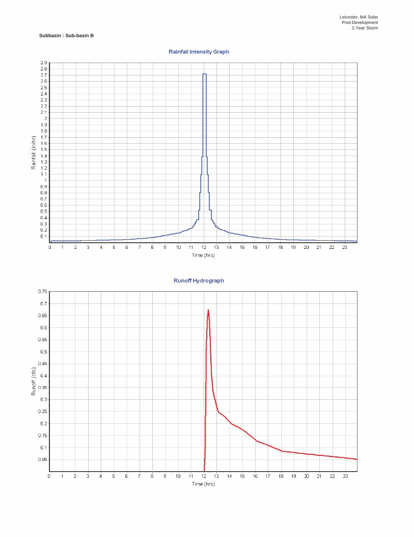
Leicester, MA SolarPost-Development
2-Year Storm
Subbasin : Sub-basin B
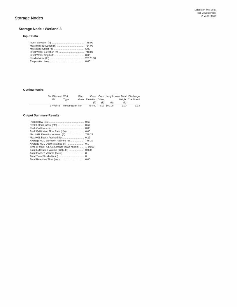
Leicester, MA SolarPost-Development
2-Year StormStorage Nodes
Storage Node : Wetland 3
Input Data
748.00754.006.00748.000.0020178.000.00
Outflow Weirs
SN Element Weir Flap Crest Crest Length Weir Total DischargeID Type Gate Elevation Offset Height Coefficient
(ft) (ft) (ft) (ft)1 Weir-B Rectangular No 754.00 6.00 100.00 1.00 3.33
Output Summary Results
0.670.670.000.00748.290.29748.100.11 00:000.000000.00
Total Time Flooded (min) ....................................Total Retention Time (sec) ..................................
Max HGL Depth Attained (ft) ...............................Average HGL Elevation Attained (ft) ....................Average HGL Depth Attained (ft) .........................Time of Max HGL Occurrence (days hh:mm) ......Total Exfiltration Volume (1000-ft³) ......................Total Flooded Volume (ac-in) ..............................
Evaporation Loss .................................................
Peak Inflow (cfs) ..................................................Peak Lateral Inflow (cfs) ......................................Peak Outflow (cfs) ...............................................Peak Exfiltration Flow Rate (cfm) ........................Max HGL Elevation Attained (ft) ..........................
Invert Elevation (ft) ...............................................Max (Rim) Elevation (ft) .......................................Max (Rim) Offset (ft) ............................................Initial Water Elevation (ft) .....................................Initial Water Depth (ft) ..........................................Ponded Area (ft²) .................................................

Leicester, MA SolarPost-Development
2-Year Storm Storage Node : Wetland 5
Input Data
784.00790.006.00784.000.0072180.000.00
Outflow Weirs
SN Element Weir Flap Crest Crest Length Weir Total DischargeID Type Gate Elevation Offset Height Coefficient
(ft) (ft) (ft) (ft)1 Weir-A Rectangular No 790.00 6.00 100.00 1.00 3.33
Output Summary Results
0.640.640.000.00784.070.07784.030.031 00:000.000000.00
Total Exfiltration Volume (1000-ft³) ......................Total Flooded Volume (ac-in) ..............................Total Time Flooded (min) ....................................Total Retention Time (sec) ..................................
Peak Exfiltration Flow Rate (cfm) ........................Max HGL Elevation Attained (ft) ..........................Max HGL Depth Attained (ft) ...............................Average HGL Elevation Attained (ft) ....................Average HGL Depth Attained (ft) .........................Time of Max HGL Occurrence (days hh:mm) ......
Initial Water Depth (ft) ..........................................Ponded Area (ft²) .................................................Evaporation Loss .................................................
Peak Inflow (cfs) ..................................................Peak Lateral Inflow (cfs) ......................................Peak Outflow (cfs) ...............................................
Invert Elevation (ft) ...............................................Max (Rim) Elevation (ft) .......................................Max (Rim) Offset (ft) ............................................Initial Water Elevation (ft) .....................................

Leicester, MA SolarPost-Development
10-Year StormProject DescriptionLeicester Stormwater Model-Post.SPF
Project OptionsCFSElevationSCS TR-55SCS TR-55Kinematic WaveYESYES
Analysis OptionsMay 22, 2017 00:00:00May 23, 2017 00:00:00May 22, 2017 00:00:000 days0 01:00:00 days hh:mm:ss0 00:05:00 days hh:mm:ss0 00:05:00 days hh:mm:ss30 seconds
Number of ElementsQty12402002200002000
Rainfall DetailsSN Rain Gage Data Data Source Rainfall Rain State County Return Rainfall Rainfall
ID Source ID Type Units Period Depth Distribution(years) (inches)
1 Leicester Time Series 10-year Cumulative inches Massachusetts Worcester 10 4.86 SCS Type III 24-hr
Land Uses ...................................................
Pipes .................................................. Pumps ................................................ Orifices ............................................... Weirs .................................................. Outlets ................................................Pollutants ....................................................
Outfalls ............................................... Flow Diversions .................................. Inlets ................................................... Storage Nodes ...................................Links............................................................. Channels ............................................
Reporting Time Step ...................................Routing Time Step ......................................
Rain Gages .................................................Subbasins....................................................Nodes........................................................... Junctions ............................................
Start Analysis On ........................................End Analysis On ..........................................Start Reporting On ......................................Antecedent Dry Days ..................................Runoff (Dry Weather) Time Step ................Runoff (Wet Weather) Time Step ...............
Elevation Type ............................................Hydrology Method .......................................Time of Concentration (TOC) Method ........Link Routing Method ...................................Enable Overflow Ponding at Nodes ............Skip Steady State Analysis Time Periods ...
File Name ....................................................Description ..................................................
Leicester, MA Solar
Stormwater Report
Flow Units ...................................................

Leicester, MA SolarPost-Development
10-Year StormSubbasin SummarySN Subbasin Area Weighted Total Total Total Peak Time of
ID Curve Rainfall Runoff Runoff Runoff ConcentrationNumber Volume
(ac) (in) (in) (ac-in) (cfs) (days hh:mm:ss)1 Sub-basin A 5.36 55.47 4.86 0.94 5.03 4.11 0 00:09:062 Sub-basin B 6.05 55.06 4.86 0.92 5.54 4.61 0 00:08:06

Leicester, MA SolarPost-Development
10-Year StormNode SummarySN Element Element Invert Ground/Rim Initial Surcharge Ponded Peak Max HGL Max Min Time of Total Total Time
ID Type Elevation (Max) Water Elevation Area Inflow Elevation Surcharge Freeboard Peak Flooded FloodedElevation Elevation Attained Depth Attained Flooding Volume
Attained Occurrence(ft) (ft) (ft) (ft) (ft²) (cfs) (ft) (ft) (ft) (days hh:mm) (ac-in) (min)
1 Out-A Outfall 761.00 0.00 761.002 Out-B Outfall 741.00 0.00 741.003 Wetland 3 Storage Node 748.00 754.00 748.00 20178.00 4.51 748.99 0.00 0.004 Wetland 5 Storage Node 784.00 790.00 784.00 72180.00 4.09 784.25 0.00 0.00

Lei
cest
er, M
A So
lar
Post
-Dev
elop
men
t10
-Yea
r Sto
rmLi
nk S
umm
ary
SNEl
emen
tEl
emen
tFr
omTo
(Out
let)
Leng
thIn
let
Out
let
Aver
age
Dia
met
er o
rM
anni
ng's
Peak
Des
ign
Flow
Peak
Flo
w/
Peak
Flo
wPe
ak F
low
Peak
Flo
wTo
tal T
ime
Rep
orte
dID
Type
(Inle
t)N
ode
Inve
rtIn
vert
Slop
eH
eigh
tR
ough
ness
Flow
Cap
acity
Des
ign
Flow
Velo
city
Dep
thD
epth
/Su
rcha
rged
Con
ditio
nN
ode
Elev
atio
nEl
evat
ion
Rat
ioTo
tal D
epth
Rat
io(ft
)(ft
)(ft
)(%
)(in
)(c
fs)
(cfs
)(ft
/sec
)(ft
)(m
in)
1W
eir-
AW
eir
Wet
land
5O
ut-A
784.
0076
1.00
0.00
2W
eir-
BW
eir
Wet
land
3O
ut-B
748.
0074
1.00
0.00

Leicester, MA SolarPost-Development
10-Year StormSubbasin Hydrology
Subbasin : Sub-basin A
Input Data
Area (ac) ........................................................................ 5.36Weighted Curve Number ............................................... 55.47Rain Gage ID ................................................................. Leicester
Composite Curve Number Area Soil CurveSoil/Surface Description (acres) Group NumberGravel roads 0.06 B 85.00Woods, Good 0.00 B 55.00Brush, Good 1.65 B 48.00Meadow, non-grazed 3.62 B 58.00Ground Screws 0.03 B 98.00Composite Area & Weighted CN 5.36 55.47
Time of Concentration
TOC Method : SCS TR-55
Sheet Flow Equation :
Tc = (0.007 * ((n * Lf)^0.8)) / ((P^0.5) * (Sf^0.4))
Where :
Tc = Time of Concentration (hr) n = Manning's roughness Lf = Flow Length (ft) P = 2 yr, 24 hr Rainfall (inches) Sf = Slope (ft/ft)
Shallow Concentrated Flow Equation :
V = 16.1345 * (Sf^0.5) (unpaved surface) V = 20.3282 * (Sf^0.5) (paved surface) V = 15.0 * (Sf^0.5) (grassed waterway surface) V = 10.0 * (Sf^0.5) (nearly bare & untilled surface) V = 9.0 * (Sf^0.5) (cultivated straight rows surface) V = 7.0 * (Sf^0.5) (short grass pasture surface) V = 5.0 * (Sf^0.5) (woodland surface) V = 2.5 * (Sf^0.5) (forest w/heavy litter surface) Tc = (Lf / V) / (3600 sec/hr)
Where:
Tc = Time of Concentration (hr) Lf = Flow Length (ft) V = Velocity (ft/sec) Sf = Slope (ft/ft)
Channel Flow Equation :
V = (1.49 * (R^(2/3)) * (Sf^0.5)) / n R = Aq / Wp Tc = (Lf / V) / (3600 sec/hr)
Where :
Tc = Time of Concentration (hr) Lf = Flow Length (ft) R = Hydraulic Radius (ft) Aq = Flow Area (ft²) Wp = Wetted Perimeter (ft) V = Velocity (ft/sec) Sf = Slope (ft/ft) n = Manning's roughness

Leicester, MA SolarPost-Development
10-Year StormSubarea Subarea Subarea
Sheet Flow Computations A B C Manning's Roughness : .4 0.00 0.00 Flow Length (ft) : 100 0.00 0.00 Slope (%) : 4 0.00 0.00 2 yr, 24 hr Rainfall (in) : 3.24 0.00 0.00 Velocity (ft/sec) : 0.10 0.00 0.00 Computed Flow Time (min) : 16.17 0.00 0.00
Subarea Subarea SubareaShallow Concentrated Flow Computations A B C Flow Length (ft) : 60 214 0.00 Slope (%) : 11 12.5 0.00 Surface Type : Woodland Grass pasture Unpaved Velocity (ft/sec) : 1.66 2.47 0.00 Computed Flow Time (min) : 0.60 1.44 0.00Total TOC (min) ..................9.11
Subbasin Runoff Results
Total Rainfall (in) ............................................................ 4.86Total Runoff (in) ............................................................. 0.94Peak Runoff (cfs) ........................................................... 4.11Weighted Curve Number ............................................... 55.47Time of Concentration (days hh:mm:ss) ........................ 0 00:09:07

Leicester, MA SolarPost-Development
10-Year Storm
Subbasin : Sub-basin A

Leicester, MA SolarPost-Development
10-Year Storm Subbasin : Sub-basin B
Input Data
Area (ac) ........................................................................ 6.05Weighted Curve Number ............................................... 55.06Rain Gage ID ................................................................. Leicester
Composite Curve Number Area Soil CurveSoil/Surface Description (acres) Group NumberGravel roads 0.35 B 85.00Woods, Good 0.00 B 55.00Brush, Good 2.73 B 48.00Meadow, non-grazed 2.97 B 58.00Ground Screws 0.00 B 98.00Composite Area & Weighted CN 6.05 55.06
Time of Concentration
Subarea Subarea SubareaSheet Flow Computations A B C Manning's Roughness : .4 0.00 0.00 Flow Length (ft) : 100 0.00 0.00 Slope (%) : 7 0.00 0.00 2 yr, 24 hr Rainfall (in) : 3.24 0.00 0.00 Velocity (ft/sec) : 0.13 0.00 0.00 Computed Flow Time (min) : 12.93 0.00 0.00
Subarea Subarea SubareaShallow Concentrated Flow Computations A B C Flow Length (ft) : 213 236 0.00 Slope (%) : 14.5 16 0.00 Surface Type : Woodland Grass pasture Unpaved Velocity (ft/sec) : 1.90 2.80 0.00 Computed Flow Time (min) : 1.87 1.40 0.00Total TOC (min) ..................8.10
Subbasin Runoff Results
Total Rainfall (in) ............................................................ 4.86Total Runoff (in) ............................................................. 0.92Peak Runoff (cfs) ........................................................... 4.61Weighted Curve Number ............................................... 55.06Time of Concentration (days hh:mm:ss) ........................ 0 00:08:06

Leicester, MA SolarPost-Development
10-Year Storm
Subbasin : Sub-basin B

Leicester, MA SolarPost-Development
10-Year StormStorage Nodes
Storage Node : Wetland 3
Input Data
748.00754.006.00748.000.0020178.000.00
Outflow Weirs
SN Element Weir Flap Crest Crest Length Weir Total DischargeID Type Gate Elevation Offset Height Coefficient
(ft) (ft) (ft) (ft)1 Weir-B Rectangular No 754.00 6.00 100.00 1.00 3.33
Output Summary Results
4.514.510.000.00748.990.99748.370.371 00:000.000000.00
Total Time Flooded (min) ....................................Total Retention Time (sec) ..................................
Max HGL Depth Attained (ft) ...............................Average HGL Elevation Attained (ft) ....................Average HGL Depth Attained (ft) .........................Time of Max HGL Occurrence (days hh:mm) ......Total Exfiltration Volume (1000-ft³) ......................Total Flooded Volume (ac-in) ..............................
Evaporation Loss .................................................
Peak Inflow (cfs) ..................................................Peak Lateral Inflow (cfs) ......................................Peak Outflow (cfs) ...............................................Peak Exfiltration Flow Rate (cfm) ........................Max HGL Elevation Attained (ft) ..........................
Invert Elevation (ft) ...............................................Max (Rim) Elevation (ft) .......................................Max (Rim) Offset (ft) ............................................Initial Water Elevation (ft) .....................................Initial Water Depth (ft) ..........................................Ponded Area (ft²) .................................................
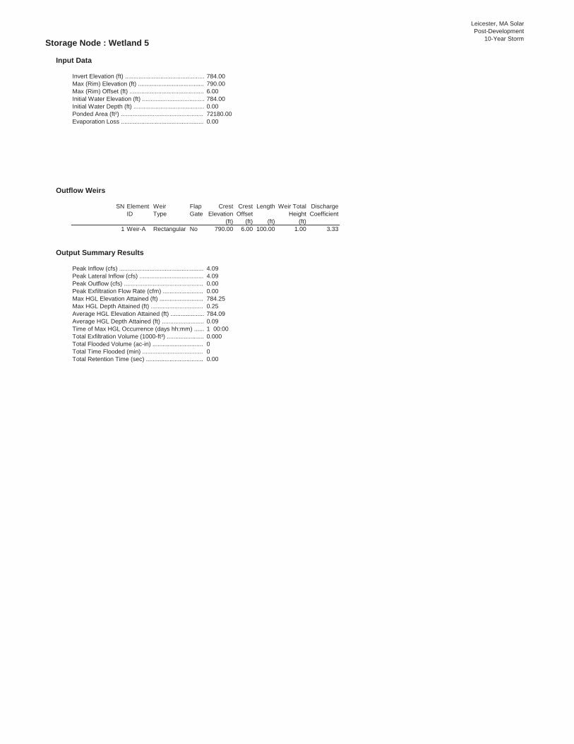
Leicester, MA SolarPost-Development
10-Year Storm Storage Node : Wetland 5
Input Data
784.00790.006.00784.000.0072180.000.00
Outflow Weirs
SN Element Weir Flap Crest Crest Length Weir Total DischargeID Type Gate Elevation Offset Height Coefficient
(ft) (ft) (ft) (ft)1 Weir-A Rectangular No 790.00 6.00 100.00 1.00 3.33
Output Summary Results
4.094.090.000.00784.250.25784.090.091 00:000.000000.00
Total Exfiltration Volume (1000-ft³) ......................Total Flooded Volume (ac-in) ..............................Total Time Flooded (min) ....................................Total Retention Time (sec) ..................................
Peak Exfiltration Flow Rate (cfm) ........................Max HGL Elevation Attained (ft) ..........................Max HGL Depth Attained (ft) ...............................Average HGL Elevation Attained (ft) ....................Average HGL Depth Attained (ft) .........................Time of Max HGL Occurrence (days hh:mm) ......
Initial Water Depth (ft) ..........................................Ponded Area (ft²) .................................................Evaporation Loss .................................................
Peak Inflow (cfs) ..................................................Peak Lateral Inflow (cfs) ......................................Peak Outflow (cfs) ...............................................
Invert Elevation (ft) ...............................................Max (Rim) Elevation (ft) .......................................Max (Rim) Offset (ft) ............................................Initial Water Elevation (ft) .....................................


42° 1
4' 1
5'' N
71° 52' 54'' W42
° 1
4' 1
5'' N
71° 51' 21'' W
42° 1
3' 3
0'' N
71° 52' 54'' W
42° 1
3' 3
0'' N
71° 51' 21'' W
N
Map
pro
ject
ion:
Web
Mer
cato
r C
orne
r coo
rdin
ates
: WGS
84
Edge
tics
: UTM
Zon
e 19
N W
GS84
Feet
Met
ers
Map
Sca
le: 1
:9,6
80 if p
rinte
d on
A la
ndsc
ape
(11"
x 8
.5")
shee
t.
Soi
l Map
may
not
be
valid
at
this
sca
le.


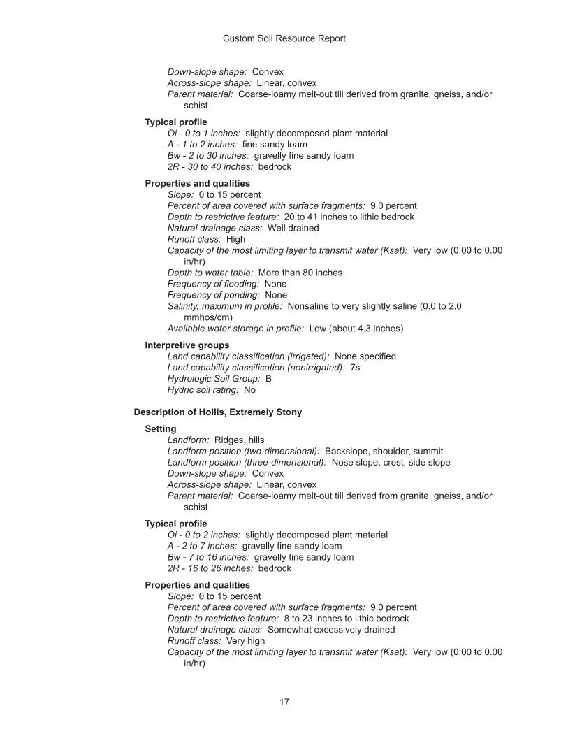


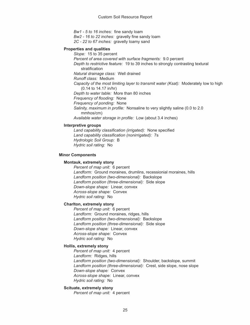


Attachment G
Abutters List