wr250rb - scf99fe700a0cb239.jimcontent.com · this motorcycle is designed to car-ry the operator...
TRANSCRIPT

q Read this manual carefully before operating this vehicle.
OWNER’S MANUAL
WR250RB32D-28199-28
Q Read this manual carefully before operating this vehicle. This manual should stay with this vehicle if it is sold.
EAU46090
INTRODUCTIONEAU10102
Welcome to the Yamaha world of motorcycling!As the owner of the WR250RB, you are benefiting from Yamaha’s vast experience and newest technology regarding thedesign and manufacture of high-quality products, which have earned Yamaha a reputation for dependability.Please take the time to read this manual thoroughly, so as to enjoy all advantages of your WR250RB. The Owner’s Manualdoes not only instruct you in how to operate, inspect and maintain your motorcycle, but also in how to safeguard yourself andothers from trouble and injury.In addition, the many tips given in this manual will help keep your motorcycle in the best possible condition. If you have anyfurther questions, do not hesitate to contact your Yamaha dealer.The Yamaha team wishes you many safe and pleasant rides. So, remember to put safety first!Yamaha continually seeks advancements in product design and quality. Therefore, while this manual contains the most cur-rent product information available at the time of printing, there may be minor discrepancies between your motorcycle and thismanual. If there is any question concerning this manual, please consult a Yamaha dealer.
WARNINGEWA10031
Please read this manual carefully and completely before operating this motorcycle.
32D-9-28-E0.book 1 ページ 2011年6月29日 水曜日 午後5時28分
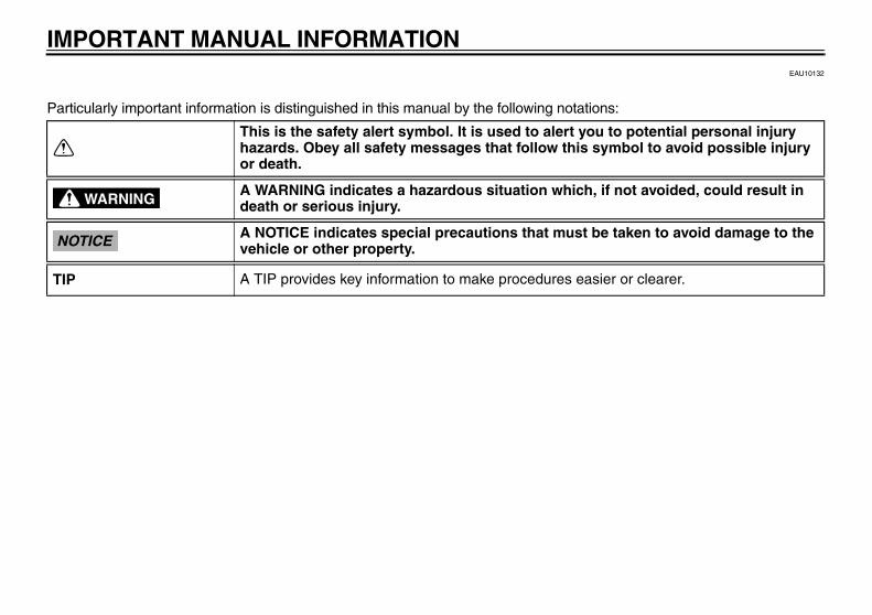
IMPORTANT MANUAL INFORMATIONEAU10132
Particularly important information is distinguished in this manual by the following notations:
This is the safety alert symbol. It is used to alert you to potential personal injury hazards. Obey all safety messages that follow this symbol to avoid possible injury or death.
A WARNING indicates a hazardous situation which, if not avoided, could result in death or serious injury.
A NOTICE indicates special precautions that must be taken to avoid damage to the vehicle or other property.
A TIP provides key information to make procedures easier or clearer.
WARNING
NOTICE
TIP
32D-9-28-E0.book 1 ページ 2011年6月29日 水曜日 午後5時28分
IMPORTANT MANUAL INFORMATION
EAU10200
WR250RBOWNER’S MANUAL
©2011 by Yamaha Motor Co., Ltd.1st edition, June 2011
All rights reserved.Any reprinting or unauthorized use without the written permission of
Yamaha Motor Co., Ltd. is expressly prohibited.
Printed in Japan.
32D-9-28-E0.book 2 ページ 2011年6月29日 水曜日 午後5時28分

TABLE OF CONTENTSLOCATION OF IMPORTANT LABELS ............................................. 1-1
SAFETY INFORMATION .................. 2-1
DESCRIPTION .................................. 3-1Left view .......................................... 3-1Right view ........................................ 3-2Controls and instruments................. 3-3
INSTRUMENT AND CONTROL FUNCTIONS ....................................... 4-1
Main switch/steering lock ................ 4-1Indicator lights and warning
lights ............................................ 4-2Multi-function display ...................... 4-3Handlebar switches ........................ 4-8Clutch lever ..................................... 4-9Shift pedal ..................................... 4-10Brake lever ................................... 4-10Brake pedal .................................. 4-10Fuel tank cap ................................ 4-11Fuel ............................................... 4-11Catalytic converter ........................ 4-13Seat .............................................. 4-13Helmet holder ............................... 4-14Adjusting the front fork .................. 4-14Front fork bleeding ........................ 4-16Adjusting the shock absorber
assembly ................................... 4-17EXUP system ............................... 4-18
Sidestand ..................................... 4-19Ignition circuit cut-off system ........ 4-19
FOR YOUR SAFETY – PRE-OPERATION CHECKS ............. 5-1
OPERATION AND IMPORTANT RIDING POINTS................................. 6-1
Starting the engine ......................... 6-1Shifting ........................................... 6-2Tips for reducing fuel
consumption ............................... 6-3Engine break-in .............................. 6-3Parking ........................................... 6-4
PERIODIC MAINTENANCE AND ADJUSTMENT ................................... 7-1
Owner’s tool kit ............................... 7-2Periodic maintenance chart for
the emission control system ....... 7-3General maintenance and
lubrication chart .......................... 7-4Removing and installing panels ..... 7-8Checking the spark plug ............... 7-11Engine oil and oil filter element .... 7-12Coolant ......................................... 7-14Cleaning the air filter element
and check hose ......................... 7-17Adjusting the engine idling
speed ........................................ 7-19
Checking the throttle grip free play ............................................ 7-19
Valve clearance ............................ 7-20Tires .............................................. 7-20Spoke wheels ............................... 7-22Adjusting the clutch lever free
play ............................................ 7-22Adjusting the brake lever free
play ............................................ 7-23Checking the shift pedal ............... 7-24Brake light switches ...................... 7-24Checking the front and rear
brake pads ................................. 7-25Checking the brake fluid level ....... 7-25Changing the brake fluid ............... 7-26Drive chain slack ........................... 7-27Cleaning and lubricating the
drive chain ................................. 7-28Checking and lubricating the
cables ........................................ 7-29Checking and lubricating the
throttle grip and cable ................ 7-29Checking and lubricating the
brake and clutch levers ............. 7-29Checking and lubricating the
brake pedal ................................ 7-30Checking and lubricating the
sidestand ................................... 7-30Lubricating the swingarm pivots ... 7-31Checking the front fork .................. 7-31Checking the steering ................... 7-32
32D-9-28-E0.book 1 ページ 2011年6月29日 水曜日 午後5時28分

TABLE OF CONTENTSChecking the wheel bearings ....... 7-32Battery .......................................... 7-32Replacing the fuses ...................... 7-34Replacing the headlight bulb ........ 7-35Tail/brake light .............................. 7-36Replacing a turn signal light
bulb ........................................... 7-36Replacing the license plate
light bulb .................................... 7-37Replacing an auxiliary light
bulb ........................................... 7-38Supporting the motorcycle ............ 7-38Front wheel ................................... 7-39Rear wheel ................................... 7-40Troubleshooting ............................ 7-41Troubleshooting charts ................. 7-43
MOTORCYCLE CARE AND STORAGE .......................................... 8-1
Matte color caution ......................... 8-1Care ................................................ 8-1Storage ........................................... 8-3
SPECIFICATIONS ............................. 9-1
CONSUMER INFORMATION........... 10-1Identification numbers .................. 10-1Motorcycle noise regulation
(for Australia) ............................ 10-2
32D-9-28-E0.book 2 ページ 2011年6月29日 水曜日 午後5時28分

1-1
1
LOCATION OF IMPORTANT LABELS EAU10384
Read and understand all of the labels on your vehicle. They contain important information for safe and proper operation ofyour vehicle. Never remove any labels from your vehicle. If a label becomes difficult to read or comes off, a replacement labelis available from your Yamaha dealer.
21 43
32D-9-28-E0.book 1 ページ 2011年6月29日 水曜日 午後5時28分

LOCATION OF IMPORTANT LABELS
1-2
1
2
3
4
5
6
7
8
9
4AA-22259-40
Cold tire normal pressure should be setas follows.
Up to 90 kg (198 lbs) load: 125 },kPa, {1.25 kgf/cm2 18 psi: 175 kPa, {1.75 kgf/cm2}, 25 psi
90 kg (198 lbs): 150 },kPa, {1.50 kgf/cm2 22 psi: 200 kPa, {2.00 kgf/cm2}, 29 psi
~maximum load
32C-21668-00
Use PREMIUM unleaded gasoline withmin. 95 octane(RON).
2S3-2817K-00
WARNINGBEFORE YOU OPERATE THIS VEHICLE, READTHE OWNER’S MANUAL AND ALL LABELS.ALWAYS WEAR AN APPROVED MOTORCYCLEHELMET, eye protection, and protective clothing.
5GK-2118K-00
1
2
3
4
32D-9-28-E0.book 2 ページ 2011年6月29日 水曜日 午後5時28分

LOCATION OF IMPORTANT LABELS
1-3
1
1 2
32D-9-28-E0.book 3 ページ 2011年6月29日 水曜日 午後5時28分

LOCATION OF IMPORTANT LABELS
1-4
1
2
3
4
5
6
7
8
9
STATIONARY NOISE TEST INFORMATIONTESTED 88 dB(A) AT 5000 r/minSILENCING SYSTEM : YAMAHAIDENTIFICATION : 32D
32D-2118G-20
1
2
32D-9-28-E0.book 4 ページ 2011年6月29日 水曜日 午後5時28分

2-1
1
2
SAFETY INFORMATION EAU1031A
Be a Responsible OwnerAs the vehicle’s owner, you are respon-sible for the safe and proper operationof your motorcycle.Motorcycles are single-track vehicles.Their safe use and operation are de-pendent upon the use of proper ridingtechniques as well as the expertise ofthe operator. Every operator shouldknow the following requirements beforeriding this motorcycle.He or she should: Obtain thorough instructions from
a competent source on all aspectsof motorcycle operation.
Observe the warnings and mainte-nance requirements in this Own-er’s Manual.
Obtain qualified training in safeand proper riding techniques.
Obtain professional technical ser-vice as indicated in this Owner’sManual and/or when made neces-sary by mechanical conditions.
Safe RidingPerform the pre-operation checks eachtime you use the vehicle to make sure itis in safe operating condition. Failure toinspect or maintain the vehicle properlyincreases the possibility of an accidentor equipment damage. See page 5-1for a list of pre-operation checks. This motorcycle is designed to car-
ry the operator and a passenger. The failure of motorists to detect
and recognize motorcycles in traf-fic is the predominating cause ofautomobile/motorcycle accidents.Many accidents have been causedby an automobile driver who didnot see the motorcycle. Makingyourself conspicuous appears tobe very effective in reducing thechance of this type of accident.Therefore:• Wear a brightly colored jacket.• Use extra caution when you are
approaching and passingthrough intersections, since in-tersections are the most likelyplaces for motorcycle accidentsto occur.
• Ride where other motorists can
see you. Avoid riding in anothermotorist’s blind spot.
Many accidents involve inexperi-enced operators. In fact, many op-erators who have been involved inaccidents do not even have a cur-rent motorcycle license.• Make sure that you are qualified
and that you only lend your mo-torcycle to other qualified opera-tors.
• Know your skills and limits.Staying within your limits mayhelp you to avoid an accident.
• We recommend that you prac-tice riding your motorcyclewhere there is no traffic until youhave become thoroughly famil-iar with the motorcycle and all ofits controls.
Many accidents have been causedby error of the motorcycle opera-tor. A typical error made by the op-erator is veering wide on a turndue to excessive speed or under-cornering (insufficient lean anglefor the speed).• Always obey the speed limit and
never travel faster than warrant-
32D-9-28-E0.book 1 ページ 2011年6月29日 水曜日 午後5時28分

SAFETY INFORMATION
2-2
2
3
4
5
6
7
8
9
ed by road and traffic conditions.• Always signal before turning or
changing lanes. Make sure thatother motorists can see you.
The posture of the operator andpassenger is important for propercontrol.• The operator should keep both
hands on the handlebar andboth feet on the operator foot-rests during operation to main-tain control of the motorcycle.
• The passenger should alwayshold onto the operator, the seatstrap or grab bar, if equipped,with both hands and keep bothfeet on the passenger footrests.Never carry a passenger unlesshe or she can firmly place bothfeet on the passenger footrests.
Never ride under the influence ofalcohol or other drugs.
Protective ApparelThe majority of fatalities from motorcy-cle accidents are the result of head in-juries. The use of a safety helmet is thesingle most critical factor in the preven-tion or reduction of head injuries.
Always wear an approved helmet. Wear a face shield or goggles.
Wind in your unprotected eyescould contribute to an impairmentof vision that could delay seeing ahazard.
The use of a jacket, heavy boots,trousers, gloves, etc., is effective inpreventing or reducing abrasionsor lacerations.
Never wear loose-fitting clothes,otherwise they could catch on thecontrol levers, footrests, or wheelsand cause injury or an accident.
Always wear protective clothingthat covers your legs, ankles, andfeet. The engine or exhaust sys-tem become very hot during or af-ter operation and can cause burns.
A passenger should also observethe above precautions.
Avoid Carbon Monoxide PoisoningAll engine exhaust contains carbonmonoxide, a deadly gas. Breathing car-bon monoxide can cause headaches,dizziness, drowsiness, nausea, confu-sion, and eventually death.Carbon Monoxide is a colorless, odor-
less, tasteless gas which may bepresent even if you do not see or smellany engine exhaust. Deadly levels ofcarbon monoxide can collect rapidlyand you can quickly be overcome andunable to save yourself. Also, deadlylevels of carbon monoxide can lingerfor hours or days in enclosed or poorlyventilated areas. If you experience anysymptoms of carbon monoxide poison-ing, leave the area immediately, getfresh air, and SEEK MEDICAL TREAT-MENT. Do not run engine indoors. Even if
you try to ventilate engine exhaustwith fans or open windows anddoors, carbon monoxide can rap-idly reach dangerous levels.
Do not run engine in poorly venti-lated or partially enclosed areassuch as barns, garages, or car-ports.
Do not run engine outdoors whereengine exhaust can be drawn intoa building through openings suchas windows and doors.
LoadingAdding accessories or cargo to your
32D-9-28-E0.book 2 ページ 2011年6月29日 水曜日 午後5時28分

2-3
1
2
3
4
5
6
7
8
9
SAFETY INFORMATIONmotorcycle can adversely affect stabili-ty and handling if the weight distributionof the motorcycle is changed. To avoidthe possibility of an accident, use ex-treme caution when adding cargo oraccessories to your motorcycle. Useextra care when riding a motorcyclethat has added cargo or accessories.Here, along with the information aboutaccessories below, are some generalguidelines to follow if loading cargo toyour motorcycle:The total weight of the operator, pas-senger, accessories and cargo mustnot exceed the maximum load limit.Operation of an overloaded vehiclecould cause an accident.
When loading within this weight limit,keep the following in mind: Cargo and accessory weight
should be kept as low and close tothe motorcycle as possible. Se-curely pack your heaviest items asclose to the center of the vehicle aspossible and make sure to distrib-
ute the weight as evenly as possi-ble on both sides of the motorcycleto minimize imbalance or instabili-ty.
Shifting weights can create a sud-den imbalance. Make sure that ac-cessories and cargo are securelyattached to the motorcycle beforeriding. Check accessory mountsand cargo restraints frequently.• Properly adjust the suspension
for your load (suspension-ad-justable models only), andcheck the condition and pres-sure of your tires.
• Never attach any large or heavyitems to the handlebar, frontfork, or front fender. Theseitems, including such cargo assleeping bags, duffel bags, ortents, can create unstable han-dling or a slow steering re-sponse.
This vehicle is not designed topull a trailer or to be attached toa sidecar.
Genuine Yamaha AccessoriesChoosing accessories for your vehicle
is an important decision. GenuineYamaha accessories, which are avail-able only from a Yamaha dealer, havebeen designed, tested, and approvedby Yamaha for use on your vehicle.Many companies with no connection toYamaha manufacture parts and acces-sories or offer other modifications forYamaha vehicles. Yamaha is not in aposition to test the products that theseaftermarket companies produce.Therefore, Yamaha can neither en-dorse nor recommend the use of ac-cessories not sold by Yamaha ormodifications not specifically recom-mended by Yamaha, even if sold andinstalled by a Yamaha dealer.
Aftermarket Parts, Accessories, and ModificationsWhile you may find aftermarket prod-ucts similar in design and quality togenuine Yamaha accessories, recog-nize that some aftermarket accessoriesor modifications are not suitable be-cause of potential safety hazards to youor others. Installing aftermarket prod-ucts or having other modifications per-formed to your vehicle that change any
Maximum load: 185 kg (408 lb)
32D-9-28-E0.book 3 ページ 2011年6月29日 水曜日 午後5時28分

SAFETY INFORMATION
2-4
2
3
4
5
6
7
8
9
of the vehicle’s design or operationcharacteristics can put you and othersat greater risk of serious injury or death.You are responsible for injuries relatedto changes in the vehicle.Keep the following guidelines in mind,as well as those provided under “Load-ing” when mounting accessories. Never install accessories or carry
cargo that would impair the perfor-mance of your motorcycle. Care-fully inspect the accessory beforeusing it to make sure that it doesnot in any way reduce groundclearance or cornering clearance,limit suspension travel, steeringtravel or control operation, or ob-scure lights or reflectors.• Accessories fitted to the handle-
bar or the front fork area cancreate instability due to improperweight distribution or aerody-namic changes. If accessoriesare added to the handlebar orfront fork area, they must be aslightweight as possible andshould be kept to a minimum.
• Bulky or large accessories mayseriously affect the stability of
the motorcycle due to aerody-namic effects. Wind may at-tempt to lift the motorcycle, orthe motorcycle may become un-stable in cross winds. These ac-cessories may also causeinstability when passing or beingpassed by large vehicles.
• Certain accessories can dis-place the operator from his orher normal riding position. Thisimproper position limits the free-dom of movement of the opera-tor and may limit control ability,therefore, such accessories arenot recommended.
Use caution when adding electri-cal accessories. If electrical acces-sories exceed the capacity of themotorcycle’s electrical system, anelectric failure could result, whichcould cause a dangerous loss oflights or engine power.
Aftermarket Tires and RimsThe tires and rims that came with yourmotorcycle were designed to match theperformance capabilities and to providethe best combination of handling, brak-
ing, and comfort. Other tires, rims, siz-es, and combinations may not beappropriate. Refer to page 7-20 for tirespecifications and more information onreplacing your tires.
Transporting the MotorcycleBe sure to observe following instruc-tions before transporting the motorcy-cle in another vehicle. Remove all loose items from the
motorcycle. Check that the fuel cock (if
equipped) is in the “OFF” positionand that there are no fuel leaks.
Point the front wheel straightahead on the trailer or in the truckbed, and choke it in a rail to pre-vent movement.
Shift the transmission in gear (formodels with a manual transmis-sion).
Secure the motorcycle withtie-downs or suitable straps thatare attached to solid parts of themotorcycle, such as the frame orupper front fork triple clamp (andnot, for example, to rubber-mount-ed handlebars or turn signals, or
32D-9-28-E0.book 4 ページ 2011年6月29日 水曜日 午後5時28分
2-5
1
2
3
4
5
6
7
8
9
SAFETY INFORMATIONparts that could break). Choosethe location for the straps carefullyso the straps will not rub againstpainted surfaces during transport.
The suspension should be com-pressed somewhat by thetie-downs, if possible, so that themotorcycle will not bounce exces-sively during transport.
32D-9-28-E0.book 5 ページ 2011年6月29日 水曜日 午後5時28分

3-1
2
3
4
5
6
7
8
9
DESCRIPTIONEAU10410
Left view
4 51 2, 3 6 7 8
91. Front fork rebound damping force adjusting screw (page 4-14)
2. Fuse box (page 7-34)
3. Coolant reservoir (page 7-14)
4. Shock absorber assembly compression damping force adjusting screw (page 4-17)
5. Battery (page 7-32)
6. Main fuse (page 7-34)
7. Owner’s tool kit (page 7-2)
8. Helmet holder (page 4-14)
9. Front fork compression damping force adjusting screw (page 4-14)
32D-9-28-E0.book 1 ページ 2011年6月29日 水曜日 午後5時28分
DESCRIPTION
3-2
1
2
3
4
5
6
7
8
9
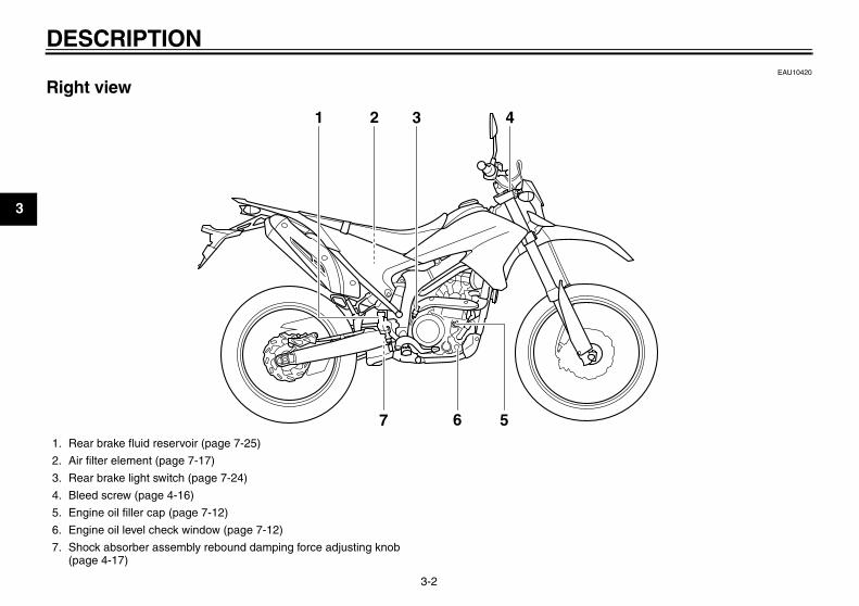
EAU10420
Right view
31 2
7 6 5
4
1. Rear brake fluid reservoir (page 7-25)
2. Air filter element (page 7-17)
3. Rear brake light switch (page 7-24)
4. Bleed screw (page 4-16)
5. Engine oil filler cap (page 7-12)
6. Engine oil level check window (page 7-12)
7. Shock absorber assembly rebound damping force adjusting knob (page 4-17)
32D-9-28-E0.book 2 ページ 2011年6月29日 水曜日 午後5時28分

DESCRIPTION
3-3
2
3
4
5
6
7
8
9
EAU10430
Controls and instruments
1 2 3 4 5 6
8
7
1. Clutch lever (page 4-9)
2. Left handlebar switches (page 4-8)
3. Main switch/steering lock (page 4-1)
4. Multi-function display (page 4-3)
5. Right handlebar switches (page 4-8)
6. Brake lever (page 4-10)
7. Throttle grip (page 7-19)
8. Fuel tank cap (page 4-11)
32D-9-28-E0.book 3 ページ 2011年6月29日 水曜日 午後5時28分
4-1
1
2
3
4
5
6
7
8
9
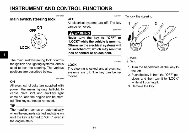
INSTRUMENT AND CONTROL FUNCTIONSEAU10460
Main switch/steering lock
The main switch/steering lock controlsthe ignition and lighting systems, and isused to lock the steering. The variouspositions are described below.
EAU38530
ONAll electrical circuits are supplied withpower; the meter lighting, taillight, li-cense plate light and auxiliary lightcome on, and the engine can be start-ed. The key cannot be removed.
TIPThe headlight comes on automaticallywhen the engine is started and stays onuntil the key is turned to “OFF”, even ifthe engine stalls.
EAU10661
OFFAll electrical systems are off. The keycan be removed.
WARNINGEWA10061
Never turn the key to “OFF” or“LOCK” while the vehicle is moving.Otherwise the electrical systems willbe switched off, which may result inloss of control or an accident.
EAU10683
LOCKThe steering is locked, and all electricalsystems are off. The key can be re-moved.
To lock the steering
1. Turn the handlebars all the way tothe left.
2. Push the key in from the “OFF” po-sition, and then turn it to “LOCK”while still pushing it.
3. Remove the key.
1. Push.
2. Turn.
1 2
32D-9-28-E0.book 1 ページ 2011年6月29日 水曜日 午後5時28分

INSTRUMENT AND CONTROL FUNCTIONS
4-2
2
3
4
5
6
7
8
9
To unlock the steering
Push the key in, and then turn it to“OFF” while still pushing it.
EAU49391
Indicator lights and warning lights
EAU11020
Turn signal indicator light “ ” This indicator light flashes when theturn signal switch is pushed to the left orright.
EAU11060
Neutral indicator light “ ” This indicator light comes on when thetransmission is in the neutral position.
EAU11080
High beam indicator light “ ” This indicator light comes on when thehigh beam of the headlight is switchedon.
EAU11352
Fuel level warning light “ ” This warning light comes on when thefuel level drops below approximately2.1 L (0.55 US gal, 0.46 Imp.gal). Whenthis occurs, refuel as soon as possible.The electrical circuit of the warning lightcan be checked by turning the key to“ON”. The warning light should comeon for a few seconds, and then go off.If the warning light does not come oninitially when the key is turned to “ON”,or if the warning light remains on, havea Yamaha dealer check the electricalcircuit.
EAU11446
Coolant temperature warning light “ ” This warning light comes on if the en-gine overheats. If this occurs, stop theengine immediately and allow the en-gine to cool.The electrical circuit of the warning light
1. Push.
2. Turn.
1 2
1. Coolant temperature warning light “ ”
2. Fuel level warning light “ ”
3. Neutral indicator light “ ”
4. Turn signal indicator light “ ”
5. High beam indicator light “ ”
6. Engine trouble warning light “ ”
1 2 3 4
56
32D-9-28-E0.book 2 ページ 2011年6月29日 水曜日 午後5時28分

INSTRUMENT AND CONTROL FUNCTIONS
4-3
1
2
3
4
5
6
7
8
9
can be checked by turning the key to“ON”. The warning light should comeon for a few seconds, and then go off.If the warning light does not come oninitially when the key is turned to “ON”,or if the warning light remains on, havea Yamaha dealer check the electricalcircuit.
NOTICEECA10021
Do not continue to operate the en-gine if it is overheating.
TIP For radiator-fan-equipped vehi-
cles, the radiator fan(s) automati-cally switch on or off according tothe coolant temperature in the ra-diator.
If the engine overheats, see page7-44 for further instructions.
EAU11534
Engine trouble warning light “ ” This warning light comes on or flashesif a problem is detected in the electricalcircuit monitoring the engine. If this oc-curs, have a Yamaha dealer check theself-diagnosis system. (See page 4-8
for an explanation of the self-diagnosisdevice.)The electrical circuit of the warning lightcan be checked by turning the key to“ON”. The warning light should comeon for a few seconds, and then go off.If the warning light does not come oninitially when the key is turned to “ON”,or if the warning light remains on, havea Yamaha dealer check the electricalcircuit.
EAU45286
Multi-function display
WARNINGEWA12312
Be sure to stop the vehicle beforemaking any setting changes to themulti-function display. Changingsettings while riding can distract theoperator and increase the risk of anaccident.
1. “RESET” button
2. “SELECT 1” button
3. “SELECT 2” button
4. Clock/stopwatch
5. Speedometer
6. Odometer/tripmeter/fuel reserve tripmeter
1 2 3 4
56
32D-9-28-E0.book 3 ページ 2011年6月29日 水曜日 午後5時28分

INSTRUMENT AND CONTROL FUNCTIONS
4-4
2
3
4
5
6
7
8
9
TIP The multi-function display can be
set to the basic mode or the mea-surement mode.
Tripmeter A will automatically re-set to zero when changing fromthe basic mode to the measure-ment mode or vice versa.
Basic mode: a speedometer an odometer two tripmeters (which show the
distance traveled since they were
last set to zero) a fuel reserve tripmeter (which
shows the distance traveled sincethe fuel level warning light cameon)
a clock a self-diagnosis device
Measurement mode: a speedometer a distance-compensation tripme-
ter (which shows the accumulateddistance traveled since set to zeroand which can be calibrated to pro-vide a more accurate tripmeterreading)
a stopwatch (which shows the timethat has been accumulated sincethe start of stopwatch measure-ment)
a self-diagnosis device
TIP Be sure to turn the key to “ON” be-
fore using the “SELECT 1”, “SE-LECT 2” and “RESET” buttons.
When the key is turned to “ON”, allof the display segments of themulti-function display will appear
and then disappear, in order to testthe electrical circuit.
Basic mode
Odometer and tripmeter modesPush the “SELECT 2” button to switchthe display between the odometermode and the tripmeter modes A and Bin the following order:odometer tripmeter A tripmeter B odometer
1. Stopwatch indicator “ ”
2. Tripmeter A indicator “ ”/Distance-com-pensation tripmeter “ ”
3. Tripmeter B indicator “ ”
1
3
2
1. Tripmeter A indicator “ ”
1
32D-9-28-E0.book 4 ページ 2011年6月29日 水曜日 午後5時28分

INSTRUMENT AND CONTROL FUNCTIONS
4-5
1
2
3
4
5
6
7
8
9
TIPIndicator “ ” comes on when tripmeterA is selected, and indicator “ ” comeson when tripmeter B is selected.
If the fuel level warning light comes on(see page 4-2), the display will auto-matically change to the fuel reservetripmeter mode “F” and start countingthe distance traveled from that point. Inthis case, push the “SELECT 2” buttonto switch the display between the vari-ous tripmeter and odometer modes inthe following order:fuel reserve tripmeter “F” odometer tripmeter A tripmeter B fuel re-serve tripmeter “F”
TIPThe fuel level warning light may notfunction accurately while riding off roadas the fuel level reading changes due tothe movement and inclination of the ve-hicle.
If the fuel level warning light comes onwhile riding in the measurement mode,change to the basic mode and push the“SELECT 2” button to display the fuelreserve tripmeter.
TIPTo change from the measurementmode to the basic mode, the stopwatchand the distance-compensation tripme-ter must be stopped.
To reset a tripmeter, select it by push-ing the “SELECT 2” button, and thenpush the “RESET” button for at leastone second. If you do not reset the fuelreserve tripmeter manually, it will resetitself automatically and the display willreturn to the prior mode after refuelingand traveling 5 km (3 mi).
ClockThe clock displays when the key isturned to “ON”.
To set the clock1. Push the “SELECT 1” button for at
least two seconds.2. When the hour digits start flashing,
push either select button to set thehours.
3. Push the “RESET” button, and theminute digits will start flashing.
4. Push either select button to set theminutes.
5. Push the “RESET” button, and thesecond digits will start flashing.
6. Push either select button to set thesecond digits to zero.
7. Push the “RESET” button for atleast two seconds, and then re-
1. Tripmeter B indicator “ ”
1
1. Fuel reserve tripmeter “F”
1
32D-9-28-E0.book 5 ページ 2011年6月29日 水曜日 午後5時28分

INSTRUMENT AND CONTROL FUNCTIONS
4-6
2
3
4
5
6
7
8
9
lease it to start the clock.
TIP When setting the clock, push the
“SELECT 1” button to increase thedigits or “SELECT 2” button to de-crease the digits. Pushing andholding either button will increaseor decrease the digits continuouslyuntil the button is released.
If the “RESET” button is notpushed within 30 seconds, theclock will not be set and will returnto the prior time.
Changing from the basic mode to the measurement modeWith the odometer selected, push the“SELECT 1” button and “SELECT 2”button together for at least two secondsto change to the measurement mode.
Changing from the measurement mode to the basic mode
TIPThe stopwatch must be stopped beforechanging to the basic mode.
1. Check that the stopwatch is not in
operation. If the stopwatch is in op-eration, stop it by pushing the “SE-LECT 1” button and “SELECT 2”button together.
2. Push the “SELECT 1” button and“SELECT 2” button together for atleast two seconds to change to thebasic mode.
Measurement mode (for the stop-watch)When the measurement mode is se-lected, the stopwatch is displayed and itcan be started manually or automatical-ly.
Manual startThe manual start is the default settingfor the stopwatch. The stopwatch indi-cator “ ” and the distance-compensa-tion tripmeter indicator “ ” will startflashing.
1. Push the “RESET” button to startthe stopwatch.
2. Push the “SELECT 1” button and“SELECT 2” button together tostop the stopwatch.
3. To resume stopwatch counting,push the “SELECT 1” button and“SELECT 2” button together.To reset the stopwatch to zero,push the “RESET” button for atleast two seconds.
TIPThe stopwatch will continue countingwhen the vehicle is stopped. To stopand/or resume counting, repeat steps 2and 3.
32D-9-28-E0.book 6 ページ 2011年6月29日 水曜日 午後5時28分

INSTRUMENT AND CONTROL FUNCTIONS
4-7
1
2
3
4
5
6
7
8
9
Auto start1. Push the “SELECT 1” button for at
least two seconds to set the autostart.
TIPWhen the stopwatch is set to auto start,the stopwatch indicator “ ” and thedistance-compensation tripmeter indi-cator “ ” will start flashing, and the dig-its in the display will start scrolling fromleft to right.
2. When the vehicle starts moving,the stopwatch will start counting.
3. Push the “SELECT 1” button and“SELECT 2” button together tostop the stopwatch.
4. To resume counting, push the “SE-LECT 1” button and “SELECT 2”
button together again.
TIPThe stopwatch will continue countingwhen the vehicle is stopped. To stopand/or resume counting, repeat steps 3and 4.
Measurement mode (for calibrating the distance-compensation tripme-ter’s reading)The distance-compensation tripmeteris a feature intended to provide a moreaccurate tripmeter reading for enduroriding. Calibrating this meter in accor-dance with the distances specified onthe enduro course map will help famil-iarize the rider with the course. In addi-tion, calibrating the meter may also benecessary when using tire, wheel,chain sprocket sizes, etc. other thanspecified. For further information con-cerning the use of this meter, pleaseconsult your nearby Yamaha dealer.Calibrate the distance-compensationtripmeter as follows.To increase the reading, push the “SE-LECT 1” button. To decrease the read-ing, push the “SELECT 2” button.
Pushing and holding either button willincrease or decrease the reading con-tinuously until the button is released.
TIPCalibrating the reading of the dis-tance-compensation tripmeter is possi-ble regardless of the stopwatchoperation.
Resetting the distance-compensa-tion tripmeter or the distance-com-pensation tripmeter in combination with the stopwatch
TIPResetting can be made only to the dis-tance-compensation tripmeter or to thedistance-compensation tripmeter incombination with the stopwatch.
Resetting the distance-compensationtripmeter
1. Check that the stopwatch mea-surement is in operation.
2. Reset the distance-compensationtripmeter to zero by pushing the“RESET” button for at least twoseconds.
32D-9-28-E0.book 7 ページ 2011年6月29日 水曜日 午後5時28分

INSTRUMENT AND CONTROL FUNCTIONS
4-8
2
3
4
5
6
7
8
9
Resetting the distance-compensationtripmeter in combination with the stop-watch
1. Stop the stopwatch.2. Reset the distance-compensation
tripmeter and the stopwatch tozero by pushing the “RESET” but-ton for at least two seconds.
Self-diagnosis deviceThis model is equipped with a self-diag-nosis device for various electrical cir-cuits.If a problem is detected in any of thosecircuits, the engine trouble warning lightwill come on and the display will indi-cate an error code.If the display indicates any error codes,note the code number, and then have aYamaha dealer check the vehicle.
NOTICEECA11590
If the display indicates an errorcode, the vehicle should be checkedas soon as possible in order to avoidengine damage.
EAU12349
Handlebar switches
Left
Right
1. Error code display
1
1. Dimmer switch “ / ”
2. Turn signal switch “ / ”
3. Horn switch “ ”
1. Engine stop switch “ / ”
2. Start switch “ ”
1
23
1
2
32D-9-28-E0.book 8 ページ 2011年6月29日 水曜日 午後5時28分

INSTRUMENT AND CONTROL FUNCTIONS
4-9
1
2
3
4
5
6
7
8
9
EAU12400
Dimmer switch “ / ” Set this switch to “ ” for the highbeam and to “ ” for the low beam.
EAU12460
Turn signal switch “ / ” To signal a right-hand turn, push thisswitch to “ ”. To signal a left-handturn, push this switch to “ ”. When re-leased, the switch returns to the centerposition. To cancel the turn signallights, push the switch in after it has re-turned to the center position.
EAU12500
Horn switch “ ” Press this switch to sound the horn.
EAU12660
Engine stop switch “ / ” Set this switch to “ ” before startingthe engine. Set this switch to “ ” tostop the engine in case of an emergen-cy, such as when the vehicle overturnsor when the throttle cable is stuck.
EAU12711
Start switch “ ” Push this switch to crank the engine
with the starter. See page 6-1 for start-ing instructions prior to starting the en-gine.
EAU41700
The engine trouble warning light willcome on when the key is turned to “ON”and the start switch is pushed, but thisdoes not indicate a malfunction.
EAU12820
Clutch lever
The clutch lever is located at the lefthandlebar grip. To disengage theclutch, pull the lever toward the handle-bar grip. To engage the clutch, releasethe lever. The lever should be pulledrapidly and released slowly for smoothclutch operation.The clutch lever is equipped with aclutch switch, which is part of the igni-tion circuit cut-off system. (Seepage 4-19.)
1. Clutch lever
1
32D-9-28-E0.book 9 ページ 2011年6月29日 水曜日 午後5時28分

INSTRUMENT AND CONTROL FUNCTIONS
4-10
2
3
4
5
6
7
8
9
EAU12871
Shift pedal
The shift pedal is located on the leftside of the motorcycle and is used incombination with the clutch lever whenshifting the gears of the 6-speed con-stant-mesh transmission equipped onthis motorcycle.
EAU12890
Brake lever
The brake lever is located at the righthandlebar grip. To apply the frontbrake, pull the lever toward the handle-bar grip.
EAU12941
Brake pedal
The brake pedal is on the right side ofthe motorcycle. To apply the rearbrake, press down on the brake pedal.
1. Shift pedal
1
1. Brake lever
1
1. Brake pedal
1
32D-9-28-E0.book 10 ページ 2011年6月29日 水曜日 午後5時28分
INSTRUMENT AND CONTROL FUNCTIONS
4-11
1
2
3
4
5
6
7
8
9
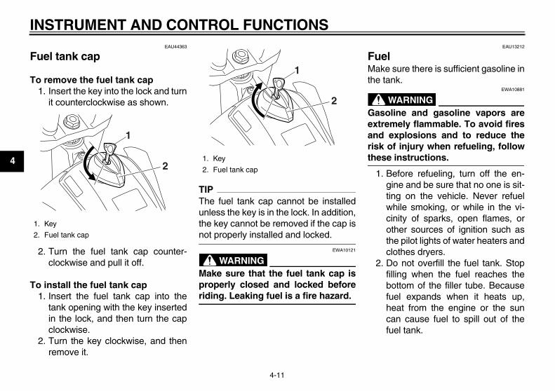
EAU44363
Fuel tank cap
To remove the fuel tank cap1. Insert the key into the lock and turn
it counterclockwise as shown.
2. Turn the fuel tank cap counter-clockwise and pull it off.
To install the fuel tank cap1. Insert the fuel tank cap into the
tank opening with the key insertedin the lock, and then turn the capclockwise.
2. Turn the key clockwise, and thenremove it.
TIPThe fuel tank cap cannot be installedunless the key is in the lock. In addition,the key cannot be removed if the cap isnot properly installed and locked.
WARNINGEWA10121
Make sure that the fuel tank cap isproperly closed and locked beforeriding. Leaking fuel is a fire hazard.
EAU13212
Fuel Make sure there is sufficient gasoline inthe tank.
WARNINGEWA10881
Gasoline and gasoline vapors areextremely flammable. To avoid firesand explosions and to reduce therisk of injury when refueling, followthese instructions.
1. Before refueling, turn off the en-gine and be sure that no one is sit-ting on the vehicle. Never refuelwhile smoking, or while in the vi-cinity of sparks, open flames, orother sources of ignition such asthe pilot lights of water heaters andclothes dryers.
2. Do not overfill the fuel tank. Stopfilling when the fuel reaches thebottom of the filler tube. Becausefuel expands when it heats up,heat from the engine or the suncan cause fuel to spill out of thefuel tank.
1. Key
2. Fuel tank cap
1
21. Key
2. Fuel tank cap
1
2
32D-9-28-E0.book 11 ページ 2011年6月29日 水曜日 午後5時28分

INSTRUMENT AND CONTROL FUNCTIONS
4-12
2
3
4
5
6
7
8
9
3. Wipe up any spilled fuel immedi-ately. NOTICE: Immediately wipeoff spilled fuel with a clean, dry,soft cloth, since fuel may deteri-orate painted surfaces or plasticparts.[ECA10071]
4. Be sure to securely close the fueltank cap.
WARNINGEWA15151
Gasoline is poisonous and cancause injury or death. Handle gaso-line with care. Never siphon gaso-line by mouth. If you should swallowsome gasoline or inhale a lot of gas-oline vapor, or get some gasoline in
your eyes, see your doctor immedi-ately. If gasoline spills on your skin,wash with soap and water. If gaso-line spills on your clothing, changeyour clothes.
EAU13391
NOTICEECA11400
Use only unleaded gasoline. The useof leaded gasoline will cause severedamage to internal engine parts,such as the valves and piston rings,as well as to the exhaust system.
Your Yamaha engine has been de-signed to use premium unleaded gaso-line with a research octane number of95 or higher. If knocking (or pinging) oc-curs, use a gasoline of a differentbrand. Use of unleaded fuel will extend
spark plug life and reduce maintenancecosts.
1. Maximum fuel level
2. Fuel tank filler tube
21
Recommended fuel:Premium unleaded gasoline only
Fuel tank capacity:7.6 L (2.01 US gal, 1.67 Imp.gal)
Fuel reserve amount (when the fuel level warning light comes on):
2.1 L (0.55 US gal, 0.46 Imp.gal)
32D-9-28-E0.book 12 ページ 2011年6月29日 水曜日 午後5時28分
INSTRUMENT AND CONTROL FUNCTIONS
4-13
1
2
3
4
5
6
7
8
9
EAU13433
Catalytic converter This model is equipped with a catalyticconverter in the exhaust system.
WARNINGEWA10862
The exhaust system is hot after op-eration. To prevent a fire hazard orburns: Do not park the vehicle near
possible fire hazards such asgrass or other materials thateasily burn.
Park the vehicle in a placewhere pedestrians or childrenare not likely to touch the hotexhaust system.
Make sure that the exhaust sys-tem has cooled down before do-ing any maintenance work.
Do not allow the engine to idlemore than a few minutes. Longidling can cause a build-up ofheat.
NOTICEECA10701
Use only unleaded gasoline. The useof leaded gasoline will cause unre-pairable damage to the catalytic
converter. EAU46281
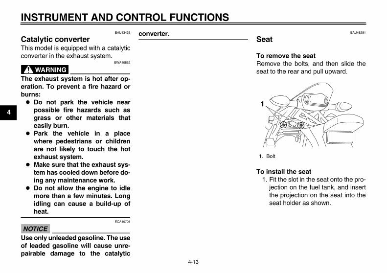
Seat
To remove the seatRemove the bolts, and then slide theseat to the rear and pull upward.
To install the seat1. Fit the slot in the seat onto the pro-
jection on the fuel tank, and insertthe projection on the seat into theseat holder as shown.
1. Bolt
1
32D-9-28-E0.book 13 ページ 2011年6月29日 水曜日 午後5時28分

INSTRUMENT AND CONTROL FUNCTIONS
4-14
2
3
4
5
6
7
8
9
2. Place the seat in the original posi-tion, and then tighten the bolts.
TIPMake sure that the seat is properly se-cured before riding.
EAU14282
Helmet holder
To open the helmet holder, insert thekey into the lock, and then turn the keyas shown.To lock the helmet holder, place it in theoriginal position, and then remove thekey. WARNING! Never ride with ahelmet attached to the helmet hold-er, since the helmet may hit objects,causing loss of control and possiblyan accident.[EWA10161]
EAU45202
Adjusting the front fork
WARNINGEWA10180
Always adjust both fork legs equal-ly, otherwise poor handling and lossof stability may result.
This front fork is equipped with rebounddamping force adjusting screws andcompression damping force adjustingscrews.
NOTICEECA10101
To avoid damaging the mechanism,do not attempt to turn beyond themaximum or minimum settings.
Rebound damping forceTo increase the rebound damping forceand thereby harden the rebound damp-ing, turn the adjusting screw on eachfork leg in direction (a). To decrease therebound damping force and therebysoften the rebound damping, turn theadjusting screw on each fork leg in di-rection (b).
1. Slot
2. Projection
3. Seat holder
2
32
1
1. Helmet holder
2. Open.
1
2
32D-9-28-E0.book 14 ページ 2011年6月29日 水曜日 午後5時28分
INSTRUMENT AND CONTROL FUNCTIONS
4-15
1
2
3
4
5
6
7
8
9
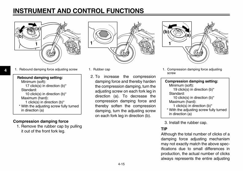
Compression damping force1. Remove the rubber cap by pulling
it out of the front fork leg.
2. To increase the compressiondamping force and thereby hardenthe compression damping, turn theadjusting screw on each fork leg indirection (a). To decrease thecompression damping force andthereby soften the compressiondamping, turn the adjusting screwon each fork leg in direction (b).
3. Install the rubber cap.
TIPAlthough the total number of clicks of adamping force adjusting mechanismmay not exactly match the above spec-ifications due to small differences inproduction, the actual number of clicksalways represents the entire adjusting
1. Rebound damping force adjusting screw
Rebound damping setting:Minimum (soft):
17 click(s) in direction (b)*Standard:
10 click(s) in direction (b)*Maximum (hard):
1 click(s) in direction (b)** With the adjusting screw fully turned
in direction (a)
1
(b)
(a)
1. Rubber cap
1
1. Compression damping force adjusting screw
Compression damping setting:Minimum (soft):
19 click(s) in direction (b)*Standard:
10 click(s) in direction (b)*Maximum (hard):
1 click(s) in direction (b)** With the adjusting screw fully turned
in direction (a)
1
(a)(b)
32D-9-28-E0.book 15 ページ 2011年6月29日 水曜日 午後5時28分
INSTRUMENT AND CONTROL FUNCTIONS
4-16
2
3
4
5
6
7
8
9
range. To obtain a precise adjustment,it would be advisable to check the num-ber of clicks of each damping force ad-justing mechanism and to modify thespecifications as necessary.
EAU14793
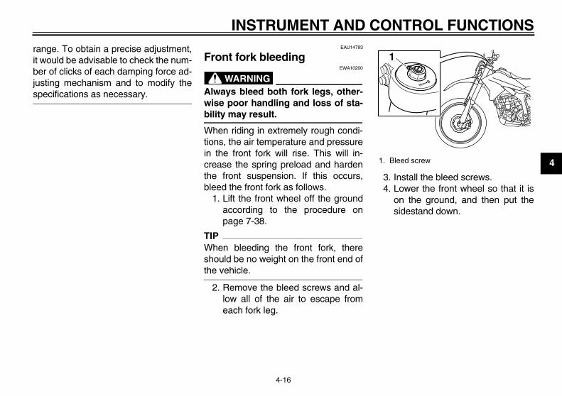
Front fork bleeding
WARNINGEWA10200
Always bleed both fork legs, other-wise poor handling and loss of sta-bility may result.
When riding in extremely rough condi-tions, the air temperature and pressurein the front fork will rise. This will in-crease the spring preload and hardenthe front suspension. If this occurs,bleed the front fork as follows.
1. Lift the front wheel off the groundaccording to the procedure onpage 7-38.
TIPWhen bleeding the front fork, thereshould be no weight on the front end ofthe vehicle.
2. Remove the bleed screws and al-low all of the air to escape fromeach fork leg.
3. Install the bleed screws.4. Lower the front wheel so that it is
on the ground, and then put thesidestand down.
1. Bleed screw
1
32D-9-28-E0.book 16 ページ 2011年6月29日 水曜日 午後5時28分

INSTRUMENT AND CONTROL FUNCTIONS
4-17
1
2
3
4
5
6
7
8
9
EAU45263
Adjusting the shock absorber assembly This shock absorber assembly isequipped with a spring preload adjust-ing ring, a rebound damping force ad-justing knob and a compressiondamping force adjusting screw.
NOTICEECA10101
To avoid damaging the mechanism,do not attempt to turn beyond themaximum or minimum settings.
Spring preloadSpring preload adjustment should bemade by a Yamaha dealer, since thisservice requires special tools and tech-nical skills. The specified settings arelisted below.The spring preload setting is deter-mined by measuring distance A, shownin the illustration. The shorter the dis-tance A is, the higher the spring pre-load; the longer distance A is, the lowerthe spring preload.
Rebound damping forceTo increase the rebound damping forceand thereby harden the rebound damp-ing, turn the adjusting knob in direction(a). To decrease the rebound dampingforce and thereby soften the rebounddamping, turn the adjusting knob in di-rection (b).
Compression damping forceTo increase the compression dampingforce and thereby harden the compres-sion damping, turn the adjusting screwin direction (a). To decrease the com-pression damping force and therebysoften the compression damping, turnthe adjusting screw in direction (b).
1. Distance A
Spring preload:Minimum (soft):
Distance A = 216.0 mm (8.50 in)Standard:
Distance A = 211.5 mm (8.33 in)Maximum (hard):
Distance A = 206.0 mm (8.11 in)
1
1. Rebound damping force adjusting knob
Rebound damping setting:Minimum (soft):
25 click(s) in direction (b)*Standard:
12 click(s) in direction (b)*Maximum (hard):
3 click(s) in direction (b)** With the adjusting knob fully turned in
direction (a)
(a)(b)
1
32D-9-28-E0.book 17 ページ 2011年6月29日 水曜日 午後5時28分

INSTRUMENT AND CONTROL FUNCTIONS
4-18
2
3
4
5
6
7
8
9TIPTo obtain a precise adjustment, it is ad-visable to check the actual total numberof clicks or turns of each damping forceadjusting mechanism. This adjustmentrange may not exactly match the spec-ifications listed due to small differences
in production.
WARNINGEWA10221
This shock absorber assembly con-tains highly pressurized nitrogengas. Read and understand the fol-lowing information before handlingthe shock absorber assembly. Do not tamper with or attempt to
open the cylinder assembly. Do not subject the shock ab-
sorber assembly to an openflame or other high heat source.This may cause the unit to ex-plode due to excessive gaspressure.
Do not deform or damage thecylinder in any way. Cylinderdamage will result in poordamping performance.
Do not dispose of a damaged orworn-out shock absorber as-sembly yourself. Take the shockabsorber assembly to a Yamahadealer for any service.
EAU41941
EXUP system This model is equipped with Yamaha’sEXUP (EXhaust Ultimate Power valve)system. This system boosts enginepower by means of a valve that regu-lates the inner diameter of the exhaustpipe. The EXUP system valve is con-stantly adjusted in accordance with theengine speed by a computer-controlledservomotor.
NOTICEECA15610
The EXUP system has been set andextensively tested at the Yamahafactory. Changing these settingswithout sufficient technical knowl-edge may result in poor perfor-mance of or damage to the engine.
1. Compression damping force adjusting screw
Compression damping setting:Minimum (soft):
12 click(s) in direction (b)*Standard:
10 click(s) in direction (b)*Maximum (hard):
1 click(s) in direction (b)** With the adjusting screw fully turned
in direction (a)
1
(a)(b)
32D-9-28-E0.book 18 ページ 2011年6月29日 水曜日 午後5時28分

INSTRUMENT AND CONTROL FUNCTIONS
4-19
1
2
3
4
5
6
7
8
9
EAU15305
Sidestand The sidestand is located on the left sideof the frame. Raise the sidestand orlower it with your foot while holding thevehicle upright.
TIPThe built-in sidestand switch is part ofthe ignition circuit cut-off system, whichcuts the ignition in certain situations.(See the following section for an expla-nation of the ignition circuit cut-off sys-tem.)
WARNINGEWA10241
The vehicle must not be ridden withthe sidestand down, or if the side-stand cannot be properly moved up(or does not stay up), otherwise thesidestand could contact the groundand distract the operator, resultingin a possible loss of control.Yamaha’s ignition circuit cut-offsystem has been designed to assistthe operator in fulfilling the respon-sibility of raising the sidestand be-fore starting off. Therefore, checkthis system regularly and have a
Yamaha dealer repair it if it does notfunction properly.
EAU44892
Ignition circuit cut-off system The ignition circuit cut-off system (com-prising the sidestand switch, clutchswitch and neutral switch) has the fol-lowing functions. It prevents starting when the trans-
mission is in gear and the side-stand is up, but the clutch lever isnot pulled.
It prevents starting when the trans-mission is in gear and the clutch le-ver is pulled, but the sidestand isstill down.
It cuts the running engine when thetransmission is in gear and the sid-estand is moved down.
Periodically check the operation of theignition circuit cut-off system accordingto the following procedure.
32D-9-28-E0.book 19 ページ 2011年6月29日 水曜日 午後5時28分
INSTRUMENT AND CONTROL FUNCTIONS
4-20
2
3
4
5
6
7
8
9
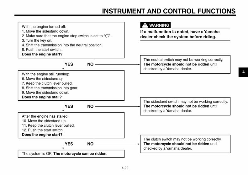
With the engine turned off:1. Move the sidestand down.2. Make sure that the engine stop switch is set to “3. Turn the key on. 4. Shift the transmission into the neutral position.5. Push the start switch.Does the engine start?
With the engine still running:6. Move the sidestand up.7. Keep the clutch lever pulled.8. Shift the transmission into gear.9. Move the sidestand down.Does the engine stall?
After the engine has stalled:10. Move the sidestand up.11. Keep the clutch lever pulled.12. Push the start switch.Does the engine start?
The system is OK. The motorcycle can be ridden.
The neutral switch may not be working correctly.The motorcycle should not be ridden untilchecked by a Yamaha dealer.
The sidestand switch may not be working correctly.The motorcycle should not be ridden untilchecked by a Yamaha dealer.
The clutch switch may not be working correctly.The motorcycle should not be ridden untilchecked by a Yamaha dealer.
YES NO
YES NO
YES NO
If a malfunction is noted, have a Yamahadealer check the system before riding.
WARNING
”.
32D-9-28-E0.book 20 ページ 2011年6月29日 水曜日 午後5時28分
5-1
1
2
3
4
5
6
7
8
9
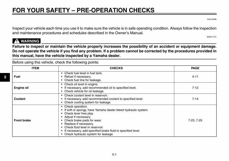
FOR YOUR SAFETY – PRE-OPERATION CHECKSEAU15596
Inspect your vehicle each time you use it to make sure the vehicle is in safe operating condition. Always follow the inspectionand maintenance procedures and schedules described in the Owner’s Manual.
WARNINGEWA11151
Failure to inspect or maintain the vehicle properly increases the possibility of an accident or equipment damage.Do not operate the vehicle if you find any problem. If a problem cannot be corrected by the procedures provided inthis manual, have the vehicle inspected by a Yamaha dealer.
Before using this vehicle, check the following points:
ITEM CHECKS PAGE
Fuel• Check fuel level in fuel tank.• Refuel if necessary.• Check fuel line for leakage.
4-11
Engine oil• Check oil level in engine.• If necessary, add recommended oil to specified level.• Check vehicle for oil leakage.
7-12
Coolant• Check coolant level in reservoir.• If necessary, add recommended coolant to specified level.• Check cooling system for leakage.
7-14
Front brake
• Check operation.• If soft or spongy, have Yamaha dealer bleed hydraulic system.• Check lever free play.• Adjust if necessary.• Check brake pads for wear.• Replace if necessary.• Check fluid level in reservoir.• If necessary, add specified brake fluid to specified level.• Check hydraulic system for leakage.
7-23, 7-25
32D-9-28-E0.book 1 ページ 2011年6月29日 水曜日 午後5時28分
FOR YOUR SAFETY – PRE-OPERATION CHECKS
5-2
2
3
4
5
6
7
8
9
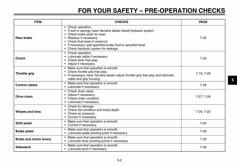
Rear brake
• Check operation.• If soft or spongy, have Yamaha dealer bleed hydraulic system.• Check brake pads for wear.• Replace if necessary.• Check fluid level in reservoir.• If necessary, add specified brake fluid to specified level.• Check hydraulic system for leakage.
7-25
Clutch
• Check operation.• Lubricate cable if necessary.• Check lever free play.• Adjust if necessary.
7-22
Throttle grip
• Make sure that operation is smooth.• Check throttle grip free play.• If necessary, have Yamaha dealer adjust throttle grip free play and lubricate
cable and grip housing.
7-19, 7-29
Control cables • Make sure that operation is smooth.• Lubricate if necessary. 7-29
Drive chain
• Check chain slack.• Adjust if necessary.• Check chain condition.• Lubricate if necessary.
7-27, 7-28
Wheels and tires
• Check for damage.• Check tire condition and tread depth.• Check air pressure.• Correct if necessary.
7-20, 7-22
Shift pedal • Make sure that operation is smooth.• Correct if necessary. 7-24
Brake pedal • Make sure that operation is smooth.• Lubricate pedal pivoting point if necessary. 7-30
Brake and clutch levers • Make sure that operation is smooth.• Lubricate lever pivoting points if necessary. 7-29
Sidestand • Make sure that operation is smooth.• Lubricate pivot if necessary. 7-30
ITEM CHECKS PAGE
32D-9-28-E0.book 2 ページ 2011年6月29日 水曜日 午後5時28分

FOR YOUR SAFETY – PRE-OPERATION CHECKS
5-3
1
2
3
4
5
6
7
8
9
Chassis fasteners • Make sure that all nuts, bolts and screws are properly tightened.• Tighten if necessary. —
Instruments, lights, signals and switches
• Check operation.• Correct if necessary. —
Sidestand switch • Check operation of ignition circuit cut-off system.• If system is not working correctly, have Yamaha dealer check vehicle. 4-19
ITEM CHECKS PAGE
32D-9-28-E0.book 3 ページ 2011年6月29日 水曜日 午後5時28分

6-1
2
3
4
5
6
7
8
9
OPERATION AND IMPORTANT RIDING POINTSEAU15951
Read the Owner’s Manual carefully tobecome familiar with all controls. Ifthere is a control or function you do notunderstand, ask your Yamaha dealer.
WARNINGEWA10271
Failure to familiarize yourself withthe controls can lead to loss of con-trol, which could cause an accidentor injury.
EAU46632
TIPThis model is equipped with: a lean angle sensor to stop the en-
gine in case of a turnover. In thiscase, the multi-function display in-dicates error code 30, but this isnot a malfunction. Turn the key to“OFF” and then to “ON” to clear theerror code. Failing to do so will pre-vent the engine from starting eventhough the engine will crank whenpushing the start switch.
an engine auto-stop system. Theengine stops automatically if leftidling for 20 minutes. In this case,the multi-function display indicateserror code 70, but this is not a mal-function. Push the start switch toclear the error code and to restartthe engine.
EAU45127
Starting the engine In order for the ignition circuit cut-offsystem to enable starting, one of thefollowing conditions must be met: The transmission is in the neutral
position. The transmission is in gear with
the clutch lever pulled and the sid-estand up.See page 4-19 for more informa-tion.
1. Turn the key to “ON” and makesure that the engine stop switch isset to “ ”.The following warning lightsshould come on for a few seconds,then go off. Fuel level warning light Coolant temperature warning
light Engine trouble warning light
NOTICEECA15484
If a warning light does not come oninitially when the key is turned to“ON”, or if a warning light remainson, see page 4-2 for the correspond-ing warning light circuit check.
32D-9-28-E0.book 1 ページ 2011年6月29日 水曜日 午後5時28分

OPERATION AND IMPORTANT RIDING POINTS
6-2
1
2
3
4
5
6
7
8
9
2. Shift the transmission into the neu-tral position. The neutral indicatorlight should come on. If not, ask aYamaha dealer to check the elec-trical circuit.
3. Start the engine by pushing thestart switch.If the engine fails to start, releasethe start switch, wait a few sec-onds, and then try again. Eachstarting attempt should be as shortas possible to preserve the bat-tery. Do not crank the engine morethan 10 seconds on any one at-tempt.
NOTICEECA11042
For maximum engine life, never ac-celerate hard when the engine iscold!
EAU16671
Shifting
Shifting gears lets you control theamount of engine power available forstarting off, accelerating, climbing hills,etc.The gear positions are shown in the il-lustration.
TIPTo shift the transmission into the neu-tral position, press the shift pedal downrepeatedly until it reaches the end of itstravel, and then slightly raise it.
NOTICEECA10260
Even with the transmission in
the neutral position, do notcoast for long periods of timewith the engine off, and do nottow the motorcycle for long dis-tances. The transmission isproperly lubricated only whenthe engine is running. Inade-quate lubrication may damagethe transmission.
Always use the clutch whilechanging gears to avoid damag-ing the engine, transmission,and drive train, which are notdesigned to withstand theshock of forced shifting.
1. Shift pedal
2. Neutral position
11
2345
N
2
6
32D-9-28-E0.book 2 ページ 2011年6月29日 水曜日 午後5時28分

OPERATION AND IMPORTANT RIDING POINTS
6-3
2
3
4
5
6
7
8
9
EAU16810
Tips for reducing fuel consumption Fuel consumption depends largely onyour riding style. Consider the followingtips to reduce fuel consumption: Shift up swiftly, and avoid high en-
gine speeds during acceleration. Do not rev the engine while shifting
down, and avoid high enginespeeds with no load on the engine.
Turn the engine off instead of let-ting it idle for an extended length oftime (e.g., in traffic jams, at trafficlights or at railroad crossings).
EAU16841
Engine break-in There is never a more important periodin the life of your engine than the periodbetween 0 and 1600 km (1000 mi). Forthis reason, you should read the follow-ing material carefully.Since the engine is brand new, do notput an excessive load on it for the first1600 km (1000 mi). The various parts inthe engine wear and polish themselvesto the correct operating clearances.During this period, prolonged full-throt-tle operation or any condition that mightresult in engine overheating must beavoided.
EAU17023
0–1000 km (0–600 mi)Avoid prolonged operation above 1/3throttle. NOTICE: After 1000 km (600mi) of operation, the engine oil mustbe changed, and the oil filter car-tridge or element replaced.[ECA11282]
1000–1600 km (600–1000 mi)Avoid prolonged operation above 1/2
throttle.
1600 km (1000 mi) and beyondThe vehicle can now be operated nor-mally.
NOTICEECA10270
If any engine trouble should occurduring the engine break-in period,immediately have a Yamaha dealercheck the vehicle.
32D-9-28-E0.book 3 ページ 2011年6月29日 水曜日 午後5時28分

OPERATION AND IMPORTANT RIDING POINTS
6-4
1
2
3
4
5
6
7
8
9
EAU17213
Parking When parking, stop the engine, andthen remove the key from the mainswitch.
WARNINGEWA10311
Since the engine and exhaustsystem can become very hot,park in a place where pedestri-ans or children are not likely totouch them and be burned.
Do not park on a slope or on softground, otherwise the vehiclemay overturn, increasing therisk of a fuel leak and fire.
Do not park near grass or otherflammable materials whichmight catch fire.
32D-9-28-E0.book 4 ページ 2011年6月29日 水曜日 午後5時28分

7-1
2
3
4
5
6
7
8
9
PERIODIC MAINTENANCE AND ADJUSTMENTEAU17244
Periodic inspection, adjustment, and lu-brication will keep your vehicle in thesafest and most efficient condition pos-sible. Safety is an obligation of the vehi-cle owner/operator. The most importantpoints of vehicle inspection, adjust-ment, and lubrication are explained onthe following pages.The intervals given in the periodicmaintenance charts should be simplyconsidered as a general guide undernormal riding conditions. However, de-pending on the weather, terrain, geo-graphical location, and individual use,the maintenance intervals may need tobe shortened.
WARNINGEWA10321
Failure to properly maintain the ve-hicle or performing maintenance ac-tivities incorrectly may increaseyour risk of injury or death duringservice or while using the vehicle. Ifyou are not familiar with vehicle ser-vice, have a Yamaha dealer performservice.
WARNINGEWA15122
Turn off the engine when performingmaintenance unless otherwisespecified. A running engine has moving
parts that can catch on bodyparts or clothing and electricalparts that can cause shocks orfires.
Running the engine while ser-vicing can lead to eye injury,burns, fire, or carbon monoxidepoisoning – possibly leading todeath. See page 2-2 for more in-formation about carbon monox-ide.
WARNINGEWA15460
Brake discs, calipers, drums, andlinings can become very hot duringuse. To avoid possible burns, letbrake components cool beforetouching them.
EAU17302
Emission controls not only function toensure cleaner air, but are also vital toproper engine operation and maximumperformance. In the following periodicmaintenance charts, the services relat-ed to emissions control are groupedseparately. These services requirespecialized data, knowledge, andequipment. Maintenance, replacement,or repair of the emission control devic-es and systems may be performed byany repair establishment or individualthat is certified (if applicable). Yamahadealers are trained and equipped toperform these particular services.
32D-9-28-E0.book 1 ページ 2011年6月29日 水曜日 午後5時28分

PERIODIC MAINTENANCE AND ADJUSTMENT
7-2
1
2
3
4
5
6
7
8
9
EAU35011
Owner’s tool kit
The owner’s tool kit is located inside thetool box.The service information included in thismanual and the tools provided in theowner’s tool kit are intended to assistyou in the performance of preventivemaintenance and minor repairs. How-ever, additional tools such as a torquewrench may be necessary to performcertain maintenance work correctly.
TIPIf you do not have the tools or experi-ence required for a particular job, havea Yamaha dealer perform it for you.
1. Tool box
1
32D-9-28-E0.book 2 ページ 2011年6月29日 水曜日 午後5時28分
PERIODIC MAINTENANCE AND ADJUSTMENT
7-3
2
3
4
5
6
7
8
9
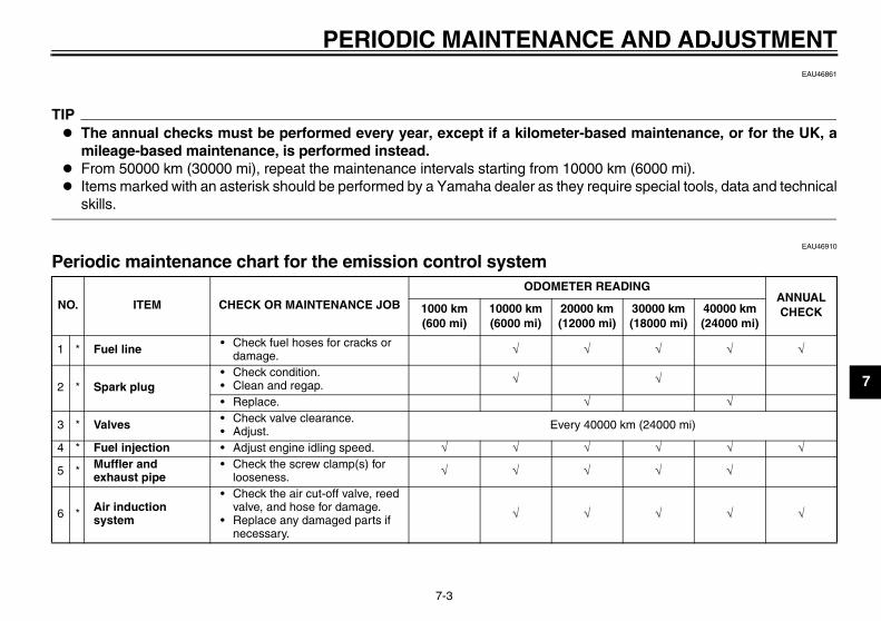
EAU46861
TIP The annual checks must be performed every year, except if a kilometer-based maintenance, or for the UK, a
mileage-based maintenance, is performed instead. From 50000 km (30000 mi), repeat the maintenance intervals starting from 10000 km (6000 mi). Items marked with an asterisk should be performed by a Yamaha dealer as they require special tools, data and technical
skills.
EAU46910
Periodic maintenance chart for the emission control system
NO. ITEM CHECK OR MAINTENANCE JOB
ODOMETER READINGANNUAL CHECK1000 km
(600 mi)10000 km (6000 mi)
20000 km (12000 mi)
30000 km (18000 mi)
40000 km (24000 mi)
1 * Fuel line • Check fuel hoses for cracks or damage.
2 * Spark plug• Check condition.• Clean and regap.
• Replace.
3 * Valves • Check valve clearance.• Adjust. Every 40000 km (24000 mi)
4 * Fuel injection • Adjust engine idling speed.
5 * Muffler and exhaust pipe
• Check the screw clamp(s) for looseness.
6 * Air induction system
• Check the air cut-off valve, reed valve, and hose for damage.
• Replace any damaged parts if necessary.
32D-9-28-E0.book 3 ページ 2011年6月29日 水曜日 午後5時28分

PERIODIC MAINTENANCE AND ADJUSTMENT
7-4
1
2
3
4
5
6
7
8
9
EAU1770C
General maintenance and lubrication chart
NO. ITEM CHECK OR MAINTENANCE JOB
ODOMETER READINGANNUAL CHECK1000 km
(600 mi)10000 km (6000 mi)
20000 km (12000 mi)
30000 km (18000 mi)
40000 km (24000 mi)
1 Air filter element• Clean. • Replace.
2 Clutch • Check operation.• Adjust.
3 * Front brake
• Check operation, fluid level and vehicle for fluid leakage.
• Adjust brake lever free play.
• Replace brake pads. Whenever worn to the limit
4 * Rear brake• Check operation, fluid level and
vehicle for fluid leakage.
• Replace brake pads. Whenever worn to the limit
5 * Brake hoses
• Check for cracks or damage.• Check for correct routing and
clamping.
• Replace. Every 4 years
6 * Wheels• Check runout, spoke tightness
and for damage.• Tighten spokes if necessary.
7 * Tires
• Check tread depth and for damage.
• Replace if necessary.• Check air pressure.• Correct if necessary.
8 * Wheel bearings • Check bearing for looseness or damage.
32D-9-28-E0.book 4 ページ 2011年6月29日 水曜日 午後5時28分

PERIODIC MAINTENANCE AND ADJUSTMENT
7-5
2
3
4
5
6
7
8
9
9 * Swingarm
• Check operation and for excessive play.
• Lubricate with lithium-soap-based grease. Every 50000 km (30000 mi)
10 Drive chain
• Check chain slack, alignment and condition.
• Adjust and lubricate chain with a special O-ring chain lubricant thoroughly.
Every 500 km (300 mi) and after washing the motorcycle, riding in the rain or riding in wet areas
11 * Steering bearings
• Check bearing play and steering for roughness.
• Lubricate with lithium-soap-based grease. Every 50000 km (30000 mi)
12 * Chassis fasteners• Make sure that all nuts, bolts
and screws are properly tightened.
13 Brake lever pivot shaft • Lubricate with silicone grease.
14 Brake pedal pivot shaft
• Lubricate with lithium-soap-based grease.
15 Clutch lever pivot shaft
• Lubricate with lithium-soap-based grease.
16 Sidestand• Check operation.• Lubricate with
lithium-soap-based grease.
17 * Sidestand switch • Check operation.
18 * Front fork • Check operation and for oil leakage.
19 * Shock absorber assembly
• Check operation and shock absorber for oil leakage.
NO. ITEM CHECK OR MAINTENANCE JOB
ODOMETER READINGANNUAL CHECK1000 km
(600 mi)10000 km (6000 mi)
20000 km (12000 mi)
30000 km (18000 mi)
40000 km (24000 mi)
32D-9-28-E0.book 5 ページ 2011年6月29日 水曜日 午後5時28分

PERIODIC MAINTENANCE AND ADJUSTMENT
7-6
1
2
3
4
5
6
7
8
9
20 *
Rear suspension relay arm and connecting arm pivoting points
• Check operation.
21 Engine oil• Change.• Check oil level and vehicle for oil
leakage. Every 5000 km (3000 mi)
22 Engine oil filter element • Replace.
23 * Cooling system
• Check coolant level and vehicle for coolant leakage.
• Change with ethylene glycol anti-freeze coolant. Every 3 years
24 * Front and rear brake switches • Check operation.
25 Moving parts and cables • Lubricate.
26 * Throttle grip
• Check operation.• Check throttle grip free play, and
adjust if necessary.• Lubricate cable and grip
housing.
27 * Lights, signals and switches
• Check operation.• Adjust headlight beam.
NO. ITEM CHECK OR MAINTENANCE JOB
ODOMETER READINGANNUAL CHECK1000 km
(600 mi)10000 km (6000 mi)
20000 km (12000 mi)
30000 km (18000 mi)
40000 km (24000 mi)
32D-9-28-E0.book 6 ページ 2011年6月29日 水曜日 午後5時28分

PERIODIC MAINTENANCE AND ADJUSTMENT
7-7
2
3
4
5
6
7
8
9
EAU18670
TIP The air filter needs more frequent service if you are riding in unusually wet or dusty areas. Hydraulic brake service
• Regularly check and, if necessary, correct the brake fluid level.• Every two years replace the internal components of the brake master cylinders and calipers, and change the brake
fluid.• Replace the brake hoses every four years and if cracked or damaged.
32D-9-28-E0.book 7 ページ 2011年6月29日 水曜日 午後5時28分

PERIODIC MAINTENANCE AND ADJUSTMENT
7-8
1
2
3
4
5
6
7
8
9
EAU18771
Removing and installing panels The panels shown need to be removedto perform some of the maintenancejobs described in this chapter. Refer tothis section each time a panel needs tobe removed and installed.
EAU45131
Panel A
To remove the panel1. Remove the seat. (See
page 4-13.)2. Remove the bolts and collars.
1. Panel A
2. Panel B
121. Panel C
1. Panel D
1
1
1. Bolt
2. Collar
21
21
32D-9-28-E0.book 8 ページ 2011年6月29日 水曜日 午後5時28分

PERIODIC MAINTENANCE AND ADJUSTMENT
7-9
2
3
4
5
6
7
8
9
3. Pull the front part of the panel out-ward, and then remove the panelby pulling it off.
To install the panel1. Place the panel in the original posi-
tion, and then install the collarsand bolts.
2. Install the seat.
Panel B
To remove the panel1. Remove the seat. (See
page 4-13.)2. Remove the bolt, and then remove
the panel as shown.
To install the panel1. Place the panel in the original posi-
tion, and then install the bolt.
2. Install the seat.
1. Bolt
2. Collar
3. Panel A
1 2
3
1. Bolt
2. Panel B
1
2
32D-9-28-E0.book 9 ページ 2011年6月29日 水曜日 午後5時28分

PERIODIC MAINTENANCE AND ADJUSTMENT
7-10
1
2
3
4
5
6
7
8
9
Panel C
To remove the panel1. Remove the bolts.
2. Lift the bottom of the panel slightly,and then slide the panel forward.
To install the panelPlace the panel in the original position,and then install the bolts.
Panel D
To remove the panel1. Remove the seat. (See
page 4-13.)2. Remove the bolt and washer, and
then remove the panel as shown.
To install the panel1. Place the panel in the original posi-
tion, and then install the washerand bolt.
2. Install the seat.
1. Panel C
2. Bolt
1
22
1. Bolt
2. Washer
3. Panel D
3
21
32D-9-28-E0.book 10 ページ 2011年6月29日 水曜日 午後5時28分
PERIODIC MAINTENANCE AND ADJUSTMENT
7-11
2
3
4
5
6
7
8
9
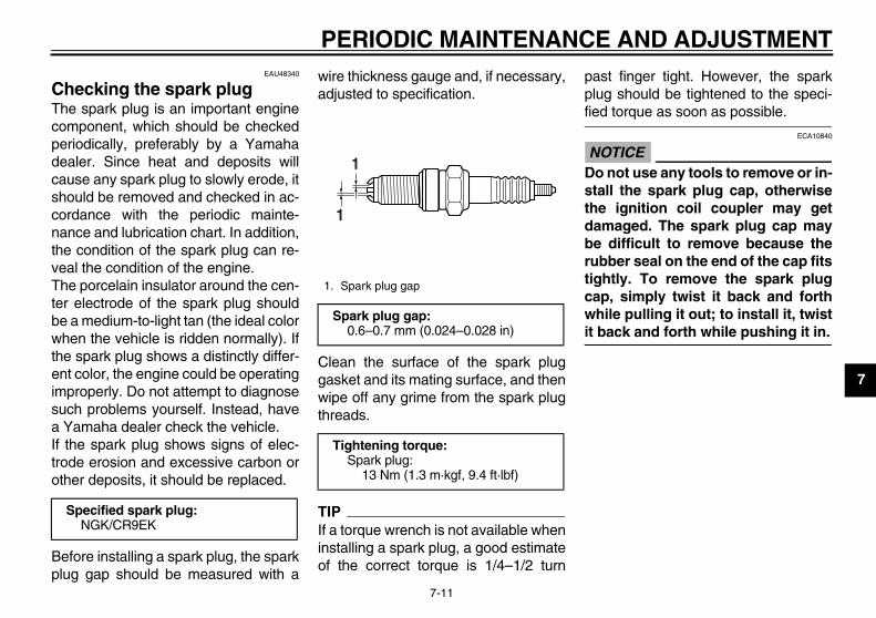
EAU48340
Checking the spark plug The spark plug is an important enginecomponent, which should be checkedperiodically, preferably by a Yamahadealer. Since heat and deposits willcause any spark plug to slowly erode, itshould be removed and checked in ac-cordance with the periodic mainte-nance and lubrication chart. In addition,the condition of the spark plug can re-veal the condition of the engine.The porcelain insulator around the cen-ter electrode of the spark plug shouldbe a medium-to-light tan (the ideal colorwhen the vehicle is ridden normally). Ifthe spark plug shows a distinctly differ-ent color, the engine could be operatingimproperly. Do not attempt to diagnosesuch problems yourself. Instead, havea Yamaha dealer check the vehicle.If the spark plug shows signs of elec-trode erosion and excessive carbon orother deposits, it should be replaced.
Before installing a spark plug, the sparkplug gap should be measured with a
wire thickness gauge and, if necessary,adjusted to specification.
Clean the surface of the spark pluggasket and its mating surface, and thenwipe off any grime from the spark plugthreads.
TIPIf a torque wrench is not available wheninstalling a spark plug, a good estimateof the correct torque is 1/4–1/2 turn
past finger tight. However, the sparkplug should be tightened to the speci-fied torque as soon as possible.
NOTICEECA10840
Do not use any tools to remove or in-stall the spark plug cap, otherwisethe ignition coil coupler may getdamaged. The spark plug cap maybe difficult to remove because therubber seal on the end of the cap fitstightly. To remove the spark plugcap, simply twist it back and forthwhile pulling it out; to install it, twistit back and forth while pushing it in.
Specified spark plug:NGK/CR9EK
1. Spark plug gap
Spark plug gap:0.6–0.7 mm (0.024–0.028 in)
Tightening torque:Spark plug:
13 Nm (1.3 m·kgf, 9.4 ft·lbf)
1
1
32D-9-28-E0.book 11 ページ 2011年6月29日 水曜日 午後5時28分

PERIODIC MAINTENANCE AND ADJUSTMENT
7-12
1
2
3
4
5
6
7
8
9
EAU45143
Engine oil and oil filter element The engine oil level should be checkedbefore each ride. In addition, the oilmust be changed and the oil filter ele-ment replaced at the intervals specifiedin the periodic maintenance and lubri-cation chart.
To check the engine oil level1. Place the vehicle on a level sur-
face and hold it in an upright posi-tion. A slight tilt to the side canresult in a false reading.
2. Start the engine, warm it up forseveral minutes, and then turn itoff.
3. Wait a few minutes until the oil set-tles, and then check the oil levelthrough the check window locatedat the bottom-right side of thecrankcase.
TIPThe engine oil should be between theminimum and maximum level marks.
4. If the engine oil is below the mini-mum level mark, add sufficient oilof the recommended type to raiseit to the correct level.
To change the engine oil (with or without oil filter element replace-ment)
1. Place the vehicle on a level sur-face.
2. Start the engine, warm it up forseveral minutes, and then turn itoff.
3. Place an oil pan under the engine
to collect the used oil.4. Remove the engine oil filler cap,
the engine oil drain bolt and itsgasket to drain the oil from thecrankcase.
TIPSkip steps 5–8 if the oil filter element isnot being replaced.
5. Remove the oil filter element coverby removing the bolts.
1. Engine oil filler cap
2. Maximum level mark
3. Minimum level mark
4. Engine oil level check window
1
23
4
1. Engine oil drain bolt
2. Gasket
1
2
32D-9-28-E0.book 12 ページ 2011年6月29日 水曜日 午後5時28分

PERIODIC MAINTENANCE AND ADJUSTMENT
7-13
2
3
4
5
6
7
8
9
6. Remove the oil filter element andO-rings.
7. Install a new oil filter element andnew O-rings.
TIPMake sure that the O-rings are properlyseated.
8. Install the oil filter element cover byinstalling the bolts, then tighteningthem to the specified torque.
9. Install the engine oil drain bolt andits new gasket, and then tightenthe bolt to the specified torque.
10. Refill with the specified amount ofthe recommended engine oil, andthen install and tighten the oil fillercap.
TIPBe sure to wipe off spilled oil on anyparts after the engine and exhaust sys-tem have cooled down.
NOTICEECA11620
In order to prevent clutch slip-page (since the engine oil alsolubricates the clutch), do notmix any chemical additives. Donot use oils with a diesel speci-fication of “CD” or oils of a high-er quality than specified. Inaddition, do not use oils labeled“ENERGY CONSERVING II” orhigher.
Make sure that no foreign mate-rial enters the crankcase.
11. Start the engine, and then let it idlefor several minutes while checking
1. Oil filter element cover
2. Oil filter element cover bolt
1. O-ring
2. Oil filter element
1
2
1
2
Tightening torque:Oil filter element cover bolt:
10 Nm (1.0 m·kgf, 7.2 ft·lbf)
Tightening torque:Engine oil drain bolt:
20 Nm (2.0 m·kgf, 14 ft·lbf)
Recommended oil:See page 9-1.
Oil quantity:Without oil filter element replace-ment:
1.30 L (1.37 US qt, 1.14 Imp.qt)With oil filter element replacement:
1.40 L (1.48 US qt, 1.23 Imp.qt)
32D-9-28-E0.book 13 ページ 2011年6月29日 水曜日 午後5時28分

PERIODIC MAINTENANCE AND ADJUSTMENT
7-14
1
2
3
4
5
6
7
8
9
it for oil leakage. If oil is leaking, im-mediately turn the engine off andcheck for the cause.
12. Turn the engine off, wait a few min-utes until the oil settles, and thencheck the oil level and correct it ifnecessary.
NOTICEECA11231
After changing the engine oil, makesure to check the oil pressure as de-scribed below. Loosen the bleed bolt. Start the engine and keep it
idling until oil flows out. If no oilcomes out after one minute,turn the engine off immediatelyso it will not seize. If this occurs,have a Yamaha dealer repair thevehicle.
After checking the oil pressure,tighten the bleed bolt to thespecified torque.
EAU20070
Coolant The coolant level should be checkedbefore each ride. In addition, the cool-ant must be changed at the intervalsspecified in the periodic maintenanceand lubrication chart.
EAU20254
To check the coolant level1. Place the vehicle on a level sur-
face and hold it in an upright posi-tion.
TIP The coolant level must be checked
on a cold engine since the levelvaries with engine temperature.
Make sure that the vehicle is posi-tioned straight up when checkingthe coolant level. A slight tilt to theside can result in a false reading.
2. Check the coolant level in the cool-ant reservoir.
TIPThe coolant should be between theminimum and maximum level marks.
1. Bleed bolt
Tightening torque:Bleed bolt:
10 Nm (1.0 m·kgf, 7.2 ft·lbf)
1
32D-9-28-E0.book 14 ページ 2011年6月29日 水曜日 午後5時28分

PERIODIC MAINTENANCE AND ADJUSTMENT
7-15
2
3
4
5
6
7
8
9
3. If the coolant is at or below theminimum level mark, remove pan-el C (See page 7-8.), remove thecoolant reservoir cap, add coolantto the maximum level mark, andthen install the reservoir cap andthe panel. WARNING! Removeonly the coolant reservoir cap.Never attempt to remove the ra-diator cap when the engine ishot.[EWA15161] NOTICE: If coolant isnot available, use distilled wateror soft tap water instead. Do notuse hard water or salt watersince it is harmful to the engine.If water has been used instead
of coolant, replace it with cool-ant as soon as possible, other-wise the cooling system will notbe protected against frost andcorrosion. If water has beenadded to the coolant, have aYamaha dealer check the anti-freeze content of the coolant assoon as possible, otherwise theeffectiveness of the coolant willbe reduced.[ECA10472]
EAU45155
To change the coolant1. Place the vehicle on a level sur-
face and let the engine cool if nec-essary.
2. Remove panels A and C. (Seepage 7-8.)
3. Place a container under the engineto collect the used coolant.
4. Remove the radiator cap retainingbolt and radiator cap. WARNING!Never attempt to remove the ra-diator cap when the engine ishot.[EWA10381]
5. Remove the coolant reservoir byremoving the bolts.
1. Maximum level mark
2. Minimum level mark
1
2
1. Coolant reservoir cap
Coolant reservoir capacity (up to the maximum level mark):
0.25 L (0.26 US qt, 0.22 Imp.qt)
1
1. Radiator cap
2. Radiator cap retaining bolt
2
1
32D-9-28-E0.book 15 ページ 2011年6月29日 水曜日 午後5時28分

PERIODIC MAINTENANCE AND ADJUSTMENT
7-16
1
2
3
4
5
6
7
8
9
6. Remove the coolant reservoir cap.
7. Drain the coolant from the coolantreservoir by turning it upside down.
8. Install the coolant reservoir byplacing it in the original position,
and then installing the bolts.9. Remove the coolant drain bolt and
its gasket to drain the cooling sys-tem.
10. After the coolant is completelydrained, thoroughly flush the cool-ing system with clean tap water.
11. Install the coolant drain bolt and itsnew gasket, and then tighten thebolt to the specified torque.
12. Pour the specified amount of therecommended coolant into the ra-
diator and reservoir.
13. Install the coolant reservoir cap.14. Install the radiator cap.15. Start the engine, let it idle for sev-
eral minutes, and then turn it off.16. Remove the radiator cap to check
the coolant level in the radiator. Ifnecessary, add sufficient coolantuntil it reaches the top of the radia-tor, and then install the radiatorcap and its retaining bolt.
17. Check the coolant level in the res-ervoir. If necessary, remove thecoolant reservoir cap, add coolantto the maximum level mark, andthen install the cap.
1. Bolt
2. Coolant reservoir
1. Coolant reservoir cap
1
2
11. Coolant drain bolt
2. Gasket
Tightening torque:Coolant drain bolt:
10 Nm (1.0 m·kgf, 7.2 ft·lbf)
12
Antifreeze/water mixture ratio:1:1
Recommended antifreeze:High-quality ethylene glycol anti-freeze containing corrosion inhibitors for aluminum engines
Coolant quantity:Radiator capacity (including all routes):
0.90 L (0.95 US qt, 0.79 Imp.qt)Coolant reservoir capacity (up to the maximum level mark):
0.25 L (0.26 US qt, 0.22 Imp.qt)
32D-9-28-E0.book 16 ページ 2011年6月29日 水曜日 午後5時28分
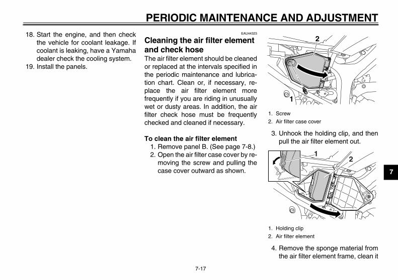
PERIODIC MAINTENANCE AND ADJUSTMENT
7-17
2
3
4
5
6
7
8
9
18. Start the engine, and then checkthe vehicle for coolant leakage. Ifcoolant is leaking, have a Yamahadealer check the cooling system.
19. Install the panels.
EAU44323
Cleaning the air filter element and check hose The air filter element should be cleanedor replaced at the intervals specified inthe periodic maintenance and lubrica-tion chart. Clean or, if necessary, re-place the air filter element morefrequently if you are riding in unusuallywet or dusty areas. In addition, the airfilter check hose must be frequentlychecked and cleaned if necessary.
To clean the air filter element1. Remove panel B. (See page 7-8.)2. Open the air filter case cover by re-
moving the screw and pulling thecase cover outward as shown.
3. Unhook the holding clip, and thenpull the air filter element out.
4. Remove the sponge material fromthe air filter element frame, clean it
1. Screw
2. Air filter case cover
1. Holding clip
2. Air filter element
2
1
12
32D-9-28-E0.book 17 ページ 2011年6月29日 水曜日 午後5時28分
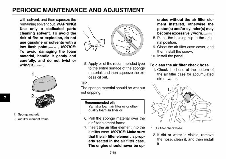
PERIODIC MAINTENANCE AND ADJUSTMENT
7-18
1
2
3
4
5
6
7
8
9
with solvent, and then squeeze theremaining solvent out. WARNING!Use only a dedicated partscleaning solvent. To avoid therisk of fire or explosion, do notuse gasoline or solvents with alow flash point.[EWA10431] NOTICE:To avoid damaging the foammaterial, handle it gently andcarefully, and do not twist orwring it.[ECA10511] 5. Apply oil of the recommended type
to the entire surface of the spongematerial, and then squeeze the ex-cess oil out.
TIPThe sponge material should be wet butnot dripping.
6. Pull the sponge material over theair filter element frame.
7. Insert the air filter element into theair filter case. NOTICE: Make surethat the air filter element is prop-erly seated in the air filter case.The engine should never be op-
erated without the air filter ele-ment installed, otherwise thepiston(s) and/or cylinder(s) maybecome excessively worn.[ECA10481]
8. Place the holding clip in the origi-nal position.
9. Close the air filter case cover, andthen install the screw.
10. Install the panel.
To clean the air filter check hose1. Check the hose at the bottom of
the air filter case for accumulateddirt or water.
2. If dirt or water is visible, removethe hose, clean it, and then installit.
1. Sponge material
2. Air filter element frame
1
2Recommended oil:
Yamaha foam air filter oil or other quality foam air filter oil
1. Air filter check hose
1
32D-9-28-E0.book 18 ページ 2011年6月29日 水曜日 午後5時28分
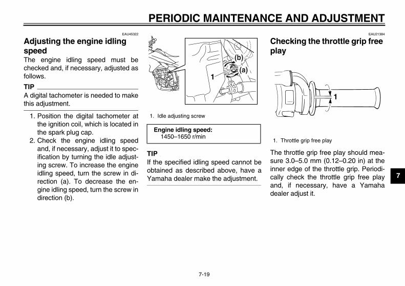
PERIODIC MAINTENANCE AND ADJUSTMENT
7-19
2
3
4
5
6
7
8
9
EAU45322
Adjusting the engine idling speed The engine idling speed must bechecked and, if necessary, adjusted asfollows.
TIPA digital tachometer is needed to makethis adjustment.
1. Position the digital tachometer atthe ignition coil, which is located inthe spark plug cap.
2. Check the engine idling speedand, if necessary, adjust it to spec-ification by turning the idle adjust-ing screw. To increase the engineidling speed, turn the screw in di-rection (a). To decrease the en-gine idling speed, turn the screw indirection (b).
TIPIf the specified idling speed cannot beobtained as described above, have aYamaha dealer make the adjustment.
EAU21384
Checking the throttle grip free play
The throttle grip free play should mea-sure 3.0–5.0 mm (0.12–0.20 in) at theinner edge of the throttle grip. Periodi-cally check the throttle grip free playand, if necessary, have a Yamahadealer adjust it.
1. Idle adjusting screw
Engine idling speed:1450–1650 r/min
1
(b)
(a)
1. Throttle grip free play
1
32D-9-28-E0.book 19 ページ 2011年6月29日 水曜日 午後5時28分

PERIODIC MAINTENANCE AND ADJUSTMENT
7-20
1
2
3
4
5
6
7
8
9
EAU21401
Valve clearance The valve clearance changes with use,resulting in improper air-fuel mixtureand/or engine noise. To prevent thisfrom occurring, the valve clearancemust be adjusted by a Yamaha dealerat the intervals specified in the periodicmaintenance and lubrication chart.
EAU21635
Tires To maximize the performance, durabil-ity, and safe operation of your motorcy-cle, note the following points regardingthe specified tires.
Tire air pressureThe tire air pressure should be checkedand, if necessary, adjusted before eachride.
WARNINGEWA10503
Operation of this vehicle with im-proper tire pressure may cause se-vere injury or death from loss ofcontrol. The tire air pressure must be
checked and adjusted on coldtires (i.e., when the temperatureof the tires equals the ambienttemperature).
The tire air pressure must be ad-justed in accordance with theriding speed and with the totalweight of rider, passenger, car-go, and accessories approvedfor this model.
WARNINGEWA10511
Never overload your vehicle. Opera-tion of an overloaded vehicle couldcause an accident.
Tire air pressure (measured on cold tires):
0–90 kg (0–198 lb):Front:
125 kPa (1.25 kgf/cm2, 18 psi)Rear:
175 kPa (1.75 kgf/cm2, 25 psi)90–185 kg (198–408 lb):
Front:150 kPa (1.50 kgf/cm2, 22 psi)
Rear:200 kPa (2.00 kgf/cm2, 29 psi)
Maximum load*:185 kg (408 lb)
* Total weight of rider, passenger, car-go and accessories
32D-9-28-E0.book 20 ページ 2011年6月29日 水曜日 午後5時28分
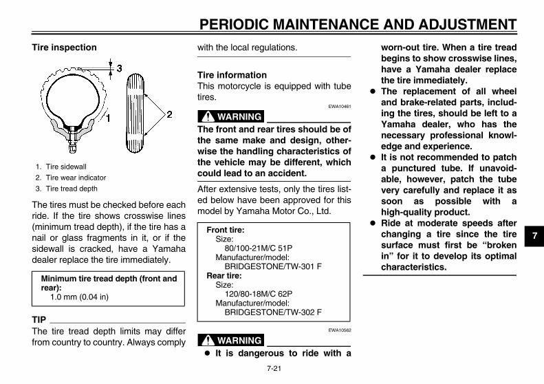
PERIODIC MAINTENANCE AND ADJUSTMENT
7-21
2
3
4
5
6
7
8
9
Tire inspection
The tires must be checked before eachride. If the tire shows crosswise lines(minimum tread depth), if the tire has anail or glass fragments in it, or if thesidewall is cracked, have a Yamahadealer replace the tire immediately.
TIPThe tire tread depth limits may differfrom country to country. Always comply
with the local regulations.
Tire informationThis motorcycle is equipped with tubetires.
WARNINGEWA10461
The front and rear tires should be ofthe same make and design, other-wise the handling characteristics ofthe vehicle may be different, whichcould lead to an accident.
After extensive tests, only the tires list-ed below have been approved for thismodel by Yamaha Motor Co., Ltd.
WARNINGEWA10562
It is dangerous to ride with a
worn-out tire. When a tire treadbegins to show crosswise lines,have a Yamaha dealer replacethe tire immediately.
The replacement of all wheeland brake-related parts, includ-ing the tires, should be left to aYamaha dealer, who has thenecessary professional knowl-edge and experience.
It is not recommended to patcha punctured tube. If unavoid-able, however, patch the tubevery carefully and replace it assoon as possible with ahigh-quality product.
Ride at moderate speeds afterchanging a tire since the tiresurface must first be “brokenin” for it to develop its optimalcharacteristics.
1. Tire sidewall
2. Tire wear indicator
3. Tire tread depth
Minimum tire tread depth (front and rear):
1.0 mm (0.04 in)
Front tire:Size:
80/100-21M/C 51PManufacturer/model:
BRIDGESTONE/TW-301 FRear tire:
Size:120/80-18M/C 62P
Manufacturer/model:BRIDGESTONE/TW-302 F
32D-9-28-E0.book 21 ページ 2011年6月29日 水曜日 午後5時28分
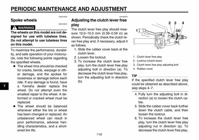
PERIODIC MAINTENANCE AND ADJUSTMENT
7-22
1
2
3
4
5
6
7
8
9
EAU21943
Spoke wheels
WARNINGEWA10610
The wheels on this model are not de-signed for use with tubeless tires.Do not attempt to use tubeless tireson this model.
To maximize the performance, durabil-ity, and safe operation of your motorcy-cle, note the following points regardingthe specified wheels. The wheel rims should be checked
for cracks, bends, warpage or oth-er damage, and the spokes forlooseness or damage before eachride. If any damage is found, havea Yamaha dealer replace thewheel. Do not attempt even thesmallest repair to the wheel. A de-formed or cracked wheel must bereplaced.
The wheel should be balancedwhenever either the tire or wheelhas been changed or replaced. Anunbalanced wheel can result inpoor performance, adverse han-dling characteristics, and a short-ened tire life.
EAU48373
Adjusting the clutch lever free play The clutch lever free play should mea-sure 10.0–15.0 mm (0.39–0.59 in) asshown. Periodically check the clutch le-ver free play and, if necessary, adjust itas follows.
1. Slide the rubber cover back at theclutch lever.
2. Loosen the locknut.3. To increase the clutch lever free
play, turn the clutch lever free playadjusting bolt in direction (a). Todecrease the clutch lever free play,turn the adjusting bolt in direction(b).
TIPIf the specified clutch lever free playcould be obtained as described above,skip steps 4–7.
4. Fully turn the adjusting bolt in di-rection (a) to loosen the clutch ca-ble.
5. Slide the rubber cover back furtherdown the clutch cable, and thenloosen the locknut.
6. To increase the clutch lever freeplay, turn the clutch lever free playadjusting nut in direction (a). Todecrease the clutch lever free play,
1. Clutch lever free play
2. Locknut (clutch lever)
3. Clutch lever free play adjusting bolt
4. Rubber cover
32
1
4
(a)
(b)
32D-9-28-E0.book 22 ページ 2011年6月29日 水曜日 午後5時28分

PERIODIC MAINTENANCE AND ADJUSTMENT
7-23
2
3
4
5
6
7
8
9
turn the adjusting nut in direction(b).
7. Tighten the locknut at the clutchcable, and then slide the rubbercover to its original position.
8. Tighten the locknut at the clutch le-ver, and then slide the rubber cov-er to its original position.
EAU48442
Adjusting the brake lever free play The brake lever free play should mea-sure 5.0–8.0 mm (0.20–0.31 in) asshown. Periodically check the brake le-ver free play and, if necessary, adjust itas follows.
1. Slide the rubber cover back at thebrake lever.
2. Loosen the locknut.3. To increase the brake lever free
play, turn the brake lever free playadjusting screw in direction (a). Todecrease the brake lever free play,turn the adjusting screw in direc-tion (b).
4. Tighten the locknut, and then slidethe rubber cover back to its originalposition.
WARNINGEWA10630
After adjusting the brake leverfree play, check the free playand make sure that the brake isworking properly.
A soft or spongy feeling in thebrake lever can indicate thepresence of air in the hydraulicsystem. If there is air in the hy-draulic system, have a Yamaha
1. Locknut (clutch cable)
2. Clutch lever free play adjusting nut (clutch cable)
3. Rubber cover
1
2 3(a)
(b)
1. Locknut
2. Brake lever free play adjusting screw
3. Brake lever free play
4. Rubber cover
3
12
4(b)
(a)
32D-9-28-E0.book 23 ページ 2011年6月29日 水曜日 午後5時28分

PERIODIC MAINTENANCE AND ADJUSTMENT
7-24
1
2
3
4
5
6
7
8
9
dealer bleed the system beforeoperating the motorcycle. Air inthe hydraulic system will dimin-ish the braking performance,which may result in loss of con-trol and an accident.
EAU44820
Checking the shift pedal The operation of the shift pedal shouldbe checked before each ride. If opera-tion is not smooth, have a Yamahadealer check the vehicle.
EAU22273
Brake light switches
The brake light, which is activated bythe brake pedal and brake lever, shouldcome on just before braking takes ef-fect. If necessary, adjust the rear brakelight switch as follows, but the frontbrake light switch should be adjustedby a Yamaha dealer.Turn the rear brake light switch adjust-ing nut while holding the rear brake lightswitch in place. To make the brake lightcome on earlier, turn the adjusting nutin direction (a). To make the brake lightcome on later, turn the adjusting nut indirection (b).
1. Rear brake light switch
2. Rear brake light switch adjusting nut
1
2
(b)
(a)
32D-9-28-E0.book 24 ページ 2011年6月29日 水曜日 午後5時28分

PERIODIC MAINTENANCE AND ADJUSTMENT
7-25
2
3
4
5
6
7
8
9
EAU22392
Checking the front and rear brake pads The front and rear brake pads must bechecked for wear at the intervals spec-ified in the periodic maintenance andlubrication chart.
EAU22430
Front brake pads
Each front brake pad is provided withwear indicator grooves, which allowyou to check the brake pad wear with-out having to disassemble the brake.To check the brake pad wear, checkthe wear indicator grooves. If a brakepad has worn to the point that the wearindicator grooves have almost disap-
peared, have a Yamaha dealer replacethe brake pads as a set.
EAU48070
Rear brake pads
Each rear brake pad is provided with awear indicator groove, which allowsyou to check the brake pad wear with-out having to disassemble the brake.To check the brake pad wear, checkthe wear indicator groove. If a brakepad has worn to the point that the wearindicator groove almost appears, havea Yamaha dealer replace the brakepads as a set.
EAU22581
Checking the brake fluid level Before riding, check that the brake fluidis above the minimum level mark.Check the brake fluid level with the topof the reservoir level. Replenish thebrake fluid if necessary.
Front brake
1. Brake pad wear indicator groove
1
1
1. Brake pad wear indicator groove
1
1. Minimum level mark
1
32D-9-28-E0.book 25 ページ 2011年6月29日 水曜日 午後5時28分

PERIODIC MAINTENANCE AND ADJUSTMENT
7-26
1
2
3
4
5
6
7
8
9
Rear brake
WARNINGEWA15990
Improper maintenance can result inloss of braking ability. Observethese precautions: Insufficient brake fluid may al-
low air to enter the brake sys-tem, reducing brakingperformance.
Clean the filler cap before re-moving. Use only DOT 4 brakefluid from a sealed container.
Use only the specified brake flu-id; otherwise, the rubber seals
may deteriorate, causing leak-age.
Refill with the same type ofbrake fluid. Adding a brake fluidother than DOT 4 may result in aharmful chemical reaction.
Be careful that water does notenter the brake fluid reservoirwhen refilling. Water will signifi-cantly lower the boiling point ofthe fluid and may result in vaporlock.
NOTICEECA17640
Brake fluid may damage painted sur-faces or plastic parts. Always cleanup spilled fluid immediately.
As the brake pads wear, it is normal forthe brake fluid level to gradually godown. A low brake fluid level may indi-cate worn brake pads and/or brake sys-tem leakage; therefore, be sure tocheck the brake pads for wear and thebrake system for leakage. If the brakefluid level goes down suddenly, have aYamaha dealer check the cause beforefurther riding.
EAU22731
Changing the brake fluid Have a Yamaha dealer change thebrake fluid at the intervals specified inthe TIP after the periodic maintenanceand lubrication chart. In addition, havethe oil seals of the master cylinders andcalipers as well as the brake hoses re-placed at the intervals listed below orwhenever they are damaged or leak-ing. Oil seals: Replace every two
years. Brake hoses: Replace every four
years.
1. Minimum level mark
Specified brake fluid:DOT 4
1
32D-9-28-E0.book 26 ページ 2011年6月29日 水曜日 午後5時28分

PERIODIC MAINTENANCE AND ADJUSTMENT
7-27
2
3
4
5
6
7
8
9
EAU22760
Drive chain slack The drive chain slack should bechecked before each ride and adjustedif necessary.
EAU47222
To check the drive chain slack1. Place the motorcycle on the side-
stand.
TIPWhen checking and adjusting the drivechain slack, there should be no weighton the motorcycle.
2. Shift the transmission into the neu-tral position.
3. Push on the drive chain at the cen-ter point between the chain ten-sioner and the chain supportmounting bolt with a force of 50 N(5.0 kgf, 11 lbf).
4. Measure drive chain slack be-tween the swingarm and the top ofthe chain link closest to the swing-arm as shown.
5. If the drive chain slack is incorrect,adjust it as follows.
EAU34317
To adjust the drive chain slackConsult a Yamaha dealer before ad-justing the drive chain slack.
1. Loosen the axle nut and the lock-nut on each side of the swingarm.
2. To tighten the drive chain, turn thedrive chain slack adjusting bolt oneach side of the swingarm in direc-tion (a). To loosen the drive chain,turn the adjusting bolt on each sideof the swingarm in direction (b),and then push the rear wheel for-
ward. NOTICE: Improper drivechain slack will overload the en-gine as well as other vital partsof the motorcycle and can leadto chain slippage or breakage.To prevent this from occurring,keep the drive chain slack with-in the specified limits.[ECA10571]
TIPUsing the alignment marks on eachside of the swingarm, make sure thatboth drive chain pullers are in the sameposition for proper wheel alignment.
Drive chain slack:8.0–13.0 mm (0.31–0.51 in)
1. Drive chain slack
2. Chain support mounting bolt
3. Chain tensioner
1
3
2
1. Axle nut
2. Locknut
3. Drive chain slack adjusting bolt
4. Alignment marks
5. Drive chain puller
1
5
324
(b)
(a)
32D-9-28-E0.book 27 ページ 2011年6月29日 水曜日 午後5時28分
PERIODIC MAINTENANCE AND ADJUSTMENT
7-28
1
2
3
4
5
6
7
8
9
3. Tighten the axle nut, then the lock-nuts to their specified torques.
4. Make sure that the drive chain pull-ers are in the same position, thedrive chain slack is correct, andthe drive chain moves smoothly.
EAU23025
Cleaning and lubricating the drive chain The drive chain must be cleaned andlubricated at the intervals specified inthe periodic maintenance and lubrica-tion chart, otherwise it will quickly wearout, especially when riding in dusty orwet areas. Service the drive chain asfollows.
NOTICEECA10583
The drive chain must be lubricatedafter washing the motorcycle, ridingin the rain or riding in wet areas.
1. Clean the drive chain with kero-sene and a small soft brush.NOTICE: To prevent damagingthe O-rings, do not clean thedrive chain with steam cleaners,high-pressure washers or inap-propriate solvents.[ECA11121]
2. Wipe the drive chain dry.3. Thoroughly lubricate the drive
chain with a special O-ring chainlubricant. NOTICE: Do not useengine oil or any other lubri-cants for the drive chain, as they
may contain substances thatcould damage the O-rings.[ECA11111]
Tightening torques:Axle nut:
125 Nm (12.5 m·kgf, 90 ft·lbf)Locknut:
16 Nm (1.6 m·kgf, 12 ft·lbf)
32D-9-28-E0.book 28 ページ 2011年6月29日 水曜日 午後5時28分
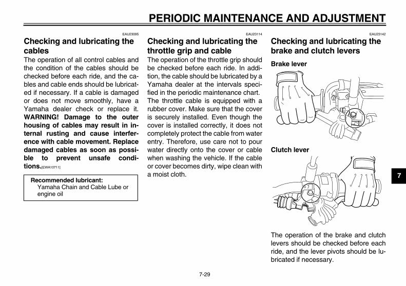
PERIODIC MAINTENANCE AND ADJUSTMENT
7-29
2
3
4
5
6
7
8
9
EAU23095
Checking and lubricating the cables The operation of all control cables andthe condition of the cables should bechecked before each ride, and the ca-bles and cable ends should be lubricat-ed if necessary. If a cable is damagedor does not move smoothly, have aYamaha dealer check or replace it.WARNING! Damage to the outerhousing of cables may result in in-ternal rusting and cause interfer-ence with cable movement. Replacedamaged cables as soon as possi-ble to prevent unsafe condi-tions.[EWA10711]
EAU23114
Checking and lubricating the throttle grip and cable The operation of the throttle grip shouldbe checked before each ride. In addi-tion, the cable should be lubricated by aYamaha dealer at the intervals speci-fied in the periodic maintenance chart.The throttle cable is equipped with arubber cover. Make sure that the coveris securely installed. Even though thecover is installed correctly, it does notcompletely protect the cable from waterentry. Therefore, use care not to pourwater directly onto the cover or cablewhen washing the vehicle. If the cableor cover becomes dirty, wipe clean witha moist cloth.
EAU23142
Checking and lubricating the brake and clutch levers
Brake lever
Clutch lever
The operation of the brake and clutchlevers should be checked before eachride, and the lever pivots should be lu-bricated if necessary.
Recommended lubricant:Yamaha Chain and Cable Lube or engine oil
32D-9-28-E0.book 29 ページ 2011年6月29日 水曜日 午後5時28分

PERIODIC MAINTENANCE AND ADJUSTMENT
7-30
1
2
3
4
5
6
7
8
9
EAU23182
Checking and lubricating the brake pedal
The operation of the brake pedalshould be checked before each ride,and the pedal pivot should be lubricat-ed if necessary.
EAU23202
Checking and lubricating the sidestand
The operation of the sidestand shouldbe checked before each ride, and thesidestand pivot and metal-to-metalcontact surfaces should be lubricated ifnecessary.
WARNINGEWA10731
If the sidestand does not move upand down smoothly, have a Yamahadealer check or repair it. Otherwise,the sidestand could contact theground and distract the operator, re-sulting in a possible loss of control.
Recommended lubricants:Brake lever:
Silicone greaseClutch lever:
Lithium-soap-based grease
Recommended lubricant:Lithium-soap-based grease
Recommended lubricant:Lithium-soap-based grease
32D-9-28-E0.book 30 ページ 2011年6月29日 水曜日 午後5時28分

PERIODIC MAINTENANCE AND ADJUSTMENT
7-31
2
3
4
5
6
7
8
9
EAUM1652
Lubricating the swingarm pivots The swingarm pivots must be lubricat-ed by a Yamaha dealer at the intervalsspecified in the periodic maintenanceand lubrication chart.
EAU23272
Checking the front fork The condition and operation of the frontfork must be checked as follows at theintervals specified in the periodic main-tenance and lubrication chart.
To check the conditionCheck the inner tubes for scratches,damage and excessive oil leakage.
To check the operation1. Place the vehicle on a level sur-
face and hold it in an upright posi-tion. WARNING! To avoid injury,securely support the vehicle sothere is no danger of it fallingover.[EWA10751]
2. While applying the front brake,push down hard on the handlebarsseveral times to check if the frontfork compresses and reboundssmoothly.
NOTICEECA10590
If any damage is found or the frontfork does not operate smoothly,have a Yamaha dealer check or re-pair it.
Recommended lubricant:Lithium-soap-based grease
32D-9-28-E0.book 31 ページ 2011年6月29日 水曜日 午後5時28分

PERIODIC MAINTENANCE AND ADJUSTMENT
7-32
1
2
3
4
5
6
7
8
9
EAU23283
Checking the steering Worn or loose steering bearings maycause danger. Therefore, the operationof the steering must be checked as fol-lows at the intervals specified in the pe-riodic maintenance and lubricationchart.
1. Place a stand under the engine toraise the front wheel off theground. (See page 7-38 for moreinformation.) WARNING! Toavoid injury, securely supportthe vehicle so there is no dangerof it falling over.[EWA10751]
2. Hold the lower ends of the frontfork legs and try to move them for-ward and backward. If any freeplay can be felt, have a Yamahadealer check or repair the steering.
EAU23291
Checking the wheel bearings
The front and rear wheel bearings mustbe checked at the intervals specified inthe periodic maintenance and lubrica-tion chart. If there is play in the wheelhub or if the wheel does not turnsmoothly, have a Yamaha dealer checkthe wheel bearings.
EAU46343
Battery
The battery is located behind panel D.(See page 7-8.)This model is equipped with a VRLA(Valve Regulated Lead Acid) battery.There is no need to check the electro-lyte or to add distilled water. However,the battery lead connections need to bechecked and, if necessary, securelytightened.
WARNINGEWA10760
Electrolyte is poisonous anddangerous since it contains sul-furic acid, which causes severe
1. Negative battery lead (black)
2. Positive battery lead (red)
3. Battery
3
2
1
32D-9-28-E0.book 32 ページ 2011年6月29日 水曜日 午後5時28分

PERIODIC MAINTENANCE AND ADJUSTMENT
7-33
2
3
4
5
6
7
8
9
burns. Avoid any contact withskin, eyes or clothing and al-ways shield your eyes whenworking near batteries. In caseof contact, administer the fol-lowing FIRST AID.• EXTERNAL: Flush with plenty
of water.• INTERNAL: Drink large quan-
tities of water or milk and im-mediately call a physician.
• EYES: Flush with water for 15minutes and seek promptmedical attention.
Batteries produce explosive hy-drogen gas. Therefore, keepsparks, flames, cigarettes, etc.,away from the battery and pro-vide sufficient ventilation whencharging it in an enclosedspace.
KEEP THIS AND ALL BATTER-IES OUT OF THE REACH OFCHILDREN.
To charge the batteryHave a Yamaha dealer charge the bat-tery as soon as possible if it seems to
have discharged. Keep in mind that thebattery tends to discharge more quicklyif the vehicle is equipped with optionalelectrical accessories.
NOTICEECA16521
To charge a VRLA (Valve RegulatedLead Acid) battery, a special (con-stant-voltage) battery charger is re-quired. Using a conventional batterycharger will damage the battery.
To store the battery1. If the model will not be used for
more than one month, remove thebattery, fully charge it, and thenplace it in a cool, dry place.NOTICE: When removing thebattery, be sure the key isturned to “OFF”, then discon-nect the negative lead beforedisconnecting the positivelead.[ECA16302]
2. If the battery will be stored for morethan two months, check it at leastonce a month and fully charge it ifnecessary.
3. Fully charge the battery before in-
stallation. NOTICE: When install-ing the battery, be sure the keyis turned to “OFF”, then con-nect the positive lead beforeconnecting the negativelead.[ECA16840]
NOTICEECA16530
Always keep the battery charged.Storing a discharged battery cancause permanent battery damage.
32D-9-28-E0.book 33 ページ 2011年6月29日 水曜日 午後5時28分

PERIODIC MAINTENANCE AND ADJUSTMENT
7-34
1
2
3
4
5
6
7
8
9
EAU23542
Replacing the fuses The main fuse is located behind panelD. (See page 7-8.)
The fuse box, which contains the fusesfor the individual circuits, is located be-hind panel C. (See page 7-8.)
If a fuse is blown, replace it as follows.1. Turn the key to “OFF” and turn off
the electrical circuit in question.2. Remove the blown fuse, and then
install a new fuse of the specifiedamperage. WARNING! Do notuse a fuse of a higher amperagerating than recommended toavoid causing extensive dam-age to the electrical system andpossibly a fire.[EWA15131]
3. Turn the key to “ON” and turn onthe electrical circuit in question tocheck if the device operates.
4. If a fuse immediately blows again,have a Yamaha dealer check theelectrical system.
1. Main fuse
2. Spare main fuse
2 1
1. Fuel injection system fuse
2. Radiator fan fuse
3. Backup fuse
4. Ignition fuse
5. Signaling system fuse
6. Headlight fuse
7. Spare fuse
7
1 2 3 4 5 6
Specified fuses:Main fuse:
30.0 AIgnition fuse:
7.5 ASignaling system fuse:
10.0 AHeadlight fuse:
15.0 ARadiator fan fuse:
7.5 ABackup fuse:
7.5 AFuel injection system fuse:
7.5 A
32D-9-28-E0.book 34 ページ 2011年6月29日 水曜日 午後5時28分

PERIODIC MAINTENANCE AND ADJUSTMENT
7-35
2
3
4
5
6
7
8
9
EAU45215
Replacing the headlight bulb This model is equipped with a halogenbulb headlight. If the headlight bulbburns out, replace it as follows.
NOTICEECA10650
Take care not to damage the follow-ing parts: Headlight bulb
Do not touch the glass part ofthe headlight bulb to keep it freefrom oil, otherwise the transpar-ency of the glass, the luminosityof the bulb, and the bulb life willbe adversely affected. Thor-oughly clean off any dirt and fin-gerprints on the headlight bulbusing a cloth moistened with al-cohol or thinner.
Headlight lensDo not affix any type of tintedfilm or stickers to the headlightlens.Do not use a headlight bulb of awattage higher than specified.
1. Remove the headlight cowling to-gether with the headlight unit byremoving the bolts and pulling up-ward as shown.
2. Disconnect the headlight coupler,and then remove the headlight
bulb cover.
3. Unhook the headlight bulb holder,and then remove the burnt-outbulb.
4. Place a new headlight bulb into po-
1. Do not touch the glass part of the bulb.
1. Bolt
11
1. Headlight coupler
2. Headlight bulb cover
1. Headlight bulb holder
1
2
1
32D-9-28-E0.book 35 ページ 2011年6月29日 水曜日 午後5時28分

PERIODIC MAINTENANCE AND ADJUSTMENT
7-36
1
2
3
4
5
6
7
8
9
sition, and then secure it with thebulb holder.
5. Install the bulb cover, and thenconnect the coupler.
6. Install the headlight cowling (to-gether with the headlight unit) byplacing it in the original position,and then installing the bolts.
7. Have a Yamaha dealer adjust theheadlight beam if necessary.
EAU24181
Tail/brake light This model is equipped with anLED-type tail/brake light.If the tail/brake light does not come on,have a Yamaha dealer check it.
EAU24204
Replacing a turn signal light bulb
1. Remove the turn signal light lensby removing the screw.
2. Remove the burnt-out bulb bypushing it in and turning it counter-clockwise.
1. Screw
2. Turn signal light lens
1
2
32D-9-28-E0.book 36 ページ 2011年6月29日 水曜日 午後5時28分

PERIODIC MAINTENANCE AND ADJUSTMENT
7-37
2
3
4
5
6
7
8
9
3. Insert a new bulb into the socket,push it in, and then turn it clock-wise until it stops.
4. Install the lens by installing thescrew. NOTICE: Do not over-tighten the screw, otherwise thelens may break.[ECA11191]
EAU24313
Replacing the license plate light bulb
1. Remove the license plate light unitby removing the screws.
2. Remove the license plate light bulbsocket (together with the bulb) bypulling it out.
3. Remove the burnt-out bulb by pull-ing it out.
4. Insert a new bulb into the socket.5. Install the socket (together with the
bulb) by pushing it in.6. Install the license plate light unit by
installing the screws.
1. Turn signal light bulb
1
1. Screw
1
1. License plate light unit
2. License plate light bulb socket
1
2
32D-9-28-E0.book 37 ページ 2011年6月29日 水曜日 午後5時28分

PERIODIC MAINTENANCE AND ADJUSTMENT
7-38
1
2
3
4
5
6
7
8
9
EAU45224
Replacing an auxiliary light bulb If the auxiliary light bulb burns out, re-place it as follows.
1. Remove the headlight unit. (Seepage 7-35.)
2. Remove the auxiliary light bulbsocket (together with the bulb) bypulling it out.
3. Remove the burnt-out bulb by pull-ing it out.
4. Insert a new bulb into the socket.5. Install the socket (together with the
bulb) by pushing it in.6. Install the headlight unit.
EAU24350
Supporting the motorcycle Since this model is not equipped with acenterstand, follow these precautionswhen removing the front and rearwheel or performing other maintenancerequiring the motorcycle to stand up-right. Check that the motorcycle is in astable and level position before startingany maintenance. A strong woodenbox can be placed under the engine foradded stability.
To service the front wheel1. Stabilize the rear of the motorcycle
by using a motorcycle stand or, ifan additional motorcycle stand isnot available, by placing a jack un-der the frame in front of the rearwheel.
2. Raise the front wheel off theground by using a motorcyclestand.
To service the rear wheelRaise the rear wheel off the ground byusing a motorcycle stand or, if a motor-cycle stand is not available, by placinga jack either under each side of the
frame in front of the rear wheel or undereach side of the swingarm.
1. Auxiliary light bulb socket
1
32D-9-28-E0.book 38 ページ 2011年6月29日 水曜日 午後5時28分

PERIODIC MAINTENANCE AND ADJUSTMENT
7-39
2
3
4
5
6
7
8
9
EAU24360
Front wheel
EAU45163
To remove the front wheel
WARNINGEWA10821
To avoid injury, securely support thevehicle so there is no danger of itfalling over.
1. Loosen the front wheel axle pinchbolts and axle nut.
2. Lift the front wheel off the groundaccording to the procedure in theprevious section “Supporting themotorcycle”.
3. Remove the axle nut.4. Pull the wheel axle out.5. Remove the spacers and the
wheel. NOTICE: Do not apply thebrake after the wheel has beenremoved together with thebrake disc, otherwise the brakepads will be forced shut.[ECA11071]
EAU45174
To install the front wheel1. Install the spacers into both sides
of the wheel hub. NOTICE: When
installing the spacers, be sureto install them on the correctside.[ECA17700]
2. Lift the wheel up between the forklegs.
TIPMake sure that there is enough spacebetween the brake pads before install-ing the brake caliper onto the brakedisc.
3. Insert the wheel axle from theright-hand side.
4. Install the axle nut.5. Lower the front wheel so that it is
on the ground, and then put thesidestand down.
6. Tighten the axle nut, and then thefront wheel axle pinch bolts to thespecified torques.
7. Push down hard on the handlebarseveral times to check for properfork operation.
1. Front wheel axle pinch bolt
2. Axle nut
2
1
1. Front wheel axle pinch bolt
2. Wheel axle
1
2
Tightening torques:Axle nut:
63 Nm (6.3 m·kgf, 46 ft·lbf)Front wheel axle pinch bolt:
23 Nm (2.3 m·kgf, 17 ft·lbf)
32D-9-28-E0.book 39 ページ 2011年6月29日 水曜日 午後5時28分

PERIODIC MAINTENANCE AND ADJUSTMENT
7-40
1
2
3
4
5
6
7
8
9
EAU25080
Rear wheel
EAU45183
To remove the rear wheel
WARNINGEWA10821
To avoid injury, securely support thevehicle so there is no danger of itfalling over.
1. Loosen the axle nut.
2. Lift the rear wheel off the groundaccording to the procedure onpage 7-38.
3. Remove the axle nut and washer.4. Loosen the locknut on each side of
the swingarm.
5. Turn the drive chain slack adjust-ing bolts fully in direction (a).
6. Push the wheel forward, and thenremove the drive chain from therear sprocket.
TIPThe drive chain does not need to bedisassembled in order to remove andinstall the rear wheel.
7. While supporting the brake caliper,pull the wheel axle out.
8. Remove the drive chain pullers,spacers and the wheel. NOTICE:Do not apply the brake after thewheel has been removed to-gether with the brake disc, oth-erwise the brake pads will beforced shut.[ECA11071]
EAU45193
To install the rear wheel1. Install the spacers into both sides
of the wheel hub. NOTICE: Wheninstalling the spacers, be sureto install them on the correctside.[ECA17700]
2. Install the wheel, drive chain pull-ers and the brake caliper bracketby inserting the wheel axle from
1. Axle nut
2. Washer
1
2
1. Drive chain slack adjusting bolt
2. Locknut
3. Brake caliper
12
3
(a)
1. Wheel axle
1
32D-9-28-E0.book 40 ページ 2011年6月29日 水曜日 午後5時28分

PERIODIC MAINTENANCE AND ADJUSTMENT
7-41
2
3
4
5
6
7
8
9
the left-hand side.
TIP Make sure that the retainer on the
brake caliper bracket is insertedinto the slot in the swingarm.
Make sure that there is enoughspace between the brake pads be-fore installing the wheel.
3. Install the drive chain onto the rearsprocket.
4. Install the washer and the axle nut.5. Lower the rear wheel so that it is
on the ground, and then put thesidestand down.
6. Adjust the drive chain slack. (See
page 7-27.)7. Tighten the axle nut, and then the
locknuts to their specified torques.
EAU25871
Troubleshooting Although Yamaha motorcycles receivea thorough inspection before shipmentfrom the factory, trouble may occur dur-ing operation. Any problem in the fuel,compression, or ignition systems, forexample, can cause poor starting andloss of power.The following troubleshooting chartsrepresent quick and easy proceduresfor checking these vital systems your-self. However, should your motorcyclerequire any repair, take it to a Yamahadealer, whose skilled technicians havethe necessary tools, experience, andknow-how to service the motorcycleproperly.Use only genuine Yamaha replace-ment parts. Imitation parts may look likeYamaha parts, but they are often inferi-or, have a shorter service life and canlead to expensive repair bills.
WARNINGEWA15141
When checking the fuel system, donot smoke, and make sure there areno open flames or sparks in the ar-ea, including pilot lights from water
1. Brake caliper bracket
2. Retainer
3. Slot
1
2
3
Tightening torques:Axle nut:
125 Nm (12.5 m·kgf, 90 ft·lbf)Locknut:
16 Nm (1.6 m·kgf, 12 ft·lbf)
32D-9-28-E0.book 41 ページ 2011年6月29日 水曜日 午後5時28分
PERIODIC MAINTENANCE AND ADJUSTMENT
7-42
1
2
3
4
5
6
7
8
9
heaters or furnaces. Gasoline orgasoline vapors can ignite or ex-plode, causing severe injury orproperty damage.
32D-9-28-E0.book 42 ページ 2011年6月29日 水曜日 午後5時28分
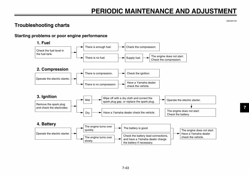
PERIODIC MAINTENANCE AND ADJUSTMENT
7-43
2
3
4
5
6
7
8
9
EAU42134
Troubleshooting charts
Starting problems or poor engine performance
Check the fuel level inthe fuel tank.
1. FuelThere is enough fuel.
There is no fuel.
Check the compression.
Supply fuel. The engine does not start. Check the compression.
Operate the electric starter.
2. CompressionThere is compression.
There is no compression.
Check the ignition.
Have a Yamaha dealercheck the vehicle.
Remove the spark plugand check the electrodes.
3. Ignition Wipe off with a dry cloth and correct thespark plug gap, or replace the spark plug.
Have a Yamaha dealer check the vehicle.
The engine does not start.Have a Yamaha dealercheck the vehicle.
The engine does not start.Check the battery.
Operate the electric starter.
4. BatteryThe engine turns over quickly.
The engine turns over slowly.
The battery is good.
Dry
Wet Operate the electric starter.
Check the battery lead connections,and have a Yamaha dealer chargethe battery if necessary.
32D-9-28-E0.book 43 ページ 2011年6月29日 水曜日 午後5時28分

PERIODIC MAINTENANCE AND ADJUSTMENT
7-44
1
2
3
4
5
6
7
8
9
Engine overheating
WARNINGEWA10400
Do not remove the radiator cap when the engine and radiator are hot. Scalding hot fluid and steam may beblown out under pressure, which could cause serious injury. Be sure to wait until the engine has cooled.
After removing the radiator cap retaining bolt, place a thick rag, like a towel, over the radiator cap, and thenslowly rotate the cap counterclockwise to the detent to allow any residual pressure to escape. When the hissingsound has stopped, press down on the cap while turning it counterclockwise, and then remove the cap.
TIPIf coolant is not available, tap water can be temporarily used instead, provided that it is changed to the recommended coolantas soon as possible.
Wait until the engine has cooled.
Check the coolant level in the reservoir and radiator.
The coolant level is OK.
The coolant level is low.Check the cooling systemfor leakage.
Have a Yamaha dealer checkand repair the cooling system.
Add coolant. (See TIP.)
Start the engine. If the engine overheats again, have a Yamaha dealer check and repair the cooling system.
There isleakage.
There is no leakage.
32D-9-28-E0.book 44 ページ 2011年6月29日 水曜日 午後5時28分
8-1
2
3
4
5
6
7
8
9
MOTORCYCLE CARE AND STORAGEEAU37833
Matte color caution
NOTICEECA15192
Some models are equipped withmatte colored finished parts. Besure to consult a Yamaha dealer foradvice on what products to use be-fore cleaning the vehicle. Using abrush, harsh chemical products orcleaning compounds when cleaningthese parts will scratch or damagetheir surface. Wax also should notbe applied to any matte colored fin-ished parts.
EAU26004
Care While the open design of a motorcyclereveals the attractiveness of the tech-nology, it also makes it more vulnera-ble. Rust and corrosion can developeven if high-quality components areused. A rusty exhaust pipe may go un-noticed on a car, however, it detractsfrom the overall appearance of a motor-cycle. Frequent and proper care doesnot only comply with the terms of thewarranty, but it will also keep your mo-torcycle looking good, extend its lifeand optimize its performance.
Before cleaning1. Cover the muffler outlet with a
plastic bag after the engine hascooled down.
2. Make sure that all caps and coversas well as all electrical couplersand connectors, including thespark plug cap, are tightly in-stalled.
3. Remove extremely stubborn dirt,like oil burnt onto the crankcase,with a degreasing agent and abrush, but never apply such prod-
ucts onto seals, gaskets, sprock-ets, the drive chain and wheelaxles. Always rinse the dirt and de-greaser off with water.
Cleaning
NOTICEECA10772
Avoid using strong acidic wheelcleaners, especially on spokedwheels. If such products areused on hard-to-remove dirt, donot leave the cleaner on the af-fected area any longer than in-structed. Also, thoroughly rinsethe area off with water, immedi-ately dry it, and then apply a cor-rosion protection spray.
Improper cleaning can damageplastic parts (such as cowlings,panels, windshields, headlightlenses, meter lenses, etc.) andthe mufflers. Use only a soft,clean cloth or sponge with wa-ter to clean plastic. However, ifthe plastic parts cannot be thor-oughly cleaned with water, di-luted mild detergent with watermay be used. Be sure to rinse
32D-9-28-E0.book 1 ページ 2011年6月29日 水曜日 午後5時28分

MOTORCYCLE CARE AND STORAGE
8-2
1
2
3
4
5
6
7
8
9
off any detergent residue usingplenty of water, as it is harmfulto plastic parts.
Do not use any harsh chemicalproducts on plastic parts. Besure to avoid using cloths orsponges which have been incontact with strong or abrasivecleaning products, solvent orthinner, fuel (gasoline), rust re-movers or inhibitors, brake flu-id, antifreeze or electrolyte.
Do not use high-pressure wash-ers or steam-jet cleaners sincethey cause water seepage anddeterioration in the following ar-eas: seals (of wheel and swing-arm bearings, fork and brakes),electric components (couplers,connectors, instruments,switches and lights), breatherhoses and vents.
For motorcycles equipped witha windshield: Do not use strongcleaners or hard sponges asthey will cause dulling orscratching. Some cleaning com-pounds for plastic may leavescratches on the windshield.
Test the product on a small hid-den part of the windshield tomake sure that it does not leaveany marks. If the windshield isscratched, use a quality plasticpolishing compound afterwashing.
After normal useRemove dirt with warm water, a milddetergent, and a soft, clean sponge,and then rinse thoroughly with cleanwater. Use a toothbrush or bottlebrushfor hard-to-reach areas. Stubborn dirtand insects will come off more easily ifthe area is covered with a wet cloth fora few minutes before cleaning.
After riding in the rain, near the sea oron salt-sprayed roadsSince sea salt or salt sprayed on roadsduring winter are extremely corrosive incombination with water, carry out thefollowing steps after each ride in therain, near the sea or on salt-sprayedroads.
TIPSalt sprayed on roads in the winter may
remain well into spring.
1. Clean the motorcycle with cold wa-ter and a mild detergent, after theengine has cooled down.NOTICE: Do not use warm watersince it increases the corrosiveaction of the salt.[ECA10791]
2. Apply a corrosion protection sprayon all metal, including chrome- andnickel-plated, surfaces to preventcorrosion.
After cleaning1. Dry the motorcycle with a chamois
or an absorbing cloth.2. Immediately dry the drive chain
and lubricate it to prevent it fromrusting.
3. Use a chrome polish to shinechrome, aluminum and stain-less-steel parts, including the ex-haust system. (Even the thermallyinduced discoloring of stain-less-steel exhaust systems can beremoved through polishing.)
4. To prevent corrosion, it is recom-mended to apply a corrosion pro-tection spray on all metal,
32D-9-28-E0.book 2 ページ 2011年6月29日 水曜日 午後5時28分

MOTORCYCLE CARE AND STORAGE
8-3
2
3
4
5
6
7
8
9
including chrome- and nickel-plat-ed, surfaces.
5. Use spray oil as a universal clean-er to remove any remaining dirt.
6. Touch up minor paint damagecaused by stones, etc.
7. Wax all painted surfaces.8. Let the motorcycle dry completely
before storing or covering it.
WARNINGEWA11131
Contaminants on the brakes or tirescan cause loss of control. Make sure that there is no oil or
wax on the brakes or tires. If necessary, clean the brake
discs and brake linings with aregular brake disc cleaner or ac-etone, and wash the tires withwarm water and a mild deter-gent. Before riding at higherspeeds, test the motorcycle’sbraking performance and cor-nering behavior.
NOTICEECA10800
Apply spray oil and wax spar-ingly and make sure to wipe off
any excess. Never apply oil or wax to any
rubber and plastic parts, buttreat them with a suitable careproduct.
Avoid using abrasive polishingcompounds as they will wearaway the paint.
TIP Consult a Yamaha dealer for ad-
vice on what products to use. Washing, rainy weather or humid
climates can cause the headlightlens to fog. Turning the headlighton for a short period of time willhelp remove the moisture from thelens.
EAU43202
Storage
Short-termAlways store your motorcycle in a cool,dry place and, if necessary, protect itagainst dust with a porous cover. Besure the engine and the exhaust sys-tem are cool before covering the motor-cycle.
NOTICEECA10810
Storing the motorcycle in apoorly ventilated room or cover-ing it with a tarp, while it is stillwet, will allow water and humid-ity to seep in and cause rust.
To prevent corrosion, avoiddamp cellars, stables (becauseof the presence of ammonia)and areas where strong chemi-cals are stored.
Long-termBefore storing your motorcycle for sev-eral months:
1. Follow all the instructions in the“Care” section of this chapter.
2. Fill up the fuel tank and add fuel
32D-9-28-E0.book 3 ページ 2011年6月29日 水曜日 午後5時28分

MOTORCYCLE CARE AND STORAGE
8-4
1
2
3
4
5
6
7
8
9
stabilizer (if available) to preventthe fuel tank from rusting and thefuel from deteriorating.
3. Perform the following steps to pro-tect the cylinder, piston rings, etc.from corrosion.a. Remove the spark plug cap
and spark plug.b. Pour a teaspoonful of engine oil
into the spark plug bore.c. Install the spark plug cap onto
the spark plug, and then placethe spark plug on the cylinderhead so that the electrodes aregrounded. (This will limit spark-ing during the next step.)
d. Turn the engine over severaltimes with the starter. (This willcoat the cylinder wall with oil.)
e. Remove the spark plug capfrom the spark plug, and theninstall the spark plug and thespark plug cap. WARNING! Toprevent damage or injuryfrom sparking, make sure toground the spark plug elec-trodes while turning the en-gine over.[EWA10951]
4. Lubricate all control cables and the
pivoting points of all levers andpedals as well as of the sidestand/centerstand.
5. Check and, if necessary, correctthe tire air pressure, and then liftthe motorcycle so that both of itswheels are off the ground. Alterna-tively, turn the wheels a little everymonth in order to prevent the tiresfrom becoming degraded in onespot.
6. Cover the muffler outlet with aplastic bag to prevent moisturefrom entering it.
7. Remove the battery and fullycharge it. Store it in a cool, dryplace and charge it once a month.Do not store the battery in an ex-cessively cold or warm place[less than 0 C (30 F) or morethan 30 C (90 F)]. For more in-formation on storing the battery,see page 7-32.
TIPMake any necessary repairs beforestoring the motorcycle.
32D-9-28-E0.book 4 ページ 2011年6月29日 水曜日 午後5時28分

9-1
2
3
4
5
6
7
8
9
SPECIFICATIONSEAU50915Dimensions:
Overall length: 2180 mm (85.8 in)
Overall width: 810 mm (31.9 in)
Overall height: 1230 mm (48.4 in)
Seat height: 930 mm (36.6 in)
Wheelbase: 1420 mm (55.9 in)
Ground clearance: 300 mm (11.81 in)
Minimum turning radius: 2300 mm (90.6 in)
Weight:Curb weight:
134 kg (295 lb)Engine:
Engine type: Liquid cooled 4-stroke, DOHC
Cylinder arrangement: Single cylinder
Displacement: 250 cm3
Bore stroke: 77.0 53.6 mm (3.03 2.11 in)
Compression ratio: 11.80 : 1
Starting system: Electric starter
Lubrication system: Wet sump
Engine oil:Recommended brand:
YAMALUBEType:
SAE 10W-30, 10W-40, 10W-50, 15W-40,20W-40 or 20W-50
Recommended engine oil grade: API service SG type or higher, JASO stan-dard MA
Engine oil quantity:Without oil filter element replacement:
1.30 L (1.37 US qt, 1.14 Imp.qt)With oil filter element replacement:
1.40 L (1.48 US qt, 1.23 Imp.qt)Cooling system:
Coolant reservoir capacity (up to the maxi-mum level mark):
0.25 L (0.26 US qt, 0.22 Imp.qt)Radiator capacity (including all routes):
0.90 L (0.95 US qt, 0.79 Imp.qt)Air filter:
Air filter element: Wet element
Fuel:Recommended fuel:
Premium unleaded gasoline onlyFuel tank capacity:
7.6 L (2.01 US gal, 1.67 Imp.gal)Fuel reserve amount:
2.1 L (0.55 US gal, 0.46 Imp.gal)Fuel injection:
Throttle body:ID mark:
3D71 10Spark plug(s):
Manufacturer/model: NGK/CR9EK
Spark plug gap: 0.6–0.7 mm (0.024–0.028 in)
Clutch:Clutch type:
Wet, multiple-discTransmission:
Primary reduction ratio: 3.120 (78/25)
Final drive: Chain
Secondary reduction ratio: 3.308 (43/13)
Transmission type: Constant mesh 6-speed
Operation: Left foot operation
–20 –10 0 10 20 30 40 50 ˚C
10 30 50 70 90 1100 130 ˚F
SAE 10W-30
SAE 15W-40
SAE 20W-40
SAE 20W-50
SAE 10W-40
SAE 10W-50
32D-9-28-E0.book 1 ページ 2011年6月29日 水曜日 午後5時28分

SPECIFICATIONS
9-2
1
2
3
4
5
6
7
8
9
Gear ratio:1st:
2.642 (37/14)2nd:
1.813 (29/16)3rd:
1.318 (29/22)4th:
1.040 (26/25)5th:
0.889 (24/27)6th:
0.786 (22/28)Chassis:
Frame type: Semi double cradle
Caster angle: 26.67
Trail: 111 mm (4.4 in)
Front tire:Type:
With tubeSize:
80/100-21M/C 51PManufacturer/model:
BRIDGESTONE/TW-301 FRear tire:
Type: With tube
Size: 120/80-18M/C 62P
Manufacturer/model: BRIDGESTONE/TW-302 F
Loading:Maximum load:
185 kg (408 lb)* (Total weight of rider, passenger, cargo
and accessories)Tire air pressure (measured on coldtires):
Loading condition: 0–90 kg (0–198 lb)Front:
125 kPa (1.25 kgf/cm2, 18 psi)Rear:
175 kPa (1.75 kgf/cm2, 25 psi)Loading condition:
90–185 kg (198–408 lb)Front:
150 kPa (1.50 kgf/cm2, 22 psi)Rear:
200 kPa (2.00 kgf/cm2, 29 psi)Front wheel:
Wheel type: Spoke wheel
Rim size: 21x1.60
Rear wheel:Wheel type:
Spoke wheelRim size:
18x2.15Front brake:
Type: Single disc brake
Operation: Right hand operation
Specified brake fluid: DOT 4
Rear brake:Type:
Single disc brakeOperation:
Right foot operationSpecified brake fluid:
DOT 4Front suspension:
Type: Telescopic fork
Spring/shock absorber type: Coil spring/oil damper
Wheel travel: 270.0 mm (10.63 in)
Rear suspension:Type:
Swingarm (link suspension)Spring/shock absorber type:
Coil spring/gas-oil damperWheel travel:
270.0 mm (10.63 in)Electrical system:
Ignition system: TCI
Charging system: AC magneto
Battery:Model:
YTZ7SVoltage, capacity:
12 V, 6.0 Ah
32D-9-28-E0.book 2 ページ 2011年6月29日 水曜日 午後5時28分

SPECIFICATIONS
9-3
2
3
4
5
6
7
8
9
Headlight:Bulb type:
Halogen bulbBulb voltage, wattage quantity:
Headlight: 12 V, 60 W/55 W
Tail/brake light: LED
Front turn signal light: 12 V, 10.0 W 2
Rear turn signal light: 12 V, 10.0 W 2
Auxiliary light: 12 V, 5.0 W 1
License plate light: 12 V, 5.0 W 1
Meter lighting: EL (Electroluminescent)
Neutral indicator light: LED
High beam indicator light: LED
Turn signal indicator light: LED
Fuel level warning light: LED
Coolant temperature warning light: LED
Engine trouble warning light: LED
Fuses:Main fuse:
30.0 A
Headlight fuse: 15.0 A
Signaling system fuse: 10.0 A
Ignition fuse: 7.5 A
Radiator fan fuse: 7.5 A
Fuel injection system fuse: 7.5 A
Backup fuse: 7.5 A
32D-9-28-E0.book 3 ページ 2011年6月29日 水曜日 午後5時28分

10-1
1
2
3
4
5
6
7
8
9
10
CONSUMER INFORMATIONEAU48612
Identification numbers Record the vehicle identification num-ber and model label information in thespaces provided below for assistancewhen ordering spare parts from aYamaha dealer or for reference in casethe vehicle is stolen.
VEHICLE IDENTIFICATION NUMBER:
MODEL LABEL INFORMATION:
EAU26400
Vehicle identification number
The vehicle identification number isstamped into the steering head pipe.Record this number in the space pro-vided.
TIPThe vehicle identification number isused to identify your motorcycle andmay be used to register your motorcy-cle with the licensing authority in yourarea.
EAU26460
Model label
The model label is affixed to the loca-tion shown. Record the information onthis label in the space provided. This in-formation will be needed when orderingspare parts from a Yamaha dealer.
1. Vehicle identification number
1
1. Model label
1
32D-9-28-E0.book 1 ページ 2011年6月29日 水曜日 午後5時28分

CONSUMER INFORMATION
10-2
2
3
4
5
6
7
8
9
10
EAU26570
Motorcycle noise regulation (for Australia) TAMPERING WITH NOISE CON-TROL SYSTEM PROHIBITED:Owners are warned that the law mayprohibit: The removal or rendering inopera-
tive by any person other than forpurposes of maintenance, repairor replacement, of any device orelement of design incorporatedinto any new vehicle for the pur-pose of noise control prior to itssale or delivery to the ultimate pur-chaser or while it is in use; and
The use of the vehicle after suchdevice or element of design hasbeen removed or rendered inoper-ative by any person.
32D-9-28-E0.book 2 ページ 2011年6月29日 水曜日 午後5時28分

INDEXA
Air filter element and check hose, cleaning .................................................7-17
Auxiliary light bulb, replacing ...................7-38B
Battery......................................................7-32Brake and clutch levers, checking and
lubricating ..............................................7-29Brake fluid, changing ...............................7-26Brake fluid level, checking .......................7-25Brake lever...............................................4-10Brake lever free play, adjusting................7-23Brake light switches .................................7-24Brake pedal..............................................4-10Brake pedal, checking and lubricating .....7-30
CCables, checking and lubricating .............7-29Care ...........................................................8-1Catalytic converter ...................................4-13Clutch lever ................................................4-9Clutch lever free play, adjusting...............7-22Coolant.....................................................7-14Coolant temperature warning light .............4-2
DDimmer switch ...........................................4-9Drive chain, cleaning and lubricating .......7-28Drive chain slack......................................7-27
EEngine break-in..........................................6-3Engine idling speed..................................7-19Engine oil and oil filter element ................7-12Engine stop switch .....................................4-9Engine trouble warning light.......................4-3EXUP system...........................................4-18
FFront and rear brake pads, checking....... 7-25Front fork, adjusting................................. 4-14Front fork, bleeding.................................. 4-16Front fork, checking ................................. 7-31Fuel.......................................................... 4-11Fuel consumption, tips for reducing........... 6-3Fuel level warning light .............................. 4-2Fuel tank cap........................................... 4-11Fuses, replacing ...................................... 7-34
HHandlebar switches ................................... 4-8Headlight bulb, replacing ......................... 7-35Helmet holder .......................................... 4-14High beam indicator light ........................... 4-2Horn switch................................................ 4-9
IIdentification numbers ............................. 10-1Ignition circuit cut-off system ................... 4-19Indicator lights and warning lights ............. 4-2
LLabels, location.......................................... 1-1License plate light bulb, replacing ........... 7-37
MMain switch/steering lock........................... 4-1Maintenance and lubrication, periodic ....... 7-4Maintenance, emission control system...... 7-3Matte color, caution ................................... 8-1Model label .............................................. 10-1Multi-function display ................................. 4-3
NNeutral indicator light................................. 4-2Noise regulation (for Australia) ................ 10-2
PPanels, removing and installing ................ 7-8Parking ...................................................... 6-4Part locations ............................................ 3-1
SSafety information ..................................... 2-1Seat......................................................... 4-13Shifting ...................................................... 6-2Shift pedal ............................................... 4-10Shift pedal, checking ............................... 7-24Shock absorber assembly, adjusting ...... 4-17Sidestand ................................................ 4-19Sidestand, checking and lubricating........ 7-30Spark plug, checking............................... 7-11Specifications ............................................ 9-1Starting the engine .................................... 6-1Start switch................................................ 4-9Steering, checking................................... 7-32Storage...................................................... 8-3Supporting the motorcycle ...................... 7-38Swingarm pivots, lubricating ................... 7-31
TTail/brake light......................................... 7-36Throttle grip and cable, checking and
lubricating ............................................. 7-29Throttle grip free play, checking .............. 7-19Tires ........................................................ 7-20Tool kit....................................................... 7-2Troubleshooting ...................................... 7-41Troubleshooting charts............................ 7-43Turn signal indicator light .......................... 4-2Turn signal light bulb, replacing .............. 7-36Turn signal switch ..................................... 4-9
32D-9-28-E0.book 3 ページ 2011年6月29日 水曜日 午後5時28分

INDEXV
Valve clearance .......................................7-20Vehicle identification number...................10-1
WWheel bearings, checking .......................7-32Wheel (front)............................................7-39Wheel (rear).............................................7-40Wheels.....................................................7-22
32D-9-28-E0.book 4 ページ 2011年6月29日 水曜日 午後5時28分

32D-9-28-E0.book 5 ページ 2011年6月29日 水曜日 午後5時28分


PRINTED ON RECYCLED PAPER PRINTED IN JAPAN2011.08-0.1×1 !
(E)