wrdc-tr-90-4020 ad-a220 794 - dtic. · pdf filewrdc-tr-90-4020 ad-a220 794 durable heart...
TRANSCRIPT

WRDC-TR-90-4020
AD-A220 794
DURABLE HEART DIAPHRAGM FROM ORDERED POLYMER FILMS
Anthony P. Lioi, Ph.D.
Nu-Tech Industries, Inc.
5905 Wolf Creek PikeDayton, OH 45415
May 1990
Final Report for Period July 1988 - November 1989
Approved for Public Release; Distribution is Unlimited
DTICS I" r ,019,
MATERIALS LABORATORY
WRIGHT RESEARCH AND DEVELOPMENT CENTERAIR FORCE SYSTEMS COMMANDWRIGHT-PATTERSON ATR FORCE BASE, OHIO 45433-6533
o/ - " ~l...

NOTICE
When Government drawings, specifications, or other data are used forany purpose other than in connection with a definitely Government-relatedprocurement, the United States Government incurs no responsibility or anyobligation whatsoever. The fact that the government may have formulated orin any way supplied the said drawings, specifications, or other data, is notto be regarded by implication, or otherwise in any manner construed, aslicensing the holder, or any other person or corporation; or as conveyingany rights or permission to manufacture, use, or sell any patented inventionthat may in any way be related thereto.
This report is releasable to the National Technical Information Service(NTIS). At NTIS, it will be available to the general public, includingforeign nations.
This technical report has been reviewed and is approved for publica-tion.
T. E. HELMINIAK, ChiefPolymer BranchNonmetallic Materials Division
FOR THE CO~t4AhDER
-M RILL _L.--IO . tr
No tallic Materis Division
If your address has changed, if you wish to be removed from our mailinglist, or if the addressee is no longer employed by your organization pleasenotify wRDC/MjBp, WPAFB, OH 45433-6533 to help us maintain a currentmailing list.
Copies of this report should not be returned unless return is required bysecurity considerations, contractual obligations, or notice on a specificdocument.

UNCLASSIFIEDSECURITY CLASSIF-ICATION OF THIS PAGE
Form ApprovedREPORT DOCUMENTATION PAGE OMB No. 0704-0188
la. REPORT SECURITY CLASSIFICATION lb. RESTRICTIVE MARKINGSUnclassified
2&. SECURITY CLASSIFICATION AUTHORITY 3. DISTRIBUTION/AVAILABILITY OF REPORTApproved for Public Release; Distribution is
2b. DECLASSIFICATION / DOWNGRADING SCHEDULE Unlimited.
4. PERFORMING ORGANIZATION REPORT NUMBER(S) S. MONITORING ORGANIZATION REPORT NUMBER(S)
WRDC-TR-90-4020
6a, NAME OF PERFORMING ORGANIZATION 6b. OFFICE SYMBOL 7a. NAME OF MONITORING ORGANIZATION(If applicable) Materials Laboratory (VRDC/I.BP)
Nu-Tech Industries, Inc. Wright Pesearch and Development Center6c. ADDRESS (City, State, and ZIPCode) 7b. ADDRESS (City, State, and ZIP Code)
5905 Wolf Creek PikeDayton, OH 45415 Wright Patterson, AFB, OH 45433-6533
8a. NAME OF FUNDING/SPONSORING 8b. OFFICE SYMBOL 9. PROCUREMENT INSTRUMENT IDENTIFICATION NUMBERORGANIZATION (If applicable)WRDC/MLBP I WRDC/MLBP F33615-88-C-5468
8c. ADDRESS (City, State, and ZIPCode) 10. SOURCE OF FUNDING NUMBERSPROGRAM PROJECT TASK WORK UNIT
WRDC/MLBP ELEMENT NO. NO. NO ACCESSION NO.
Wright Patterson AFB, OH 45433-6503 65502F 3005 51 95
11. TITLE (include Security Classification)
Durable Heart Diaphragm from Ordered Polymer Films
12. PERSONAL AUTHOR(S)Anthony P. Lioi, Ph.D.
13a. TYPE OF REPORT 13b. TIME COVERED 14. DATE OF REPORT (Year, Month, Day) 15. PAGE COUNTFinal FROM88JuI25 TO8N251 1990 May 43
16. SUPPLEMENTARY NOTATION
17. COSATI CODES 18. SUBJECT TERMS (Continue on reverse if necessary and identify by block number)FIELD GROUP SUB-GROUP Ordered Polymer Films Accelerated Flex Life Tester
Artificial Heart Interpenetrating NetworkFlexible Film
19. ABSTRACT (Continue on reverse if necessary and identify by block number)The purpose of this Phase I SBIR study was to investigate the feasibility of using theordered polymer poly-p-phenylene benzobisthiazole (PBZT) in high flex life applications.Applications of particular interest include biomedical applications such as theartificial heart or prosthetic heart valves. An accelerated flex life test rig based ona vibration principle was developed that was capable of subjecting film samples to over 3million flexural cycles per 24 hr period. Film samples were prepared of neat PBZT and ofPBZT in an interpenetrating network (IPN) with silicone and with polyurethane. The IPNwith polyurethane was also subjected to biocompatibility screening tests.
The results demonstrated the capability of the accelerated life test rig to provide highcycle rate and adequate flexure to fatigue the film samples. The test was run for 100million cycles. Information obtained indicated that flex life of PBZT was improved byforming an IPN with a polyurethane. Biocompatibility screening tests demonstrated
20 DISTRIBUTION/AVAILABILITY OF ABSTRACT 21. ABSTRACT SECURITY CLASSIFICATIONM UNCLASSIFIED/UNLIMITED L' SAME AS RPT. C DTIC USERS Unclassified
22a. NAME OF RESPONSIBLE INDIVIDUAL 22b. TELEPHONE (include Area Code) 22c. OFFICE SYMBOLTed lelminiak ,(513) 255-9155 WRDC/ILBP
DDForm 1473, JUN 86 Previous edltlons are obsolete. SECURITY CLASSIFICATION OF THIS PAGE
UNCLASS I F I ED
Block #19 -- ABSTRACT CONTINUED
feasibility of using the material in contact with blood.
The study indicated there is a potential for a high flex life material to be made fromordered polymers formed in an IPN with polyurethane. Since other ordered polymers of thesame family have an even greater potential for high flex life, the results of this studysuggest that a superior material for high flex life applications may be achieved.Aerospace potential includes use of these materials in light weight survivable fuel tanksand conduits, cryogenic fluid vessels, structural skins and a wide variety of hydraulicand pneumatic system components.

TABLE OF CONTENTS
PAGEA) PURPOSE OF THE WORK. ..... ...................... 1
B) DESCRIPTION OF THE WORK PERFORMED. ..... ............... 3B.1 DEVELOPMENT OF A FLEX LIFE TEST RIG. ................. 3B.2 TEST RIG DESIGN RATIONALE ..... ................. 3B.3 SELECTION OF INDIVIDUAL TEST RIG COLMPONENTS. ............ 7B.4 PREPARATION OF PBZT SAMPLES. .................... 12B.5 BIOCOMPATIBILITY TESTING .. .................. .. 16B.6 FILM SAMPLE TEST PREPARATIONS AND EXAMINATION PROCEDURES. .... .20
C) RESULTS. ...... ........................... 22C.1 TEST RIG PERFORMANCE RESULTS .. ................... 22C.2 FILM SAMPLE PREPARATION RESULTS ...... ............. 26C.3 BIOCOMPATIBILITY TEST RESULTS. ................... 27C.4 FILM SAIMPLE FLEXURAL FATIGUE TEST RESULTS ....... ...... 31
D) RECOMMENDATIONS FOR FUTURE WORK .. .................... 37
E) LITERATURE CITED. .................. ..........38
Aicv~s5Iof Fo r
vi: T'cc3
;j.c~j~Al~yCodes
u, ,0 t ia

0 DURABLE HEART DIAPHRAGM FROM ORDERED POLYMER FILMS
A PHASE I, SBIR FINAL RESEARCH AND DEVELOPMENT REPORT
A) PURPOSE OF THE WORK
Introduction - The ordered polymer poly-p-phenylene benzobisthiazole (PBZT)is an ordered polymer developed by the U.S. Air Force for aerospaceapplications. Although this ordered polymer was developed for high strength,there is reason to believe, based on its microstructure, that the material mayhave excellent fatigue resistance. It is also possible that the PBZT incombination with other materials, (for example in combination with polyurethanein an inter-penetrating network or IPN), might yield a superior material forhigh flex life applications. In aerospace applications, the thin tough filmscould be used for light weight survivable fuel tanks and conduits, cryogenicfluid vessels, structural skins, and a wide variety of hydraulic and pneumaticsystem components. There are also biomedical applications such as flexingdiaphragms for the artificial heart. Additional biomedical applications couldconsist of replacement of the diseased natural valves of the heart and ofdamaged blood vessels of the body with prosthetic heart valves and prostheticblood vessels. These biomedical applications require particularly high flexlife. The purpose of this work was to determine the feasibility of PBZT filmsand/or PBZT IPN films to meet the demands of high flex life applications. Asecondary purpose was to determine the feasibility of these films to meet thebiocompatibility requirements for long-term prosthetic device implantapplications.
Biomedical Applications-Background Information - For the biomedicalapplications, which require the very high flex life capable of withstanding 40to 50 million heart beats per year, the standard material of choice iscurrently polyurethane. As reported in a recent request for proposals from theNational Institutes of Health (NIH) on implantable, total artificial hearts(REF 1), the intended durability of the entire device was noted to consist of a5 year period. As reported by the University of Utah (REF 2), over a period ofseveral years artificial hearts had been placed on real time testing. Forreal-time testing of 8 Jarvik-7 artificial ventricles in water (of the bestdiaphragm design and fabrication methodology at the time), three failed: Thelongest surviving 4.75 years, another failing at 3.08 years, and one at 1.3years. The remaining five were reported as continuing, but had not been ontest long enough to determine whether they could exceed the five yearcriteria. Early failures have also occurred in animal experiments (less than ayear) (REF 2). Thus, the ability of polyurethane to consistently meet the 5year durability requirement is still questionable. Furthermore, in thereplacement of diseased natural valves of the heart, where it is known thatsuperior performance could be achieved from prosthetic valves that areconstructed to flex like the natural valves they replace, no flexing componentvalves have yet been developed of a prosthetic material. Instead, mechanicalvalves that can last the necessary 10 to 20 years of operation have beendeveloped that are of a significantly different design than the natural valve,and yield sub-optimal performance compared to the natural valves they replace.If a polymer with superior flex life can be made, a significant advancement inprosthetic heart valves would be possible.
I

From this background it is obvious that a relatively large number offlexural cycles are likely to be necessary in order to obtain feasibility dataon the flexural fatigue life of the PBZT materials. Furthermore, the timeperiod of a Phase I feasibility study is limited to 6 months, and thusnecessitates the use of a custom designed, accelerated test rig. The designand fabrication of a test rig that could subject the PBZT film samples in thisstudy to millions of cycles of flexure in a relatively short time was thus anadditional goal of this study.
PBZT Film - Background Information - Three basic types of material. can beused for high flex life applications:
-Unreinforced film-Fiber reinforced (fabric) composites-Self-reinforced ordered polymer (PBZT) films.
The polyurethane films currently in use in artificial heart diaphragms (such asBiomer and Angioflex) fall into the first category and have the advantages offabrication ease and flexibility. However, unreinforced films are inherentlyweak with ultimate tensile strength in the range of 5,000 to 8,000 psi. Thismay be the calsp of the creasing and subsequent pinhole leaks observed withthese materials (REF 2). Low tensile strength also limits how thin the filmscan be made and used.
Fiber-reinforced composites offer a potential solution to the strength
problem since high strength fibers of graphite, Kevlar, and polyethylene arereadily available with ultimate tensile strengths over 400,000 psi. The fibersmust be woven into a fabric, or cross-plied in order to achieve strength in alldirections, and this ultimately results in abrasion and short fatigue life.
Self-reinforced ordered polymer films offer the best potential for adurable diaphragm without the drawbacks of the low tensile strength ofpolyurethane, nor the abrasion problems of fiber-reinforced composites.
The rod-like molecular structure of PBZT gives rise to a self-reinforcedmicrostructure. Self-reinforced ordered polymer films can have the hightensile strength (at least 50,000 psi in all directions in the plane)associated with fiber-reinforced composites, but without the drawbacks (such asabrasive wear) of these composites. PBZT ordered polymer films can be madewith homogeneity down to a very fine scale, less than 0.1 micron. For thisreason, the microfibrillar network should have much less differential strainthan the fiber-reinforced composites in which the fiber diameter is an immense25 microns or greater. Thus, PBZT film could show excellent fatigue resistance
along with its high strength.
Nu-Tech Industries, Inc.'s subcontractor, Foster-Miller, Inc., hasprocessed thin high strength films from PBZT which show a self-reinforcingfibrillar microstructure. In addition to developing techniques to producebiaxially oriented films, Foster-Miller has experience in methods ofimpregnating the microfibrillar network with a secondary material at a point inthe process when the network is open, thereby producing a PBZT IPN material.By using polyurethane as the secondary material, the proven flex life ofpolyurethane may be improved by the PBZT, and the proven biocompatibility ofpolyurethane could enhance the biocompatibility of the PBZT.
2

Specific Aims - The following specific aims were derived from the abovebackground information as being appropriate in order to determine thefeasibility of PBZT film of providing high flex life, and biocompatibility asan implantable material.
1. Design, build, and evaluate a flex life test rig that achieves asuitable balance between speed of Lesting and proper flexuralexcursion of test samples.
2. Test PBZT alone and PBZT IPN materials for flex life to determine thepotential for PBZT to provide a more durable artificial heartdiaphragm.
3. Evaluate PBZT alone and PBZT IPN materials in biocompatibilityscreening tests to determine their potential as blood contactingmaterials.
B) DESCRIPTION OF THE WORK PERFORMED
B.1 Development of a Flex Life Test Rig - In order to achieve a test rigcapable of subjecting the test samples to such a large number of flexuralcycles in a short period of time, we selected a testing approach based onvibration. Figure I shows schematically the vibration table that wasdeveloped. Our goal was to devise a method of vibrating a sample holdingfixture in a linear fashion, with a relatively large amplitude. The sampleLdble was constrained by design to move linearly. This was accomplished bymounting the table to linear bearings which in turn were designed to ride onsteel rods, one on either side. In order to provide a sinusoidal forcingfunction to produce the vibration, a motor was mounted to the table thatrotated an eccentric mass. The restoring function for the vibration wasprovided by four springs mounted on the steel shafts, and located between thelinear bearings and the frame of the device. As the eccentric mass rotates,the sample holding table vibrates, but because the motion is constrained by thesteel rods and linear bearings in one direction only, the table moves linearly.
Figure 2 is a schematic side view of the device showing the film sampleshanging from the underside of the table. The samples were rectangular, and hadholes punched in both ends to provide a means to clamp the samples to thesample holding bar. By clamping the samples at both ends, a loop of film hangsdown and as the sample table vibrates the loop is subjected to flexural motionas shown in Figure 2. At speeds of rotation of the motor and eccentrir weightbetween 2200 and 2400 revolutions per minute, the samples are subjected to thesame rate of flexural cycling, yielding a highly accelerated flex life fatiguetest rig.
B.2 Test Rig Design Rationale -
The governing equation for the vibrational motion of the test rig, assuming
damping to be negligible, is as follows:
x = p Eq. 1.mm"
K - MW 2
3

'I)
~ Z)ozz
LUJ
C-3
0 <
LhAi
V) V L.
ce-
ZL
LA-
C-,
LA.1-U
ZQU A
Z) LAID
LA Z
Al)
LCL Ly

LJ-j
CD=
Lc-.
LLA.5
LLAJ
0- CD L
CD - - ~ J cD
(/) --
~Ln-J -~ -- -u ~
LA5

%where x is the amplitude of the sinusoidal vibration
P is the amplitude of the sinusoidal forcing functionm
K is the equivalent spring constant
M is the total mass of the components that are in motion
and W. is the frequency of vibration.
The forcing function, P , is dependent upon the mass of the eccentricweight (m), the eccentricity of the center of mass (r), and the angularvelocity (Gd), according to the following relationship.
P = mrW 2 Eq. 2.m
From the vibration equation it is obvious that a frequency of (K/M)1 / 2
results in an infinite amplitude. This frequency is known as the naturalfrequency. In reality, since there is some damping in the system, although theamplitude at the natural frequency obviously is not infinite, it will be thehighest amplitude. Our goal in designing the fixture was to achieve a naturalfrequency as high as reasonably possible, in order to achieve a highlyaccelerated fatigue life test rig. The intent was then to operate as close tothe natural frequency as would be necessary in order to achieve adequateexcursion of the samples.
In order to achieve a high natural frequency the spring constant (K) mustbe large with respect to the moving mass (M). However, a large spring constantproduces large forces on the vibrating sample table that must be met with aconsiderable strength of structure, which leads to increased mass. Thus, aswith all designs, compromise had to be made. The compromise in this design wasbetween spring constant selection, the resulting force on the vibrating table,and the mass required to support the force. This was essentially the designbalance that had to be met in order to produce a workable fixture.
Yet another design consideration was the life of the components. Thelinear bearings would see considerable travel distance, the springs would besubjected to a significant number of flexural cycles, the motor and lead wireswould have to withstand vibration, and the bearings supporting the rotation ofthe eccentric mass would be subjected to considerable forces that would belikely to cause wear and beariag failure. The design was therefore constrainedfurther by the available co-ponents, and by the limitations placed on componentselection by estimates of life of the component in the application.
As a result of multiple iterations, considering a range of availablecomponents, and estimating the moving mass, the following tentative values weredetermined for the vibration equation.
for the forcing function: mr=0.007448 lb-sec 2
for the spring constant: K=50,880 lb/ft
for the moving mass: M=25 lb
yielding a natural frequency of 2,444 cycles/min
6
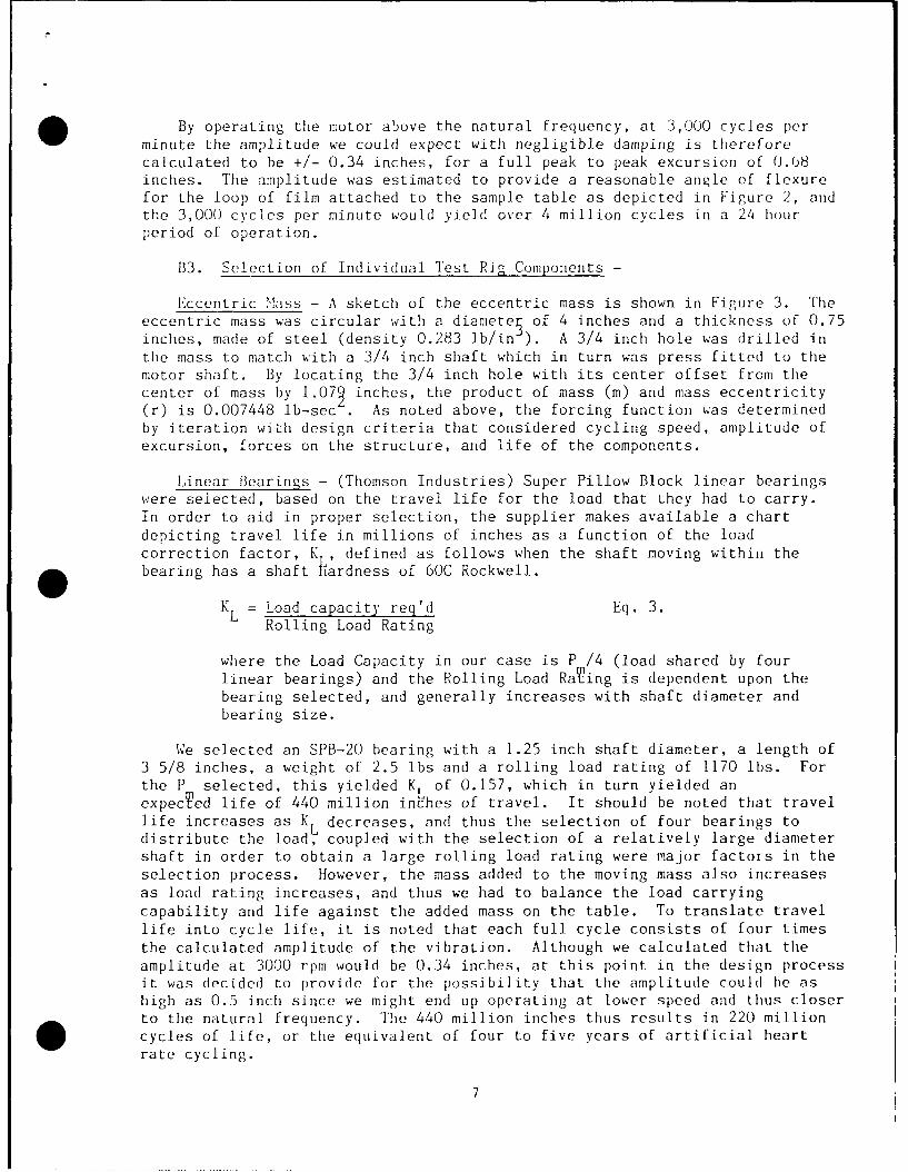
By operating the motor above the natural frequency, at 3,000 cycles perminute the amplitude we could expect with negligible damping is thereforecalculated to be +/- 0.34 inches, for a full peak to peak excursion of 0.08inches. The amplitude was estimated to provide a reasonable angle of flexurefor the loop of film attached to the sample table as depicted in Figure 2, andthe 3,000 cycles per minute would yield over 4 million cycles in a 24 hourperiod of operation.
B3. Selection of Individual Test Pig Components -
Eccentric !ass - A sketch of the eccentric mass is shown in Figure 3. Theeccentric mass was circular with a diamete of 4 inches and a thickness of 0.75inches, made of steel (density 0.283 lb/in ). A 3/4 inch hole was drilled inthe mass to match with a 3/4 inch shaft which in turn was press fitted to themotor shaft. By locating the 3/4 inch hole with its center offset from thecenter of mass by 1.07 inches, the product of mass (M) and mass eccentricity(r) is 0.007448 lb-sec . As noted above, the forcing function was determinedby iteration with design criteria that considered cycling speed, amplitude ofexcursion, forces on the structure, and life of the components.
Linear Bearings - (Thomson Industries) Super Pillow Block linear bearingswere selected, based on the travel life for the load that they had to carry.In order to aid in proper selection, the supplier makes available a chartdepicting travel life in millions of inches as a function of the loadcorrection factor, K , defined as follows when the shaft moving within thebearing has a shaft hardness of 60C Rockwell.
KL = Load capacity req'd Eq. 3.Rolling Load Rating
where the Load Capacity in our case is P /4 (load shared by fourlinear bearings) and the Rolling Load Raring is dependent upon thebearing selected, and generally increases with shaft diameter andbearing size.
We selected an SPB-20 bearing with a 1.25 inch shaft diameter, a length of3 5/8 inches, a weight of 2.5 lbs and a rolling load rating of 1170 lbs. Forthe P selected, this yielded K of 0.157, which in turn yielded anexpecTed life of 440 million inches of travel. It should be noted that travel
life increases as KL decreases, and thus the selection of four bearings todistribute the load, coupled with the selection of a relatively large diametershaft in order to obtain a large rolling load rating were major factors in theselection process. However, the mass added to the moving mass also increasesas load rating increases, and thus we had to balance the load carryingcapability and life against the added mass on the table. To translate travellife into cycle life, it is noted that each full cycle consists of four timesthe calculated amplitude of the vibration. Although we calculated that theamplitude at 3000 rpm would be 0.34 inches, at this point in the design processit was decided to provide for the possibility that the amplitude could be ashigh as 0.5 inch since we might end up operating at lower speed and thus closerto the natural frequency. The 440 million inches thus results in 220 millioncycles of life, or the equivalent of four to five years of artificial heartrate cycling.
7

FLYWEIGHT (STEEL)
D. D
t=.750±.001 X.=.920±_001 D.=.750X =:1.079 D =3.998+ 001
* Figure 3

Needle Bearing Selection - Torringto. model B-128 needle bearings were
selected as the bearings to support the rotating eccentric mass. By using twosuch bearings the load was distributed, and the expected life of the bearingswas extended.
The life factor for the bearings (LF) is given by the manufacturer as afunction of the basic dynamic load capacity (BDC) rating, the load (in thiscase equal to P m/2), and the speed factor (SF) as follows.
LF = BDC/(Load X SF) Eq. 4.
For the bearing selected, the BDC=2020, SF at 3,000 rpm was 3.88, and theP /2 was calculated at 367.5 lbs, yielding LF=1.416. From a manufacturersupplied chart the LF factor predicted 1600 hours of life. At 3000 cycles perminute the life in total cycles is thus 288 million cycles. If the speed hadbeen selected at a higher value, the load would also have been greater,requiring a bearing selection that was longer and/or larger in diameter,features that lead to greater mass of the table.
Motor Selection - In order to select the motor, the operating torque had tobe esti Ated. When the vibrating table has reached a steady state operatingpoint, the motion of the table is such that energy is transferred back andforth between kinetic energy of motion of the table and potential energy ofstored in the springs. The frictional losses in the linear bearings and in theneedle bearings is where the power of the motor is spent.
The torque lost to friction in the needle bearings can be expressed as:
TLOSS =}N.B. Pm RN.B. Eq. 5.
where TLOSS = Torque lost to friction in the needle bearings
/&B. = coefficient of friction for the needle bearings
RN.B. = Pitch Radius of needle bearings, 0.4375 in
and P is defined by Eq. 2.m
For the linear bearings, the force of friction (F ) is in the direction
of motion of vibration, and vibration theory equates the frictional force tothe product of the damping coefficient (c) and the velocity (dx/dt). Thefriction force is also equal to the product of the coefficient of friction forthe linear bearing ( AL B ) and the normal load on the linear bearings whichis sinusoidal and has an afiplitude of Pm (defined by Eq. 2.).
Ff = c(dx/dt) = /--L.B.PmsinC~t Eq. 6.
where the displacement (x) is a sinusoidal function given by:
X = X sinwt Eq. 7.
and where x is the amplitude, W is angular velocity, and t is time.
9

The most convenient form of Eq. 6 is one in which the average force isexpressed as a function of average velocity and average normal load, and wetake for these two averages the root mean square (RNS) values:
(dx/dt) RMS = (xmWj)/T2 Eq. 8.
and (PmsinLt)RiS = Pm/J Eq. 9.
We may now rewrite Eq. 6 in terms of the average force of friction, and wenote that (c) can now be calculated from the manufacturer's value for thecoefficient of friction.:
(Ff)AVG = (c xm W )//= §/L.B. Pm)V "72 Eq. 10.
We must now relate the power delivered by the motor to the frictional powerlosses in the direction of vibration. However, we first note that the motortorque delivered to the eccentric mass is a net torque (TNFT) due to thetorque lost in the needle bearings, and thus the torque developed by the motor,(T MOTOR) can be related to the net torque and torque loss by:
TNET = TMOTOR - TLOSS Eq. 11.
The net power delivered to the eccentric mass, and that is ultimately lost
in the frictional losses in the direction of vibration is then:
POWER = (TNET)(W ) Eq. 12.
The net power lost to friction can also be related to the frictional lossesin the direction of vibration by integrating the frictional force in Eq. 6 withrespect to displacement (x) over a cycle, and dividing by the time for acycle. (This integration thus produces the product of force and distance whichis work or energy, and then by dividing by the time we obtain power.) Theresult of this integration and division by the time per cycle yields:
POWER = (0.5) (c) (x) 2 ( 2 = Eq. 13.m =J (TNET)(WO)E.13
Equations 5, 10, 11, and 13 can now be solved, given the coefficients offriction for the linear bearings and needle bearings, for T f OT0r. Themanufacturer's catalog for the needle bearing gives a coefficient of frictionof 0.0025, and the catalog for the linear bearings gives a coefficient offriction of 0.0027. By using a multiple of 2.5 times these coefficients weintroduced a safety factor into our calculations. The resulting value thuscalculated for T MOTRR was 46 oz-in of torque. The performance curve for themotor selected is shown in Figure 4. The expected efficiency at the operatingpoint was deemed to be an acceptable trade-off compared to the added weightthat would be required had we selected a larger motor.
Spring Selection - The criteria for selection of the springs included: (a)a hole diameter large enough to permit the support rod to pass within, (b)spring constant sufficiently high enough to yield the desired natural frequencyas discussed above, (c) a deflection to free length ratio low enough to permita projection of long life. With these criteria in mind, Danly medium-high loadsprings were selected. These springs are of valve spring quality, are vacuumdegassed and are made of chrome vanadium for long life. Catalog number9-4018-21 were selected with a spring constant equal to 1/4 the equivalent
10

.* . .N
N Z
HTLOl
Li C . . . . . .
0 . . . .. . . . . .. . . U
Ito c 0I
.2 .... .... (0
-4 -Y 0__ __ _
03C0
U)X+ CD 00 . . . . . .. . . . . . . . . C) w w
m - Nu A
I~~~ ~ .)(0 . . . . . Cr) L 00 (L
0 ~ ~~ ~ 0)- wo I 7 N -
(r)- c)0.+'C) ci U u 00) 1-1.I
(0Ln 0 Xn 0I~I IFdnl 0It0 U) 0 I HU. .c

spring constant of 50,880 lb/ft (with the springs preloaded the equivalentspring constant is four times the spring constant of each spring for theconfiguration selected). The free length of these springs is 4.5 inches, andthus the expected deflection of x , including the preload deflection resultedin a small enough ratio of deflecTion to free length to warrant our expectationof long life. These springs could accommodate a shaft diameter of up to 1.5inches, thereby accommodating the selected 1.25 inch shaft diameter.
B.4 Preparation of PBZT Samples -
Most of the effort in preparing PBZT samples focused on the processingtechniques to infiltrate PBZT with polyurethane in an interpenetrating network(IPN). Film samples were also provided to Nu-Tech that consisted of PBZT neat,but since the processing techniques for biaxially oriented film were knownprior to this investigation, the PBZT sample preparation did not constitute amajor portion of the effort. All of the techniques described in this sectionwere performed under subcontract by Foster-Miller, Inc. The text of thissection is reproduced, with only minor editing, from a final report of thesubcontractor's effort, written by Lucy Elandjian of Foster-Miller.
For the polyurethane used in the IPN, Foster-Miller selected a specificpolyurethane, Vibrathane, to demonstrate the microcomposite film approach onthis Phase I program. The selection of this secondary material was an involvedprocess. The candidate materials had to meet certain requirements to qualifyfor this application. These requirements were high flex life (to replicate 40to 50 million heartbeats per year), biocompatibility, low modulus (< 1800 psi)and hardness (<70A Shore Hardness), high elongation (>300 percent) and lowmolecular weight prior to polymerization. Another criterion used for theselection was the availability of the material in the desired prepolymer formwith a molecular weight of 1,000 or less. Due to the nature of PBZT structureand Foster-Miller processing methods, only small polymers can infiltrate insidewhere they are cured (polymerized and cross-linked) in situ with the PBZT film,thus forming a microcomposite.
The materials considered for IPN with PBZT film were polyurethaneureas,polyurethanes and silicones. All of these systems have, to date, been used inthe development of artificial internal organs. The most successful of themhave been the polyurethaneureas. Produced under trade names as "Biomer"(Ethicon Corp.), "Angioflex" (Abiomed, Inc.), "Cardiomat-610" (Contra, Inc.),"TLC-15/TLC-16 and PBS-215M" (Thoratec, Inc., Mercor Div.), polyurethaneureashave low modulus and hardness (< 1800 psi and <70A Shore), and lowhysteresis/creep properties. Their excellent biocompatibility and flexuralproperties make them ideal for blood pump applications.
Polyurethanes, such as "Vibrathane" (Uniroyal Chemical), "Pellethane" (DowChemical) and "Avcothane-51" (Avco Polymers Div.), were the predecessors topolyurethaneureas. They exhibit moderate toughness and modulus, greater than70A Shore hardness, high hysteresis/creep and good flex life. However, thecritical properties (biocompatibility and flex life) are inferior to those ofthe polyurethaneureas; and therefore, their use in artificial devices is nowlimited.
Silicones, such as "Silastic MDX-44210" (Dow Corning) and "Petrarch SS"
(Petrarch System, Inc.) have low flex life, low modulus, moderate toughness andhardness. They lack biocompatibility and thus are no longer used in artificial
12

devices except as part of polyurethane formulations (i.e., Avcothane-51).
Problems of high molecular weight and unavailability of the prepolymer wereencountered while researching the IPN material. The most appropriate materialsfor our application, polyurethaneureas, were originally being sold as ordinaryresins. However, they were taken off the market after the discovery of theirbiocompatibility properties. They are currently being used as proprietarymaterials in the manufacture of medical devices. With the exception ofAngioflex, none of these materials are available in the prepolymer form.
Under the circumstances, polyurethanes were determined to be the mostappropriate material. Their critical properties were close topolyurethaneureas and they were available in low molecular weight,two-component prepolymer form. Thus, Vibrathane B670, a polyurethaneelastomer, was chosen as the secondary IPN material. Vibrathane has amolecular (prepolymer) weight of 750 (cured polymer weight of 100,000) and amodulus of 2,300 psi (low enough, considering TLC-15 is 1,800 psi and Biomer1,400 psi). Although this material is not biocompatible, it is approved forfood contact.
After demonstrating the feasibility of the IPN system and Vibrathane, itmay be possible to draw up an agreement with Abiomed, Inc. and use Angioflex in
future investigations.
PBZT is an aromatic heterocyclic polymer which forms extended chainrigid-rod molecules. it is necessary to process PBZT while in a solution of
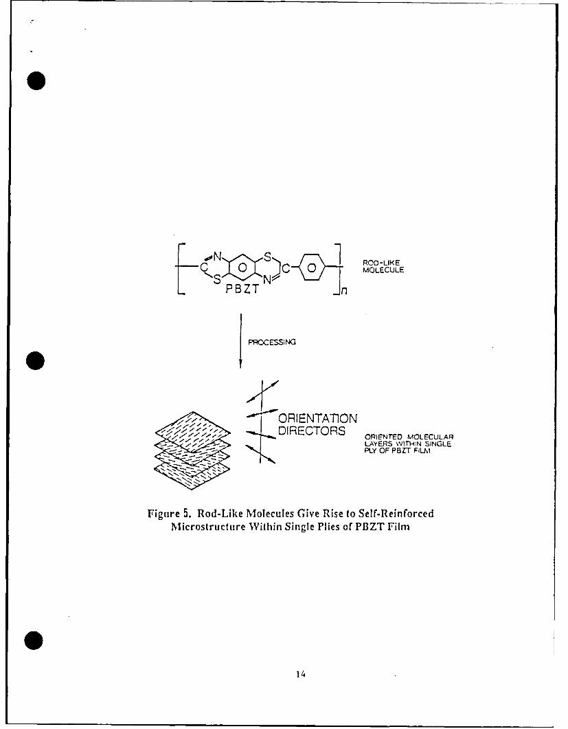
polyphosphoric acid, for it cannot be thermoformed. The stiff rod-likemolecules give rise to a self-reinforced material which has the strength ofadvanced fiber-reinforced composites (Figure 5), but without the drawbacks offiber-matrix mismatch and relatively high interfacial stress. PBZT films werefabricated at Foster-Miller with a proprietary extrusion process capable ofproducing thin, (0.2 mil dry, neat) blown films with controllable microfibrilorientation at + e direction, where 0 is the angle between the fiber and themachine direction. E is tailorable for each desired application (Figure 6).The artificial heart diaphragm requires equal strength in all directions in thefilm plane, and for this isotropic application e = + 45 deg.
Biaxially extruded PBZT blown film was washed in a water bath to removeresidual solvent. The film was then cut into 3-ft lengths and remained in thewater bath until use. The neat PBZT films were dried at elevated temperaturesand pressures to consolidate the microfibrillar structure.
Vibrathane was infiltrated into PBZT films by infusing low molecular weightoligomers into solvent-swollen films prior to drying. We estimate that thespace between bundles of microfibrils, where polyurethane is to infiltrate, isless than 0.1/4. Vibrathanes's molecular weight of 750 was low enough tocomplete infiltration. Water-swollen PBZT films were subjected to a solventexchange process to maintain the open microporous structure while replacing thewater with acetone. The wet tubes were soaked in a 20 percent solution ofpolyurethane in acetone, then dried under controlled stress, making amicrocomposite film of PBZT and polyurethane.
Thick (1.2 mil dry, neat) biaxial + 45 deg films were extruded along withthin films. Thicker film was easier to process at uniform thickness under the
given conditions with existing equipment. It was possible to process thin
13
0I
1 ROO-LIKE
0 MOLECULE
PBZT n
PROCESSING
I[ "ORIENTAT0NDIRECTORS ORINTED MOLECULAR
LAYERS Wf-flSIN GLE"- PLY OF PBZT FIL,
Figure 5. Rod-Like Molecules Give Rise to Self-ReinforcedMicrostructure Within Single Plies of PBZT Film
114

MACHINEtDI RECTION BTFL
Figure 6. PJ3ZT Fibrillar Network Direction
15

biaxial film; however, there was an approximate 20 percent deviation inthickness. The die could be redesigned to maintain uniformity throughout thefilm in subsequent programs. Such a task was not feasible with the Phase Ifunding; nevertheless, the thin films produced to date are adequate for thisstudy, and show promising future performance.
Thick film was also interpenetrated with Vibrathane.
For better control over the experiment, infiltration with a siliconeelastomer was completed. The results of the experiment should provide a gooddatabase for subsequent investigations. The silicone was interpenetrated usingthe same solvent exchange process as the polyurethane, except 30 percentdimethyl dimethoxy silane (molecular weight = 240) was used in the last step.After a 4-hr imbibition period, 20 ml of water and 10 drops hydrochloric acidwere added to the solution to catalyze the formation of a silicone. Figure 7describes the reaction. The PBZT film was allowed to remain in this solutionfor 4 more hours. The film was then dried under the same conditions as thePBZT/polyurethane film.
The following film samples were delivered to Nu-Tech:
a) six (6) sheets of PBZT neat @ 8 in X 36 in X 0.2 mil
b) one (1) sheet of PBZT neat @ 8 in X 20 in X 1.2 mil
c) five (5) sheets of PBZT/Vibrathane @ 8 in X 36 in X 1.3 mil
d) one (1) sheet of PBZT/Vibrathane @ 7 in X 18 in X 3.3 mil
e) one (1) sheet of PBZT/Silicone @ 8 in X 36 in X 0.4 mil.
B.5 Biocompatibility Testing - Nu-Tech conducted biocompatibility tests by
sending samples of PBZT alone and PBZT combined with polyurethane (Vibrathane)in an Interpenetrating Network to the North American Science Associates, Inc.(NAMSA). NAMSA is a biomedical laboratory complex specializing in the
biological safety testing of medical devices. The laboratories are registeredwith the Food and Drug Administration (FDA) and their testing services are usedby numerous companies world wide to satisfy applicable regulations forregulatory agencies including the FDA. For an artificial heart diaphragmmaterial, NAMSA specified four suitable tests for the Phase I effort.
These tests determine not only the fundamental biocompatibility, but are
also capable of identifying substances that can be toxic, yet are introduced inthe fabrication process and that can be subsequently removed.
Two of the tests recommended by NAMSA are classified as qualification tests
and are designed to characterize the material chemically (A USP PhysicoChemical test), and biologically (A Media MMN extract test). In the latter,cell cultures are exposed to an extract of the material, and thus any toxiceffect from potential leachable substances is readily determined. This is oneof the most sensitive cell toxicity tests that can be performed, and thus is anexcellent screening test for new materials.
16

CH3 CH31 H2 0, H( I
CH3 O-Si-OCH3 -- O-Si- OI ICH 3 CH 3
DIMETHYL-DIMETHOXY SILANE DIMETHYLSILICONEPOLYMER
Figure 7. Hydrolysis of DMIDMOS to Silicone Elasforner
S17

The Physicochemical test is a battery of four tests used to characterizeand compare new polymeric materials or to audit materials used in production.The tests provide basic information about the presence and nature ofwater-soluble extractables and residues, particularly those that may causechemical toxicity problems. A 606 sq. cm portion of each of the test materialswas extracted at 70 degrees C for 24 hours in 101 ml of USP Purified Water.Non-volatile reside, residue on ignition, heavy metals as lead and bufferingcapacity were determined in the eluate as outlined below.:
Buffering Capacity - a 20 ml aliquot of sample was titrated to pH 7.0 by0.01 normal acid or base. The result was expressed as the volume in mlrequired to reach pH 7.0. A maximum of 10 ml titrant is allowed.
Heavy Metals as Lead - A color comparison was made between an aliquot ofthe deionized water eluate and an aliquot of a blank containing 1 ppm oflead. The sample passes if the eluate does not contain more than 1 ppm ofmetals as lead.
Non-Volatile Residue - a 50 ml aliquot of the eluate was evaporated todryness and the weight of the residue was determined. The differencesbetween the sample and the blank cannot exceed 15 mg.
Residue on ignition - The residue from the non-volatile residue test wascharred, then ignited in the presence of sulfuric acid at 800 degrees C.The difference between the amounts of residue on ignition was obtained for
0 the sample and blank and cannot exceed 5 mg.
The Cytotoxicity-MEI Elution test or cell culture test is a rapid,economical, in vitro approach to determining biocompatibility of materialintended for use in medical devices. The mammalian cell culture systemsemployed are sensitive and can therefore be utilized in screening programs aswell as in quality control and audit programs. Because of the greatsensitivity of these procedures, results which indicate that a material iscytotoxic must be viewed in conjunction with results of applicable in vivostudies and in light of the intended use of the product. Cell culture modelsrepresent practical, useful in vitro alternatives to animal research.
Four cell lines are used at NAMSA: L-929 mouse fibroblast, WI-38 humanembryonic lung, MRC-5 human embryonic lung, and rabbit corneal cells. TheL-929 cell line was suggested for our tests because it is easiest to culture,the supply is unlimited and it is very dependable. NAMSA has shown excellentagreement among all four cell types tested against materials of low,intermediate and high degrees of cytotoxicity.
A monolayer of L-929 Mouse Fibroblast cells was grownt to confluency andexposed to an extract of the test samples prepared by placing the test articlesin 20 ml of Minimum Essential Medium (Eagle) and bovine serum (5%) andextracting at 37 degrees C for 24 hours. An M aliquot was used as a negativecontrol. A Positive Control was also used that was toxic at a dilution of 1:2at 24 hours. After exposure to the extract, the cells were examinedmicroscopically for cytotoxic effect (CTE). Presence (+) or absence (-) of aconfluent monolayer, intracellular granulation, cellular swelling and crenationand the percentage of cellular lysis were recorded. CTE was scored as eitherNontoxic (N), Intermediate (I) or Toxic(T) as follows:
18

N = Indicates a negative or nontoxic response.
I = Indicates an intermediate response, a subjective assessment of theextent of cellular response.
T = Indicates a positive or toxic response consisting of greater than 50%cell death.
The remaining two tests are in NAISA's category of advancedbiocompatibility tests. An In vitro Hemolysis-Extract test was performed inorder to determine any potential of the materials to cause red blood cell lysisby chemical leachables. This test is typically used in the screening of avariety of biomaterials and polymers intended to contact blood. The secondtest is a Muscle Implantation test to detect macroscopic or microscopic tissuereactions. The tissue reaction is evaluated by a pathologist and compared tothe USP (United States Pharmacopeia) control plastic similarly implanted in thesame test animal.
The In vitro Ilemolysis Extract Test placed a 180 cm portion of each testmaterial in 30 ml of 0.9% sodium chloride solution and extracted at 121 degreesC for I hour. The extract was divided into two tubes of 10 ml each and allowedto cool to room temperature. To each extract and similarly treated controltube was added 0.2 ml of rabbit blood previously collected in a vacuum tubecontaining E.D.T.A. The tubes were inverted gently to mix the contents, thenplaced in a constant temperature water bath at 37 degrees C for 1 hour. Theblood-saline mixture, and positive and negative controls were then centrifugedfor 10 minutes at a speed of not less than 2100 RPM. The absorbence of eachsample solution was determined spectrophotometrically at 545 nm. Similarly,absorbances were recorded for the positive control (10 ml water and 0.2 mlblood) and the negative control (10 ml 0.9% sodium chloride solution and 0.2 mlblood.)
Muscle Implantation Test - Two healthy adult New Zealand White rabbitsweighing not less than 2.5 kg. were used as test animals. The rabbits werehoused individually and allowed food and water ad libitum. Prior to theimplantation, the back of each animal was clipped on both sides of the spinalcolumn. All loose hair was removed after clipping and prior to implantation toprevent entry into the implantation site.
Four strips (minimum) of steam sterilized test material, approximately I mmwide and 10 mm long were introduced into the right paravertebral muscle of eachrabbit. Two strips of U.S.P. negative control plastic were implanted in theleft paravertebral muscle of each rabbit.
The animals were humanely killed 14 days after implantation and the entireparavertebral muscle on each side of the spinal column removed. Cross sectionsof the muscles were made to locate the implants. The tissue surrounding thecenter portion of each implant was examined macroscopically and microscopicallyby a Pathologist for any reaction. Tissues to be examined microscopically werepreserved in 10% Neutral Buffered Formalin, sectioned and stained withHematoxylin and Eosin.
19

B.6 Film Sample Test Preparations and Examination Procedures - In order tocut the film samples from the large sheets supplied by Foster-Miller the sheetswere first examined to determine regions that appeared to be of uniformthickness. The film was laid on a flat, clean and dry surface. The materialwas smoothed out to insure that there were no wrinkles or folds. An exactoknife was used with a new number 11 blade and a steel straight edge was used asa guide. The PBZT materials were cut slightly longer than the controlAngioflex polyurethaneurea films because the mounting procedure consisted ofthe Angioflex material used as a base or underlayment material. A hole punchwas used to make a clean hole in the ends where they were subsequently attachedand clamped to the sample holder of the vibrating table.
On the sample table, five rows or five sample bars each contained ninemounting locations. Nine samples of each of the five PBZT materials wereplaced on the table, and each had its own underlayment of the control Angioflexmatprial. This in tandem mounting with the Angioflex material was necessary,particularly for the thin materials, because of the tendency for staticelectricity to curl the material and interfere with consistent flexuralmotion. The Angioflex material thus provided for a reasonable flexuralconsistency in spite of the differences in thickness of the PBZT materials.However, our observations under a strobe light indicated that the thinnermaterials contained additional nodes of flexure. Our intent, however, was toconcentrate on comparing the point of common flexural motion between the sampletypes; i.e. the region near each clamped end of the samples. In locating fivedifferent materials on the table the order of placement was varied in order toevenly distribute the material types across the five sample bars. In thismanner we sought to eliminate any influence of location on the sample table on
the outcome of the test.
A sample of the Fatigue Test Inspection Sheet is included on the nextpage. Pertinent identification material such as material type, and location ofthe material on the sample table were recorded. The materials were allsubjected to a preliminary examination under 20 power with a stereoscopicmicroscope. Comments were recorded for each sample, and any noteworthy defectswere noted on a drawing of the test sample for future reference. Thispreliminary examination revealed that the PBZT samples of all types typicallyincluded a wrinkled appearance, and numerous regions that seemed to containareas that gave the appearance of "pin holes". Occasionally an edge was foundto have a fuzzy fibrous appearance, and these locations were also noted. Thematerials were not visually homogeneous, and the wrinkled appearance was insharp contrast to the very smooth and homogeneous appearance of the Angioflex.
20

N NU-TECH INDUSTRIES, INC.K31EMDAYTON, OHIO
FATIGUE TEST INSPECTION SHEET
TEST NO - DATE MOTOR/ROTORMATERIAL _ ELECTRONICSLOT NO _ SOFTWARESUPPLIER _ MOTOR SPEEDSAMPLE NO __ SAMPLE LOCATIONCOMMENTS ___ COMMENTS
DATERUN TIME - HRS MINS 0
= CYCLESTYPE
OBSERVATIONS
0
DATERUN TIME - HRS MINS 0. CYCLESTYPE
OBSERVATIONS
0
DATERUN TIME __ HRS - MINS 0CYCLES
STYPEOBSERVATIONS
LAJ
0
DATE _
RUN TIME HRS MINS 0i€ CYCLES _
-TYPE
* OBSERVATIONSC-
0
PAgE 21OF_ Figure 8

*C) RESULTS
C.1. Test Rig Performance Results -
Vibrational Performance - The operation of the vibrational table wasexamined over a speed range near the desired speed of rotation of the motor inorder to determine the relationship between amplitude and vibration. Speed wasmonitored electronically through the motor controller. A piece of thincardboard was clamped to the fixed frame support of the table and allowed tocontact a pen attached to the moving portion of the table. In this manner thelength of the pen marking on the cardboard could be measured to give peak topeak amplitude (i.e 2 x ). Figure 9 is a plot of peak to peak amplitude vsspeed of rotation. Themdata reflects the typical steep rise in amplitude asthe vibrational frequency is increased toward the natural frequency.
By observing the vibrational motion of the table with a strobe light, itwas immediately obvious that the frame also moved with the same vibrationalfrequency, and that we had to take into account that the amplitude as measuredabove was the motion relative to the moving frame. The actual motion relativeto a fixed reference was approximately 80 percent of the amplitude plotted inFigure 9. The motion relative to the fixed reference frame is the trueamplitude of vibration. We also observed that th3 spring motion consisted ofcompression from both ends (i.e. from the table end of each spring, and alsofrom the frame end of each spring). This resulted in a vibrational nodelocated at approximately one coil from the frame end (out of 4.5 coils). Theeffective spring length acting on the tab' ..s thus reduced, and we wouldexpect that the effective spring conc'a .r uu±d in turn be significantlyincreased.
Using Eq. 1, for the '-easured amplitude (relative to a fixed reference) andfor the measured moving mass of 41 iL:' Ii- 2ffective spring constant iscalculated to be 72,719 lb/ft, compared to the spring constant of 50,880 lb/ftthat was expected. This increased value thus correlates with the observationof reduced effective spring length. By using this larger value of springconstant and the measured mass the calculated natural frequency is 2,811 cyclesper minute (compared to the design calculation of 2,444 cycles per minute.Thus, we found that for the operation range plotted in Figure 9 we areoperating below the natural frequency.
By monitoring steady state temperature of the motor, we found thatoperation at approximately 2,400 RPM provided for acceptable motortemperature. For further safety and long term reliability of the motor foursmall fans were placed beside the vibration table, directed at the motor, tomaintain the motor temperature as cool as possible. As the experimentprogressed, and as motor design was altered (discussed below), slight drops inefficiency warranted decreasing the operating speed to as low as 2200 rpm, butobservations of film sample movement indicated that even though amplitude ofmotion of the table was slightly decreased, the actual metion of the filmsamples did not appear to be compromised.
Monitoring the operating torque by comparinp current (luring operation withcurrent-torque characteristics determined by motor characterization tests, thetorque at 2400 RPM was approximately 90 oz-in compared to the 46 oz-in that wehad estimated during the design phase. This meant that operation was at alower efficiency than expected. Higher efficiency at the operating point would
22

0 1
1.2
LJL-
~ 0.9
0.8
€CLaJ 0.7-Cl-
0.6-LJ
_~ 0.5C/')
C) 0.3
0.2
o0 20W0 3000
SPEED (RPM)
Figure 9
23

have permitted faster operation with even greater amplitudes. The cause forthe increased torque is assumed to be additional friction that was notaccounted for. The likely cause of the increased friction was rubbing betweenthe ends of the springs and the brass retainers. Future designs might use sometype of bearing arrangement at this location to cut down on the friction.Friction was high enough at this location to cause fine particles of brass tobe continually eroded.
In conclusion, although we did not anticipate the significant motion of theframe, nor the added friction at the spring retainers, the final result wasacceptable in that 2,400 cycles per minute still resulted in a high rate ofcycling. Furthermore, the amplitude of oscillation was significant as judgedby observation of the motion of the loops of film under a strobe light.
Test Rig Component Life - As with any accelerated life test fixture, thelife of the components would determine the feasibility of using the vibrationtable as an accelerated flex life test rig for film samples. Our experienceover the 104 million cycles of operation that the film samples were subjectedto has been summarized in the time line of Figure 10. Figure 10 has beendivided into three sections with the top two sections devoted to the two majorcomponents, the motor and the springs. The bottom portion of Figure 10 is atime line summary of all problems encountered.
Four different motors were used on the table. Within less than 100,000cycles the first motor failed and we quickly learned that the relatively finecoil wire used in this motor could not withstand the vibration. Each motordesign thereafter used increasingly larger diameter wire for the motorwindings. This resulted in higher current, lower voltage operation, and with asmall decrease in efficiency. However, the results in terms of life of themotor indicated a striking improvement as shown in Figure 10. The second iiotorlasted 9.4 million cycles, the third lasted 38.9 million cycles, and the fourthwas still running at 55.9 million cycles when the experiment was terminated.
The springs were a source of considerable difficulty during the first 10million cycles of operation. Although three springs lasted 8.55 million cyclesand had not broken when they were electively replaced, 5 other springs eachlasted only 4.6 million, 1.5 million, 1.26 million, 0.82 million and 0.17million cycles each during the initial 10 million cycles of operation. Afterthe first spring broke we contacted experts at the supplier company who advisedthat we increase our preloading of the springs from 0.4 inches to 0.5 inches.The reason for this advice was to be sure to avoid any possible "slapping" ofthe springs at the peak excursion point of the table, a situation wherein thesprings may have been completely unloaded and undergoing impact forces. Thissuggestion did not appear to help, since 4 other springs broke thcrcafter. Wewere also advised that in most applications for the springs the maximum numberof cycles to failure was approximately 1 million.
We observed that all but one of these springs failed in the first coildirectly opposite the termination point of the spring. We theorized that thetermination point was impacting on the next coil, creating a stress rise orstress concentration point. In order to eliminate the problem, cup shapedspring retainers were fabricated and the last coil was press fit into thecups. This modification was made on the frame side of each spring, where allof the springs had been failing. All four springs were replaced with newsprings at this point, and three of these springs lasted 95.5 million cycles
24

0(%4
Oo
0-
0
-- o
0
0%F-n
SONINY31 31O33N 0
SONI'V31 NoIow
0
ClCl
SONINY39 vOIOw
____0
-4 -' SC") (VI'Z Clr tL t 4
t25~O~Oa~u'

and were operating properly at the termination of the experiment. One of thesefour springs failed after 52.2 million cycles. This dramatic improvementsuggests that the cup shaped spring retainers had eliminated a stressconcentration and thereby lowered the peak stress below the fatigue limit ofthe material.
Although the motor and springs were the source of most of the difficultymaintaining operation of the table, there were a few miscellaneous problemswith other features of the vibration table. During the first million cycles wefound that the brass spring retainers were rubbing on the support rod shaft,adding too much friction to the operation of the device. These retainers werethen attached to the pillow block on one end, and to the locking mechanism onthe other end in order to permit the shaft to move freely within the retainersNo additional problems were encountered with this design feature.
Motor lead wire failures occurred twice during the first 10 million cyclesdue to vibration. Although the lead wires were selected because of theirmultiple strand nature and subsequent ability to withstand significant flexing,the application at first appeared to be too demanding. However, a procedure ofleading the wires off the table in the direction of motion of the table andthen up to the electronic controller resulted in motion that was moretranslational than flexural, and the problems with lead wires diminished. Thisprocedure was coupled with that of binding the lead wires together to furtherdampen vibratory motion. Thereafter lead wires were replaced with each motorreplacement. It should be noted, though, that had the motors not beenreplaced, it would certainly have been necessary to replace the lead wires.Thus, a recommendation for future work is that of replacing lead wires every 40or 50 million cycles as a maintenance procedure, in addition to taking care toexit the wires in the direction of motion of the table. However, the fact thatthey proved to last 40 to 50 million cycles indicates an acceptable lifetimefor this component.
Additional infrequent problems occurred with motor bearings that needed tobe replaced at the 23 million cycle point and at the 45 million cycle point.Motor speed had decreased indicating the presence of an additional load and thecause for the increased load was traced to the bearings. However, the last setfunctioned for 55.9 million cycles and were operational at the conclusion ofthe experiment. These bearings were not a source of major difficulty, and inthe future could be replaced on a routine basis at 40 or 50 million cycles, andsooner if a drop in speed of operation occurs.
The needle bearings failed twice, indicating that approximately 40 millioncycles could be the limit for this component. However, as with the othermiscellaneous problems cited above, the replacement is not detrimental to theoverall goals of the test fixture and is an readily acceptable maintenanceprocedure.
C2. Film Sample Preparation Results
In addition to preparing films as described in section B, Foster-Millersubjected film samples to a characterization for tensile properties andorientation angle. Except for minor editing, the results in this section areas reported to Nu-Tech by Lucy Elandjian of Foster-Miller in her final report.
26

Table 1 describes the tensile properties of the heart diaphragmsmaterials. The "volume percent of PBZT" refers to the percentage of PBZT inthe whole composite, which includes polymer (especially in the case ofpolyurethane) on the surfaces of the film.
The results of the mechanical tests confirm that the IPN composite fails ina ductile manner with a well-defined yield point and over 7 percent elongationfor thin and over 25 percent for thick PBZT at break. Figure 11 shows thestress-to-strain relationship of a thin and thick neat PBZT, and thin and thickPBZT/Polyurethane composite and a polyurethane film. The IPN composite has thebest of both materials: the high strength of PBZT and the low modulus and highelongation of polyurethane. This combination makes it an ideal high toughnessmaterial for heart diaphragm application. This should be reflected byexcellent fatigue life for the PBZT/polyurethane composite film.
In conclusion, these results prompt Nu-Tech and Foster-Miller to beoptimistic that polyurethane PBZT composite films will be a significantimprovement in the development of artificial heart diaphragms. The goal ofdelivering > 5 year in-service life expectancy is within reach of thiscomposite material as it combines the high tensile strength of PBZT with thetoughness and flexibility of polyurethane.
C3. Biocompatibility Test Results
Physicochemical Tests - The conclusion drawn by NAMSA for Both the PBZT andPBZT IPN materials was that USP limits were met. Specifically, both materialswere found to have identical results as noted below:
PBZT PBZT IPN USP Limits
Non-Volatile Residue 1 mg 1 mg 15 mg
Residue on Ignition < 1 mg K 1 mg 5 mg
Heavy metals < I ppm < 1 ppm 1 ppm
Buffering Capacity < 1 ml < 1 ml 10 ml
Cytotoxicity - MEM Elution - The following identical results were reportedby NAMSA for each of the test samples submitted to this test.
Confluent IntracellularMonolayer Granulation Swelling Crenation % Lysis CTE Score
24 HOURSTest Extract (+) (-) (-) (-) 0 NNegative Control (+) (-) (-) (-) 0 N
48 HOURSTest Extract (+) (-) (-) (-) 0 NNegative Control (+) (-) (-) (-) 0 N
72 HOURSTest Extract (+) (-) (-) (-) 0 NNegative Control (+) (-) (-) (-) 0 N
27

Table I. PBZT Tensile Properties
Thin, IPN Thick, IPNThin, (poly- Thick, (poly- Thin IPNNeat urethane) Neat urethane) (silicone)
Thickness, (in.) 0.0002 0.0013 0.0012 0.0033 0.0004
Volume % ofPBZT 100% 15% 100% 36% 50%
. TensileStrength (ksi) 66 20.2 43.8 20.3 15.2
TensileModulus (Msi) 3.96 0.98 3.92 0.65 1.67
Elongation 1.8% 7.2% 1.1% 25.7% 1.4%
28

0
THIN HEAT PSI
60
THICK HEAT PBT
40
STRESS(kI))
3U
THIN IPh PBT
POLYUR[THAPII
J 0.04 O.Ud O.It 0.1o O.du O.i4 O.Id .J.32
STRAIN
Figurell. Stress-Strain Relationship of PBZT, Polyurethane andPBZT/Polyurethane Composite Materials
29
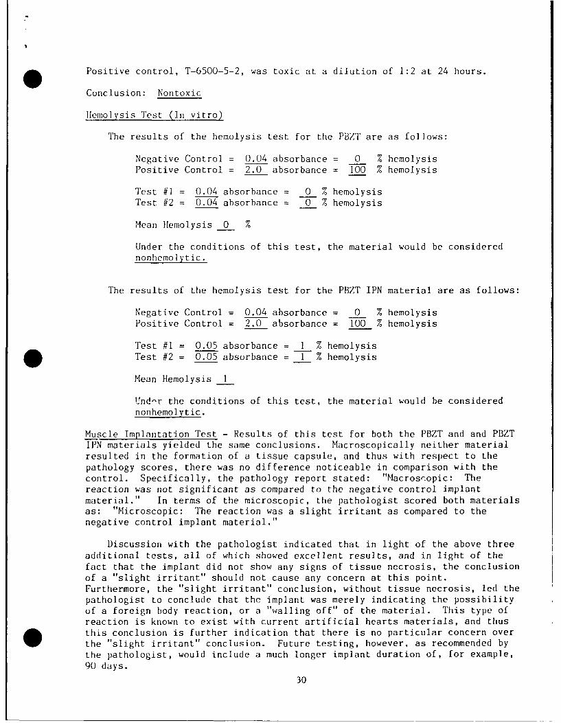
Positive control, T-6500-5-2, was toxic at a dilution of 1:2 at 24 hours.
Conclusion: Nontoxic
Ilemolysis Test (In vitro)
The results of the hemolysis test for the PBZT are as follows:
Negative Control = 0.04 absorbance = 0 % hemolysisPositive Control = 2.0 absorbance = 100 % hemolysis
Test #1 = 0.04 absorbance = 0 % hemolysisTest #2 = 0.04 absorbance = 0 % hemolysis
Mean Ilemolysis 0 %
Under the conditions of this test, the material would be considerednonhemolytic.
The results of the hemolysis test for the PBZT IPN material are as follows:
Negative Control = 0.04 absorbance = 0 % hemolysisPositive Control = 2.0 absorbance = 100 % hemolysis
Test #1 = 0.05 absorbance = 1 % hemolysisTest #2 = 0.05 absorbance = 1 % hemolysis
Mean Hemolysis I
Und-r the conditions of this test, the material would be considered
nonhemolytic.
Muscle Implantation Test - Results of this test for both the PBZT and and PBZT
IPN materials yielded the same conclusions. Macroscopically neither materialresulted in the formation of a tissue capsule, and thus with respect to the
pathology scores, there was no difference noticeable in comparison with the
control. Specifically, the pathology report stated: "Macroscopic: The
reaction was not significant as compared to the negative control implantmaterial." In terms of the microscopic, the pathologist scored both materialsas: "Microscopic: The reaction was a slight irritant as compared to thenegative control implant material."
Discussion with the pathologist indicated that in light of the above three
additional tests, all of which showed excellent results, and in light of thefact that the implant did not show any signs of tissue necrosis, the conclusion
of a "slight irritant" should not cause any concern at this point.
Furthermore, the "slight irritant" conclusion, without tissue necrosis, led the
pathologist to conclude that the implant was merely indicating the possibility
of a foreign body reaction, or a "walling off" of the material. This type ofreaction is known to exist with current artificial hearts materials, and thusthis conclusion is further indication that there is no particular concern over
the "slight irritant" conclusion. Future testing, however, as recommended by
the pathologist, would include a much longer implant duration of, for example,
90 days.
30

As a result of all four tests, and as a result of discussions with thepathologist, we feel that a conclusion that "biocompatible feasibility" hasbeen demonstrated is warranted. This conclusion is drawn while recognizing,however, that more strenuous tests should be performed, such as those relatingto a determination of the potential thrombogenicity of the material.
C4. Film Sample Flexural Fatigue Test Results
Samples were examined at 48.2 million, 87.1 million, and 104.1 millioncycles, under 20 power with a stereomicroscope. The same individual performedall of the examinations so that there would be consistency in the reporting.The observations at 48.2 million and at 104.1 million cycles have beensummarized below in some detail, as a means of presenting the basicinformation. Conclusions that could be drawn are made at the end of thissection.
Observations at 48.2 million cycles
The best means to present summary information for this point in the testwas a general description broken down by sample type.
Thin PBZT/Silicone - This material showed consistent patterns of wear andfatigue. Samples exhibited typically four distinct zones or patterns. Ateach end, slightly above the clamp area, zones of green blotches appear.The surface silicone material gave the appearance of flaking off, leavingfibers coming up out of the parent material. The edges at these sites showsignificant deterioration, with a 'V" shaped wedge of missing materialworking its way inward. The other two zones typically were found on eitherside of the center of the specimen. These zones were found to havenumerous small cracks and many fibers sticking up from the surface givingit a furry appearance.
Thin PBZT - This material was very much like the Thin PBZT/Silicone above.Its zonal characteristics were almost identical. In the opinion of theexaminer, this material seemed to withstand the flexure slightly better asjudged by the number of remarkable features noted.
Thin PBZT/Vibrathane - Overall, this material withstood the cycling flexurevery well. However, there were some areas of fibrous material and in onecase a large section had been torn from the sample, which the examinerattributed to poor sample preparation as opposed to fatigue failure.
Thick PBZT - This material, of comparable thickness to the ThinPBZT/Vibrathane (and thus markedly different in thickness from the firsttwo materials listed above), withstood flexing very well. Typically, theobservation was that fibers were present at the edges, although there wereonly a few fibers coming from the surface.
Thick PBZT/Vibrathane - Similar findings to the Thick PBZT above.
In general, at this point it appeared that the trend was for the thickermaterials to withstand the flexing better. However, since the thin materialsexhibited somewhat more extensive motion (i.e. secondary nodal points ofvibration or flexure), it is possible that the thicker material held up better
31

simply because the fixture did not cause the same degree of motion. The greenappearance could have been caused by lubricants from the bearings leaking downonto the samples. Future testing should utilize a lightweight enclosure toeliminate such an effect and to generally keep the samples cleaner.
Observations at 104.1 million cycles -
A more elaborate recording of the summary information is presented at this,the last observation, in order to provide the reader with a more in depthappreciation of the findings. In the following listing the observations foreach sample have been recorded. At the end of this section trends andconclusions will be discussed.
Thin PBZT -
Sample 1) Many wear holes in the material, specifically at high stressareas and edges. Also at high stress areas there were a great deal of
fibers lifting from the surface.
Sample 2) Wear holes, possible due to rubbing against the Angioflexmaterial. Triangular shaped tears at high stress zone giving theappearance of the MPrerial delaminating.
Sample 3) M-r Lal failed at the clamp. Wear holes present. Reason forfailure is q1.:stionable, however, and could possibly have occurred duringmaintena':e of the vibration table.
Sample 4) Questionable failed sample. Previous inspection had noted ateir forming at one clamp, the same end which tore free. However, thiscould possibly have occurred during maintenance of the table.
Sample 5) Sample missing. Previous inspection had shown a large tearforming at one end with the tear forming from wear holes in the material.This piece had been on a sample block that had fallen off when the supportrod failed.
Sample 6) Sample had an elongated wear hole parallel with the edge,possible due to wear against the Angioflex. Some fibers were found to belifting from the surface and a dark green, almost black zone was found atthe high stress area, but nothing as severe as found on previous samples.
Sample 7) This sample had severe decay of the edge, due possibly from wearwith the Angioflex. The holes parallel with the edge were seen in anearlier inspection, and likely led to the decay and missing segment ofmaterial.
Sample 8) A small piece missing at the edge of the zone of high stresswith elongated holes due to possible wear with the Angioflex. This samplewas not as severely damaged as others.
Sample 9) This sample has a piece missing at the edge in the high stresszone, a series of elongated holes along one side, another triangular tear(with the appearance of delamination) at the stress zone, and two other
zones of green with fibers erupting from the surface.
32

Thin PBZT, general remarks:
This was one of the materials that was so thin that it required theunderlayment material so that it could be tested. The material itself had somuch static electricity that it would stick to itself and so light that itwould not move in a consistent fashion. With the Angioflex as underlayment and
the amount of dirt and debris that the fixture deposited on the samples, theAngioflex could have worked like sandpaper on the PBZT. A consistentobservation was that fibers would erupt from the surface in the areas of highstress, and these fibers were almost certainly due to flexure and not wear.Some tears that occurred at the edges appeared to be a delaminating of thematerial itself, i.e. a tear would start but would peel apart as itpropagated. Wear holes along sides and at high stress points near the clamp
regions appeared to be due more to the wear against the underlayment material.
Thick PBZT -
Sample 1) The only noteworthy change is a few fibers coming out of thesurface. The fibers along the edge were present, to a lesser extent, fromthe start of the testing.
Sample 2) A small tear was found at the clamp, of questionable origin. Afew fibers were found erupting from the surface and along the edge.
Sample 3) Fuzzy, fibrous edges with a few places on the surface wherefibers erupted into ball shapes. There was a zone of green above the clamp
* that had fibers lifting up from the surface.
Sample 4) Fibers found along one edge. A small tear of questionableorigin found on one edge and a fold of material above the clamp that tookon a greenish tinge.
Sample 5) When the sample holder failed due to the failure of the supportrod, the sample was torn. In addition, the edges near a missing segment
were jagged and had a greenish cast to them. Otherwise, the piece did notexhibit any significant signs of deterioration.
Sample 6) Nothing remarkable except for a band of green in a high stressarea and a small hole. The hole appeared to be worn, but the cause wasunknown.
Sample 7) Nothing notable beyond a few fibers at the edge and a couple ofthe surface.
Sample 8) Nothing notable except a few fibers forming circles on thesurface
Sample 9) Fuzzy, fibrous edges, circles with fibers at the center, and a
green spot with some fibers.
Thick PBZT, general remarks:
The deterioration in these samples was primarily exhibited by eruption of
fibers from the surface, although the deterioration was not great in comparisonto the thin materials. While fibrous edges were also noted, these could have
33

caused during the cutting of the samples. The edges looked fractured.
Thin PBZT/Vibrathane -
Sample 1) Except for some fibers at the edge, little deterioration wasexhibited. In fact, small pin holes noted prior to testing did not grow.
Sample 2) Except for light green areas at high stress areas above theclamps, nothing notable.
Sample 3) Some fibers lifting from the surface (noted in previousexamination) and one zone above the clamp in the high stress area that hadnumerous cracks running laterally across the surface.
Sample 4) A small tear in the side of questionable origin and a green zoneabove the clamp in the high stress region.
Sample 5) Other than an elongated piece missing from the previousinspection and a few zones of where the coloration appeared lighter (abovethe clamp areas), the material exhibited little deterioration. The clampon this sample bar failed when the support rod failed, and tore thematerial in two. The piece noted missing originated in a jagged cut regionof the material.
Sample 6) This material was found to be torn in two during the previousinspection. The cause of the tear was unknown, but the sample was verydirty and oily. The area where this occurred was green and jagged inappearance.
Sample 7) Nothing notable except for a dark band above the clamp.
Sample 8) Nothing notable.
Sample 9) Except for a small tear at the side, noted at the 48 millioncycle mark, which did not propagate, there was nothing really notable.
Thin PBZT/Vibrathane, general remarks -
Of the thin materials this appeared to withstand flexure the best, althoughit must be noted that we refer to the material as "thin" to differentiate itfrom another PBZT/Vibrathane material that was 3.3 mil thick. This "Thin"PBZT/Vibrathane was actually 1.3 mil, which was very close in thickness to the"Thick" PBZT material that was 1.2 mil thick. Relatively few fibers were founderupting from the surface.
Thick PBZT/Vibrathane -
Sample 1) Small tear at clamp noted in previous inspection, but the teardid not propagate.
Sample 2) Small tear at clamp noted at the 48 million cycle mark that tore
completely.
Sample 3) Fiber at the edge and a few fibers on the surface.
34
Sample 4) A few fibers in one area, but otherwise nothing remarkable.
Sample 5) A few fibers visible on the edge, otherwise nothing remarkable.
Sample 6) Clamp failure completely removed the center of the material. Afew fibers were noted, but otherwise nothing remarkable.
Sample 7) Nothing remarkable.
Sample 8) A few striations above the clamp, but nothing else remarkableexcept that the sample was found to be particularly dirty.
Sample 9) A few fibers found with circles around them, but nothing elseremarkable except that the sample was found to be particularly dirty.
Thick PBZT/Vibrathane, general remarks -
Other than a few fibers, the damage to the samples appeared to haveoccurred due to failure of the structural components of the vibrating table andsample holder. The material samples appeared to be very durable. However,this material was particularly thick, and therefore may not have moved to thesame degree as other samples.
Thin PBZT/Silicone -
Sample 1) Material appeared to have four high stress zones, apparentlylinked to secondary nodes of vibration. All four showed a great manyfibers coming up from the surface. One of the high stress zones, locatednear the clamp and thus at a region of greatest flexure and possiblygreatest wear against the Vibrathane exhibited numerous holes.
Sample 2) Zones of fibers lifting up, edge wear due to the underlaymentmaterial, small tears with delamination and fibers.
Sample 3) At the previous inspection, a large section was noted to bemissing with a piece of the missing section adhering to the angioflex.Cause suspected to be friction and wear during motion against theVibrathane.
Sample 4) Edge holes forming from wear with Angioflex. Sample was torn bythe sample clamp failure, which also left tears and folds in the material.
Sample 5) Sample clamp failure destroyed this piece also. Material hadcurled up on the c1amp. Deterioration of the sample was difficult todifferentiate between fatigue and damage due to the test rig failure.
Sample 6) Three zones or areas of fibers were found lifting out from thesurface and one of these zones appeared to have many cracks runninglaterally across the material.
Sample 7) One green zone was found at the high stress area that had aS piece missing at the edge and with a hole wearing through. A small tearwas found to be forming at a point where fibers were erupting from thesurface. This also had the appearance of delaminating material.
35

Sample 8) Three zones of green were found with many fibers lifting out ofthe material. One zone above the clamp area had a string of holes acrossthe material that appeared to be due to wear and not flexural fatigue.
Sample 9) Material seemed to be failing from the edges. Green zones withcracks and fibers that resulted in small tears or delamination of thematerial were also observed.
Thin PBZT/Silicone, general remarks -
This material did not withstand the cycling well at all. The mechanics ofits failure appear to be related to zones where cracking is observed, followedby fibers erupting from the surface, with tears and the appearance ofdelamination.
Angioflex -
None of the samples showed any deterioration, except for those damaged bythe sample bar clamp failure. Some of the samples took on a coloration of thePBZT. Otherwise, nothing remarkable was noted.
Fatigue Test Discussion and Conclusions -
The best comparisons between material types are drawn when materials ofsimilar thickness are compared. In comparing the Thin PBZT/Silicone with theThin PBZT the general finding was that neither material withstood the flexing.Eruption of fibers from the surface was the predominant finding, which we feelstrongly was related to fatigue due to the location within the high flexregions. The silicone thus did not appear to improve the basic flexuralcapability of the PBZT. The examiner's conclusion was that if anything, therewas a possibility that the IPN material actually was exhibiting moredeterioration with fatigue than the PBZT neat. However, conclusions areparticularly difficult to draw with these thin materials, because the thinmaterials exhibited far more pin holes with increasing cycle time, which wefeel were likely to be more related to wear than to fatigue.
Perhaps the best comparison between materials was found in comparing theThick PBZT (1.2 mil) with the Thin PBZT/Vibrathane (1.3 mil). The thicknesswas close enough that it was doubtful that thickness would have significantlyinfluenced the results. The primary difference between these materials wasfound in terms of the number of fibers erupting from the surface. The IPNmaterial had only one sample reported with this failure mode, while the ThickPBZT exhibited six of the samples with this feature noted. As noted above, theeruption of fibers in other material samples appeared at times to be associatedwith cracks. After the fibers appeared the material had a tendency to tear ordelaminate from this site. Since the fibers were located in regions of highflexural motion, these observations lead us to conclude that the appearance ofthe fibers was due to flexural fatigue. Because of the observations of farfewer fibers erupting from the surface in the Thin PBZ/Vibrathane material, incomparison with the Thick PBZT material, the results suggest that the processof forming an IPN with Vibrathane improved the basic fatigue properties of thePBZT.
36

Since the Angioflex naterial held up very well, and the PBZT/Vibrathanematerials showed indications of failure, clearly the samples of PBZT/Vibrathanedo no yet have the quality needed to replace the polyurethaneureas. However,when one considers that the processing techniques for the PBZT materials havenot yet been refined to the same degree as the Angioflex material, there isstill a possibility that the PBZT materials would have the potential to beimproved sufficiently. Our observations of the material at Nu-Tech lead us tocomment on what we feel was a striking lack of homogeneity in the materials,from a visual standpoint. We recognize that the structure of the materials,both the PBZT neat and the PBZT IPN is such that homogeneity should exist to afine scale. However, the macroscopic appearance of the materials does notprovide a homogeneous appearance. Furthermore, the eruption of fibers as a keyfeature in the failure mode raises questions also about the homogeneity.Perhaps improvements in processing will eliminate these problems, and if theyare eliminated then we might see the long flex life that we have expected.
The numerous holes found in the thin samples were most likely due to wear.The tendency for friction between these samples and the Angioflex underlaymentmaterial to wear holes in the thin PBZT materials was probably increased by thedirt that adhered to the samples, i.e. there may have been an additionalabrasive substance introduced.
Although the Angioflex material did not fail during the 104 million cyclesof the test, due to the fact that the PBZT materials failed, and failedapparently from fatigue, we conclude that the test fixture provided sufficientflexural stress to warrant continuing investigations into its use as a flexuralfatigue tester. Although the test rig design as it existed at the end of theexperiment provided adequate test time between component failures and/ormaintenance to justify its use as an accelerated life test fixture, thepotential for improvements discussed in the next section could make the deviceeven more attractive.
D) RECOMMENDATIONS FOR FUTURE WORK
The accelerated life test fixture, in its final form at the end of thisdevelopment, provided a means to obtain flexural testing within a couple ofmonths as opposed to years of real time testing. However, we have identifiedseveral areas of improvement in future designs.
Excessive friction on the table that could most likely be reduced would beat the location where the springs contact a brass retainer. Friction was foundto be high enough to continually produce brass particles. Some type of bearingarrangement at the contact between springs and the retainer might reduce thefriction considerably. This reduction in friction would impact the overalldesign in a favorable fashion from the standpoint of requiring less motortorque. This would in turn permit the table to be operated at largeramplitudes and/or higher rates.
In the next design it would be appropriate to expend some design effort ona lightweight enclosure for the test samples. The present design exposed thesamples to dirt and lubrication that was shed from the bearings.
Yet another design change that could be worth exploring would be the use ofa flexible drive cable, thereby permitting the motor and its mass to be removed
from the table. Although the final motor design used in this study performed
37

remarkably well in the face of significant vibration, removal of mass from thetable would improve performance considerably. The drive cable would have to bebrought off the table in the direction of motion of the table, much like thelead wires to the motor were brought off the table in the present design, inorder to minimize flexing of the cable.
In terms of testing the materials, we would recommend confining the testingto materials of the same thickness. Experimentation with varying lengths ofthe samples could prove to be desirable as a means to increase the motion. Useof the Angioflex material as an underlayment appeared to be a good method offorcing the PBZT materials to move in a consistent fashion, and has anadvantage of providing a control for comparison for each PBZT sample. Thedisadvantage was the wear exhibited by the thin samples, and thus we wouldrecommend that the samples be at least I mil in thickness.
An investigation from a materials processing standpoint appears warrantedin order to determine the nature of the fibers that were found to erupt fromthe materials surface as the fatigue failure mechanism. If the materialprocessing can be improved, there is a significant opportunity to provide ahigh flex life material from the PBZT. Furthermore, if the prepolymer of apolyurethaneurea could be obtained instead of the Vibrathane, results mightsignificantly improve.
Biocompatibility testing should include longer duration muscle implantationtesting to assure that there are no long term toxic effects. Furthermore,testing with respect to the potential for the material to be thrombogenicshould be pursued as part of the next level of biocompatibility testing.
Perhaps the best potential for ordered polymer films to provide a high flexlife material for biomedical applications comes from other ordered polymers inthe same family. Nu-Tech Industries is aware that private industry is workingon such a material that would be more flexible than the PBZT materials testedin this study. Ordered polymers of the family used in this study may hold thekey to high flex life materials for biomedical and aerospace applications.
E. LITERATURE CITED
1) Request for Proposal No. NHLBI-HV-86-02, Development of Implantable CardiacBiventricular Assist and Replacement Devices. National Institutes ofHealth, National Heart, Lung and Blood Institute, January 15, 1986.
2) Dew PA, Olsen DB, Kessler TR, Coleman DL, and Kolff WJ. MechanicalFailures in In vivo and In vitro Studies of Pneumatic Total ArtificialHearts. Trans Am Soc Artif Intern Organs. 30:112-116, 1984.
38