wrinkling of tympanic membrane under unbalanced pressure
TRANSCRIPT
Bo WangSchool of Mechanical and
Aerospace Engineering,
Oklahoma State University,
Stillwater, OK 74078
e-mail: [email protected]
Pravarsha GhantaSchool of Mechanical and
Aerospace Engineering,
Oklahoma State University,
Stillwater, OK 74078
e-mail: [email protected]
Sandra VinnikovaSchool of Mechanical and
Aerospace Engineering,
Oklahoma State University,
Stillwater, OK 74078
e-mail: [email protected]
Siyuan BaoSchool of Civil Engineering,
University of Science and
Technology of Suzhou,
Suzhou 215011, China;
School of Mechanical and
Aerospace Engineering,
Oklahoma State University,
Stillwater, OK 74078
e-mail: [email protected]
Junfeng LiangDepartment of Electrical Engineering,
The University of Texas at Dallas,
Richardson, TX 75080
e-mail: [email protected]
Hongbing LuDepartment of Electrical Engineering,
The University of Texas at Dallas,
Richardson, TX 75080
e-mail: [email protected]
Shuodao Wang1
School of Mechanical and
Aerospace Engineering,
Oklahoma State University,
Stillwater, OK 74078
e-mail: [email protected]
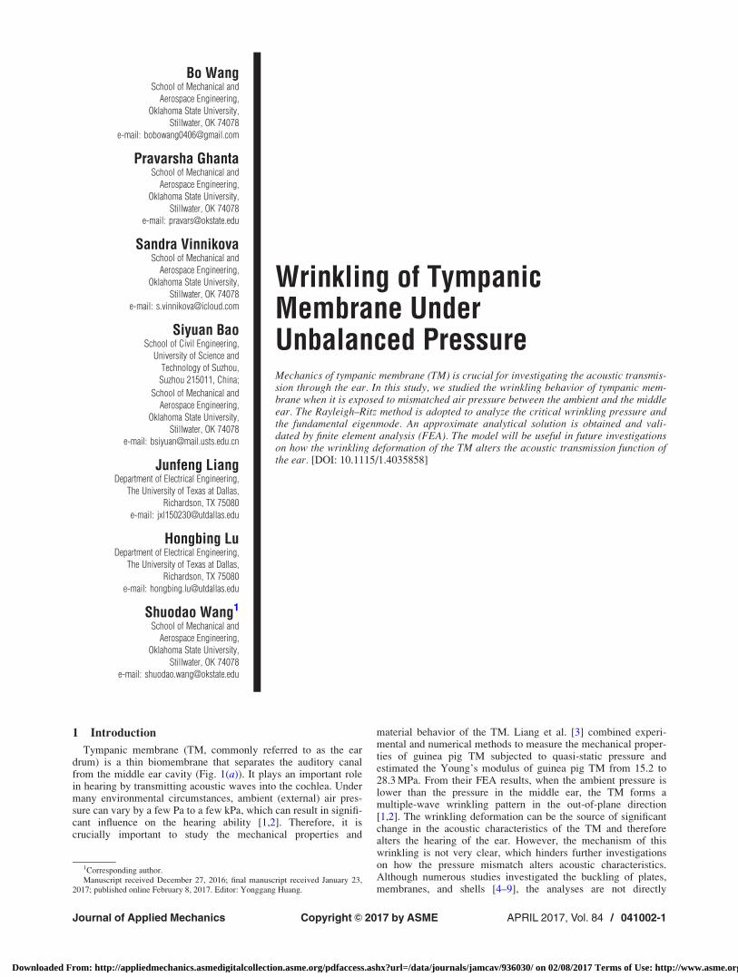
Wrinkling of TympanicMembrane UnderUnbalanced PressureMechanics of tympanic membrane (TM) is crucial for investigating the acoustic transmis-sion through the ear. In this study, we studied the wrinkling behavior of tympanic mem-brane when it is exposed to mismatched air pressure between the ambient and the middleear. The Rayleigh–Ritz method is adopted to analyze the critical wrinkling pressure andthe fundamental eigenmode. An approximate analytical solution is obtained and vali-dated by finite element analysis (FEA). The model will be useful in future investigationson how the wrinkling deformation of the TM alters the acoustic transmission function ofthe ear. [DOI: 10.1115/1.4035858]
1 Introduction
Tympanic membrane (TM, commonly referred to as the eardrum) is a thin biomembrane that separates the auditory canalfrom the middle ear cavity (Fig. 1(a)). It plays an important rolein hearing by transmitting acoustic waves into the cochlea. Undermany environmental circumstances, ambient (external) air pres-sure can vary by a few Pa to a few kPa, which can result in signifi-cant influence on the hearing ability [1,2]. Therefore, it iscrucially important to study the mechanical properties and
material behavior of the TM. Liang et al. [3] combined experi-mental and numerical methods to measure the mechanical proper-ties of guinea pig TM subjected to quasi-static pressure andestimated the Young’s modulus of guinea pig TM from 15.2 to28.3 MPa. From their FEA results, when the ambient pressure islower than the pressure in the middle ear, the TM forms amultiple-wave wrinkling pattern in the out-of-plane direction[1,2]. The wrinkling deformation can be the source of significantchange in the acoustic characteristics of the TM and thereforealters the hearing of the ear. However, the mechanism of thiswrinkling is not very clear, which hinders further investigationson how the pressure mismatch alters acoustic characteristics.Although numerous studies investigated the buckling of plates,membranes, and shells [4–9], the analyses are not directly
1Corresponding author.Manuscript received December 27, 2016; final manuscript received January 23,
2017; published online February 8, 2017. Editor: Yonggang Huang.
Journal of Applied Mechanics APRIL 2017, Vol. 84 / 041002-1Copyright VC 2017 by ASME
Downloaded From: http://appliedmechanics.asmedigitalcollection.asme.org/pdfaccess.ashx?url=/data/journals/jamcav/936030/ on 02/08/2017 Terms of Use: http://www.asme.org/about-asme/terms-of-use
applicable to the buckling of soft biomembranes here. For exam-ple, Sharghi et al. [4] used an analytical approach to investigatethe buckling of truncated conical shells made of composite mate-rials with general lamination sequence. Dung et al. [5] studied thebuckling of an eccentrically stiffened sandwich truncated conicalshell subjected to an axial compressive load and uniform pressure.Anh et al. [7] investigated the nonlinear stability of thin function-ally graded material annular spherical shell on elastic foundationssubjected to external pressure and thermal loads. Sofiyev andKuruoglu [9] used the large deformation theory and vonKarman–Donnell-type of kinematic nonlinearity to study thebuckling of truncated conical composite shell surrounded by anelastic medium. Most of these studies focused on macroscopicstructures with composite materials and are not readily applicableto soft biomembranes such as the TM here. In this study, based onthe von Karman–Donnell type of kinematic and nonlinear shelltheory, an analytical model is developed for the wrinkling of theTM. The results are validated by FEA, which will inform futurestudies on acoustic characteristics.
2 Mechanics Model
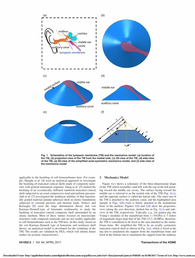
Figure 1(c) shows a schematic of the three-dimensional shapeof the TM which resembles sand hill with the top of the hill point-ing toward the middle ear cavity. The surface facing toward themiddle ear is referred to as the medial side of the TM (Fig. 1(c)),and the opposite surface is called the lateral side. The outer rim ofthe TM is attached to the auditory canal, and the highlighted area(purple in Figs. 1(b)–1(d)) is firmly attached to the manubriumbone of the malleus. Figures 1(b) and 1(d) show the projection-view (along the axis direction, dashed line in Fig. 1(c)) and side-view of the TM, respectively. Typically, e.g., for guinea pig, theYoung’s modulus of the manubrium bone (�10 GPa) is 3 ordersof magnitude larger than that of the TM (15.3–28 MPa); therefore,the TM is considered to be fixed in the area attached to the manu-brium bone. We simplified the TM to be an axially symmetrictruncated conical shell as shown in Fig. 1(e), which is fixed at thetop rim to simulation the support from the manubrium bone andfixed at the bottom rim to simulation the support from the auditory
Fig. 1 Schematics of the tympanic membrane (TM) and the mechanics model: (a) location ofthe TM, (b) projection-view of the TM from the medial side, (c) 3D-view of the TM, (d) side-viewof the TM, (e) 3D-view of the simplified axial-symmetric mechanics model, and (f) side-view ofthe mechanics model
041002-2 / Vol. 84, APRIL 2017 Transactions of the ASME
Downloaded From: http://appliedmechanics.asmedigitalcollection.asme.org/pdfaccess.ashx?url=/data/journals/jamcav/936030/ on 02/08/2017 Terms of Use: http://www.asme.org/about-asme/terms-of-use
canal. The coordinates are shown in Fig. 1(f): S is the distancefrom the vertex along a generator; h is the angle in the circum-ferential direction; u and v (not shown in the figures) denotethe displacement along the S and h directions, respectively, andw is the displacement perpendicular to the membrane surface(Fig. 1(f)). Geometric parameters of the truncated conical shellinclude c—the semivertical angle, S1 and S2—the distancesfrom the vertex to the top and bottom rims, respectively. Whenthe ambient (external) pressure is lower than the pressure in themiddle ear cavity (negative pressure), a uniform pressure p isapplied on the medial side of the TM, acting against the surfacenormal (Fig. 1(f)).
When the conical shell deforms, we assume the following kine-matically admissible displacement field which is adopted in previ-ous stability analysis of conical shell [10]
u ¼ A cosp S� S1ð ÞS2 � S1
� �cos khð Þ
v ¼ B sinp S� S1ð ÞS2 � S1
� �sin khð Þ
w ¼ C sinp S� S1ð ÞS2 � S1
� �cos khð Þ
8>>>>>>>>>>>><>>>>>>>>>>>>:
(1)
where A, B, and C are the buckling amplitudes to be determined,and k is wave number. This displacement field satisfies the bound-ary condition of u¼ v¼w¼ 0 at S¼ S1 and at S¼ S2 and alsodescribes k wrinkling waves in a circumference.
The strain–displacement relations at the middle surface of adeformed truncated conical shell are given by [11]
eS ¼@u
@S
eh ¼1
S sin c@v
@hþ u
S� w
Scot c
eSh ¼1
S sin c@u
@h� v
Sþ @v
@S
8>>>>>>>>><>>>>>>>>>:
(2)
in which the membrane strains are assumed to be small at theonset of wrinkling, and therefore only the leading-order terms areconsidered. The bending curvatures are [11]
vS ¼ �@2w
@S2
vh ¼ �1
S
@w
@S� 1
S2 sin2c
@2w
@h2
vSh ¼1
S2 sin c@w
@h� 1
S sin c@2w
@S@h
8>>>>>>>>><>>>>>>>>>:
(3)
where finite rotation of the shell is taken into account by consider-ing the second-order terms.
The unbalanced pressure loading is considered to be quasi-static (as is in the corresponding experiments of Liang et al. [3]);therefore, the transient response of the TM due to viscoelasticityis not considered in this study. Experiments also found that theTM is linear elastic for strains up to �10% [3]; therefore, materialnonlinearity is not considered when analyzing the small deforma-tion at initial wrinkling. However, for future studies on post-buckling of the TM under auditory high frequency range, afrequency-dependent viscoelastic–hyperelastic model should betaken into account. The strain energy of the structure consists ofthe membrane energy Um and the bending energy Ubend. Themembrane and bending energies are given as [10]
Um ¼Eh
2 1� �2ð Þ
ð2p
0
ðS2
S1
e2S þ 2�ehes þ e2
h þ1� �
2� e2
Sh
� �� S sin cð ÞdSdh (4)
and
Ubend ¼Eh3
24 1� �2ð Þ
ð2p
0
ðS2
S1
v2Sþ 2�vhvs þ v2
hþ1� �
2� v2
Sh
� �� S sin cð ÞdSdh (5)
where E and � are the Young’s modulus and Poisson’s ratio of themembrane, respectively, and h is the thickness of the TM.
Following the approach developed by Baruch and Singer [11],Steyer and Zien [12] and Kendrick [13–15] for hydrostaticallyloaded conical shells, the work by the external load p is calculatedas (see the Appendix for details) [11]
Wp ¼p
2tan c
ð2p
0
ðS2
S1
S2 sin c2
@w
@S
� �2
þ 1
sin c@w
@h
� �2" #
dSdh (6)
The total potential energy of the system is obtained by
P ¼ Um þ Ubend �Wp (7)
Minimizing the total potential energy P with respect to theamplitudes A, B, and C, i.e.,
@P@A¼ 0
@P@B¼ 0
@P@C¼ 0
8>>>>>>>>><>>>>>>>>>:
(8)
yields
e11 e12 e13
e12 e22 e23
e13 e23 e33
266664
377775
A
B
C
266664
377775 ¼ 0 (9)
where eij (i, j¼ 1, 2, 3) are analytical functions (given in theAppendix, eij¼ eji) depending on the nondimensional parametersc, S2/S1, S2/h, k, and p/E. Nonzero solution exists for Eq. (9) onlywhen the determinant of the [eij] matrix equals zero, i.e., det(eij)¼ 0 which yields the critical pressure pcr as
pcr ¼ E � f c;S2
S1
;S2
h; �; k
� �(10)
where f is a nondimensional function determined from det(eij)¼ 0. The wave number kmin corresponds to the lowest criticalpcr_min can be obtained by solving
@pcr
@k¼ 0 (11)
and then rounding to the nearest smaller/larger integer.
3 Results and Discussion
For the TM of the guinea pig [3], the Young’s modulus is takenas E¼ 25 MPa, the Poisson’s ratio is �¼ 0.20, and the thickness ish¼ 10 lm. The shape of a typical TM is characterized by
Journal of Applied Mechanics APRIL 2017, Vol. 84 / 041002-3
Downloaded From: http://appliedmechanics.asmedigitalcollection.asme.org/pdfaccess.ashx?url=/data/journals/jamcav/936030/ on 02/08/2017 Terms of Use: http://www.asme.org/about-asme/terms-of-use
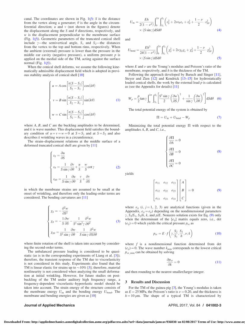
c¼ 55.4 deg, S2¼ 3.04 mm, and S1¼ 1.25 mm. Using theseparameters, Eq. (11) gives k¼ 8.47, then the pcr at k¼ 8 and k¼ 9are compared. It was found that k¼ 9 corresponds to the minimumpcr¼ 30.5 Pa. These values agree very well with FEA (linear per-turbation analysis with shell elements, based the above data, toextract the buckling deformation mode and the corresponding crit-ical pressure) that yields k¼ 9 and pcr¼ 30.9 Pa. The wrinkledshape from the FEA (Fig. 2(a)) also agrees reasonably well withexperimental and post-buckling FEA images obtained byLiang et al. [3].
FEA was also used to validate the assumption of simplifiedaxial-symmetric shape. Figure 2(b) shows an FEA model thataccounts for the exact shape of the TM and the manubrium bone,which yields similar wrinkling pressure (pcr¼ 29.4 Pa, comparableto the 30.5 Pa by the analytical model) and patterns (the period ofthe wrinkling waves is 36.4 deg, compared to 40 deg by the analyt-ical model). These results confirm that the effect of the manu-brium bone on the critical pressure and the wrinkling shape isrelatively small.
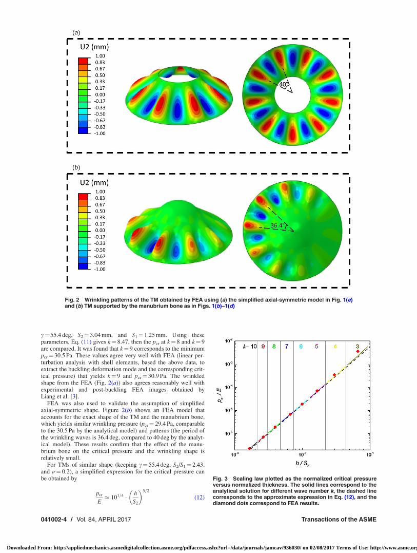
For TMs of similar shape (keeping c¼ 55.4 deg, S2/S1¼ 2.43,and �¼ 0.2), a simplified expression for the critical pressure canbe obtained by
pcr
E� 101=4 � h
S2
� �5=2
(12)
Fig. 2 Wrinkling patterns of the TM obtained by FEA using (a) the simplified axial-symmetric model in Fig. 1(e)and (b) TM supported by the manubrium bone as in Figs. 1(b)–1(d)
Fig. 3 Scaling law plotted as the normalized critical pressureversus normalized thickness. The solid lines correspond to theanalytical solution for different wave number k, the dashed linecorresponds to the approximate expression in Eq. (12), and thediamond dots correspond to FEA results.
041002-4 / Vol. 84, APRIL 2017 Transactions of the ASME
Downloaded From: http://appliedmechanics.asmedigitalcollection.asme.org/pdfaccess.ashx?url=/data/journals/jamcav/936030/ on 02/08/2017 Terms of Use: http://www.asme.org/about-asme/terms-of-use
which is a very useful scaling law for in vivo measurement of themechanical properties of the TM [3]. Equation (12) is plotted inFig. 3, which shows very nice agreements between the analyticalmodel, the approximate expression, and FEA.
4 Conclusions
In this paper, an analytical model is established for the wrin-kling of a soft biomembrane (the TM) undergoing mismatch pres-sure between the middle and external ear. The critical wrinklingpressure and the wave number are obtained analytically, whichagree very well with FEA and experimental observations. It wasfound that the support from the manubrium bone has small effecton the critical wrinkling pressure and the wrinkling shape. Theanalytical model established here provides a useful tool for futurestudies on the mechanics of TM such as in vivo mechanical prop-erty measurements and effects of pressure on the acoustic trans-mission function of the eardrum.
Acknowledgment
S. Wang acknowledges the support from the ASME AppliedMechanics Division—Haythornthwaite Foundation Research Ini-tiation Grant. H. Lu acknowledges Louis A. Beecherl Jr. Chair.
S. Wang acknowledges partial support from the National Natu-ral Science Foundation of China (NSFC) (Nos. 11272260,11172022, 11572022, 51075327, and 11302038). H. Lu acknowl-edges the support of Department of Defense of the United States(DOD) (W81XWH-13-MOMJPC5-IPPEHA, W81XWH-14-1-0228), National Institutes of Health (NIH) (R01DC011585),National Science Foundation (NSF) (CMMI-1636306, ECCS-1307997), and Air Force Office of Scientific Research (AFOSR)(FA9550-14-1-0227).
Appendix
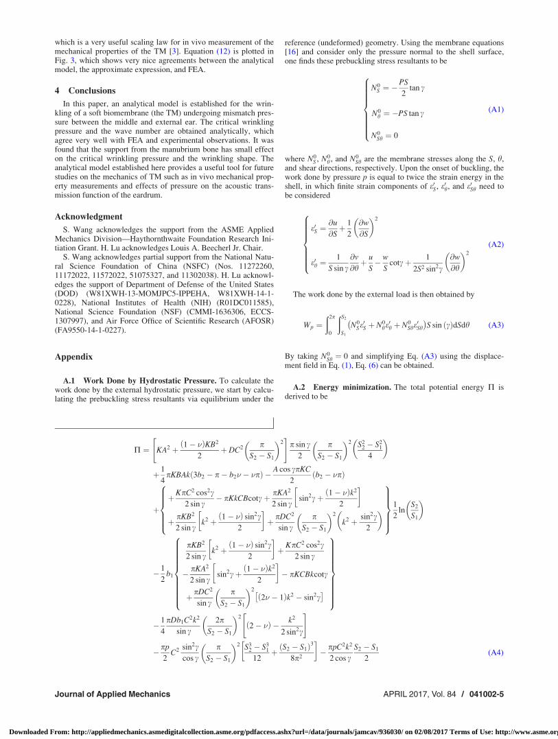
A.1 Work Done by Hydrostatic Pressure. To calculate thework done by the external hydrostatic pressure, we start by calcu-lating the prebuckling stress resultants via equilibrium under the
reference (undeformed) geometry. Using the membrane equations[16] and consider only the pressure normal to the shell surface,one finds these prebuckling stress resultants to be
N0S ¼ �
PS
2tan c
N0h ¼ �PS tan c
N0Sh ¼ 0
8>>>>>>><>>>>>>>:
(A1)
where N0S , N0
h , and N0Sh are the membrane stresses along the S, h,
and shear directions, respectively. Upon the onset of buckling, thework done by pressure p is equal to twice the strain energy in theshell, in which finite strain components of e0S, e0h, and e0Sh need tobe considered
e0S ¼@u
@Sþ 1
2
@w
@S
� �2
e0h ¼1
S sin c@v
@hþ u
S� w
Scotcþ 1
2S2 sin2c
@w
@h
� �2
8>>>>>><>>>>>>:
(A2)
The work done by the external load is then obtained by
Wp ¼ð2p
0
ðS2
S1
N0Se0S þ N0
he0h þ N0
She0Sh
� �S sin ðcÞdSdh (A3)
By taking N0Sh ¼ 0 and simplifying Eq. (A3) using the displace-
ment field in Eq. (1), Eq. (6) can be obtained.
A.2 Energy minimization. The total potential energy P isderived to be
P ¼ KA2 þ 1� �ð ÞKB2
2þ DC2 p
S2 � S1
� �2" #
p sin c2
pS2 � S1
� �2 S22 � S2
1
4
� �
þ 1
4pKBAk 3b2 � p� b2� � �pð Þ � A cos cpKC
2b2 � �pð Þ
þþKpC2 cos2c
2 sin c� pKkCBcotcþ pKA2
2 sin csin2cþ 1� �ð Þk2
2
� �
þ pKB2
2 sin ck2 þ 1� �ð Þ sin2c
2
� �þ pDC2
sin cp
S2 � S1
� �2
k2 þ sin2c2
� �8>>>><>>>>:
9>>>>=>>>>;
1
2ln
S2
S1
� �
� 1
2b1
pKB2
2 sin ck2 þ 1� �ð Þ sin2c
2
� �þ KpC2 cos2c
2 sin c
� pKA2
2 sin csin2cþ 1� �ð Þk2
2
� �� pKCBkcotc
þ pDC2
sin cp
S2 � S1
� �2
2� � 1ð Þk2 � sin2c�
8>>>>>>>>><>>>>>>>>>:
9>>>>>>>>>=>>>>>>>>>;
� 1
4
pDb1C2k2
sin c2p
S2 � S1
� �2
2� �ð Þ � k2
2 sin2c
" #
� pp
2C2 sin2c
cos cp
S2 � S1
� �2 S32 � S3
1
12þ S2 � S1ð Þ3
8p2
� �� ppC2k2
2 cos cS2 � S1
2(A4)
Journal of Applied Mechanics APRIL 2017, Vol. 84 / 041002-5
Downloaded From: http://appliedmechanics.asmedigitalcollection.asme.org/pdfaccess.ashx?url=/data/journals/jamcav/936030/ on 02/08/2017 Terms of Use: http://www.asme.org/about-asme/terms-of-use
where b1 ¼Ð S2
S11=S cos 2p S� S1ð Þ=S2 � S1½ �dS, b2 ¼
Ð S2
S11=Ssin
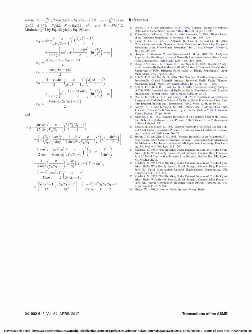
2p S� S1ð Þ=S2 � S1½ �dS, K ¼ Eh= 1� �2ð Þ, and D ¼ Kh2=12.Minimizing P by Eq. (8) yields Eq. (9), and
e11 ¼ sin cp
S2=S1 � 1
� �2 S22=S2
1 � 1
4
� �
þ 1
2 sin csin2cþ 1� �ð Þk2
2
� �ln
S2
S1
� �þ b1
� �
e12 ¼k 3b2 � p� b2� � �pð Þ
4
e13 ¼ �cos c b2 � �pð Þ
2
e22 ¼1� �ð Þsin c
2
pS2=S1 � 1
� �2 S22=S2
1 � 1
4
� �
þ 1
2 sin ck2 þ 1� �ð Þ sin2c
2
� �ln
S2
S1
� �� b1
� �
e23 ¼ �kcotc ln S2=S1ð Þ � b1½ �
2
and
e33¼sinc12
h2
S21
pS2=S1�1
� �4 S22=S2
1�1
4
� �
þ1
2ln
S2
S1
� �cos2csinc
þ 1
6sinch2
S21
pS2=S1�1
� �2
k2þ sin2c2
� �" #
�b1 cos2c2sinc
� b1k2
6sinch2
S21
pS2=S1�1
� �2
2��� k2
2sin2c
!
� 1
3sincp
S2=S1�1
� �2
b1
h2
S21
2��1ð Þk2� sin2c�
� 1��2ð Þpsin2cEcosc
S1
h
pS2=S1�1
� �2
� S32=S3
1�1
12þ S2=S1�1ð Þ3
8p2
� �� 1��2ð Þpk2
EcoscS1
h
S2=S1�1
2
References
[1] Dirckx, J. J. J., and Decraemer, W. F., 1991, “Human Tympanic MembraneDeformation Under Static Pressure,” Hear. Res., 51(1), pp. 93–105.
[2] Volandri, G., Di Puccio, F., Forte, P., and Carmignani, C., 2011, “Biomechanicsof the Tympanic Membrane,” J. Biomech., 44(7), pp. 1219–1236.
[3] Liang, J., Fu, B., Luo, H., Nakmali, D., Gan, R. Z., and Lu, H., 2015,“Characterisation of the Nonlinear Elastic Behaviour of Guinea Pig TympanicMembrane Using Micro-Fringe Projection,” Int. J. Exp. Comput. Biomech.,3(4), pp. 319–344.
[4] Sharghi, H., Shakouri, M., and Kouchakzadeh, M. A., 2016, “An AnalyticalApproach for Buckling Analysis of Generally Laminated Conical Shells UnderAxial Compression,” Acta Mech., 227(4), pp. 1181–1198.
[5] Dung, D. V., Hoa, L. K., Thuyet, B. T., and Nga, N. T., 2016, “Buckling Analy-sis of Functionally Graded Material (FGM) Sandwich Truncated Conical ShellsReinforced by FGM Stiffeners Filled Inside by Elastic Foundations,” Appl.Math. Mech., 37(7), pp. 879–902.
[6] Anh, V. T. T., and Duc, N. D., 2016, “The Nonlinear Stability of AxisymmetricFunctionally Graded Material Annular Spherical Shells Under Thermo-Mechanical Load,” Mech. Adv. Mater. Struct., 23(12), pp. 1421–1429.
[7] Anh, V. T. T., Bich, D. H., and Duc, N. D., 2015, “Nonlinear Stability Analysisof Thin FGM Annular Spherical Shells on Elastic Foundations Under ExternalPressure and Thermal Loads,” Eur. J. Mech. A, 50, pp. 28–38.
[8] Duc, N. D., Anh, V. T. T., and Cong, P. H., 2014, “Nonlinear AxisymmetricResponse of FGM Shallow Spherical Shells on Elastic Foundations Under Uni-form External Pressure and Temperature,” Eur. J. Mech. A, 45, pp. 80–89.
[9] Sofiyev, A. H., and Kuruoglu, N., 2013, “Non-Linear Buckling of an FGMTruncated Conical Shell Surrounded by an Elastic Medium,” Int. J. PressureVessels Piping, 107, pp. 38–49.
[10] Manning, S. D., 1969, “General Instability of a Cylindrical Shell With ConicalEnds Subject to Uniform External Pressure,” Ph.D. thesis, Texas TechnologicalCollege, Lubbock, TX.
[11] Baruch, M., and Singer, J., 1963, “General Instability of Stiffened Circular Con-ical Shell Under Hydrostatic Pressure,” Technion Isroel Institute of Technol-ogy, Haifa, Israel, TAE Report No. 28.
[12] Steyer, C. C., and Zien, S.-C., 1961, “General Instability of an Orthotropic Cir-cular Conical Shell Under Hydrostatic Pressure,” Developments in Mechanics,7th Midwestern Mechanics Conference, Michigan State University, East Lans-ing, MI, Sept. 6–8, Vol. I, pp. 153–176.
[13] Kendrick, S., 1953, “The Buckling Under External Pressure of Circular Cylin-drical Shells With Evenly Spaced, Equal Strength, Circular Ring Frames—Parts I,” Naval Construction Research Establishment, Dunfermline, UK, ReportNo. N.C.R.E./R211.
[14] Kendrick, S., 1953, “The Buckling Under External Pressure of Circular Cylin-drical Shells With Evenly Spaced, Equal Strength, Circular Ring Frames—Parts II,” Naval Construction Research Establishment, Dunfermline, UK,Report No. N.C.R.E./R243.
[15] Kendrick, S., 1953, “The Buckling Under External Pressure of Circular Cylin-drical Shells With Evenly Spaced, Equal Strength, Circular Ring Frames—Parts III,” Naval Construction Research Establishment, Dunfermline, UK,Report No. N.C.R.E./R244.
[16] Fl€ugge, W., 1960, Stresses in Shells, Springer-Verlag, Berlin.
041002-6 / Vol. 84, APRIL 2017 Transactions of the ASME
Downloaded From: http://appliedmechanics.asmedigitalcollection.asme.org/pdfaccess.ashx?url=/data/journals/jamcav/936030/ on 02/08/2017 Terms of Use: http://www.asme.org/about-asme/terms-of-use