wrist fixation system - swemacdownload.swemac.com/files/euloc-wrist-fixation-system/euloc...
TRANSCRIPT
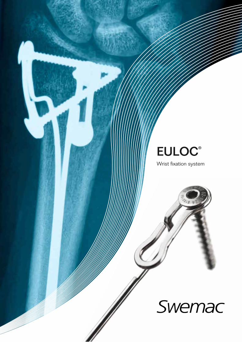
EULOC®
Wrist fixation system

2
The Euloc® is a simple, minimal invasive system for the treatment of displaced radius and ulna fractures with moderate degree of comminution.
The basic principle is that of intra focal Kapandji pinning (Ref. 1,2,3,4,5) i.e. the distal fragment is supported by pins inserted through the fracture line into the proximal fragment of the radius.
The original method has been modified and improved with the Euloc:
• Pins are inserted into the medullary canal of the proximal fragment
• Pins are pre shaped to fit the natural shape of the bone
• Screw fixation through double eyelets
This is the second generation of the Euloc Wrist Fixation system. The first generation has been used in approximately 1500 patients. The present collection of pins and screws is a result of our efforts and the experience of:
Carl Ekholm, M.D., Ph.D. Assoc. Prof. and
Michael Ullman M.D., Ph.D.,
Dept. Orthopaedics, Sahlgrenska University Hospital,
Göteborg, Sweden.
EULOC®
Wrist fixation system
Euloc Patent no. Sweden SE528331C2 Patent application no. PCT/SE2006/000429
3
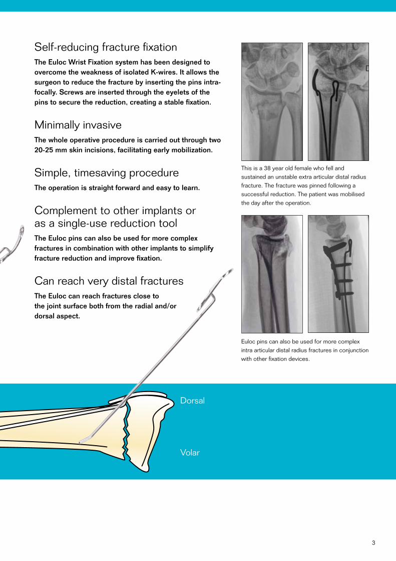
Self-reducing fracture fixationThe Euloc Wrist Fixation system has been designed to overcome the weakness of isolated K-wires. It allows the surgeon to reduce the fracture by inserting the pins intra- focally. Screws are inserted through the eyelets of the pins to secure the reduction, creating a stable fixation.
Minimally invasiveThe whole operative procedure is carried out through two 20-25 mm skin incisions, facilitating early mobilization.
Simple, timesaving procedureThe operation is straight forward and easy to learn.
Complement to other implants or as a single-use reduction tool The Euloc pins can also be used for more complex fractures in combination with other implants to simplify fracture reduction and improve fixation.
Can reach very distal fracturesThe Euloc can reach fractures close to the joint surface both from the radial and/or dorsal aspect.
Dorsal
Volar
Euloc pins can also be used for more complex intra articular distal radius fractures in conjunction with other fixation devices.
This is a 38 year old female who fell and sustained an unstable extra articular distal radius fracture. The fracture was pinned following a successful reduction. The patient was mobilised the day after the operation.
4
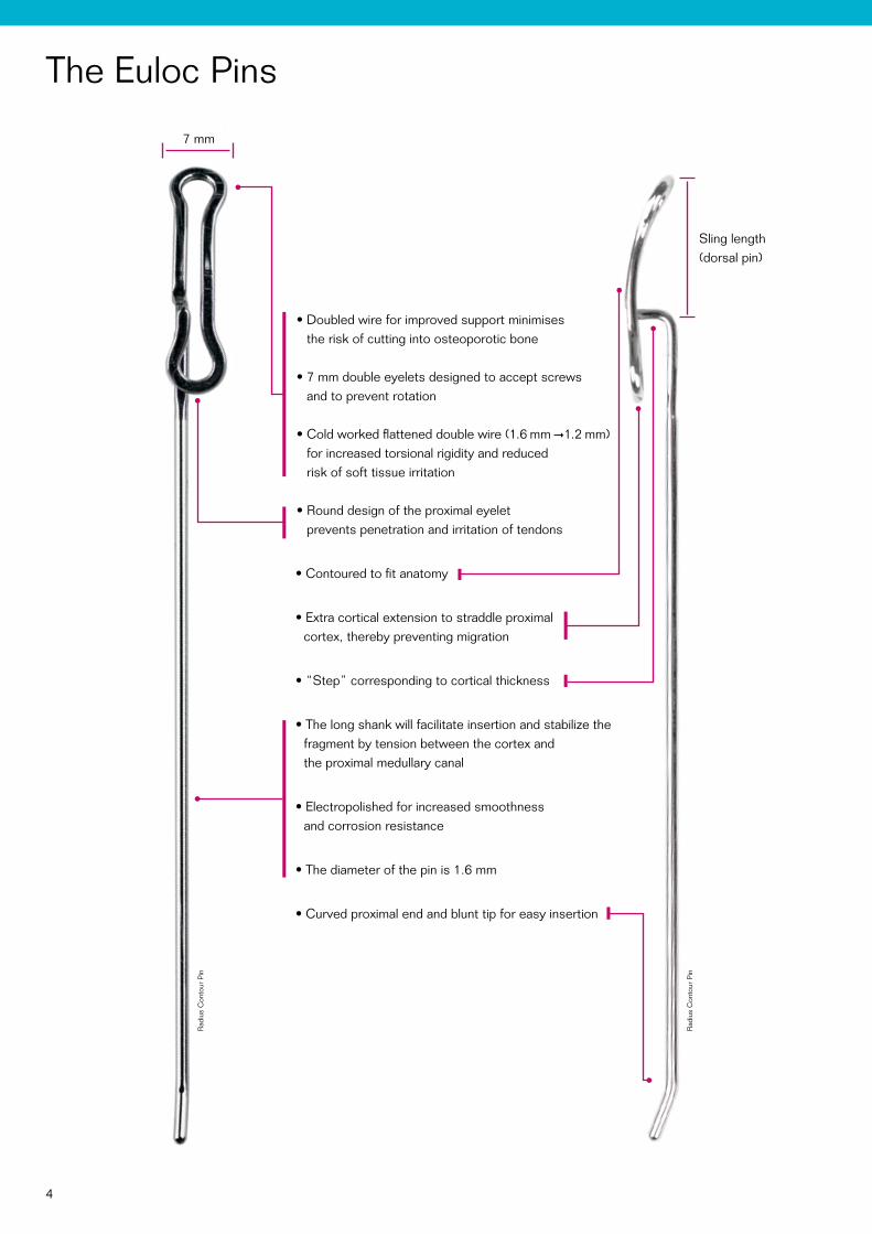
The Euloc Pins
• Doubled wire for improved support minimises the risk of cutting into osteoporotic bone
• 7 mm double eyelets designed to accept screws and to prevent rotation
• Cold worked flattened double wire (1.6 mm 1.2 mm) for increased torsional rigidity and reduced risk of soft tissue irritation
• Round design of the proximal eyelet prevents penetration and irritation of tendons
• Contoured to fit anatomy
• Extra cortical extension to straddle proximal cortex, thereby preventing migration
• “Step” corresponding to cortical thickness
• The long shank will facilitate insertion and stabilize the fragment by tension between the cortex and the proximal medullary canal
• Electropolished for increased smoothness and corrosion resistance
• The diameter of the pin is 1.6 mm
• Curved proximal end and blunt tip for easy insertion
Sling length (dorsal pin)
Rad
ius
Con
tour
Pin
Rad
ius
Con
tour
Pin
7 mm
The Radius Contour Pin is available in left and right.
The Radius Dorsal Pin is available with four different sling lengths; 7 mm, 10 mm, 15 mm and 20 mm.
5
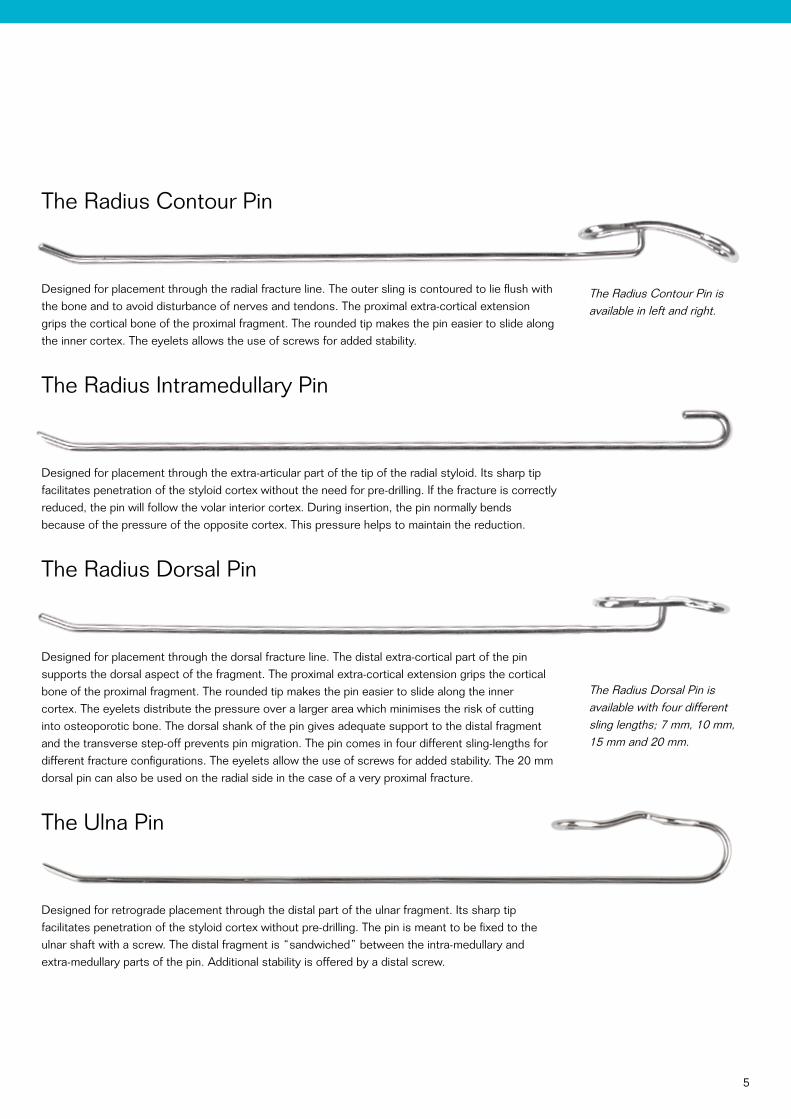
The Radius Contour Pin
Designed for placement through the radial fracture line. The outer sling is contoured to lie flush with the bone and to avoid disturbance of nerves and tendons. The proximal extra-cortical extension grips the cortical bone of the proximal fragment. The rounded tip makes the pin easier to slide along the inner cortex. The eyelets allows the use of screws for added stability.
The Radius Intramedullary Pin
Designed for placement through the extra-articular part of the tip of the radial styloid. Its sharp tip facilitates penetration of the styloid cortex without the need for pre-drilling. If the fracture is correctly reduced, the pin will follow the volar interior cortex. During insertion, the pin normally bends because of the pressure of the opposite cortex. This pressure helps to maintain the reduction.
The Radius Dorsal Pin
Designed for placement through the dorsal fracture line. The distal extra-cortical part of the pin supports the dorsal aspect of the fragment. The proximal extra-cortical extension grips the cortical bone of the proximal fragment. The rounded tip makes the pin easier to slide along the inner cortex. The eyelets distribute the pressure over a larger area which minimises the risk of cutting into osteoporotic bone. The dorsal shank of the pin gives adequate support to the distal fragment and the transverse step-off prevents pin migration. The pin comes in four different sling-lengths for different fracture configurations. The eyelets allow the use of screws for added stability. The 20 mm dorsal pin can also be used on the radial side in the case of a very proximal fracture.
The Ulna Pin
Designed for retrograde placement through the distal part of the ulnar fragment. Its sharp tip facilitates penetration of the styloid cortex without pre-drilling. The pin is meant to be fixed to the ulnar shaft with a screw. The distal fragment is “sandwiched” between the intra-medullary and extra-medullary parts of the pin. Additional stability is offered by a distal screw.
6
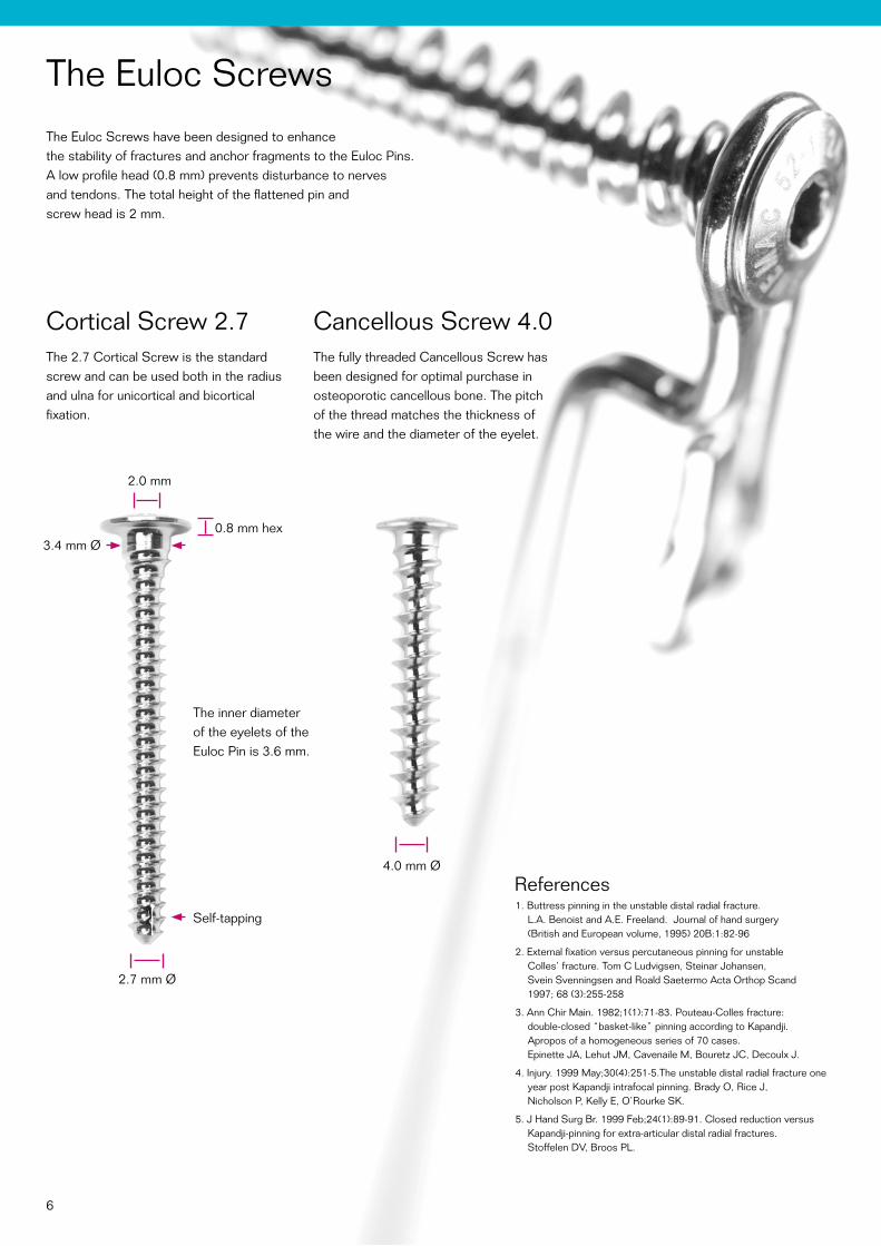
The Euloc ScrewsThe Euloc Screws have been designed to enhance the stability of fractures and anchor fragments to the Euloc Pins. A low profile head (0.8 mm) prevents disturbance to nerves and tendons. The total height of the flattened pin and screw head is 2 mm.
References1. Buttress pinning in the unstable distal radial fracture.
L.A. Benoist and A.E. Freeland. Journal of hand surgery (British and European volume, 1995) 20B:1:82-96
2. External fixation versus percutaneous pinning for unstable Colles’ fracture. Tom C Ludvigsen, Steinar Johansen, Svein Svenningsen and Roald Saetermo Acta Orthop Scand 1997; 68 (3):255-258
3. Ann Chir Main. 1982;1(1):71-83. Pouteau-Colles fracture: double-closed “basket-like” pinning according to Kapandji. Apropos of a homogeneous series of 70 cases. Epinette JA, Lehut JM, Cavenaile M, Bouretz JC, Decoulx J.
4. Injury. 1999 May;30(4):251-5.The unstable distal radial fracture one year post Kapandji intrafocal pinning. Brady O, Rice J, Nicholson P, Kelly E, O’Rourke SK.
5. J Hand Surg Br. 1999 Feb;24(1):89-91. Closed reduction versus Kapandji-pinning for extra-articular distal radial fractures. Stoffelen DV, Broos PL.
Cortical Screw 2.7 The 2.7 Cortical Screw is the standard screw and can be used both in the radius and ulna for unicortical and bicortical fixation.
Cancellous Screw 4.0 The fully threaded Cancellous Screw has been designed for optimal purchase in osteoporotic cancellous bone. The pitch of the thread matches the thickness of the wire and the diameter of the eyelet.
2.7 mm Ø
3.4 mm Ø
4.0 mm Ø
0.8 mm hex
2.0 mm
The inner diameter of the eyelets of the Euloc Pin is 3.6 mm.
Self-tapping
7
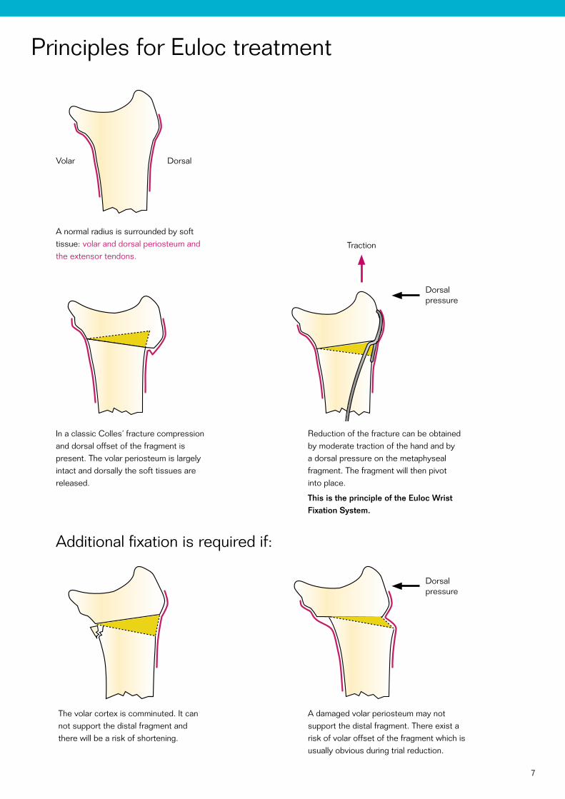
Principles for Euloc treatment
A normal radius is surrounded by soft tissue: volar and dorsal periosteum and the extensor tendons.
Dorsalpressure
Additional fixation is required if:
The volar cortex is comminuted. It can not support the distal fragment and there will be a risk of shortening.
In a classic Colles´ fracture compression and dorsal offset of the fragment is present. The volar periosteum is largely intact and dorsally the soft tissues are released.
A damaged volar periosteum may not support the distal fragment. There exist a risk of volar offset of the fragment which is usually obvious during trial reduction.
Reduction of the fracture can be obtained by moderate traction of the hand and by a dorsal pressure on the metaphyseal fragment. The fragment will then pivot into place.
This is the principle of the Euloc Wrist Fixation System.
Traction
Dorsalpressure
Volar Dorsal

8
Surgical techniqueMain Indications
• Dorsally displaced bending fractures
• Dorsally/radially displaced bending fractures
with or without dorsal comminution
• Dorsally displaced bending fractures
with undisplaced intra articular fragment
• Displaced distal ulna fractures
Additional fixation is required if there is:
• Instability of the volar cortex
Volar displacement
Volar cortex comminution
Severe shortening
• Intra articular comminution (displaced)
General remarksDamage to cutaneous nerves is avoided by correct handling of the soft tissues. The risk of pressure or damage to tendons must be taken into account when placing the pins. When correctly positioned, the distal end of the pin should be close to the cortex, without undue pressure to tendons and soft tissue. The pins do not normally require removal. Even though the pins are pre shaped they may require adjustment to fit the individual patient. This is preferably done with the parallel pliers and the impactor. It is recommended always to use a minimum of one screw in each pin.
Always make sure that the EPL tendon is not compromised by the pin.
Patient positioningThe patient is placed supine on the operating table with the arm abducted 90 degrees over an arm table. A tourniquet is applied and inflated. The patients arm is prepared and draped in the usual sterile manner.
Anaesthesia and antibioticsEither axillary block or general anaesthesia is recommended. Preoperative antibiotics are recommended.
Pre-operative planningThe surgeon should be familiar with the anatomy of the carpal area with special attention to the neuromuscular system.
9
RADIAL CONTOUR PIN
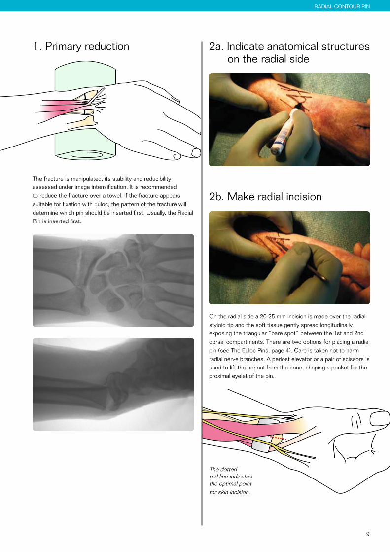
1. Primary reduction
The fracture is manipulated, its stability and reducibility assessed under image intensification. It is recommended to reduce the fracture over a towel. If the fracture appears suitable for fixation with Euloc, the pattern of the fracture will determine which pin should be inserted first. Usually, the Radial Pin is inserted first.
2a. Indicate anatomical structures on the radial side
2b. Make radial incision
On the radial side a 20-25 mm incision is made over the radial styloid tip and the soft tissue gently spread longitudinally, exposing the triangular ”bare spot” between the 1st and 2nd dorsal compartments. There are two options for placing a radial pin (see The Euloc Pins, page 4). Care is taken not to harm radial nerve branches. A periost elevator or a pair of scissors is used to lift the periost from the bone, shaping a pocket for the proximal eyelet of the pin.
The dotted red line indicates the optimal point for skin incision.
10
RADIAL CONTOUR PIN
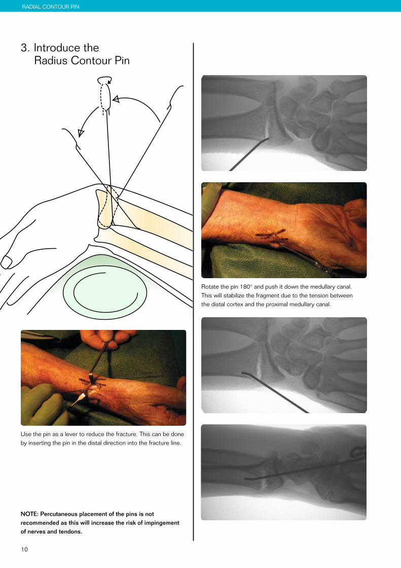
3. Introduce the Radius Contour Pin
Use the pin as a lever to reduce the fracture. This can be done by inserting the pin in the distal direction into the fracture line.
NOTE: Percutaneous placement of the pins is not recommended as this will increase the risk of impingement of nerves and tendons.
Rotate the pin 180° and push it down the medullary canal. This will stabilize the fragment due to the tension between the distal cortex and the proximal medullary canal.
11
RADIAL CONTOUR PIN
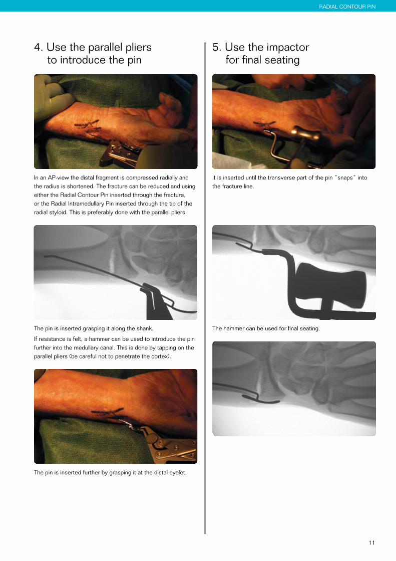
5. Use the impactor for final seating
It is inserted until the transverse part of the pin ”snaps” into the fracture line.
The hammer can be used for final seating.
4. Use the parallel pliers to introduce the pin
In an AP-view the distal fragment is compressed radially and the radius is shortened. The fracture can be reduced and using either the Radial Contour Pin inserted through the fracture, or the Radial Intramedullary Pin inserted through the tip of the radial styloid. This is preferably done with the parallel pliers.
The pin is inserted grasping it along the shank.
If resistance is felt, a hammer can be used to introduce the pin further into the medullary canal. This is done by tapping on the parallel pliers (be careful not to penetrate the cortex).
The pin is inserted further by grasping it at the distal eyelet.
12
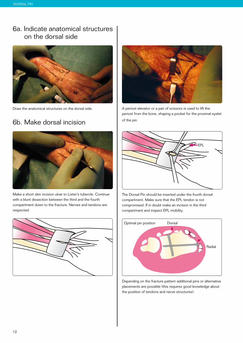
on the dorsal side
A periost elevator or a pair of scissors is used to lift the periost from the bone, shaping a pocket for the proximal eyelet
of the pin.
EPL
The Dorsal Pin should be inserted under the fourth dorsal compartment. Make sure that the EPL tendon is not compromised. If in doubt make an incision in the third compartment and inspect EPL mobility.
Depending on the fracture pattern additional pins or alternative placements are possible (this requires good knowledge about the position of tendons and nerve structures).
DORSAL PIN
6a. Indicate anatomical structures on the dorsal side
Draw the anatomical structures on the dorsal side.
6b. Make dorsal incision
Make a short skin incision ulnar to Lister’s tubercle. Continue with a blunt dissection between the third and the fourth compartment down to the fracture. Nerves and tendons are respected.
Radial
DorsalOptimal pin position
13
DORSAL PIN
7. Introduce the Dorsal Pin
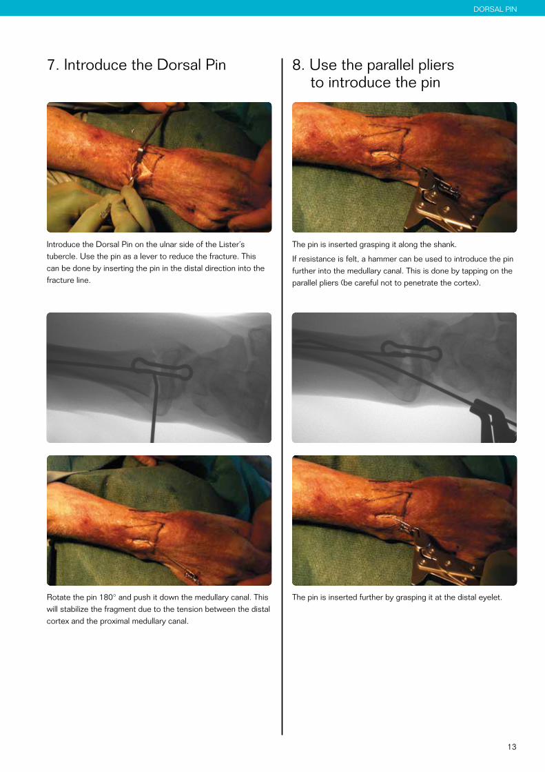
Introduce the Dorsal Pin on the ulnar side of the Lister´s tubercle. Use the pin as a lever to reduce the fracture. This can be done by inserting the pin in the distal direction into the fracture line.
Rotate the pin 180° and push it down the medullary canal. This will stabilize the fragment due to the tension between the distal cortex and the proximal medullary canal.
8. Use the parallel pliers to introduce the pin
The pin is inserted grasping it along the shank.
If resistance is felt, a hammer can be used to introduce the pin further into the medullary canal. This is done by tapping on the parallel pliers (be careful not to penetrate the cortex).
The pin is inserted further by grasping it at the distal eyelet.
14
DORSAL PIN
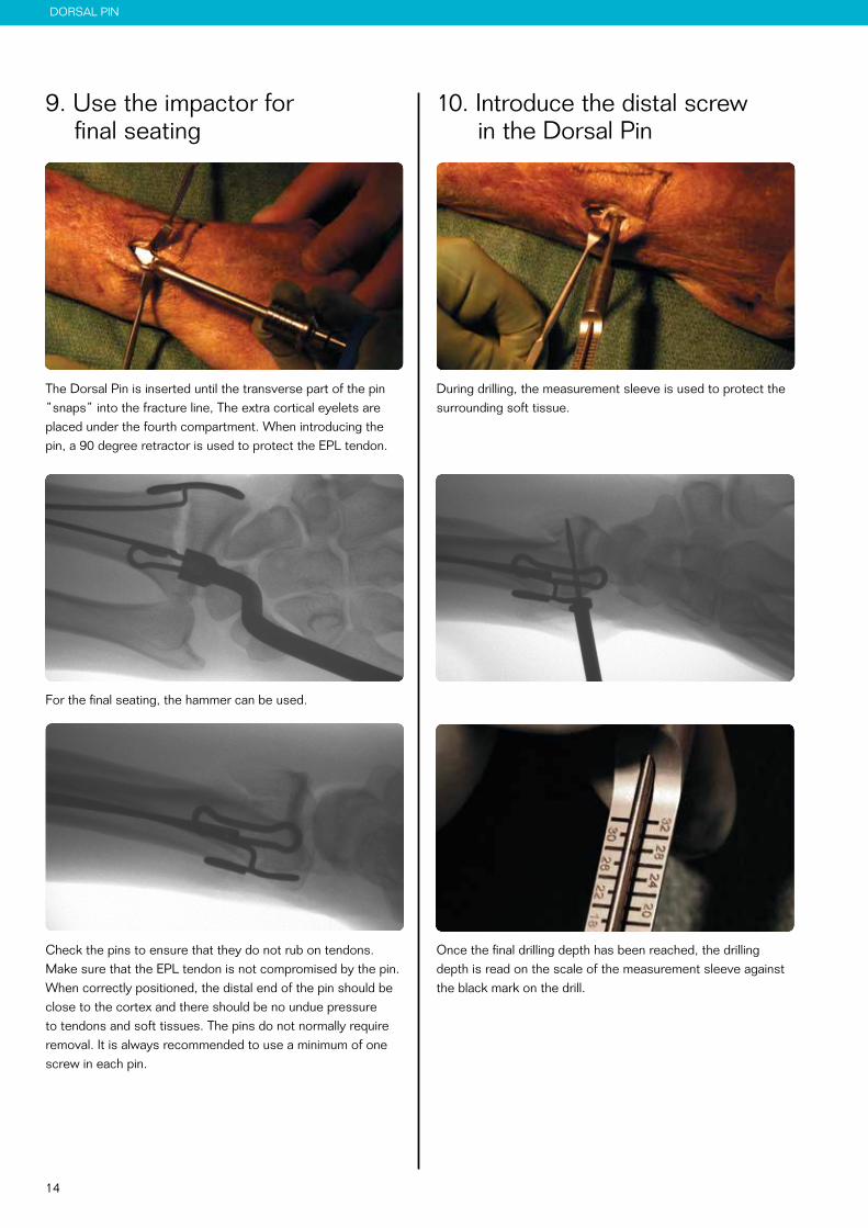
10. Introduce the distal screw in the Dorsal Pin
During drilling, the measurement sleeve is used to protect the surrounding soft tissue.
If the pin is placed in the 4th compartment, make sure the finger extensors are running free.
Once the final drilling depth has been reached, the drilling depth is read on the scale of the measurement sleeve against the black mark on the drill.
9. Use the impactor for final seating
The Dorsal Pin is inserted until the transverse part of the pin ”snaps” into the fracture line, The extra cortical eyelets are placed under the fourth compartment. When introducing the pin, a 90 degree retractor is used to protect the EPL tendon.
For the final seating, the hammer can be used.
If the pin is placed in the 4th compartment, make sure the finger extensors are running free.
Check the pins to ensure that they do not rub on tendons. Make sure that the EPL tendon is not compromised by the pin. When correctly positioned, the distal end of the pin should be close to the cortex and there should be no undue pressure to tendons and soft tissues. The pins do not normally require removal. It is always recommended to use a minimum of one screw in each pin.
15
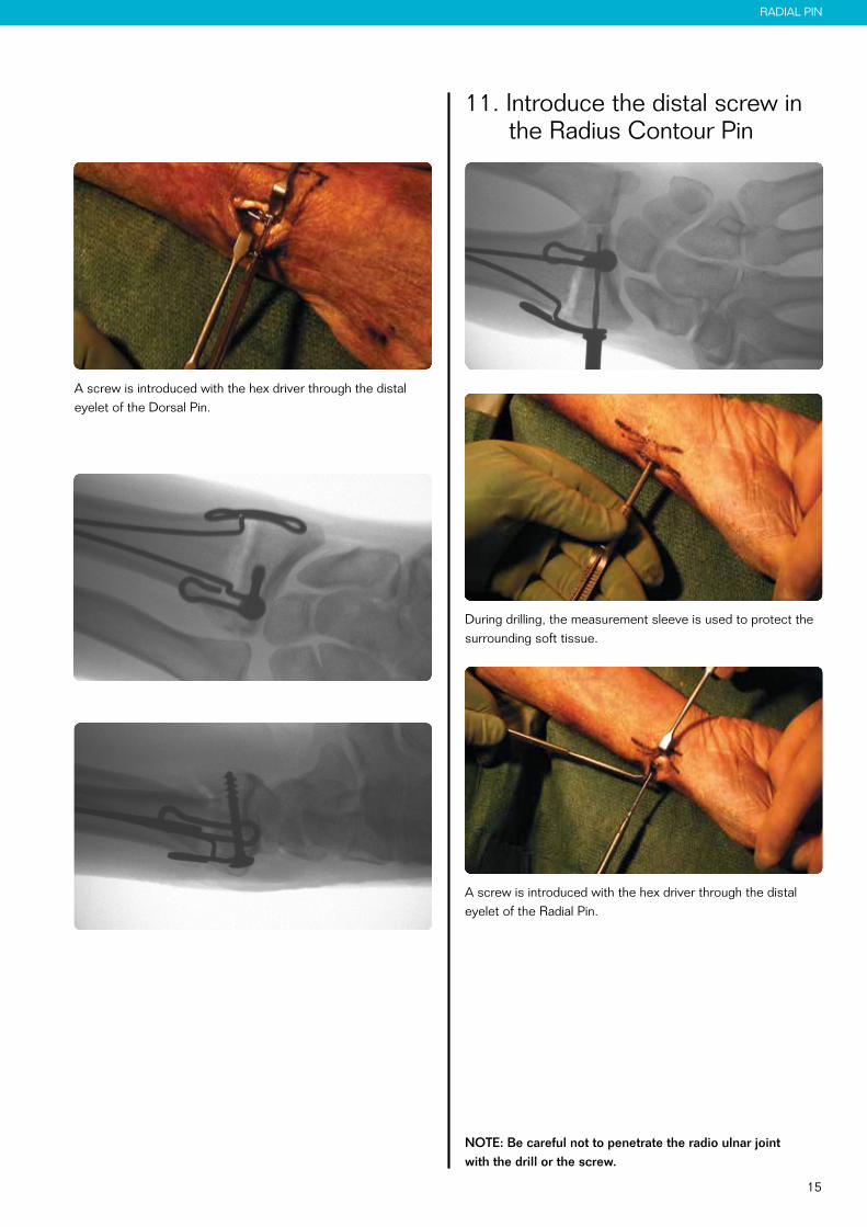
RADIAL PIN
A screw is introduced with the hex driver through the distal eyelet of the Dorsal Pin.
11. Introduce the distal screw in the Radius Contour Pin
During drilling, the measurement sleeve is used to protect the surrounding soft tissue.
A screw is introduced with the hex driver through the distal eyelet of the Radial Pin.
NOTE: Be careful not to penetrate the radio ulnar joint with the drill or the screw.

16
13. Proximal screw fixation
If additional fixation is needed to achieve a more stable fixation, the proximal screws should be used. The proximal screws are inserted in the same way as the distal screws. When using both distal and proximal screws, the Euloc turns into a self reducing, fragment specific plating system, offering a very stable fixation.
Post operative careDuring the first 2-4 weeks after the surgery, a dorsal splint or a wrist brace, with the wrist in neutral position is recommended.
Early active mobilisation of hand, elbow and shoulder should be started from the first day after surgery. Shoulder activity is the most important and effective way in reducing swelling of the hand.
12. Check fracture stability
Once the pins and the distal screws are inserted, fracture stability is assessed. If fracture stability has been achieved, the wound is closed with a 4-0 resorbable suture.
17
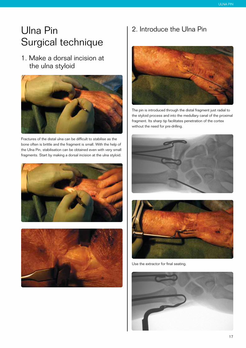
ULNA PIN
Ulna Pin Surgical technique 1. Make a dorsal incision at
the ulna styloid
Fractures of the distal ulna can be difficult to stabilise as the bone often is brittle and the fragment is small. With the help of the Ulna Pin, stabilisation can be obtained even with very small fragments. Start by making a dorsal incision at the ulna styloid.
2. Introduce the Ulna Pin
The pin is introduced through the distal fragment just radial to the styloid process and into the medullary canal of the proximal fragment. Its sharp tip facilitates penetration of the cortex without the need for pre-drilling.
Use the extractor for final seating.
18
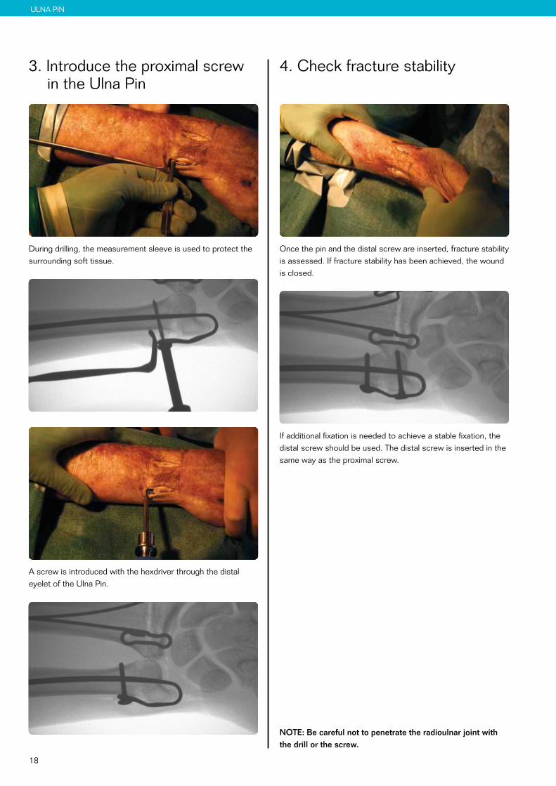
ULNA PIN
4. Check fracture stability
Once the pin and the distal screw are inserted, fracture stability is assessed. If fracture stability has been achieved, the wound is closed.
If additional fixation is needed to achieve a stable fixation, the distal screw should be used. The distal screw is inserted in the same way as the proximal screw.
NOTE: Be careful not to penetrate the radioulnar joint with the drill or the screw.
3. Introduce the proximal screw in the Ulna Pin
During drilling, the measurement sleeve is used to protect the surrounding soft tissue.
A screw is introduced with the hexdriver through the distal eyelet of the Ulna Pin.
19
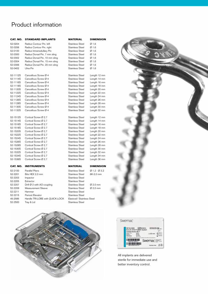
CAT. NO. STANDARD IMPLANTS MATERIAL DIMENSION
52-0204 Radius Contour Pin, left Stainless Steel Ø 1,6 52-0206 Radius Contour Pin, right Stainless Steel Ø 1,6 52-0100 Radius Intramedullary Pin Stainless Steel Ø 1,6 52-0300 Radius Dorsal Pin, 7 mm sling Stainless Steel Ø 1,6 52-0302 Radius Dorsal Pin, 10 mm sling Stainless Steel Ø 1,6 52-0304 Radius Dorsal Pin, 15 mm sling Stainless Steel Ø 1,6 52-0306 Radius Dorsal Pin, 20 mm sling Stainless Steel Ø 1,6 52-0402 Ulna Pin Stainless Steel Ø 1,6
52-1112S Cancellous Screw Ø 4 Stainless Steel Length 12 mm 52-1114S Cancellous Screw Ø 4 Stainless Steel Length 14 mm 52-1116S Cancellous Screw Ø 4 Stainless Steel Length 16 mm 52-1118S Cancellous Screw Ø 4 Stainless Steel Length 18 mm 52-1120S Cancellous Screw Ø 4 Stainless Steel Length 20 mm 52-1122S Cancellous Screw Ø 4 Stainless Steel Length 22 mm 52-1124S Cancellous Screw Ø 4 Stainless Steel Length 24 mm 52-1126S Cancellous Screw Ø 4 Stainless Steel Length 26 mm 52-1128S Cancellous Screw Ø 4 Stainless Steel Length 28 mm 52-1130S Cancellous Screw Ø 4 Stainless Steel Length 30 mm 52-1132S Cancellous Screw Ø 4 Stainless Steel Length 32 mm
52-1512S Cortical Screw Ø 2,7 Stainless Steel Length 12 mm 52-1514S Cortical Screw Ø 2,7 Stainless Steel Length 14 mm 52-1516S Cortical Screw Ø 2,7 Stainless Steel Length 16 mm 52-1518S Cortical Screw Ø 2,7 Stainless Steel Length 18 mm 52-1520S Cortical Screw Ø 2,7 Stainless Steel Length 20 mm 52-1522S Cortical Screw Ø 2,7 Stainless Steel Length 22 mm 52-1524S Cortical Screw Ø 2,7 Stainless Steel Length 24 mm 52-1526S Cortical Screw Ø 2,7 Stainless Steel Length 26 mm 52-1528S Cortical Screw Ø 2,7 Stainless Steel Length 28 mm 52-1530S Cortical Screw Ø 2,7 Stainless Steel Length 30 mm 52-1532S Cortical Screw Ø 2,7 Stainless Steel Length 32 mm52-1534S Cortical Screw Ø 2,7 Stainless Steel Length 34 mm52-1536S Cortical Screw Ø 2,7 Stainless Steel Length 36 mm CAT. NO. INSTRUMENTS MATERIAL DIMENSION
52-2100 Parallel Pliers Stainless Steel Ø 1,2 - Ø 3,2 52-2201 Bits HEX 2,0 mm Stainless Steel 6K-2,0 mm 52-2203 Impactor Stainless Steel 52-2205 Extractor Stainless Steel 52-2207 Drill Ø 2 with AO-coupling Stainless Steel Ø 2,0 mm 52-2209 Measurement Sleeve Stainless Steel Ø 2,0 mm 52-2211 Hammer Stainless Steel 52-2215 Periost Elevator Stainless Steel 45-2585 Handle TRI-LOBE with QUICK-LOCK Elastosil/ Stainless Steel 52-2500 Tray & Lid Stainless Steel
Product information
All implants are delivered sterile for immediate use and better inventory control.

Swemac develops and promotes innovative solutions for fracture treatment and joint replacement. We create outstanding value for our clients and their patients by being the most competent and reliable partner.
Manufacturer: Swemac Innovation AB 0413 Cobolgatan 1 • SE-583 35 Linköping • Sweden
Sales and distribution: Swemac Orthopaedics AB Cobolgatan 1 • SE-583 35 Linköping • Sweden Phone +46 13 37 40 30 • Fax +46 13 14 00 26 E-mail [email protected] • www.swemac.com
P135-28-20170426
Print date: 2017-12-14
Euloc Wrist Fixation System
IFUFor the latest version of this Instruction For Use. Please visit: http://download.swemac.com/Euloc-Wrist-Fixation-System