wrist variax distal radius locking plate...
TRANSCRIPT

VariAx Distal Radius Locking Plate System
Wri
st
Wrist
Operative Technique• Anatomical & Universal Volar Plates
• Dorsal Plates
• Fragment Specific Plates
• XXL Anatomical Volar Plates

2
VariAx Distal Radius Locking Plate System
This publication sets forth detailed recommended procedures for using Stryker Osteosynthesis devices and instruments.
It offers guidance that you should heed, but as with any such technical guide, each surgeon must consider the particular needs of each patient and make appropriate adjustments when and as required.
A workshop training is recommended prior to first surgery.
All non-sterile devices must be cleaned and sterilized before use. Follow the appropriate instructions for use (IFU). For additional information please refer to the instructions in our reprocessing guide (L24002000). Multi-component instruments must be disassembled for cleaning. Please refer to the corresponding assembly/disassembly instructions.
See package insert (90-03200, 90-01953) for a complete list of potential adverse effects, contraindications, warnings and precautions. The surgeon must discuss all relevant risks, including the finite lifetime of the device, with the patient, when necessary.
Warning: Fixation Screws:
Stryker Osteosynthesis bone screws are not approved or intended for screw attachment or fixation to the posterior elements (pedicles) of the cervical, thoracic or lumbar spine.

3
Page
1. Indications, Precautions & Contraindications 4
Intended Use 4
Precautions 4
Indications 4
Contraindications 4
2. Overview 5
Plate Options 5
Screw/Peg Options 5
3. Operative Technique 8
Anatomical Volar Plate 8
Universal Volar Plate 10
Dorsal Plate 12
Lateral Distal Radius Plate 14
Aiming Block 17
Contents

4
Indications, Precautions & Contraindications
PrecautionsStryker Osteosynthesis systems have not been evaluated for safety and use in MR environment and have not been tested for heating or migration in the MR environment, unless specified otherwise in the product labeling.
Contraindications• Inadequate bone quantity and quality
• Patients with active infections
• Patients with metal allergies and foreign body sensitivity
• Severely non-compliant patients with mental or neurological conditions who are unwilling or incapable of following postoperative care instructions
• Patients with limited blood supply or insufficient quality or quantity of bone
• Patients with unstable physical and/or mental health conditions
Indications Compression, intra-articular and extra-articular fractures, and displaced fractures. Following additional indications apply only for the XXL Volar Distal Radius Plates: Osteotomies, non-unions, and malunions.
Intended Use The VariAx Distal Radius Locking System including the XXL Volar Distal Radius Plates is intended for internal fixation of small bone fractures, primarily including distal radius fractures.

5
Overview
2.7mm Locking
Screw
2.3mmLocking
Screw
Screw/Peg Options2.0mmSmooth Locking
Peg
2.3mmNon-
LockingScrew
2.7mmNon-
LockingScrew
2.7mmPartialThread
Non-LockingScrew
2.7mmPartial ThreadLocking
Screw
Plate Options
Cross-PinT7 Drive
Locking ScrewLocking Screw
Non-Locking ScrewNon-Locking Screw
Note: • Locking and Non-Locking screws
can be used in any round hole.
• To avoid disengagement of the screwdriver blade from the screw during insertion, axial pressure is recommended.
Universal Volar Plates
Dorsal Plates Lateral
DR PlateDorsal Medial
DR Plate
XXL Anatomical Volar Plates
Anatomical Volar Plates
Standard
Note: Plates are not scaled to size.
Anatomical Volar Plates
Narrow
Anatomical Volar Plates
Intermediate

6
Overview
15° distal15° lateral
12° proximal
5° proximal
5° proximal
18° distal12° lateral
0°
0°
18° distal12° lateral
15° distal15° lateral
10° proximal
5° proximal
0°
Pre-determined Screw Pattern
SmartLock Polyaxial Drill Guide (56-01250)
Allows for ±15 degrees of custom angulation and may be used for more complex fractures. A lip on the drill sleeve will engage and allow toggling in the hole. The range in which the drill guide toggles will create a 30-degree cone and every angle in this range will be a locking position. This may allow the surgeon to aim where the screw/peg should be placed. Also, depending on the placement of the plate, there may be a need to angle a screw/peg out of the fracture line.
Note: Using one of the provided drill guides for screw hole preparation is mandatory. Not using a drill guide may lead to drilling out of specified locking range and compromise the locking capabilities.
Fixed Angle Drill Guide (56-01255)
This drill guide can be used to help ensure placement of screw options at a fixed angle. It is designed to fit in the pre-tilted lips within the holes on the plate by simply pressing the drill guide into the hole.
Note: In order to prevent toggling, this
drill guide is designed to fit very tightly into the holes of the plate. When utilizing this instrument follow the same trajectory of the pre-tilted lips to facilitate its placement.
Note: First fully engage the drill guide in the hole and then aim the drill in the desired direction.
7
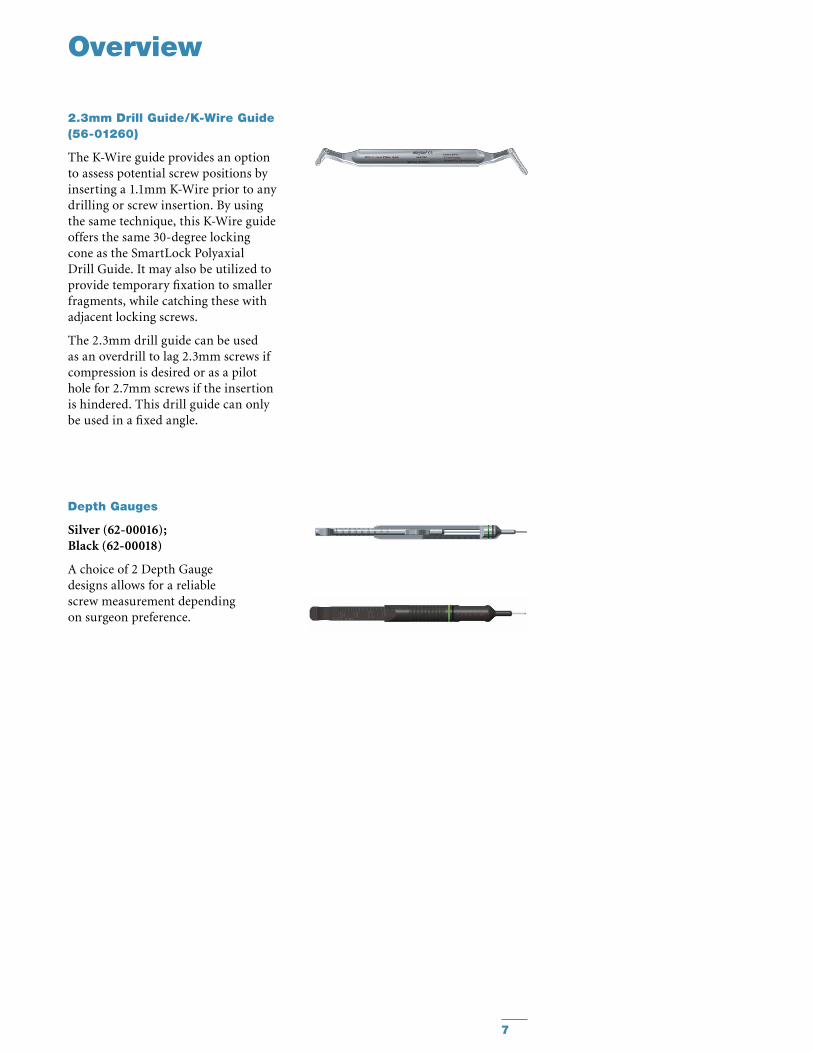
Depth Gauges
Silver (62-00016); Black (62-00018)
A choice of 2 Depth Gauge designs allows for a reliable screw measurement depending on surgeon preference.
2.3mm Drill Guide/K-Wire Guide (56-01260)
The K-Wire guide provides an option to assess potential screw positions by inserting a 1.1mm K-Wire prior to any drilling or screw insertion. By using the same technique, this K-Wire guide offers the same 30-degree locking cone as the SmartLock Polyaxial Drill Guide. It may also be utilized to provide temporary fixation to smaller fragments, while catching these with adjacent locking screws.
The 2.3mm drill guide can be used as an overdrill to lag 2.3mm screws if compression is desired or as a pilot hole for 2.7mm screws if the insertion is hindered. This drill guide can only be used in a fixed angle.
Overview
8
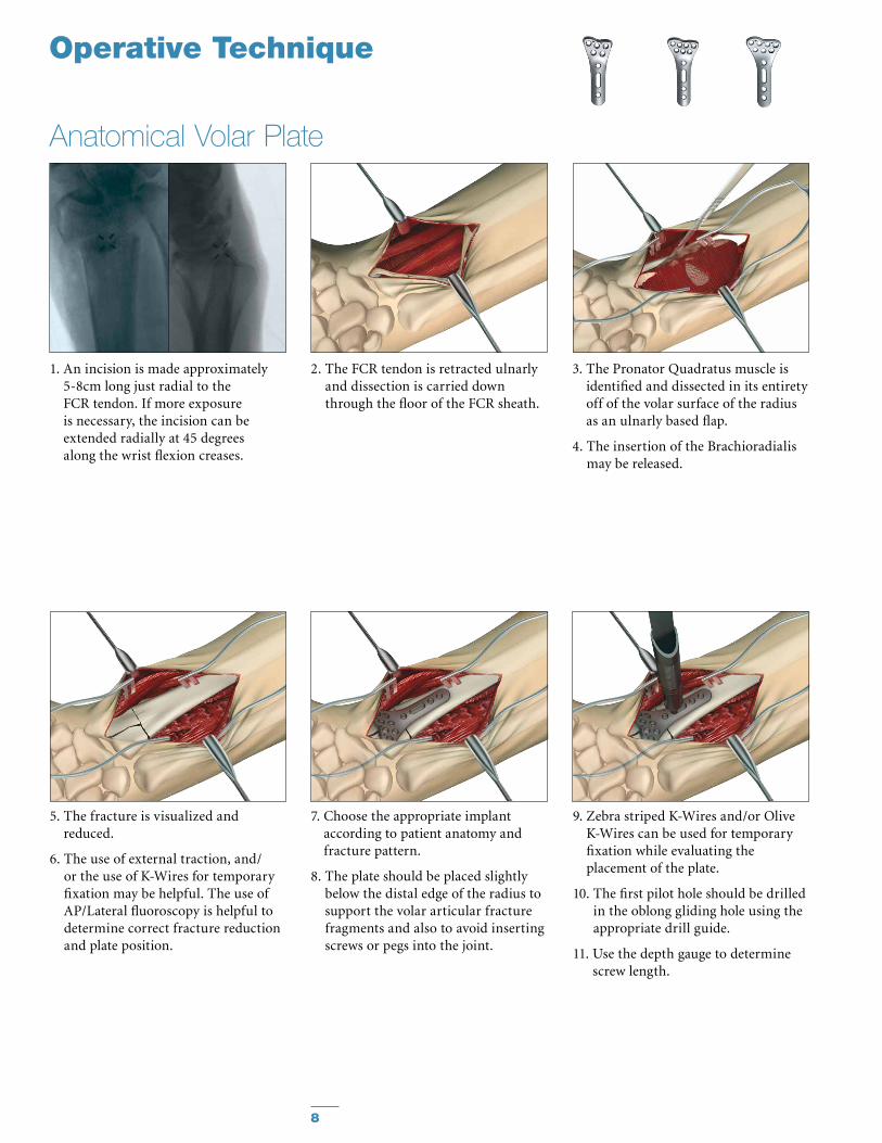
Anatomical Volar Plate
2. The FCR tendon is retracted ulnarly and dissection is carried down through the floor of the FCR sheath.
1. An incision is made approximately 5-8cm long just radial to the FCR tendon. If more exposure is necessary, the incision can be extended radially at 45 degrees along the wrist flexion creases.
3. The Pronator Quadratus muscle is identified and dissected in its entirety off of the volar surface of the radius as an ulnarly based flap.
4. The insertion of the Brachioradialis may be released.
Operative Technique
5. The fracture is visualized and reduced.
6. The use of external traction, and/or the use of K-Wires for temporary fixation may be helpful. The use of AP/Lateral fluoroscopy is helpful to determine correct fracture reduction and plate position.
7. Choose the appropriate implant according to patient anatomy and fracture pattern.
8. The plate should be placed slightly below the distal edge of the radius to support the volar articular fracture fragments and also to avoid inserting screws or pegs into the joint.
9. Zebra striped K-Wires and/or Olive K-Wires can be used for temporary fixation while evaluating the placement of the plate.
10. The first pilot hole should be drilled in the oblong gliding hole using the appropriate drill guide.
11. Use the depth gauge to determine screw length.

9
Note: In hard, cortical bone a 2.3mm cortical drill bit (60-23341) or the 2.7mm tap (62-27010) may be used to insert the 2.7mm screw to help reduce the risk of screw breakage during insertion.
Note: The tips of the screws in the distal holes should not stick out
at the far cortex to avoid damage of the extensor tendons.
Anatomical Volar Plate
Operative Technique
12. A non-locking screw is placed in the oblong gliding hole but not completely tightened to allow adjustment of the plate in distal or proximal directions.
13. After confirmation of the correct positioning of the anatomic volar plate by use of fluoroscopy, tighten the first screw.
14. Once the position of the plate has been determined, it is time to decide which drill guide to use based upon preference and/or fracture pattern.
15. Using the desired drill guide, repeat drilling, measuring and placement of screws/pegs in the distal holes.
16. Place locking or non-locking screws in the proximal end of the plate.
17. Verify proper placement of screws/pegs by use of fluoroscopy to ensure that neither penetrate the joint.
18. Close the incision.

10
Operative Technique
1. An incision is made approximately 5-8cm long directly over the FCR tendon. If more exposure is necessary, the incision can be extended radially at 45 degrees along the wrist flexion creases.
2. The FCR tendon is retracted ulnarly and dissection is carried down through the floor of the FCR sheath.
3. The Pronator Quadratus muscle is identified and dissected in its entirety off of the volar surface of the radius as an ulnarly based flap.
4. The insertion of the Brachioradialis may be released.
5. The fracture is visualized.
6. The fracture is reduced. The use of external traction, and/or the use of K-Wires for temporary fixation could be helpful.
7. The plate should be placed slightly below the distal edge of the distal radius to avoid inserting screws or pegs into the joint. The use of AP/Lat fluoroscopy is helpful to determine correct fracture reduction and plate position.
8. K-Wires can be used for temporary fixation.
9. The first pilot hole should be drilled in the oblong gliding hole using the appropriate drill guide.
10. Measure the depth of the hole to determine screw length.
11. The screw is placed in the oblong gliding hole but not completely tightened to allow adjustment of the plate in distal or proximal directions.
Universal Volar Plate

11
Operative Technique
12. After confirmation of the correct positioning of the volar plate by use of fluoroscopy, tighten the first screw.
13. Repeat drilling, measuring and placing of screws/pegs in the distal holes of the plate. The position and number of screws applied depends on the type of fracture.
14. Place Non-Locking or Locking screws in the proximal end of the plate.
15. Verify proper placement of screws and pegs by use of fluoroscopy to ensure that neither penetrates the joint.
16. Close the incision.
Universal Volar Plate
Note: In hard, cortical bone a 2.3mm cortical drill bit (60-23341) or the 2.7mm tap (62-27010) may be used to insert the 2.7mm screw to help reduce the risk of screw breakage during insertion.
Note: The tips of the screws in the distal holes should not stick out
at the far cortex to avoid damage of the extensor tendons.

12
1. Longitudinal incision is made just ulnar to Lister’s tubercle at the distal radius region.
2. Dissection is performed down to the extensor retinaculum. The third compartment is opened and the extensor pollicis longus is displaced radially.
3. The second compartment wrist extensors are subperiosteally elevated radially and the fourth compartment is subperiosteally elevated ulnarly. The terminal branches of the posterior interosseous nerve may be excised for pain reduction.
4. The fracture is reduced. The use of an external traction device and/or K-Wires for temporary fixation may be helpful.
5. If necessary, adapt the plate for correct anatomical position. Removal of Lister's Tubercle might be necessary.
6. The plate should be placed slightly proximal the distal edge of the distal radius to avoid inserting screws/pegs into the joint. Correct positioning of the plate should be confirmed by use of fluoroscopy. The first pilot hole should be drilled in the oblong gliding hole.
Dorsal Plate
7. Measure the depth of the hole to determine screw length.
8. The screw is placed in the oblong gliding hole but not completely tightened to allow adjustment of the plate in a distal or proximal direction.
Operative Technique

13
Operative Technique
9. Confirm proper plate positioning by use of fluoroscopy and then tighten the first screw.
Note: Screw length may need to be
changed after plate is fully seated on bone.
10. Repeat drilling, measuring, and placing of screws/pegs into the distal holes of the plate. The position and number of screws applied depends on the type of fracture.
11. Place Non-Locking or Locking screws in the proximal end of the plate.
12. Verify proper placement of screws and pegs by use of fluoroscopy to ensure that they do not penetrate the joint.
13. Close the incision.
Dorsal Plate
Note: In hard, cortical bone a 2.3mm cortical drill bit (60-23341) or the 2.7mm
tap (62-27010) may be used to insert the 2.7mm screw to help reduce the risk of screw breakage during insertion.

14
Lateral Distal Radius Plate
Operative Technique
1. An incision is made along the radial column.
2. Care must be taken to avoid injury to the superficial branch of the radial nerve.
3. The first dorsal compartment is released. The tendons are retracted volarly.
4. The fracture should be reduced and stabilized with a K-Wire placed from the distal radial styloid and aimed dorsal and proximal.
Note: Fragment specific plates should
not be used in isolation.

15
Operative Technique
Lateral Distal Radius Plate5. The plate is slipped over the K-Wire
and placed along the radial column.
6. A Non-Locking screw placed in the oblong hole will compress the plate to the shaft, and by pulling the plate proximally will compress the fracture site.

16
Operative Technique
Lateral Distal Radius Plate7. The 3 in 1 K-Wire bender/cutter/
inserter is used to bend K-Wires distally.
8. It is recommended only one K-Wire be placed distally at a time in order to make proper use of the bender/cutter/inserter instrument.
9. After insertion, the tamp and mallet can be used to further insert the K-Wires.
10. K-Wires and screws can be placed in conjunction for more rigid fixation.
11. The incision is closed.
17
Operative Technique
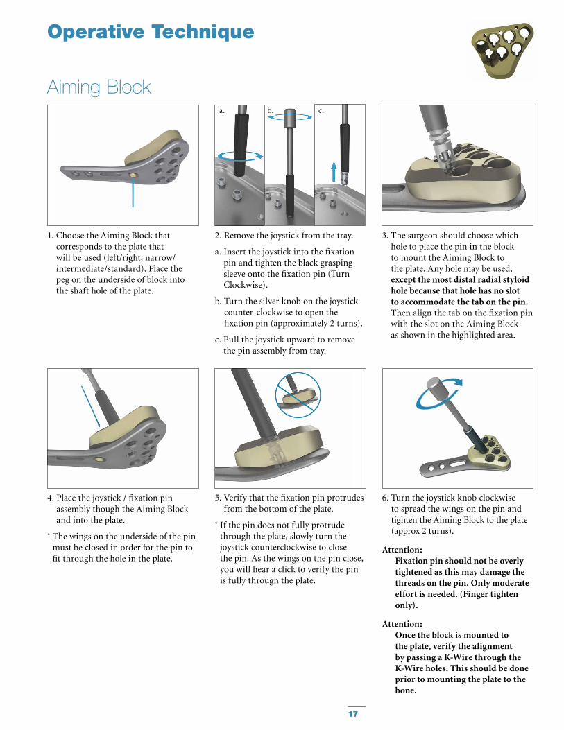
Aiming Block
1. Choose the Aiming Block that corresponds to the plate that will be used (left/right, narrow/intermediate/standard). Place the peg on the underside of block into the shaft hole of the plate.
2. Remove the joystick from the tray.
a. Insert the joystick into the fixation pin and tighten the black grasping sleeve onto the fixation pin (Turn Clockwise).
b. Turn the silver knob on the joystick counter-clockwise to open the fixation pin (approximately 2 turns).
c. Pull the joystick upward to remove the pin assembly from tray.
3. The surgeon should choose which hole to place the pin in the block to mount the Aiming Block to the plate. Any hole may be used, except the most distal radial styloid hole because that hole has no slot to accommodate the tab on the pin. Then align the tab on the fixation pin with the slot on the Aiming Block as shown in the highlighted area.
4. Place the joystick / fixation pin assembly though the Aiming Block and into the plate.
* The wings on the underside of the pin must be closed in order for the pin to fit through the hole in the plate.
5. Verify that the fixation pin protrudes from the bottom of the plate.
* If the pin does not fully protrude through the plate, slowly turn the joystick counterclockwise to close the pin. As the wings on the pin close, you will hear a click to verify the pin is fully through the plate.
6. Turn the joystick knob clockwise to spread the wings on the pin and tighten the Aiming Block to the plate (approx 2 turns).
Attention: Fixation pin should not be overly
tightened as this may damage the threads on the pin. Only moderate effort is needed. (Finger tighten only).
Attention: Once the block is mounted to
the plate, verify the alignment by passing a K-Wire through the K-Wire holes. This should be done prior to mounting the plate to the bone.
a. b. c.

18
Operative Technique
Aiming Block
11. Drill through the drill guide or drill sleeve. The scale on the drill bit can be used to determine the appropriate screw length.
Attention: To prevent damage to the Aiming
Block and/or plate, the variable angle drill guide must be used.
Note: If the intermediate plate aiming
block is used, the recommended position of the joystick/fixation pin is the most proximal medial hole of the aiming block. This ensures that all open holes can be accessed with the drill sleeve. If the joystick is placed in the proximal lateral or middle hole then the adjacent hole as shown here will not be accessible with the drill sleeve.
Intermediate Aiming Blocks and Plate
10. Alternative to the use of the drill guide, an Aiming Block Drill Sleeve can be used to drill the pilot hole. Simply push the drill sleeve through an aiming block hole until fully seated. It is possible to insert two drill sleeves concurrently in the distal row of the aiming block to facilitate the drilling process.
12. Measure depth with the depth gauge and choose the appropriate screw. Ensure that the tip of the measuring gauge is fully seated onto the plate.
13. Screw can be inserted through the Aiming Block. Confirm screw placement under fluoroscopy.
7. The joystick may be used to help position the plate on the bone. After plate is positioned, remove the joystick by loosening the black grasping sleeve from the fixation pin (counter clockwise).
Caution: Aiming Block cannot be used with plates that
have been intra-operatively contoured or bent.
8. K-Wires may be used through the plate / block assembly for temporary fixation.
9. The variable angle drill guide can be used in any hole to drill for the pre-determined trajectory.

19
14. Removal of Aiming Block
a. Attach the joystick to the fixation pin by tightening the black grasping sleeve. (clockwise)
b. Turn the joystick knob counter- clockwise to open fixation the pin. (approx 2 turns)
15. Remove the joystick/fixation pin assembly from the Aiming Block.
16. Remove Aiming Block from the plate. If necessary a screw can be placed in hole used for fixation of the Aiming Block. Ensure that all screw heads are fully seated onto the plate and fully tightened.
Optional Steps:
Under fluoroscopy, the K-Wire will approximate the trajectory of the adjacent screw on the ulnar side.
Note: There is no K-Wire hole
to approximate the distal most radial styloid screw.
Note: Left block is shown.
Operative Technique
Aiming Blocka. b.

This document is intended solely for the use of healthcare professionals. A surgeon must always rely on his or her own professional clinical judgment when deciding whether to use a particular product when treating a particular patient. Stryker does not dispense medical advice and recommends that surgeons be trained in the use of any particular product before using it in surgery.
The information presented is intended to demonstrate a Stryker product. A surgeon must always refer to the package insert, product label and/or instructions for use, including the instructions for Cleaning and Sterilization (if applicable), before using any Stryker product. Products may not be available in all markets because product availability is subject to the regulatory and/or medical practices in individual markets. Please contact your Stryker representative if you have questions about the availability of Stryker products in your area.
Stryker Corporation or its divisions or other corporate affiliated entities own, use or have applied for the following trademarks or service marks: Leibinger, SmartLock, Stryker, VariAx. All other trademarks are trademarks of their respective owners or holders.
The products listed above are CE marked.
Literature Number US: LVX-OT Rev 5 Literature Number OUS: 90-07800 Rev 9
Content ID: VAX-ST-1
Copyright © 2013 Stryker
Manufactured by:
Stryker Leibinger GmbH & Co. KGBötzinger Straße 41D-79111 FreiburgGermany
www.osteosynthesis.stryker.com
Distributed by:
Stryker325 Corporate DriveMahwah, NJ 07430t: 201 831 5000
www.stryker.com