w~u~~rnpv - defense technical information center addition, three of these instruments, the fokker...
TRANSCRIPT
W~u~~rnpvr lAD
AD-A201 815
LABORATORY COMMANDMATERIALS TECHNOLOGYLABORATORY
MTL TR 88-28
EVALUATION OF BOND TESTING EQUIPMENT FOR INSPECTIONOF ARMY ADVANCED COMPOSITE AIRFRAME STRUCTURES
October 1988
HEGEON KWUN and DAVID G. ALCAZARSouthwest Research Institute6220 Culebra RoadSan Antonio, Texas 78284
FINAL REPORT Contract No. DLA 900-84-C-0910,
Mod. P00070
DTICS .LLECTE !' NOV 0 8 '
Approved for public release; distribution unlimited
Prepared for
U.S. ARMY MATERIALS TECHNOLOGY LABORATORYWatertown, Massachusetts 02172-0001
88 11 07 068
The findings in this report are not to be construed as an officialDepartment of the Army position. unless so designated by otherauthorized document.
Mention of any trade namies or manufacturers in this reportshall not be construed as advertising nor a an officialindorsoment or approval of such products or companies byfth United States Government
OISPOSITION iNSTRUCTIONS
DeWtoV this repor when it is no longe needed.D0 not return it to the origmnator.

UNCLASSIFIEDSECURITY CLASSIFICATION OF TNIS PAGE (1then Date Entered)
REPORT DOCUMENTATION PAGE READ INSTRUCTIONSBEFORE COMPLETING FORM
I. REPORT NUMBER 2. GOVT ACCESSION NO. 1. RECIPIENT'S CATALOG NUMBER
MTL TR 88-28
4. TITLE (and Subtitle) S. TYPE OF REPORT & PERIOD COVEREDFINAL REPORT -
EVALUATION OF BOND TESTING EQUIPMENT FOR 7/1/87 to 2/12/88INSPECTION OF ARM ADVANCED COMPOSITE 6 PERFORMING ORG. REPORT NUMBERAIRFRAME STRUCTURES '/'SwRI 17-7958-836
7AU THOIR() S. CONTRACT OR GRANT NUMBER(s)
Hegeon Kwun and David G. Alcazar DLA 900-84-C-0910,
Mod. P00070
9. PERFORtMING ORGANIZATION NAME ANO AODRESS 10. PROGRAM ELEMENT. PROJECT. T ASK
Southwest Research Institute AREA & WORK UNIT NUMBERS
6220 Culebra RoadSan Antonio, Texas 78284
1I. CONTROLLING OFFICE NAME AND ADDRESS 12. REPORT DATE
Defense Logistics Agency October 1988DTIC, Cameron Station 13. NUMBER OF PAGES
Alexandria, Virginia 22314 4114. MONITORING AGENCY NAME & AODRESS(if different froom Conlrolllng Offire) 15. SECURITY CLASS. (of thie report)
U.S. Army Materials Technology LaboratoryWatertown, Massachusetts 02172-0001 UnclassifiedATTN: SLCMT-MRM is. OECLASSIFICATION'DOWNGRAOINGSCHEDULE
16. DISTRIBUTION STATEMENT (of this Report)
Approved for public release; distribution unlimited.
17. DISTRIBUTION STATEMENT (of the abstract entered In Block 20, it dlfferent from Report)
IS. SUPPLEMENTARY NOTES
Performed as a Special Task for the Nondestructive Testing InformationAnalysis Center
19. KEY WORDS (Continue on revers.e side it neces a ry and Ident, fy by block numberI
kdhesivesi Composite materials, Shadow technique /Bonding, Aircraft ResonanceNondestructive testing / Acoustic impedance , Ultrasonics -
//
20 ABSTRACT (Continue on rererse side It necessary eand Identify by block number)
(SEE REVERSE SIDE)
DD I F.ANo3 1473 EDITION oF NOV 6 IS OBSOLETE UNCLASSIFIED
SECURITY CLASSIFIC-ATION OF THIS PAGE (When Date Entered)

UNCLASSIFIEDSECURITY CLASSIFICATIOW Of TWIS PAGE Ie 0... feldi
Block No. 20
ABSTRACT
Forty-one ultrasonic bond testing instruments for nondestructive inspectionof composite airframe structures were evaluated based on information availablein the literature. In addition, three of these instruments, the Fokker Bond-tester Model 80-L, the BondaScope 2100, and the Sonatest UFD-S, were evaluatedin the laboratory using ten specimens of composite airframe structures suppliedby the Army. All the specimens had unknown flaw conditions. Both the FokkerBondtester and the BondaScope required only a few hours of operator training incalibration and operation. Both instruments require a liquid couplant and areused for spot checking. The UFD-S instrument was difficult to set up and cali-brate without reference samples of known characteristics. Also, extensiveoperator training is required to calibrate and operate the UFD-S instrument.The UFD-S uses a wheel probe which does not require a liquid couplant andallows continuous scanning of the specimen.-The inspection speed of .the UFD-Swas therefore much greater than that of the other two instruments. Surfaceroughness, surface curvature, and variations in paint thickness were observed tolimit the applicability of the instruments. Although these instruments havecertain limitations, they are suitable for routine field inspection of compositeairframe structures. /
UNCLASSIFIED
SECURITY CLASSIFICATION Of TIS PAGE , ()* to

PREFACE
This program was performed as a special task by the Nondestructive TestingInformation Analysis Center at Southwest Research Institute under Contract No.DLA 900-84-C-0910, Mod. P00070 for SLCMT-MRM, U.S. Army Materials TechnologyLaboratory, Watertown, Massachusetts. The program was conducted under thetechnical direction of Mr. Paul G. Kenny of SLCMT-MSI-NE. The authors wish tothank the following individuals for their cooperation in providing the ultra-sonic bond testing equipment used in the program: Mr. Ronald J. Botsco of NDTInstruments, Inc.; Mr. Jim Rhamey of Automation/Sperry, Qualcorp; Mr. Paul Slabaof NDT Technologies U.S., Inc.; Mr. Jerry Slaba of NDT Technologies, Inc.; andMr. Gordon Turner of NDT Equipment and Supply, Inc.
P6
'4I
• iii

SUMMARY
Forty-one ultrasonic bond testing instruments for nondestructive inspection ofcomposite airframe structures were evaluated based on information available inthe literature. Three of these instruments, the Fokker Bondtester Model 80-L,the BondaScope 2100, and the Sonatest UFD-S, were evaluated in the laboratoryusing ten specimens of composite airframe structures supplied by the Army. Allthe specimens had unknown flaw conditions. Both the Fokker Bondtester and theBondaScope required only a few hours of operator training in calibration andoperation. Both instruments require a liquid couplant and are used for spotchecking. The UFD-S instrument was difficult to set up and calibrate withoutreference samples of known characteristics. Also, extensive operator trainingis required to calibrate and operate the UFD-S instrument. The UFD-S uses awheel probe which does not require a liquid couplant and allows continuousscanning of the specimen. The inspection speed of the UFD-S was therefore muchgreater than that of the other two instruments. Surface roughness, surfacecurvature, and variations in paint thickness were observed to limit theapplicability of the instruments. Although these instruments have certainlimitations, they are suitable for routine field inspection of composite air-frame structures.
pV

LIST OF FIGURES
1 BondaScope Ultrasonic Impedance Plane Presentationfor a Multi-layered Laminate ..... ................... 7
2 Example of Changes in the UFD-S Signal Pattern WithIncreasing Fault Condition ..... ................. 9
3 Typical Bondtester A-Scale Indications on a SingleBondline Configuration with Relatively Thin LowerSheets as a Function of Bond Quality ..... ........... 10
4 Composite Airframe Structure Specimens Used in theLaboratory Testing ........ ..................... . I.11
5 Locations of Flaw Indications Found on Specimen 1(Graphite Epoxy Skin, Paper Honeycomb Structure) ... ...... 15
6 Locations of Flaw Indications Found on Specimen 2(Fiberglass Epoxy Skin, Paper Honeycomb Structure) ..... ... 16
7 Locations of Flaw Indications Found on Specimen 3(Graphite Epoxy Skin, Paper Honeycomb Structure) ... ...... 17
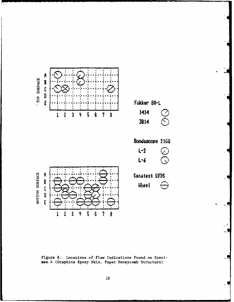
8 Locations of Flaw Indications Found on Specimen 4(Graphite Epoxy Skin, Paper Honeycomb Structure) ... ...... 18
9 Locations of Flaw Indications Found on Specimen 5(Aluminum Skin, Honeycomb Structure) .... ............ ... 19
10 Locations of Flaw Indications Found on Specimen 6(Aluminum Skin, Honeycomb Structure) .... ............ ... 20
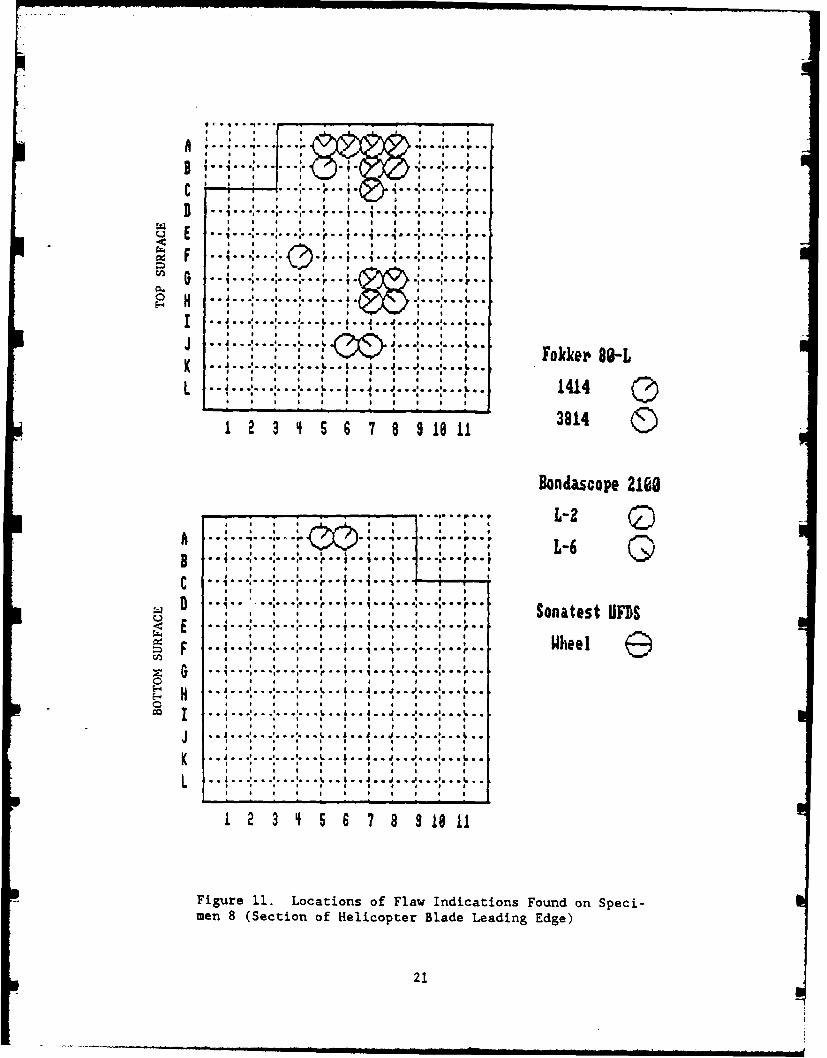
11 Locations of Flaw Indications Found on Specimen 8(Section of Helicopter Blade Leading Edge) .... ......... 21
12 Locations of Flaw Indications Found on Specimen 9(Piece of Aluminum Skin, Aluminum HoneycombStiffened Panel) ......... ...................... ... 22
13 Locations of Flaw Indications Found on Specimen 10(Helicopter Tail Rotor Blade) ..... ............... ... 23
Table
I Summary of Literature Evaluation of Ultrasonic Instru-ments for Nondestructive Inspection of Bonded Structures 4
2 Size, Thickness, and Description of the Specimens Used 12
3 Description of the Probes Used in the Laboratory Testing 14
vii

TABLE OF CONTENTS
Page
PREFACE............................... .. ...... . .. .. .. .. .. . ....
SUMMARY....................................v
LIST OF FIGURES...............................Vii
I. INTRODUCTION................................
A. Background................................B. Objective............................1C. Scope of Work .......................... 2
II. LITERATURE EVALUATION OF ULTRASONIC BOND TESTING EQUIPMENTFOR INSPECTION OF COMPOSITE AIRCRAFT STRUCTURES ........... 3
III. LA.BORATORY TESTING OF SELECTED INSTRUMENTS ............. 6
A. Instruments .......................... 6
1. BondaScope 2100........................62. UFD-S Instrument .. .................... 63. Fokker Bondtester Model 80-L .. ...............
B. Specimens. .... ....................... 8C. Testing Procedure. ... ................... 13D. Results .. ............. ............. 13E. Discussion. ............ ............. 25
IV. CONCLUSIONS AND RECOMMENDATIONS ..... ............. 26
A. Conclusions .. ............. ........... 26B. Recommendations. ... .................... 27
* APPENDICES
A Listing of Names and Manufacturers of Ultrasonic Instrumentsfor Inspection of Bonded Structures
B Ultrasonic Equipment Evaluation Form and Rating Guidelines
ix

I. INTRODUCTION
A. kgro
Advanced composite materials are finding widespread application in theconstruction of Army helicopters, ranging from the fabrication of secondarystructures to the construction of primary load-carrying airframe structures.
Composite airframe structures are fabricated by adhesively bonding the com-ponents together. During service, flaws such as debonds, delaminations, andcracks may be induced in a structure by overstress and impact. If such flawsgo undetected and are allowed to grow, they will eventually cause seriousweakening and failure of the structure. To ensure the reliability and safetyof a structure, it is therefore necessary to inspect the structure regularlyfor flaws and damages.
In the nondestructive inspection of advanced composite airframe structures,ultrasonic techniques such as through-transmission, pulse-echo, and resonanceare extensively used. Ultrasonic bond testing instruments are essential equip-ment for the inspection. A variety of ultrasonic bond testing instruments arepresently available on the market for inspection of composite structures.For determining the Army's future equipment needs to improve the accuracy andreliability of nondestructive inspection of Army advanced composite airframestructures, information on the capabilities and limitations of these commercialultrasonic instruments is prerequisite. The goal of the program reportedherein was to obtain updated information on the capabilities of commerciallyavailable ultrasonic bond testing equipment.
B. Qbjective
The specific objective of the program was to identify and evaluate commer-cially available ultrasonic bond testing instruments for inspection of adhe-sively bonded composite airframe structures. To effectively utilize Army funds,the objective of the program was to be accomplished by expanding an Air Forceprogram entitled "Through-Transmission/Pulse-Echo Ultrasonic EquipmentEvaluation."*
*The Air Force program was conducted for the Nondestructive Inspection ProgramOffice, Service Engineering Division, Directorate of Material Management andEngineering Inspection, San Antonio Air Logistics Center, Kelly Air Force Base,San Antonio, Texas 78241, as a special task by the Nondestructive TestingInformation Analysis Center (NTIAC) under Contract No. DLA 900-84-C-0910, CLINOOOBC. The program was completed in September 1987, and a copy of the finalreport can be obtained from the Defense Technical Information Center, CameronStation, Alexandria, Virginia 22314.
1

C. g of .LW2.rk
The scope of work of the subject program included:
(1) Literature evaluation of the capabilities of commercial ultrasonicbond testing instruments identified during-the Air Force program.The evaluation was to be based solely on the information available inthe literature collected during the Air Force program.
(2) Laboratory testing and evaluation of three instruments selected duringthe Air Force program by using samples of composite airframe struc-tures supplied by the Army.
2
II. LITERATURE EVALUATION OF ULTRASONIC BOND TESTING EQUIPMENTFOR INSPECTION OF COMPOSITE AIRCRAFT STRUCTURES
During the course of the Air Force program, more than fifty ultrasonic bondtesting instruments were identified, as listed in Appendix A. Of these, forty-one instruments were evaluated based on the data available in the literatureincluding product brochures and catalogues obtained from equipment manufacturersor distributors. The parameters considered in the evaluation included flawsensitivity, accuracy in flaw location, dependency on operator skill, need forsurface preparation, inspection speed, repeatability and reliability of inspec-tion results, portability, maintainability, power requirements, personnelsafety, and equipment cost. The evaluation form and the rating guidelinesused are given in Appendix B. The overall findings are summarized in Table i.Because of inadequate information, some of the parameters used such as accuracy,sensitivity, repeatability, and reliability were difficult to determine quan-titatively. As a result, the evaluation was qualitative and, in sbme cases,incomplete. Therefore, no attempts were made to rank the instruments.
The majority (32 out of 41) of the evaluated instruments were based on theconventional pulse-echo/through-transmission techniques. Of the remainingnonconventional ultrasonic instruments (9 out of 41), six were based on reso-nance techniques, two on the acousto-ultrasonic technique, and one on the shadowtechnique (see Section III.A.2). All the instruments required some degree ofoperator skill and experience, particularly in interpretation of the detectedsignals.
Most of the instruments (33 out of 41) used sensors (or probes) which require aliquid couplant such as light machine oil or water to transmit ultrasonic energythrough the contacting interfaces between the probe and the part under inspec-tion. Several instruments (8 out of 41) were operated with dry-coupled probeswhich do not require a liquid couplant. The dry-coupled probes use a pliableand resilient material such as rubber to transfer ultrasonic energy from thep-czoelectric crystal to the part under inspection and vice versa. The couplingstate of both the liquid-coupled and dry-coupled probes influences the inspec-tion results. Therefore, to obtain repeatable results, uniform and consistentcoupling of the probes is required.
Almost all the instruments (38 out of 41) evaluated required a smooth and cleansurface of the part for inspection. However, substantial surface preparationsuch as removing paint on the part is not generally required. In addition,most of the instruments (36 out of 41) were operable in field environmentalconditions. Except for highly sophisticated and automatic instruments and someinstruments operated with a wheel-type probe, the inspection speed of theinstruments was slow (32 out of 41).
With the recent advancements in semiconductor and computer technologies, ultra-sonic NDT instruments have been undergoing a transition from analog and manualtypes to digital, automatic, and computer-controlled types. Most of theinstruments for which information was gathered (34 out of 41) incorporated therecent, state- of-the-art electronic design technologies partially or totally.At present, almost all instruments (37 out of 41) are equipped with visualand/or audible alarm to aid in flaw detection. The majority of the instruments
3

4 2 Z3 2 ! 2 !!444 Z42 2
.0 0 0. .0 0. .0 0. .0 0 0. .0 0. .0 0. .0 0. .0 0. .0 0 0 . . 0 0 0 . 0 0 . . 0 0 .
.2 -
0 0
:F j0j 00 .0 .0 . . . 0 .1,0 1,1.sI 3 3 -
r C * i S IO t g 0 33 ~ 1 ~ V 3 3 3
o 0
oC 9 0 cc0 G . .0.00
00
0, .0 , w o
0.a -. v 0 0 .0 .0 .0 .0 .0
w a
I- o 0 0 00
oo 0t '0 .000.0 .0
-00
-
o: a mm .. ma a a aa a a a a aa3 ~a~
3t 3 V 2 f~ tt 2t t t tt t t t 1 1 1 2V1VV. VV
.0 00
3 m~- 3R 3 V a t t t t mv t t t t t O I V v X
g n 4 .0 0 0 . 0 0 . c. 0 . 0
m0 t m c 0 0 0 0 0 0 .
3t 3 cc 00. 0 >00. 1303 3m mt 3 t 3 3 1 V
0 o o4 o.0 W; IF - a0 a - 0 0 0 > 0 C

(32 out of 41) are modular in construction to facilitate maintenance and repair.Also, the majority of the instruments (38 out of 41) are microprocessor-con-trolled and have interfaces for communication with an external computer andperipheral devices such as a printer, a video display, or a data storage device.Some of the computer-controlled instrumentation systems (15 out of 41) havecapabilities for data acquisition, data processing, data analysis and evalua-tion, as well as documentation of the inspection. In general, microprocessor orcomputer-controlled instruments require a fair amount of operator training(2 weeks or more).
Portability of the instruments evaluated was generally high (28 out of 41).Also, about half of the instruments (23 out of 41) were battery operable (Lowin the Power Requirement column in Table 1). The operating time of the bat-teries varied with each instrument but ranged typically from 6 to 12 hours.
5
III. LABORATORY TESTING OF SELECTED INSTRUMENTS
A. Instrmants
During the Air Force program, four instruments were selected by the AirForce and evaluated in the laboratory. In accordance with the scope of work ofthe subject program, three out of these four instruments were evaluated in thelaboratory in this program. The three instruments were:
* NDT Instrument, Inc. BondaScope 2100* Sonatest UFD-S instrument* Fokker B.V. Bondtester Model 80-L
The selection of these three instruments was made based on their goodperformance during the Air Force program.
The operating principles of the three selected instruments are describedbriefly in the following paragraphs.
1. BondaScooe 2100
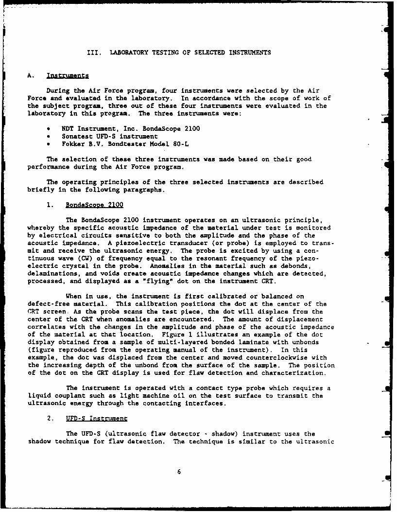
The BondaScope 2100 instrument operates on an ultrasonic principle,whereby the specific acoustic impedance of the material under test is monitoredby electrical circuits sensitive to both the amplitude and the phase of theacoustic impedance. A piezoelectric transducer (or probe) is employed to trans-mit and receive the ultrasonic energy. The probe is excited by using a con-tinuous wave (CW) of frequency equal to the resonant frequency of the piezo-electric crystal in the probe. Anomalies in the material such as debonds,delaminations, and voids create acoustic impedance changes which are detected,processed, and displayed as a "flying" dot on the instrument CRT.
When in use, the instrument is first calibrated or balanced ondefect-free material. This calibration positions the dot at the center of theCRT screen. As the probe scans the test piece, the dot will displace from thecenter of the CRT when anomalies are encountered. The amount of displacementcorrelates with the changes in the amplitude and phase of the acoustic impedanceof the material at that location. Figure 1 illustrates an example of the dotdisplay obtained from a sample of multi-layered bonded laminate with unbonds(figure reproduced from the operating manual of the instrument). In thisexample, the dot was displaced from the center and moved counterclockwise withthe increasing depth of the unbond from the surface of the sample. The positionof the dot on the CRT display is used for flaw detection and characterization.
The instrument is operated with a contact type probe which requires aliquid couplant such as light machine oil on the test surface to transmit theultrasonic energy through the contacting interfaces.
2. UFD-S Instrument
The UFD-S (ultrasonic flaw detector - shadow) instrument uses theshadow technique for flaw detection. The technique is similar to the ultrasonic
6

bon ed
air
(a) BondaScope Display of Unbonds in Laminate Shown Below
_______________3____ 4 Unbond
(b) Multi-layered Bonded Laminate with Unbonds
Figure 1. BondaScope Ultrasonic Impedance Plane Presentation for a Multi-layered Laminate
7

pulse-echo or pitch-catch method except that it relies on the ultrasonic signalredirected by the presence of a defect rather than the direct reflected signalfor flaw detection. Changes in the pattern of the received signal caused bydefects are correlated to the condition of the material under test. Morespecifically, the following three factors are used for determining the materialcondition: (1) amplitude of the received signal, (2) displacement of the start-ing point of the first half-cycle of the received signal on the time base, and(3) shape of the interference pattern. Calibration of the instrument and probealignment (distance between the transmitter and the receiver and their respec-tive angle relative to the surface of a part under inspection) by using areference sample of known condition is required prior to the inspection. Anychanges in the signal pattern exceeding the predetermined acceptance levelwould indicate a fault or flawed condition. Figure 2 shows an example of signalpattern change with increasing fault condition (from the instrument brochure).Figure 2a is the signal from a good area. The received signal shown inFigure 2b is shifted to the right and is smaller in amplitude because of a faultcondition (no specifics were given on the fault condition in the brochure). Asthe fault condition becomes more severe, the signal is shifted further to theright accompanied by a further reduction in amplitude as shown in Figure 2c.Two types of dry coupled probes are used with the instrument: a roller probeand a rubber-tip probe. Both probes do not require any liquid couplant. Theroller probe is for continuous scanning. The rubber-tip probe is for inter-mittent spot checking.
3. Fokker Bondtester Model 80-L
The Fokker Bondtester instrument is based on the principle that theresonant frequency and the electrical impedance of a piezoelectric crystalplaced on the surface of a bonded structure are dependent on the quality of thebonded joints. The shift in resonant frequency and the change in electricalimpedance of the crystal are measured and used for flaw detection and charac-terization. The instrument uses a continuous wave (CW) signal like the Bonda-Scope 2100 described above. To find the resonant frequency, however, thefrequency of the CW signal is swept in a certain range determined by the settingon the instrument. When the applied CW frequency equals the resonant frequencyof the crystal, the electrical impedance of the crystal exhibits the mostchange. Both the shift in resonant frequency (called A-Scale) and the peakchange in electrical impedance (called B-Scale) are displayed on the instrument.Since the instrument relies on relative changes, it must be calibrated prior tothe inspection by using a reference sample. An example of typical A-Scaleindications for various bond qualities is illustrated in Figure 3 (from theoperating manual of the instrument).
The crystals (or probes) used with the instrument require a liquidcoup lant.
B. Sjecimens
Ten specimens of Army composite airframe structures were used in thelaboratory testing. Figure 4 is a photograph of the samples. The sampleswere provided by the Army and were of unknown characteristics and defectconditions. The size, thickness, and description of the specimens used aregiven in Table 2.
8

~~41
I.r.obzW
:3 c
91
0
bo
144
4)
ob4.14
'cc
boQ
0 ra000
co4.

crystadisanc dIbnd bo de in d
jointoat V% bnd"
1) Onl one rbitrry LE -a indicationhon
Figure ~7i 3. Typca aBo nndse A-cl niaindonato SingBndiniuation wag ihgliel TnLoeheeats as aon
Fucto nood ualityo ainiato o
cryta iea bndd onedj10

o --2 " __ -
I L1
Figure 4. Composite Ai.rframe Structure Specimens Used in the -
Laboratory Testing
11__

Table 2
SIZE, THICKNESS, AND DESCRIPTION OF THE SPECIMENS USED
Specimen Size ThicknessNumber (inches) (inches) Descri~tion
1 10 x 10 1 Graphite epoxy skin, paper honeycombpanel
2 10 x 10 1 Fiberglass epoxy skin, paper honey-comb panel
3 4 x 4 1 Graphite epoxy skin, paper honeycombpanel
4 6.25 x 4 1 Graphite epoxy skin, paper honeycombpanel
5 6 x 6 2 Aluminum skin, honeycomb panel(a)
6 10 x 10 11/16 Aluminum skin, honeycomb panel(b)
7 12 x 7 3/4 Aluminum skin, aluminum honeycombpanel(c)
8 8 x 8 3 inch max. Section of a helicopter blade edge
9 (d) (d) Piece of aluminum skin, aluminumhoneycomb stiffened panel takenfrom an AH-l helicopter
10 (e) Helicopter tail rotor blade
(a) Nonmetallic honeycomb core of an unknown material type.
(b) The honeycomb was not visible because the sides of the specimen were sealedwith a sealant.
(c) The top and bottom surfaces of the specimen were rough. The top surface(shown in Figure 4) had wrinkles in an irregular fashion. The bottomsurface was embossed in a diamond shape pattern.
(d) About 11 inches wide. Each leg of the specimen was approximately 5 incheslong and 2 inches wide. The specimen leg was stiffened with honeycombstringer approximately 0.25 inches high, 0.5 inches wide, and 4.5 incheslong.
(e) Approximately 24 inches long; the blade section was 5.25 inches wide.
12
K1
C. Testing Procedure
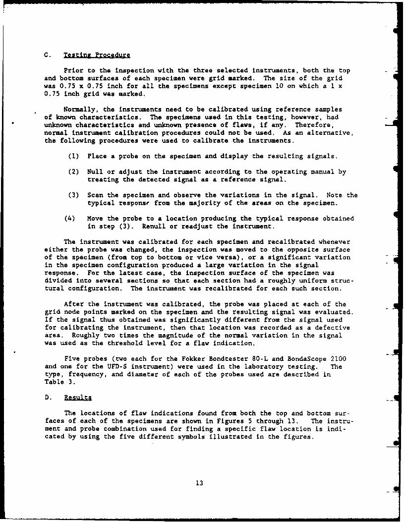
Prior to the inspection with the three selected instruments, both the topand bottom surfaces of each specimen were grid marked. The size of the gridwas 0.75 x 0.75 inch for all the specimens except specimen 10 on which a 1 x0.75 inch grid was marked.
Normally, the instruments need to be calibrated using reference samplesof known characteristics. The specimens used in this testing, however, hadunknown characteristics and unknown presence of flaws, if any. Therefore,normal instrument calibration procedures could not be used. As an alternative,the following procedures were used to calibrate the instruments.
(1) Place a probe on the specimen and display the resulting signals.
(2) Null or adjust the instrument according to the operating manual bytreating the detected signal as a reference signal.
(3) Scan the specimen and observe the variations in the signal. Note thetypical response from the majority of the areas on the specimen.
(4) Move the probe to a location producing the typical response obtainedin step (3). Renull or readjust the instrument.
The instrument was calibrated for each specimen and recalibrated whenevereither the probe was changed, the inspection was moved to the opposite surfaceof the specimen (from top to bottom or vice versa), or a significant variationin the specimen configuration produced a large variation in the signalresponse. For the latest case, the inspection surface of the specimen wasdivided into several sections so that each section had a roughly uniform struc-tural configuration. The instrument was recalibrated for each such section.
After the instrument was calibrated, the probe was placed at each of thegrid node points marked on the specimen and the resulting signal was evaluated.If the signal thus obtained was significantly different from the signal usedfor calibrating the instrument, then that location was recorded as a defectivearea. Roughly two times the magnitude of the normal variation in the signalwas used as the threshold level for a flaw indication.
Five probes (two each for the Fokker Bondtester 80-L and BondaScope 2100and one for the UFD-S instrument) were used in the laboratory testing. Thetype, frequency, and diameter of each of the probes used are described inTable 3.
D. Results
The locations of flaw indications found from both the top and bottom sur-faces of each of the specimens are shown in Figures 5 through 13. The instru-ment and probe combination used for finding a specific flaw location is indi-cated by using the five different symbols illustrated in the figures.
13

Table 3
DESCRIPTION OF THE PROBES USED IN THE LABORATORY TESTING
ProbeProbe Probe Diameter
Instrument TI=e Frequencv (inch)
Fokker Bondtester 1414 Not Available* 1/480-L 3814 Not Available* -BondaScope 2100 L2 260 - 300 kHz 1/4
L6 355 - 385 kHz 1/8
UFD-S Wheel (Roller) 1.25 MHz 1
*Approximately 350 kHz.
On specimen 1 (graphite epoxy skin, paper honeycomb structure, 10 x 10 x 1inches). four flaw locations were found as illustrated in Figure 5. One loca-tion (M-ll on the top surface) was detected with both the Fokker BondtesterModel 80-L and the BondaScope 2100. The rest of the locations were detectedwith the Sonatest UFD-S.
On specimen 2 (fiberglass epoxy skin, paper honeycomb structure, 10 x 10 x1 inches), two flaw locations were detected on the top surface as described inFigure 6. These locations were found with the Fokker Bondtester Model 80-L andthe 3814 probe combination only. No flaw indications were detected with theother combinations of the instrument and probe.
Locations of flaw indications found on specimen 3 (graphite epoxy skin,paper honeycomb structure, 4 x 4 x 1 inches) are illustrated in Figure 7.They were observed at 13 locations on the top surface and 4 locations on thebottom surface. Nine locations exhibited flaw indications by more than oneinstrument-probe combination: eight (locations C-l, C-2, C-5, D-l, D-2, E-1,E-4, and E-5) on the top surface and one (location E-4) on the bottom surfaceof the specimen.
Locations of flaw indications found on specimen 4 (graphite epoxy skin,paper honeycomb structure, 6.25 x 4 x 1 inches) are shown in Figure 8. Of thesix locations detected on the top surface, two (locations C-2 and C-8) showedflow indications by more than one instrument-probe combination. No flaw indi-cations were observed with the UFD-S instrument on the top surface of thespecimen. On the bottom surface, a total of 18 locations exhibited flaw indi-cations; of these, only two locations (C-2 and C-6) were found with more thanone instrument-probe combination. Most of the flaw indications on the bottomsurface were detected with the UFD-S instrument.
Figure 9 shows the locations of flaw indications found on specimen 5(aluminum skin, honeycomb structure, 6 x 6 x 2 inches). A total of 13 flawindications were found on the top surface; of these, five (locations A-7, C-5,
14

_ _ . J L... ...... ....
E 1-4.. ... . ., . . . ...... - , ..... . *
F 4-
B -
0 . . . . C
F •*o••*+ e I * S S SI e , S e T ° *
* S i I S m
CIi m e * s * e *• * | *. o
E ' ' i*i : .:J -- -- : .-: "' ' I"• " ' + " "e'"* i S S S
-K *.........&-'--..J
* I I S S SiS
_____ ____ ____ _~ 514.14
1 23 4 5 6789 98111 2 13 081.. e .,Q
..4................:................Uhe
o Bo! a coe e 2109
* C I I I I * I S S I
........... ......... .............
l S I l I , * , m
a * i m m * * * * ,
........... ....... ~.. '•I . .J .. Ji Ie ... .11, ii e le
I I I I I I S S I I IL " I ,"" ~:........:' *'" *" '" {: ""....."' ", "I I S S
. . . . . . . .. . .. J... ...... .... FktP 0-K "".............. ".. ... I
* S i S I S I i i
L ....... e
* I S I S i , l I Ii S
1 2 3 4 5 6 7 8 9 19 11 12 13
Figure 5. Locations of Flaw Indications Found on Speci-men 1 (Graphite Epoxy Skin, Paper Honeycomb Structure)
15

A .. ....... Q
a. . . - a a ' i, S*Q l e°e a a S S So Sil S * Sl e S °
1 2 6 6 7 i 1 is 1 LI
o o nd ao 2169
i ~ ~ ~ ~ - 0
. al e . a .~ a S So Se Se So a a apole
G ~L-.G• .
S .. i •.. I... .. .
E 4-.-. .''".. .. .. . .""h"ee'" 14"
I . Iz --:--r ... . ., -- -I -- ,-- . ....... --- --. -:-
L-
a1 3 I 12 1
Fiur "'6:.. ain of F"l"" a" Indcaton Found",Sp;ci
. . . . . . . . .. Honeycomb Sre-
S a a S S I • S • e a a a
tz. . . . . . . . .. . 3 S 14*
kn~ F 26
i S S S i a S • 5 5 5 5 5
-*,--1- 4- '--,.. .. aa-'
I i*~* a
N e .. .................... .... H eeN i. .:**~--- -I--I- a S a
-4--4-- '-{ -7-8-9611 21
Fiur 6. Locaions of Flaw Indicain on nSeime Fbrls Epx S i Pae oecmbSrcue
! i 16

A I I
B- r . Fokker 80-L
, 1414
1 2 3 4 S]ondascope 2168
L-2 C
L-6 Q
A .. a Sonatest UFDS
at a -:a-- a.--,---. Wheel &I ...... .
a a a l la aa
Figure 7. Locations of Flaw Indications Found on Speci-men 3 (Graphite Epoxy Skin, Paper Honeycomb Structure)
17
A e I a oo
1 2 S a 7 a
Boda p 2 10le
D W a I
E - a a a a Fokker80-1a e a al a Sl a el * o ale
I 2 3 4 S 6 7 8 14141814
B8nclascope 21G
L-2 C
a I a a IA................Sonatest UFD)S
", " , a
S2 3 4 587 ?8
Figure 8. Locations of Flaw IndicaClons Found on Speci-men 4 (Graphite Epoxy Skin, Paper Honeycomb Structure)
18

1 . . . . . . t . 1 .• . . . . . .
- , * , ,a a , ,* , * *.
a~ -S 4
A I I I a
a a I I i I
Boescp 216
I I a
0 :F -8-- . -,.................. .,.,a .
II I I
L-2 0lSonate .1FD .
a a a II
"" " . "" " " L -.I ,
Wheel
F aure I Imn5(uiuSi... .. ....... r.. .t..
a I S SS I a I a I
I a a , I a S I
Figure 9. Locations of Flaw Indications Found on Speci-men 5 (Aluminum Skin, Honeycomb Structure)
19

... ... .. . .. . I I I a i.
B
K a Fokkei 8 9-L
* S
I a. 3 ' 5 6 7 8 916 111213
Bondascope 219
L-2 0_ _ _ _ _ _ _L- Q
* **, * S. S.
....... sonatest UMD
0 * 3 -81
- . . ... - -
me 6 (Aluminum Skin Hoecm Structure
20
* I_ L ._I _ I _ I II I . i i i. . ..
,. . ...... ...! . . . .-- " " J -" . .
I .
........ ..U 1 I lI O
e
l l
1 2 II S I I I I 1 I
a IlI I I I I I1 I
i ] ej
o
ond asco e 2169
to Ila l l O Il g I a I I i l Ile . II I I I i I I I~ F . . .. ,.,
F I I Ij
I 0 t ! I II I I I I
I t I I I I
I . . . I . . . . I. . I . I Ili l l I 1 II I I I I I
.. ... ',. .. . "".'' '",, , ,....
I I I I I I i I8 -* I I i I I IIII I I I
E-44
-- . .. .. . . . .
1 23 4 S 7 8 9 1611 31
I i L o In
men* 8 ScioofHeiote ldeLain tdetlD
a iI I I I I I
I tI I I
A .-. ~ I I I I •ie
.G
I * " ** /* * I lI I IJ'
e* I1"
I III I I I I I
I Ii i iI I I I I Io a e t U D
*. I I a II I I I I I I I I I
.... J........... h e :,. , , , , , a , , ,
I I i i I I I I I I
l - I I I
1 31 1 6 6 7 ...916 .
Figure 11. Locations of Flaw Indications Found on Speci-men 8 (Section of Helicopter Blade Leading Edge)
21

a I _ a aI I I II I i I I I I I a n , , , , . =
a I I i
a a a I a * a
ae q , a a a l e l a a a aelo e~olS II a a a a
A
B ........... .. .. ... .... -....
o , IO,. O OC . -. . . .. I . .. .. . . .
_____________________________Fokker 89-L
12 34 58 7 8 91611 1414
3814
Bondascope 2190
L-2 0
A....... ... ..........
o~Whe Ie lli
R D . . . .. . ' .. . . uF Ie
1 1 . .
a a a a Il * a I al e A Q p ,
' I I .a
UIe
i i I a i a l a a 9
1 2 3 11 S 6 7 8 9 10 11
Figure 12. Locations of Flaw Indications Found on Speci-men 9 (Piece of Aluminum Skin, Aluminum HoneycombStiffened Panel)
22

aEa
1 2 3 '1 5 6 7 8 1 11 1213 14 15'16 3814
Bondascope 2196
L-6
Sonatest UFDS
w Wheel
1 2 3 q S 6 7 9 91811 12 13 14 15 16
Figure 13. Locations of Flaw Indications Found on Speci-men 10 (Helicopter Tail Rotor Blade)
23

E-7, H-i, and H-8) were detected with more than one instrument-probe combina-tion. On the bottom surface, 13 flaw indications were also found; of these,three (locations C-3, D-4, and E-5) were detected with more than one instrument-probe combination. The locations of flaw indications shown in Figure 9 werefound by using the Fokker Bondtester Model 80-L and BondaScope 2100. No indica-tions were detected with the UFD-S instrument because of too much signal varia-tions and resulting difficulty in calibrating the instrument.
Figure 10 shows the locacions of flaw indications found on specimen 6(aluminum skin, honeycomb structure, 10 x 10 x 11/16 inches). On the topsurface, a total of 64 locations showed flaw indications; 19 of these weredetected with more than one instrument-probe combination. On the bottom sur-face, a total of 28 locations showed flaw indications; 15 of these were detectedwith more than one instrument-probe combination.
On specimen 7 (aluminum skin, aluminum honeycomb structure, 12 x 7 x 3/4inches), no meaningful flaw locations were detectable with the instrumentsused. Because of the rough surface conditions of the specimen, it was verydifficult to make and maintain proper coupling of the probe to the specimen.Consequently, the signal varied widely and it was very difficult to calibratethe instruments and to discern flaw indications.
Figure 11 shows the locations of flaw indications found on specimen 8 (asection of helicopter blade leading edge). Because of'the change in thecurvature on the surface and the change in the thickness, recalibration of theinstruments was required for inspecting different regions of the specimen. Onthe top surface, 15 locations of flaw indications were found with the FokkerBondtester Model 80-L and the BondaScope 2100. No flaw indications were foundwith the UFD-S instrument. Of these locations, 10 exhibited flaw indicationsfor more than one instrument-probe combination. On the bottom surface, onlytwo locations showed flaw indications which were detected with the FokkerBondtester Model 80-L and probe 1414 combination. The surface curvature in thearea where columns 9 through 11 were marked was too large to maintain a propercoupling of the probes for the Fokker Bondtester Model 80-L and the Bonda-Scope 2100. Therefore, the area was not inspectable with the Fokker Bondtesterand the BondaScope.
Figure 12 shows the locations of flaw indications found on specimen 9 (acutout piece of corroded aluminum skin, aluminum honeycomb stiffened panel).As shown, three locations on the top surface and four locations on the bottomsurface were detected with the Fokker Bondtester Model 80-L and the BondaScope.The specimen was not inspectable with the UFD-S instrument because the wheelprobe was too large for scanning the specimen and the instrument was difficultto calibrate.
Figure 13 shows the locations of flaw indications found on specimen 10 (ahelicopter tail rotor blade). Because of the change in specimen configuration,recalibration of the instruments was required for each row marked on the speci-men. A total of 11 locations on the top surface and 9 locations on the bottomsurface exhibited flaw indications. Most of these flaw indications weredetected with the UFD-S instrument. With the BondaScope 2100, only one location(location B-i on the top surface) exhibited a flaw indication. With the FokkerBondtester Model 80-L, three locations were detected on each surface for a
24

total of six locations. It was also observed that the painted area (dark area*in the picture of specimen 10 shown in Figure 4) exhibited significantly dif-
ferent response from the unpainted area (bright area in the picture of thespecimen shown in Figure 4) on both the Fokker Bondtester and the Bonda-
• ,Scope 2100. This indicated that the paint on the specimen could significantlyaffect the instrument response. With the UFD-S instrument, no significantdifference in response was observed between the painted and unpainted areas.
E. Discussin
Generally speaking, calibration and operation training for both the FokkerBondtester Model 80-L and the BondaScope 2100 can be accomplished within a fewhours. Both instruments were sensitive to the variation in the coupling statebetween the probe and the specimen. Both instruments were designed for spotchecking and therefore inspections with these instruments were slow.
On.the other hand, the UFD-S instrument was difficult to calibrate, parti-cularly in the absence of reference samples of known characteristics. There-fore, the operator must have extensive experience in calibration and operationof the instrument. The wheel (or roller) probe allowed continuous scanning ofthe specimen and consequently the inspection could be done within a short time.The fixture for holding the two wheel probes (one for transmitting and theother for receiving) in place, which was provided to us with the instrument forthe laboratory evaluation, did not hold the probes well and thus needed furtherimprovement.
Locations of flaw indications found on the specimen varied depending onthe instrument-probe combination employed. The fact that only a small per-centage of the flaw indications found was detected with more than oneinstrument-probe combination suggests that each instrument-probe combination hasdifferent sensitivity and/or different areas of application. To evaluate theaccuracy and flaw sensitivity of each of the five instrument-probe combinationsused in the laboratory testing, detailed characterization of the specimens isrequired, perhaps using other NDE techniques such as ultrasonic C-scan, x-ray,or neutron radiography, or destructive sectioning. Characterization of theflaws in these specimens was beyond the scope of the present program.
All three instruments were difficult to use for inspection of specimen 7,which had a rough surface. This indicates that their applicability is limitedto parts having smooth surfaces. In addition, surface curvature was found tolimit the applicability of both the Fokker Bondtester and the BondaScope. Thepaint on the specimen significantly affected the response of both the FokkerBondtester Model 80-L and the BondaScope, indicating that variations in paintthickness may limit the accuracy of these instruments.
25
L
IV. CONCLUSIONS AND RECOMMENDATIONS
A. Conclusions
Instruments Available
(1) More than fifty commercial ultrasonic instruments are available fornondestructive inspection of bonded aircraft structures. (See Appendix A for alist of 58 such instruments.) The majority of these instruments are conven-tional ultrasonic flaw detectors based on pulse-echo and through-transmissiontechniques. The rest of the instruments, which comprise a small minority, arebased on nonconventional techniques including the resonance technique, theshadow technique, and the acousto-ultrasonic technique.
Literature Evaluation
(2) Most of the 41 instruments evaluated in this study use sensors (orprobes) which require a liquid couplant such as light machine oil or water totransmit ultrasonic energy through the contacting interfaces between the probeand the part under inspection. Several instruments are operated with dry-coupled probes which do not require a liquid couplant. The dry-coupled probesuse a pliable and resilient material such as rubber to transfer ultrasonicenergy from the piezoelectric crystal to the part under inspection and viceversa. The degree of coupling of both the liquid-coupled and dry-coupled probesinfluences the inspection results. Therefore, to obtain repeatable results,uniform and consistent coupling of the probes is required.
(3) The trend in ultrasonic instruments is toward digital, automatic, andcomputer-controlled instruments. The majority of the commercial instrumentsare microprocessor-controlled with interfaces for communication with otherdevices such as an external computer, a printer, a recorder, or a video display.Also, the majority of the instruments are modular in construction to facilitatemaintenance and repair. In addition, almost all instruments are equipped withvisual and/or audible alarms to aid in flaw detection.
(4) Almost all the instruments evaluated require a smooth and clean
surface of the part for inspection. However, substantial surface preparationsuch as removing paint on the part is not generally required. In addition,most of the instruments are operable in field environmental conditions. Exceptfor highly sophisticated and automatic instruments and some instruments operatedwith a wheel type probe, the inspection speeds of the instruments are generallyslow. The portability of the instruments is generally high. Also, about 50% ofthe instruments are battery operable. The operating time of the batteriesvaries with each instrument but ranges typically from 6 to 12 hours. Theequipment cost varies over a wide range from several thousand dollars to over aquarter of million dollars depending on the degree of sophistication andautomation.
Laboratory Evaluation
(5) Three instruments, the Fokker Bondtester Model 80-L, BondaScope2100, and UFD-S, were evaluated in the laboratory using a total of ten specimens
26
of composite airframe structures supplied by the U.S. Army. The specimens hadunknown characteristics and flaw conditions. Based on observations made duringthe laboratory testing, the following conclusions can be drawn:
(a) Both the Fokker Bondtester Model 80-L and the BondaScope 2100were easy to calibrate and easy to use, whereas the UFD-S instrument wasdifficult to set up and calibrate without the use of reference samples of knowncharacteristics.
(b) Both the Fokker Bondtester and the BondaScope were designedfor spot checking, whereas the UFD-S instrument allowed continuous scanning ofthe specimen.
(c) Probes for both the Fokker Bondtester and the BondaScope arecoupled to the specimen with a liquid couplant, while the wheel probe for theUFD-S instrument does not require any liquid couplant.
(d) All three instruments were limited to inspection of smooth-surfaced specimens.
(e) Both the Fokker Bondtester and the BondaScope were difficult touse on a highly curved surface. This limitation is due to the difficulty inmaintaining proper coupling of the probe to the curved surface.
(f) Variations in paint thickness might limit the accuracy of theinspection results.
(g) All three instruments are suitable for routine field inspectionof composite airframe structures.
(h) Because the specimens used had unknown characteristics and flawconditions, the accuracy and flaw sensitivity of the three instruments could notbe evaluated.
B. Recommendations
(1) Characterization of the specimens using independent methods isrecommended in order to evaluate the accuracy and flaw sensitivity of the threeinstruments.
(2) Because of the availability of improved ultrasonic equipment, evalu-ation of the ultrasonic inspection equipment currently used in the Army isrecommended to determine the need for upgrading equipment to better achieve theArmy's aircraft maintenance goals.
27

41A
'The listing contained in this Appendix was generated during the literatureevaluation performed under the Air Force program (a** Paragraph I. S andSection 11).

No. Equipment Name Manufacturer
1. Ultra Image III Ultra Image International
2. Acousto-Ultrasonics Instrumentation Physical Acoustics Corp.System
3. ultisonic/PC California Data Corp.
4. UD-S Ultrasonic Flaw Detector Sonatest
5. Zipscan 2 SGS Sonomatic Ltd.
6. Sparta TTU-90 Sparta Technology
7. USIP 12 Ultrasonic Flaw Detector Krautkramer Branson
8. USIP 11 Ultrasonic Flaw Detector Krautkramer Branson
9. PARIS (Portable Automated Remote Sigma Research, Inc.Inspection System)
10. SDL-1000 Ultrasonic Imaging System Sigma Research, Inc.
11. Sigma Series 2000 Ultrasonic Imaging Sigma Research, Inc.System
12. USD-1 Krautkramer Branson
13. Fokker Bondtester Model 80 L Fokker B.V.
14. M-Series Ultrasonic Instrument Nortec/Metrotek
15. NDT-132 Portable Ultrasonic NDT Nortec/MetrotekInstrument
16. AET Model 206AU Acousto-Ultrasonic Acoustic Emission TechnologyInstrument Corp.
17. NovaScope 3000 Automation/Sperry
18. NovaScope 2000 Automation/Sperry
19. BondaScope 2100 NDT Instruments, Inc.
20. Bondtester 210 NDT Instruments, Inc.
21. S-lA Sondicator Ultrasonic Test Instrument Automation/Sperry
29

No. Equi~went Name Manufacturer
22. S-2B Sondicator Ultrasonic Test Instrument Automation/Sperry
23. PS-710B Pulse Ultrasonic Test Unit Magnafluz Corp.
24. FX-3 Ultrasonic Flaw Detector Magnaflux Corp.
25. FX-5 Ultrasonic Flaw Detector Magnaflux Corp.
26. FX-7 Ultrasonic Flaw Detector Magnaflux Corp.
27. Echograph 1150 Ultrasonic Instrument Karl DeutschSystem
28. Echograph 1030 Portable Modular Karl DeutschUltrasonic Flaw Detector
29. Echograph 1030-QUASCO Portable Ultrasonic Karl DeutschQuality Assurance System
30. EchoSraph Series 10 Portable Ultrasonic Karl Deutsch
Flaw Detector
31. Echograph Series 20 Portable Ultrasonic Karl DeutschFlaw Detector
32. Nanoscope 412 Ultrasonic law Detector Erdman Instruments Inc.
33. Epoch 2002 Flaw Detector Panametrics
34. 5052UA Ultrasonic Analyzer Panametrics
35. 5055UA Ultrasonic Analyzer Panametrics
36. TenEleven SG Flaw Detector Baugh & Weedon Ltd.
37. PA1020 Ultrasonic Flaw Detector Baugh & Weedon Ltd.
38. MIA 3000 Structural Integrity Monitor Inspection Instruments Ltd.
39. USL 33 Ultrasonic Flaw Detector Krautkramer Branson
40. USL 48 Ultrasonic Flaw Detector Digital Krautkramer BransonThickness Instrument
41. USM 3 Large Screen Ultrasonic Flaw Detector Krautkramer Branson
42. USM 3S Large Screen Ultrasonic Flaw Detector Krautkramer 3ranson
30

No. Equioment Name Manufacturer
43. Intraspect 98 Ultrasonic Imaging System Combustion Engineering
44. KB-6000 Ultrasonic Instrumentation Krautkramer BransonSystem
45. QC-2000 Reflectoscope Automation/Sperry
46. QC-400 Reflect oscope Automation/Sperry
47. M-90 Reflectoscope Automation/Sperry
48. S-80 Reflectoscope Automation/ Sperry
49. CM 2000 Squirter Ultrasonic Scanning Custom Machine Inc.System
50. MBS-8000 Computer Controlled Ultrasonic MATEC Instruments Inc.Testing System
51. NDT-150 Ultrasonic Inspection System Nortec/Metrotek
52. NDT-131D Digital Ultrascope Nortec/Metrotek
53. 1712A Computerized Ultrasonic Instrument Systems Research Lab., Inc.
54. AX-8000 Integrity Tester American NDT. Inc.
55. FD-700 Ultrasonic Flaw Detector Mitsubishi Electric Corp.
56. Mark IV Ultrasonic Flaw Detector Sonic Instruments Inc.
57. ARIS (Automated Realtime Inspection Southwest Research InstituteSystem)
58. ABE (Advanced Bond Evaluator) United Western Tech., Corp.
31

APPEDX B
AND RATDG GU3[DZINlhS*
*Soo Table 1.

EquimentNameULTRASONIC E-QUIPMMIT EVALUATION FORM
-"quipment Name:
M.anufacturer
3ased on Th --Tranaission/Pulse-Echo Tech. ( )R Resonance Tech. C )
Maximum Output Voltage of the Pulser : Spike, Square Wave .ulse
Receiver Gain ., Dynamic Range d3, Freq. Range ___z_ _
Flaw SensitivityFlaw Type : Delaminations, Voids, Unbonds/Debonds, Subsurface DamageF.aw Location : Near Surface. Sub-surfaceFlaw Size :
Accuracy in Locating a Flaw : Position , Depth
Dependency on Operator Skill :Setup , Procedure , Interpretation
Need of Surface Preparation , Need of Couplant .... __
Sensitivity to Enviromental Conditions:Temp. - , Humidity - , Light - , Shock and Vibration
Inspection Speed :
Repeatability/Reliability of Inspection Results
Availability of Recorder Interface
Cost of Inspection (Including supplies and consumables)
Portability of Equipment :_Overall Weight
Maintainability of Equipment:Modular Construction , Internal Diagnosis Capability _
Power Requi:-ment :
Personnel Safety
Equipment Cost :
Ability to AutomateAdaptation/Modification Cost for Automation
Remarks
33

RATING GUDELINES
1. Flaw Sensitivity
This rating pertains to the detectability of flaws of various types, sizes.and depths in a component.- "'Low" ratings refer to the case where thedetectabilit7 is limited to flaws of a few specific types and a large size (1inch or larger in diameter). and those located near the accessible surface."High" ratings refer to the case where the detectability is good for variousflaw t7pes of small size (0.25 inch or smaller in diameter) throughout thethickness of the component. "Moderate" ratings are for the intermediatedetectability.
2. Accuracy in Locating a ?law
This rating pertains to the accuracy and the resolution in determining thespatial position of a flaw in a component.
3. Dependency on Operator Skill
This relates to the training and skill required by the operator to conductthe inspection. "Low" ratings refer to minimal training (two days or less) andtechnical knowledge (high school graduation or equivalent experience)requirements. "High" ratings refer to the case in which a two-week or moretraining and a high level of technical knowledge (university graduation orequivalent experience) are required. "Moderate" ratings are for those caseswhich require training and technical knowledge intermediate between the "Low"and "High" ratings.
4. Need of Surface Preparation
This rating measures the amount of surface preparation required in theregion to be inspected. "Low" ratings refer to the case where little or nopreparation is required other than wiping the surface to remove loose foreignmaterial such as dirt. "Moderate" ratings refer to the case where all foreignmaterial adhered to the surface such as greaseoil or dirt must be removed anda clean surface is required. "High" ratings refers to the case where asubstantial surface preparation such as removing paint is required.
5. Sensitivity to Environmental Conditions
This relates to the influence of field environmental conditions (temper-ature, humidity, light, shock, vibration, and noise) on the operation of theequipment and performing the inspection. "Low" ratings refer to the case wherethe equipment is adequate for use in the field condition. "Moderate" is forthe case where the equipment is marginal for use in the field condition."High" is assigned to the equipment whose use is limited to the laboratorycondition.
34

6. Inspection Speed
This relates to the speed of inspection. 'Low" ratings are assigned if theinspection is done manually. "Moderate" ratings are assigned if the inspectionis done manually with the use of a mechanical device such as yoke whichfacilitates the inspection. "High" ratings are assigned if the inspection isdone by using a mechanical or electrical scanning device.
7. Repeatability/Reliability of Inspection Results
This rating pertains to the repeatability (or reproducibility) and the reli-ability of the inspection results. This is intended to identify the degree ofvariation in inspection results from day to day operation and from operator tooperator. 'Low" ratings are assigned if the inspection relies heavily on thesubjective judgement of the operator and requires a high degree of operatorinteraction with the inspection process and operator's attention to detail."Moderate" ratings are assigned if the equipment is provided with featuressuch as visual or audible alarm to allow objective judgement of the operatorand the dependence of the inspection results on the operator is low. "High"ratings are assigned if the equipment requires little or no operator'sjudgement.
8. Availability of Recorder Interface
This rating relates to the availability of outputs for recording inspectionresults such as amplitude, thickness, distance, or logic (yes or no; on or off)outputs. "Low" ratings are assigned if no recording output is available."Moderate" ratings are assigned if any of the following outputs ia available;amplitude, thickness, distance, or logic. "High" ratings are assigned if allof the above outputs and A-scan output are available.
9. Portability of Equipment
This relates to the easiness in transporting the equipment by hand. "High"ratings are assigned if the equipment is equal to or less than 30 lbs. "Low"ratings are assigned if the overall weight of the equipment is over 200 lbs orthe equipment has a component weighing more than 50 lbs. "Moderate" ratingsare assigned if the overall weight of the equipment is no more than 200 lbs andno component exceeds 50 lbs.
10 Maintainability of Equipment
This relates to the easiness in maintaining the equipment including repairand calibration. "High" ratings are assigned if the equipment consists ofeasily exchangeable plug-in modules or has internal diagnosis capability."Moderate" ratings are assigned if the equipment can be diagnosed with standardtesting device such as an oscilloscope and can be repaired and calibrated atuser's facility in the Air Force. "Low" ratings are assigned if the equipmentrequires a special testing instrument or must be maintained at the manufac-turer's facility.
35

11. Power Requirement
This rating measures the power required to operate the equipment and toconduct inspections. "Low" is assigned for power requirements which can befullfilled with batteries. "Moderate" refers to a power requirement of a fewhundred watts which could be obtained from a portable generator. "High" refersto a requirement of an electrical power line.
12. Personnel Safety
This rating measures the relative amount of precaution required inoperating the equipment during the inspection to protect inspection personneland other personnel nearby.
13. Equipment Cost
This rating pertains to the cost of the basic equipment excluding periperalequipment. 'Low" is assigned if the equipment is equal to or less than$10,000. "Moderate" is assigned if the equipment is above $10,000 and equal toor less than $30,000. 'High" is assigned if the equipment is above $30,000.
14. Ability to Automate
This rating refers to the capability of the equipment for automaticinspection. "Automated" is assigned if the equipment is already automated."High" is assigned if the equipment is controllable using a microprocessor or acomputer. "Moderate" is assigned if the equipment is manually controlled butcan provide a digital output for data acquisition , process, and analysis usinga computer. 'Low" is assigned if the equipment is manually controlled andprovides an analog output.
36

DISTRIBUTION LIST
No. ofCopies To
I Office of the Under Secretary of Defense for Research and Engineering,The Pentagon, Washington, DC 20301
Commander, U.S. Army Laboratory Commahd, 2800 Powder Mill Road, Adelphi,MD 20783-1145
1 ATTN: AMSLC-IM-TL
Commander, Defense Technical Information Center, Cameron Station, Building 5,5010 Duke Street, Alexandria, VA 22304-6145
2 ATTN: DTIC-FDAC
I Metals and Ceramics Information Center, Battelle Columbus Laboratories,505 King Avenue, Columbus, OH 43201
Commander, Army Research Office, P.O. Box 12211, Research Triangle Park,NC 27709-2211
I ATTN: Information Processing Office
Commander, U.S. Army Materiel Command, 5001 Eisenhower Avenue,Alexandria, VA 22333
1 ATTN: AMCLD
Commander, U.S. Army Materiel Systems Analysis Activity,Aberdeen Proving Ground, MD 21005
1 ATTN: AMXSY-MP, H. Cohen
Commander, U.S. Army Electronics Research and Development Command,Fort Monmouth, NJ 07703
1 ATTN: AMDSD-L1 AMDSD-E
Commander, U.S. Army Missile Command, Redstone Scientific Information Center,Redstone Arsenal, AL 35898-5241
I ATTN: AMSMI-RKP, J. Wright, Bldg. 7574I AMSMI-RD-CS-R/ILL Open Lit1 AMSMI-RLM
Commander, U.S. Army Armament, Munitions and Chemical Command, Dover, NJ 078012 ATTN: Technical LibraryI AMDAR-LCA, Mr. Harry E. Pebly, Jr., PLASTEC, Director
Commander, U.S. Army Natick Research, Development, and Engineering Center,Natick, MA 01760
1 ATTN: Technical Library
Commander, U.S. Army Satellite Communications Agency, Fort Monmouth, NJ 077031 ATTN: Technical Document Center

No. ofCopies To
Commander, U.S. Army Tank-Automotive Command, Warren, MI 480901 ATTN: AMSTA-ZSK2 AMSTA-TSL, Technical Library
Commander, White Sands Missile Range, NM 880021 ATTN: STEWS-WS-VT
Director, U.S. Army Ballistic Research Laboratory, Aberdeen Proving Ground,MD 21005
1 ATTN: SLCBR-TSB-S (STINFO)
Coimnander, Dugway Proving Ground, Dugway, UT 84022I ATTN: Technical Library, Technical Information Division
Commander, Harry Diamond Laboratories, 2800 Powder Mill Road, Adelphi, MD 20783I ATTN: Technical Information Office
Director, Benet Weapons Laboratory, LCWSL, USA AMCCOM, Watervliet, NY 121891 ATTN: AMSMC-LCB-TL1 AMSMC-LCB-RI AMSMC-LCB-RM1 AMSMC-LCB-RP
Commander, U.S. Army Foreign Science and Technology Center, 220 7th Street, N.E.,Charlottesville, VA 22901
1 ATTN: Military Tech
Commander, U.S. Army Aeromedical Research Unit, P.O. Box 577, Fort Rucker,AL 36360
1 ATTN: Technical Library
Director, Eustis Directorate, U.S. Army Air Mobility Research and DevelopmentLaboratory, Fort Eustis, VA 23604-5577
1 ATTN: SAVDL-E-MOS (AVSCOM)
U.S. Army Aviation Training Library, Fort Rucker, AL 363601 ATTN: Building 5906-5907
Commander, U.S. Army Agency for Aviation Safety, Fort Rucker, AL 363621 ATTN: Technical Library
Commander, USACDC Air Defense Agency, Fort Bliss, TX 799161 ATTN: Technical Library
Commander, U.S. Army Engineer School, Fort Belvoir, VA 22060
1 ATTN: Library
Commander, U.S. Army Engineer Waterways Experiment Station, P. 0. Box 631,Vicksburg, MS 39180
1 ATTN: Research Center Library
4

No. ofCopies To
Commandant, U.S. Army Quartermaster School, Fort Lee, VA 238011 ATTN: Quartermaster School Library
Naval Research Laboratory, Washington, DC 203751 ATTN: Code 58302 Dr. G. R. Yoder - Code 6384
Chief of Naval Research, Arlington, VA 222171 ATTN: Code 471
1 Edward J. Morrissey, AFWAL/MLTE, Wright-Patterson Air Force, Base, OH 45433
Commander, U.S. Air Force Wright Aeronautical Laboratories,Wright-Patterson Air Force Base, OH 45433
1 ATTN: AFWAL/MLC1 AFWAL/MLLP, M. Forney, Jr.I AFWAL/MLBC, Mr. Stanley Schulman
National Aeronautics and Space Administration, Marshall Space Flight Center,Huntsville, AL 35812
1 ATTN: R. J. Schwinghammer, EHOI, Dir, M&P LabI Mr. W. A. Wilson, EH41, Bldg. 4612
U.S. Department of Commerce, National Bureau of Standards, Gaithersburg,MD 20899
1 ATTN: Stephen M. Hsu, Chief, Ceramics Division, Institute for MaterialsScience and Engineering
1 Committee on Marine Structures, Marine Board, National Research Council,2101 Constitution Ave., N.W., Washington, DC 20418
Director, U.S. Army Materials Technology Laboratory, Watertown, MA 02172-00012 ATTN: SLCMT-IMLI SLCMT-PRI SLCMT-IMA-T
15 SLCMT-MRM, Paul Kenny

-T -3 W,2
2- ,. Iu 1 1-.k a- u'o oC'pg. LI't h1 1t o i -111-22
2OL IS -C1 C cC~5a4L aL Li C_ C agus~~. .aaC uCC~~0 w . .-CC LL.
CL -C o C"a SV..t -j . mi CZ0 It o.; CC""
&~~~~~c a. I -lS = raC~- ~O ~~~~~x a"aL-.- 39O L
=v 0 S "IouaC12 CC- W a~a
fl*l t:- a IC - . A Z 1 1. CCa t.C1.1LN,-. - .C-oI a~.. L C iC~iL . C LNt 00 - .L - v..s0t04 C L4
St*~~~ ~~~-C L ziab a 2 O LL ~ 5 C
Cc -0 0- 16 Cs ta a.
c3u at a N
o 9. aa~m mo * 0
:tr: - CC - f Sct
g~Rjs saa u 9Zz C~ IiC-ea 12 -;KaH2C. "o
c o ;I C u- I - -- 0 C C
-~~~ ~~ a C;'S i C
C.J~~La~Cja~a~ms 242sC L w, LiIv4- L '3. wc LcAC C L Lt_ L
C i C ~ 4 - a ~ C C C L - 4 - O*~ I 4 - W O C GA ~ G.
c - 4-u- C *z o. 2 _z - *J
- oC - iz. 1 wS l 13.-C.5 t
a- LiC . *CC LLC -E : I 0a .s LLC.- a ~ ~ " Lo .i wS aO . ' i~ 0v- C; I ~ %i L o ' G I5O C
, n - a - s C L C a o a C C C LOm - - w a .I#SOE =. M .-a t. o 6 .-~~ ai . -5 4 a C CC aIC~~m a La8 4 S C I S. C iCL 4 Co-~ C - C~ , Li C~s 4 aC CCO C 40 i 2.CC 4 aC C C -Lao~wo 1, L C4C. LVa -C 4 0 L C - t- a CCa..~ ~~~~~~ Ios m- C L C Cv -- 4Qaa - C L 5 CC 1 si = C Cl . ..- CiC V a i a
ai 1C W 0..1C C . ab a I 13 i j z- ot. ,4 C~C a C LL - ac ~ Ca~6
LO C atv zL -C CL =I aS C5C. CSC C~iL CCc
tSW0C~~CCL6L4Cj.. (q-C . CC L C CC- C L - C O C I4a-zC - C O 4
V 5C VO .C .C L V L- CL ca -. ae LC C C C cc L-C ~ a C C O i* ~ ~~~~~~~~~~ CC EcC C C C j Ia C N0.G 4 a -~C C~ 50L C ua L w C CCL,3 u
a2t *Lca3C PC 4048 I _ a28-4a~aaCa2 " - C CC-C C L aa L G a ~ C 2 > - C .
8 s2 2o .4c La ~ LcaC CC I. CLC 2 - A L~CL2C S -Li a *Q 'p- -* CL - .a 5C _ 82Lu:C aO it~~ la O Ca I C Li -~L t w a
a~~~ I V a L a C b s 0 - - - - - --.5i S
C 50 0C *LaIiv1 C 1.z
-S o a a a C ai cC -C.'.
wC CC 1-L uCC 3C can LTVia Cqua LC i a - 4 * . 5 L n 5 aCi.CC C
- 3 5 o Li05 T6. oi C -I. ~ G