x 431user's manual
TRANSCRIPT

8/14/2019 X 431user's Manual
http://slidepdf.com/reader/full/x-431users-manual 1/83
LAUNCH X-431 User’s Manual
i
Trademark Information
LAUNCHis a registered trademark of
LAUNCH TECH. CO., LTD. (short for LAUNCH )in China and other countries. All other LAUNCHtrademarks, service marks, domain names,logos, and company names referred to in thismanual are either trademarks, registeredtrademarks, service marks, domain names,logos, company names of or are otherwise theproperty of LAUNCH or its affiliates. Incountries where any of the LAUNCHtrademarks, service marks, domain names,
logos and company names are not registered,LAUNCH claims other rights associated withunregistered trademarks, service marks,domain names, logos, and company names.Other products or company names referred toin this manual may be trademarks of their respective owners. You may not use anytrademark, service mark, domain name, logo, or company name of LAUNCH or any third partywithout permission from the owner of theapplicable trademark, service mark, domainname, logo, or company name. You maycontact LAUNCH by visiting Launch at http://www. cnlaunch. com, or writing to LAUNCH,Xinyang Building, Bagua 4th Road, Shenzhen,Guangdong Province, P. R. C., to requestwritten permission to use Materials on thismanual for purposes or for all other questionsrelating to this manual.
Copyright Information
Copyright© 2000 by LAUNCH TECH. CO., LTD.All rights reserved. No part of this publicationmay be reproduced, stored in a retrieval system,or transmitted in any form or by any means,electronic, mechanical, photocopying, recordingor otherwise, without the prior writtenpermission of LAUNCH. The informationcontained herein is designed only for the use of this unit. LAUNCH is not responsible for anyuse of this information as applied to other units.Neither LAUNCH nor its affiliates shall be liable
to the purchaser of this unit or third parties for damages, losses, costs, or expenses incurredby purchaser or third parties as a result of:accident, misuse, or abuse of this unit, or
unauthorized modifications, repairs, or alterations to this unit, or failure to strictlycomply with LAUNCH operating andmaintenance instructions.
LAUNCH shall not be liable for any damages or problems arising from the use of any options or any consumable products other than thosedesignated as Original LAUNCH Products or LAUNCH Approved Products by LAUNCH.
General Notice
l Other product names used herein are for identification purposes only and may betrademarks of their respective owners.LAUNCH disclaims any and all rights inthose marks.
l There is a possibility that this unit isinapplicable to some of the vehicle models
or systems listed in the diagnosis sectiondue to different countries, areas, and/or years. Do not hesitate to contact LAUNCHif you come across such questions. We areto help you solve the problem as soon aspossible.
Disclaimer
l To take full advantage of the unit, youshould be familiar with the engine.
l All information, illustrations, andspecifications contained in this manual arebased on the latest information available atthe time of publication. The right isreserved to make change at any timewithout notice.

8/14/2019 X 431user's Manual
http://slidepdf.com/reader/full/x-431users-manual 2/83
LAUNCH X-431 User’s Manual
ii
Table of Contents
Introduction...........................................................1
Features...........................................................1
Convenient to Update..................................1
Advanced.....................................................1
Open............................................................1
Integrative....................................................1
Flexible........................................................1
Precaution on Operation..................................1
Maintenance.....................................................2
Storage........................................................2
Take Care of the Screen..............................2
Maintenance of CF card..............................2
Consumption Material..................................3
Outline of X-431...............................................3
Function of the Three Main Parts.....................3
X-431 Main Unit...........................................3
SMARTBOX.................................................3
MINIPRINTER.............................................4
Specifications...................................................4
Hardware Configuration...................................4
Layout of Three Main Parts..............................5
Working Principle of X-431...............................5
Block Diagram of X-431 Hardware...................6
Working Procedure of X-431.......................6
Ports and Indicators.........................................6
Printer Operation..............................................7
Mounting Paper...........................................7Printing Test Result......................................8
Explanation of Buttons.....................................8
Vehicle Diagnosis.................................................9
Button Descriptions..........................................9
Conditions for Test ...........................................9
Select Diagnostic connector.............................9
Diagnostic Socket Location..............................9
Pin Definitions..................................................9
Connection.....................................................10
Operation.......................................................10
Entering Function Menu.............................10
Read ECU Memory....................................13
Read Fault Memory....................................13
Erase Fault Memory...................................14Diagnose Final Control...............................15
Basic Setting..............................................15
Read Measuring Value...............................16
Read Individual Measuring Value...............17
Adaptation..................................................17
Code Control Unit.......................................18
End Output.................................................19
Login Procedure.........................................19
Update of Diagnostic Software...........................21
Hardware Requirement..................................21
User Registration............................................21
Read Terms of Service...............................21
Fill in Necessary Information......................22
Member Login.................................................22
Member Area..................................................23
Account Administration...............................23
Product Control..........................................23
User ’s Information Maintenance................23
Order Information.......................................23
Logout........................................................23
Software Download........................................23
Software Update.............................................25
Flow Chart of X-431 Update for New User.....27
Main Unit.............................................................28
Introduction.....................................................28Interface.....................................................28
Input................................................................30
Using the Soft Keyboard............................30
Input by Keyboard......................................30
Input by Writing Board................................30
Control of App.................................................31
Check Box..................................................31
Scrolling Bar...............................................31Common Button.........................................31
Help............................................................31

8/14/2019 X 431user's Manual
http://slidepdf.com/reader/full/x-431users-manual 3/83
LAUNCH X-431 User’s Manual
iii
Tool and Game...............................................32
Tools..........................................................32
Game.........................................................34
PIM.................................................................35Memo.........................................................35
Delete Address..........................................38
Search Address.........................................38
To Do.........................................................39
Schedule....................................................41
System...........................................................43
Control Panel.............................................43
System Information....................................47
Shut Down.................................................48
FAQ....................................................................49
About Update via Internet..............................49
About Hardware.............................................50
About System Setting.....................................51
About Operation.............................................52
Questions Related to Vehicle.........................53
About ECU..........................................................54
Composition and Working Principle of
Computer- Control System.............................54
Sensor.......................................................54
ECU...........................................................55
Actuator.....................................................55
Self-diagnosis of Electronic Control System..56
Working Principle of Self-diagnosis...........56
Readout of Fault Code in Automotive
Self-diagnosis System...............................56Basic Knowledge of ECU...............................57
Composition of Vehicle ECU......................57
Precautions Related to ECU......................57
Appendix 1: about VIN........................................59
Appendix II: Block and Parameter Definition of
Volkswagen Vehicle............................................61
Passat B5 Engine Data Stream Block Table..61
Passat B5 AT System Data Stream Block Table.......................................................................65
Passat B5 ABS Data Stream Block Table......66
Jetta Engine System Data Stream Block Table
........................................................................67
Golf Engine System Data Stream Block Table70
Audi 200 Engine System Data Stream BlockTable...............................................................71
Appendix III: Channel Function Table of
Volkswagen Vehicle............................................73
Audi 200.........................................................73
Audi A6...........................................................73
Passat B5.......................................................73
Appendix IV: Control Unit Code of Popular
Volkswagen Vehicles..........................................74
Audi A6...........................................................74
Passat B5.......................................................78
Jetta................................................................79

8/14/2019 X 431user's Manual
http://slidepdf.com/reader/full/x-431users-manual 4/83
LAUNCH X-431 User’s Manual
1
Introduction
X-431 is a newly developed automobilediagnostic computer. It is based on thetechnology of open diagnostic platform, themost advanced automobile diagnostictechnology brought forward by LAUNCH.
The open diagnostic platform represents thehighest level of automobile diagnostictechnology, and is the developing trend of thisfield in the future.
Features
Convenient to Update
l The function of software update via Internetmakes it easy for customer to get the latestdiagnostic program and keep pace with thedevelopment of automotive technology.
l Multilanguage display makes operationconvenient in different countries and areas.
Advanced
X-431 is the most advanced automobilediagnostic unit in the world at present. It iscompactly designed and with large LCD touchscreen. Demountable printer makes theoperation easy.
The product is a combination of the automobileindustry and the communication technology,which starts the new development trend in the
automobile diagnosis field. This product notonly provides a new way of automotivediagnosis for vehicle service station, but alsobecomes a favorable choice for “DIYers”.
Open
l Open operating system. That is, X-431 isan open automobile diagnostic platformwith multifunction and multi-languagebased on LINUX operating system.
l X-431 provides open interface to supportthe third party’s development.
Integrative
X-431 has all functions of PDA.
Handwriting input, personal database, vast
vocabulary English-Chinese dictionary. Thesuper capacity database can realizemulti-purpose management of user ’sinformation.
Flexible
X-431 has a fire-new modern design. Eachfunction can be combined with others at will or used independently.l The main unit and the diagnostic box can
be used independently.l The main unit itself is equal to a PDA,
which has the functions of personaldatabase, etc.
l The SMARTBOX can be connected to PCto perform automobile diagnosis when it isdemounted from the main unit. Thediagnostic software used by PC can evenbe downloaded on the LAUNCH website.That is, the SMARTBOX can be soldindependently. This is the important feature
of X-431.l A standard RS232 interface is used to
connect the SMARTBOX and its upper unit.So more BOXes can be designed toincrease functions, such as SENSORBOX,REMOTEBOX, etc. This feature increasesthe value of X-431.
l MINIPRINTER is detachable. User can useit to print out data.
As described above, the independent use of themain unit and the SMARTBOX (or other diagnostic box) is the extraordinary and creativefeature of X-431.
Precaution on Operation
l The X-431 is equipped with a leather cover for protecting the machine andfirmly combining the main unit,SMARTBOX and MINIPRINTER together.
Do not remove the leather cover duringoperation. Try your best to keep thescreen facing upward and leveled.

8/14/2019 X 431user's Manual
http://slidepdf.com/reader/full/x-431users-manual 5/83
LAUNCH X-431 User’s Manual
2
l Be careful when plugging and unpluggingthe main cable and diagnostic connector.Tighten the screw before operation so asto avoid unexpected disconnecting and/or
damage to the port.
l Hold the X-431 main unit during operation.Do not hold the SMARTBOX or MINIPRINTER so as to prevent theSMARTBOX and MINIPRINTER frombeing disconnected.
l Firmly hold the main unit when connectingor disconnecting MINIPRINTER or SMARTBOX to avoid dropping down.
l Do not insert and pull out CF card toofrequently. Press ejector button beforepulling out the CF card. Insert the CF cardinto the CF card slot, keep the face labeled “ UPSIDE ” upward , and makesure the card is fully seated.
l Handle with care. Avoid hitting. Unplug thepower after operation.
l Put the stylus into the hole at back of X-431 main unit after operation. And putthe cables, connectors and other accessories into box.
l When it is necessary to remove theleather cover, pull out the CF card first andpush in the ejector button to avoidscratching the leather cover.
l Hold the connector when plug or unplug it.Do not pull the cable for unplugging.
Maintenance
Storage
l Store the X-431 on a flat and dry placewith suitable temperature.
l Never put the X-431 in direct sunlight or
near the heating source.
l Prevent smoke, water and oil from
entering the X-431.
l Avoid shock, dust, moisture and extremelyhigh temperature.
l Do not disassemble the main unit. Cleanthe outside surface and screen with softcloth that is dipped with a little water if themain unit is dirty. This should be doneafter the machine is turned off and thepower cable is removed.
l Periodically turn on the X-431 main unit if it is not operated for long time to avoidmoisture.
Take Care of the Screen
l Turn off the power if it is expected not tooperate the X-431 for a long while. It canextend the life of screen and save energy.
l Do not put anything on the main unit toavoid damage to the internal parts.
l Use the equipped stylus to click the
screen. Do not use fingernail or other sharp object to touch the screen.
l Dust may be accumulated on the LCDscreen owing to electrostatic. It issuggested to buy the special LCD screenwiper to clean the screen gently. Do notwipe the screen with bare finger.
l Never use chemicals to clean the screen.
Maintenance of CF card
l Do not pull out the CF card when theX-431 main unit is working.
l Pull out the CF card and store it in theplace without magnetic field after themachine is turned off. Do not turn on/off the X-431 main unit too frequently.
l CF card reader/writer may be used whendoing updating. The CF card must not be
pulled out when the CF card reader/writer is being used. Otherwise, the data in theCF card will be lost. Procedure for pulling

8/14/2019 X 431user's Manual
http://slidepdf.com/reader/full/x-431users-manual 6/83
LAUNCH X-431 User’s Manual
3
out the CF card is as follows:
On the desktop of Windows, open thewindow of “My computer ”. Click the right
mouse button on “Removable disk” to popup a menu. Select “Ejector (J)” in themenu. Then pull out the CF card. Thewritten data may be lost if the CF card ispulled out discretionarily. When you wantto use the CF card again, put it in.
l In case X-431 CF card is damaged andthe program in the card can not be used,please use the following procedure toremake the CF card:
² Log onto the website"www.X431.com". Enter your username and password to log in.Select the SMARTBOX No., andthen download the X-431 UPDATETOOLS, DISPLAY PROGRAM,SYSTEM DATA and necessarydiagnostic program into your computer.
² Install the X-431 UPDATE TOOLSinto computer.
² Format the X-431 CF card.
² Run the X-431 UPDATE TOOLS andwrite the display program, systemdata and diagnostic programs ontoCF card.
Consumption MaterialPrinting paper.
Refer to the section “Printer Operation” for paper installation.
Outline of X-431
Figure 1-01
Figure 1-01 shows the main parts of X-431.They are: X-431 main unit, SMARTBOX andMINIPRINTER. Each of the three parts hasindependent function. They may workseparately or be connected together accordingto different requirement of configuration.
For easy operation, the three parts are usuallyconnected together and enclosed in a leather cover for preventing looseness or damage.Additional parts, such as main cable, power cable, power adapter, CF card, CF cardreader/writer, diagnostic connectors and so on,are equipped for vehicle diagnosis.
Function of the Three MainParts
X-431 Main Unit
The X-431 main unit is like a PDA when it isused independently. It has all functions of astandard PDA, including personal informationmanagement, control panel, game, etc.
SMARTBOX
SMARTBOX is the main part for vehiclediagnosis. It can be connected to PC for vehicle
diagnosis if the X-431 main unit is notconnected. So the SMARTBOX can be soldindependently and be used with PC that has

8/14/2019 X 431user's Manual
http://slidepdf.com/reader/full/x-431users-manual 7/83
LAUNCH X-431 User’s Manual
4
relevant software. The software is available onour website at http:// www. X431. com. This isan important feature of the product.
SMARTBOX is designed elaborately for futureupdate.
The interface for connecting SMARTBOX andits upper unit is RS232. More BOXes can bedeveloped to increase the function of theproduct, such as SENSORBOX, REMOTEBOX,etc. It makes the product more and morevaluable.
MINIPRINTER
It is connected with X-431 main unit via astandard parallel port for printing out the testresult. Thermal printer paper (size: Φ30×57mm,bore diameter:Φ7mm) is used.
Specifications
l Operating system: LINUXl RAM: 16Ml CF card: 64Ml
Main unit I/O: standard serial/parallel portl Main unit power source: DC12Vl Main unit power: about 9Wl Printer: high-speed thermal mini printer l Printer port: standard parallel portl Screen: 240*320 LCD touch screen with
back lightl Configuration: Main unit, Smartbox and
miniprinter
Hardware Configuration
For vehicle diagnosis, some accessories (e.g.connectors and cables) should be used toconnect the X-431 main parts to the vehiclediagnostic socket.
X-431 configuration is as shown in Figure 1-02.
Figure 1-02
Item Name Descript ions
1X-431 mainunit
To display operationbuttons, test result, helpinformation, etc.
2 MINIPRINTERTo print test result.(optional)
3 CF cardTo store diagnosticsoftware and data
4 USB cableTo connect CF card
reader/writer and computer
5CF cardreader/writer
To read or write data onthe CF card
6Diagnosticconnector
Dozens of connectors areequipped for variousvehicles. Here shows atypical one.
7 Power cordTo connect the AC100-240V (50-60Hz) outletand the power adapter.
8Cigarettelighter cable
To get power from thevehicle cigarette lighter
9Battery cablew/two clips
To get power from thevehicle battery
10 Power adapter To convert 100-240V ACpower into 12V DC power.
11 Main cableTo connect the diagnosticconnector andSMARTBOX
12 SMARTBOXTo perform vehiclediagnosis

8/14/2019 X 431user's Manual
http://slidepdf.com/reader/full/x-431users-manual 8/83
LAUNCH X-431 User’s Manual
5
Layout of Three Main Parts
Figure 1-03
Working Principle of X-431
X-431 combines the technology of automobileand computer. It uses computer technology toscan the trouble code in various systems of
automobile. The test result is displayed on theLCD screen in forms of characters, digits,waveforms, etc, or is printed out. User can
know the trouble type, cause, location andtroubleshooting solutions on vehicle accordingto the displayed information. X-431 can alsoclear the trouble code after vehicle is repaired.
X-431 is based on Linux operating system andadopts SMARTBOX for vehicle diagnosis. It candiagnose vehicles made by differentmanufacturers. The test can be automatized
Touch Screen
Paper Out
CF Card Slot
Ejector
DATA I/O
Paper In
Printer adjustor
Serial Port 1
Hot Key
Power Button

8/14/2019 X 431user's Manual
http://slidepdf.com/reader/full/x-431users-manual 9/83
LAUNCH X-431 User’s Manual
6
and computerized.
X-431 features high automation, powerfulfunction, large database, multi-language,
compact structure and easy operation.
All advantages are realized by the followingtechniques:
l Advanced main unit circuit. It includesCPU, LCD, keypad, EPROM,re-programmable data memory, universalinterface, some supplementary circuits.
l Various diagnostic circuits. One end is
connected to the main unit and the other is to vehicle diagnostic socket for diagnosing different vehicle model.
l Specific diagnostic program for specificvehicle.
l Splendid programming. Programs, fontdatabase and information are loaded fromPC to X-431 via communication.
Block Diagram of X-431Hardware
Figure 1-04
As shown in Figure 1-04. The upper unit is acomputer with Linux operating system whichcan run diagnostic program. The lower unit isSMARTBOX which matches the voltage,
baudrate and other signal logic. The upper unitand lower unit are connected via serial port.The SMARTBOX is connected to vehicle ECUthrough cable and connectors.
Working Procedure of X-431
Figure 1-05
Figure 1-05 shows the working procedure of X-431. In the “X-431 main program”, after user
select vehicle make and diagnostic program,“X-431 main program” downloads theSMARTBOX program for the vehicle to theSMARTBOX and makes the SMARTBOX runthe program; then creates the diagnosticprocedure and calls out the “Diagnosticprogram” so that the “Diagnostic program” andthe SMARTBOX program perform the wholeprocess of diagnosis. “X-431 main program” isto display the diagnostic result and interact withuser.
Ports and Indicators
See Figure 1-06 for X-431 connection ports and
indicators

8/14/2019 X 431user's Manual
http://slidepdf.com/reader/full/x-431users-manual 10/83
LAUNCH X-431 User’s Manual
7
65
13
2 0
1 4
7 8
1 1 1 2
21
43
9
1 0
19
18
16
17
15
Figure 1-06
1 Printer SEL indicator (printer readiness)
2 Printer power indicator
3 Printer SEL button(printer readiness)
4 Printer FL button(paper feed) 5 Parallel communication port for
connecting printer to main unit
6 Power input for printer
7 Parallel communication port for connecting main unit to printer
8 Power output of main unit.
9 Hotkey of main unit
10 Power switch of the main unit.
11 Power input of main unit12 Serial communication port of main unit
13 Power output of SMARTBOX
14 Serial communication port of SMARTBOX
15 SMARTBOX power indicator
16 Indicator to show SMARTBOX sendingdata to the main unit
17 Indicator to show SMARTBOX receivingdata from the main unit
18 Indicator to show SMARTBOX sendingdata to ECU
19 Indicator to show SMARTBOX receivingdata from ECU
20 SMARTBOX data port
Printer Operation
Mounting Paper
MINIPRINTER uses heat sensitive paper with
size of Φ30×57mm (internal holeΦ7mm).
Refer to Figure 1-07a to Figure 1-07d for mounting the paper.
1. Open the paper lid on the back of theprinter. See Figure 1-07a.
Figure 1-07a

8/14/2019 X 431user's Manual
http://slidepdf.com/reader/full/x-431users-manual 11/83
LAUNCH X-431 User’s Manual
8
2. Take out the spindle and mount the paper scroll onto the spindle. See Figure 1-07b.
Figure 1-07b
3. Put the paper spindle into the printer withcorrect direction. The paper may not be fedif the direction is wrong. See Figure 1-07band Figure 1-07c.
Figure 1-07c
4. Open the side plate, pull up the pressingrod and lead the paper into slot. Turn thefeed knob clockwise until the paper comesout of the outlet. See Figure 1-07d.
Figure 1-07d
5. Push down the pressing rod, mount theside plate, attach the paper lid, and thenconnect the printer to the X-431 main unit.
Printing Test ResultThere are two indicators on the printer:
1. [SEL]:to show the readiness of the printer.
2. [POWER]: the power indicator of the
printer.
If the [SEL] indicator is not lit, you can press the[SEL] button to turn it on and make the printer ready.
When the [SEL] indicator is lit, it shows that theprinter is ready. Click the [PRINT] button (if itappears) on the screen of X-431 main unit toprint the test result.
Explanation of Buttons
[POWER] Power button
[HOTKEY] Hot key. Press it to calibratethe screen after the machine isturned on. Or press it to enter
the vehicle diagnosis interfaceafter X-431 is started.
[SEL] To select the printer. When[SEL] indicator is lit, the printer is ready to print. If [SEL]indicator is not lit, the printer isnot able to print.
[FL] Paper-feed button.

8/14/2019 X 431user's Manual
http://slidepdf.com/reader/full/x-431users-manual 12/83
LAUNCH X-431 User’s Manual
9
Vehicle Diagnosis
Button DescriptionsThe main buttons on the operation interfaceand their functions are as follows:[BACK]: to return to the previous interface.[START]: to do the next operation.[EXIT]: to exit the diagnostic program.[OK]: to confirm and execute.[CANCEL]: to cancel present operation andreturn to the previous interface.[PAGE UP]: to display the previous page. It isinactive if the current page is the first page.[PAGE DOWN]: to display the next page. It isinactive if the current page is the last page.[HOME]: return to the main interface.[PRINT]: to print the test result.[BOX INFO]: to show the version informationof SMARTBOX. [HELP]: to display the help information.[RETRY]: to do the unfinished operation onceagain.
Conditions for Testl Turn on the key.l The voltage of vehicle battery should be
11-14V. The rated voltage of the X-431 is12V.
l The throttle should be in the closedposition.
l X-431 can be operated in the temperature
of 0-50℃. (30 minutes of warming-up
may be necessary when the ambient
temperature is 5℃) .
Select Diagnostic connector
Various diagnostic connectors are suppliedwith X-431. Select a specific connector according to the tested vehicle.
Let’s take Volkswagen vehicle as example todescribe the test procedure.
Note: The test procedure for different vehicle make is similar. Please refer to the
described procedure and the screen prompts when diagnosing other vehicle.
Volkswagen vehicle is usually equipped with
4PIN or 16PIN diagnostic socket.
Please select the [Audi-4] diagnosticconnector for 4PIN diagnostic socket or [SmartOBDII] diagnostic connector for 16PINdiagnostic socket.
Diagnostic Socket Location
The diagnostic socket of Volkswagen vehicleis located in the cab under the instrument at
the driver side.
Pin Definitions
4PIN Diagnostic SocketThe 4PIN diagnostic socket is as shown in Figure2-01.
Figure 2-01
PIN definition of 4PIN diagnostic socketPIN Definition
1 L line
2 K line
3 Grounding4 Power
16PIN Diagnostic SocketThe 16PIN diagnostic socket is as shown in Figure2-02.
Figure 2-02

8/14/2019 X 431user's Manual
http://slidepdf.com/reader/full/x-431users-manual 13/83
LAUNCH X-431 User’s Manual
10
PIN definition of 16PIN diagnostic socket
PIN Definition
2 BUS+
4 Grounding
5 Grounding7 K line
10 BUS-
15 L line
16 Power +12V
Connection
l Insert the CF card into the CF card slot,keep the face labeled “ UPSIDE ” upward, and make sure the card is fully
seated .l Insert one end of the main cable into the
diagnostic socket on SMARTBOX.l Connect the other end of the main cable
to the diagnostic connector.l Connect the other end of the diagnostic
connector to the vehicle diagnosticsocket.
Note: If the power supply on vehicle diagnostic socket is insufficient or the power pin is damaged, you can get power in the following ways:
♦ From cigarette lighter: insert one end of the cigarette lighter cable into the lighter socket in vehicle and connect the other end to the power connector of X-431 main cable.
♦ From battery: clamp the two clips of battery cable on the positive and negative poles of battery and insert another end of the cable into the power connector of X-431 main cable.
♦ From power adapter: connect the power adapter to the 100-240V AC outlet with power cord. Insert the 12V DC plug of power adapter into the power connector of X-431 main cable
Operation
Entering Function Menu
After connection, press [POWER] key to startX-431.After starting the main unit, press [HOTKEY](or click [Start] button on the main menu, and
select [GAG]→ [GD Scan] on the pop-up
menu), the screen will display the home pageof vehicle diagnosis as shown in Figure 2-03.
Figure 2-03
Button descriptions:
♦ [QUIT]: to exit the diagnostic program.
♦ [BOX INFO.]: to display hardware and software version of SMARTBOX.
♦ [HELP]: to display help information.
♦ [START]: to start the diagnosis.
Click [START] button, the screen will displaythe vehicle make menu as shown in Figure2-04.

8/14/2019 X 431user's Manual
http://slidepdf.com/reader/full/x-431users-manual 14/83
LAUNCH X-431 User’s Manual
11
Figure 2-04
Button descriptions:
♦ [BACK]: to return to the previous interface.
♦ [PAGE UP]: to display the previous page, it is inactive if the current page is the first page.
♦ [PAGE DOWN]: to display the next page,it is inactive if the current page is the last page.
♦ [HELP]: to display the help information.
Click the icon of Volkswagen on the vehiclemake menu. The screen will be displayed asshown in Figure 2-05.
Figure 2-05
Button descriptions:
♦ [BACK]: to return to the previous interface.
♦ [HELP]: to display the help information.
Click [Volkswagen V10.01 All Systems]. Thedisplay will be as shown in Figure 2-06.
Figure 2-06
The software can diagnose the electroniccontrol systems of Volkswagen up to 2002.
The operation is the same as that of theoriginal scan tool.
Click [OK] button, X-431 begins reset andcheck the SMARTBOX, and download thediagnostic program from the CF cartridge.After download, the screen will be displayedas shown in Figure 2-07.
Figure 2-07

8/14/2019 X 431user's Manual
http://slidepdf.com/reader/full/x-431users-manual 15/83
LAUNCH X-431 User’s Manual
12
Button descriptions: [OK]: to go on the test.
Click [OK] button, the screen will display the
information as shown in Figure 2-08.
Figure 2-08
Button descriptions:
♦ [HOME]: to return to the homepage of vehicle diagnosis.
♦ [BACK]: to return to the previous interface.
♦ [HELP]: to display the help information.
Click [Rapid Data Transfer]. The screendisplays the menu of test systems as shown inFigure 2-09.
Figure 2-09
There are several pages for the menu. Click[PAGE DOWN] to see the next page.
Note:
The test operation for different systems is similar. Here we take [Engine electronics] as an example to describe.
Button descriptions:
♦ [PAGE DOWN]: to display the next page.
♦ [HOME]: to return to the homepage of vehicle diagnosis.
♦ [BACK]: to return to the previous interface.
♦ [HELP]: to display the help information.
Click [Engine electronics]. If thecommunication is successful, the screen willdisplay the information on vehicle ECU, asshown in Figure 2-10.
Figure 2-10
Note: The information is from the vehicle ECU. If you have any question during test, don ’ t hesitate to contact LAUNCH to get answer as soon as possible.
Button descriptions:
♦ [OK]: to go on the test.
♦ [PRINT]: to print the displayed information.

8/14/2019 X 431user's Manual
http://slidepdf.com/reader/full/x-431users-manual 16/83
LAUNCH X-431 User’s Manual
13
Figure 2-11 shows an example of printedreport.
Figure 2-11
Click [OK] button. The screen will display thefunction menu as shown in Figure 2-12.
Figure 2-12
Button descriptions:
♦ [HOME]: to return to the homepage of vehicle diagnosis.
♦ [BACK]: to return to the previous interface.
♦ [HELP]: to display the help information.
♦ [PAGE DOWN]: to display the next page.
Click [PAGE DOWN] button to display thesecond page of the function menu as shown in
Figure 2-13.
Figure 2-13
Read ECU Memory
Click [Read ECU Memory] in the functionmenu. The screen will display the informationon ECU of the tested system. See Figure 2-14.
Figure 2-14
Note: The information is from the vehicle ECU. If you have any question during test, don ’ t hesitate to contact LAUNCH to get answer as soon as possible.
Click [OK] button to return to the functionmenu.
Read Fault Memory
Click [Read Fault Memory] in the function

8/14/2019 X 431user's Manual
http://slidepdf.com/reader/full/x-431users-manual 17/83
LAUNCH X-431 User’s Manual
14
menu. X-431 starts to test the fault code. Thescreen will display the test result when the testis finished. Figure 2-15 is an example of a test.
Figure 2-15
Button descriptions:
♦ [HOME]: to return to the homepage of vehicle diagnosis.
♦ [BACK]: to return to the previous interface.
♦ [PRINT]: to print the test result.
Click [PRINT] to print out the test result. Figure2-16 shows an example of printed report.
Figure 2-16
If there is no fault code in the tested system,
the display will be as shown in Figure 2-17.
Figure 2-17
Click [OK] button to return to the functionmenu.
Erase Fault Memory
Click [Erase Fault Memory] in the functionmenu. X-431 starts to erase the fault code.The screen will display the residual fault codeafter erasing. Figure 2-18 shows an example
of the result after erasing.
Figure 2-18
Button descriptions:
♦ [HOME]: to return to the homepage of vehicle diagnosis.
♦ [BACK]: to return to the previous interface.
♦ [PRINT]: to print the test result.

8/14/2019 X 431user's Manual
http://slidepdf.com/reader/full/x-431users-manual 18/83
LAUNCH X-431 User’s Manual
15
Click [PRINT] to print out the test result. Figure2-19 shows an example of printed report.
Figure 2-19
If all fault codes are erased or there is no faultcode in the tested system, the screen will bedisplayed as shown in Figure 2-20.
Figure 2-20
Click [OK] button to return to the functionmenu.
Diagnose Final Control
Click [Diag Final Ctrl] in the function menu.The screen will display the information asshown in Figure 2-21.
Figure 2-21
Button descriptions:
♦ [YES]: to perform the test for next component.
♦ [NO]: to quit the test and return to the function menu.
When the test for all actuators is finished, thescreen will display the information as shown inFigure 2-22.
Figure 2-22
Click [OK] button to return to the functionmenu.
Basic Setting
Basic setting is necessary for some systemsafter service is done.
8/14/2019 X 431user's Manual
http://slidepdf.com/reader/full/x-431users-manual 19/83
LAUNCH X-431 User’s Manual
16
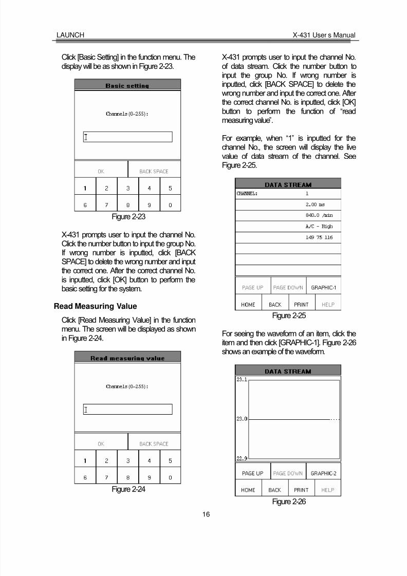
Click [Basic Setting] in the function menu. Thedisplay will be as shown in Figure 2-23.
Figure 2-23
X-431 prompts user to input the channel No.Click the number button to input the group No.If wrong number is inputted, click [BACKSPACE] to delete the wrong number and inputthe correct one. After the correct channel No.is inputted, click [OK] button to perform the
basic setting for the system.
Read Measuring Value
Click [Read Measuring Value] in the functionmenu. The screen will be displayed as shownin Figure 2-24.
Figure 2-24
X-431 prompts user to input the channel No.of data stream. Click the number button toinput the group No. If wrong number isinputted, click [BACK SPACE] to delete the
wrong number and input the correct one. After the correct channel No. is inputted, click [OK]button to perform the function of “readmeasuring value”.
For example, when “1” is inputted for thechannel No., the screen will display the livevalue of data stream of the channel. SeeFigure 2-25.
Figure 2-25
For seeing the waveform of an item, click theitem and then click [GRAPHIC-1]. Figure 2-26shows an example of the waveform.
Figure 2-26

8/14/2019 X 431user's Manual
http://slidepdf.com/reader/full/x-431users-manual 20/83
LAUNCH X-431 User’s Manual
17
Click [GRAPHIC-2] to display the waveformsof 2 data stream items. See Figure 2-27. It isconvenient for the user to make livecomparison between two correlative data
stream items.
Figure 2-27
Note:
♦ The screen will display the live value of
data stream again if the [DIGITAL] button is clicked in the interface.
♦ The three display modes -- [DIGITAL],[GRAPHIC-1] and [GRAPHIC-2] can be switched in turn.
Read Individual Measuring Value
Click [Read Individual Measuring Value] in thefunction menu. The screen will be displayed asshown in Figure 2-28.
Figure 2-28
X-431 prompts user to input the channel No.of data stream. Click the number button toinput the group No. If wrong number isinputted, click [BACK SPACE] to delete thewrong number and input the correct one. After the correct channel No. is inputted, click [OK]button to perform the function of “readindividual measuring value”.
For example, when “1” is inputted for thechannel No., the screen will display the livevalue of the channel. See Figure 2-29.
Figure 2-29
Adaptation
Click [Adaptation] in the function menu. Thescreen will be displayed as shown in Figure

8/14/2019 X 431user's Manual
http://slidepdf.com/reader/full/x-431users-manual 21/83
LAUNCH X-431 User’s Manual
18
2-30.
Figure 2-30
X-431 prompts user to input the channel No.of data stream. Click the number button toinput the group No. If wrong number isinputted, click [BACK SPACE] to delete thewrong number and input the correct one.
After the correct channel No. is inputted, click
[OK] button. X-431 prompts user to input theservice station code. See Figure 2-31.
Figure 2-31
After the code is inputted, click [OK] button.X-431 prompts user to input the matched data.See Figure 2-32.
Figure 2-32
After the correct channel No. is inputted, click[OK] button to perform the function of “adaptation”.When the adaptation is successful, the screenwill be displayed as shown in Figure 2-33.
Figure 2-33
Code Control Unit
Click [Code Control Unit] in the function menu.The screen will be displayed as shown inFigure 2-34.

8/14/2019 X 431user's Manual
http://slidepdf.com/reader/full/x-431users-manual 22/83
LAUNCH X-431 User’s Manual
19
Figure 2-34
X-431 prompts user to input the service stationcode. Click the number button to input theservice station code. If wrong number isinputted, click [BACK SPACE] to delete thewrong number and input the correct one.
After the service station code is inputted, click[OK] button. X-431 prompts user to input thecontrol unit code. See Figure 2-35.
Figure 2-35
Click the number button to input the controlunit code. If wrong number is inputted, click[BACK SPACE] to delete the wrong number and input the correct one.
After the correct control unit is inputted, click[OK] button to perform the function of “code
control unit”.
If the control unit can be coded, the screen willbe displayed as shown in Figure 2-36.
Figure 2-36
If the control unit can’t be coded, the screenwill be displayed as shown in Figure 2-37.
Figure 2-37
End Output
Click [End Output] in the function menu. X-431will return to the menu of tested systems.
Login Procedure
Note: Perform this function first before performing the functions l ike “ code control

8/14/2019 X 431user's Manual
http://slidepdf.com/reader/full/x-431users-manual 23/83
LAUNCH X-431 User’s Manual
20
unit ” , “ adaptation ” , etc.
Click [Login Procedure] in the function menu.The screen will be displayed as shown in
Figure 2-38.
Figure 2-38
X-431 prompts user to input the service stationcode. Click the number button to input theservice station code. If wrong number is
inputted, click [BACK SPACE] to delete thewrong number and input the correct one.
After the service station code is inputted, click[OK] button. X-431 prompts user to input thepassword. See Figure 2-39.
Figure 2-39
Click the number button to input the login
password. If wrong number is inputted, click[BACK SPACE] to delete the wrong number and input the correct one.
After the login password is inputted, click [OK]button. X-431 starts to log in. When the loginis successful, the screen will display theinformation as shown in Figure 2-40.
Figure 2-40
Click [OK] button to return to the functionmenu.

8/14/2019 X 431user's Manual
http://slidepdf.com/reader/full/x-431users-manual 24/83
LAUNCH X-431 User’s Manual
21
Update of DiagnosticSoftware
The Internet update function of X-431 providesuser with a convenient and quick way todownload the software from our website for update.
LAUNCH put the latest version of software towww. X431. com and display the massage onthe news page. User can use computer to visitthe Website in any part of the world. After registration, the latest version of software can
be downloaded. Then user can update hisX-431 by unzipping and installing the software.
Hardware Requirement
Necessary hardware:1. A computer that can access the Internet.2. A CF card reader/writer and a CF card that
need to be updated.
See Figure 3-01 for hardware connection.
Figure 3-01
1-CF card reader/writer 2-USB cable3-USB Port 4-Computer 5-CF card
l Insert the CF card into the CF cardreader/writer.
l Connect one end of the USB cable② to
the port of the CF card reader/writer ①,
and the other end to the USB port of thecomputer.
User Registration
Log on www. X431. com. See Figure 3-02
Figure 3-02
Select the favorite language in the pull-down
menu at the lower right of the interface toenter the homepage. See Figure 3-03.
Figure 3-03
Read Terms of Service
Click “Register ” in the interface shown inFigure 3-03 to open the window as shown inFigure 3-04.
Figure 3-04
Note:
When the member purchases one or more products after registration, he should log onto the member area, and then click

8/14/2019 X 431user's Manual
http://slidepdf.com/reader/full/x-431users-manual 25/83
LAUNCH X-431 User’s Manual
22
“ product control ” to register the newly purchased product. Refer to the section “ Member login ” .
The terms of service is shown in the screen.After reading and fully understand it, click “Iaccept” button to enter the interface shown inFigure 3-05.
Fill in Necessary Information
Fill in the serial No. of SMARTBOX,registration No. and dealer code in theinterface shown in Figure 3-05.
Figure 3-05
The serial No. of SMARTBOX is marked onthe back of SMARTBOX. The registration No.is in an envelope delivered with the product(the number must be kept confidential). Thedealer code is attached on the last page of the
user ’s manual.
After the information is filled, click “Next step” to enter the next interface shown in Figure3-06.
Note: When a product is sold, the dealer will log onto www. X431. com and enter the dealer code in the “ Dealer administration ” area so
that the user can do effective registration later. User should contact the dealer if registration can not be done effectively.
Figure 3-06
If the filled serial No. or registration No. is
invalid, the screen will display the message asshown in Figure 3-07. Click “OK” button toreturn to the previous interface to re-fill thecorrect numbers.
Figure 3-07
After information are filled in the interfaceshown in Figure 3-06, click “Next step” to enter
the next interface. See Figure 3-08.
Figure 3-08
Fill in the username and password. Then click“OK” button to enter the interface shown inFigure 3-09.
Figure 3-09
Up to now, the registration is completed. Click“Login“ to perform further operation or click“Close” to exit.
Note: Only the registered user can download and update the software .
Member Login
The user becomes the registered member after registration.Member can log in the website by filling

8/14/2019 X 431user's Manual
http://slidepdf.com/reader/full/x-431users-manual 26/83
LAUNCH X-431 User’s Manual
23
username and password in the interfaceshown in Figure 3-03.
Click if you forget
your password, and fill in necessaryinformation in the pop-up dialogue box shownin Figure 3-10.
Figure 3-10
Note: The E-mail account is very important as our webmaster will send the username and password to the account.
Member Area
When a registered member purchase one or
more new products, it is not necessary to click“Register ” on the homepage to register thenewly purchased product. Instead, he canenter username and password to log in, andthen click “member ” in the interface shown inFigure 3-11 to get into the member area. SeeFigure 3-12.
Figure 3-11
Figure 3-12
The member can perform the followingfunction:l Account administrationl Product controll
User ’s information maintenancel Order managementl Logout
Account Administration
It is for changing password.
Product Control
The following tasks can be performed for “Product Control” function:
l Register newly purchased product.l Hand over the machine to other customer.l Click serial No. to see the currently
available software version.
User’s Information Maintenance
It is for renewing the user ’s information.
Order Information
It is for checking the unpaid order.
Logout
When clicking “Logout”, the system will pop upa dialogue box as shown in Figure 3-13.
Figure 3-13
Click “OK” button to return to the hompage.
Software Download
Newly registered user can download, free of charge, the same software as that installed in
the purchased main unit, or the available later version of the software.
Click here to enter

8/14/2019 X 431user's Manual
http://slidepdf.com/reader/full/x-431users-manual 27/83
LAUNCH X-431 User’s Manual
24
After filling in the username and password,click “Login” to enter the interface as shown inFigure 3-14.
Figure 3-14
Select the SMARTBOX No. in Figure 3-14 andthen click “Next step” to enter the web page of software download.
The screen will show a list of software anddifferent versions for downloading. See Figure3-15. If no later version is released, the itemwill be marked “Not ready”.
Figure 3-15
Select the latest version and language, and
then click “Download” icon ( ) to open thefunction introduction page for the software.The information on the page includes newfunction, tested vehicle, hardware requirement,etc. See Figure 3-16.
Figure 3-16
A new page will appear when user clicks“Download” button. The pop up window willshow the description for updating thedownloaded software. See Figure 3-17.
Figure 3-17
Click “Download” button to save the softwareinto the user ’s computer.
It is necessary to download the “X-431 Updatetool” and put it in the same folder (e.g. “X-431update” folder) as other downloaded software
if it does not exist in your computer. It is goingto be used later during updating.
Precaution on operation of the CF cardreader/writer:
1)Install the driver
If it is the first time to use the CF cardreader/writer, you may have to install its driver.Use CD-ROM or floppy disk which are boughtseparately or delivered with the CF card
reader/writer to install the driver.
CF card reader/writer can use the defaultdriver in Windows Me/2000/XP and Mac OS9.x/Mac OS X. However, it is necessary toinstall the driver on Windows 98.
The installation procedure is as follows:1. Boot Windows 98.2. Insert the CD-ROM into CD-ROM drive.3. Connect CF card to the USB port of the
PC with the attached USB cable.4. Find and Double click on setup.exe file in
the catalogue of CD-ROM. The system willmake preparation for the installation. SeeFigure 3-18.
5. When the preparation is complete, thescreen will prompt to continue theoperation. See Figure 3-19. Click “Next” tostart installation.

8/14/2019 X 431user's Manual
http://slidepdf.com/reader/full/x-431users-manual 28/83
LAUNCH X-431 User’s Manual
25
Figure 3-18
Figure 3-19
6. When installation is finished, the screenwill display the information as shown in
Figure 3-20. Click “Finish” to exit.
Figure 3-20
When the CF card reader/writer is installed
successfully, a “Removable disk” iconwill be added in the catalogue of “Mycomputer ”.
Note:
♦ Do not unplug the CF card reader/writer from the USB port while its LED is blinking, otherwise data would be damaged!
♦ Data on CF card cannot be restored from the “ Recycle Bin ” once deleted.
2)Pull out the CF card
The CF card must not be pulled out when theCF card reader/writer is being used. Otherwise,the data in the CF card will be lost.
Procedure for pulling out the CF card:On the desktop of Windows, open the windowof “My computer ”. Click the right mouse buttonon “Removable disk” to pop up a menu. Select“Ejector (J)” in the menu. Then pull out the CFcard. The written data may be lost if the CFcard is pulled out discretionarily. When you
want to use the CF card again, put it in.
Software Update
Open the “X-431 update” folder, and double
click the icon . Then install the update toolaccording to the prompts on the screen.
When the installation is complete, the “X-431
update tool” icon will appear on thedesktop.
Make sure that the X-431 CF cardreader/writer and the CF card are wellconnected to the computer. Then double click
the “X-431 update tool” icon to run theprogram. The program will automatically checkthe downloaded update files, including thediagnostic program and the display program.See Figure 3-21.
Figure 3-21
Select the module for update in the interface

8/14/2019 X 431user's Manual
http://slidepdf.com/reader/full/x-431users-manual 29/83
LAUNCH X-431 User’s Manual
26
shown in Figure 3-21, and click “Update” iconto update. When the update is complete,prompts will appear to notify successfulupdate.
Description of icons at the lower left of the interface:
♦ Source folder : to show the route that the update program is from. The default one is where the last software from.
♦ Target folder : to show the route that the update program will be installed. It is CF card in this situation. It is necessary to click this button to designate the
removable disc when laptop computer is used.
The required space and available space arelisted at the lower left of the interface. If theavailable space is not enough to perform the
operation, click to show the installedprograms. See Figure 3-22.
Figure 3-22
Select the programs that can be deleted andclick “Delete” button to make some morespace available.

8/14/2019 X 431user's Manual
http://slidepdf.com/reader/full/x-431users-manual 30/83
LAUNCH X-431 User’s Manual
27
Flow Chart of X-431 Update for New User
For unregistered user For member
Click [Register]
Select language
Install and run X431 update tool
Download software and update tool
Log on www. x431. com
Select SMARTBOX Serial No.
Complete the registration
Read terms of service, click [I accept]
Enter username and PW
Select module and perform update
After update, press [ESC]
Connect CF card writer and CF card,install CF card writer driver
Click [Login]

8/14/2019 X 431user's Manual
http://slidepdf.com/reader/full/x-431users-manual 31/83
LAUNCH X-431 User’s Manual
28
Main Unit
IntroductionInterface
Turn on the power source, and then press[Power] key on the machine. The screen willdisplay the prompts about touch screencalibration. Press [Hot] key (refer to thesection “Calibrate Touch screen” for detailedsteps) if you want to make calibration,otherwise, you can wait until it displays thestart interface as shown in Figure 4-01.
Figure 4-01
Note: An interface for User Register will be displayed when the machine is started at
first time. Refer to the section “ User Register ” for detailed steps.
When you want to turn off the machine, pressand hold [Power] key for at least 2 seconds.
[Start] button: Its function is the same as that
in Windows. Click it to pop up the start menu.The items and their respective functions in themenu are shown in the following table.
[ ] Active Taskbar Icon: Click it by stylus todisplay and switch the executed programs.
[ ] Back Light Icon: Click it to turn on/off back light.
[ ] Soft Keyboard Icon: Click it to activatethe soft keyboard. Then you have two ways tochoose:1. Input by soft keyboard;
2.
Input by writing board.
Functions:
MemoTo record all kinds of important information and ideas, and makecorresponding classification.
AddressTo store the detailed information of relative, friends, colleaguesand business partners, which can be easily edited, retrieved andsearched.
To DoIt is convenient for user to record the business to do or beingdone, to delete or add task records, to arrange the priority of tasks, and to browse the classified tasks.
PIM(PersonalInformationManagement)
Schedule
To arrange the appointments, journeys and meetings in a whole
day; to check time schedule on business daily, weekly, monthlyand/or annually; and to describe the place, time and other details for each schedule record.

8/14/2019 X 431user's Manual
http://slidepdf.com/reader/full/x-431users-manual 32/83
LAUNCH X-431 User’s Manual
29
Calculator Both simple and scientific calculators are available.
World TimeThe time of many big cities in the world are offered. It is a helpfulassistant for your travel.
Mini Dictionary
An English-Chinese dictionary embodies a large number of
words, which cover all fields to overcome your inconvenience inlanguage.
Picture View To enjoy all kinds of pictures which can be zoomed in/out.
Tools
RunTo start executable applications which are based on theoperating system of the unit.
FIR It is a kind of chess.Game
Reversi To play for a while in your leisure time.
ApplicationTo link the application with the ‘Start’ menu, or delete it from the‘Start’ menu.
Power Management
To preset the use of power to save on electricity as possible.
Clock Set To set the system time.
Contrast To adjust the contrast of display.
Control Panel
Language Set To select language to be used.
Vehicle diagnosis Professional function of vehicle diagnosis.Vehiclemaintenance Sensor test and
simulationTo test the sensor on vehicle and simulate the output signal fromthe sensor.

8/14/2019 X 431user's Manual
http://slidepdf.com/reader/full/x-431users-manual 33/83
LAUNCH X-431 User’s Manual
30
Input
Note: To input data, please activate Soft Keyboard with stylus and use the stylus in the subsequent operations.
Using the Soft Keyboard
Activate and Hide
You can click Soft Keyboard icon on the bottomof the touch screen to activate the softkeyboard, and click again to hide it.
Input by Soft Keyboard
You have two ways to choose. One is to input
by Soft Keyboard just like normal keyboard, butwith stylus instead of finger. The other is toinput by writing board.
Click [En] button, it will switch from normalkeyboard to writing board [Hw]. And click [Hw]button, it will switch back.
The Function Key
There are four function keys on the upper-right
of the Soft Keyboard. SBC/DBC case,punctuations, Keyboard/Writing board, and theSoft Keyboard position can be determined byclicking one of the four keys for each of thefunctions from left to right. (Refer to Figure4-02)
The four function keys at the upper-middleposition are for moving the cursor leftward,rightward, upward or downward.
Figure 4-02
In keyboard mode, the key at the bottom left of the keyboard is [Shift] key. Click it to change thelowercase letter into the uppercase letter, and
the numeral key into special symbol (same asthe special characters corresponding to thenumeral keys in normal keyboard). The white
key at the bottom right of the Soft Keyboard isspace key.
Figure 4-03
In writing board mode (refer to Figure 4-03),there are eight function keys at the lower left of the soft keyboard. The four ones on the bottomimplement the function: to move the cursor
leftward, rightward, upward or downward. Theother four functions are (from left to right): todelete the first character before the currentcursor, clear the hand-writing section, spaceand return.
Input by Keyboard
1) Open an interface, such as User information.
2) Click Soft Keyboard Icon in the tool bar toactivate Soft Keyboard.
3) Click the characters on Soft Keyboard toenter data. (Refer to Figure 4-04)
Input by Writing Board
1) Open an interface, such as Memo.2) Click [New] button.3) Click the function key to switch to Writing
Board. (Refer to the section “Use for SoftKeyboard”).
4) Write on the white board to the right of theSoft Keyboard. Enter the information by
function key operation.

8/14/2019 X 431user's Manual
http://slidepdf.com/reader/full/x-431users-manual 34/83
LAUNCH X-431 User’s Manual
31
Figure 4-04
Control of App
Check Box
Figure 4-05
Click the check box to select the function. Whenthe function is selected, 'X ' will be marked inthe check box and the function description willbe displayed on the right of the check box. Youcan select several functions at the same time.
(Refer to Figure 4-05)
Figure 4-06
Scrolling Bar
Scrolling Bar is usually at the right side of thetouch screen. You can click or drag it to operate.If the content can’t be displayed completely inone page, moving the Scrolling Bar can turn to
next page. (Refer to Figure 4-06)
Common Button
[ ] Button at top right corner of the interface:After clicking it, current interface will be closed.When editing is being done, clicking of thebutton will be treated as quitting the editing.
[ ] Button at top right corner of the interface:
After clicking it, the help information will be
shown.
[Cancel] Button in the interface: After clicking it,current interface will be closed.
Help
Click [ ] button at the top right corner of theinterface to get helpful tips for current interface.

8/14/2019 X 431user's Manual
http://slidepdf.com/reader/full/x-431users-manual 35/83
LAUNCH X-431 User’s Manual
32
Tool and Game
Tools
Figure 4-07
1) Click [Start] button.2) Select ‘Tools’ in the pop-up menu.
3) Select the function needed in the pop-upsubmenu. (Refer to Figure 4-07)
Calculator
This calculator can perform not only commoncalculations as a simple calculator, such asaddition and subtraction, but also the functionoperations as a scientific calculator, such aslogarithm and factorial. (Refer to Figure 4-09).
1) In the pop-up menu of ‘Tools’, select
‘Calculator ’ to open the Calculator interface.
2) Click the square overlap icon on upper left of the screen to switch betweenscientific calculator and simple calculator.
3) Click ‘Unit Conversion’ button to switchbetween unit conversion calculator andsimple calculator.
Figure 4-08
Figure 4-09
Common Calculator (Refer to Figure 4-08):1) Click numeral keys on the screen to input.2) Or activate Soft Keyboard, and click
numeral key on Soft Keyboard to input.3) The operation is the same as that for
normal calculator.
Unit Conversion Calculator (Refer to Figure
4-10):1) Click ‘Unit type’ button at the top right
corner to select unit type.

8/14/2019 X 431user's Manual
http://slidepdf.com/reader/full/x-431users-manual 36/83
LAUNCH X-431 User’s Manual
33
2) Input the number to be converted in theblank next to the unit name, and then youwill see the conversion result.
3) If you want to return to simple calculator,
please click 'X' button at the top rightcorner to close the current interface.
Figure 4-10
World Time
Figure 4-11
1) In the pop-up menu of ‘Tools’, select‘world time’ to open the world time
interface.2) Click the button under the ‘Home Time’
icon to select region.3) Click the button under the ‘World Time’
icon to select region.4) Then you can see the time directly. (SeeFigure 4-11).
Dictionary
1) In the pop-up menu of ‘Tools’, select‘Dictionary’ to open the Dictionaryinterface. (See Figure 4-12)
2) Activate Soft Keyboard, and input words.3) Select the word from the list on the left.4) Click the word, and then you can find the
translation in the right list.
Figure 4-12
Picture View1) Click [Start] button.2) Select ‘Tools’ in the pop-up menu. (See
Figure 4-13)3) In the pop-up ‘Tools’ list, select ‘Picview’ to
open the Picture interface.
4) In the Picture interface, click icon in
the toolbar on the top. (See Figure 4-14)5) Select directory from the left list interface.6) Select file from the right list interface.7) Click [Parent Dir] button, and you can see
the directory of current directory’s parent.8) You can see the directory of the picture at
the right side of ‘Path’.

8/14/2019 X 431user's Manual
http://slidepdf.com/reader/full/x-431users-manual 37/83
LAUNCH X-431 User’s Manual
34
9) You can see the file name of the picture atthe right side of ‘File’.
10) Click [OK] button to open the picture.
Figure 4-13
Figure 4-14
Browse the pictures in current directory
1) In the Picture interface, click icon onthe top to browse the previous picture.
2) In the Picture interface, click icon on
the top to browse the next picture.Note: This operation is needed only when more
than one picture has been stored.
Zoom in and zoom out:
In the Picture interface, click or icon
on the top, then you can zoom in or zoom outthe current picture at will.
Game
Figure 4-15
1) Click [Start] button.2) Select ‘Game’ in the pop-up menu.3) Select the function in the pop-up
submenu. (See Figure 4-15)
FIR
1) In the pop-up submenu of ‘Game’, select‘FIR’ to open the Chess Board.
2)
Click black or white chessman to beginthe game. The one who select the blackchessman will start first. (See Figure4-16)
Rules for the game:You must try to make your five chessmen lineup and prevent your adversary from achievingthis goal in the process. The one whose 5chessmen are lined up first is winner. You canchoose the black or white chessman at the
bottom of the Chess Board before startingplaying.

8/14/2019 X 431user's Manual
http://slidepdf.com/reader/full/x-431users-manual 38/83
LAUNCH X-431 User’s Manual
35
Figure 4-16
Figure 4-17
Reversi
1) In the pop-up menu of ‘Game’, select‘Reversi’ to open the Chess Board. (SeeFigure 4-17)
2) Click [New Game] button to start.3) Click [Undo] button for pull back.4) Click [Close] button to close the Chess
Board.Rule:The one who chooses white chessman can play
first. All black chessmen between two whitechessmen will turn to white ones and all whitechessmen between two black chessmen willturn to black ones. So the player should be able
to reverse adversary‘s chessmen in each step.When the chessboard is full of chessmen, thenumber of the chessmen for each color shouldbe counted. The one who conserve morechessmen on the chessboard is winner.
PIM
1) Click [Start] button.2) Select ‘PIM’ in the pop-up menu.3) Select the function needed in the pop-up
list. See Figure 4-18.
Figure 4-18
MemoThe basic functions of Memo include: add newmemo, view memo, delete memo, browse bytypes, etc.1) In the pop-up ‘PIM’ list, select ‘Memo’ to
open the Memo interface. (See Figure4-19)
2) After you click the [▼] button on top right
corner, the type list will pop up. Then youcan select the type of the memo.
3)
You can also select the Edit Group in thetype list to open the Edit Group interface.4) The memo list of corresponding type will

8/14/2019 X 431user's Manual
http://slidepdf.com/reader/full/x-431users-manual 39/83
LAUNCH X-431 User’s Manual
36
be displayed in the list box on the midst of the Memo interface.
5) Click one memo in the memo list to openthe Memo Edit interface.
6)
Click [New] button to open the New Memointerface.
Figure 4-19
Add New Memo
1) In the Memo interface, click [New] buttonto open the New Memo interface.
2) Activate Soft Keyboard, and fill thesubject and contents.
3) Click the button on top right corner, thenselect the type in the pop-up list
4) Click [OK] button to save and close theNew Memo interface.
5) Then you can see the new memo in the
list box of the Memo interface.
View Memo
1) In the list box of the Memo interface, clickthe memo that you want to view.
2) Then you can view the contents of thememo in the opened Memo Edit interface.
3) Click [OK] button to close the Memo Editinterface.
Edit Memo
1) In the list box of the Memo interface, clickthe memo that you want to edit.
2) Then you can edit the contents of the
memo in the opened Memo Edit interface.See Figure 4-20.
3) After editing, click [OK] button to save theedited contents and close the Memo Edit
interface.
Figure 4-20
Delete Memo
1) In the list box of the Memo interface, clickthe memo that you want to delete.
2) Then you can delete the memo in theopened Memo Edit interface.
3) Click [Delete] button to delete the memoand close the Memo Edit interface.
Edit Type 1) Click the [▼] button on the top right of the
interface so that the type list pops up.
2) In the type list, select the Edit Group toopen the Edit Group interface.
3) In the Edit Group interface, activate SoftKeyboard.
4) In the text box at the bottom of theinterface, input the name of the type.
5) Click [Add] button to add a new type and itwill be displayed in the list box of the EditGroup interface. (See Figure 4-21)
6) Select one type in the list box, and thenclick [Delete] button to delete it.
7) Click [Close] button to close the EditGroup interface.

8/14/2019 X 431user's Manual
http://slidepdf.com/reader/full/x-431users-manual 40/83
LAUNCH X-431 User’s Manual
37
The interface : It represents the Memo Interface, the New Memo interface and the Memo Edit interface.
Figure 4-21
Browse By Types
1) Click the [▼] button on the top right of the
Memo interface so that the type list popsup.
2) Select the type in the list.3) Then you can see the memo belonging to
the type in the list box.
Note: Only the memo belonging to the type can be displayed here. If you want to browse all memos, please select ‘ All ’ in the steps 1and 2.
AddressThe basic functions of Address Book include:add new address, view address, delete address,to search address, etc.
1) In the pop-up ‘PIM’ list, select ‘Address’ toopen the Address Book interface.
2) It lists the name of persons whosecommunication information has beenstored.
3) Click [New] button to open the AddressNew interface. (See Figure 4-22)
4) Click [Find] button to pop up the FindPeople interface.
The operation guide for each function isdescribed below:
Figure 4-22
Add New Address
1) In the Address Book interface, click [New]button to open the Address New interface.(See Figure 4-23)
2) Activate Soft Keyboard, and fill thedetailed information on relatives andfriends.
3) Click [OK] button to save and close theAddress New interface.
4) Then the added name will be displayed inthe list box of the Address Book interface.

8/14/2019 X 431user's Manual
http://slidepdf.com/reader/full/x-431users-manual 41/83
LAUNCH X-431 User’s Manual
38
Figure 4-23
View Address
1) In the list box of the Address Bookinterface, click the name that you want toview.
2) Then the detailed information about theperson will be shown in the openedAddress Edit interface.
3) Click [OK] button to close the AddressEdit interface.
Edit Address 1) In the list box of the Address Book
interface, click the name that you want toedit.
2) Then the information about the personcan be edited in the opened Address Editinterface. See Figure 4-24.
3) After editing, click [OK] button to save theedited contents and close the AddressEdit interface.
Figure 4-24
Delete Address
1) In the list box of the Address Bookinterface, click the name that you want todelete.
2) Then the information about the person willbe shown in the opened Address Edit
interface.3) Click [Delete] button to delete the
person’s information and close theAddress Edit interface.
Search Address
1) In the Address Book interface, click [Find]button to pop up the Find People interface.See Figure 4-25.
2) Activate Soft Keyboard, and input the
name you want to search.3) Click [OK] button, and then you will see
that the name you search is highlighted inthe list box.

8/14/2019 X 431user's Manual
http://slidepdf.com/reader/full/x-431users-manual 42/83
LAUNCH X-431 User’s Manual
39
Figure 4-25
To Do
The basic functions of To Do include: add newTo Do, view To Do, delete To Do and set To Do,etc.
Figure 4-26
1) In the pop-up ‘PIM’ list, select ‘To Do’ itemto open the To Do interface.
2) The To Do list of corresponding items will
be displayed in the list box on the midst of the Memo interface.
3) Click [Options] button to open the To Do
Display interface. (See Figure 4-26)4) Click [New] button to open the To Do New
interface.
Add New To Do
Figure 4-27
1) In the To Do interface, click [New] button
to open the To Do New interface. SeeFigure 4-27.2) Activate Soft Keyboard, and fill in the
subject and contents.3) Click [Detail] button to open the To Do
Detail interface. See Figure 4-28.4) In the To Do Detail interface, click the
button to the right of ‘Group’ to pop up thetype list.
5) Click the button to the right of ‘Expired’,and select the data in the pop-up list.
6) Click the number to the right of ‘Priority’ toset the priority of the To Do.
7) If the To Do has been finished, pleaseclick the box to the right of ‘Finished’.When the function is selected, ‘X’ will bemarked in the box,.
8) Click [OK] button to save and close the ToDo Detail interface.
9) In the To Do Detail interface, click [OK]button to save and close the To Do Newinterface.

8/14/2019 X 431user's Manual
http://slidepdf.com/reader/full/x-431users-manual 43/83
LAUNCH X-431 User’s Manual
40
Figure 4-28
View To Do
1) In the list box of the To Do interface, clickthe to do that you want to view.
2) Then the contents of the To Do will beshown in the opened To Do Edit interface.
3) Click [OK] button to close the To Do Editinterface.
Edit To Do
1) In the list box of the To Do interface, clickthe memo that you want to edit.
2) Then the contents of the memo will beshown in the opened To Do Edit interface.
3) Click [Detail] button to open the To DoDetail interface, please refer to step 4~8in the section “Add New To Do”.
4) After editing, click [OK] button to save theedited contents and close the To Do Editinterface.
Delete To Do
1) In the list box of the To Do interface, clickthe to do that you want to delete.
2) Then the contents will be shown in theopened To Do Edit interface.
3) Click [Delete] button to delete the To Doand close the To Do Edit interface.
Edit Type
1) Click the [▼] button to the right of ‘Group’
in the interface so that the type listpops up.
2) In the type list, select ‘Edit Group’ to openthe Edit Group interface. See Figure 4-29.
3) In the Edit Group interface, activate SoftKeyboard.
4) In the text box at the bottom of theinterface, input the name of the type.
5) Click [New] button to add a new type andit will be displayed in the list box of theEdit Group interface.
6) Select one type in the list box, and thenclick [Delete] button to delete it.
7) Click [Close] button to close the EditGroup interface.
The interface : It represents the To Do Detail Interface (Refer to step 1-3 in the section “ Add New To Do ” and “ Edit To Do ” ),and the To Do Display interface (Refer to step 1 in the section “ The Set of Display ” ).
Figure 4-29

8/14/2019 X 431user's Manual
http://slidepdf.com/reader/full/x-431users-manual 44/83
LAUNCH X-431 User’s Manual
41
The Set of d isplay
Figure 4-30
1) In the To Do interface, click [Options]button to open the To Do Displayinterface.
2) In the To Do Display interface, click thebutton to the right of ‘Group’ to pop up
type list, and select the type in the pop-uplist.
3) Click the button to the right of ‘Expired’,and select the data in the pop-up list.
4) Click the number or ‘All’ to the right of ‘Priority’ to set the priority of the displayedTo Do.
5) Click the box to the right of each function.When ‘X’ is displayed in the box, thefunction is selected. (See Figure 4-30)
6) Click [OK] button to close the To DoDisplay interface.
7) Then you can see the corresponding To
Do in the list box of the To Do interface.
Schedule
The basic functions of Schedule include: addnew schedule, view schedule, delete schedule,etc.
Figure 4-31
1) In the pop-up list of ‘PIM’, select‘Schedule’ to open the Schedule interface.
2) Click the Date button on the upper left of the interface to open the Select Dateinterface.
3) In the list box in the middle of the
interface, all schedules on that daycorresponding to the Date button will bedisplayed. (See Figure 4-31)
4) Click [New] button, and then the cycle listpops up. You may select ‘Common’,‘Daily’, ‘Weekly’, ‘Monthly’ and ‘Annual’.
5 ) In the cycle list, select one item to openthe Schedule New interface.
Add New Schedule
Set the date of the schedule:
1) In the Schedule interface, click the Datebutton on the upper left to open the SelectDate interface.
2) In the Select Date interface, click [ ]icon to the left of the month or year toselect the previous month or year.
3) Click the [ ] icon to the right of themonth or year to select the next month or year. (See Figure 4-32)
4) Click to select the date in the current
month. When it is highlighted, it isselected.
5) Or click [Today] button to display the

8/14/2019 X 431user's Manual
http://slidepdf.com/reader/full/x-431users-manual 45/83
LAUNCH X-431 User’s Manual
42
current year, month and date directly.6) Click [OK] button to save the date setting
and close the Select Date interface.7) You may see the date you set on the
button on the top right of the Scheduleinterface.
Figure 4-32
Set the cycle of the schedule:1) In the Schedule interface, click [New]
button so that the Cycle list pops up. SeeFigure 4-33.
2) In the Cycle list, select ‘Common’ if it isdone on the selected date.
3) Select ‘Daily’ if it is done every day.4) Select ‘Weekly’ if it is done on a fixed day
every week.5) Select ‘Monthly’ if it is done on a fixed day
every month.6) Select ‘Annual’ if it is done on a fixed day
every year.7) After selecting, open the New Schedule
interface.
Figure 4-33
Set the content of the schedule:
Figure 4-34
1) In the Schedule New interface, activateSoft Keyboard, and fill the subject andcontents.
2) In the textbox on the top of the interface,fill the time of the schedule.
3) If the selected cycle is ‘Daily’, ‘Weekly’,
‘Monthly’ or ‘Annual’, you can input therepeat time in the textbox on the bottomof the interface. See Figure 4-34.

8/14/2019 X 431user's Manual
http://slidepdf.com/reader/full/x-431users-manual 46/83
LAUNCH X-431 User’s Manual
43
4) “Remind” function can be selected andthe reminding time can be set in theinterface. The “Remind” function will notbe available when the machine is turned
off.5) Click [OK] button to save and close theSchedule New interface
View Schedule
2) In the Schedule interface, select the datethat has been scheduled. (Refer to thesection “Add New Schedule à Set thedate of the schedule”)
3) In the list box of the Schedule interface,click Scrolling Bar to turn to next page,
and click the schedule you want to view.4) Then the contents of the schedule will be
shown in the opened Schedule Viewinterface.
5) Click [OK] button to close the ScheduleView interface.
Edit Schedule
1) In the Schedule interface, select the datethat has been scheduled. (Refer to thesection “Add New Schedule à Set the
date of the schedule”)2) In the list box of the Schedule interface,
click Scrolling Bar to turn to next page,and click the schedule you want to edit.
3) Then the contents of the schedule will beshown in the opened Schedule Viewinterface.
4) If the edited affair is ‘Daily’, ‘Weekly’,‘Monthly’ or ‘Annual’, you can edit therepeat time in the textbox on the bottomof the interface.
5) After editing, click [OK] button to save theedited contents and close the ScheduleView interface.
Delete Schedule 1) In the Schedule interface, select the date
that has been scheduled. (Refer to thesection “Add New Schedule à Set thedate of the schedule”)
2) In the list box of the Schedule interface,
click Scrolling Bar to turn to next page,and click the schedule you want to edit.3) Then the schedule will be shown in the
opened Schedule View interface. SeeFigure 4-35.
4) Click [Delete] button to delete it and closethe Schedule View interface.
Figure 4-35
System
Control Panel
The control panel includes all interrelatedsoftware and hardware configurations. It makesthe software more custom-built for you byconfiguring.
1) Click [Start] button.2) Select ‘Control Panel’ in the pop-up menu.
3 ) Open the Control Panel interface. (See
Figure 4-36)

8/14/2019 X 431user's Manual
http://slidepdf.com/reader/full/x-431users-manual 47/83
LAUNCH X-431 User’s Manual
44
Figure 4-36
Application
It displays the application information containedin the ‘Start’ menu, including the group name,the submenu, etc.
Figure 4-37
1) In the Control Panel interface, click ‘App’ icon to open the Application Manager interface.
2) Then you can see the correspondinginformation in the list box of the interface.(See Figure 4-37)
3) Insert a new group:Click [Insert] button and input the itemname. Then choose “Start” as its parent
and click [OK] button.
Figure 4-38
4) Insert a new submenu:Click [Insert] button and input the itemname and the file path. Then choose agroup as its parent and click [OK] button.The path can be inputted directly or foundout in a dialogue box after clicking[Browser] button. See Figure 4-38 andFigure 4-39. Click [OK] button after selecting an item in the list. Then theselected file will be automatically copied tothe edit box.
The submenu should be linked to apresent group instead of the “Start” item or another submenu.
5) Delete a group or a submenu:Select a group or a submenu and thenclick [Delete] button. When a group isdeleted, all of its submenus will be deleted.
6) Modify a group or a submenu:
Click [Modify] button and then select thegroup or submenu from the list. Now youcan modify the item name, file path and so

8/14/2019 X 431user's Manual
http://slidepdf.com/reader/full/x-431users-manual 48/83
LAUNCH X-431 User’s Manual
45
on followed by clicking [OK] button.
7) Save the information:After editing the application, click [OK]
button. The modified information will besaved in the corresponding file. If youwant to quit the modification, click [Cancel]button.
Note: Quit all other applications before saving the modification.
Figure 4-39
Power Management
In the Power Manager interface, you can seethe condition of memory, and set the standbytime. (See Figure 4-40)
1) In the Control Panel interface, click‘Power ’ icon to open the Power Manager interface.
2 ) Click the button to the right of ‘Standbytime’, and select the time or ‘None’ in thepop-up list.
3 ) Click [OK] button to save the setting andclose the Power Manager interface.
Figure 4-40
Clock
User can set the time and the time zone of thesystem.
Figure 4-41
Set Time:1) In the Control Panel interface, click ‘Clock’
icon to open the Date/Time interface asshown in Figure 4-41.
2) In the Date/Time interface, click [Set Time]
button to open the Set Time interface asshown in Figure 4-42.
3) Click the characters to the right of ‘Day’ to
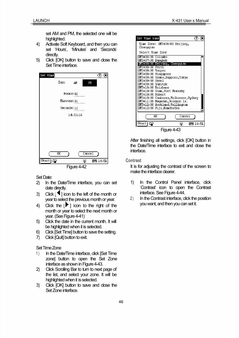
8/14/2019 X 431user's Manual
http://slidepdf.com/reader/full/x-431users-manual 49/83
LAUNCH X-431 User’s Manual
46
set AM and PM, the selected one will behighlighted.
4) Activate Soft Keyboard, and then you canset ‘Hours’, ‘Minutes’ and ‘Seconds’
directly.5) Click [OK] button to save and close theSet Time interface.
Figure 4-42
Set Date:2) In the Date/Time interface, you can set
date directly.
3) Click [ ] icon to the left of the month or year to select the previous month or year.
4) Click the [ ] icon to the right of themonth or year to select the next month or year. (See Figure 4-41)
5) Click the date in the current month. It will
be highlighted when it is selected.6) Click [Set Time] button to save the setting.7) Click [Quit] button to exit.
Set Time Zone
1 ) In the Date/Time interface, click [Set Timezone] button to open the Set Zoneinterface as shown in Figure 4-43.
2) Click Scrolling Bar to turn to next page of the list, and select your zone. It will be
highlighted when it is selected.3) Click [OK] button to save and close theSet Zone interface.
Figure 4-43
After finishing all settings, click [OK] button inthe Date/Time interface to exit and close theinterface.
Contrast
It is for adjusting the contrast of the screen tomake the interface clearer.
1) In the Control Panel interface, click‘Contrast’ icon to open the Contrastinterface. See Figure 4-44.
2 ) In the Contrast interface, click the positionyou want, and then you can set it.

8/14/2019 X 431user's Manual
http://slidepdf.com/reader/full/x-431users-manual 50/83
LAUNCH X-431 User’s Manual
47
Figure 4-44
Language
You can make selection among severallanguages for convenient operation of thesystem.
Figure 4-45
1) In the Control Panel interface, click‘Language’ icon to open the Languageinterface. See Figure 4-45.
2) Select the language you want to use.
3) Click [OK] button to confirm the selectionand close the language interface and theControl Panel interface.
Note: Before selecting language, be sure to quit all applications.
System Information
Calibrate Touch screen
It is for getting the desired accuracy of thetouch screen. Calibrating of touch screen canbe divided into two steps. The first step is todetect noise automatically. If you click the touchscreen at this step, the noise value would beaffected. After detecting the noise, the systemwill come to the calibration step. Then the crosscursor will be displayed.
1) After switching on the machine, follow thetips to press the hot key. The calibrationinterface will be opened.
2) Click the cross cursor on the screenaccurately, and wait until it changes. Thenone step of calibration is finished.
3) After calibration is finished for all corners,the system will automatically return to thestart-up main interface.
Note:
♦ Do not click the touch screen before the cross cursor appears.
♦ In the calibration step, if you fail to click the cross cursor accurately, the cross cursor will be displayed on the screen again and again until the calibration is finished completely.
User Register
The user ’s right can be well protected after registration.
1) Click [Start] button.2) Select ‘Information’ in the pop-up menu.3) Select ‘User ’ in the pop-up list to open the
User Information interface. (See Figure4-46)
4) In the User Information interface, activateSoft Keyboard, and input the user information. (See Figure 4-47)
5 ) Click [OK] button to save the informationand close the User Information interface.

8/14/2019 X 431user's Manual
http://slidepdf.com/reader/full/x-431users-manual 51/83
LAUNCH X-431 User’s Manual
48
Figure 4-46
Figure 4-47
About
In ‘Information’ list, click ‘About’ to display theinformation on system software and hardware,then click [OK] button to close it. (See Figure4-48)
Figure 4-48
Shut Down
Click “Shut Down” in the Start menu when youattempt to turn off the machine.

8/14/2019 X 431user's Manual
http://slidepdf.com/reader/full/x-431users-manual 52/83
LAUNCH X-431 User’s Manual
49
FAQ
X431 is a hi-tech product. With the
development of modern automotive industry,more and more new technology will be adoptedand there may be questions during operation.Read the user ’s manual to get the answer whenever you have any question, or contactour Customer Service Center for help.
Here we list some frequently asked questionsand answers relating to X431.
About Update via InternetQuestion: “Removable Disk” icon does notappear in the catalogue of “My computer ” after the CF card reader/writer is connected to theUSB port of computer. Why?
Answer:Possible cause: there may not be driver for CFcard reader/writer in the computer. The defaultdriver is with the operating systems like
Windows Me/2000/XP, Mac OS 9.x/Mac OS Xand Linux 2.4.X. However, there is no suchdefault driver with Windows 98.
Solution: Check if there is the driver for CFcard reader/writer in the computer. If thecomputer uses Windows 98 operating system, itis necessary to install the driver into computer by using the CD-ROM provided with CF cardreader/writer.
When the CF card reader/writer driver isinstalled successfully, a “Removable disk” iconwill appear in the catalogue of “My computer ”.Usually it is listed after original disk drive. For example, if there were drives A, B, C and Doriginally, the removable disk will be “E”. If therewere drives A, B, C, D and E originally, theremovable disk will be “F”. The rest may bededuced by analogy.
Question: Some downloaded diagnosticprogram is not listed in the update tool, what isthe reason?
Answer: There are two possible causes:1. The downloaded diagnostic program is notput in the same folder as other diagnosticprograms. Please move it to the same folder as
others.2. The diagnostic program is not fullydownloaded. Please download the programagain.
Question: When the updated software is usedin vehicle diagnosis, some diagnostic programcan not be downloaded successfully from theCF card. Why?
Answer: possible causes and solutions:
1. The Display Program may have not beenupdated. Please update the Display Program.2. The diagnostic program for the vehicle makeis damaged. Please re-download the diagnosticprogram and update.
Question: Why can’t the main unit recognizethe replaced CF card?
Answer: There are two possible causes:1. The original 32M CF card has not been fully
copied. Please delete the incomplete file andcopy again.2. The CF card reader/writer is not compatiblewith the CF card. Monofunctional CF cardreader/writer is better in such situation.
Question: How to make a new X431 CF cardwhen the data in old one is lost or damaged?
Answer: In case X431 CF card is damaged
and the program in the card can not be used,please use the following procedure to make anew CF card:
1. Log onto the website "www. X431. com".Enter your username and password to login.
Select the SMARTBOX No., and thendownload the following programs into your computer:
1) Necessary programs for making CF card:

8/14/2019 X 431user's Manual
http://slidepdf.com/reader/full/x-431users-manual 53/83
LAUNCH X-431 User’s Manual
50
l X431 UPDATE TOOLS---- for writingthe program from computer to CFcard when doing X431 update
l DISPLAY PROGRAM---- for
displaying the X431 diagnosticinformation and managing the X431diagnostic programs
l SYSTEM DATA---- system dataused by X431 system
2) Optional programs that can be selectedaccording to user's demand:Diagnostic program for various vehicles
2. Install the X431 UPDATE TOOLS into
computer.
3. Format the X431 CF card.
4. Run the X431 UPDATE TOOLS and writethe display program, system data anddiagnostic programs onto CF card.
About Hardware
Question: After X431 downloads the diagnostic
program from the CF card, it prompts “Pleasecontact your local dealer ”. What is the reason?
Answer: It is because the license No. in CFcard does not match the SMARTBOX. It can besolved in the following way:1. Download the software that is correspondingto the SMARTBOX so that the CF card canmatch the SMARTBOX.2. Use the UPDATE TOOL that is provided onhttp: // www. X431. com for update. Never useWINZIP or other decompressing tool for update.
Question: Why does the LCD screen respondso slowly?
Answer: It is because the ambient temperatureis close to the lower limit of operating
temperature range (0-50℃). In this situation, it
is necessary to warm up the machine for 20minutes before test.
Question: Power can not be turned on with thepower button on the main unit after the machine
is connected to vehicle diagnostic socketthrough cables and connectors. What can I do?
Answer: Check the power pin of vehicle
diagnostic socket with multimeter for power.The power pin in diagnostic socket varies fromone vehicle to another. Please refer to theUser ’s Manual of specific vehicle diagnosticprogram to find the power pin. If there is nopower supply from the diagnostic socket,please get power in other ways, such as frombattery or cigarette lighter.
Question: There is no character on the backlitscreen. What should I do?
Answer: Check if the power is well connected.Turn off the machine, unplug the power connector and re-plug it. Turn on the machineafter it has been connected to the power for 1second.
Question: Printer does not respond or itsprinted result is incomplete. What should I do?
Answer: Check if the printer is well connected
with the main unit. Unplug the printer connector and re-plug it again to check the printed result.
Question: Why can’t the diagnostic program bedownloaded to SMARTBOX?
Answer: Please make sure that theSMARTBOX is well connected with X431 mainunit.
Question: Why does X431 fail incommunication with ECU?
Answer: Please make sure that the diagnosticconnector and diagnostic program are matchingvehicle make.
Question: The screen keeps blank after flashing when the machine is turned on. Whatshould I do?
Answer: Take out the CF card and re-start themachine to see if there is normal display. If thedisplay is normal when the CF card is taken out,

8/14/2019 X 431user's Manual
http://slidepdf.com/reader/full/x-431users-manual 54/83
LAUNCH X-431 User’s Manual
51
the CF card should be replaced. If the screen isstill blank, please contact the local serviceengineer.
Question: Why does the system prompt that noCF card is found when the machine is turnedon?
Answer: The possible cause is that no CF cardis in the machine, or CF card is insertedimproperly or damaged. If it is damaged, it isnecessary to make a new one.
Question: What should I do if I can’t get intothe diagnostic interface during test?
Answer: The possible cause is that no CF cardis in the machine, or CF card is insertedimproperly or damaged. If it is damaged, it isnecessary to make a new one.
Question: Program is not run or screen isconfused after glints. What should I do?
Answer: Unplug the 9-pin connector on themain unit and re-plug it.
Question: What can I do if the system halts or fails during self-detection?
Answer: Please make sure that cables and CFcard are well connected.
Question: Why can’t the data be inputted after Soft Keyboard is activated?
Answer: The position where the cursor liescan’t be edited. Or you have not activated thecursor on the input position. Please use thestylus to click the part to edit. When the cursor twinkles, you can input the data.
Question: The screen is inactive after the crosscursor appears on the screen. Why?
Answer: The system is calibrating the touchscreen. The machine will work after the screen
is calibrated. Refer to the section “CalibrateTouch Screen” in User ’s Manual”.
Question: Why does the saved datadisappear?
Answer: There are two possible causes:
1. Your CF card is damaged.2. You’ve changed language and the data isrelated to language. You may find the data after switching back to the former language.
Question: How to know what applications(interfaces) are opened.
Answer: Click the active taskbar icon, then thepop-up list will display the applications(interfaces) opened.
Question: Why can’t I do operation in currentinterface?
Answer: There are two possible causes:1. Your current interface has exited illegally. Inthis situation, you may not see the name of theapplication (interface) in the pop-up list whenyou click the active taskbar icon.2. The system is busy, please wait patiently, or click the active taskbar icon to switch to another
application.
Question: The listed icons of vehicle makeoccupy more than one page of screen. I mayhave to turn several pages to find a specificicon of vehicle make. How can it be simplified?
Answer: X431 can test many vehicle makesand the vehicle makes are still increasing. Wehave considered the convenience when
designing the software. The system will countthe clicks and move the icon with more clicksforward.
About System Setting
Question: The screen is too white andcharacters can not be seen. What is the reasonand what should I do?
Answer: It may be caused by improper contrast.
Please refer to the section “Contrast” to adjustthe contrast.

8/14/2019 X 431user's Manual
http://slidepdf.com/reader/full/x-431users-manual 55/83
LAUNCH X-431 User’s Manual
52
Question: The screen is inactive after the crosscursor appears on the screen. Why?
Answer: The system is calibrating the touch
screen. The machine will work after the screenis calibrated. Refer to the section “CalibrateTouch Screen” in User ’s Manual”.
Question: The screen does not respond or responds wrongly when I click it with stylus.What should I do?
Answer: It is necessary to calibrate the screen.Please refer to the section “Calibrate TouchScreen” in User ’s Manual.
Question: The time displayed in the lower rightcorner of the screen is incorrect. How to adjustit?
Answer: It is because the time was setincorrectly. Please refer to the section “Clock” inthe User ’s Manual to set correct time.
About Operation
Question: System halts when reading datastream. What is the reason?
Answer: It may be caused by a slackenedconnector. Please turn off the machine, firmlyconnect the connector, and switch on themachine again.
Question: Why is the screen inactive when thecross cursor is clicked during screencalibration?
Answer: You may have touched the screenwhen the system is detecting noise before thecross cursor appears. Please turn off themachine and then turn on. Calibrate the screenafter the cross cursor appears.
Question: Why is the machine automaticallypowered off during standby?
Answer: It is because the machine has beenset for energy saving. Automatic shutdown willtake place if the machine is not operated for a
specified period of time. Refer to the section“Power management” in User ’s Manual to setthe “Power off time” to“None” or select a longer standby time.
Question: Why can’t the tested result beprinted out?
Answer: There may be no paper in the printer or the printer is not well connected. Pleasemount a roll of new paper. See the section“Printer Operation” in the User ’s Manual.
Question: Why is there no character in theprinted paper?
Answer: The paper is mounted reversely.Please take out the paper and mount it again.See the section “Printer Operation” in theUser ’s Manual.
Question: The displayed information can notbe seen clearly when the ambient light is notgood. What should I do?
Answer: There is a [ ] icon at the lower rightcorner of the screen. Click it to turn on the backlight so as to see the displayed informationclearly. Click the icon again for turning off thebacklight.
Question: Why can’t I input data after activating Soft Keyboard?
Answer: The position where the cursor liescan’t be edited. Or you have not activated the
cursor on the input position. Use the stylus toclick the part to edit. When the cursor twinkles,you can input the data.
Question: What should I do if I am not able toswitch from Active Taskbar to the runningapplication interface?
Answer: Please close interfaces related to theapplication, such as the Help or Detail.
Question: Why does the saved datadisappear?

8/14/2019 X 431user's Manual
http://slidepdf.com/reader/full/x-431users-manual 56/83

8/14/2019 X 431user's Manual
http://slidepdf.com/reader/full/x-431users-manual 57/83
LAUNCH X-431 User’s Manual
54
About ECU
In the last two decades, we have seen moreand more extensive application of IT andelectronic technologies in modern vehicles.Many vehicle control systems, typically EFI(Electronic Fuel Injection), ABS (Anti-blockBraking System), SRS (Air Bag), TC (TractionControl), AT (Automatic Transmission), etc., arecomputerized. Computerization makes thecontrol precisely, quickly, effectively and safely.Consequently, a significant progress in vehicledriveability, fuel economy, power performance,comfortability, emissions, safety and so on has
been made.
Composition and WorkingPrinciple of Computer-Control System
The Computer Control System consists of theon-board computer, and several related controldevices (sensors, switches, and actuators).Most on-board computers are located inside thevehicle behind the dashboard, under thepassenger ’s or driver ’s seat, or behind the rightkick panel. Some manufacturers may stillposition it in the engine compartment. Thesensors, switches, and actuators are devicessuch as oxygen sensors, coolant temperaturesensors, throttle position sensors, fuel injectors,etc., that are located throughout the engine,and are connected by electrical wiring to theon-board computer. As an example, thediagram of engine control system is shown in
Figure 6-01.
Figure 6-01
Sensor
It is a device that converts non-electric variableinto electric signal. More than 50 types of sensor are used in modern vehicles, most of which are found in powertrain, chassis controlsystems, body control system, safety system,etc.
According to the physical variables controlled,sensors are sorted into following types:temperature sensor, pressure sensor, air flowsensor, position/angular sensor, gasconcentration sensor, rotary speed sensor,acceleration sensor, vibration sensor, lightsensor, distance sensor, electrical currentsensor, angular speed sensor, shaft sensor,liquid level sensor, etc.
The commonly-used sensors in correspondingcontrol systems of vehicle are:
1) In engine management system: intake air pressure (or air flow), air/fuel ratio,crankshaft position, knock, RPM, intake air temperature, coolant temperature and O2 sensors.
2) In transmission system: vehicle speed,
throttle position, RPM, A/T output shaftspeed, toque, oil pressure/temperature,shift position sensors.

8/14/2019 X 431user's Manual
http://slidepdf.com/reader/full/x-431users-manual 58/83
LAUNCH X-431 User’s Manual
55
3) In braking system: vehicle speed, wheelspeed, deceleration, sliding rate, brakingpedal force, braking pedal position sensors,etc.
4) In steering control system: steering, vehicleacceleration, vehicle speed sensors, etc.
5) In suspension system: vehicle speed,vehicle height, steering angle, throttleposition, braking force sensors, etc.
6) In A/C system: external temperature,internal temperature, sunshine, coolanttemperature, refrigerant pressure and
humidity sensors, etc.
7) In instrument, alarm and diagnosis systems:remaining fuel, coolant temperature, oilpressure, oil status, intake air pressure,windshield washer fluid level, battery liquidlevel, door lock, braking fluid level sensors.
ECU
The electronic control unit is composed of input
circuit, A/D converter, SMC, output circuit, etc.See Figure 6-02.
Figure 6-02
1- Sensor 4- A/D converter 7- SMC
2- Analog signal 5- output circuit 8- Digital signal
3- Input circuit 6- Actuator 9- ROM/RAM
1) Input circuit: digital signal from sensor willenter the CPU directly. However, theanalogue signal will be treated in the A/D
converter before getting into CPU. Theinput circuit filters out the noise, convertssine wave into rectangular wave and then
into electrical parameter.
2) A/D converter: it converts the analogue
signal from the sensor into digital signal.
Then the digital signal can get into SMC.
3) SMC: it consists of I/O interface, CPU,RAM/ROM, etc. The received digital signalis computed here with the pre-programmedparameters from ROM. The computedresult is transmitted through I/O interface tothe output circuit, and then to thecorresponding actuators.
The data in ROM is written by manufacturer and will not be lost when power is off.However, the data in RAM will be lost whenpower is off.
4) Output circuit: it is to amplify the signal fromSMC. The weak current from SMC is notable to activate the actuator. So it has to beamplified.
Actuator
Actuator is to convert the electrical signal intoforce or displacement. The popular actuatorsare listed below:
1) Solenoid valve: This actuator is to convertelectrical signal into linear movement. Twotypes of solenoid valves are used in thevehicle. One is directly driven with linkage,e.g. the magnetic switch of starter motor.The other is for controlling pressure and
flow by transferring the movement torelevant valves. For example, in engineintake air control, electronically controlledautomatic transmission, suspension control,etc.
2) Motor: DC motor is the most popular actuator used in automobile. It can bedivided into two types according to its use.One is rotated by power, e.g. windshieldwiper, seat adjuster, etc. The other is used
in servo mechanism. In this situation,external force makes the rotor rotatearound the stator, e.g. the servo motor for

8/14/2019 X 431user's Manual
http://slidepdf.com/reader/full/x-431users-manual 59/83
LAUNCH X-431 User’s Manual
56
damper.
Besides the two types listed above, there areother types, such as relay, electronic switch,
etc.
Self-diagnosis of ElectronicControl System
All modern cars are controlled by an ElectronicControl Unit (ECU). The main purpose of theelectronic control system is to providemaximum engine performance with the leastamount of air pollution and the best fuelefficiency possible. However, the complexity of
the system may increase the difficulty for itstroubleshooting. The function of self-diagnosisis for solving such problem with electroniccontrol system.
Working Principle of Self-diagnosis
The composition of self-diagnosis system issimilar to electronic control system. The basiccomponent is electronic control unit. The mainpurpose of self-diagnosis system is to diagnose
the sensors, actuators, circuits and ECU invehicle.
The computer assigns a numeric code for eachspecific problem that it detects, and storesthese codes in its memory for later retrieval,and turns on the fault indicator on the dashpanel to warn the driver. The problem detectedmay be: inputted/outputted signal exceeds thespecified range, or some circuit isshort-circuited or open.
Now let’s take gasoline injection control systemas an example to describe the working principleof the self-diagnosis system. When problemoccurs, the process of diagnosis and treatmentwill be as follows:
1) For sensor If the output signal from the sensor is out of thespecified range of voltage when engine is
running, it will be deemed as fault. For example,the normal output voltage from coolanttemperature sensor should be in the range of
0.3-0.4V. If not, the situation will be deemed asfault and fault code will be stored in memory.Self-diagnosis system can detect damagedsensor, or short/open circuit, but it can not
appraise the performance of sensor. Occasionaloccurrence of abnormal signal will not bedeemed as fault immediately. For not beinginterrupted by the sensor fault, the engine willbe controlled by the pre-stored normal coolant
temperature (e.g. 80℃) from the self-diagnosis
system.
2) For actuator When the engine is running, ECU sendscommands to actuators according to the
practical situation. If the actuator can not worknormally, the monitoring circuit will transmit themessage to the ECU. ECU can make themessage displayed and take measures toensure the safe running of engine. For example,when the power tube in engine ignition systemis out of order, the ignition monitoring circuitsends feedback to the ECU. ECU emitswarning signal and sends commands toactuator for stopping injection so as to preventthe unburnt mixture from damaging the catalyticconverter of exhaust system.
3) For ECUThere is no monitoring circuit, but a monitoringclock in the ECU for resetting ECU regularly. If ECU is out of order, its program will not be runand the clock will not reset the ECU so thatoverflow may occur. This situation is deemed asfault for displaying.
For preventing unexpected stopping of vehiclecaused by problem with ECU, there is a backupcircuit in ECU. When the backup circuitreceives the signal of abnormality from themonitoring circuit, a spare control program willbe started for keeping the engine running aspre-programmed.
Readout of Fault Code in AutomotiveSelf-diagnosis System
The fault in vehicle electronic system is storedin KAM of ECU as fault code. The fault codecan be read out by the on board diagnostic

8/14/2019 X 431user's Manual
http://slidepdf.com/reader/full/x-431users-manual 60/83
LAUNCH X-431 User’s Manual
57
system or external scan tool.
The on board diagnostic system in differentvehicle may indicate the fault in different way. In
general, the following ways are popular:
1) Blinking of fault indicators on the instrumentpanel
2) Swing of multimeter index3) Blinking of red/green LED on ECU4) Shown by a special device
The more intuitionistic way for showing the faultis by external scan tool.
The diagnostic system of modern cars isequipped with diagnostic socket or DLC (datalink connector). Fault code in vehicle ECU canbe read out by connecting a scan tool to thediagnostic socket. In early time, each vehiclesystem had its own type of diagnostic socket.Since 1996, SAE has specified a uniformsystem called OBDII on board diagnosticsystem. Each vehicle that is made inaccordance with the system may have thesame diagnostic socket, same definition of pin
and same description of fault code. The controlunits of every system are connected to bus, soonly one diagnostic socket is needed for readout of fault code. OBD provides thepossibility of reading data stream anddisplaying working status of switches andactuators. Moreover, external scan tool cansend commands to activate the actuators.
X-431 is such an external scan tool for vehicle
diagnosis. It not only has the diagnostic functionlike reading fault code, reading data stream,actuation test, displaying sensor waveform,coding control unit, etc., but also has PDAfunction.
Basic Knowledge of ECU
Composition of Vehicle ECU
Vehicle ECU consists of ALU, CPU, power
source and memory.1. ALUIt converts the electronic signal from each
sensor into digital signal needed by CPU.
2. CPUThe digital signal is transferred to CPU for
computation and logical operation so thatcorrect air/fuel mixture can be obtained. CPUcan also compute ignition timing and idle speed,and control exhaust, fuel and diagnosticsystems.
3. Power sourceThe reference output signal (5V) of ECU andthe 12V voltage for control module are fromvehicle battery. Memory is also dependent onthe power supplied by the battery.
4. MemoryECU contains three types of memory: ROM,RAM and PROM (or EEPROM).
1) ROMROM stores the programming informationthat can only be read by ECU. The programin ROM is not editable. Power cut will notdamage the data in ROM.
2) RAMIt is for temporarily storing the inputted data,fault code and computed result. Power cutwill make all information in RAM erased.
3) PROMIts program is made by manufacturer to suitthe application of transmission, engine,exhaust control, driveability, rear axle ratio,etc. PROM is can be detached from ECU
and power cut will not damage the data init.
4) EEPROMIts function is similar to PROM. Thedifference between EEPROM and PROM isthat EEPROM can be re-programmed bymanufacturer with a special device.
Precautions Related to ECU
The circuit inside the ECU is very accurate andmay be easily damaged by overvoltage, staticelectricity and/or magnetic fields. Pay moreattention when diagnosing the devices that is

8/14/2019 X 431user's Manual
http://slidepdf.com/reader/full/x-431users-manual 61/83
LAUNCH X-431 User’s Manual
58
connected to ECU because most ECU’s areoperated under low voltage (about 5V).
Whenever you work in the vicinity of ECU or
engine control system, please obey thefollowing precautions:
1. Never damage the lead or connector.Prevent them from being grounded or contacting with an unexpected power source.
2. Never use the electrical test tool that ispowered by 6V battery or over. Strongcurrent may cause the element in ECUbroken or shorted. For checking the engine
control circuit, only the multimeter with largeinternal impedance (over 10MΩ) can beused.
3. Never try to disassemble or repair ECU if there are not necessary tools andinformation. Any mistake may damage thecomponent or increase the difficulty for service station.
4. The spark plug wire must be at least 25.4mm
from any sensor circuit or control circuit.Some unexpected fault in ECU circuit iscaused by magnetic fields that transmitwrong signal to ECU. High tension wire or transformer may interfere with ECU, but themost common cause for such problem is thatthe spark plug is too close to ECU harness.
5. Be careful when moving ECU or workingaround ECU. Remember that static electricity
may cause strong electrical shock anddamage ECU.

8/14/2019 X 431user's Manual
http://slidepdf.com/reader/full/x-431users-manual 62/83
LAUNCH X-431 User’s Manual
59
Appendix 1: about VIN
VIN is the abbreviation of Vehicle IdentificationNumbers.
A car ’s vehicle identification number (VIN) is theidentifying code for your SPECIFIC automobile.It is your car's fingerprint.
It sets your vehicles apart from the millions of vehicles out there. Recently the VIN is reflectedby 17 digit characters. It displays a car ’suniqueness and manufacturer and provides amethod to trace your car from the factory to the
junk yard.
Each character or digit has a particular purpose. They are as follows:
l First vehicle identification number digitidentifies the country from which the vehiclewas manufactured. For example, U.S.A.(1or 4), Canada (2), Mexico (3), Japan (J),Korea (K), England (S), Germany (W), Italy(Z).
l Second vehicle identification number digitspecifies the manufacturer. Audi (A), BMW(B), Buick (4), Cadillac (6), Chevrolet (1),Chrysler (C), Dodge (B), Ford (F), GMCanada (7), General Motors (G), Honda (H),Jaguar (A), Lincoln (L), Mercedes Benz (D),Mercury (M), Nissan (N), Oldsmobile (3),Pontiac (2 or 5), Plymouth (P), Saturn (8),Toyota (T), Volvo (V).
l Third vehicle identification number digitindicates the vehicle type or manufacturingdivision.
l Fourth through eighth vehicle identificationnumber digit reveals the vehicle featuressuch as body style, engine type, model,series, etc.
l The ninth vehicle identification number digit
is a VIN accuracy check digit, verifying theprevious VIN numbers. This is how thecheck digit works:
♦ STEP 1Assign to each number in the VIN itsactual mathematical value and assign to
each letter the value specified for it in thefollowing chart:
ASSIGNED VALUES:A=1 G=7 P=7 X=7B=2 H=8 R=9 Y=8C=3 J=1 S=2 Z=9D=4 K=2 T=3E=5 M=3 U=4F=6 N=4 V=5
♦ STEP 2Multiply the assigned value for eachcharacter in the VIN by the positionweight factor specified in the followingchart:
VIN POSITION AND WEIGHT FACTOR:1st = 8 10th = 92nd = 7 11th = 83rd = 6 12th = 74th = 5 13th = 65th = 4 14th = 56th = 3 15th = 47th = 2 16th = 38th = 10 17th = 29th = check digit
♦ STEP 3Add the products from steps 1 and 2 anddivide the total by 11.
♦ STEP 4The numerical remainder is the checkdigit which would appear in the 9thposition in the VIN. If the remainder is 10,then the letter "X" is used for the checkdigit.
l Tenth vehicle identification number digittells the model year. 1988 (J), 1989 (K),1990 (L), 1991 (M), 1992 (N), 1993 (P),1994 (R), 1995 (S), 1996 (T), 199 7(V),
1998 (W), 1999 (X), 2000 (Y)------2001(1),2002 (2), 2003 (3)

8/14/2019 X 431user's Manual
http://slidepdf.com/reader/full/x-431users-manual 63/83
LAUNCH X-431 User’s Manual
60
l Eleventh vehicle identification number digitreveals the assembly plant for the vehicle.
l The twelfth to seventeenth vehicle
identification number digits indicate thesequence of the vehicle for production as itrolled of the manufacturers’ assembly line.
Your VIN can be used to track recalls,registrations, warranty claims, thefts andinsurance coverage.
Common locations of the vehicle identificationnumber (VIN) vary but the following are placesto look:
l Firewall of the vehiclel Left hand inner wheel archl Steering columnl Radiator Support Bracketl Dash by windshieldl Drivers door or post on passenger sidel Guarantee & Maintenance Book *Vehicle
documentsl Machined Pad on front of enginel Component parts as listed above -eg-
engine, frame, etc.
Later model years - most common area's of VIN:l Left instrumentation/dash panel by windowl Drivers door or postl Firewall

8/14/2019 X 431user's Manual
http://slidepdf.com/reader/full/x-431users-manual 64/83
LAUNCH X-431 User’s Manual
61
Appendix II: Block and Parameter Definition ofVolkswagen Vehicle
Passat B5 Engine Data Stream Block Table
Display Definition
Block 00
1. 170...204
2. 17…44
3. 82...99
4. 142...206
5. 0...12
6. 123...133
7. 120...136
8. 77...179
9. 115...141
10. 117...138
1- coolant temperature
2- engine load
3- engine speed
4- ECM voltage supply
5- throttle angle
6- idle regulator
7- idle stable adaption value
8- O2 excessive regulator
9- mixture adaption value
10- mixture adaption value
Block 01
1. 820...900rpm
2. 1.00...2.50ms
3. 0…5∠0
4. 5.25...4.250VOT
1- engine speed
2- engine load (injection duration per revolution)
3- throttle angle
4- ignition angle
Block 02
1. 820…900 rpm
2. 1.00…2.50ms
3. 2.00…5.00ms
4. 2.0…4.0g/s
1- engine speed
2- engine load (injection duration per revolution)
3- engine injection duration per cycle
4- intake air volume
Block 03
1. 820…900rpm
2. 10…14.5V
3. 80…105℃
4. 90℃
1- engine speed (idle speed)
2- ECM voltage supply
3- coolant temperature
4- intake air temperature
Block 04
1. 0…5∠0
2. –1.70...1.70g/s
3. –1.70...1.70g/s4.
1- throttle angle(acceleration pedal depressed to theend75...95 0)∠
2- idle air mass adaption value (N gear)3- idle air mass adaption value (drive gear)
4-working conditionIdling idleTeillast part load

8/14/2019 X 431user's Manual
http://slidepdf.com/reader/full/x-431users-manual 65/83
LAUNCH X-431 User’s Manual
62
Vollast full loadSchub richAnreicherung O/D
Block 05
1. 820…900rpm
2. 860rpm
3. -10.0...10.0%
4. 2.0...4.0g/s
1- idle speed (idle speed)
2- idle speed (rated, M/T)
3- idle intake air regulation (idle regulator)
4- intake air volume
Block 06
1. 0...2550
2. -10.0...10.0%
3. -10.0...10.0%
4. -10…+45∠0
1- engine speed
2- idle intake air regulation ( idle regulator)
3-λregulator
4- ignition angleBlock 07
1. -10.0...10.0%
2. 0...1.100V
3. 0...99%
4. 0.30...1.10
1-λ regulator control
2-λ sensor voltage (higher than 0.45V denote rich,
less than 0.45V denote lean)
3- canister solenoid valve 1 duty ratio
4-λtrim with EVAP
Block 08
1. 2.00...5.00ms
2. -10.0...10.0%3. -8.0...8.0%
4.
1- injection time (per cycle)2- idle λ adaption value(add)3- part loadλ adaption (multiply)
4- EVAP modeTE active: canister solenoid activeTE not active: canister solenoid inactiveλ adaption: canister solenoid inactive, λ regulator active
Block 09
1. 820...900rpm
2. -10.0...10.0%
3. 0...1.100V
4. -10.0...10.0%
1- engine speed (idle rpm)
2-λregulator
3-λsensor voltage
4- idleλadaption value (add)Block 10
1. 0.00...0.30
2. -3...32
3. 0.30...1.20
4. 0...99%
1- canister solenoid valve 1 duty ratio
2-λmodification when the EVAP is active
3- canister charge rate
4- EVAP purge rate
Block 11
1. 820...920rpm
2. 2.00...5.00ms3. 0 km/h
4. 0.5...1.50 l/h
1- engine speed (idle rpm)
2- engine load3- vehicle speed
4- fuel consumption

8/14/2019 X 431user's Manual
http://slidepdf.com/reader/full/x-431users-manual 66/83
LAUNCH X-431 User’s Manual
63
Block 14
1. 820...920rpm
2. 1.00...2.50ms
3. 0...15.00KW4. 0...15.00KW
1- engine speed (idle rpm)
2- engine load
3- ignition delay of cylinder 1 due to the knock control4- ignition delay of cylinder 2 due to the knock control
Block 15
1. 820...920rpm
2. 1.00...2.50ms
3. 0...15.00KW
4. 0...15.00KW
1- engine speed
2- engine load
3- ignition delay of cylinder 3 due to the knock control
4- ignition delay of cylinder 4 due to the knock control
Block 16
1. 0.300...1.400V2. 0.300...1.400V
3. 0.300...1.400V
4. 0.300...1.400V
1- cylinder 1 knock sensor signal voltage2- cylinder 2 knock sensor signal voltage
3- cylinder 3 knock sensor signal voltage
4- cylinder 4 knock sensor signal voltage
Block 18
1. 820...920rpm
2. 1.00...2.50ms
3.
4. -30.0...25.0%
1- engine speed (idle rpm)
2- engine load (without altitude regulation)
3- engine load, throttle angle
4- altitude regulation factor
Block 19
1. 820...920rpm
2. 1.00...2.50ms
3.
4. 12∠0
1- engine speed (idle rpm)
2- engine load
3- working condition
×1×=without ignition delay, ×0×=with ignition delay
4- ignition angle
Block 20
1. 820...920rpm
2.
3.
4.
1- engine speed (idle rpm)
2- shift signal (P/N, 2, 3, 4, R, D)
3- AC mode
4- compressor mode on/off
Block 21
1. 820...920rpm
2. 1.00...2.50ms
3. 80…105℃
4.
1- engine speed (idle rpm)
2- engine load
3- coolant temperature
4-λmodification mode off/on
Block 23
1.
2. 72.0...95.0%
1-adption requirement the first digit:
1=adaption normally finished, 0=adaption requiredthe third to sixth digit:1=adaption not finished and abnormal, 0=adaption

8/14/2019 X 431user's Manual
http://slidepdf.com/reader/full/x-431users-manual 67/83
LAUNCH X-431 User’s Manual
64
3. 67.0...83.0%
4. 18.0...54.0%
finished, normalthe second and seventh digit: not use
2- minimal stop position of throttle regulator 3- urgency operation stop position of throttle regulator
4- maximal stop position of throttle regulator Block 24
1. 0...6800/mm
2. 0...10.00ms
3. -20...40∠0
4. 0...72.00KW
1- engine speed
2- engine load
3- ignition angle
4- cylinder 1...4 ignition retard angle
Block 25
1.
2. -30...300KW
3.
4. -3...210KW
1- engine working condition2- regulation error of Hall sensor 3- working condition (intake air manifold switch
over/camshaft regulation)(second digit by countdown 1=long intake air path, last digit denotecamshaft regulation (1=advance)
4- enable the camshaft regulation
Block 26
1. 0...6800/mm
2. 0...10.00ms
3.
4. -3...210KW
1- engine speed
2- engine load
3- working condition (intake air manifold switch
over/camshaft regulation)
4- enable the camshaft regulation
Block 951. 820...920rpm
2. 1.00...2.50ms
3. 12∠0
4. 80…105℃
1- engine speed (idle rpm)
2- engine load
3- ignition angle
4- coolant temperature
Block 98
1. 0.5...4.9V
2. 0.5...4.9V
3.
4.
1- throttle potentiometer voltage (G69)2- throttle regulator sensor voltage (G127)3- engine mode: idle/part load4- regulation mode:
adaptingadaption finishedadaption error
Block 99
1. 820...920rpm
2. 80…105℃
3. -10...10%
4.
1- engine speed
2- coolant temperature
3-λ regulation
4-λcontrol mode: off/on

8/14/2019 X 431user's Manual
http://slidepdf.com/reader/full/x-431users-manual 68/83
LAUNCH X-431 User’s Manual
65
Passat B5 AT System Data Stream Block Table
Display Definition
001
1.
2.
3.
4.
1- shift position (P/R/N/D/3/2/1)
2- throttle potentiometer voltage (idle 156...0.8V,throttle wide open 3.5...4.680V)
3- acceleration pedal (idle 0...1%, wide open throttle99...100%)
4- wide open throttle position (the first digit: 1=pedaldepressed, 2=pedal released. The second digit:1=TCS enabled, 0=TCS disabled. The third digit:not use. The fourth digit: 1=kickdown switchenabled, 0=kickdown switch disabled. The fifthdigit: for multifunction switch F125, R, N, D, 3, 2 is1;P, 1 is 0). The sixth digit: for multifunction switch
F125, P, R, 2, 1 is 1; N, D, 3 is 0. The seventhdigit: for multifunction switch F125, R, N, D, P is 1;3, 2, 1 is 0. The eighth digit: for multifunctionswitch F125, R, N, P is 1; N, D, 3, 2, 1 is 0.
002
1.
2.
3.
4.
1- solenoid valve 6-N93 rating current (neutral, wideopen throttle 0.0A, idle maximal 1.1A)
2- solenoid valve 6-N93 rating current (neutral, wideopen throttle 0.0A, idle maximal 1.1A)
3- battery voltage (10.8...16)4- VSS-G68 voltage (stop, .20...2.52V)
003
1.
2.
3.
4.
1- vehicle speed2- engine speed3- gear (neutral=0, reverse=R, gear 1 hydraulic=1H,
gear 1 mechanical =1M, gear 2 hydraulic =2H,gear 2 mechanical=2M, gear 3 hydraulic =3H, gear 3 mechanical=3M, gear 4 hydraulic =4H, gear 4mechanical =4M,)
4- acceleration pedal (idle 0...1%, wide open throttle99...100%)
004
1.2.
3.
4.
1- solenoid (solenoid 1-N88=1, solenoid 2-N89=2,solenoid 3-N90=3, solenoid 4-N91=4, solenoid5-N92=5, solenoid 7- N94=6.)Shift position:P=1010000;R=0010000;N=1010000;D, 3, 2, 1(1H, 1M)=0010000;D, 3, 2 (2H, 2M)=0110000;D, 3 (3H, 3M)=0000001;D (4H, 4M)=1100001.)
2- gear (same as block 003)
3- gear (P/R/N/D/3/2/1)4- vehicle speed

8/14/2019 X 431user's Manual
http://slidepdf.com/reader/full/x-431users-manual 69/83
LAUNCH X-431 User’s Manual
66
005
1.
2.
3.4.
1- ATF temperature2- shift output (the first and second digit: ignition
timing regulation ON=1, OFF=0; the third digit:shift lever lockup solenoid -N110 ON=1, OFF=0;
the fourth digit: kickdown solenoid ON=1, OFF=0;the fifth digit: CCS ON=1, OFF=0; the sixth digit:AC ON=1, OFF=0; the seventh digit: P/N signal, P,N=1, R=0, D, 3, 2, 1=1/0.)
3- gear (same as 003)4- engine speed
006 May be ignored
007
1.
2.
3.
4.
1- gear (same as block 003, “+” or “-” depend ondisplay area 2)
2- lockup clutch slip3- engine speed4- acceleration pedal (same as block 001)
008 May be ignored
Passat B5 ABS Data Stream Block Table
Block Definition
0011
234
1- FL rpm sensor wheel speed
2- FR rpm sensor wheel speed3- RL rpm sensor wheel speed4- RR rpm sensor wheel speed
0021234
1- brake light switch (1: brake pedal depressed=0,released=1)
2- pump generator voltage (1: with voltage,abnormal; 0: without voltage, normal)
3- solenoid relay (1: enabled; 0: disabled)4- not use
0031
234
1- engine speed (with ASR)2- engine torque (with ASR)
(0% engine at thrust stage, 20%...30% engineidle, 100% maximal engine torque)
3- ASR button (with ASR) (1: button pressed; 0:button not pressed)
4- not use
0041234
1- stop time2- EDS disconnected by too high braking
temperature (0: EDS does not disconnect during20 times ignition; 1: EDS disconnect during 20times ignition)
3- EDS/ASR disconnect (0: EDS/ASR normal; 1:EDS/ASR abnormal)
4- not use

8/14/2019 X 431user's Manual
http://slidepdf.com/reader/full/x-431users-manual 70/83
LAUNCH X-431 User’s Manual
67
Jetta Engine System Data Stream Block Table
Display Definition
00
1. 170...210
2. 26...50
3. 80...88
4. 176...2125. 4...126. 118...1387. 112...1148. 78...1789. 2242...255bzw
(or) 0…1310. 118...138
1- coolant temperature (about 80…110 )℃ 2- engine load (about 1.3...2.5ms)3- engine speed (about 800...880rpm)4- battery voltage (about12…14.5V)5- throttle angle (about 2…5 0)∠ 6- idle air flow regulation (idle regulator) (about
-2.5...+2.5kg/h)7- idle air flow adaption (about -4...+4kg/h)8-λ regulation (about-10...+10%)9-λ regulation adaption (add) (about -0.64...+0.64ms)10-λ regulation adaption (subtract) (about - 8...+8%)
01
1. 800...880 rpm
2. 1.3…2.5ms
3. 2…5∠0
4. 6…120VOT
1- idle rpm changes one time each 40 steps2- engine load3- throttle angle
fuel pedal fully depressed: 80…90∠0
when any throttle fault is detected: 35∠0
4- ignition angle
02
1. 800…880 rpm
2. 1.3…2.5ms
3. 2.0…5.0ms
4. 2.0…5.0g/s
1- idle speed changes one time each 40 steps2- theoretic fuel injection time per revolution of the crankshaft
3- the calibrated injection time of each working cycle4- intake air volume
03
1. 800…880rpm
2. 12…15V
3. 80…110℃
4. ... ℃
1- engine speed changes one time each 40 steps
2- battery voltage
3- coolant temperature
4- intake air temperature
04
1. 2…5∠0
2. -1.7…+1.7g/s
3. 0.00g/s
4. idle
1- throttle angle
2- idle air flow adaption3- always display ”0” for M/T4- working mode (idle, part load, full load, acceleration, O/D
cut off)
05
1. 800…880rpm
2. 840rpm
3. -10…+10%
4. 2.0…5.0 g/s
1- engine speed (practical) changes one time each 10 steps:
maximal 2550 rpm.
2- engine speed (set) changes one time each 10 steps
3- idle regulator 4- air flow

8/14/2019 X 431user's Manual
http://slidepdf.com/reader/full/x-431users-manual 71/83
LAUNCH X-431 User’s Manual
68
06
1. 800…880rpm
2. -10…+10%
3. -10…+10%
4. 6…120VOT
1- idle speed changes one time each 10 steps
2- idle regulator 3-λ--regulator 4- ignition angle
07
1. -10…+10%
2. 0…1V
3. 0…99%
4. 0.3…1.1
1-λ regulator
2-λ sensor voltage
3- canister N80 solenoid valve 1 duty ratio: 0= N80 closed,
99= N80 full open
4-λ calibration coefficient of EVAP
08
1. 2.0…5.0ms
2. -10…+10%
3. -8…+8%
4. TE active or TE inactive
1- injection time2-λ adaption at idle (add)3-λ adaption at full load (subtract)
4-”TE active” denote the canister solenoid valve 1 on and off according to the time (6 to 16 minutes).”TE inactive” denote the canister solenoid valve 1 always closed (1minute)
091. rpm
2. -10…+10%
3. 0…1.0V
4. -10…+10%
1- engine speed changes one time each 10 steps
2-λ—regulator 3-λ sensor voltage4- idle λ adaption (add)
10
1. 0…99%2. 0.3…1.2
3. -3…+32
4. 0.00…0.30
1- canister (AKF) solenoid duty ratio
2- EVAPλcalibration coefficient3- canister charging grade, -3 denote no fuel smoke in
canister; +32 denote the canister is full of fuel smoke4- canister filter purging grade (AKF) : 000 = AKF input; 0.30
=30% of intake air comes from AKF
111. 800…880rpm
2. 1.3…2.5ms
3. 0km/h
4. 0.5…1.5 l/h
1- engine speed changes one time each 40 steps2- engine load3- vehicle speed4- fuel consumption: the all displayed values are applicable
to the idle mode without extra load (AC, engine, power steering).
13
1. 0…150kw
2. 0…150kw
3. 0…150kw
4. 0…150kw
1- reduce ignition angle of cylinder 1 by knock regulation
2- reduce ignition angle of cylinder 2 by knock regulation
3- reduce ignition angle of cylinder 3 by knock regulation
4- reduce ignition angle of cylinder 4 by knock regulation
141. rpm
2. ms
3. 0…150
kw4. 0…150kw
1- engine speed changes one time each 40 steps
2- engine load (injection time per revolution)
3- ignition angle reduction of cylinder 1 by knock regulation4- ignition angle reduction of cylinder 2 by knock regulation

8/14/2019 X 431user's Manual
http://slidepdf.com/reader/full/x-431users-manual 72/83
LAUNCH X-431 User’s Manual
69
151. rpm
2. ms
3. 0…150kw
4. 0…150kw
1- engine speed changes one time each 40 steps
2- engine load (injection time each revolution)3- ignition angle reduction of cylinder 3 by knock regulation4- ignition angle reduction of cylinder 4 by knock regulation
161. 0.4…2.0V
2. 0.4…2.0V
3. 0.4…2.0V
4. 0.4…2.0V
1- knock sensor signal of Cyl 1
2- knock sensor signal of Cyl 2
3- knock sensor signal of Cyl 34- knock sensor signal of Cyl 4
181. 800…880rpm
2. 1.3…2.5ms
3.…ms4. -50…+25%
1- engine speed changes one time each 40 steps
2- air flow meter engine load
3- throttle angle engine load4- altitude calibration coefficient
201. 800…880rpm2. 00000100EIN
00000000AUS
3. A/C-high
A/C-low
4. Kompr.EINKompr.Aus
1- engine speed changes each 40 steps2- low octane number switch (if the fuel is poor, screen
display as below. 00000100EIN (open))3- AC
High=large AC power Low=small AC power
4- AC compressor on/off always display “Kompr.Aus” for vehicles without AC
211. rpm
2. ms
3. ℃
4. λ regulation off λ regulation on
1- engine speed changes each 40 steps2- engine load3- coolant temperature4-λregulation off/on
231. 01000000
2. 73…97%
3. 54…85%
4. 6…43%
1- adaption requirement
1= not use
2= throttle regulator potentiometer adaption minimalestimate value
“0”=adapted, adaption normal,“1”=adaption not performed, adaption abnormal3= throttle regulator potentiometer adaption maximal
compute value”0”=adaption performed, normal; “1”=adaption notperformed, abnormal
4= throttle potentiometer G69 adaption minimal computevalue “0”=adaption performed, normal; “1”=adaptionnot performed, abnormal
5= throttle potentiometer G69 adaption maximal compute
value”0”=adaption performed, normal;
“1”=adaption notperformed, abnormal
6=not use

8/14/2019 X 431user's Manual
http://slidepdf.com/reader/full/x-431users-manual 73/83
LAUNCH X-431 User’s Manual
70
7= throttle potentiometer G69 compare with the throttleregulator potentiometer, “0”=must compare, “1”=adaption not performed, abnormal;
8=not use
2- throttle regulator V60 minimal compute value3- throttle regulator V60 emergency compute value4- throttle regulator V60 maximal compute value
981. 0…5V
2. 0…5V
3. idlepart load
4. ADP activeADP normal
ADP abnormal
1- throttle potentiometer voltage
2- idle regulator potentiometer voltage3- mode
4- adaption mode
ADP=throttle control unit adaption
991. rpm
2. ℃
3. -10…+10%4. λ regulation -off λ regulation -on
1- engine speed2- coolant temperature3-λregulator 4-λregulation off/on
System basic setting function: λ regulation off.Read data stream function: λ regulation on
Golf Engine System Data Stream Block Table
Display Definition
Block 00
1, 2, 3, 4, 5, 6, 7, 8, 9, 10
Used by manufacturer
Block 01
1. about 800 rpm
2. 81...111℃
3. 0…1.0V
4. XXXX XXXX
1- engine speed
2- coolant temperature
3- O2 sensor voltage
4- engine mode
Block 02
1. about 800 rpm
2.
3. 81...111℃
4. entiroment temperature
1- engine speed
2- injection pulse width
3- battery voltage
4- intake air temperature
Block 03
1. about 800 rpm
2.
3.
4.
1- engine speed
2- engine load
3- throttle angle
4- ignition timing
Block 04

8/14/2019 X 431user's Manual
http://slidepdf.com/reader/full/x-431users-manual 74/83
LAUNCH X-431 User’s Manual
71
1. abou 800 rpm
2.
3. km/h
4. XXXX XXXX
1- engine speed
2- engine load signal
3- speed signal
4- engine modeBlock 05
1. about 800 rpm
2.
3.
4.
1- engine speed
2- engine load
3- mixture calibrate
4- mixture adaption value
Audi 200 Engine System Data Stream Block Table
Display DefinitionBlock 001, 2, 3, 4, 5, 6, 7, 8, 9, 10
Used by manufacturer
Block 011. 80...820rpm2. 29...59%3. not use4. 18-75steps
1- engine speed2- intake manifold pressure3- computed ignition angle4- N71 steps
Block 021. 0...85%2. not use
3. 81...111℃ 4. environment temperature
1- throttle opening2- intake air manifold pressure
3- coolant temperature4-intake air temperature
Block 031. 0.75...1.252. not use3. 0.75...1.254. not use
1-λ-control current adaption value (cylinder 1-3)0=λ control adaption active (AKF off)1= engine temperature too low4= idle rpm too low5= idle rpm too high6=λ sensor inactive7=λ control system inactive10=the rating adaption value not obtained
11=ignition angle retarded12=ignition angle advanced16=λ control system inactive(AKF active)
2-λ-control current adaption value (cylinder 4-6)3-λ-control (cylinder 1-3)4-λ-control (cylinder 4-6)
Block 041. not use2. not use3. 0.75...1.25
4. 0.75...1.25
1-λ-control adaption mode2- canister filter control current adaption value3-λ-control (cylinder 1-3)4-λ-control (cylinder 4-6)
Block 051.680...820 rpm 1- engine speed

8/14/2019 X 431user's Manual
http://slidepdf.com/reader/full/x-431users-manual 75/83
LAUNCH X-431 User’s Manual
72
2. value=600 3. not use
4. 81...111℃
2-knock control3-computed ignition angle4- coolant temperature
Block 06
1. 10...602. 18...753. not use4. not use
1- N71 position2- idle stable-control current adaption value3- influence on idle stable control by other signal4- idle stable control
Block 071. 10…60
2. 81...111℃
3. 0.75...1.254. not use
1- N71 position2- coolant temperature3-λ-control current adaption value (cylinder 1-3)4-λ-control current adaption value (cylinder 4-6)
Block 081. 10…60
2. 81...111℃
3. 0.75...1.254. not use
1- N71 steps2- coolant temperature3-λ-control current adaption value (cylinder 1-3)4-λ-control current adaption value (cylinder 4-6)
Block 09
1. 81...111℃
2. 1 or 03. not use4. 680...820rpm
1- coolant temperature2- idle switch-mode (0=on, 1=off)3- computed ignition angle4- engine speed
Block 10
1. 81...111℃
2. 1 or 03. 0.75...1.254. not use
1- coolant temperature2- idle switch -mode (0=on, 1=off)
3-λ-control current adaption value (cylinder 1-3)4-canister filter-current adaption value
Block 991.2.3.4.
1- engine current practical rpm2- engine current practical load3- coolant temperature4-λ regulation off/on
System basic setting function:Λ regulation off Read data stream function: λ regulation on

8/14/2019 X 431user's Manual
http://slidepdf.com/reader/full/x-431users-manual 76/83
LAUNCH X-431 User’s Manual
73
Appendix III: Channel Function Table ofVolkswagen Vehicle
Audi 200
Channel Function
00 idle stable valve
01 idle speed
Audi A6
Channel Function
02 Reset the service cycle after repair 03 Fuel consumption display adaption
04 Language selection
09 Mileage display
18 Stop heating system adaption
30 Fuel meter sensor characteristic curve adaption
35 rpm restriction adaption
40 Mile adaption after repair
41 Drive time adaption after repair
42 Minimal mile (km) adaption
43 Maximal mile (km) adaption44 Maximal interval adaption
45 Oil mass adaption
46 Total fuel consumption adaption
21 Immobilizer
Passat B5
Channel Function
03 Fuel consumption indication calibration
04 Language selection (only applicable to top-grade
combination instrument panel
09 Mileage display match
10 Replace oil service (OEL)-mileage
11 Mileage inspection (INSP)-counter maintenance-interval data
12 Time (unit 10-day interval) inspection(INSP)-maintenance data of the mileage counter
30 Gasoline storage indication match

8/14/2019 X 431user's Manual
http://slidepdf.com/reader/full/x-431users-manual 77/83
LAUNCH X-431 User’s Manual
74
Appendix IV: Control Unit Code of PopularVolkswagen Vehicles
Audi A6
1. Engine system:04002
2. Transmission system1) Vehicle without electronic throttle control
Code Engine Tiptronic mode DSP Market
00000
DSP effective Front wheel drive carsor 4 wheel drive carsin USA or areas other than Germany
00010
Applicable to everycombinations of transmission and
engine with noelectronic throttlecontrol
Old mode or non-Tiptronic
mode DSP ineffective (itshould be kept ONif possible)
Front wheel drive carsor 4 wheel drive carsin USA or areas other than Germany
Note:
♦ “ New ” in Tiptronic mode: when the speed selector is in Tiptronic channel, the transmission will automatically accelerate or decelerate before reaching the speed limit so that engine can run between the idle speed and the decelerated speed. The speed can also be slowed down when the accelerator pedal is fully depressed to kickdown;
♦ “ Old ” in Tiptronic mode: when the speed selector is in Tiptronic channel,acceleration/deceleration can only be realized by pushing the speed lever
forward(+)/backward(-). When the car is stopped after braking, the transmission will be automatically shifted to the first gear of staring.
2) Vehicle with electronic throttle control
Code Engine Tiptronic mode DSP Market
00000
00001 New DSP effective 4WD cars in areas other thanGermany
00011 New DSP ineffective 4WD cars in areas other thanGermany
00021 Old DSP effective 4WD cars in areas other thanGermany
00031 Old DSP ineffective 4WD cars in areas other thanGermany
00002 New DSP effective 4WD cars in USA
00012 New DSP ineffective 4WD cars in USA
00022 Old DSP effective 4WD cars in USA
00032 Old DSP ineffective 4WD cars in USA
00003 New DSP effective 4WD cars in USA
00013 New DSP ineffective 4WD cars in USA
00023 Old DSP effective 4WD cars in USA00033 Old DSP ineffective Other areas in the world
00004
Match of everytransmission andeffective enginewith electronic
throttle control
New DSP effective Front wheel drive cars in USA

8/14/2019 X 431user's Manual
http://slidepdf.com/reader/full/x-431users-manual 78/83
LAUNCH X-431 User’s Manual
75
Code Engine Tiptronic mode DSP Market
00014 New DSP ineffective Front wheel drive cars in USA
00024 Old DSP effective Front wheel drive cars in USA
00034 Old DSP ineffective Front wheel drive cars in USA
Note:
♦ “ New ” in Tiptronic mode: when the speed selector is in Tiptronic channel, the transmission will automatically accelerate or decelerate before reaching the speed limit so that engine can run between the idle speed and the decelerated speed. The speed can also be slowed down When the accelerator pedal is fully depressed to kickdown;
♦ “ Old ” in Tiptronic mode: when the speed selector is in Tiptronic channel,acceleration/deceleration can be realized only by pushing the speed lever forward(+)/backward(-). When the car is stopped after braking, the transmission will be automatically shifted to the first gear of staring.
3. ABS/ASR system
Engine Transmission Data transfer route ECU spare part No. and index Code
Manualtransmission012
CAN bus 8E0 614 111AHAJ
000322.4L,6 Cylinder,5 Valve
Manualtransmission01V
CAN bus 8E0 614 111AHAJ
00031
Manualtransmission
012
CAN bus 8E0 614 111AHAJ
000322.8L,6 Cylinder,5 Valve
Manualtransmission01V
CAN bus 8E0 614 111AHAJ
00031
1.8L4 Cylinder 5 Valve
Manualtransmission012
Single wire 8E0 614 111 B:FCan’tbecoded
4. Air bag system
Air bag system Code
Air bag 8: there are two front seat air bags, two front seat belt tensioners and two rear seatbelt tensioners in the car.
00004
Air bag: there are two front seat air bags, two front side air bags, front seat belt tensioner
and two rear seat belt tensioners in the car.00104
Air bag 8: there are two front seat air bags, two front side air bags, two rear side airbags,
front seat belt tensioner and two rear seat belt tensioners in the car.00204
5. Central door lock system
Without anti-theft alarm With anti-theft alarm
Safety device of central door lock (SZV) 4676 4686

8/14/2019 X 431user's Manual
http://slidepdf.com/reader/full/x-431users-manual 79/83
LAUNCH X-431 User’s Manual
76
Locking of trunk lid (when car is moving)4688 (without SZV)
4692 (with SZV)
4698 (without SZV)
4702 (with SZV)
Automatic locking of car door when car is
travelling at the speed higher than 40km/h
4704 (without SZV)
4708 (with SZV)
4714 (without SZV)
4718 (with SZV)
6. Internal ultrasonic monitoring system
Code 00001
00 Padding bit, insignificance
0 Audi A6
0 Original state: static
1 Four-door sedan
2 Touring car
7. Combined instrument system
ABCDE The code is a 5-digit number
AB Select equipment
00 No selectable equipment
01 Brake wear indicator
02 Seat belt warning system
04 Cleaning agent alarm system
16 GPS
C Country
0 Germany (D)
1 Europe (EU)
2 USA (US)
3 Canada (CDN)
4 Great Britain (GB)
5 Japan (JP)
6 Saudi Arabia (SA)
7 Australia (AUC)
D Number of cylinder
4 4 cylinders
6 6 cylinders
8 8 cylinders
E Engine type
0 TDL engine
2 4-cylinder and 6-cylinder engine
3 8-cylinder engine

8/14/2019 X 431user's Manual
http://slidepdf.com/reader/full/x-431users-manual 80/83
LAUNCH X-431 User’s Manual
77
8. Immobilizer : 07602
9. Radio set and telephone
5 4 3 2 1 Position of decimal code displayed on screen
7 Type of radio set
Antenna CD Secondary screen
1 X - -
3 X X -
5 X - X
7 X X X
“X”=with this part“—”=without this part
0 Audio system adjustment
Type of adjustment
0 Standard(Bose audio)
1 Bose audio system
2 Number of passive speaker
Number and position
0 Without passive speaker (Bose audio system)
1 1 left passive speaker (Bose with telephone)
2 2 front passive speaker and 2 rear active speaker
5 2 front passive speaker and no rear active speaker
0 Audio match0=Standard
0 Country0= Standard
10. Auxiliary heating system1) Control unit-J162 (software version No. is D47 or D48)
Code Signification
00001 Power cut owing to undervoltage for adaptation when basic setting is reached.
00002 Power cut owing to undervoltage when the inputted voltage for adaptation is reached.
Note:
♦ Enter code 00001 only. Code 00002 is entered according to customer ’ s request;
♦ For auxiliary heating device of which the spare part No. is 4B0 265 105, index No. is not higher than C and software version No. is D47 or D48, the spare part No. and software version No. can be read out by our scan tool in the function like [Read ECU memory];
♦ Power cut will be caused by undervoltage whenever the code is 00001 and the voltage of auxiliary heating device is lower than the battery vol tage for adaptation of basic setting;
♦ Power cut will be caused by undervoltage whenever the code is 00002 and the voltage of auxiliary heating device is lower than the battery voltage inputted for adaptation.
♦ If the fault message like “ Power cut owing to undervoltage (constant value)” is displayed for
auxiliary heating device (code is 00001), please perform the following steps: 1) Change the code of auxiliary heating device to 00002 and confirm the control unit code; 2) Read out the inputted value (constant value) of uncervoltage power cut by means of the

8/14/2019 X 431user's Manual
http://slidepdf.com/reader/full/x-431users-manual 81/83
LAUNCH X-431 User’s Manual
78
function [Adaptation] and then perform adaptation; 3) Alter the constant value by means of the function [Adaptation] (Specified value is below
10.5V); 4) Change the code of auxiliary heating device to 00001. Confirm the control unit code.
2) Control unit-J162 (software version No. is D49 or over)
Code Signification
00011With recirculation pump-V55Power cut owing to undervoltage for adaptation when the basic setting is reached.
00012With recirculation pump-V55Power cut owing to uncervoltage when the inputted voltage for adaptation is reached.
Note:
♦ Enter code 00011. Code 00012 is entered only if requested by customer;
♦ For auxiliary heating device of which the spare part No. is 4B0 265 105, index No. is higher than D and software version No. is D49 or over, the spare part No. and software version No.
can be read out by our scan tool in the function l ike [Read ECU memory]; ♦ Power cut will be caused by undervoltage whenever the code is 00011 and the voltage of
auxiliary heating device is lower than the battery voltage for adaptation of basic setting;
♦ Power cut will be caused by undervoltage whenever the code is 00012 and the voltage of auxiliary heating device is lower than the battery voltage inputted for adaptation;
♦ If the fault message like “ Power cut owing to undervoltage (constant value)” is displayed for auxiliary heating device (code is 00011), please perform the following steps:
1) Change the code of auxiliary heating device to 00012 and confirm the control unit code; 2 ) Read out the inputted value (constant value) of uncervoltage power cut by means of the
function [Adaptation] and then perform adaptation;
3 ) Alter the constant value by means of the function [Adaptation] (Specified value is below 10.5V);
4 ) Change the code of auxiliary heating device into 00011. Confirm the control unit code.
Passat B5
1. Engine system
Country/Emission rule Drive/Addit ional funct ion Transmission Vehicle model
00= 0=front wheel drive withoutASR / front wheel drive
without ESP
0=5-gear manualtransmission
0=
01= 1= 1= 1=grade B, e.g.Passat
02=EC member countriesI
2=Four wheel drivewithout ESP
2= 2=
03= 3= 3= 3=
04= EC member countriesII / Engine II withoutsecondary air system II(MVEG-II)
4= 4= 4=
05= 5= 5=A/T01VTiptronic
5=
06= 6= 6= 6=07= 7= 7= 7=

8/14/2019 X 431user's Manual
http://slidepdf.com/reader/full/x-431users-manual 82/83
LAUNCH X-431 User’s Manual
79
2. Air bag system
Equipment Index Code
There is air bag at driver side A 00065
There are air bags for driver/front passenger B 00066There are air bags for driver/front passenger (USA) C 00067
There are air bags for driver/front passenger/side air bag A 00065
There are air bags for driver/front passenger/side air bag (USA) B 00066
3. A/C
Code Vehicle
02000 Other than Japan
02100 Japan
05000 Other than Japan, 98.11
05100 Japan, 98.11
4. Comfort system
Equipment Code
One door open 00256Centrally controlled lock2-Electric window All doors open 00257
One door open 00258Centrally controlled lock2-Electric window and memory All doors open 00259
One door open 04096Centrally controlled lock4-Electric window All doors open 04097
One door open 04098Centrally controlled lock4-Electric window and memory All doors open 04099
Equipment (Switzerland) Code
One door open 00064Centrally controlled lock2-Electric window All doors open 00065
One door open 00066Centrally controlled lock2-Electric window and memory All doors open 00067
One door open 01024Centrally controlled lock4-Electric window All doors open 01025
One door open 01026Centrally controlled lock4-Electric window and memory All doors open 01027
5. ABS system
Code Engine/Transmission
00064 2.8L 6Cylinder/5V engine and manual transmission 012
00067 2.8L 6Cylinder/5V engine and automatic transmission 01V
Jetta
1. Engine system: 04000
2. MK20-I ABS system: 03604

8/14/2019 X 431user's Manual
http://slidepdf.com/reader/full/x-431users-manual 83/83
LAUNCH X-431 User’s Manual
Warranty
THIS WARRANTY IS EXPRESSLY LIMITEDTO PERSONS WHO PURCHASE LAUNCHPRODUCTS FOR PURPOSES OF RESALEOR USE IN THE ORDINARY COURSE OFTHE BUYER’S BUSINESS.
LAUNCH electronic product is warrantedagainst defects in materials and workmanshipfor one year (12 months) from date of deliveryto the user.
This warranty does not cover any part that hasbeen abused, altered, used for a purpose other than for which it was intended, or used in amanner inconsistent with instructions regardinguse. The exclusive remedy for any automotivemeter found to be defective is repair or replacement, and LAUNCH shall not be liablefor any consequential or incidental damages.
Final determination of defects shall be made byLAUNCH in accordance with procedures
established by LAUNCH. No agent, employee,or representative of LAUNCH has any authorityto bind LAUNCH to any affirmation,representation, or warranty concerningLAUNCH automotive meters, except as statedherein.
Disclaimer
THE ABOVE WARRANTY IS IN LIEU OF ANYOTHER WARRANTY, EXPRESSED ORIMPLIED INCLUDING ANY WARRANTY OF
information:1. Quantity2. Part number 3. Item description
Customer Service
If you have any questions on the operation of the unit, please contact us:
Tel: 86-755-82269474,Fax: 86-755-82264570,E-mail: overseasales @ cnlaunch. com.
If your unit requires repair service, return it tothe manufacturer with a copy of the salesreceipt and a note describing the problem. If theunit is determined to be in warranty, it will berepaired or replaced at no charge. If the unit isdetermined to be out of warranty, it will berepaired for a nominal service charge plusreturn freight. Send the unit pre-paid to:
Attn: Overseas DepartmentLAUNCH TECH. CO., LTD.
Xinyang Building,Bagua 4th Road,Shenzhen, Guangdong Province,China