x-gateway interface addendum as interface master
TRANSCRIPT

HALMSTAD • CHICAGO • KARLSRUHE • TOKYO • BEIJING • MILANO • MULHOUSE • COVENTRY • PUNE • COPENHAGEN
HMS Industrial NetworksMailing address: Box 4126, 300 04 Halmstad, SwedenVisiting address: Stationsgatan 37, Halmstad, Sweden
Connecting DevicesTM
E-mail: [email protected] www.hms-networks.com
X-gateway Interface Addendum
AS Interface MasterDoc: HMSI-27-256
Rev: 2.20

Important User Information
This document is intended to provide a good understanding of the functionality offered by the Interface described here.
The reader is expected to be familiar with high level software design, and communication systems in general. The use of advanced interface-specific functionality may require in-depth knowledge of networking internals and/or information from the network specifications. In such cases, the persons responsible for the implementation of this product should either obtain the necessary specifications to gain sufficient knowledge, or alternatively limit the implementation in such a way that this is not necessary.
Liability
Every care has been taken in the preparation of this manual. Please inform HMS Industrial Networks AB of any inaccuracies or omissions. The data and illustrations found in this document are not binding. We, HMS Industrial Networks AB, reserve the right to modify our products in line with our policy of continuous product development. The information in this document is subject to change without notice and should not be considered as a commit-ment by HMS Industrial Networks AB. HMS Industrial Networks AB assumes no responsibility for any errors that may appear in this document.
There are many applications of this product. Those responsible for the use of this device must ensure that all the necessary steps have been taken to verify that the applications meet all performance and safety requirements in-cluding any applicable laws, regulations, codes, and standards.
HMS Industrial Networks AB will under no circumstances assume liability or responsibility for any problems that may arise as a result from the use of undocumented features, timing, or functional side effects found outside the documented scope of this product. The effects caused by any direct or indirect use of such aspects of the product are undefined, and may include e.g. compatibility issues and stability issues.
The examples and illustrations in this document are included solely for illustrative purposes. Because of the many variables and requirements associated with any particular implementation, HMS Industrial Networks AB cannot assume responsibility for actual use based on these examples and illustrations.
Intellectual Property Rights
HMS Industrial Networks AB has intellectual property rights relating to technology embodied in the product de-scribed in this document. These intellectual property rights may include patents and pending patent applications in the US and other countries.
Trademark Acknowledgements
Anybus ® is a registered trademark of HMS Industrial Networks AB. All other trademarks are the property of their respective holders.
WARNING: This is a class A product. in a domestic environment this product may cause radio interference in which case the user may be required to take adequate measures.
ESD Note: This product contains ESD (Electrostatic Discharge) sensitive parts that may be damaged if ESD control procedures are not followed. Static control precautions are required when handling the product. Failure to observe this may cause damage to the product.
AS Interface Master X-Gateway Interface Addendum
Copyright© HMS Industrial Networks AB
Doc: HMSI-27-256, Rev: 2.20
May 2014
!

Important User InformationLiability .......................................................................................................................................2-2Intellectual Property Rights............................................................................................................2-2Trademark Acknowledgements .....................................................................................................2-2
Preface About This Document
How To Use This Document ............................................................................................................ P-5
Related Documents.............................................................................................................................. P-5
Document History ............................................................................................................................... P-5
Conventions & Terminology.............................................................................................................. P-5
Support .................................................................................................................................................. P-5
Chapter 1 About the AS-Interface Master
General Description..............................................................................................................................1-6
Features...................................................................................................................................................1-6
Status LEDs ...........................................................................................................................................1-7
Connectors & Buttons..........................................................................................................................1-7
Chapter 2 Installation and Configuration
Gateway Config Interface ....................................................................................................................2-8
Master Config Interface .......................................................................................................................2-9General Information......................................................................................................................2-9Invoking the Configuration Interface ............................................................................................2-10Main Menu ................................................................................................................................2-10View Scanlists ............................................................................................................................2-11View All Slaves .........................................................................................................................2-12View Detected Slaves ..................................................................................................................2-12View Single Slave .......................................................................................................................2-12Toggle Mode................................................................................................................................2-13Toggle Online / Offline Mode .....................................................................................................2-13Auto Address .............................................................................................................................2-14Save Configuration......................................................................................................................2-14Slave Settings ..............................................................................................................................2-15
Table of Contents
Table of Contents

Chapter 3 Data Exchange
General Information...........................................................................................................................3-16
Data Format .........................................................................................................................................3-17General Information....................................................................................................................3-17Digital I/O Image ......................................................................................................................3-17Analog I/O ...............................................................................................................................3-19Live List ....................................................................................................................................3-19Valid Data List ........................................................................................................................3-20
Configuration Examples ....................................................................................................................3-21Input Data .................................................................................................................................3-21Output Data ..............................................................................................................................3-22
Control & Status Word Implementation.........................................................................................3-23Status Word ...............................................................................................................................3-23Control Word .............................................................................................................................3-23
AS-I Status Flags .................................................................................................................................3-24Status Flags 1 (698h, RO) ........................................................................................................3-24Status flags 2 (699h, RO) ..........................................................................................................3-24
Chapter 4 AS-Interface Implementation Details
General Information...........................................................................................................................4-25
Network Security.................................................................................................................................4-26
Automatic Slave Address Assignment .............................................................................................4-26
Synchronous Data I/O ......................................................................................................................4-27
Configuration Button .........................................................................................................................4-27
Appendix A Technical Specification
AS-Interface Connector Pinout .......................................................................................................A-28
Master Config Interface Pinout .......................................................................................................A-28

Doc: HMSI-27-256, Rev: 2.20 X-Gateway Interface Addendum: ASI Master
Preface
P. About This Document
P.1. How To Use This Document
This document describes the various features of the AS-Interface Master for the X-gateway, basic net-work installation procedures and other network specific details. General information and operating in-structions for the gateway is available in the Generic X-Gateway User Manual.
P.2. Related Documents
P.3. Document History
Revision List
P.4. Conventions & Terminology
The following conventions are used throughout this manual:
• Numbered lists provide sequential steps
• Bulleted lists provide information, not procedural steps
• The term ‘Master interface’ refers to the AS-Interface Master Interface for the X-gateway
• The term ‘Slave interface’ or ‘other network’ refers to the other, non AS-Interface side of the gateway.
• The term ‘user manual’ is used when referring to the Anybus-X Generic Gateway User Manual.
• Hexadecimal values are written in the format NNNNh, where NNNN is the hexadecimal value.
P.5. Support
For general contact information and support, please refer to the contact and support pages at www.anybus.com.
Document Author
Anybus-X Generic Gateway User Manual HMS
Anybus-M AS-i Fieldbus Appendix
AS-i Complete Specification (publ. CS 3.0 rev. 1) AS-International Associa-tionAS-i Profiles (Annex A and B, ver 3.0, rev. 1)
Revision Date Author(s) Chapter(s) Description
<2.00 - - - (see older documents)
2.00 2007-06-04 PeP All First release
2.10 2007-12-04 PeP - Minor update
2.11 2008-02-25 PeP - Minor update
2.12 2008-09-18 StK 3 Minor update
2.13 2009-08-25 KeL 3 Minor update
2.20 May 2014 SDa All New hardware and Anybus Configuration Manager

Doc: HMSI-27-256, Rev: 2.20 X-Gateway Interface Addendum: ASI Master
Chapter 1
1. About the AS-Interface Master
1.1. General Description
The AS-Interface Master interface for the Anybus X-gateway implements an extended AS-Interface master (M4), and complies to version 3.0 of the AS-i Complete Specification.
The interface features an onboard configuration interface; providing user friendly access to AS-Interface specific parameters, as well as the settings for each slave. It can also be used to monitor the activity on the AS-Interface network.
Like all X-gateway interfaces, the AS-Interface Master exchanges data via two buffers as follows:
• Input Buffer
This buffer holds data from the other network, i.e. data that will be sent to the slaves on the AS-Interface net-work.
• Output Buffer
This buffer holds data from the slaves on the AS-Interface network, i.e. data that will be sent to the other network.
Apart from network I/O, this can optionally also include general status information from the AS-Interface network.
1.2. Features
• Controls up to 62 slaves
• Supports Combined Transaction Types 1, 2, 3, 4 and 51
• Up to 248 digital inputs and 186 digital outputs
• Up to 124 (16-bit) analog values
• Synchronous I/O (optional)
• Galvanically isolated bus electronics
• On-board configuration button
• Terminal-based Monitoration & Configuration interface (RS232)
1. Some profile-specific features are not supported, see 4-25 “AS-Interface Implementation Details”
AS-In
tefa
ce
OutputBuffer (to Gateway)
InputBuffer
(from Gateway)
About the AS-Interface Master 1-7
Doc: HMSI-27-256, Rev: 2.20 X-Gateway Interface Addendum: ASI Master
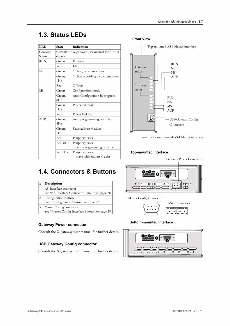
1.3. Status LEDs
1.4. Connectors & Buttons
Gateway Power connector
Consult the X-gateway user manual for further details.
USB Gateway Config connector
Consult the X-gateway user manual for further details.
LED State Indication
Gateway Status
Consult the X-gateway user manual for further details.
RUN Green Running
Red Idle
NS Green Online, no connections
Green, 1Hz
Online according to configuration
Red Offline
MS Green Configuration mode
Green, 8Hz
Auto Configuration in progress
Green, 1Hz
Protected mode
Red Power Fail bus
AUP Green, 8Hz
Auto programming possible
Green, 1Hz
Slave address 0 exists
Red Periphery error
Red, 8Hz Periphery error- auto-programming possible
Red,1Hz Periphery error- slave with address 0 exist
# Description
1 AS-Interface connectorSee “AS-Interface Connector Pinout” on page 28.
2 Configuration Button See “Configuration Button” on page 27.)
3 Master Config connectorSee “Master Config Interface Pinout” on page 28.
Top-mounted AS-I Master interface
Bottom-mounted AS-I Master interface
RUNNSMSAUP
Gateway status
Gateway status
USB Gateway Config
Connector
Front View
Top-mounted interface
Bottom-mounted interface
Gateway Power Connector
RUNNSMSAUP
1 1
32
1
1 12 2
5
96
Master Config ConnectorAS-i Connectors
1 1
32

Doc: HMSI-27-256, Rev: 2.20 X-Gateway Interface Addendum: ASI Master
Chapter 2
2. Installation and Configuration
2.1. Gateway Config Interface
The X-Gateway and the AS Interface may be configured by using the software tool Anybus Configu-ration Manager (ACM), which is available from www.anybus.com/support
When ACM is connected to the gateway via the USB configuration connector, the following settings are available:
See also...
• The Anybus X-gateway User Manual, for full details on using ACM.
• The online help in ACM, for further help on the available settings.
Installation and Configuration 2-9
Doc: HMSI-27-256, Rev: 2.20 X-Gateway Interface Addendum: ASI Master
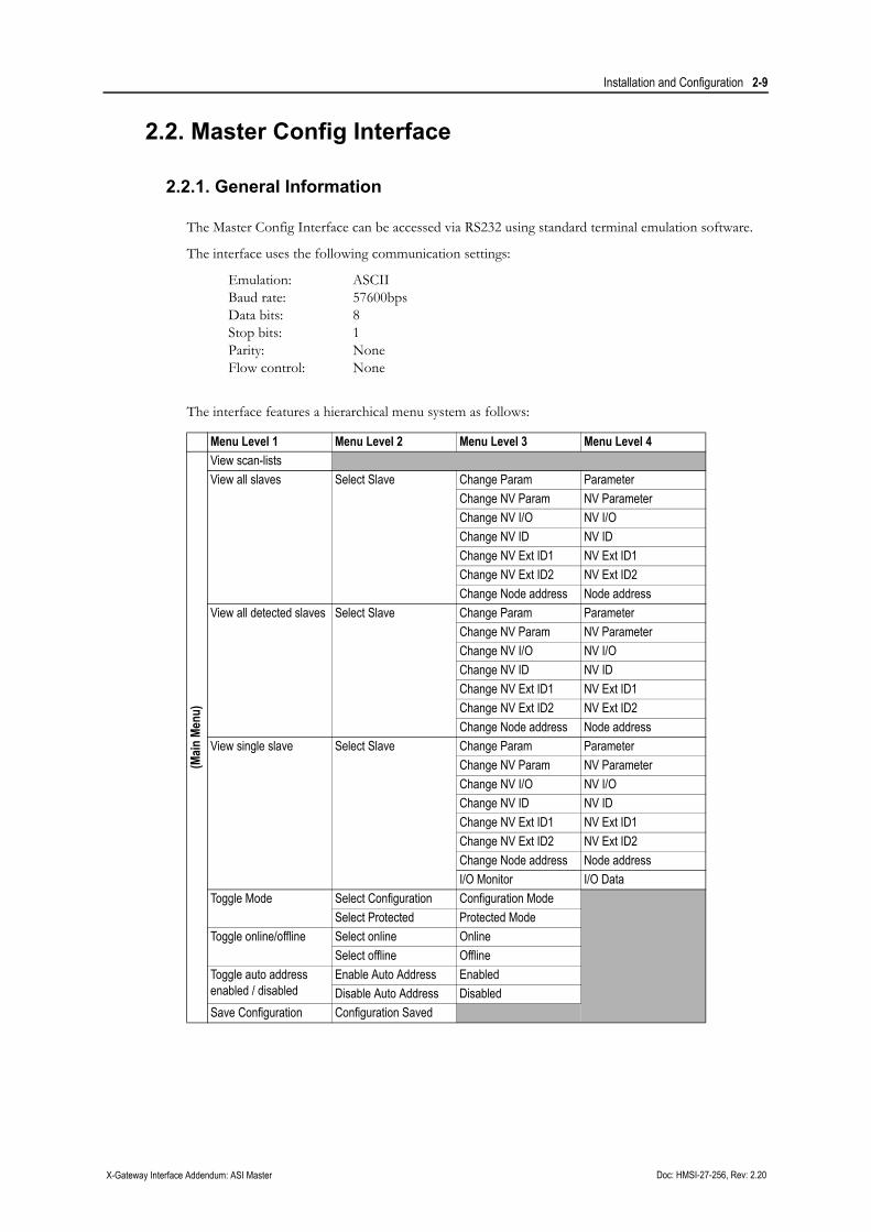
2.2. Master Config Interface
2.2.1. General Information
The Master Config Interface can be accessed via RS232 using standard terminal emulation software.
The interface uses the following communication settings:
Emulation: ASCIIBaud rate: 57600bpsData bits: 8Stop bits: 1Parity: NoneFlow control: None
The interface features a hierarchical menu system as follows:
Menu Level 1 Menu Level 2 Menu Level 3 Menu Level 4
(Main
Men
u)
View scan-lists
View all slaves Select Slave Change Param Parameter
Change NV Param NV Parameter
Change NV I/O NV I/O
Change NV ID NV ID
Change NV Ext ID1 NV Ext ID1
Change NV Ext ID2 NV Ext ID2
Change Node address Node address
View all detected slaves Select Slave Change Param Parameter
Change NV Param NV Parameter
Change NV I/O NV I/O
Change NV ID NV ID
Change NV Ext ID1 NV Ext ID1
Change NV Ext ID2 NV Ext ID2
Change Node address Node address
View single slave Select Slave Change Param Parameter
Change NV Param NV Parameter
Change NV I/O NV I/O
Change NV ID NV ID
Change NV Ext ID1 NV Ext ID1
Change NV Ext ID2 NV Ext ID2
Change Node address Node address
I/O Monitor I/O Data
Toggle Mode Select Configuration Configuration Mode
Select Protected Protected Mode
Toggle online/offline Select online Online
Select offline Offline
Toggle auto addressenabled / disabled
Enable Auto Address Enabled
Disable Auto Address Disabled
Save Configuration Configuration Saved

Installation and Configuration 2-10
Doc: HMSI-27-256, Rev: 2.20 X-Gateway Interface Addendum: ASI Master
2.2.2. Invoking the Configuration Interface
When the interface detects a connection on the Master Config Interface, the following message is dis-played.
------------------------------------------------------ Press Enter for configuration menu------------------------------------------------------ NOTE: I/O exchange will be halted------------------------------------------------------
To open the Configuration Interface, press <Enter>.
2.2.3. Main Menu
The main menu holds the following menu entries.
Menu Command DescriptionView scan-lists Display AS-i scan lists
View all slaves Display all slaves together with their actual configuration(Note that only detected slaves contain configuration information)
View all detected slaves Display all detected slaves together with their actual configuration
View single slave Display the actual and permanent configuration of a specified slave
Toggle Mode Toggle between Protected Mode and Configuration Mode
Toggle online/offline Toggle between online / offline status
Toggle auto address enabled / disabled Enable / Disable automatic slave 0 addressing
Save Configuration Store actual configuration in EEPROM and use as permanent configuration
Anybus-M AS-i Main Menu---------------------------------------------------------- 1 - View scan-lists 2 - View all slaves 3 - View all detected slaves 4 - View single slave 5 - Toggle Protected/Configuration 6 - Toggle Online/Offline 7 - Toggle auto addressing On/Off 8 - Save configuration---------------------------------------------------------- Offline phase active: False Power fail: False Normal operation: True Slave 0 exists: False Configuration match: False Periphery fault: False Address collision: False EEPROM status: Ok Auto address enable: On Auto address assign: False Offline mode: Online Autoprogramming: Not possible Operation mode: Configuration>
This section reflects the state of the AS-i flag bytes. For more information, con-sult the AS-i Specification.

Installation and Configuration 2-11
Doc: HMSI-27-256, Rev: 2.20 X-Gateway Interface Addendum: ASI Master
2.2.4. View Scanlists
This menu displays an overview of the state of the slaves on the AS-Interface network as follows:
------------------------------------------------------ Anybus-M AS-i View Scan-lists------------------------------------------------------------------------------------------------------------ Detected Slaves 0 1 2 3 4 5 6 7 8 9 10 11 12 13 14 15 - - - - - - - - - - - - - - - - 16 17 18 19 20 21 22 23 24 25 26 27 28 29 30 31 - - - - - - - - - - - - - - - - 32 33 34 35 36 37 38 39 40 41 42 43 44 45 46 47 - - - - - - - - - - - - - - - - 48 49 50 51 52 53 54 55 56 57 58 59 60 61 62 63 - - - - - - - - - - - - - - - - Configured Slaves 0 1 2 3 4 5 6 7 8 9 10 11 12 13 14 15 - - - - - - - - - - - - - - - - 16 17 18 19 20 21 22 23 24 25 26 27 28 29 30 31 - - - - - - - - - - - - - - - - 32 33 34 35 36 37 38 39 40 41 42 43 44 45 46 47 - - - - - - - - - - - - - - - - 48 49 50 51 52 53 54 55 56 57 58 59 60 61 62 63 - - - - - - - - - - - - - - - X Activated Slaves 0 1 2 3 4 5 6 7 8 9 10 11 12 13 14 15 - - - - - - - - - - - - - - - - 16 17 18 19 20 21 22 23 24 25 26 27 28 29 30 31 - - - - - - - - - - - - - - - - 32 33 34 35 36 37 38 39 40 41 42 43 44 45 46 47 - - - - - - - - - - - - - - - - 48 49 50 51 52 53 54 55 56 57 58 59 60 61 62 63 - - - - - - - - - - - - - - - - List of periphery faulted slaves 0 1 2 3 4 5 6 7 8 9 10 11 12 13 14 15 - - - - - - - - - - - - - - - - 16 17 18 19 20 21 22 23 24 25 26 27 28 29 30 31 - - - - - - - - - - - - - - - - 32 33 34 35 36 37 38 39 40 41 42 43 44 45 46 47 - - - - - - - - - - - - - - - - 48 49 50 51 52 53 54 55 56 57 58 59 60 61 62 63 - - - - - - - - - - - - - - - ->
- : No slave presentx : Slave present

Installation and Configuration 2-12
Doc: HMSI-27-256, Rev: 2.20 X-Gateway Interface Addendum: ASI Master
2.2.5. View All Slaves
This menu displays the I/O configuration, ID codes etc. for each slave on the network.
------------------------------------------------------ Anybus-M AS-i View All Slaves------------------------------------------------------ Select slave to view (dec) Back - Esc------------------------------------------------------ Slave 0 1 2 3 4 5 6 7 8 9 10 11 12 13 14 15 I/O - - - - - - - - - - - - - - - - ID - - - - - - - - - - - - - - - - Param - - - - - - - - - - - - - - - - Slave 16 17 18 19 20 21 22 23 24 25 26 27 28 29 30 31 I/O - - - - - - - - - - - - - - - - ID - - - - - - - - - - - - - - - - Param - - - - - - - - - - - - - - - - Slave 32 33 34 35 36 37 38 39 40 41 42 43 44 45 46 47 I/O - - - - - - - - - - - - - - - - ID - - - - - - - - - - - - - - - - Param - - - - - - - - - - - - - - - - Slave 48 49 50 51 52 53 54 55 56 57 58 59 60 61 62 63 I/O - - - - - - - - - - - - - - - - ID - - - - - - - - - - - - - - - - Param - - - - - - - - - - - - - - - ->
To alter the settings for a particular slave, enter the slave address and press <Enter>.
2.2.6. View Detected Slaves
This menu displays all detected slaves on the AS-Interface network.
------------------------------------------------------ Anybus-M AS-i View All Detected Slaves------------------------------------------------------ Select slave to view (dec) Back - Esc------------------------------------------------------
Slave ID I/O ID1 ID2 Param>
To alter the settings for a particular slave, enter the slave address and press <Enter>.
2.2.7. View Single Slave
This menu provides access to the settings of an individual AS-Interface slave.
------------------------------------------------------ Anybus-M AS-i View single slave------------------------------------------------------ Enter slave number (dec)------------------------------------------------------
To view or alter the settings for a particular slave, enter the slave address and press <Enter>.

Installation and Configuration 2-13
Doc: HMSI-27-256, Rev: 2.20 X-Gateway Interface Addendum: ASI Master
2.2.8. Toggle Mode
This menu is used when switching between Protected- and Configuration Mode.
------------------------------------------------------ Anybus-M AS-i Toggle Protected/Configuration------------------------------------------------------ 1 - Configuration 2 - Protected------------------------------------------------------
Module in configuration mode
Specify the mode of operation or press <ESC> to cancel.
2.2.9. Toggle Online / Offline Mode
This menu is used when switching between online- and offline mode.
------------------------------------------------------ Anybus-M AS-i Toggle Online/Offline------------------------------------------------------ 1 - Offline 2 - Online------------------------------------------------------
AS-i bus online
Specify the mode of operation or press <ESC> to cancel.
Installation and Configuration 2-14
Doc: HMSI-27-256, Rev: 2.20 X-Gateway Interface Addendum: ASI Master
2.2.10. Auto Address
This menu is used when enabling/disabling the automatic address programming feature.
------------------------------------------------------ Anybus-M AS-i Toggle Auto address On/Off------------------------------------------------------ 1 - Auto addressing On 2 - Auto addressing Off------------------------------------------------------
Auto addressing enabled
Specify the mode of operation or press <ESC> to cancel.
2.2.11. Save Configuration
This menu is used when storing the current configuration in non-volatile memory.
------------------------------------------------------ Anybus-M AS-i Save configuration------------------------------------------------------ Press Enter to save configuration------------------------------------------------------
Press <Enter> to store the current configuration, or <ESC> to cancel.
Note: Saving the configuration is not permitted in Protected Mode.
Installation and Configuration 2-15
Doc: HMSI-27-256, Rev: 2.20 X-Gateway Interface Addendum: ASI Master
2.2.12. Slave Settings
The following menu appears when altering the settings for a particular slave (main menu entries 1... 4).
------------------------------------- Select value to change------------------------------------- 1 - Change Parameter 2 - Change NV Parameter 3 - Change NV I/O 4 - Change NV ID 5 - Change NV Ext ID1 6 - Change NV Ext ID2 7 - Change Node address-------------------------------------
Values for node number: 45
I/O f NV I/O f ID f NV ID f ID1 f NV ID1 f ID2 f NV ID2 f Param f NV Param f>
To alter a particular setting, enter the corresponding digit and press <Enter>. An additional menu ap-pears, allowing the specified setting to be altered. Specify the new value and press <Enter>.
------------------------------------- Change Parameter------------------------------------- Enter new value Back - Esc-------------------------------------
Value for node number: 45
Old value f>
Doc: HMSI-27-256, Rev: 2.20 X-Gateway Interface Addendum: ASI Master
Chapter 3
3. Data Exchange
3.1. General Information
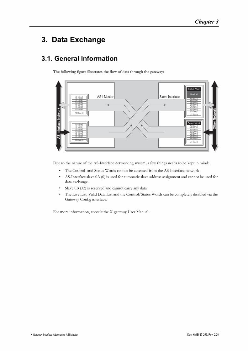
The following figure illustrates the flow of data through the gateway:
Due to the nature of the AS-Interface networking system, a few things needs to be kept in mind:
• The Control- and Status Words cannot be accessed from the AS-Interface network
• AS-Interface slave 0A (0) is used for automatic slave address assignment and cannot be used for data exchange.
• Slave 0B (32) is reserved and cannot carry any data.
• The Live List, Valid Data List and the Control/Status Words can be completely disabled via the Gateway Config interface.
For more information, consult the X-gateway User Manual.
Slave InterfaceAS-I Master
Othe
rNet
work
Status Word
Live List
Control Word
AS-In
terfa
ceNe
twor
k
AS-I Slave 2AS-I Slave 3AS-I Slave 4AS-I Slave 5AS-I Slave 6AS-I Slave 7
...AS-I Slave 63
AS-I Slave 0AS-I Slave 1AS-I Slave 2
AS-I Slave 3AS-I Slave 4AS-I Slave 5AS-I Slave 6AS-I Slave 7
...AS-I Slave 63
AS-I Slave 0AS-I Slave 1
AS-I Slave 2AS-I Slave 3AS-I Slave 4AS-I Slave 5AS-I Slave 6AS-I Slave 7
AS-I Slave 63
AS-I Slave 0AS-I Slave 1
AS-I Slave 2AS-I Slave 3AS-I Slave 4AS-I Slave 5AS-I Slave 6AS-I Slave 7
...AS-I Slave 63
AS-I Slave 0AS-I Slave 1

Data Exchange 3-17
Doc: HMSI-27-256, Rev: 2.20 X-Gateway Interface Addendum: ASI Master
3.2. Data Format
3.2.1. General Information
The following data is forwarded to/from the other network side:
• Input Buffer
- Status Word (Consult the user manual for further information)
- Live List (See “Live List” on page 19.)
- Valid Data List (See “Valid Data List” on page 20.)
- Input Data Image (See “Digital I/O Image” on page 17.)
- Analog Input Image (See “Analog I/O” on page 19.)
• Output Buffer
- Control Word (See “Control & Status Word Implementation” on page 23.)
- Output Data Image (See “Digital I/O Image” on page 17.)
- Analog Output Image (See “Analog I/O” on page 19.)
Note: The Control- and Status Words are not represented on the AS-Interface side.
3.2.2. Digital I/O Image
AS-Interface is nibble-oriented; each slave carries 4 bits in each direction. This is reflected in the Digital I/O block, where data can be represented either in packed (nibble) mode or in byte-mode. The former packs the data of two slaves into a single byte, while the latter assigns a full byte to each slave (in such case, the upper 4 bits will not carry any data).
Since most other networks are either byte- or word-oriented; this must be taken in account when setting up the network communication.
• Byte Mode (Default)
(The data is located in the lower nibble of each byte)
Offset Slave no.0... 7 0 1 2 3 4 5 6 7
8... 15 8 9 10 11 12 13 14 15
16... 23 16 17 18 19 20 21 22 23
24... 31 24 25 26 27 28 29 30 31
32... 39 - 1B 2B 3B 4B 5B 6B 7B
40... 47 8B 9B 10B 11B 12B 13B 14B 15B
48... 55 16B 17B 18B 19B 20B 21B 22B 23B
56... 63 24B 25B 26B 27B 28B 29B 30B 31B

Data Exchange 3-18
Doc: HMSI-27-256, Rev: 2.20 X-Gateway Interface Addendum: ASI Master
• Nibble Mode
(Even slaves = low nibble, odd slaves = high nibble)
Note: Slaves 0A (0) and 0B (32) are reserved for special purposes and does not carry any data.
Offset Slave no.0... 7 1 0 3 2 5 4 7 6 9 8 11 10 13 12 15 14
8... 15 17 16 19 18 21 20 23 22 25 24 27 26 29 28 31 30
16... 23 1B - 3B 2B 5B 4B 7B 6B 9B 8B 11B 10B 13B 12B 15B 14B
24... 31 17B 16B 19B 18B 21B 20B 23B 22B 25B 24B 27B 26B 29B 28B 31B 30B

Data Exchange 3-19
Doc: HMSI-27-256, Rev: 2.20 X-Gateway Interface Addendum: ASI Master
3.2.3. Analog I/O
The Analog I/O block holds data exchanged over Combined Transaction Types 1... 5.
The actual layout of this block depends on the profile of each slave.
Example:
See also...
• 3-20 “Valid Data List”
3.2.4. Live List
The Live List is an 8-byte bitfield which holds the active status of each slave on the AS-Interface net-work.
Note: The Live List can be disabled through the Gateway Configuration Interface.
Offset Word no. Description0... 1 1 Analog Input Data for slave 1, channel 0
2... 3 2 Analog Input Data for slave 1, channel 1
4... 5 3 Analog Input Data for slave 1, channel 2
6... 7 4 Analog Input Data for slave 1, channel 3
8... 9 5 Analog Input Data for slave 2, channel 0
10... 11 6 Analog Input Data for slave 2, channel 1
12... 13 5 Analog Input Data for slave 2B, channel 0
14... 15 6 Analog Input Data for slave 2B, channel 1
... ... ...
246... 247 124 Analog Input Data for slave 31, channel 3

Data Exchange 3-20
Doc: HMSI-27-256, Rev: 2.20 X-Gateway Interface Addendum: ASI Master
3.2.5. Valid Data List
The Valid Data List indicates the validity of each analog/transparent (CTT) data channel through a sin-gle bit, and is refreshed every 5ms.
Note: The Valid Data List can be disabled through the Gateway Configuration Interface.
See also...
• 3-19 “Analog I/O”
Offset: b7 (MSB) b6 b5 b4 b3 b2 b1 b0 (LSB)0 Slave:
2:3/2B:1Slave:2:2/2B:0
Slave:2:1/2A:1
Slave:2:0/2A:0
Slave:1:3/1B:1
Slave:1:2/1B:0
Slave:1:1/1A:1
Slave:1:0/1A:0
1 Slave:4:3/4B:1
Slave:4:2/4B:0
Slave:4:1/4A:1
Slave:4:0/4A:0
Slave:3:3/3B:1
Slave:3:2/3B:0
Slave:3:1/3A:1
Slave:3:0/3A:0
2 Slave: 6:3/6B:1
Slave: 6:2/6B:0
Slave:6:1/ 6A:1
Slave: 6:0/6A:0
Slave: 5:3/5B:1
Slave: 5:2/5B:0
Slave: 5:1/5A:1
Slave:5:0/5A:0
3 Slave: 8:3/8B:1
Slave: 8:2/8B:0
Slave 8:1/ 8A:1
Slave: 8:0/8A:0
Slave: 7:3/7B:1
Slave: 7:2/7B:0
Slave: 7:1/7A:1
Slave: 7:0/7A:0
4 Slave: 10:3/10B:1
Slave: 10:2/10B:0
Slave: 10:1/10A:1
Slave: 10:0/10A:0
Slave: 9:3/9B:1
Slave: 9:2/9B:0
Slave: 9:1/9A:1
Slave: 9:0/9A:0
5 Slave: 12:3/12B:1
Slave: 12:2/12B:0
Slave: 12:1/12A:1
Slave: 12:0/12A:0
Slave: 11:3/11B:1
Slave: 11:2/11B:0
Slave: 11:1/11A:1
Slave: 11:0/11A:0
6 Slave: 14:3/14B:1
Slave: 14:2/14B:0
Slave: 14:1/14A:1
Slave: 14:0/14A:0
Slave: 13:3/13B:1
Slave: 13:2/13B:0
Slave: 13:1/13A:1
Slave: 13:0/13A:0
7 Slave: 16:3/16B:1
Slave: 16:2/16B:0
Slave: 16:1/16A:1
Slave: 16:0/16A:0
Slave: 15:3/15B:1
Slave: 15:2/15B:0
Slave: 15:1/15A:1
Slave: 15:0/15A:0
8 Slave: 18:3/18B:1
Slave: 18:2/18B:0
Slave: 18:1/18A:1
Slave: 18:0/18A:0
Slave: 17:3/17B:1
Slave: 17:2/17B:0
Slave: 17:1/17A:1
Slave: 17:0/17A:0
9 Slave: 20:3/20B:1
Slave: 20:2/20B:0
Slave: 20:1/20A:1
Slave: 20:0/20A:0
Slave: 19:3/19B:1
Slave: 19:2/19B:0
Slave: 19:1/19A:1
Slave: 19:0/19A:0
10 Slave: 22:3/22B:1
Slave: 22:2/22B:0
Slave: 22:1/22A:1
Slave: 22:0/22A:0
Slave: 21:3/21B:1
Slave: 21:2/21B:0
Slave: 21:1/21A:1
Slave: 21:0/21A:0
11 Slave: 24:3/24B:1
Slave: 24:2/24B:0
Slave: 24:1/24A:1
Slave: 24:0/24A:0
Slave: 23:3/23B:1
Slave: 23:2/23B:0
Slave: 23:1/23A:1
Slave: 23:0/23A:0
12 Slave: 26:3/26B:1
Slave: 26:2/26B:0
Slave: 26:1/26A:1
Slave: 26:0/26A:0
Slave: 25:3/25B:1
Slave: 25:2/25B:0
Slave: 25:1/25A:1
Slave: 25:0/25A:0
13 Slave: 28:3/28B:1
Slave: 28:2/28B:0
Slave: 28:1/28A:1
Slave: 28:0/28A:0
Slave: 27:3/27B:1
Slave: 27:2/27B:0
Slave: 27:1/27A:1
Slave: 27:0/27A:0
14 Slave: 30:3/30B:1
Slave: 30:2/30B:0
Slave: 30:1/30A:1
Slave: 30:0/30A:0
Slave: 29:3/29B:1
Slave: 29:2/29B:0
Slave: 29:1/29A:1
Slave: 29:0/29A:0
15 - - - - Slave: 31:3/31B:1
Slave: 31:2/31B:0
Slave: 31:1/31A:1
Slave: 31:0/31A:0
16a
a. See 3-24 “Status Flags 1 (698h, RO)”
ASI Flag 7 ASI Flag 6 ASI Flag 5 ASI Flag 4 ASI Flag 3 ASI Flag 2 ASI Flag 1 ASI Flag 0
17b
b. See 3-24 “Status flags 2 (699h, RO)”
ASI Flag 15 ASI Flag 14 ASI Flag 13 ASI Flag 12 ASI Flag 11 ASI Flag 10 ASI Flag 9 ASI Flag 8

Data Exchange 3-21
Doc: HMSI-27-256, Rev: 2.20 X-Gateway Interface Addendum: ASI Master
3.3. Configuration Examples
3.3.1. Input Data
The following examples illustrates how data from the AS-Interface network appears on the other net-work side.
Example A:
Live List= EnabledValid Data List= EnabledControl & Status Word= EnabledData Representation= Byte Mode
Example B:
Live List= DisabledValid Data List= DisabledControl & Status Word= EnabledData Representation= Byte Mode
Status Word (2 bytes)
Live List (8 bytes)
Valid Data List (18 bytes)
Analog Data (248 bytes)
(Slave 0A)Slave 1ASlave 2ASlave 3A
Slave 29B......
Slave 30BSlave 31B
340 b
ytes (
170 w
ords
)
(low nibble)(high nibble)
Status Word (2 bytes)
Analog Data (248 bytes)
Slave 8A
Slave 27BSlave 28BSlave 29B
...
(Slave 0A)Slave 1ASlave 2ASlave 3A
...Slave 4ASlave 5ASlave 6ASlave 7A
...
Slave 30BSlave 31B
314 b
ytes (
157 w
ords
)
(low nibble)(high nibble)

Data Exchange 3-22
Doc: HMSI-27-256, Rev: 2.20 X-Gateway Interface Addendum: ASI Master
3.3.2. Output Data
The following examples illustrate how the gateway interprets data from the other network, and forwards information to the slaves on the AS-Interface network.
Example A:
Live List= N/AValid Data List= N/AControl & Status Word= DisabledData Representation= Nibble Mode
Example B:
Live List= N/AValid Data List= N/AControl & Status Word= EnabledData Representation= Byte Mode
Analog Data (32 bytes)
Slave 16A
Slave 22BSlave 24BSlave 26B
...
Slave 3ASlave 4ASlave 6A
...
Slave 8ASlave 10ASlave 12ASlave 14A
Slave 20ASlave 18A
...
Slave 28BSlave 30B
Slave 17A
Slave 23BSlave 25BSlave 27B
(Slave 0A)Slave 2ASlave 5ASlave 7ASlave 9ASlave 11ASlave 13ASlave 15A
Slave 21ASlave 19A
Slave 29B
64 by
tes
(low nibble)(high nibble)
Slave 31B
Slave 1ASlave 3A Slave 2A
Slave 27B......
Slave 28BSlave 29B
Control Word (2 bytes)
Slave 8A
(Slave 0A)Slave 1ASlave 2ASlave 3A
...Slave 4ASlave 5ASlave 6ASlave 7A
Slave 12A
Slave 9ASlave 10ASlave 11A
Slave 16A
Slave 13ASlave 14ASlave 15A
Slave 19A
Slave 17ASlave 18A
64 by
tes
(low nibble)(high nibble)
Data Exchange 3-23
Doc: HMSI-27-256, Rev: 2.20 X-Gateway Interface Addendum: ASI Master
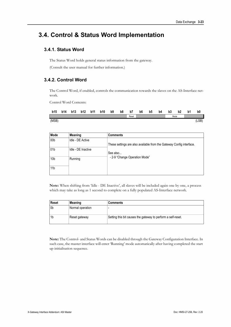
3.4. Control & Status Word Implementation
3.4.1. Status Word
The Status Word holds general status information from the gateway.
(Consult the user manual for further information.)
3.4.2. Control Word
The Control Word, if enabled, controls the communication towards the slaves on the AS-Interface net-work.
Control Word Contents:
Note: When shifting from ‘Idle - DE Inactive’, all slaves will be included again one by one, a process which may take as long as 1 second to complete on a fully populated AS-Interface network.
Note: The Control- and Status Words can be disabled through the Gateway Configuration Interface. In such case, the master interface will enter ‘Running’ mode automatically after having completed the start up initialisation sequence.
b15 b14 b13 b12 b11 b10 b9 b8 b7 b6 b5 b4 b3 b2 b1 b0Reset Mode
(MSB) (LSB)
Mode Meaning Comments00b Idle - DE Active
These settings are also available from the Gateway Config interface.
See also...- 2-9 “Change Operation Mode”
01b Idle - DE Inactive
10b Running
11b
Reset Meaning Comments0b Normal operation -
1b Reset gateway Setting this bit causes the gateway to perform a self-reset.

Data Exchange 3-24
Doc: HMSI-27-256, Rev: 2.20 X-Gateway Interface Addendum: ASI Master
3.5. AS-I Status Flags
3.5.1. Status Flags 1 (698h, RO)
For more information, please consult the AS-i Specification.
3.5.2. Status flags 2 (699h, RO)
For more information, please consult the AS-i Specification.
Bit Content Comment0 (LSB) Get_Flag_Offline_Ready() Offline phase active
1 Status, Flag = Get_Flag_apf() Voltage on AS-i too low
2 Get_Flag_Normal_Operation_Active() Normal operation
3 Operation Mode 0: Protected mode1: Configuration Mode
4 Get_Flag_Auto_Prog_Available() Automatic address assignment will be processed as soon as a slave with zero address and valid configuration data is connected
5 Auto Address Assign Automatic address assignment possible
6 Get_Flag_LDS.0() Slave with address 0 exists
7 (MSB) Get_Flag_Config_OK() Actual configuration matches configured configuration
Bit Content Comment0 (LSB) Offline mode Offline mode
1 - (reserved)
2 EEPROM OK EEPROM OK
3 Mode = Get_Auto_Address_Enable Automatic addressing enabled (set by the user)
4 Get_Flag_Periphery_OK() Periphery fault detected
5 Address Collision Address collision detected
6 - (reserved)
7 (MSB)

Doc: HMSI-27-256, Rev: 2.20 X-Gateway Interface Addendum: ASI Master
Chapter 4
4. AS-Interface Implementation Details
4.1. General Information
The AS-Interface network interface is implemented according to the AS-i Complete Specification (CS) Version 3.0, rev. 1.
Supported Slave Types
• Standard Slaves
4 bits of I/O in each direction.
• Slaves w. Extended Addressing Mode
3 bits out, 4 bits in, can be configured as A- or B-slaves, allowing up to 62 slaves to be used.
• Slaves w. support for Combined Transactions
Up to 4 analog I/O channels, or other types of I/O which requires one or more bytes of data. The following Combined Transaction types are supported:
Note: The AS-i Master interface does not implement support for the ‘Reset’ and ‘Read Status’ services on individual slaves.
Master Profiles
The master interface supports the following master profiles:
• Profile M3
Full extended master, Combined Transaction type 1.
• Profile M4
Support for Combined Transaction types 2, 3, 4 and 5.
Type Slave Profile Comments
Type 1 S-7.1 (not supported)
Type 1 S-7.2 (not supported)
Type 1 S-7.3 16-bit I/O
Type 1 S-7.4a
a.Acyclic STRING services operating on 7.4 slaves are not supported.
Complex field devices
Type 2 S-7.5.5b
b.‘Issue CTT2 command’ (CTT2_CMD) is not supported
Combi field devices
Type 2 S-7.A.5b Combi field devices
Type 2 S-B.A.5 Serial communication field devices
Type 3 S-7.A.7 4I/4O in extended address mode
Type 3 S-7.A.A 8I/8O in extended address mode
Type 4 S-7.A.8 16-bit inputs in extended address mode
Type 5 S-6.0 High speed 16-bit I/O
Safety at Work S-0.B Safety at Work input slaves
Safety at Work S-7.B Safety at Work input slaves with standard outputs

AS-Interface Implementation Details 4-26
Doc: HMSI-27-256, Rev: 2.20 X-Gateway Interface Addendum: ASI Master
4.2. Network Security
The Master Interface offers two modes of operation related to network security; Configuration Mode and Protected Mode. For network security reasons, certain functions that are available in Configuration Mode are not available in Protected Mode and vice versa.
• Configuration Mode
All slaves attached to the network are active instantly. Automatic slave address assignment is not possible in this mode.
• Protected Mode
Slaves must be detected and configured in order to become active. Automatic slave address as-signment is possible in this mode.
See also...
• 4-27 “Configuration Button”
• 2-13 “Toggle Mode”
4.3. Automatic Slave Address Assignment
This is a powerful feature which allows a failed sensor or actuator to be exchanged without requiring time consuming network con-figuration procedures.
This is a critical procedure which can potentially lead to errors if not cautious. Hence, certain restrictions apply:
• The Master Interface must be running in Protected Mode.
• The network must be projected, i.e. the Master Interface must hold information about the type and address of the slaves in error-free operation.
• Only one slave can be missing in the List of Active Slaves.
• Automatic Slave Addressing must be enabled
• The replacement slave must be of the same type as the failed one, i.e. I/O configuration and ID-code must cor-respond to the permanent configuration data in the Mas-ter Interface.
See also...
• 4.2. Network Security
• 2.2.10. Auto Address
No
No
No
No
No
Yes
Yes
Yes
Yes
Yes
I/O & ID Code= Permanent Config
Data
ChangeSlave 0 Address
Address Changed No Change
Slave 0Available?
Auto AddressEnabled?
One slavemissing?
ProtectedMode?
START
AS-Interface Implementation Details 4-27
Doc: HMSI-27-256, Rev: 2.20 X-Gateway Interface Addendum: ASI Master
4.4. Synchronous Data I/O
The Master interface supports Synchronous Data I/O, which enables synchronous I/O operations for a specific range of slaves on the network. This functionality is based on the concept of exchanging data in the normal cycle, and validating that data based on an additional trigger event.
See also...
• 2-8 “Configuration Settings”
4.5. Configuration Button
The on-board configuration button serves two purposes:
• Mode Change
Pushing the button for less than two seconds causes the master interface to toggle between Con-figuration Mode and Protected Mode.
• Initiate Auto Configuration
Pushing and holding the button for more than five seconds enables Auto Configuration; the master interface will upload the network configuration and save it as the pre-set configuration. This is only permitted in Configuration Mode.
Note: Bus power must be present in order for this functionality to be available.
See also...
• 1-7 “Status LEDs”
• 4-26 “Network Security”
Doc: HMSI-27-256, Rev: 2.20 X-Gateway Interface Addendum: ASI Master
Appendix A
A. Technical Specification
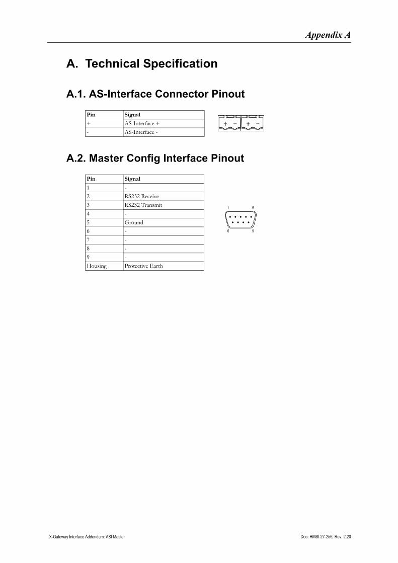
A.1. AS-Interface Connector Pinout
A.2. Master Config Interface Pinout
Pin Signal
+ AS-Interface +
- AS-Interface -
Pin Signal
1 -
2 RS232 Receive
3 RS232 Transmit
4 -
5 Ground
6 -
7 -
8 -
9 -
Housing Protective Earth
1 5
96