x-ray tube for the analysis of … tube for the analysis of crystalstructure by j.e. de graaf and w....
TRANSCRIPT

SEPTEMBER 1938 259
X-RAY TUBE FOR THE ANALYSIS OF CRYSTAL STRUCTURE
by J. E. DE GRAAF and W. J. OOSTERKAMP.
, The following special requirements must be made of an X-ray tube which is intended forthe analysis of crystal structure: the exposure time required must be short, the radiationmust be speetrally pure and the operation of the tube must be easy. A tube with water-cooled anode which satisfies these requirements is described. Special attention is paid tothe shape of focus necessary to obtainthe greatest possible brightness. The problem ofheat conduction connected with the coolingof the anode is dealt with.
There exist in the main two large fields forthe application of X-rays: medicine and the testingof materials. In medicine X-rays are used fordiagnostic and therapeutic purposes, in the testingof materials for detecting macroscopie defects 1)and for studying crystal structure by means ofdiffraction diagrams 2). .The requirements made of the X-ray tube are,
different for each of these two applications. Toname a single example: in certain therapeuticapplications of X-rays, where use is ~ade of theirdestructive effect 'upon tissues, it is of foremostimportance that the rays .possess high penetrationand energy. The shape of the focus (i.e. the spotwhere the X-rays originate). is of less importance;it may he fairly large. In the other applicationsmentioned where it is a question of obtaining animage of internal details or a diffraction diagram,it is very important that the focus be small-for the sake of sharpness of the-image or diffractiondiagram. On the other hand there are also condi-tions which must be kept in mind in the construe-tion of all kinds of X-ray tubes, among others arethe proteetion of the operator against X-rays otherthan those of the beam directed on the object, andthe safeguarding against the high voltages necessaryfor the working of the tubes.
In this article we shall deal with a tube which hasbeen developed especially for use in the analysisof crystal structure, not only in scientific and tech-nicallaboratories, but also in the workshop. For a,detailed description of the procedure in the dif-ferent branches 'of structure analysis (with a singlecrystal according to La ue, with a powder accor-ding to Debye and Sc.lrer r er, ~nvestigation ofstresses, etc.) we refer the reader to the series ofarticles by Burgers 2) .. The various possible ar-rangements all have the common feature that thebeam of X-rays coming from the tube is firstreduced by means of a diaphragm to a narrow ray;
1) See the five articles by J. E. de Graaf on this subjectin the 2nd and 3rd volumes of this periodical.
2) See the twelve articles by W. G. Burgers' on this sub-ject in the 1st and 2nd volumes of this periodical.
621.386.1: 548.73
this ray then falls upon the substance to be exam-ined. It is then deflected or reflected in differentdirections, which are determined by the crystalstructure, and a blackening occurs at correspondingpoints on a photographic film sit~ated at somedistance from the substance (fig. 1). .In the construction of the X-ray tube which
we are about to describe the following points havebeen especially considered:1) The required exposure times must be as short
as possible. This is important not only forroutine work, but also for scientific research,where reasonable exposure times are desirableeven in the case of.poorly reflecting substances orwhen a small opening of the diaphragm is used. '
2) .The radiation must possess a pure spectrum.When this is not the case the undesired spectrumlines themselves give rise to interference images,and in this way make the diagrams much morecomplicated and their interpretation unneces-sarily difficult.
3) The tube must be easily handled and adjusted,especially for industrial purposes.
Fig. 1. Diagram of an arrangement for crystal structureanalysis. A = focus from which the X-rays are emitted, 'D == diaphragm, P = substance, F = film.
Construction of the tube
Fig. 2 is a diagram of the construction of thetube. The hot cathode K emits electrons which areaccelerated by a poténtial difference of 20 to 40kilovolts in the direction 0.£ the anode A. At theanode a small part 0.£ the kinetic energy of theelectrons is transformed into X-radiation, thegreater part, however, into heat. The anode issoldered into a chrome-iron can D, to which theglass part G which bears the cathode is fused. Thisconstruction makes it possible to cool the anode

260 PHILlPS TECHNICAL REVIEW Vol. 3, No. 9
Fig. 2. Construction of the X-ray tube for structure analysis: The anode A is part of thechrome-iron canD, to which is fused the glass part G,which bears the shielding cylinder Bwith the plate C and the cathode K. The X-rays pass through the windows 1. in the direc-tion of the arrowsR. At W the coolingwater flows in and out. The tube is placed in a metalcontainer M which, like the anode and the metal covering of the high tension cable H,is earthed. A lead jacket P surrounds the anode can.
with water, so that an efficient dissipation of heatis attained. The cooling water flowsin and out at W.At L there' are glass windows in the anode can.through which the X-rays are emitted to theoutside. A metal cylinder B kept at cathode po-tential surrounds cathode and anode. The wallof the cylinder has only several small openings forthe passage of the X-rays. In this' way provisionhas been made against secondary electrons fromthe anode being able to bombard the window L.A lead jacket P surrounds the anode can and cap-tures all X-rays except the beam passing throughthe windows.
The anode is earthed, so that it is not necessaryto have an insulated pump with a closed watercircuit for cooling, but water from the mains may
be used. Since the cathode is at high potential(which is supplied via the high tension cable H)the heating current transformer must be insulated.This transformer is built in with the high ten-sion transformer, The whole tube is placed in ametal container M which, like the metal coveringof the high tension cable, is earthed, so' that itis impossible for the user to come into contact withcurrent bearing components. The cathode is mount-ed in the opening of a plate C which is kept atcathode potential. This plate with its opening actsas an electron lens, i;e. it causes such a deflectionin the paths of the electrons 'that they are focussedsharply on the anode, By giving the cathode asuitable form, a focus of given shape and dimensionscan be obtained.
Short exposure times
We shall now discuss the way in which therequirements mentioned at the beginning of this
article are fulfilled. There are various importantfactors in obtaining a short exposure time, forexample, the filter of the tube itself. In order topass from the vac,uum in the tube into the outeratmosphere, the X-rays must inevitably passthrough a wall by which they are weakened.The weakening is kept as small as possible in thetube described by making the windows L (fig. 2) ofLindemann glass, which contains only elementswith a low atomic number and therefore absorbs.only little of the radiation. Moreover, the windowsare very thin, namely 0.12 mm in thickness. Thistype of window was made possible by the above-mentioned proteetion of the windows from bom-bardment by secondary electrons from the anode.The active radiation obtained with a copper anode
R
is weakened only 25 per cent by the windows.Furthermore it is clear that the exposure times
may be chosen shorte~ the closer the camera can heplaced to the focus: the intensity of the radiation isinversely proportional to the square of the distance.The minimum distance is determined by the diam-eter of the tube. This latter is closely connectedwith the maximum voltage to be used, since thedistance between the shielding cylinder B and theanode necessary to avoid breakdown increasesproportionally ,~ith the voltage to be used. In orderto be able to use the tube for L a:u e diagramsalso, where relatively high voltages are necessary,the maximum permissible voltage was fixed at 60kilovolts (for alternating as well as for directvoltage). Nevertheless, because of the compactconstruction of the components in the anode can, thediameter is only 60 mm, so that the camera mayhe brought up to a distance o~ about 35 mm fromthe focus.

SEPTEMBER 1938 X-RAY TUBE FOR CRYSTAL STRUCTURE 261
The most important factors for obtaining shortexpo.sure times are, however, the shape and thebrightness of the focus, The first method thatwould occur to. one, to. increase the intensity of theX-ray beam, would be to. increase the dimensionsof the focus and choose correspondingly greaterdiaphragm openings, This method, however, aswasmentioned in the introduetion. is limited by thelack of sharpness which would result from too largea source of radiation. In general, for making crystalstructure diagrams a diaphragm opening of 1 mmdiameter 3) at the most is used, and it is thereforeuseless to. make the source of radiation much largerthan 1 X 1 mm. When the surface to. be irradiatedis determined, the X-ray energy can only be in-·creased by increasing the brightness of thefocus,
Shape and brightness of the focus. The fact that Xvradiation does not followLambert's law may be utilized in determining theshape of the focus. According to. that law the bright-ness of a radiating surface is the same from all'
I.1 28215
a bFig. 3a) Body radiation. The depth 5 of the emitting layer is
greater than the depth Ä of the layer which con-tributes to the light emitted. Upon normal (1) andoblique (2) direction of observation the same light. intensity is obtained from the same apparent sur-face (d). The brightness is therefore the same in alldirections (Lambert's' law).
b) Surface radiation. In this case 5 < Ä. With obliquedirection of observation (2) the same light intensityis obtained from the apparent surface d sin tp, as isobtained with normal observation (1) of the sur-face d. The brightness in the oblique direction isgreater (I/sin rp times) than that in the normaldirection.
directions, and it is valid in the case of so-calledbody radiation, If one looks normally at the surface,for instance of a volume of incandescent gas of thethickness s [arrow 1, fig. 3a), the outermost layeras well as the deeper layers contrihute to. the lightobserved, The light of the more deeply lying partswill, however, be weakened by absorption, and it
3) For special cases smaller diaphragm openings are also used,0.5 or 0.25 mm.
will be more weakened the more deeply its sourcelies in the gas. After a definite depth (! practicallyno more contribution Fill be made to. the lightleaving the surface. If one looks obliquely at thesurface of the incandescent mass (arrow 2), acolumn of the length cp will again contribute to. theobservation of light, and with the same diameter ofcolumn as in the first case, i.e. from the sameapparent surface, the same light Intensity is ob-tained. This means that the brightness (lightintensity/apparent surface) is the same in bothdirections. From fig. 3a, however, it may be seenimmediately that the above deductions are only.valid for body radiation, i.e. when the depth sof the layer in which the light emitting pro.cessestake place is greater than the depth (! of the layerwhich contributes to. the light leaving the surface,Fig. 3b shows the opposite case, where s < (],i.e. a.surface radiation. The cross hatched areas of thecolumn (whose length is determined only by theabsorption in the substance of the' radiation emit-ted) now contrihute nothing, since no light-emit-ting pro.cesses take place in those areas. When thecolumn has an oblique position that part of itwhich can cause radiation to. be emitted from thesurface becomes longer. If one now considersthe emission from the same real surface, the samelight intensity is obtained in both directions,because the volume of the column which contrih-.utes has remained the same [oblique cylinders withequal bases and equal altitudes). Considering,however, that in the oblique direction the apparentradiating surface is smaller, the brightness in theoblique direction will be greater than in the normaldirection of observation. Fig. 4 shows the depend"ence of brightness on the angle of observation forboth cases, body radiation (I) and surface radiation(II) .In the case of X-rays we are actually concerned
with a surface radiation. The absorption of Xvraysin the material of th~ anode is much less than thatof the bomharding electrons, The electrons exciteX -radiation in only a thin layer(thickness s=O.Olmm,for instance), while the radiation would be
/. \I \
~:• 28216
Fig. 4. Polar diagram. of the brightness with volume radiation(I) and surface radiation (II). At small angles the straightline 11bends toward a circle (Lambert's law, as in I).At still smaller angles the irregularities in the surface of theanode become noticeable and the brightness diminishestoward zero (indicated by dotted line).
262 PHILlPS TECHNICAL REVIEW Vol. 3, No. 9
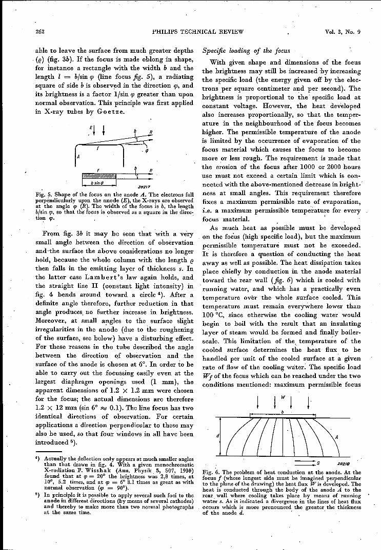
able to leave the surface from much greater depths, (e) (fig. 3b). If the focus is made oblong in shape,for instance a rectangle with the width b and thelength 1 = bjsin cp (line focus jig. 5), a radiatingsquare of side b is observed in the direction cp, andits brightness is a factor ljsin cp greater than uponnormal observation. This principle was first appliedin X-ray tubes by Goetze.
rr:-:1 4 :282/7
Fi~. 5. Shape of the focus on the anode A. The electrons fallperpendicularly upon the anode (E), the X-rays are observedat the angle tp (R). The width of the focus is b, the lengthbfsin tp; so that the' focus is observed as a square in the direc-tion cp. '
From fig. 3b it may be seen that with a verysmall angle between the direction, of observationand ·the surface the above considerations no longerhold, because the whole column with the length ethen falls in the emitting layer of thickness s. Inthe latter case Lambert's law again holds, andthe straight line II (constant light, intensity) infig. 4 bends around toward a circle 4). After adefinite angle therefore, further reduction in thatangle produces, no further increase in brightness.Moreover, at small angles to the surface slightirregularities in the anode (due to the rougheningof the surface, see below) have a disturbing effect.For these reasons in the tube described the anglebetween the direction of observation and thesurface of the anode is chosen at 6°. In order to heable to carry out the focussing easily even at thelargest diaphragm openings used (1 mm), theapparent dimensions of 1.2 X 1.2 mm were chosenfor the focus; the actual dimensions are therefore1.2 X 12 mm (sin 6° ~ 0.1). The line focus has twoidentical directions of observation. For certainapplications a direction perpendicular to these mayalso be used, so that four windows in all have beenintroduced 5).
4) Actually the deflectiononly appears at much smaller anglesthan that drawn in fig. 4. With a given monochromaticX-radiation F. Wisshak (Ann. Physik, 5, 507, 1930)found that at cp = 20° the brightness was 2,8 times, at10°, 5.2 times, and at p = 6° 8.1 times as great as withnormal observation (p = 90°).
5) In principle it is possible to apply several such foci to theanode in different directions (by means of several cathodes)and thereby to make more than two normal photographsat the same time.
Specific loading of the focus
With given shape and dimensions of the focusthe brightness may still be increased 'by increasingthe specific load (the energy given off by the elec-trons per square centimeter and per second). Thebrightness is proportional to the specific load atconstant voltage. However, the heat developedalso increases proportionally, so that the temper-ature in the neighbourhood of the focus becomeshigher. The permissible temperature of the anodeis limited by the occurrence of evaporation of thefocus material which causes the focus to becomemore or less rough. The requirement is made thatthe e~osion of the focus after 1000 or 2000 hoursuse must not exceed a certain limit which is con-nected with the above-mentioned decrease in bright- 'ness at small angles. This requirement thereforefixes a maximum permissible rate of evaporation,i.e. a maximum permissible tempeï:ature for everyfocus material. I,
As much heat as possible must be developedon the focus (high specific load), but the maximumpermissible temperat.ure must not be exceeded.It is therefore a question of conducting the heataway as well as possible. The heat dissipation takesplace chiefly by conduction in the anode materialtoward the rear wall (jig. 6) which is cooled withrunning water, and which has a practically eventemperature over the whole surface cooled. Thistemperature must remain everywhere lower than100 oe, since otherwise the cooling water wouldbegin to boil with the result that an insulatinglayer of steam would be formed and fina~y boiler-scale. This limitation of the. temperature of the'cooled surface determines the heat flux to behandled per unit of the cooled surface at a givenrate of flow of the cooling water, The specific loadWf of the focus which can be reached under the twoconditions mentioned: maximum permissible focus
d
___ 5 282/8
Fig. 6. The problem of heat conduction at the anode. At thefocus f (whose longest side must be imagined perpendicularto the plane of the drawing) the heat flux W is developed. Theheat is conducted through the body of the anode A to therear wall where cooling takes place by means of runningwater s. As is indicated a divergence in the lines of heat fluxoccurs which is more pronounced the greater the thicknessof the anode d. ' '

SEPTEMBER 1938 X-RAY TUBE FOR CRYSTAL STRUCTURE 263
temperature and rnaxrmum permissible densityof heat flux on the cooled surface, depends uponthe thickness d of the anode. At a certain thicknessof the anode the value which may be assumed by Wfreaches a maximum. This may be explained in thefollowing way.
°O~------~--------~2---------3~--d-~-m-)~4
Fig. 7. Dependence of the specific focus loading Wf on thethickness of the anode d, with an infinitely long line focus1.2 mm wide on a copper anode. In curve a the density W.of the heat flux at the cooled surface is at its maximum per-missible value (24 W/sq.mm). In curve b the focus temperatureTr is at its maximum permissible value (300 DC), while the tem-perature of the water-cooled surface is fixed at 100 DC (in thecase of curve a this condition was automatically fulfilled).The "permitted" region is below both curves. The thick-ness d which corresponds to the point of intersection of thecurves is the optimum thickness. The curves are calculatedfor a constant loading (direct current); the maximum valueof Wf attainable, when d = 2 mm, is then 80 W/sq.mm. Whenalternating current of the same effective value is used the at-tainable value of Wf becomes smaller, namely 60 W/sq.mm.
In fig. 7 Wf is plotted against d. Curve a is cal-culated for the case where the density of heatflux Ws is always at its maximum permissiblevalue, which is here assumed to be 24 Wjsq.mm.The temperature of the focus is disregarded incurve a. With a very thin anode (small d) the linesof heat flux run practically parallel to each othertoward the rear wall, i.e. the density of heat fluxis uniform, and ~f may therefore be no greaterthan w.~(24 Wjsq.mm). If the anode is thicker(larger d) a certain divergence of the heat fluxappears in the heat conduction (see the lines offlux in fig. 6), so that the density of the heat fluxis smaller at the rear wall than at the focus. Thepermissible value of Wf therefore becomes greaterthan Ws; in the first approximation it increasesproportionally with d. The region above the curveis "forbidden", because every point in that regionrepresents a combination of Wf and d, where Ws
would be greater than 24 Wjsq.mm. Curve b iscalculated for the case where the focus temperature
Tf is always at its maximum permissible value,which is here taken as 300°C (copper anode). Inthis curve the density of heat flux at the cooledsurface is disregarded but it is assumed that therate of flow of the cooling water is always highenough, so that the cooled surface. maintains atemperature of 100°C. Along the curve thereforethe temperature difference between focus and cooledsurface is constant and equal to 200 °C. At verysmall values of d the temperature gradient, andtherefore also the heat flux in the anode which isproportional to it, must be very great in order thatthe temperature difference between the two sur-faces may reach the figure mentioned. In this casetherefore Wf is very great. At greater values ofd the temperature difference mentioned is attainedwith a smaller gradient and therefore smaller valueof Wf. Here again the region above the curve is"forbidden", since at every point in that regionthe focus temperature would be higher than 300°C.If it is now desired to satisfy bot h conditions,
that for Tf and that for Ws, then only that region is"permitted" which lies not only below curve a,but also below curve b. It is clear that with agiven thickness of anode d, namely that whichcorresponds to the intersection of the two curves, thegreatest specific loading of the focus Wf is attained.This optimum thickness of wall depends upon
the rate of flow of the cooling water, since thisrate of flow determines the permissible densityof heat flux at the rear wall of the anode. Moreoverit is, of course, not the same for different anodematerials with their different physical constants.Since, however, these materials are only appliedin the form of a thin plate to a base of copper, themutual differences between the correspondingoptimum thicknesses of wall are not great. Thethinner the plates applied, the better the heatdissipation and the higher the specific load. In thetube here described the rate of flow of the water is5 mjsec, for which a pressure of 1 atmosphere anda consumption of water of 6 litresjmin. is necessary.The optimum wall thickness is then about 2 mm,and the permissible specific load with a copperanode is 60 Wjsq.mm, when the tube works onalternating voltage and the line focus is 1.2 mm inwidth. For the sake of comparison it may be addedthat with the aircooled "Metalix" tube for struc-tural analysis 6) the specific load is 25 Wjsq.mmand with another watercooled tube 7) 30 Wjsq.mm(both tubes having copper anodes).
6) A. B 0 uwe r sand W. Busse, Z. Krist. 77,507,1931.7) R. Glocker, Materialprüfung mit Röntgenstrahlen, 1936,
p. 167.

264 PHILIPS TECHNICAL REVIEW Vol. 3, No. 9
For iron, cobalt and chromium in the tube de-scribed a specific load of about 35 W jsq.mm is per-missible, for tungsten and molybdenum about70 W jsq.mm, when these metals are soldered to thecopper base of the anode in the form of plates0.5 mm thick.
Homogeneity of the focus loading
Fig. 8 shows the distribution of temperature overthe width of the line focus. In the calculation ofthis curve (as in the curves of fig. 7) the line focus
VTm
-3 -2 -1 o
Fig. 8. Temperature distribution over the focus in the caseof homogeneous loading. At the edges of the focus (x = <5) thetemperature is about 20 per cent lower than in the middle.
is assumed to be infinite in length, which gives asatisfactory approximation. It may be seen fromthe curve that the temperature at the edges of thefocus is about 20 per cent lower than in the middle.This phenomenon, which may be ascribed to thelateral dissipation of heat from the focus to theadjacent anode material, occurs with the homogene-ous loading of the whole surface of the focus whichhas been assumed until now. When, however,the cathode has the form of a spiral the loading ofthe focus is not homogeneous. Equal numbers ofelectrons are emitted per sq.cm of the whole surfaceof the spiral. They are drawn immediately towardthe anode by the strong field. It is reasonable tosuppose that the paths of the electrons which areemitted from parts of the spiral whose tangentsare intercepted by the focus will lie closest to eachother. Therefore the current density is greatestat the outside of the electron beam, and conse-quently the focus is more heavily loaded at theedges than in the middle. Therefore with a cathodein the form of a spiral the temperature distributionover the width of the focus will not have the formshown in fig. 8, but will be more nearly constantover the whole width (it may increase slightlyat the edges). Considering the fact that the tem-perature permissible for the focus material is no-where exceeded, and that nevertheless a higheraverage specific loading is obtained, one might
think that the lack of homogeneity of the focusloading would even be advantageous. In the caseof certain kinds of X-ray tubes for medical diag-nosis use is actually made of this feature. Forcrystal structure analysis, however, non-homo-geneous focus loading is not allowable. When theedges are more heavily loaded they cause separateinterference images due to their greater brightness,and these images are shifted somewhat with respectto each other, so that the impression is given ofsplitting or lack of sharpness of the interferencelines or points. This phenomenon is illustrated infig. 9 by a L a u e diagram 8), in which the loadingof the focus was exceedingly bad
,28103
Fig. 9. A L a u e diagram in which, due to very non-homo-geneous loading of the focus, different mutually displacedinterference images have been formed at the same time. Thisphotograph should be compared with a good L a u e photo-graph, such as given in this periodical 1, 213, 1936.
An ordinary spiral cathode may therefore notbe used, the cathode must have such a form that ahomogeneous loading of the focus is obtained witha temperature distribution like that in fig. 8. Thishas been achieved, in the tube described, by meansof a filament the emitting parts of which lie in asingle plane parallel to the anode. In fig. 10 arephotographs of a focus with non-homogeneousloading and one with homogeneous loading, aswell as their brightness distributions recorded witha microphotometer.
Purity of the spectrum
In the introduction the requirement was men-tioned that the X-ray spectrum produced by thetube must be pure, and reasons were given forthis requirement. The bombarding electrons excite
8) This photograph was kindly supplied by R. Stephenof London.
SEPTEMBER 1938 X-RAY TUBE FOR CRYSTAL STRUCTURE 265
in the anode metal an X-radiation with a continuousspectrum upon which is superposed a spectrumconsisting of a few lines. This line spectrum ischaracteristic of each chemical element. In mostof the applications of the tube, such, for example,
I IJ
28101
[ IJ
28205
Fig. lOa) Photographs of a focus with non-homogeneous (I)and one with homogeneous (IJ) loading. The black-ening is caused by the X-radiation emitted from thefocus.
b) Photometer curves. The perpendicular deviationwith respect to the horizontal zero line is propor-tional to the transmissibility at the successivepoints of a cross section of the photographs in a.Small ordinates thus correspond to heavy blacken-ing and therefore to great X-ray intensity. Withthe non-homogeneously loaded focus (1) the bright-ness at the edges is considerably greater than inthe middle.
as investigation by the Debye-Scherer method,a monochromatic X-radiation must be used. Forevery anode material a filter may be chosen of anelement with a somewhat lower atomic numbersuch that practically only one line of the charac-teristic spectrum is allowed to pass, If the surfaceof the anode is contaminated with another element,this element also emits its own characteristicradiation, which is, however, not entirely absorbedby the filter chosen, so that it is generally impos-sible in such a case to obtain a monochromaticradiation. For the sake of the purity of the spectrum,therefore, it is essential to avoid all contaminationof the surface of the anode.The most commonly occurring contamination
is tungsten evaporated from the cathode. Since theanode is situated close to the cathode to improvethe electron focussing, the evaporating tungstencan easily condense on the anode. At theusual cathode temperature of 2400 OK the rateof evaporation of metallic tungsten is still verylow. If, however, the tube contains water vapourthe glowing tungsten is oxidized and the oxideevaporates much more rapidly than the pure metal.The oxide condenses at a cooler spot (the anode,for example, whose focus temperature is much lowerthan the cathode temperature with most materials),
and is here reduced to the metal again 9). Theoxygen liberated continues to attack more tungstenand makes the process progressive.
Water vapour might occur in the tube as theresult of the liberation of hydrogen from metalparts and its oxidation by any oxide present;moreover, the glass may give off water vapour. Avery rigorous outgassing and evacuation of thetube is therefore necessary. For this reason a getteris used in this tube, as in all "Metalix" tubes, whichrapidly absorbs all gas freed during use. Due tothese precautionary measures the intensity of thetungsten lines in the X-ray spectrum obtainedamounts to only 1 to 2 per cent of that of the de-sired radiation after the tube has been in use for1000 hours.Moreover, a rigorous de-gassing is desirable for
another reason: due to a process similar to the onedescribed above, impurities also have an accelerat-ing action on the evaporation of most of the anodemetals, particularly on copper, so that the surfaceof the anode would become rough more rapidlyif the tube were not well de-gassed.
28102
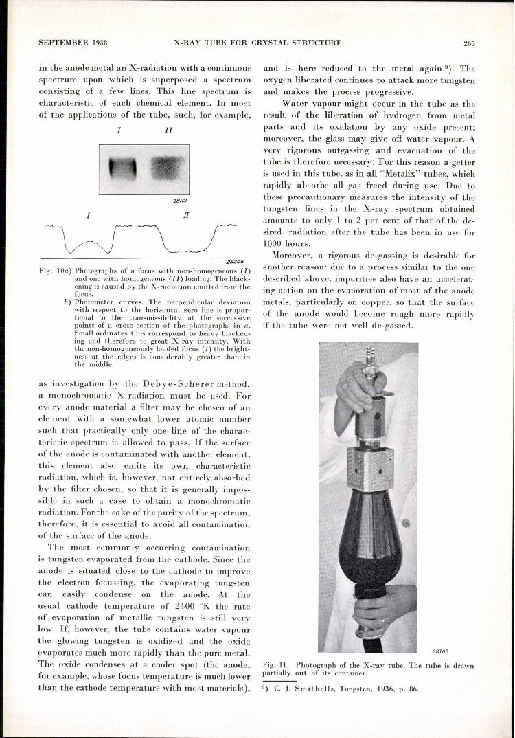
Fig. ll. Photograph of the X-ray tube. The tube is drawnpartially out of its container.
9) C. J. Smithells, Tungsten, 1936, p. 86.

266 PHILlPS TECHNICAL REVIEW Vol. 3, No. 9
A NEW FREQUENCY-CHANGING VALVE
Use of the tubeIn conclusion we shall say a few words about the
practical aspects ofworking with the tube described.The way in which complete protection is obtainedagainst high tension and X-radiation ouside theactive beam has already been discussed. The con-struction with a metal anode can makes it possibleto place the lead jacket immediately around thecan (with a glass tube the lead jacket must be atsome distance from the wall as otherwise it wouldcause a distortion of the field and excessive localincreases in the field strength). The lead jackettherefore need only be short and of small diameter,and the weight of the tube is therefore small. Thishas the advantage that one may work with lightstands and simple suspension arrangements, anda fine adjustment on a definite point of the object
such as is necessary in the measurement of stresses, .is easily and quickly attained. The small size of thetube (see the photograph in fig. 11) also makes forease in manipulation.The characteristics mentioned are desirable in all
X-ray tubes used in technical work. For crystalstructure analysis moreover it is of advantage thatthe tube is quickly replaceable. It is sometimesnecessary to change the type of radiation (i.e. theanode material), in order to adapt its wave length
, to the parameters of the crystal to be investigated.The tube described can be removed from its con-tainer by loosening two screws and may then bereplaced by a tube with a different anode material.The water cooling system is taken out with thefirst tube and then transferred to the second. Inthis way the container remains dry.
by J. L. H. JONKER and A. J. W. M. VAN OVERBEEK.
An octode, i.e. a frequency changer and amplifier valve, is often used as frequency changerin superheterodyne receivers. The octode also serves as oscillator valve for generating theauxiliary frequency. In this article two objections to tbe use of an octode are discussed,namely the··induction effect and the shift in the oscillator frequency when automatic~~" control is employed. The induction effectmay be neutralized in a simple way. In~d"';;""to get rid of the frequency shift a new type of octode has been constructed in thisl~tory in which the oscillator part and the frequency-changing part are practicallyindependent of each other. The construction and characteristics of the new frequencychanger are dealt with in detail.
Introduction
The transformation of the high-frequency os-cillation into an intermediate-frequency oscillationwhich is applied in modern radio receiving sets isoften obtained by means of an ootode. This valvemay be considered as a combination of a triode os-cillator valve with a pentode amplifier valve, as isindicated in fig. 1. The oscillator, consisting of thecathode k and -the grids 1 and 2 delivers a period-ically varying current; as a result of this current,the slope of the pentode changes, or in other wordsthe degree to which the alternating voltage of thecontrol grid 4 of the pentode acts upon the anodecurrent. As one of the results of the action of grids1 and 4 an alternating current component is ob-tained in the anode current, with a frequency equalto the difference between the oscillator frequencyand the signal frequency on grid 4 which we shallcall the signal grid.This system of wave length transformation,
621.385.5 : 621.386.694
when compared 'with other, constructions in whichseparate valves are used for oscillator and fre-
Vit
c
V.z 28220o
Fig. 1.Diagram of the principle of a frequency-changing stagewhen an octode is used. The cathode k with the grids 1 and 2forms an oscillator triode; grids 4, 5 and 6 form, with anode a.an amplifier and frequency-changing pentode. The screengrid 3 is the shield between these two parts of the octode;Vi is the input voltage and Va the output voltage. .