xcellence series - supersonic x208 manual.pdf · 2. the exclamation mark in the triangle indicates...
TRANSCRIPT
XCELLENCE SERIESX208 / X215W / X218W Systems
Pol. Ind. Norte - Perpinyà, 25 08226 TERRASSA (Barcelona-SPAIN)
Copyright © 2012 [email protected] rights reserved www.master-audio.com
Sep 12
User’s manual
ENGLISH
Safety Instructions
1. All safety instructions must be read before using this device.
2. The exclamation mark in the triangle indicates internal components which if replaced can affect safety.
3. The lightning symbol within the triangle indicates the presence of dangerous uninsulated voltages.
4. This device must not be exposed to rain or humidity.
5. Only clean the device with a dry cloth.
6. Do not situate the equipment where its ventilation system might be interfered with.
7. Do not install the device near heat sources such as radiators, heaters or other heat-emitting elements.
8. The equipment must be repaired by qualified technical service personnel when:
A. The mains supply cable is damaged, orB. Any object or liquid has damaged the device; orC. The equipment does not function normally or correctly; or D. The equipment has been exposed to the rain; orE. The chassis is damaged
9. Disconnect the device in the case of electric storms or during long periods of disuse.
10. Never hang the equipment by its handle.
11. Only use manufacturer recommended accessories.
CAUTIONRISK OF ELECTRIC SHOCK
DON’T OPEN
To reduce the risk of fire or electric shock do not expose this equipment to rain or moisture
WARNING:
Master Audio
Xcellence Line Array Series 208.Ver 1.2 Sep 12 3
1. INTRODUCTION
1.1. General product information
Master Audio thank you for the trust placed in our Xcellence loudspeaker systems.
The Line Array Xcellence models combine the benefits of their high quality sound transducers, the convenience of a self-powered system and the flexibility of the DSP (digital system processing) for cabinet control.
More than 38 years’ experience in amplifier and acoustic cabinet design using the highest technology and components come together to give you a product ideal for a multitude of applications, specially those which require high levels of sound pressure and a control of vertical coverage. Stadiums, theatres or big events will become the perfect places for its use.
We suggest you read the following information with attention, assured that it will be of maximum use in helping you to achieve the best results and optimum performance.
1.2. What is a line array?
The trend in sound reinforcement has been to increase both the sound pressure level (SPL) and the size of the audience to be covered. This leads to an increase in the number of cabinets and, as a result of this, an increase in the total size and weight.
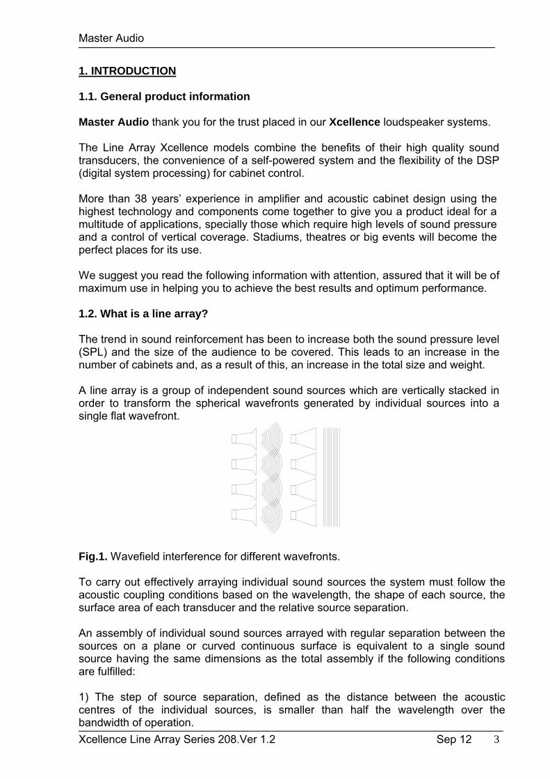
A line array is a group of independent sound sources which are vertically stacked in order to transform the spherical wavefronts generated by individual sources into a single flat wavefront.
Fig.1. Wavefield interference for different wavefronts.
To carry out effectively arraying individual sound sources the system must follow the acoustic coupling conditions based on the wavelength, the shape of each source, the surface area of each transducer and the relative source separation.
An assembly of individual sound sources arrayed with regular separation between the sources on a plane or curved continuous surface is equivalent to a single sound source having the same dimensions as the total assembly if the following conditions are fulfilled:
1) The step of source separation, defined as the distance between the acoustic centres of the individual sources, is smaller than half the wavelength over the bandwidth of operation.
Master Audio
Xcellence Line Array Series 208.Ver 1.2 Sep 12 4
d<= /2
It is not difficult to fulfil this first condition for the low and mid frequencies. For example, two 7" loudspeakers that are separated by 17 cm will reproduce a cylindrical wave up to 1015 Hz.
This condition is difficult to be fulfilled for the high frequencies, as their wavelengths are too small to make the adjacent acoustic centres any smaller than /2. Here comes the second "arrayability" criterion.
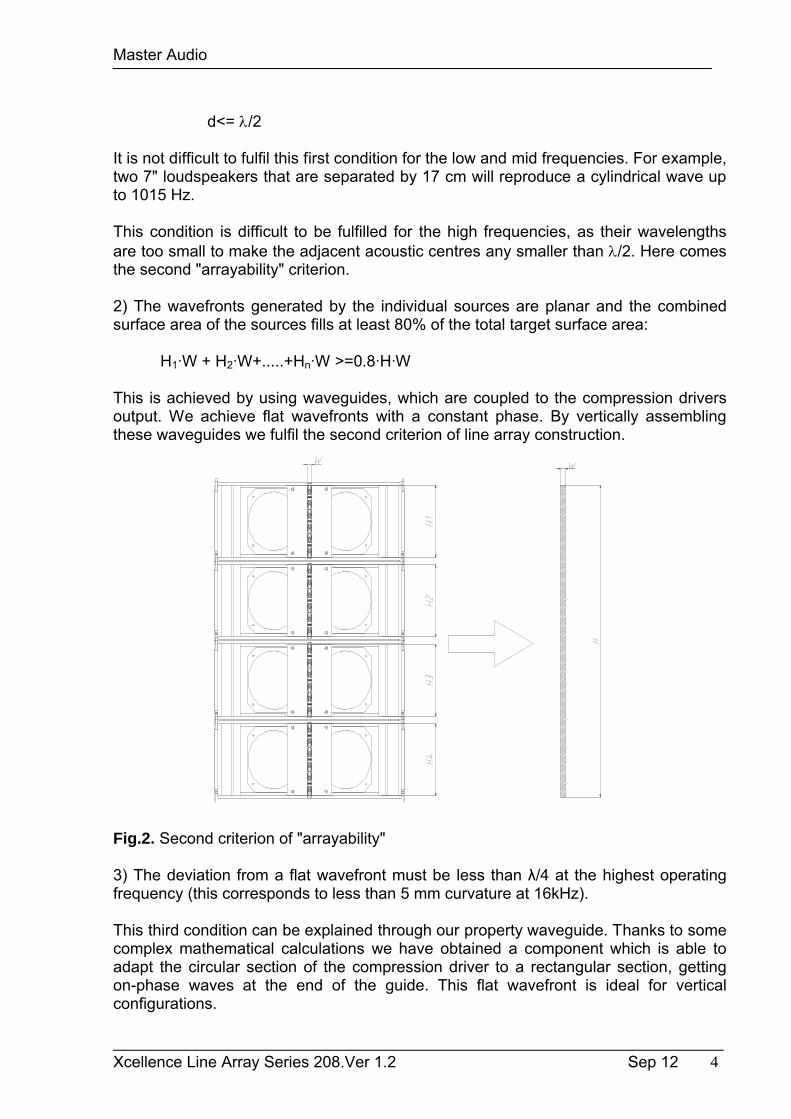
2) The wavefronts generated by the individual sources are planar and the combined surface area of the sources fills at least 80% of the total target surface area:
H1·W + H2·W+.....+Hn·W >=0.8·H·W
This is achieved by using waveguides, which are coupled to the compression drivers output. We achieve flat wavefronts with a constant phase. By vertically assembling these waveguides we fulfil the second criterion of line array construction.
Fig.2. Second criterion of "arrayability"
3) The deviation from a flat wavefront must be less than λ/4 at the highest operating frequency (this corresponds to less than 5 mm curvature at 16kHz).
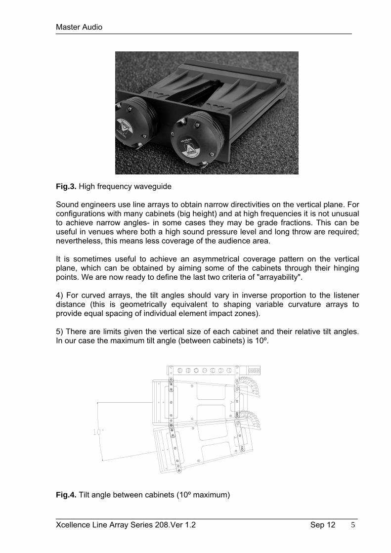
This third condition can be explained through our property waveguide. Thanks to some complex mathematical calculations we have obtained a component which is able to adapt the circular section of the compression driver to a rectangular section, getting on-phase waves at the end of the guide. This flat wavefront is ideal for vertical configurations.
Master Audio
Xcellence Line Array Series 208.Ver 1.2 Sep 12 5
Fig.3. High frequency waveguide
Sound engineers use line arrays to obtain narrow directivities on the vertical plane. For configurations with many cabinets (big height) and at high frequencies it is not unusual to achieve narrow angles- in some cases they may be grade fractions. This can be useful in venues where both a high sound pressure level and long throw are required; nevertheless, this means less coverage of the audience area.
It is sometimes useful to achieve an asymmetrical coverage pattern on the vertical plane, which can be obtained by aiming some of the cabinets through their hinging points. We are now ready to define the last two criteria of "arrayability".
4) For curved arrays, the tilt angles should vary in inverse proportion to the listener distance (this is geometrically equivalent to shaping variable curvature arrays to provide equal spacing of individual element impact zones).
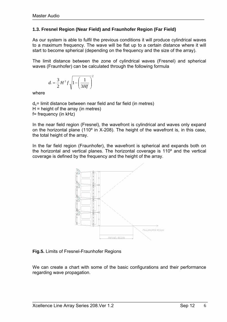
5) There are limits given the vertical size of each cabinet and their relative tilt angles. In our case the maximum tilt angle (between cabinets) is 10º.
Fig.4. Tilt angle between cabinets (10º maximum)
Master Audio
Xcellence Line Array Series 208.Ver 1.2 Sep 12 6
1.3. Fresnel Region (Near Field) and Fraunhofer Region (Far Field)
As our system is able to fulfil the previous conditions it will produce cylindrical waves to a maximum frequency. The wave will be flat up to a certain distance where it will start to become spherical (depending on the frequency and the size of the array).
The limit distance between the zone of cylindrical waves (Fresnel) and spherical waves (Fraunhofer) can be calculated through the following formula
2
2
3
11
2
3
HffHdc
where
dc= limit distance between near field and far field (in metres)H = height of the array (in metres)f= frequency (in kHz)
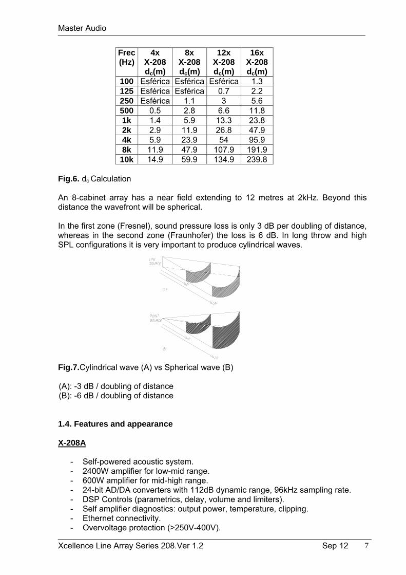
In the near field region (Fresnel), the wavefront is cylindrical and waves only expand on the horizontal plane (110º in X-208). The height of the wavefront is, in this case, the total height of the array.
In the far field region (Fraunhofer), the wavefront is spherical and expands both on the horizontal and vertical planes. The horizontal coverage is 110º and the vertical coverage is defined by the frequency and the height of the array.
Fig.5. Limits of Fresnel-Fraunhofer Regions
We can create a chart with some of the basic configurations and their performance regarding wave propagation.
Master Audio
Xcellence Line Array Series 208.Ver 1.2 Sep 12 7
Frec(Hz)
4xX-208dc(m)
8xX-208
dc(m)
12xX-208dc(m)
16xX-208dc(m)
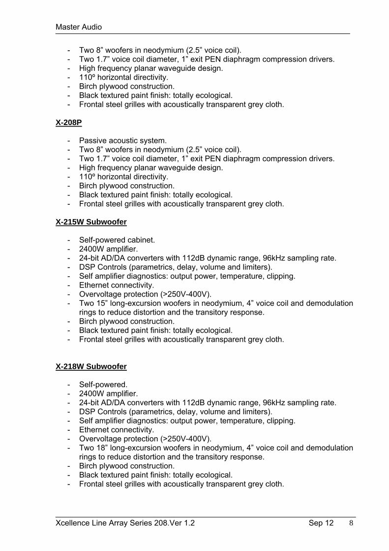
100 Esférica Esférica Esférica 1.3125 Esférica Esférica 0.7 2.2250 Esférica 1.1 3 5.6500 0.5 2.8 6.6 11.81k 1.4 5.9 13.3 23.82k 2.9 11.9 26.8 47.94k 5.9 23.9 54 95.98k 11.9 47.9 107.9 191.9
10k 14.9 59.9 134.9 239.8
Fig.6. dc Calculation
An 8-cabinet array has a near field extending to 12 metres at 2kHz. Beyond this distance the wavefront will be spherical.
In the first zone (Fresnel), sound pressure loss is only 3 dB per doubling of distance, whereas in the second zone (Fraunhofer) the loss is 6 dB. In long throw and high SPL configurations it is very important to produce cylindrical waves.
Fig.7.Cylindrical wave (A) vs Spherical wave (B)
(A): -3 dB / doubling of distance (B): -6 dB / doubling of distance
1.4. Features and appearance
X-208A
- Self-powered acoustic system.- 2400W amplifier for low-mid range.- 600W amplifier for mid-high range.- 24-bit AD/DA converters with 112dB dynamic range, 96kHz sampling rate.- DSP Controls (parametrics, delay, volume and limiters).- Self amplifier diagnostics: output power, temperature, clipping.- Ethernet connectivity.- Overvoltage protection (>250V-400V).
Master Audio
Xcellence Line Array Series 208.Ver 1.2 Sep 12 8
- Two 8” woofers in neodymium (2.5” voice coil).- Two 1.7” voice coil diameter, 1” exit PEN diaphragm compression drivers.- High frequency planar waveguide design.- 110º horizontal directivity.- Birch plywood construction.- Black textured paint finish: totally ecological.- Frontal steel grilles with acoustically transparent grey cloth.
X-208P
- Passive acoustic system.- Two 8” woofers in neodymium (2.5” voice coil).- Two 1.7” voice coil diameter, 1” exit PEN diaphragm compression drivers.- High frequency planar waveguide design.- 110º horizontal directivity.- Birch plywood construction.- Black textured paint finish: totally ecological. - Frontal steel grilles with acoustically transparent grey cloth.
X-215W Subwoofer
- Self-powered cabinet.- 2400W amplifier.- 24-bit AD/DA converters with 112dB dynamic range, 96kHz sampling rate.- DSP Controls (parametrics, delay, volume and limiters).- Self amplifier diagnostics: output power, temperature, clipping.- Ethernet connectivity.- Overvoltage protection (>250V-400V).- Two 15” long-excursion woofers in neodymium, 4” voice coil and demodulation
rings to reduce distortion and the transitory response.- Birch plywood construction.- Black textured paint finish: totally ecological.- Frontal steel grilles with acoustically transparent grey cloth.
X-218W Subwoofer
- Self-powered.- 2400W amplifier.- 24-bit AD/DA converters with 112dB dynamic range, 96kHz sampling rate.- DSP Controls (parametrics, delay, volume and limiters).- Self amplifier diagnostics: output power, temperature, clipping.- Ethernet connectivity.- Overvoltage protection (>250V-400V).- Two 18” long-excursion woofers in neodymium, 4” voice coil and demodulation
rings to reduce distortion and the transitory response. - Birch plywood construction.- Black textured paint finish: totally ecological.- Frontal steel grilles with acoustically transparent grey cloth.
Master Audio
Xcellence Line Array Series 208.Ver 1.2 Sep 12 9
2. X-208A/P FEATURES
The X-208A cabinet includes 2400W bi-amplification for the low-mid range woofers, 600W for the high range compression drivers and digital signal control by DSP. The manufacturer presets make it easy, flexible and user-friendly.
The basic set is composed of three units X-208P (passive) and one unit of X-208A (active). This last model includes all the necessary electronics to feed the X-208P units.
The result is a clean, high quality sound at full power.
2.1. Technical description
The X-208A cabinet comes with DSP control, full range sound delivery thanks to itsdirect radiation transducers and acoustic bass reflex cabinet. As a full range system, its usable bandwidth is 78Hz-18kHz (-10dB).
It has 3000W continuous amplification (2400W + 600W), thermal protection, short circuit protection at the output, maximum power limiters on each channel, and protection against mains overvoltage. The DSP includes some presets which can be selected either accessing the cabinet’s rear control panel or via the computer with Ethernet connection.
The X-208A cabinets are connected using the XLR balanced connector. Mains supply is through PowerCon at 230V.
Both X-208A and X-208P are built in birch plywood which has a high resistance against vibrations and humidity.
High resistance weatherproof bi-component paint. The front face is protected by two1,5 mm thick steel grilles with acoustically transparent grey cloth.
They include in-built black painted stainless steel rigging hardware and handles for an easy and comfortable transport.
2.2. Presets
The X-208A includes some manufacturer presets for different types of application. The DSP system can also store up to 23 customer’s presets, depending on user requirements.
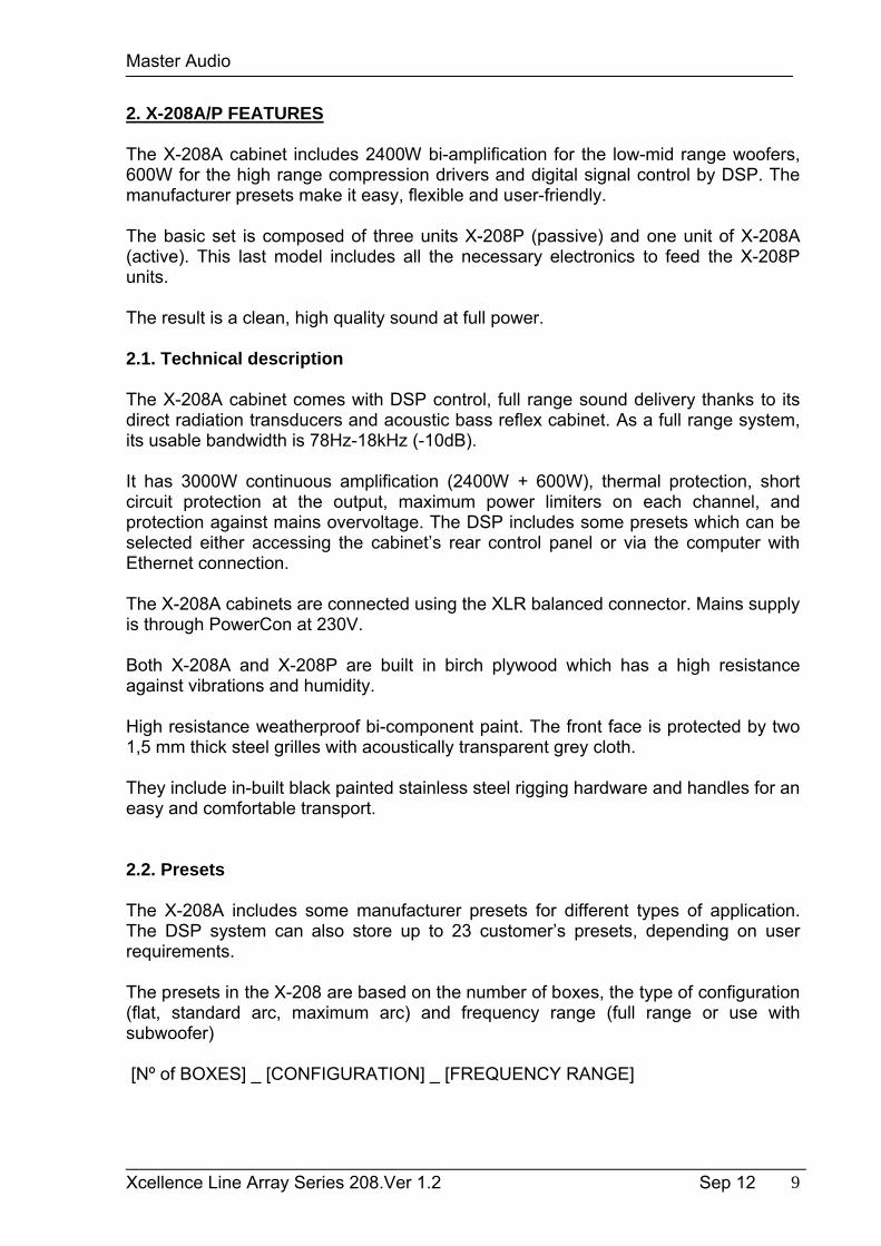
The presets in the X-208 are based on the number of boxes, the type of configuration (flat, standard arc, maximum arc) and frequency range (full range or use with subwoofer)
[Nº of BOXES] _ [CONFIGURATION] _ [FREQUENCY RANGE]
Master Audio
Xcellence Line Array Series 208.Ver 1.2 Sep 12 10
[Nº of BOXES]
2 : 2 boxes4 : 4 boxes – 6 boxes8 : 8 or more boxes
[CONFIGURATION]
FLAT: Flat boxes at 0º (longthrow application)ARC-: Standard curved boxes, i.e. 0º/1º/3º/6º or similar (for mid field application). ARC+: Maximum curved boxes, i.e. 5º or more degrees between cabinets (for nearfield application)
[FREQUENCY RANGE]
FR: Full-range. Frequency response down to 78Hz SW: Frequency response down to 90Hz (for subwoofer use)
Example:
[4FLAT_FR]: 4 boxes / flat configuration / full-range
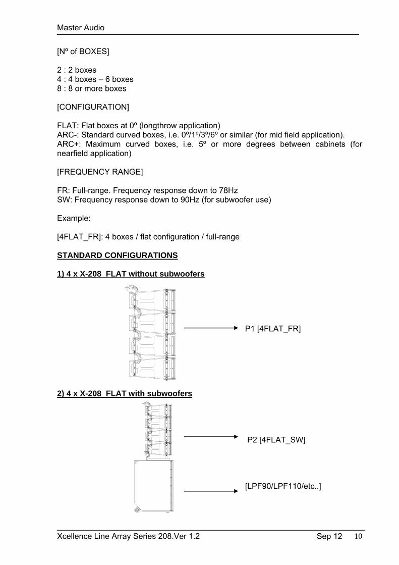
STANDARD CONFIGURATIONS
1) 4 x X-208 FLAT without subwoofers
P1 [4FLAT_FR]
2) 4 x X-208 FLAT with subwoofers
P2 [4FLAT_SW]
[LPF90/LPF110/etc..]
Master Audio
Xcellence Line Array Series 208.Ver 1.2 Sep 12 11
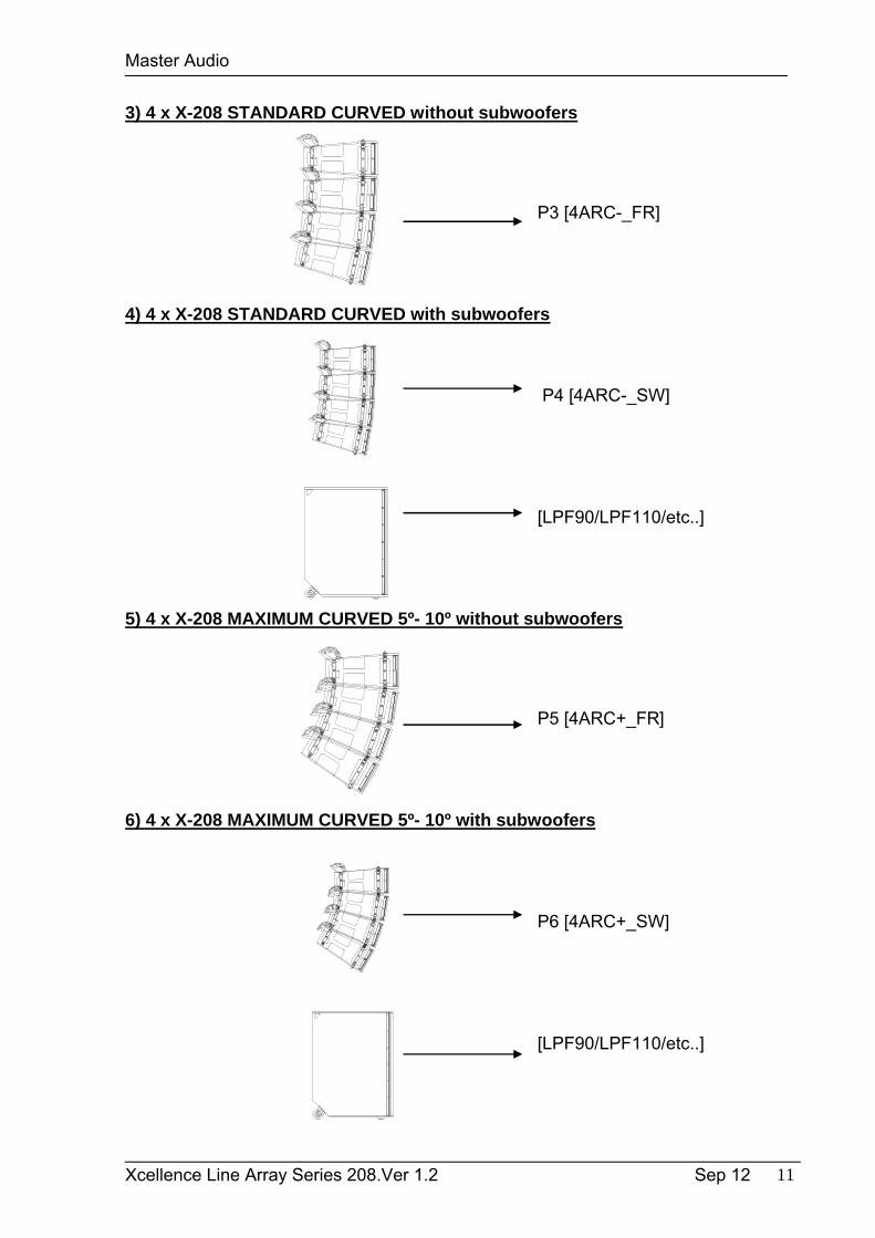
3) 4 x X-208 STANDARD CURVED without subwoofers
P3 [4ARC-_FR]
4) 4 x X-208 STANDARD CURVED with subwoofers
P4 [4ARC-_SW]
[LPF90/LPF110/etc..]
5) 4 x X-208 MAXIMUM CURVED 5º- 10º without subwoofers
P5 [4ARC+_FR]
6) 4 x X-208 MAXIMUM CURVED 5º- 10º with subwoofers
P6 [4ARC+_SW]
[LPF90/LPF110/etc..]
Master Audio
Xcellence Line Array Series 208.Ver 1.2 Sep 12 12
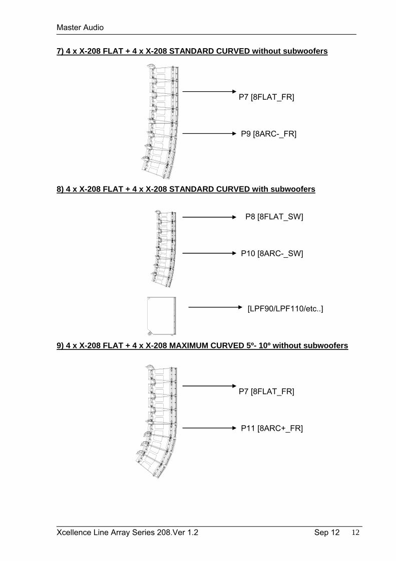
7) 4 x X-208 FLAT + 4 x X-208 STANDARD CURVED without subwoofers
P7 [8FLAT_FR]
P9 [8ARC-_FR]
8) 4 x X-208 FLAT + 4 x X-208 STANDARD CURVED with subwoofers
P8 [8FLAT_SW]
P10 [8ARC-_SW]
[LPF90/LPF110/etc..]
9) 4 x X-208 FLAT + 4 x X-208 MAXIMUM CURVED 5º- 10º without subwoofers
P7 [8FLAT_FR]
P11 [8ARC+_FR]
Master Audio
Xcellence Line Array Series 208.Ver 1.2 Sep 12 13
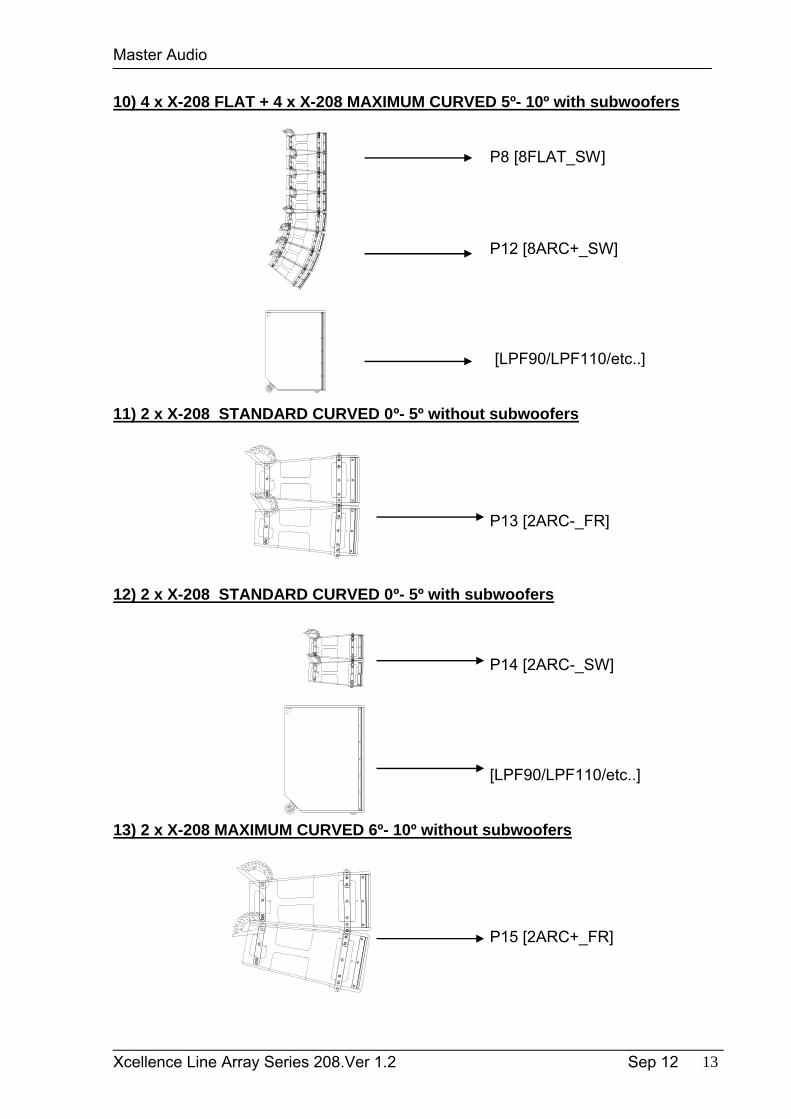
10) 4 x X-208 FLAT + 4 x X-208 MAXIMUM CURVED 5º- 10º with subwoofers
P8 [8FLAT_SW]
P12 [8ARC+_SW]
[LPF90/LPF110/etc..]
11) 2 x X-208 STANDARD CURVED 0º- 5º without subwoofers
P13 [2ARC-_FR]
12) 2 x X-208 STANDARD CURVED 0º- 5º with subwoofers
P14 [2ARC-_SW]
[LPF90/LPF110/etc..]
13) 2 x X-208 MAXIMUM CURVED 6º- 10º without subwoofers
P15 [2ARC+_FR]
Master Audio
Xcellence Line Array Series 208.Ver 1.2 Sep 12 14
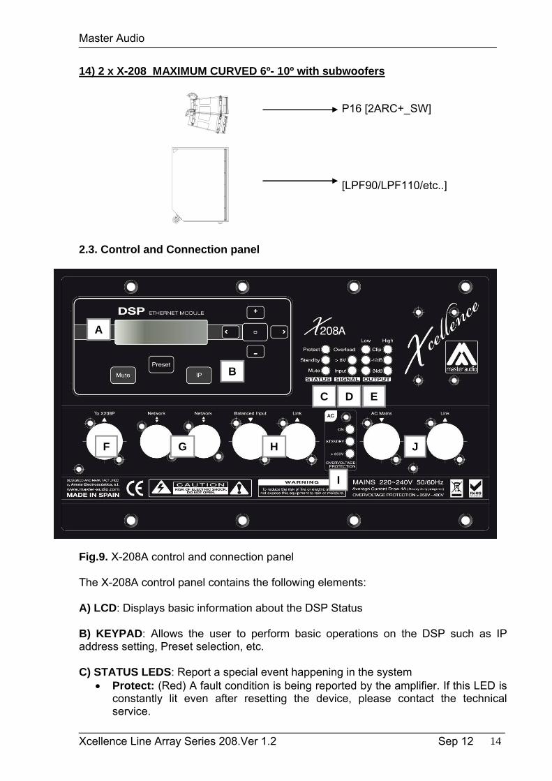
14) 2 x X-208 MAXIMUM CURVED 6º- 10º with subwoofers
P16 [2ARC+_SW]
[LPF90/LPF110/etc..]
2.3. Control and Connection panel
Fig.9. X-208A control and connection panel
The X-208A control panel contains the following elements:
A) LCD: Displays basic information about the DSP Status
B) KEYPAD: Allows the user to perform basic operations on the DSP such as IP address setting, Preset selection, etc.
C) STATUS LEDS: Report a special event happening in the system Protect: (Red) A fault condition is being reported by the amplifier. If this LED is
constantly lit even after resetting the device, please contact the technical service.
A
B
C D E
F G H
I
J
Master Audio
Xcellence Line Array Series 208.Ver 1.2 Sep 12 15
Standby: (Orange) This led is lit when the equipment is set in Low Power Consumption mode. This mode can only be set through the PC connection.
Mute: (Orange) The system is muted (amplifiers are disabled). The system can be muted from the PC remote control or from the keypad.
IMPORTANT: When the amplifier is in MUTE, the PROTECT LED will be also lit to show that the amplifier is disabled. Also when the system is waking up from the STANDBY mode, the PROTECT led will be lit for a few seconds. Under these circumstances the PROTECT LED is reporting that the amplifier is disabled, but not a fault condition.
D) SIGNAL INPUT LEDS: Monitor the signal arriving at the module input. Input: Signal is present at the input. Nominal input level is +8dBu (2Vrms). >8 Overload: The input signal exceeds +14dBu (4Vrms), so it will be
compressed. Avoid the continuous lighting of this led in order to preserve the dynamic range of the audio signal.
E) OUPUT LEDS: Show the amplifier output level, both for Low and High channels. -24dB: The amplifier is delivering output power at -24dB of its maximum power -12dB: The amplifier is delivering output power at -12dB of its maximum power Clip: The amplifier is delivering its maximum output power
The connection panel has the following parts:
F) SLAVE OUTPUT FOR X-208P4P-Speakon connector used to feed up to three slaves X-208P Line Array Element. In order to assure proper operation always follow these instructions:
Link up to THREE units of X-208P with each X-208A. Do not connect a loudspeaker different than X-208P to this output. Do not change or manipulate this connector. Always follow the polarity if the 4-pole connector
o 1+/1-: LF+/LF-o 2+/2-: HF+/HF-
Misusing the slave output for X-208P may lead to serious damage for all involved equipment, and will not be covered by the Warranty.
G) NETWORK: Computer connection through Ethernet protocol. Two 8-pin RJ45 / EtherCon® compatible connectors with an internal switch allow the connection of several units in daisy-chain. Please refer to Master Audio DSPStudio Quick Installation Guide for more information on the remote connection.
H) BALANCED INPUT/LINK: XLR-3 Female balanced signal connector for signal input.XLR-3 Male connector for parallel connection of various cabinets with the same input signal.IMPORTANT: Please always use balanced microphone cable with the following pin assignment:
1= Shield (Ground) 2= Live (+) 3= Return (-)
Master Audio
Xcellence Line Array Series 208.Ver 1.2 Sep 12 16
I) AC INPUT/OVERVOLTAGE PROTECTION: These leds show the status of the AC mains supply.
ON: (Blue) When lit, the equipment is ON and the AC input level is within the permitted range (200 to 250 VAC).
STANDBY: (Orange) This led is lit when the equipment is sensing the AC voltage at the input. At power-up this led will lit for a second while the systems checks for the input voltage.
>250V OVERVOLTAGE PROTECTION: (Red) When activated, the AC voltage is permanently out of the permitted range of the equipment, so it will remain under protection until this condition is solved. Revise your connections and mains power installation and consider that other equipment connected to this line may have been damaged.
J) AC MAINS INPUT/LINK: Mains supply connection via PowerCon. Blue connector for AC in. Grey connector to feed other units in parallel. Linking up to 4 units of X-208A is
possible, provided that a quality cable of a minimum section of 3x2.5mm2 is used. Connecting more than 4 units in parallel may lead to a voltage drop in the cable that will reduce the equipment performance.
Always use mains power cable supplied by manufacturer.Never connect the Xcellence Line Array cabinets to an unearthed mains supply or by using an unearthed mains cable.
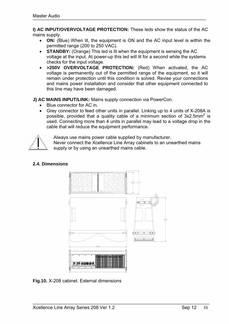
2.4. Dimensions
Fig.10. X-208 cabinet. External dimensions
Master Audio
Xcellence Line Array Series 208.Ver 1.2 Sep 12 17
3. X-215W SUBWOOFER
The X-215W cabinet is ideal for bass reinforcement. It includes 2400W amplification for the woofers and digital signal control by DSP. The manufacturer presets (LPF90+3, LPF90+6, LPF100+3, LPF100+6, LPF110+3, LPF110+6, LPF120+3, LPF120+6, CARDIOID) make it easy, flexible and user-friendly.
The 15” neodymium woofers used, thanks to their exclusive magnetic design, combine excellent bass frequency response, high performance and low distortion. These features are mainly due to the presence of demodulation rings which drastically reduce the inter-modulation and third order distortion and considerably improve the transitory response. There is excellent heat dissipation due to the external positioning of the magnet set. Without any doubt one of the finest bass transducers currently available.The result is a clean, high quality sound.
3.1. Technical description
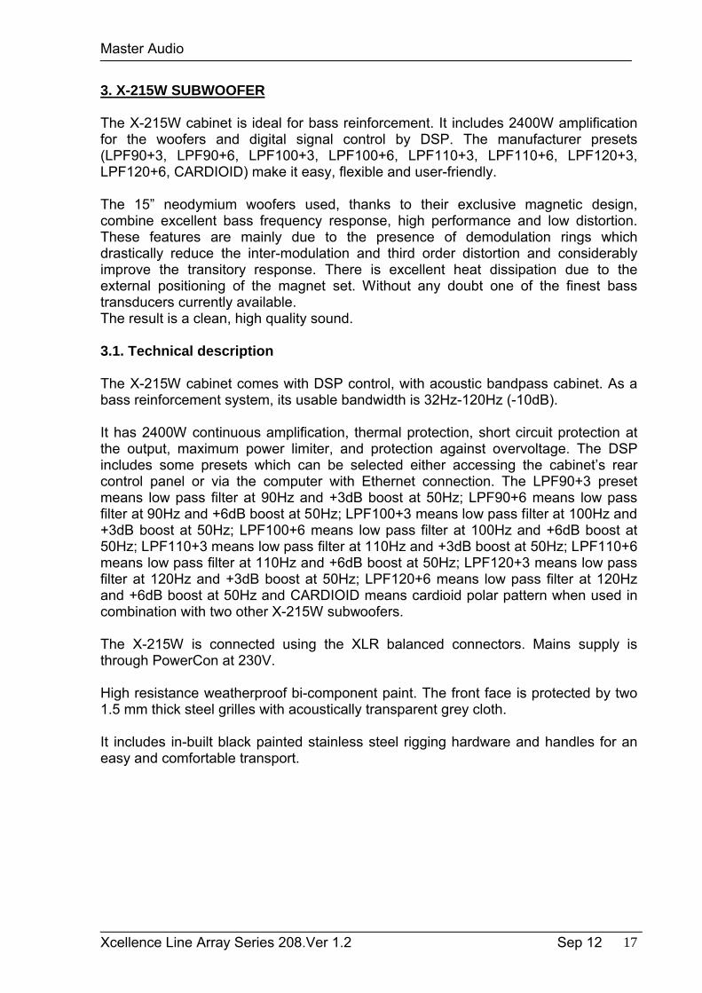
The X-215W cabinet comes with DSP control, with acoustic bandpass cabinet. As a bass reinforcement system, its usable bandwidth is 32Hz-120Hz (-10dB).
It has 2400W continuous amplification, thermal protection, short circuit protection at the output, maximum power limiter, and protection against overvoltage. The DSP includes some presets which can be selected either accessing the cabinet’s rear control panel or via the computer with Ethernet connection. The LPF90+3 preset means low pass filter at 90Hz and +3dB boost at 50Hz; LPF90+6 means low pass filter at 90Hz and +6dB boost at 50Hz; LPF100+3 means low pass filter at 100Hz and +3dB boost at 50Hz; LPF100+6 means low pass filter at 100Hz and +6dB boost at 50Hz; LPF110+3 means low pass filter at 110Hz and +3dB boost at 50Hz; LPF110+6 means low pass filter at 110Hz and +6dB boost at 50Hz; LPF120+3 means low pass filter at 120Hz and +3dB boost at 50Hz; LPF120+6 means low pass filter at 120Hz and +6dB boost at 50Hz and CARDIOID means cardioid polar pattern when used in combination with two other X-215W subwoofers.
The X-215W is connected using the XLR balanced connectors. Mains supply is through PowerCon at 230V.
High resistance weatherproof bi-component paint. The front face is protected by two 1.5 mm thick steel grilles with acoustically transparent grey cloth.
It includes in-built black painted stainless steel rigging hardware and handles for an easy and comfortable transport.
Master Audio
Xcellence Line Array Series 208.Ver 1.2 Sep 12 18
Fig.11. X-215W cabinet. External dimensions
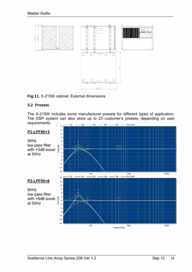
3.2. Presets
The X-215W includes some manufacturer presets for different types of application. The DSP system can also store up to 23 customer’s presets, depending on user requirements.
P1-LPF90+3
90Hz low pass filterwith +3dB boostat 50Hz
P2-LPF90+6
90Hzlow pass filterwith +6dB boostat 50Hz
Master Audio
Xcellence Line Array Series 208.Ver 1.2 Sep 12 19
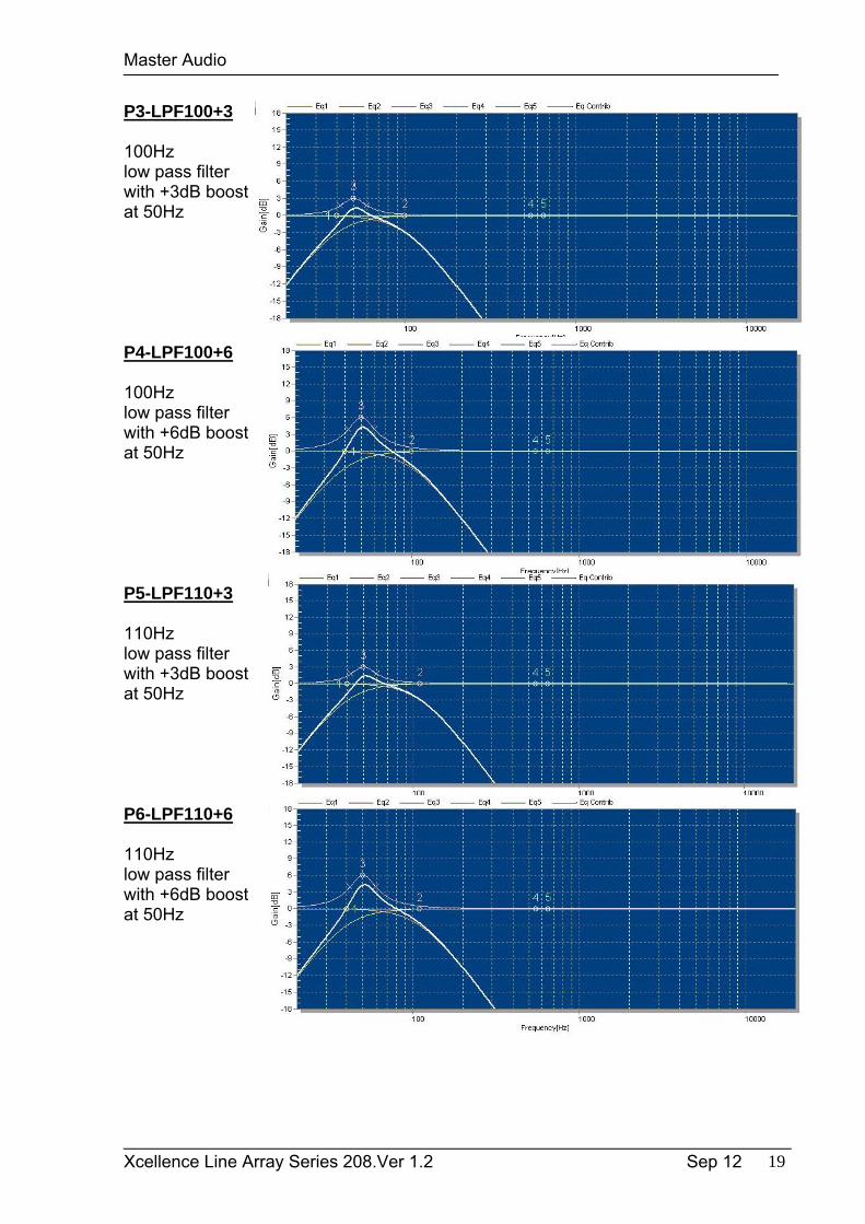
P3-LPF100+3
100Hzlow pass filterwith +3dB boostat 50Hz
P4-LPF100+6
100Hz low pass filter with +6dB boostat 50Hz
P5-LPF110+3
110Hzlow pass filterwith +3dB boostat 50Hz
P6-LPF110+6
110Hz low pass filter with +6dB boostat 50Hz
Master Audio
Xcellence Line Array Series 208.Ver 1.2 Sep 12 20
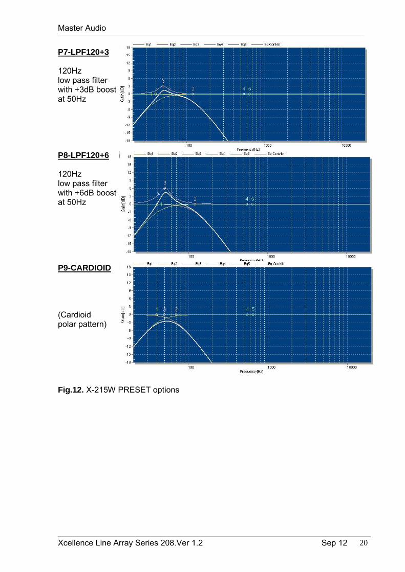
P7-LPF120+3
120Hzlow pass filterwith +3dB boostat 50Hz
P8-LPF120+6
120Hz low pass filter with +6dB boostat 50Hz
P9-CARDIOID
(Cardioidpolar pattern)
Fig.12. X-215W PRESET options
Master Audio
Xcellence Line Array Series 208.Ver 1.2 Sep 12 21
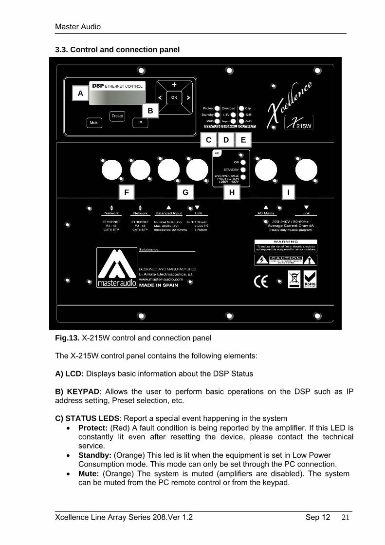
3.3. Control and connection panel
Fig.13. X-215W control and connection panel
The X-215W control panel contains the following elements:
A) LCD: Displays basic information about the DSP Status
B) KEYPAD: Allows the user to perform basic operations on the DSP such as IP address setting, Preset selection, etc.
C) STATUS LEDS: Report a special event happening in the system Protect: (Red) A fault condition is being reported by the amplifier. If this LED is
constantly lit even after resetting the device, please contact the technical service.
Standby: (Orange) This led is lit when the equipment is set in Low Power Consumption mode. This mode can only be set through the PC connection.
Mute: (Orange) The system is muted (amplifiers are disabled). The system can be muted from the PC remote control or from the keypad.
A
B
C D E
F G H I

Master Audio
Xcellence Line Array Series 208.Ver 1.2 Sep 12 22
IMPORTANT: When the amplifier is in MUTE, the PROTECT LED will be also lit to show that the amplifier is disabled. Also when the system is waking up from the STANDBY mode, the PROTECT led will be lit for a few seconds. Under these circumstances the PROTECT LED is reporting that the amplifier is disabled, but not a fault condition.
D) SIGNAL INPUT LEDS: Monitor the signal arriving at the module input. Input: Signal is present at the input. Nominal input level is +8dBu (2Vrms). OVLD: The input signal exceeds +14dBu (4Vrms), so it will be compressed.
Avoid the continuous lighting of this led in order to preserve the dynamic range of the audio signal.
E) OUPUT LEDS: Show the amplifier output level -24dB: The amplifier is delivering output power at -24dB of its maximum power -12dB: The amplifier is delivering output power at -12dB of its maximum power Clip: The amplifier is delivering its maximum output power
The connection panel has the following parts:
F) NETWORK: Computer connection through Ethernet protocol. Two 8-pin RJ45 / EtherCon® compatible connectors with an internal switch allow the connection of several units in daisy-chain. Please refer to Master Audio DSPStudio Quick Installation Guide for more information on the remote connection.
G) BALANCED INPUT/LINK: XLR-3 Female balanced signal connector for signal input.XLR-3 Male connector for parallel connection of various cabinets with the same input signal.IMPORTANT: Please always use balanced microphone cable with the following pin assignment:
1= Shield (Ground) 2= Live (+) 3= Return (-)
H) AC INPUT/OVERVOLTAGE PROTECTION: These leds show the status of the AC mains supply.
ON: (Blue) When lit, the equipment is ON and the AC input level is within the permitted range (200 to 250 VAC).
STANDBY: (Orange) This led is lit when the equipment is sensing the AC voltage at the input. At power-up this led will lit for a second while the systems checks for the input voltage.
OVERVOLTAGE PROTECTION: (Red) When activated, the AC voltage is permanently out of the permitted range of the equipment (>250VAC), so it will remain under protection until this condition is solved. Revise your connections and mains power installation and consider that other equipment connected to this line may have been damaged.
I) AC MAINS INPUT/LINK: Mains supply connection via PowerCon. Blue connector for AC in. Grey connector to feed other units in parallel. Linking up to 2 units of X-215W is
possible, provided that a quality cable of a minimum section of 3x2,5 mm2 is used. Connecting more than 2 units in parallel may lead to a voltage drop in the cable that will reduce the equipment performance.
Master Audio
Xcellence Line Array Series 208.Ver 1.2 Sep 12 23
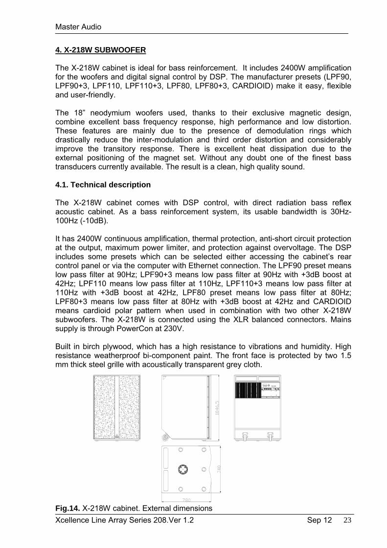
4. X-218W SUBWOOFER
The X-218W cabinet is ideal for bass reinforcement. It includes 2400W amplification for the woofers and digital signal control by DSP. The manufacturer presets (LPF90, LPF90+3, LPF110, LPF110+3, LPF80, LPF80+3, CARDIOID) make it easy, flexible and user-friendly.
The 18” neodymium woofers used, thanks to their exclusive magnetic design, combine excellent bass frequency response, high performance and low distortion. These features are mainly due to the presence of demodulation rings which drastically reduce the inter-modulation and third order distortion and considerably improve the transitory response. There is excellent heat dissipation due to the external positioning of the magnet set. Without any doubt one of the finest bass transducers currently available. The result is a clean, high quality sound.
4.1. Technical description
The X-218W cabinet comes with DSP control, with direct radiation bass reflex acoustic cabinet. As a bass reinforcement system, its usable bandwidth is 30Hz-100Hz (-10dB).
It has 2400W continuous amplification, thermal protection, anti-short circuit protection at the output, maximum power limiter, and protection against overvoltage. The DSP includes some presets which can be selected either accessing the cabinet’s rear control panel or via the computer with Ethernet connection. The LPF90 preset means low pass filter at 90Hz; LPF90+3 means low pass filter at 90Hz with +3dB boost at 42Hz; LPF110 means low pass filter at 110Hz, LPF110+3 means low pass filter at 110Hz with +3dB boost at 42Hz, LPF80 preset means low pass filter at 80Hz; LPF80+3 means low pass filter at 80Hz with +3dB boost at 42Hz and CARDIOID means cardioid polar pattern when used in combination with two other X-218W subwoofers. The X-218W is connected using the XLR balanced connectors. Mains supply is through PowerCon at 230V.
Built in birch plywood, which has a high resistance to vibrations and humidity. High resistance weatherproof bi-component paint. The front face is protected by two 1.5 mm thick steel grille with acoustically transparent grey cloth.
Fig.14. X-218W cabinet. External dimensions
Master Audio
Xcellence Line Array Series 208.Ver 1.2 Sep 12 24
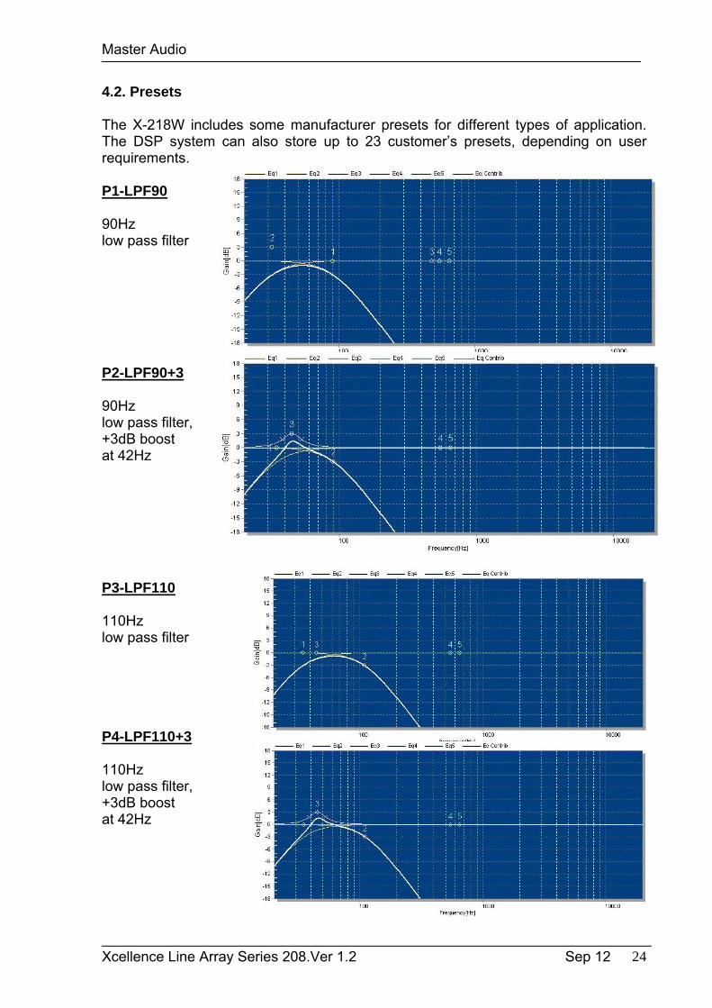
4.2. Presets
The X-218W includes some manufacturer presets for different types of application. The DSP system can also store up to 23 customer’s presets, depending on user requirements.
P1-LPF90
90Hzlow pass filter
P2-LPF90+3
90Hz low pass filter,+3dB boostat 42Hz
P3-LPF110
110Hz low pass filter
P4-LPF110+3
110Hz low pass filter, +3dB boostat 42Hz
Master Audio
Xcellence Line Array Series 208.Ver 1.2 Sep 12 25
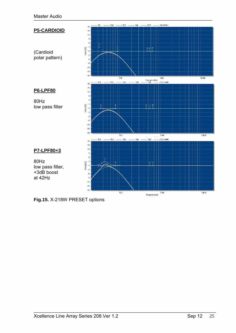
P5-CARDIOID
(Cardioidpolar pattern)
P6-LPF80
80Hz low pass filter
P7-LPF80+3
80Hz low pass filter, +3dB boostat 42Hz
Fig.15. X-218W PRESET options
Master Audio
Xcellence Line Array Series 208.Ver 1.2 Sep 12 26
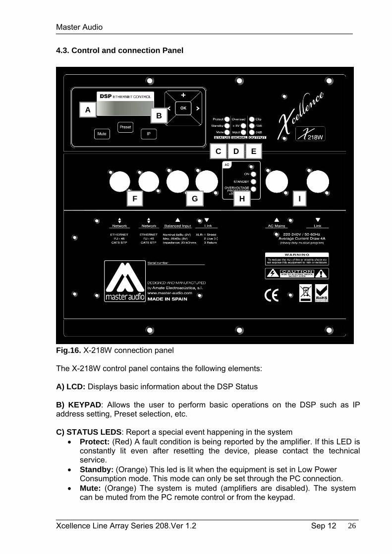
4.3. Control and connection Panel
Fig.16. X-218W connection panel
The X-218W control panel contains the following elements:
A) LCD: Displays basic information about the DSP Status
B) KEYPAD: Allows the user to perform basic operations on the DSP such as IP address setting, Preset selection, etc.
C) STATUS LEDS: Report a special event happening in the system Protect: (Red) A fault condition is being reported by the amplifier. If this LED is
constantly lit even after resetting the device, please contact the technical service.
Standby: (Orange) This led is lit when the equipment is set in Low Power Consumption mode. This mode can only be set through the PC connection.
Mute: (Orange) The system is muted (amplifiers are disabled). The system can be muted from the PC remote control or from the keypad.
AB
C D E
F G H I
Master Audio
Xcellence Line Array Series 208.Ver 1.2 Sep 12 27
IMPORTANT: When the amplifier is in MUTE, the PROTECT LED will be also lit to show that the amplifier is disabled. Also when the system is waking up from the STANDBY mode, the PROTECT led will be lit for a few seconds. Under these circumstances the PROTECT LED is reporting that the amplifier is disabled, but not a fault condition.
D) SIGNAL INPUT LEDS: Monitor the signal arriving at the module input. Input: Signal is present at the input. Nominal input level is +8dBu (2Vrms). OVLD: The input signal exceeds +14dBu (4Vrms), so it will be compressed.
Avoid the continuous lighting of this led in order to preserve the dynamic range of the audio signal.
E) OUPUT LEDS: Show the amplifier output level -24dB: The amplifier is delivering output power at -24dB of its maximum power -12dB: The amplifier is delivering output power at -12dB of its maximum power Clip: The amplifier is delivering its maximum output power
The connection panel has the following parts:
F) NETWORK: Computer connection through Ethernet protocol. Two 8-pin RJ45 / EtherCon® compatible connectors with an internal switch allow the connection of several units in daisy-chain. Please refer to Master Audio DSPStudio Quick Installation Guide for more information on the remote connection.
G) BALANCED INPUT/LINK: XLR-3 Female balanced signal connector for signal input.XLR-3 Male connector for parallel connection of various cabinets with the same input signal.IMPORTANT: Please always use balanced microphone cable with the following pin assignment:
1= Shield (Ground) 2= Live (+) 3= Return (-)
H) AC INPUT/OVERVOLTAGE PROTECTION: These leds show the status of the AC mains supply.
ON: (Blue) When lit, the equipment is ON and the AC input level is within the permitted range (200 to 250 VAC).
STANDBY: (Orange) This led is lit when the equipment is sensing the AC voltage at the input. At power-up this led will lit for a second while the systems checks for the input voltage.
OVERVOLTAGE PROTECTION: (Red) When activated, the AC voltage is permanently out of the permitted range of the equipment (>250VAC), so it will remain under protection until this condition is solved. Revise your connections and mains power installation and consider that other equipment connected to this line may have been damaged.
I) AC MAINS INPUT/LINK: Mains supply connection via PowerCon. Blue connector for AC in. Grey connector to feed other units in parallel. Linking up to 2 units of X-218W is
possible, provided that a quality cable of a minimum section of 3x2,5mm2 is used. Connecting more than 2 units in parallel may lead to a voltage drop in the cable that will reduce the equipment performance.
Master Audio
Xcellence Line Array Series 208.Ver 1.2 Sep 12 28
5. CARDIOID SUBWOOFERS
Both X-215W and X-218W enable the combination of three or multiple of three subwoofer cabinets in an array to provide exceptional directivity at low frequencies.
High directivity at low frequencies has two main effects on the sound field: firstly, the low frequency level behind the subwoofer cabinets is greatly reduced; secondly, in closed venues the diffuse sound field at low frequencies is reduced so the low frequency reproduction is much more precise.
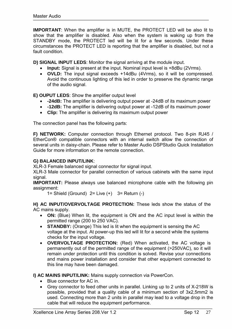
The typical operating range of a traditional subwoofer tends to be like a monopole, i.e. tends to radiate with the same energy in all directions. This behaviour implies that the control of radiation at low frequencies is very difficult because the wavelengths are very large compared to the size of the source (8.5 m at 40Hz).
Fig.17. Traditional polar pattern of a subwoofer at 40Hz
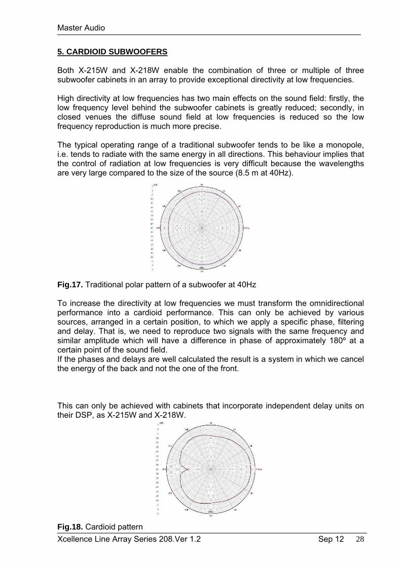
To increase the directivity at low frequencies we must transform the omnidirectional performance into a cardioid performance. This can only be achieved by various sources, arranged in a certain position, to which we apply a specific phase, filteringand delay. That is, we need to reproduce two signals with the same frequency and similar amplitude which will have a difference in phase of approximately 180º at a certain point of the sound field.If the phases and delays are well calculated the result is a system in which we cancelthe energy of the back and not the one of the front.
This can only be achieved with cabinets that incorporate independent delay units on their DSP, as X-215W and X-218W.
Fig.18. Cardioid pattern
Master Audio
Xcellence Line Array Series 208.Ver 1.2 Sep 12 29
5.1. The CARDIOID preset
X-215W and X-218W can generate an uncompromised cardioid behaviour, which means that there is no need for special cabinets, enabling the use of the system’s full efficiency with just “one finger”.
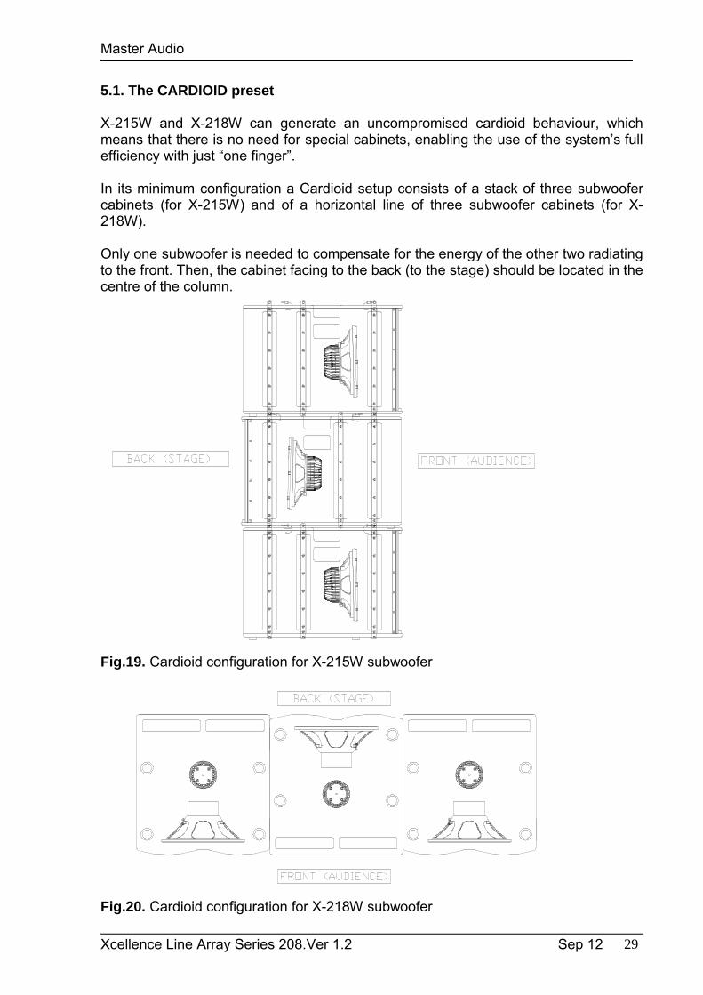
In its minimum configuration a Cardioid setup consists of a stack of three subwoofer cabinets (for X-215W) and of a horizontal line of three subwoofer cabinets (for X-218W).
Only one subwoofer is needed to compensate for the energy of the other two radiating to the front. Then, the cabinet facing to the back (to the stage) should be located in the centre of the column.
Fig.19. Cardioid configuration for X-215W subwoofer
Fig.20. Cardioid configuration for X-218W subwoofer
Master Audio
Xcellence Line Array Series 208.Ver 1.2 Sep 12 30
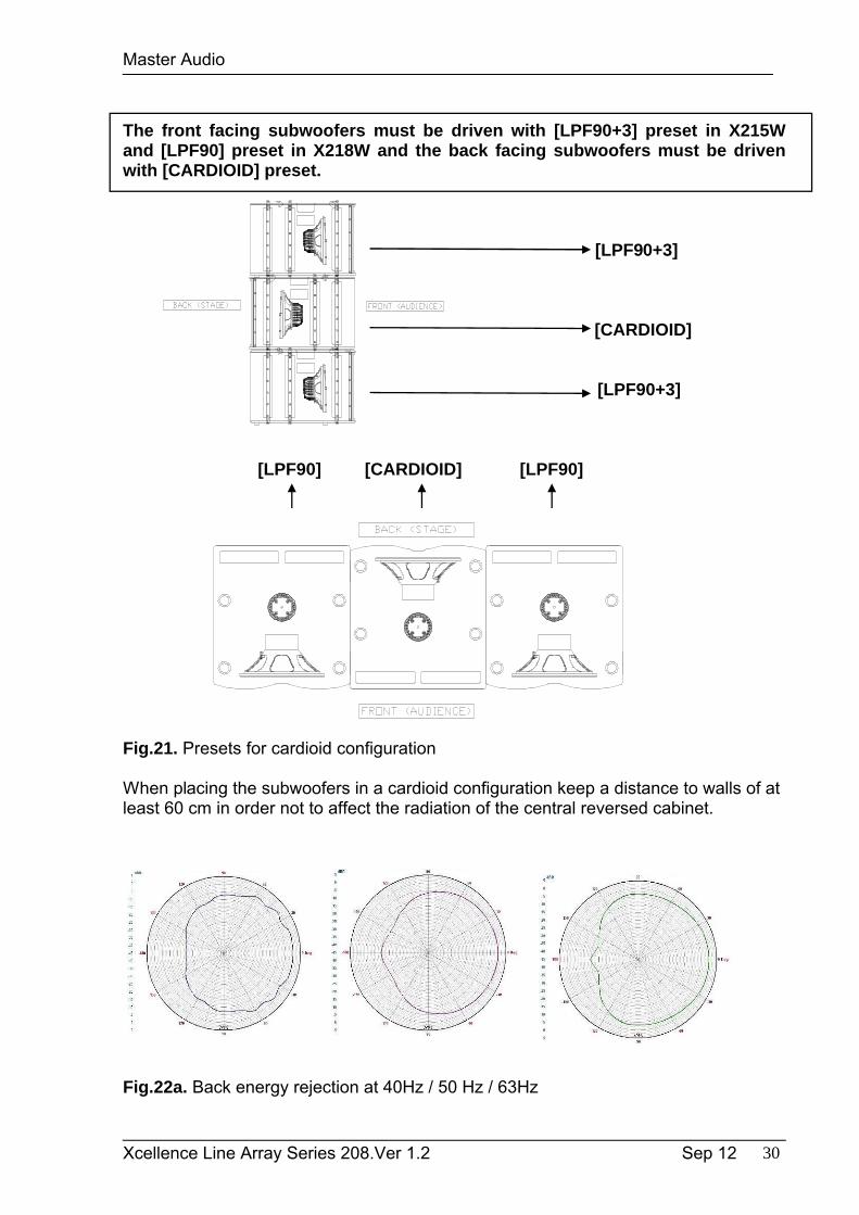
The front facing subwoofers must be driven with [LPF90+3] preset in X215Wand [LPF90] preset in X218W and the back facing subwoofers must be driven with [CARDIOID] preset.
[LPF90+3]
[CARDIOID]
[LPF90+3]
[LPF90] [CARDIOID] [LPF90]
Fig.21. Presets for cardioid configuration
When placing the subwoofers in a cardioid configuration keep a distance to walls of at least 60 cm in order not to affect the radiation of the central reversed cabinet.
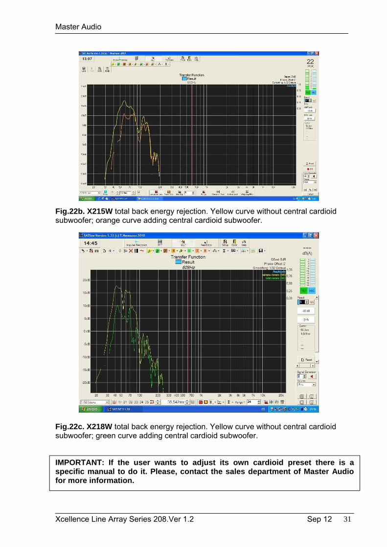
Fig.22a. Back energy rejection at 40Hz / 50 Hz / 63Hz
Master Audio
Xcellence Line Array Series 208.Ver 1.2 Sep 12 31
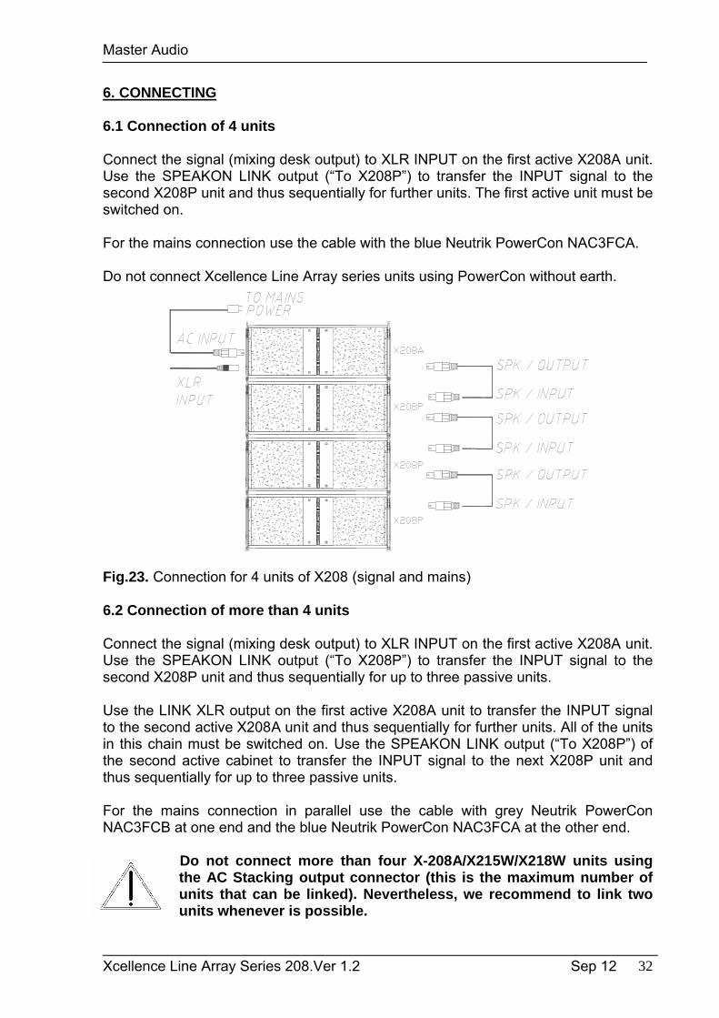
Fig.22b. X215W total back energy rejection. Yellow curve without central cardioid subwoofer; orange curve adding central cardioid subwoofer.
Fig.22c. X218W total back energy rejection. Yellow curve without central cardioid subwoofer; green curve adding central cardioid subwoofer.
IMPORTANT: If the user wants to adjust its own cardioid preset there is a specific manual to do it. Please, contact the sales department of Master Audio for more information.
Master Audio
Xcellence Line Array Series 208.Ver 1.2 Sep 12 32
6. CONNECTING
6.1 Connection of 4 units
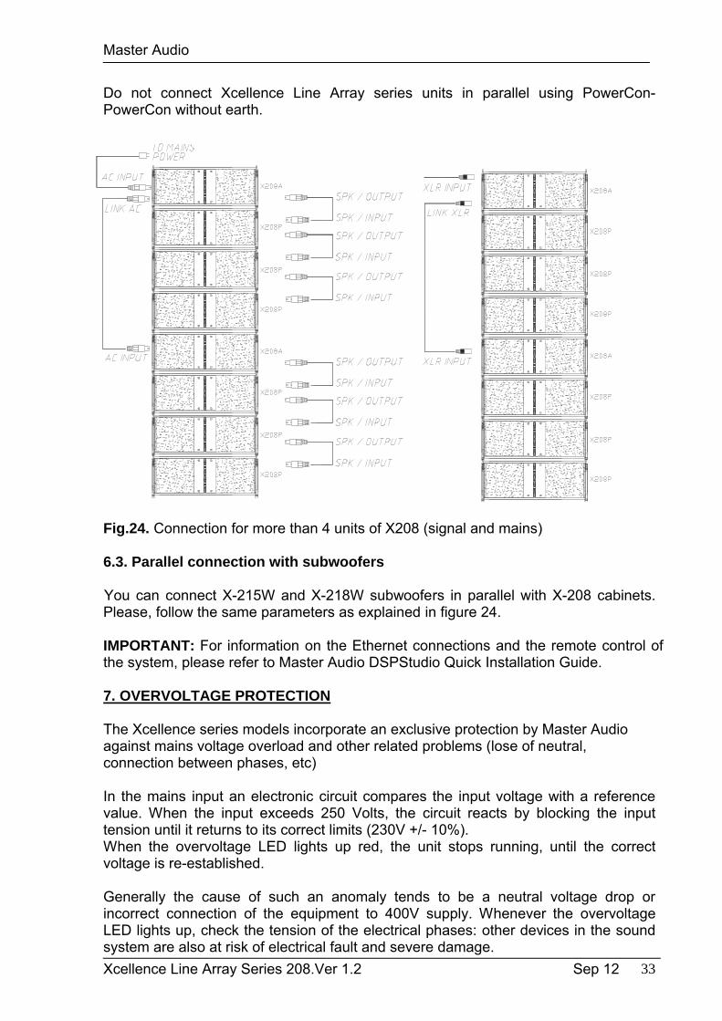
Connect the signal (mixing desk output) to XLR INPUT on the first active X208A unit. Use the SPEAKON LINK output (“To X208P”) to transfer the INPUT signal to the second X208P unit and thus sequentially for further units. The first active unit must be switched on.
For the mains connection use the cable with the blue Neutrik PowerCon NAC3FCA.
Do not connect Xcellence Line Array series units using PowerCon without earth.
Fig.23. Connection for 4 units of X208 (signal and mains)
6.2 Connection of more than 4 units
Connect the signal (mixing desk output) to XLR INPUT on the first active X208A unit.Use the SPEAKON LINK output (“To X208P”) to transfer the INPUT signal to the second X208P unit and thus sequentially for up to three passive units.
Use the LINK XLR output on the first active X208A unit to transfer the INPUT signal to the second active X208A unit and thus sequentially for further units. All of the units in this chain must be switched on. Use the SPEAKON LINK output (“To X208P”) of the second active cabinet to transfer the INPUT signal to the next X208P unit and thus sequentially for up to three passive units.
For the mains connection in parallel use the cable with grey Neutrik PowerCon NAC3FCB at one end and the blue Neutrik PowerCon NAC3FCA at the other end.
Do not connect more than four X-208A/X215W/X218W units using the AC Stacking output connector (this is the maximum number of units that can be linked). Nevertheless, we recommend to link two units whenever is possible.
Master Audio
Xcellence Line Array Series 208.Ver 1.2 Sep 12 33
Do not connect Xcellence Line Array series units in parallel using PowerCon-PowerCon without earth.
Fig.23. Parallel connection for the Xcellence Line Array series (signal and mains)
Fig.24. Connection for more than 4 units of X208 (signal and mains)
6.3. Parallel connection with subwoofers
You can connect X-215W and X-218W subwoofers in parallel with X-208 cabinets. Please, follow the same parameters as explained in figure 24.
IMPORTANT: For information on the Ethernet connections and the remote control of the system, please refer to Master Audio DSPStudio Quick Installation Guide.
7. OVERVOLTAGE PROTECTION
The Xcellence series models incorporate an exclusive protection by Master Audio against mains voltage overload and other related problems (lose of neutral, connection between phases, etc)
In the mains input an electronic circuit compares the input voltage with a reference value. When the input exceeds 250 Volts, the circuit reacts by blocking the input tension until it returns to its correct limits (230V +/- 10%).When the overvoltage LED lights up red, the unit stops running, until the correct voltage is re-established.
Generally the cause of such an anomaly tends to be a neutral voltage drop or incorrect connection of the equipment to 400V supply. Whenever the overvoltage LED lights up, check the tension of the electrical phases: other devices in the sound system are also at risk of electrical fault and severe damage.
Master Audio
Xcellence Line Array Series 208.Ver 1.2 Sep 12 34
8. MOUNTING AND INSTALLATION
Flying an Xcellence Line Array system is easy, fast and secure. To perform any operations related to flying the system, read the present document, and act on the warnings and advice given.
Only experienced installers with adequate knowledge of the system and local safety regulations should fly speaker cabinets.
It is the user's responsibility to ensure that the systems to be flown and the flying accessories (such as chains, eyebolts, lock pins...) comply with state and local regulations. They should be regularly inspected and replaced if in doubt.
When flying enclosures from ceiling support structures, extreme care should be taken to assure the load bearing capabilities of them. Do not fly systems from unsafe structures.
All flying accessories that are not supplied by Master Audio are the user's responsibility. Use at your own risk.
Remember that no risks should be taken with regards to public safety.
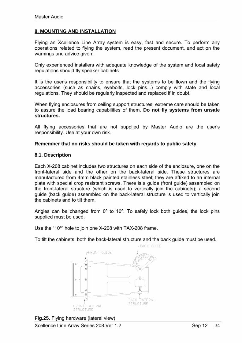
8.1. Description
Each X-208 cabinet includes two structures on each side of the enclosure, one on the front-lateral side and the other on the back-lateral side. These structures are manufactured from 4mm black painted stainless steel; they are affixed to an internal plate with special crop resistant screws. There is a guide (front guide) assembled on the front-lateral structure (which is used to vertically join the cabinets); a second guide (back guide) assembled on the back-lateral structure is used to vertically join the cabinets and to tilt them.
Angles can be changed from 0º to 10º. To safely lock both guides, the lock pins supplied must be used.
Use the “10º” hole to join one X-208 with TAX-208 frame.
To tilt the cabinets, both the back-lateral structure and the back guide must be used.
Fig.25. Flying hardware (lateral view)
Master Audio
Xcellence Line Array Series 208.Ver 1.2 Sep 12 35
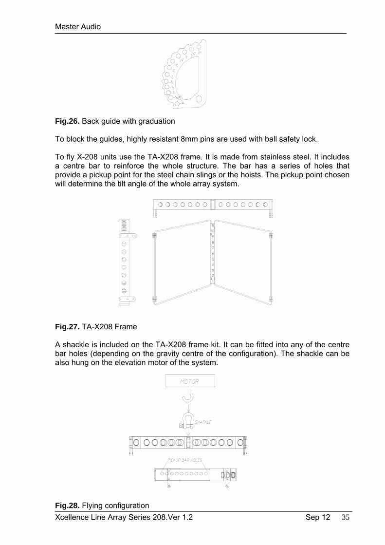
Fig.26. Back guide with graduation
To block the guides, highly resistant 8mm pins are used with ball safety lock.
To fly X-208 units use the TA-X208 frame. It is made from stainless steel. It includes a centre bar to reinforce the whole structure. The bar has a series of holes that provide a pickup point for the steel chain slings or the hoists. The pickup point chosen will determine the tilt angle of the whole array system.
Fig.27. TA-X208 Frame
A shackle is included on the TA-X208 frame kit. It can be fitted into any of the centre bar holes (depending on the gravity centre of the configuration). The shackle can be also hung on the elevation motor of the system.
Fig.28. Flying configuration
Master Audio
Xcellence Line Array Series 208.Ver 1.2 Sep 12 36
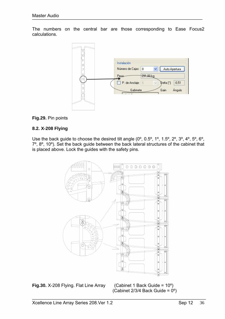
The numbers on the central bar are those corresponding to Ease Focus2 calculations.
Fig.29. Pin points
8.2. X-208 Flying
Use the back guide to choose the desired tilt angle (0º, 0.5º, 1º, 1.5º, 2º, 3º, 4º, 5º, 6º, 7º, 8º, 10º). Set the back guide between the back lateral structures of the cabinet that is placed above. Lock the guides with the safety pins.
Fig.30. X-208 Flying. Flat Line Array (Cabinet 1 Back Guide = 10º)(Cabinet 2/3/4 Back Guide = 0º)
Master Audio
Xcellence Line Array Series 208.Ver 1.2 Sep 12 37
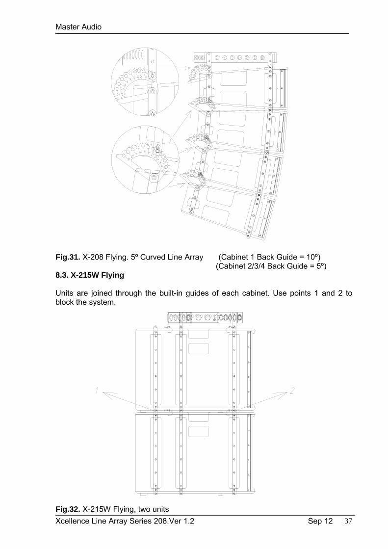
Fig.31. X-208 Flying. 5º Curved Line Array (Cabinet 1 Back Guide = 10º) (Cabinet 2/3/4 Back Guide = 5º)
8.3. X-215W Flying
Units are joined through the built-in guides of each cabinet. Use points 1 and 2 to block the system.
Fig.32. X-215W Flying, two units

Master Audio
Xcellence Line Array Series 208.Ver 1.2 Sep 12 38
Fig.33. X-215W Flying, three units in cardioid configuration
8.4. X-208 + X-215W Flying
It is useful to fly low frequency reinforcement units on the top of the system, as they are the heaviest enclosures. Place the subwoofers as has been explained in section 8.3. Join the last unit of X-215W onto the first unit of X-208 through the FA-X208/215 accessory (see FA-X208/215 specific manual).
Please select “SW” position on X-208 back guide for the upper cabinet
Follow section 8.2 to fly the rest of X-208 units (choose between a flat line array or a curved line array). We recommend 1-2 units of X-215W for each 4 units of X-208.
FA-X208/215
Fig.34. X-208 + X-215W flying with FA-X208/215 accessory
Master Audio
Xcellence Line Array Series 208.Ver 1.2 Sep 12 39
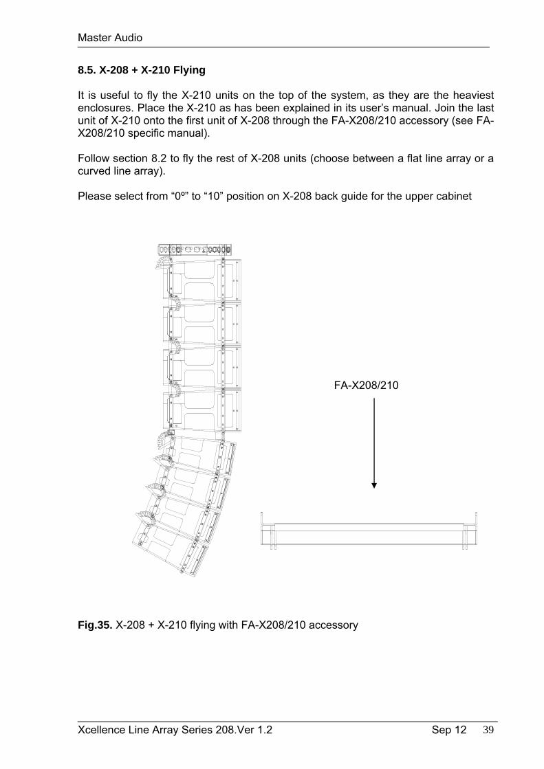
8.5. X-208 + X-210 Flying
It is useful to fly the X-210 units on the top of the system, as they are the heaviest enclosures. Place the X-210 as has been explained in its user’s manual. Join the last unit of X-210 onto the first unit of X-208 through the FA-X208/210 accessory (see FA-X208/210 specific manual).
Follow section 8.2 to fly the rest of X-208 units (choose between a flat line array or a curved line array).
Please select from “0º” to “10” position on X-208 back guide for the upper cabinet
FA-X208/210
Fig.35. X-208 + X-210 flying with FA-X208/210 accessory
Master Audio
Xcellence Line Array Series 208.Ver 1.2 Sep 12 40
9. TECHNICAL SPECIFICATIONS
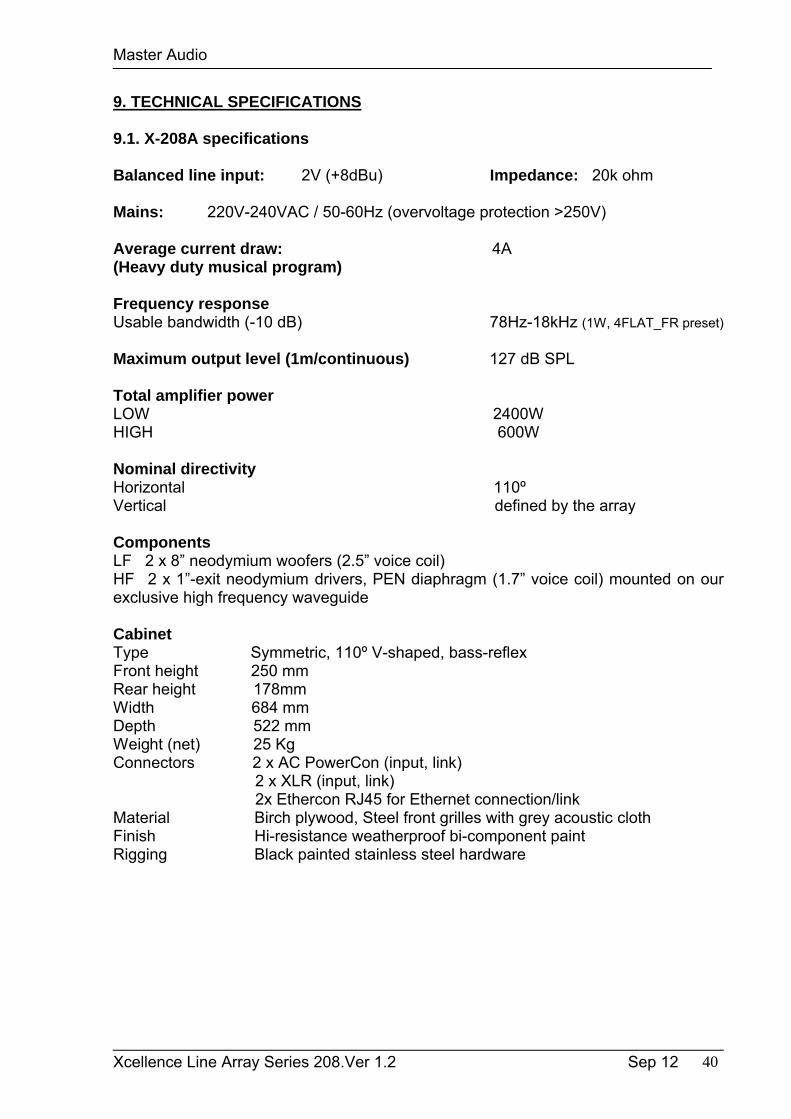
9.1. X-208A specifications
Balanced line input: 2V (+8dBu) Impedance: 20k ohm Mains: 220V-240VAC / 50-60Hz (overvoltage protection >250V)
Average current draw: 4A(Heavy duty musical program)
Frequency responseUsable bandwidth (-10 dB) 78Hz-18kHz (1W, 4FLAT_FR preset) Maximum output level (1m/continuous) 127 dB SPL
Total amplifier powerLOW 2400WHIGH 600W
Nominal directivityHorizontal 110ºVertical defined by the array
ComponentsLF 2 x 8” neodymium woofers (2.5” voice coil)HF 2 x 1”-exit neodymium drivers, PEN diaphragm (1.7” voice coil) mounted on our exclusive high frequency waveguide
CabinetType Symmetric, 110º V-shaped, bass-reflexFront height 250 mmRear height 178mmWidth 684 mmDepth 522 mmWeight (net) 25 KgConnectors 2 x AC PowerCon (input, link) 2 x XLR (input, link) 2x Ethercon RJ45 for Ethernet connection/linkMaterial Birch plywood, Steel front grilles with grey acoustic clothFinish Hi-resistance weatherproof bi-component paintRigging Black painted stainless steel hardware
Master Audio
Xcellence Line Array Series 208.Ver 1.2 Sep 12 41
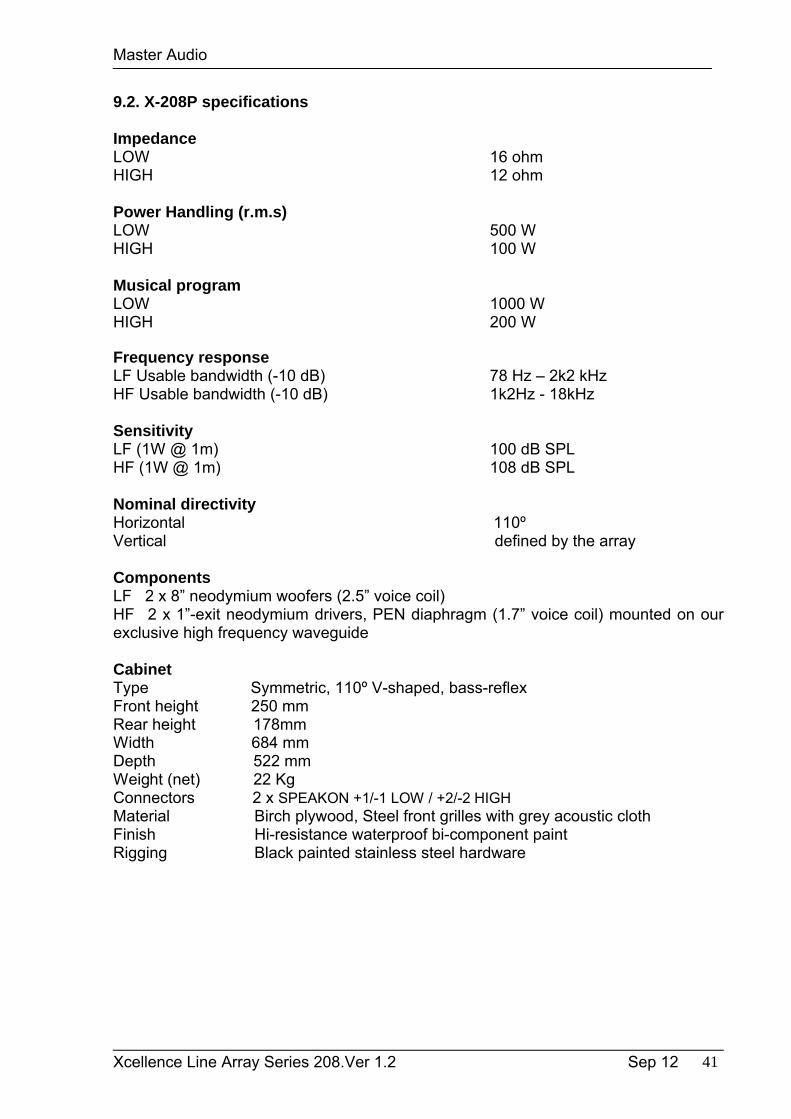
9.2. X-208P specifications
ImpedanceLOW 16 ohmHIGH 12 ohm
Power Handling (r.m.s) LOW 500 W HIGH 100 W
Musical program LOW 1000 W HIGH 200 W
Frequency responseLF Usable bandwidth (-10 dB) 78 Hz – 2k2 kHz HF Usable bandwidth (-10 dB) 1k2Hz - 18kHz
SensitivityLF (1W @ 1m) 100 dB SPL HF (1W @ 1m) 108 dB SPL
Nominal directivity Horizontal 110ºVertical defined by the array
ComponentsLF 2 x 8” neodymium woofers (2.5” voice coil) HF 2 x 1”-exit neodymium drivers, PEN diaphragm (1.7” voice coil) mounted on our exclusive high frequency waveguide
CabinetType Symmetric, 110º V-shaped, bass-reflexFront height 250 mmRear height 178mmWidth 684 mmDepth 522 mmWeight (net) 22 KgConnectors 2 x SPEAKON +1/-1 LOW / +2/-2 HIGHMaterial Birch plywood, Steel front grilles with grey acoustic clothFinish Hi-resistance waterproof bi-component paintRigging Black painted stainless steel hardware
Master Audio
Xcellence Line Array Series 208.Ver 1.2 Sep 12 42
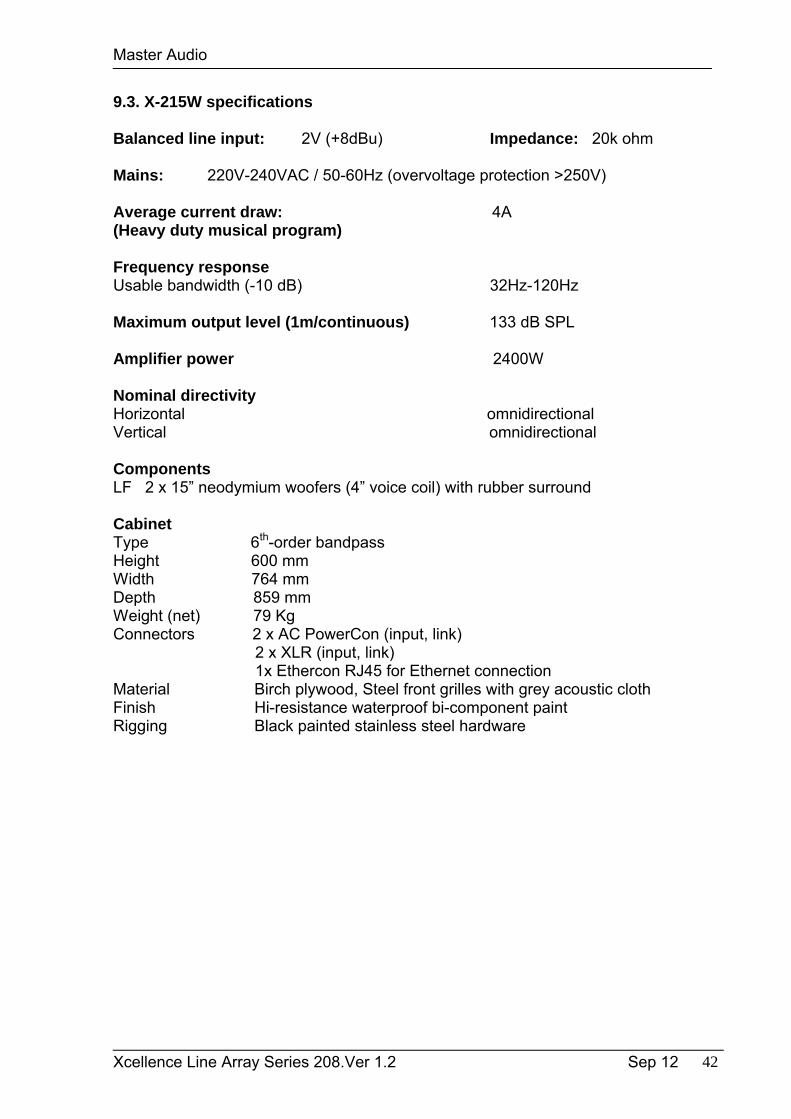
9.3. X-215W specifications
Balanced line input: 2V (+8dBu) Impedance: 20k ohm Mains: 220V-240VAC / 50-60Hz (overvoltage protection >250V)
Average current draw: 4A(Heavy duty musical program)
Frequency responseUsable bandwidth (-10 dB) 32Hz-120Hz
Maximum output level (1m/continuous) 133 dB SPL
Amplifier power 2400W
Nominal directivity Horizontal omnidirectionalVertical omnidirectional
ComponentsLF 2 x 15” neodymium woofers (4” voice coil) with rubber surround
CabinetType 6th-order bandpassHeight 600 mmWidth 764 mmDepth 859 mmWeight (net) 79 KgConnectors 2 x AC PowerCon (input, link) 2 x XLR (input, link) 1x Ethercon RJ45 for Ethernet connection Material Birch plywood, Steel front grilles with grey acoustic clothFinish Hi-resistance waterproof bi-component paintRigging Black painted stainless steel hardware
Master Audio
Xcellence Line Array Series 208.Ver 1.2 Sep 12 43
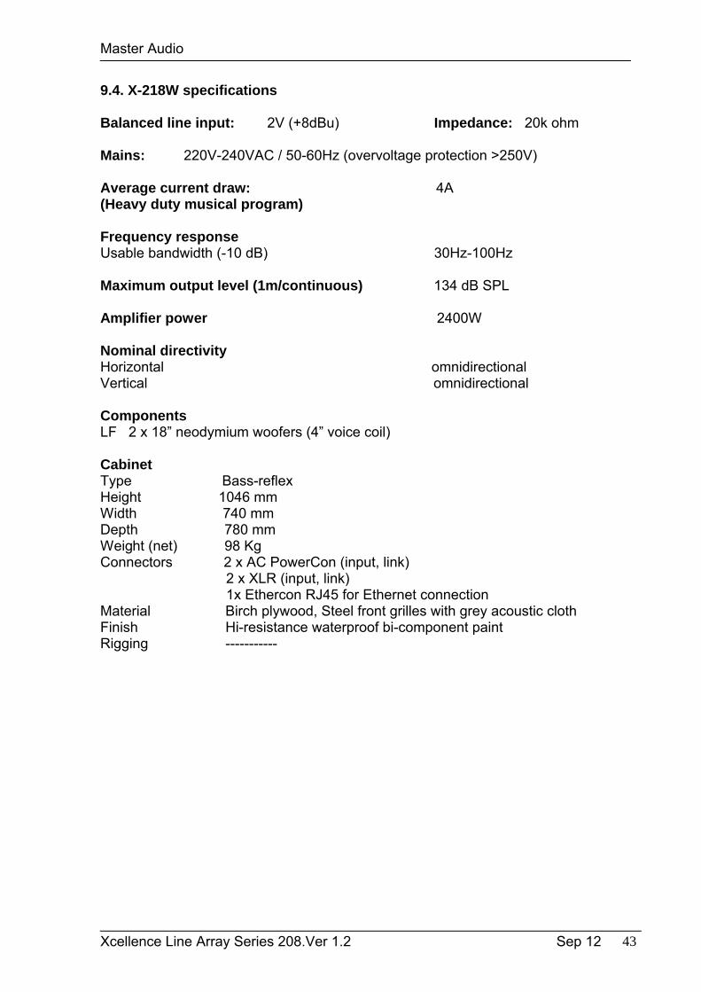
9.4. X-218W specifications
Balanced line input: 2V (+8dBu) Impedance: 20k ohm Mains: 220V-240VAC / 50-60Hz (overvoltage protection >250V)
Average current draw: 4A(Heavy duty musical program)
Frequency responseUsable bandwidth (-10 dB) 30Hz-100Hz Maximum output level (1m/continuous) 134 dB SPL
Amplifier power 2400W
Nominal directivity Horizontal omnidirectionalVertical omnidirectional
ComponentsLF 2 x 18” neodymium woofers (4” voice coil)
CabinetType Bass-reflexHeight 1046 mmWidth 740 mmDepth 780 mmWeight (net) 98 KgConnectors 2 x AC PowerCon (input, link) 2 x XLR (input, link) 1x Ethercon RJ45 for Ethernet connection Material Birch plywood, Steel front grilles with grey acoustic clothFinish Hi-resistance waterproof bi-component paintRigging -----------
Master Audio
Xcellence Line Array Series 208.Ver 1.2 Sep 12 44
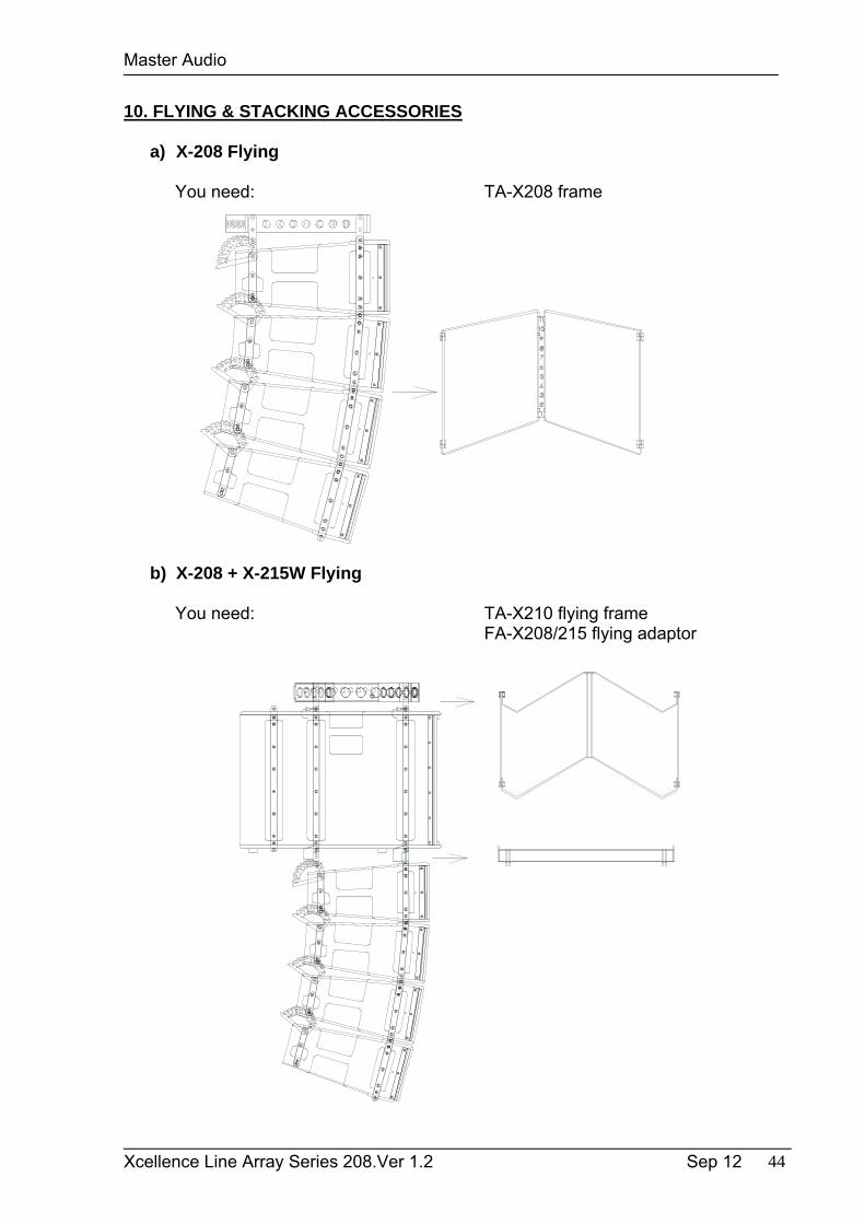
10. FLYING & STACKING ACCESSORIES
a) X-208 Flying
You need: TA-X208 frame
b) X-208 + X-215W Flying
You need: TA-X210 flying frameFA-X208/215 flying adaptor
Master Audio
Xcellence Line Array Series 208.Ver 1.2 Sep 12 45
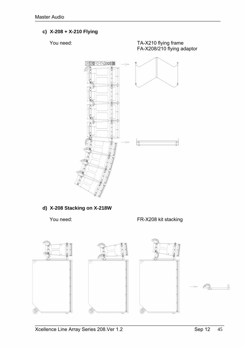
c) X-208 + X-210 Flying
You need: TA-X210 flying frameFA-X208/210 flying adaptor
d) X-208 Stacking on X-218W
You need: FR-X208 kit stacking
Master Audio
Xcellence Line Array Series 208.Ver 1.2 Sep 12 46
11. TIME ALIGNMENT IN PA SYSTEMS
In common PA systems the frequency range is divided into different ranges which are reproduced using different cabinets (subwoofers for the bass range and top cabinets for the mid-high range). This means different locations and positions of the sound sources.
This leads to some interferences in the crossover range, causing notches and peaks in that area. Time alignment (delay) tries to adjust the arrival time of sound so that in the crossover area it arrives at the same time.
Fig.36.This system is not completely aligned because d1 and d2 are not equal.
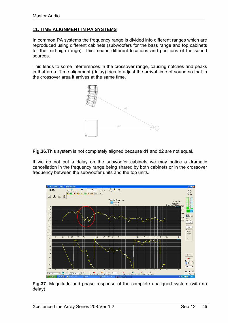
If we do not put a delay on the subwoofer cabinets we may notice a dramatic cancellation in the frequency range being shared by both cabinets or in the crossover frequency between the subwoofer units and the top units.
Fig.37. Magnitude and phase response of the complete unaligned system (with no delay)
Master Audio
Xcellence Line Array Series 208.Ver 1.2 Sep 12 47
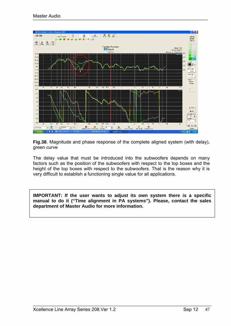
Fig.38. Magnitude and phase response of the complete aligned system (with delay), green curve
The delay value that must be introduced into the subwoofers depends on manyfactors such as the position of the subwoofers with respect to the top boxes and the height of the top boxes with respect to the subwoofers. That is the reason why it isvery difficult to establish a functioning single value for all applications.
IMPORTANT: If the user wants to adjust its own system there is a specific manual to do it (“Time alignment in PA systems”). Please, contact the sales department of Master Audio for more information.
Master Audio
Xcellence Line Array Series 208.Ver 1.2 Sep 12 48
12. TROUBLESHOOTING
No power
Check the device is connected to mains Check mains cable is in good condition.
No sound
Check with the indicators that the signal is being sent from the mixer. Check that the signal cables are in good condition and connected at both ends The mixer output level must not be at minimum. Check that the mixer in not in Mute mode.
Distorted output signal
The system is being saturated with a very high input signal, frequently caused by the mixer overload. Check the output level or mixer gain channels.
Poor bass levels
Check the polarity on the signal connections between the mixer and cabinets. If any of the Pins (1, 2 or 3) have been inverted at the cable ends, this will cause significant performance and sound quality loss.
Noise and Hum
Check that all the connections to the active units are in good condition. Avoid intertwining between mains supply cables or proximity to transformers or Electromagnetic (EMI) emitting devices. Check there is no light intensity regulator in the same AC circuit as the unit. ALWAYS connect the sound and light circuits in different phases.
Overvoltage LED light (RED) Check that the mains voltage is within the limits (230+/-10%), 50/60 Hz