xillybus host application programming guide for...
TRANSCRIPT

Xillybus host application programming guide for Linux
Xillybus Ltd.
www.xillybus.com
Version 2.2
1 Introduction 4
2 Synchronous vs. asynchronous streams 6
2.1 Overview . . . . . . . . . . . . . . . . . . . . . . . . . . . . . . . . . . . 6
2.2 Motivation for asynchronous streams . . . . . . . . . . . . . . . . . . . . 7
2.3 FPGA to host streams . . . . . . . . . . . . . . . . . . . . . . . . . . . . 7
2.4 Host to FPGA streams . . . . . . . . . . . . . . . . . . . . . . . . . . . . 8
2.5 Latency vs. uncertainty . . . . . . . . . . . . . . . . . . . . . . . . . . . 9
3 I/O programming practices 10
3.1 Overview . . . . . . . . . . . . . . . . . . . . . . . . . . . . . . . . . . . 10
3.2 Guidelines for reading data . . . . . . . . . . . . . . . . . . . . . . . . . 11
3.3 Guidelines for writing data . . . . . . . . . . . . . . . . . . . . . . . . . . 13
3.4 Flushing asynchronous downstreams . . . . . . . . . . . . . . . . . . . 15
3.5 Nonblocking I/O and select() . . . . . . . . . . . . . . . . . . . . . . . . 16
3.6 Monitoring the amount of data in DMA buffers . . . . . . . . . . . . . . . 17
4 Continuous high rate I/O 18
4.1 The basics . . . . . . . . . . . . . . . . . . . . . . . . . . . . . . . . . . 18
4.2 Large DMA buffers . . . . . . . . . . . . . . . . . . . . . . . . . . . . . . 19

Xillybus Ltd. www.xillybus.com
4.3 User space RAM buffer . . . . . . . . . . . . . . . . . . . . . . . . . . . 20
4.4 The fifo.c demo application overview . . . . . . . . . . . . . . . . . . . . 21
4.5 fifo.c hacking notes . . . . . . . . . . . . . . . . . . . . . . . . . . . . . . 22
4.6 RAM FIFO functions . . . . . . . . . . . . . . . . . . . . . . . . . . . . . 22
4.6.1 fifo init() . . . . . . . . . . . . . . . . . . . . . . . . . . . . . . . . 23
4.6.2 fifo destroy() . . . . . . . . . . . . . . . . . . . . . . . . . . . . . 24
4.6.3 fifo request drain() . . . . . . . . . . . . . . . . . . . . . . . . . . 24
4.6.4 fifo drained() . . . . . . . . . . . . . . . . . . . . . . . . . . . . . 25
4.6.5 fifo request write() . . . . . . . . . . . . . . . . . . . . . . . . . . 25
4.6.6 fifo wrote() . . . . . . . . . . . . . . . . . . . . . . . . . . . . . . 26
4.6.7 fifo done() . . . . . . . . . . . . . . . . . . . . . . . . . . . . . . . 26
4.6.8 The FIFO BACKOFF define variable . . . . . . . . . . . . . . . . 26
5 Cyclic frame buffers 27
5.1 Introduction . . . . . . . . . . . . . . . . . . . . . . . . . . . . . . . . . . 27
5.2 Adapting the FIFO example code . . . . . . . . . . . . . . . . . . . . . . 27
5.3 Frame dropping and repetition . . . . . . . . . . . . . . . . . . . . . . . 29
6 Specific programming techniques 30
6.1 Seekable streams . . . . . . . . . . . . . . . . . . . . . . . . . . . . . . 30
6.2 Synchronizing streams in both directions . . . . . . . . . . . . . . . . . . 32
6.3 Packet communication . . . . . . . . . . . . . . . . . . . . . . . . . . . . 33
6.4 Emulating hardware interrupts . . . . . . . . . . . . . . . . . . . . . . . 34
6.5 Timeout . . . . . . . . . . . . . . . . . . . . . . . . . . . . . . . . . . . . 35
6.6 Coprocessing / Hardware acceleration . . . . . . . . . . . . . . . . . . . 37
A Internals: How streams are implemented 40
A.1 Introduction . . . . . . . . . . . . . . . . . . . . . . . . . . . . . . . . . . 40
A.2 “Classic” DMA vs. Xillybus . . . . . . . . . . . . . . . . . . . . . . . . . . 40
A.3 FPGA to host (upstream) . . . . . . . . . . . . . . . . . . . . . . . . . . 41
A.3.1 Overview . . . . . . . . . . . . . . . . . . . . . . . . . . . . . . . 41
Xillybus host application programming guide for Linux 2

Xillybus Ltd. www.xillybus.com
A.3.2 Leg #1: Application logic to intermediate FIFO . . . . . . . . . . 42
A.3.3 Leg #2: Intermediate FIFO to DMA buffer . . . . . . . . . . . . . 42
A.3.4 Leg #3: DMA buffer to user software application . . . . . . . . . 43
A.3.5 Conditions for handing over partially filled buffers . . . . . . . . . 44
A.3.6 Examples . . . . . . . . . . . . . . . . . . . . . . . . . . . . . . . 45
A.3.7 Practical conclusions . . . . . . . . . . . . . . . . . . . . . . . . . 46
A.4 Host to FPGA (downstream) . . . . . . . . . . . . . . . . . . . . . . . . 47
A.4.1 Overview . . . . . . . . . . . . . . . . . . . . . . . . . . . . . . . 47
A.4.2 Leg #1: User software application to DMA buffer . . . . . . . . . 47
A.4.3 Leg #2: DMA buffer to Intermediate FIFO . . . . . . . . . . . . . 49
A.4.4 Leg #3: Intermediate FIFO to application logic . . . . . . . . . . 49
A.4.5 An example . . . . . . . . . . . . . . . . . . . . . . . . . . . . . . 49
A.4.6 Practical conclusions . . . . . . . . . . . . . . . . . . . . . . . . . 50
Xillybus host application programming guide for Linux 3

Xillybus Ltd. www.xillybus.com
1Introduction
Xillybus was designed to present the Linux host with a simple and well-known inter-face, having a natural and expected behavior. The host driver generates device filesthat behave like named pipes. They are opened, read from and written to just likeany file, but behave much like pipes between processes or TCP/IP streams. To theprogram running on the host, the difference is that the other side of the stream is notanother process (over the network or on the same computer), but a FIFO in the FPGA.Just like a TCP/IP stream, the Xillybus stream is designed to work well with high-ratedata transfers as well single bytes arriving or sent occasionally.
Since the interface with Xillybus is all through device files that are accessed like justany file, any practical programming language can be used, with no need for a specialmodule, extension or any other adaption. If a file can be opened with the chosenlanguage, it can be used to access the FPGA through Xillybus.
One driver binary supports any Xillybus IP core configuration: The streams and theirattributes are auto-detected by the driver as it’s loaded into the host’s operating sys-tem, and device files are created accordingly. These device files are accessed as/dev/xillybus_something.
Also at driver load, DMA buffers are allocated in the host’s memory space, and theFPGA is informed about their addresses. The number of DMA buffers and their sizeare separate parameters for each stream. These parameters are hardcoded in theFPGA IP core for a given configuration, and are retrieved by the host during the dis-covery process.
A handshake protocol between the FPGA and host makes an illusion of a continuousdata stream. Behind the scenes, DMA buffers are filled, handed over and acknowl-edged. Techniques similar to those used for TCP/IP streaming are used to ensurean efficient utilization of the DMA buffers, while maintaining responsiveness for small
Xillybus host application programming guide for Linux 4

Xillybus Ltd. www.xillybus.com
pieces of data.
Since Xillybus I/O is carried out just like any device file I/O in Linux, there is appar-ently no need for a programming guide, as common programming practices can beemployed.
Even so, communication with FPGA often involves tasks that are not typical to fileI/O. This guide suggests methods to implementing common FPGA-related assign-ments, as well as how to achieve optimal performance. Experienced programmersmay choose different methods with equal success.
Much of this guide is no more than an outline of how robust and efficient I/O is imple-mented in UNIX systems. Those familiar with such techniques may find several partsin this guide redundant, and indeed they are; Xillybus was designed not to invent anynew API, but rather behave like experienced programmers would expect it to.
The examples in this guide are given in plain C, for clarity and because it has a setof functions that are known to be closely related to low-level system calls. The tech-niques described can be implemented in several other languages, including script lan-guages such as Perl and Python, in particular when the requirements for performanceand synchronization between host and FPGA actions are less strict.
Some file I/O can even be done with shell scripts and one-liners.
Xillybus host application programming guide for Linux 5

Xillybus Ltd. www.xillybus.com
2Synchronous vs. asynchronous streams
2.1 Overview
Each Xillybus stream has a flag, which determines whether it behaves synchronouslyor asynchronously. This flag’s value is fixed in the FPGA’s logic.
When a stream is marked asynchronous, it’s allowed to communicate data betweenthe FPGA and the host’s kernel level software without the user space software’s in-volvement, as long as the respective device file is open.
Asynchronous streams have better performance, in particular when the data flow iscontinuous. Synchronous streams are easier to handle, and are the preferred choicewhen tight synchronization is needed between the host program’s actions and whathappens in the FPGA.
In custom IP cores that are generated in the IP Core Factory, the selection betweenmaking each stream synchronous or asynchronous is automatically based upon theinformation about the stream’s intended use, as declared by the tool’s user when“autoset internals” is enabled. If the autoset option is turned off, the user makes thischoice explicitly.
Either way, the “readme” file, included in the bundle that is downloaded from the IPCore Factory, specifies synchronous or asynchronous flag for each stream (amongother attributes).
In all demo bundles, the xillybus read * and xillybus write * streams are asynchronous.xillybus mem 8 is seekable and therefore synchronous.
Xillybus host application programming guide for Linux 6

Xillybus Ltd. www.xillybus.com
2.2 Motivation for asynchronous streams
Multitasking operating systems such as Linux and Microsoft Windows are based uponCPU time sharing: Processes get time slices of the CPU, with some scheduling algo-rithm deciding which process gets the CPU at any given moment.
Even though there’s a possibility to set priorities for processes, there is no guaran-tee that a process will run continuously or that the preemption periods have a lim-ited duration, not even on a multiprocessor computer. The underlying assumption ofthe operating system is that any process can accept any period of CPU starvation.Real-time orientated applications (e.g. sound applications and video players) have nodefinite solution to this problem. Instead, they rely on a certain de-facto behavior ofthe operating system, and make up for the preemption periods with I/O buffering.
Asynchronous streams address this issue by allowing a “background” flow of datawhile the application is either preempted or busy with other tasks. The exact signifi-cance of this for streams in either direction is discussed next.
2.3 FPGA to host streams
In the upstream direction (FPGA to host), an asynchronous stream fills the host’s DMAbuffers whenever possible. That is, when the file is open, data is available and thereis free space in the DMA buffers.
On the other hand, if the stream is synchronous, the IP core’s logic in the FPGAwill not fetch data from the user application logic unless the user application has anoutstanding request to read that data from the file descriptor.
Synchronous streams should be avoided in high-bandwidth applications, mainly forthese two reasons:
• The data flow is interrupted while the application is preempted or doing some-thing else, so the physical channel remains unutilized during certain time peri-ods. In most cases, this leads to a significant bandwidth performance hit.
• The FIFO between the application logic and the IP core’s logic in the FPGA mayoverflow during these time gaps. For example, if its fill rate is 100 MB/sec, atypical 2 kByte FPGA FIFO goes from empty to full in around 0.02 ms. Practi-cally, this means that any preemption of the user space program will make theFPGA’s FIFO overflow.
Despite these drawbacks, synchronous streams are useful when the time at which
Xillybus host application programming guide for Linux 7

Xillybus Ltd. www.xillybus.com
the data was collected at the FPGA is important. In particular, memory-like interfacesrequire a synchronous interface.
Data that has been received by the Xillybus FPGA IP core is available for readingimmediately by the host’s user space application, regardless of whether the streamis synchronous or asynchronous. There’s a mechanism handling partially filled DMAbuffers, making this issue transparent to the user space application, thus avoidingunnecessary blocking.
2.4 Host to FPGA streams
In the downstream direction (host to FPGA), the stream being asynchronous meansthat the host application’s calls will return immediately most of the time. More pre-cisely, the calls to functions writing to the device file will return immediately if the datacan be stored entirely in the DMA buffers. The data is then transmitted to the FPGAat the rate requested by the user application logic at the FPGA, with no involvementof the host application.
For asynchronous streams to the FPGA, the data is sent to the FPGA only when oneof these happen:
• The current DMA buffer is full (there are several buffers for each stream)
• The file descriptor is explicitly flushed (see paragraph 3.4)
• The file descriptor is closed.
• A timer expires, forcing an automatic flush if nothing has been written to thestream for a specific amount of time (typically 10 ms).
On the other hand, if the stream is synchronous, a call to the low-level function writingto the device file will not return until all data has reached the user application’s logicin the FPGA. In a typical application, the return of this low-level function indicates thatthe data has arrived to the FIFO in the FPGA, which is connected by the user to theIP core.
IMPORTANT:
Higher-level I/O functions, such as fwrite(), involve a buffer layer created by thelibrary functions. Hence fwrite() and similar functions may return before the datahas arrived at the FPGA, even for synchronous streams.
Xillybus host application programming guide for Linux 8

Xillybus Ltd. www.xillybus.com
Synchronous streams should be avoided in in high-bandwidth applications, mainly forthese two reasons:
• The data flow is interrupted while the application is preempted or doing some-thing else, so the physical channel remains unutilized during certain time seg-ments. In most cases, this leads to a significant bandwidth performance hit.
• The FIFO between application logic and IP core’s logic in the FPGA may un-derflow during these time gaps. For example, if its drain rate is 100 MB/sec, atypical 2 kByte FPGA FIFO goes from full to empty in around 0.02 ms. Practi-cally, this means that any preemption of the user space program will make theFPGA’s FIFO underflow.
Despite these drawbacks, synchronous streams are useful when it’s important for theapplication to know that the data has arrived to the FPGA. This is the case whenthe stream is used to transmit commands that must be executed before some otheroperation takes place (e.g. configuration of the hardware).
2.5 Latency vs. uncertainty
A common mistake it to require a low latency on asynchronous streams for the sakeof synchronization between data. For example, if the application is a modem, there isusually a natural need to synchronize between received and transmitted samples.
This often leads to a misconceived design, based upon the notion the uncertainty inthe synchronization is necessarily smaller than the total latency. To keep the uncer-tainty low, the latency, and hence buffering, is made as small as possible, leading toan overall system with tough realtime requirements.
With Xillybus, the synchronization is easily made perfect (at the level of a single sam-ple), as explained in paragraph 6.2. The limitation on latency is therefore derived fromthe need to close loops, if there is such a need.
For a modem, the maximal latency has an impact on how quickly the underlying datasource responds to data sent to it. In a camera application, the host may program thecamera to adjust the shutter speed to compensate for changing light conditions. Dataarriving with latency slows down this control loop. These are the real considerationsthat need to be taken, and still, they are usually significantly less stringent than thosederived from mixing timing uncertainty with latency.
Xillybus host application programming guide for Linux 9

Xillybus Ltd. www.xillybus.com
3I/O programming practices
3.1 Overview
Xillybus works properly with any programming language which is able to access files,and any file access API is suitable.
In this guide there’s an emphasis on the low-level API set, based upon functions suchas open(), read(), write() and close(). This set is chosen over other well-known sets(e.g. fopen(), fwrite(), fprintf() etc.) because the low-level API’s functions have noextra layer of buffers. These buffers can have a positive effect on performance, butthey also detach the timing and amounts of actual I/O operations from the functioncalls issued by the program.
This is less important when data is streaming constantly and no direct relation isexpected between software operations and hardware I/O.
An extra buffer layer can also cause confusion, making it look like there’s a softwarebug where there isn’t. For example, a call to fwrite() can merely store the data in aRAM buffer without performing any I/O operation until the file is either closed or fflush()is called. A developer not aware of this may be mislead to think that the fwrite() failedbecause nothing happened on the FPGA side, when in fact the data is waiting in thebuffer.
This section describes the recommended UNIX programming practices, using the low-level C run-time library functions. This elaboration in given here for the sake of com-pleteness, as there is nothing specific to Xillybus about any of these practices.
The code snippets are taken from the demo applications described in Getting startedwith Xillybus on a Linux host.
Xillybus host application programming guide for Linux 10

Xillybus Ltd. www.xillybus.com
3.2 Guidelines for reading data
Assuming that the variables have been declared as follows,
int fd, rc;
unsigned char *buf;
the device file is opened with the low-level open (the file descriptor is in integer format):
fd = open("/dev/xillybus_ourdevice", O_RDONLY);
if (fd < 0) {
perror("Failed to open devfile");
exit(1);
}
A “Device or resource busy” (errno = EBUSY) error will be issued if the device file isalready opened for read by another process (non-exclusive file opening is availableon request). If “No such device” (errno = ENODEV) occurs, it’s most likely an attemptto open a write-only stream.
With the file opened successfully and buf pointing at an allocated buffer in memory,data is read with
while (1) {
rc = read(fd, buf, numbytes);
where numbytes is the maximal number of bytes to read.
The returned value, rc, contains the number of bytes actually read (or a negativevalue if the call completed abnormally).
IMPORTANT:
There is no guarantee that all requested bytes were read from the file, even on asuccessful return of read(). It’s the caller’s responsibility to call read() again if thecompleted amount was unsatisfactory.
The call to read() should be followed by checking its return value as shown below(“continue” and “break” statements assume a while-loop context):
Xillybus host application programming guide for Linux 11

Xillybus Ltd. www.xillybus.com
if ((rc < 0) && (errno == EINTR))
continue;
if (rc < 0) {
perror("read() failed");
break;
}
if (rc == 0) {
fprintf(stderr, "Reached read EOF.\n");
break;
}
// do something with "rc" bytes of data
}
The first if-statement checks if read() returned prematurely because of an interrupt.This is a result of the process receiving a signal from the operating system.
This is not an error really, but a condition forcing the I/O driver to return control to theapplication immediately. The use of the EINTR error number is just a way to tell thecaller that there was no data read. The program responds with a “continue” statement,resulting in a renewed attempt to call read() with the same parameters.
If there is some data in the buffer when the interrupt arrives, the driver will return thenumber of bytes already read in rc. The application will not know an interrupt hasarrived, and according to UNIX programming convention, it has no reason to care: Ifthe signal requires action (e.g. SIGINT resulting from a CTRL-C on keyboard), eitherthe operating system or a registered signal handler will respond as necessary.
Note that some signals shouldn’t have any effect on the execution flow, so if interruptsaren’t detected as shown above, the program may suddenly report an error for noapparent reason.
Handling the EINTR case is also necessary to allow the process to be stopped (aswith CTRL-Z) and resumed properly.
The second if-statement terminates the loop if a real error has occurred after reportinga user-readable error message.
The third if-statement detects if end of file has been reached, which is indicated bya zero read byte count. When reading from a Xillybus device file, this can only hap-pen as a result of the application logic raising the stream’s eof pin on the IP core’sinterface.
Xillybus host application programming guide for Linux 12

Xillybus Ltd. www.xillybus.com
3.3 Guidelines for writing data
Assuming that the variables have been declared as follows,
int fd, rc;
unsigned char *buf;
the device file is opened with the low-level open (the file descriptor is in integer format):
fd = open("/dev/xillybus_ourdevice", O_WRONLY);
if (fd < 0) {
perror("Failed to open devfile");
exit(1);
}
A “Device or resource busy” (errno = EBUSY) error will be issued if the device file isalready opened for write by another process (non-exclusive file opening is availableon request). If “No such device” (errno = ENODEV) occurs, it’s most likely an attemptto open a write-only stream.
With the file opened successfully and buf pointing at an allocated buffer in memory,data is written with
while (1) {
rc = write(fd, buf, numbytes);
where numbytes is the maximal number of bytes to be written.
The returned value, rc, contains the number of bytes actually written (or a negativevalue if the call completed abnormally).
IMPORTANT:
There is no guarantee that all requested bytes were written to the file, even on asuccessful return of write(). It’s the caller’s responsibility to call write() again if thecompleted amount was unsatisfactory.
The call to write() should be followed by checking its return value as shown below(“continue” and “break” statements assume a while-loop context):
Xillybus host application programming guide for Linux 13

Xillybus Ltd. www.xillybus.com
if ((rc < 0) && (errno == EINTR))
continue;
if (rc < 0) {
perror("write() failed");
break;
}
if (rc == 0) {
fprintf(stderr, "Reached write EOF (?!)\n");
break;
}
// do something with "rc" bytes of data
}
The first if-statement checks if write() returned prematurely because of an interrupt.This is a result of the process receiving a signal from the operating system.
This is not an error really, but a condition forcing the I/O driver to return control tothe application immediately. The use of the EINTR error number is just a way to tellthe caller that there was no data written. The program responds with a “continue”statement, resulting in a renewed attempt to call write() with the same parameters.
If some data was written before the interrupt arrived, the driver will return the numberof bytes already written in rc. The application will not know an interrupt has arrived,and according to UNIX programming convention, it has no reason to care: If thesignal requires action (e.g. SIGINT resulting from a CTRL-C on keyboard), eitherthe operating system or a registered signal handler will respond as necessary.
Note that some signals shouldn’t have any effect on the execution flow, so if interruptsaren’t detected as shown above, the program may suddenly report an error for noapparent reason.
Handling the EINTR case is also necessary to allow the process to be stopped (aswith CTRL-Z) and resumed properly.
The second if-statement terminates the loop if a real error has occurred after reportinga user-writable error message.
The third if-statement detects if the end of file has been reached, which is indicatedby the a zero write byte count. When writing to a Xillybus device file, this should neverhappen
Xillybus host application programming guide for Linux 14

Xillybus Ltd. www.xillybus.com
3.4 Flushing asynchronous downstreams
As mentioned in paragraph 2.4, data written to an asynchronous stream is not nec-essarily sent immediately to the FPGA, unless a DMA buffer is full (there are severalDMA buffers). This behavior improves performance by making sure that the allocatedbuffer space is utilized. This also improves the efficiency of the packets sent on thePCI Express or AXI bus.
Streams to the FPGA are automatically flushed when the file descriptor is closed orafter a short idle period. The call to close() is delayed until all data has arrived atthe FPGA in a manner similar to the way write() calls are delayed on synchronousstreams. The significant difference is that close() waits up to one second for the flushto complete. If the flush isn’t completed by then, close() returns anyhow, and issues awarning message in the system log.
It’s also possible to flush an asynchronous stream explicitly, by calling write() with azero-length buffer, i.e.
while (1) {
rc = write(fd, NULL, 0);
if ((rc < 0) && (errno == EINTR))
continue; // Interrupted. Try again.
if (rc < 0) {
perror("flushing failed");
break;
}
break; // Flush successful
}
Please note the following:
• Unlike close(), a zero-count write() returns immediately, regardless of when thedata is consumed on the FPGA.
• Since no data is read from the buffer, the buffer argument in the write() call cantake any value, including NULL, as demonstrated above.
• The UNIX manual page doesn’t define what write() with a zero count should do,leaving the choice to each device driver. This method for flushing is Xillybus-specific.
Xillybus host application programming guide for Linux 15

Xillybus Ltd. www.xillybus.com
• Using higher-level API with a zero buffer may not have any effect at all. Forexample, calling fwrite() to write zero bytes may simply return with nothing done,since what this function usually does is adding the data to a buffer created bythe C run-time library.
• fflush() is irrelevant: It flushes the higher-level buffer, but doesn’t send a flushcommand to the low-level driver.
• There is no need to flush streams in the other direction (from FPGA to host)since these streams are automatically flushed when a host’s attempt to readdata is about to block.
3.5 Nonblocking I/O and select()
Even though not recommended, the Xillybus driver for Linux supports nonblockingcalls and the select() function. Note that the Windows driver doesn’t support anythingsimilar, so using this functionality makes the application harder to port if necessary.
Using nonblocking I/O or select() is typically a sign of poor software design. Theirimplementation in Xillybus is merely a result of market demand. The recommendedway to handle multiple sources is with multiple threads (and preferably RAM FIFOs)as demonstrated in the fifo.c example program, discussed in paragraph 4.4.
Calls to select(), pselect() and poll() can be used like any UNIX file descriptor, for readand write alike.
Nonblocking calls and select() are not enabled in FPGA’s IP cores that have been setup for Windows only in the IP Core Factory.
For the sake of completeness, we shall revisit the code outline for reading data in para-graph 3.2, using nonblocking reads. This code merely demonstrates the conventionalflow for any nonblocking read from a file in UNIX.
The file is opened with the O NONBLOCK flag:
fd = open("/dev/xillybus_ourdevice", O_RDONLY | O_NONBLOCK);
if (fd < 0) {
perror("Failed to open devfile");
exit(1);
}
There is no difference in how the file is read, the arguments or the meaning of thereturn value:
Xillybus host application programming guide for Linux 16
Xillybus Ltd. www.xillybus.com
while (1) {
rc = read(fd, buf, numbytes);
But there is now another check on the return values: If rc is negative and EAGAIN isgiven as the error code, this means there was nothing to read (more precisely, thereis no data in the DMA buffers, and the FIFO connected to the IP core in the FPGA isempty).
if ((rc < 0) && (errno == EINTR))
continue;
if ((rc < 0) && (errno == EAGAIN)) {
// do something else
continue;
}
if (rc < 0) {
perror("read() failed");
break;
}
if (rc == 0) {
fprintf(stderr, "Reached read EOF.\n");
break;
}
// do something with "rc" bytes of data
}
Note that the code above doesn’t make sense unless something meaningful is donewhen the call returns with an EAGAIN. Otherwise it just wastes CPU time by spinningin the while loop, instead of blocking when there is no data to read.
For nonblocking writing, make the respective changes in the example in paragraph3.3.
3.6 Monitoring the amount of data in DMA buffers
This topic is discussed in Xillybus FPGA designer’s guide, in the section named “Mon-itoring the amount of buffered data”.
Xillybus host application programming guide for Linux 17

Xillybus Ltd. www.xillybus.com
4Continuous high rate I/O
4.1 The basics
There are four practices that are nearly essential to achieve a high-rate continuousdata flow between the host and the FPGA:
• Using asynchronous streams
• Making sure the DMA buffers are large enough to compensate for time gapsbetween the user space application’s I/O operations
• Having the user space application read data from the device file as soon asthere is data available, or write data to it as soon as there is buffering spaceavailable (depending on the direction).
• Never closing and reopening the device files while the FPGA keeps pumping ordraining data.
Monitoring how much data is held in the DMA buffers at any given time is discussedin Xillybus FPGA designer’s guide, in the section named “Monitoring the amount ofbuffered data”.
The first practice of using asynchronous streams is discussed in section 2. The sec-ond and third are discussed in the remainder of this section.
To understand the the fourth item, recall that the advantage of asynchronous streamsis that data runs between the FPGA and host without the user space application’sintervention by virtue of DMA. This flow is stopped when the file is closed.
On a stream to the FPGA, the data is flushed and then the file closed, so the FIFO onthe FPGA will be drained until the file is reopened and written to again.
Xillybus host application programming guide for Linux 18

Xillybus Ltd. www.xillybus.com
As for streams from the FPGA, closing the file leads to loss of any data in the pipegoing from the application logic in the FPGA to the user space application in the host(i.e. the FPGA’s FIFO and DMA buffers on the host). The only way to avoid this lossis draining this pipe of data, and thus losing the buffering capabilities it has.
A common mistake is to use the EOF capability to mark data chunks (e.g. completevideo frames) by forcing the host to close and reopen the device file at known bound-aries, but this significanly increases the risk for data overflows at the FPGA.
It’s important to keep in mind that the operating system may preempt a user spaceapplication at any given moment, so time gaps of several, and sometimes tens ofmilliseconds can occur between subsequent function calls in a program.
4.2 Large DMA buffers
One of the greatest challenges in transferring data at a high rate between the FPGAand host is to maintain a continuous flow. In applications involving data acquisitionand playback, an overflow or shortage of data renders the system nonfunctional. Thecommon way to avoid this is by allocating large RAM buffers for DMA transfers on thehost. These buffers compensate for the gaps in time, during which the application isn’tavailable to handle data transfers.
Xillybus allows allocation of huge DMA buffers, but this memory must be allocatedfrom the pool of the operating system’s kernel RAM. Typically, the addressing spaceof such memory is limited to 1 GB by the Linux operating system, even if the totalRAM available is significantly larger. In systems with a total of less than 1 GB RAM,(embedded Linux in particular), all memory may be used for DMA buffers.
The DMA buffers are allocated when the Xillybus driver is loaded (typically early inthe boot process) and is freed only when the driver is unloaded from the kernel (usu-ally during system shutdown). When the buffers are huge, this usually means that asignificant part of the kernel’s RAM pool is occupied by the DMA buffers. It’s a fairlyreasonable setting, since the application using these buffers is likely to be the mainpurpose of the machine it’s running on.
A potential problem with huge buffers is that since the DMA buffers are seen directly byhardware, they must occupy continuous segments of physical RAM. This is contraryto a buffer allocated in a userspace program, which is continuous in virtual addressspace, but can be spread all over the physical address space, or even not occupy anyphysical RAM at all.
The pool of available memory becomes fragmented as the operating systems runs.
Xillybus host application programming guide for Linux 19

Xillybus Ltd. www.xillybus.com
This is why the Xillybus driver allocates its buffers as soon as possible, and retainsthem even when the not actively used. Attempting to unload the driver and reload it ata later stage may fail for the same reason.
Precautions should however be taken to avoid a shortage of kernel RAM. Xillybus’IP Core Factory’s automatic memory allocation (“autoset internals”) algorithm is de-signed not to consume more than 50% of the relevant memory pool, e.g. 512 MB fora PC-oriented target, based upon the assumption that a modern PC has more than1 GB of RAM installed. It’s probably safe to go as high as 75% as well, which can bedone by setting the buffer sizes manually.
Overallocation of buffers may lead to system instability. In particular, the operatingsystem is likely to kill processes apparently randomly, whenever it fails to allocateRAM from the kernel pool.
4.3 User space RAM buffer
For applications that require buffers larger than 512 MB, it’s recommended to do someof the buffering in user space RAM.
It may seem counterintuitive that the problem of I/O continuity can be solved by allo-cating a huge buffer in the userspace application. Indeed, this solution doesn’t helpwhen the OS starves the application of CPU time. But if the scheduler is fairly welldesigned and the priorities are set right, a user space application will get its CPU sliceoften enough, even on a loaded computer. Certain Linux kernels have had problemswith this, in particular under heavy disk load, but this was considered a bug, whichhas been solved in recent kernels.
It’s important to pay attention to the first fill of the buffer: Modern operating systemsdon’t allocate any physical RAM when a user application requests memory. Instead,they just set up the memory page tables to reflect the memory allocation. Actualphysical memory is allocated only when the application attempts to use it. This isa brilliant method for saving resources, but can have a disastrous impact on a dataacquisition application: For example, consider what happens when data begins torush in from a data source. The application writes the data to the buffer just allocated,but each time a new memory page is accessed, the operating system needs to get anew physical memory page. If there happens to be free physical RAM, or if there is aquick way to release physical memory (e.g. disk buffers which are already in sync withthe disk), this memory juggling can go by unnoticed. But in the absence of immediatesources of physical RAM, disk operations may have to take place (RAM swapping todisk or flushing disk buffers), which can halt the application for too long.
Xillybus host application programming guide for Linux 20
Xillybus Ltd. www.xillybus.com
The really bad news is that the ability to take the initial load of data depends onthe overall system’s state. Hence a program that usually works may suddenly fail,because some other program just did something data intensive on the same computer.
The natural solution is memory locking: mlock() tells the operating system that a cer-tain chunk of (virtual) memory must be held in physical RAM. This forces allocation ofphysical memory immediately, so if disk operations are needed to complete the call, itmay take some time to return.
The operating system is reluctant to lock large chunks of RAM, as this impacts theoverall OS’ performance. In most cases, there’s a need to raise some limit in the shellor set up configuration files.
4.4 The fifo.c demo application overview
Among the demo applications, which can be downloaded for Linux and Windows,there’s one called “fifo.c” (for more about the demo applications, see Getting startedwith Xillybus on a Linux host). It’s an example of how to implement a RAM FIFO usingtwo threads, and has been compiled and tested as 32-bit and 64-bit executables.
The purpose of this program is to test fast streams, where a RAM FIFO is necessaryto maintain a buffer larger than the 512 MB, that can be allocated as DMA buffers.
It can also form a basis for modification and adoption in custom target applications.It’s designed with no mutexes, so no thread ever goes to sleep just because anotherthread holds the lock. Threads will sleep, of course, when the FIFO’s state requiresblocking (e.g. a read is requested from an empty FIFO). This mutex-less design re-quires careful use of the API functions, as they’re not reentrant. This is however noissue in a simple writer-reader thread setting.
To run it for acquisition of data from a device file into a disk file with a 128 MB buffer,type something like (Linux):
$ ./fifo 134217728 /dev/xillybus_async > dumpfile
or in Windows:
> fifo 134217728 \\.\xillybus_async > dumpfile
If no file name is given as the second argument, the program reads from standardinput.
Xillybus host application programming guide for Linux 21

Xillybus Ltd. www.xillybus.com
There’s probably a need to lift the limit on locked memory, using ’limit -l’ on shellprompt, with root privileges (possibly use su - your-username as root to drop yourprivileges back and retain the relaxed limit). For a constant change in the limit, referto your Linux distribution’s docs.
The program creates three threads:
• read thread() reads from standard input (or the file given in the command line)and writes the data into the FIFO
• write thread() reads from the FIFO and writes to standard output
• status thread() prints a status line to standard error recurrently
The third thread has no functional significance, and can be eliminated. It’s also possi-ble to have one of the read/write functionalities running in the main thread. For exam-ple, in a data acquisition application, it may be natural to launch only read thread() tomove data from the file descriptor to the FIFO, but consume the data from the FIFO inthe main application thread.
4.5 fifo.c hacking notes
If you want to modify the program, here are a few things to keep in mind:
• The fifo * functions are not reentrant. It’s safe to use them in separate threadswhen each thread has its exclusive set of functions (which is a natural use).
• fifo init() can take time to return, and should be called before an asynchronousXillybus file stream is opened.
• The read and write threads in the applications always attempt the maximal num-ber of bytes allowed in their I/O requests. This can be problematic in somecases, e.g. when the I/O source is /dev/zero and the sink is /dev/null. Both willcomplete the entire request in one go, so the FIFO will go from completely emptyto completely full and over again. In such cases, it’s more sensible to limit therequested byte count in calls to I/O functions.
4.6 RAM FIFO functions
Except for hacking the fifo.c example, it’s possible to adopt a group of functions fromthe source code.
Xillybus host application programming guide for Linux 22

Xillybus Ltd. www.xillybus.com
A section of FIFO API functions is clearly distinct in the fifo.c file. These functions canbe used in custom applications, following the example and according to the functions’description below.
IMPORTANT:
Even though the fifo * functions are intended for use in a multi-threaded environ-ment, these functions are not reentrant . This means that one thread should callfunctions related to reading from the FIFO, and another thread should do writes,so each thread calls its separate set of functions.
Except for an initializer, destroyer and a thread join helper, the API has four functionsfor reading and writing, two for each direction. Neither of these functions actuallyaccess the data in the FIFO; they merely maintain the FIFO’s state and supply theinformation necessary to perform reads, writes, memory copies etc.
The intended workflow: The thread reading from the FIFO calls fifo request drain(),which returns information about how many bytes can be read, and a pointer fromwhich data can be read. If the FIFO is empty, the thread will sleep until data arrives.
The user application then makes whatever use it needs with the data pointed to. Afterfinishing to consume some or all of the data (write to a file, copy data, run somealgorithm etc.), it calls fifo drained() to inform the FIFO API how many bytes wereactually consumed. The API releases the relevant portion of memory in the FIFO. Ifthe writing user application thread was blocking because the FIFO was full, it is wokenup.
Note that the user application doesn’t ask for a specific number of bytes. Rather,fifo request drain() tells the application how many bytes can be consumed, and theapplication reports back how many it chose to consume in fifo drained().
As for the opposite direction, a similar approach is taken: The writing thread callsfifo request write(), which returns the number of bytes that can be written to the FIFO,or blocks if the FIFO is full. The user application writes to the address it got fromfifo request write() as many bytes it needs to write (but not more than fifo request write()allowed it to) and then reports back what it did to fifo wrote().
We’ll now go through each of these functions in detail.
4.6.1 fifo init()
fifo init(struct xillyfifo *fifo, unsigned int size) – This function initializes the FIFO infor-mation structure and allocates memory for the FIFO as well. It also attempts to lock
Xillybus host application programming guide for Linux 23

Xillybus Ltd. www.xillybus.com
the FIFO’s virtual memory to physical RAM, making it ready for immediate fast writingand preventing it from being swapped to disk.
fifo init() allocates memory for a buffer of size bytes. size can be any integer (i.e.doesn’t have to be a power of two) but a multiple of what the system considers int isrecommended.
Note that this function can take several seconds to return: The request for a largeportion of physical RAM may force the operating system to swap other processes’RAM pages to disk, or force disk cache flushing. In both cases, fifo init() may have towait for many megabytes of data written to disk before returning.
Returns zero on success, nonzero otherwise.
4.6.2 fifo destroy()
Frees the FIFO’s memory after unlocking it, and releases thread synchronization re-sources. This function should be called when the main program exits, because eventhough the thread synchronization resources are released automatically in currentimplementations of Linux, their API doesn’t guarantee this.
This function is of void type (hence returns nothing).
4.6.3 fifo request drain()
fifo request drain(struct xillyfifo *fifo, struct xillyinfo *info) – Supplies a pointer to readdata from the FIFO as info->addr, and informs how many bytes can be read, beginningfrom that pointer, in info->bytes.
The info structure must not be the same used for calls to fifo request write(). Athread local variable is the straightforward choice.
IMPORTANT:
The number of bytes returned does not indicate how much data is left for readingin the FIFO: It may also reflect the number of bytes left until the end of the FIFO’smemory buffer, so a significantly lower byte count is possible as the pointer ap-proaches its wrap to the beginning of the buffer.
The function also sets fifo->position to indicate the FIFO’s current read position as avalue between 0 and size-1, size as given in fifo init(). A nonzero fifo->slept indicatesthat the FIFO was empty upon invocation.
Xillybus host application programming guide for Linux 24

Xillybus Ltd. www.xillybus.com
Returns the number of bytes allowed for write (same as info->taken), or zero if fifo done()has been called and the FIFO is empty.
4.6.4 fifo drained()
fifo drained(struct xillyfifo *fifo, unsigned int req bytes) – This function changes theFIFO’s state to reflect the consumption of req bytes bytes. If fifo request write() wasblocking because the FIFO was full, it will we woken up.
IMPORTANT:
There is no sanity check on req bytes. It’s the user application’s responsibility tomake sure that req bytes is not larger than info->bytes returned by the last call tofifo request drain().
This function is of void type (hence returns nothing).
4.6.5 fifo request write()
fifo request write(struct xillyfifo *fifo, struct xillyinfo *info) – Supplies a pointer to writedata to the FIFO as info->addr, and informs how many bytes can be written, beginningfrom that pointer, in info->bytes.
The info structure must not be the same used for calls to fifo request drain(). Athread local variable is the straightforward choice.
IMPORTANT:
The number of bytes returned does not indicate how much data is left for writingin the FIFO: It may also reflect the number of bytes left until the end of the FIFO’smemory buffer, so a significantly lower byte count is possible as the pointer ap-proaches its wrap to the beginning of the buffer.
The function also sets fifo->position to indicate the FIFO’s current write position as avalue between 0 and size-1, size as given in fifo init(). A nonzero fifo->slept indicatesthat the FIFO was full upon invocation.
Returns the number of bytes allowed for write (same as info->taken), or zero if fifo done()has been called, even if the FIFO is not full: There is no point writing data into a FIFOthat will never be read.
Xillybus host application programming guide for Linux 25

Xillybus Ltd. www.xillybus.com
4.6.6 fifo wrote()
fifo wrote(struct xillyfifo *fifo, unsigned int req bytes) – This function changes the FIFO’sstate to reflect the insertion of req bytes bytes. If fifo request drain() was blocking be-cause the FIFO was empty, it will we woken up.
IMPORTANT:
There is no sanity check on req bytes. It’s the user application’s responsibility tomake sure that req bytes is not larger than info->bytes returned by the last call tofifo request write().
This function is of void type (hence returns nothing).
4.6.7 fifo done()
This function is optional for use, and helps the application to quit gracefully if eitherof the read or write threads has finished. It merely sets a flag in the FIFO’s structureand wakes up both threads if they were sleeping. By doing so, the fifo request drain()will return zero rather than blocking if the FIFO is empty, and fifo request write() willreturn zero regardless.
Call this function when the data source feeding the pipe has ended (e.g. EOF reached)or when the data sink is no longer receptive (e.g. a broken pipe).
4.6.8 The FIFO BACKOFF define variable
Sometimes it’s not desirable to let the FIFO get full to the last byte. Even though thereis no apparent reason avoiding that, buggy I/O drivers may clutter the bytes sharingthe 32-bit boundary of the last byte written to. Just to have this clear, the Xillybusdrivers do not have such bug.
To avoid this rare but possible problem, FIFO BACKOFF can be set to 8, so the lastbyte written to the FIFO never shares a 64-bit word with the first valid byte for read.This is a rather far-fetched precaution, but comes at the low price of 8 bytes of memory.
Xillybus host application programming guide for Linux 26
Xillybus Ltd. www.xillybus.com
5Cyclic frame buffers
5.1 Introduction
In applications such as video camera image frame grabbers or raw video playback,it’s desirable to manage a number of frame buffers with a fixed size. The advantage ofthis setting is that frames can be skipped or replayed more than once if the data flowbecomes jammed on the other side.
In a frame grabbing application, some input images can be dropped if the data sinkmomentarily stops receiving data. In a live view application, this can be the case whenthe viewing window is moved or resized. Dropping the overflowing images preventsthe disruption of the continuous data flow from the video source, while maintaining asmall latency from source to sink.
In a frame replay application (e.g. driving a live output screen), any output image isrepeated until a fresh one arrives. This resolves situations where the source (e.g.a disk) momentarily stalls, causing the displayed image to freeze for a short while.While not completely graceful, it’s better than having the stream going out of sync.In many cases, the image repetition mechanism, although somewhat bulky, workswell for overcoming frame rate differences, in particular when the output frame rate isconsiderably higher than the input frame rate (e.g. 30 fps to 60 fps).
5.2 Adapting the FIFO example code
There are similarities between maintaining a circular set of frame buffers and a FIFO.In fact, if each byte in the FIFO represents a frame buffer, the readiness to read orwrite a certain byte in the FIFO is equivalent to the readiness to read or write an entireframe buffer.
Xillybus host application programming guide for Linux 27

Xillybus Ltd. www.xillybus.com
For example, suppose a frame grabbing application, where four frame buffers areallocated for containing the received image data. Suppose further that a FIFO of fourbytes is set up to help managing these four frame buffers as follows:
The software thread receiving the data starts from the first frame buffer, and continuesto the next ones in a cyclic manner. Before starting to write to a new frame buffer, thisthread checks that the four-byte FIFO isn’t full. After it has completed a frame buffer,it writes a byte into the FIFO and goes to the next one if the FIFO isn’t full.
The software thread consuming the image data cycles through the frame buffer in thesame order. Before attempting to read from a new frame buffer, it checks that thefour-byte FIFO isn’t empty. When it has finished with a frame buffer and is ready to goto the next, it reads a byte from the FIFO.
By sticking to this convention, it’s guaranteed that the thread receiving the data willnever overrun a frame buffer that hasn’t been consumed, and that the consumingthread will never attempt to read from a frame buffer that contains invalid data. As amatter of fact, the number of bytes in the FIFO represents the number of valid framebuffers in the set.
Note that the values of the bytes written and read make no difference, so there’s noactual need to allocate these four bytes of memory and store data in them. Only theFIFO’s handshake mechanism plays a role.
Hence, the FIFO API outlined in paragraph 4.6 can be adopted as is:
• Call fifo init() with the size parameter as the number of frame buffers (recallthat size can be any integer). fifo init() will allocate and lock memory for theFIFO, which will never be used (since each bytes just symbolizes a frame buffer).This waste of memory is negligible, but the relevant portions in the code can beremoved to avoid future confusion.
• Call fifo request drain() to get a frame buffer to read from. info->position willcontain the index to the frame buffer to use (numbering starts at 0). If no framebuffer is ready, fifo request drain() will block until there is.
• After reading from the buffer, call fifo drained() with bytes req=1.
• fifo request write() and fifo wrote() are called in the same way by the threadwriting to the frame buffers.
• FIFO BACKOFF should be set to zero. There is no point to backoff with framebuffers.
Xillybus host application programming guide for Linux 28

Xillybus Ltd. www.xillybus.com
• If the request * routines return more than 1, skipping buffers may be desirable.This isn’t a sufficient solution for the other end being temporarily jammed, asexplained next.
5.3 Frame dropping and repetition
Let’s take the case of a continuous image frame source which must never overflow,but with an output sink which may not collect the data all the time.
The idea is to prevent blocking on the thread, which transports data from the datasource to the frame buffers. To achieve this, the following sequence should be loopedon for each incoming frame:
• Call fifo request write() to find out which frame buffer to write to
• Write to the frame buffer pointed at by info->position
• When done writing, call fifo request write() again. This call will surely not block,because no buffer has been reported as written to since the previous call.
• If fifo request write() just returned a value larger than 1, call fifo wrote() (withreq bytes=1, of course). A subsequent call to fifo request write() will surely notblock, because there were more than one buffer to spare, and only one wasconsumed. In fact, the next call to fifo request write() can be substituted by justpicking the next frame buffer.
• On the other hand, if fifo request write() returns just 1, don’t call fifo wrote().Instead, use the current buffer again on the next loop executing for acceptingincoming data, or just drain a whole frame from the data source to no particulardestination.
Since this usage prevents blocking, it’s possible to delete the while() loop in the im-plementation of fifo request write(), as it is never invoked. Further code reduction ispossible by removing the relevant semaphore, as well as its initialization and destruc-tion code. Leaving them in the code has a minimal effect, so this optimization is betterdone at a late stage.
A similar approach can be taken to repeat frames on the thread writing from the FIFO:Call fifo request drain() again just before calling fifo drained(), and repeat the currentframe if it returns less than 2.
Xillybus host application programming guide for Linux 29

Xillybus Ltd. www.xillybus.com
6Specific programming techniques
6.1 Seekable streams
A synchronous Xillybus stream can be configured (in FPGA logic) to be seekable.The stream’s position is presented to the logic in the FPGA in separate wires as anaddress, so interfacing memory arrays or registers in the FPGA is straightforward, asshown in the demo FPGA bundle and example code.
This feature is useful in particular for setting up control registers in the FPGA. Thesynchronous nature of the stream ensures that the register in the FPGA is set beforethe low-level I/O function returns.
The following code snippet demonstrates how to write len bytes of data to addressaddress in the memory or register space in the FPGA, assuming that these twointegers are previously set.
Xillybus host application programming guide for Linux 30
Xillybus Ltd. www.xillybus.com
int rc, sent;
if (lseek(fd, address, SEEK_SET) < 0) {
perror("Failed to seek");
exit(1);
}
for (sent = 0; sent < len;) {
rc = write(fd, buf + sent, len - sent);
if ((rc < 0) && (errno == EINTR))
continue;
if (rc <= 0) {
perror("Failed to write");
exit(1);
}
sent += rc;
}
fd is also assumed to be the value returned from a call to open(), where the file wasopened for write or read-write, and buf pointing to the buffer containing data to bewritten.
This example is an extension of the example shown in paragraph 3.3.
The only special thing in this code is the call to lseek(), which sets the address. Onlythe SEEK SET call should be used.
Subsequent calls update the address in accordance with the I/O stream’s position, sothere is no limitation on making multiple sequential writes after seeking.
For streams which are accessed as 16-bit or 32-bit words in the FPGA, the addressgiven to lseek() must be a multiple of 2 or 4, respectively. The address presented tothe application logic in the FPGA is maintained at all times as the stream’s I/O position(initially as given to lseek() ) divided by 2 or 4, respectively.
The tell() function may return a correct position in the stream (i.e. the current address),but it’s not a reliable source for this information. If in doubt, call lseek() again.
Seekable reading works in the same manner. See memwrite.c and memread.c in thedemo application bundle (and their descriptions in Getting started with Xillybus on a
Xillybus host application programming guide for Linux 31

Xillybus Ltd. www.xillybus.com
Linux host).
6.2 Synchronizing streams in both directions
In certain applications, there’s a need to synchronize several streams, possibly inopposite directions. For example, a radio transmission system may be implementedon the host, receiving samples from an A/D converter connected to an RF receiverand sending samples to an D/A converter, connected to an RF transmitter. In caseslike this, it’s often needed to produce the samples for transmission so their actual airtransmission takes place at a defined time. Likewise, it may be significant to know thetiming of a received signal.
Luckily, this is quite simple to implement with simple FPGA logic. One such solution isto drop reception samples until the first sample for transmission arrives to the FPGA:
The host starts with opening the stream for reading samples from the FPGA. Thisstream is idle at this stage, because the FPGA drops its reception samples. Then thehost opens the stream for writing samples for transmission to the FPGA, and beginswriting data to it. As the first sample arrives to the FPGA, it stops dropping receptionssamples and starts sending them towards the host.
As a result, the first sample that will be read from the FPGA will match the first samplewritten to the FPGA. The host application can therefore match the timing of any sam-ple for transmission with any sample received just by matching their position in therespective streams. A slight correction may be needed to compensate for latencies inthe FPGA and analog conversion, but these latencies are known given the electronics.
The streams have to be kept continuous at all times. How to achieve this was dis-cussed in section 4.
This solution is satisfactory if maintaining a relative timing relationship between trans-mission and reception is enough. When the timing needs to be synchronized with anexternal event, the FPGA can refrain from reading data from the host until that eventhas occurred. The principle of dropping received samples may apply, depending onthe application.
Monitoring how much data is held in the DMA buffers at any given time is discussedin Xillybus FPGA designer’s guide, in the section named “Monitoring the amount ofbuffered data”.
Xillybus host application programming guide for Linux 32

Xillybus Ltd. www.xillybus.com
6.3 Packet communication
Some applications require dividing the data stream into packets with varying length.The suggested solution uses two separate streams, and doesn’t require the sender ofthe data to know the length of the packet at the time it starts to submit the packet itselfthrough the channel.
The trivial case of packets with a fixed and known length is solved simply by trans-mitting them one after the other on one single stream. The receiver at the other sidemerely reads that fixed number of words for each packet. This is the typical solutionin a video frame grabbing or replaying application.
For the case of varying length packets, let’s look at an upstream application, wherethe FPGA sends packets to the host. Let’s also assume that the FPGA receives thepackets as a byte stream, with a signal on the first and last byte. In other words, theFPGA knows the length of the packet only when the last byte arrives.
The implementation on the FPGA’s (the sender’s) side is as follows:
• The FPGA writes every byte it receives to the first Xillybus stream, from the onemarked as the first one to the one marked as last.
• The FPGA resets a byte counter when a byte marked as first arrives, and countsthe other bytes arriving.
• When a byte marked as last arrives, the FPGA sends the counter’s value on thesecond Xillybus stream.
An important quality of this solution is that the FPGA doesn’t need to store the entirepacket before sending it. It merely passes on the data as it arrives.
The user application at the host runs a loop as follows:
• Read one word from the second stream, containing the number of bytes in thenext packet.
• Allocate memory for a buffer of the requested size if necessary.
• Read the given number of bytes into the buffer dedicated to the packet.
Note that the host fetches the number of bytes to read before accessing the data,but the FPGA wrote these to the streams in the reverse order. The use of separateXillybus streams allows this reversal.
Xillybus host application programming guide for Linux 33

Xillybus Ltd. www.xillybus.com
A similar arrangement applies when the packets are sent from the host to the FPGA.The principle of using two streams, one for data and one for byte count remains. TheFPGA’s application logic now gains the possibility to read the number of bytes fromone stream before fetching the data.
This arrangement is also extensible to passing other metadata in the non-data stream,e.g. the packet’s routing (which is sometimes not known when the first bytes arrive).
6.4 Emulating hardware interrupts
In small microcontroller projects, it’s common to use hardware interrupts to alert thesoftware that something has happened, and that the software needs to take someaction. When the software runs as a userspace process in Linux, hardware interruptsare out of the question, and even software interrupts, like any asynchronous event,are not so pleasant to handle.
The suggested solution for a Xillybus-based system is to allocate a special stream forcarrying messages. In its simplest form, a hardware interrupt is emulated by sendingone single byte on that dedicated stream.
On the host side, the userspace application attempts to read data from the stream.The result is that when no “interrupt” is signaled, the application blocks (sleeps) until abyte arrives and wakes it up. The application handles the event, and then attempts toread another byte from the dedicated stream, hence going to sleep again if necessary,and so on.
To achieve a main application versus interrupt routine setting, this dedicated streamcan be read by a separate software thread or process. With this arrangement, themain code flows regardless of the thread reading from the dedicated message stream,and the latter sleeps and wakes up, depending on messages sent.
A variant on this method uses the transmitted byte’s value to pass information aboutthe nature of the emulated interrupt. Also, each message can be longer than a singlebyte, if that makes sense in the implementation.
This method may appear to be a waste of logic resources, but Xillybus was origi-nally designed not to consume much logic for each stream added, in order to makesolutions like this sensible.
Xillybus host application programming guide for Linux 34

Xillybus Ltd. www.xillybus.com
6.5 Timeout
In certain applications, there’s a wish to limit the time an I/O operation may block, inparticular when there’s a chance of some hardware failure leading to the data flowbeing stopped.
Xillybus itself has been tested extensively to verify that it’s never the source of databeing stopped this way, but data sources and sinks can stop for various reasons.
The less preferred way to tackle this is using select() or pselect() functions. They areintended when waiting for multiple file descriptors is needed, but also have a timeoutfunctionality. It’s not recommended to use these functions as their non-trivial interfacemay be a source of bugs, in particular in those special cases which a timeout is thereto catch.
A more natural method is using Linux’ alarm mechanism: It’s a per-process timeoutclock, which sends a software interrupt to the process when it expires. Please recallthat a software interrupt forces a blocked read() or write() call to return control immedi-ately (see paragraphs 3.2 and 3.3). These functions return with a negative value anderrno set to EINTR. In the previous examples, such interrupts were just something tokeep out of the way, but they are going to be useful now.
Any process can receive several interrupts which are unrelated to its functionality.Receiving an interrupt is not an indication of a timeout condition in itself. There areseveral ways to tell, but the safest way is not to depend on that question at all: If theI/O operation took more than a certain amount of time, it’s a timeout. So the moststraightforward strategy is to measure time, as in the example shown next, which isbased upon the one calling read() from paragraph 3.2.
The typical list of include files for this example is a bit long:
#include <stdio.h>
#include <signal.h>
#include <unistd.h>
#include <stdlib.h>
#include <errno.h>
#include <sys/types.h>
#include <sys/stat.h>
#include <fcntl.h>
#include <time.h>
Specific to this example, the following declarations are needed:
Xillybus host application programming guide for Linux 35

Xillybus Ltd. www.xillybus.com
struct timespec before, after;
double elapsed;
The while-loop for reading data now starts as follows:
while (1) {
if (clock_gettime(CLOCK_MONOTONIC, &before)) {
perror("Failed to get time");
exit(1);
}
alarm(2);
rc = read(fd, buf, numbytes);
if (clock_gettime(CLOCK_MONOTONIC, &after)) {
perror("Failed to get time");
exit(1);
}
The time is measured before and after calling read() with clock gettime(). This is thepreferred function for measuring time differences, since it has access to a monotonicclock (as opposed to the system clock, which is modified by system utilities). Note thatthis function may require the -lrt flag on compilations to load the necessary library.
The call to alarm() requests a software interrupt after two seconds (the argument isthe number of seconds). There is only one alarm timer for each process, so caremust be taken not to override another use of the same timer, e.g. sleep() in someLinux implementations.
This code follows:
elapsed = (after.tv_sec - before.tv_sec);
elapsed += (after.tv_nsec - before.tv_nsec) / 1000000000.0;
if (elapsed >= 2.0) {
fprintf(stderr, "Timed out\n");
exit(1);
}
The time difference is calculated and stored in elapsed. It’s a double-precision float-ing point variable to avoid word length portability issues in this simple example. Butthis can be done with integers as well.
The condition is simple: If two seconds or more have elapsed between the time mea-
Xillybus host application programming guide for Linux 36

Xillybus Ltd. www.xillybus.com
surements, it’s a timeout. The reason read() returned isn’t checked. It may be aninterrupt or data arrived eventually, but too late. In either case, it’s an error.
Note that the call to alarm() was made after the first time measurement took place, soa timeout is guaranteed to make the time differences at least two seconds long.
The while loop continues just like before:
if ((rc < 0) && (errno == EINTR))
continue;
if (rc < 0) {
perror("read() failed");
exit(1);
}
if (rc == 0) {
fprintf(stderr, "Reached read EOF.\n");
exit(0);
}
}
As seen above, interrupts are still ignored. If the timer woke the process up, the timedifference should reveal the timeout condition and exit.
Note that this method of implementing timeouts is based upon a UNIX signal, whichbecomes a complicated issue in a multithreaded environment. If multiple threads aredeployed, it’s easiest to make one of them the watchdog for the others.
For higher precision of the timeout interval, consider using setitimer() instead.
6.6 Coprocessing / Hardware acceleration
Coprocessing (also known as hardware accelerated) applications take advantage ofthe logic fabric’s flexibility to perform certain operations faster, cheaper, with a lowerenergy consumption or otherwise more efficient than a given processor. Whatever themotivation is, an efficient data transmission flow is crucial to make the coprocessingan eligible solution.
It’s important to realize that the data flow in a coprocessing application is fundamen-tally different from the common programming data flow. To illustrate this difference,let’s take, for example, a C program that needs to calculate the square root of a floatingpoint number.
The programmer’s straightforward way is to pass the number as an argument to sqrt(),
Xillybus host application programming guide for Linux 37

Xillybus Ltd. www.xillybus.com
call it, and wait until the function returns.
Suppose that it’s desired to calculate the square root in the FPGA’s logic fabric in-stead. A common mistake is to replace sqrt() with a special function that sends thevalue for calculation to the FPGA, waits for it to complete, and then returns with theresult. Even though this is indeed a simple drop-in replacement for sqrt(), it’s mostlikely going to be slower and otherwise less efficient than the original sqrt(): The timeit takes for the data to travel across the bus fabric in both directions, plus the time ittakes for the FPGA to make the calculation, is probably considerably longer than theprocessor cycles needed by sqrt(). Having said that, calculating the square root onthe FPGA can be much faster, if the data flow is designed correctly.
In order to overcome the latencies imposed by the bus and the processing logic itself,there’s a need to reorganize the software. In particular, the tasks in a single-threadedprogram need to be split into two or more threads (or processes). If multiple threadsare not possible or desirable, certain programming techniques can be utilized to mimicthe behavior of multi-threading, but the programming paradigm is nevertheless multi-threaded.
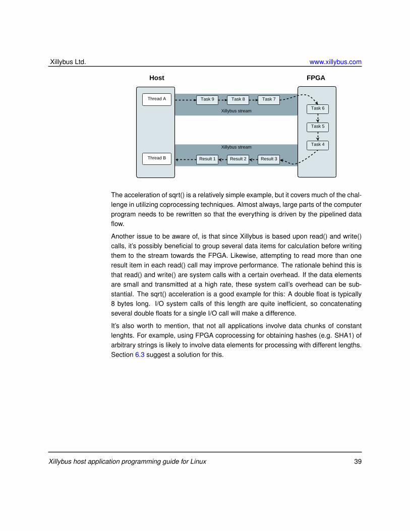
Returning to the example of sqrt(), the call to this functions is divided into two threads:The first thread sends the data for square root calculations to the hardware (or someother form of data structure representing the request for operation). The secondthread receives the results from the hardware and continues the processing from thatpoint in the algorithm.
This doesn’t seem to make much sense when looking at a single piece of data, butthe motivation for coprocessing implies that there are many data items to handle. Sothe first thread sends a flow of data for calculation, and the second thread receives aflow of results.
This pipelined technique minimizes the hardware’s latencies, since neither of thethreads is effectively waiting the latency time. Instead, the latency influences the min-imal gap of processing items between the both threads – but the throughput dependsonly on the processing capabilities of the two threads and the FPGA logic.
The following conceptual drawing summarizes the idea.
Xillybus host application programming guide for Linux 38
Xillybus Ltd. www.xillybus.com
Host
Task 9 Task 8 Task 7
Result 1 Result 2 Result 3
Task 6
Task 5
Task 4
FPGA
Thread A
Thread B
Xillybus stream
Xillybus stream
The acceleration of sqrt() is a relatively simple example, but it covers much of the chal-lenge in utilizing coprocessing techniques. Almost always, large parts of the computerprogram needs to be rewritten so that the everything is driven by the pipelined dataflow.
Another issue to be aware of, is that since Xillybus is based upon read() and write()calls, it’s possibly beneficial to group several data items for calculation before writingthem to the stream towards the FPGA. Likewise, attempting to read more than oneresult item in each read() call may improve performance. The rationale behind this isthat read() and write() are system calls with a certain overhead. If the data elementsare small and transmitted at a high rate, these system call’s overhead can be sub-stantial. The sqrt() acceleration is a good example for this: A double float is typically8 bytes long. I/O system calls of this length are quite inefficient, so concatenatingseveral double floats for a single I/O call will make a difference.
It’s also worth to mention, that not all applications involve data chunks of constantlenghts. For example, using FPGA coprocessing for obtaining hashes (e.g. SHA1) ofarbitrary strings is likely to involve data elements for processing with different lengths.Section 6.3 suggest a solution for this.
Xillybus host application programming guide for Linux 39
Xillybus Ltd. www.xillybus.com
AInternals: How streams are implemented
A.1 Introduction
Even though using Xillybus doesn’t require any understanding of its implementationdetails, some designers prefer knowing what happens under the hood, whether forcuriosity or for verifying the eligibility of a certain solution.
This section outlines the main techniques implemented for creating continuous streamsbased upon DMA buffers. The goal of this design is to make the underlying bufferstransparent to the user, and to a large extent they are. Please keep this in mind whengoing down to the technical details below, as they are very likely to be unnecessaryfor using Xillybus. This part is more about how it works, and less about things the userneeds to know.
There are two main sections below, one for the upstream flow, and one for the down-stream. As similar techniques are employed in both directions, much of one section isa repetition of the other.
For the sake of simplicity, the descriptions focus on asynchronous streams, exceptwhere comments on synchronous streams are given explicitly. The end-of-file signalas well as the option for non-blocking I/O are not covered either.
A.2 “Classic” DMA vs. Xillybus
Traditionally, data transport between hardware and software takes the form of a num-ber of buffers with a fixed size. The data is organized into buffers with a fixed length,but may or may not be filled completely. Each time a buffer is ready, some sort ofsignal is sent to the other side. For example, if the hardware has finished writing toa buffer, it may send an interrupt to the processor to inform the software that data
Xillybus host application programming guide for Linux 40

Xillybus Ltd. www.xillybus.com
is ready for processing. The software consumes the data, and informs the hardwarethat the buffer can be written to again, typically by writing to some memory-mappedregister. Typically, both the sides access the buffers in a round-robin manner.
Xillybus presents a continuous stream transport to the user interface, both on theFPGA and the software side. Under the hood, Xillybus uses the traditional round-robin paradigm with a set of DMA buffers.
However the techniques described below are employed to create an illusion of acontinuous stream, so that the user can ignore the existence of the underlying datatransport. In particular, even if the application consists of sending data in fixed-sizedchunks, there is no need to match the DMA buffers’ size to the application data, asexplained below.
A.3 FPGA to host (upstream)
A.3.1 Overview
The figure below depicts the flow in the FPGA to host (upstream) direction. Theshaded ares represent unconsumed data in the respective storage elements.
In this example, four DMA buffers are shown, even though the number can be config-ured in the IP Core Factory.
Leg #1 Leg #2 Leg #3
User applicationlogic
Xillybus IP Core +bus master interface
Xillybus host driver(software)
FPGAFIFO
DMAbuffers
User applicationbuffer
The data flows towards the host in three legs, as detailed next.
Xillybus host application programming guide for Linux 41

Xillybus Ltd. www.xillybus.com
A.3.2 Leg #1: Application logic to intermediate FIFO
The user application logic in the FPGA pushes data elements into the FIFO connectingbetween the user application logic and the Xillybus IP core. There is no requirementon when or how much data is pushed, except respecting the FIFO’s “full” signal toavoid overflow.
A.3.3 Leg #2: Intermediate FIFO to DMA buffer
In this leg, the Xillybus IP core copies the data from the FIFO to a DMA buffer inthe host’s RAM space. To accomplish this, the core uses some bus master inter-face (PCIe, AXI4 etc) to write data directly to the host’s memory, without the host’sprocessor’s intervention.
A pool of DMA buffers is allocated in the host’s RAM memory. The lifecycle of eachDMA buffer is like in many similar settings: In the beginning, all DMA buffers are emptyand conceptually belong to the hardware. The hardware writes data to the buffers ina round-robin manner: When it has finished writing to a certain buffer, it informs thehost that the buffer is ready for use (the buffer is “handed over to the host”), after whichit continues to write on the following buffer. The host may then consume the data inthe buffer handed over to it, after which it informs the hardware that the buffer can bewritten to again (the host “returns the buffer to the hardware”).
Leg #2’s data flow is controlled by the FIFO’s “empty” signal and by the availabilityof space in the pool of DMA buffers: When the Xillybus IP core senses a deassertedFIFO’s “empty” signal, and there’s is space left in some DMA buffer, it fetches datafrom the FIFO and writes it into a DMA buffer. When the FIFO becomes empty again,or there is no space in any DMA buffer, the IP core’s internal state machine stopsfetching data momentarily, and then continues from where it left off in the DMA buffer.
While the data flow is stalled, the IP core might be busy with other activities, for ex-ample copying data on some other stream’s behalf (i.e. draining another intermediateFIFO). As a result, there might be a random delay between the deassertion of the“empty” signal by the FIFO and the resumption of fetching data from it. This delayvaries, but the overall design guarantees that a FIFO of 512 words will not overflow(as long as the average rate is within limit).
Each DMA buffer may be filled completely before handing it over to the host, or maybe submitted to the host partially filled. The conditions for handing over a partiallyfilled buffer are detailed later (section A.3.5), as they require some understanding ofthe software’s behavior.
Xillybus host application programming guide for Linux 42

Xillybus Ltd. www.xillybus.com
The case of synchronous streams is quite similar, except that the Xillybus IP corewaits for an explicit request for a certain amount of data before fetching data from theintermediate FIFO.
A.3.4 Leg #3: DMA buffer to user software application
This leg is implemented on Xillybus’ driver on the host by responding to read() systemcalls (or the counterpart IRPs on Windows). According to the well-established API,the read() call request includes a buffer that is supplied by the user application, as wellas the size of the buffer, which is also the maximal number of bytes to read. The callmay return after reading the maximal number of bytes (complete fulfillment) or less.
The driver starts by checking the DMA buffers that are handed over to it, determiningwhether there is enough unconsumed data in the DMA buffers for a complete fulfill-ment, and if so, it copies the data to the user buffer, possibly returning DMA buffers tothe hardware, and returns.
Otherwise, the API for a read() call allows the driver to either return with less thanthe number of requested bytes, or wait (sleep) for any period of time. The driver isdesigned not to return too often with little data (which may cause a lot of read() callswith little data each, hence wasting CPU cycles), but also avoid unnecessary latency.The dilemma is what to do if there is less data in the DMA buffer(s) than required bythe read() call: To return with a partial fulfillment or wait (and how much to wait).
The chosen strategy is to wait for up to 10 ms for more data, and then return withwhatever was available (or wait possibly forever if no data is available, per API). Thisresults in a fairly responsive return time, but limits the overhead to 100 read() calls persecond, if the read() caller requests more than the data available all the time.
This is not to say that there is necessarily a 10 ms latency on read() calls: If the userspace application knows in advance how many bytes should be ready, it may requestno more than that number, and ensure a latency measured in microseconds.
There is however a tricky part: The host knows about the DMA buffers that havebeen handed over to it, but there may be a partially filled DMA buffer, which the hostisn’t aware of. So it might be, that there actually is enough data to fulfill a read() callcompletely, if the partially filled DMA buffer is counted in.
In order to handle this case properly, the driver checks whether the missing numberof bytes would fit into a partially filled buffer. If this is indeed the case, it informsthe hardware how many data elements would be enough. This gives the hardwarea chance to send a partially filled buffer, if it indeed allows completing the read() call
Xillybus host application programming guide for Linux 43

Xillybus Ltd. www.xillybus.com
entirely. The driver then starts the 10 ms wait.
If and when the partially filled buffer reaches the necessary amount (possibly rightaway), the hardware hands it over to the host, which then completes the read() callimmediately.
When the 10 ms period is over, the driver returns with as much data it has available. Ifthere is no data at all, the driver sends a request to the hardware to pass any partiallyfilled buffer it has. The purpose is to return as soon as there is any data, since the 10ms period is already over.
In all situations, when a DMA buffer has been consumed completely, the driver returnsit to the hardware (i.e. informs the hardware so it can be written to again).
A few words on synchronous streams: The flow is the same in principle, except thatdata is never available in the DMA buffers when the read() call is invoked, since thehardware isn’t allowed to copy data from the FPGA’s FIFO unless instructed to. Ac-cordingly, the read() call for synchronous streams involves informing the hardware onthe amount of data it should copy. The waiting mechanism remains the same: First10 ms, and then require any partially filled buffer.
A.3.5 Conditions for handing over partially filled buffers
The cases for handing over partially filled buffers can be deduced from the above, andare listed here for convenience.
The general rule is that a partial buffer is handed over to the host if the hardware hasbeen informed that such early submission will result in an immediate return of theread() call, which happens in either of three conditions:
• The host is currently handling a read() call, which will be fulfilled completelywhen the current partially filled buffer is handed over.
• A read() call stands at zero bytes, and has reached the time limit (typically 10ms).
• On synchronous streams only: When the hardware has completed fetching theamount requested by the host.
Note that the FIFO becoming empty is not a reason for a DMA buffer submission byitself.
Xillybus host application programming guide for Linux 44

Xillybus Ltd. www.xillybus.com
A.3.6 Examples
Let’s consider the following simple case of an 8-bit asynchronous stream. Supposethat a stream starts from fresh, after which the FIFO is filled with a single element(that is, one byte). The application program on the host then calls read() requestingone byte. This is a possible chain of events:
• The Xillybus IP core detects the low “empty” signal, and hence fetches a singlebyte from the FIFO, after which it becomes empty again.
• The byte is written, with DMA, to the first position in the DMA buffer. The hostisn’t notified, as the buffer isn’t (nearly) full.
• A read() call is invoked on the host, requesting one byte.
• The driver has no DMA buffer to take data from: The only DMA buffer containingdata (one byte) is only known to the hardware.
• The driver detects that the amount of data it needs is less than a DMA buffer’ssize, and therefore tells the hardware to hand over a partially filled buffer, if ithas at least one byte.
• The driver starts a 10 ms sleep, waiting for something to happen.
• The hardware responds immediately with handing over the partially filled bufferto the host.
• The driver wakes immediately, copies the one byte requested into the read() callbuffer, and returns.
This simple example demonstrates how a read() call returns virtually immediately,even though the data’s size was significantly smaller than the DMA buffer.
Let’s look at the example again, with one small difference: The read() call requeststwo bytes, even though only one is written to the FIFO. The sequence is as follows.
• The Xillybus IP core detects the low “empty” signal, and hence fetches a singlebyte from the FIFO, after which it becomes empty again.
• The byte is written, with DMA, to the first position in the DMA buffer. The hostisn’t notified, as the buffer isn’t (nearly) full.
• A read() call is invoked on the host, requested two bytes.
Xillybus host application programming guide for Linux 45
Xillybus Ltd. www.xillybus.com
• The driver has no DMA buffer to take data from: The only DMA buffer containingdata (one byte) is only known to the hardware.
• The driver detects that the amount of data it needs is less than a DMA buffer’ssize, and therefore tells the hardware to hand over a partially filled buffer, if ithas at least two bytes.
• The driver starts a 10 ms sleep, waiting for something to happen.
• The hardware does nothing, as it has only one byte in the DMA buffer, but twowere requested.
• The driver wakes after 10 ms, having nothing. It sends a request to the hardwareto hand over a partially filled buffer as soon as possible, unless it’s empty.
• The hardware responds immediately with handing over the partially filled bufferto the host.
• The driver wakes immediately, copies the one byte requested into the caller’sbuffer, and returns.
This second example shows the consequence of asking for two bytes when there wasactually only one: The call returns only after 10 ms, with the same one byte. Notehowever that the read() call is still fairly responsive.
A.3.7 Practical conclusions
• Even if the application-level data always consists of chunks of N bytes, thereis no reason to adapt the DMA buffer size in any way: The user applicationsoftware just needs to make sure to make the read() calls request data amountsexactly as needed, and the partial buffer mechanism will make sure that the callreturns when the data has been pushed into the FPGA’s FIFO, with a latencymeasured in microseconds.
• Even for continuous streams of data, latency can be reduced by making read()calls with small buffers, at the cost of additional operating system’s overhead.Regardless of the DMA buffers’ size, the latency depends only on the data rateand the byte count size given on the read() calls. Reducing the DMA buffer sizewon’t help, since the read() call will continue waiting up to 10 ms if it can’t fulfillthe read() call completely.
Xillybus host application programming guide for Linux 46
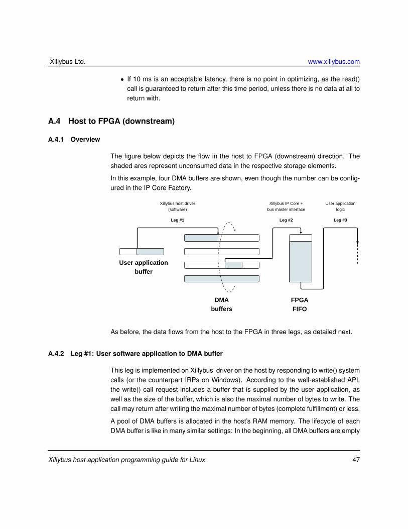
Xillybus Ltd. www.xillybus.com
• If 10 ms is an acceptable latency, there is no point in optimizing, as the read()call is guaranteed to return after this time period, unless there is no data at all toreturn with.
A.4 Host to FPGA (downstream)
A.4.1 Overview
The figure below depicts the flow in the host to FPGA (downstream) direction. Theshaded ares represent unconsumed data in the respective storage elements.
In this example, four DMA buffers are shown, even though the number can be config-ured in the IP Core Factory.
Leg #1 Leg #2 Leg #3
User applicationlogic
Xillybus IP Core +bus master interface
Xillybus host driver(software)
FPGAFIFO
DMAbuffers
User applicationbuffer
As before, the data flows from the host to the FPGA in three legs, as detailed next.
A.4.2 Leg #1: User software application to DMA buffer
This leg is implemented on Xillybus’ driver on the host by responding to write() systemcalls (or the counterpart IRPs on Windows). According to the well-established API,the write() call request includes a buffer that is supplied by the user application, aswell as the size of the buffer, which is also the maximal number of bytes to write. Thecall may return after writing the maximal number of bytes (complete fulfillment) or less.
A pool of DMA buffers is allocated in the host’s RAM memory. The lifecycle of eachDMA buffer is like in many similar settings: In the beginning, all DMA buffers are empty
Xillybus host application programming guide for Linux 47

Xillybus Ltd. www.xillybus.com
and conceptually belong to the host. The host writes data to the buffers in a round-robin manner: When it has finished writing to a certain buffer, it informs the hardwarethat the buffer is ready for use (the buffer is “handed over to the hardware”), afterwhich it continues to write on the following buffer. The hardware may then consumethe data in the buffer, after which it informs the host that the buffer can be written toagain (the host “returns the buffer to the host”).
Xillybus’ driver responds to write() calls by attempting to copy as much data as possi-ble into the DMA buffers. When any DMA buffer is filled completely, it’s handed overto the hardware, i.e. the host informs the hardware that the buffer can be consumed,and guarantees not to write to it again before the hardware returns the buffer to thehost.
If the driver managed to write at least one byte before running out of DMA bufferspace, the write() call returns with the number of bytes written. Otherwise is waits(”blocks” by sleeping), possibly indefinitely, until a DMA buffer is made available forwriting, at which it writes as much data as possible into the DMA buffer and returns.
Note that if a DMA buffer is partially filled, it’s not handed over to the hardware at theend of the write() call, so there may be data in one DMA buffer, which the hardwareisn’t aware of. A “flush” operation hands over a partially filled buffer, and it takes placein any of the following four cases:
• An explicit flush, caused by making a write() call with the required byte count setto zero. The write() call returns immediately (i.e. it doesn’t wait for the data tobe consumed by the FPGA).
• An automatic flush is initiated 10 ms after the last write() call.
• When the file is closed, a flush occurs, and the close() call waits for up to onesecond for the data to be consumed by the FPGA before returning.
• On synchronous streams, every call to write() ends with a flush(), which waitsindefinitely until the data is consumed by the FPGA.
Note that a zero-count write() call forces an explicit flush, making sure that all datathat has been written is available to the FPGA. However it doesn’t give the applicationsoftware an indication on when the data is consumed by the FPGA. If such synchro-nization is required, a synchronous stream should be applied.
Xillybus host application programming guide for Linux 48

Xillybus Ltd. www.xillybus.com
A.4.3 Leg #2: DMA buffer to Intermediate FIFO
In this leg, the Xillybus IP core copies the data from the DMA buffers in the host’s RAMspace to the FIFO in the FPGA. To accomplish this, the core uses some bus masterinterface (PCIe, AXI4 etc) to read data directly from the host’s memory, without thehost’s processor’s intervention.
Leg #2’s data flow is controlled by the FIFO’s “full” signal and by the availability ofdata in the pool of DMA buffers belonging to the FPGA: When the Xillybus IP coresenses a deasserted FIFO’s “full” signal, and there’s is data ready in some DMAbuffer, it fetches data from the DMA buffer and writes it into the FIFO. When the FIFObecomes full again, or the DMA buffers are exhausted, the IP core’s internal statemachine stops fetching data momentarily, and then continues from where it left off inthe DMA buffer pool.
While the data flow is stalled, the IP core might be busy with other activities, for exam-ple copying data on some other stream’s behalf (i.e.filling another intermediate FIFO).As a result, there might be a random delay between the deassertion of the “full” signalby the FIFO and the resumption of data copying. This delay varies, but the overalldesign guarantees that a FIFO of 512 words is deep enough.
The hardware is of course aware of partially filled DMA buffers, and keeps track ofhow much data each is filled with.
A.4.4 Leg #3: Intermediate FIFO to application logic
The user application logic in the FPGA fetches data elements from the FIFO connect-ing between the user application logic and the Xillybus IP core. There is no require-ment on when or how much data is fetched, except respecting the FIFO’s “empty”signal to avoid underflow.
A.4.5 An example
Let’s consider the following simple case of an 8-bit asynchronous stream. Supposethat a stream starts from fresh, after which the host application writes a single byte tothe device file.
• The driver’s write() call is invoked with a request to write one byte.
• As the stream is fresh, clearly there’s space in the DMA buffers. Hence thedriver copies the byte into the first DMA buffer and returns.
Xillybus host application programming guide for Linux 49

Xillybus Ltd. www.xillybus.com
• Nothing happens for 10 ms.
• The autoflush mechanism is triggered after 10 ms, causing the driver to handover the DMA buffer to the hardware with the information that it contains onebyte.
• The Xillybus IP core reads the byte from the DMA buffer and writes it into theintermediate FIFO.
• The application logic may read the byte from the FIFO at will.
A.4.6 Practical conclusions
• Even if the application-level data always consists of chunks of N bytes, thereis no reason to adapt the DMA buffer size in any way: The user applicationsoftware just needs to flush the data with a zero-count write at the end of eachchunk to obtain a latency measured in microseconds.
• Even for continuous streams of data, latency can be reduced by making write()calls with small buffers, followed by a zero-count write() flush, at the cost ofadditional operating system’s overhead. Regardless of the DMA buffers’ size,the latency depends only on the data rate and the byte count size given on thewrite() calls.
• It can make sense to reduce the DMA buffer size if it’s know in advance that aflush always occurs after a given chunk of data, and hence no DMA buffer isever filled beyond a certain level. However the only advantage of doing so issaving some RAM at the host, which is unlikely to be significant.
• If 10 ms is an acceptable latency, there is no point in optimizing, as the aut-oflushing mechanism kicks in after 10 ms of idling.
Xillybus host application programming guide for Linux 50