xml based schema definition for support of inter-organizational...
TRANSCRIPT

1
XML Based Schema Definition for Support of Inter-organizational Workflow
W.M.P. van der Aalst1,2 and Akhil Kumar1,3
1 College of Business and Administration, University of Colorado, Campus Box 419, Boulder, CO 80309-0419, USA.
2 Faculty of Technology and Management, Eindhoven University of Technology, PO Box 513, NL-5600 MB, Eindhoven, The Netherlands.
3 Database Systems Research Department, Bell Laboratories, 600 Mountain Avenue, Room 2A-406, Murray Hill, NJ 07974.
E-mail: [email protected],[email protected]
Abstract
The full potential of the web as a medium for electronic commerce can be realized only when multiple partners in a supply chain can route information among themselves in a seamless way. Commerce on the Internet is still far from being "friction-free" because business partners cannot exchange information about their business processes in an automated manner. In this paper, we propose the design for an eXchangeable Routing Language (XRL) using XML syntax. XML (eXtendible Markup Language) is a means for trading partners to exchange business data electronically. The novel contribution of our work is to show how XML can also be used to describe workflow process schemas to support flexible routing of documents in the Internet environment. The design of XRL is grounded in Petri nets, which is a well-known formalism. By using this formalism, it is possible to analyze correctness and performance of workflows described in XRL. Architectures to facilitate inter-operation through loose and tight integration are also discussed. Examples illustrate how this approach can be used for implementing inter-organizational electronic commerce applications. As a proof of concept we have also developed XRL/flower, a prototype implementation of a workflow management system based on XRL.
1. Introduction
With the rapid expansion seen in electronic commerce1, there is a major need for infrastructures and
frameworks that can be used to implement inter-organizational applications. In particular it is essential to
provide support for routing of documents across organizations in a standardized and yet flexible manner
to enable open electronic commerce [18,19,26,27,33,36,53]. Developing more homogeneous languages
for various electronic commerce activities [21] is one way to facilitate increased productivity and
interoperability. In this paper, we describe an architecture and a language called XRL (eXchangeable
Routing Language) that provide support for routing of workflow among trading partners for Internet-
based electronic commerce services.
1 In 1998, about $ 43 billion worth of business was done over the Web. This volume was projected to
increase to $1.3 Trillion by 2003.

2
Current workflow products are generally intra-organizational and based on centralized architectures.
Therefore, they typically lack scalability and are also not very useful for implementing inter-
organizational applications [1,4,5,6,36]. Moreover, these systems use propriety languages for specifying
workflow processes. Despite efforts by the Workflow Management Coalition (WfMC, [30]), a lingua
franca for workflow management is lacking. The Workflow Process Definition Language (WPDL) of the
WfMC has no formal semantics, i.e., the dynamics of many of its constructs are ill-defined, and most
systems only support a subset of WPDL. The standard proposed by the WfMC for interoperability among
different workflow systems (Wf-XML [50]) is based on WPDL and traditional centralized architectures.
Such an approach does not address some of the fundamental problems related to cross-organizational,
highly-dynamic workflows. The only way to support such workflows is for each organization to have a
common understanding for the workflow processes at hand. Therefore, we propose a new language which
enables the easy and unambiguous exchange of process information, i.e., a lingua franca for cross-
organizational workflow.
An inter-organizational workflow involves communication between two (or more) parties with different
information systems. Although various suppliers of products and services, such as Dell, Federal Express,
etc., already make order tracking information available on their web sites, the next level of customer
support will allow customers to perform more detailed order status inquiries, and to make changes
dynamically to their orders (e.g., "change the cd-rom in my laptop order to a DVD"). For instance, a
customer should be able to find out why his or her order is delayed, and what are possible alternatives for
expediting it (perhaps, the delayed component or feature is not so important and can be omitted, or a
substitute can be used, etc.). Process information is also very useful because it encapsulates the business
rules of an organization. For instance, one supplier may expect to receive payment after delivery, while
another may have the opposite policy. Therefore, a customer who deals with both suppliers, and does not
pay careful attention to these rules, may be held up waiting for the shipments to arrive not realizing that
the payment has not been made in one case. Currently, such misunderstandings are prevented by paying
careful attention to business rules of organizations, which are available in hardcopy form. Often
considerable manual interaction between personnel of the buyer and supplier organizations is required to
parse and understand these rules. This is time consuming and expensive, and incurs delays, especially in
setting up new arrangements between two partners. We anticipate that friction-less e-commerce will
only be possible if such arrangements can be established on the fly, in an automated manner. This
requires that each partner make its processes (at least, selectively) transparent to its other partners (e.g.,
the process schema would show whether payment occurs prior to, or after, delivery).
Inter-organizational workflows are problematic because the process information of each partner is hidden
from other partners, and there is no easy or common way of describing such information. While the

3
partners are able to exchange transactional data based on prior arrangements, through means such as EDI
(described shortly), it is not possible to exchange detailed process level information. Such information is
crucial for close interaction and cooperation to enable frictionless e-commerce.
XML and EDI are two technologies for data exchange. While EDI is a well-known standard for data
exchange, XML is not a standard in the same sense; instead, it has the capability to define the contents of
documents through a set of elements or tags. EDI is based on the notion of transaction sets, which are
standard, formatted documents such as a purchase order, delivery agreement, etc. Each transaction set
defines the precise structure of the corresponding document, and is used to exchange business information
between partners. XML, on the other hand, is designed to be "extendible" by allowing users to define
various entities on a form such as, name, address, price, quantity, etc. as tags or elements, thus creating
user-defined forms. The structure or schema of an XML document is described by its Document Type
Definition (DTD). When setting up a relationship through EDI or XML, business partners must still
agree before hand on the sequence in which these documents are exchanged, and what action a partner
must perform upon receiving a certain document. Partners must agree, for example, on how stock-outs
will be handled, who specifies delivery dates and what is done if a delivery date cannot be met, and what
is done if a trading partner specifies an improper product number or there is a disagreement on pricing.
This is essentially process information, which is not automated in current solutions. These issues are
typically agreed to outside of the electronic exchange and can cause significant problems if partners do
not agree to them in advance. Our proposal in this paper is an attempt to extend data exchange
technologies such as EDI and XML with the exchange of process information as well, by making inter-
organizational workflows explicit. This is the main motivation for developing XRL.
At the outset, it is important to clarify that XRL is not XML; rather, XRL uses XML syntax to define a
DTD, consisting of a set of elements or tags for describing workflow applications. It consists of routing
constructs that are used as building blocks to design routing schemas for inter-organizational applications.
It is described in XML syntax because XML parsers are easily available and XML is rapidly becoming an
international standard [15,39,52]. According to InformationWeek [24], a widely-read magazine, “As a
basis for universal data interchange among companies, XML has permeated every sector of business,
from aviation and accounting to weather and workflow.” Moreover, query languages for XML data (such
as Xpath) are also becoming available; thus, if a workflow is described in XML, it can be queried [16]. In
Section 7, we compare XRL with existing standards for workflow management (e.g. SWAP, JFLOW, and
Wf-XML), and electronic commerce solutions (e.g., ebXML, OBI, xCBL, RosettaNet, UDDI, and
OAGIS).
Four important features of XRL should be noted. One core feature of XRL is that it provides a mechanism
to describe processes at an instance level, i.e., an XRL routing schema describes the partial ordering of

4
tasks for one specific instance. Traditional workflow modeling languages describe processes at a class or
type level [20,25,30,44]. However, in the context of inter-organizational workflow, it is unrealistic to
assume that the different organizations share a common process model. Moreover, it should be possible to
modify and migrate instances (or parts of instances) from one organization to another without prior
agreement on the precise order in which tasks are executed. Therefore, while modeling at a schema level
is still possible, instance level modeling gives additional flexibility. A second important feature is that
XRL lends itself well to both distributed and asynchronous modes of operation. Section 3 will describe
a distributed architecture, which is more scalable and reliable than a centralized one [12]. Moreover, in
many real applications (e.g., in supply chain management [13,14,31]), asynchronous transmission of
messages can be more reliable and efficient than synchronous transmission. A third feature is that the
semantics of XRL are expressible in terms of Petri nets [7,11,17,41]. Such formal semantics allow for
powerful analysis techniques, an efficient and compact implementation, interfaces to many existing tools,
and, last but not least, an unambiguous understanding of XRL. As workflows get increasingly complex
the need for tools for analysis and formal verification of workflows will assume even greater importance.
A fourth important feature is the expressive power of the language, i.e., the ability to realize desirable
routing constructs in a succinct and direct manner. In our research on workflow patterns [9,10], we
compared the expressive power of many contemporary workflow management systems including COSA,
HP Changengine, Forté Conductor, I-Flow, InConcert, MQ Series Workflow, R/3 Workflow, Staffware,
Verve, and Visual WorkFlo using a set of workflow patterns (http://www.tm.tue.nl/it/research/patterns/).
Based on the workflow patterns supported by these systems and their relative use in practice, we carefully
selected the most relevant constructs for XRL. Note that the extendible nature of XRL allows for the
addition of new constructs by simply adding the construct to the XRL DTD (see Appendix 1) and
providing the corresponding Petri-net semantics (see Appendix 2).
A prototype workflow management system named XRL/flower has been developed as a proof of concept.
XRL/flower provides full support for the XRL language presented in this paper.
This paper is organized as follows. Section 2 provides background material related to workflow support
for electronic commerce. Section 3 gives an overview of the architecture based on the idea of routing
slips. Next, Section 4 describes the various constructs of the XRL routing language. Then, Section 5
shows how XRL can be mapped into Petri nets. Section 6 illustrates the language with real examples and
screenshots of our workflow management system XRL/flower. Finally, Section 7 discusses related work
and Section 8 concludes the paper.

5
2. Basic Background and Motivation
2.1. Why use XML and what is XML?
The Web has ushered an era of "any time, anywhere, any place" communication. Widely-accepted
standards, like HTML, are crucial to using the Web to its full potential. However, HTML is a visual
display and user interface standard. It allows a page to be created once and be displayed at different times
by anyone with a browser. Since browsers have become universal, millions of people world-wide can
have access to the same content within seconds of its creation.
Clearly, although visual and user interface standards are important, they are insufficient for representing
and managing data. Today, the Internet is primarily an access medium for text and pictures. There are no
standards for intelligent search, data exchange, adaptive presentation, and personalization. As a next step
what is required is a common way of representing data so that software can better search, move, display,
and manipulate information hidden in contextual obscurity. HTML cannot do this because it is a format
that describes how a Web page should look; it does not represent data. For example, HTML does not:
• provide a standard way for a customer to send an order to a supplier.
• specify a standard way for a doctor to send a prescription to a pharmacist.
• enable a company to publish a catalog of products and prices in a standard way that allows a
salesperson to work offline, show the catalog to clients, take orders, and upload those orders in a
standard format.
• describe an electronic payment in a form that any recipient can decode and process.
• provide a standard way to search law libraries for all litigation documents about a certain topic.
In short, while HTML provides rich facilities for display, it does not provide any standards-based way to
manage data. This is where XML serves a useful purpose. XML is a markup language that allows users
to define a set of tags, which describe the structure of a document [15,39,45,46]. For example, a user may
specify tags for NAME, AGE, DEPARTMENT, EMAIL, etc. This logical structure may be stored either
in the document file itself and/or in an associated file called the Document Type Definition (DTD) file
[15] or the XML Schema (XSD) file [52], which is linked to the document file. This facilitates more
precise declaration of content and more meaningful search results across multiple platforms. In addition,
XML will enable a new generation of customized Web-based data manipulation applications.
XML provides a structured representation of data that can be implemented broadly and is easy to deploy.
XML is a subset of SGML (Standard Generalized Markup Language), modified and optimized for
delivery over the Web. This standard has been defined by the World Wide Web Consortium (W3C) [15].
6
XML, which provides a data standard that can encode the content, semantics, and schemata for a wide
variety of cases, ranging from simple to complex, can be used to mark up a purchase order, an invoice, a
payment advice, a doctor’s prescription, information about people and organizations, etc. Thus, XML
ensures that structured data will be uniform and understandable across a variety of applications, vendors
and customers. This resulting interoperability is kick-starting a new generation of business and electronic-
commerce Web applications.
XML is valuable to the Internet, as well as to large corporate Intranet environments, because it provides
interoperability using a flexible, open, standards-based format, with new ways of accessing legacy
databases and delivering data to Web clients. Applications can be built more quickly, are easier to
maintain, and can easily provide multiple views on the structured data. XML has already opened up a
wide variety of new uses, all based on a standard representation for moving structured data around the
Web as easily as we move HTML pages today. While XML can help in exchange of semantic
information, it still lacks routing information. Such information is critical to enable proper routing of a
document within an organization and across organizations. Our proposal in this paper is to further use
XML for not just data exchange but also for exchange of routing information. We view this as a natural
evolution of XML, which will expand the Internet in much the same way that the HTML standard for
displaying content did a few years ago. Therefore, in a simplistic way, one may think in terms of three
evolutionary stages of Web development:
Stage 1: HTML standard for visual display and user interface
Stage 2: XML standard for data exchange within and among organizations.
Stage 3: Add workflow features with routing semantics and enable interoperability.
Therefore, while stage 2 is an important step towards data integration, our proposal aims towards tighter
interoperability. In the next subsection we provide background on features of workflow systems,
application areas where workflow support is required and the role XML can play.
2.2. Workflows in XML
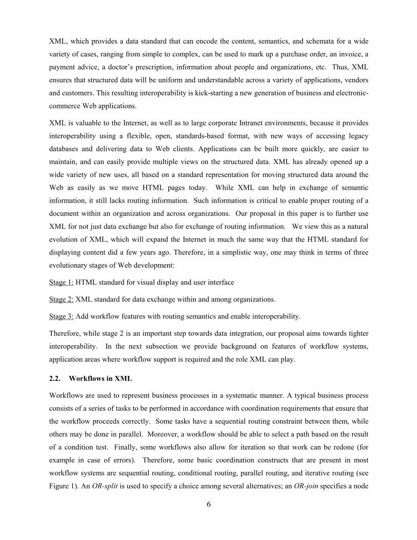
Workflows are used to represent business processes in a systematic manner. A typical business process
consists of a series of tasks to be performed in accordance with coordination requirements that ensure that
the workflow proceeds correctly. Some tasks have a sequential routing constraint between them, while
others may be done in parallel. Moreover, a workflow should be able to select a path based on the result
of a condition test. Finally, some workflows also allow for iteration so that work can be redone (for
example in case of errors). Therefore, some basic coordination constructs that are present in most
workflow systems are sequential routing, conditional routing, parallel routing, and iterative routing (see
Figure 1). An OR-split is used to specify a choice among several alternatives; an OR-join specifies a node
7
where several alternative paths in the workflow process definition come together. The routing decisions in
OR-splits are often based on data, such as whether a task was performed correctly, the age of a customer,
or the contents of a letter from the customer. On the other hand, an AND-split and AND-join can be used
to specify the start and end of multiple parallel paths.
sequential routing A B C D
A
B
C
D conditional routing OR-split OR-join
A
B
C
D parallel routing AND-split AND-join
iterative routing A B C D
OR-split OR-join
Figure 1: Four basic routing types using AND/OR and split/join building blocks
Clearly any workflow language should support the four constructs shown in Figure 1. However, as shown
in [9,10] these basic constructs are inadequate. More advanced constructs are needed to easily model and
enact complex real-life workflows. In our research on workflow patterns [9,10], we compared the
expressive power of some of the leading workflow management systems on the market. Using a set of
workflow patterns we evaluated COSA (Thiel Logistik AG/Ley GmbH/COSA Solutions BV), HP
Changengine (Hewlett-Packard), Forté Conductor (Forte/SUN), I-Flow (Fujitsu), InConcert (TIBCO),
MQ Series Workflow (IBM), R/3 Workflow (SAP AG), Staffware (Staffware PLC), Verve (Verve Inc.),
Visual WorkFlo (FileNET), and some research prototypes (cf. http://www.tm.tue.nl/it/research/patterns/
[10]). Based on the workflow patterns supported by these systems and their relative use in practice, we
carefully selected the most relevant constructs for XRL.
Petri nets allow for the modeling of the four constructs shown in Figure 1 and have been proposed for
modeling workflow process definitions long before the term “workflow management” was coined (cf.

8
[17] for some historical remarks). However, we do not propose Petri nets as a modeling language. Instead
we propose high-level constructs inspired by our research on workflow patterns [9,10]. Nevertheless, we
provide a mapping from XRL to Petri nets. As a result, we can use the strong theoretical results from Petri
nets, apply various analysis techniques, and use an efficient workflow engine based on Petri nets. For a
more elaborate introduction to Petri nets and the application of Petri nets to workflow management, we
refer the reader to [7,11,17,25,41].
Workflow management systems such as COSA, HP Changengine, Forté Conductor, I-Flow, InConcert,
MQ Series Workflow, R/3 Workflow, Staffware, Verve, and Visual WorkFlo are not interoperable and
they all use proprietary formats to represent workflow schemas. XML, which is rapidly becoming
universal on the Web, can serve as a common language for unifying disparate workflows from different
vendors and reconcile them.
Three broad application areas in which support for workflows and inter-operability is important are:
• Enterprise resource planning (ERP) applications (e.g., from Oracle, PeopleSoft, SAP, etc.)
• Customer relationship management (CRM) applications (e.g., from Siebel, Clarify, etc.)
• Supply chain management (SCM) applications (e.g., from i2, Manugistics, etc.)
In all three areas, vendors are working hard to workflow enable their products. The kinds of problems
that arise in supply chain management are especially suitable for use of workflow technology. The
common aspects of these problems are multiple business partners, flow of information through exchange
of documents, and need for complex coordination using some of the constructs discussed above. In the
next subsection, we describe an example problem that exhibits the characteristics of supply chain
problems. Later we will return to this problem to show how it can be solved using our framework.
2.3. Workflow in Mail Order Processing
In this subsection, we describe an example of a workflow related to electronic commerce in some detail.
This example will be used later to illustrate our techniques. The following description accompanies
Figure 2, where the numbers denote the approximate sequence in which various steps are performed.
Suppose that a customer places an order for three books with Amazon.com. Since these three books come
from different publishers, Amazon in turn places three different orders (one for each book) with the
publishers. Then Amazon must wait for confirmations from the publishers about whether they can deliver
the books within the deadline specified by the customer. Moreover, the customer may also have stated
conditions like "all or nothing" or "at least two out of three" etc. If the conditions stipulated by the
customer cannot be met, then he/she must be notified accordingly. If they can be met, then Amazon must
confirm the order with the publishers involved, and next find a shipper. The shipper coordinates the
receipt of and onward delivery of the three different shipments from the publishers. Here again, several

9
situations can arise. The books are likely to arrive separately, possibly even on different days, and the
shipper must determine whether to batch the order into one shipment or in multiple shipments as they
arrive. (It is interesting to note that in general, there are 12 −n combinations of partial shipments.)
Finally, billing must be handled. Since customers are normally billed upon shipment, the shipper must
notify Amazon immediately after the shipment is sent, and Amazon or its billing company will bill the
customer at this point. Again, billing can also be either batched, or done singly for each partial order that
is shipped.
This simple example illustrates the complexity that can arise in performing a simple workflow over the
Internet. There are seven parties who have to coordinate among themselves in order to successfully
complete the order. Other complications that can arise are:
• The customer may cancel or change the order before it is shipped.
• A publisher may not be able to ship the book as committed.
• The shipper may not be able to deliver on time.
In all these scenarios there is need for additional coordination, and, possibly negotiation.
Customer (Joe or Jane)
Amazon Billing
Publisher 1 Publisher 3 Publisher2
Shipping Co. (1)
(8)
(7) (6) (5)
(4) (3) (2)
Figure 2: A mail order example.
3. Architecture
Our general approach is based on the metaphor of a routing slip that defines the routing schema. A
routing slip is a simple sequence of roles or users who must review the documents in a certain sequence.
One or more documents can be attached to, modified, and detached from the routing slip by various
workers. An owner creates the routing slip and defines the routing patterns in terms of various constructs,
to be discussed in the next section. Each slip has a unique ID that can be used to trace the routing slip.

10
XRL extends the routing slip metaphor, as we will see at length in Section 4. However, this section will
focus mainly on overall architectural issues.
Figure 3 shows the WfMC (Workflow Management Coalition, [30]) reference architecture which is
centered around the workflow engine. The various interfaces shown here have been partly specified by
WfMC. Unfortunately, precise semantics of these interface specifications are not given and most vendors
have generated their own definitions. The client applications can access the workflow engine over a
network. The process definition tools allow the process to be specified. The administration tools are for
managing the workflow engine. There is also support for additional services. Very recently, the WfMC
has issued a specification for Interface 4 of Figure 3 based on XML [50]. This specification is named Wf-
XML and models the data transfer requirements among different workflow engines in XML. It allows
process status and results to be exchanged among multiple engines. Unfortunately, it does not go into the
specifics of routing. In Section 7, we shall compare XRL with Wf-XML further.
Process Definition Tools
Administration & Monitoring
Tools
Interface 1
Interface 4Interface 5
Workflow Enactment Service
Workflow API and Interchange formats
Other WorkflowEnactment Service(s)
WorkflowClient
Applications
Interface 3Interface 2
WorkflowEngine(s) Workflow
Engine(s)
InvokedApplications
Figure 3: WfMC reference model architecture (©WfMC [30]).
Figure 4 shows our own architecture of the workflow engine. Our workflow management system
XRL/flower uses this architecture. The routing schema in XRL is received at a node through email. It is
parsed using a standard XML parser and stored as an XML data structure. The core of the engine reads
this parsed structure and creates a Petri-net representation. This representation is used by the engine to
determine the next step(s) to be performed and then to present them to the user through a user interface.
The user then enters the action taken by him/her to complete the step and notifies the workflow engine
which determines the next step(s). When all the steps at this node are completed, the workflow engine
writes out the revised XRL data structure and sends it to the next node in the workflow.

11
Parse XRL
User interface for system
administrator
Write XRL
Email, XRL
Convert XRL into a Petri net and store in
relational tables
Engine
E A
E: Enabled steps A: Action
Send E-mail with a URL to next worker
Task execution in browser by (next) worker
Email, XRL
Tight integration
Loose integration
Figure 4: Architecture of XRL/flower.
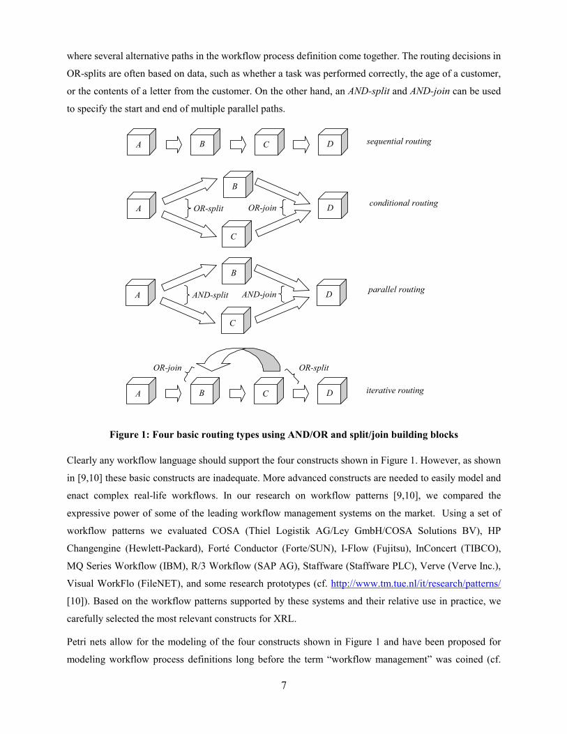
We envisage two modes of operation with our architecture as illustrated in Figure 5. The step numbers in
the figure correspond to tasks of a workflow, such as a customer placing an order, Amazon checking
availability, the publisher confirming the order, the publisher giving the book to a shipper, billing, etc. In
the first mode (see Figure 5 (a)) a main workflow (Workflow 1 in Figure 5) performs various steps while
keeping overall control of the the workflow instance. Various steps within this workflow involve
participation of other entities and workflows; however, overall control is retained at one workflow engine.
For instance, a supplier may be asked to access an electronic form at a URL, enter information into it, and
press a submit button to complete this step. Upon completion of this step, the main workflow continues
further based on the information provided by the supplier. This mode of operation results in loose
integration between the two workflows. In the second scenario, one workflow may transfer a running
instance to another workflow and thus completely relinquish its control over it. This situation is
illustrated in Figure 5 (b). Here, Workflow 1 “ships” the XRL file and any associated data files to
Workflow 2 (by mail or ftp, perhaps). (Note that the XRL file also contains markers to record the current
state of a running instance as we will see later.) Upon receiving these documents, Workflow 2 will parse
the XRL file and perform the steps that it is required to do. After performing the steps, Workflow 2 will
rewrite the new XRL file to reflect the new state of the workflow instance. Finally, it will send the
revised XRL file and any modified or newly created data files back to Workflow 1, where the instance
will resume. This produces tight integration between the two workflows.
12
Workflow 1 (e.g. Customer) Workflow 2
(e.g. Supplier) Step 1 Step 2 Step 3
Step 41 Step 43
Step 5 Step 6
XRL file + data
Step 42 XRL file + data
Workflow 1 (e.g. Customer) Workflow 2
(e.g. Supplier) Step 1 Step 2 Step 3 Step 4 Step 5 Step 6
URL
(a) loose integration (b) tight integration
Figure 5: Two modes of inter-workflow operation.
The XRL routing slip can be created and modified using a GUI editor. In the next section we turn to the
description of the routing schema. Later, in Section 6, we return to our prototype workflow management
system XRL/flower and provide some screenshots also.
4. Defining a Routing Schema in XML
As discussed earlier, XML (eXtensible Markup Language) is very fast becoming a de facto standard for
exchange of information among trading partners. It offers syntax, semantics, and presentation support.
Therefore, XML was chosen as the basis for our routing language called XRL (eXchangeable Routing
Language). In this section we describe various routing constructs that serve as building blocks. These
constructs are the ones that arise most commonly in real-world workflows. Some of the accompanying
examples will serve to motivate the need for them. Later, we show that these constructs can be used to
provide support for designing and implementing complex routing scenarios. Moreover, we provide a
Document Type Definition (DTD) to completely specify the XRL syntax (cf. Section 4.8).
4.1. Route
A routing slip or schema must start with a <route> start-tag and end with a </route> end-tag. The
route element has a reference attribute to uniquely identify the routing slip. A route consists of a routing
element which is described next. The <route> tag has the following attributes associated with it:
name: Name of the routing slip
created by: Creator of the routing slip
date: Creation data
4.2. Routing Element
A routing element is an important building block of XRL and it can be any one of the following:

13
1. Task: This is a step to be performed.
2. Sequence: A set of tasks to be done in a specific order forms a sequence.
3. Any_sequence: A set of tasks to be done in any order forms an any_sequence.
4. Choice: Any one task out of a set of tasks is called a choice.
5. Condition: Test a condition and determine next step based on the result of the test.
6. Parallel_sync: Create multiple parallel routing elements and later join them.
7. Parallel_no_sync: Create multiple parallel routing elements (which do not have to join).
8. Parallel_part_sync: Create multiple parallel routing elements, some of which must join.
9. Wait_all: Insert a wait step to wait for the completion of a group of events.
10. Wait_any: Insert a wait step to wait for the completion of any one of a group of events.
11. While_do: Enable repetition of a task while a condition is true.
12. Stop: End the execution of this particular path of the workflow instance.
13. Terminate: End this workflow instance.
Note that the selection of these constructs is based on a detailed analysis of workflow patterns needed in
practice and the features offered by the leading workflow management systems [9,10].
4.3. Task
A task is a generic term for a step or action in the workflow. The following attributes are associated with
a task:
name: name of the task address: URL of the task or an email address role: information about the actor (person or organization) executing the task doc_read: documents required by the task that are read-only doc_update: documents that can be updated doc_create: documents that are to be created by the task domain: Internet domain within which the task is performed result: result of the task as a string value status: status of task (ready|running|enabled|disabled|aborted|null) start_time: time at which the task was started end_time: time at which task was completed notify: email addresses of parties to be notified on task completion.
14
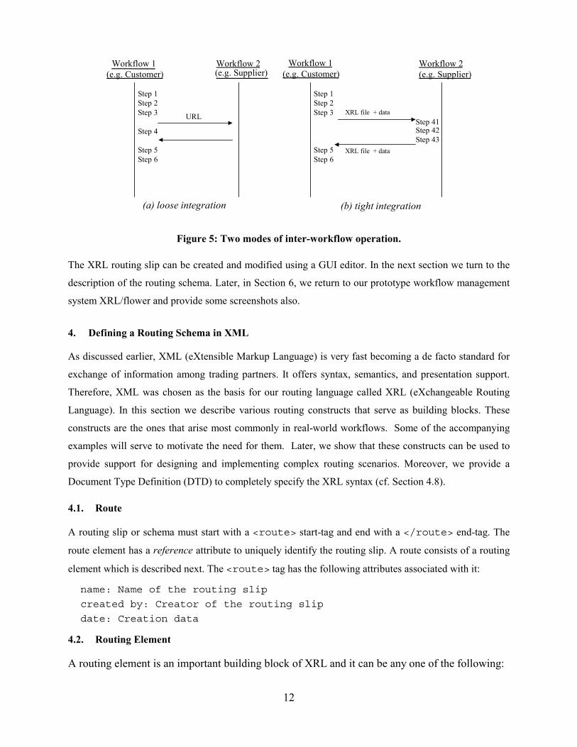
A task element must have a unique name attribute which is an id, and an address that is a URL (say,
an HTML page or ASP or JSP page) or an email address. Several other attributes can be associated with a
task. An example of a task specification is as follows:
<task name="task1" address="www.order.xyz.com" start_time = "01Oct99;9:30AM" end_time = "">
</task>
The status attribute is initially null and can take one of the values from among the ones listed above. The
start_time and end_time attributes correspond to the start and end times of the task and can be
used to determine how long it lasted. Another example of a task element is:
<task name="task3" address = "[email protected]" result = " " doc_read ="doc1 doc2" start_time = "01Oct99;9:30AM" end_time = "">
</task>
Here the address is an email address of the worker who will perform task3. Moreover, it is possible to
specify documents to be attached using the doc_read attribute. Thus, the workflow engine will send an
email to [email protected] and attach doc1 and doc2 to it.
4.4. Sequence
A sequence represents the simplest routing pattern. It is a way to group together multiple steps to be
done in a certain order. Here is an example of how a sequential workflow can be specified using XRL.
<sequence> <task name = "task1" address = "[email protected]" doc_read = "doc1,doc2" > </task> <task name = "task2" address = "[email protected]" doc_read = "doc3,doc4" > </task> <task name = "task3" address = "[email protected]" doc_read = "doc5,doc6" > </task> <task name = "task4" address = "[email protected]" > </task>
</sequence> Thus, a sequence is a logical way of grouping several sequential tasks.
4.5. Parallel Constructs
There are three related types of parallel constructs: parallel_sync, parallel_part_sync,
and parallel_no_sync.

15
In all these constructs, the common aspect is that they allow sub-workflows to be created which can
proceed independently. The parallel_sync element corresponds to the traditional notion of parallel
routing: First a number of parallel branches is activated, then the parallel branches are executed
independently, and finally the completed branches are synchronized (see AND-split and AND-join of
Figure 1). In the parallel_part_sync only some of the sub-workflows need to be combined, as
specified by the attribute number. Finally, in a parallel_no_sync element, the sub-workflows are
not synchronized and processing is resumed after all sub-workflows are initiated.
Next we discuss some examples of these three constructs. In the first example below, three vice-
presidents must approve an invoice before it can be paid. The approvals can be done in parallel, but
subsequent steps of the workflow cannot proceed without receiving the approvals.
<parallel_sync> <task name = "vp1" address = "[email protected]" doc_read = "invoice.doc"/> <task name = "vp2" address = "[email protected]" doc_read = "invoice.doc"/> <task name = "vp3" address = "[email protected]" doc_read = "invoice.doc"/> </parallel_sync> Next, we consider a modified situation where all the tasks do not need to synchronize. In this case we
would express the requirements as follows using the parallel_part_sync construct.
<parallel_part_sync number = 2> <sequence> <task name = "send-to-vp1" address = "[email protected]" doc_read = "invoice.doc"/> <task name = "vp1" address = "[email protected]" doc_update = "invoice.doc"/> </sequence> <sequence> <task name = "send-to-vp2" address = "[email protected]" doc_read = "invoice.doc"/> <task name = "vp2" address = "[email protected]" doc_update = "invoice.doc"/> </sequence> <sequence>
<task name = "send-to-vp3" address = "[email protected]" doc_read = "invoice.doc"/>
<task name = "vp3" address = "[email protected]" doc_update = "invoice.doc"/> </sequence> </parallel_part_sync>
In the modified description now, only two of three vice-presidents (any two) are required to approve the
invoice. As soon as any two of them have done so, the workflow may proceed to the next stage. Finally,

16
the third option (parallel_no_sync) for parallelism in the workflow design is to not require any
synchronization at all. This would effectively mean that as soon as the three approval tasks are assigned,
the workflow may continue to other tasks. In this case some other mechanism may be employed to check
later that the approvals have indeed been done. For instance, while the approvals of an invoice are in
progress, other tasks such as printing the check may be performed. However, the mailing of the check can
be delayed until the approvals are obtained. For brevity, we omit the full XRL syntax for this scenario.
4.6. Condition checking and Looping
The condition element is used to check a general condition statement and direct the workflow based on a
Boolean result. The condition element has an attribute called condition that describes the
condition to be tested. The structure is as follows:
<condition condition = "result = ‘ok’"> <true> <task name = "send_confirmation" address="www.xyz.com/confirm"/> </true> <false> <task name = "notify_customer" address="www.xyz.com/notify"/> </false> </condition>
As shown above, the true and false elements are associated in conjunction with the condition
element, and at least one of them should be present.
The while_do construct allows repetition of workflow routing elements and steps. It has a
condition attribute that describes the condition (as in the condition element), and the elements
enclosed within the while_do construct are executed until the condition evaluates to true.
4.7. Wait, Events, Timeouts, Terminate, Stop and State Elements
These elements of XRL are covered briefly next. The syntax for them is described in the DTD in
Appendix 1. There are two types of wait elements: wait_any and wait_all. Each element encloses
one or more combinations of event references and timeouts. A wait_any element will be considered
complete when any one of the events or timeouts it contains is done. On the other hand, wait_all
requires the completion of all of the events or one of the timeouts it encloses.
An event can be optionally associated with a task by including one or more event elements within a task
element. It is possible to wait for the occurrence of this event within a wait element by specifying an
event reference element. For example,
<task name = approve>

17
<event name = e1 /> </task>
This construct specifies an approve task and associates an event e1 with it such that upon completion of
the task, event e1 will "fire" (i.e., be triggered). Now, consider the following XML code, which, perhaps,
appears later in the same workflow instance:
<wait_all> <event_ref name = e1/> </wait_all> This is a way to specify that the workflow instance must wait until the approve task is completed, i.e.,
events can be used as milestones. Another way to use the wait constructs is in conjunction with timers.
There is a timeout element with attributes time and type. The time attribute specifies a string value of
time, while the type attribute helps to interpret the string value, either as an absolute time (January
25, 9 AM), relative time to the current time (i.e., like a regular timer) or s_relative, i.e., a time
which is relative to the start of the instance.
The stop element is used to end a sub-workflow of the workflow instance. The terminate element on
the other hand terminates the entire instance that includes all its paths that may be executing separately.
Both stop and terminate do not have any attributes and are typically used within a condition
element. For example, if a condition in one of several parallel branches evaluates to false, the entire
workflow instance is terminated.
The state element is required to write out the state of the workflow at any point. This is a useful feature
to make a record of the exact state of the workflow instance in the XRL routing slip. The location of the
state element determines the progress of one path of the workflow instance. In a purely sequential
process there will be only one state element. In presence of parallelism, there can be multiple state
elements, each indicating the state of one parallel branch. To avoid confusion and maintain readability,
state elements are only allowed inside sequence elements.
4.8. Formal DTD and XML Schema
A Document Type Definition (DTD) which describes all the constructs is given in Appendix 1 using
standard XML notation [15,45]. Any XRL document should be well-formed, i.e., it should confirm to
general XML syntax [15]. Moreover, it should also be valid, i.e., the document should satisfy the
constraints expressed by the declarations in the DTD.

18
5. Formal Semantics In Section 4, we introduced the XRL (eXchangeable Routing Language). The syntax of this language was
defined in terms of a DTD. XRL is used to describe the dynamics of inter-organizational workflows.
Therefore, it is of the utmost importance to have clear semantics for each of the constructs supported by
XRL. For this purpose, we map XRL onto Petri nets [41]. On the one hand, Petri nets can be used to
represent the business logic in a graphical manner. In fact, the Petri net language is close to many of the
diagramming languages used by both commercial workflow management systems and researchers active
in this domain [7,11,17,29]. For example, workflow management systems and ERP systems such as
COSA (Software Ley), Income (Promatis), BaanERP (Baan), and ARIS/SAP (IDL/SAP) use (variants of)
Petri nets. On the other hand, Petri nets are a formal language with clear semantics, powerful analysis
techniques, and strong theoretical results. By mapping XRL onto Petri nets, we are able to give formal
semantics, reason about XRL using standard techniques, and also use existing software. Before showing
the mapping of XRL onto Petri nets, we give a quick overview of Petri nets.
5.1. Petri Nets
A Petri net is represented graphically by squares and circles. The squares are called transitions and in the
context of workflow management are tasks to be executed. The circles are used to represent the state of a
workflow and are called places. The arrows between places and transitions are used to specify causal
relations. Figure 5 shows a Petri net composed of six places and six transitions. A place p is called an
input place of a transition t iff there exists a directed arc from p to t. Place p is called an output place of
transition t iff there exists a directed arc from t to p. At any time a place contains zero or more tokens,
drawn as black dots. The state of the net, often referred to as marking, is the distribution of tokens over
places. In Figure 6, only place p1 contains a token. The number of tokens may change during the
execution of the net. Transitions are the active components in a Petri net: They change the state (or
marking) of the net according to the following firing rule:
• A transition t is said to be enabled iff each input place p of t contains at least one token.
• An enabled transition may fire. If transition t fires, then t consumes one token from each input place p
of t and produces one token for each output place p of t.

19
serve_donut
accept_order
serve_coffee
serve_tea
order_donut
handle_paymentp1
p2
p3 p5
p4
p6
Figure 6: A Petri net modeling the simplified workflow of a waiter in a cafe.
By using this rule and the simple terminology introduced above, it is possible to determine which
transitions can fire and in what order. In Figure 6, transition accept_order is enabled because input place
p1 is marked (i.e., contains a token). Transition accept_order will fire and as a result the token is
consumed from p1 and two tokens are produced: one for p2 and one for p3. Then three transitions are
enabled: serve_donut, serve_coffee, and serve_tea. If transition serve_donut fires, a token is moved from
place p2 to place p4. Transitions serve_coffee and serve_tea both compete for the token in p3, i.e., they
are both enabled, but only one of them can fire. If serve_coffee fires, a token is moved from place p3 to
place p5 and serve_tea becomes disabled. Firing serve_tea results in the same state, thus disabling
serve_coffee. After firing transition serve_donut, transition order_donut becomes enabled. The result of
firing transition order_donut is that place p2 is marked, thus enabling serve_donut again. Transition
handle_payment is enabled if both p4 and p5 contain at least one token. Firing handle_payment results in
the state with just one token in p6. In this state no transitions are enabled.
The Petri net shown in Figure 6, contains all kinds of routing constructs, e.g., sequential routing
(serve_donut can only be executed if accept_order is executed), conditional routing (the choice between
serve_coffee and serve_tea), parallel routing (serve_donut can be executed in parallel with serve_coffee or
serve_tea), and iteration (serve_donut can be executed arbitrarily many times by executing order_donut).
A transition can be thought of as an AND-join/AND-split building block. A place corresponds to an
XOR-join/XOR-split building block. By using these building blocks accordingly, it is fairly
straightforward to model the routing constructs present in today's workflow management systems. In
addition, as is shown in [7], the Petri net model provides useful routing constructs missing in some of
these systems.

20
5.2. Mapping the DTD onto Petri-net Constructs
A routing schema specified in XRL should be consistent with the DTD specified in Section 4, i.e., the
XML document should be both valid and well-formed according to the W3C standard for XML [45]. In
this subsection we map routing elements identified in the DTD onto Petri net constructs. For this purpose
we introduce the symbols shown in Figure 7. In addition to places, transitions, and arcs, we allow for
routing elements, interfaces, and routing transitions. Routing transitions are shown by dark rectangles
and are internal transitions associated with the start and end of various routing elements. They facilitate
explanation of the decomposition. The vertical dashed lines are added to model the interface or boundary
between one routing element and another.
routing element
������������������������������������������������������������������������������������������������������������������������
interface
place
transition
������������������������������������������������ routing transition
arc
Figure 7: The symbols used to illustrate the mapping from XRL to Petri nets
The most fundamental routing element is a task. Whereas the firing of a transition in a Petri net is
instantaneous, the actual execution of a task takes time. Therefore, we model a task as shown in Figure 8.
The transition begin signifies the start of the task; transition end signifies the completion of the task. For
transactional workflows, one might also associate a status with tasks (e.g., aborted, ready, partial commit,
etc.). The status is stored in the XML file as an attribute of task and can be used for conditional routing.
The dashed lines indicate the interface of the task. Note that all connections with the task are made to
begin and end.
begin
����������������������������������������������������������������
��������������������������������������������������������������������������������������������������������������������
������������������������������������������������������������
endexecutingtask
Figure 8: The Petri-net equivalent of a task construct.
Routing elements can be linked together using the sequence routing construct. Figure 9 shows the
corresponding Petri net semantics of the sequence and parallel_sync constructs. The routing
elements in the sequence construct (Figure 9(a)) are connected through places to make sure that
execution occurs in a predefined order. In contrast, the parallel_sync construct allows simultaneous

21
execution of routing elements and can also be modeled straightforwardly in terms of a Petri net (Figure
9(b)).
���������������������������������������������������������������������������������
re_1
���������������������������������������������������������������������������������������
re_2
���������������������������������������������������������������������������������
re_n
...
(a) Sequence
����������������������������������������������������������������������������������������������������������������������������������������������������
������������������������������������������������������������������������
re_n
����������������������������������������������������������������������������
����������������������������������������������������������������������������������������������������������������������������������������������������
re_2
����������������������������������������������������������������������������������������������������������������������������������������������������
re_1
...
AND-split AND-join
(b) Parallel_sync
Figure 9: Sequence and parallel_sync constructs
The any_sequence routing construct is used to specify that routing elements are executed sequentially
but in any order. Figure 10 shows the corresponding semantics for modeling this construct as a Petri net
in a novel way. Routing transition AND-split enables all routing elements and marks the special place
called mutex. Although all routing elements are enabled, only one of them can be executed at one time,
i.e., by temporarily removing the token from place mutex the other routing elements are blocked until the
active routing element terminates. If all routing elements have been executed, routing transition AND-join
fires thus removing the token from place mutex.

22
������������������������������������������������������������������������������������������������������������
������������������������������������������������������������
re_n
���������������������������������������������������������
������������������������������������������������������������������������������������������������������������������������������������������������
re_2
������������������������������������������������������������������������������������������������������������
re_1
...
mutex
AND-split AND-join
Figure 10: Construct any_sequence.
For brevity, the remaining XRL constructs are summarized in Appendix 2 (see Figures A1 through A9).
In this discussion on mapping of XRL to Petri nets, we showed how every construct in the DTD is
translated into Petri nets. The benefits of this mapping are:
• formal semantics: the behavior of a workflow can be fully specified in XRL and all ambiguity is
removed;
• availability of analysis techniques and tools: by mapping XRL onto Petri nets we can use the many
techniques and tools developed for Petri nets (see Section 5.3);
• a ready to use implementation model: it is easy to implement a workflow engine using existing Petri-
net-based simulation and enactment tools (see Section 3); and,
• knowledge about the expressive power of XRL: the expressive power of XRL (minus data attributes)
is comparable to ordinary Petri nets, i.e., it is possible to emulate state machines (processes without
concurrency), it is also possible to emulate marked graphs (processes with concurrency but without
choices), and, using the event mechanism, it is possible to create non-free-choice constructs [7]. State
machines, marked graphs, and free-choice nets are well known subclasses of Petri nets [41]. Note that
most workflow languages only allow for free-choice constructs, i.e., synchronization and choice are
separated. As shown in [7,9,10], real life workflows require non-free-choice constructs.

23
5.3. Analysis
XRL is aimed towards application domains where workflows cross organizational boundaries and change
over time. In these application domains, the correctness issues are particularly relevant because the
distributed and dynamic nature of the workflow is a potential source of errors. Unfortunately, today’s
workflow management systems do not support advanced techniques to verify the correctness of workflow
process definitions. These systems typically restrict themselves to a number of simple syntactic checks.
Therefore, erroneous conditions such as deadlocks and livelocks may remain undetected. Thus, an
erroneous workflow may go into production and cause major problems for the organization. An erroneous
workflow may lead to extra work, legal problems, angry customers, managerial problems, and depressed
employees. Therefore, it is important to verify the correctness of a workflow process definition before it
becomes operational. In fact, for interorganizational workflows, the costs of putting an erroneous
workflow process definition into production are enormous because of the efforts required to repair errors
that may cross organizational boundaries. Therefore, Petri net theory and Petri-net-based tools can help
to ensure the correctness of the workflows at hand.
The soundness property, defined in [7], relates to the dynamics of the workflow process definition. A
Petri net representing a workflow process definition is called a workflow net. A workflow net is sound if
the following requirements are satisfied: (1) termination is guaranteed, (2) upon termination, no dangling
references (tokens) are left behind, and (3) there are no dead tasks, i.e., some instance of the workflow
can reach every task. Soundness is the minimal property any workflow process definition should satisfy.
Note that soundness implies the absence of livelocks and deadlocks. Soundness can be verified using
Petri net techniques. In fact, we have developed a workflow verification tool, named Woflan, to determine
soundness [7,8]. For a given workflow net, Woflan is able to decide whether it is sound. For this purpose,
Woflan uses an interesting relation between soundness on the one hand, and liveness and boundedness on
the other. A workflow net is sound, if and only if, the net obtained by connecting the sink place to the
source place via an additional transition t* is live and bounded. This relationship enables the use of
efficient analysis techniques and the deployment of powerful software packages. Woflan
(http://www.tm.tue.nl/it/woflan) is designed as a WFMS-independent analysis tool. In principle it can
interface with many workflow management systems. At present, Woflan can interface with COSA (Thiel
Logistic AG/Software Ley), METEOR (LSDIS), Staffware (Staffware), and Protos (Pallas Athena). There
is also an automatic translation from XRL to Woflan. This way any workflow management based on XRL
can benefit from state-of-the-art verification software.

24
6. A Complete Example and Implementation Now we turn to show how the various XRL constructs can be integrated to design a complete workflow
routing schema for the mail order processing example described in Section 2.2. Figure 11 gives the XRL
description, while Figure 12 shows a graphical representation. The various control constructs are shown
within ovals in Figure 12, while the actual tasks or steps are inside rectangles. Please note that Figure 12
has well-defined semantics but some of the details of Figure 11 are omitted for the sake of clarity.
The route element denotes the start of the route. It has a reference attribute to uniquely identify an
instance. Next there is a parallel_sync element which contains three branches. In each branch, an
inquiry is made with a publisher about whether it can provide a book in a timely manner. These three
inquires are made in parallel. After the parallel_sync construct finishes, the condition element
checks if at least two of the publisher inquiry steps were completed with a result value of "OK". If so, the
while_do loop is used to find a shipper. The loop is required because, if the first shipper that is
contacted is unable to perform the work, then another one may have to be contacted, presumably from a
list of shippers. The next construct in the workflow is a parallel_no_sync that consists of three
parallel branches. In each branch, an order is confirmed with one of the publishers. Moreover, an event is
associated with each of these tasks. The events will be triggered when the publishers ship the orders.
Finally, there is a while_do loop that repeats as long as there is a pending event. Inside this loop, there
is a wait_all element that includes a timeout element with a relative time of 2 days. The
wait_all element is followed by the billing task. Thus, the semantics here is that partial (or full) billing
should occur at two-day intervals if during the preceding two days some new shipment event has
occurred. At this point, the customer will be billed for all partial shipments that occurred during the
preceding 2-day window. Eventually, when all the shipments are done, the workflow instance is
completed.
<?xml version="1.0"?> <!DOCTYPE route SYSTEM "xrl.dtd"> <route name="example" created_by="Wil" date="120999"> <sequence> <parallel_sync> <task name="publ1" address="www.taskserver.com/publ1"/> <task name="publ2" address="www.taskserver.com/publ2"/> <task name="publ3" address="www.taskserver.com/publ3"/> </parallel_sync> <condition condition="(publ1.result='OK' and publ2.result='OK') or (publ1.result='OK' and publ3.result='OK') or (publ2.result='OK' and publ3.result='OK')"> <true> <sequence> <while_do condition="find_shipper.result='OK'"> <task name="find_shipper" address="www.taskserver.com/find_shipper"/> </while_do>

25
<parallel_no_sync> <condition condition="publ1.result='OK'"> <true> <sequence> <task name="confirm_order1" address="www.taskserver.com/confirm1"/> <task name="ship_order1" address="www.taskserver.com/order1"> <event name="e_order1"/> </task> </sequence> </true> </condition> <condition condition="publ2.result='OK'"> <true> <sequence> <task name="confirm_order2" address="www.taskserver.com/confirm2"/> <task name="ship_order2" address="www.taskserver.com/order2"> <event name="e_order2"/> </task> </sequence> </true> </condition> <condition condition="publ3.result='OK'"> <true> <sequence> <task name="confirm_order3" address="www.taskserver.com/confirm3" /> <task name="ship_order3" address="www.taskserver.com/order3"> <event name="e_order3"/> </task> </sequence> </true> </condition> </parallel_no_sync> <while_do condition = "(publ1.result = 'OK' AND not_done(e_order1)) or (publ2.result = 'OK' AND not_done(e_order2)) or (publ3.result = 'OK' AND not_done(e_order3))"> <sequence> <wait_all> <timeout time = "2 days" type = "relative" /> </wait_all> <task name="billing_partial" address ="www.taskserver.com/billing_partial" /> </sequence> </while_do> </sequence> </true> </condition> </sequence> </route>
Figure 11: Routing schema description for the mail order example.

26
Result
Parallel_sync
/Parallel_sync
Parallel_no_sync
/ Parallel_no_syncWhile_do
Condition
/While_do
/While_do
While_do
Publ1 Publ2 Publ3
Find_Shipper
Partial_Billing
Confirm_ Order1
Confirm_ Order2
Confirm_ Order3
Route
/Route
Result
Result Ship_ Order1 Ship_ Order1 Ship_ Order1
Condition ConditionCondition
/Condition/Condition/Condition
Wait_all Timeout /Wait_all
/Condition
Figure 12: Graphical representation of the routing schema for the mail order example.
Figure 13: Screenshot of the main screen of XRL/flower.

27
Figure 14: Screenshot of page seen by Publisher 1.
We have built an initial prototype of this system: XRL/flower. Figure 13 shows the screenshot for the
main interface of XRL/flower. This interface allows a user to load an XRL file and start a workflow
instance. The top window in Figure 13 shows the entire instance. The second window shows the items
ready to be accepted by workers. The third window gives the list of items that have already been
accepted. It is possible to click on a work item and see its associated attributes in the last window. By
clicking on the URL associated with a task it is possible to bring up a page in a web browser, fill in the
appropriate information and complete the task by clicking on the submit button. For instance, in the mail
order example, a publisher may click on the URL appropriate for him or her, bring up a screen which
looks like Figure 14, and then, after filling in the information required, click submit to complete their
task.
This prototype illustrates the implementation of the first mode of operation described in Section 3 (i.e.,
loose integration). We are currently working on a similar implementation for the second mode of
operation as well.

28
7. Discussion and Related Work Petri nets were proposed as a useful technique for modeling process definitions even long before the term
“workflow management” was coined and workflow management systems became available. There is a
large body of literature on Petri nets. For a more elaborate introduction to Petri nets and the application
of Petri nets to workflow management, we refer the reader to [7,11,17,25,41]. Furthermore, for additional
information on the application of Petri nets to inter-organizational workflows, see [1,4,5,6,33,44].
A unique feature of XRL is the ability to model processes at the instance level, in addition to class or
schema level modeling. This is interesting because only a few workflow management systems, e.g.,
InConcert (TIBCO/InConcert Inc., [42]) and Ensemble (FileNET Corp.), currently support such a
capability [2,3]. Most of today's commercial workflow systems focus on production workflows (as
opposed to ad hoc workflows), and handle modeling at a class level only. A serious limitation of these
production workflow systems is that they typically use a centralized enactment service. Therefore, many
recent research prototypes such as MENTOR (University of Saarland at Saarbrucken, [50]), METEOR
(University of Georgia, [39,44]), MOBILE (University of Erlangen, [25]), and WASA (University of
Muenster, [48]) focus on a distributed architecture. An interesting project focusing on the application of
workflow technology to electronic commerce is the WIDE Project and the successor project CrossFlow
[22]. The goal of these projects is to enable inter-organizational workflows across multiple platforms by
linking geographically separated applications. Similar projects, which study architectures for enabling
workflow processes across organizational boundaries, are WISE [31], OSM [37], and COSMOS [38].
Unfortunately, the systems/projects mentioned use proprietary formats which make it hard to exchange
workflow instances between systems of different vendors.
The WfMC recently published the Interoperability Wf-XML Binding [50]. Wf-XML is intended as a basis
for concrete implementations of the WfMC’s Interface 4 [30]. Compared to XRL there are many
differences. First of all, Wf-XML does not address routing issues. For routing it relies on WPDL, which is
not (yet) defined using XML, and has no clear semantics. Second, Wf-XML only allows for loose
integration as described in Section 3. XRL is also different from XML nets [34] and SGML nets [48] in
that, although both approaches use XML-based high-level nets, they do not express the control flow (i.e.,
the Petri-net structure itself) in XML. Therefore, they are less suitable for inter-organizational workflows.
Recent development in Internet technology and “electronic market makers” such as ChemConnect, Ariba,
CommerceOne, Clarus, staples.com, Granger.com, VerticalNet, and mySAP.com have resulted in many
XML-based standards for electronic commerce. The XML Common Business Library (xCBL) by
CommerceOne, the Partner Interface Process (PIP) blueprints by RosettaNet, the Universal Description,
Discovery and Integration (UDDI), the Electronic Business XML (ebXML) initiative by UN/CEFACT
and OASIS, the Open Buying on the Internet (OBI) specification, the Open Application Group

29
Integration Specification (OAGIS), and the BizTalk Framework are just some examples of the emerging
standards based on XML. These standards primarily focus on the exchange of data and not on the control
flow among organizations. Most of the standards provide standard DTDs or XML schemas for specific
application domains (e.g. procurement). One of the few initiatives which also addresses the control flow
is RosettaNet. The Partner Interface Process (PIP) blueprints by RosettaNet do specify interactions using
UML activity diagrams for the Business Operational View (BOV) and UML sequence diagrams for the
Functional Service View (FSV) in addition to DTDs for data exchange. However, the PIP blueprints are
not executable and need to be predefined.
One distinguishing feature of several standards, such as RosettaNet, is that they are primarily focused on
electronic markets with long-lasting pre-specified relationships, where one party (e.g. the market maker)
can enforce rigid business rules. The big advantage of XRL is that it allows for ad-hoc relationships and is
not limited to specific application domains. Moreover, it is based on XML and is not shackled by the
sepcifics of an existing system.
8. Conclusions
This paper presented a complete framework for implementing inter-organizational workflows. The
workflow is specified in XRL, a routing language based on XML. The semantics of XRL were expressed
in terms of Petri nets by providing a direct mapping from each routing element to a Petri net construction.
Thus, any workflow can be expressed in XRL and then translated into a Petri net representation, which
lends itself easily to analysis. As workflows get more complex, analysis and verification become
increasingly important. A full DTD has also been given to enable users to build their routing slips or
schemas according to it and validate it using a standard XML tool.
We have developed a prototype workflow management system, named XRL/flower, to implement the
architecture described in Section 3. XRL/flower benefits from the fact that it is based on both XML and
Petri nets. Standard XML tools can be deployed to parse, check, and handle XRL documents. The Petri
net representation allows for a straightforward and succinct implementation of the workflow engine. XRL
constructs are automatically translated into Petri net constructs. On the one hand, this allows for an
efficient implementation. On the other hand, the system is extensible: For supporting a new routing
primitive, only the translation to the Petri net representation needs to be added, while the engine itself
does not need to change. Last, but not least, the Petri net representation can be analyzed using state-of-
the-art analysis techniques and tools. For example, given a representation of a workflow in terms of XRL,
our verification tool Woflan [7,8] can detect design errors.
Although the routing elements discussed here were motivated by the needs of common business
situations, we do not make a claim of completeness here. To develop rigorous notions of what constitutes

30
completeness is a topic for future work. The first author is involved in a project to document all relevant
workflow patterns (http://www.tm.tue.nl/it/research/patterns/ [9,10]). This is just one possible direction
towards tackling the completeness issue. Another interesting research direction that could lead to notions
of completeness is discussed in the context of work on structured workflows [28]. The second author is
involved in a project related to querying of XRL workflows [16]. The goal of this project is to be able to
manipulate workflows described in XML and determine the status of a running instance. Other topics for
future research are improved verification capabilities by applying reduction rules and the use of workflow
templates, i.e., how to instantiate an XRL route and limit changes such that only certain properties are
inherited? Finally, we are also planning to build a front-end tool that would allow users to create an XRL
schema using a graphical interface instead of writing XRL in a text editor.
References 1. Aalst, W.M.P. van der and K. Anyanwu, "Inheritance of Interorganizational Workflows to Enable
Business-to-Business E-commerce," In Proceedings of the Second International Conference on
Telecommunications and Electronic Commerce (ICTEC'99), pages 141-157, Nashville, Tennessee,
October 1999.
2. Aalst, W.M.P. van der, "Generic Workflow Models: How to Handle Dynamic Change and Capture
Management Information." In M. Lenzerini and U. Dayal, editors, Proceedings of the Fourth IFCIS
International Conference on Cooperative Information Systems (CoopIS'99), pages 115-126,
Edinburgh, Scotland, September 1999. IEEE Computer Society Press.
3. Aalst, W.M.P. van der, T. Basten, H.M.W. Verbeek, P.A.C. Verkoulen, and M. Voorhoeve.
"Adaptive Workflow: On the Interplay between Flexibility and Support." In J. Filipe and J. Cordeiro,
editors, Enterprise Information Systems, pages 61-68. Kluwer Academic Publishers, Norwell, 2000.
4. Aalst, W.M.P. van der, "Interorganizational Workflows: An Approach based on Message Sequence
Charts and Petri Nets," Systems Analysis - Modelling - Simulation, 34(3):335-367, 1999.
5. Aalst, W.M.P. van der, "Loosely Coupled Interorganizational Workflows: Modeling and Analyzing
Workflows Crossing Organizational Boundaries," Information and Management, 37(2):67-75, March
2000.
6. Aalst, W.M.P. van der, "Process-oriented Architectures for Electronic Commerce and
Interorganizational Workflow," Information Systems, 25(1):43-69, 2000.
7. Aalst, W.M.P. van der, "The Application of Petri Nets to Workflow Management," Journal of
Circuits, Systems and Computers, 8(1):21-66, 1998.

31
8. Aalst, W.M.P. van der, "Woflan: A Petri-net-based Workflow Analyzer," Systems Analysis -
Modeling - Simulation, 35(3):345-357, 1999.
9. Aalst, W.M.P. van der, A.H.M. ter Hofstede, B. Kiepuszewski, en A.P. Barros. "Workflow Patterns,"
BETA Working Paper Series, WP 47, Eindhoven University of Technology, Eindhoven, 2000.
10. Aalst, W.M.P. van der, A.H.M. ter Hofstede, B. Kiepuszewski, en A.P. Barros. "Advanced Workflow
Patterns," In O. Etzion en P. Scheuermann, editors, 7th International Conference on Cooperative
Information Systems (CoopIS 2000), volume 1901 of Lecture Notes in Computer Science, pages 18-
29. Springer-Verlag, Berlin, 2000.
11. Adam, N.R., V. Atluri, and W. Huang, "Modeling and Analysis of Workflows using Petri Nets,"
Journal of Intelligent Information Systems, 10(2):131-158, 1998.
12. Alonso, G., C. Mohan, R. Gunther, D. Agrawal, et al., "Exotica/FMQM: A persistent message-based
architecture for distributed workflow management," Proceedings of IFIP Working Conference on
Information Systems Development for Decentralized Organizations (ISDO '95), Trondheim, Norway,
1-18 (1995).
13. Arntzen, B.C., G.G. Brown, T.P. Harrison, and L.L. Trafton, "Global supply chain management at
Digital Equipment Corporation," Interfaces Vol.25, no.1, 69-93 (1995).
14. Barbuceanu and Fox., "Coordinating multiple agents in the supply chain," Proceedings of the 5th
Workshop on Enabling Technologies: Infrastructure for Collaborative Enterprises, June 1996.
15. Bray, T., J. Paoli, C.M. Sperberg-McQueen, and E. Maler, "eXtensible Markup Language (XML) 1.0
(Second Edition),” http://www.w3.org/TR/REC-xml, World Wide Web Consortium (W3C), October
2000.
16. V. Christophides, R. Hull, A. Kumar, "Querying and Splicing of Workflows," Sixth International
Conference on Cooperative Information Systems (CoopIS 2001), In Cooperation with VLDB 2001,
Trento, Italy, September 2001 (forthcoming).
17. Ellis, C.A. and G.J. Nutt, "Modelling and Enactment of Workflow Systems," In M. Ajmone Marsan,
editor, Application and Theory of Petri Nets 1993, Volume 691 of Lecture Notes in Computer
Science, pages 1-16, Springer-Verlag, Berlin, 1993.
18. Fan, M., J. Stallaert and A.B. Whinston, "A Web-based Financial Trading System," IEEE Computer,
Volume 32, No. 4, April 1999.
19. Fingar, P., "Enterprise Architecture for Open Ecommerce," Component Strategies, February 1999.

32
20. Georgakopoulos, D., M. Hornick, and A. Sheth, "An overview of workflow management: from
process modelling to workflow automation infrastructure," Distributed and Parallel Databases, vol.
3, no. 2, 119-153 (1995).
21. Glushko, R., J. Tenenbaum and B. Meltzer, "An XML framework for agent-based E-commerce,"
Communications of ACM, Vol. 42, No. 3, March 1999.
22. Grefen, P., K. Aberer, Y. Hoffner, and H. Ludwig, "CrossFlow: Cross-organizational Workflow
Management in Dynamic Virtual Enterprises," International Journal of Computer Systems, Science,
and Engineering, 15(5):277-290, 2001.
23. IEEE Computer, Special Issue on Electronic Commerce, vol. 30, no. 5, May (1997).
24. Information Week, “Technology of the Year XML: The language of E-Business,” Dec 18-25, 2000.
25. Jablonski, S. and C. Bussler, "Workflow Management: Modeling Concepts, Architecture, and
Implementation," International Thomson Computer Press, London, UK, 1996.
26. Jutla, D., et.al, "Making business sense of Electronic Commerce," IEEE Computer, Volume 32, No.
3, March 1999.
27. Kalakota, R. and A.B. Whinston, Frontiers of Electronic Commerce, Addison-Wesley, Reading,
Massachusetts, 1996.
28. B. Kiepuszewski, A. ter Hofstede and C. Bussler, "On Structured Workflow Modeling," Proceedings
of CAISE 2000, Stockholm, Sweden.
29. Kumar, A. and Zhao, J.L. "Dynamic Routing and Operational Integrity Controls in a Workflow
Management System," Management Science, Volume 45, No. 2, February 1999, 253-272.
30. Lawrence, P., editor. Workflow Handbook 1997, Workflow Management Coalition. John Wiley and
Sons, New York, 1997.
31. Lazcano, A., G. Alonso, H. Schuldt, and C. Schuler, "The WISE Approach to Electronic Commerce,"
International Journal of Computer Systems, Science, and Engineering, 15(5):345-357, 2001.
32. Lee, H.L. and C. Billington, "The evolution of supply-chain-management models and practice at
Hewlett-Packard," Interfaces vol.25, no.5, 42-63 (1995).
33. Lee, R.M., "Distributed Electronic Trade Scenarios: Representation, Design, Prototyping,"
International Journal of Electronic Commerce, 3(2):105-120, 1999.
34. Lenz. K. and A. Oberweis, “Modeling Interorganizational Workflows with XML nets,” Proceedings
of 34th Hawai'i International Conference on System Sciences, January 3-6, 2001, Maui, Hawaii.

33
35. Maes, P., et al., "Agents that buy and sell," Communications of ACM, Vol. 42, No. 3, March 1999.
36. Merz, M., et al. "Supporting electronic commerce transactions with contracting services."
International Journal of Cooperative Information Systems, Dec. 1998, vol.7, (no.4):249-74.
37. Merz, M., B. Liberman, and W. Lamersdorf, "Using Mobile Agents to Support Interorganizational
Workflow-Management," International Journal on Applied Artificial Intelligence, 11(6):551-572,
1997.
38. Merz, M., B. Liberman, and W. Lamersdorf, "Crossing Organisational Boundaries with Mobile
Agents in Electronic Service Markets," Integrated Computer-Aided Engineering, 6(2):91-104, 1999.
39. Miller, J.A., D. Palaniswami, A.P. Sheth, K. Kochut, H. Singh, "WebWork: METEOR2's Web-Based
Workflow Management System," Journal of Intelligent Information Systems, 10(2):185-215, 1998.
40. Organization for the Advancement of Structured Information Standards (OASIS), “XML.org: The
XML Industry Portal.,” http://www.xml.org, 2000.
41. Reisig, W. and G. Rozenberg, editors, Lectures on Petri Nets I: Basic Models, Volume 1491 of
Lecture Notes in Computer Science, Springer-Verlag, Berlin, 1998.
42. Sarin, S.K., "Workflow and Data Management in InConcert," In S.Y.W Su, editor, IEEE International
Conference on Data Engineering, pages 497-499, 1996.
43. Segev, A., J. Porra and M. Roldan. "Internet-based EDI strategy," Decision Support Systems, Nov.
1997, Vol.21, (No.3):157-70.
44. Sheth, A.P., W.M.P. van der Aalst and I.B. Arpinar, "Processes Driving the Networked Economy:
ProcessPortals, ProcessVortex, and Dynamically Trading Processes," IEEE Concurrency, 7(3):18-31,
1999.
45. Sorenson, J. and L. Wood, "Document Object Model Requirements," WWW Consortium,"
http://www.w3.org/TR/WD-DOM/requirements.html, (1998).
46. St. Laurent, S., XML: A Primer, MIS Press, New York, (1997).
47. Teich, J., H. Wallenius and J. Wallenius, "World-Wide-Web technology in support of negotiation and
communication," International Journal of Technology Management, 1999, vol.17, (no.1-2): 223-38.
48. Vossen, G., M. Weske, "The WASA2 Object-Oriented Workflow Management System," In A. Delis,
C. Faloutsos, S. Ghandeharizadeh, editors, Proceedings ACM SIGMOD International Conference on
Management of Data (SIGMOD 1999), pages 587-589, 1999.

34
49. Weitz, W., “Combining Structured Documents with High-level Petri-nets for Workflow Modeling in
Internet-based Commerce,” International Journal of Cooperative Information Systems, 1998, vol. 7,
(no. 4):275-296.
50. Wodke, D., J. Weissenfels, G. Weikum, A.K. Dittrich, "The Mentor Project: Step Towards
Enterprise-Wide Workflow Management," In S.Y.W Su, editor, IEEE International Conference on
Data Engineering, pages 556-565, 1996.
51. Workflow Management Coalition, "Workflow Standard – Interoperability Wf-XML Binding,"
Document Number WFMC-TC-1023, Version 1.0, http://www.wfmc.org, May 2000.
52. World Wide Web Consortium (W3C), “XML Schema,” http://www.w3.org/XML/Schema.html,
January 2001.
53. Zwass, V., "Electronic commerce: structures and issues," International Journal of Electronic
Commerce, 1(1):3-23, 1996.

35
Appendix 1: The XRL Document Type Definition (XRL.DTD) <!ENTITY % routing_element "task|sequence|any_sequence|choice|condition|parallel_sync| parallel_no_sync|parallel_part_sync|wait_all|wait_any|while_do| stop|terminate"> <!ELEMENT route (%routing_element;)> <!ATTLIST route name ID #REQUIRED created_by CDATA #IMPLIED date CDATA #IMPLIED> <!ELEMENT task (event*)> <!ATTLIST task name ID #REQUIRED address CDATA #REQUIRED role CDATA #IMPLIED doc_read NMTOKENS #IMPLIED doc_update NMTOKENS #IMPLIED doc_create NMTOKENS #IMPLIED result CDATA #IMPLIED status (ready|running|enabled|disabled|aborted|null) #IMPLIED start_time NMTOKEN #IMPLIED end_time NMTOKEN #IMPLIED notify CDATA #IMPLIED> <!ELEMENT event EMPTY> <!ATTLIST event name ID #REQUIRED> <!ELEMENT sequence ((%routing_element;|state)+)> <!ELEMENT any_sequence ((%routing_element;)+)> <!ELEMENT choice ((%routing_element;)+)> <!ELEMENT condition (true|false)*> <!ATTLIST condition condition CDATA #REQUIRED> <!ELEMENT true (%routing_element;)> <!ELEMENT false (%routing_element;)> <!ELEMENT parallel_sync ((%routing_element;)+)> <!ELEMENT parallel_no_sync ((%routing_element;)+)> <!ELEMENT parallel_part_sync ((%routing_element;)+)> <!ATTLIST parallel_part_sync number NMTOKEN #REQUIRED> <!ELEMENT wait_all (event_ref|timeout)+> <!ELEMENT wait_any (event_ref|timeout)+> <!ELEMENT event_ref EMPTY> <!ATTLIST event_ref name IDREF #REQUIRED> <!ELEMENT timeout (%routing_element;?)> <!ATTLIST timeout time CDATA #REQUIRED type (relative|s_relative|absolute) "absolute"> <!ELEMENT while_do (%routing_element;)> <!ATTLIST while_do condition CDATA #REQUIRED> <!ELEMENT stop EMPTY> <!ELEMENT terminate EMPTY> <!ELEMENT state (event+)>

36
Appendix 2: XRL Petri net constructs In this appendix we give equivalent Petri net representations for the remaining routing constructs of XRL.
For brevity, the discussion is omitted, but the corresponding DTD syntax for them appears in Appendix 1.
Most of the constructs are straightforward. The only constructs which are more intricate are the constructs
involving events (figures A5, A6, and A7). A task can set an event by producing a token for a place which
can be inspected using the wait_all and wait_any constructs. This way events can act as milestones
between different threads of control.
������������������������������������������������������������������������������������������������������������������������������������������������
����������������������������������������������������������������������������
re_n
����������������������������������������������������������������������������
������������������������������������������������������������������������������������������������������������������������������������������������
re_2
������������������������������������������������������������������������������������������������������������������������������������������������
re_1
...begin end
Figure A1: Construct choice.
������������������������������������������������������������
������������������������������������������������������������
������������������������������������������������������������������������������������������������������������������������������������������������
false
��������������������������������������������������������������������������������
re_2
������������������������������������������������������������������������������������������������������������������������������������������������
��������������������������������������������������������������������������������
re_1true is_true
is_false
begin end
Figure A2: Construct condition.

37
���������������������������������������������������������������������������������������������������������
������������������������������������������������������
re_n
������������������������������������������������������������
��������������������������������������������������������������������������������������������������������������������������������������������
re_2
���������������������������������������������������������������������������������������������������������
re_1
...
by_pass
AND_split end
Figure A3: Construct parallel_no_sync.
������������������������������������������������������������������������������������������������������������
������������������������������������������������������������
re_n
������������������������������������������������������������
������������������������������������������������������������������������������������������������������������������������������������������������
re_2
������������������������������������������������������������������������������������������������������������
re_1
...
AND-split AND-join
k
by_pass
count
Figure A4: Construct parallel_part_sync.

38
begin
������������������������������������������������������������������������������������
������������������������������������������������������������������������
endexecuting
...event_1 event_2 event_n
Figure A5: A task can produce events.
��������������������������������������������������������������������������������
��������������������������������������������������������������������������������
������������������������������������������������������������������������������������������������������������������������������������������������
time_out
��������������������������������������������������������������������������������
re_1
��������������������������������������������������������������������������������
timed_out
begin endwait
...event_1 event_2 event_n
Figure A6: Construct wait_all.
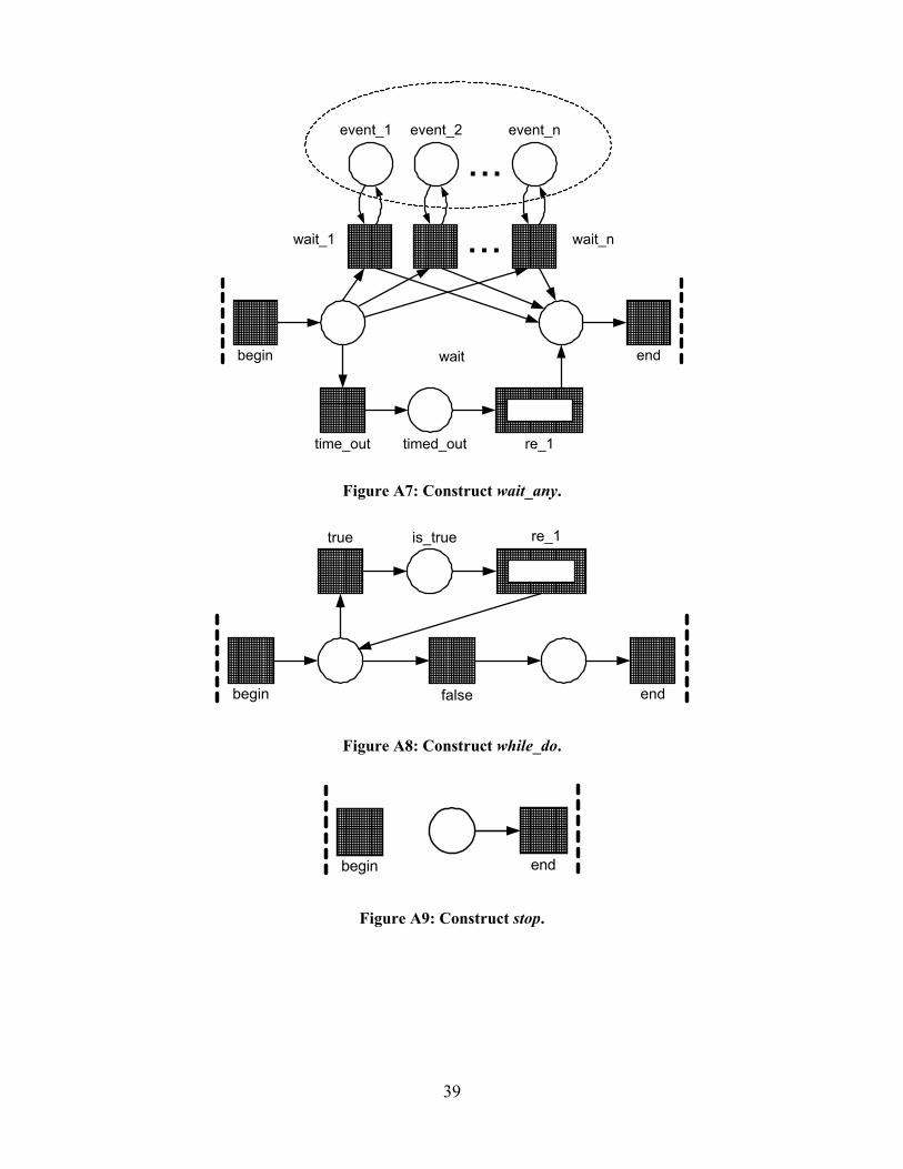
39
������������������������������������������������������������������������
��������������������������������������������������������������������
������������������������������������������������������������������������������������������������������
time_out
���������������������������������������������������
re_1
����������������������������������������������������������������������������
timed_out
begin endwait
...event_1 event_2 event_n
������������������������������������������������������������������������
��������������������������������������������������������������������
wait_1 wait_n...
Figure A7: Construct wait_any.
��������������������������������������������������������������������
����������������������������������������������������������������������������
false
��������������������������������������������������������������������������������
��������������������������������������������������������������������������������������������������������������������������������������������
����������������������������������������������������������������
re_1true is_true
begin end
Figure A8: Construct while_do.
��������������������������������������������������������������������������������
��������������������������������������������������������������������������������
begin end
Figure A9: Construct stop.