$xwrpdwhg ,pdjlqj 6shfwurphwhu l+5 l+5 2shudwlrq … · figure 2-1: options for ihr entrance and...
TRANSCRIPT

iHR Fully AutomatedImaging Spectrometer
iHR320iHR550
Operation ManualPart number J81092 rev. G


iHR Fully Automated Imaging Spectrometer rev. G (28 Feb 2013)
i
iHR Fully Automated Imaging Spectrometer
Operation Manual http://www.HORIBA.com
Rev. G

iHR Fully Automated Imaging Spectrometer rev. G (28 Feb 2013)
ii
Copyright © 2012, 2013 by HORIBA Instruments Incorporated. All rights reserved. No
part of this work may be reproduced, stored, in a retrieval system, or transmitted in any
form by any means, including electronic or mechanical, photocopying and recording,
without prior written permission from HORIBA Instruments Incorporated. Requests for
permission should be requested in writing. Portions of the software described in this
document copyright © Microsoft Corporation. LabVIEW is a trademark of National In-
struments. Globar is a registered trademark of Kanthal Globar, Inc. All rights reserved.
Information in this manual is subject to change without notice, and does not represent a
commitment on the part of the vendor.
February 2013
Part Number J81092

iHR Fully Automated Imaging Spectrometer rev. G (28 Feb 2013)
iii
Table of Contents 0: Introduction ............................................................................................. 0-1
About the iHR-series spectrometers ................................................................................................ 0-1 Chapter overview ............................................................................................................................. 0-2 Disclaimer ......................................................................................................................................... 0-3 Safety summary ............................................................................................................................... 0-5 Risks of ultraviolet exposure ............................................................................................................ 0-8 Additional risks of xenon lamps ...................................................................................................... 0-10 CE compliance statement .............................................................................................................. 0-12
1: Requirements & Installation ......................................................................... 1-1 Safety-training requirements ............................................................................................................ 1-1 Surface requirements ....................................................................................................................... 1-2 Environmental requirements ............................................................................................................ 1-3 Electrical requirements ..................................................................................................................... 1-4 Computer requirements ................................................................................................................... 1-5 Safety requirements ......................................................................................................................... 1-6 General maintenance requirements ................................................................................................. 1-7 Unpacking and installation ............................................................................................................... 1-8
2: Initial Power-up & Operation ........................................................................ 2-1 Introduction ....................................................................................................................................... 2-1 iHR operation modes ....................................................................................................................... 2-2 External interfaces and controls ....................................................................................................... 2-4 Drive operation ................................................................................................................................. 2-6 Triple-grating turret ........................................................................................................................... 2-7 Configuring hardware ....................................................................................................................... 2-8 Controlling the iHR ......................................................................................................................... 2-13 Changing gratings .......................................................................................................................... 2-18 Slit adjustments .............................................................................................................................. 2-22 Operation with dual entrance and exit ports .................................................................................. 2-23 CCD focus and rotation adjustment ............................................................................................... 2-24 Initial start-up .................................................................................................................................. 2-26
3: System Performance .................................................................................. 3-1 Diffraction-grating groove density and sys-tem performance .......................................................... 3-1 Slit settings and bandpass ............................................................................................................... 3-3 Stray-light rejection .......................................................................................................................... 3-5
4: Troubleshooting........................................................................................ 4-1 Introduction ....................................................................................................................................... 4-1 Problems .......................................................................................................................................... 4-1
5: Technical Specifications ............................................................................. 5-1 Specifications ................................................................................................................................... 5-1 Drawings .......................................................................................................................................... 5-2
6: Components & Accessories .......................................................................... 6-1 Introduction ....................................................................................................................................... 6-1 List of iHR accessories ..................................................................................................................... 6-2 Female C-mount Adapter MHR-CF ................................................................................................. 6-5 Male C-mount Adapter MAI-ICM ...................................................................................................... 6-6 LSH Series Lamp Housings ............................................................................................................. 6-7 SampleMax ...................................................................................................................................... 6-8 ACH-C Optical Chopper ................................................................................................................... 6-9 1427C Detector Housing ................................................................................................................ 6-10 220F Fiber Adapters ...................................................................................................................... 6-12 XY Fiber-Optic Mount AFO-XY ...................................................................................................... 6-15 CCD Flange to CCD ....................................................................................................................... 6-16

iHR Fully Automated Imaging Spectrometer rev. G (28 Feb 2013)
iv
Shutter ............................................................................................................................................ 6-19 Internal Filter Wheel ....................................................................................................................... 6-21 Assembling LSH + ACH-C + SampleMax + iHR320 ...................................................................... 6-24
7: Service Information ................................................................................... 7-1 Service policy ................................................................................................................................... 7-1 Return authorization ......................................................................................................................... 7-2 Warranty ........................................................................................................................................... 7-3 Notes ................................................................................................................................................ 7-4
8: CE Compliance Information .......................................................................... 8-1 Declaration of Conformity ................................................................................................................. 8-1 Supplementary Information .............................................................................................................. 8-1
9: Index ..................................................................................................... 9-1

iHR Fully Automated Imaging Spectrometer rev. G (28 Feb 2013)
v
List of figures Figure Page
Figure 0-1: iHR550 and iHR320 spectrometers 0-1
Figure 1-1: iHR spectrometer carton contents 1-9
Figure 1-2: Bottom view of iHR320 showing mounting-hole locations 1-10
Figure 1-3: Bottom view of iHR550 showing mounting-hole locations 1-11
Figure 1-4: Cover of iHR, showing turret cover screws 1-11
Figure 1-5: Inserting the grating turret 1-13
Figure 1-6: Tightening grating turret thumbscrew 1-13
Figure 1-7: Attaching the imaging flange to the iHR spectrometer 1-14
Figure 1-8: iHR electrical interface 1-15
Figure 2-1: Options for iHR entrance and exit ports 2-2
Figure 2-2: Connections to the iHR 2-4
Figure 2-3: USBSpectrometerControl window 2-9
Figure 2-4: Choosing a monochromator 2-9
Figure 2-5: Entering communications parameters 2-10
Figure 2-6: Entering the Device Display Name 2-10
Figure 2-7: Entering the Accessory information 2-11
Figure 2-8: USB Spectrometer Control program 2-13
Figure 2-9: WaveLengths window 2-17
Figure 2-10: Photograph of height-limiter 2-22
Figure 2-11: Diagram of height-limiter and actuator 2-22
Figure 2-12: Attaching imaging flange MAI to the iHR 2-24
Figure 2-13: Found New Hardware Wizard 2-26
Figure 2-14: Windows Logo Testing warning 2-26
Figure 2-15: USB Device Selection window 2-27
Figure 5-1: iHR320 dimensions, top view 5-2
Figure 5-2: iHR320 dimensions, front view 5-2
Figure 5-3: iHR320 top view, showing slits and focal plane 5-3
Figure 5-4: iHR550 dimensions, top view 5-4
Figure 5-5: iHR550 dimensions, front view 5-4
Figure 5-6: iHR550 top view, showing slits and focal plane 5-5
Figure 6-1: Dimensions of height-limiter assembly 6-1
Figure 6-2: Location of tapped holes on height-limiter assembly 6-2
Figure 6-3: Removal of height-limiter assembly 6-4
Figure 6-4: Attaching MHR-CF adapter to height-limiter assembly 6-5
Figure 6-5: Attaching MAI-ICM to iHR 6-6
Figure 6-6: Attaching LSH to height-limiter assembly 6-7
Figure 6-7: LSH-A270 adapter 6-7
Figure 6-8: LSH-series lamp housing 6-7
Figure 6-9: SampleMax attached to iHR 6-8
Figure 6-10: Schematic of 1427C with support leg 6-10
Figure 6-11: Removing front end of housing 6-10
Figure 6-12: Attaching front to height-limiter assembly 6-11
Figure 6-13: 1427C mounted on iHR side exit slit with liquid-nitrogen-cooled detector 6-11
Figure 6-14: 220F fiber-adapter mounted on iHR320 6-13
Figure 6-15: Interior of 220F with optics 6-13
Figure 6-16: Attaching AFO-XY to height-limiter assembly 6-15
Figure 6-17: Thumbscrews on AFO-XY 6-15
Figure 6-18: Schematic of MAI-IR flange 6-16

iHR Fully Automated Imaging Spectrometer rev. G (28 Feb 2013)
vi
Figure 6-19: Schematic of MAI-II flange 6-17
Figure 6-20: Schematic of MAI-I5I flange 6-18
Figure 6-21: Shutter mount for front entrance on iHR 6-19
Figure 6-22: Shutter mount for side entrance on iHR 6-20
Figure 6-23: Removing filter wheel 6-22
Figure 6-24: Schematic of filter wheel 6-22
Figure 6-25: LSH-C attached to ACH-H 6-24
Figure 6-26: SampleMax ring mounted on iHR 6-24
Figure 6-27: ACH-C connected with M28 adapters 6-25
Figure 6-28: Interior of LSH housing 6-25
Figure 6-29: Example of complete system consisting of LSH-T250 + LSH-C + ACH-C
+ SampleMax + iHR320
6-26
List of Tables Table Page
Table 1-1. Items delivered with iHR spectrometer 1-9
Table 3-1: Grating Table for the iHR320 (at 500 nm) 3-1
Table 3-2: Grating Table for the iHR550 (at 500 nm) 3-1
Table 3-3: iHR320 Slit-width vs. Bandpass with 1200 gr/mm grating at 500 nm 3-3
Table 3-4: iHR550 Slit-width vs. Bandpass with 1200 gr/mm grating at 500 nm 3-3
Table 5-1: Specifications 5-1
Table 6-1: List of iHR accessories 6-2
Table 6-2: AFW-IHR-UVVIS (nominal 3 mm filter-thickness) 6-21
Table 6-3: AFW-IHR-NIR (nominal 1 mm filter-thickness) 6-21

iHR Fully Automated Imaging Spectrometer rev. G (28 Feb 2013) Introduction
0-1
Note: Keep this and the other reference manuals near the system.
0: Introduction About the iHR-series spectrometers
Figure 0-1: iHR550 and iHR320 spectrometers
iHR-series spectrometers are automated, triple-grating spectrometers available with a
320 mm focal length (f/4.1 aperture) or a 550 nm focal length (f/6.4 aperture). Designed
for multi-channel CCD spectroscopy, these spectrometers are ideal for a variety of re-
search applications, including:
Fluorescence
Raman spectroscopy
Photoluminescence
Emission
Near-IR spectroscopy
Microscopy
iHR-series spectrometers feature a 150 nm to 15 µm wavelength-range (depending on
the grating and detector used), and excellent resolution (0.06 nm for the iHR320, and
0.025 nm for the iHR550, using a 1200 grooves/mm grating). Other features include
high-precision automated slits, a high-precision stepper drive, and a USB 2.0 computer
interface.
The drive mechanism of the iHR allows rapid and precise scanning, offering a user-
selectable step-size. The on-axis triple-grating turret, mounted on the drive, supports
three gratings which are rotated automatically via software.
The iHR may be equipped with an internal, six-position filter-wheel accessory. An in-
terface is also provided to support an external filter wheel accessory. Other available
options include an internal shutter, and dual multi-channel detector support. Tapped
holes located on the entrance and exit slits make the iHR compatible with most
HORIBA Scientific accessories. Adapters for C-mount accessories are also available.

iHR Fully Automated Imaging Spectrometer rev. G (28 Feb 2013) Introduction
0-2
Chapter overview 1: Requirements & Installation Power and environmental requirements; select the best spot
for the instrument.
2: Initial Power-up & Operation How to start and operate the iHR spectrometer.
3: System Performance How various settings affect the performance of the iHR.
4: Troubleshooting Potential sources of problems, their most probable causes,
and possible solutions.
5: Technical Specifications Instrument specifications and technical drawings.
6: Components & Accessories Accessories available for the iHR, and how to use them.
7: Service Information Service policy, warranty, and return authorizations.
8: Declaration of Conformity
9: Index

iHR Fully Automated Imaging Spectrometer rev. G (28 Feb 2013) Introduction
0-3
Disclaimer By setting up or starting to use any HORIBA Instruments Incorporated product, you are
accepting the following terms:
You are responsible for understanding the information contained in this document. You
should not rely on this information as absolute or all-encompassing; there may be local
issues (in your environment) not addressed in this document that you may need to ad-
dress, and there may be issues or procedures discussed that may not apply to your situa-
tion.
If you do not follow the instructions or procedures contained in this document, you are
responsible for yourself and your actions and all resulting consequences. If you rely on
the information contained in this document, you are responsible for:
Adhering to safety procedures
Following all precautions
Referring to additional safety documentation, such as Material Safety Data Sheets
(MSDS), when advised
As a condition of purchase, you agree to use safe operating procedures in the use of all
products supplied by HORIBA Instruments Incorporated, including those specified in
the MSDS provided with any chemicals and all warning and cautionary notices, and to
use all safety devices and guards when operating equipment. You agree to indemnify
and hold HORIBA Instruments Incorporated harmless from any liability or obligation
arising from your use or misuse of any such products, including, without limitation, to
persons injured directly or indirectly in connection with your use or operation of the
products. The foregoing indemnification shall in no event be deemed to have expanded
HORIBA Instruments Incorporated’s liability for the products.
HORIBA Instruments Incorporated products are not intended for any general cosmetic,
drug, food, or household application, but may be used for analytical measurements or
research in these fields. A condition of HORIBA Instruments Incorporated’s ac-
ceptance of a purchase order is that only qualified individuals, trained and familiar with
procedures suitable for the products ordered, will handle them. Training and mainte-
nance procedures may be purchased from HORIBA Instruments Incorporated at an ad-
ditional cost. HORIBA Instruments Incorporated cannot be held responsible for actions
your employer or contractor may take without proper training.
Due to HORIBA Instruments Incorporated’s efforts to continuously improve our prod-
ucts, all specifications, dimensions, internal workings, and operating procedures are
subject to change without notice. All specifications and measurements are approximate,
based on a standard configuration; results may vary with the application and environ-
ment. Any software manufactured by HORIBA Instruments Incorporated is also under
constant development and subject to change without notice.
Any warranties and remedies with respect to our products are limited to those provided
in writing as to a particular product. In no event shall HORIBA Instruments Incorpo-

iHR Fully Automated Imaging Spectrometer rev. G (28 Feb 2013) Introduction
0-4
rated be held liable for any special, incidental, indirect or consequential damages of any
kind, or any damages whatsoever resulting from loss of use, loss of data, or loss of
profits, arising out of or in connection with our products or the use or possession there-
of. HORIBA Instruments Incorporated is also in no event liable for damages on any
theory of liability arising out of, or in connection with, the use or performance of our
hardware or software, regardless of whether you have been advised of the possibility of
damage.

iHR Fully Automated Imaging Spectrometer rev. G (28 Feb 2013) Introduction
0-5
Safety summary The following general safety precautions must be observed during all phases of opera-
tion of this instrument. Failure to comply with these precautions or with specific warn-
ings elsewhere in this manual violates safety standards of design, manufacture and in-
tended use of instrument. HORIBA Instruments Incorporated assumes no liability for
the customer’s failure to comply with these requirements. Certain symbols are used
throughout the text for special conditions when operating the instruments:
A WARNING notice denotes a hazard. It calls at-
tention to an operating procedure, practice, or sim-
ilar that, if incorrectly performed or adhered to,
could result in personal injury or death. Do not
proceed beyond a WARNING notice until the in-
dicated conditions are fully understood and met.
HORIBA Instruments Incorporated is not respon-
sible for damage arising out of improper use of the
equipment.
A CAUTION notice denotes a hazard. It calls at-
tention to an operating procedure, practice, or sim-
ilar that, if incorrectly performed or adhered to,
could result in damage to the product. Do not pro-
ceed beyond a CAUTION notice until the indicat-
ed conditions are fully understood and met.
HORIBA Instruments Incorporated is not respon-
sible for damage arising out of improper use of the
equipment.
Ultraviolet light! Wear protective goggles, full-
face shield, skin-protection clothing, and UV-
blocking gloves. Do not stare into light.
Intense ultraviolet, visible, or infrared light! Wear
light-protective goggles, full-face shield, skin-
protection clothing, and light-blocking gloves. Do
not stare into light.
Extreme cold! Cryogenic materials must always be
handled with care. Wear protective goggles, full-
face shield, skin-protection clothing, and insulated
gloves.
Risk of electric shock! This symbol warns the user
that un-insulated voltage within the unit may have
sufficient magnitude to cause electric shock. Caution:
Caution:
Caution:
Caution:
Caution:
Warning:

iHR Fully Automated Imaging Spectrometer rev. G (28 Feb 2013) Introduction
0-6
Danger to fingers! This symbol warns the user that
the equipment is heavy, and can crush or injure the
hand if precautions are not taken.
This symbol cautions the user that excessive hu-
midity, if present, can damage certain equipment.
Hot! This symbol warns the user that hot equip-
ment may be present, and could create a risk of
fire or burns.
Read this manual before using or servicing the in-
strument.
Wear protective gloves.
Wear appropriate safety goggles to protect the
eyes.
Wear an appropriate face-shield to protect the
face.
Disconnect instrument from wall outlet (mains) before
servicing.
Caution:
Caution:
Caution:

iHR Fully Automated Imaging Spectrometer rev. G (28 Feb 2013) Introduction
0-7
Earth (ground) terminal; indicates a circuit-
common connected to grounded (earthed) chassis.
Protective earth (ground) terminal.
Alternating current.
On (electrical supply).
Off (electrical supply)
General information is given concerning operation
of the equipment.
Note:

iHR Fully Automated Imaging Spectrometer rev. G (28 Feb 2013) Introduction
0-8
Risks of ultraviolet exposure
Do not aim the UV light at anyone.
Do not look directly into the light.
Always wear protective goggles, full-face shield and skin protection clothing and
gloves when using the light source.
Light is subdivided into visible light, ranging from 400 nm (violet) to 700 nm (red);
longer infrared, “above red” or > 700nm, also called heat; and shorter ultraviolet
radiation (UVR), “below violet” or < 400nm. UVR is further subdivided into UV-A
or near-UV (320–400 nm), also called black (invisible) light; UV-B or mid-UV
(290–320 nm), which is more skin penetrating; and UV-C or far-UV (< 290 nm).
Health effects of exposure to UV light are familiar to anyone who has had sunburn.
However, the UV light level around some UV equipment greatly exceeds the level
found in nature. Acute (short-term) effects include redness or ulceration of the skin.
At high levels of exposure, these burns can be serious. For chronic exposures, there
is also a cumulative risk of harm. This risk depends upon the amount of exposure
during your lifetime. The long-term risks for large cumulative exposure include
premature aging of the skin, wrinkles and, most seriously, skin cancer and cataract.
Damage to vision is likely following exposure to high-intensity UV radiation. In
adults, more than 99% of UV radiation is absorbed by the anterior structures of the
eye. UVR can contribute to the development of age-related cataract, pterygium,
photodermatitis, and cancer of the skin around the eye. It may also contribute to
age-related macular degeneration. Like the skin, the covering of the eye or the cor-
nea, is epithelial tissue. The danger to the eye is enhanced by the fact that light can
enter from all angles around the eye and not only in the direction of vision. This is
especially true while working in a dark environment, as the pupil is wide open. The
Caution: This instrument is used in conjunction with ultraviolet light. Exposure to these radiations, even reflected or diffused, can result in serious, and some-times irreversible, eye and skin injuries.
Overexposure to ultraviolet rays threatens human health by causing:
Immediate painful sunburn
Skin cancer
Eye damage
Immune-system suppression
Premature aging

iHR Fully Automated Imaging Spectrometer rev. G (28 Feb 2013) Introduction
0-9
lens can also be damaged, but because the cornea acts as a filter, the chances are re-
duced. This should not lessen the concern over lens damage however, because cata-
racts are the direct result of lens damage.
Burns to the eyes are usually more painful and serious than a burn to the skin. Make
sure your eye protection is appropriate for this work. NORMAL EYEGLASSES OR
CONTACTS OFFER VERY LIMITED PROTECTION!
Training For the use of UV sources, new users must be trained by another member of the labora-
tory who, in the opinion of the member of staff in charge of the department, is suffi-
ciently competent to give instruction on the correct procedure. Newly trained users
should be overseen for some time by a competent person.
Caution: UV exposures are not immediately felt. The us-er may not realize the hazard until it is too late and the damage is done.

iHR Fully Automated Imaging Spectrometer rev. G (28 Feb 2013) Introduction
0-10
Warning: Xenon lamps are dangerous. Please read the fol-lowing precautions.
Additional risks of xenon lamps
Among the dangers associated with xenon lamps
are:
Burns caused by contact with a hot xenon lamp.
Fire ignited by hot xenon lamp.
Interaction of other nearby chemicals with intense ultraviolet, visible, or infrared
radiation.
Damage caused to apparatus placed close to the xenon lamp.
Explosion or mechanical failure of the xenon lamp.
Visible radiation Any very bright visible light source will cause a human aversion response: we either
blink or turn our head away. Although we may see a retinal afterimage (which can last
for several minutes), the aversion response time (about 0.25 seconds) normally protects
our vision. This aversion response should be trusted and obeyed. NEVER STARE AT
ANY BRIGHT LIGHT-SOURCE FOR AN EXTENDED PERIOD. Overriding the
aversion response by forcing yourself to look at a bright light-source may result in per-
manent injury to the retina. This type of injury can occur during a single prolonged ex-
posure. Excessive exposure to visible light can result in skin and eye damage.
Visible light sources that are not bright enough to cause retinal burns are not necessari-
ly safe to view for an extended period. In fact, any sufficiently bright visible light
source viewed for an extended period will eventually cause degradation of both night
and color vision. Appropriate protective filters are needed for any light source that
causes viewing discomfort when viewed for an extended period of time. For these rea-
sons, prolonged viewing of bright light sources should be limited by the use of appro-
priate filters.
The blue-light wavelengths (400–500 nm) present a unique hazard to the retina by
causing photochemical effects similar to those found in UV-radiation exposure.
Infrared radiation Infrared (or heat) radiation is defined as having a wavelength between 780 nm and 1
mm. Specific biological effectiveness “bands” have been defined by the CIE (Commis-
sion Internationale de l’Eclairage or International Commission on Illumination) as fol-
lows:
• IR-A (near IR) (780–1400 nm)
• IR-B (mid IR) (1400–3000 nm)
• IR-C (far IR) (3000 nm–1 mm)

iHR Fully Automated Imaging Spectrometer rev. G (28 Feb 2013) Introduction
0-11
The skin and eyes absorb infrared radiation (IR) as heat. Workers normally notice ex-
cessive exposure through heat sensation and pain. Infrared radiation in the IR-A that
enters the human eye will reach (and can be focused upon) the sensitive cells of the ret-
ina. For high irradiance sources in the IR-A, the retina is the part of the eye that is at
risk. For sources in the IR-B and IR-C, both the skin and the cornea may be at risk from
“flash burns.” In addition, the heat deposited in the cornea may be conducted to the lens
of the eye. This heating of the lens is believed to be the cause of so called “glassblow-
ers’ ” cataracts because the heat transfer may cause clouding of the lens.
Retinal IR Hazards (780 to 1400 nm): possible retinal lesions from acute high irra-
diance exposures to small dimension sources.
Lens IR Hazards (1400 to 1900 nm): possible cataract induction from chronic lower
irradiance exposures.
Corneal IR Hazards (1900 nm to 1 mm): possible flashburns from acute high irradi-
ance exposures.
Who is likely to be injured? The user and anyone exposed to the radiation or xenon
lamp shards as a result of faulty procedures. Injuries may be slight to severe.

iHR Fully Automated Imaging Spectrometer rev. G (28 Feb 2013) Introduction
0-12
CE compliance statement The iHR-series spectrometers are tested for compliance with both the EMC Directive
89/336/EEC and the Low Voltage Directive for Safety 73/23/EEC, and bear the inter-
national CE mark as indication of this compliance. HORIBA Instruments Incorporated
guarantees the product line’s CE compliance only when original HORIBA Instruments
Incorporated supplied parts are used. Chapter 8 herein provides a table of all CE Com-
pliance tests and standards used to qualify this product.

iHR Fully Automated Imaging Spectrometer rev. G (28 Feb 2013) Requirements & Installation
1-1
1: Requirements & Installation Safety-training requirements
Every user of the iHR-series spectrometers must know general and specific safety pro-
cedures before operating the instrument. For example, proper training includes (but is
not limited to):
Understanding the risks of exposure to ultraviolet, visible, and infrared light, and
how to avoid unsafe exposures to these types of radiation
Safe handling for all chemicals and other samples used in the instrument
Safety-training may be purchased from HORIBA Scientific. Contact your Sales Repre-
sentative or the Service Department for details.

iHR Fully Automated Imaging Spectrometer rev. G (28 Feb 2013) Requirements & Installation
1-2
Surface requirements A sturdy table- or bench-top
Surface must hold 90 kg (200 lbs.).
Surface should be about 27″ × 72″ (69 cm × 183 cm) to hold spectrometer, computer,
and accessories comfortably.
Overhead clearance should be at least 36" (91 cm).

iHR Fully Automated Imaging Spectrometer rev. G (28 Feb 2013) Requirements & Installation
1-3
Environmental requirements Recommended operating temperature range 20–30°C (68–86°F)
Maximum temperature fluctuation ± 2°C around average ambient temperature
Ambient relative humidity < 75%
Low levels of dust, smoke, and corrosive chemicals
No special ventilation
Caution: Excessive humidity can damage the optics.
Note: For optimum performance, keep the ambient temperature be-tween 20 and 30°C.

iHR Fully Automated Imaging Spectrometer rev. G (28 Feb 2013) Requirements & Installation
1-4
Caution: HORIBA Scientific is not liable for damage from line surges and voltage fluctuations. A surge pro-tector is strongly recommended for minor power fluc-tuations. For more severe voltage variations, use a generator or uninterruptible power supply. Improper
line voltages can damage the equipment severely.
Warning: The iHR spectrometer is equipped with a three-conductor power cord that is connected to the system frame (earth) ground. This ground provides a return path for fault current from equipment malfunc-tion or external faults. For all instruments, ground con-tinuity is required for safe operation. Any discontinuity in the ground line can make the instrument unsafe for use. Do not operate this system from an un-grounded source.
Electrical requirements The iHR operates from a 24 V DC input. This is provided by the universal input (100
V–240 V, 1.6 A), 24 V DC @ 2.1 A output external brick power supply (J964007) sup-
plied with the instrument. The power supply is plugged into a standard wall outlet
(mains) using a standard three-conductor power cord (J98015 for 110 V or J98020 for
220 V).

iHR Fully Automated Imaging Spectrometer rev. G (28 Feb 2013) Requirements & Installation
1-5
Computer requirements The iHR provides a USB interface with a built in USB 2.0 hub for communications
with a host computer. It also provides an additional USB port for connecting to a down-
stream USB device.
The iHR is controlled by HORIBA Scientific’s Spectrometer Utilities program,
SynerJY® data acquisition software, or with LabVIEW™ VIs. Computer requirements
for the iHR are:
One free USB port for USB communications
DVD drive
Meets the requirements specified by the user’s operating system
See the User’s Guide for SynerJY®
Software Version 3.5 for computer software
and hardware requirements, such as Windows® 2000, Vista, XP or 7 (32-bit
compatibility mode); PC is typically configured with 3 or more USB ports; 1
GB RAM, minimum; 1GB available hard-disk space

iHR Fully Automated Imaging Spectrometer rev. G (28 Feb 2013) Requirements & Installation
1-6
Caution: Never touch the grating surface—not even with lens tissue. Damage can easily occur and de-grade performance. Such damage is not covered by warranty. Fingerprints on a grating surface cause per-manent damage. If fingerprints get on the grating sur-face, do not attempt to clean them.
Safety requirements Observe the following precautions to prevent possible damage to the iHR:
Do not connect or disconnect any cables to or from the iHR when the instru-
ment is powered on.
Keep the grating in a closed instrument or storage container at all times.
Do not touch the grating surface.

iHR Fully Automated Imaging Spectrometer rev. G (28 Feb 2013) Requirements & Installation
1-7
General maintenance requirements We recommend periodically cleaning the external surfaces of the iHR by wiping them
down with a clean, damp cloth. Only perform this procedure on external surfaces. Do
not use any other solvents, soaps, or abrasives when cleaning, for these products can
damage surface finishes.
While the mirrors and gratings of the iHR require no routine maintenance, exercise care
to prevent damage to their surfaces. Should dust particles accumulate on the grating
surface, it is better to leave them rather than risk possible surface damage caused by
cleaning.
iHR Fully Automated Imaging Spectrometer rev. G (28 Feb 2013) Requirements & Installation
1-8
Unpacking and installation Introduction
Before use, set up your iHR spectrometer and all accompanying components. The in-
stallation of your HORIBA Scientific spectrometer and application software has several
separate stages that must be completed in the order below for the system to operate
properly.
Unpacking and equipment inspection
Installing the tilt feet
Installing the grating
Installing a CCD detector (optional)
Installing USB Spectrometer Utilities software
Connecting electrical interface cables
Additional procedures for mounting accessories to the iHR are found in Appendix D.
Caution: The spectrometer and accessories are delicate. Mishandling may seriously damage their components. The HORIBA Instruments Incorporated warranty on the iHR does not cover damage to the system’s optical components that arises as a result of improper han-dling.
Note: Many public carriers will not recognize a claim for concealed damage if it is reported later than 15 days after delivery. In case of a claim, inspection by an agent of the carrier is required. For this rea-son, the original packing material should be retained as evidence of alleged mishandling or abuse. While HORIBA Instruments Incorpo-rated assumes no responsibility for damage occurring during transit,
the company will make every effort to aid and advise.

iHR Fully Automated Imaging Spectrometer rev. G (28 Feb 2013) Requirements & Installation
1-9
iHR spectrometer carton contents
Figure 1-1: iHR spectrometer carton contents
Table 1-1. Items delivered with iHR spectrometer
Quantity Item Part number
1 iHR spectrometer iHR 320 or iHR
550
4 Tilt feet J992024
1 Shielded USB cable, A to B J980087
1 24 V AC to DC power supply J964007
1 Single-cell sample-holder J351697
1 iHR spectrometer operation manual J81092
1 HORIBA Scientific USB Spectrometer Utilities CD CSW-USB-
MONOS
1 Power cord (110 V)
(220 V)
J98015
J98020
1 CCD Resolution Flange (only with units configured for
spectrograph operation)
MAI-IR
1 Metric accessories kit (including Allen keys and screws) J992029
Directions
1 Unpack the iHR spectrometer.
a Carefully open the iHR spectrometer shipping carton.

iHR Fully Automated Imaging Spectrometer rev. G (28 Feb 2013) Requirements & Installation
1-10
Caution: Watch your fingers!
b Remove the foam-injected top piece and any other shipping restraints in
the carton.
c With assistance, carefully lift the instrument from the carton, and rest it
on the side of the laboratory bench where the system will stay.
d Place the instrument in its permanent location.
e Inspect for previously hidden damage.
Notify the carrier and HORIBA Scientific if any is found.
f Check the packing list to verify that all components and accessories are
present.
2 Install tilt feet.
a Find the four tilt feet (J992024) shipped with the iHR.
b Screw the tilt feet into the four M8 tapped holes found at the base of the
instrument (see figures below for iHR320 and iHR550).
Set the height and tilt of the unit by adjusting the feet.
Figure 1-2: Bottom view of iHR320 showing mounting-hole locations

iHR Fully Automated Imaging Spectrometer rev. G (28 Feb 2013) Requirements & Installation
1-11
Figure 1-3: Bottom view of iHR550 showing mounting-hole locations
c When the height and tilt of the instrument are satisfactory, lock the feet
into place by tightening the nuts of the feet against the body of the unit.
3 Install the grating.
a If you have the optional circular turret cover, using a PH1 (Phillips
head) screwdriver, loosen the three screws of the iHR turret cover and
remove the turret cover.
Figure 1-4: Cover of iHR, showing turret cover screws
iHR Fully Automated Imaging Spectrometer rev. G (28 Feb 2013) Requirements & Installation
1-12
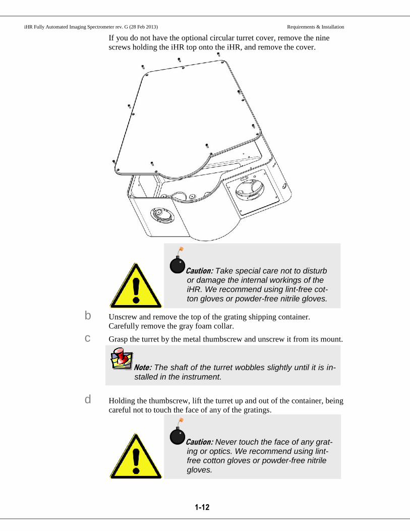
Note: The shaft of the turret wobbles slightly until it is in-stalled in the instrument.
If you do not have the optional circular turret cover, remove the nine
screws holding the iHR top onto the iHR, and remove the cover.
b Unscrew and remove the top of the grating shipping container.
Carefully remove the gray foam collar.
c Grasp the turret by the metal thumbscrew and unscrew it from its mount.
d Holding the thumbscrew, lift the turret up and out of the container, being
careful not to touch the face of any of the gratings.
Caution: Take special care not to disturb or damage the internal workings of the iHR. We recommend using lint-free cot-ton gloves or powder-free nitrile gloves.
Caution: Never touch the face of any grat-ing or optics. We recommend using lint-free cotton gloves or powder-free nitrile gloves.
iHR Fully Automated Imaging Spectrometer rev. G (28 Feb 2013) Requirements & Installation
1-13
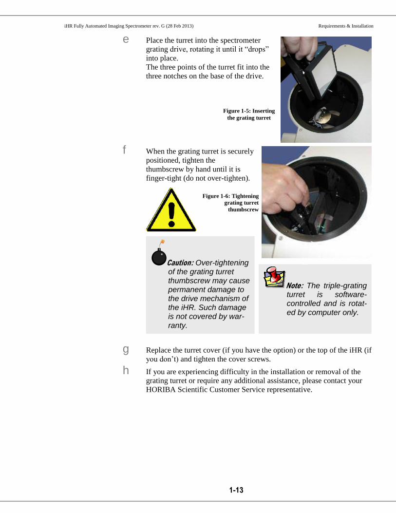
Caution: Over-tightening of the grating turret thumbscrew may cause permanent damage to the drive mechanism of the iHR. Such damage is not covered by war-ranty.
Note: The triple-grating turret is software-controlled and is rotat-ed by computer only.
e Place the turret into the spectrometer
grating drive, rotating it until it “drops”
into place.
The three points of the turret fit into the
three notches on the base of the drive.
f When the grating turret is securely
positioned, tighten the
thumbscrew by hand until it is
finger-tight (do not over-tighten).
g Replace the turret cover (if you have the option) or the top of the iHR (if
you don’t) and tighten the cover screws.
h If you are experiencing difficulty in the installation or removal of the
grating turret or require any additional assistance, please contact your
HORIBA Scientific Customer Service representative.
Figure 1-5: Inserting
the grating turret
Figure 1-6: Tightening
grating turret
thumbscrew

iHR Fully Automated Imaging Spectrometer rev. G (28 Feb 2013) Requirements & Installation
1-14
4 Install an optional CCD camera iHR spectrograph models purchased with HORIBA Scientific CCD cameras are
shipped with the CCD flange already attached to the camera. HORIBA
Scientific CCDs are focused and aligned at the factory. When the CCD cameras
are installed in the iHR, using the procedure and diagram below, they should be
properly aligned and require no further adjustments.
If you are using a CCD not manufactured by HORIBA Scientific, the flange
requires mounting to the CCD (see the CCD Flange Mounting Procedure in
Chapter 6).
a Insert the tube of the CCD flange into the CCD port of the iHR.
b Make sure that the flange pin is aligned with the corresponding slot.
c Push the flange into the iHR until it stops.
The flange will touch the focus wheel.
d Rotate the CCD clockwise until it stops.
e Tighten the flange clamp using a 2.5 mm Allen key.
See “Chapter 4: CCD Focus and Rotation Adjustment Mechanisms” for
more details on positioning the CCD camera.
Figure 1-7: Attaching the imaging flange to the iHR spectrometer
Imaging flange (MA-II for iHR320, or MAI-I5I for iHR550).
a
b
c
d

iHR Fully Automated Imaging Spectrometer rev. G (28 Feb 2013) Requirements & Installation
1-15
5 Install the USB Spectrometer Utilities software.
a Start Windows® if you have not already done so.
b Make sure all programs are closed.
c Insert the CD labeled USB Spectrometer Utilities (CSW-USB-
SUPPORT-MONO) into your DVD drive.
d If Autorun is enabled installation will begin automatically. If Autorun is
not enabled, execute the Setup.exe file by selecting My
Computer>USB Utility>Setup.exe.
The InstallShield Wizard dialog box appears.
e Click the Next button.
f Click the Next button to accept the default destination location
(C:\Program Files\Jobin Yvon), or click the Browse button to select a
different location.
g Review the current settings, then click the Next button to continue the
installation.
h When the installation is complete, click the Finish button.
i Remove the CD from the DVD drive.
6 Connect the electrical interface cables.
a Connect the 5-pin DIN connector of the 24 V AC to DC power supply
(J964007) to the power-connector interface on the back panel of the
iHR.
Figure 1-8: iHR electrical interface
b Connect the female end of the power cord (J98015 for 110 V or J98020
for 220 V) to the power supply.
c Plug the wall-outlet (mains) end of the power cord into a properly
grounded outlet to provide a chassis-to-earth ground.
d Find a USB port on your computer, and connect the USB
Note: LabSpec Users: Do NOT install USB Spectrometer Utili-ties. Instead follow instructions for installing LabSpec, or con-tact HORIBA Scientific for assistance. If you are using applica-tion software other than USB Spectrometer Utilities, follow the installation procedure provided with that software.

iHR Fully Automated Imaging Spectrometer rev. G (28 Feb 2013) Requirements & Installation
1-16
Note: Use the USB hub ONLY for low-current devices. This jack is not rec-ommended to con-nect to Synapse®, Symphony® II, or another iHR.
Note: The first time that the unit is connected to the computer, Windows® detects a new USB de-vice and automatically installs the appropriate driver (see Chapter 4: Operation).
communications cable (J980076) (A end) to the computer.
e Connect the other end of the USB cable (B end) to the USB interface on
the back panel of the iHR.
f Connect another optional USB device to the USB hub.
g Connect the optional CCD shutter to the SHUTTER jack.

iHR Fully Automated Imaging Spectrometer rev. G (28 Feb 2013) Initial Power-up & Operation
2-1
2 : Initial Power-up & Operation Introduction
This chapter covers the steps necessary to initially power-up and operate the iHR. In
addition, detector-head issues related to proper CCD focus and alignment to a spectro-
graph are discussed in detail.
The topics listed below provide information about the abilities and functions of your
iHR.
Operation modes
External interfaces
Drive operation
Triple-grating turret
Slit adjustments
Operation with dual exit and entrance ports
CCD rotation and adjustment mechanisms
Internal filter-wheel operation
To turn on and operate your spectrometer, follow the steps in the order listed below.
The included USB Spectrometer Utilities programs only allow you to control your
spectrometer, and are not equipped to control detectors or accessories. SynerJY® spec-
troscopic applications software is recommended for the control and integration of addi-
tional system components.
Initial power-up
Configuring hardware
Controlling the iHR
iHR Fully Automated Imaging Spectrometer rev. G (28 Feb 2013) Initial Power-up & Operation
2-2
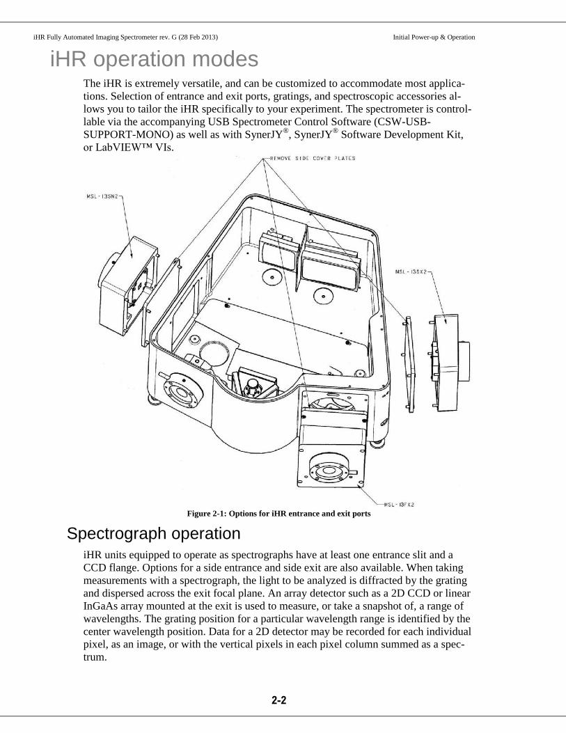
iHR operation modes The iHR is extremely versatile, and can be customized to accommodate most applica-
tions. Selection of entrance and exit ports, gratings, and spectroscopic accessories al-
lows you to tailor the iHR specifically to your experiment. The spectrometer is control-
lable via the accompanying USB Spectrometer Control Software (CSW-USB-
SUPPORT-MONO) as well as with SynerJY®, SynerJY
® Software Development Kit,
or LabVIEW™ VIs.
Figure 2-1: Options for iHR entrance and exit ports
Spectrograph operation iHR units equipped to operate as spectrographs have at least one entrance slit and a
CCD flange. Options for a side entrance and side exit are also available. When taking
measurements with a spectrograph, the light to be analyzed is diffracted by the grating
and dispersed across the exit focal plane. An array detector such as a 2D CCD or linear
InGaAs array mounted at the exit is used to measure, or take a snapshot of, a range of
wavelengths. The grating position for a particular wavelength range is identified by the
center wavelength position. Data for a 2D detector may be recorded for each individual
pixel, as an image, or with the vertical pixels in each pixel column summed as a spec-
trum.

iHR Fully Automated Imaging Spectrometer rev. G (28 Feb 2013) Initial Power-up & Operation
2-3
Monochromator operation iHR units equipped to operate as monochromators are configured with an entrance and
an exit slit. Options are available for a side exit slit and a side entrance slit. As the name
suggests, a monochromator is used to select a single wavelength of light. Here are four
typical applications for the iHR when configured as a monochromator:
Scanning
monochromator
The instrument can be used to measure the spectral output of
emitted light. The light can come from the sun, a laser diode, a
glow discharge, etc.
Tunable light
source
With a broadband light-source directly coupled to the entrance
slit, the iHR can provide a specific bandpass (range of wave-
lengths) at the exit. Changing the slit-width varies the spectral
bandpass.
Spectral filter The iHR can be used to select a particular bandpass of light, at
different user-selected wavelengths.
Fixed wavelength
measurement
The iHR, when set to a fixed wavelength and bandpass with a
single-channel detector coupled to the exit slit, can monitor var-
iations in an incoming light-signal, such as laser power.

iHR Fully Automated Imaging Spectrometer rev. G (28 Feb 2013) Initial Power-up & Operation
2-4
External interfaces and controls Power switch
Turns on and off the power.
Power status LED
Illuminates green to indicate that the unit is powered on.
Power connector
Receptacle that connects the 24 V AC to DC power supply to the iHR via
a 5-pin DIN connector, supplying power to the unit.
External I2C
Not used; for future development.
USB Sta-tus LED
Illuminates green to indicate that USB communications exist between the
iHR and the operating computer.
USB In-terface
Accepts the standard USB-B end of a USB communications cable, allow-
ing USB 2.0 communications between the iHR and the operating com-
puter.
USB Hub Built-in USB 2.0 hub for easy expansion of HORIBA Scientific systems
(using a standard USB-A connector) without the need for an external
USB expansion hub.
Figure 2-2: Connections to the iHR
USB Hub Status LED
Illuminates green to indicate that USB communications exist between the
iHR and some external device interfaced to the iHR via the USB hub.
Note: Use the USB hub ONLY for low-current devices. This jack is not recommended to connect to Synapse®, Symphony® II, or another iHR.
Power connector
USB interface
USB Hub
Purge port

iHR Fully Automated Imaging Spectrometer rev. G (28 Feb 2013) Initial Power-up & Operation
2-5
External Filter Wheel
Establishes communications between a HORIBA Scientific external filter
wheel and the iHR. The External Filter Wheel requires cable J400743.
Shutter Connector
Provides the user the option of connecting a shutter cable to the iHR via a
BNC connection.

iHR Fully Automated Imaging Spectrometer rev. G (28 Feb 2013) Initial Power-up & Operation
2-6
Drive operation The iHR uses a precision worm-wheel gear drive mechanism under stepper-motor con-
trol which enables a user to drive precisely to a given wavelength or scan over a wave-
length range. The drive has a scan range of 0 nm to 1500 nm (for a 1200 gr/mm grat-
ing). The wavelength resolution of the drive is user selectable with a minimum step size
of 0.002 nm (with a 1200 gr/mm grating). The drive must be initialized upon powering
up. The initialization process precisely homes the drive mechanism, allowing for very
accurate and repeatable wavelength settings. The drive will hold position indefinitely as
long as the unit is powered up. If the system is powered down, there can be a small shift
in drive position.
The drive requires no backlash correction when moving in the direction of increasing
wavelength. We therefore recommend that users scan from lower to higher wave-
lengths. When the system is directed to move from a higher wavelength to a lower
wavelength, an automatic backlash correction is performed. Although the wavelength
accuracy and precision of the drive is unaffected, the backlash operation adds addition-
al time to the scan.
When moving from lower to higher wavelength, the drive scan speed is approximately
160 nm/s.
iHR Fully Automated Imaging Spectrometer rev. G (28 Feb 2013) Initial Power-up & Operation
2-7
Triple-grating turret The iHR’s unique turret design allows it to maintain on-axis grating rotation during
scanning, delivering superior optical performance. The triple grating turret supports
three gratings; rotation is controlled by a single stepper-motor. Grating selection is
software-controlled. The operation for changing the grating is automated and takes ap-
proximately 30 seconds per grating.
Additional turrets may be purchased for the iHR320 and iHR550. The grating turret is
kinematically mounted, allowing the user to interchange turrets without the need for re-
alignment.
iHR Fully Automated Imaging Spectrometer rev. G (28 Feb 2013) Initial Power-up & Operation
2-8
Configuring hardware If you received your copy of USB Spectrometer Utilities with your iHR, the software
has already been preconfigured to find and control your spectrometer. Once the spec-
trometer is identified, you must create a hardware configuration.
1 The USB Device Selection dialog box appears the first time the spectrometer is used, indicating that an exact hardware match has not been found. The window lists all of the compatible hardware, i.e., spectrometers, attached to
your computer. Highlight the hardware description that matches your iHR and
click the OK button. If more than one iHR is listed, chose the correct one based
on serial number.
2 To configure using USB Spectrometer Utilities software, select Start>Programs>Jobin Yvon>USBSpectrometerControl. The USB Spectrometer Control program allows you to initialize the instrument
as well as enter or change the wavelength position, mirror position, and slit-
widths. It also allows you to configure and change the filter-wheel position if
your iHR is equipped with an internal filter wheel. If using SynerJY® software,
see the Hardware Configuration topics located in the SynerJY Installation Guide
and Help file.
3 If adding a new spectrometer, select the appro-priate model from the Choose Spectrometer drop-down list and click the Initialize button; proceed to Step 10.
Note: The USB Spectrometer Control program only allows you to configure your spectrometer (and optional internal filter wheel), and is not equipped to create hardware configurations for detectors and accessories. You must use SynerJY® or the software provided with your detector to create a system con-figuration.

iHR Fully Automated Imaging Spectrometer rev. G (28 Feb 2013) Initial Power-up & Operation
2-9
If you are installing a new ver-
sion of USB Spectrometer Util-
ities, your spectrometer will not
be available in the Choose Spectrometer drop-down list;
click the Add button.
4 Select iHR320 or iHR550 from the Device Name list, and click the Next > button.
Figure 2-3:
USBSpectrometerControl window
Figure 2-4: Choosing a monochromator

iHR Fully Automated Imaging Spectrometer rev. G (28 Feb 2013) Initial Power-up & Operation
2-10
5 Enter the Communi-cations Parame-ters for the device. Select HJY USB
as the Controller drop-down menu,
USB from the
Communications Type drop-down
menu and select
iHR320 or iHR550 from the drop-down menu. Click the Next > button.
6 Enter the Device Display Name (the model name ap-pears as the default) and click the Next > button.
Figure 2-5: Entering communications parameters
Figure 2-6: Entering the Device Display Name
iHR Fully Automated Imaging Spectrometer rev. G (28 Feb 2013) Initial Power-up & Operation
2-11
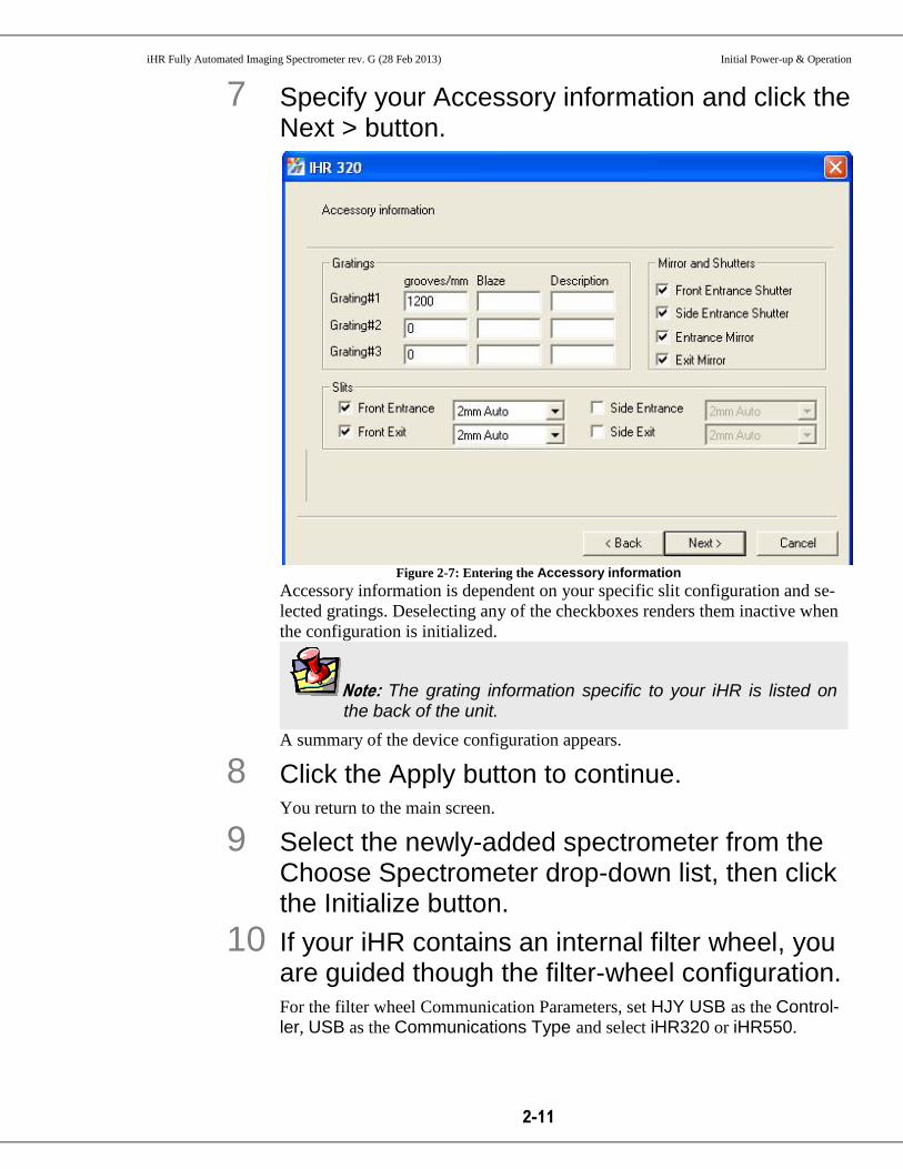
7 Specify your Accessory information and click the Next > button.
Figure 2-7: Entering the Accessory information
Accessory information is dependent on your specific slit configuration and se-
lected gratings. Deselecting any of the checkboxes renders them inactive when
the configuration is initialized.
A summary of the device configuration appears.
8 Click the Apply button to continue. You return to the main screen.
9 Select the newly-added spectrometer from the Choose Spectrometer drop-down list, then click the Initialize button.
10 If your iHR contains an internal filter wheel, you are guided though the filter-wheel configuration. For the filter wheel Communication Parameters, set HJY USB as the Control-ler, USB as the Communications Type and select iHR320 or iHR550.
Note: The grating information specific to your iHR is listed on the back of the unit.
iHR Fully Automated Imaging Spectrometer rev. G (28 Feb 2013) Initial Power-up & Operation
2-12
11 Enter the appropriate Wavelength Control, Slits, and Mirrors information. These fields are only accessible after spectrometer initialization.

iHR Fully Automated Imaging Spectrometer rev. G (28 Feb 2013) Initial Power-up & Operation
2-13
Controlling the iHR The USB Spectrometer Utilities CD supplied with the iHR contains two programs that
can be used together to control the spectrometer:
The USB Spectrometer Control program allows you to enter or change the wave-
length position, mirror position, control slits, and filter-wheel position (if your iHR
is equipped with an internal filter wheel).
The USB Mono Config program allows you to select the appropriate grating as well
as change the offset.
USB Spectrometer Control
1 Make sure your hardware is configured. Select Start>Programs>Jobin Yvon>USBSpectrometerControl.
2 Set the fields to the desired settings. The Wavelength Control area moves
the spectrometer to
the specified wave-
length (in nm), as an
incremental increase
or decrease.
The Slits area ad-
justs the slit-width
(in mm). Slits op-
tions are: Front En-trance, Front Exit, Side Entrance, and
Side Exit. Click on
fields, and enter the
appropriate values.
Note: USB Spectrometer Utilities programs only allow you to control your spectrometer (and optional internal filter wheel) and are not equipped to control detectors and accessories. You must use SynerJY® or the software provided with your detector to control addi-tional system components.
Figure 2-8: USB Spectrometer Control program

iHR Fully Automated Imaging Spectrometer rev. G (28 Feb 2013) Initial Power-up & Operation
2-14
Grating shows the
grating that has been
specified in the
hardware configura-
tion. Clicking the
Grating drop-down
menu displays other
grating types that are
available with the
active
monochromator.
The Mirrors area ad-
justs the mirrors at
the entrance and exit
slits in accordance
with the hardware
configuration. Click
Side or Front to ad-
just the mirrors for
the entrance slit and
exit slit. The selected
position appears in
bold, and the graph-
ical switch moves to reflect the selection.
USB Mono Configuration
1 Make sure your hardware is configured.
2 Select Start>Programs>Jobin Yvon>USBMonoConfig.
3 Select the tab for the parameter that you want to adjust, and enter the ap-propriate infor-mation. Tabs are available for:

iHR Fully Automated Imaging Spectrometer rev. G (28 Feb 2013) Initial Power-up & Operation
2-15
Mono – Select the active spectrometer.
Grating – Select the grating from the gratings available for the active spectrom-
eter; perform grating calibration procedure.
Drive Correction Table – Perform drive correction and offset.
Filter Wheel – Select and
enable internal filter
wheel.
Slits – Specify frequency, maximum step-size, and backlash.
Mirrors – Enable mirrors.
Other – Enter shutter information.
4 After all parameters are specified, click the Write button to store the entered values.
5 Click the OK button to exit USB Mono Config.
Calibrating the grating using USB Spectrometer Utili-ties
The grating calibration procedure serves as an initial check, before running an experi-
ment, that your system’s monochromator is properly calibrated and aligned.
1 Set up a calibration source, such as a mercury lamp, on the front entrance slit of the iHR.
2 Make sure your detector is mounted onto the exit port.
3 Select Start>Programs>Jobin Yvon>USBSpectrometerControl.
4 Set the slit-width to a minimum (~0.01 mm) and manually adjust the height limiter to 1 mm.
5 Set the Position to a reference wavelength value (such as a mercury line at 546.07 nm).
Note: You must use the software provided with your detector (in con-junction with USB Spectrometer Utilities) to collect a spectrum and de-termine the peak-pixel position corresponding to the reference peak. If using SynerJY®, see the Monochromator Calibration procedure of the Help file.
Figure 2-3: USB Mono Configuration program

iHR Fully Automated Imaging Spectrometer rev. G (28 Feb 2013) Initial Power-up & Operation
2-16
6 Start the detector software, and follow the ap-propriate procedure for using a CCD or other ar-ray detector, or single-channel detector (PMT, DSS, or lock-in).
For multi-channel detectors (CCD, array)
a Set the x-axis to display in Pixels.
b Collect a spectrum and note the peak-pixel position corresponding to the
reference peak.
If the iHR is calibrated correctly, the peak-pixel position should be at the
center pixel of the CCD chip (for example, for a 1024-pixel-wide CCD
chip, the peak should appear at pixel 512).
c If the peak does not appear at the central pixel, change the center
wavelength position until the peak appears in the center of the chip.
d Record the observed position of the reference peak.
For single-channel detectors (PMT, DSS)
a Scan the grating in the region of the reference peak until the detector
reads the maximum signal.
b Record the observed position of the reference peak.
7 Select the Gratings tab, then select the Grating # you are calibrating from the drop-down list.
8 Click the Cali-brate Grat-ing… button. The WaveLengths window opens:

iHR Fully Automated Imaging Spectrometer rev. G (28 Feb 2013) Initial Power-up & Operation
2-17
9 Enter the The-oretical peak value, then click the Set button.
10 Click the Ob-served radio button, and en-ter the ob-served refer-ence peak val-ue, then click the Set button.
11 Click the Next > button.
12 Click the Done button to accept the calibration offset, or click the Cancel button to discard the change. The grating calibration is saved to memory.
Figure 2-9: WaveLengths window

iHR Fully Automated Imaging Spectrometer rev. G (28 Feb 2013) Initial Power-up & Operation
2-18
Changing gratings Introduction
Although a single-grating turret is included in the basic configuration for an iHR320 or
iHR550 spectrometer, you can order an additional grating turret (or turrets) at the time
of your initial spectrometer purchase. In order for the instrument to work properly and
correctly identify which turret is used, a separate firmware configuration and a separate
software configuration are both required for each grating turret. When changing from
one grating turret to another, you must load the appropriate firmware using the USB
Spectrometer Utilities software according to the procedure described below.
If you ordered a new iHR spectrometer with two grating turrets, the firmware for turret
1 is preloaded. If you purchased SynerJY® software, the firmware files for Turret 1 and
Turret 2 are burned onto the SynerJY® installation disk, in addition to the SynerJY
®
software configurations for Turret 1 and Turret 2.
There are two options for the iHR chassis:
With a circular port on top for changing gratings
Without a circular port for changing gratings.
If you have the option with no port, you will have to remove the top of the iHR case,
and take extra care not to touch or damage the internal optics.
Procedure
1 Insert the SynerJY disk into the DVD drive of your host computer.
2 Navigate to the Configurations folder on the
SynerJY® CD, and copy this folder to your host
computer’s desktop.
3 Install USB Spectrometer Utilities software ac-cording to the procedure on page 1-14 of this manual.
Caution: Never touch the face of any grating or optics. We recommend using lint-free cotton gloves or pow-der-free nitrile gloves.

iHR Fully Automated Imaging Spectrometer rev. G (28 Feb 2013) Initial Power-up & Operation
2-19
4 Remove Turret 1, put it in the appropriate stor-age container, and replace it with Turret 2 as shown on pages 1-11 and 1-12 of this manual.
5 Open the USB SpectrometerConfig utility pro-gram. This program allows you to configure the spectrometer firmware to accept the
new gratings on Turret 2.
The JYUSBMonoConfig window appears:
6 Click the Load From… button.
The Open window appears:

iHR Fully Automated Imaging Spectrometer rev. G (28 Feb 2013) Initial Power-up & Operation
2-20
7 Navigate to the Configurations folder on
your host computer’s desktop, where you see two files named Turret 1 FirmWare Turret 2 FirmWare
8 Choose the appropriate firmware file (in this
case Turret 2 FirmWare) and click the
Open button.
The Open window closes when the file loads.
9 Click the Write button, wait until the process is finished, then exit the program by clicking the red X in the upper right-hand corner.

iHR Fully Automated Imaging Spectrometer rev. G (28 Feb 2013) Initial Power-up & Operation
2-21
10 Cycle the power on the iHR spectrometer.
11 Open SynerJY® software, and select the config-
uration for Turret 2. To load the configurations for Turret 1 and Turret 2, follow the instructions in
the SynerJY User’s Guide on page 17, but select Load Factory Configuration
in Step 4. Follow the prompts from the wizard, and select the correct SynerJY
configuration from the Configurations folder now on the host computer’s
desktop. A typical file name is ConfigTurret2.jyc.
12 To revert back to Turret 1, follow the same pro-cedure, but this time load the firmware for Turret 1, and select the SynerJY configuration for Tur-ret 1.

iHR Fully Automated Imaging Spectrometer rev. G (28 Feb 2013) Initial Power-up & Operation
2-22
Slit adjustments Introduction
The slits of the iHR are fully automated. The width of the slit opening is controlled via
software. Having the proper slit-width is critical, for it directly affects the throughput
and wavelength resolution of the system. The slit-height also has an effect on resolution
and throughput, although to a lesser extent. Slit-height is manually adjusted by a height
limiter. See Chapter 5: System Performance for a more complete discussion of this top-
ic.
Automated slits The motorized, adjustable slits of the iHR are controlled remotely by computer. Slit
width is continuously adjustable from 0 mm to 2 mm or 0 mm to 7 mm (optional).
The height limiter controls the slit height
and has three settings: closed (0 mm), 1
mm, and open (15 mm). The detents of
the actuator are used as a guide for set-
ting the height limiter.
To open the height limiter completely,
pull the actuator out until it stops. For a 1
mm opening, push the actuator to the
first detent. To close the height limiter,
push the actuator in until it stops. Clos-
ing the height limiter provides a useful
way to block the input light in order to
take a dark-level reading.
Figure 2-11: Diagram of height-limiter and actuator
Height limiter set to 1 mm via actuator
Figure 2-10: Photograph of height-limiter
iHR Fully Automated Imaging Spectrometer rev. G (28 Feb 2013) Initial Power-up & Operation
2-23
Operation with dual entrance and exit ports The iHR offers optional configurations with two entrance ports and two exit ports. The
exit ports can be equipped with either an automatic slit or a CCD flange. The addition
of a second exit port allows for mounting two different detectors. Spectral output is
switched from the front exit port to the side exit port via a computer-controlled swing
mirror. Similarly, equipping the system with dual entrance ports allows for the mount-
ing of two optical inputs which are also selectable via software.

iHR Fully Automated Imaging Spectrometer rev. G (28 Feb 2013) Initial Power-up & Operation
2-24
CCD focus and rotation adjustment The iHR provides mechanisms for precise adjustment of the focus and rotational
alignment of a CCD camera. The adjustments consist of the CCD focus wheel, the fo-
cus-lock set screw, the CCD rotation adjustment screw, and the CCD flange lock.
1 Using a 2.5 mm Allen key, loosen the M3 cap head screw on the flange lock by turning the Al-len key counter-clockwise (#1 on the drawing). This screw is accessed through the flange lock hole in the side of the unit. Note
that when the flange lock is loose, the CCD flange is free to slide in and out of
the unit.
Figure 2-12: Attaching imaging flange MAI to the iHR
2 Using a 2 mm Allen key, remove the nine M3 button head screws which secure the top cover
Note: For installation of a HORIBA Scientific CCD or array detector de-livered with an iHR spectrograph, see the Installation of the CCD Camera section of Chapter 6.
Imaging flange (MAI-II for iHR320, or MAI-I5I for iHR550).
The thick side of the wedge is on the right.

iHR Fully Automated Imaging Spectrometer rev. G (28 Feb 2013) Initial Power-up & Operation
2-25
of the unit, and remove the top cover (#2 on the drawing).
3 Using a 1.5 mm Allen key, loosen the focus lock set screw (M3) (#3 on the drawing).
4 Replace the top cover. The CCD focus wheel and rotation adjustment screw are free to move. The
CCD focus wheel, touching the inside face of the CCD flange, acts as a focus
stop for the CCD flange. The CCD rotation adjustment screw, touching the pin
on the CCD flange, acts as a rotation stop for the CCD flange.
5 To adjust the focus of the CCD camera, rotate the focus wheel with your fingers to drive the CCD flange out from the body. To bring the camera focus in, it is necessary to hold the camera against the
wheel while rotating the focus wheel.
6 To adjust the rotation of the CCD camera, insert a 1.5 mm Allen key into the hole in the side of the unit to engage the CCD rotation adjustment set screw. Turning the screw into the body (clockwise) pushes against the pin on the CCD
flange rotating the camera. To rotate in the opposite direction, turn the camera
against the rotation adjustment screw while turning the screw counter-
clockwise.
7 When the focus and rotation of the camera are properly set, tighten the flange lock to clamp the CCD flange in position.
8 The focus wheel may now be locked in its cur-rent position by removing the top cover and tightening the focus lock set screw. Unless the spectrometer is being moved from place to place, it is not mandatory
to lock the focus wheel. If it is necessary to remove the CCD for some reason,
simply loosen the flange lock set screw and remove the CCD. This Quick-Align
CCD adapter mechanism allows easy replacement of the CCD with minimal re-
alignment.

iHR Fully Automated Imaging Spectrometer rev. G (28 Feb 2013) Initial Power-up & Operation
2-26
Initial start-up
1 Check that all system cables to and from the iHR are properly connected.
2 Make sure that all software has been installed before the unit is turned on.
3 Verify that the unit, computer, and any additional supporting equipment are connected properly to AC input power (mains).
4 Set the power switch on the back of the unit to the ON (“I” symbol) position. The computer recognizes that a new USB device has been started up and is con-
nected to the computer.
The New Found Hard-ware Wizard window
opens.
5 Click the Next button. As the iHR software is
loaded, a warning that
the software has not
passed Windows Logo
Testing appears. All
HORIBA Scientific
recommended software
has been fully checked for
compatibility issues and will
not interfere with the correct
operation of your system.
6 Click the Contin-ue Anyway but-ton.
7 When the soft-ware installation
Figure 2-13: Found New Hardware Wizard
Figure 2-14: Windows Logo Testing warning

iHR Fully Automated Imaging Spectrometer rev. G (28 Feb 2013) Initial Power-up & Operation
2-27
is complete, click the Finish button.
8 The first time the iHR is used, the USB Device Se-lection window opens. Click on your iHR model name (iHR320…. or iHR550…) to highlight the displayed text, then click the OK button. If more than one iHR is listed for your model, chose the correct one based on
serial number.
Figure 2-15: USB Device Selection window

iHR Fully Automated Imaging Spectrometer rev. G (28 Feb 2013) Initial Power-up & Operation
2-28

iHR Fully Automated Imaging Spectrometer rev. G (28 Feb 2013) System Performance
3-1
3 : System Performance Diffraction-grating groove density and sys-tem performance
The iHR320 and iHR550 have been designed to accommodate a wide range of inter-
changeable diffraction gratings. The choice of gratings provides the single most im-
portant means of tailoring the performance of the iHR to your specific application. The
grating tables below show how the groove density of the grating affects some important
performance characteristics.
Table 3-1: Grating Table for the iHR320 (at 500 nm)
Groove
Density
(grooves/mm)
Typical Spectral Dispersion (nm/mm)**
Typical Array Res-olution (nm)*
Typical Spectral Coverage (nm)*
Mechanical Scan Range (nm)*
Recommended Scan Range (nm)†
2400 0.87 ≤ 0.07 nm 23 0–750 0–600
1800 1.38 ≤ 0.11 nm 37 0–1000 0–800
1200 2.31 ≤ 0.18 nm 61 0–1500 0–1200
900 3.20 ≤ 0.25 nm 85 0–2000 0–1600
600 4.94 ≤ 0.39 nm 131 0–3000 0–2400
300 10.12 ≤ 0.79 nm 269 0–6000 0–4800
150 20.43 ≤ 1.59 nm 543 0–12 000 0–9600
Table 3-2: Grating Table for the iHR550 (at 500 nm)
Groove
Density
(grooves/mm)
Typical Spectral Dispersion (nm/mm)**
Typical Array Resolution (nm)*
Typical Spectral Coverage (nm)*
Mechanical Scan Range (nm)*
Recommended Scan Range (nm)†
2400 0.53 ≤ 0.04 nm 14 0–750 0–600
1800 0.81 ≤ 0.06 nm 22 0–1000 0–800
1200 1.34 ≤ 0.10 nm 36 0–1500 0–1200
900 1.84 ≤ 0.14 nm 49 0–2000 0–1600
600 2.83 ≤ 0.22 nm 75 0–3000 0–2400
300 5.75 ≤ 0.45 nm 153 0–6000 0–4800
150 11.58 ≤ 0.90 nm 308 0–12 000 0–9600
*These values refer to typical parameters at 500 nm for a 1024 × 256 format CCD with
26 µm pixels, therefore do not match the instrument specifications listed on page 5-1.
Instrument specifications on page 5-1 are given for 1200 gr/mm grating at 435 nm, res-
olution measured with PMT and minimum slit-width.
**Spectral dispersion (also called reciprocal linear dispersion)
†80% of Mechanical.

iHR Fully Automated Imaging Spectrometer rev. G (28 Feb 2013) System Performance
3-2
Explanation of terms Spectral dis-persion
The spectral dispersion (also called reciprocal linear dispersion or lin-
ear dispersion) is a fundamental characteristic of the spectrograph, and
directly affects spectral resolution, coverage, and wavelength range.
These are typical values, for the spectral dispersion varies somewhat
depending on the operating wavelength. The values given in the table
above are given at 500 nm for a variety of gratings.
Array resolu-tion
The Full Width at Half Maximum (FWHM) wavelength-resolution of
a spectral line on a focal plane with 26 µm pixels.
Spectral cov-erage
The wavelength range covered by a 26.6 mm focal-plane array.
Spectral range
The range of the wavelength drive.
Estimating spectral dis-persion
If no other information is available, the spectral dispersion of a grating
with groove density XX may be estimated. Please note that this is only
an estimate, and its accuracy depends on the grating angles. Here is the
formula:
Estimated SD = SD(1200 gr/mm grating) × (1200/XX)

iHR Fully Automated Imaging Spectrometer rev. G (28 Feb 2013) System Performance
3-3
Slit Settings and bandpass The slit settings directly affect the spectral resolution and throughput of the system. Ta-
ble VI and Table VII show the relation of slit-width to spectral bandpass under the
specified conditions.
Table 3-3: iHR320 slit-width vs. bandpass
with 1200 gr/mm grating at 500 nm
Slit-width Bandpass (nm)*
80 µm 0.18
0.1 mm 0.23
0.2 mm 0.46
0.5 mm 1.16
1.0 mm 2.31
2.0 mm 4.62
4.0 mm 9.24
Table 3-4: iHR550 slit-width vs. bandpass
with 1200 gr/mm grating at 500 nm
Slit-width Bandpass (nm)*
80 mm 0.11
0.1 mm 0.13
0.2 mm 0.27
0.5 mm 0.67
1.0 mm 1.34
2.0 mm 2.68
4.0 mm 5.36
*For spectrograph configuration, the pixel size in the array detector limits the instru-
ment bandpass.
For entrance slit-widths above 50 µm, the bandpass (BP) is defined by the following
formula:
BP = Spectral Dispersion × Exit Slit-Width or Image of Entrance Slit-Width
(whichever is greater). Here, BP is equivalent to Estimated Spectral Resolution with
PMT or single-channel detector.
Estimated Spectral Resolution with CCD (or BP of spectrograph) = Spectral Dis-
persion × (pixel-width × 3 pixels) or Entrance Slit-Width (whichever is greater)
Slit-height also has an effect on bandpass, although this only becomes a factor when
operating at a bandpass < 1 nm. When better resolution or smaller bandpass is required,

iHR Fully Automated Imaging Spectrometer rev. G (28 Feb 2013) System Performance
3-4
and signal strength is not an issue, it is desirable to set the height-limiter to the 1 mm
setting.
For additional information regarding the relationship between slit-width and bandpass,
see section 2.12 of the online tutorial “The Optics of Spectroscopy” at
http://www.horiba.com/us/en/scientific/products/optics-tutorial/

iHR Fully Automated Imaging Spectrometer rev. G (28 Feb 2013) System Performance
3-5
Stray-light rejection The iHR has been designed to minimize any stray light reaching the focal plane. The
optical cavity includes blackened baffles and masks to trap unwanted light. In addition,
the optical design of the iHR is free from re-diffracted light (re-diffracted light is a
source of stray light that involves multiple reflections off the optical components them-
selves and is therefore very difficult to mask).
In addition to these design features, here are some measures that the user can take to
reduce stray light:
Keep the f/# of the illumination at or above (narrower cone angle) the f/# of the iHR
spectrograph (iHR320 f/# = 4.1, iHR550 f/# = 6.4).
Use holographic instead of ruled gratings.
Select a grating with a blaze angle optimized for your application.
Use an order-sorting filter to remove higher orders of unwanted light. For example,
when the grating is set to 600 nm, the second order of 300 nm light is also diffract-
ed at the same position. To remove this unwanted light, a 550 nm long-pass filter
can be used as an “order-sorting filter” to remove higher orders of light with wave-
lengths lower than 550 nm. The AFW-IHR internal filter, offered as an optional ac-
cessory for the iHR, is recommended for this purpose. See the online tutorial “The
Optics of Spectroscopy” for additional information
(http://www.horiba.com/us/en/scientific/products/optics-tutorial/).

iHR Fully Automated Imaging Spectrometer rev. G (28 Feb 2013) System Performance
3-6

iHR Fully Automated Imaging Spectrometer rev. G (28 Feb 2013) Troubleshooting
4-1
4 : Troubleshooting Introduction
Following installation, some applications may require special attention for optimal sys-
tem performance (see also Chapter 3: System Performance). The following trouble-
shooting tips are provided to help you maximize experimental results by resolving any
potential problem. If you are not able to resolve the problem, please contact HORIBA
Scientific.
Problems Unit fails to turn on
If the unit fails to turn on, check that:
The power cord is connected to the power supply.
The power cord is plugged into a live outlet (mains).
The 5-pin DIN connector of the power supply is securely connected to the Power
Connector interface of the iHR.
Spectrometer does not respond to any commands If the spectrometer is powered on, but is not responding to any commands, check that:
All external cables are connected (see the “Connecting electrical interface cables”
section of Chapter 1).
The system’s software or firmware configuration matches the actual hardware con-
figuration. See the software documentation for more information on creating, edit-
ing, or loading a hardware configuration.
The USB port of your computer is working properly.
Spectrometer responds only to some commands If the spectrometer is powered on, and responds only to some commands, check that:
The failing command is valid. The parameters entered must be within limits for that
drive or function.
If you purchased software from HORIBA Scientific, see the provided software doc-
umentation to check that the device you want to control is configured properly.
If you are running your own software, stop your program and load the software
provided with the system to see if the device in question can be controlled.
Your computer meets the requirements specified by the software you are using to
operate the iHR.
Wavelength drive or accessories do not move If the spectrometer is powered on, but the wavelength drive and/or accessories are not
moving, check that:

iHR Fully Automated Imaging Spectrometer rev. G (28 Feb 2013) Troubleshooting
4-2
The grating is working properly: With the power off, remove the turret cover of the
iHR and gently move the turret partially through its range of motion. When the sys-
tem is powered, the device should return to its home position.
All external cables are connected (see the “Connecting electrical interface cables”
section of Chapter 1).
You pay particular attention to interface-setup connections and parameters if you
are using your own software program.
Background signal is very high, and background is re-duced when room lights are turned off
If the background signal appears very high, and is reduced when the room lights are
turned off, check that:
All covers are securely in place.
The area between the source or sample and the entrance slit is enclosed and light-
tight. Block the entrance slit as a test.
All openings and screw holes are plugged.
Noisy signal If the signal appears very noisy, check that:
There are no light leaks (see the section on “Stray-light rejection” in Chapter 5).
If turning off the spectrometer reduces noise, rearrange power connections to be
sure the spectrometer, source, and detector are tied to the same ground and, if pos-
sible, the same power circuits.

iHR Fully Automated Imaging Spectrometer rev. G (28 Feb 2013) Technical Specifications
5-1
5: Technical Specifications Table 5-1: Specifications*
Model iHR320 iHR550
Focal length 320 mm 550 mm
Entrance aperture ratio f/4.1 f/6.4
Spectral range 150 nm to 1500 nm with 1200 gr/mm grating
150 nm to 40 µm with additional gratings
Grating size 68 mm × 68 mm 76 mm × 76 mm
Number of gratings on turret 3
Flat Field Size 30 mm × 12 mm
Spectral resolution** 0.06 nm 0.025 nm
Wavelength position accuracy ± 0.20 nm
Wavelength repeatability ± 0.075 nm
Spectral dispersion (at 500 nm) 2.31 nm/mm 1.34 nm/mm
Magnification 1.1
Stray light 1.5 × 10⁻⁴
1 × 10⁻⁴
Scan speed (increasing wavelength) 160 nm/s
Minimum drive step size 0.002 nm
Computer interface USB 2.0 (USB 1.1 compatible)
Dimensions
Length 416.97 mm (16.42″) 647.98 mm (25.51″)
Width 421.65 mm (16.60″) 459.59 mm (18.09″)
Height 192.41 mm (7.575″) 192.51 mm (7.579″)
Optical-axis height 98.43 mm (3.875″)
Nominal weight 20 kg (45 lb) 28 kg (62 lb)
Operating temperature range 20–30°C (20–25°C for optimum performance)
Variation around average ambient temperature
±2°C
Input power 24 V DC supplied from universal power supply (input
100–240 V AC at 1.6 A)
*All specifications given for 1200 gr/mm grating at 435 nm unless specified otherwise;
resolution measured with minimum slit-widths and PMT. Specifications are subject to
change without notice.
**Measured with a 10 µm slit, 1 mm height-limiter, and PMT.

iHR Fully Automated Imaging Spectrometer rev. G (28 Feb 2013) Technical Specifications
5-2
Drawings iHR320
Figure 5-1: iHR320 dimensions, top view
Figure 5-2: iHR320 dimensions, front view
Optional turret port

iHR Fully Automated Imaging Spectrometer rev. G (28 Feb 2013) Technical Specifications
5-3
Figure 3: iHR320 top view, showing slits and focal plane

iHR Fully Automated Imaging Spectrometer rev. G (28 Feb 2013) Technical Specifications
5-4
iHR550
Figure 5-4: iHR550 dimensions, top view
Figure 5-5: iHR550 dimensions, front view
Optional turret port

iHR Fully Automated Imaging Spectrometer rev. G (28 Feb 2013) Technical Specifications
5-5
Figure 5-6: iHR550 top view, showing slits and focal plane

iHR Fully Automated Imaging Spectrometer rev. G (28 Feb 2013) Technical Specifications
5-6
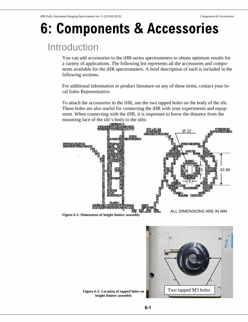
iHR Fully Automated Imaging Spectrometer rev. G (28 Feb 2012) Components & Accessories
6-1
6: Components & Accessories Introduction
You can add accessories to the iHR-series spectrometers to obtain optimum results for
a variety of applications. The following list represents all the accessories and compo-
nents available for the iHR spectrometers. A brief description of each is included in the
following sections.
For additional information or product literature on any of these items, contact your lo-
cal Sales Representative.
To attach the accessories to the iHR, use the two tapped holes on the body of the slit.
These holes are also useful for connecting the iHR with your experiments and equip-
ment. When connecting with the iHR, it is important to know the distance from the
mounting face of the slit’s body to the slits:
Figure 6-1: Dimensions of height-limiter assembly
Two tapped M3 holes
42.66
Ø 22
ALL DIMENSIONS ARE IN MM
15
8
Figure 6-2: Location of tapped holes on
height-limiter assembly
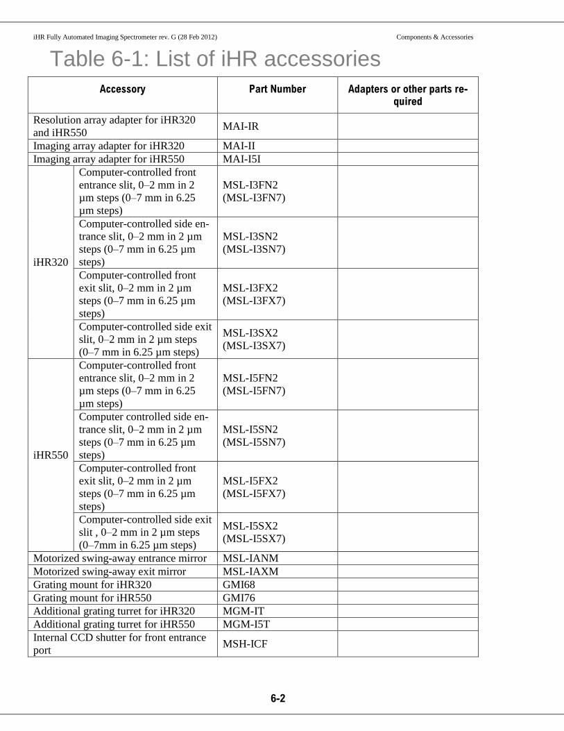
iHR Fully Automated Imaging Spectrometer rev. G (28 Feb 2012) Components & Accessories
6-2
Table 6-1: List of iHR accessories
Accessory Part Number Adapters or other parts re-quired
Resolution array adapter for iHR320
and iHR550 MAI-IR
Imaging array adapter for iHR320 MAI-II
Imaging array adapter for iHR550 MAI-I5I
iHR320
Computer-controlled front
entrance slit, 0–2 mm in 2
µm steps (0–7 mm in 6.25
µm steps)
MSL-I3FN2
(MSL-I3FN7)
Computer-controlled side en-
trance slit, 0–2 mm in 2 µm
steps (0–7 mm in 6.25 µm
steps)
MSL-I3SN2
(MSL-I3SN7)
Computer-controlled front
exit slit, 0–2 mm in 2 µm
steps (0–7 mm in 6.25 µm
steps)
MSL-I3FX2
(MSL-I3FX7)
Computer-controlled side exit
slit, 0–2 mm in 2 µm steps
(0–7 mm in 6.25 µm steps)
MSL-I3SX2
(MSL-I3SX7)
iHR550
Computer-controlled front
entrance slit, 0–2 mm in 2
µm steps (0–7 mm in 6.25
µm steps)
MSL-I5FN2
(MSL-I5FN7)
Computer controlled side en-
trance slit, 0–2 mm in 2 µm
steps (0–7 mm in 6.25 µm
steps)
MSL-I5SN2
(MSL-I5SN7)
Computer-controlled front
exit slit, 0–2 mm in 2 µm
steps (0–7 mm in 6.25 µm
steps)
MSL-I5FX2
(MSL-I5FX7)
Computer-controlled side exit
slit , 0–2 mm in 2 µm steps
(0–7mm in 6.25 µm steps)
MSL-I5SX2
(MSL-I5SX7)
Motorized swing-away entrance mirror MSL-IANM
Motorized swing-away exit mirror MSL-IAXM
Grating mount for iHR320 GMI68
Grating mount for iHR550 GMI76
Additional grating turret for iHR320 MGM-IT
Additional grating turret for iHR550 MGM-I5T
Internal CCD shutter for front entrance
port MSH-ICF
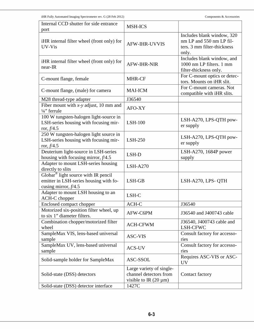
iHR Fully Automated Imaging Spectrometer rev. G (28 Feb 2012) Components & Accessories
6-3
Internal CCD shutter for side entrance
port MSH-ICS
iHR internal filter wheel (front only) for
UV-Vis AFW-IHR-UVVIS
Includes blank window, 320
nm LP and 550 nm LP fil-
ters. 3 mm filter-thickness
only.
iHR internal filter wheel (front only) for
near-IR AFW-IHR-NIR
Includes blank window, and
1000 nm LP filters. 1 mm
filter-thickness only.
C-mount flange, female MHR-CF For C-mount optics or detec-
tors. Mounts on iHR slit.
C-mount flange, (male) for camera MAI-ICM For C-mount cameras. Not
compatible with iHR slits.
M28 thread-type adapter J36540
Fiber mount with x-y adjust, 10 mm and
¼″ ferrule AFO-XY
100 W tungsten-halogen light-source in
LSH-series housing with focusing mir-
ror, f/4.5
LSH-100 LSH-A270, LPS-QTH pow-
er supply
250 W tungsten-halogen light source in
LSH-series housing with focusing mir-
ror, f/4.5
LSH-250 LSH-A270, LPS-QTH pow-
er supply
Deuterium light-source in LSH-series
housing with focusing mirror, f/4.5 LSH-D
LSH-A270, 1684P power
supply
Adapter to mount LSH-series housing
directly to slits LSH-A270
Globar® light source with IR pencil
emitter in LSH-series housing with fo-
cusing mirror, f/4.5
LSH-GB LSH-A270, LPS- QTH
Adapter to mount LSH housing to an
ACH-C chopper LSH-C
Enclosed compact chopper ACH-C J36540
Motorized six-position filter wheel, up
to six 1″ diameter filters. AFW-C6PM J36540 and J400743 cable
Combination chopper/motorized filter
wheel ACH-CFWM
J36540, J400743 cable and
LSH-CFWC
SampleMax VIS, lens-based universal
sample ASC-VIS
Consult factory for accesso-
ries
SampleMax UV, lens-based universal
sample ACS-UV
Consult factory for accesso-
ries
Solid-sample holder for SampleMax ASC-SSOL Requires ASC-VIS or ASC-
UV
Solid-state (DSS) detectors
Large variety of single-
channel detectors from
visible to IR (20 µm)
Contact factory
Solid-state (DSS) detector interface 1427C

iHR Fully Automated Imaging Spectrometer rev. G (28 Feb 2012) Components & Accessories
6-4
PMT detectors 1911F, 1914F (200–850
nm) and others Contact factory
450 W Xe light-source FL-1039
iHR320: J355597-front or
side
iHR550: J355617-front or
side
Fiber-coupler with f/# matching optics
(lenses) for SMA and ferrule 220F 220F-AFC available for FC
Fiber-coupler for 10 mm and 0.25″ fer-
rule with x-y adjust, no optics AFO-XY
Fiber-coupler, mirror-based, for 10 mm
ferrule J23078640
Consult factor for SMA and
FC adapters
Simple fiber-adapter for 0.25″ ferrule 120F
Before removal of four mounting screws
After removal of four mounting screws
Figure 6-3: Removal of height-limiter assembly
Note: Certain custom accessories require removal of the height-limiter assembly in order to be attached to the iHR chassis. To remove the height-limiter assembly, remove the four screws holding the assembly onto the chassis.

iHR Fully Automated Imaging Spectrometer rev. G (28 Feb 2012) Components & Accessories
6-5
Female C-mount Adapter MHR-CF When attached to the slit assembly, this C-mount adapter provides a mounting surface
with the standard female C-mount thread. To attach the MHR-CF, place the C-mount
adapter against the slit assembly and use four M3 × 10 mm flat-head screws to attach
the adapter to the slit as shown below.
Figure 6-4: Attaching MHR-CF adapter to height-limiter assembly

iHR Fully Automated Imaging Spectrometer rev. G (28 Feb 2012) Components & Accessories
6-6
Male C-mount Adapter MAI-ICM Male C-mount adapter for IHR spectrometers. Requires female threads on camera. The
male C-mount adapter allows coupling of any camera with a C-mount interface to the
iHR. The MAI-ICM provides the standard male C-mount thread. To use this adapter:
1 Screw the MAI-ICM flange onto your camera.
2 Insert the flange into the iHR.
3 Slide the camera/flange assembly in or out of the exit port to focus the spectral output on the camera focal plane.
4 Rotate the camera/flange assembly to align the spectral output to the camera focal plane.
5 When the camera is properly aligned and fo-cused, use a 2.5 mm Allen key to tighten the flange lock and secure the camera in place.
Figure 6-5: Attaching MAI-ICM to iHR
MAI-ICM

iHR Fully Automated Imaging Spectrometer rev. G (28 Feb 2012) Components & Accessories
6-7
LSH Series Lamp Housings
Figure 6-6: Attaching LSH to height-limiter assembly
1 Mount the LSH-A270 adapter to the LSH lamp housing (LSH-250, LSH-100, or LSH-GB) using two M3 × 10 mm cap-head screws.
2 Mount the LSH lamp housing, via the LSH-A270 adapter, to the iHR
slit assembly using two M3 × 10
mm cap-head screws.
Figure 6-7: LSH-A270
adapter
Figure 6-8: LSH-series lamp housing

iHR Fully Automated Imaging Spectrometer rev. G (28 Feb 2012) Components & Accessories
6-8
SampleMax
1 Remove the SampleMax sample compartment cover to gain access to the four screws that se-cure the mounting adapter to the wall of the sample compartment.
2 Remove the mounting adapter.
3 Using two M3 × 10 mm cap-head screws, se-cure the Mounting Adapter to the iHR slit as-sembly.
4 Using the four screws previously removed, re-secure the Mounting Adapter to the SampleMax.
Figure 6-9: SampleMax attached to iHR

iHR Fully Automated Imaging Spectrometer rev. G (28 Feb 2012) Components & Accessories
6-9
ACH-C Optical Chopper The M28 adapter (MHR-M28) is a required accessory for mounting the chopper head
to the spectrometer slit.
1 Mount the M28 adapter to your spectrometer slit assembly if it has not yet been mounted.
2 Screw the chopper head to the M28 adapter of your spectrometer using the M28 knurled nut at-tached to the chopper cover.

iHR Fully Automated Imaging Spectrometer rev. G (28 Feb 2012) Components & Accessories
6-10
1427C Detector Housing
Figure 6-10: Schematic of 1427C with support leg
1 Remove protective cover from the exit-slit.
2 Using a 7/64″ hex key, remove the four screws on the front of the housing, and remove the front end of the housing.
3 Place the front part of housing against entrance-slit housing, so that two mounting holes are
Note: The housing must be partially disassembled to allow two 6-32″ mounting screws to pass though the flange.
Figure 6-11: Removing front end of housing
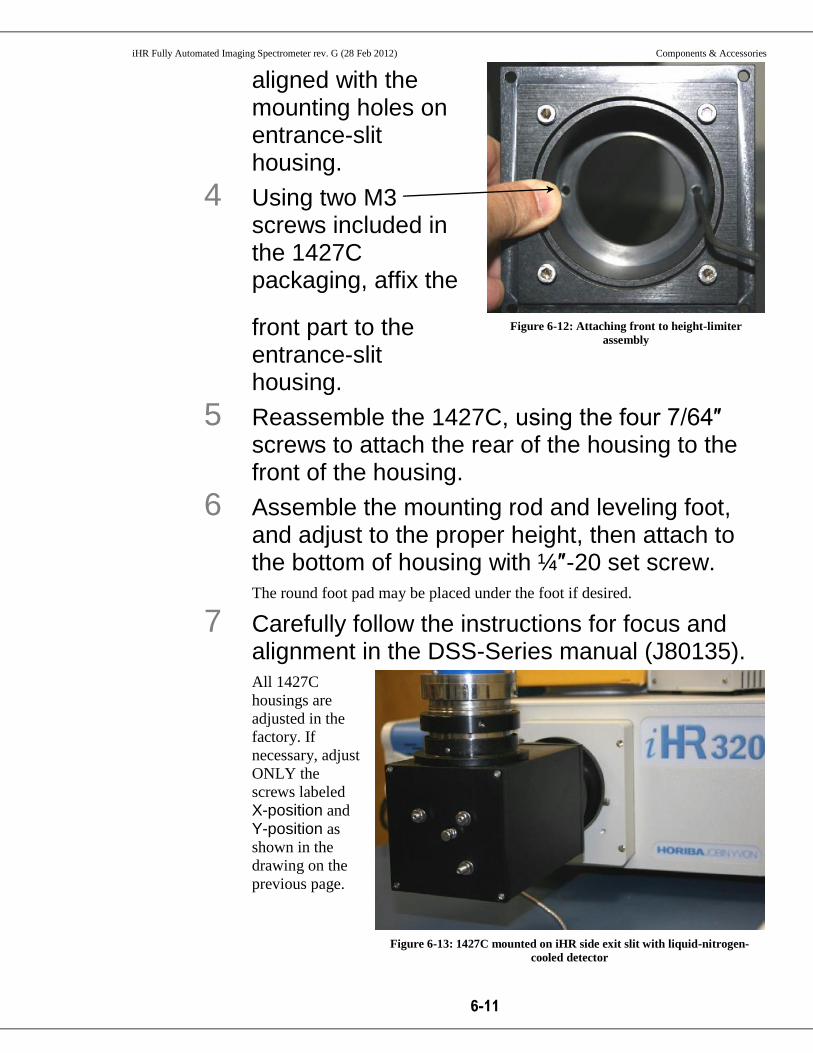
iHR Fully Automated Imaging Spectrometer rev. G (28 Feb 2012) Components & Accessories
6-11
aligned with the mounting holes on entrance-slit housing.
4 Using two M3 screws included in the 1427C packaging, affix the
front part to the entrance-slit housing.
5 Reassemble the 1427C, using the four 7/64″ screws to attach the rear of the housing to the front of the housing.
6 Assemble the mounting rod and leveling foot, and adjust to the proper height, then attach to the bottom of housing with ¼″-20 set screw. The round foot pad may be placed under the foot if desired.
7 Carefully follow the instructions for focus and alignment in the DSS-Series manual (J80135). All 1427C
housings are
adjusted in the
factory. If
necessary, adjust
ONLY the
screws labeled
X-position and
Y-position as
shown in the
drawing on the
previous page.
Figure 6-12: Attaching front to height-limiter
assembly
Figure 6-13: 1427C mounted on iHR side exit slit with liquid-nitrogen-
cooled detector

iHR Fully Automated Imaging Spectrometer rev. G (28 Feb 2012) Components & Accessories
6-12
220F Fiber Adapters Introduction
The 220F fiber-optic adapter kit is designed for use with iHR, MicroHR, and FHR Se-
ries spectrometers, and contains 60 mm and 40 mm focal-length lenses. All kits include
a centering mount which allows lateral and vertical adjustment, plus rotation of fiber
position. When the adapter is mounted to an instrument slit, use the lenses to match the
fiber-optic aperture to the instrument aperture. This lets you use the entire fiber-optic
aperture and reduces stray light. These adapters were designed for use with optical fi-
ber-optics with N.A. = 0.22 (f/2.3).
Installation
1 Remove Fiber Adapter from packaging and in-spect for damage.
2 Open sliding cover and remove plastic bags containing tools, screws, and fiber-insert.
3 Choose the type of termination of your fiber-optics and attach it to the centering mount:
a For SMA termination, choose the SMA fiber-insert, place inside the
centering mount, and use the small screwdriver to secure by tightening four
set screws on the centering mount.
b For FC/PC termination, 220F-AFC is required (not included in the 220F
basic package). Choose the 220F-AFC, place inside the centering mount,
and use the small screwdriver to secure insert by tightening four set screws
on the centering mount.
c For ¼″-ferrule termination, first insert the end of the fiber-optic through the
back flange of the Fiber Adapter, then insert the ferrule into the fiber-insert.
Using a 0.05″ Allen key, secure the fiber by tightening the 4-40 set screw.
Place the fiber-insert inside the centering mount, and use the small
screwdriver to secure the insert by tightening four set screws on the
centering mount.
4 To mount the Fiber Adapter on a monochromator, place front on entrance slit, line up the mounting holes, and secure in position using two cap-head mounting screws Use M3 with 2.5 mm Allen key for iHR and metric spectrometers; 8-32 with
5/64″ Allen key for TRIAX. Figure 1 shows a 220F fiber adapter mounted on an
iHR320 spectrometer.

iHR Fully Automated Imaging Spectrometer rev. G (28 Feb 2012) Components & Accessories
6-13
Figure 6-14: 220F fiber-adapter mounted on iHR320
5 Make sure that the two plano-convex lenses are facing each other.
Fiber-optic alignment and optimization
1 Check that all detector high-voltage is off.
2 Remove the instrument cover and illuminate the fiber with a visible light source. Set the slit-width to its working width (no less than 100 µm).
3 Turn off the room lights.
4 Adjust the lens closest to the monochromator (Lens 2 – See Figure 3) so that the distance be-tween it and the slit is equal to its focal length. This distance is 60 mm for the 220F.
5 Adjust the lens clos-est to the fiber-optic and the light source (Lens 1) so that the distance between the fiber-optic tip and lens is equal to
Lens 2 = 60 mm
Lens 1 = 40 mm
Centering Mount
Monochromator
Figure 6-15: Interior of 220F with optics

iHR Fully Automated Imaging Spectrometer rev. G (28 Feb 2012) Components & Accessories
6-14
its focal length. Continue to adjust this pair until the grating is fully illuminated. Test the grating illumination by placing a white screen (such as a piece of paper
or business card) in front of the grating. The full area of the grating should be il-
luminated. If the grating is not fully illuminated or if an area outside of the grat-
ing is illuminated, continue to adjust the lens.
6 Check to see that the light is centered by plac-ing the screen between the entrance slit and the first active optic. You should observe a circular, homogeneously illuminated area. If the image
appears disproportionate or is only partially displayed, then the light is not cen-
tered. Center the fiber using the lateral adjustment screws of the centering
mount, and continue to observe the screen until the proper image is obtained.
7 To verify that light is horizontally centered, re-duce the slit to its minimum width. If the top and bottom of the image appear symmetrical on the screen, then the light is approximately centered. If the image appears asymmetrical, then the light is not centered. Center the fi-
ber using the vertical adjustment screws of the centering mount, and continue to
observe until the proper image is obtained.
8 Replace the instrument cover.
9 Connect the fiber-optic to the experiment, and turn on the detector.
10 Optimize positions to get the best signal (any changes in position should be minimal).
11 Close the adapter housing and restore room lights. Typical distances d from the slit are: dLens2 = 60 mm, dLens1 =100 mm, dfiber =
140 mm.
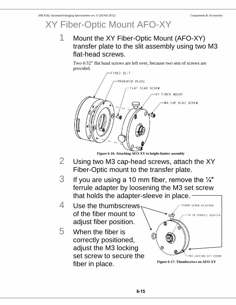
iHR Fully Automated Imaging Spectrometer rev. G (28 Feb 2012) Components & Accessories
6-15
XY Fiber-Optic Mount AFO-XY
1 Mount the XY Fiber-Optic Mount (AFO-XY) transfer plate to the slit assembly using two M3 flat-head screws. Two 6/32″ flat head screws are left over, because two sets of screws are
provided.
Figure 6-16: Attaching AFO-XY to height-limiter assembly
2 Using two M3 cap-head screws, attach the XY Fiber-Optic mount to the transfer plate.
3 If you are using a 10 mm fiber, remove the ¼″ ferrule adapter by loosening the M3 set screw that holds the adapter-sleeve in place.
4 Use the thumbscrews of the fiber mount to adjust fiber position.
5 When the fiber is correctly positioned, adjust the M3 locking set screw to secure the fiber in place.
Figure 6-17: Thumbscrews on AFO-XY

iHR Fully Automated Imaging Spectrometer rev. G (28 Feb 2012) Components & Accessories
6-16
CCD Flange to CCD Introduction
The CCD imaging flange for iHR320 (MAI-II) and for iHR550 (MAI-I5I), and
resolution flange (MAI-IR), are all designed to attach to HORIBA Scientific CCD
cameras. To accommodate other CCD cameras, please contact the HORIBA Scientific
Sales Department.
MAI-IR flange to a HORIBA Scientific camera:
Figure 6-18: Schematic of MAI-IR flange
1 Place the CCD flange over the end of the camera and rotate it so that the rectangular mask on the CCD flange is square to the camera body, and the three tapped holes in the camera face line up with the three counterbored holes on the CCD flange. The alignment pin should be at the top.
2 Attach the flange to the camera using three 3/8″ long 8/32 flat-head screws.
3 See Chapter 1: Installation of the CCD Camera for installation instructions.

iHR Fully Automated Imaging Spectrometer rev. G (28 Feb 2012) Components & Accessories
6-17
MAI-II or MAI-I5I flange to a HORIBA Scientific cam-era:
Figure 6-19: Schematic of MAI-II flange

iHR Fully Automated Imaging Spectrometer rev. G (28 Feb 2012) Components & Accessories
6-18
Figure 6-20: Schematic of MAI-I5I flange
1 Place the CCD flange over the end of the cam-era and rotate it so that the rectangular mask on the CCD flange is square to the camera body and the alignment pin is at the top. Two tapped holes in the camera face line up with counterbored holes on the
CCD flange, at the bottom, and upper right.
2 Attach the flange to the camera using two 3/8″ long 8/32 flat-head screws.
3 See Chapter 3: Installation of the CCD Camera for installation instructions.

iHR Fully Automated Imaging Spectrometer rev. G (28 Feb 2012) Components & Accessories
6-19
Shutter Shutter-replacement procedure
1 Remove the top cover. Loosen and remove the nine M3 cap-head screws on the top cover.
2 Remove the baffle cover.
d If the unit has side entrance or exit fold mirrors, set the mirrors for front
entrance and exit operation via software.
The mirrors now lie against the sides of the housing.
e Remove the two M3 cap-head screws and two Phillips-head screws that
secure the cover.
f Now carefully lift the baffle cover out of the spectrometer housing.
You must rotate the cover slightly to do this.
3 Remove the old CCD shutter.
a If you are replacing the side entrance shutter, you must first command
the entrance fold mirror for side entrance operation.
This moves the mirror away from the side wall allowing access to the
shutter.
b Power the system down.
c Trace the shutter cable back to the electronic connector board.
Note the location of the shutter cable. You will need to know where to
plug in the new shutter.
d Unplug the shutter cable.
e Loosen the two M3 cap-head screws that secure the shutter assembly.
f Remove the shutter assembly.
4 Install the new shutter assembly.
a For a front-entrance
slit, place the new
front-entrance shutter
assembly on the front-
entrance slit.
Figure 6-21: Shutter mount for front en-
trance on iHR

iHR Fully Automated Imaging Spectrometer rev. G (28 Feb 2012) Components & Accessories
6-20
b For a side-entrance
slit, place the new
slide-entrance shutter
assembly against the
side-entrance wall so
that the mounting
holes on the
mounting plate line
up with the tapped
holes on the side wall
of the housing.
c Install the two M3
cap-head screws in the new shutter assembly and tighten them to secure
the shutter in place.
d Dress the cable along the bottom of the unit.
e Plug the shutter connector into the appropriate location on the
electronics connector board.
If you are not sure of the correct location, there is a connector diagram
on the back of the baffle cover which indicates the correct location for
the shutter.
5 Replace the baffle cover.
6 Replace the top cover.
Figure 6-22: Shutter mount for side entrance on iHR

iHR Fully Automated Imaging Spectrometer rev. G (28 Feb 2012) Components & Accessories
6-21
Internal Filter Wheel Filter-wheel operation
The iHR offers both internal and external filter wheel options. The internal filter wheel
option for the iHR holds up to six one-inch (25 mm) circular filters. Filter selection is
computer-controlled. The internal filter wheel and filters must be purchased with the
system. (An internal glass filter introduces a slight shift in focus, so the all of the filters
used must have the same thickness.)
HORIBA Scientific offers a standard set of cut-on filters. There are two options for fil-
ter-sets:
Table 6-2: AFW-IHR-UVVIS (nominal 3 mm filter-thickness) UV-S1 window J50311
LP-320nm J650500
LP-550nm J650501
Optional (to be ordered as separate line item)
LP-385nm LPF-CG385
LP-630nm J50449
LP-830nm J50451
LP-850nm J650514
1 micron long pass LPF-D1-0-3MM
Table 6-3: AFW-IHR-NIR (nominal 1 mm filter-thickness) UV-S1 window J50336
1 micron long pass LPF-D1-0
Optional (to be ordered as separate line item)
1.9 micron long pass LPF-D1-9
3.5 micron long pass LPF-D3-5
6.0 micron long pass LPF-D6-0
11.7 micron long pass LPF-D11-7
You may install additional filters of the correct thickness.
Filter installation
1 Remove the top cover. Loosen and remove the nine M3 cap-head screws on the top cover.
Note: The presence of internal filters can also produce a slight shift in wavelength. This wavelength error can be removed by following the wavelength-calibration procedure.

iHR Fully Automated Imaging Spectrometer rev. G (28 Feb 2012) Components & Accessories
6-22
2 Remove the filter wheel from the filter-wheel motor shaft.
a If your system has
a CCD shutter on
the entrance slit,
you first need to
temporarily
remove the shutter
assembly from the
entrance slit to
make room for the
removal of the
filter wheel.
To do this, loosen
the two M3 set
screws on the top
of the shutter block
assembly and lift
the shutter
assembly up out of the way. You do not need to disconnect the shutter
cable to do this.
b The filter wheel is secured to the motor shaft with two M3 set screws.
Loosen these two set screws.
If necessary, gently rotate the filter wheel by hand to gain access to the
screw holes.
c Slide the filter wheel off of the shaft and remove it from the unit.
3 Install new filters.
a Locate the desired filter-hole
location and remove the retaining
ring from the hole.
b Insert the new filter into the hole and
press the retaining ring in behind it
to secure it in position.
To avoid touching the filter, use lens
tissue to press in the retaining ring.
Be sure the retaining ring in pressed
all the way in so that the filter is not
loose.
4 Replace the filter wheel back on the filter-wheel motor shaft.
Figure 6-23: Removing filter wheel
Figure 6-24: Schematic of filter wheel

iHR Fully Automated Imaging Spectrometer rev. G (28 Feb 2012) Components & Accessories
6-23
a Slide the filter wheel back onto the motor shaft.
The beveled face of the wheel should face away from the entrance slit.
b Tighten the two M3 set screws to secure the filter wheel to the motor
shaft.
5 Replace the top cover.

iHR Fully Automated Imaging Spectrometer rev. G (28 Feb 2012) Components & Accessories
6-24
Assembling LSH + ACH-C + SampleMax + iHR320
1 Insert the two 6-32 cap-head screws into the through-holes in the LSH-C and mount to two threaded holes on the flat side of ACH-H. Typically these two parts are shipped already
mounted together.
2 Remove the slit cover from the iHR entrance slit.
3 Using the M3 screws removed from the slit cov-er, mount the SampleMax ring (J350386) to the entrance slit.
4 Remove the SampleMax cover.
5 Place the four 8-32 mounting screws on the front interior wall of the SampleMax, and tighten them to attach to the SampleMax ring.
6 Place two pads under the rear two feet of the SampleMax, and adjust the height so the height of the SampleMax matches the spectrometer height.
Figure 6-25: LSH-C attached to
ACH-H
Figure 6-26: SampleMax ring mounted on iHR

iHR Fully Automated Imaging Spectrometer rev. G (28 Feb 2012) Components & Accessories
6-25
7 Using two 6-32 screws, mount the M28 male adapter (J36540) to the ring on the back of the SampleMax.
8 Connect the ACH-C to the SampleMax via M28 adapters.
9 Remove the cover to the LSH housing.
10 Insert the lower large screws into the slots on the front plate.
11 Place the two Phillips-head screws on the in-side of the LSH front plate, and mount to the LSH-C.
12 Attach the support screw and pad to the rear underside of the LSH housing.
13 As per the instructions in the LSH manual, ad-just the mirror so that the light is centered on the exit, and the spot is centered on the sample holder in the SampleMax.
Figure 6-27: ACH-C connected with M28 adapters
Figure 6-28: Interior of LSH housing

iHR Fully Automated Imaging Spectrometer rev. G (28 Feb 2012) Components & Accessories
6-26
14 Follow the instructions in the operation manual for each component to finish setting up the sys-tem.
Figure 6-29: Example of complete system consisting of LSH-T250 + LSH-C + ACH-C + SampleMax + iHR320

iHR Fully Automated Imaging Spectrometer rev. G (28 Feb 2013) Service Information
7-1
7 : Service Information Service policy
If you need assistance in resolving a problem with your instrument, contact our Cus-
tomer Service Department directly, or if outside the United States, through our repre-
sentative or affiliate covering your location.
Often it is possible to correct, reduce, or localize the problem through discussion with
our Customer Service Engineers.
All instruments are covered by warranty. The warranty statement is printed on the in-
side back cover of this manual. Service for out-of-warranty instruments is also availa-
ble, for a fee. Contact HORIBA Instruments Incorporated or your local representative
for details and cost estimates.
If your problem relates to software, please verify your computer's operation by running
any diagnostic routines that were provided with it. Please refer to the software docu-
mentation for troubleshooting procedures. If you must call for Technical Support,
please be ready to provide the software serial number, as well as the software version
and firmware version of any controller or interface options in your system. The soft-
ware version can be determined by selecting the software name at the right end of the
menu bar and clicking on “About.” Also knowing the memory type and allocation, and
other computer hardware configuration data from the PC’s CMOS Setup utility may be
useful.
In the United States, customers may contact the Customer Service department directly.
From other locations worldwide, contact the representative or affiliate for your loca-
tion.
In the USA: HORIBA Instruments Incorpo-
rated
3880 Park Avenue
Edison, New Jersey 08820
USA
Tel: +1-732-494-8660 Ext. 160
Fax: +1-732-494-9796
Email:
In France: Jobin Yvon SAS
16-18 rue du Canal
91165 Longjumeau
Cedex
France
Tel: +33 (0) 1 64 54
13 00
Fax: +33 (0) 1 69 09
93 19
Worldwide: 1-877-
546-7422 China: +86 (0) 10 6849
2216
Germany: +49 (0) 89
462317-15
Italy: +39 (0) 2 57603050
Japan: +81 (0) 3 58230141
UK: +44 (0) 20 8204 8142
If an instrument or component must be returned, the method described on the following
page should be followed to expedite servicing and reduce your downtime.

iHR Fully Automated Imaging Spectrometer rev. G (28 Feb 2013) Service Information
7-2
Return authorization All instruments and components returned to the factory must be accompanied by a Re-
turn Authorization Number issued by our Customer Service Department.
To issue a Return Authorization number, we require:
The model and serial number of the instrument
A list of items and/or components to be returned
A description of the problem, including operating settings
The instrument user's name, mailing address, telephone, and fax numbers
The shipping address for shipment of the instrument to you after service
Your Purchase Order number and billing information for non-warranty services
Our original Sales Order number, if known
Your Customer Account number, if known
Any special instructions

iHR Fully Automated Imaging Spectrometer rev. G (28 Feb 2013) Service Information
7-3
Warranty For any item sold by Seller to Buyer or any repair or service, Seller agrees to repair or
replace, without charge to Buyer for labor or materials or workmanship of which Seller
is notified in writing before the end of the applicable period set forth below, beginning
from the date of shipment or completion of service or repair, whichever is applicable:
a. New equipment, product and laboratory apparatus: 1 year with the following
exceptions:
i. Computers and their peripherals
ii. Glassware and glass products.
b. Repairs, replacements, or parts – the greater of 30 days and the remaining origi-
nal warranty period for the item that was repaired or replaced.
c. Installation services – 90 days.
The above warranties do not cover components manufactured by others and which are
separately warranted by the manufacturer. Seller shall cooperate with Buyer in obtain-
ing the benefits of warranties by manufacturers of such items but assumes no obliga-
tions with respect thereto.
All defective items replaced pursuant to the above warranty become the property of
Seller.
This warranty shall not apply to any components subjected to misuse due to common
negligence, adverse environmental conditions, or accident, nor to any components
which are not operated in accordance with the printed instructions in the operations
manual. Labor, materials and expenses shall be billed to the Buyer at the rates then in
effect for any repairs or replacements not covered by this warranty.
This warranty shall not apply to any HORIBA Instruments Incorporated manufactured
components that have been repaired, altered or installed by anyone not authorized by
HORIBA Instruments Incorporated in writing.
THE ABOVE WARRANTIES AND ANY OTHER WARRANTIES SET FORTH IN
WRITING HERIN ARE IN LIEU OF ALL OTHER WARRANTIES OR GUARAN-
TEES EXPRESSED OR IMPLIED, INCLUDING WARRANTIES OF MERCHANT-
ABILITY, FITNESS FOR PURPOSE OR OTHER WARRANTIES.
The above shall constitute complete fulfillment of all liabilities of Seller, and Seller
shall not be liable under any circumstances for special or consequential damages, in-
cluding without limitation loss of profits or time or personal injury caused.
The limitation on consequential damages set forth above is intended to apply to all as-
pects of this contract including without limitation Seller’s obligations under these
standard terms.

iHR Fully Automated Imaging Spectrometer rev. G (28 Feb 2013) Service Information
7-4
Notes

iHR Fully Automated Imaging Spectrometer rev. G (28 Feb 2013) Compliance Information
8-1
8: Compliance Information Declaration of Conformity
Manufacturer: HORIBA Instruments Incorporated.
Address: 3880 Park Avenue
Edison, NJ 08820
USA
Product Name: iHR Imaging Spectrometer
Model Names:
Product Op-
tions:
iHR320, iHR550
All options and customized products based on
the above.
Conforms to the following Standards:
Safety: EN 61010-1: 2001
EN 61010-1: 2001/AC: 2002
EMC: EN 61326-1: 2006 (Emissions & Immunity)
Supplementary Information The product herewith complies with the requirements of the Low Voltage Directive
2006/95/EC and the EMC Directive 2004/108/EC.
The CE marking has been affixed on the device according to Article 8 of the EMC Di-
rective 2004/108/EC.
The technical file and documentation are on file with HORIBA Instruments Incorpo-
rated.
_____________________________
Salvatore H. Atzeni, Ph.D.
Vice-President, Retail Engineering, and CTO
HORIBA Instruments Incorporated
Edison, NJ 08820
USA
October 7, 2011

iHR Fully Automated Imaging Spectrometer rev. G (28 Feb 2013) Compliance Information
8-2
Applicable CE Compliance Tests and Standards
Test Standards
Emissions, Radiated/Conducted EN 55011: 2006
Radiated Immunity IEC 61000-4-3: 2006
Conducted Immunity IEC 61000-4-6: 2008
Electrical Fast Transients IEC 61000-4-4: 2004
Electrostatic Discharge IEC 61000-4-2: 2008
Voltage Interruptions IEC 61000-4-11: 2004
Surge Immunity IEC 61000-4-5: 2005
Magnetic Field Immunity IEC 61000-4-8: 2009
Harmonics IEC 61000-3-2: 2006
Flicker IEC 61000-3-3: 2008
Safety EN 61010-1: 2001
EN 61010-1: 2001/AC: 2002

iHR Fully Automated Imaging Spectrometer rev. G (28 Feb 2013) Index
9-1
9: Index Key to the entries:
Times New Roman font ......... subject or
keyword
Arial font ................................ command,
menu choice,
or data-entry
field
Arial Condensed Bold font ..... dialog box
Courier New font ......... file name or
extension
1
120F ...........................................................6-4
1427C ......................................... 6-4, 6-10–11
1684P .........................................................6-3
1911F .........................................................6-4
1914F .........................................................6-4
2
220F ........................................... 6-4, 6-12–13
220F-AFC ................................................6-12
A
Accessory information .......................... 2-11
ACH-C ................................ 6-3, 6-9, 6-24–26
ACH-CFWM .............................................6-3
ACH-H .....................................................6-24
ACS-UV.....................................................6-3
actuator..................................................... 2-22
Add button ................................................. 2-9
AFO-XY ...................................... 6-3–4, 6-15
AFW-C6PM ...............................................6-3
AFW-IHR ..................................................3-5
AFW-IHR-NIR ................................ 6-3, 6-21
AFW-IHR-UVVIS ........................... 6-3, 6-21
Allen key ....................1-9, 2-24–25, 6-6, 6-12
array resolution ..........................................3-1
Apply button ............................................ 2-11
ASC-SSOL.................................................6-3
ASC-UV .................................................... 6-3
ASC-VIS ................................................... 6-3
Autorun .................................................... 1-15
B
backlash correction .................................... 2-6
baffle cover ........................................ 6-19–20
bandpass ......................................... 2-3, 3-3–4
BNC connection ........................................ 2-5
Browse button ........................................ 1-15
C
cables 1-6, 1-8, 1-15, 2-4–5, 2-26, 4-1–2, 6-3,
6-19–20, 6-22
Calibrate Grating… button ................... 2-16
Cancel button ......................................... 2-17
caution notice ............................................ 0-5
CCD ........................... 2-1–2, 2-16, 2-24, 2-25
CCD camera ............................................ 1-14
CCD detector ............................................. 1-8
CCD flange ................................. 2-2, 2-23–25
CCD flange lock ...................................... 2-24
CCD focus wheel............................... 2-24–25
CCD imaging flange ................................ 6-16
CCD Resolution Flange............................. 1-9
CCD rotation adjustment screw ........ 2-24–25
CCD shutter ................... 1-16, 6-3, 6-19, 6-22
CE compliance ........................................ 0-12
Choose Spectrometer drop-down list .. 2-8–
9, 2-11
chopper ............................................... 6-3, 6-9
C-mount adapter .................................... 6-5–6
C-mount flange .......................................... 6-3
Communications Type drop-down menu . 2-
10
ConfigTurret2.jyc ........................ 2-21
Configurations folder ...... 2-18, 2-20–21
Continue Anyway button ....................... 2-26
CSW-USB-SUPPORT-MONO ................. 2-2

iHR Fully Automated Imaging Spectrometer rev. G (28 Feb 2013) Index
9-2
D
danger to fingers notice..............................0-6
Declaration of Conformity .........................8-1
Detector Housing .....................................6-10
Device Display Name ........................... 2-10
Device Name list ..................................... 2-9
dimensions .................................................5-1
DIN connector.................................. 1-15, 4-1
disclaimer ...................................................0-3
Done button............................................. 2-17
Drive Correction Table tab ................... 2-15
DSS .............................................. 6-3–4, 6-11
DVD drive........................................ 1-5, 1-15
E
electric shock notice...................................0-5
electrical requirements ............................... 1-4
entrance port .................................... 2-1, 2-23
entrance slit ............................ 2-2–3, 2-14–15
environmental requirements ...................... 1-3
excessive humidity notice ..........................0-6
exit port ............................................ 2-2, 2-23
exit slit.............................................. 2-3, 2-14
extreme cold notice ....................................0-5
F
face-shield ............................................ 0-6 Fiber Adapter ............................. 6-4, 6-12–13
fiber-coupler...............................................6-4
fiber-optic adapter kit...............................6-12
Fiber-Optic Mount ........................... 6-3, 6-15
filter ............................................ 6-3, 6-21–22
filter wheel 2-5, 2-8, 2-11, 2-13, 2-15, 6-3, 6-
21–23
Filter Wheel tab ...................................... 2-15
Finish button.................................. 1-15, 2-27
firmware ..................................... 2-18–21, 4-1
FL-1039 .....................................................6-4
flange pin ................................................. 1-14
focus ........................................... 2-1, 2-24–25
focus-lock set screw ................................. 2-24
focus wheel .............................................. 1-14
Front ........................................................ 2-14
Front Entrance ....................................... 2-13
Front Exit ................................................ 2-13
G
Globar®
...................................................... 6-3
GMI68 ....................................................... 6-2
GMI76 ....................................................... 6-2
grating ... 1-6–8, 1-11–13, 2-1–2, 2-6–7, 2-13–
19, 3-1–2, 3-5, 4-2, 5-1–2, 6-2, 6-14
grating mount ............................................ 6-2
Grating tab ........................................ 2-15–16
grating turret ............................... 2-1, 2-7, 6-2
groove density ....................................... 3-1–2
H
height-limiter .......................... 2-15, 2-22, 5-2
height-limiter assembly . 6-1, 6-4–5, 6-7, 6-15
host computer ................... 2-18, 2-20–22, 4-1
hot equipment notice ................................. 0-6
I
imaging array adapter ................................ 6-2
InGaAs array ............................................. 2-2
Initialize button ................................ 2-8, 2-11
InstallShield Wizard dialog box .............. 1-15
intense light notice..................................... 0-5
J
J23078640 ................................................. 6-4
J350386 ................................................... 6-24
J351697 ..................................................... 1-9
J355597 ..................................................... 6-4
J355617 ..................................................... 6-4
J36540 .............................................. 6-3, 6-25
J50311 ..................................................... 6-21
J50336 ..................................................... 6-21
J50449 ..................................................... 6-21
J50451 ..................................................... 6-21
J650500 ................................................... 6-21
J650501 ................................................... 6-21
J650514 ................................................... 6-21
J81092 ....................................................... 1-9
J964007 .................................... 1-4, 1-9, 1-15

iHR Fully Automated Imaging Spectrometer rev. G (28 Feb 2013) Index
9-3
J980076 .................................................... 1-16
J980087 ...................................................... 1-9
J98015 ........................................................ 1-9
J98020 ........................................................ 1-9
J992024 ................................................ 1-9–10
J992029 ...................................................... 1-9
JYUSBMonoConfig window ..................... 2-19
L
LabVIEW™ VIs ........................................ 2-2
laser ............................................................ 2-3
laser diode .................................................. 2-3
Load Factory Configuration ................. 2-21
Load From… button ............................... 2-19
LPF-CG385 ..............................................6-21
LPF-D1-0 .................................................6-21
LPF-D1-0-3MM.......................................6-21
LPF-D11-7 ...............................................6-21
LPF-D1-9 .................................................6-21
LPF-D3-5 .................................................6-21
LPF-D6-0 .................................................6-21
LPS-QTH ...................................................6-3
LSH-100............................................. 6-3, 6-7
LSH-250............................................. 6-3, 6-7
LSH-A270 .......................................... 6-3, 6-7
LSH-C ........................................ 6-3, 6-24–26
LSH-CFWC ...............................................6-3
LSH-D ........................................................6-3
LSH-GB ............................................. 6-3, 6-7
LSH-series .................................................6-3
LSH-series housing ....................................6-3
M
M28 thread-type adapter ............................6-3
MAI-I5I ...................................... 6-2, 6-16–18
MAI-ICM ........................................... 6-3, 6-6
MAI-II ........................................ 6-2, 6-16–17
MAI-IR ..................................... 1-9, 6-2, 6-16
maintenance requirements ......................... 1-7
Material Safety Data Sheets .......................0-3
mercury lamp ........................................... 2-15
Metric accessories kit................................. 1-9
MGM-I5T ..................................................6-2
MGM-IT ....................................................6-2
MHR-CF ............................................ 6-3, 6-5
Mirrors area ............................................. 2-14
Mirrors tab ............................................... 2-15
Mono tab ................................................ 2-15
monochromator .......... 2-3, 2-14–15, 6-12–13
Mounting Adapter ..................................... 6-8
MSDS ........................................................ 0-3
MSH-ICF ................................................... 6-3
MSH-ICS ................................................... 6-3
MSL-I3FN2 ............................................... 6-2
MSL-I3FN7 ............................................... 6-2
MSL-I3FX2 ............................................... 6-2
MSL-I3FX7 ............................................... 6-2
MSL-I3SN2 ............................................... 6-2
MSL-I3SN7 ............................................... 6-2
MSL-I3SX2 ............................................... 6-2
MSL-I3SX7 ............................................... 6-2
MSL-I5FN2 ............................................... 6-2
MSL-I5FN7 ............................................... 6-2
MSL-I5FX2 ............................................... 6-2
MSL-I5FX7 ............................................... 6-2
MSL-I5SN2 ............................................... 6-2
MSL-I5SN7 ............................................... 6-2
MSL-I5SX2 ............................................... 6-2
MSL-I5SX7 ............................................... 6-2
MSL-IANM ............................................... 6-2
MSL-IAXM ............................................... 6-2
N
New Found Hardware Wizard window .... 2-26
Next > button .......... 1-15, 2-9–11, 2-17, 2-26
O
Observed radio button ........................... 2-17
OK button ............................... 2-8, 2-15, 2-27
Open button ............................................ 2-20
Open window ..................................... 2-19–20
order-sorting filter ..................................... 3-5
Other tab ................................................. 2-15
P
Pixels ...................................................... 2-16
PMT .................................................... 5-2, 6-4
power supply .............. 1-4, 1-9, 1-15, 4-1, 6-3
power switch............................................ 2-26

iHR Fully Automated Imaging Spectrometer rev. G (28 Feb 2013) Index
9-4
protective gloves ........................................0-6
R
read this manual notice ..............................0-6
relative humidity ........................................ 1-3
resolution array adapter .............................6-2
resolution flange ......................................6-16
Return Authorization Number ...................7-3
rotation adjustment ............................ 2-24–25
S
safety goggles ............................................0-6
safety requirements .................................... 1-6
safety summary ..........................................0-5
safety-training requirements ...................... 1-1
sample-holder............................................. 1-9
SampleMax ......................... 6-3, 6-8, 6-24–26
scan range ..................................................3-1
scan speed .................................................. 2-6
service policy .............................................7-1
Set button ................................................ 2-17
Setup.exe file ..................................... 1-15
shutter cable ............................................... 2-5
SHUTTER jack ....................................... 1-16
Side ......................................................... 2-14
Side Entrance ........................................ 2-13
Side Exit .................................................. 2-13
single-channel detector ............. 2-3, 2-16, 6-3
slit.. 4-2, 5-2, 6-1–3, 6-5, 6-7–15, 6-19–20, 6-
22–24
slit-width 2-3, 2-13, 2-15, 2-22, 3-1, 3-3–4, 5-
2, 6-13
Slits .......................................................... 2-13
Slits area .................................................. 2-13
Slits tab .................................................... 2-15
solid-state detector .................................6-3–4
spectral dispersion.............................. 3-1, 3-3
stepper motor ......................................... 2-6–7
stray light ......................................... 3-5, 6-12
surface requirements .................................. 1-2
swing-away entrance mirror ......................6-2
swing-away exit mirror ..............................6-2
SynerJY®
...................... 2-1–2, 2-8, 2-18, 2-21
SynerJY® Software Development Kit ....... 2-2
T
technical drawings ..................................... 5-3
technical specifications.............................. 5-1
tilt feet............................................... 1-8–1-10
TRIAX ..................................................... 6-12
troubleshooting .......................................... 4-1
turret ......................................... 2-18, 4-2, 5-1
turret cover ..................................... 1-11, 1-13
Turret 1 FirmWare ........................ 2-20
Turret 2 FirmWare ........................ 2-20
U
ultraviolet light notice 0-5
unpacking and installation ......................... 1-8
USB 2.0 hub ....................................... 1-5, 2-4
USB cable ......................................... 1-9, 1-16
USB Device Selection window ......... 2-8, 2-27
USB hub ........................................... 1-16, 2-4
USB Mono Config program .................... 2-13
USB port ................................... 1-5, 1-15, 4-1
USB Spectrometer Control program . 2-2, 2-8,
2-13
USB Spectrometer Utilities CD ................ 1-9
USB Spectrometer Utilities software ... 1-8, 1-
15, 2-18
USB SpectrometerConfig utility program ... 2-
19
W
warranty ..................................................... 7-4
Wavelength Control area ...................... 2-13
wavelength resolution....................... 2-6, 2-22
WaveLengths window ............................. 2-16
Windows® ......................................... 1-5, 1-15
Write button ............................................ 2-20

[Design Concept]
The HORIBA Group application images are collaged in the overall design.Beginning from a nano size element, the scale of the story develops all the way to the Earth with a gentle flow of the water.
3880 Park Avenue, Edison, New Jersey 08820-3012, USA
