yfm450far service manual - small engine discount · eb001000 notice this manual was produced by the...
TRANSCRIPT
LIT-11616-16-01 5ND-F8197-10
YFM450FAR
SERVICE MANUAL
Not For Resale www.SmallEngineDiscount.com

YFM450FARSERVICE MANUAL
©2002 by Yamaha Motor Corporation, U.S.A.First Edition, March 2002
All rights reserved. Any reproduction orunauthorized use without the written
permission of Yamaha Motor Corporation, U.S.A.is expressly prohibited.
Printed in U.S.A.LIT-11616-16-01
Not For Resale www.SmallEngineDiscount.com

EB001000
NOTICEThis manual was produced by the Yamaha Motor Company primarily for use by Yamaha dealersand their qualified mechanics. It is not possible to include all the knowledge of a mechanic in onemanual, so it is assumed that anyone who uses this book to perform maintenance and repairs onYamaha machine has a basic understanding of the mechanical ideas and the procedures ofmachine repair. Repairs attempted by anyone without this knowledge are likely to render themachine unsafe and unfit for use.
Yamaha Motor Company, Ltd. is continually striving to improve all its models. Modifications andsignificant changes in specifications or procedures will be forwarded to all authorized Yamahadealers and will appear in future editions of this manual where applicable.
NOTE:Designs and specifications are subject to change without notice.
IMPORTANT INFORMATIONParticularly important information is distinguished in this manual by the following notations.
The Safety Alert Symbol means ATTENTION! BECOME ALERT! YOURSAFETY IS INVOLVED!
Failure to follow WARNING instructions could result in severe injury or deathto the machine operator, a bystander or a person inspecting or repairing themachine.
A CAUTION indicates special precautions that must be taken to avoiddamage to the machine.
A NOTE provides key information to make procedures easier or clearer.
WARNING
CAUTION:
NOTE:
Not For Resale www.SmallEngineDiscount.com
EB002000
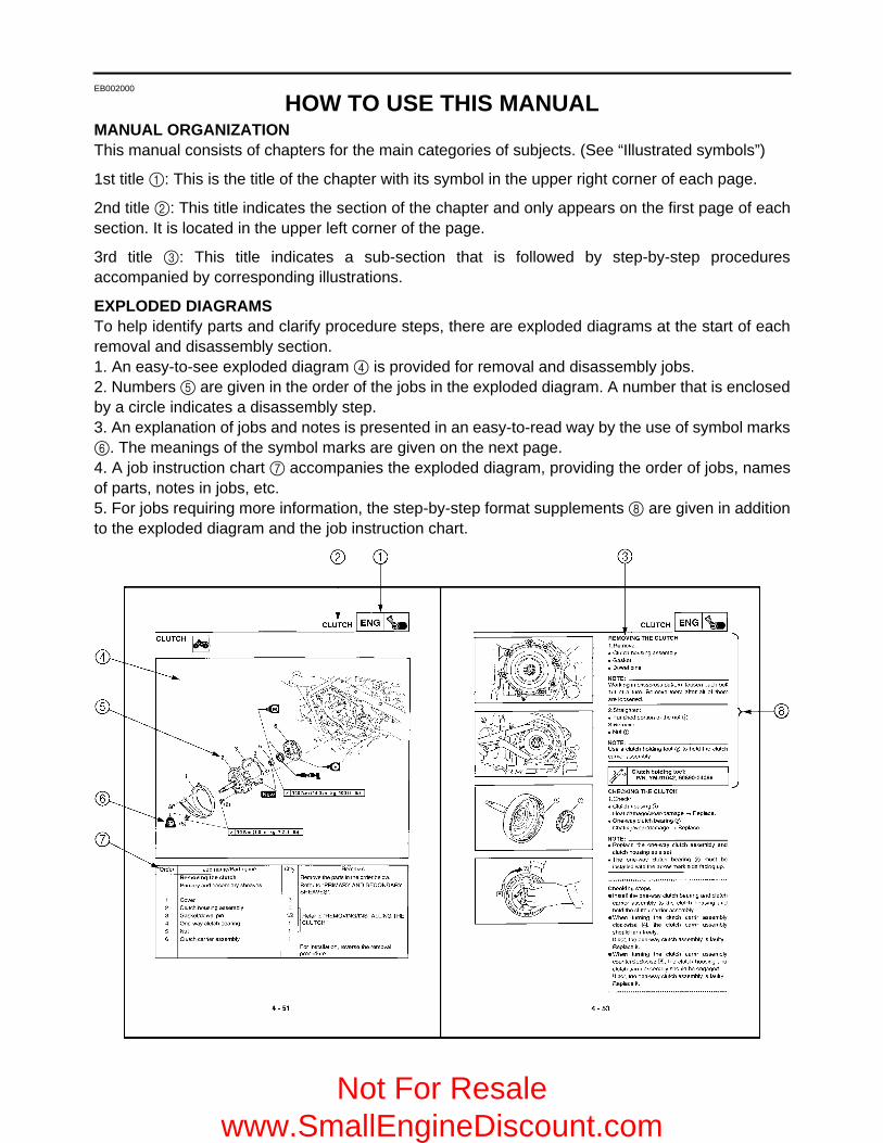
HOW TO USE THIS MANUALMANUAL ORGANIZATIONThis manual consists of chapters for the main categories of subjects. (See “Illustrated symbols”)
1st title 1: This is the title of the chapter with its symbol in the upper right corner of each page.
2nd title 2: This title indicates the section of the chapter and only appears on the first page of eachsection. It is located in the upper left corner of the page.
3rd title 3: This title indicates a sub-section that is followed by step-by-step proceduresaccompanied by corresponding illustrations.
EXPLODED DIAGRAMSTo help identify parts and clarify procedure steps, there are exploded diagrams at the start of eachremoval and disassembly section.1. An easy-to-see exploded diagram 4 is provided for removal and disassembly jobs.2. Numbers 5 are given in the order of the jobs in the exploded diagram. A number that is enclosedby a circle indicates a disassembly step.3. An explanation of jobs and notes is presented in an easy-to-read way by the use of symbol marks6. The meanings of the symbol marks are given on the next page.4. A job instruction chart 7 accompanies the exploded diagram, providing the order of jobs, namesof parts, notes in jobs, etc.5. For jobs requiring more information, the step-by-step format supplements 8 are given in additionto the exploded diagram and the job instruction chart.
Not For Resale www.SmallEngineDiscount.com
EB003000
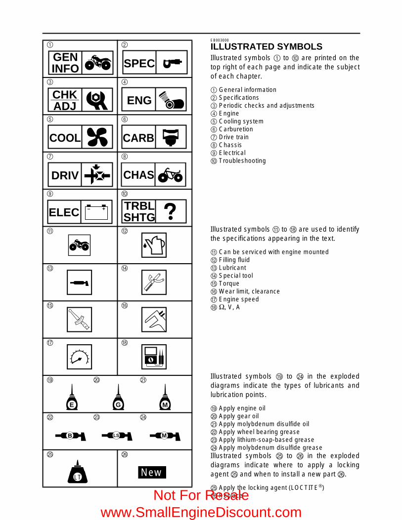
ILLUSTRATED SYMBOLSIllustrated symbols 1 to 0 are printed on thetop right of each page and indicate the subjectof each chapter.
1 General information2 Specifications3 Periodic checks and adjustments4 Engine5 Cooling system6 Carburetion7 Drive train8 Chassis9 Electrical0 Troubleshooting
Illustrated symbols A to H are used to identifythe specifications appearing in the text.
A Can be serviced with engine mountedB Filling fluidC LubricantD Special toolE TorqueF Wear limit, clearanceG Engine speedH Ω, V, A
Illustrated symbols I to N in the explodeddiagrams indicate the types of lubricants andlubrication points.
I Apply engine oilJ Apply gear oilK Apply molybdenum disulfide oilL Apply wheel bearing greaseM Apply lithium-soap-based greaseN Apply molybdenum disulfide greaseIllustrated symbols O to P in the explodeddiagrams indicate where to apply a lockingagent O and when to install a new part P.
O Apply the locking agent (LOCTITE®)P Replace
1 2
3 4
5 6
7 8
9 0
A B
C D
E F
G H
I J K
L M N
O P
GENINFO SPEC
CHKADJ ENG
COOL CARB
DRIV CHAS
– +ELEC TRBLSHTG
T R..
E G M
B LS M
LT New
Not For Resale www.SmallEngineDiscount.com

TABLE OF CONTENTSGENERAL INFORMATION GEN
INFO 1
SPECIFICATIONSSPEC 2
PERIODIC CHECKS AND ADJUSTMENTS CHK
ADJ 3
ENGINEENG 4
COOLING SYSTEMCOOL 5
CARBURETIONCARB 6
DRIVE TRAINDRIV 7
CHASSISCHAS 8
ELECTRICALELEC 9
TROUBLESHOOTING TRBLSHTG 10
– +
Not For Resale www.SmallEngineDiscount.com

CONTENTS
CHAPTER 1.GENERAL INFORMATION
MACHINE IDENTIFICATION ........................................................................ 1-1VEHICLE IDENTIFICATION NUMBER ................................................. 1-1MODEL LABEL ...................................................................................... 1-1
FEATURES ................................................................................................... 1-2LIQUID COOLING ENGINE .................................................................. 1-2PARK POSITION ................................................................................... 1-2FRONT DIFFERENTIAL ........................................................................ 1-3
IMPORTANT INFORMATION ....................................................................... 1-8PREPARATION FOR REMOVAL PROCEDURES ............................... 1-8REPLACEMENT PARTS ....................................................................... 1-8GASKETS, OIL SEALS AND O-RINGS ................................................ 1-8LOCK WASHERS/PLATES AND COTTER PINS ................................. 1-9BEARINGS AND OIL SEALS ................................................................ 1-9CIRCLIPS .............................................................................................. 1-9
CHECKING OF CONNECTIONS ................................................................ 1-10
SPECIAL TOOLS ........................................................................................ 1-11
CHAPTER 2.SPECIFICATIONS
GENERAL SPECIFICATIONS ...................................................................... 2-1
MAINTENANCE SPECIFICATIONS ............................................................. 2-4ENGINE ................................................................................................. 2-4CHASSIS ............................................................................................. 2-14ELECTRICAL ...................................................................................... 2-18
HOW TO USE THE CONVERSION TABLE ............................................... 2-20
GENERAL TORQUE SPECIFICATIONS ................................................... 2-20
LUBRICATION POINTS AND LUBRICANT TYPES .................................. 2-21ENGINE ............................................................................................... 2-21
Not For Resale www.SmallEngineDiscount.com

COOLANT FLOW DIAGRAMS ................................................................... 2-22
OIL FLOW DIAGRAMS .............................................................................. 2-24
CABLE ROUTING ....................................................................................... 2-27
CHAPTER 3.PERIODIC CHECKS AND ADJUSTMENTS
INTRODUCTION ........................................................................................... 3-1
PERIODIC MAINTENANCE/LUBRICATION ................................................ 3-1
SEAT, CARRIERS, FENDERS AND FUEL TANK ....................................... 3-3SEAT AND SIDE PANELS .................................................................... 3-3FRONT CARRIER, FRONT BUMPER AND FRONT FENDER ............. 3-4REAR CARRIER AND REAR FENDER ................................................ 3-6FUEL TANK ........................................................................................... 3-8
FOOTREST BOARDS .................................................................................. 3-9
ENGINE ....................................................................................................... 3-10ADJUSTING THE VALVE CLEARANCE ............................................ 3-10ADJUSTING THE IDLING SPEED ...................................................... 3-13ADJUSTING THE THROTTLE LEVER FREE PLAY .......................... 3-14ADJUSTING THE SPEED LIMITER .................................................... 3-16ADJUSTING THE STARTER CABLE ................................................. 3-17CHECKING THE SPARK PLUG ......................................................... 3-19CHECKING THE IGNITION TIMING ................................................... 3-20MEASURING THE COMPRESSION PRESSURE .............................. 3-21CHECKING THE ENGINE OIL LEVEL ................................................ 3-23CHANGING THE ENGINE OIL ........................................................... 3-24CLEANING THE AIR FILTER .............................................................. 3-26CHECKING THE COOLANT LEVEL ................................................... 3-29CHANGING THE COOLANT ............................................................... 3-30COOLANT TEMPERATURE WARNING LIGHT CHECK ................... 3-33CHECKING THE V-BELT .................................................................... 3-33CLEANING THE SPARK ARRESTER ................................................ 3-34
Not For Resale www.SmallEngineDiscount.com

CHASSIS .................................................................................................... 3-36ADJUSTING THE REAR BRAKE ........................................................ 3-36CHECKING THE BRAKE FLUID LEVEL ............................................. 3-38CHECKING THE FRONT BRAKE PAD .............................................. 3-39CHECKING THE REAR BRAKE PAD ................................................. 3-39CHECKING THE BRAKE HOSE ......................................................... 3-40BLEEDING THE HYDRAULIC BRAKE SYSTEM ............................... 3-41ADJUSTING THE SELECT LEVER CONTROL CABLE
AND SHIFT ROD ............................................................................. 3-42ADJUSTING THE REAR BRAKE LIGHT SWITCH ............................. 3-43CHECKING THE FINAL GEAR OIL LEVEL ........................................ 3-44CHANGING THE FINAL GEAR OIL .................................................... 3-45CHECKING THE DIFFERENTIAL GEAR OIL ..................................... 3-46CHANGING THE DIFFERENTIAL GEAR OIL .................................... 3-46CHECKING THE CONSTANT VELOCITY JOINT DUST BOOT ........ 3-47CHECKING THE STEERING SYSTEM .............................................. 3-48ADJUSTING THE TOE-IN ................................................................... 3-48ADJUSTING THE FRONT SHOCK ABSORBER ................................ 3-50ADJUSTING THE REAR SHOCK ABSORBER .................................. 3-50CHECKING THE TIRE ........................................................................ 3-50CHECKING THE WHEEL .................................................................... 3-53CHECKING AND LUBRICATING THE CABLE ................................... 3-53LUBRICATING THE LEVERS, PEDAL, ETC. ..................................... 3-54
ELECTRICAL .............................................................................................. 3-55CHECKING THE BATTERY ................................................................ 3-55CHECKING THE FUSE ....................................................................... 3-60ADJUSTING THE HEADLIGHT BEAM ............................................... 3-62CHANGING THE HEADLIGHT BULB ................................................. 3-62
CHAPTER 4.ENGINE
ENGINE REMOVAL ...................................................................................... 4-1AIR DUCTS, MUFFLER AND EXHAUST PIPE .................................... 4-1SELECT LEVER UNIT AND COOLANT RESERVOIR ......................... 4-3HOSES AND LEADS ............................................................................. 4-4ENGINE MOUNTING BOLTS ............................................................... 4-5INSTALLING THE ENGINE ................................................................... 4-7
CYLINDER HEAD ......................................................................................... 4-8REMOVING THE CYLINDER HEAD ................................................... 4-10CHECKING THE TAPPET COVER ..................................................... 4-11CHECKING THE TIMING CHAIN TENSIONER .................................. 4-11CHECKING THE CAMSHAFT SPROCKET ........................................ 4-11CHECKING THE CYLINDER HEAD ................................................... 4-12INSTALLING THE CYLINDER HEAD ................................................. 4-13
Not For Resale www.SmallEngineDiscount.com

CAMSHAFT, ROCKER ARMS AND VALVES ........................................... 4-16REMOVING THE CAMSHAFT AND ROCKER ARM .......................... 4-18REMOVING THE VALVE AND VALVE SPRING ................................ 4-18CHECKING THE CAMSHAFT ............................................................. 4-19CHECKING THE ROCKER ARM AND CAMSHAFT ........................... 4-19CHECKING THE VALVE AND VALVE SPRING ................................. 4-21INSTALLING THE VALVE AND VALVE SPRING ............................... 4-25INSTALLING THE CAMSHAFT AND ROCKER ARM ......................... 4-26
CYLINDER AND PISTON ........................................................................... 4-27REMOVING THE PISTON .................................................................. 4-28CHECKING THE TIMING CHAIN GUIDE ........................................... 4-28CHECKING THE CYLINDER AND PISTON ....................................... 4-28CHECKING THE PISTON RING ......................................................... 4-30CHECKING THE PISTON PIN ............................................................ 4-31INSTALLING THE PISTON ................................................................. 4-32INSTALLING THE CYLINDER ............................................................ 4-33
RECOIL STARTER AND A.C. MAGNETO ................................................ 4-34REMOVING THE A.C. MAGNETO ...................................................... 4-37DISASSEMBLING THE RECOIL STARTER ....................................... 4-37CHECKING THE CDI MAGNETO ....................................................... 4-37CHECKING THE STARTER CLUTCH ................................................ 4-38CHECKING THE STARTER PULLEY ................................................. 4-39CHECKING THE RECOIL STARTER ................................................. 4-39ASSEMBLING THE RECOIL STARTER ............................................. 4-39INSTALLING THE A.C. MAGNETO .................................................... 4-40
PRIMARY AND SECONDARY SHEAVES ................................................. 4-42PRIMARY SLIDING SHEAVE ............................................................. 4-44SECONDARY SHEAVE ...................................................................... 4-45REMOVING THE PRIMARY AND SECONDARY SHEAVES ............. 4-46DISASSEMBLING THE SECONDARY SHEAVE ................................ 4-46CHECKING THE PRIMARY SHEAVE ................................................ 4-47CHECKING THE SECONDARY SHEAVE .......................................... 4-47ASSEMBLING THE PRIMARY SHEAVE ............................................ 4-48ASSEMBLING THE SECONDARY SHEAVE ...................................... 4-48INSTALLING THE PRIMARY AND SECONDARY SHEAVES ............ 4-50
CLUTCH ...................................................................................................... 4-51REMOVING THE CLUTCH ................................................................. 4-53CHECKING THE CLUTCH .................................................................. 4-53INSTALLING THE CLUTCH ................................................................ 4-54
Not For Resale www.SmallEngineDiscount.com

CRANKCASE .............................................................................................. 4-56STARTER MOTOR, TIMING CHAIN AND OIL FILTER ...................... 4-56CRANKCASE ...................................................................................... 4-58CRANKCASE BEARING ..................................................................... 4-59REMOVING THE OIL PUMP DRIVE GEAR ....................................... 4-60SEPARATING THE CRANKCASE ...................................................... 4-60CHECKING THE TIMING CHAIN AND GUIDE ................................... 4-61CHECKING THE OIL STRAINER AND OIL DELIVERY PIPE ............ 4-61CHECKING THE CRANKCASE .......................................................... 4-62CHECKING THE BEARINGS .............................................................. 4-62ASSEMBLING THE CRANKCASE ...................................................... 4-62INSTALLING THE SHIFT LEVER ....................................................... 4-63INSTALLING THE OIL PUMP DRIVE GEAR ...................................... 4-64
CRANKSHAFT AND OIL PUMP ................................................................ 4-65OIL PUMP ........................................................................................... 4-66REMOVING THE CRANKSHAFT ....................................................... 4-67CHECKING THE OIL PUMP ............................................................... 4-67CHECKING THE CRANKSHAFT ........................................................ 4-68INSTALLING THE CRANKSHAFT AND BALANCER ......................... 4-69
TRANSMISSION ......................................................................................... 4-70CHECKING THE SHIFT FORK ........................................................... 4-72CHECKING THE SHIFT CAM ............................................................. 4-72CHECKING THE TRANSMISSION ..................................................... 4-73CHECKING THE SECONDARY SHAFT
AND DRIVEN SPROCKET .............................................................. 4-73CHECKING THE CHAIN ..................................................................... 4-74CHECKING THE STOPPER LEVER AND STOPPER WHEEL .......... 4-74INSTALLING THE TRANSMISSION ................................................... 4-74
MIDDLE GEAR ........................................................................................... 4-76MIDDLE DRIVE SHAFT ...................................................................... 4-76MIDDLE DRIVEN SHAFT .................................................................... 4-77REMOVING THE MIDDLE DRIVE SHAFT ......................................... 4-79REMOVING THE MIDDLE DRIVEN SHAFT ....................................... 4-79CHECKING THE PINION GEAR ......................................................... 4-81SELECTING THE MIDDLE DRIVE AND DRIVEN GEAR SHIM ......... 4-82INSTALLING THE MIDDLE DRIVEN SHAFT ..................................... 4-85INSTALLING THE MIDDLE DRIVE SHAFT ........................................ 4-87MEASURING THE MIDDLE GEAR BACKLASH ................................. 4-87
Not For Resale www.SmallEngineDiscount.com
CHAPTER 5.COOLING SYSTEM
RADIATOR .................................................................................................... 5-1CHECKING THE RADIATOR ................................................................ 5-3INSTALLING THE RADIATOR .............................................................. 5-4
THERMOSTAT .............................................................................................. 5-5CHECKING THE THERMOSTAT .......................................................... 5-6INSTALLING THE THERMOSTAT ........................................................ 5-6
WATER PUMP .............................................................................................. 5-7DISASSEMBLING THE WATER PUMP ................................................ 5-9CHECKING THE WATER PUMP .......................................................... 5-9ASSEMBLING THE WATER PUMP .................................................... 5-10
CHAPTER 6.CARBURETION
CARBURETOR ............................................................................................. 6-1DISASSEMBLING THE CARBURETOR ............................................... 6-4CHECKING THE CARBURETOR ......................................................... 6-4ASSEMBLING THE CARBURETOR ..................................................... 6-6ADJUSTING THE FUEL LEVEL ............................................................ 6-7
CHAPTER 7.DRIVE TRAIN
TROUBLESHOOTING .................................................................................. 7-1
FRONT CONSTANT VELOCITY JOINTS AND DIFFERENTIAL GEAR ..... 7-4REMOVING THE UNIVERSAL JOINT .................................................. 7-9REMOVING THE RING GEAR .............................................................. 7-9CHECKING THE CONSTANT VELOCITY JOINT .............................. 7-10CHECKING THE DIFFERENTIAL GEAR ............................................ 7-10CHECKING THE GEAR MOTOR ........................................................ 7-11ASSEMBLING THE FRONT CONSTANT VELOCITY JOINT ............. 7-11ASSEMBLING THE DIFFERENTIAL GEAR ....................................... 7-12INSTALLING THE UNIVERSAL JOINT ............................................... 7-13MEASURING AND ADJUSTING
THE DIFFERENTIAL GEAR LASH ................................................. 7-14CHECKING THE DIFFERENTIAL GEAR OPERATION ..................... 7-16
Not For Resale www.SmallEngineDiscount.com

REAR AXLE/FINAL DRIVE GEAR AND DRIVE SHAFT ........................... 7-17REMOVING THE REAR AXLE ............................................................ 7-20DISASSEMBLING THE FINAL DRIVE GEAR ..................................... 7-20REPLACING THE FINAL DRIVE ROLLER BEARING ........................ 7-21POSITIONING THE FINAL DRIVE PINION GEAR
AND RING GEAR ............................................................................ 7-22CHECKING THE REAR AXLE ............................................................ 7-26CHECKING THE DRIVE SHAFT ......................................................... 7-27CHECKING THE FINAL DRIVE GEAR ............................................... 7-27MEASUREMENT AND ADJUSTING THE FINAL GEAR LASH .......... 7-28ASSEMBLING THE FINAL DRIVE GEAR ........................................... 7-30INSTALLING THE FINAL DRIVE GEAR ............................................. 7-30
CHAPTER 8.CHASSIS
FRONT AND REAR WHEELS ...................................................................... 8-1FRONT WHEELS .................................................................................. 8-1REAR WHEELS .................................................................................... 8-2CHECKING THE WHEEL ...................................................................... 8-3CHECKING THE WHEEL HUB ............................................................. 8-3CHECKING THE BRAKE DISC ............................................................. 8-4INSTALLING THE WHEEL HUB ........................................................... 8-4INSTALLING THE WHEEL .................................................................... 8-4
FRONT AND REAR BRAKES ...................................................................... 8-6FRONT BRAKE PADS .......................................................................... 8-6REAR BRAKE PADS ............................................................................. 8-7REPLACING THE FRONT BRAKE PAD ............................................... 8-8REPLACING THE REAR BRAKE PAD ............................................... 8-10FRONT BRAKE MASTER CYLINDER ................................................ 8-12REAR BRAKE MASTER CYLINDER .................................................. 8-14CHECKING THE MASTER CYLINDER .............................................. 8-17ASSEMBLING THE FRONT BRAKE MASTER CYLINDER ............... 8-18ASSEMBLING THE REAR BRAKE MASTER CYLINDER .................. 8-18INSTALLING THE FRONT BRAKE MASTER CYLINDER .................. 8-19INSTALLING THE REAR BRAKE MASTER CYLINDER .................... 8-20FRONT BRAKE CALIPER ................................................................... 8-22REAR BRAKE CALIPER ..................................................................... 8-24DISASSEMBLING THE FRONT AND REAR BRAKE CALIPER ........ 8-26CHECKING THE FRONT AND REAR BRAKE CALIPER ................... 8-26ASSEMBLING THE FRONT AND REAR BRAKE CALIPER .............. 8-27INSTALLING THE FRONT BRAKE CALIPER .................................... 8-27INSTALLING THE REAR BRAKE CALIPER ....................................... 8-29
Not For Resale www.SmallEngineDiscount.com
STEERING SYSTEM .................................................................................. 8-30HANDLEBAR ....................................................................................... 8-30REMOVING THE REAR BRAKE SWITCH ......................................... 8-31CHECKING THE HANDLEBAR .......................................................... 8-31INSTALLING THE HANDLEBAR ........................................................ 8-31INSTALLING THE REAR BRAKE LEVER .......................................... 8-31INSTALLING THE MASTER CYLINDER ASSEMBLY ........................ 8-32STEERING STEM ............................................................................... 8-33REMOVING THE BEARING RETAINER ............................................ 8-35CHECKING THE STEERING STEM ................................................... 8-35INSTALLING THE BEARING RETAINER ........................................... 8-35INSTALLING THE CABLE GUIDE ...................................................... 8-35TIE ROD AND STEERING KNUCKLE ................................................ 8-36REMOVING THE STEERING KNUCKLE ........................................... 8-38CHECKING THE TIE ROD .................................................................. 8-38CHECKING THE STEERING KNUCKLE ............................................ 8-38INSTALLING THE TIE ROD ................................................................ 8-41
FRONT ARMS AND FRONT SHOCK ABSORBER ................................... 8-42REMOVING THE FRONT ARMS ........................................................ 8-44CHECKING THE FRONT ARM ........................................................... 8-44CHECKING THE FRONT SHOCK ABSORBER ................................. 8-46INSTALLING THE FRONT ARMS
AND FRONT SHOCK ABSORBER ................................................. 8-47
REAR SHOCK ABSORBER AND SWINGARM ......................................... 8-48REMOVING THE SWINGARM ............................................................ 8-50CHECKING THE REAR SHOCK ABSORBER .................................... 8-50CHECKING THE SWINGARM ............................................................ 8-51CHECKING THE RUBBER BOOT ...................................................... 8-51INSTALLING THE RUBBER BOOT .................................................... 8-51INSTALLING THE REAR AXLE HOUSING ........................................ 8-52
CHAPTER 9.ELECTRICAL
ELECTRICAL COMPONENTS ..................................................................... 9-1
CHECKING THE SWITCH ............................................................................ 9-2CHECKING THE SWITCH .................................................................... 9-2CHECKING A SWITCH SHOWN IN THE MANUAL ............................. 9-2CHECKING THE SWITCH CONTINUITY ............................................. 9-4
Not For Resale www.SmallEngineDiscount.com

CHECKING THE BULBS AND BULB SOCKETS ........................................ 9-6TYPES OF BULBS ................................................................................ 9-6CHECKING THE CONDITION OF THE BULBS ................................... 9-6CHECKING THE CONDITION OF THE BULB SOCKETS ................... 9-8
IGNITION SYSTEM ....................................................................................... 9-9CIRCUIT DIAGRAM .............................................................................. 9-9TROUBLESHOOTING ........................................................................ 9-10
ELECTRIC STARTING SYSTEM ............................................................... 9-15CIRCUIT DIAGRAM ............................................................................ 9-15TROUBLESHOOTING ........................................................................ 9-16STARTER MOTOR ............................................................................. 9-19CHECKING THE STARTER MOTOR ................................................. 9-20ASSEMBLING THE STARTER MOTOR ............................................. 9-21
CHARGING SYSTEM ................................................................................. 9-22CIRCUIT DIAGRAM ............................................................................ 9-22TROUBLESHOOTING ........................................................................ 9-23
LIGHTING SYSTEM .................................................................................... 9-25CIRCUIT DIAGRAM ............................................................................ 9-25TROUBLESHOOTING ........................................................................ 9-26CHECKING THE LIGHTING SYSTEM ................................................ 9-28
SIGNAL SYSTEM ....................................................................................... 9-30CIRCUIT DIAGRAM ............................................................................ 9-30TROUBLESHOOTING ........................................................................ 9-32CHECKING THE SIGNAL SYSTEM ................................................... 9-34
COOLING SYSTEM .................................................................................... 9-37CIRCUIT DIAGRAM ............................................................................ 9-37TROUBLESHOOTING ....................................................................... 9-38
2WD/4WD SELECTING SYSTEM .............................................................. 9-42CIRCUIT DIAGRAM ............................................................................ 9-42TROUBLESHOOTING ........................................................................ 9-43
Not For Resale www.SmallEngineDiscount.com

CHAPTER 10.TROUBLESHOOTING
STARTING FAILURE/HARD STARTING ................................................... 10-1FUEL SYSTEM .................................................................................... 10-1ELECTRICAL SYSTEM ....................................................................... 10-1COMPRESSION SYSTEM .................................................................. 10-2
POOR IDLE SPEED PERFORMANCE ...................................................... 10-2POOR IDLE SPEED PERFORMANCE ............................................... 10-2
POOR MEDIUM AND HIGH-SPEED PERFORMANCE ............................. 10-2POOR MEDIUM AND HIGH-SPEED PERFORMANCE ..................... 10-2
FAULTY DRIVE TRAIN .............................................................................. 10-3
FAULTY GEAR SHIFTING ......................................................................... 10-4HARD SHIFTING ................................................................................. 10-4SHIFT LEVER DOES NOT MOVE ...................................................... 10-4JUMPS OUT OF GEAR ....................................................................... 10-4
FAULTY CLUTCH PERFORMANCE ......................................................... 10-4ENGINE OPERATES BUT MACHINE WILL NOT MOVE ................... 10-4CLUTCH SLIPPING ............................................................................ 10-4POOR STARTING PERFORMANCE .................................................. 10-4POOR SPEED PERFORMANCE ........................................................ 10-5
OVERHEATING .......................................................................................... 10-5OVERHEATING .................................................................................. 10-5
FAULTY BRAKE ......................................................................................... 10-5POOR BRAKING EFFECT .................................................................. 10-5
SHOCK ABSORBER MALFUNCTION ....................................................... 10-6MALFUNCTION ................................................................................... 10-6
UNSTABLE HANDLING ............................................................................. 10-6UNSTABLE HANDLING ...................................................................... 10-6
LIGHTING SYSTEM .................................................................................... 10-6HEADLIGHT DARK ............................................................................. 10-6BULB BURNT OUT ............................................................................. 10-6
Not For Resale www.SmallEngineDiscount.com
1 - 1
GENINFOMACHINE IDENTIFICATION
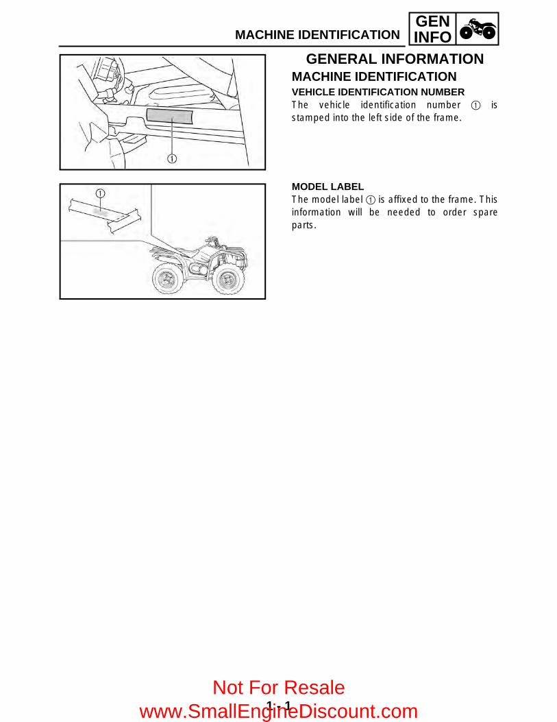
GENERAL INFORMATIONMACHINE IDENTIFICATIONVEHICLE IDENTIFICATION NUMBERThe vehicle identification number 1 isstamped into the left side of the frame.
MODEL LABELThe model label 1 is affixed to the frame. Thisinformation will be needed to order spareparts.
Not For Resale www.SmallEngineDiscount.com
1 - 2
GENINFO
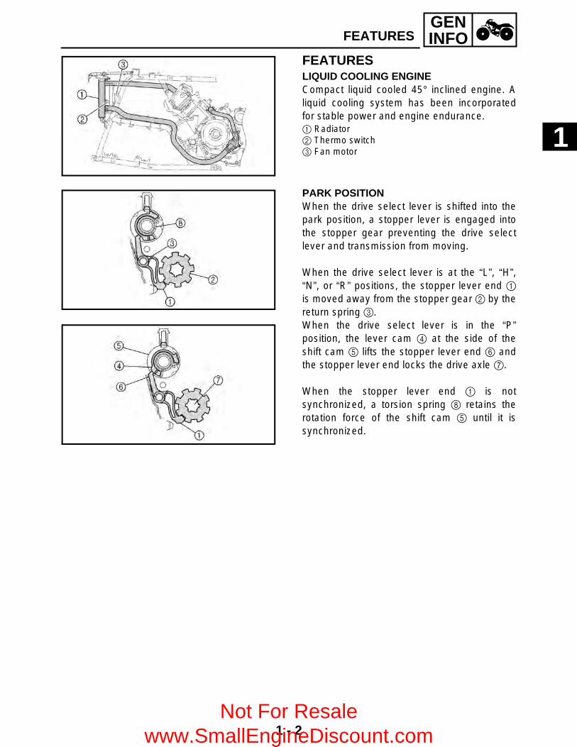
FEATURESLIQUID COOLING ENGINECompact liquid cooled 45° inclined engine. Aliquid cooling system has been incorporatedfor stable power and engine endurance.1 Radiator2 Thermo switch3 Fan motor
PARK POSITIONWhen the drive select lever is shifted into thepark position, a stopper lever is engaged intothe stopper gear preventing the drive selectlever and transmission from moving.
When the drive select lever is at the “L”, “H”,“N”, or “R” positions, the stopper lever end 1is moved away from the stopper gear 2 by thereturn spring 3.When the drive select lever is in the “P”position, the lever cam 4 at the side of theshift cam 5 lifts the stopper lever end 6 andthe stopper lever end locks the drive axle 7.
When the stopper lever end 1 is notsynchronized, a torsion spring 8 retains therotation force of the shift cam 5 until it issynchronized.
FEATURES
1
Not For Resale www.SmallEngineDiscount.com

GENINFO
1 - 3
FEATURES
FRONT DIFFERENTIAL1 Adapter2 Drive clutch3 Differential side gear (left)4 Differential pinion gear5 Ring gear6 Differential side gear (right)
7 Drive pinion gear8 Gear motor
È To front wheelÉ From the middle gear
Not For Resale www.SmallEngineDiscount.com

GENINFO
1 - 4
FEATURES
2WDPower is transmitted as follows: middle gear → front drive shaft → drive pinion gear 7 → ring gear5 → differential pinion gear 4. In the 2WD mode, the left differential side gear 3 and the driveclutch 2 are not engaged, therefore, the left side gear runs idle and does not transmit power to theleft front constant velocity joint.
Not For Resale www.SmallEngineDiscount.com

GENINFO
1 - 5
FEATURES
4WDWhen the 4WD mode is selected, the gear motor is operated, and the drive clutch 2 moves to theright and engages with the left differential side gear 3. Accordingly, power is transmitted as follows:ring gear 5 → differential pinion gear 4 → left differential side gear 3 → drive clutch 2 → adapter1 → left front constant velocity joint.Meanwhile, power from the differential pinion gear 4 is transmitted to the right front constantvelocity joint via the right differential side gear 6. The ring gear 5 and the drive clutch 2 are not engaged at this time. Therefore, the rotationaldifference that occurs between the right and left wheels, while the handlebar is being turned, isabsorbed by the difference in the rotational speeds of the ring gear 5 and the left differential sidegear 3.
Not For Resale www.SmallEngineDiscount.com

GENINFO
1 - 6
FEATURES
4WD (Diff-Lock)When the 4WD (Diff-Lock) mode is selected, the gear motor moves the drive clutch 2 further to theright, which causes the ring gear 5 and the drive clutch 2 to engage. As a result, power istransmitted directly from the ring gear 5 to the drive clutch 2, then to the left front constant velocityjoint via the adapter 1.Meanwhile, because the ring gear 5 and the drive clutch 2 are engaged, the ring gear 5, the driveclutch 2, and the right differential side gear 6 become locked coaxially. Thus, power is transmittedas follows: differential pinion gear 4 → right differential pinion gear 6 → right front constantvelocity joint.When the ATV is in the 4WD (Diff-Lock) mode, the right and left wheels rotate constantly at thesame speed, which affects the maneuverability of the ATV (e.g., making it difficult to steer).Therefore, the maximum traveling speed is limited to 35 km/h (22 mph).
Not For Resale www.SmallEngineDiscount.com

GENINFO
1 - 7
FEATURES
In addition, the 4WD (Diff-Lock) mode can be engaged only when the ATV is stopped. Even if anattempt is made to select this mode when the ATV is traveling, it will only result in a standbycondition (i.e., when the differential lock select switch and the differential gear are not matched).(1) When the ATV is travelingEven if the 4WD (Diff-Lock) mode is selected, the gear motor will stand by, instead of operating.Therefore, the ATV can be driven in the normal 4WD mode. When this occurs, the differential gearlock indicator light “ ” in the speedometer unit will flash to alert the driver that the control is onstandby. When the ATV is stopped, the control transfers to the condition described in (2).
(2) When the ATV is stoppedThe gear motor operates to connect the drive clutch to the differential case, thus resulting in thedifferential lock condition. When this occurs, the differential gear lock indicator light “ ” in thespeedometer unit changes to a constant illumination.* Until the drive clutch and the differential case mesh together (i.e., the splines are unmeshed) theengine misfires to control the engine speed. During this time, the differential gear lock indicator lightin the speedometer unit continues to flash.
DIFF.LOCK
DIFF.LOCK
Not For Resale www.SmallEngineDiscount.com
1 - 8
GENINFO
EB101000
IMPORTANT INFORMATIONPREPARATION FOR REMOVAL PROCEDURES1.Remove all dirt, mud, dust and foreign
material before removal and disassembly.2.Use proper tools and cleaning equipment.
Refer to the “SPECIAL TOOLS” section.3.When disassembling the machine, always
keep mated parts together. This includesgears, cylinder, piston and other parts thathave been “mated” through normal wear.Mated parts must always be reused orreplaced as an assembly.
4.During machine disassembly, clean all partsand place them in trays in the order ofdisassembly. This will speed up assemblyand allow for the correct installation of allparts.
5.Keep all parts away from any source of fire.
EB101010
REPLACEMENT PARTS1.Use only genuine Yamaha parts for all
replacements. Use oil and greaserecommended by Yamaha for all lubricationjobs. Other brands may be similar in functionand appearance, but inferior in quality.
EB101020
GASKETS, OIL SEALS AND O-RINGS1.Replace all gaskets, seals and O-rings when
overhauling the engine. All gasket surfaces,oil seal lips and O-rings must be cleaned.
2.Properly oil all mating parts and bearingsduring reassembly. Apply grease to the oilseal lips.
IMPORTANT INFORMATION
Not For Resale www.SmallEngineDiscount.com

1 - 9
GENINFO
EB101030
LOCK WASHERS/PLATES AND COTTER PINS1.Replace all lock washers/plates 1 and cotter
pins after removal. Bend lock tabs along thebolt or nut flats after the bolt or nut has beentightened to specification.
EB101040
BEARINGS AND OIL SEALS1.Install bearings and oil seals so that the
manufacturer’s marks or numbers are visible.When installing oil seals, apply a lightcoating of lightweight lithium base grease tothe seal lips. Oil bearings liberally wheninstalling, if appropriate.
1 Oil seal
CAUTION:Do not use compressed air to spin thebearings dry. This will damage the bearingsurfaces.
1 Bearing
EB101050
CIRCLIPS1.Check all circlips carefully before
reassembly. Always replace piston pin clipsafter one use. Replace distorted circlips.When installing a circlip 1, make sure thatthe sharp-edged corner 2 is positionedopposite the thrust 3 it receives. Seesectional view.
4 Shaft
IMPORTANT INFORMATION
Not For Resale www.SmallEngineDiscount.com
1 - 10
GENINFOCHECKING OF CONNECTIONS
EB801000
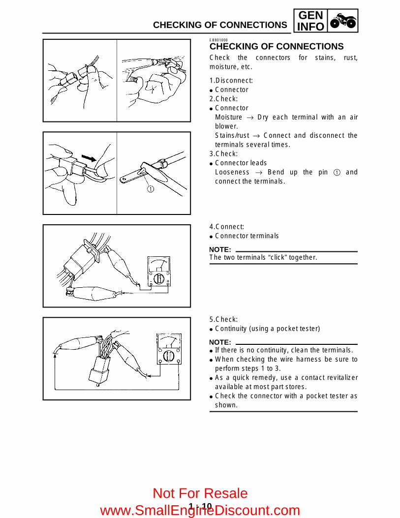
CHECKING OF CONNECTIONSCheck the connectors for stains, rust,moisture, etc.
1.Disconnect: Connector2.Check: Connector
Moisture → Dry each terminal with an airblower. Stains/rust → Connect and disconnect theterminals several times.
3.Check: Connector leads
Looseness → Bend up the pin 1 andconnect the terminals.
4.Connect: Connector terminals
NOTE:The two terminals “click” together.
5.Check: Continuity (using a pocket tester)
NOTE: If there is no continuity, clean the terminals. When checking the wire harness be sure to
perform steps 1 to 3. As a quick remedy, use a contact revitalizer
available at most part stores. Check the connector with a pocket tester as
shown.
Not For Resale www.SmallEngineDiscount.com
GENINFO
1 - 11
SPECIAL TOOLSEB102001
SPECIAL TOOLSThe following special tools are necessary for complete and accurate tune-up and assembly. Useonly the appropriate special tools; this will help prevent damage caused by the use of inappropriatetools or improvised techniques. Special tools may differ by shape and part number from country tocountry. In such a case, two types are provided.When placing an order, refer to the list provided below to avoid any mistakes.
For US and CDNP/N. YM-, YU-, YS-, YK-, ACC-
Except for US and CDNP/N. 90890-
Tool No. Tool name/How to use Illustration
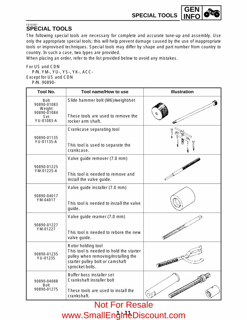
Bolt90890-01083
Weight90890-01084
SetYU-01083-A
Slide hammer bolt (M6)/weight/set
These tools are used to remove the rocker arm shaft.
90890-01135YU-01135-A
Crankcase separating tool
This tool is used to separate the crankcase.
90890-01225YM-01225-A
Valve guide remover (7.0 mm)
This tool is needed to remove and install the valve guide.
90890-04017YM-04017
Valve guide installer (7.0 mm)
This tool is needed to install the valve guide.
90890-01227YM-01227
Valve guide reamer (7.0 mm)
This tool is needed to rebore the new valve guide.
90890-01235YU-01235
Rotor holding toolThis tool is needed to hold the starter pulley when removing/installing the starter pulley bolt or camshaft sprocket bolts.
90890-04088Bolt
90890-01275
Buffer boss installer setCrankshaft installer bolt
These tools are used to install the crankshaft.
Not For Resale www.SmallEngineDiscount.com

GENINFO
1 - 12
SPECIAL TOOLS
YU-90050
Crankshaft installer set
These tools are used to install the crankshaft.
AdapterYM-33279
Spacer90890-04060YM-90070-A
Adapter (#11)Spacer (crankshaft)
These tools are used to install the crankshaft.
90890-01304YU-01304
Piston pin puller set
This tool is used to remove the piston pin.
90890-01311YU-08035
Tappet adjusting tool (3 mm)
This tool is necessary for adjusting the valve clearance.
90890-01312YM-01312-A
Fuel level gauge
This gauge is used to measure the fuel level in the float chamber.
90890-01325YU-24460-01
Radiator cap tester
This tool is used to check the cooling system.
90890-01352YU-33984
Adapter
This tool is used to check the cooling system.
90890-01348
Locknut wrench
This tool is needed when removing or installing the secondary sheave spring.
90890-04134YM-04134
Sheave spring compressor
This tool is needed when removing or installing the secondary sheave spring.
Tool No. Tool name/How to use Illustration
Not For Resale www.SmallEngineDiscount.com

GENINFO
1 - 13
SPECIAL TOOLS
90890-04135YM-04135
Sheave fixed block
This tool is needed when removing or installing the secondary sheave spring.
90890-01404YM-01404
Flywheel puller
These tools are needed to remove the rotor.
90890-01327YM-01327
Damper rod holder (30 mm)
This tool is needed to loosen and tighten the steering stem bearing retainer.
90890-01426YU-38411
Oil filter wrench
This tool is needed to loosen or tighten the oil filter cartridge.
90890-01430YM-38404
Ring nut wrench
This tool is needed to removing and installing the middle driven shaft bearing retainer.
90890-01467YM-01467
90890-01475YM-01475
Gear lash measurement tool
This tool is used to measure the gear lash.
90890-01474YM-01474
Ball joint remover/installer set
This tool is used to remove and install the ball joint.
YM-01477
Ball joint remover/installer attachment set
This tool is used to remove and install the ball joint.
90890-01701YU-01880
Sheave holder
This tool is needed to hold the primary sheave when removing or installing the sheave bolts.
Tool No. Tool name/How to use Illustration
Not For Resale www.SmallEngineDiscount.com

GENINFO
1 - 14
SPECIAL TOOLS
Compression gauge90890-03081
YU-33223Adapter
90890-04082YU-33223-3
Compression gaugeAdapter
These tools are needed to measure engine compression.
90890-03112YU-03112
Pocket tester
This instrument is needed for checking the electrical system.
90890-03113
Engine tachometer
This tool is needed for observing engine rpm.
YU-8036-A
Inductive tachometer
This tool is needed for observing engine rpm.
90890-03141YM-33277-A
Timing light
This tool is necessary for checking ignition timing.
90890-04019YM-04019
Valve spring compressor
This tool is needed to remove and install the valve assemblies.
Middle driven shaft bearing driver90890-04058YM-04058-1
Mechanical seal installer90890-04078
YM-33221
Middle driven shaft bearing driverMechanical seal installer
These tools are used to install the water pump seal.
90890-04050YM-04050
Bearing retainer wrench
This tool is needed when removing or installing the final drive shaft bearing retainer.
90890-04062YM-04062
Universal joint holder
This tool is needed when removing or installing the universal joint yoke nut.
Tool No. Tool name/How to use Illustration
Not For Resale www.SmallEngineDiscount.com
GENINFO
1 - 15
SPECIAL TOOLS
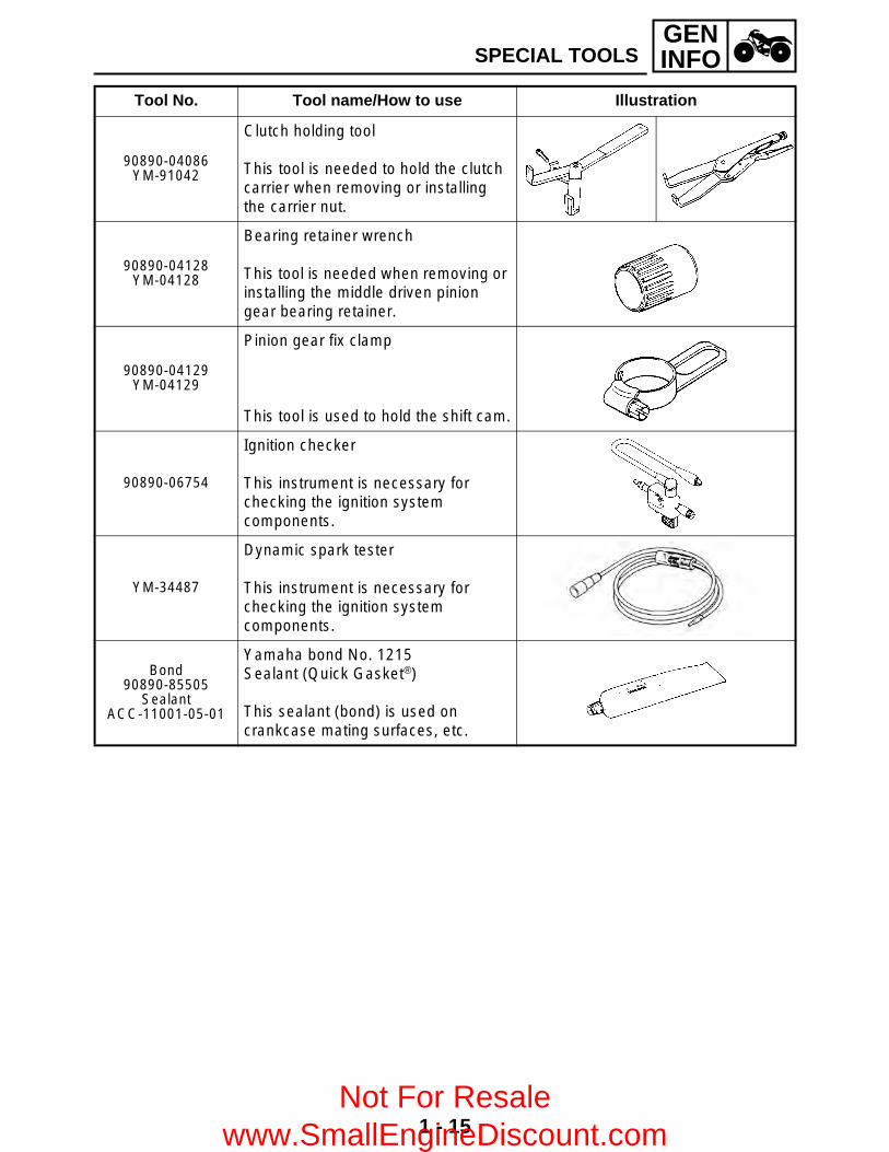
90890-04086YM-91042
Clutch holding tool
This tool is needed to hold the clutch carrier when removing or installing the carrier nut.
90890-04128YM-04128
Bearing retainer wrench
This tool is needed when removing or installing the middle driven pinion gear bearing retainer.
90890-04129YM-04129
Pinion gear fix clamp
This tool is used to hold the shift cam.
90890-06754
Ignition checker
This instrument is necessary for checking the ignition system components.
YM-34487
Dynamic spark tester
This instrument is necessary for checking the ignition system components.
Bond90890-85505
SealantACC-11001-05-01
Yamaha bond No. 1215Sealant (Quick Gasket®)
This sealant (bond) is used on crankcase mating surfaces, etc.
Tool No. Tool name/How to use Illustration
Not For Resale www.SmallEngineDiscount.com
2 - 1
SPEC
SPECIFICATIONSGENERAL SPECIFICATIONS
Item Standard
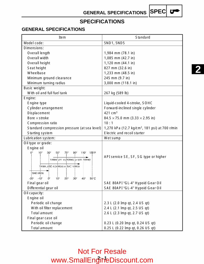
Model code: 5ND1, 5ND5 Dimensions:
Overall length 1,984 mm (78.1 in)Overall width 1,085 mm (42.7 in)Overall height 1,120 mm (44.1 in)Seat height 827 mm (32.6 in)Wheelbase 1,233 mm (48.5 in)Minimum ground clearance 245 mm (9.7 in)Minimum turning radius 3,000 mm (118.1 in)
Basic weight:With oil and full fuel tank 267 kg (589 lb)
Engine:Engine type Liquid-cooled 4-stroke, SOHCCylinder arrangement Forward-inclined single cylinderDisplacement 421 cm3 Bore × stroke 84.5 × 75.0 mm (3.33 × 2.95 in)Compression ratio 10 : 1Standard compression pressure (at sea level) 1,270 kPa (12.7 kg/cm2, 181 psi) at 700 r/minStarting system Electric and recoil starter
Lubrication system: Wet sumpOil type or grade:
Engine oil
API service SE, SF, SG type or higher
Final gear oil SAE 80API “GL-4” Hypoid Gear OilDifferential gear oil SAE 80API “GL-4” Hypoid Gear Oil
Oil capacity:Engine oil
Periodic oil change 2.3 L (2.0 Imp qt, 2.4 US qt)With oil filter replacement 2.4 L (2.1 lmp qt, 2.5 US qt)Total amount 2.6 L (2.3 lmp qt, 2.7 US qt)
Final gear case oilPeriodic oil change 0.23 L (0.20 Imp qt, 0.24 US qt)Total amount 0.25 L (0.22 Imp qt, 0.26 US qt)
GENERAL SPECIFICATIONS
2
Not For Resale www.SmallEngineDiscount.com
2 - 2
SPEC
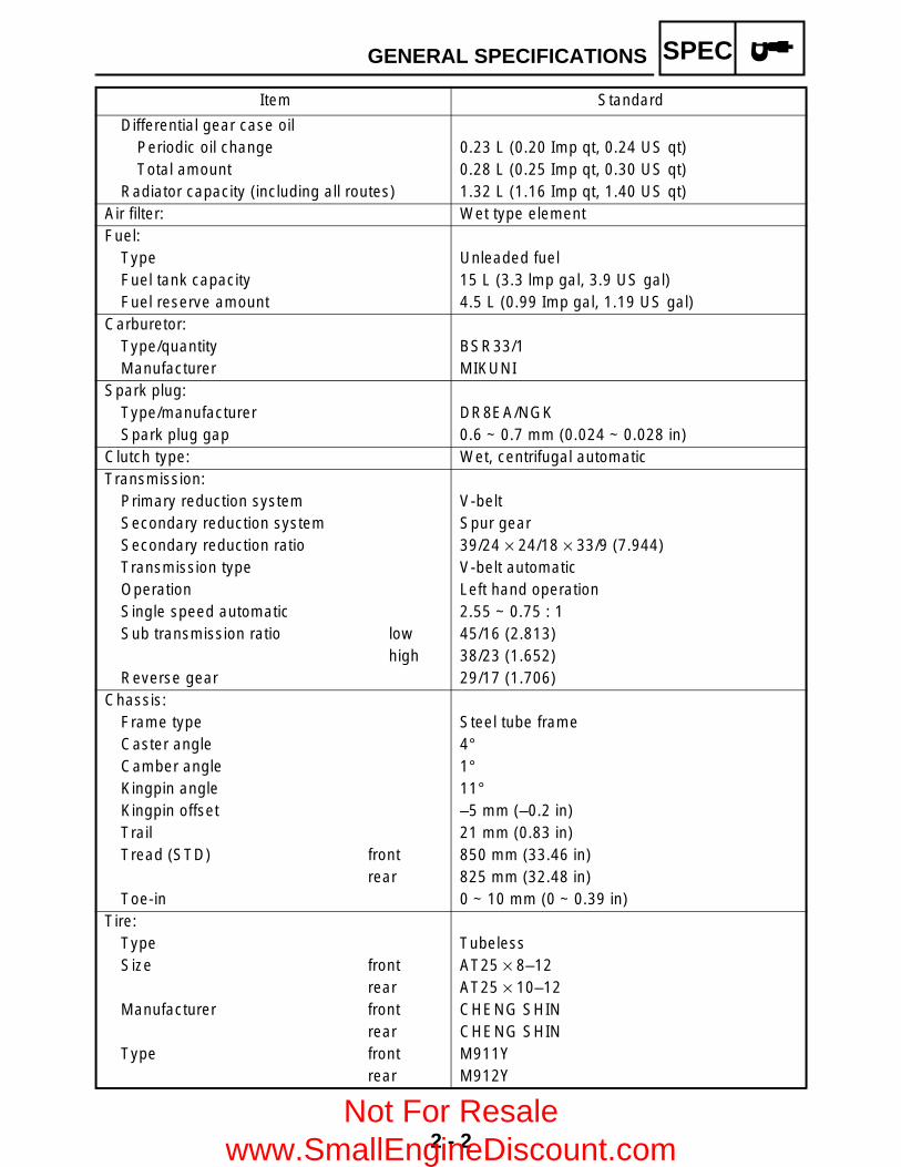
Differential gear case oilPeriodic oil change 0.23 L (0.20 Imp qt, 0.24 US qt)Total amount 0.28 L (0.25 Imp qt, 0.30 US qt)
Radiator capacity (including all routes) 1.32 L (1.16 Imp qt, 1.40 US qt)Air filter: Wet type elementFuel:
Type Unleaded fuelFuel tank capacity 15 L (3.3 lmp gal, 3.9 US gal)Fuel reserve amount 4.5 L (0.99 Imp gal, 1.19 US gal)
Carburetor:Type/quantity BSR33/1Manufacturer MIKUNI
Spark plug:Type/manufacturer DR8EA/NGKSpark plug gap 0.6 ~ 0.7 mm (0.024 ~ 0.028 in)
Clutch type: Wet, centrifugal automaticTransmission:
Primary reduction system V-beltSecondary reduction system Spur gearSecondary reduction ratio 39/24 × 24/18 × 33/9 (7.944)Transmission type V-belt automaticOperation Left hand operationSingle speed automatic 2.55 ~ 0.75 : 1Sub transmission ratio low 45/16 (2.813)
high 38/23 (1.652)Reverse gear 29/17 (1.706)
Chassis:Frame type Steel tube frameCaster angle 4°Camber angle 1°Kingpin angle 11°Kingpin offset –5 mm (–0.2 in)Trail 21 mm (0.83 in)Tread (STD) front 850 mm (33.46 in)
rear 825 mm (32.48 in)Toe-in 0 ~ 10 mm (0 ~ 0.39 in)
Tire:Type TubelessSize front AT25 × 8–12
rear AT25 × 10–12Manufacturer front CHENG SHIN
rear CHENG SHINType front M911Y
rear M912Y
Item Standard
GENERAL SPECIFICATIONS
Not For Resale www.SmallEngineDiscount.com
2 - 3
SPEC
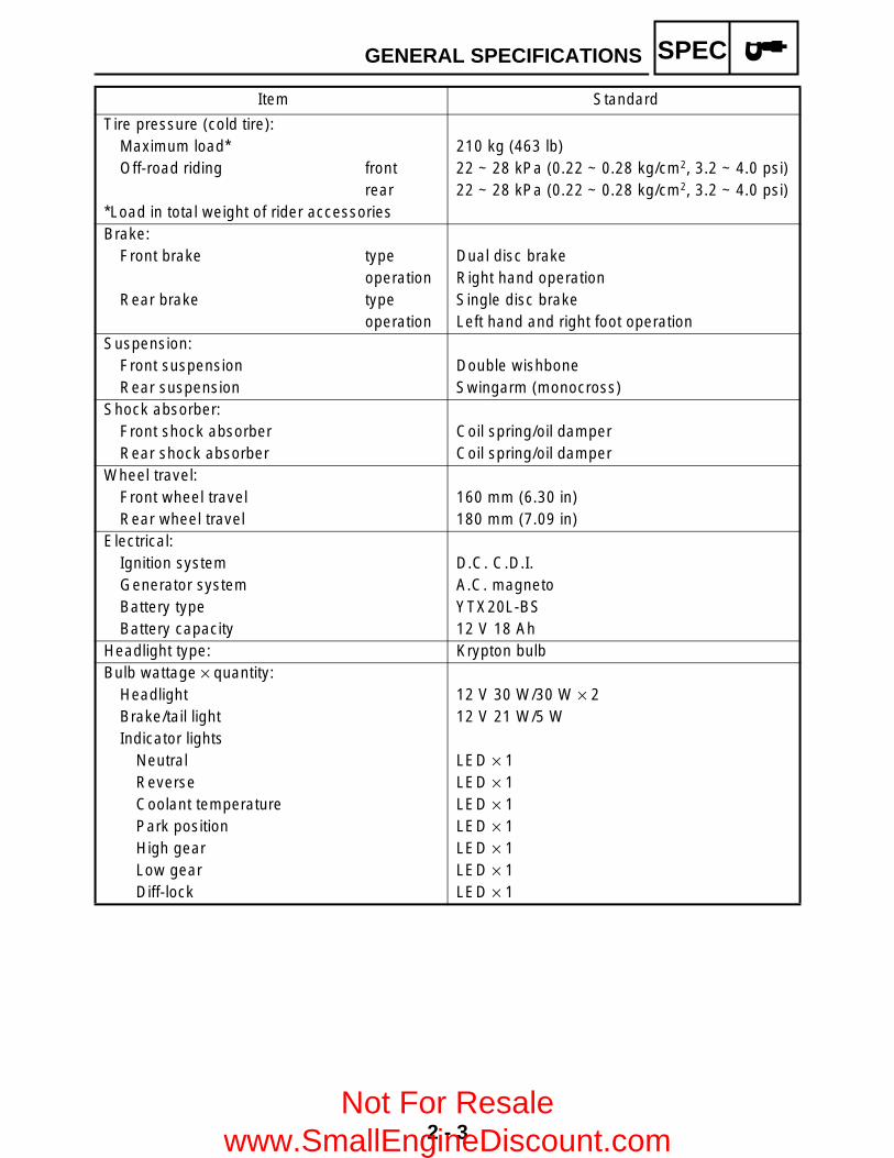
Tire pressure (cold tire):Maximum load* 210 kg (463 lb)Off-road riding front 22 ~ 28 kPa (0.22 ~ 0.28 kg/cm2, 3.2 ~ 4.0 psi)
rear 22 ~ 28 kPa (0.22 ~ 0.28 kg/cm2, 3.2 ~ 4.0 psi)*Load in total weight of rider accessoriesBrake:
Front brake type Dual disc brakeoperation Right hand operation
Rear brake type Single disc brakeoperation Left hand and right foot operation
Suspension:Front suspension Double wishboneRear suspension Swingarm (monocross)
Shock absorber:Front shock absorber Coil spring/oil damperRear shock absorber Coil spring/oil damper
Wheel travel:Front wheel travel 160 mm (6.30 in)Rear wheel travel 180 mm (7.09 in)
Electrical:Ignition system D.C. C.D.I.Generator system A.C. magnetoBattery type YTX20L-BSBattery capacity 12 V 18 Ah
Headlight type: Krypton bulbBulb wattage × quantity:
Headlight 12 V 30 W/30 W × 2Brake/tail light 12 V 21 W/5 WIndicator lights
Neutral LED × 1Reverse LED × 1Coolant temperature LED × 1Park position LED × 1High gear LED × 1Low gear LED × 1Diff-lock LED × 1
Item Standard
GENERAL SPECIFICATIONS
Not For Resale www.SmallEngineDiscount.com

2 - 4
SPEC
MAINTENANCE SPECIFICATIONSENGINE
Item Standard Limit
Cylinder head:Warp limit ---- 0.03 mm
(0.0012 in)
Cylinder:Bore size 84.500 ~ 84.510 mm
(3.3268 ~ 3.3272 in)84.600 mm (3.3307 in)
Taper limit ---- 0.05 mm (0.0016 in)
Out of round limit ---- 0.01 mm (0.0004 in)
Camshaft:Drive method Chain drive (Left) ----Cam dimensions
Intake “A” 40.62 ~ 40.72 mm (1.5992 ~ 1.6031 in)
40.52 mm (1.5953 in)
“B” 32.18 ~ 32.28 mm (1.2669 ~ 1.2709 in)
32.08 mm (1.2630 in)
Exhaust “A” 40.62 ~ 40.72 mm (1.5992 ~ 1.6031 in)
40.52 mm (1.5953 in)
“B” 32.18 ~ 32.28 mm(1.2669 ~ 1.2709 in)
32.08 mm (1.2630 in)
Camshaft runout limit ---- 0.03 mm (0.0012 in)
A
B
MAINTENANCE SPECIFICATIONS
Not For Resale www.SmallEngineDiscount.com

2 - 5
SPEC
Cam chain:Cam chain type/No. of links DID SCR-0409 SDH/116 ----Cam chain adjustment method Automatic ----
Rocker arm/rocker arm shaft:Bearing inside diameter 12.000 ~ 12.018 mm
(0.4724 ~ 0.4731 in)12.078 mm (0.4755 in)
Shaft outside diameter 11.981 ~ 11.991 mm (0.4717 ~ 0.4721 in)
11.951 mm (0.4705 in)
Arm-to-shaft clearance 0.009 ~ 0.037 mm (0.0004 ~ 0.0015 in)
0.080 mm (0.0031 in)
Valve, valve seat, valve guide:Valve clearance (cold) IN 0.06 ~ 0.10 mm
(0.0024 ~ 0.0039 in)----
EX 0.16 ~ 0.20 mm(0.0063 ~ 0.0079 in)
----
Valve dimensions
“A” head diameter IN 39.9 ~ 40.1 mm(1.5708 ~ 1.5787 in)
----
EX 33.9 ~ 34.1 mm(1.3346 ~ 1.3425 in)
----
“B” face width IN 2.26 mm (0.0890 in) ----EX 2.26 mm (0.0890 in) ----
“C” seat width IN 1.2 ~ 1.4 mm (0.0472 ~ 0.0551 in)
1.6 mm (0.0630 in)
EX 1.2 ~ 1.4 mm(0.0472 ~ 0.0551 in)
1.6 mm (0.0630 in)
“D” margin thickness IN 1.0 ~ 1.4 mm(0.0394 ~ 0.0551 in)
----
EX 0.8 ~ 1.2 mm (0.0315 ~ 0.0472 in)
----
Stem outside diameter IN 6.975 ~ 6.990 mm(0.2746 ~ 0.2752 in)
6.950 mm (0.2736 in)
EX 6.955 ~ 6.970 mm(0.2738 ~ 0.2744 in)
6.915 mm (0.2722 in)
Guide inside diameter IN 7.000 ~ 7.012 mm (0.2756 ~ 0.2761 in)
7.030 mm (0.2768 in)
EX 7.000 ~ 7.012 mm (0.2756 ~ 0.2761 in)
7.030 mm (0.2768 in)
Stem-to-guide clearance IN 0.010 ~ 0.037 mm (0.0004 ~ 0.0015 in)
0.080 mm (0.0031 in)
EX 0.030 ~ 0.057 mm (0.0012 ~ 0.0022 in)
0.100 mm (0.0039 in)
Item Standard Limit
Head Diameter
B
Face Width
C
Seat Width
D
Margin Thickness
A
MAINTENANCE SPECIFICATIONS
Not For Resale www.SmallEngineDiscount.com

2 - 6
SPEC
Stem runout limit ---- 0.01 mm (0.0004 in)
Valve seat width IN 1.2 ~ 1.4 mm (0.0472 ~ 0.0551 in)
----
EX 1.2 ~ 1.4 mm (0.0472 ~ 0.0551 in)
----
Valve spring:Inner spring
Free length IN 39.9 mm (1.57 in) 37.9 mm (1.49 in)
EX 39.9 mm (1.57 in) 37.9 mm (1.49 in)
Set length (valve closed) IN 33.6 mm (1.32 in) ----EX 33.6 mm (1.32 in) ----
Compressed pressure(installed) IN 104.9 ~ 120.6 N (10.70 ~
12.30 kg, 23.58 ~ 27.11 lb)----
EX 104.9 ~ 120.6 N (10.70 ~ 12.30 kg, 23.58 ~ 27.11 lb)
----
Tilt limit IN 2.5°/1.6 mm (2.5°/0.06 in)
EX 2.5°/1.6 mm (2.5°/0.06 in)
Direction of winding(top view) IN Counterclockwise ----
EX Counterclockwise ----Outer spring
Free length IN 43.27 mm (1.70 in) 41.27 mm (1.62 in)
EX 43.27 mm (1.70 in) 41.27 mm (1.62 in)
Set length (valve closed) IN 36.6 mm (1.44 in) ----EX 36.6 mm (1.44 in) ----
Compressed pressure(installed) IN 235.4 ~ 251.1 N (24.00 ~
25.60 kg, 52.91 ~ 56.45 lb)----
EX 235.4 ~ 251.1 N (24.00 ~ 25.60 kg, 52.91 ~ 56.45 lb)
----
Item Standard Limit
*
MAINTENANCE SPECIFICATIONS
Not For Resale www.SmallEngineDiscount.com
2 - 7
SPEC
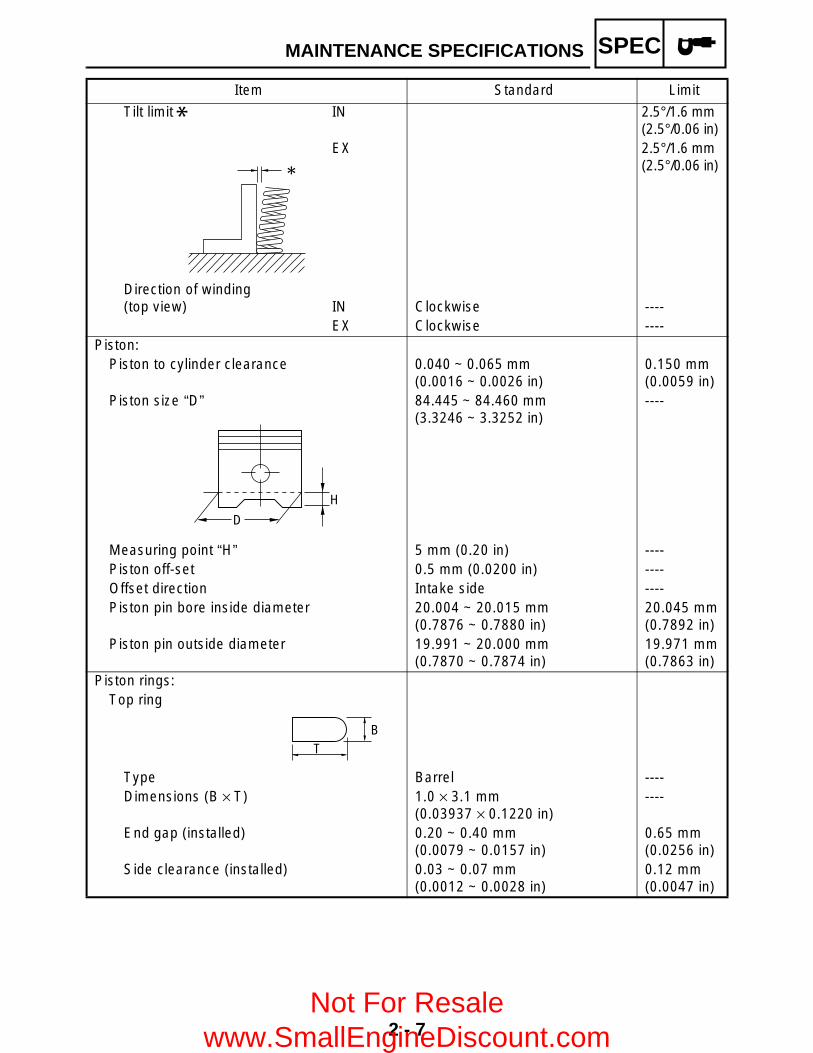
Tilt limit IN 2.5°/1.6 mm (2.5°/0.06 in)
EX 2.5°/1.6 mm (2.5°/0.06 in)
Direction of winding(top view) IN Clockwise ----
EX Clockwise ----Piston:
Piston to cylinder clearance 0.040 ~ 0.065 mm (0.0016 ~ 0.0026 in)
0.150 mm (0.0059 in)
Piston size “D” 84.445 ~ 84.460 mm (3.3246 ~ 3.3252 in)
----
Measuring point “H” 5 mm (0.20 in) ----Piston off-set 0.5 mm (0.0200 in) ----Offset direction Intake side ----Piston pin bore inside diameter 20.004 ~ 20.015 mm
(0.7876 ~ 0.7880 in)20.045 mm (0.7892 in)
Piston pin outside diameter 19.991 ~ 20.000 mm(0.7870 ~ 0.7874 in)
19.971 mm (0.7863 in)
Piston rings:Top ring
Type Barrel ----Dimensions (B × T) 1.0 × 3.1 mm
(0.03937 × 0.1220 in)----
End gap (installed) 0.20 ~ 0.40 mm(0.0079 ~ 0.0157 in)
0.65 mm (0.0256 in)
Side clearance (installed) 0.03 ~ 0.07 mm (0.0012 ~ 0.0028 in)
0.12 mm (0.0047 in)
Item Standard Limit
*
H
D
TB
MAINTENANCE SPECIFICATIONS
Not For Resale www.SmallEngineDiscount.com
2 - 8
SPEC
2nd ring
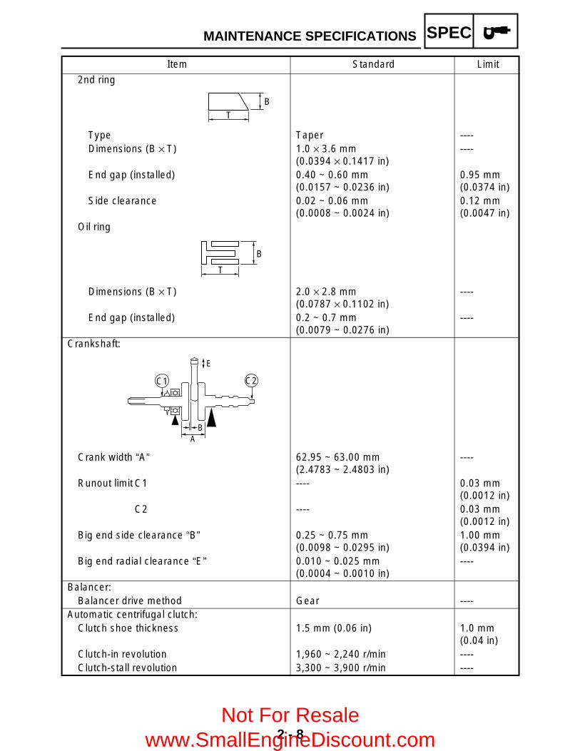
Type Taper ----Dimensions (B × T) 1.0 × 3.6 mm
(0.0394 × 0.1417 in)----
End gap (installed) 0.40 ~ 0.60 mm(0.0157 ~ 0.0236 in)
0.95 mm (0.0374 in)
Side clearance 0.02 ~ 0.06 mm (0.0008 ~ 0.0024 in)
0.12 mm (0.0047 in)
Oil ring
Dimensions (B × T) 2.0 × 2.8 mm(0.0787 × 0.1102 in)
----
End gap (installed) 0.2 ~ 0.7 mm(0.0079 ~ 0.0276 in)
----
Crankshaft:
Crank width “A” 62.95 ~ 63.00 mm (2.4783 ~ 2.4803 in)
----
Runout limit C1 ---- 0.03 mm (0.0012 in)
C2 ---- 0.03 mm (0.0012 in)
Big end side clearance “B” 0.25 ~ 0.75 mm (0.0098 ~ 0.0295 in)
1.00 mm (0.0394 in)
Big end radial clearance “E” 0.010 ~ 0.025 mm (0.0004 ~ 0.0010 in)
----
Balancer:Balancer drive method Gear ----
Automatic centrifugal clutch:Clutch shoe thickness 1.5 mm (0.06 in) 1.0 mm
(0.04 in)Clutch-in revolution 1,960 ~ 2,240 r/min ----Clutch-stall revolution 3,300 ~ 3,900 r/min ----
Item Standard Limit
BT
B
T
E
AB
C1 C2
MAINTENANCE SPECIFICATIONS
Not For Resale www.SmallEngineDiscount.com
2 - 9
SPEC
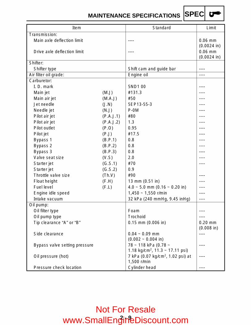
Transmission:Main axle deflection limit ---- 0.06 mm
(0.0024 in)Drive axle deflection limit ---- 0.06 mm
(0.0024 in)Shifter:
Shifter type Shift cam and guide bar ----Air filter oil grade: Engine oil ----Carburetor:
I. D. mark 5ND1 00 ----Main jet (M.J) #131.3 ----Main air jet (M.A.J) #50 ----Jet needle (J.N) 5EP13-55-3 ----Needle jet (N.J) P-0M ----Pilot air jet (P.A.J.1) #80 ----Pilot air jet (P.A.J.2) 1.3 ----Pilot outlet (P.O) 0.95 ----Pilot jet (P.J) #17.5 ----Bypass 1 (B.P.1) 0.8 ----Bypass 2 (B.P.2) 0.8 ----Bypass 3 (B.P.3) 0.8 ----Valve seat size (V.S) 2.0 ----Starter jet (G.S.1) #70 ----Starter jet (G.S.2) 0.9Throttle valve size (Th.V) #90 ----Float height (F.H) 13 mm (0.51 in) ----Fuel level (F.L) 4.0 ~ 5.0 mm (0.16 ~ 0.20 in) ----Engine idle speed 1,450 ~ 1,550 r/min ----Intake vacuum 32 kPa (240 mmHg, 9.45 inHg) ----
Oil pump:Oil filter type Foam ----Oil pump type Trochoid ----Tip clearance “A” or “B” 0.15 mm (0.006 in) 0.20 mm
(0.008 in)Side clearance 0.04 ~ 0.09 mm
(0.002 ~ 0.004 in)----
Bypass valve setting pressure 78 ~ 118 kPa (0.78 ~ 1.18 kg/cm2, 11.3 ~ 17.11 psi)
----
Oil pressure (hot) 7 kPa (0.07 kg/cm2, 1.02 psi) at 1,500 r/min
----
Pressure check location Cylinder head ----
Item Standard Limit
MAINTENANCE SPECIFICATIONS
Not For Resale www.SmallEngineDiscount.com

2 - 10
SPEC
Cooling system:Radiator core
Width 300 mm (11.8 in) ----Height 208 mm (8.19 in) ----Thickness 26 mm (1.02 in) ----
Radiator cap opening pressure 93.7 ~ 122.6 kPa (0.937 ~ 1.226 kg/cm2, 13.32 ~ 17.43 psi)
----
Radiator capacity 0.70 L (0.62 Imp qt, 0.74 US qt) ----Coolant reservoir
Capacity 0.39 L (0.34 Imp qt, 0.41 US qt) ----From low to full level 0.15 L (0.13 Imp qt, 0.16 US qt) ----
Water pump:Type Single suction centrifugal pump ----Reduction ratio 38/32 (1.188)
Thermostat:Valve opening temperature 63.5 ~ 66.5 °C (146.3 ~ 151.7 °F) ----Valve full open temperature 80 °C (176 °F) ----Valve lift-full open 3 mm (0.12 in) ----
Shaft drive:Middle gear backlash 0.1 ~ 0.3 mm (0.004 ~ 0.012 in) ----Final gear backlash 0.1 ~ 0.2 mm (0.004 ~ 0.008 in) ----Differential gear backlash 0.05 ~ 0.25 mm
(0.0020 ~ 0.0098 in)----
Lubrication chart:
Item Standard Limit
Oil Strainer
Timing Chain Area
Transmission
Rocker Arm
Oil Pump
Piston PinPiston
Crank Pin
Cam Shaft
Oil Filter
Bypass Valve
Clutch
Valve
Pressure feed
Splashed scavenge
MAINTENANCE SPECIFICATIONS
Not For Resale www.SmallEngineDiscount.com

2 - 11
SPEC
Cylinder head tightening sequence:
Item Standard Limit
MAINTENANCE SPECIFICATIONS
Not For Resale www.SmallEngineDiscount.com

2 - 12
SPEC
Tightening torques
Part to be tightenedPart
nameThread
sizeQ’ty
Tightening torqueRemarks
Nm m·kg ft·lb
Cylinder head oil passage Union bolt M6 1 7 0.7 5.1Cylinder head (exhaust pipe) Stud bolt M8 2 15 1.5 11Cylinder head Bolt M10 4 40 4.0 29
Bolt M6 2 10 1.0 7.2Camshaft sprocket cover baffle plate
Bolt M6 2 10 1.0 7.2 LT
Camshaft bearing retainer Bolt M6 2 8 0.8 5.8Spark plug — M12 1 18 1.8 13Coolant drain bolt (cylinder) Bolt M6 1 10 1.0 7.2Starter clutch Bolt M10 1 50 5.0 36Camshaft sprocket Bolt M10 1 60 6.0 43Timing chain tensioner cap Bolt M11 1 23 2.3 17Timing chain tensioner Bolt M6 2 11 1.1 8.0Timing chain guide (intake) Bolt M6 2 10 1.0 7.2 LT
Valve adjusting screw Nut M7 2 20 2.0 14Radiator Bolt M6 2 7 0.7 5.1Oil pump assembly Screw M6 3 8 0.8 5.8Oil pump Screw M6 1 7 0.7 5.1Oil strainer cover Plug M35 1 32 3.2 23Oil drain bolt Bolt M14 1 23 2.3 17Oil pump drive gear Nut M14 1 50 5.0 36Oil delivery pipe Union bolt M8 2 18 1.8 13Oil filter bolt Union bolt M20 1 63 6.3 45 E
Oil filter cartridge — M20 1 17 1.7 12Intake manifold Bolt M8 2 20 2.0 14Muffler and exhaust pipe Bolt M8 2 15 1.5 11Exhaust pipe Nut M8 2 20 2.0 14Muffler Bolt M10 2 25 2.5 18Exhaust pipe stay Bolt M6 2 14 1.4 10Crankcase cover Screw M6 4 8 0.8 5.8 LT
Oil seal retainer Screw M5 3 7 0.7 5.1Drive belt case cover Bolt M6 12 10 1.0 7.2Crankcase oil passage plug Plug M18 1 55 5.5 40Bearing retainer (right crankcase) Screw M6 1 11 1.1 8.0 LT
Plug (right crankcase) Bolt M8 1 15 1.5 11Bearing retainer (left crankcase) Bolt M6 2 10 1.0 7.2 LT
Crankcase cover (left) Bolt M6 12 10 1.0 7.2Recoil starter Bolt M6 4 10 1.0 7.2 LT
Starter one-way clutch Bolt M8 6 30 3.0 22 LT
Clutch carrier assembly Nut M22 1 140 14 100 StakeMiddle drive shaft bearing retainer Torx
screwM8 4 25 2.5 18 LT
MAINTENANCE SPECIFICATIONS
Not For Resale www.SmallEngineDiscount.com
2 - 13
SPEC
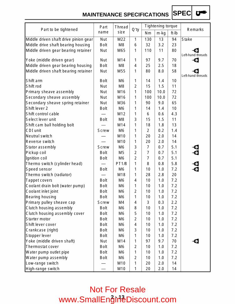
Middle driven shaft drive pinion gear Nut M22 1 130 13 94 StakeMiddle drive shaft bearing housing Bolt M8 6 32 3.2 23Middle driven gear bearing retainer Nut M65 1 110 11 80 LT
Left-hand threads
Yoke (middle driven gear) Nut M14 1 97 9.7 70 LT
Middle driven gear bearing housing Bolt M8 4 25 2.5 18Middle driven shaft bearing retainer Nut M55 1 80 8.0 58 LT
Left-hand threads
Shift arm Bolt M6 1 14 1.4 10Shift rod Nut M8 2 15 1.5 11Primary sheave assembly Nut M16 1 100 10.0 72Secondary sheave assembly Nut M16 1 100 10.0 72Secondary sheave spring retainer Nut M36 1 90 9.0 65Shift lever 2 Bolt M6 1 14 1.4 10Shift control cable — M12 1 6 0.6 4.3Select lever unit Bolt M8 3 15 1.5 11Shift cam ball holding bolt — M14 1 18 1.8 13CDI unit Screw M6 1 2 0.2 1.4Neutral switch — M10 1 20 2.0 14Reverse switch — M10 1 20 2.0 14Stator assembly Screw M6 3 7 0.7 5.1 LT
Pickup coil Bolt M5 2 7 0.7 5.1 LT
Ignition coil Bolt M6 2 7 0.7 5.1Thermo switch (cylinder head) — PT1/8 1 8 0.8 5.8 LT
Speed sensor Bolt M6 1 10 1.0 7.2 LT
Thermo switch (radiator) — M18 1 28 2.8 20Tappet covers Bolt M6 4 10 1.0 7.2Coolant drain bolt (water pump) Bolt M6 1 10 1.0 7.2Coolant inlet joint Bolt M6 2 10 1.0 7.2Bearing housing Bolt M6 1 10 1.0 7.2Primary pulley sheave cap Screw M4 4 3 0.3 2.2Clutch housing assembly Bolt M6 8 10 1.0 7.2Clutch housing assembly cover Bolt M6 5 10 1.0 7.2Starter motor Bolt M6 2 10 1.0 7.2Shift lever cover Bolt M6 4 10 1.0 7.2Crankcase (right) Bolt M6 3 10 1.0 7.2Stopper lever Bolt M6 1 10 1.0 7.2Yoke (middle driven shaft) Nut M14 1 97 9.7 70 LT
Thermostat cover Bolt M6 2 10 1.0 7.2Water pump outlet pipe Bolt M6 1 10 1.0 7.2Water pump assembly Bolt M6 2 10 1.0 7.2Low-range switch — M10 1 20 2.0 14High-range switch — M10 1 20 2.0 14
Part to be tightenedPart
nameThread
sizeQ’ty
Tightening torqueRemarks
Nm m·kg ft·lb
MAINTENANCE SPECIFICATIONS
Not For Resale www.SmallEngineDiscount.com

2 - 14
SPEC
CHASSIS
Item Standard Limit
Steering system:Steering bearing type Ball and race bearing ----
Front suspension:Shock absorber travel 99 mm (3.90 in) ----Fork spring free length 265 mm (10.43 in) ----Spring fitting length 215.8 mm (8.50 in) ----Spring rate (K1) 15 N/mm (1.53 kg/mm, 85.68 lb/in) ----Stroke (K1) 0 ~ 99 mm (0 ~ 3.90 in) ----Optional spring No ----
Rear suspension:Shock absorber travel 126 mm (4.96 in) ----Spring free length 317 mm (12.48 in) ----Spring fitting length 283 mm (11.14 in) ----Spring rate (K1) 30.4 N/mm
(3.10 kg/mm, 173.60 lb/in)----
Stroke (K1) 0 ~ 126 mm (0 ~ 4.96 in) ----Optional spring No ----
Swingarm:Free play limit end ---- 1 mm
(0.04 in)side ---- 1 mm
(0.04 in)Front wheel:
Type Panel wheel ----Rim size 12 × 6.0 AT ----Rim material Steel ----Rim runout limit radial ---- 2 mm
(0.08 in)lateral ---- 2 mm
(0.08 in)Rear wheel:
Type Panel wheel ----Rim size 12 × 7.5 AT ----Rim material Steel ----Rim runout limit radial ---- 2 mm
(0.08 in)lateral ---- 2 mm
(0.08 in)
MAINTENANCE SPECIFICATIONS
Not For Resale www.SmallEngineDiscount.com
2 - 15
SPEC
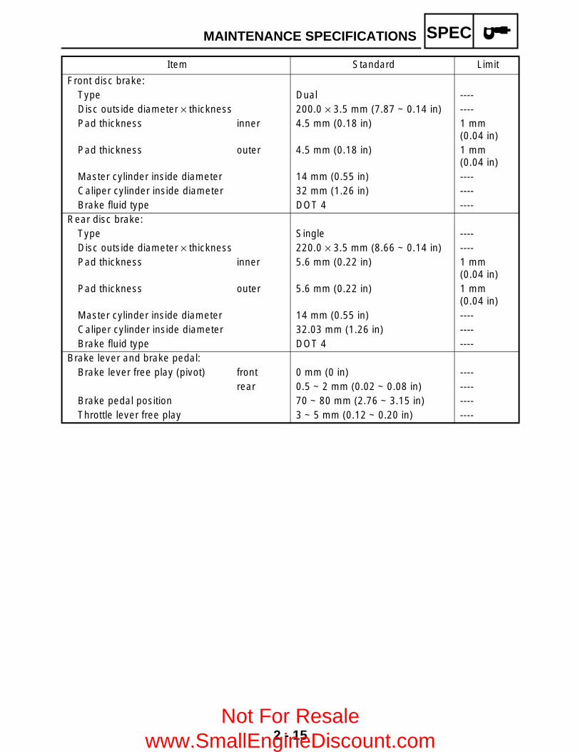
Front disc brake:Type Dual ----Disc outside diameter × thickness 200.0 × 3.5 mm (7.87 ~ 0.14 in) ----Pad thickness inner 4.5 mm (0.18 in) 1 mm
(0.04 in)Pad thickness outer 4.5 mm (0.18 in) 1 mm
(0.04 in)Master cylinder inside diameter 14 mm (0.55 in) ----Caliper cylinder inside diameter 32 mm (1.26 in) ----Brake fluid type DOT 4 ----
Rear disc brake:Type Single ----Disc outside diameter × thickness 220.0 × 3.5 mm (8.66 ~ 0.14 in) ----Pad thickness inner 5.6 mm (0.22 in) 1 mm
(0.04 in)Pad thickness outer 5.6 mm (0.22 in) 1 mm
(0.04 in)Master cylinder inside diameter 14 mm (0.55 in) ----Caliper cylinder inside diameter 32.03 mm (1.26 in) ----Brake fluid type DOT 4 ----
Brake lever and brake pedal:Brake lever free play (pivot) front 0 mm (0 in) ----
rear 0.5 ~ 2 mm (0.02 ~ 0.08 in) ----Brake pedal position 70 ~ 80 mm (2.76 ~ 3.15 in) ----Throttle lever free play 3 ~ 5 mm (0.12 ~ 0.20 in) ----
Item Standard Limit
MAINTENANCE SPECIFICATIONS
Not For Resale www.SmallEngineDiscount.com
2 - 16
SPEC
Tightening torques
Part to be tightened Thread sizeTightening torque
RemarksNm m·kg ft·lb
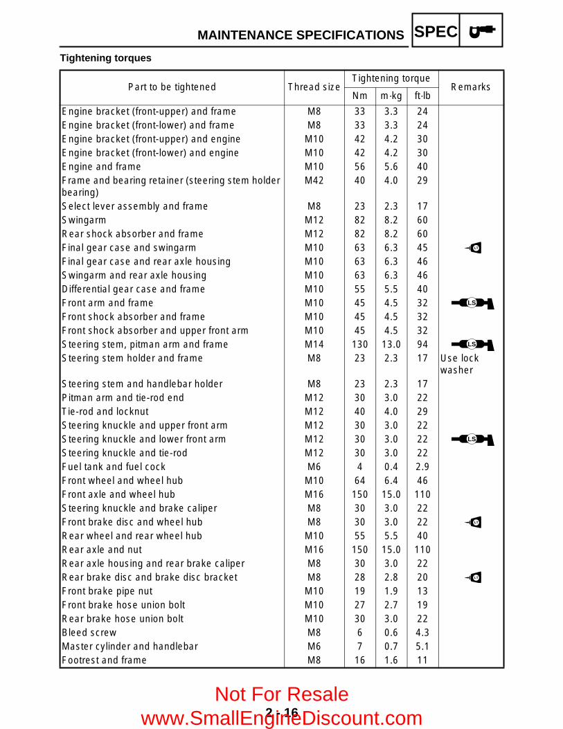
Engine bracket (front-upper) and frame M8 33 3.3 24Engine bracket (front-lower) and frame M8 33 3.3 24Engine bracket (front-upper) and engine M10 42 4.2 30Engine bracket (front-lower) and engine M10 42 4.2 30Engine and frame M10 56 5.6 40Frame and bearing retainer (steering stem holder bearing)
M42 40 4.0 29
Select lever assembly and frame M8 23 2.3 17Swingarm M12 82 8.2 60Rear shock absorber and frame M12 82 8.2 60Final gear case and swingarm M10 63 6.3 45 LT
Final gear case and rear axle housing M10 63 6.3 46Swingarm and rear axle housing M10 63 6.3 46Differential gear case and frame M10 55 5.5 40Front arm and frame M10 45 4.5 32 LS
Front shock absorber and frame M10 45 4.5 32Front shock absorber and upper front arm M10 45 4.5 32Steering stem, pitman arm and frame M14 130 13.0 94 LS
Steering stem holder and frame M8 23 2.3 17 Use lock washer
Steering stem and handlebar holder M8 23 2.3 17Pitman arm and tie-rod end M12 30 3.0 22Tie-rod and locknut M12 40 4.0 29Steering knuckle and upper front arm M12 30 3.0 22Steering knuckle and lower front arm M12 30 3.0 22 LS
Steering knuckle and tie-rod M12 30 3.0 22Fuel tank and fuel cock M6 4 0.4 2.9Front wheel and wheel hub M10 64 6.4 46Front axle and wheel hub M16 150 15.0 110Steering knuckle and brake caliper M8 30 3.0 22Front brake disc and wheel hub M8 30 3.0 22 LT
Rear wheel and rear wheel hub M10 55 5.5 40Rear axle and nut M16 150 15.0 110Rear axle housing and rear brake caliper M8 30 3.0 22Rear brake disc and brake disc bracket M8 28 2.8 20 LT
Front brake pipe nut M10 19 1.9 13Front brake hose union bolt M10 27 2.7 19Rear brake hose union bolt M10 30 3.0 22Bleed screw M8 6 0.6 4.3Master cylinder and handlebar M6 7 0.7 5.1Footrest and frame M8 16 1.6 11
MAINTENANCE SPECIFICATIONS
Not For Resale www.SmallEngineDiscount.com

2 - 17
SPEC
Front bumper and frame M8 33 3.3 24Front carrier and frame M8 33 3.3 24Front carrier and front bumper M8 33 3.3 24Rear carrier and frame M8 33 3.3 24Differential gear case filler bolt M14 23 2.3 16Differential gear case drain bolt M10 10 1.0 7Differential gear case and bearing housing M8 25 2.5 18Gear motor M8 13 1.3 9.4Final gear case oil filler bolt M14 23 2.3 16Final gear case oil drain bolt M14 23 2.3 16Bearing retainer (drive pinion gear) M65 100 10.0 72Final gear case and bearing housing M10 40 4.0 29Final gear case and bearing housing M8 23 2.3 17Battery holding bracket M6 7 0.7 5.1Footrest board and footrest bracket M6 7 0.7 5.1Yoke (drive pinion gear) M12 62 6.2 45Trailer hitch bracket M10 32 3.2 23Front brake pad holding bolt M10 18 1.8 13Rear brake pad holding bolt M10 18 1.8 13Rear brake master cylinder bracket M8 23 2.3 17Brake outer cable bracket M8 23 2.3 17Brake master cylinder cover M6 7 0.7 5.1Front brake caliper retaining bolt M8 30 3.0 22Air duct (front) M6 7 0.7 5.1
Part to be tightened Thread sizeTightening torque
RemarksNm m·kg ft·lb
MAINTENANCE SPECIFICATIONS
Not For Resale www.SmallEngineDiscount.com

2 - 18
SPEC
ELECTRICAL
Item Standard Limit
Voltage: 12 V ----Ignition system:
Ignition timing (B.T.D.C.) 10°/ 1,500 r/min ----C.D.I.:
Magneto model/manufacturer F4T46471/MITSUBISHI ----Pickup coil resistance/color 459 ~ 561 Ω at 20 °C (68 °F)/
White/Red – White/Green----
Rotor rotation direction sensing coil resistance/color
0.085 ~ 0.105 Ω at 20 °C (68 °F)/Red – White/Blue
----
C.D.I. unit model/manufacturer F8T38678/MITSUBISHI ----Ignition coil:
Model/manufacturer 2JN/MORIYAMA ----Minimum spark gap 6 mm (0.24 in) ----Primary winding resistance 0.18 ~ 0.28 Ω at 20 °C (68 °F) ----Secondary winding resistance 6.32 ~ 9.48 kΩ at 20 °C (68 °F) ----
Spark plug cap:Type Resin type ----Resistance 10 kΩ ----
Charging system:Type A.C. magneto generator ----Model/manufacturer F4T464/MITSUBISHI ----Nominal output 14 V 14 A at 3,000 r/min ----Charging coil resistance/color 0.41 ~ 0.61 Ω at 20 °C (68 °F)/
White – White----
Rectifier/regulator:Regulator type Semi conductor-short circuit ----No load regulated voltage (DC) 14.1 ~ 14.9 V ----Model/manufacturer SH640E-11/SHINDENGEN ----Capacity 14 A ----Withstand voltage 200 V ----
Electric starter system:Type Constantmesh type ----Starter motor
Model/manufacturer SM-13/MITSUBA ----Output 0.8 kW ----Armature coil resistance 0.025 ~ 0.035 Ω at 20 °C (68 °F) ----
MAINTENANCE SPECIFICATIONS
Not For Resale www.SmallEngineDiscount.com
2 - 19
SPEC
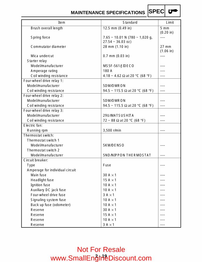
Brush overall length 12.5 mm (0.49 in) 5 mm (0.20 in)
Spring force 7.65 ~ 10.01 N (780 ~ 1,020 g, 27.54 ~ 36.03 oz)
----
Commutator diameter 28 mm (1.10 in) 27 mm (1.06 in)
Mica undercut 0.7 mm (0.03 in) ----Starter relay
Model/manufacturer MS5F-561/JIDECO ----Amperage rating 180 A ----Coil winding resistance 4.18 ~ 4.62 Ω at 20 °C (68 °F) ----
Four-wheel drive relay 1:Model/manufacturer 5DM/OMRON ----Coil winding resistance 94.5 ~ 115.5 Ω at 20 °C (68 °F) ----
Four-wheel drive relay 2:Model/manufacturer 5DM/OMRON ----Coil winding resistance 94.5 ~ 115.5 Ω at 20 °C (68 °F) ----
Four-wheel drive relay 3:Model/manufacturer 29U/MATSUSHITA ----Coil winding resistance 72 ~ 88 Ω at 20 °C (68 °F) ----
Electric fan:Running rpm 3,500 r/min ----
Thermostat switch:Thermostat switch 1
Model/manufacturer 5KM/DENSO ----Thermostat switch 2
Model/manufacturer 5ND/NIPPON THERMOSTAT ----Circuit breaker:
Type Fuse ----Amperage for individual circuit
Main fuse 30 A × 1 ----Headlight fuse 15 A × 1 ----Ignition fuse 10 A × 1 ----Auxiliary DC jack fuse 10 A × 1 ----Four-wheel drive fuse 3 A × 1 ----Signaling system fuse 10 A × 1 ----Back up fuse (odometer) 10 A × 1 ----Reserve 30 A × 1 ----Reserve 15 A × 1 ----Reserve 10 A × 1 ----Reserve 3 A × 1 ----
Item Standard Limit
MAINTENANCE SPECIFICATIONS
Not For Resale www.SmallEngineDiscount.com

2 - 20
SPECEB201000
HOW TO USE THE CONVERSION TABLEAll specification data in this manual are listed inSI and METRIC UNITS.Use this table to convert METRIC unit data toIMPERIAL unit data.Ex.
CONVERSION TABLE
EB202001
GENERAL TORQUE SPECIFICATIONSThis chart specifies torque for standardfasteners with standard I.S.O. pitch threads.Torque specifications for special componentsor assemblies are provided for each chapter ofthis manual. To avoid warpage, tighten multi-fastener assemblies in a crisscross fashion, inprogressive stages, until the specified torque isreached. Unless otherwise specified, torquespecifications require clean, dry threads.Components should be at room temperature.
A: Distance between flatsB: Outside thread diameter
METRIC MULTIPLIER IMPERIAL
** mm × 0.03937 = ** in
2 mm × 0.03937 = 0.08 in
METRIC TO IMPERIAL
Metric unit Multiplier Imperial unit
Torque
m·kgm·kgcm·kgcm·kg
7.23386.7940.07230.8679
ft·lbin·lbft·lbin·lb
Weightkgg
2.2050.03527
lboz
Speed km/hr 0.6214 mph
Distance
kmmmcmmm
0.62143.2811.0940.39370.03937
miftydinin
Volume/Capacity
cc (cm3)cc (cm3)lt (liter)lt (liter)
0.035270.061020.87990.2199
oz (IMP liq.)cu·inqt (IMP liq.)gal (IMP liq.)
Misc.
kg/mmkg/cm2 Centigrade(°C)
55.99714.22349/5+32
lb/inpsi (lb/in2)Fahrenheit (°F)
A(nut)
B(bolt)
General torquespecifications
Nm m•kg ft•lb
10 mm 6 mm 6 0.6 4.3
12 mm 8 mm 15 1.5 11
14 mm 10 mm 30 3.0 22
17 mm 12 mm 55 5.5 40
19 mm 14 mm 85 8.5 61
22 mm 16 mm 130 13.0 94
HOW TO USE THE CONVERSION TABLE/GENERAL TORQUE SPECIFICATIONS
Not For Resale www.SmallEngineDiscount.com
2 - 21
SPEC
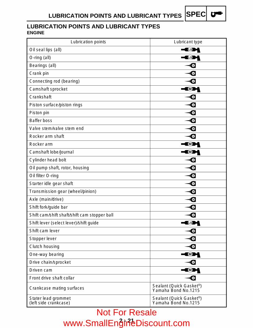
LUBRICATION POINTS AND LUBRICANT TYPESENGINE
Lubrication points Lubricant type
Oil seal lips (all) LS
O-ring (all) LS
Bearings (all) E
Crank pin E
Connecting rod (bearing) E
Camshaft sprocket M
Crankshaft E
Piston surface/piston rings E
Piston pin E
Baffer boss E
Valve stem/valve stem end M
Rocker arm shaft E
Rocker arm M
Camshaft lobe/journal M
Cylinder head bolt E
Oil pump shaft, rotor, housing E
Oil filter O-ring E
Starter idle gear shaft E
Transmission gear (wheel/pinion) M
Axle (main/drive) M
Shift fork/guide bar E
Shift cam/shift shaft/shift cam stopper ball E
Shift lever (select lever)/shift guide LS
Shift cam lever M
Stopper lever E
Clutch housing E
One-way bearing M
Drive chain/sprocket E
Driven cam M
Front drive shaft collar E
Crankcase mating surfaces Sealant (Quick Gasket®)Yamaha Bond No.1215
Stater lead grommet(left side crankcase)
Sealant (Quick Gasket®)Yamaha Bond No.1215
LUBRICATION POINTS AND LUBRICANT TYPES
Not For Resale www.SmallEngineDiscount.com

2 - 22
SPEC
COOLANT FLOW DIAGRAMS1 Radiator 2 Thermo switch3 Fan motor
È To coolant reservoir
COOLANT FLOW DIAGRAMS
Not For Resale www.SmallEngineDiscount.com

2 - 23
SPEC1 Radiator2 Thermostat
È To coolant reservoir
COOLANT FLOW DIAGRAMS
Not For Resale www.SmallEngineDiscount.com
2 - 24
SPEC
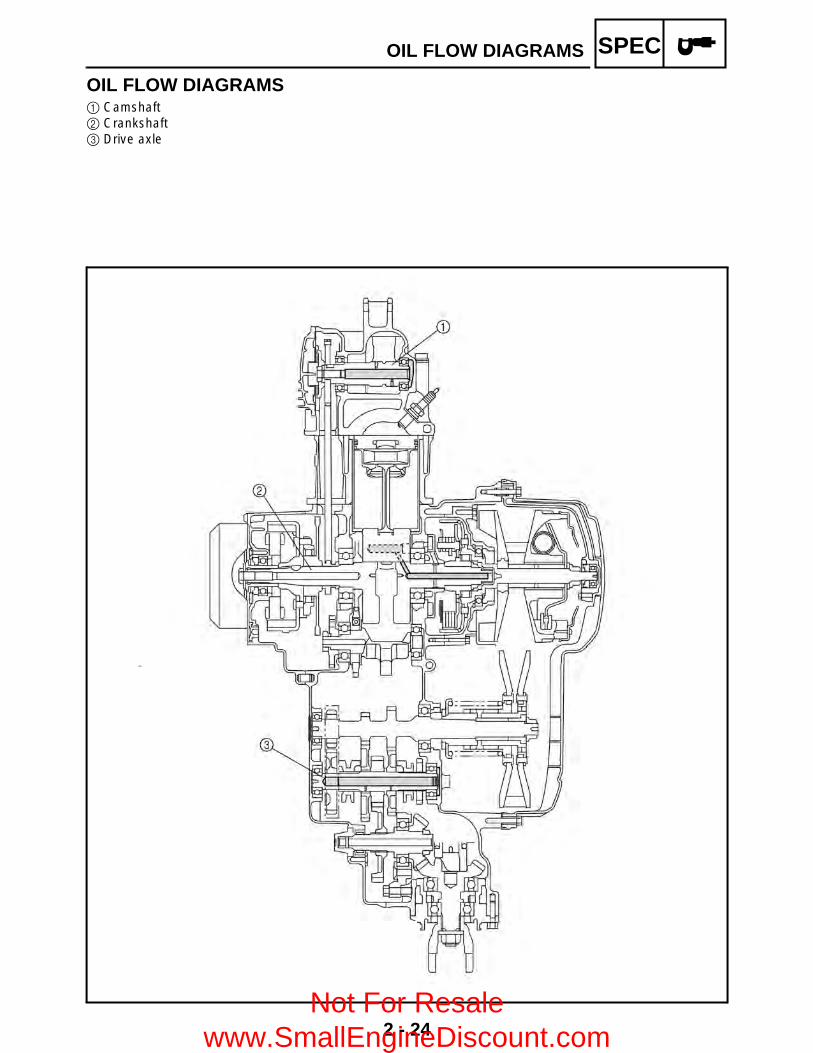
OIL FLOW DIAGRAMS1 Camshaft2 Crankshaft3 Drive axle
OIL FLOW DIAGRAMS
Not For Resale www.SmallEngineDiscount.com
2 - 25
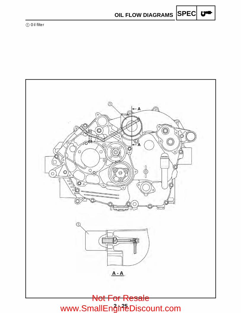
SPEC1 Oil filter
OIL FLOW DIAGRAMS
Not For Resale www.SmallEngineDiscount.com

2 - 26
SPEC1 Oil pump2 Oil strainer
OIL FLOW DIAGRAMS
Not For Resale www.SmallEngineDiscount.com

2 - 27
SPEC
CABLE ROUTING1 Rear brake switch lead2 Starter cable3 Rear brake cable 4 Front brake hose5 On-command four-wheel drive switch and
differential gear lock switch6 Throttle cable7 Handlebar switch8 Handlebar switch lead
9 Main switch lead0 Fan motor breather hoseA Differential gear case breather hose B Sub-wire harness (to gear motor)C On-command four-wheel drive switch and
differential gear lock switch lead
CABLE ROUTING
Not For Resale www.SmallEngineDiscount.com

2 - 28
SPECÈ Fasten the on-command four-wheel drive switch and differential gear lock switch lead behind the
handlebar with a plastic band.É Fasten the starter cable, handlebar switch lead and rear brake switch lead behind the handlebar with a
plastic band.Ê Fasten the handlebar switch lead and rear brake switch lead behind the handlebar with a plastic band.
CABLE ROUTING
Not For Resale www.SmallEngineDiscount.com

2 - 29
SPEC1 Sub-wire harness2 Headlight lead3 Auxiliary DC jack lead4 Four-wheel drive relay 35 Fan motor breather hose6 Differential gear case breather hose7 Coolant reservoir breather hose8 Meter assembly coupler
CABLE ROUTING
Not For Resale www.SmallEngineDiscount.com

2 - 30
SPEC1 Starter cable2 Cylinder head breather hose3 Fuel hose4 Carburetor drain hose5 Coolant reservoir breather hose6 Radiator outlet hose7 Coolant reservoir hose8 Sub-wire harness 9 Differential gear case breather hose0 Thermo switch 2
È Insert the fuel tank breather hose into the hole ofthe handlebar cover.
É Fasten the sub-wire harness, differential gearcase breather hose, coolant reservoir hose,coolant reservoir breather hose, thermo switchlead 2 and fan motor breather hose with a plasticband.
CABLE ROUTING
Not For Resale www.SmallEngineDiscount.com

2 - 31
SPEC1 Cylinder head breather hose2 Final drive gear case breather hose3 Wire harness4 Starter motor lead5 Negative battery lead6 Air filter case check hose7 Water pump breather hose8 Radiator outlet hose9 Starter cable0 Float chamber air vent hoseA Cylinder head breather hose
B Fuel hoseC Low-range switchD High-range switchE Neutral switch leadF Reverse switch leadG Rectifier/regulator
CABLE ROUTING
Not For Resale www.SmallEngineDiscount.com

2 - 32
SPECÈ Fasten the wire harness with a plastic band.É Fasten the starter motor lead, wire harness, negative battery lead, final gear case breather hose,
rectifier/regulator lead, low-range switch lead, high-range switch lead, neutral switch lead, reverse switchlead, speed sensor lead and A.C. magneto lead with a plastic band.
Ê Fasten the wire harness, starter motor lead with a plastic band.Ë Fasten the low-range switch lead, high-range switch lead, neutral switch lead, reverse switch lead, speed
sensor lead, A.C. magneto lead, rectifier/regulator lead and negative battery lead with a plastic band.
CABLE ROUTING
Not For Resale www.SmallEngineDiscount.com

2 - 33
SPEC1 Throttle cable2 Radiator inlet hose3 Spark plug lead4 Main switch5 Wire harness6 Rear brake light switch lead7 Rear brake fluid reservoir hose8 Select lever control cable9 Rear brake cable0 Rear brake hose
È Fasten the radiator inlet hose and spark pluglead with a plastic band.
CABLE ROUTING
Not For Resale www.SmallEngineDiscount.com

2 - 34
SPEC1 Front brake hose2 Float chamber air vent hose3 Throttle cable4 Wire harness5 Final drive gear case breather hose6 Starter cable7 Rear brake cable
CABLE ROUTING
Not For Resale www.SmallEngineDiscount.com

2 - 35
SPEC1 Battery2 Positive battery lead3 Tail/brake light lead4 CDI unit5 Negative battery lead
CABLE ROUTING
Not For Resale www.SmallEngineDiscount.com

2 - 36
SPEC1 Final drive gear case breather hose2 Rear brake hose3 Air filter case check hose
CABLE ROUTING
Not For Resale www.SmallEngineDiscount.com

3 - 1
CHKADJ
INTRODUCTION/PERIODIC MAINTENANCE/LUBRICATION
EB300000
PERIODIC CHECKS AND ADJUSTMENTSINTRODUCTIONThis chapter includes all information necessary to perform recommended checks and adjustments.These preventive maintenance procedures, if followed, will ensure more reliable vehicle operationand a longer service life. The need for costly overhaul work will be greatly reduced. This informationapplies to vehicles already in service as well as to new vehicles that are being prepared for sale. Allservice technicians should be familiar with this entire chapter.
PERIODIC MAINTENANCE/LUBRICATION
ITEM ROUTINE
INITIAL EVERY
Whichever comes first
mile(km)
200(320)
750(1,200)
1,500(2,400)
1,500(2,400)
3,000(4,800)
hours 20 75 150 150 300
Valves*• Check valve clearance.• Adjust if necessary.
Cooling system• Check coolant leakage.• Repair if necessary.• Replace coolant every 24 months.
Spark plug• Check condition. • Adjust gap and clean.• Replace if necessary.
Air filter element• Clean. • Replace if necessary.
Every 20–40 hours(More often in wet or dusty areas.)
Carburetor*• Check and adjust idle speed/starter operation.• Adjust if necessary.
Crankcase breather system*
• Check breather hose for cracks or damage.• Replace if necessary.
Exhaust system*• Check for leakage.• Tighten if necessary.• Replace gasket(s) if necessary.
Spark arrester • Clean.
Fuel line*• Check fuel hose for cracks or damage.• Replace if necessary.
Engine oil • Replace. (Warm engine before draining.)
Engine oil filter cartridge
• Replace.
Engine oil strainer* • Clean.
Final gear oil • Check oil level/oil leakage. • Replace every 12 months.Differential gear oil
Front brake*• Check operation/fluid leakage. (See NOTE page 3-2.)• Correct if necessary.
Rear brake*• Check operation/fluid leakage. (See NOTE page 3-2.)• Correct if necessary.
V-belt*• Check operation. • Check for cracks or damage.
Wheels*• Check balance/damage/runout. • Repair if necessary.
Wheel bearing*• Check bearing assemblies for looseness/damage.• Replace if damaged.
3
Not For Resale www.SmallEngineDiscount.com

3 - 2
CHKADJPERIODIC MAINTENANCE/LUBRICATION
* It is recommended that these items be serviced by a Yamaha dealer.** Lithium-soap-based grease
NOTE: Recommended brake fluid: DOT 4 Brake fluid replacement:1.When disassembling the master cylinder or caliper, replace the brake fluid. Normally check the
brake fluid level and add fluid as required.2.On the inner parts of the master cylinder and caliper, replace the oil seals every two years.3.Replace the brake hoses every four years, or if cracked or damaged.
WARNINGIndicates a potential hazard that could result in serious injury or death.
Front and rear suspension*
• Check operation.• Correct if necessary.
Steering system*• Check operation./Replace if damaged.• Check toe-in./Adjust if necessary.
Drive shaft universal joint*
• Lubricate.**
Engine mount* • Check for cracks or damage.
Front axle boots*• Check operation.• Replace if damaged.
Fittings and fasteners*
• Check all chassis fittings and fasteners.• Correct if necessary.
ITEM ROUTINE
INITIAL EVERY
Whichever comes first
mile(km)
200(320)
750(1,200)
1,500(2,400)
1,500(2,400)
3,000(4,800)
hours 20 75 150 150 300
Not For Resale www.SmallEngineDiscount.com

3 - 3
CHKADJSEAT, CARRIERS, FENDERS AND FUEL TANK
SEAT, CARRIERS, FENDERS AND FUEL TANKSEAT AND SIDE PANELS
Order Job name/Part name Q’ty Remarks
Removing the seat and side panels Remove the parts in the order below.1 Seat 1
NOTE:Pull up the seat lock lever, then pull up onthe rear of the seat.
2 Fuel tank side panel (left) 13 Fuel tank side panel (right) 14 Engine side panel 15 Engine side cover 1
For installation, reverse the removal procedure.
Not For Resale www.SmallEngineDiscount.com
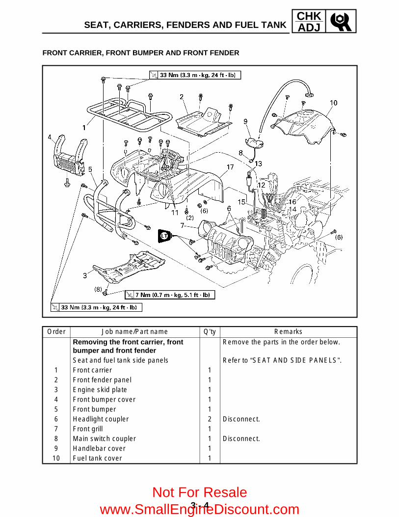
3 - 4
CHKADJSEAT, CARRIERS, FENDERS AND FUEL TANK
FRONT CARRIER, FRONT BUMPER AND FRONT FENDER
Order Job name/Part name Q’ty Remarks
Removing the front carrier, front bumper and front fender
Remove the parts in the order below.
Seat and fuel tank side panels Refer to “SEAT AND SIDE PANELS”.1 Front carrier 12 Front fender panel 13 Engine skid plate 14 Front bumper cover 15 Front bumper 16 Headlight coupler 2 Disconnect.7 Front grill 18 Main switch coupler 1 Disconnect.9 Handlebar cover 1
10 Fuel tank cover 1
Not For Resale www.SmallEngineDiscount.com
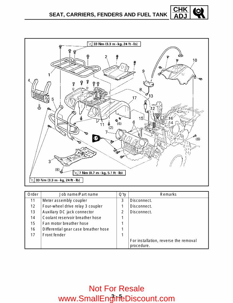
3 - 5
CHKADJSEAT, CARRIERS, FENDERS AND FUEL TANK
Order Job name/Part name Q’ty Remarks
11 Meter assembly coupler 3 Disconnect.12 Four-wheel drive relay 3 coupler 1 Disconnect.13 Auxiliary DC jack connector 2 Disconnect.14 Coolant reservoir breather hose 115 Fan motor breather hose 116 Differential gear case breather hose 117 Front fender 1
For installation, reverse the removal procedure.
Not For Resale www.SmallEngineDiscount.com

3 - 6
CHKADJSEAT, CARRIERS, FENDERS AND FUEL TANK
REAR CARRIER AND REAR FENDER
Order Job name/Part name Q’ty Remarks
Removing the rear carrier and rear fender
Remove the parts in the order below.
Seat and fuel tank side panels Refer to “SEAT AND SIDE PANELS”.Fuel tank Refer to “FUEL TANK”.
1 Rear carrier 12 Battery holding bracket 13 Battery lead cover 14 Battery lead 2 Disconnect.
CAUTION:First disconnect the negative lead,then disconnect the positive lead.
5 Battery6 Starter relay ground lead 1 Disconnect.7 Tail/brake light connector 3 Disconnect.
Not For Resale www.SmallEngineDiscount.com

3 - 7
CHKADJSEAT, CARRIERS, FENDERS AND FUEL TANK
Order Job name/Part name Q’ty Remarks
8 CDI unit 19 Wire harness 1
10 Rear fender 1For installation, reverse the removal procedure.
Not For Resale www.SmallEngineDiscount.com

3 - 8
CHKADJSEAT, CARRIERS, FENDERS AND FUEL TANK
FUEL TANK
Order Job name/Part name Q’ty RemarksRemoving the fuel tank Remove the parts in the order below.Seat and fuel tank side panels Refer to “SEAT AND SIDE PANELS”.Fuel tank cover Refer to “FRONT CARRIER, FRONT
BUMPER AND FRONT FENDER”.1 Fuel hose 1 NOTE:
Before disconnecting the fuel hose, turnthe fuel cock to “OFF”.
2 Fuel cock lever 13 Fuel tank 1 NOTE:
When installing the fuel tank, pass thefuel tank breather hose through the holeof the handlebar protector.
4 Float chamber air vent hose 15 Plastic band 46 Rubber cover 1
For installation, reverse the removal procedure.Not For Resale
www.SmallEngineDiscount.com

3 - 9
CHKADJFOOTREST BOARDS
FOOTREST BOARDS
Order Job name/Part name Q’ty Remarks
Removing the footrest boards Remove the parts in the order below.Fuel tank side panels Refer to “SEAT AND SIDE PANELS”.
1 Left footrest board 12 Right footrest board 13 Footrest bracket 4
For installation, reverse the removal procedure.
Not For Resale www.SmallEngineDiscount.com

3 - 10
CHKADJADJUSTING THE VALVE CLEARANCE
ENGINEADJUSTING THE VALVE CLEARANCE
NOTE: The valve clearance must be adjusted when
the engine is cool to the touch. Adjust the valve clearance when the piston is
at the Top Dead Center (T.D.C.) on thecompression stroke.
1.Remove: Seat Front carrier Front fender Fuel tank
Refer to “SEAT, CARRIERS, FENDERSAND FUEL TANK”.
2.Remove: Tappet cover (intake) 1 Tappet cover (exhaust) 2 3.Disconnect: Spark plug cap 3 4.Remove: Spark plug
5.Remove: Recoil starter 1
6.Remove: Timing plug 1
Not For Resale www.SmallEngineDiscount.com

3 - 11
CHKADJADJUSTING THE VALVE CLEARANCE
7.Check: Valve clearance
Out of specification → Adjust.
*****************************************************Checking steps: Turn the crankshaft counterclockwise with a
wrench. Align the “T” mark 1 on the rotor with the
stationary pointer 2 on the crankcase cover.When the “T” mark is aligned with thestationary pointer, the piston is at the TopDead Center (T.D.C.).
NOTE: When the piston is at the Top Dead Center
(T.D.C.) on the compression stroke, thereshould be clearance between the valve stemtips and their respective rocker arm adjustingscrews.
If there is no clearance, rotate the crankshaftcounterclockwise one turn.
Measure the valve clearance using a feelergauge 3.
*****************************************************
Valve clearance (cold):Intake:
0.06 ~ 0.10 mm (0.0024 ~ 0.0039 in)
Exhaust:0.16 ~ 0.20 mm (0.0063 ~ 0.0079 in)
Not For Resale www.SmallEngineDiscount.com
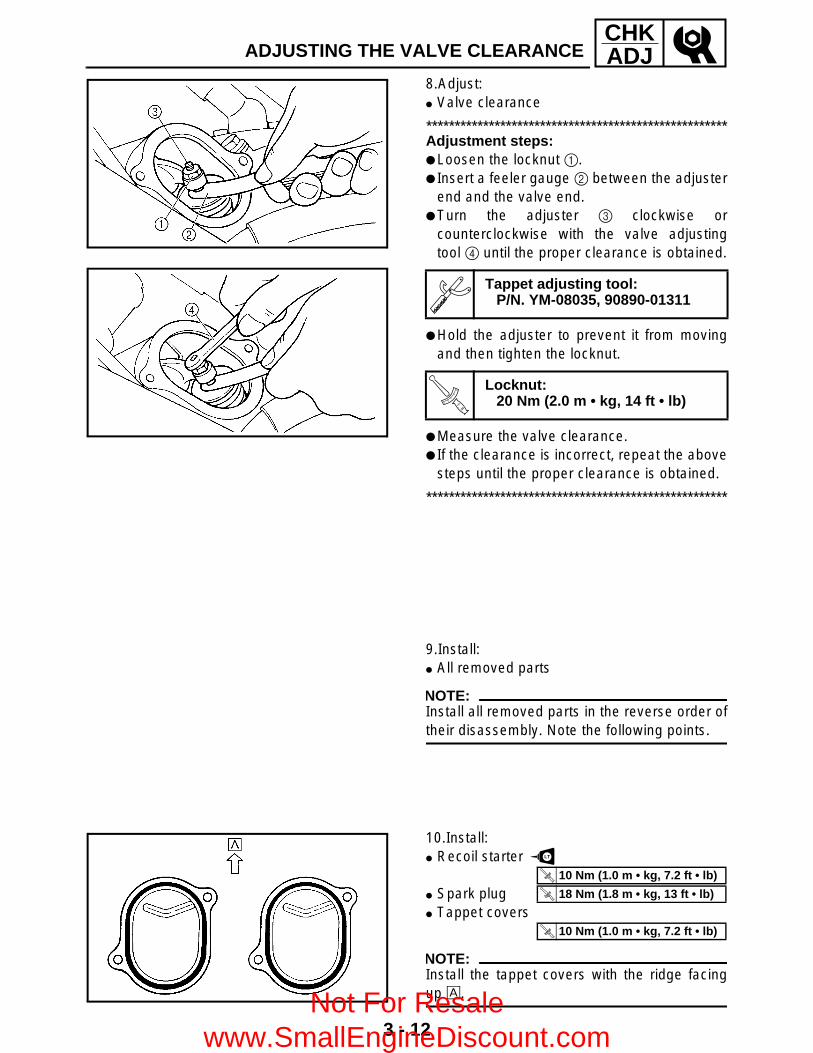
3 - 12
CHKADJADJUSTING THE VALVE CLEARANCE
8.Adjust: Valve clearance
*****************************************************Adjustment steps: Loosen the locknut 1. Insert a feeler gauge 2 between the adjuster
end and the valve end. Turn the adjuster 3 clockwise or
counterclockwise with the valve adjustingtool 4 until the proper clearance is obtained.
Hold the adjuster to prevent it from movingand then tighten the locknut.
Measure the valve clearance. If the clearance is incorrect, repeat the above
steps until the proper clearance is obtained.
*****************************************************
Tappet adjusting tool:P/N. YM-08035, 90890-01311
T R..
Locknut:20 Nm (2.0 m • kg, 14 ft • lb)
9.Install: All removed parts
NOTE:Install all removed parts in the reverse order oftheir disassembly. Note the following points.
10.Install: Recoil starter
Spark plug Tappet covers
NOTE:Install the tappet covers with the ridge facingup È.
LT
T R..
10 Nm (1.0 m • kg, 7.2 ft • lb)
T R..
18 Nm (1.8 m • kg, 13 ft • lb)
T R..
10 Nm (1.0 m • kg, 7.2 ft • lb)
Not For Resale www.SmallEngineDiscount.com
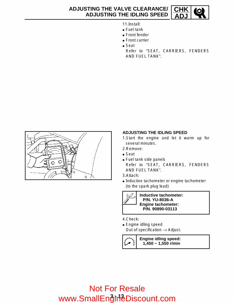
3 - 13
CHKADJ
ADJUSTING THE VALVE CLEARANCE/ADJUSTING THE IDLING SPEED
11.Install: Fuel tank Front fender Front carrier Seat
Refer to “SEAT, CARRIERS, FENDERSAND FUEL TANK”.
ADJUSTING THE IDLING SPEED 1.Start the engine and let it warm up for
several minutes.2.Remove: Seat Fuel tank side panels
Refer to “SEAT, CARRIERS, FENDERSAND FUEL TANK”.
3.Attach: Inductive tachometer or engine tachometer
(to the spark plug lead)
4.Check: Engine idling speed
Out of specification → Adjust.
Inductive tachometer:P/N. YU-8036-A
Engine tachometer:P/N. 90890-03113
Engine idling speed:1,450 ~ 1,550 r/min
Not For Resale www.SmallEngineDiscount.com
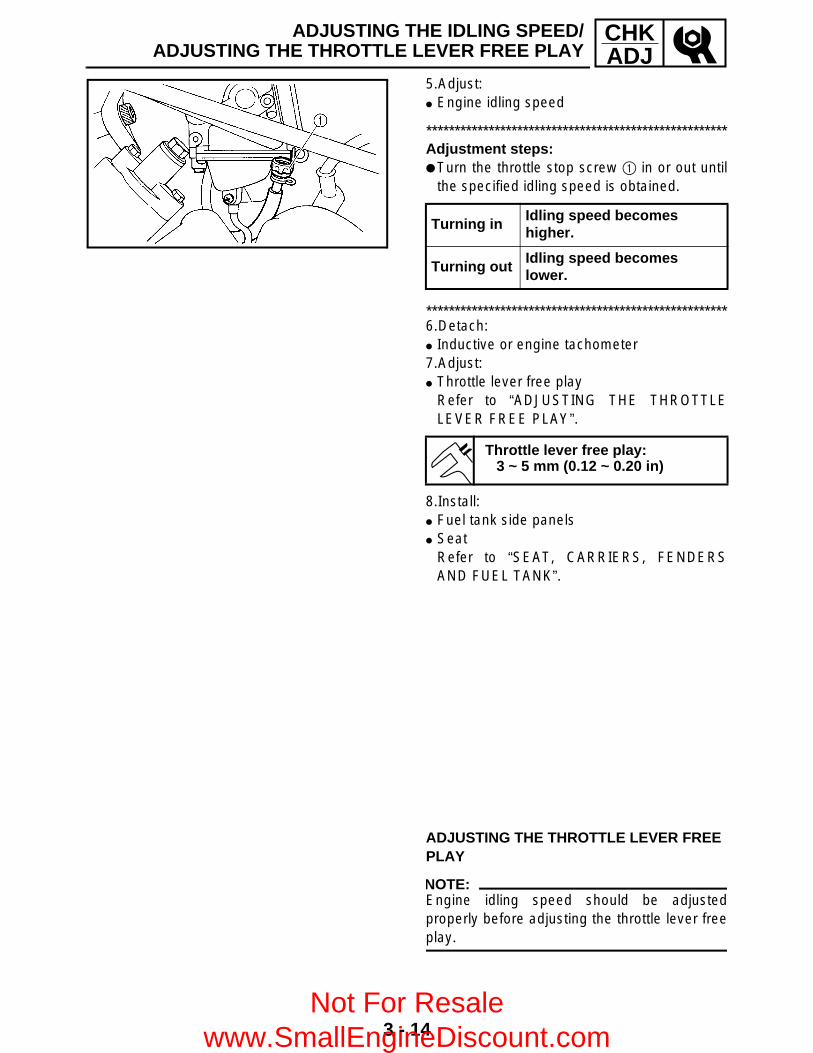
3 - 14
CHKADJ
ADJUSTING THE IDLING SPEED/ADJUSTING THE THROTTLE LEVER FREE PLAY
5.Adjust: Engine idling speed
*****************************************************Adjustment steps: Turn the throttle stop screw 1 in or out until
the specified idling speed is obtained.
*****************************************************6.Detach: Inductive or engine tachometer7.Adjust: Throttle lever free play
Refer to “ADJUSTING THE THROTTLELEVER FREE PLAY”.
8.Install: Fuel tank side panels Seat
Refer to “SEAT, CARRIERS, FENDERSAND FUEL TANK”.
Turning inIdling speed becomes higher.
Turning out Idling speed becomes lower.
Throttle lever free play:3 ~ 5 mm (0.12 ~ 0.20 in)
ADJUSTING THE THROTTLE LEVER FREE PLAY
NOTE:Engine idling speed should be adjustedproperly before adjusting the throttle lever freeplay.
Not For Resale www.SmallEngineDiscount.com

3 - 15
CHKADJADJUSTING THE THROTTLE LEVER FREE PLAY
1.Check: Throttle lever free play a
Out of specification → Adjust.
Throttle lever free play:3 ~ 5 mm (0.12 ~ 0.20 in)
2.Remove: Seat Fuel tank side panel (right)
Refer to “SEAT, CARRIERS, FENDERSAND FUEL TANK”.
3.Adjust: Throttle lever free play
*****************************************************Adjustment steps:First step: Pull back the adjuster cover 1. Loosen the locknut 2 on the carburetor side. Turn the adjuster 3 in or out until the correct
free play is obtained.
Tighten the locknut 2. Push in the adjuster cover 1.
NOTE:If the free play cannot be adjusted here, adjustit at the throttle lever side of the cable.
Turning in Free play is increased.
Turning out Free play is decreased.
Not For Resale www.SmallEngineDiscount.com
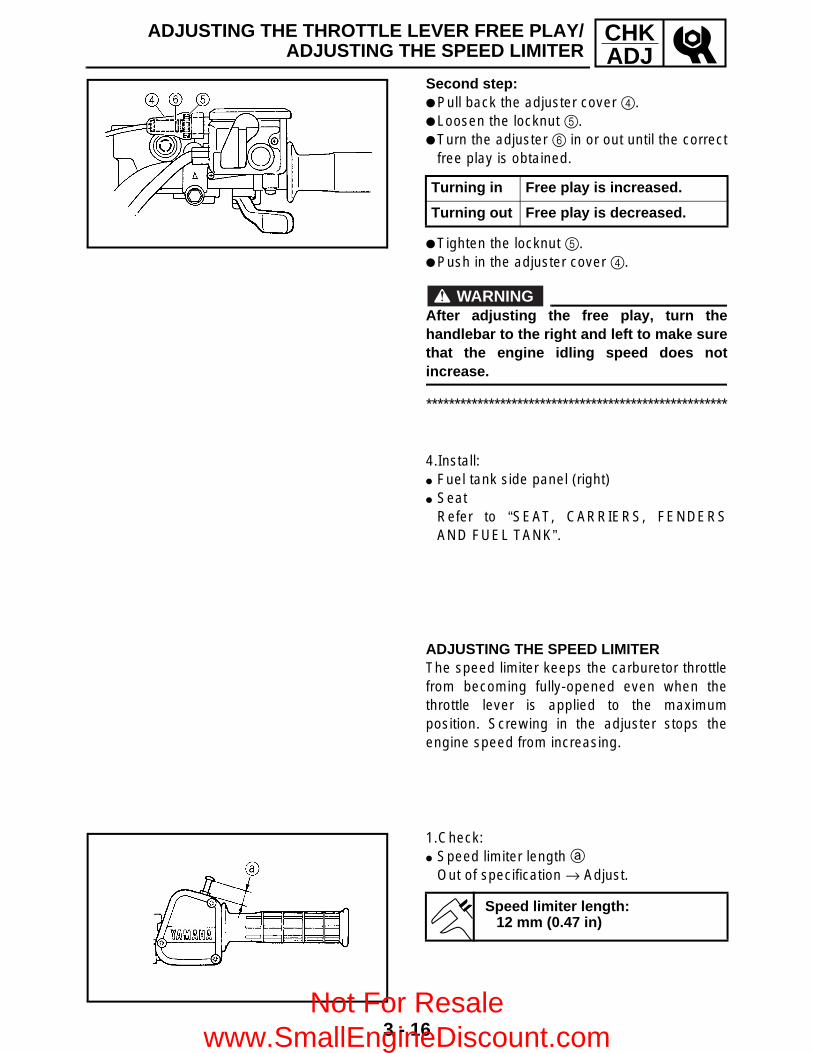
3 - 16
CHKADJ
ADJUSTING THE THROTTLE LEVER FREE PLAY/ADJUSTING THE SPEED LIMITER
Second step: Pull back the adjuster cover 4. Loosen the locknut 5. Turn the adjuster 6 in or out until the correct
free play is obtained.
Tighten the locknut 5. Push in the adjuster cover 4.
WARNINGAfter adjusting the free play, turn thehandlebar to the right and left to make surethat the engine idling speed does notincrease.
*****************************************************
Turning in Free play is increased.
Turning out Free play is decreased.
4.Install: Fuel tank side panel (right) Seat
Refer to “SEAT, CARRIERS, FENDERSAND FUEL TANK”.
ADJUSTING THE SPEED LIMITER The speed limiter keeps the carburetor throttlefrom becoming fully-opened even when thethrottle lever is applied to the maximumposition. Screwing in the adjuster stops theengine speed from increasing.
1.Check: Speed limiter length a
Out of specification → Adjust.
Speed limiter length:12 mm (0.47 in)
Not For Resale www.SmallEngineDiscount.com

3 - 17
CHKADJ
ADJUSTING THE SPEED LIMITER/ADJUSTING THE STARTER CABLE
2.Adjust: Speed limiter length
*****************************************************Speed limiter length adjustment steps: Loosen the locknut 1. Turn the adjuster 2 in or out until the
specified speed limiter length is obtained.
Tighten the locknut.
WARNING Particularly for a beginner rider, the
speed limiter should be screwed incompletely. Screw it out little by little astheir riding technique improves. Neverremove the speed limiter for a beginningrider.
For proper throttle lever operation do notturn out the adjuster more than 12 mm(0.47 in). Also, always adjust the throttlelever free play to 3 ~ 5 mm (0.12 ~ 0.20 in).
*****************************************************
Turning in Speed limiter length is decreased.
Turning out Speed limiter length is increased.
ADJUSTING THE STARTER CABLE1.Remove: Seat Fuel tank side panel (left)
Refer to “SEAT, CARRIERS, FENDERSAND FUEL TANK”.
Not For Resale www.SmallEngineDiscount.com

3 - 18
CHKADJADJUSTING THE STARTER CABLE
2.Adjust:
*****************************************************Adjustment steps: Disconnect the starter cable 1 from the
carburetor body.
NOTE:Do not remove the starter plunger 2 from thestarter cable.
Measure the starter plunger stroke distancea of the starter lever 3 fully close to fullyopen position. If the distance is out ofspecification adjust it as described below.
È Fully closed positionÉ Fully open position Pull back the boot 4. Loosen the locknut 5. Turn the adjuster 6 in or out until the correct
free play is obtained.
Tighten the locknut 5. Push in the boot 4. Connect the starter cable to the carburetor.
WARNINGAfter adjusting the cable, turn thehandlebar to right and left, and make surethat the engine idling speed does notincrease.
*****************************************************
Starter plunger stroke distance:15 mm (0.59 in)
Turning in Free play increased.
Turning out Free play decreased.
3.Install: Fuel tank side panel (left) Seat
Refer to “SEAT, CARRIERS, FENDERSAND FUEL TANK”.
Not For Resale www.SmallEngineDiscount.com

3 - 19
CHKADJCHECKING THE SPARK PLUG
CHECKING THE SPARK PLUG 1.Remove: Seat Fuel tank side panel (right)
Refer to “SEAT, CARRIERS, FENDERSAND FUEL TANK”.
2.Remove: Spark plug3.Check: Spark plug type
Incorrect → Replace.
Standard spark plug:DR8EA/NGK
4.Check: Electrode 1
Wear/damage → Replace. Insulator 2
Abnormal color → Replace.Normal color is a medium-to-light tan color.
5.Clean the spark plug with a spark plugcleaner or wire brush.
6.Measure: Plug gap a
Use a wire gauge or feeler gauge.Out of specification → Regap.
7.Tighten: Spark plug
NOTE:Before installing a spark plug, clean the gasketsurface and plug surface.
8.Install: Fuel tank side panel (right) Seat
Refer to “SEAT, CARRIERS, FENDERSAND FUEL TANK”.
Spark plug gap:0.6 ~ 0.7 mm (0.024 ~ 0.028 in)
T R..
18 Nm (1.8 m • kg, 13 ft • lb)
Not For Resale www.SmallEngineDiscount.com

3 - 20
CHKADJCHECKING THE IGNITION TIMING
CHECKING THE IGNITION TIMING
NOTE:Engine idling speed and throttle cable free playshould be adjusted properly before checkingthe ignition timing.
1.Remove: Seat Fuel tank side panel (right)
Refer to “SEAT, CARRIERS, FENDERSAND FUEL TANK”.
2.Attach: Inductive tachometer or engine tachometer Timing light
(to spark plug lead)
3.Check: Ignition timing
*****************************************************Checking steps: Warm up the engine and keep it at the
specified speed.
Remove the recoil starter 1. Remove the timing plug 2. Visually check the stationary pointer 3 to
verify it is within the required firing range 4indicated on the flywheel.Incorrect firing range → Check the pulser coilassembly.
Install the timing plug. Install the recoil starter.
*****************************************************
Inductive tachometer:P/N. YU-8036-A
Engine tachometer:P/N. 90890-03113
Timing light:P/N. YM-33277-A, 90890-03141
Engine speed:1,450 ~ 1,550 r/min
T R..
Recoil starter bolt:10 Nm (1.0 m • kg, 7.2 ft • Ib)LOCTITE®
Not For Resale www.SmallEngineDiscount.com

3 - 21
CHKADJ
4.Detach: Timing light Inductive tachometer or engine tachometer5.Install: Seat Fuel tank side panel (right)
Refer to “SEAT, CARRIERS, FENDERSAND FUEL TANK”.
MEASURING THE COMPRESSION PRESSURE
NOTE:Insufficient compression pressure will result ina loss of performance.
1.Check: Valve clearance
Out of specification → Adjust.Refer to “ADJUSTING THE VALVECLEARANCE”.
2.Start the engine and let it warm up forseveral minutes.
3.Stop the engine.4.Remove: Seat Fuel tank side panel (right)
Refer to “SEAT, CARRIERS, FENDERSAND FUEL TANK”.
5.Remove: Spark plug6.Attach: Adapter Compression gauge 1
Compression gauge:P/N. YU-33223, 90890-03081
Adapter:P/N. YU-33223-3, 90890-04082
CHECKING THE IGNITION TIMING/MEASURING THE COMPRESSION PRESSURE
Not For Resale www.SmallEngineDiscount.com

3 - 22
CHKADJMEASURING THE COMPRESSION PRESSURE
7.Measure: Compression pressure
Above the maximum pressure:Check the cylinder head, valve surfaces, andpiston crown for carbon deposits.Below the minimum pressure:Squirt a few drops of oil into the affectedcylinder and measure again.
Refer to the table below.
*****************************************************Measurement steps: Crank over the engine with the electric
starter (be sure the battery is fully charged)with the throttle wide-open until thecompression reading on the gaugestabilizes.
WARNINGWhen cranking the engine, ground thespark plug lead to prevent sparking.
*****************************************************
Compression pressure (with oil introduced into cylinder)
Reading Diagnosis
Higher than without oil Worn or damaged pistons
Same as without oil
Defective ring(s), valves, cylinder head gasket or piston is possible.
Compression pressure (at sea level):
Standard:1,270 kPa (12.7 kg/cm2, 181 psi)
Minimum:1,105 kPa (11.1 kg/cm2, 158 psi)
Maximum:1,422 kPa (14.2 kg/cm2, 202 psi)
8.Install: Spark plug9.Remove: Fuel tank side panel (right) Seat
Refer to “SEAT, CARRIERS, FENDERSAND FUEL TANK”.
T R..
18 Nm (1.8 m • kg, 13 ft • lb)
Not For Resale www.SmallEngineDiscount.com
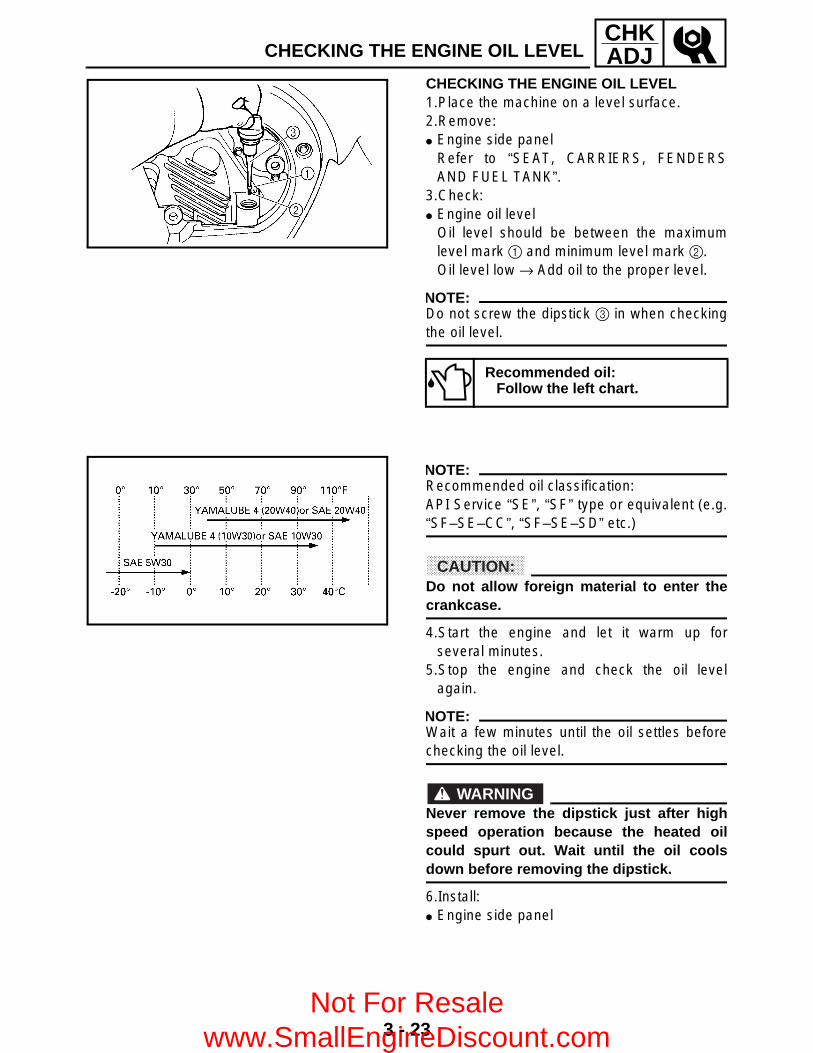
3 - 23
CHKADJCHECKING THE ENGINE OIL LEVEL
CHECKING THE ENGINE OIL LEVEL 1.Place the machine on a level surface.2.Remove: Engine side panel
Refer to “SEAT, CARRIERS, FENDERSAND FUEL TANK”.
3.Check: Engine oil level
Oil level should be between the maximumlevel mark 1 and minimum level mark 2.Oil level low → Add oil to the proper level.
NOTE:Do not screw the dipstick 3 in when checkingthe oil level.
Recommended oil:Follow the left chart.
NOTE:Recommended oil classification:API Service “SE”, “SF” type or equivalent (e.g.“SF–SE–CC”, “SF–SE–SD” etc.)
CAUTION:Do not allow foreign material to enter thecrankcase.
4.Start the engine and let it warm up forseveral minutes.
5.Stop the engine and check the oil levelagain.
NOTE:Wait a few minutes until the oil settles beforechecking the oil level.
WARNINGNever remove the dipstick just after highspeed operation because the heated oilcould spurt out. Wait until the oil coolsdown before removing the dipstick.
6.Install: Engine side panel
Not For Resale www.SmallEngineDiscount.com

3 - 24
CHKADJCHANGING THE ENGINE OIL
CHANGING THE ENGINE OIL1.Start the engine and let it warm up for
several minutes.2.Stop the engine and place an oil pan under
the engine.3.Remove: Seat Fuel tank side panel (left) Engine side cover
Refer to “SEAT, CARRIERS, FENDERSAND FUEL TANK”.
4.Remove: Engine oil filler plug (dipstick) 1
5.Remove: Engine oil drain bolt 1
Drain the engine oil. Oil strainer cover 2 Compression spring 3 Oil strainer 4 6.Clean: Oil strainer
7.If the oil filter cartridge is also to be replaced,perform the following procedure.
*****************************************************Replacement steps: Remove the oil filter cartridge 1 with an oil
filter wrench 2.
Oil filter wrench:P/N. YU-38411, 90890-01426
Not For Resale www.SmallEngineDiscount.com
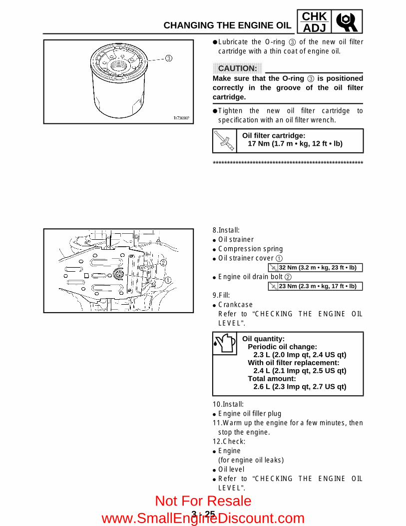
3 - 25
CHKADJ
Lubricate the O-ring 3 of the new oil filtercartridge with a thin coat of engine oil.
CAUTION:Make sure that the O-ring 3 is positionedcorrectly in the groove of the oil filtercartridge.
Tighten the new oil filter cartridge tospecification with an oil filter wrench.
*****************************************************
T R..
Oil filter cartridge:17 Nm (1.7 m • kg, 12 ft • lb)
8.Install: Oil strainer Compression spring Oil strainer cover 1
Engine oil drain bolt 2
9.Fill: Crankcase
Refer to “CHECKING THE ENGINE OILLEVEL”.
10.Install: Engine oil filler plug11.Warm up the engine for a few minutes, then
stop the engine.12.Check: Engine
(for engine oil leaks) Oil level Refer to “CHECKING THE ENGINE OIL
LEVEL”.
Oil quantity:Periodic oil change:
2.3 L (2.0 Imp qt, 2.4 US qt)With oil filter replacement:
2.4 L (2.1 Imp qt, 2.5 US qt)Total amount:
2.6 L (2.3 Imp qt, 2.7 US qt)
T R..
32 Nm (3.2 m • kg, 23 ft • lb)
T R..
23 Nm (2.3 m • kg, 17 ft • lb)
CHANGING THE ENGINE OIL
Not For Resale www.SmallEngineDiscount.com

3 - 26
CHKADJ
CHANGING THE ENGINE OIL/CLEANING THE AIR FILTER
13.Check: Engine oil pressure
***************************************************** Slightly loosen the oil gallery bolt 1. Start the engine and keep it idling until
engine oil starts to seep from the oil gallerybolt. If no engine oil comes out after oneminute, turn the engine off so that it will notseize.
Check the engine oil passages, the oil filtercartridge and the oil pump for damage orleakage. Refer to “CRANKCASE” inCHAPTER 4.
Start the engine after solving the problem(-s)and check the engine oil pressure again.
Tighten the oil gallery bolt to specification.
*****************************************************14.Install: Engine side cover Fuel tank side panel (left) Seat
Refer to “SEAT, CARRIERS, FENDERSAND FUEL TANK”.
Oil gallery bolt:7 Nm (0.7 m • kg, 5.1 ft • lb)
CLEANING THE AIR FILTER
NOTE:There is a check hose 1 at the bottom of theair filter case. If dust and/or water collects inthis hose, clean the air filter element and airfilter case.
Not For Resale www.SmallEngineDiscount.com

3 - 27
CHKADJCLEANING THE AIR FILTER
1.Remove: Seat2.Remove: Air filter case cover 1
3.Remove: Air filter element assembly 1 Air filter element cap Air filter element
2 Air filter element cap3 Air filter element
CAUTION:Never operate the engine with the air filterelement removed. This will allow unfilteredair to enter, causing rapid wear andpossible engine damage. Additionally,operation without the filter element willaffect carburetor tuning with subsequentpoor performance and possible engineoverheating.
4.Check: Air filter element
Damaged → Replace.
Not For Resale www.SmallEngineDiscount.com

3 - 28
CHKADJCLEANING THE AIR FILTER
5.Clean: Air filter element
*****************************************************Cleaning steps: Wash the element gently, but thoroughly in
solvent.
WARNINGUse a cleaning solvent which is designedto clean parts only. Never use gasoline orlow flash point solvents as they may causea fire or explosion.
Squeeze the excess solvent out of theelement and let it dry.
CAUTION:Do not twist or wring out the element. Thiscould damage the foam material.
Apply engine oil to the element. Squeeze out the excess oil.
NOTE:The element should be wet but not dripping.
*****************************************************
6.Install: Air filter element Air filter case cover
NOTE:To prevent air leaks make sure that the sealingsurface of the element matches the sealingsurface of the case.
SeatRefer to “SEAT, CARRIERS, FENDERSAND FUEL TANK”.
Not For Resale www.SmallEngineDiscount.com

3 - 29
CHKADJCHECKING THE COOLANT LEVEL
CHECKING THE COOLANT LEVEL1.Place the machine on a level surface.2.Remove: Seat Fuel tank side panel (left)
3.Check: Coolant level
The coolant level should be between theminimum level mark a and maximum levelmark b.Below the minimum level mark → Add therecommended coolant to the proper level.
CAUTION: Adding water instead of coolant lowers
the antifreeze content of the coolant. Ifwater is used instead of coolant, checkand if necessary, correct the antifreezeconcentration of the coolant.
Use only distilled water. However, softwater may be used if distilled water is notavailable.
4.Start the engine, warm it up for severalminutes, and then turn it off.
5.Check: Coolant level
NOTE:Before checking the coolant level, wait a fewminutes until the coolant has settled.
6.Install: Fuel tank side panel (left) Seat
Refer to “SEAT, CARRIERS, FENDERSAND FUEL TANK”.
Not For Resale www.SmallEngineDiscount.com

3 - 30
CHKADJCHANGING THE COOLANT
CHANGING THE COOLANT 1.Remove: Seat Fuel tank side panel (left) Engine side cover Front carrier Engine skid plate Front fender
Refer to “SEAT, CARRIERS, FENDERSAND FUEL TANK”.
Left footrest boardRefer to “FOOTREST BOARDS”.
2.Remove: Plastic band 1 Coolant reservoir bolts 2 Coolant reservoir cap 3 3.Disconnect: Coolant reservoir breather hose 4
4.Drain: Coolant
(from the coolant reservoir)5.Connect: Coolant reservoir breather hose6.Install: Coolant reservoir bolts Plastic band
7.Remove: Radiator cap 1
WARNINGA hot radiator is under pressure. Therefore,do not remove the radiator cap when theengine is hot. Scalding hot fluid and steammay be blown out, which could causeserious injury. When the engine hascooled, open the radiator cap as follows:Place a thick rag or a towel over theradiator cap and slowly turn the radiatorcap counterclockwise toward the detent toallow any residual pressure to escape.When the hissing sound has stopped, turnthe radiator cap counterclockwise whilepressing down on it and then remove it.
Not For Resale www.SmallEngineDiscount.com

3 - 31
CHKADJCHANGING THE COOLANT
8.Remove: Coolant drain bolt (cylinder) 1
(along with the copper washer) Coolant drain bolt (water pump) 2
(along with the copper washer)9.Drain: Coolant
10.Check: Copper washer 1 Coolant drain bolt 2
Damage → Replace.11.Install: Coolant drain bolt (water pump)
Coolant drain bolt (cylinder)
T R..
10 Nm (1.0 m • kg, 7.2 ft • lb)
T R..
10 Nm (1.0 m • kg, 7.2 ft • lb)
12.Fill: Cooling system
(with the specified amount of therecommended coolant)
Handling notes for coolantCoolant is potentially harmful and should behandled with special care.
WARNING If coolant splashes in your eyes,
thoroughly wash them with water andconsult a doctor.
If coolant splashes on your clothes,quickly wash it away with water and thenwith soap and water.
If coolant is swallowed, induce vomitingand get immediate medical attention.
Recommended antifreezeHigh-quality ethylene glycolantifreeze containing corrosioninhibitors for aluminum engines
Mixing ratio1:1 (antifreeze:water)
QuantityTotal amount
1.32 L (1.16 Imp qt, 1.40 US qt)Coolant reservoir capacity
0.39 L (0.34 Imp qt, 0.41 US qt)
Not For Resale www.SmallEngineDiscount.com

3 - 32
CHKADJCHANGING THE COOLANT
CAUTION: Adding water instead of coolant lowers
the antifreeze content of the coolant. Ifwater is used instead of coolant, check,and if necessary, correct the antifreezeconcentration of the coolant.
Use only distilled water. However, softwater may be used if distilled water is notavailable.
If coolant comes into contact with paintedsurfaces, immediately wash them withwater.
Do not mix different types of antifreeze.
13.Install: Radiator cap
14.Fill: Coolant reservoir
(with the recommended coolant to themaximum level mark a)
15.Install: Coolant reservoir cap16.Start the engine, warm it up for several
minutes, and then turn it off.17.Check: Coolant level
Refer to “CHECKING THE COOLANTLEVEL”.
NOTE:Before checking the coolant level, wait a fewminutes until the coolant has settled.
18.Install: Left footrest board
Refer to “FOOTREST BOARDS”. Front fender Engine skid plate Front carrier Engine side cover Fuel tank side panel (left) Seat
Refer to “SEAT, CARRIERS, FENDERSAND FUEL TANK”.
Not For Resale www.SmallEngineDiscount.com

3 - 33
CHKADJ
COOLANT TEMPERATURE WARNING LIGHT CHECK/CHECKING THE V-BELT
COOLANT TEMPERATURE WARNING LIGHT CHECK1 Coolant temperature warning light
Turn the main switch “ON” and the engine stop switch to “ ”.
Coolant temperature warning light checking method
Coolant temperature warning light does not come on.
Push start switch with transmission in “neutral”.
Coolant temperature warning light comes on momentarily.
Coolant temperature warning light does not come on.
Coolant temperature warning light comes on.
Coolant temperature and electrical circuit are OK. Go ahead with riding.
Ask a Yamaha dealer to check the electrical circuit.
CHECKING THE V-BELT 1.Remove: Right footrest board Crankcase cover (right)
Refer to “PRIMARY AND SECONDARYSHEAVES” in CHAPTER 4.
2.Check: V-belt 1
Cracks/wear/scaling/chipping → Replace.Oil/grease → Check primary sheave andsecondary sheave.
3.Measure: V-belt width 2
Out of specification → Replace.
V-belt width:30.7 mm (1.21 in)<Limit:> 27.6 mm (10.9 in)
Not For Resale www.SmallEngineDiscount.com
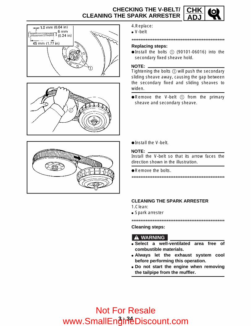
3 - 34
CHKADJ
CHECKING THE V-BELT/CLEANING THE SPARK ARRESTER
4.Replace: V-belt
*****************************************************Replacing steps: Install the bolts 1 (90101-06016) into the
secondary fixed sheave hold.
NOTE:Tightening the bolts 1 will push the secondarysliding sheave away, causing the gap betweenthe secondary fixed and sliding sheaves towiden.
Remove the V-belt 1 from the primarysheave and secondary sheave.
Install the V-belt.
NOTE:Install the V-belt so that its arrow faces thedirection shown in the illustration.
Remove the bolts.
*****************************************************
CLEANING THE SPARK ARRESTER 1.Clean: Spark arrester
*****************************************************Cleaning steps:
WARNING Select a well-ventilated area free of
combustible materials. Always let the exhaust system cool
before performing this operation. Do not start the engine when removing
the tailpipe from the muffler.
Not For Resale www.SmallEngineDiscount.com

3 - 35
CHKADJCLEANING THE SPARK ARRESTER
Remove the bolt 1. Remove the tailpipe 2 by pulling it out of the
muffler. Tap the tailpipe lightly with a soft-face
hammer or suitable tool, then use a wirebrush to remove any carbon deposits fromthe spark arrester portion of the tailpipe andthe inner contact surfaces of the muffler.
Insert the tailpipe 2 into the muffler andalign the bolt holes.
Insert the bolt 1 and tighten it.
*****************************************************
Not For Resale www.SmallEngineDiscount.com

3 - 36
CHKADJADJUSTING THE REAR BRAKE
CHASSISADJUSTING THE REAR BRAKE
WARNINGAlways adjust both the brake pedal and therear brake lever whenever adjusting therear brake.
1.Check: Rear brake lever free play a
Out of specification → Adjust.
Rear brake lever free play:0.5 ~ 2 mm (0.02 ~ 0.08 in)
2.Check: Rear brake pedal height a
Out of specification → Adjust.
1 Brake pedal2 Footrest
Rear brake pedal height:70 ~ 80 mm (2.76 ~ 3.15 in)
3.Adjust: Rear brake lever free play Rear brake pedal height
*****************************************************Adjustment steps: Loosen the locknut (handlebar) 1 and fully
screw in the brake lever cable adjuster(handlebar) 2.
Remove the rear brake master cylinder cover3.
Not For Resale www.SmallEngineDiscount.com

3 - 37
CHKADJADJUSTING THE REAR BRAKE
Loosen the locknut 4. Turn the adjusting bolt 5 until the brake
pedal height is within the specified limits.
Tighten the locknut 4.
NOTE:When adjusting the brake pedal height makesure the locknut-to-adjusting bolt clearance adoes not exceed 6 mm (0.24 in).
Loosen the locknut 6. Pull up the brake outer cable and turn the
brake cable adjusting (nut) 7 until theclearance b is within the specified limits.
NOTE:Make sure the pin 8 is all the way to the rightof the link plate hole.
Hold the adjusting nut 7 and tighten thelocknut 6.
Turn the brake lever cable adjuster(handlebar) 2 until the rear brake lever freeplay c is within the specified limits.
Tighten the locknut (handlebar) 1. Adjust the select lever control cable.
Refer to “ADJUSTING THE SELECT LEVERCONTROL CABLE AND SHIFT ROD”.
Install the rear brake master cylinder cover.
WARNINGAfter this adjustment is performed, lift thefront and rear wheels off the ground byplacing a block under the engine, and spinthe rear wheels to ensure there is no brakedrag. If any brake drag is noticed performthe above steps again.
*****************************************************
Brake pedal height:70 ~ 80 mm (2.76 ~ 3.15 in)
Clearance b:Less than 1 mm (0.04 in)
Rear brake lever free play:0.5 ~ 2 mm (0.02 ~ 0.08 in)
Not For Resale www.SmallEngineDiscount.com
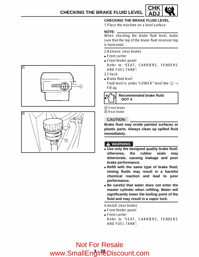
3 - 38
CHKADJ
CHECKING THE BRAKE FLUID LEVEL 1.Place the machine on a level surface.
NOTE:When checking the brake fluid level, makesure that the top of the brake fluid reservoir topis horizontal.
2.Remove: (rear brake) Front carrier Front fender panel
Refer to “SEAT, CARRIERS, FENDERSAND FUEL TANK”.
3.Check: Brake fluid level
Fluid level is under “LOWER” level line 1 →Fill up.
È Front brakeÉ Rear brake
CAUTION:Brake fluid may erode painted surfaces orplastic parts. Always clean up spilled fluidimmediately.
WARNING Use only the designed quality brake fluid:
otherwise, the rubber seals maydeteriorate, causing leakage and poorbrake performance.
Refill with the same type of brake fluid;mixing fluids may result in a harmfulchemical reaction and lead to poorperformance.
Be careful that water does not enter themaster cylinder when refilling. Water willsignificantly lower the boiling point of thefluid and may result in a vapor lock.
4.Install: (rear brake) Front fender panel Front carrier
Refer to “SEAT, CARRIERS, FENDERSAND FUEL TANK”.
Recommended brake fluid:DOT 4
È
É
CHECKING THE BRAKE FLUID LEVEL
Not For Resale www.SmallEngineDiscount.com

3 - 39
CHKADJ
CHECKING THE FRONT BRAKE PAD/CHECKING THE REAR BRAKE PAD
CHECKING THE FRONT BRAKE PAD 1.Remove: Front wheels2.Check: Brake pad
Wear indicators groove 1 almost touch thebrake disc → Replace the brake pads as aset.Refer to “FRONT AND REAR BRAKES” inCHAPTER 8.
3.Operate the brake lever.4.Install: Front wheels
Brake pad wear limit a:1 mm (0.04 in)
CHECKING THE REAR BRAKE PAD 1.Remove: Rear wheel (left)2.Check: Brake pad
Wear indicator groove 1 almostdisappeared → Replace the brake pads as aset.Refer to “FRONT AND REAR BRAKES” inCHAPTER 8.
3.Operate the brake lever or brake pedal.4.Install: Rear wheel (left)
Brake pad wear limit a:1 mm (0.04 in)
Not For Resale www.SmallEngineDiscount.com

3 - 40
CHKADJCHECKING THE BRAKE HOSE
CHECKING THE BRAKE HOSE 1.Remove: Seat Front carrier Front fender
Refer to “SEAT, CARRIERS, FENDERSAND FUEL TANK”.
Right footrest boardRefer to “FOOTREST BOARDS”.
2.Check: Front brake hoses 1 Rear brake hoses 2
Cracks/wear/damage → Replace.Fluid leakage → Replace the hose.Refer to “FRONT AND REAR BRAKES” inCHAPTER 8.
NOTE:Hold the machine in an upright position andapply the front or rear brake.
3.Check: Brake hose clamp
Loosen → Tighten.
4.Install: Right footrest board
Refer to “FOOTREST BOARDS”. Front fender Front carrier Seat
Refer to “SEAT, CARRIERS, FENDERSAND FUEL TANK”.
Not For Resale www.SmallEngineDiscount.com

3 - 41
CHKADJBLEEDING THE HYDRAULIC BRAKE SYSTEM
BLEEDING THE HYDRAULIC BRAKE SYSTEM
WARNINGBleed the brake system if: The system has been disassembled. A brake hose or brake pipe have been
loosened or removed. The brake fluid has been very low. The brake operation has been faulty.A loss of braking performance may occur ifthe brake system is not properly bled.
1.Bleed: Brake system
*****************************************************Air bleeding steps:a.Add the proper brake fluid to the reservoir.
b.Install the diaphragm. Be careful not to spillany fluid or allow the reservoir to overflow.
c.Connect the clear plastic hose 1 tightly tothe caliper bleed screw 2.
È FrontÉ Reard.Place the other end of the hose into a
container.
e.Slowly apply the brake lever or pedal severaltimes.
f. Pull the lever in or push down on the pedaland hold it.
g.Loosen the bleed screw and allow the leveror pedal to travel towards its limit.
h.Tighten the bleed screw when the lever orpedal limit has been reached, then releasethe lever or pedal.
i. Repeat steps (e) to (h) until all the airbubbles have disappeared from the fluid.
j. Tighten the bleed screw.
NOTE:If bleeding is difficult, it may be necessary tolet the brake fluid settle for a few hours.Repeat the bleeding procedure when the tinybubbles in the system have disappeared.
T R..
Bleed screw:6 Nm (0.6 m • kg, 4.3 ft • lb)
È
É
Not For Resale www.SmallEngineDiscount.com
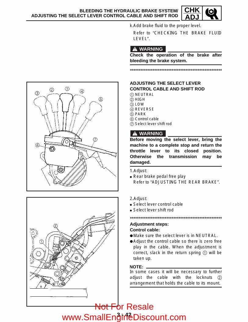
3 - 42
CHKADJ
BLEEDING THE HYDRAULIC BRAKE SYSTEM/ADJUSTING THE SELECT LEVER CONTROL CABLE AND SHIFT ROD
k.Add brake fluid to the proper level.
Refer to “CHECKING THE BRAKE FLUIDLEVEL”.
WARNINGCheck the operation of the brake afterbleeding the brake system.
*****************************************************
ADJUSTING THE SELECT LEVER CONTROL CABLE AND SHIFT ROD 1 NEUTRAL2 HIGH3 LOW4 REVERSE5 PARK6 Control cable7 Select lever shift rod
WARNINGBefore moving the select lever, bring themachine to a complete stop and return thethrottle lever to its closed position.Otherwise the transmission may bedamaged.
1.Adjust: Rear brake pedal free play
Refer to “ADJUSTING THE REAR BRAKE”.
2.Adjust: Select lever control cable Select lever shift rod
*****************************************************Adjustment steps:Control cable: Make sure the select lever is in NEUTRAL. Adjust the control cable so there is zero free
play in the cable. When the adjustment iscorrect, slack in the return spring 1 will betaken up.
NOTE:In some cases it will be necessary to furtheradjust the cable with the locknuts 2
arrangement that holds the cable to its mount.
Not For Resale www.SmallEngineDiscount.com

3 - 43
CHKADJ
ADJUSTING THE SELECT LEVER CONTROL CABLE AND SHIFT ROD/ADJUSTING THE REAR BRAKE LIGHT SWITCH
When the brake begins to work “a = 20 ~30 mm (0.8 ~ 1.2 in)”, verify that the selectlever can be shifted to REVERSE fromNEUTRAL, to PARK from REVERSE and toNEUTRAL from REVERSE.
Before the brake begins to work “a = 0 ~20 mm (0 ~ 0.8 in)”, verify that the selectlever cannot be shifted to REVERSE fromNEUTRAL, to REVERSE from PARK and toNEUTRAL from REVERSE.
Check that locknuts 2 are tightenedcorrectly.
If the operation of the select lever isincorrect, adjust the select lever control cable3 with the adjuster 4.
Select lever shift rod: Make sure the select lever is in NEUTRAL. Loosen both locknuts 1. Adjust the shift rod length for smooth and
correct shifting. Tighten the locknuts 1.
*****************************************************
ADJUSTING THE REAR BRAKE LIGHT SWITCH
NOTE:The rear brake light switch is operated bymovement of the brake pedal.The rear brake light switch is properly adjustedwhen the brake light comes on just before thebraking effect starts.
1.Check: Brake light operation timing
Incorrect → Adjust.
Not For Resale www.SmallEngineDiscount.com

3 - 44
CHKADJ
ADJUSTING THE REAR BRAKE LIGHT SWITCH/CHECKING THE FINAL GEAR OIL LEVEL
2.Adjust: Rear brake light switch operation timing
*********************************************** Hold the main body 1 of the rear brake light
switch so that it does not rotate and turn theadjusting nut 2 in direction a or b until therear brake light comes on at the proper time.
***********************************************
Direction a Brake light comes on sooner.
Direction b Brake light comes on later.
CHECKING THE FINAL GEAR OIL LEVEL 1.Place the machine on a level place.2.Remove: Oil filler bolt 1 3.Check: Oil level
Oil level should be up to the brim of the hole.Oil level low → Add oil to the proper level.
CAUTION:Take care not allow foreign material toenter the final gear case.
Recommended oil:SAE 80 API “GL-4” Hypoid gearoil
4.Install: Oil filler bolt T R.
.
23 Nm (2.3 m • kg, 17 ft • lb)
Not For Resale www.SmallEngineDiscount.com

3 - 45
CHKADJCHANGING THE FINAL GEAR OIL
CHANGING THE FINAL GEAR OIL1.Place the machine on a level surface.2.Remove: Final gear case protector 1 3.Place a receptacle under the final gear case.
4.Remove: Oil filler bolt Drain plug 1 5.Drain: Final gear oil
6.Install: Drain plug
NOTE:Check the gasket (drain plug). If it is damaged,replace it with a new one.
7.Fill: Final gear case
CAUTION:Take care not to allow foreign material toenter the final gear case.
8.Check: Oil level
Refer to “CHECKING THE FINAL GEAR OILLEVEL”.
9.Install: Oil filler bolt Final gear case protector
Periodic oil change:0.23 L (0.20 Imp qt, 0.24 US qt)
Total amount:0.25 L (0.22 Imp qt, 0.26 US qt)
Recommended oil:SAE 80 API “GL-4” Hypoid gearoil
T R..
23 Nm (2.3 m • kg, 17 ft • lb)
T R..
23 Nm (2.3 m • kg, 17 ft • lb)
T R..
16 Nm (1.6 m • kg, 11 ft • lb)
Not For Resale www.SmallEngineDiscount.com
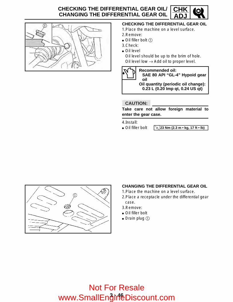
3 - 46
CHKADJ
CHECKING THE DIFFERENTIAL GEAR OIL/CHANGING THE DIFFERENTIAL GEAR OIL
CHECKING THE DIFFERENTIAL GEAR OIL1.Place the machine on a level surface.2.Remove: Oil filler bolt 1 3.Check: Oil level
Oil level should be up to the brim of hole.Oil level low → Add oil to proper level.
CAUTION:Take care not allow foreign material toenter the gear case.
4.Install: Oil filler bolt
Recommended oil:SAE 80 API “GL-4” Hypoid gearoil
Oil quantity (periodic oil change):0.23 L (0.20 Imp qt, 0.24 US qt)
T R..
23 Nm (2.3 m • kg, 17 ft • lb)
CHANGING THE DIFFERENTIAL GEAR OIL1.Place the machine on a level surface.2.Place a receptacle under the differential gear
case.3.Remove: Oil filler bolt Drain plug 1
Not For Resale www.SmallEngineDiscount.com
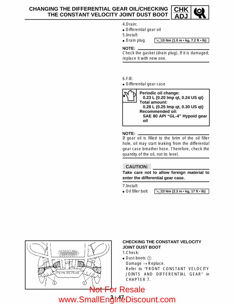
3 - 47
CHKADJ
CHANGING THE DIFFERENTIAL GEAR OIL/CHECKINGTHE CONSTANT VELOCITY JOINT DUST BOOT
4.Drain: Differential gear oil 5.Install: Drain plug
NOTE:Check the gasket (drain plug). If it is damaged,replace it with new one.
T R..
10 Nm (1.0 m • kg, 7.2 ft • lb)
6.Fill: Differential gear case
NOTE:If gear oil is filled to the brim of the oil fillerhole, oil may start leaking from the differentialgear case breather hose. Therefore, check thequantity of the oil, not its level.
CAUTION:Take care not to allow foreign material toenter the differential gear case.
7.Install: Oil filler bolt
Periodic oil change:0.23 L (0.20 Imp qt, 0.24 US qt)
Total amount:0.28 L (0.25 Imp qt, 0.30 US qt)
Recommended oil:SAE 80 API “GL-4” Hypoid gearoil
T R..
23 Nm (2.3 m • kg, 17 ft • lb)
CHECKING THE CONSTANT VELOCITY JOINT DUST BOOT 1.Check: Dust boots 1
Damage → Replace.Refer to “FRONT CONSTANT VELOCITYJOINTS AND DIFFERENTIAL GEAR” inCHAPTER 7.
Not For Resale www.SmallEngineDiscount.com

3 - 48
CHKADJ
CHECKING THE STEERING SYSTEM 1.Place the machine on a level surface.2.Check: Steering assembly bushings
Move the handlebar up and down, and/orback and forth.Excessive play → Replace the steering stembushings.
3.Check: Tie-rod ends
Turn the handlebar to the left and/or rightuntil it stops completely, then move thehandlebar from the left to the right slightly.Tie-rod end has any vertical play → Replacethe tie-rod end(s).
4.Raise the front end of the machine so thatthere is no weight on the front wheels.
5.Check: Ball joints and/or wheel bearings
Move the wheels laterally back and forth.Excessive free play → Replace the frontarms (upper and lower) and/or wheelbearings.
ADJUSTING THE TOE-IN1.Place the machine on a level surface.2.Measure: Toe-in
Out of specification → Adjust.
*****************************************************Measurement steps:
NOTE:Before measuring the toe-in, make sure thatthe tire pressure is correct.
Mark both front tire tread centers. Face the handlebar straight ahead.
Toe-in:0 ~ 10 mm (0 ~ 0.39 in)(with tire touching the ground)
CHECKING THE STEERING SYSTEM/ADJUSTING THE TOE-IN
Not For Resale www.SmallEngineDiscount.com

3 - 49
CHKADJ
Measure the width È between the marks. Rotate the front tires 180° until the marks are
exactly opposite one another. Measure the width É between the marks. Calculate the toe-in using the formula given
below.
If the toe-in is incorrect, adjust it.
*****************************************************3.Adjust: Toe-in
WARNING Be sure that both tie-rods are turned the
same amount. If not, the machine will driftright or left even though the handlebar ispositioned straight. This may lead tomishandling and an accident.
After setting the toe-in to specification,run the machine slowly for some distancewith both hands lightly holding thehandlebar and check that the handlebarresponds correctly. If not, turn either theright or left tie-rod within the toe-inspecification.
*****************************************************t
Adjustment steps: Mark both tie-rods ends.
This reference point will be needed duringadjustment.
Loosen the locknuts (tie-rod end) 1 of bothtie-rods.
The same number of turns should be givento both the right and left tie-rods 2 until thespecified toe-in is obtained. This is to keepthe length of the rods the same.
Tighten the rod end locknuts of both tie rods.
NOTE:Adjust the rod ends so that A and B are equal.
*****************************************************
Toe-in = É – È
T R..
Locknut (rod end):40 Nm (4.0 m • kg, 29 ft • lb)
ADJUSTING THE TOE-IN
Not For Resale www.SmallEngineDiscount.com

3 - 50
CHKADJ
ADJUSTING THE FRONT SHOCK ABSORBER/ADJUSTING THE REARSHOCK ABSORBER/CHECKING THE TIRE
ADJUSTING THE FRONT SHOCK ABSORBER
WARNINGAlways adjust both front shock absorberspring preload to the same setting. Unevenadjustment can cause poor handling andloss of stability.
1.Adjust: Spring preload
Turn the adjuster 1 to increase or decreasethe spring preload.
Standard position: 2Minimum (Soft) position: 1Maximum (Hard) position: 5
ADJUSTING THE REAR SHOCK ABSORBER1.Adjust: Spring preload
Turn the adjuster 1 to increase or decreasethe spring preload.
NOTE:The spring preload of the rear shock absorbercan be adjusted to suit the rider’s preference,weight, and the riding conditions.
Standard position: 2Minimum (Soft) position: 1Maximum (Hard) position: 5
CHECKING THE TIRE
WARNINGThis model is equipped with low pressuretires. It is important that they be inflatedcorrectly and maintained at the properpressures.
Not For Resale www.SmallEngineDiscount.com

3 - 51
CHKADJCHECKING THE TIRE
TIRE CHARACTERISTICS1)Tire characteristics influence the
handling of ATV’s. The tires listed belowhave been approved by Yamaha MotorCo., Ltd. for this model. If other tirecombinations are used, they canadversely affect your machine’s handlingcharacteristics and are therefore notrecommended.
TIRE PRESSURE1)Recommended tire pressure
Front 25 kPa (0.25 kg/cm2, 3.6 psi)Rear 25 kPa (0.25 kg/cm2, 3.6 psi)
2)Tire pressure below the minimumspecification could cause the tire todislodge from the rim under severe ridingconditions.The following are minimums:Front 22 kPa (0.22 kg/cm2, 3.2 psi)Rear 22 kPa (0.22 kg/cm2, 3.2 psi)
3)Use no more thanFront 250 kPa (2.5 kg/cm2, 36 psi)Rear 250 kPa (2.5 kg/cm2, 36 psi)when seating the tire beads. Higherpressures may cause the tire to burst.Inflate the tires slowly and carefully.Fast inflation could cause the tire toburst.
MAXIMUM LOADING LIMIT1)Vehicle load limit (total weight of cargo,
rider and accessories, and tongueweight): 210 kg (463 lb)
2)Front carrier: 40 kg (88 lb)3)Rear carrier: 80 kg (176 lb)4)Storage box: 2.0 kg (4.4 lb)5)Trailer hitch:Pulling load (total weight of trailer andcargo): 500 kg (1,102 lb)Tongue weight (vertical weight on trailerhitch point): 15 kg (33 lb)Be extra careful of the machine balanceand stability when towing a trailer.
Manufacturer Size Type
Front CHENG SHIN AT25 × 8-12 M911Y
Rear CHENG SHIN AT25 × 10-12 M912Y
Not For Resale www.SmallEngineDiscount.com

3 - 52
CHKADJCHECKING THE TIRE
1.Measure: Tire pressure (cold tire pressure)
Out of specification → Adjust.
NOTE: The low-pressure tire gauge 1 is included
as standard equipment. If dust or the like is stuck to this gauge, it will
not provide the correct readings. Therefore,take two measurements of the tire’s pressureand use the second reading.
WARNINGUneven or improper tire pressure mayadversely affect the handling of thismachine and may cause loss of control. Maintain proper tire pressures. Set tire pressures when the tires are cold. Tire pressures must be equal in both front
tires and equal in both rear tires.
2.Check: Tire surfaces
Wear/damage → Replace.
WARNINGIt is dangerous to ride with a worn-out tire.When tire wear is out of specification,replace the tire immediately.
Cold tire pressure Front Rear
Standard25 kPa
(0.25 kg/cm2, 3.6 psi)
25 kPa (0.25 kg/cm2,
3.6 psi)
Minimum22 kPa
(0.22 kg/cm2, 3.2 psi)
22 kPa (0.22 kg/cm2,
3.2 psi)
Maximum28 kPa
(0.28 kg/cm2, 4.0 psi)
28 kPa (0.28 kg/cm2,
4.0 psi)
Tire wear limit a:Front and rear: 3.0 mm (0.12 in)
Not For Resale www.SmallEngineDiscount.com

3 - 53
CHKADJ
CHECKING THE WHEEL/CHECKING AND LUBRICATING THE CABLE
CHECKING THE WHEEL 1.Check: Wheels 1
Damage/bends → Replace.
NOTE:Always balance the wheel when a tire or wheelhas been changed or replaced.
WARNING Never attempt even small repairs to the
wheel. Ride conservatively after installing a tire
to allow it to seat itself properly on therim.
CHECKING AND LUBRICATING THE CABLE
WARNINGA damaged cable sheath may causecorrosion and interfere with the cablemovement. An unsafe condition may resultso replace a damaged cable as soon aspossible.
1.Check: Cable sheath
Damage → Replace.2.Check: Cable operation
Unsmooth operation → Lubricate or replace.
NOTE:Hold the cable end up and apply several dropsof lubricant to the cable.
3.Apply: Lithium-soap-based grease
(onto end of the cable)
Recommended lubricant:Yamaha chain and cable lube orEngine oil
Not For Resale www.SmallEngineDiscount.com

3 - 54
CHKADJLUBRICATING THE LEVERS, PEDAL, ETC.
LUBRICATING THE LEVERS, PEDAL, ETC. 1.Lubricate the pivoting parts.
Recommended lubricant:Yamaha chain and cable lube orEngine oil
Not For Resale www.SmallEngineDiscount.com

3 - 55
CHKADJCHECKING THE BATTERY
EB305000
ELECTRICALCHECKING THE BATTERY
NOTE:Since the MF battery is a sealed type battery, itis not possible to measure the specific gravityof the electrolyte in order to check the chargestate of the battery. Therefore, the charge ofthe battery has to be checked by measuringthe voltage at the battery terminals.
CAUTION:CHARGING METHOD This is a sealed type battery. Never
remove the sealing caps. If the sealingcaps have been removed, the balance willnot be maintained and batteryperformance will deteriorate.
Charging time, charging current andcharging voltage for the MF battery aredifferent from those of general typebatteries. The MF battery should becharged as explained in “CHARGINGMETHOD”. If the battery is overcharged,the electrolyte level will dropconsiderably. Therefore, take special carewhen charging the battery.
WARNINGBattery electrolyte is dangerous; itcontains sulfuric acid which is poisonousand highly caustic.Always follow these preventive measures: Avoid bodily contact with electrolyte as it
can cause severe burns or permanent eyeinjury.
Wear protective eye gear when handlingor working near batteries.
Antidote (EXTERNAL): SKIN - Wash with water. EYES - Flush with water for 15 minutes
and get immediate medical attention.Antidote (INTERNAL): Drink large quantities of water or milk
followed with milk of magnesia, beatenegg or vegetable oil. Get immediatemedical attention.
Not For Resale www.SmallEngineDiscount.com

3 - 56
CHKADJ
Batteries generate explosive hydrogen gas.Always follow these preventive measures: Charge batteries in a well-ventilated area. Keep batteries away from fire, sparks or
open flames (e.g., welding equipment,lighted cigarettes, etc.)
DO NOT SMOKE when charging orhandling batteries.
KEEP BATTERIES AND ELECTROLYTEOUT OF REACH OF CHILDREN.
1.Remove: Seat Battery holding bracket Battery lead cover
Refer to “SEAT, CARRIERS, FENDERSAND FUEL TANK”.
2.Disconnect: Battery leads
CAUTION:First disconnect the negative lead 1, thendisconnect the positive lead 2.
3.Remove: Battery
4.Check: Battery condition
*****************************************************Battery condition checking steps: Connect a digital voltmeter to the battery
terminals.
NOTE:The charge state of an MF battery can bechecked by measuring the open-circuit voltage(i.e. the voltage when the positive terminal isdisconnected).
Tester (+) lead → battery (+) terminalTester (–) lead → battery (–) terminal
CHECKING THE BATTERY
Not For Resale www.SmallEngineDiscount.com

3 - 57
CHKADJCHECKING THE BATTERY
Check the condition of the battery using thefollowing charts.
Example: Open-circuit voltage = 12.0 V Charging time = 6.5 hours Charge condition of the battery = 20 ~ 30% Charging method for MF batteries
CAUTION: If it is impossible to set the standard
charging current, be careful not toovercharge.
When charging the battery, be sure toremove it from the motorcycle. (Ifcharging has to be done with the batterymounted on the motorcycle, be sure todisconnect the wire at the negativeterminal.)
Never remove the sealing caps of an MFbattery.
Make sure that the charging clips are infull contact with the terminal and that theyare not shorted together. (A corroded clipon the charger may cause the battery togenerate heat in the contact area. A weakclip spring may cause sparks.)
Before removing the clips from thebattery terminals, be sure to turn off thecharger’s power switch.
The open-circuit voltage variation for theMF battery, after charging, is shownbelow. As shown in the figure, the open-circuit voltage stabilizes about 30minutes after charging has beencompleted. Therefore, wait 30 minutesafter charging is completed beforemeasuring the open-circuit voltage.
Open-circuit voltage Charging time
12.8 V or higher No charging is necessary.
Not For Resale www.SmallEngineDiscount.com

3 - 58
CHKADJCHECKING THE BATTERY
Charging method using a variable voltage charger
Measure the open-circuitvoltage prior to charging.
Connect a charger andammeter to the battery andstart charging.
Is the amperage higherthan the standard chargingamperage written on thebattery?
NOYES
ChargerAmmeter
Adjust the voltage to obtain thestandard charging amperage.
Set the timer to the chargingtime determined by the open-circuit voltage.Refer to “CHECKING THEBATTERY”.
Adjust the charging voltage to20 ~ 25 V.
Monitor the amperage for 3 ~ 5 minutes. Is the standardcharging amperage exceeded?
NO
YES
If the amperage does notexceed the standard chargingamperage after 5 minutes,replace the battery.
If the required charging time exceeds 5 hours, it is advisable to check thecharging amperage after 5 hours. If there is any change in the amperage,readjust the voltage to obtain the standard charging amperage.
Leave the battery unused for more than 30 minutes before measuring itsopen-circuit voltage.12.8 V → Charging is complete.12.0 ~ 12.7 V → Recharging is required.Under 12.0 V → Replace the battery.
Leave the battery unused formore than 30 minutes beforemeasuring its open-circuit voltage.
Set the charging voltage to16 ~ 17 V. (If the chargingvoltage is lower, charging willbe insufficient, if it is higher,the battery will be over-charged.)
NOTE:
NOTE:
Not For Resale www.SmallEngineDiscount.com

3 - 59
CHKADJCHECKING THE BATTERY
Charging method using a constant voltage charger
Measure the open-circuitvoltage prior to charging.
Connect a charger andammeter to the battery andstart charging.
NOYESIs the amperage higherthan the standard chargingamperage written on thebattery?
Charge the battery until the chargingvoltage reaches 15 V.
Leave the battery unused for more than 30minutes before measuring its open-circuitvoltage.12.8 V → Charging is complete.12.0 ~ 12.7 V → Recharging is required.Under 12.0 V → Replace the battery.
This type of battery charger cannotcharge an MF battery. A variablevoltage charger is recommended.
Leave the battery unused formore than 30 minutes beforemeasuring its open-circuit voltage.
NOTE:
Set the charging time to amaximum of 20 hours.
NOTE:
Constant amperage chargers arenot suitable for charging MFbatteries.
CAUTION:
Charger
AmmeterVoltmeter
Not For Resale www.SmallEngineDiscount.com

3 - 60
CHKADJ
CHECKING THE BATTERY/CHECKING THE FUSE
5.Check: Battery terminals
Dirty → Clean with a wire brush.Poor connection → Correct.
NOTE:After cleaning the terminals, apply a light coatof grease.
6.Install: Battery7.Connect: Battery leads
CAUTION:First, connect the positive lead 1, thenconnect the negative lead 2.
8.Install: Battery lead cover Battery holding bracket Seat
Refer to “SEAT, CARRIERS, FENDERSAND FUEL TANK”.
CHECKING THE FUSE
CAUTION:Always turn off the main switch whenchecking or replacing a fuse. Otherwise, ashort circuit may occur.
1.Remove: Seat
Refer to “SEAT, CARRIERS, FENDERSAND FUEL TANK”.
2.Check: Fuses
*****************************************************Checking steps: Connect the pocket tester to the fuse and
check it for continuity.
Not For Resale www.SmallEngineDiscount.com

3 - 61
CHKADJCHECKING THE FUSE
NOTE:Set the tester to the “Ω × 1” position.
If the tester indicates ∞, replace the fuse.
*****************************************************3.Replace: Blown fuse
*****************************************************Replacement steps: Turn off the ignition. Install a new fuse of the proper amperage. Turn on switches to verify operation of the
related electrical devices. If the fuse immediately blows again, check
the electrical circuit.
*****************************************************
WARNINGNever use a fuse with a rating other thanthat specified. Never use other materials inplace of a fuse. An improper fuse may causeextensive damage to the electrical system, amalfunction of the lighting and ignitionsystems and could possibly cause a fire.
Pocket tester:P/N. YU-03112, 90890-03112
Description Current rating Quantity
Main 30 A 1
Headlight 15 A 1
Ignition 10 A 1
Terminal (Auxiliary DC jack)
10 A 1
4WD (Four-wheel drive) 3 A 1
Signaling system fuse 10 A 1
Backup fuse (odometer)
10 A 1
Reserve 30 A 1
Reserve 15 A 1
Reserve 10 A 1
Reserve 3 A 1
Not For Resale www.SmallEngineDiscount.com

3 - 62
CHKADJ
CHECKING THE FUSE/ADJUSTING THE HEADLIGHTBEAM/CHANGING THE HEADLIGHT BULB
4.Install: Seat
Refer to “SEAT, CARRIERS, FENDERSAND FUEL TANK”.
ADJUSTING THE HEADLIGHT BEAM 1.Adjust: Headlight beam (vertically)
Turn the adjuster 1 in or out.
Turning in Headlight beam raised.
Turning out Headlight beam lowered.
CHANGING THE HEADLIGHT BULB 1.Remove: Cover 1
2.Remove: Bulb holder 1 Bulb
NOTE:Turn the bulb holder counterclockwise andremove the defective bulb.
WARNINGKeep flammable products and your handsaway from the bulb while it is on, since itwill be hot. Do not touch the bulb until itcools down.
Not For Resale www.SmallEngineDiscount.com

3 - 63
CHKADJCHANGING THE HEADLIGHT BULB
3.Install: Bulb
Secure the new bulb with the headlight unit.
CAUTION:Avoid touching the glass part of the bulb.Keep it free from oil; otherwise, thetransparency of the glass, life of the bulb,and luminous flux will be adverselyaffected. If oil gets on the bulb, thoroughlyclean it with a cloth moistened with alcoholor lacquer thinner.
4.Install: Bulb holder Cover
New
Not For Resale www.SmallEngineDiscount.com

4 - 1
ENGENGINE REMOVAL
ENGINEENGINE REMOVALAIR DUCTS, MUFFLER AND EXHAUST PIPE
Order Job name/Part name Q’ty Remarks
Removing the air ducts, muffler and exhaust pipe
Remove the parts in the order below.
Engine oil Drain.Refer to “CHANGING THE ENGINE OIL”in CHAPTER 3.
Front and rear fender/footrest boards Refer to “SEAT, CARRIERS, FENDERSAND FUEL TANK” in CHAPTER 3.Fuel tank/rubber cover
Coolant Drain.Refer to “CHANGING THE COOLANT” in CHAPTER 3.
Carburetor assembly Refer to “CARBURETOR” in CHAPTER 6.1 Air duct assembly 1 12 Muffler 13 Exhaust pipe stay 1 14 Exhaust pipe/gasket 1/15 Air duct assembly 2 1
Not For Resale www.SmallEngineDiscount.com

4 - 2
ENGENGINE REMOVAL
Order Job name/Part name Q’ty Remarks
6 Final drive gear case breather hose 17 Cylinder head breather hose 18 Vacuum chamber breather hose 19 Air filter case 1
For installation, reverse the removal procedure.
4
Not For Resale www.SmallEngineDiscount.com

4 - 3
ENGENGINE REMOVAL
SELECT LEVER UNIT AND COOLANT RESERVOIR
Order Job name/Part name Q’ty Remarks
Removing the select lever unit and coolant reservoir
Remove the parts in the order below.
1 Shift arm 12 Select lever shift rod 13 Select lever unit 14 Coolant reservoir breather hose 15 Coolant reservoir hose 16 Coolant reservoir 1
For installation, reverse the removal procedure.
Not For Resale www.SmallEngineDiscount.com

4 - 4
ENGENGINE REMOVAL
HOSES AND LEADS
Order Job name/Part name Q’ty Remarks
Removing the hoses and leads Remove the parts in the order below.Water pump inlet hose Refer to “WATER PUMP” in CHAPTER 5.
1 Cylinder head breather hose 12 Spark plug lead 13 Thermo switch 1 lead 14 Starter motor lead 15 A.C. magneto lead coupler 26 Speed sensor lead coupler 17 Reverse switch lead 1 Green/White8 Neutral switch lead 1 Sky blue9 High-range switch 1 Blue/White
10 Low-range switch 1 White/Red11 Engine ground lead 1
For installation, reverse the removal procedure.
Not For Resale www.SmallEngineDiscount.com

4 - 5
ENGENGINE REMOVAL
ENGINE MOUNTING BOLTS
Order Job name/Part name Q’ty Remarks
Removing the engine mounting bolts Remove the parts in the order below.Rear wheels Refer to “FRONT AND REAR WHEELS”
in CHAPTER 8.Swingarm Refer to “REAR SHOCK ABSORBER
AND SWINGARM” in CHAPTER 8.1 Engine mounting bolt (rear-lower)/nut 1/12 Engine mounting bolt (rear-upper)/nut 1/13 Engine bracket bolt (front-lower) 44 Engine mounting bolt (font-lower) 25 Engine bracket (front-lower) 26 Engine bracket bolt (front-upper) 27 Engine mounting bolt (front-upper)/nut 1/18 Engine bracket (front-upper) 1
CAUTION:Install all of the bolts/nuts and thentighten them to full torquespecifications.
Refer to “INSTALLING THE ENGINE”.
Not For Resale www.SmallEngineDiscount.com

4 - 6
ENGENGINE REMOVAL
Order Job name/Part name Q’ty Remarks
9 Engine assembly 1 NOTE:Remove the engine assembly from theleft side of the machine.
For installation, reverse the removal procedure.
Not For Resale www.SmallEngineDiscount.com

4 - 7
ENG
INSTALLING THE ENGINE1.Install: Engine bracket (front upper) 1 Engine mount bolt (front upper)/nut 2 Engine bracket bolt (front upper) 3 Engine bracket (front lower) 4 Engine mount bolt (front lower) 5 Engine bracket bolt (front lower) 6 Engine mount bolt (rear upper)/nut 7 Engine mount bolt (rear lower)/nut 8
NOTE:Do not fully tighten the bolts and nuts.
2.Tighten: Engine mount bolt (front upper)/nut 2
Engine bracket bolt (front upper) 3
Engine mount bolt (front lower) 5
Engine bracket bolt (front lower) 6
Engine mount bolt (rear upper)/nut 7
Engine mount bolt (rear lower)/nut 8
T R..
42 Nm (4.2 m • kg, 30 ft • lb)
T R..
33 Nm (3.3 m • kg, 24 ft • lb)
T R..
42 Nm (4.2 m • kg, 30 ft • lb)
T R..
33 Nm (3.3 m • kg, 24 ft • lb)
T R..
56 Nm (5.6 m • kg, 40 ft • lb)
T R..
56 Nm (5.6 m • kg, 40 ft • lb)
ENGINE REMOVAL
Not For Resale www.SmallEngineDiscount.com

4 - 8
ENGCYLINDER HEAD
CYLINDER HEAD
Order Job name/Part name Q’ty Remarks
Removing the cylinder head Remove the parts in the order below.Fuel tank/rubber cover Refer to “SEAT, CARRIERS, FENDERS
AND FUEL TANK” in CHAPTER 3.Front fender/air filter caseAir duct assembly 1
Refer to “ENGINE REMOVAL”.Exhaust pipe/mufflerCarburetor assembly Refer to “CARBURETOR” in CHAPTER 6.Recoil starter/timing plug Refer to “ADJUSTING THE VALVE
CLEARANCE” in CHAPTER 3.Thermostat Refer to “THERMOSTAT” in CHAPTER 5.
1 Spark plug lead 12 Spark plug 13 Engine mount bolt (upper)/nut 1/14 Engine bracket (upper) 1
Not For Resale www.SmallEngineDiscount.com

4 - 9
ENGCYLINDER HEAD
Order Job name/Part name Q’ty Remarks
5 Cylinder head breather hose 16 Camshaft sprocket cover/O-ring 1/17 Tappet cover/O-ring 2/28 Thermo switch 1 lead 1 Disconnect.9 Timing chain tensioner cap bolt 1
Refer to “REMOVING/INSTALLING THECYLINDER HEAD”.
10 Timing chain tensioner/gasket 1/111 Camshaft sprocket 112 Cylinder head 113 Cylinder head gasket 114 Dowel pin 215 O-ring 1
For installation, reverse the removal procedure.
Not For Resale www.SmallEngineDiscount.com

4 - 10
ENGCYLINDER HEAD
REMOVING THE CYLINDER HEAD1.Align: “T” mark
(with stationary pointer)
*****************************************************Checking steps: Turn the crankshaft counterclockwise with a
wrench. Align the “T” mark 1 on the rotor with the
stationary pointer 2 on the crankcase cover.When the “T” mark is aligned with thestationary pointer, the piston is at the TopDead Center (T.D.C.).
NOTE: When the piston is at the Top Dead Center
(T.D.C.) on the compression stroke, thereshould be clearance between the valve stemtips and their respective rocker arm adjustingscrews.
If there is no clearance, rotate the crankshaftcounterclockwise one turn.
*****************************************************
2.Loosen: Camshaft sprocket bolt 1
NOTE:Use the rotor holding tool 2 to hold the starterpulley.
Rotor holding tool:P/N. YU-01235, 90890-01235
3.Loosen: Timing chain tensioner cap bolt4.Remove: Timing chain tensioner Camshaft sprocket
Not For Resale www.SmallEngineDiscount.com
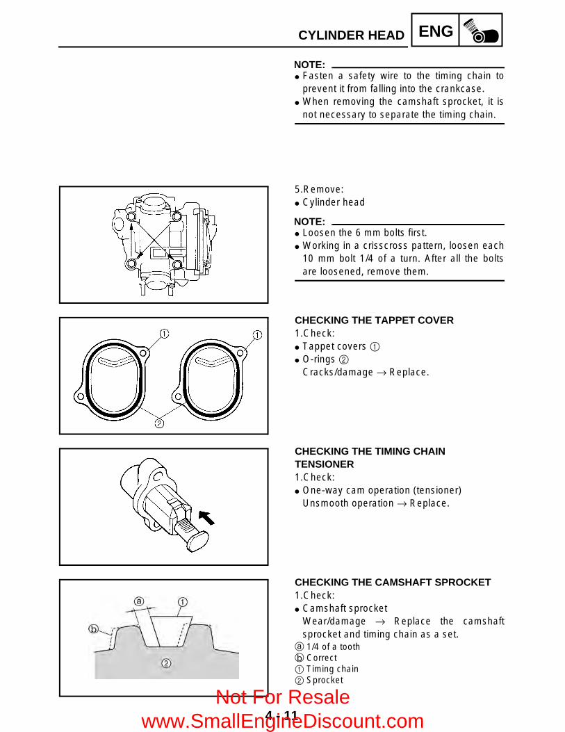
4 - 11
ENGCYLINDER HEAD
NOTE: Fasten a safety wire to the timing chain to
prevent it from falling into the crankcase. When removing the camshaft sprocket, it is
not necessary to separate the timing chain.
5.Remove: Cylinder head
NOTE: Loosen the 6 mm bolts first. Working in a crisscross pattern, loosen each
10 mm bolt 1/4 of a turn. After all the boltsare loosened, remove them.
CHECKING THE TAPPET COVER1.Check: Tappet covers 1 O-rings 2
Cracks/damage → Replace.
CHECKING THE TIMING CHAIN TENSIONER1.Check: One-way cam operation (tensioner)
Unsmooth operation → Replace.
CHECKING THE CAMSHAFT SPROCKET1.Check: Camshaft sprocket
Wear/damage → Replace the camshaftsprocket and timing chain as a set.
a 1/4 of a toothb Correct1 Timing chain2 Sprocket
Not For Resale www.SmallEngineDiscount.com
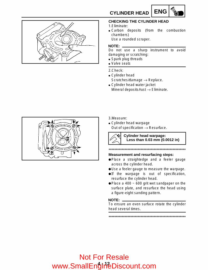
4 - 12
ENGCYLINDER HEAD
CHECKING THE CYLINDER HEAD1.Eliminate: Carbon deposits (from the combustion
chambers)Use a rounded scraper.
NOTE:Do not use a sharp instrument to avoiddamaging or scratching: Spark plug threads Valve seats
2.Check: Cylinder head
Scratches/damage → Replace. Cylinder head water jacket
Mineral deposits/rust → Eliminate.
3.Measure: Cylinder head warpage
Out of specification → Resurface.
*****************************************************Measurement and resurfacing steps: Place a straightedge and a feeler gauge
across the cylinder head. Use a feeler gauge to measure the warpage. If the warpage is out of specification,
resurface the cylinder head. Place a 400 ~ 600 grit wet sandpaper on the
surface plate, and resurface the head usinga figure-eight sanding pattern.
NOTE:To ensure an even surface rotate the cylinderhead several times.
*****************************************************
Cylinder head warpage:Less than 0.03 mm (0.0012 in)
Not For Resale www.SmallEngineDiscount.com

4 - 13
ENGCYLINDER HEAD
INSTALLING THE CYLINDER HEAD1.Install: Cylinder head Bolt (M10) Bolt (M6)
NOTE: Lubricate the washer with engine oil. Tighten the bolts (M10) in two stages and a
crisscross pattern.
T R..
40 Nm (4.0 m • kg, 29 ft • lb)
T R..
10 Nm (1.0 m • kg, 7.2 ft • lb)
2.Install: Camshaft sprocket
*****************************************************Installing steps: Rotate the camshaft to align the camshaft
pin 1 with the cylinder head match mark 2. Turn the crankshaft counterclockwise with a
wrench. Align the “T” mark 3 on the rotor with the
stationary pointer 4 on the crankcase cover.When the “T” mark is aligned with thestationary pointer, the piston is at the TopDead Center (T.D.C.).
CAUTION:Do not turn the crankshaft during thecamshaft sprocket installation.
Place the timing chain onto the camshaftsprocket.
Install the camshaft sprocket onto thecamshaft and finger tighten the sprocket bolt.
Not For Resale www.SmallEngineDiscount.com

4 - 14
ENGCYLINDER HEAD
NOTE:Be sure the “I” mark 5 on the camshaftsprocket is aligned with the match mark 2 onthe cylinder head.
Force the camshaft clockwise andcounterclockwise to remove timing chain slack.
Insert a screwdriver into the timing chaintensioner hole and push the timing chainguide inward.
While pushing the timing chain guide, besure that the camshaft sprocket “I” mark 5 isaligned with the cylinder head match mark2.
If the marks are aligned, tighten the camshaftsprocket bolt. If the marks are not aligned,change the meshing position of the camshaftsprocket and timing chain.
*****************************************************
3.Install: Timing chain tensioner
*****************************************************Installation steps: Remove the tensioner cap bolt 1, washer 2
and spring 3. Release the timing chain tensioner one-way
cam 4 and push the tensioner rod 5 all theway in.
Install the tensioner 6 with a new gasket intothe cylinder.
WARNINGAlways use a new gasket.
Install the spring, washer and cap bolt.
*****************************************************
T R..
Bolts (timing chain tensioner):11 Nm (1.1 m • kg, 8.0 ft • lb)
T R..
Cap bolt (timing chain tensioner):23 Nm (2.3 m • kg, 17 ft • lb)
Not For Resale www.SmallEngineDiscount.com

4 - 15
ENGCYLINDER HEAD
4.Tighten: Camshaft sprocket bolt 1
NOTE:Use the rotor holding tool 2 to hold the starterpulley.
5.Check: Camshaft sprocket “I” mark Rotor “T” mark
Out of alignment → Adjust.
Rotor holding tool:P/N. YU-01235, 90890-01235
T R..
60 Nm (6.0 m • kg, 43 ft • lb)
Not For Resale www.SmallEngineDiscount.com
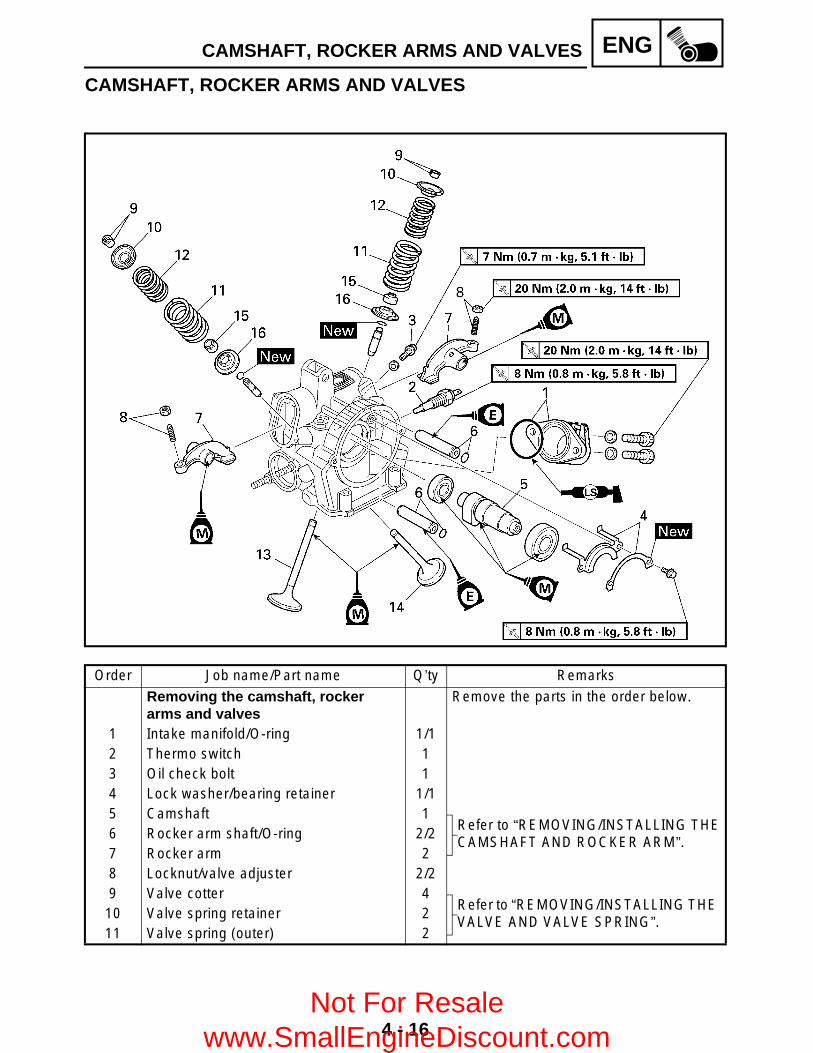
4 - 16
ENGCAMSHAFT, ROCKER ARMS AND VALVES
CAMSHAFT, ROCKER ARMS AND VALVES
Order Job name/Part name Q’ty Remarks
Removing the camshaft, rocker arms and valves
Remove the parts in the order below.
1 Intake manifold/O-ring 1/12 Thermo switch 13 Oil check bolt 14 Lock washer/bearing retainer 1/15 Camshaft 1
Refer to “REMOVING/INSTALLING THECAMSHAFT AND ROCKER ARM”.
6 Rocker arm shaft/O-ring 2/27 Rocker arm 28 Locknut/valve adjuster 2/29 Valve cotter 4
Refer to “REMOVING/INSTALLING THE VALVE AND VALVE SPRING”.
10 Valve spring retainer 211 Valve spring (outer) 2
Not For Resale www.SmallEngineDiscount.com

4 - 17
ENGCAMSHAFT, ROCKER ARMS AND VALVES
Order Job name/Part name Q’ty Remarks
12 Valve spring (inner) 2
Refer to “REMOVING/INSTALLING THEVALVE AND VALVE SPRING”.
13 Valve (intake) 114 Valve (exhaust) 115 Valve stem seal 216 Valve spring seat 2
For installation, reverse the removal procedure.
Not For Resale www.SmallEngineDiscount.com

4 - 18
ENGCAMSHAFT, ROCKER ARMS AND VALVES
REMOVING THE CAMSHAFT AND ROCKER ARM1.Remove: Camshaft 1
NOTE:Screw in a M10 bolt 2 into the thread hole onthe camshaft, and pull out the camshaft.
2.Remove: Rocker arm shafts (intake and exhaust) 1 Rocker arms 2
NOTE:Use a slide hammer 3 to remove the rockerarm shafts.
Slide hammer set:P/N. YU-01083-A
Slide hammer bolt (M6):P/N. 90890-01083
Weight:P/N. 90890-01084
REMOVING THE VALVE AND VALVE SPRING1.Check: Valve sealing
Leakage at the valve seat → Check the valveface, valve seat and valve seat width.Refer to “CHECKING THE VALVE ANDVALVE SPRING”.
*****************************************************Checking steps: Pour a clean solvent 1 into the intake and
exhaust ports. Check that the valve seals properly.
There should be no leakage at the valve seat2.
*****************************************************
Not For Resale www.SmallEngineDiscount.com

4 - 19
ENGCAMSHAFT, ROCKER ARMS AND VALVES
2.Remove: Valve cotters
NOTE:Attach a valve spring compressor 1 betweenthe valve spring retainer and the cylinder headto remove the valve cotters.
CHECKING THE CAMSHAFT 1.Check: Cam lobes
Pitting/scratches/blue discoloration → Replace.
2.Measure: Cam lobes length a and b.
Out of specification → Replace.
Valve spring compressor:P/N. YM-04019, 90890-04019
Camshaft lobe limit:Intake:a 40.52 mm (1.595 in)b 32.08 mm (1.263 in)
Exhaust:a 40.52 mm (1.595 in)b 32.08 mm (1.263 in)
CHECKING THE ROCKER ARM AND CAMSHAFT1.Check: Camshaft lobe contact surface 1 Valve adjusters 2
Blue discoloration/pitting/scratches → Replace.
Not For Resale www.SmallEngineDiscount.com

4 - 20
ENGCAMSHAFT, ROCKER ARMS AND VALVES
2.Check: Rocker arms Rocker arm shafts
Damage/wear → Replace.
*****************************************************Checking steps: Check the two contact areas on the rocker
arms for signs of abnormal wear.1) Rocker arm shaft hole2) Camshaft lobe contact surface
Excessive wear → Replace. Check the surface of the rocker arm shafts.
Blue discoloration/pitting/scratches → Replace/check lubrication.
Measure the inside diameter a of the rockerarm holes.Out of specification → Replace.
Measure the outside diameter b of therocker arm shafts.Out of specification → Replace.
Calculate the clearance by subtracting therocker arm shaft outside diameter from therocker arm inside diameter.Clearance greater than 0.08 mm (0.003 in)→ Replace the defective part(s).
*****************************************************
Rocker arm inside diameter:12.000 ~ 12.018 mm (0.4724 ~ 0.4731 in)
Rocker arm outside diameter:11.981 ~ 11.991 mm(0.4717 ~ 0.4721 in)
Rocker arm to shaft standard clearance:
0.009 ~ 0.037 mm(0.0004 ~ 0.0015 in)
Not For Resale www.SmallEngineDiscount.com

4 - 21
ENGCAMSHAFT, ROCKER ARMS AND VALVES
CHECKING THE VALVE AND VALVE SPRING 1.Measure: Stem-to-guide clearance
Out of specification → Replace the valveguide.
Stem-to-guide clearance =valve guide inside diameter a –valve stem diameter b
Clearance (stem to guide):Intake:
0.010 ~ 0.037 mm(0.0004 ~ 0.0015 in)<Limit>: 0.080 mm (0.0031 in)
Exhaust:0.030 ~ 0.057 mm(0.0012 ~ 0.0022 in)<Limit>: 0.100 mm (0.0039 in)
2.Replace: Valve guide
*****************************************************Replacement steps:
NOTE:To ease guide removal, installation and tomaintain correct fit, heat the cylinder head to100 °C (212 °F) in an oven.
Remove the valve guide using a valve guideremover 1.
Install the new valve guide using a valveguide remover 1 and valve guide installer2.
After installing the valve guide, bore thevalve guide using a valve guide reamer 3 toobtain proper stem-to-guide clearance.
NOTE:After replacing the valve guide reface the valveseat.
*****************************************************
Valve guide remover (7.0 mm):P/N. YM-01225-A, 90890-01225
Valve guide installer (7.0 mm):P/N. YM-04017, 90890-04017
Valve guide reamer (7.0 mm):P/N. YM-01227, 90890-01227
Not For Resale www.SmallEngineDiscount.com

4 - 22
ENGCAMSHAFT, ROCKER ARMS AND VALVES
3.Check: Valve face
Pitting/wear → Grind the face. Valve stem end
Mushroom shape or diameter larger than thebody of the stem → Replace.
4.Measure: Margin thickness a
Out of specification → Replace.
Margin thickness:Intake:
1.0 ~ 1.4 mm (0.0394 ~ 0.0551 in)Exhaust:
0.8 ~ 1.2 mm (0.0315 ~ 0.0472 in)
5.Measure: Runout (valve stem)
Out of specification → Replace.
NOTE: When installing a new valve always replace
the guide. If the valve is removed or replaced always
replace the oil seal.
6.Eliminate: Carbon deposits
(from the valve face and valve seat)7.Check: Valve seats
Pitting/wear → Reface the valve seat.8.Measure: Valve seat width a
Out of specification → Reface the valve seat.
Runout limit:0.01 mm (0.0004 in)
Valve seat width:Intake:
1.2 ~ 1.4 mm (0.0472 ~ 0.0551 in)<Limit>: 1.6 mm (0.0630 in)
Exhaust:1.2 ~ 1.4 mm (0.0472 ~ 0.0551 in)<Limit>: 1.6 mm (0.0630 in)
Not For Resale www.SmallEngineDiscount.com

4 - 23
ENGCAMSHAFT, ROCKER ARMS AND VALVES
*****************************************************Measurement steps: Apply Mechanic’s blueing dye (Dykem) b to
the valve face. Install the valve into the cylinder head. Press the valve through the valve guide and
onto the valve seat to make a clear pattern. Measure the valve seat width. Where the
valve seat and valve face made contact,blueing will have been removed.
If the valve seat is too wide, too narrow, orthe seat is not centered, the valve seat mustbe refaced.
*****************************************************
9.Lap: Valve face Valve seat
NOTE:After refacing the valve seat or replacing thevalve and valve guide, the valve seat andvalve face should be lapped.
*****************************************************Lapping steps: Apply a coarse lapping compound to the
valve face.
CAUTION:Do not let the compound enter the gapbetween the valve stem and the guide.
Apply molybdenum disulfide oil to the valvestem.
Install the valve into the cylinder head. Turn the valve until the valve face and valve
seat are evenly polished, then clean off all ofthe compound.
NOTE:For best lapping results, lightly tap the valveseat while rotating the valve back and forthbetween your hands.
Not For Resale www.SmallEngineDiscount.com

4 - 24
ENGCAMSHAFT, ROCKER ARMS AND VALVES
Apply a fine lapping compound to the valveface and repeat the above steps.
NOTE:After every lapping operation be sure to cleanoff all of the compound from the valve face andvalve seat.
Apply Mechanic’s blueing dye (Dykem) to thevalve face.
Install the valve into the cylinder head. Press the valve through the valve guide and
onto the valve seat to make a clear pattern. Measure the valve seat width again. If the
valve seat width is out of specification, refaceand relap the valve seat.
*****************************************************
10.Measure: Valve spring free length a
Out of specification → Replace.
11.Measure: Compressed spring force a
Out of specification → Replace.b Installed length
Free length (valve spring):Inner:
39.9 mm (1.57 in)<Limit>: 37.9 mm (1.49 in)
Outer:43.27 mm (1.70 in)<Limit>: 41.27 mm (1.62 in)
Compressed spring force:Inner:
104.9 ~ 120.6 N at 33.6 mm(10.70 ~ 12.30 kg, 23.58 ~ 27.11 lb at 1.32 in)
Outer:235.4 ~ 251.1 N at 36.6 mm(24.00 ~ 25.60 kg, 52.91 ~ 56.45 lb at 1.44 in)
Not For Resale www.SmallEngineDiscount.com
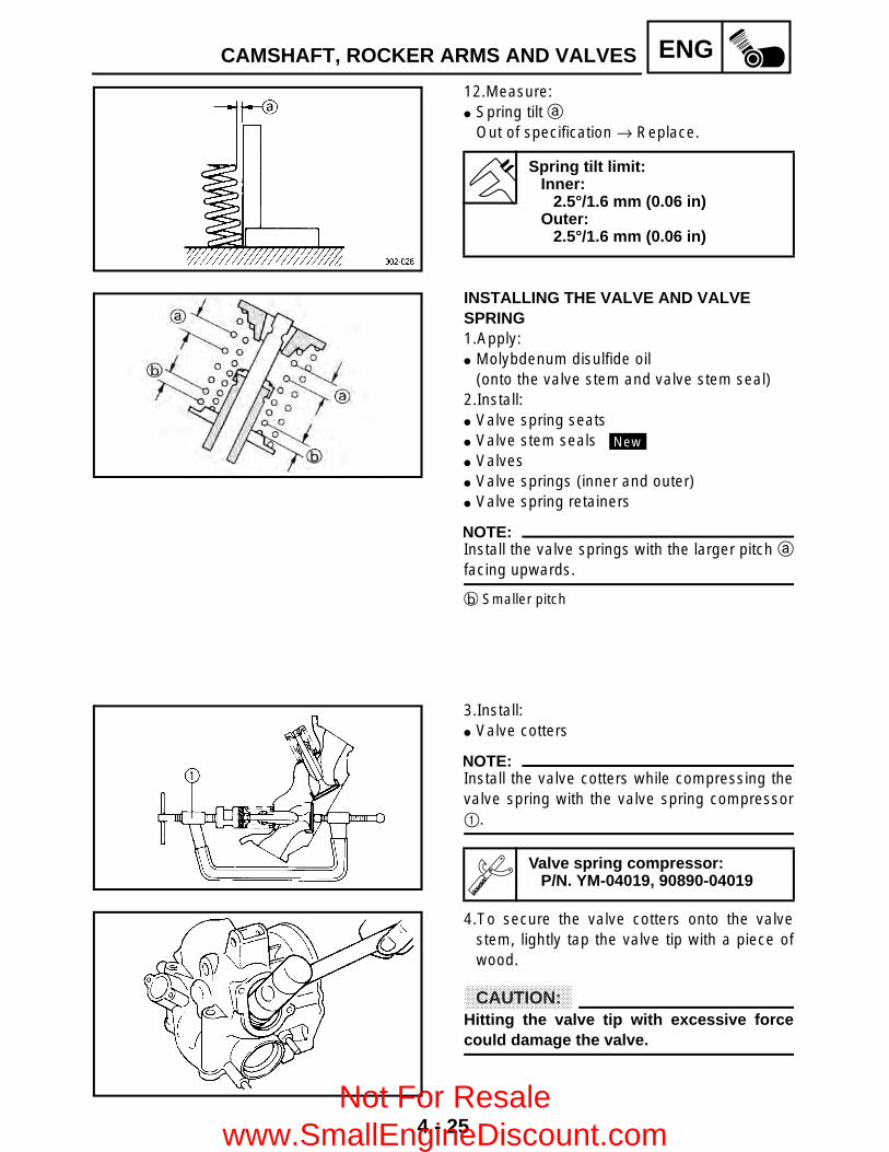
4 - 25
ENGCAMSHAFT, ROCKER ARMS AND VALVES
12.Measure: Spring tilt a
Out of specification → Replace.
Spring tilt limit:Inner:
2.5°/1.6 mm (0.06 in)Outer:
2.5°/1.6 mm (0.06 in)
INSTALLING THE VALVE AND VALVE SPRING 1.Apply: Molybdenum disulfide oil
(onto the valve stem and valve stem seal)2.Install: Valve spring seats Valve stem seals Valves Valve springs (inner and outer) Valve spring retainers
NOTE:Install the valve springs with the larger pitch afacing upwards.
b Smaller pitch
New
3.Install: Valve cotters
NOTE:Install the valve cotters while compressing thevalve spring with the valve spring compressor1.
4.To secure the valve cotters onto the valvestem, lightly tap the valve tip with a piece ofwood.
CAUTION:Hitting the valve tip with excessive forcecould damage the valve.
Valve spring compressor:P/N. YM-04019, 90890-04019
Not For Resale www.SmallEngineDiscount.com
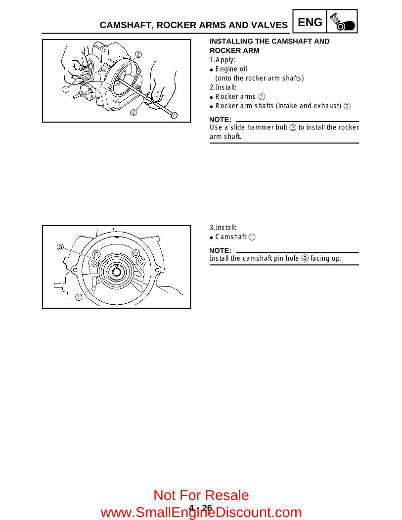
4 - 26
ENGCAMSHAFT, ROCKER ARMS AND VALVES
INSTALLING THE CAMSHAFT AND ROCKER ARM 1.Apply: Engine oil
(onto the rocker arm shafts)2.Install: Rocker arms 1 Rocker arm shafts (intake and exhaust) 2
NOTE:Use a slide hammer bolt 3 to install the rockerarm shaft.
3.Install: Camshaft 1
NOTE:Install the camshaft pin hole a facing up.
Not For Resale www.SmallEngineDiscount.com

4 - 27
ENGCYLINDER AND PISTON
CYLINDER AND PISTON
Order Job name/Part name Q’ty Remarks
Removing the cylinder and piston Remove the parts in the order below.Cylinder head Refer to “CYLINDER HEAD”.Water pump outlet hose/pipe Refer to “WATER PUMP” in CHAPTER 5.
1 Coolant inlet joint 12 Timing chain guide (exhaust) 13 Cylinder/O-ring 1/1 Refer to “INSTALLING THE CYLINDER”.4 Cylinder gasket 15 Dowel pin 26 O-ring 17 Piston pin clip 2
Refer to “REMOVING/INSTALLING THE PISTON”.
8 Piston pin 19 Piston 110 Piston ring set 1
For installation, reverse the removal procedure.
Not For Resale www.SmallEngineDiscount.com

4 - 28
ENGCYLINDER AND PISTON
REMOVING THE PISTON 1.Remove: Piston pin clips 1 Piston pin 2 Piston 3
NOTE:Before removing piston pin, deburr the clipgroove and pin hole area. If the piston pingroove is deburred and the piston pin is stilldifficult to remove, use the piston pin puller 4.
CAUTION:Do not use a hammer to drive the pistonpin out.
Piston pin puller:P/N. YU-01304, 90890-01304
2.Remove: Piston rings
NOTE:Spread the end gaps apart while at the sametime lifting the piston ring over the top of thepiston crown.
CHECKING THE TIMING CHAIN GUIDE 1.Check: Exhaust side timing chain guide
Wear/damage → Replace.
CHECKING THE CYLINDER AND PISTON 1.Check: Cylinder and piston walls
Vertical scratches → Rebore or replace thecylinder and the piston.
Cylinder water jacketMineral deposits/rust → Eliminate.
Not For Resale www.SmallEngineDiscount.com

4 - 29
ENGCYLINDER AND PISTON
2.Measure: Piston-to-cylinder clearance
*****************************************************Measurement steps:1st step: Measure the cylinder bore “C” with the
cylinder bore gauge.
NOTE:Measure cylinder bore “C” by taking side-to-side and front-to-back measurements of thecylinder. Then, find the average of themeasurements.
If out of specification, replace the cylinder,and the piston and piston rings as a set.
Cylinder bore “C” 84.500 ~ 84.510 mm(3.3268 ~ 3.3272 in)
Max. taper “T” 0.05 mm(0.0016 in)
Out of round “R” 0.01 mm(0.0004 in)
“C”= maximum of D1 ~ D6
“T”= maximum of D1, or D2 – maximum of D5 or D6
“R”= maximum of D1, D3 or D5 – minimum of D2, D4 or D6
2nd step: Measure piston skirt diameter “P” with a
micrometer.a 5.0 mm (0.20 in) from the piston bottom edge
If out of specification, replace the piston andpiston rings as a set.
Piston skirt diameter “P”
Standard 84.445 ~ 84.460 mm(3.3246 ~ 3.3252)
Not For Resale www.SmallEngineDiscount.com

4 - 30
ENGCYLINDER AND PISTON
3rd step: Find the piston-to-cylinder clearance with the
following formula.
If out of specification, rebore or replace thecylinder, and replace the piston and pistonrings as a set.
*****************************************************
Piston-to-cylinder clearance = Cylinder bore “C” – Piston skirt diameter “P”
Piston-to-cylinder clearance:0.040 ~ 0.065 mm(0.0016 ~ 0.0026 in)<Limit>: 0.150 mm (0.0059 in)
CHECKING THE PISTON RING 1.Measure: Ring side clearance
Use a feeler gauge. Out of specification → Replace the pistonand rings as a set.
NOTE:Clean carbon from the piston ring grooves andrings before measuring the side clearance.
2.Position: Piston ring
(in cylinder)
NOTE:Insert a ring into the cylinder and push itapproximately 40 mm (1.6 in) into the cylinder.Push the ring with the piston crown so that thering will be at a right angle to the cylinder bore.
a 40 mm (1.6 in)
Side clearance
Standard Limit
Top ring
0.03 ~ 0.07 mm(0.0012 ~ 0.0028 in)
0.12 mm(0.0047 in)
2nd ring
0.02 ~ 0.06 mm(0.0008 ~ 0.0024 in)
0.12 mm(0.0047 in)
Not For Resale www.SmallEngineDiscount.com
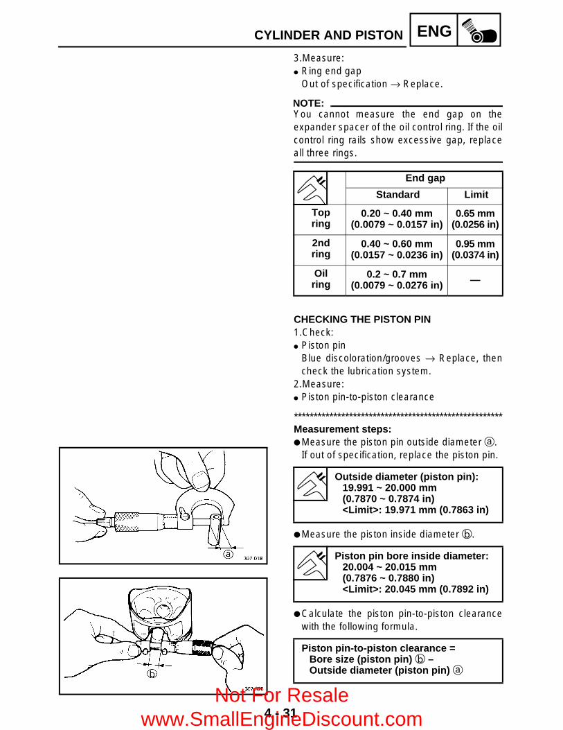
4 - 31
ENGCYLINDER AND PISTON
3.Measure: Ring end gap
Out of specification → Replace.
NOTE:You cannot measure the end gap on theexpander spacer of the oil control ring. If the oilcontrol ring rails show excessive gap, replaceall three rings.
End gap
Standard Limit
Top ring
0.20 ~ 0.40 mm(0.0079 ~ 0.0157 in)
0.65 mm(0.0256 in)
2nd ring
0.40 ~ 0.60 mm(0.0157 ~ 0.0236 in)
0.95 mm(0.0374 in)
Oilring
0.2 ~ 0.7 mm(0.0079 ~ 0.0276 in) —
CHECKING THE PISTON PIN1.Check: Piston pin
Blue discoloration/grooves → Replace, thencheck the lubrication system.
2.Measure: Piston pin-to-piston clearance
*****************************************************Measurement steps: Measure the piston pin outside diameter a.
If out of specification, replace the piston pin.
Measure the piston inside diameter b.
Calculate the piston pin-to-piston clearancewith the following formula.
Outside diameter (piston pin):19.991 ~ 20.000 mm(0.7870 ~ 0.7874 in)<Limit>: 19.971 mm (0.7863 in)
Piston pin bore inside diameter:20.004 ~ 20.015 mm(0.7876 ~ 0.7880 in)<Limit>: 20.045 mm (0.7892 in)
Piston pin-to-piston clearance =Bore size (piston pin) b –Outside diameter (piston pin) a
Not For Resale www.SmallEngineDiscount.com

4 - 32
ENGCYLINDER AND PISTON
If out of specification, replace the piston.
*****************************************************
Piston pin-to-piston clearance:0.004 ~ 0.024 mm(0.00016 ~ 0.00094 in)<Limit>: 0.074 mm (0.0029 in)
INSTALLING THE PISTON 1.Install: Piston rings
(onto the piston)
NOTE: Be sure to install the piston rings so that the
manufacturer’s marks or numbers arelocated on the upper side of the rings.
Lubricate the piston and piston rings liberallywith engine oil.
2.Position: Top ring 2nd ring Oil ring
Offset the piston ring end gaps as shown.a Top ring endb Oil ring end (upper)c Oil ring end (lower)d 2nd ring end
3.Install: Piston 1 Piston pin 2 Piston pin clips 3
NOTE: Apply engine oil onto the piston pin, piston
ring and piston. Be sure that the arrow mark a on the piston
points to the exhaust side of the engine. Before installing the piston pin clip, cover the
crankcase with a clean rag to prevent thepiston pin clip from falling into the crankcase.
New
Not For Resale www.SmallEngineDiscount.com

4 - 33
ENGCYLINDER AND PISTON
4.Lubricate: Piston Piston rings Cylinder
NOTE:Apply a liberal coating of engine oil.
INSTALLING THE CYLINDER 1.Install: Cylinder
NOTE:Install the cylinder with one hand whilecompressing the piston rings with the otherhand.
CAUTION: Be careful not to damage the timing chain
damper during installation. Pass the timing chain through the timing
chain cavity.
Not For Resale www.SmallEngineDiscount.com

4 - 34
ENGRECOIL STARTER AND A.C. MAGNETO
RECOIL STARTER AND A.C. MAGNETO
Order Job name/Part name Q’ty Remarks
Removing the CDI magneto Remove the parts in the order below.Engine oil Drain.
Refer to “CHANGING THE ENGINE OIL” in CHAPTER 3.
Seat and side panels Refer to “SEAT AND SIDE PANELS” in CHAPTER 3.
Left footrest board Refer to “FOOTREST BOARDS” in CHAPTER 3.
1 Recoil starter assembly 12 A.C. magneto coupler 2 Disconnect.3 Starter pulley 1
Refer to “REMOVING/INSTALLING THE A.C. MAGNETO”.
4 Crankcase cover (left)/gasket 1/15 Dowel pin 26 Lead holder 1
Not For Resale www.SmallEngineDiscount.com

4 - 35
ENGRECOIL STARTER AND A.C. MAGNETO
Order Job name/Part name Q’ty Remarks
7 Pickup coil 18 Stator assembly 19 Rotor 1
Refer to “REMOVING/INSTALLING THE A.C. MAGNETO”.
10 Starter wheel gear 111 Woodruff key 112 Washer 113 Starter idle gear shaft 114 Washer/bearing 1/115 Starter idle gear 1
For installation, reverse the removal procedure.
Not For Resale www.SmallEngineDiscount.com

4 - 36
ENGRECOIL STARTER AND A.C. MAGNETO
Order Job name/Part name Q’ty Remarks
Disassembling the recoil starter Remove the parts in the order below.1 Cap 1
Refer to “DISASSEMBLING/ASSEMBLING THE RECOIL STARTER”.
2 Starter handle 13 Friction plate 14 Pawl spring 15 Drive pawl 16 Spring 17 Sheave drum 18 Rope 19 Coil spring 1
For assembly, reverse the disassembly procedure.
Not For Resale www.SmallEngineDiscount.com

4 - 37
ENGRECOIL STARTER AND A.C. MAGNETO
REMOVING THE A.C. MAGNETO 1.Remove: Starter pulley 1
NOTE:Use the rotor holding tool 2 to hold the starterpulley.
2.Remove: Crankcase cover (left) Gasket Dowel pins
NOTE:Working in a crisscross pattern, loosen eachbolt 1/4 of a turn. Remove them after all ofthem are loosened.
Rotor holding tool:P/N. YU-01235, 90890-01235
3.Remove: Rotor 1
NOTE:Use the flywheel puller 2.
Flywheel puller:P/N. YM-01404, 90890-01404
DISASSEMBLING THE RECOIL STARTER 1.Remove: Cap 1 Starter handle 2
NOTE:Before untying the knot 3 above the starterhandle, make a knot 4 in the rope so that therope is not pulled into the case.
CHECKING THE CDI MAGNETO 1.Check: Stator assembly Pickup coil
Damage → Replace.
Not For Resale www.SmallEngineDiscount.com

4 - 38
ENGRECOIL STARTER AND A.C. MAGNETO
CHECKING THE STARTER CLUTCH 1.Check: Starter one-way clutch 1
Cracks/damage → Replace. Bolts 2 (starter clutch)
Loose → Replace with a new one, and clinchthe end of the bolt.
NOTE:The arrow mark on the starter clutch must faceinward, away from the rotor.
*****************************************************Checking steps: Install the starter wheel gear to the starter
clutch, and hold the starter clutch. When turning the starter wheel gear
counterclockwise È, the starter clutch andthe wheel gear should be engaged.If not, the starter clutch is faulty. Replace it.
When turning the starter wheel gearclockwise É, the starter wheel gear shouldturn freely.If not, the starter clutch is faulty. Replace it.
*****************************************************
T R..
Bolts (starter clutch):30 Nm (3.0 m • kg, 22 ft • lb)LOCTITE®
2.Check: Gear teeth (starter idle) 1 Gear teeth (starter wheel) 2
Burrs/chips/roughness/wear → Replace.
3.Check: Starter wheel gear
(contacting surface)Damage/pitting/wear → Replace.
Not For Resale www.SmallEngineDiscount.com

4 - 39
ENGRECOIL STARTER AND A.C. MAGNETO
CHECKING THE STARTER PULLEY 1.Check: Starter pulley
Cracks/pitting → Deburr or replace.
CHECKING THE RECOIL STARTER 1.Check: Rope 1 Sheave drum 2 Drive pawl 3
Wear/damage → Replace. Coil spring 4 Pawl spring 5 Spring 6
Fatigue → Replace.
ASSEMBLING THE RECOIL STARTER 1.Install: Sheave drum 1 Rope 2 Pawl spring 3 Drive pawl 4
NOTE:Wind the rope 4-1/2 turns clockwise aroundthe sheave drum. Then insert the rope into thedrum slit a.
Not For Resale www.SmallEngineDiscount.com

4 - 40
ENGRECOIL STARTER AND A.C. MAGNETO
2.Install: Starter spring 1 Sheave drum assembly 2
NOTE: Mesh the spring hook 3 with the case slit,
then wind the spring clockwise into the casefrom the larger to smaller diameter.
Mesh the sheave drum hook 4 with thespring hook 5.
3.Install: Spring 1 Friction plate 2 Nut
NOTE:Insert the spring hooks into the pawl sideholes.
4.Turn the sheave drum 3-turn clockwise togive preload to the spring.
5.Install: Starter handle 1 Cap 2
NOTE: Pass the rope through the case hole and
make a knot 3 on the rope so that the ropeis not pulled into the case.
Untie the knot 3 after making a knot 4above the handle.
INSTALLING THE A.C. MAGNETO 1.Apply: Sealant (Quick Gasket®) 1
(into the slit)
Sealant (Quick Gasket®):P/N. ACC-11001-05-01
Yamaha bond No. 1215:P/N. 90890-85505
Not For Resale www.SmallEngineDiscount.com
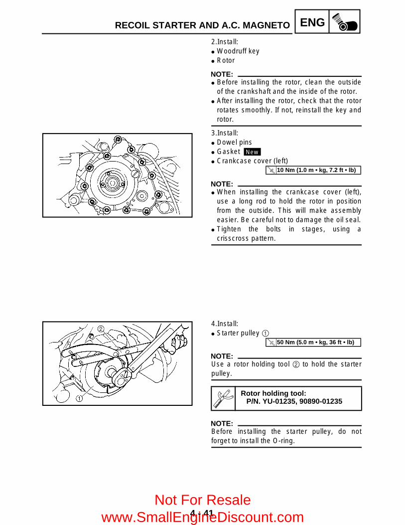
4 - 41
ENGRECOIL STARTER AND A.C. MAGNETO
2.Install: Woodruff key Rotor
NOTE: Before installing the rotor, clean the outside
of the crankshaft and the inside of the rotor. After installing the rotor, check that the rotor
rotates smoothly. If not, reinstall the key androtor.
3.Install: Dowel pins Gasket Crankcase cover (left)
NOTE: When installing the crankcase cover (left),
use a long rod to hold the rotor in positionfrom the outside. This will make assemblyeasier. Be careful not to damage the oil seal.
Tighten the bolts in stages, using acrisscross pattern.
New
T R..
10 Nm (1.0 m • kg, 7.2 ft • lb)
4.Install: Starter pulley 1
NOTE:Use a rotor holding tool 2 to hold the starterpulley.
NOTE:Before installing the starter pulley, do notforget to install the O-ring.
Rotor holding tool:P/N. YU-01235, 90890-01235
T R..
50 Nm (5.0 m • kg, 36 ft • lb)
Not For Resale www.SmallEngineDiscount.com
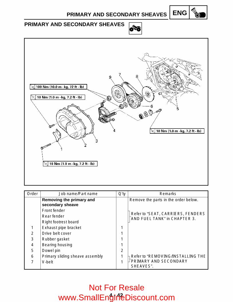
4 - 42
ENGPRIMARY AND SECONDARY SHEAVES
PRIMARY AND SECONDARY SHEAVES
Order Job name/Part name Q’ty Remarks
Removing the primary and secondary sheave
Remove the parts in the order below.
Front fenderRefer to “SEAT, CARRIERS, FENDERS AND FUEL TANK” in CHAPTER 3.
Rear fenderRight footrest board
1 Exhaust pipe bracket 12 Drive belt cover 13 Rubber gasket 14 Bearing housing 15 Dowel pin 26 Primary sliding sheave assembly 1 Refer to “REMOVING/INSTALLING THE
PRIMARY AND SECONDARY SHEAVES”.
7 V-belt 1
Not For Resale www.SmallEngineDiscount.com

4 - 43
ENGPRIMARY AND SECONDARY SHEAVES
Order Job name/Part name Q’ty Remarks
8 Primary fixed sheave 1 Refer to “REMOVING/INSTALLING THE PRIMARY AND SECONDARY SHEAVES”.
9 Secondary sheave assembly 1
For installation, reverse the removal procedure.
Not For Resale www.SmallEngineDiscount.com

4 - 44
ENGPRIMARY AND SECONDARY SHEAVES
PRIMARY SLIDING SHEAVE
Order Job name/Part name Q’ty Remarks
Disassembling the primary sliding sheave Remove the parts in the order below.
1 Primary pulley sheave cap 1
Refer to “ASSEMBLING THE PRIMARY SHEAVE”.
2 Primary pulley slider 43 Spacer 44 Primary pulley cam 15 Primary pulley weight 86 Collar 17 Oil seal 28 Primary sliding sheave 19 O-ring 1
For assembly, reverse the disassembly procedure.
Not For Resale www.SmallEngineDiscount.com

4 - 45
ENGPRIMARY AND SECONDARY SHEAVES
SECONDARY SHEAVE
Order Job name/Part name Q’ty Remarks
Disassembling the secondary sheave
Remove the parts in the order below.
1 Nut 1
Refer to “DISASSEMBLING/ASSEMBLING THE SECONDARY SHEAVE”.
2 Spring seat 13 Compression spring 14 Spring seat 15 Guide pin 46 Secondary sliding sheave 17 O-ring 28 Secondary fixed sheave 19 Oil seal 10 Oil seal 1
For assembly, reverse the disassembly procedure.
Not For Resale www.SmallEngineDiscount.com

4 - 46
ENGPRIMARY AND SECONDARY SHEAVES
REMOVING THE PRIMARY AND SECONDARY SHEAVES 1.Loosen: Nut (secondary sheave) 1 Nut (primary sheave) 2
NOTE: Use the sheave holder 3 to hold the primary
sheave. First, loosen the nut (secondary sheave) 2,
then loosen the nut (primary sheave) 1.
Sheave holder:P/N. YU-01880, 90890-01701
DISASSEMBLING THE SECONDARY SHEAVE 1.Remove: Nut 1
*****************************************************Removing steps: Attach the sheave fixed block 2, locknut
wrench 3 and sheave spring compressor 4to the secondary sheave assembly.
Place the sheave fixed block in a vise andsecure it.
Tighten the sheave spring compressor nut 5and compress the spring.
Loosen the nut 1 with the locknut wrench3.
Remove the nut 1. Remove the sheave spring compressor and
locknut wrench.
*****************************************************
Sheave fixed block:P/N. YM-04135, 90890-04135
Locknut wrench:P/N. 90890-01348
Sheave spring compressor:P/N. YM-04134, 90890-04134
Not For Resale www.SmallEngineDiscount.com

4 - 47
ENGPRIMARY AND SECONDARY SHEAVES
CHECKING THE PRIMARY SHEAVE 1.Check: Weight outside diameter a
Out of specification → Replace the weight.
Weight outside diameter:30 mm (1.18 in)<Limit>: 29.5 mm (1.16 in)
2.Check: Primary pulley slider Primary sliding sheave splines
Wear/cracks/damage → Replace. Spacer Primary pulley cam
Cracks/damage → Replace.
3.Check: Primary sliding sheave Primary fixed sheave
Cracks/damage → Replace.
CHECKING THE SECONDARY SHEAVE 1.Check: Secondary fixed sheave smooth operation Secondary sliding sheave smooth operation
Scratches/damage → Replace as a set.2.Check: Torque cam groove 1
Wear/damage → Replace.3.Check: Guide pin 2
Wear/damage → Replace.4.Check: Secondary sheave spring
Damage → Replace.5.Measure: Secondary sheave spring free length a
Out of specification → Replace thesecondary sheave spring.
Free length:121.4 mm (4.78 in)<Limit>: 115.33 mm (4.54 in)
Not For Resale www.SmallEngineDiscount.com

4 - 48
ENGPRIMARY AND SECONDARY SHEAVES
ASSEMBLING THE PRIMARY SHEAVE 1.Clean: Primary sliding sheave face 1 Primary fixed sheave face 2 Collar 3 Weight 4 Primary pulley cam face
NOTE:Remove any excess grease.
2.Install: Weight 1
NOTE: Apply Yamaha Grizzly grease (120 g) to the
whole outer surface of the weight and install. Apply Yamaha Grizzly grease to the inner
surface of the collar. Apply Yamaha Grizzly grease to the inner
surface of the primary sliding sheave.
3.Install: Spacer Slider 1 Primary pulley cam 2 Primary sliding sheave cap
T R..
3 Nm (0.3 m • kg, 2.2 ft • lb)
ASSEMBLING THE SECONDARY SHEAVE 1.Apply: BEL-RAY assembly lube®
(to the secondary sliding sheave 1 innersurface and oil seals)
BEL-RAY assembly lube® (to the bearings, oil seals and inner surfaceof the secondary fixed sheave 2)
2.Install: Guide pin 1
Not For Resale www.SmallEngineDiscount.com
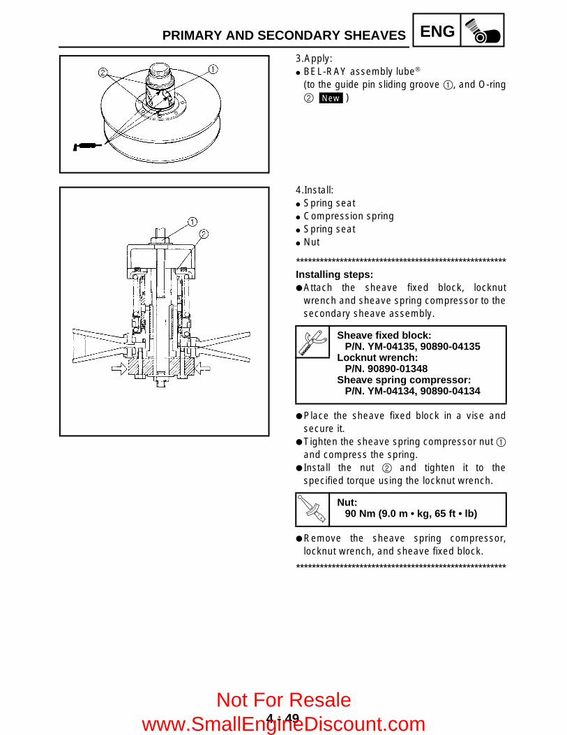
4 - 49
ENGPRIMARY AND SECONDARY SHEAVES
3.Apply: BEL-RAY assembly lube®
(to the guide pin sliding groove 1, and O-ring2 )New
4.Install: Spring seat Compression spring Spring seat Nut
*****************************************************Installing steps: Attach the sheave fixed block, locknut
wrench and sheave spring compressor to thesecondary sheave assembly.
Place the sheave fixed block in a vise andsecure it.
Tighten the sheave spring compressor nut 1and compress the spring.
Install the nut 2 and tighten it to thespecified torque using the locknut wrench.
Remove the sheave spring compressor,locknut wrench, and sheave fixed block.
*****************************************************
Sheave fixed block:P/N. YM-04135, 90890-04135
Locknut wrench:P/N. 90890-01348
Sheave spring compressor:P/N. YM-04134, 90890-04134
T R..
Nut:90 Nm (9.0 m • kg, 65 ft • lb)
Not For Resale www.SmallEngineDiscount.com

4 - 50
ENGPRIMARY AND SECONDARY SHEAVES
INSTALLING THE PRIMARY AND SECONDARY SHEAVES 1.Install: Secondary sheave assembly V-belt Primary sheave assembly
NOTE: Tightening the bolts 1 will push the
secondary sliding sheave away, causing thegap between the secondary fixed and slidingsheaves to widen.
Install the V-belt so that its arrow faces thedirection show in the illustration.
2.Tighten: Nut (primary sheave) 1
Nut (secondary sheave) 2
NOTE: Use the sheave holder 3 to hold the primary
sheave. First, tighten the nut (primary sheave) 1,
then tighten the nut (secondary sheave) 2.
Sheave holder:P/N. YU-01880, 90890-01701
T R..
100 Nm (10.0 m • kg, 72 ft • lb)
T R..
100 Nm (10.0 m • kg, 72 ft • lb)
Not For Resale www.SmallEngineDiscount.com
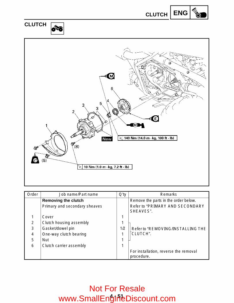
4 - 51
ENGCLUTCH
CLUTCH
Order Job name/Part name Q’ty Remarks
Removing the clutch Remove the parts in the order below.Primary and secondary sheaves Refer to “PRIMARY AND SECONDARY
SHEAVES”.1 Cover 12 Clutch housing assembly 1
Refer to “REMOVING/INSTALLING THE CLUTCH”.
3 Gasket/dowel pin 1/24 One-way clutch bearing 15 Nut 16 Clutch carrier assembly 1
For installation, reverse the removal procedure.
Not For Resale www.SmallEngineDiscount.com

4 - 52
ENGCLUTCH
Order Job name/Part name Q’ty Remarks
Disassembling the clutch housing Remove the parts in the order below.1 Oil seal 12 Circlip 13 Bearing housing 14 Circlip 15 Bearing 16 Circlip 17 Bearing 18 Clutch housing 1
For assembly, reverse the disassembly procedure.
Not For Resale www.SmallEngineDiscount.com

4 - 53
ENGCLUTCH
REMOVING THE CLUTCH 1.Remove: Clutch housing assembly Gasket Dowel pins
NOTE:Working in crisscross pattern, loosen each bolt1/4 of a turn. Remove them after all of themare loosened.
2.Straighten: Punched portion of the nut 1.3.Remove: Nut 1
NOTE:Use a clutch holding tool 2 to hold the clutchcarrier assembly.
CHECKING THE CLUTCH 1.Check: Clutch housing 1
Heat damage/wear/damage → Replace. One-way clutch bearing 2
Chafing/wear/damage → Replace.
NOTE: Replace the one-way clutch assembly and
clutch housing as a set. The one-way clutch bearing 2 must be
installed with the arrow mark side facing up.
*****************************************************Checking steps: Install the one-way clutch bearing and clutch
carrier assembly to the clutch housing andhold the clutch carrier assembly.
When turning the clutch carrier assemblyclockwise È, the clutch carrier assemblyshould turn freely.If not, the one-way clutch assembly is faulty.Replace it.
When turning the clutch carrier assemblycounterclockwise É, the clutch housing andclutch carrier assembly should be engaged.If not, the one-way clutch assembly is faulty.Replace it.
*****************************************************
Clutch holding tool:P/N. YM-91042, 90890-04086
Not For Resale www.SmallEngineDiscount.com

4 - 54
ENGCLUTCH
2.Check: Clutch shoe
Heat damage → Replace.3.Measure: Clutch shoe thickness
Out of specification → Replace.
Clutch shoe thickness:1.5 mm (0.06 in)
Clutch shoe wear limit a:1.0 mm (0.04 in)
INSTALLING THE CLUTCH 1.Install: Collar Clutch carrier assembly Nut 1
NOTE: Lubricate the nut with molybdenum disulfide
oil. Use a clutch holding tool 2 to hold the clutch
carrier assembly.
2.Lock the threads with a drift punch.
Clutch holding tool:P/N. YM-91042, 90890-04086
New T R..
140 Nm (14.0 m • kg, 100 ft • lb)
3.Install: One-way clutch bearing
NOTE:The one-way clutch bearing should beinstalled in the clutch carrier assembly with thearrow mark a facing toward the clutchhousing.
Not For Resale www.SmallEngineDiscount.com

4 - 55
ENGCLUTCH
4.Install: Dowel pins Gasket Clutch housing assembly
NOTE: Tighten the bolts in stages, using a
crisscross pattern. After tightening the bolts, check that the
clutch housing assembly to counterclockwiserotates smoothly.
New
T R..
10 Nm (1.0 m • kg, 7.2 ft • lb)
Not For Resale www.SmallEngineDiscount.com
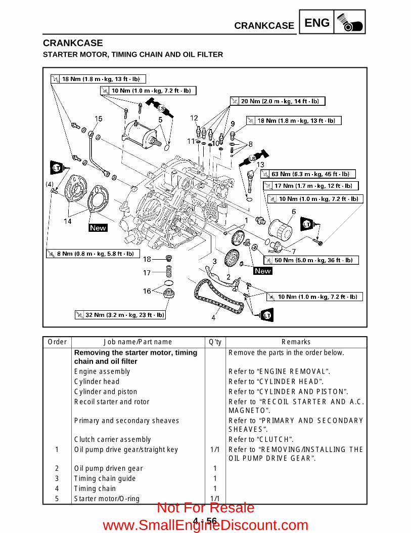
4 - 56
ENGCRANKCASE
CRANKCASESTARTER MOTOR, TIMING CHAIN AND OIL FILTER
Order Job name/Part name Q’ty Remarks
Removing the starter motor, timing chain and oil filter
Remove the parts in the order below.
Engine assembly Refer to “ENGINE REMOVAL”.Cylinder head Refer to “CYLINDER HEAD”.Cylinder and piston Refer to “CYLINDER AND PISTON”.Recoil starter and rotor Refer to “RECOIL STARTER AND A.C.
MAGNETO”.Primary and secondary sheaves Refer to “PRIMARY AND SECONDARY
SHEAVES”.Clutch carrier assembly Refer to “CLUTCH”.
1 Oil pump drive gear/straight key 1/1 Refer to “REMOVING/INSTALLING THEOIL PUMP DRIVE GEAR”.
2 Oil pump driven gear 13 Timing chain guide 14 Timing chain 15 Starter motor/O-ring 1/1
Not For Resale www.SmallEngineDiscount.com

4 - 57
ENGCRANKCASE
Order Job name/Part name Q’ty Remarks
6 Oil filter cartridge 17 Speed sensor 18 Shift cam stopper 19 Low-range switch 1
10 High-range switch 111 Neutral switch 112 Reverse switch 113 Oil filler cap 114 Bearing cover/gasket 1/115 Oil delivery pipe 116 Oil strainer cover/O-ring 1/117 Compression spring 118 Oil strainer 1
For installation, reverse the removal procedure.
Not For Resale www.SmallEngineDiscount.com

4 - 58
ENGCRANKCASE
CRANKCASE
Order Job name/Part name Q’ty Remarks
Separating the crankcase Remove the parts in the order below.1 Shift lever cover/gasket 1/1
Refer to “INSTALLING THE SHIFT LEVER”.
2 Shift lever 1/O-ring 1/13 Shift lever 2 assembly 14 Crankcase (left) 1
Refer to “SEPARATING/ASSEMBLING THE CRANKCASE”.
5 Dowel pin 26 Crankcase (right) 1
For installation, reverse the removal procedure.
Not For Resale www.SmallEngineDiscount.com
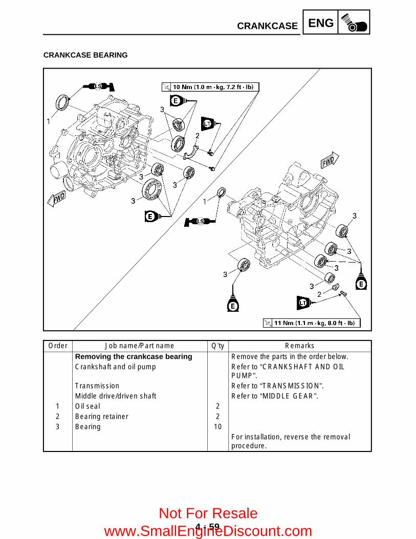
4 - 59
ENGCRANKCASE
CRANKCASE BEARING
Order Job name/Part name Q’ty Remarks
Removing the crankcase bearing Remove the parts in the order below.Crankshaft and oil pump Refer to “CRANKSHAFT AND OIL
PUMP”.Transmission Refer to “TRANSMISSION”.Middle drive/driven shaft Refer to “MIDDLE GEAR”.
1 Oil seal 22 Bearing retainer 23 Bearing 10
For installation, reverse the removal procedure.
Not For Resale www.SmallEngineDiscount.com

4 - 60
ENGCRANKCASE
REMOVING THE OIL PUMP DRIVE GEAR 1.Straighten: Lock washer tab
2.Remove: Oil pump drive gear nut
*****************************************************Removal steps: Temporary install the clutch carrier assembly1.
Hold the clutch carrier assembly with a clutchholding tool 2 and loosen the oil pump drivegear nut.
Remove the clutch carrier assembly.
*****************************************************
Clutch holding tool:P/N. YM-91042, 90890-04086
SEPARATING THE CRANKCASE 1.Separate: Left crankcase
*****************************************************Separation steps: Remove the crankcase bolts.
NOTE: Loosen each bolt 1/4 of a turn at a time and
after all the bolts are loosened, removethem.
Loosen the bolts in stages, using acrisscross pattern.
È Left crankcase É Right crankcase
È
É
Not For Resale www.SmallEngineDiscount.com

4 - 61
ENGCRANKCASE
Remove the left crankcase.
CAUTION:Use a soft hammer to tap on one side of thecrankcase. Tap only on reinforced portionsof the crankcase. Do not tap on thecrankcase mating surfaces. Work slowlyand carefully. Make sure that the crankcasehalves separate evenly.
Remove the dowel pins.
*****************************************************
CHECKING THE TIMING CHAIN AND GUIDE 1.Check: Timing chain
Cracks/stiff → Replace the timing chain andcamshaft sprocket as a set.
2.Check: Intake side timing chain guide
Wear/damage → Replace.
CHECKING THE OIL STRAINER AND OIL DELIVERY PIPE 1.Check: Oil strainer 1
2.Check: Oil delivery pipe
Cracks/damage → Replace.Clogged → Blow out with compressed air.
Not For Resale www.SmallEngineDiscount.com

4 - 62
ENGCRANKCASE
CHECKING THE CRANKCASE1.Thoroughly wash the case halves in a mild
solvent. 2.Clean all the gasket mating surfaces and
crankcase mating surfaces thoroughly.3.Check: Crankcase
Cracks/damage → Replace. Oil delivery passages
Clogged → Blow out with compressed air.CHECKING THE BEARINGS1.Check: Bearing
Clean and lubricate, then rotate the innerrace with a finger.Roughness → Replace.
ASSEMBLING THE CRANKCASE 1.Apply: Sealant (Quick Gasket®) 1
(to the mating surfaces of both case halves)
2.Install: Dowel pin 2
Sealant (Quick Gasket®):P/N. ACC-11001-05-01
Yamaha bond No. 1215:P/N. 90890-85505
3.Fit the left crankcase onto the right case. Taplightly on the case with a soft hammer.
CAUTION:Before installing and torquing thecrankcase holding bolts, be sure to checkwhether the transmission is functioningproperly by manually rotating the shift camin both directions.
Not For Resale www.SmallEngineDiscount.com

4 - 63
ENGCRANKCASE
4.Tighten: Crankcase bolts
(follow the proper tightening sequence)
È Right crankcaseÉ Left crankcase
NOTE:Tighten the bolts in stages, using a crisscrosspattern.
È
ÉT R.
.
10 Nm (1.0 m • kg, 7.2 ft • lb)
5.Apply: 4-stroke engine oil
(to the crank pin, bearing and oil deliveryhole)
6.Check: Crankshaft and transmission operation
Unsmooth operation → Repair.
INSTALLING THE SHIFT LEVER 1.Install: Shift lever 2 assembly 1
Shift lever 1 2
NOTE:When installing the shift lever 1, align thepunch mark a on the shift lever 1 with thepunch marks b on the shift lever 2.
T R..
14 Nm (1.4 m • kg, 10 ft • lb)
Not For Resale www.SmallEngineDiscount.com
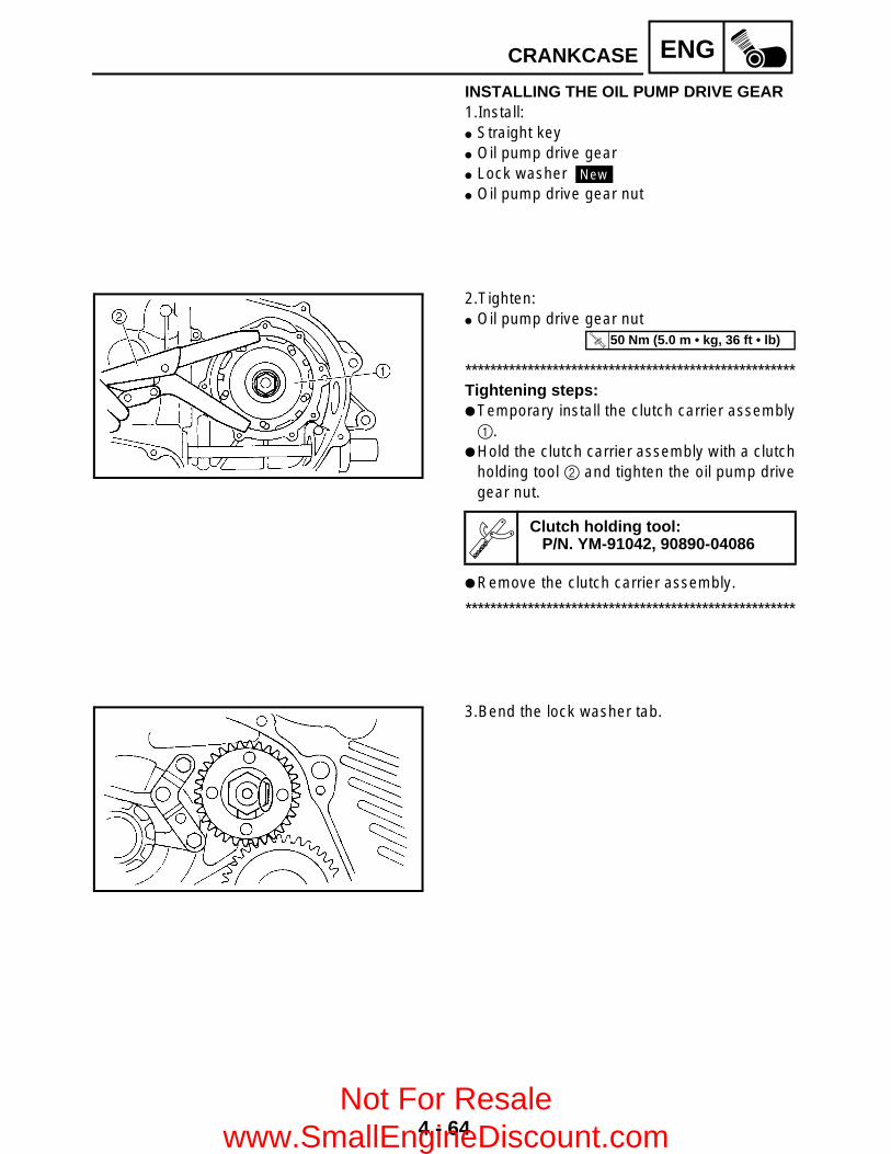
4 - 64
ENGCRANKCASE
INSTALLING THE OIL PUMP DRIVE GEAR 1.Install: Straight key Oil pump drive gear Lock washer Oil pump drive gear nut
New
2.Tighten: Oil pump drive gear nut
*****************************************************Tightening steps: Temporary install the clutch carrier assembly1.
Hold the clutch carrier assembly with a clutchholding tool 2 and tighten the oil pump drivegear nut.
Remove the clutch carrier assembly.
*****************************************************
Clutch holding tool:P/N. YM-91042, 90890-04086
T R..
50 Nm (5.0 m • kg, 36 ft • lb)
3.Bend the lock washer tab.
Not For Resale www.SmallEngineDiscount.com
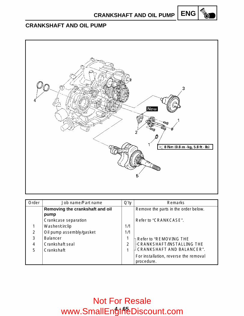
4 - 65
ENGCRANKSHAFT AND OIL PUMP
CRANKSHAFT AND OIL PUMP
Order Job name/Part name Q’ty Remarks
Removing the crankshaft and oil pump
Remove the parts in the order below.
Crankcase separation Refer to “CRANKCASE”.1 Washer/circlip 1/12 Oil pump assembly/gasket 1/13 Balancer 1 Refer to “REMOVING THE
CRANKSHAFT/INSTALLING THE CRANKSHAFT AND BALANCER”.
4 Crankshaft seal 25 Crankshaft 1
For installation, reverse the removal procedure.
Not For Resale www.SmallEngineDiscount.com
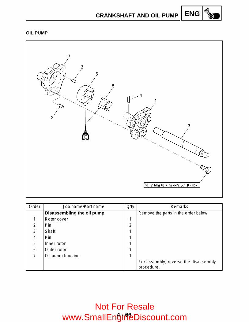
4 - 66
ENGCRANKSHAFT AND OIL PUMP
OIL PUMP
Order Job name/Part name Q’ty Remarks
Disassembling the oil pump Remove the parts in the order below.1 Rotor cover 12 Pin 23 Shaft 14 Pin 15 Inner rotor 16 Outer rotor 17 Oil pump housing 1
For assembly, reverse the disassembly procedure.
Not For Resale www.SmallEngineDiscount.com

4 - 67
ENGCRANKSHAFT AND OIL PUMP
REMOVING THE CRANKSHAFT 1.Remove: Crankshaft seal 1
NOTE:Mark a note of the position of each crankshaftseal so that they can be installed in the correctplace and in the correct direction.
2.Remove: Crankshaft
Use a crankcase separating tool 1.
Crankcase separating tool:P/N. YU-01135-A, 90890-01135
CHECKING THE OIL PUMP 1.Check: Oil pump driven gear Oil pump housing Rotor cover
Cracks/wear/damage → Replace.
2.Measure: Tip clearance a
(between the inner rotor 1 and the outerrotor 2)
Side clearance b (between the outer rotor 2 and the pumphousing 3)Out of specification → Replace the oil pump.
Tip clearance a:0.15 mm (0.006 in)<Limit>: 0.20 mm (0.008 in)
Side clearance b:0.04 ~ 0.09 mm (0.002 ~ 0.004 in)
Not For Resale www.SmallEngineDiscount.com

4 - 68
ENGCRANKSHAFT AND OIL PUMP
3.Check: Oil pump operation
Unsmooth → Repeat steps #1 and #2 orreplace the defective parts.
CHECKING THE CRANKSHAFT 1.Measure: Crank width A
Out of specification → Replace the crankshaft.
Side clearance D Out of specification → Replace the crankshaft.
Runout C Out of specification → Replace the crankshaft.
*****************************************************Crankshaft reassembling point:The crankshaft 1 and the crank pin 2 oilpassages must be properly interconnectedwith a tolerance of less than 1 mm (0.04 in).
*****************************************************
CAUTION:The buffer boss and woodruff key shouldbe replaced when removed from thecrankshaft.
Crank width:62.95 ~ 63.00 mm(2.4783 ~ 2.4803 in)
Big end side clearance:0.25 ~ 0.75 mm (0.0098 ~ 0.0295 in)<Limit>: 1.00 mm (0.0394 in)
Runout limit:C1: 0.03 mm (0.0012 in)C2: 0.03 mm (0.0012 in)
Not For Resale www.SmallEngineDiscount.com

4 - 69
ENGCRANKSHAFT AND OIL PUMP
INSTALLING THE CRANKSHAFT AND BALANCER 1.Install: Crankshaft
NOTE:Hold the connecting rod at the Top DeadCenter (T.D.C.) with one hand while turningthe nut of the installing tool with the other.Operate the installing tool until the crankshaftbottoms against the bearing.
CAUTION:Apply engine oil to each bearing to protectthe crankshaft against scratches and tomake installation easier.
Crankshaft installer set 1:P/N. YU-90050
Buffer boss installer set 2:P/N. 90890-04088
Adapter #11 3:P/N. YM-33279
Spacer (crankshaft) 4:P/N. YM-90070-A, 90890-04060
2.Install: Crankshaft seal
NOTE:Install the crankshaft seals in the correct placeand in the correct direction.
3.Install: Balancer 1
NOTE:Align the punch marks a on the drive anddriven gear.
Not For Resale www.SmallEngineDiscount.com

4 - 70
ENGTRANSMISSION
TRANSMISSION
Order Job name/Part name Q’ty Remarks
Removing the transmission Remove the parts in the order below.Crankcase separation Refer to “CRANKCASE”.
1 Driven sprocket 12 Chain 13 Clutch dog 2 14 Shift fork “L” 15 Spring 16 Low wheel gear 17 Secondary shaft 18 Middle driven gear 19 Drive axle assembly 1
10 Guide bar 1
Not For Resale www.SmallEngineDiscount.com

4 - 71
ENGTRANSMISSION
Order Job name/Part name Q’ty Remarks
11 Shift fork “R” 112 Spring 113 Shift cam 114 Stopper wheel 115 Clutch dog 1 116 High wheel gear 117 Middle drive gear 118 Stopper lever 119 Spacer/O-ring 1/1
For installation, reverse the removal procedure.
Not For Resale www.SmallEngineDiscount.com

4 - 72
ENGTRANSMISSION
CHECKING THE SHIFT FORK 1.Check: Shift fork cam follower 1 Shift fork pawl 2
Scoring/bends/wear/damage → Replace.
2.Check: Guide bar
Roll the guide bar on a flat surface.Bends → Replace.
WARNINGDo not attempt to straighten a bent guidebar.
3.Check: Shift fork movement
(on the guide bar)Unsmooth operation → Replace the shift forkand the guide bar.
4.Check: Spring
Cracks/damage → Replace.
CHECKING THE SHIFT CAM 1.Check: Shift cam grooves
Scratches/wear/damage → Replace.
Not For Resale www.SmallEngineDiscount.com
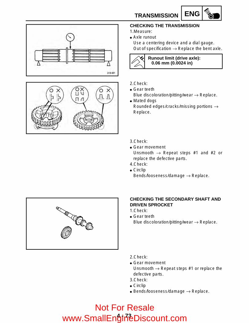
4 - 73
ENGTRANSMISSION
CHECKING THE TRANSMISSION 1.Measure: Axle runout
Use a centering device and a dial gauge.Out of specification → Replace the bent axle.
Runout limit (drive axle):0.06 mm (0.0024 in)
2.Check: Gear teeth
Blue discoloration/pitting/wear → Replace. Mated dogs
Rounded edges/cracks/missing portions → Replace.
3.Check: Gear movement
Unsmooth → Repeat steps #1 and #2 orreplace the defective parts.
4.Check: Circlip
Bends/looseness/damage → Replace.
CHECKING THE SECONDARY SHAFT AND DRIVEN SPROCKET1.Check: Gear teeth
Blue discoloration/pitting/wear → Replace.
2.Check: Gear movement
Unsmooth → Repeat steps #1 or replace thedefective parts.
3.Check: Circlip Bends/looseness/damage → Replace.
Not For Resale www.SmallEngineDiscount.com

4 - 74
ENGTRANSMISSION
CHECKING THE CHAIN1.Check: Chain
Cracks/shift → Replace the chain, secondaryshaft and driven sprocket as a set.
CHECKING THE STOPPER LEVER AND STOPPER WHEEL1.Check: Stopper lever pawl 1
Bends/damage/wear → Replace the stopperlever and stopper wheel as a set.
Stopper wheel 2 Damage/wear → Replace the stopper wheeland stopper lever as a set.
Shaft 3 Bends/damage/wear → Replace.
INSTALLING THE TRANSMISSION 1.Install: Shift cam Washer Spring (short) Shift fork “R” 1 Drive axle assembly 2 Guide bar 3 Clutch dog 2 4 Spring (long) 5 Shift fork “L” 6
NOTE:Install the shift fork with the “R” mark facingtowards the right side of the crankcase and theshift fork with the “L” mark facing towards theleft side of the crankcase. Be sure that the shiftfork guide pin is properly seated in the shiftdrum groove.
Not For Resale www.SmallEngineDiscount.com

4 - 75
ENGTRANSMISSION
2.Check: Shift operation
Unsmooth operation → Repair.
NOTE: Oil each gear and bearing thoroughly. Before assembling the crankcase, be sure
that the transmission is in neutral and thatthe gears turn freely.
Not For Resale www.SmallEngineDiscount.com

4 - 76
ENGMIDDLE GEAR
MIDDLE GEARMIDDLE DRIVE SHAFT
Order Job name/Part name Q’ty Remarks
Removing the middle drive shaft Remove the parts in the order below.Crankcase separation Refer to “CRANKCASE”.Transmission Refer to “TRANSMISSION”.
1 Bearing housing assembly 12 Nut 1 Refer to “REMOVING/INSTALLING THE
MIDDLE DRIVE SHAFT”.3 Middle drive pinion gear 14 Shim Refer to “SELECTING THE MIDDLE
DRIVE AND DRIVEN GEAR SHIM”.5 Middle drive shaft 16 Bearing retainer 2
For installation, reverse the removal procedure.
Not For Resale www.SmallEngineDiscount.com

4 - 77
ENGMIDDLE GEAR
MIDDLE DRIVEN SHAFT
Order Job name/Part name Q’ty Remarks
Removing the middle driven shaft Remove the parts in the order below.Crankcase separation Refer to “CRANKCASE”.
1 Circlip 4
Refer to “REMOVING/INSTALLING THE MIDDLE DRIVEN SHAFT”.
2 Bearing 43 Universal joint 24 Universal joint yoke 25 Bearing housing/O-ring 1/16 Shim Refer to “SELECTING THE MIDDLE
DRIVE AND DRIVEN GEAR SHIM”.7 Middle drive pinion gear 1 Refer to “REMOVING/INSTALLING THE
MIDDLE DRIVEN SHAFT”.8 Bearing retainer 19 Damper cam 1
10 Spring 111 Gear coupling 1
Not For Resale www.SmallEngineDiscount.com

4 - 78
ENGMIDDLE GEAR
Order Job name/Part name Q’ty Remarks
12 Bearing retainer 113 Middle driven shaft 1
For installation, reverse the removal procedure.
Not For Resale www.SmallEngineDiscount.com

4 - 79
ENGMIDDLE GEAR
REMOVING THE MIDDLE DRIVE SHAFT 1.Straighten: Punched portion of the nut (middle drive
pinion gear)2.Loosen: Nut (middle drive pinion gear) 1
NOTE:Secure the middle drive shaft in the vise with aclean rag.
3.Remove: Nut (middle drive pinion gear) Middle drive pinion gear Shim(s)
REMOVING THE MIDDLE DRIVEN SHAFT 1.Remove: Universal joint
*****************************************************Removal steps: Remove the circlips 1. Place the U-joint in a press. With a suitable diameter pipe 2 beneath the
yoke 3, press the bearing 4 into the pipe asshown.
NOTE:It may be necessary to lightly tap the yoke witha punch.
Repeat the steps for the opposite bearing. Remove the yoke.
NOTE:It may be necessary to lightly tap the yoke witha punch.
*****************************************************
Not For Resale www.SmallEngineDiscount.com

4 - 80
ENGMIDDLE GEAR
2.Remove: Nut 1 Washer Universal joint yoke
NOTE:Use the universal joint holder 2 to hold theuniversal joint yoke.
3.Remove: Bearing housing assembly 1
*****************************************************Removal steps: Clean the outside of the middle driven shaft. Place the middle driven shaft onto a
hydraulic press.
CAUTION: Never directly press the shaft end with a
hydraulic press, this will result in damageto the shaft thread.
Install the suitable socket 2 on the shaftend to protect the thread from damage.
Press the shaft end and remove the bearinghousing.
*****************************************************4.Remove: Bearing retainer Bearing
*****************************************************Removal steps: Attach the folded rag 1. Secure the bearing housing edge in the vise. Attach the bearing retainer wrench 2.
CAUTION:The middle driven shaft bearing retainerhas left-handed threads. To loosen theretainer turn it clockwise.
Remove the bearing retainer and bearing.
*****************************************************
Universal joint holder:P/N. YM-04062, 90890-04062
Bearing retainer wrench:P/N. YM-04128, 90890-04128
Not For Resale www.SmallEngineDiscount.com

4 - 81
ENGMIDDLE GEAR
5.Remove: Front drive shaft coupling Bearing retainer 1 Bearing
NOTE:Attach the ring nut wrench 2.
CAUTION:The middle driven shaft bearing retainerhas left-handed threads. To loosen theretainer turn it clockwise.
Ring nut wrench:P/N. YM-38404, 90890-01430
6.Remove: Middle drive shaft 1
(with bearing)
CHECKING THE PINION GEAR1.Check: Damper cam surfaces
Wear/scratches → Replace damper cam anddriven pinion gear as a set.
2.Check: Damper spring
Damage/cracks → Replace.
3.Check: Gear teeth (drive pinion gear) 1 Gear teeth (driven pinion gear) 2
Pitting/galling/wear → Replace.
Not For Resale www.SmallEngineDiscount.com
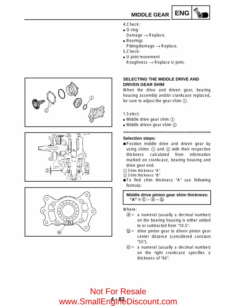
4 - 82
ENGMIDDLE GEAR
4.Check: O-ring
Damage → Replace. Bearings
Pitting/damage → Replace.5.Check: U-joint movement
Roughness → Replace U-joint.
SELECTING THE MIDDLE DRIVE AND DRIVEN GEAR SHIM When the drive and driven gear, bearinghousing assembly and/or crankcase replaced,be sure to adjust the gear shim 1.
1.Select: Middle drive gear shim 1 Middle driven gear shim 2
*****************************************************Selection steps: Position middle drive and driven gear by
using shims 1 and 2 with their respectivethickness calculated from informationmarked on crankcase, bearing housing anddrive gear end.
1 Shim thickness “A”2 Shim thickness “B” To find shim thickness “A” use following
formula:
Where:a = a numeral (usually a decimal number)
on the bearing housing is either addedto or subtracted from “10.5”.
b = drive pinion gear to driven pinion gearcenter distance (considered constant“55”).
c = a numeral (usually a decimal number)on the right crankcase specifies athickness of “66”.
Middle drive pinion gear shim thickness:“A” = c – a – b
Not For Resale www.SmallEngineDiscount.com

4 - 83
ENGMIDDLE GEAR
Example:1) If the bearing housing is marked “+04”,
..... a is 10.54.2) b is 553) If the crankcase (right) is marked “66.03”,
..... c is 66.03.4) Therefore, the shim thickness is 0.47 mm.
A = 66.03 – 10.54 – 55= 0.49
5) Round off hundredths digit and selectappropriate shim(s).In the example above, the calculated shimthickness is 0.49 mm. The chart instructsyou, however, to round off 9 to 10.
Shims are supplied in the following thickness.
Hundredths Round value
0, 1, 2 0
3, 4, 5, 6, 7 5
8, 9 10
Middle drive pinion gear shim
Thickness (mm)0.10 0.300.15 0.400.20 0.50
To find shim thickness “B” use the followingformula:
Middle driven pinion gear shimthickness:
“B” = d – e + f – g – 0.05
Not For Resale www.SmallEngineDiscount.com

4 - 84
ENGMIDDLE GEAR
Where:d = a numeral (usually a decimal number)
on the bearing housing is either addedto or subtracted from “76”.
e = a numeral (usually a decimal number)on the middle driven pinion gear iseither added to or subtracted from “59”.
f = a numeral (usually a decimal number)on the middle driven pinion gear iseither added to or subtracted from“79.5”.
g = a numeral (usually a decimal number)on the left crankcase specifies athickness of “95.8”.
Example:1) If the bearing housing is marked “+03”,
..... d is 76.03.2) If the driven pinion gear is marked “+02”,
..... e is 59.02.3) If the driven pinion gear is marked “–10”,
..... f is 79.40.4) If the crankcase (left) is marked “95.79”,
..... g is 95.79.5) Therefore, the shim thickness is 0.57 mm.
B = 76.03 – 59.02 + 79.40 – 95.79 – 0.05= 0.57
6) Round off hundredths digit and selectappropriate shim(s).In the example above, the calculated shimthickness is 0.57 mm. The chart instructsyou, however, to round off 7 to 5.
Hundredths Round value
0, 1, 2 0
3, 4, 5, 6, 7 5
8, 9 10
Not For Resale www.SmallEngineDiscount.com

4 - 85
ENGMIDDLE GEAR
Shims are supplied in the following thickness.
*****************************************************
Middle drive pinion gear shim
Thickness (mm)
0.10 0.400.15 0.500.20 0.600.30
INSTALLING THE MIDDLE DRIVEN SHAFT1.Install: Bearing retainer 1
NOTE:Attach the ring nut wrench 2.
CAUTION:The middle driven shaft bearing retainerhas left-handed threads. To tighten theretainer turn it counterclockwise.
2.Install: Bearing retainer 1
*****************************************************Installation steps: Attach the folded rag 2. Secure the bearing housing edge in the vise. Attach the bearing retainer wrench 3.
Ring nut wrench:P/N. YM-38404, 90890-01430
Bearing retainer wrench:P/N. YM-04128, 90890-04128
LT
T R..
80 Nm (8.0 m • kg, 58 ft • lb)
LT
Not For Resale www.SmallEngineDiscount.com

4 - 86
ENGMIDDLE GEAR
Tighten the bearing retainer.
CAUTION:The middle driven shaft bearing retainerhas left-handed threads. To tighten theretainer turn it counterclockwise.
*****************************************************3.Install: Shims 1 Bearing housing
NOTE:Install the shims so that the tabs are positionedas shown in the illustration.
T R..
Bearing retainer:110 Nm (11.0 m • kg, 80 ft • lb)
4.Install: Universal joint yoke (rear side) Washer Nut 1
NOTE:Use the universal joint holder 2 to hold theyoke.
Universal joint holder:P/N. YM-04062, 90890-04062
LT
T R..
97 Nm (9.7 m • kg, 70 ft • lb)
5.Install: Universal joint
*****************************************************Installation steps: Install the opposite yoke into the U-joint. Apply wheel bearing grease to the bearings.
Not For Resale www.SmallEngineDiscount.com

4 - 87
ENGMIDDLE GEAR
Install the bearing 1 onto the yoke.
CAUTION:Check each bearing. The needles caneasily fall out of their races. Slide the yokeback and forth on the bearings; the yokewill not go all the way onto a bearing if aneedle is out of place.
Press each bearing into the U-joint using asuitable socket.
NOTE:The bearing must be inserted far enough intothe U-joint so that the circlip can be installed.
Install the circlips 2 into the groove of eachbearing.
*****************************************************
INSTALLING THE MIDDLE DRIVE SHAFT 1.Tighten: Nut (middle drive pinion gear) 1
NOTE:Secure the middle drive shaft in the vise with aclean rag.
2.Lock the threads with a drift punch.
New
T R..
130 Nm (13.0 m • kg, 94 ft • lb)
MEASURING THE MIDDLE GEAR BACKLASH1.Measure: Gear lash
*****************************************************Measurement steps: Temporarily install the right crankcase. Wrap a rag 2 around a screwdriver 3, and
then insert it into the installation hole 1 ofthe left crankcase speed sensor to hold themiddle driven gear.
Middle gear lash:0.1 ~ 0.3 mm (0.004 ~ 0.012 in)
Not For Resale www.SmallEngineDiscount.com

4 - 88
ENGMIDDLE GEAR
Attach the gear lash measurement tool 3and dial gauge 4.
a 8.12 mm (0.32 in) Measure the gear lash while rotating the
middle driven shaft back and forth.
NOTE:Measure the gear lash at 4 positions. Rotatethe middle driven gear 90° each time.
If the gear lash is incorrect, adjust the gearlash by middle driven pinion gear shims and/or middle drive pinion gear shim(s).
*****************************************************
Gear lash measurement tool:P/N. YM-01467, 90890-01467
Not For Resale www.SmallEngineDiscount.com

5 - 1
COOLRADIATOR
COOLING SYSTEMRADIATOR
Order Job name/Part name Q’ty RemarksRemoving the radiator Remove the parts in the order below.Seat and fuel tank side panels Refer to “SEAT AND SIDE PANELS” in
CHAPTER 3.Front carrier, front bumper and front fender
Refer to “FRONT CARRIER, FRONT BUMPER AND FRONT FENDER” in CHAPTER 3.
Left footrest board Refer to “FOOTREST BOARDS” in CHAPTER 3.
Coolant Drain.Refer to “CHANGING THE COOLANT” in CHAPTER 3.
1 Radiator fan coupler 1 Disconnect.2 Thermo switch coupler 1 Disconnect.3 Coolant reservoir hose 1 Disconnect.4 Radiator fan breather hose 1
Not For Resale www.SmallEngineDiscount.com

5 - 2
COOLRADIATOR
Order Job name/Part name Q’ty Remarks5 Radiator inlet hose 1 Disconnect.6 Radiator outlet hose 1 Disconnect.7 Radiator 18 Radiator fan 19 Thermo switch 1
For installation, reverse the removal procedure.
5
Not For Resale www.SmallEngineDiscount.com
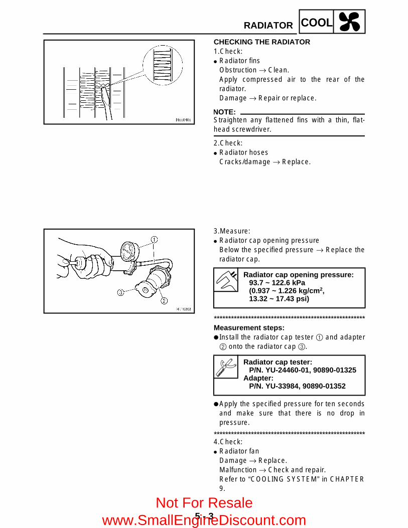
5 - 3
COOLRADIATOR
CHECKING THE RADIATOR1.Check: Radiator fins
Obstruction → Clean.Apply compressed air to the rear of theradiator.Damage → Repair or replace.
NOTE:Straighten any flattened fins with a thin, flat-head screwdriver.
2.Check: Radiator hoses
Cracks/damage → Replace.
3.Measure: Radiator cap opening pressure
Below the specified pressure → Replace theradiator cap.
*****************************************************Measurement steps: Install the radiator cap tester 1 and adapter2 onto the radiator cap 3.
Apply the specified pressure for ten secondsand make sure that there is no drop inpressure.
*****************************************************4.Check: Radiator fan
Damage → Replace.Malfunction → Check and repair.Refer to “COOLING SYSTEM” in CHAPTER9.
Radiator cap opening pressure:93.7 ~ 122.6 kPa (0.937 ~ 1.226 kg/cm2, 13.32 ~ 17.43 psi)
Radiator cap tester:P/N. YU-24460-01, 90890-01325
Adapter:P/N. YU-33984, 90890-01352
Not For Resale www.SmallEngineDiscount.com

5 - 4
COOLRADIATOR
INSTALLING THE RADIATOR1.Fill: Cooling system
(with the specified amount of therecommended coolant)Refer to “CHANGING THE COOLANT” inCHAPTER 3.
2.Check: Cooling system
Leaks → Repair or replace any faulty part.
Not For Resale www.SmallEngineDiscount.com
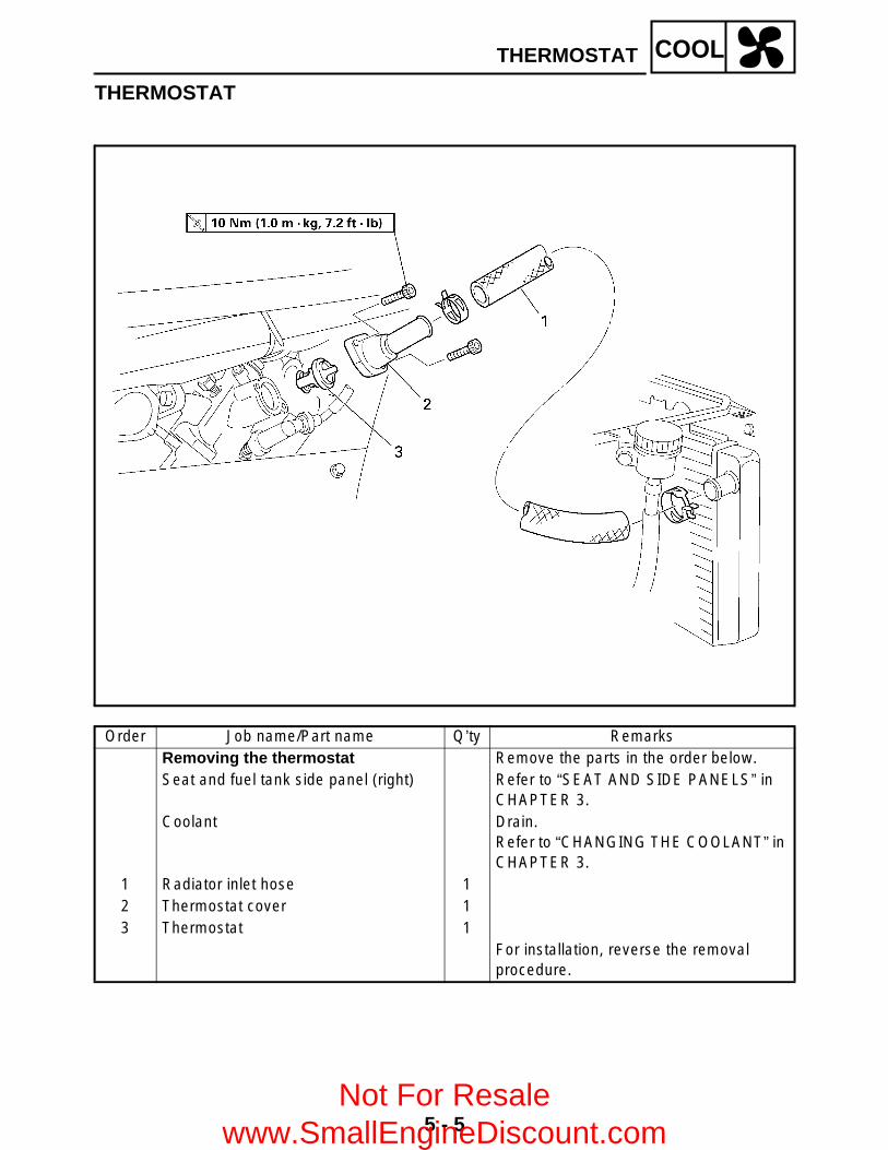
5 - 5
COOLTHERMOSTAT
THERMOSTAT
Order Job name/Part name Q’ty RemarksRemoving the thermostat Remove the parts in the order below.Seat and fuel tank side panel (right) Refer to “SEAT AND SIDE PANELS” in
CHAPTER 3.Coolant Drain.
Refer to “CHANGING THE COOLANT” in CHAPTER 3.
1 Radiator inlet hose 12 Thermostat cover 13 Thermostat 1
For installation, reverse the removal procedure.
Not For Resale www.SmallEngineDiscount.com
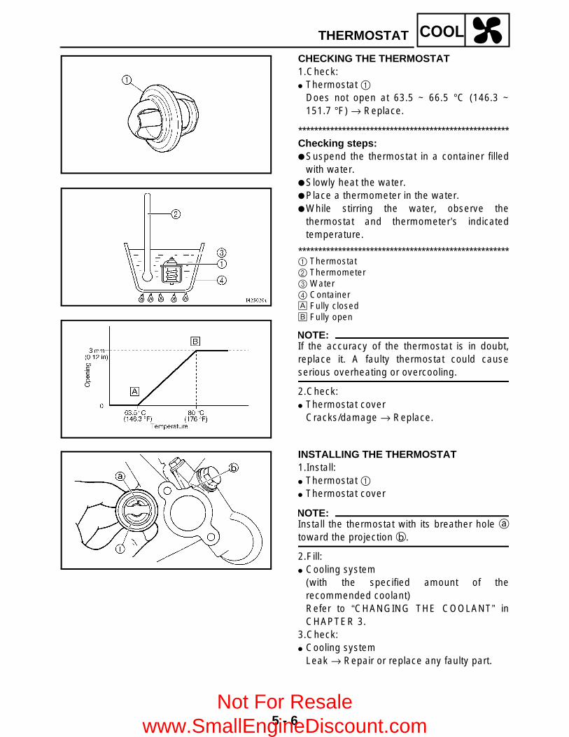
5 - 6
COOLTHERMOSTAT
CHECKING THE THERMOSTAT1.Check: Thermostat 1
Does not open at 63.5 ~ 66.5 °C (146.3 ~151.7 °F) → Replace.
*****************************************************Checking steps: Suspend the thermostat in a container filled
with water. Slowly heat the water. Place a thermometer in the water. While stirring the water, observe the
thermostat and thermometer’s indicatedtemperature.
*****************************************************1 Thermostat2 Thermometer3 Water4 ContainerÈ Fully closedÉ Fully open
NOTE:If the accuracy of the thermostat is in doubt,replace it. A faulty thermostat could causeserious overheating or overcooling.
2.Check: Thermostat cover
Cracks/damage → Replace.
INSTALLING THE THERMOSTAT1.Install: Thermostat 1 Thermostat cover
NOTE:Install the thermostat with its breather hole atoward the projection b.
2.Fill: Cooling system
(with the specified amount of therecommended coolant)Refer to “CHANGING THE COOLANT” inCHAPTER 3.
3.Check: Cooling system
Leak → Repair or replace any faulty part.
Not For Resale www.SmallEngineDiscount.com
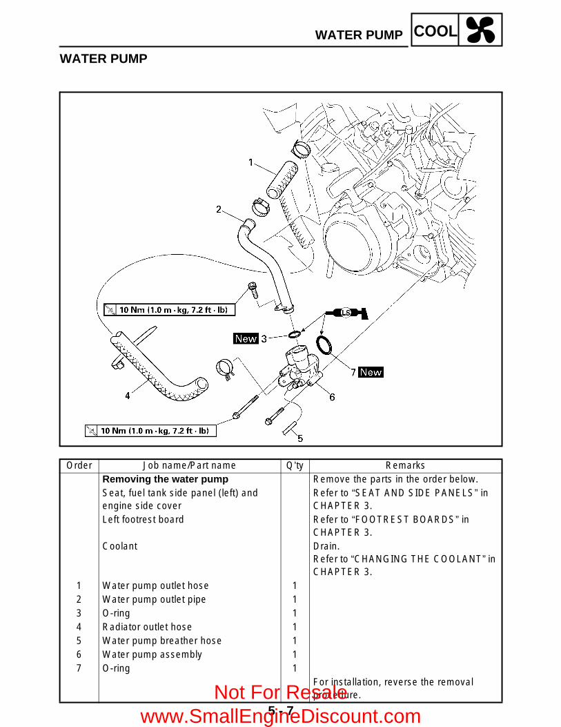
5 - 7
COOLWATER PUMP
WATER PUMP
Order Job name/Part name Q’ty RemarksRemoving the water pump Remove the parts in the order below.Seat, fuel tank side panel (left) and engine side cover
Refer to “SEAT AND SIDE PANELS” in CHAPTER 3.
Left footrest board Refer to “FOOTREST BOARDS” in CHAPTER 3.
Coolant Drain.Refer to “CHANGING THE COOLANT” in CHAPTER 3.
1 Water pump outlet hose 12 Water pump outlet pipe 13 O-ring 14 Radiator outlet hose 15 Water pump breather hose 16 Water pump assembly 17 O-ring 1
For installation, reverse the removal procedure.Not For Resale
www.SmallEngineDiscount.com

5 - 8
COOLWATER PUMP
Order Job name/Part name Q’ty RemarksDisassembling the water pump Remove the parts in the order below.
1 Water pump housing cover 12 Gasket 13 Circlip 14 Impeller 15 Rubber damper holder 16 Rubber damper 17 Water pump seal 18 Oil seal 19 Bearing 10 Water pump housing 1
For assembly, reverse the disassembly procedure.
Not For Resale www.SmallEngineDiscount.com
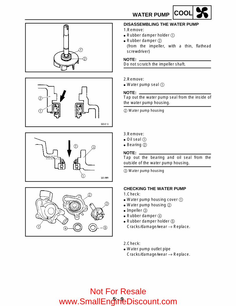
5 - 9
COOLWATER PUMP
DISASSEMBLING THE WATER PUMP1.Remove: Rubber damper holder 1 Rubber damper 2
(from the impeller, with a thin, flatheadscrewdriver)
NOTE:Do not scratch the impeller shaft.
2.Remove: Water pump seal 1
NOTE:Tap out the water pump seal from the inside ofthe water pump housing.
2 Water pump housing
3.Remove: Oil seal 1 Bearing 2
NOTE:Tap out the bearing and oil seal from theoutside of the water pump housing.
3 Water pump housing
CHECKING THE WATER PUMP1.Check: Water pump housing cover 1 Water pump housing 2 Impeller 3 Rubber damper 4 Rubber damper holder 5
Cracks/damage/wear → Replace.
2.Check: Water pump outlet pipe
Cracks/damage/wear → Replace.
Not For Resale www.SmallEngineDiscount.com

5 - 10
COOLWATER PUMP
3.Measure: Impeller shaft tilt
Out of specification → Replace.
1 Straightedge2 Impeller
Max. impeller shaft tilt:0.15 mm (0.006 in)
ASSEMBLING THE WATER PUMP1.Install: Oil seal 1
(into the water pump housing 2)
NOTE:Install the oil seal with a socket 3 thatmatches its outside diameter.
New
2.Install: Water pump seal 1
(into the water pump housing 2)
NOTE:Before installing the water pump seal 1, applytap water or coolant onto its outer surface.
CAUTION:Never lubricate the water pump sealsurface with oil or grease.
NOTE:Install the water pump seal with the specialtools.
È Push down.
Mechanical seal installer 3: P/N. YM-33221, 90890-04078
Middle driven shaft bearing driver4:
P/N. YM-04058-1, 90890-04058
New
Not For Resale www.SmallEngineDiscount.com

5 - 11
COOLWATER PUMP
3.Install: Rubber damper 1 Rubber damper holder 2
NOTE:Before installing the rubber damper, apply tapwater or coolant onto its outer surface.
CAUTION:Make sure that the rubber damper andrubber damper holder are flush with theimpeller.
New
New
Not For Resale www.SmallEngineDiscount.com

6 - 1
CARBCARBURETOR
CARBURETIONCARBURETOR
Order Job name/Part name Q’ty Remarks
Removing the carburetor Remove the parts in the order below.Seat/fuel tank side panels/fuel tank/rubber cover
Refer to “SEAT, CARRIERS, FENDERS AND FUEL TANK” in CHAPTER 3.
1 Drain hose 12 Starter cable/starter plunger 1/13 Vacuum chamber breather hose 14 Carburetor assembly 15 Throttle valve cover 16 Throttle cable end 17 Throttle cable 2 NOTE:
After removing the carburetor assembly,remove the throttle cable.
For installation, reverse the removal procedure.
6
Not For Resale www.SmallEngineDiscount.com

6 - 2
CARBCARBURETOR
Order Job name/Part name Q’ty Remarks
Disassembling the carburetor Remove the parts in the order below.1 Float chamber air vent hose 12 Throttle stop screw 13 Vacuum chamber cover 14 Spring 15 Jet needle holder 16 Spring 17 Jet needle set 18 Piston valve 19 Coasting enricher 10 Float chamber 1A Drain screw 1B Float 1 Refer to “ASSEMBLING THE
CARBURETOR”.C Needle valve set 1
Not For Resale www.SmallEngineDiscount.com

6 - 3
CARBCARBURETOR
Order Job name/Part name Q’ty Remarks
D Pilot jet 1
NOTE:Before disassembling the carburetor,make sure to note the number of timesthe pilot screw is turned out from theseated position to its set position.
E Main jet 1F Needle jet 1G Starter jet 1H Pilot air jet 1
For assembly, reverse the disassembly procedure.
Not For Resale www.SmallEngineDiscount.com

6 - 4
CARBCARBURETOR
DISASSEMBLING THE CARBURETOR
NOTE:Before disassembling the carburetor, makesure to note the number of times the pilotscrew is turned out from the seated position toits set position.
CHECKING THE CARBURETOR1.Check: Carburetor body Float chamber
Cracks/damage → Replace. Fuel passage
Contamination → Clean as indicated. Carburetor body
Contamination → Clean.
*****************************************************Cleaning steps: Wash the carburetor in a petroleum based
solvent.(Do not use any caustic carburetor cleaningsolution.)
Blow out all of the passages and jets withcompressed air.
*****************************************************
2.Check: Float 1 Float tang 2
Damage → Replace.
3.Check: Valve seat 1 Needle valve 2 O-ring 3
Contamination/wear/damage → Replace asa set.
NOTE:Always replace the needle valve and valveseat as a set.Not For Resale
www.SmallEngineDiscount.com

6 - 5
CARBCARBURETOR
4.Check: Piston valve 1
Scratches/wear/damage → Replace. Rubber diaphragm 2
Tears → Replace.
5.Check: Vacuum chamber cover 1 Spring 2
Cracks/damage → Replace.
6.Check: Diaphragm (coasting enricher) 1 Spring 2 Cover 3
Tears (diaphragm) /damage → Replace.
7.Check: Jet needle 1 Main jet 2 Needle jet 3 Pilot air jet 4 Pilot jet 5 Starter jet 6 Starter plunger 7
Bends/wear/damage → Replace. Blockage → Blow out the jets with
compressed air.
Not For Resale www.SmallEngineDiscount.com

6 - 6
CARBCARBURETOR
8.Check: Free movement (piston valve)
Sticks → Replace the piston valve guide andthe piston valve.Insert the piston valve into the carburetorbody, and check for free movement.
9.Check: Free movement (throttle valve)
Sticks → Replace.
ASSEMBLING THE CARBURETOR
CAUTION:Before reassembling, wash all of the partsin a clean petroleum based solvent.
1.Measure: Float height a
Out of specification → Adjust.
*****************************************************Measurement and adjustment steps: Hold the carburetor in an upside down
position. Measure the distance from the mating
surface of the float chamber (gasketremoved) to the top of the float.
NOTE:The float arm should be resting on the needlevalve, but not compressing it.
If the float height is not within thespecification, check the valve seat andneedle valve.
If either is worn, replace them both. If both are fine, adjust the float height by
bending the float tang 1 on the float. Recheck the float height.
*****************************************************
Float height (F.H.):13 mm (0.51 in)
Not For Resale www.SmallEngineDiscount.com
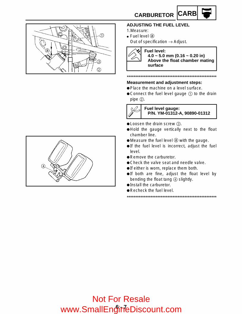
6 - 7
CARBCARBURETOR
ADJUSTING THE FUEL LEVEL1.Measure: Fuel level a
Out of specification → Adjust.
*****************************************************Measurement and adjustment steps: Place the machine on a level surface. Connect the fuel level gauge 1 to the drain
pipe 2.
Loosen the drain screw 3. Hold the gauge vertically next to the float
chamber line. Measure the fuel level a with the gauge. If the fuel level is incorrect, adjust the fuel
level. Remove the carburetor. Check the valve seat and needle valve. If either is worn, replace them both. If both are fine, adjust the float level by
bending the float tang 4 slightly. Install the carburetor. Recheck the fuel level.
*****************************************************
Fuel level:4.0 ~ 5.0 mm (0.16 ~ 0.20 in)Above the float chamber matingsurface
Fuel level gauge:P/N. YM-01312-A, 90890-01312
Not For Resale www.SmallEngineDiscount.com

7 - 1
DRIVTROUBLESHOOTING
DRIVE TRAINTROUBLESHOOTINGThe following conditions may indicate damaged shaft drive components:
NOTE:Areas A, B, and C above may be extremely difficult to diagnose. The symptoms are quite subtle anddifficult to distinguish from normal machine operating noise. If there is reason to believe thesecomponents are damaged, remove the components and check them.
Symptoms Possible Causes
1.A pronounced hesitation or “jerky” movementduring acceleration, deceleration, or sustainedspeed. (This must not be confused withengine surging or transmissioncharacteristics.)
2.A “rolling rumble” noticeable at low speed; ahigh-pitched whine; a “clunk” from a shaftdrive component or area.
3.A locked-up condition of the shaft drive trainmechanism, no power transmitted from theengine to the front and/or rear wheel.
A.Bearing damage.
B. Improper gear lash.
C.Gear tooth damage.
D.Broken drive shaft.
E.Broken gear teeth.
F. Seizure due to lack of lubrication.
G.Small foreign objects lodged between themoving parts.
1.Check: Unusual noises
*****************************************************The following “noises” may indicate amechanical defect:a.A “rolling rumble” noise during coasting,
acceleration, or deceleration. The noiseincreases with front and/or rear wheel speed,but it does not increase with higher engine ortransmission speeds.Diagnosis: Possible wheel bearing damage.
b.A “whining” noise that varies withacceleration and deceleration. Diagnosis: Possible incorrect reassembly,too-little gear lash.
Not For Resale www.SmallEngineDiscount.com

7 - 2
DRIVTROUBLESHOOTING
CAUTION:Too little gear lash is extremely destructive tothe gear teeth. If a test ride followingreassembly indicates this condition, stopriding immediately to minimize gear damage.
c.A slight “thunk” evident at low speedoperation. This noise must be distinguishedfrom normal machine operation.Diagnosis: Possible broken gear teeth.
WARNINGStop riding immediately if broken gearteeth are suspected. This condition couldresult in the shaft drive assembly lockingup, causing loss of control of the machineand possible injury to the rider.
*****************************************************2.Check: Drained oil
Drained oil shows large amounts of metalparticles → Check the bearing for seizure.
NOTE:A small amount of metal particles in the oil isnormal.
3.Check: Oil leakage
*****************************************************Checking steps: Clean the entire machine thoroughly, then
dry it. Apply a leak-localizing compound or dry
powder spray to the shaft drive. Road test the machine for the distance
necessary to locate the leak.Leakage → Check the component housing,
gasket, and/or seal for damage.Damage → Replace the component.
NOTE: An apparent oil leak on a new or nearly new
machine may be the result of a rust-preventative coating or excessive seallubrication.
Always clean the machine and recheck thesuspected location of an apparent leakage.
*****************************************************
7
Not For Resale www.SmallEngineDiscount.com

7 - 3
DRIVTROUBLESHOOTING
Troubleshooting chart When basic condition “a” and “b” exist, check the following points:
Elevate and spin both wheels. Feel forwheel bearing damage.
YES Replace the wheel bearing. (Refer to “STEERING SYSTEM” and“REAR SHOCK ABSORBER ANDSWINGARM” in CHAPTER 8.)
NO
Check the wheel nuts and hub nuts fortightness.
NO Torque to specification.(Refer to “FRONT AND REAR WHEELS”in CHAPTER 8.)
YES
Check the constant velocity joint. Feel forbearing damage.
NO Constant velocity joint bearings anddifferential gear bearings are probably notdamaged. Repeat the test or remove theindividual components.
YES
Check the rear brake adjustment. NO Adjust per instructions.(Refer to “ADJUSTING THE REARBRAKE” in CHAPTER 3.)
YES
Check the rear axle. Feel for bearingdamage.
NO Rear axle bearings and rear drive shaftbearings are probably not damaged.Repeat the test or remove the individualcomponents.
YES
Remove the rear axle. Check for axlebearing damage.
YES Replace the rear axle bearing. (Refer to “REAR AXLE/FINAL DRIVEGEAR AND DRIVE SHAFT”.)
NO
Remove the drive shaft components.
Not For Resale www.SmallEngineDiscount.com

7 - 4
DRIVFRONT CONSTANT VELOCITY JOINTS AND
DIFFERENTIAL GEAR
FRONT CONSTANT VELOCITY JOINTS AND DIFFERENTIAL GEAR
Order Job name/Part name Q’ty Remarks
Removing the front constant velocity joint and differential gear
Remove the parts in the order below.
Engine skid plate (front)Front fender
Refer to “SEAT, CARRIERS, FENDERS AND FUEL TANK” in CHAPTER 3.
Differential gear oil Drain.Steering knuckle Refer to “STEERING SYSTEM” in
CHAPTER 8.Front arms (lower) Refer to “FRONT ARMS AND FRONT
SHOCK ABSORBER” in CHAPTER 8.Brake master cylinder cover Refer to “FRONT AND REAR BRAKES”
in CHAPTER 8.1 Constant velocity joint 22 Gear motor coupler/on-command four-
wheel drive switch and differential gear lock switch coupler
1/1 Disconnect.
3 Differential gear case breather hose 1 Disconnect.
Not For Resale www.SmallEngineDiscount.com

7 - 5
DRIVFRONT CONSTANT VELOCITY JOINTS AND
DIFFERENTIAL GEAR
Order Job name/Part name Q’ty Remarks
4 Differential gear 15 Drive shaft 16 Compression spring 1
For installation, reverse the removal procedure.
Not For Resale www.SmallEngineDiscount.com

7 - 6
DRIVFRONT CONSTANT VELOCITY JOINTS AND
DIFFERENTIAL GEAR
Order Job name/Part name Q’ty Remarks
Disassembling the constant velocity joint
Remove the parts in the order below.
1 Circlip 12 Boot band 2
Refer to “ASSEMBLING THE FRONT CONSTANT VELOCITY JOINT”.
3 Boot band 24 Dust boot 25 Circlip 16 Double off-set joint 17 Snap ring 18 Ball bearing 19 Joint shaft assembly 1
For assembly, reverse the disassembly procedure.
Not For Resale www.SmallEngineDiscount.com
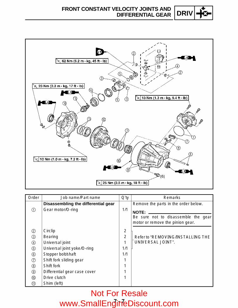
7 - 7
DRIVFRONT CONSTANT VELOCITY JOINTS AND
DIFFERENTIAL GEAR
Order Job name/Part name Q’ty Remarks
Disassembling the differential gear Remove the parts in the order below.1 Gear motor/O-ring 1/1
NOTE:Be sure not to disassemble the gearmotor or remove the pinion gear.
2 Circlip 2
Refer to “REMOVING/INSTALLING THE UNIVERSAL JOINT”.
3 Bearing 24 Universal joint 15 Universal joint yoke/O-ring 1/16 Stopper bolt/shaft 1/17 Shift fork sliding gear 18 Shift fork 19 Differential gear case cover 10 Drive clutch 1A Shim (left)
Not For Resale www.SmallEngineDiscount.com
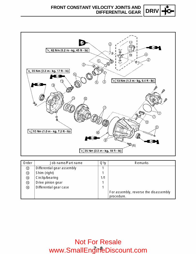
7 - 8
DRIVFRONT CONSTANT VELOCITY JOINTS AND
DIFFERENTIAL GEAR
Order Job name/Part name Q’ty Remarks
B Differential gear assembly 1C Shim (right) 1D Circlip/bearing 1/1E Drive pinion gear 1F Differential gear case 1
For assembly, reverse the disassembly procedure.
Not For Resale www.SmallEngineDiscount.com
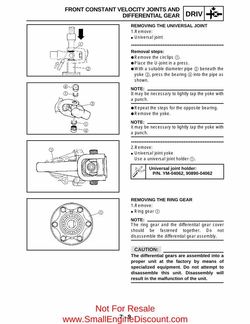
7 - 9
DRIV
REMOVING THE UNIVERSAL JOINT1.Remove: Universal joint
*****************************************************Removal steps: Remove the circlips 1. Place the U-joint in a press. With a suitable diameter pipe 2 beneath the
yoke 3, press the bearing 4 into the pipe asshown.
NOTE:It may be necessary to lightly tap the yoke witha punch.
Repeat the steps for the opposite bearing. Remove the yoke.
NOTE:it may be necessary to lightly tap the yoke witha punch.
*****************************************************2.Remove: Universal joint yoke
Use a universal joint holder 1.
Universal joint holder:P/N. YM-04062, 90890-04062
REMOVING THE RING GEAR1.Remove: Ring gear 1
NOTE:The ring gear and the differential gear covershould be fastened together. Do notdisassemble the differential gear assembly.
CAUTION:The differential gears are assembled into aproper unit at the factory by means ofspecialized equipment. Do not attempt todisassemble this unit. Disassembly willresult in the malfunction of the unit.
FRONT CONSTANT VELOCITY JOINTS ANDDIFFERENTIAL GEAR
Not For Resale www.SmallEngineDiscount.com

7 - 10
DRIVFRONT CONSTANT VELOCITY JOINTS AND
DIFFERENTIAL GEAR
CHECKING THE CONSTANT VELOCITY JOINT1.Check: Double off-set joint spline Ball joint spline Shaft spline
Wear/damage → Replace.2.Check: Dust boots
Cracks/damage → Replace.
CAUTION:Always use a new boot band.
3.Check: Balls and ball races Inner surface of double off-set joint
Pitting/wear/damage → Replace.
CHECKING THE DIFFERENTIAL GEAR1.Check: Gear teeth
Pitting/galling/wear → Replace drive piniongear and ring gear as a set.
Bearing Pitting/damage → Replace.
Oil seal O-ring
Damage → Replace.2.Check: Drive shaft splines Universal joints Front drive gear splines
Wear/damage → Replace. Spring
Fatigue → Replace.Move the spring up and down.
3.Check: Front drive shaft
Bends → Replace.
WARNINGDo not attempt to straighten a bent shaft;this may dangerously weaken the shaft.
Not For Resale www.SmallEngineDiscount.com
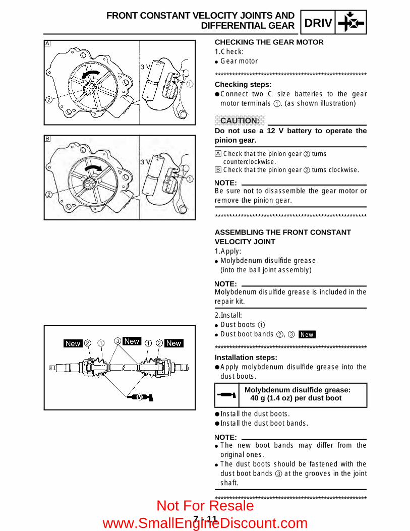
7 - 11
DRIVFRONT CONSTANT VELOCITY JOINTS AND
DIFFERENTIAL GEAR
CHECKING THE GEAR MOTOR1.Check: Gear motor
*****************************************************Checking steps: Connect two C size batteries to the gear
motor terminals 1. (as shown illustration)
CAUTION:Do not use a 12 V battery to operate thepinion gear.
È Check that the pinion gear 2 turns counterclockwise.
É Check that the pinion gear 2 turns clockwise.
NOTE:Be sure not to disassemble the gear motor orremove the pinion gear.
*****************************************************
È
É
ASSEMBLING THE FRONT CONSTANT VELOCITY JOINT1.Apply: Molybdenum disulfide grease
(into the ball joint assembly)
NOTE:Molybdenum disulfide grease is included in therepair kit.
2.Install: Dust boots 1 Dust boot bands 2, 3
*****************************************************Installation steps: Apply molybdenum disulfide grease into the
dust boots.
Install the dust boots. Install the dust boot bands.
NOTE: The new boot bands may differ from the
original ones. The dust boots should be fastened with the
dust boot bands 3 at the grooves in the jointshaft.
*****************************************************
Molybdenum disulfide grease:40 g (1.4 oz) per dust boot
New
Not For Resale www.SmallEngineDiscount.com

7 - 12
DRIVFRONT CONSTANT VELOCITY JOINTS AND
DIFFERENTIAL GEAR
3.Check: Free play (thrust movement)
Excessive play → Replace the joint assembly.
ASSEMBLING THE DIFFERENTIAL GEAR1.Measure: Gear lash
Refer to “MEASURING AND ADJUSTINGTHE DIFFERENTIAL GEAR LASH”.
2.Install: Gear motor
*****************************************************Installation steps: Slide the shift fork sliding gear 1, which is
installed to the differential gear, to the left toput it into the 2WD mode.
Connect two C size batteries to the gearmotor terminal 2 to operate the pinion gear3, and operate it until the paint mark 4 onthe gear is aligned with the paint mark 5 onthe gear motor case.
CAUTION:Do not use a 12 V battery to operate thepinion gear.
Insert 8 mm bolts 6 into the gear motor 7and use them as a guide to set the motor onthe differential gear assembly 8 so that theshift fork sliding gear 9 does not move.
CAUTION:If the position of the shift fork sliding gearis moved, the position of the differentialgear and the indicator light display maydiffer, and the 2WD or differential lockmode may not be activated.
Remove the 8 mm bolts, and then install themotor with the gear motor bolts.
*****************************************************
T R..
Bolts (gear motor)13 Nm (1.3 m • kg, 9.4 ft • lb)
Not For Resale www.SmallEngineDiscount.com
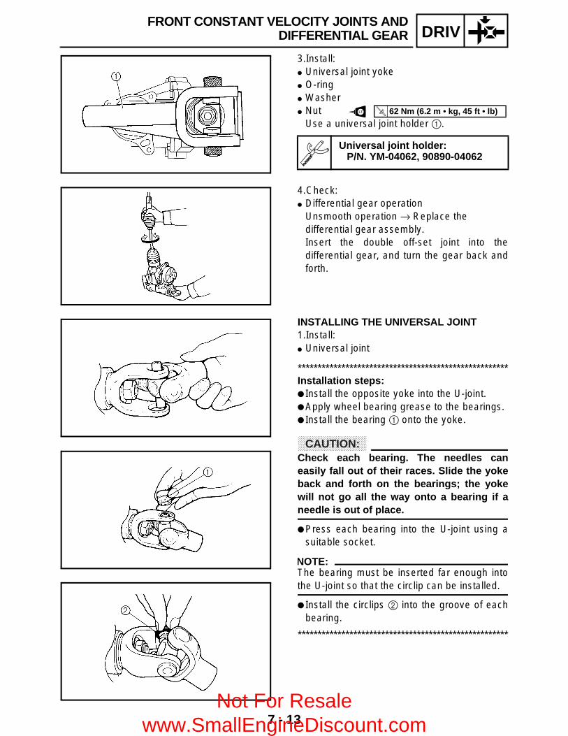
7 - 13
DRIVFRONT CONSTANT VELOCITY JOINTS AND
DIFFERENTIAL GEAR
3.Install: Universal joint yoke O-ring Washer Nut
Use a universal joint holder 1.
Universal joint holder:P/N. YM-04062, 90890-04062
LT
T R..
62 Nm (6.2 m • kg, 45 ft • lb)
4.Check: Differential gear operation
Unsmooth operation → Replace the differential gear assembly.Insert the double off-set joint into thedifferential gear, and turn the gear back andforth.
INSTALLING THE UNIVERSAL JOINT1.Install: Universal joint
*****************************************************Installation steps: Install the opposite yoke into the U-joint. Apply wheel bearing grease to the bearings. Install the bearing 1 onto the yoke.
CAUTION:Check each bearing. The needles caneasily fall out of their races. Slide the yokeback and forth on the bearings; the yokewill not go all the way onto a bearing if aneedle is out of place.
Press each bearing into the U-joint using asuitable socket.
NOTE:The bearing must be inserted far enough intothe U-joint so that the circlip can be installed.
Install the circlips 2 into the groove of eachbearing.
*****************************************************
Not For Resale www.SmallEngineDiscount.com

7 - 14
DRIV
MEASURING AND ADJUSTING THE DIFFERENTIAL GEAR LASHMeasuring the differential gear lash1.Secure the gear case in a vise or another
supporting device.2.Remove: Drain plug Gasket3.Install: A bolt of the specified size 1
(into the drain plug hole)
CAUTION:Finger tighten the bolt until it holds the ringgear. Otherwise, the ring gear will bedamaged.
4.Attach: Gear lash measurement tool 1 Dial gauge 2
a Measuring point is 21 mm (0.83 in)
5.Measure: Gear lash
Gently rotate the gear coupling fromengagement to engagement.
NOTE:Measure the gear lash at four positions. Rotatethe shaft 90° each time.
Gear lash measurement tool:P/N. YM-01467, 90890-01467
Differential gear lash:0.05 ~ 0.25 mm (0.0020 ~ 0.0098 in)
FRONT CONSTANT VELOCITY JOINTS ANDDIFFERENTIAL GEAR
Not For Resale www.SmallEngineDiscount.com
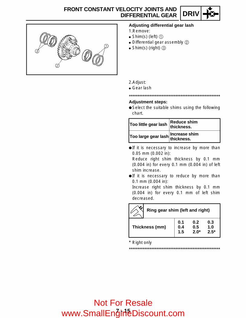
7 - 15
DRIV
Adjusting differential gear lash1.Remove: Shim(s) (left) 1 Differential gear assembly 2 Shim(s) (right) 3
2.Adjust: Gear lash
*****************************************************Adjustment steps: Select the suitable shims using the following
chart.
If it is necessary to increase by more than0.05 mm (0.002 in):Reduce right shim thickness by 0.1 mm(0.004 in) for every 0.1 mm (0.004 in) of leftshim increase.
If it is necessary to reduce by more than0.1 mm (0.004 in):Increase right shim thickness by 0.1 mm(0.004 in) for every 0.1 mm of left shimdecreased.
* Right only
*****************************************************
Too little gear lash Reduce shim thickness.
Too large gear lash Increase shim thickness.
Ring gear shim (left and right)
Thickness (mm)0.1 0.2 0.30.4 0.5 1.01.5 2.0* 2.5*
FRONT CONSTANT VELOCITY JOINTS ANDDIFFERENTIAL GEAR
Not For Resale www.SmallEngineDiscount.com
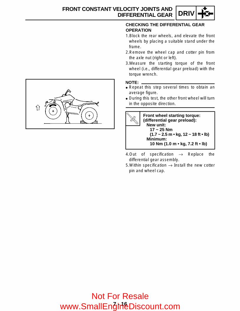
7 - 16
DRIV
CHECKING THE DIFFERENTIAL GEAR OPERATION 1.Block the rear wheels, and elevate the front
wheels by placing a suitable stand under theframe.
2.Remove the wheel cap and cotter pin fromthe axle nut (right or left).
3.Measure the starting torque of the frontwheel (i.e., differential gear preload) with thetorque wrench.
NOTE: Repeat this step several times to obtain an
average figure. During this test, the other front wheel will turn
in the opposite direction.
4.Out of specification → Replace thedifferential gear assembly.
5.Within specification → Install the new cotterpin and wheel cap.
T R..
Front wheel starting torque:(differential gear preload):
New unit:17 ~ 25 Nm (1.7 ~ 2.5 m • kg, 12 ~ 18 ft • lb)
Minimum:10 Nm (1.0 m • kg, 7.2 ft • lb)
FRONT CONSTANT VELOCITY JOINTS ANDDIFFERENTIAL GEAR
Not For Resale www.SmallEngineDiscount.com

7 - 17
DRIVREAR AXLE/FINAL DRIVE GEAR AND DRIVE SHAFT
REAR AXLE/FINAL DRIVE GEAR AND DRIVE SHAFT
Order Job name/Part name Q’ty Remarks
Removing the rear axle, final drive gear assembly and drive shaft
Remove the parts in the order below.
Final gear oil Drain.Rear wheel hubs/brake disc Refer to “FRONT AND REAR WHEELS”
in CHAPTER 8.1 O-ring 12 Rear axle/dust cover 1/1
Refer to “REMOVING/INSTALLING THE REAR AXLE”.
3 Trailer hitch bracket 14 Final drive gear case breather hose 1 Disconnect.5 Final drive gear 16 Drive shaft 1
For installation, reverse the removal procedure.
Not For Resale www.SmallEngineDiscount.com
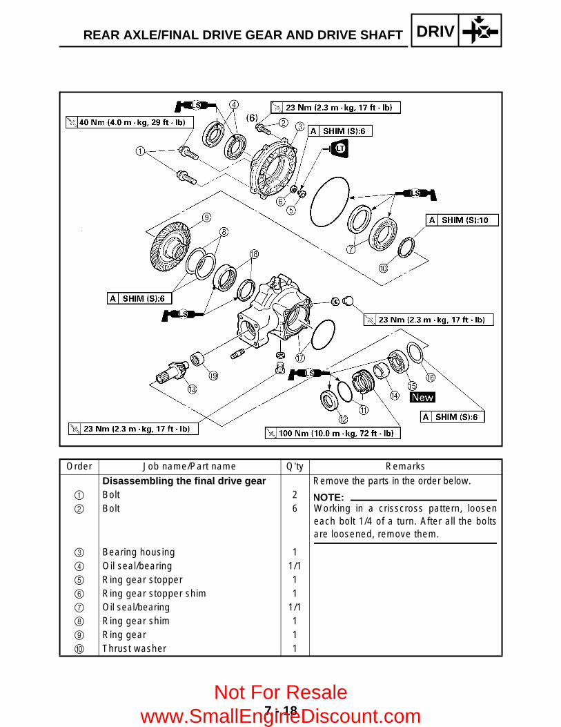
7 - 18
DRIVREAR AXLE/FINAL DRIVE GEAR AND DRIVE SHAFT
Order Job name/Part name Q’ty Remarks
Disassembling the final drive gear Remove the parts in the order below.1 Bolt 22 Bolt 6
3 Bearing housing 14 Oil seal/bearing 1/15 Ring gear stopper 16 Ring gear stopper shim 17 Oil seal/bearing 1/18 Ring gear shim 19 Ring gear 10 Thrust washer 1
NOTE:Working in a crisscross pattern, looseneach bolt 1/4 of a turn. After all the boltsare loosened, remove them.
Not For Resale www.SmallEngineDiscount.com

7 - 19
DRIVREAR AXLE/FINAL DRIVE GEAR AND DRIVE SHAFT
Order Job name/Part name Q’ty Remarks
A Bearing retainer/O-ring 1/1
Refer to “DISASSEMBLING/ASSEMBLING THE FINAL DRIVE GEAR”.
B Oil seal 1C Final drive pinion gear 1D Collar 1E Bearing 1F Final drive pinion gear shim 1G Final drive gear case/O-ring 1/1H Bearing/oil seal 1/1 Refer to “REPLACING THE FINAL
DRIVE ROLLER BEARING”.I Bearing 1For assembly, reverse the disassembly procedure.
Not For Resale www.SmallEngineDiscount.com

7 - 20
DRIVREAR AXLE/FINAL DRIVE GEAR AND DRIVE SHAFT
REMOVING THE REAR AXLE 1.Remove: Rear axle 1
(with dust seal) O-ring
CAUTION: Never directly tap the axle end with a
hammer, since this will result in damageto the axle thread and spline.
Attach a suitable socket 2 on the axleend and tap it with a soft hammer. Pull outthe rear axle to the right.
DISASSEMBLING THE FINAL DRIVE GEAR 1.Remove: Bearing retainer (final drive pinion gear)
NOTE:Use a bearing retainer wrench 1.
CAUTION:The final drive shaft bearing retainer hasleft-handed threads. To loosen the retainer,turn it clockwise.
2.Remove: Final drive pinion gear assembly
With a soft hammer, lightly tap on the finaldrive pinion gear end.
CAUTION:Removal of the final drive pinion gearshould only be performed if gearreplacement is necessary.
WARNINGAlways use new bearings and races.
Bearing retainer wrench:P/N. YM-04050, 90890-04050
Not For Resale www.SmallEngineDiscount.com

7 - 21
DRIVREAR AXLE/FINAL DRIVE GEAR AND DRIVE SHAFT
REPLACING THE FINAL DRIVE ROLLER BEARING 1.Remove: Roller bearing (ring gear) 1
Use a suitable press tool 2 and anappropriate support for the main housing.
Oil seal 3
2.Remove: Roller bearing (final drive pinion gear) 1
*****************************************************Removal steps: Heat the main housing only to 150 °C
(302 °F). Remove the roller bearing outer race with an
appropriately shaped punch 2. Remove the inner race from the final drive
pinion gear.
NOTE:The removal of the final drive pinion gear rollerbearing is difficult and seldom necessary.
*****************************************************
3.Install: Roller bearing (final drive pinion gear)
*****************************************************Installation steps: Heat the main housing only to 150 °C
(302 °F). Install the roller bearing outer race using the
proper adapter. Install the inner race onto the drive pinion
gear.
*****************************************************4.Install: Oil seal 1 Roller bearing 2
Use a suitable press tool 3 and a press toinstall the above components into the mainhousing.
New
New
Not For Resale www.SmallEngineDiscount.com

7 - 22
DRIVREAR AXLE/FINAL DRIVE GEAR AND DRIVE SHAFT
POSITIONING THE FINAL DRIVE PINION GEAR AND RING GEAR When the final drive pinion gear, ring gear,final gear case and/or ring gear bearinghousing are replaced, be sure to adjust thepositions of the final drive pinion gear and ringgear using the shim(s).
Final drive pinion gear shim selection1.Select: Final drive pinion gear shim(s) 1
*****************************************************Selection steps: To find the final drive pinion gear shim
thickness “A”, use the following formula.
a = a numeral (usually a decimal number)on the final drive pinion gear eitheradded to or subtracted from “84”
b = a numeral (usually a decimal number)on the final gear case either added to orsubtracted from “83”
Example:1) If “01” is stamped on the final drive
pinion gear,a = 84 + 0.01 = 84.01
2) If “50” is stamped on the final gear case,b = 83 + 0.50 = 83.50
3) Therefore, “A” is 0.51.“A”= 84.01 – 83.50
= 0.514) Round off the hundredth digit and select
the appropriate shim(s).In the example above, the calculatednumber is 0.51. The chart instructs youto round off 1 to 0 at the hundredthplace. Thus, the shim thickness is0.50 mm.
Final drive pinion gear shim thickness:“A” = a – b
Hundredths Rounded value
0, 1, 2 0
3, 4, 5, 6, 7 5
8, 9 10
Not For Resale www.SmallEngineDiscount.com

7 - 23
DRIVREAR AXLE/FINAL DRIVE GEAR AND DRIVE SHAFT
Shims are supplied in the followingthicknesses.
*****************************************************
Final drive pinion gear shim
Thickness (mm) 0.15 0.30 0.400.45 0.50 0.60
Ring gear shim selection1.Select: Ring gear shim(s) 1
*****************************************************Selection steps: To find the ring gear shim thickness “B”, use
the following formula.
c = a numeral (usually a decimal number)on the final gear case either added to orsubtracted from 45
d = a numeral (usually a decimal number)on the outside of the ring gear bearinghousing and added to 1
e = a numeral (usually a decimal number)on the inside of the ring gear eitheradded to or subtracted from 35.00
f = bearing thickness (considered constant)
Example:1) If “53” is stamped on the final gear case,
c = 45 + 0.53 = 45.532) If “05” is stamped on the ring gear
bearing housing,d = 1 + 0.05
= 1.053) If “– 05” is stamped on the ring gear,
e = 35 – 0.05= 34.95
4) f = 11.00.
Ring gear shim thickness:“B” = c + d – (e + f)
Bearing thickness f:11.00 mm
Not For Resale www.SmallEngineDiscount.com

7 - 24
DRIVREAR AXLE/FINAL DRIVE GEAR AND DRIVE SHAFT
5) Therefore, shim thickness “B” is 0.63.“B”= 45.53 + 1.05 – (34.95 + 11.00)
= 46.58 – 45.95= 0.63
6) Round off the hundredth digit and selectthe appropriate shim(s).In the example above, the calculatednumber is 0.63. The chart instructs youto round off 3 to 5 at the hundredthplace.Thus, the shim thickness is 0.65 mm.
Shims are supplied in the followingthicknesses.
*****************************************************
Hundredths Rounded value
0, 1, 2 0
3, 4, 5, 6, 7 5
8, 9 10
Ring gear shim
Thickness (mm) 0.25 0.30 0.350.40 0.45 0.50
Thrust washer selection1.Measure/select: Ring gear thrust clearance “C”
*****************************************************Measurement steps: Place four pieces of Plastigauge® between
the originally fitted thrust washer and the ringgear.
Install the ring gear assembly and tighten thebolts to specification.
NOTE:Do not turn the drive pinion gear and ring gearwhen measuring the clearance withPlastigauge®.
T R..
M8 Bolts (bearing housing):23 Nm (2.3 m • kg, 17 ft • lb)
M10 Bolts (bearing housing):40 Nm (4.0 m • kg, 29 ft • lb)
Not For Resale www.SmallEngineDiscount.com

7 - 25
DRIVREAR AXLE/FINAL DRIVE GEAR AND DRIVE SHAFT
Remove the ring gear assembly. Measure the thrust clearance. Calculate the
width of the flattened Plastigauge® 1.
If out of specification, select the correctwasher.
Ring gear thrust clearance:0.1 ~ 0.2 mm (0.004 ~ 0.008 in)
Thrust washer selection steps: Select a suitable thrust washer using the
following chart.
Repeat the measurement steps until the ringgear thrust clearance is within the specifiedlimits.
*****************************************************
Thrust washer
Thickness (mm)
1.0 1.1 1.21.3 1.35 1.41.45 1.5 1.551.6 1.7 1.81.9 2.0 2.1
Ring gear stopper shim selection1.Measure: Ring gear stopper clearance “D”
Use a feeler gauge 1. Out of specification → Adjust.
2 Ring gear3 Ring gear stopper
Ring gear stopper clearance “D”:0.30 ~ 0.60 mm (0.012 ~ 0.024 in)
Not For Resale www.SmallEngineDiscount.com

7 - 26
DRIVREAR AXLE/FINAL DRIVE GEAR AND DRIVE SHAFT
Ring gear stopper clearance adjustment1.Remove: Ring gear 1 Ring gear stopper 2 Shim(s) 3 4 Bearing housingÈ Left-hand threads
2.Select: Suitable shim(s)
Shim
Thickness (mm) 0.10 0.15 0.200.30 0.40 0.50
3.Install: Shim(s) Ring gear stopper (left-hand threads)
Ring gear
NOTE:Use LOCTITE on the ring gear stopper.
T R..
9 Nm (0.9 m • kg, 6.5 ft • lb)
4.Measure: Ring gear stopper clearance
Out of specification → Repeat adjustmentsteps.
CHECKING THE REAR AXLE 1.Check: Rear axle runout a
Out of specification → Replace.
WARNINGDo not attempt to straighten a bent axle.
Ring gear stopper clearance:0.30 ~ 0.60 mm (0.012 ~ 0.024 in)
Rear axle runout limit:1.5 mm (0.06 in)
Not For Resale www.SmallEngineDiscount.com
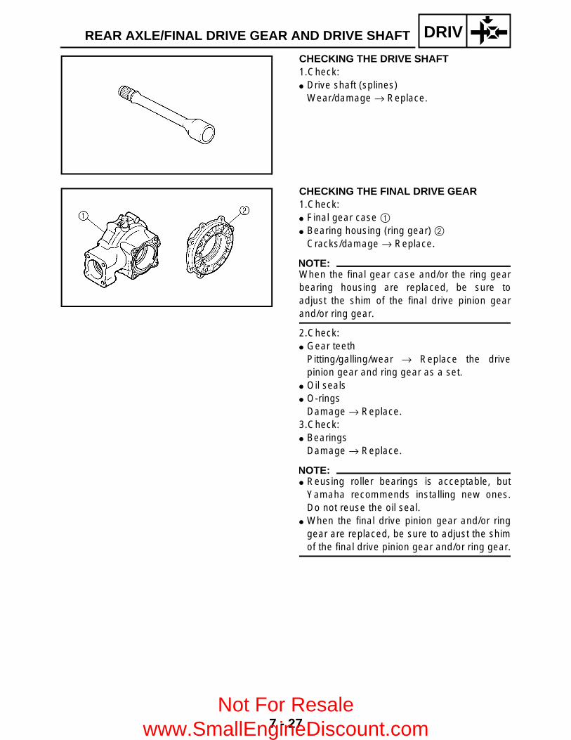
7 - 27
DRIVREAR AXLE/FINAL DRIVE GEAR AND DRIVE SHAFT
CHECKING THE DRIVE SHAFT 1.Check: Drive shaft (splines)
Wear/damage → Replace.
CHECKING THE FINAL DRIVE GEAR 1.Check: Final gear case 1 Bearing housing (ring gear) 2
Cracks/damage → Replace.
NOTE:When the final gear case and/or the ring gearbearing housing are replaced, be sure toadjust the shim of the final drive pinion gearand/or ring gear.
2.Check: Gear teeth
Pitting/galling/wear → Replace the drivepinion gear and ring gear as a set.
Oil seals O-rings
Damage → Replace.3.Check: Bearings
Damage → Replace.
NOTE: Reusing roller bearings is acceptable, but
Yamaha recommends installing new ones.Do not reuse the oil seal.
When the final drive pinion gear and/or ringgear are replaced, be sure to adjust the shimof the final drive pinion gear and/or ring gear.
Not For Resale www.SmallEngineDiscount.com

7 - 28
DRIVREAR AXLE/FINAL DRIVE GEAR AND DRIVE SHAFT
MEASUREMENT AND ADJUSTING THE FINAL GEAR LASH Final gear lash measurement1.Secure the gear case in a vise or another
supporting device.2.Remove: Drain plug Gasket3.Install: A bolt of the specified size 1
(into the drain plug hole)
CAUTION:Finger tighten the bolt until it holds the ringgear. Otherwise, the ring gear will bedamaged.
4.Attach: Gear lash measurement tool 1 Dial gauge 2
a Measuring point is 31.46 mm (1.24 in)
Gear lash measurement tool:P/N. YM-01475, 90890-01475
5.Measure: Gear lash
Gently rotate the gear coupling fromengagement to engagement.
NOTE:Measure the gear lash at four positions. Rotatethe shaft 90° each time.
Final gear lash:0.1 ~ 0.2 mm (0.004 ~ 0.008 in)
Not For Resale www.SmallEngineDiscount.com

7 - 29
DRIVREAR AXLE/FINAL DRIVE GEAR AND DRIVE SHAFT
Final gear lash adjustment1.Remove: Bearing housing 1 Ring gear shim(s) 2 Ring gear 3 Thrust washer 4
2.Adjust: Gear lash
*****************************************************Adjustment steps: Select a suitable shim(s) and thrust
washer(s) using the following chart.
If increased by more than 0.2 mm (0.008 in):Reduce the thrust washer thickness by0.2 mm (0.008 in) for every 0.2 mm(0.008 in) of ring gear shim increase.
If reduced by more than 0.2 mm (0.008 in):Increase the thrust washer thickness by0.2 mm (0.008 in) for every 0.2 mm(0.008 in) that the ring gear shim isdecreased.
*****************************************************
Too little gear lash Reduce shim thickness.
Too large gear lash Increase shim thickness.
Ring gear shim
Thickness (mm) 0.25 0.30 0.350.40 0.45 0.50
Thrust washer
Thickness (mm)
1.0 1.1 1.21.3 1.35 1.41.45 1.5 1.551.6 1.7 1.81.9 2.0 2.1
Not For Resale www.SmallEngineDiscount.com

7 - 30
DRIVREAR AXLE/FINAL DRIVE GEAR AND DRIVE SHAFT
ASSEMBLING THE FINAL DRIVE GEAR 1.Install: Drive pinion gear (with shim(s) and bearing)
(proper shim size as calculated) Bearing retainer (drive pinion gear) 1
Use a bearing retainer wrench 2.
CAUTION: Always use a new bearing. The final drive shaft bearing retainer has
left-hand threads. Turn the retainercounterclockwise to tighten it.
2.Adjust: Final gear lash
Refer to “MEASUREMENT ANDADJUSTING THE FINAL GEAR LASH”.
Bearing retainer wrench:P/N. YM-04050, 90890-04050
T R..
100 Nm (10.0 m • kg, 72 ft • lb)
INSTALLING THE FINAL DRIVE GEAR 1.Lubricate: Drive shaft Coupling gear O-ring Oil seal Bearing
2.Install: Drive shaft 1
(to the universal joint)
Lithium-soap-based grease
Not For Resale www.SmallEngineDiscount.com

7 - 31
DRIVREAR AXLE/FINAL DRIVE GEAR AND DRIVE SHAFT
3.Apply: Sealant (Quick Gasket®)
(to the mating surfaces of the swingarm andthe final drive gear case)
Sealant (Quick gasket®):P/N. ACC-11001-05-01
Yamaha bond No.1215:P/N. 90890-85505
4.Install: Final drive gear Nuts Bolts
LT
T R..
63 Nm (6.3 m • kg, 45 ft • lb)LT
T R..
63 Nm (6.3 m • kg, 45 ft • lb)
5.Install: Dust cover Rear axle
*****************************************************Installation steps: Install the dust cover 1 onto the rear axle.
NOTE:Adjust the length a to 210.1 mm (8.3 in) wheninstall the dust cover.
Install the rear axle (with dust cover) 2. Install the rear brake disc and rear wheel hub
(left). Temporarily tighten the left axle nut 3.
NOTE:After tightening the rear axle nut 3, theposition of the dust cover 1 will slightly moveto protect the oil seal of the final gear case.
*****************************************************
Not For Resale www.SmallEngineDiscount.com
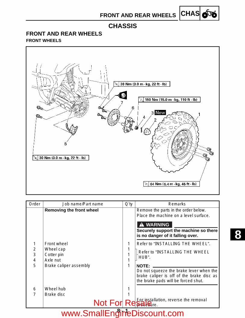
8 - 1
CHASFRONT AND REAR WHEELS
CHASSISFRONT AND REAR WHEELSFRONT WHEELS
Order Job name/Part name Q’ty RemarksRemoving the front wheel Remove the parts in the order below.
Place the machine on a level surface.
WARNINGSecurely support the machine so thereis no danger of it falling over.
1 Front wheel 1 Refer to “INSTALLING THE WHEEL”.2 Wheel cap 1
Refer to “INSTALLING THE WHEEL HUB”.
3 Cotter pin 14 Axle nut 15 Brake caliper assembly 1 NOTE:
Do not squeeze the brake lever when thebrake caliper is off of the brake disc asthe brake pads will be forced shut.
6 Wheel hub 17 Brake disc 1
For installation, reverse the removal procedure.
8
Not For Resale www.SmallEngineDiscount.com

8 - 2
CHASFRONT AND REAR WHEELS
REAR WHEELS
Order Job name/Part name Q’ty RemarksRemoving the rear wheel Remove the parts in the order below.
Place the machine on a level surface.
WARNINGSecurely support the machine so thereis no danger of it falling over.
1 Rear wheel 2 Refer to “INSTALLING THE WHEEL”.2 Wheel cap 2
Refer to “INSTALLING THE WHEEL HUB”.
3 Cotter pin 24 Axle nut 25 Wheel hub 26 Brake caliper mounting bolt 27 Brake disc bracket 18 Brake disc 19 Brake disc guard 1
For installation, reverse the removal procedure.Not For Resale
www.SmallEngineDiscount.com

8 - 3
CHASFRONT AND REAR WHEELS
CHECKING THE WHEEL1.Check: Wheel2.Measure: Wheel runout
Over the specified limit → Replace the wheelor check the wheel bearing play 1.
3.Check: Wheel balance
Out of balance → Adjust.
Wheel runout limit:Radial 2: 2.0 mm (0.08 in)Lateral 3: 2.0 mm (0.08 in)
WARNINGAfter replacing the tire, ride conservativelyto allow the tire to be properly seated in therim. Failure to do so may cause an accidentresulting in machine damage and possibleoperator injury.
CHECKING THE WHEEL HUB1.Check: Wheel hub 1
Cracks/damage → Replace. Splines (wheel hub) 2
Wear/damage → Replace.
Not For Resale www.SmallEngineDiscount.com

8 - 4
CHASFRONT AND REAR WHEELS
CHECKING THE BRAKE DISC1.Check: Brake disc
Galling/damage → Replace.2.Measure: Brake disc deflection
Out of specification → Check the wheelrunout.If wheel runout is within the limits, replacethe brake disc.
Brake disc thickness a Out of specification → Replace.
Brake disc maximum deflection:0.15 mm (0.006 in)
Brake disc minimum thickness:3 mm (0.12 in)
INSTALLING THE WHEEL HUB1.Install: Axle nut Cotter pin 1
NOTE:Do not loosen the axle nut after torquing it. Ifthe axle nut groove is not aligned with thecotter pin hole, align the groove with the holeby tightening the axle nut.
T R..
150 Nm (15.0 m • kg, 110 ft • lb)
New
INSTALLING THE WHEEL1.Install: Wheel
NOTE:The arrow mark 1 on the tire must point in thedirection of rotation È of the wheel.
Not For Resale www.SmallEngineDiscount.com

8 - 5
CHASFRONT AND REAR WHEELS
2.Install: Nuts (wheel) 1
WARNINGTapered wheel nuts 1 are used for both thefront and rear wheels. Install each nut withits tapered side towards the wheel.
3.Tighten: Nuts (front wheel)
Nuts (rear wheel)
NOTE:Tighten the nuts in stages and in a crisscrosspattern.
T R..
64 Nm (6.4 m • kg, 46 ft • lb)
T R..
55 Nm (5.5 m • kg, 40 ft • lb)
Not For Resale www.SmallEngineDiscount.com
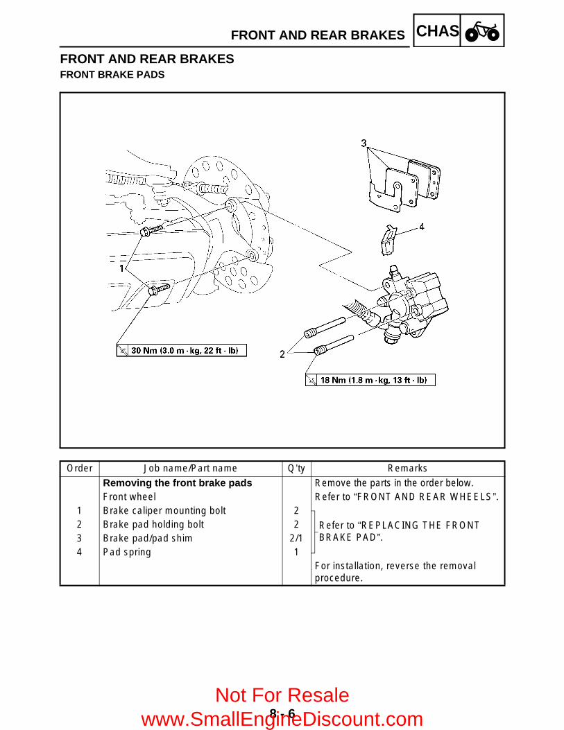
8 - 6
CHASFRONT AND REAR BRAKES
FRONT AND REAR BRAKESFRONT BRAKE PADS
Order Job name/Part name Q’ty Remarks
Removing the front brake pads Remove the parts in the order below.Front wheel Refer to “FRONT AND REAR WHEELS”.
1 Brake caliper mounting bolt 2
Refer to “REPLACING THE FRONT BRAKE PAD”.
2 Brake pad holding bolt 23 Brake pad/pad shim 2/14 Pad spring 1
For installation, reverse the removal procedure.
Not For Resale www.SmallEngineDiscount.com
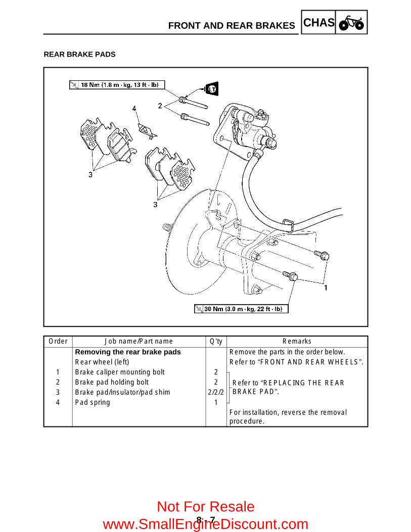
8 - 7
CHASFRONT AND REAR BRAKES
REAR BRAKE PADS
Order Job name/Part name Q’ty Remarks
Removing the rear brake pads Remove the parts in the order below.Rear wheel (left) Refer to “FRONT AND REAR WHEELS”.
1 Brake caliper mounting bolt 2
Refer to “REPLACING THE REAR BRAKE PAD”.
2 Brake pad holding bolt 23 Brake pad/insulator/pad shim 2/2/24 Pad spring 1
For installation, reverse the removal procedure.
Not For Resale www.SmallEngineDiscount.com

8 - 8
CHASFRONT AND REAR BRAKES
CAUTION:Disc brake components rarely requiredisassembly. DO NOT: disassemble components unless
absolutely necessary; use solvents on internal brake
components; use spent brake fluid for cleaning; (use
only clean brake fluid) allow brake fluid to come in contact with
the eyes, as this may cause eye injury; splash brake fluid onto painted surfaces or
plastic parts, as this may cause damage; disconnect any hydraulic connection, as
this would require the entire brakesystem to be disassembled, drained,cleaned, properly filled and bled afterreassembly.
REPLACING THE FRONT BRAKE PAD
NOTE:It is not necessary to disassemble the brakecaliper and brake hose to replace the brakepads.
1.Measure: Brake pad wear limit a
Out of specification → Replace the brakepad as a set.
Brake pad wear limit:1 mm (0.04 in)
2.Install: Brake pads Brake pad spring
NOTE:Always install new brake pads, brake pad shimand brake pad spring as a set.
Not For Resale www.SmallEngineDiscount.com

8 - 9
CHASFRONT AND REAR BRAKES
*****************************************************Installation steps: Connect a suitable hose 1 tightly to the
brake caliper bleed screw 2. Put the otherend of this hose into an open container.
Loosen the brake caliper bleed screw and,using a finger, push the caliper piston intothe brake caliper.
Tighten the brake caliper bleed screw.
Install new brake pads, new pad shims 3and a new brake pad spring.
Install the retaining bolts and brake caliper.
NOTE:The arrow mark a on the pad shim must pointin the direction of the disc rotation.
*****************************************************
T R..
Brake caliper bleed screw:6 Nm (0.6 m • kg, 4.3 ft • lb)
T R..
Brake pad holding bolt:18 Nm (1.8 m • kg, 13 ft • lb)
Brake caliper mounting bolt:30 Nm (3.0 m • kg, 22 ft • lb)
3.Check: Brake fluid level
Refer to “CHECKING THE BRAKE FLUIDLEVEL” in CHAPTER 3.
4.Check: Brake lever operation
Soft or spongy feeling → Bleed the frontbrake system.Refer to “BLEEDING THE HYDRAULICBRAKE SYSTEM” in CHAPTER 3.
Not For Resale www.SmallEngineDiscount.com
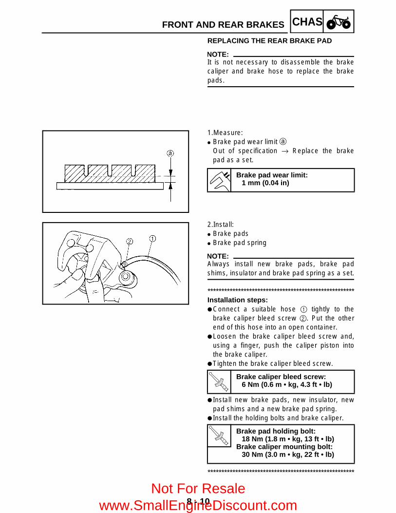
8 - 10
CHASFRONT AND REAR BRAKES
REPLACING THE REAR BRAKE PAD
NOTE:It is not necessary to disassemble the brakecaliper and brake hose to replace the brakepads.
1.Measure: Brake pad wear limit a
Out of specification → Replace the brakepad as a set.
Brake pad wear limit:1 mm (0.04 in)
2.Install: Brake pads Brake pad spring
NOTE:Always install new brake pads, brake padshims, insulator and brake pad spring as a set.
*****************************************************Installation steps: Connect a suitable hose 1 tightly to the
brake caliper bleed screw 2. Put the otherend of this hose into an open container.
Loosen the brake caliper bleed screw and,using a finger, push the caliper piston intothe brake caliper.
Tighten the brake caliper bleed screw.
Install new brake pads, new insulator, newpad shims and a new brake pad spring.
Install the holding bolts and brake caliper.
*****************************************************
T R..
Brake caliper bleed screw:6 Nm (0.6 m • kg, 4.3 ft • lb)
T R..
Brake pad holding bolt:18 Nm (1.8 m • kg, 13 ft • lb)
Brake caliper mounting bolt:30 Nm (3.0 m • kg, 22 ft • lb)
Not For Resale www.SmallEngineDiscount.com
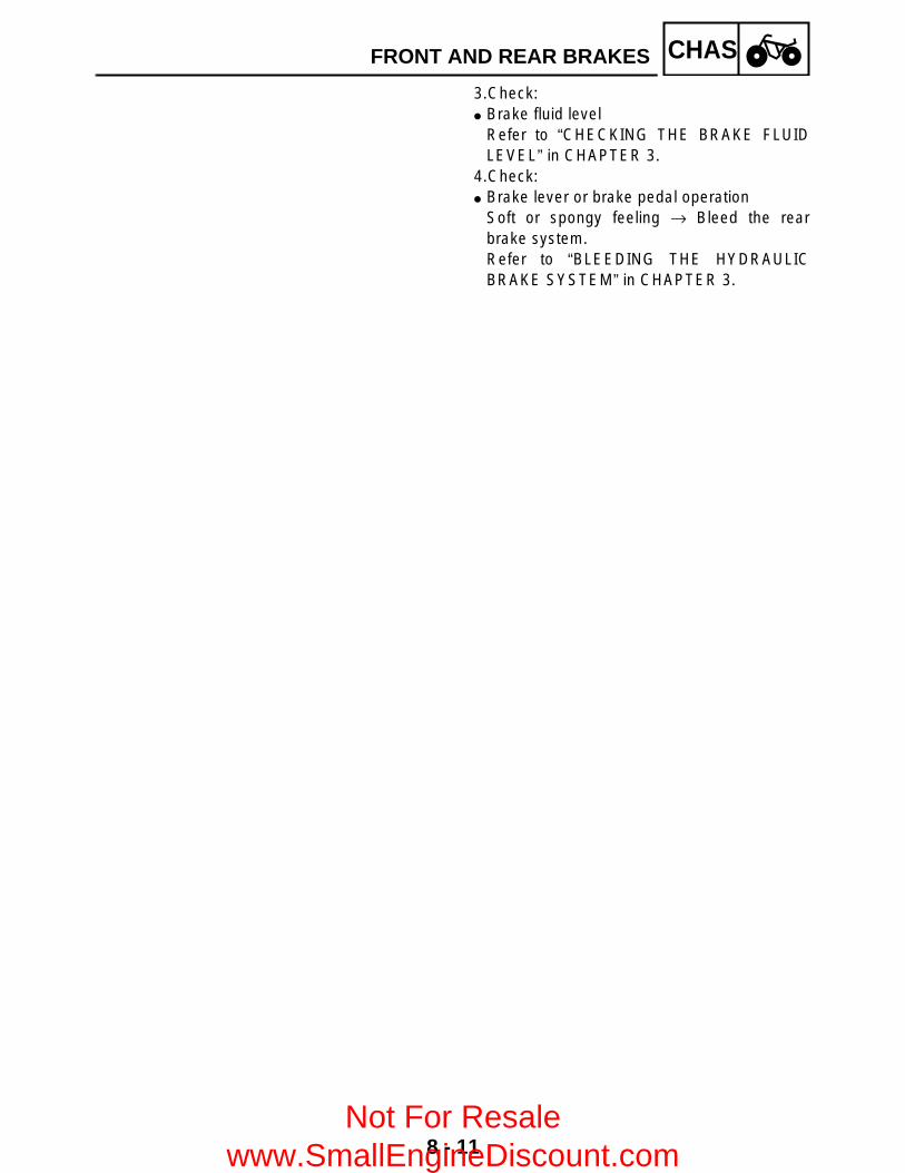
8 - 11
CHASFRONT AND REAR BRAKES
3.Check: Brake fluid level
Refer to “CHECKING THE BRAKE FLUIDLEVEL” in CHAPTER 3.
4.Check: Brake lever or brake pedal operation
Soft or spongy feeling → Bleed the rearbrake system.Refer to “BLEEDING THE HYDRAULICBRAKE SYSTEM” in CHAPTER 3.
Not For Resale www.SmallEngineDiscount.com
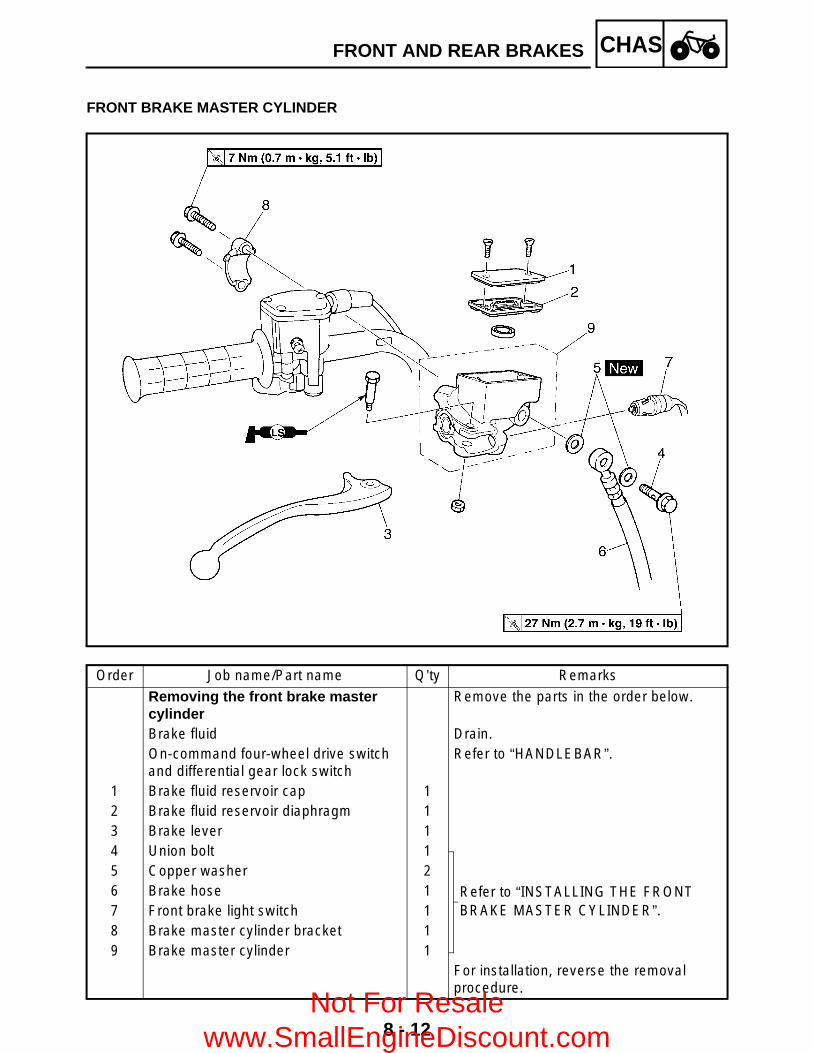
8 - 12
CHASFRONT AND REAR BRAKES
FRONT BRAKE MASTER CYLINDER
Order Job name/Part name Q’ty Remarks
Removing the front brake master cylinder
Remove the parts in the order below.
Brake fluid Drain.On-command four-wheel drive switch and differential gear lock switch
Refer to “HANDLEBAR”.
1 Brake fluid reservoir cap 12 Brake fluid reservoir diaphragm 13 Brake lever 14 Union bolt 1
Refer to “INSTALLING THE FRONT BRAKE MASTER CYLINDER”.
5 Copper washer 26 Brake hose 17 Front brake light switch 18 Brake master cylinder bracket 19 Brake master cylinder 1
For installation, reverse the removal procedure.
Not For Resale www.SmallEngineDiscount.com

8 - 13
CHASFRONT AND REAR BRAKES
Order Job name/Part name Q’ty Remarks
Disassembling the front brake master cylinder
Remove the parts in the order below.
1 Brake master cylinder kit 1 Refer to “ASSEMBLING THE FRONT BRAKE MASTER CYLINDER”.2 Brake master cylinder 1
For assembly, reverse the disassembly procedure.
Not For Resale www.SmallEngineDiscount.com

8 - 14
CHASFRONT AND REAR BRAKES
REAR BRAKE MASTER CYLINDER
Order Job name/Part name Q’ty Remarks
Removing the rear brake master cylinder
Remove the parts in the order below.
Front fender Refer to “SEAT, CARRIERS, FENDERS AND FUEL TANK” in CHAPTER 3.
Brake fluid Drain.1 Brake fluid reservoir cap 12 Brake fluid reservoir diaphragm holder 13 Brake fluid reservoir diaphragm 14 Brake fluid reservoir 15 Brake master cylinder cover 16 Brake fluid reservoir hose 17 Union bolt 1
Refer to “INSTALLING THE REAR BRAKE MASTER CYLINDER”.
8 Copper washer 29 Brake hose 1
Not For Resale www.SmallEngineDiscount.com

8 - 15
CHASFRONT AND REAR BRAKES
Order Job name/Part name Q’ty Remarks
10 Brake cable 1 Disconnect.11 Bracket 112 Brake master cylinder 113 Hose joint 114 Brake pedal 115 Select lever control cable 1 Disconnect.16 Rear brake light switch 117 Bracket 118 Bracket 119 Brake master cylinder bracket 1
For installation, reverse the removal procedure.
Not For Resale www.SmallEngineDiscount.com

8 - 16
CHASFRONT AND REAR BRAKES
Order Job name/Part name Q’ty Remarks
Disassembling the rear brake master cylinder
Remove the parts in the order below.
1 Brake master cylinder kit 1 Refer to “ASSEMBLING THE REAR BRAKE MASTER CYLINDER”.2 Brake master cylinder 1
For assembly, reverse the disassembly procedure.
Not For Resale www.SmallEngineDiscount.com
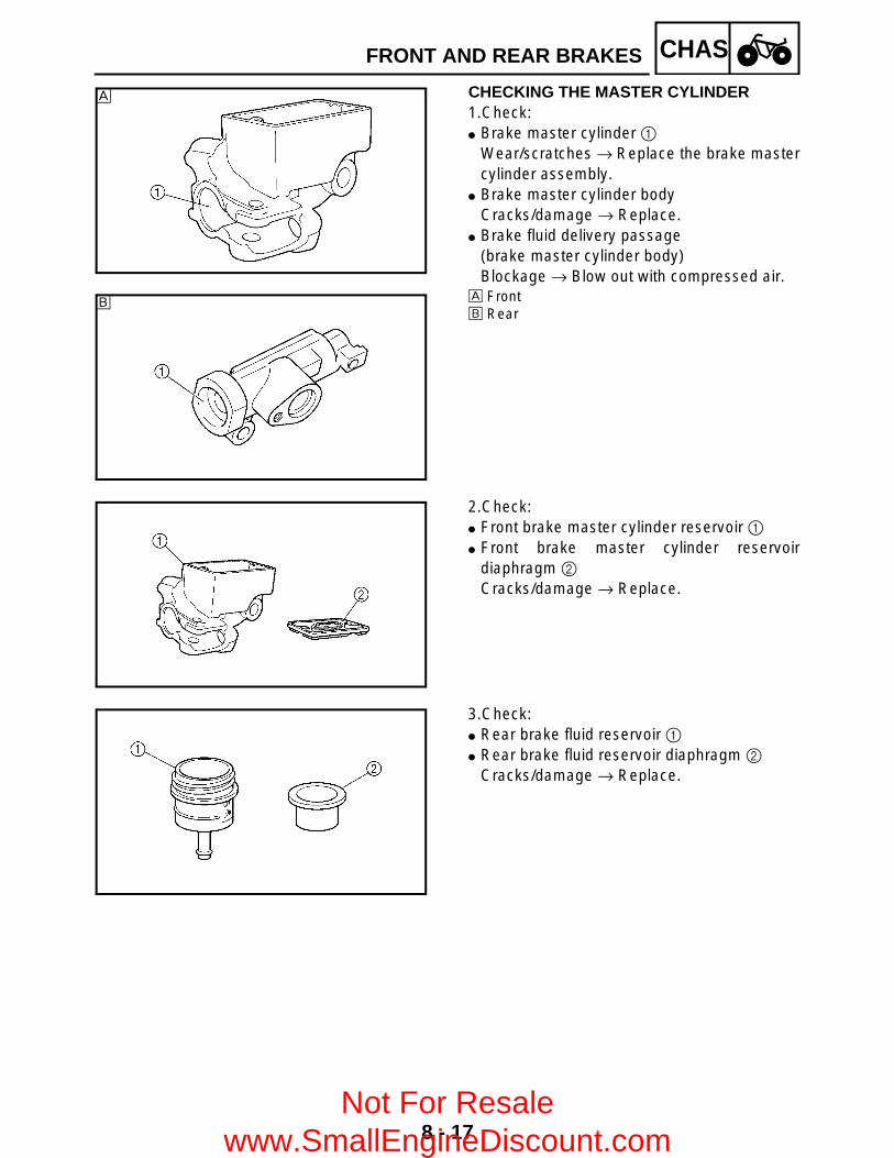
8 - 17
CHASFRONT AND REAR BRAKES
CHECKING THE MASTER CYLINDER1.Check: Brake master cylinder 1
Wear/scratches → Replace the brake mastercylinder assembly.
Brake master cylinder bodyCracks/damage → Replace.
Brake fluid delivery passage(brake master cylinder body)Blockage → Blow out with compressed air.
È FrontÉ Rear
È
É
2.Check: Front brake master cylinder reservoir 1 Front brake master cylinder reservoir
diaphragm 2 Cracks/damage → Replace.
3.Check: Rear brake fluid reservoir 1 Rear brake fluid reservoir diaphragm 2
Cracks/damage → Replace.
Not For Resale www.SmallEngineDiscount.com

8 - 18
CHASFRONT AND REAR BRAKESEB702060
ASSEMBLING THE FRONT BRAKE MASTER CYLINDER
WARNING All internal brake components should be
cleaned and lubricated with new brakefluid only before installation.
Whenever a master cylinder isdisassembled, replace the piston sealsand dust seals.
Recommended brake fluid:DOT 4
EB702060
ASSEMBLING THE REAR BRAKE MASTER CYLINDER
WARNING All internal brake components should be
cleaned and lubricated with new brakefluid only before installation.
Whenever a master cylinder isdisassembled, replace the piston sealsand dust seals.
1.Install: Brake master cylinder kit Nut 1 Joint 2
NOTE:Turn the adjusting bolt 3 until the clearance ais within the specified limits when install thejoint 2.
2.Tighten: Nut 1
Recommended brake fluid:DOT 4
Clearance a:4 ~ 6 mm (0.16 ~ 0.24 in)
Not For Resale www.SmallEngineDiscount.com

8 - 19
CHASFRONT AND REAR BRAKES
INSTALLING THE FRONT BRAKE MASTER CYLINDER 1.Install: Brake master cylinder 1 Brake master cylinder bracket 2
NOTE:The “UP” mark on the brake master cylinderbracket 2 should face up.
2.Install: Copper washers Brake hose Union bolt
NOTE: Tighten the union bolt while holding the
brake hose as shown. Turn the handlebar to the left and to the right
to check that the brake hose does not touchother parts (throttle cable, wire harness,leads, etc.). Correct if necessary.
WARNINGProper brake hose routing is essential toinsure safe machine operation. Refer to“CABLE ROUTING” in CHAPTER 2.
3.Fill: Brake fluid reservoir
CAUTION:Brake fluid may damage painted surfacesor plastic parts. Always clean up spilledbrake fluid immediately.
WARNING Use only the designated quality brake
fluid: other brake fluids may deterioratethe rubber seals, causing leakage andpoor brake performance.
Refill with the same type of brake fluid:mixing brake fluids may result in aharmful chemical reaction and lead topoor brake performance.
Recommended brake fluid:DOT 4
T R..
7 Nm (0.7 m • kg, 5.1 ft • lb)
60˚
New
T R..
27 Nm (2.7 m • kg, 19 ft • lb)
Not For Resale www.SmallEngineDiscount.com
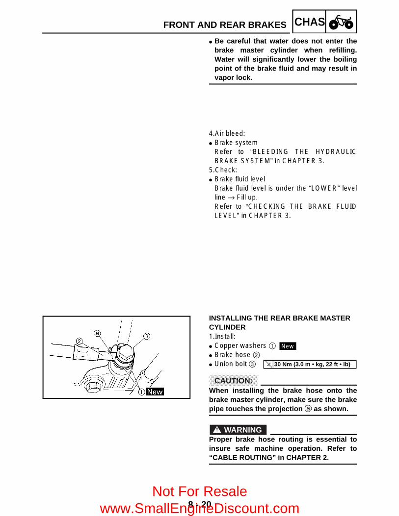
8 - 20
CHASFRONT AND REAR BRAKES
Be careful that water does not enter thebrake master cylinder when refilling.Water will significantly lower the boilingpoint of the brake fluid and may result invapor lock.
4.Air bleed: Brake system
Refer to “BLEEDING THE HYDRAULICBRAKE SYSTEM” in CHAPTER 3.
5.Check: Brake fluid level
Brake fluid level is under the “LOWER” levelline → Fill up.Refer to “CHECKING THE BRAKE FLUIDLEVEL” in CHAPTER 3.
INSTALLING THE REAR BRAKE MASTER CYLINDER1.Install: Copper washers 1 Brake hose 2 Union bolt 3
CAUTION:When installing the brake hose onto thebrake master cylinder, make sure the brakepipe touches the projection a as shown.
WARNINGProper brake hose routing is essential toinsure safe machine operation. Refer to“CABLE ROUTING” in CHAPTER 2.
New
T R..
30 Nm (3.0 m • kg, 22 ft • lb)
Not For Resale www.SmallEngineDiscount.com

8 - 21
CHASFRONT AND REAR BRAKES
2.Fill: Brake fluid reservoir
CAUTION:Brake fluid may damage painted surfacesor plastic parts. Always clean up spilledbrake fluid immediately.
WARNING Use only the designated quality brake
fluid: other brake fluids may deterioratethe rubber seals, causing leakage andpoor brake performance.
Refill with the same type of brake fluid:mixing brake fluids may result in aharmful chemical reaction and lead topoor brake performance.
Be careful that water does not enter thebrake master cylinder when refilling.Water will significantly lower the boilingpoint of the brake fluid and may result invapor lock.
Recommended brake fluid:DOT 4
3.Air bleed: Brake system
Refer to “BLEEDING THE HYDRAULICBRAKE SYSTEM” in CHAPTER 3.
4.Check: Brake fluid level
Brake fluid level is under the “LOWER” levelline → Fill up.Refer to “CHECKING THE BRAKE FLUIDLEVEL” in CHAPTER 3.
Not For Resale www.SmallEngineDiscount.com

8 - 22
CHASFRONT AND REAR BRAKES
FRONT BRAKE CALIPER
Order Job name/Part name Q’ty Remarks
Removing the front brake caliper Remove the parts in the order below.Brake fluid Drain.Front wheel Refer to “FRONT AND REAR WHEELS”.
1 Union bolt 1
Refer to “INSTALLING THE FRONT BRAKE CALIPER”.
2 Copper washer 23 Brake hose 1 Disconnect.4 Cap/retaining bolt 1/1 Loosen.5 Brake pad holding bolt 2 Loosen.6 Brake caliper mounting bolt 27 Brake caliper assembly 1
For installation, reverse the removal procedure.
Not For Resale www.SmallEngineDiscount.com

8 - 23
CHASFRONT AND REAR BRAKES
Order Job name/Part name Q’ty Remarks
Disassembling the front brake caliper
Remove the parts in the order below.
1 Brake pad holding bolt 22 Brake pad/pad shim 2/13 Pad spring 14 Retaining bolt 15 Caliper bracket 16 Brake caliper piston 1 Refer to “DISASSEMBLING/
ASSEMBLING THE FRONT AND REAR BRAKE CALIPER”.
7 Dust seal 18 Caliper piston seal 19 Bleed screw 1
For assembly, reverse the disassembly procedure.
Not For Resale www.SmallEngineDiscount.com

8 - 24
CHASFRONT AND REAR BRAKES
REAR BRAKE CALIPER
Order Job name/Part name Q’ty Remarks
Removing the rear brake caliper Remove the parts in the order below.Brake fluid Drain.Rear wheel Refer to “FRONT AND REAR WHEELS”.
1 Union bolt 1
Refer to “INSTALLING THE REAR BRAKE CALIPER”.
2 Copper washer 23 Brake hose 1 Disconnect.4 Brake pad holding bolt 2 Loosen.5 Brake caliper mounting bolt 26 Brake caliper assembly 1
For installation, reverse the removal procedure.
Not For Resale www.SmallEngineDiscount.com

8 - 25
CHASFRONT AND REAR BRAKES
Order Job name/Part name Q’ty Remarks
Disassembling the rear brake caliper Remove the parts in the order below.1 Brake pad holding bolt 22 Brake pad/insulator/pad shim 2/2/23 Pad spring 14 Caliper bracket 15 Brake caliper piston 1 Refer to “DISASSEMBLING/
ASSEMBLING THE FRONT AND REAR BRAKE CALIPER”.
6 Dust seal 17 Caliper piston seal 18 Bleed screw 1
For assembly, reverse the disassembly procedure.
Not For Resale www.SmallEngineDiscount.com

8 - 26
CHASFRONT AND REAR BRAKES
DISASSEMBLING THE FRONT AND REAR BRAKE CALIPER1.Remove: Brake caliper piston Dust seal 1 Caliper piston seal 2
*****************************************************Removal steps: Blow compressed air into the hose joint
opening to force out the caliper piston fromthe brake caliper body.
WARNING Never try to pry out the caliper piston. Cover the caliper piston with a rag. Be
careful not to get injured when the pistonis expelled from the master cylinder.
Remove the caliper piston seals.
*****************************************************EB702040
CHECKING THE FRONT AND REAR BRAKE CALIPER
WARNINGAll internal brake components should becleaned in new brake fluid only. Do not usesolvents as they will cause seals to swelland distort.
Recommended brake component replacement schedule:
Brake pads As required
Piston seal, dust seal Every two years
Brake hoses Every two years
Brake fluidReplace when brakes are disassembled.
1.Check: Brake caliper piston 1
Scratches/rust/wear → Replace the brakecaliper assembly.
Brake caliper cylinder 2 Wear/scratches → Replace the brake caliperassembly.
Brake caliper body 3 Cracks/damage → Replace.
È
Not For Resale www.SmallEngineDiscount.com
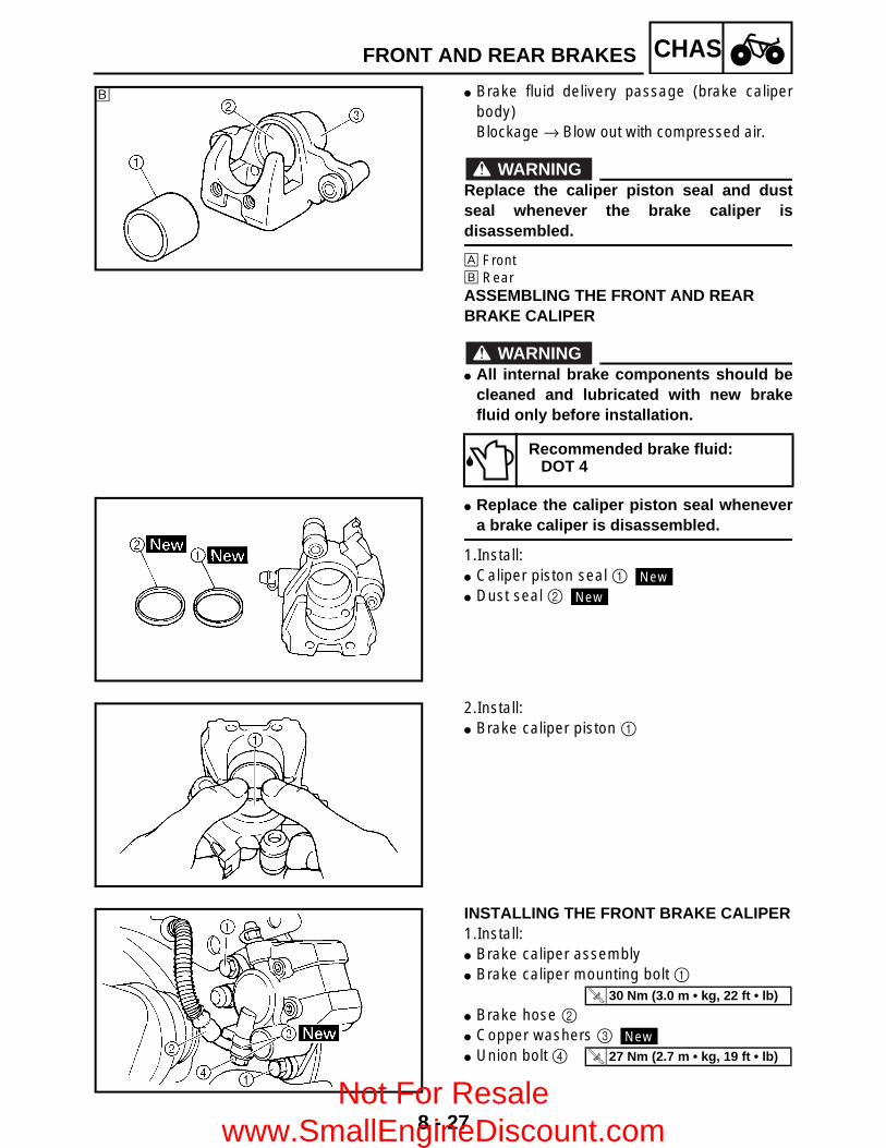
8 - 27
CHASFRONT AND REAR BRAKES
Brake fluid delivery passage (brake caliperbody)Blockage → Blow out with compressed air.
WARNINGReplace the caliper piston seal and dustseal whenever the brake caliper isdisassembled.
È FrontÉ RearASSEMBLING THE FRONT AND REAR BRAKE CALIPER
WARNING All internal brake components should be
cleaned and lubricated with new brakefluid only before installation.
Replace the caliper piston seal whenevera brake caliper is disassembled.
1.Install: Caliper piston seal 1 Dust seal 2
Recommended brake fluid:DOT 4
É
New
New
2.Install: Brake caliper piston 1
INSTALLING THE FRONT BRAKE CALIPER1.Install: Brake caliper assembly Brake caliper mounting bolt 1
Brake hose 2 Copper washers 3 Union bolt 4
T R..
30 Nm (3.0 m • kg, 22 ft • lb)
New
T R..
27 Nm (2.7 m • kg, 19 ft • lb)
Not For Resale www.SmallEngineDiscount.com

8 - 28
CHASFRONT AND REAR BRAKES
CAUTION:When installing the brake hose on thebrake caliper, make sure that the brakepipe touches the projection a on the brakecaliper.
WARNINGProper brake hose routing is essential toinsure safe motorcycle operation. Refer to“CABLE ROUTING” in CHAPTER 2.
2.Fill: Brake reservoir
CAUTION:Brake fluid may damage painted surfacesor plastic parts. Always clean up spilledbrake fluid immediately.
WARNING Use only the designated quality brake
fluid: other brake fluids may deterioratethe rubber seals, causing leakage andpoor brake performance.
Refill with the same type of brake fluid:mixing brake fluids may result in aharmful chemical reaction and lead topoor brake performance.
Be careful that water does not enter themaster cylinder when refilling. Water willsignificantly lower the boiling point of thebrake fluid and may result in vapor lock.
3.Air bleed Brake system
Refer to “BLEEDING THE HYDRAULICBRAKE SYSTEM” in CHAPTER 3.
4.Check: Brake fluid level
Brake fluid level is under the “LOWER” levelline → Fill up.Refer to “CHECKING THE BRAKE FLUIDLEVEL” in CHAPTER 3.
Recommended brake fluid:DOT 4
Not For Resale www.SmallEngineDiscount.com
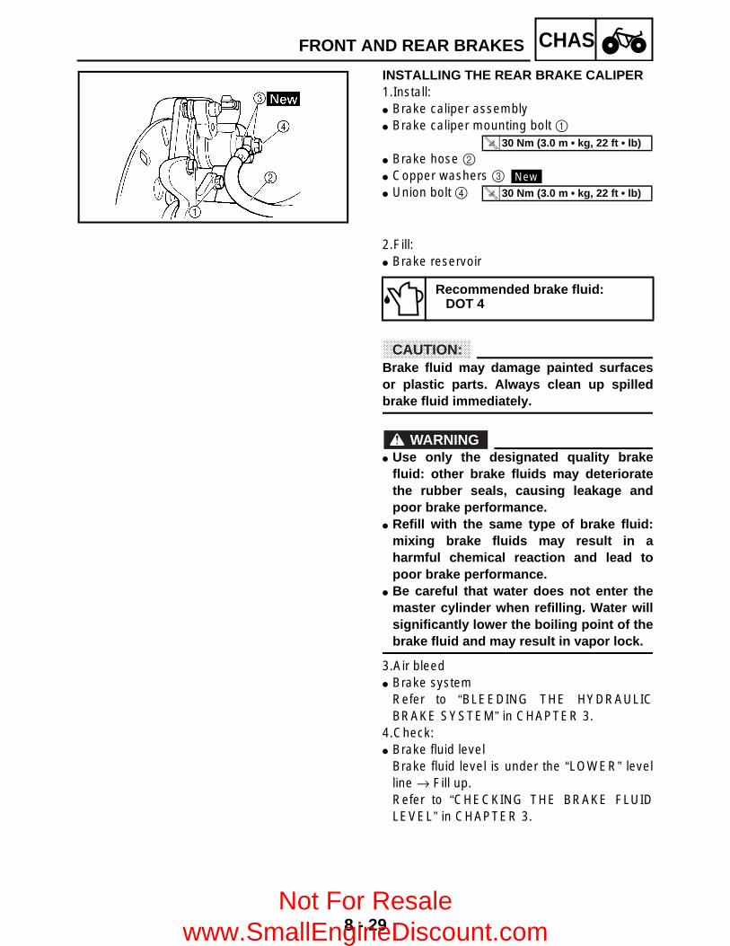
8 - 29
CHASFRONT AND REAR BRAKES
INSTALLING THE REAR BRAKE CALIPER1.Install: Brake caliper assembly Brake caliper mounting bolt 1
Brake hose 2 Copper washers 3 Union bolt 4
T R..
30 Nm (3.0 m • kg, 22 ft • lb)
New
T R..
30 Nm (3.0 m • kg, 22 ft • lb)
2.Fill: Brake reservoir
CAUTION:Brake fluid may damage painted surfacesor plastic parts. Always clean up spilledbrake fluid immediately.
WARNING Use only the designated quality brake
fluid: other brake fluids may deterioratethe rubber seals, causing leakage andpoor brake performance.
Refill with the same type of brake fluid:mixing brake fluids may result in aharmful chemical reaction and lead topoor brake performance.
Be careful that water does not enter themaster cylinder when refilling. Water willsignificantly lower the boiling point of thebrake fluid and may result in vapor lock.
3.Air bleed Brake system
Refer to “BLEEDING THE HYDRAULICBRAKE SYSTEM” in CHAPTER 3.
4.Check: Brake fluid level
Brake fluid level is under the “LOWER” levelline → Fill up.Refer to “CHECKING THE BRAKE FLUIDLEVEL” in CHAPTER 3.
Recommended brake fluid:DOT 4
Not For Resale www.SmallEngineDiscount.com
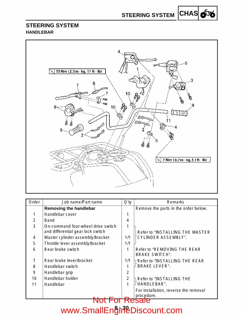
8 - 30
CHASSTEERING SYSTEM
STEERING SYSTEMHANDLEBAR
Order Job name/Part name Q’ty Remarks
Removing the handlebar Remove the parts in the order below.1 Handlebar cover 12 Band 43 On-command four-wheel drive switch
and differential gear lock switch1
Refer to “INSTALLING THE MASTER CYLINDER ASSEMBLY”.4 Master cylinder assembly/bracket 1/1
5 Throttle lever assembly/bracket 1/16 Rear brake switch 1 Refer to “REMOVING THE REAR
BRAKE SWITCH”.7 Rear brake lever/bracket 1/1 Refer to “INSTALLING THE REAR
BRAKE LEVER”.8 Handlebar switch 19 Handlebar grip 2
10 Handlebar holder 2 Refer to “INSTALLING THE HANDLEBAR”.11 Handlebar 1
For installation, reverse the removal procedure.
Not For Resale www.SmallEngineDiscount.com
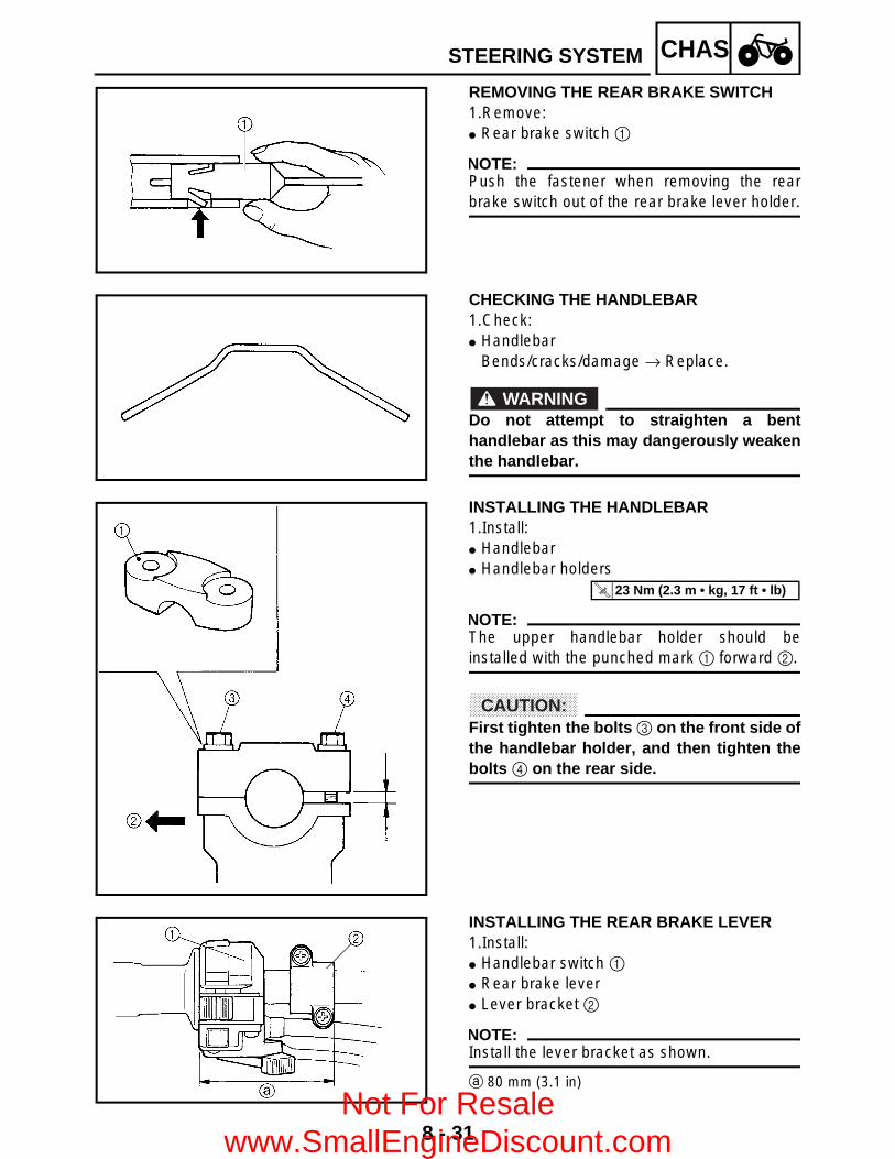
8 - 31
CHASSTEERING SYSTEM
REMOVING THE REAR BRAKE SWITCH1.Remove: Rear brake switch 1
NOTE:Push the fastener when removing the rearbrake switch out of the rear brake lever holder.
CHECKING THE HANDLEBAR1.Check: Handlebar
Bends/cracks/damage → Replace.
WARNINGDo not attempt to straighten a benthandlebar as this may dangerously weakenthe handlebar.
INSTALLING THE HANDLEBAR1.Install: Handlebar Handlebar holders
NOTE:The upper handlebar holder should beinstalled with the punched mark 1 forward 2.
CAUTION:First tighten the bolts 3 on the front side ofthe handlebar holder, and then tighten thebolts 4 on the rear side.
T R..
23 Nm (2.3 m • kg, 17 ft • lb)
INSTALLING THE REAR BRAKE LEVER1.Install: Handlebar switch 1 Rear brake lever Lever bracket 2
NOTE:Install the lever bracket as shown.
a 80 mm (3.1 in)
Not For Resale www.SmallEngineDiscount.com

8 - 32
CHASSTEERING SYSTEM
INSTALLING THE MASTER CYLINDER ASSEMBLY1.Install: Throttle lever assembly Master cylinder assembly
NOTE:The “UP” mark on the master cylinder bracketshould face up.
T R..
7 Nm (0.7 m • kg, 5.1 ft • lb)
Not For Resale www.SmallEngineDiscount.com

8 - 33
CHASSTEERING SYSTEM
STEERING STEM
Order Job name/Part name Q’ty Remarks
Removing the steering stem Remove the parts in the order below.Handlebar Refer to “HANDLEBAR”.Seat Refer to “SEAT, CARRIERS, FENDERS
AND FUEL TANK” in CHAPTER 3.Front fender1 Lock washer 1 Refer to “INSTALLING THE CABLE
GUIDE”.2 Cable guide 13 Steering stem bushing 24 Collar 25 Oil seal 26 Tie rod end nut 27 Tie rod 2 Disconnect.8 Steering stem nut 19 Pitman arm 1
10 Steering stem 1
Not For Resale www.SmallEngineDiscount.com

8 - 34
CHASSTEERING SYSTEM
Order Job name/Part name Q’ty Remarks
11 Oil seal 112 Bearing retainer 1 Refer to “REMOVING/INSTALLING THE
BEARING RETAINER”.13 Bearing 114 Oil seal 1
For installation, reverse the removal procedure.
Not For Resale www.SmallEngineDiscount.com

8 - 35
CHASSTEERING SYSTEM
REMOVING THE BEARING RETAINER1.Remove: Bearing retainer (steering stem)
Damper rod holder:P/N. YM-01327, 90890-01327
CHECKING THE STEERING STEM1.Check: Steering stem
Bends → Replace.
WARNINGDo not attempt to straighten a bent stem;this may dangerously weaken the stem.
2.Check: Oil seals 1 Steering stem bushings 2
Wear/damage → Replace.
INSTALLING THE BEARING RETAINER1.Install: Bearing retainer (steering stem)
INSTALLING THE CABLE GUIDE1.Install Cable guide Lock washer Bolts 2.Bend the lock washer tab along a flat side of
the bolt.
NOTE:Pass the cables and hoses through the cableguide. Refer to “CABLE ROUTING” inCHAPTER 2.
Damper rod holder:P/N. YM-01327, 90890-01327
T R..
40 Nm (4.0 m • kg, 29 ft • lb)
New
T R..
23 Nm (2.3 m • kg, 17 ft • lb)
Not For Resale www.SmallEngineDiscount.com
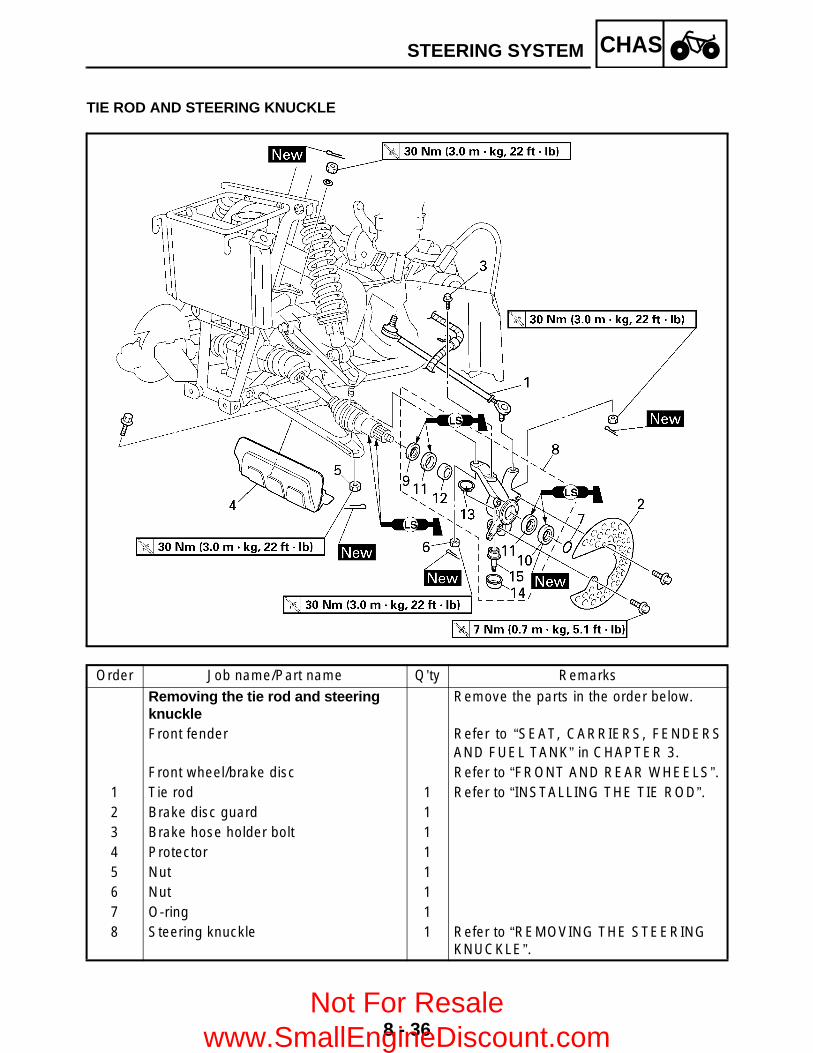
8 - 36
CHASSTEERING SYSTEM
TIE ROD AND STEERING KNUCKLE
Order Job name/Part name Q’ty Remarks
Removing the tie rod and steering knuckle
Remove the parts in the order below.
Front fender Refer to “SEAT, CARRIERS, FENDERSAND FUEL TANK” in CHAPTER 3.
Front wheel/brake disc Refer to “FRONT AND REAR WHEELS”.1 Tie rod 1 Refer to “INSTALLING THE TIE ROD”.2 Brake disc guard 13 Brake hose holder bolt 14 Protector 15 Nut 16 Nut 17 O-ring 18 Steering knuckle 1 Refer to “REMOVING THE STEERING
KNUCKLE”.
Not For Resale www.SmallEngineDiscount.com

8 - 37
CHASSTEERING SYSTEM
Order Job name/Part name Q’ty Remarks
9 Oil seal 110 Oil seal 111 Bearing 212 Spacer 113 Circlip 114 Rubber boot 115 Ball joint 1
For installation, reverse the removal procedure.
Not For Resale www.SmallEngineDiscount.com

8 - 38
CHASSTEERING SYSTEM
REMOVING THE STEERING KNUCKLE1.Remove: Steering knuckle 1
NOTE:Use a general puller to separate the ball joint2 and steering knuckle 1 or front lower arm3.
CHECKING THE TIE ROD1.Check: Tie rod free play and movement
Free play → Replace the tie rod end.Turns roughly → Replace the tie rod end.
2.Check: Tie rod Bends/damage → Replace.
CHECKING THE STEERING KNUCKLE1.Check: Steering knuckle
Damage/pitting → Replace.
2.Check: Ball joint
Damage/pitting → Replace the ball joint.Free play → Replace the ball joint.Turns roughly → Replace the ball joint.
*****************************************************Replacement steps: Clean the outside of the steering knuckle. Remove the steering knuckle oil seal. Remove the circlip 1 and rubber boot 2.
Use the ball joint remover and installer set.
Not For Resale www.SmallEngineDiscount.com

8 - 39
CHASSTEERING SYSTEM
Install the body 3, short bolt 5, removerwasher 6 and remover spacer 7 onto balljoint.
NOTE: Remover washer 6 must be aligned with the
projection on the head of the ball joint. Surface a of the remover spacer 7 must be
aligned with surface b of the steeringknuckle.
Hold the body 3 in place while turning in theshort bolt 5 to remove the ball joint A fromthe steering knuckle.
Remove the ball joint remover/installer.
Ball joint remover/installer set:P/N. YM-01474/90890-01474
Ball joint remover/installer attachment set:
P/N. YM-01477
3 BodyYM-0147490890-01474
4 Long boltYM-0147490890-01474
5 Short bolt YM-014776 Remover washer YM-014777 Remover spacer YM-014778 Installer attachment YM-014779 Installer spacer YM-014770 Installer guide YM-01477
Install the long bolt 4, installer spacer 9and installer guide 0 onto the body 3.
Not For Resale www.SmallEngineDiscount.com
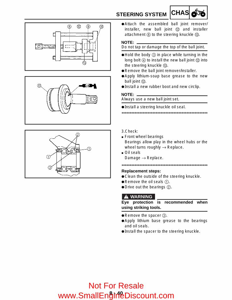
8 - 40
CHAS
Attach the assembled ball joint remover/installer, new ball joint B and installerattachment 8 to the steering knuckle C.
NOTE:Do not tap or damage the top of the ball joint.
Hold the body 3 in place while turning in thelong bolt 4 to install the new ball joint B intothe steering knuckle C.
Remove the ball joint remover/installer. Apply lithium-soap base grease to the new
ball joint B. Install a new rubber boot and new circlip.
NOTE:Always use a new ball joint set.
Install a steering knuckle oil seal.
*****************************************************
3.Check: Front wheel bearings
Bearings allow play in the wheel hubs or thewheel turns roughly → Replace.
Oil sealsDamage → Replace.
*****************************************************Replacement steps: Clean the outside of the steering knuckle. Remove the oil seals 1. Drive out the bearings 2.
WARNINGEye protection is recommended whenusing striking tools.
Remove the spacer 3. Apply lithium base grease to the bearings
and oil seals. Install the spacer to the steering knuckle.
STEERING SYSTEM
Not For Resale www.SmallEngineDiscount.com

8 - 41
CHAS
Install the new bearings.
NOTE:Install the outside bearing first.
CAUTION:Do not strike the center race or balls of thebearing. Contact should be made only withthe outer race.
Install a new oil seal.
NOTE:When installing the oil seals, the “seal side” ofthe oil seal faces out.
*****************************************************
INSTALLING THE TIE ROD1.Install: Tie rods (left and right)
NOTE:The tie rod which must be installed on the outside has grooves 1.
T R..
30 Nm (3.0 m • kg, 22 ft • lb)
2.Adjust: Toe-in
Refer to “ADJUSTING THE TOE-IN” inCHAPTER 3.
STEERING SYSTEM
Not For Resale www.SmallEngineDiscount.com
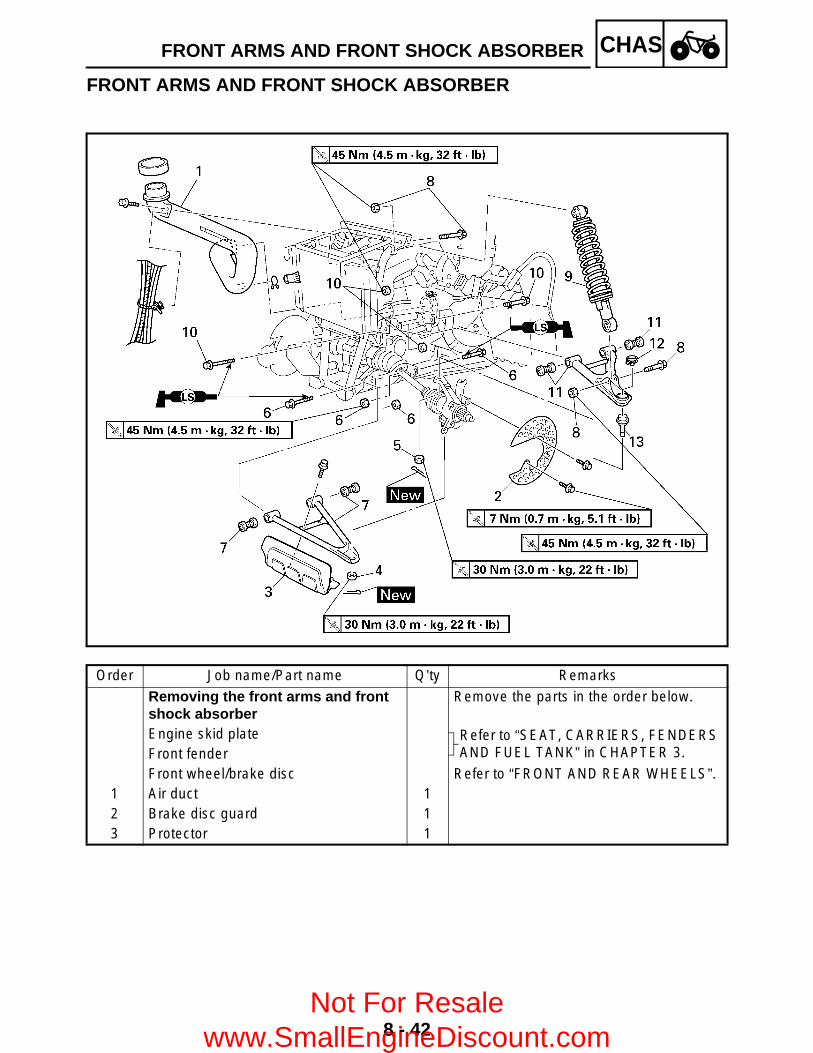
8 - 42
CHASFRONT ARMS AND FRONT SHOCK ABSORBER
FRONT ARMS AND FRONT SHOCK ABSORBER
Order Job name/Part name Q’ty Remarks
Removing the front arms and front shock absorber
Remove the parts in the order below.
Engine skid plate Refer to “SEAT, CARRIERS, FENDERS AND FUEL TANK” in CHAPTER 3.Front fender
Front wheel/brake disc Refer to “FRONT AND REAR WHEELS”.1 Air duct 12 Brake disc guard 13 Protector 1
Not For Resale www.SmallEngineDiscount.com

8 - 43
CHASFRONT ARMS AND FRONT SHOCK ABSORBER
Order Job name/Part name Q’ty Remarks
4 Nut 1
Refer to “REMOVING THE FRONT ARMS” and “INSTALLING THE FRONT ARMS AND FRONT SHOCK ABSORBER”.
5 Nut 16 Bolt/nut 2/27 Front lower arm/bushing 1/28 Nut/bolt 2/29 Front shock absorber 1
10 Bolt/nut 2/211 Front upper arm/bushing 1/212 Circlip 113 Ball joint 1
For installation, reverse the removal procedure.
Not For Resale www.SmallEngineDiscount.com
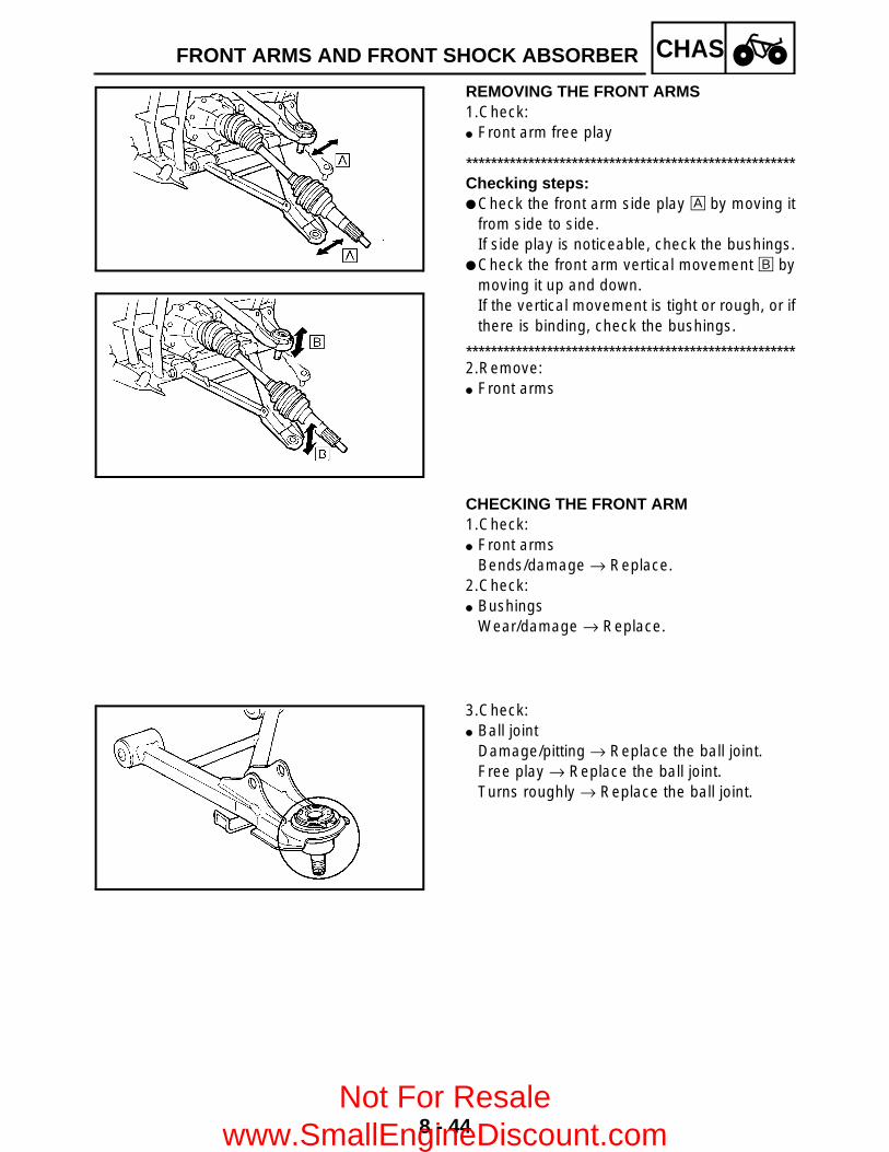
8 - 44
CHASFRONT ARMS AND FRONT SHOCK ABSORBER
REMOVING THE FRONT ARMS 1.Check: Front arm free play
*****************************************************Checking steps: Check the front arm side play È by moving it
from side to side.If side play is noticeable, check the bushings.
Check the front arm vertical movement É bymoving it up and down.If the vertical movement is tight or rough, or ifthere is binding, check the bushings.
*****************************************************2.Remove: Front arms
CHECKING THE FRONT ARM1.Check: Front arms
Bends/damage → Replace.2.Check: Bushings
Wear/damage → Replace.
3.Check: Ball joint
Damage/pitting → Replace the ball joint.Free play → Replace the ball joint.Turns roughly → Replace the ball joint.
Not For Resale www.SmallEngineDiscount.com

8 - 45
CHAS
*****************************************************Replacement steps: Clean the outside of the front lower arm. Remove the circlip 1 and rubber boot 2.
Use the ball joint remover and installer set.
Install the body 3, long bolt 4, removerwasher 5 and remover spacer 6 onto balljoint.
NOTE:Remover washer 5 must be aligned with theprojection on the head of the ball joint.
Hold the body 3 in place while turning in thelong bolt 4 to remove the ball joint 0 fromthe front lower arm.
Remove the ball joint remover/installer.
Ball joint remover/installer set:P/N. YM-01474/90890-01474
Ball joint remover/installer attachment set:
P/N. YM-01477
3 BodyYM-0147490890-01474
4 Long boltYM-0147490890-01474
5 Remover washer YM-014776 Remover spacer YM-014777 Installer attachment YM-014778 Installer spacer YM-014779 Installer guide YM-01477
Install the long bolt 4, installer spacer 8and installer guide 9 onto the body 3.
FRONT ARMS AND FRONT SHOCK ABSORBER
Not For Resale www.SmallEngineDiscount.com

8 - 46
CHASFRONT ARMS AND FRONT SHOCK ABSORBER
Attach the assembled ball joint remover/installer, new ball joint A and installerattachment 7 to the front lower arm B.
NOTE:Do not tap or damage the top of the ball joint.
Hold the body 3 in place while turning in thelong bolt 4 to install the new ball joint A intothe front lower arm B.
Remove the ball joint remover/installer. Apply lithium-soap base grease to the new
ball joint A. Install a new rubber boot and new circlip.
NOTE:Always use a new ball joint set.
*****************************************************
CHECKING THE FRONT SHOCK ABSORBER1.Check: Shock absorber rod
Bends/damage → Replace the shockabsorber assembly.
Shock absorber assemblyOil leaks → Replace the shock absorberassembly.
SpringFatigue → Replace the shock absorberassembly.Move the spring up and down.
Not For Resale www.SmallEngineDiscount.com

8 - 47
CHASFRONT ARMS AND FRONT SHOCK ABSORBER
INSTALLING THE FRONT ARMS AND FRONT SHOCK ABSORBER1.Install: Front arms Front shock absorber
*****************************************************Installation steps: Install the front upper arm 1 and front lower
arm 2.
NOTE: Lubricate the bolts 3 with lithium-soap-
based grease. Be sure to position the bolts 3 so that the
bolt head faces outward. Temporarily tighten the nuts 4.
Install the front shock absorber 5.
Install the ball joints.
Install the new cotter pins. Tighten the nuts 4.
NOTE:Before tightening the nuts 4, adjust the lengtha to 310 mm (12.2 in).
*****************************************************
T R..
Nut 6:45 Nm (4.5 m • kg, 32 ft • lb)
T R..
Nut 7:30 Nm (3.0 m • kg, 22 ft • lb)
T R..
Nut 4:45 Nm (4.5 m • kg, 32 ft • lb)
Not For Resale www.SmallEngineDiscount.com

8 - 48
CHASREAR SHOCK ABSORBER AND SWINGARM
REAR SHOCK ABSORBER AND SWINGARM
Order Job name/Part name Q’ty Remarks
Removing the rear shock absorber and swingarm
Remove the parts in the order below.
Rear wheel hubs/brake disc Refer to “FRONT AND REAR WHEELS”.Rear brake caliper/brake hose Refer to “FRONT AND REAR BRAKES”.Final drive gear assembly Refer to “REAR AXLE/FINAL DRIVE GEAR
AND DRIVE SHAFT” in CHAPTER 7.1 Clip/washer/pin 1/1/12 Nut/bolt 1/13 Rear shock absorber 14 Collar 15 Trailer hitch bracket 16 Final drive gear case breather hose 17 Metal clamp 1
Not For Resale www.SmallEngineDiscount.com

8 - 49
CHASREAR SHOCK ABSORBER AND SWINGARM
Order Job name/Part name Q’ty Remarks
8 Rear axle housing 1 Refer to “INSTALLING THE REAR AXLE HOUSING”.
9 Nut/bolt 2/2 Refer to “REMOVING THE SWINGARM”.10 Swingarm/bushing 1/2
11 Spring/rubber boot 1/1For installation, reverse the removal procedure.
Not For Resale www.SmallEngineDiscount.com

8 - 50
CHASREAR SHOCK ABSORBER AND SWINGARM
REMOVING THE SWINGARM 1.Check: Swingarm free play
*****************************************************Checking steps: Check the tightening torque of the nuts
(swingarm).
Check the swingarm side play È by movingit from side to side.If side play is noticeable, check the bushingand frame pivot.
Check the swingarm vertical movement Éby moving it up and down.If vertical movement is tight or rough, or ifthere is binding, check the bushing andframe pivot.
*****************************************************2.Remove: Nuts Bolts Swingarm
T R..
Nut (swingarm):82 Nm (8.2 m • kg, 59 ft • lb)
CHECKING THE REAR SHOCK ABSORBER1.Check: Shock absorber
Oil leaks → Replace the shock absorberassembly.
Shock absorber rodBends/damage → Replace the shockabsorber assembly.
SpringFatigue → Replace the shock absorberassembly.Move the spring up and down.
Not For Resale www.SmallEngineDiscount.com

8 - 51
CHASREAR SHOCK ABSORBER AND SWINGARM
CHECKING THE SWINGARM1.Check: Swingarm 1 Rear axle housing 2
Bends/cracks/damage → Replace.
2.Check: Bushings 1
Wear/damage → Replace.
CHECKING THE RUBBER BOOT1.Check: Rubber boot 1
Damage → Replace.
INSTALLING THE RUBBER BOOT1.Apply: Adhesive (for rubber)
(to the engine 1)2.Install: Rubber boot 2
NOTE:Be sure to position the rubber boot so that thetang 3 faces towards the left.
Not For Resale www.SmallEngineDiscount.com

8 - 52
CHASREAR SHOCK ABSORBER AND SWINGARM
INSTALLING THE REAR AXLE HOUSING1.Install: Rear axle housing Final gear case assembly Rear axle
(with dust seal)
*****************************************************Installation steps: Install the drive shaft.
Refer to “REAR AXLE/FINAL DRIVE GEARAND DRIVE SHAFT” in CHAPTER 7.
Apply sealant (Quick Gasket®) to the matingsurfaces of the swingarm and the final gearcase.
Temporarily install the rear axle housing 1and final gear case assembly 2 on theswingarm. The bolts and nuts 3 ~ 5 shouldbe temporarily tightened.
Install the rear axle (with dust seal) 6 fromthe left side of the machine.Refer to “REAR AXLE/FINAL DRIVE GEARAND DRIVE SHAFT” in CHAPTER 7.
Tighten the bolts and nuts 3 ~ 5 in thespecified order.
3 Nut (×4)4 Bolt (×4)5 Bolt/nut (×4)
*****************************************************
T R..
Nut 3:63 Nm (6.3 m • kg, 45 ft • lb)LOCTITE®
Bolt 4:63 Nm (6.3 m • kg, 45 ft • lb)LOCTITE®
Nut 5:63 Nm (6.3 m • kg, 45 ft • lb)
Not For Resale www.SmallEngineDiscount.com

9 - 1
– +ELECELECTRICAL COMPONENTSEB800000
ELECTRICALELECTRICAL COMPONENTS1 Main switch2 Front brake light
switch3 Rear brake switch4 Thermo switch 15 Battery6 Tail/brake light7 Fuse box
8 Four-wheel drive relay 2
9 Four-wheel drive relay 1
0 Main fuseA Starter relayB CDI unitC Rectifier/regulator
D Reverse switchE Neutral switchF High-range switchG Low-range switchH Speed sensorI Rear brake light switchJ Gear motorK Thermo switch 2
L FanM HeadlightN Circuit breaker (fan)O Four-wheel drive relay 3P Ignition coil
12 3
4 5
6
7
89
0
A B
C
GF
ED
HIJK
L
M
N
O
P
9
Not For Resale www.SmallEngineDiscount.com

9 - 2
– +ELECCHECKING THE SWITCH
CHECKING THE SWITCHCHECKING THE SWITCHUse a pocket tester to check the terminals forcontinuity. If the continuity is faulty at anypoint, replace the switch.
NOTE: Set the pocket tester to “0” before starting
the test. The pocket tester should be set to the “Ω × 1”
range when testing the switch for continuity. Turn the switch on and off a few times when
checking it.
Pocket tester: P/N. YU-03112, 90890-03112
CHECKING A SWITCH SHOWN IN THE MANUALThe terminal connections for switches (mainswitch, handlebar switch, engine stop switch,light switch, etc.) are shown in a chart similarto the one on the left.This chart shows the switch positions in thecolumn and the switch lead colors in the toprow.For each switch position, “ ” indicatesthe terminals with continuity.The example chart shows that:There is continuity between red and brown/blue, and between red and brown when theswitch is set to “ON”.
Br/L BrRR
R
R
Br
Br/L
ON
OFF
Not For Resale www.SmallEngineDiscount.com

9 - 3
– +ELECCHECKING THE SWITCH
Not For Resale www.SmallEngineDiscount.com
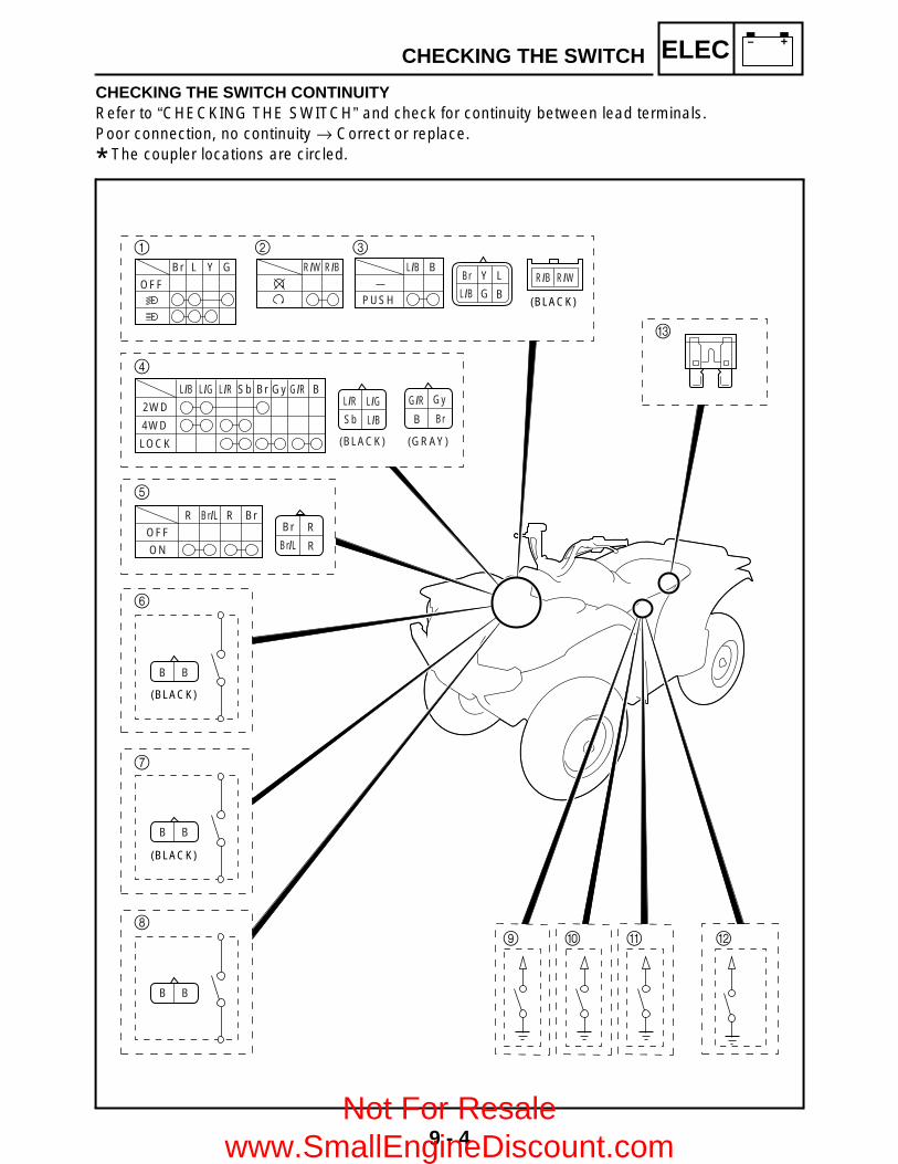
9 - 4
– +ELECCHECKING THE SWITCH
CHECKING THE SWITCH CONTINUITYRefer to “CHECKING THE SWITCH” and check for continuity between lead terminals.Poor connection, no continuity → Correct or replace.
* The coupler locations are circled.
L
B
Y
G
Br
L/B(BLACK)
1
4
5
C
6
2 3
R/B R/W
PUSH
Br L Y G BR/W
L/B L/G
Br/L BrR
L/R Sb Br Gy G/R B
R/B L/B
2WD
4WD
LOCK
L/G
L/B
L/R
Sb
Gy
Br
G/R
B
(BLACK) (GRAY)
ON
OFF
R BrBr/L
B B
(BLACK)
7
BB
(BLACK)
8B
BB
A09
Br/L BrRR
ON
OFF R
R
Br
Br/L
OFF
Not For Resale www.SmallEngineDiscount.com

9 - 5
– +ELECCHECKING THE SWITCH
1 Light switch2 Engine stop switch3 Start switch4 On-command four-wheel drive switch and differential gear lock switch5 Main switch6 Rear brake light switch7 Front brake light switch8 Rear brake switch9 Reverse switch0 Neutral switchA High-range switchB Low-range switchC Fuse
Not For Resale www.SmallEngineDiscount.com
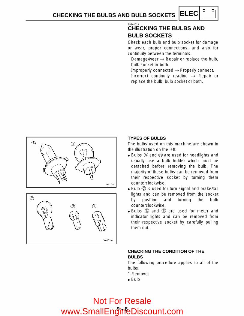
9 - 6
– +ELECCHECKING THE BULBS AND BULB SOCKETSEB801020
CHECKING THE BULBS AND BULB SOCKETSCheck each bulb and bulb socket for damageor wear, proper connections, and also forcontinuity between the terminals.
Damage/wear → Repair or replace the bulb,bulb socket or both.Improperly connected → Properly connect.Incorrect continuity reading → Repair orreplace the bulb, bulb socket or both.
TYPES OF BULBSThe bulbs used on this machine are shown inthe illustration on the left. Bulbs A and B are used for headlights and
usually use a bulb holder which must bedetached before removing the bulb. Themajority of these bulbs can be removed fromtheir respective socket by turning themcounterclockwise.
Bulb C is used for turn signal and brake/taillights and can be removed from the socketby pushing and turning the bulbcounterclockwise.
Bulbs D and E are used for meter andindicator lights and can be removed fromtheir respective socket by carefully pullingthem out.
CHECKING THE CONDITION OF THE BULBSThe following procedure applies to all of thebulbs.1.Remove: Bulb
Not For Resale www.SmallEngineDiscount.com
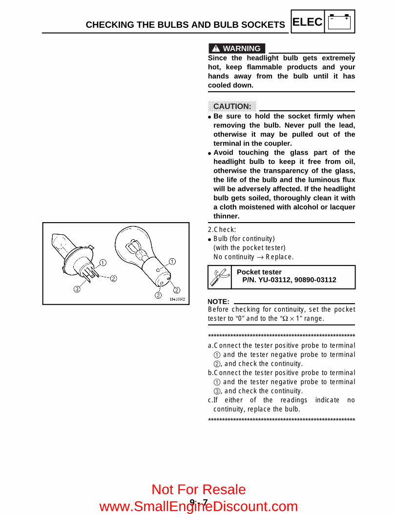
9 - 7
– +ELECCHECKING THE BULBS AND BULB SOCKETS
WARNINGSince the headlight bulb gets extremelyhot, keep flammable products and yourhands away from the bulb until it hascooled down.
CAUTION: Be sure to hold the socket firmly when
removing the bulb. Never pull the lead,otherwise it may be pulled out of theterminal in the coupler.
Avoid touching the glass part of theheadlight bulb to keep it free from oil,otherwise the transparency of the glass,the life of the bulb and the luminous fluxwill be adversely affected. If the headlightbulb gets soiled, thoroughly clean it witha cloth moistened with alcohol or lacquerthinner.
2.Check: Bulb (for continuity)
(with the pocket tester)No continuity → Replace.
NOTE:Before checking for continuity, set the pockettester to “0” and to the “Ω × 1” range.
*****************************************************a.Connect the tester positive probe to terminal1 and the tester negative probe to terminal2, and check the continuity.
b.Connect the tester positive probe to terminal1 and the tester negative probe to terminal3, and check the continuity.
c.If either of the readings indicate nocontinuity, replace the bulb.
*****************************************************
Pocket testerP/N. YU-03112, 90890-03112
Not For Resale www.SmallEngineDiscount.com

9 - 8
– +ELEC
CHECKING THE CONDITION OF THE BULB SOCKETSThe following procedure applies to all of thebulb sockets.1.Check: Bulb socket (for continuity)
(with the pocket tester)No continuity → Replace.
NOTE:Check each bulb socket for continuity in thesame manner as described in the bulb section;however, note the following.
*****************************************************a.Install a good bulb into the bulb socket.b.Connect the pocket tester probes to the
respective leads of the bulb socket.c.Check the bulb socket for continuity. If any of
the readings indicate no continuity, replacethe bulb socket.
*****************************************************
Pocket tester:P/N. YU-03112, 90890-03112
CHECKING THE BULBS AND BULB SOCKETS
Not For Resale www.SmallEngineDiscount.com
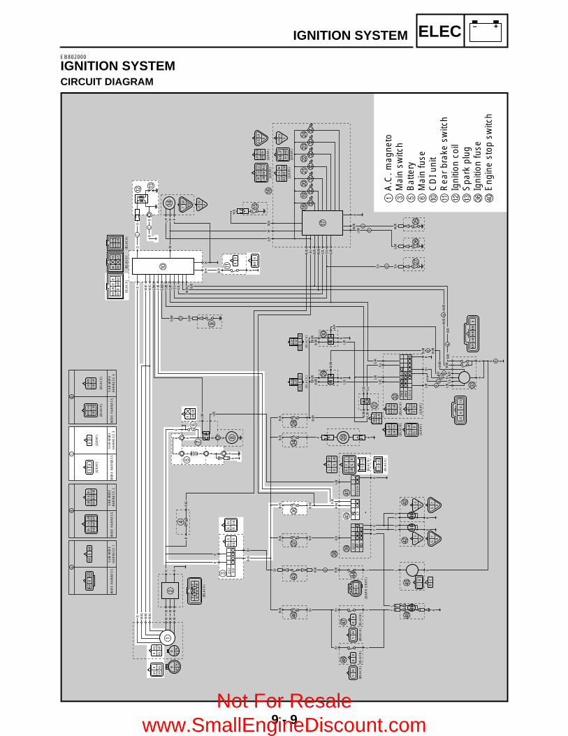
9 - 9
– +ELECIGNITION SYSTEMEB802000
IGNITION SYSTEMCIRCUIT DIAGRAM
W/B
BB/
RB/
RB
W/B
C
D
OB
BO
LB
BL
YB
rB
B
B/Y
B
BB
(GR
AY)
(GR
AY)
D
WIR
E H
AR
NE
SS
SU
B-W
IRE
H
AR
NE
SS
4
Br
Sb
L/B
R/B
Br/B
B/Y
L/B
Sb
Br
B/Y
Br/B
R/B
Br
YL
L/B
GB
LY
R/Y
BG
L/B
WS
bG
/L
L/W
B/R
W/L
G/L
Sb
W
W/L
B/R
L/W
W/R
Sb
L/WG/
W
Sb
W/R
G/W
L/W
W/B
L/Y
Br
W/R
L/Y
W/B
W/R
Br
W/G
R
W/R
W/G
RW/
G
W/L
W/R
RB
r
RBr
/L
Br
R
Br/L
R
L/G
L/R
L/B
Sb
L/R
L/G
Sb
L/B
R L/W
L/B
R/B
L/WO
B
B/Y
RW
/RW
/G
WY/
B
B/R
G/L
G/W
W/B
Sb
G/R
(BLA
CK
)
(BLA
CK
)(B
LAC
K)
C
WIR
E H
AR
NE
SS
SU
B-W
IRE
H
AR
NE
SS
3
B
WIR
E H
AR
NE
SS
SU
B-W
IRE
H
AR
NE
SS
2
A
WIR
E H
AR
NE
SS
SU
B-W
IRE
H
AR
NE
SS
1
(BLA
CK
)
(BLA
CK
)
(BLA
CK
)
(GR
AY)
(GR
AY)
(GR
AY)
(GR
AY)
(BLA
CK
)(B
LAC
K)
Gy
G/R
Br
B
G/R
Gy
BB
r
(GR
AY)
(GR
AY)
WW
WW
WW
OF
FO
N
OF
F
2WD
4WD
LOC
K
W/G
Br/
L
R/G
L/B
G/W
G/W
L/W
Br
Br
W/R
W/GR
W/G
W/R
L/W
L/Y
R/B
G/W
Y/B
G/R Sb
G/L
W/B B
/R
B/Y
B/Y
L/Y
R/G
Br/
RB
/RW
/BG
/L
G/R
W/L
W/L
R
Br
Sb
O
CB
O
B WW
B
B
B
W
B
W W W
W W W
R
RR
R
B
WW
WR
B
BP
US
H
_
R R B BB B
BB
R R
R
D
W/R
W/R
DL/W
B/R
B/R
L/W
D
A
Br/
B
Br/
B
Br/
B
B
B
W/B
W/B
W/B
A
Sb
Sb
O/R
P B/W
L/Y
W
B
G/R
R/G B
G/R
R/G
B
YG
B
YG
B
YG
B
B/Y
Br/R
Br/R
L/R
B
(BLA
CK
)
Br/B
Br/R
Br/R
L/G
B
(BLA
CK
)
Br/
R
L/R
B/Y
Br/
R
B
Br/
R
L/G
Br/
B
B
B B B
B
Br
Sb
L/BL/
G
Br B
/YS
bL/
B
B/Y
L/R
Y/B
Br/
RL/
R
Gy
Gy
G/R
Br/B
W/B
BB
/YB
/R
BL/
BS
bB
r
BB
BB
A
Y/B
Gy
Br/R
L/R
Br/
L
Br/
R
Br/
L
L/B
R/B
Br/
L
R/W
R/W
Br/
L
R/Y
Br/
L
Br
R/B
R/B
R/Y
P B
B
B
GY
GY
BL
L
L(B
LAC
K)
(BLA
CK
)
R/B
R/WR/B
R/W
B
GY
B
LY
YG
B
(DA
RK
GR
AY
)
(BLA
CK
)(B
LAC
K)
LR
/B
Br Y
YB
rB
B
(BLA
CK
)(B
LAC
K)
Br Y
12
3
45
67
8
9
0 A
B
C
D E
F
G
HIJKLM
OP
Q
R
ST
U
V
W
Y
\
]
b
d
ei
gh
b
^a
XZ
[c
f
N
1A
.C. m
agne
to3
Mai
n sw
itch
5B
atte
ry6
Mai
n fu
se0
CD
I uni
tA
Rea
r br
ake
switc
hB
Igni
tion
coil
CS
park
plu
gZ
Igni
tion
fuse
^E
ngin
e st
op s
witc
h
Not For Resale www.SmallEngineDiscount.com

9 - 10
– +ELECIGNITION SYSTEMEB802010
TROUBLESHOOTING
ProcedureCheck:1.Fuse (main, ignition)2.Battery3.Spark plug4.Ignition spark gap5.Spark plug cap resistance6.Ignition coil resistance
IF THE IGNITION SYSTEM FAILS TO OPERATE (NO SPARK OR INTERMITTENT SPARK):
7.Engine stop switch8.Main switch9.Pickup coil resistance
10.Charging/rotor rotation direction detection coil resistance
11.Wiring connection (the entire ignition system)
NOTE: Remove the following part(s) before
troubleshooting:1)Seat2)Fuel tank side panels3)Front carrier4)Front fender Use the following special tool(s) for
troubleshooting.
Dynamic spark tester:P/N. YM-34487
Ignition checker: P/N. 90890-06754
Pocket tester:P/N. YU-03112, 90890-03112
EB802011
CONTINUITY
1.Fuse (main, ignition)
Refer to “CHECKING THE SWITCH”.
NO CONTINUITY
Replace the fuse.
EB802012
CORRECT
2.Battery
Check the battery condition.Refer to “CHECKING THE BATTERY” in CHAPTER 3.
Open-circuit voltage:12.8 V or more at 20 °C (68 °F)
INCORRECT
Clean the battery terminals. Recharge or replace the battery.
3.Spark plug
Check the spark plug condition. Check the spark plug type. Check the spark plug gap.
Refer to “CHECKING THE SPARK PLUG”in CHAPTER 3.
Standard spark plug:DR8EA/NGK
Not For Resale www.SmallEngineDiscount.com

9 - 11
– +ELECIGNITION SYSTEM
CORRECT
Spark plug gap:0.6 ~ 0.7 mm (0.024 ~ 0.028 in)
INCORRECT
Repair or replace the spark plug.
OUT OFSPECIFICATION OR NO SPARK
4.Ignition spark gap
Disconnect the spark plug cap from thespark plug.
Connect the dynamic spark tester 1 asshown.
2 Spark plug cap3 Spark plug Turn the main switch to “ON”. Check the ignition spark gap. Crank the engine by pushing the starter
switch, and increase the spark gap until amisfiring occurs.
Minimum spark gap:6.0 mm (0.24 in)
MEETS SPECIFICATION
The ignition system is not faulty.
5.Spark plug cap resistance
Remove the spark plug cap. Connect the pocket tester (Ω × 1k) to the
spark plug cap.
MEETSSPECIFICATION
Check that the spark plug cap has thespecified resistance.
Spark plug cap resistance:10 kΩ at 20 °C (68 °F)
*
OUT OF SPECIFICATION
Replace the spark plug cap.
Not For Resale www.SmallEngineDiscount.com

9 - 12
– +ELECIGNITION SYSTEM
C0NTINUITY
6.Ignition coil resistance
Disconnect the ignition coil connector fromthe wire harness.
Connect the pocket tester (Ω × 1) to theignition coil.
Tester (+) lead → Orange lead terminalTester (–) lead → Ignition coil base
Check that the primary coil has thespecified resistance.
Primary coil resistance: 0.18 ~ 0.28 Ω at 20 °C (68 °F)
*
BOTH MEETSPECIFICATION
Connect the pocket tester (Ω × 1k) to theignition coil.
Tester (+) lead → Orange lead terminalTester (–) lead → Spark plug lead
Check that the secondary coil has thespecified resistance.
Secondary coil resistance:6.32 ~ 9.48 kΩ at 20 °C (68 °F) OUT OF SPECIFICATION
Replace the ignition coil.
CORRECT
7.Engine stop switch
Refer to “CHECKING THE SWITCH”.
*
INCORRECT
Replace the handlebar switch (left).
Not For Resale www.SmallEngineDiscount.com

9 - 13
– +ELECIGNITION SYSTEM
C0NTINUITY
CORRECT
8.Main switch
Refer to “CHECKING THE SWITCH”.
*
INCORRECT
Replace the main switch.
9.Pickup coil resistance
Disconnect the AC magneto coupler fromthe wire harness.
Connect the pocket tester (Ω × 100) to thepickup coil terminal.
Tester (+) lead → White/Red terminal 1 Tester (–) lead → White/Green terminal 2
MEETSSPECIFICATION
Check the pickup coil for the specifiedresistance.
Pickup coil resistance:459 ~ 561 Ω at 20 °C (68 °F)(White/Red – White/Green)
OUT OF SPECIFICATION
Replace the pickup coil/stator assembly.
10.Charging/rotor rotation direction detectioncoil resistance
Disconnect the AC magneto coupler fromthe wire harness.
Connect the pocket tester (Ω × 100) to thecharging/rotor rotation direction detectioncoil terminal.
Tester (+) lead → Red terminal 1 Tester (–) lead → White/Blue terminal 2
MEETSSPECIFICATION
Check the charging/rotor rotation directiondetection coil for the specified resistance.
Rotor rotation direction sensing coil resistance:
0.085 ~ 0.105 Ω at 20 °C (68 °F)(Red – White/Blue)
*
OUT OF SPECIFICATION
Replace the pickup coil/stator assembly.
Not For Resale www.SmallEngineDiscount.com
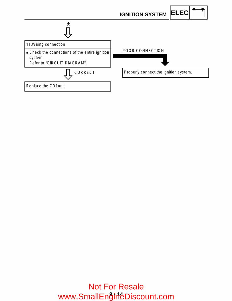
9 - 14
– +ELECIGNITION SYSTEM
C0NTINUITY
CORRECT
11.Wiring connection
Check the connections of the entire ignitionsystem.Refer to “CIRCUIT DIAGRAM”.
Replace the CDI unit.
*
POOR CONNECTION
Properly connect the ignition system.
Not For Resale www.SmallEngineDiscount.com

9 - 15
– +ELECELECTRIC STARTING SYSTEMEB803000
ELECTRIC STARTING SYSTEMCIRCUIT DIAGRAM
W/B
BB/
RB/
RB
W/B
C
D
OB
BO
LB
BL
YB
rB
B
B/Y
B
BB
(GR
AY)
(GR
AY)
D
WIR
E H
AR
NE
SS
SU
B-W
IRE
H
AR
NE
SS
4
Br
Sb
L/B
R/B
Br/B
B/Y
L/B
Sb
Br
B/Y
Br/B
R/B
Br
YL
L/B
GB
LY
R/Y
BG
L/B
WS
bG
/L
L/W
B/R
W/L
G/L
Sb
W
W/L
B/R
L/W
W/R
Sb
L/WG/
W
Sb
W/R
G/W
L/W
W/B
L/Y
Br
W/R
L/Y
W/B
W/R
Br
W/G
R
W/R
W/G
RW/
G
W/L
W/R
RB
r
RBr
/L
Br
R
Br/L
R
L/G
L/R
L/B
Sb
L/R
L/G
Sb
L/B
R L/W
L/B
R/B
L/WO
B
B/Y
RW
/RW
/G
WY/
B
B/R
G/L
G/W
W/B
Sb
G/R
(BLA
CK
)
(BLA
CK
)(B
LAC
K)
C
WIR
E H
AR
NE
SS
SU
B-W
IRE
H
AR
NE
SS
3
B
WIR
E H
AR
NE
SS
SU
B-W
IRE
H
AR
NE
SS
2
A
WIR
E H
AR
NE
SS
SU
B-W
IRE
H
AR
NE
SS
1
(BLA
CK
)
(BLA
CK
)
(BLA
CK
)
(GR
AY)
(GR
AY)
(GR
AY)
(GR
AY)
(BLA
CK
)(B
LAC
K)
Gy
G/R
Br
B
G/R
Gy
BB
r
(GR
AY)
(GR
AY)
WW
WW
WW
OF
FO
N
OF
F
2WD
4WD
LOC
K
W/G
Br/
L
R/G
L/B
G/W
G/W
L/W
Br
Br
W/R
W/GR
W/G
W/R
L/W
L/Y
R/B
G/W
Y/B
G/R Sb
G/L
W/B B
/R
B/Y
B/Y
L/Y
R/G
Br/
RB
/RW
/BG
/L
G/R
W/L
W/L
R
Br
Sb
O
CB
O
B WW
B
B
B
W
B
W W W
W W W
R
RR
R
B
WW
WR
B
BP
US
H
_
R R B BB B
BB
R R
R
D
W/R
W/R
DL/W
B/R
B/R
L/W
D
A
Br/
B
Br/
B
Br/
B
B
B
W/B
W/B
W/B
A
Sb
Sb
O/R
P B/W
L/Y
W
B
G/R
R/G B
G/R
R/G
B
YG
B
YG
B
YG
B
B/Y
Br/R
Br/R
L/R
B
(BLA
CK
)
Br/B
Br/R
Br/R
L/G
B
(BLA
CK
)
Br/
R
L/R
B/Y
Br/
R
B
Br/
R
L/G
Br/
B
B
B B B
B
Br
Sb
L/BL/
G
Br B
/YS
bL/
B
B/Y
L/R
Y/B
Br/
RL/
R
Gy
Gy
G/R
Br/B
W/B
BB
/YB
/R
BL/
BS
bB
r
BB
BB
A
Y/B
Gy
Br/R
L/R
Br/
L
Br/
R
Br/
L
L/B
R/B
Br/
L
R/W
R/W
Br/
L
R/Y
Br/
L
Br
R/B
R/B
R/Y
P B
B
B
GY
GY
BL
L
L(B
LAC
K)
(BLA
CK
)
R/B
R/WR/B
R/W
B
GY
B
LY
YG
B
(DA
RK
GR
AY
)
(BLA
CK
)(B
LAC
K)
LR
/B
Br Y
YB
rB
B
(BLA
CK
)(B
LAC
K)
Br Y
12
3
45
67
8
9
0 A
B
C
D E
F
G
HIJKLM
OP
Q
R
ST
U
V
W
Y
\
]
b
d
ei
gh
b
^a
XZ
[c
f
N
3M
ain
switc
h5
Bat
tery
6M
ain
fuse
7S
tart
er r
elay
8S
tart
er m
otor
0C
DI u
nit
ZIg
nitio
n fu
se^
Eng
ine
stop
sw
itch
aS
tart
sw
itch
Not For Resale www.SmallEngineDiscount.com

9 - 16
– +ELECELECTRIC STARTING SYSTEMEB803020
TROUBLESHOOTING
ProcedureCheck:1.Fuse (main, ignition)2.Battery3.Starter motor4.Starter relay5.Main switch
IF THE STARTER MOTOR FAILS TO OPERATE:
6.Engine stop switch7.Start switch8. Wiring connection (the entire starting
system)
NOTE: Remove the following part(s) before
troubleshooting:1)Seat2)Fuel tank side panels3)Fuel tank4)Air cleaner case5)Front carrier6)Front fender panel Use the following special tool(s) for
troubleshooting.
Pocket tester:P/N. YU-03112, 90890-03112
EB802011
CONTINUITY
1.Fuse (main, ignition)
Refer to “CHECKING THE SWITCH”.
NO CONTINUITY
Replace the fuse.
EB802012
CORRECT
2.Battery
Check the battery condition.Refer to “CHECKING THE BATTERY” in CHAPTER 3.
Open-circuit voltage:12.8 V or more at 20 °C (68 °F)
*
INCORRECT
Clean the battery terminals. Recharge or replace the battery.
Not For Resale www.SmallEngineDiscount.com
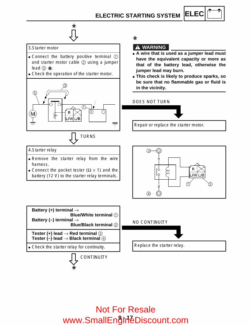
9 - 17
– +ELECELECTRIC STARTING SYSTEM
C0NTINUITY
TURNS
3.Starter motor
Connect the battery positive terminal 1and starter motor cable 2 using a jumperlead 3 .
Check the operation of the starter motor.
*
*
WARNING A wire that is used as a jumper lead must
have the equivalent capacity or more asthat of the battery lead, otherwise thejumper lead may burn.
This check is likely to produce sparks, sobe sure that no flammable gas or fluid isin the vicinity.
*
DOES NOT TURN
Repair or replace the starter motor.
4.Starter relay
Remove the starter relay from the wireharness.
Connect the pocket tester (Ω × 1) and thebattery (12 V) to the starter relay terminals.
CONTINUITY
Battery (+) terminal → Blue/White terminal 1
Battery (–) terminal → Blue/Black terminal 2
Tester (+) lead → Red terminal 3 Tester (–) lead → Black terminal 4
Check the starter relay for continuity.
*
NO CONTINUITY
Replace the starter relay.
Not For Resale www.SmallEngineDiscount.com

9 - 18
– +ELECELECTRIC STARTING SYSTEM
C0NTINUITY
CORRECT
5.Main switch
Refer to “CHECKING THE SWITCH”.
*
INCORRECT
Replace the main switch.
CORRECT
6.Engine stop switch
Refer to “CHECKING THE SWITCH”.
INCORRECT
Replace the handlebar switch (left).
CORRECT
7.Start switch
Refer to “CHECKING THE SWITCH”.
INCORRECT
Replace the handlebar switch (left).
EB803028
8.Wiring connection
Check the connections of the entire startingsystem.Refer to “CIRCUIT DIAGRAM”.
POOR CONNECTION
Properly connect the starting system.
Not For Resale www.SmallEngineDiscount.com
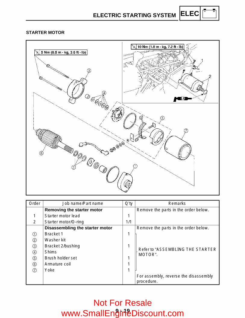
9 - 19
– +ELECELECTRIC STARTING SYSTEM
STARTER MOTOR
Order Job name/Part name Q’ty Remarks
Removing the starter motor Remove the parts in the order below.1 Starter motor lead 12 Starter motor/O-ring 1/1
Disassembling the starter motor Remove the parts in the order below.1 Bracket 1 1
Refer to “ASSEMBLING THE STARTER MOTOR”.
2 Washer kit3 Bracket 2/bushing 14 Shims5 Brush holder set 16 Armature coil 17 Yoke 1
For assembly, reverse the disassembly procedure.
Not For Resale www.SmallEngineDiscount.com

9 - 20
– +ELECELECTRIC STARTING SYSTEM
CHECKING THE STARTER MOTOR1.Check: Commutator
Dirty → Clean it with #600 grit sandpaper.2.Measure: Commutator diameter a
Out of specification → Replace the startermotor.
3.Measure: Mica undercut b
Out of specification → Scrape the mica usinga hacksaw blade.
NOTE:Scrape the mica to the proper measurementusing a hacksaw blade which has beengrounded to fit the commutator.
Outside diameter:28 mm (1.10 in)
<Wear limit:>27 mm (1.06 in)
Mica undercut:0.7 mm (0.03 in)
4.Check: Armature coil (insulation/continuity)
Defects → Replace the starter motor.
*****************************************************Checking steps: Connect the pocket tester for the continuity
check 1 and insulation check 2. Measure the armature resistances.
If the resistance is incorrect, replace thestarter motor.
*****************************************************
Armature coil resistance:Continuity check 1:
0.025 ~ 0.035 Ω at 20 °C (68 °F)Insulation check 2:
More than 1 MΩ at 20 °C (68 °F)
Not For Resale www.SmallEngineDiscount.com
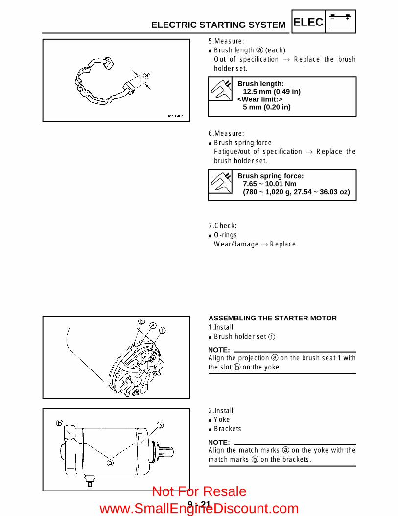
9 - 21
– +ELECELECTRIC STARTING SYSTEM
5.Measure: Brush length a (each)
Out of specification → Replace the brushholder set.
Brush length:12.5 mm (0.49 in)
<Wear limit:>5 mm (0.20 in)
6.Measure: Brush spring force
Fatigue/out of specification → Replace thebrush holder set.
Brush spring force:7.65 ~ 10.01 Nm(780 ~ 1,020 g, 27.54 ~ 36.03 oz)
7.Check: O-rings
Wear/damage → Replace.
ASSEMBLING THE STARTER MOTOR1.Install: Brush holder set 1
NOTE:Align the projection a on the brush seat 1 withthe slot b on the yoke.
2.Install: Yoke Brackets
NOTE:Align the match marks a on the yoke with thematch marks b on the brackets.
Not For Resale www.SmallEngineDiscount.com

9 - 22
– +ELECCHARGING SYSTEMEB804000
CHARGING SYSTEMCIRCUIT DIAGRAM
W/B
BB/
RB/
RB
W/B
C
D
OB
BO
LB
BL
YB
rB
B
B/Y
B
BB
(GR
AY)
(GR
AY)
D
WIR
E H
AR
NE
SS
SU
B-W
IRE
H
AR
NE
SS
4
Br
Sb
L/B
R/B
Br/B
B/Y
L/B
Sb
Br
B/Y
Br/B
R/B
Br
YL
L/B
GB
LY
R/Y
BG
L/B
WS
bG
/L
L/W
B/R
W/L
G/L
Sb
W
W/L
B/R
L/W
W/R
Sb
L/WG/
W
Sb
W/R
G/W
L/W
W/B
L/Y
Br
W/R
L/Y
W/B
W/R
Br
W/G
R
W/R
W/G
RW/
G
W/L
W/R
RB
r
RBr
/L
Br
R
Br/L
R
L/G
L/R
L/B
Sb
L/R
L/G
Sb
L/B
R L/W
L/B
R/B
L/WO
B
B/Y
RW
/RW
/G
WY/
B
B/R
G/L
G/W
W/B
Sb
G/R
(BLA
CK
)
(BLA
CK
)(B
LAC
K)
C
WIR
E H
AR
NE
SS
SU
B-W
IRE
H
AR
NE
SS
3
B
WIR
E H
AR
NE
SS
SU
B-W
IRE
H
AR
NE
SS
2
A
WIR
E H
AR
NE
SS
SU
B-W
IRE
H
AR
NE
SS
1
(BLA
CK
)
(BLA
CK
)
(BLA
CK
)
(GR
AY)
(GR
AY)
(GR
AY)
(GR
AY)
(BLA
CK
)(B
LAC
K)
Gy
G/R
Br
B
G/R
Gy
BB
r
(GR
AY)
(GR
AY)
WW
WW
WW
OF
FO
N
OF
F
2WD
4WD
LOC
K
W/G
Br/
L
R/G
L/B
G/W
G/W
L/W
Br
Br
W/R
W/GR
W/G
W/R
L/W
L/Y
R/B
G/W
Y/B
G/R Sb
G/L
W/B B
/R
B/Y
B/Y
L/Y
R/G
Br/
RB
/RW
/BG
/L
G/R
W/L
W/L
R
Br
Sb
O
CB
O
B WW
B
B
B
W
B
W W W
W W W
R
RR
R
B
WW
WR
B
BP
US
H
_
R R B BB B
BB
R R
R
D
W/R
W/R
DL/W
B/R
B/R
L/W
D
A
Br/
B
Br/
B
Br/
B
B
B
W/B
W/B
W/B
A
Sb
Sb
O/R
P B/W
L/Y
W
B
G/R
R/G B
G/R
R/G
B
YG
B
YG
B
YG
B
B/Y
Br/R
Br/R
L/R
B
(BLA
CK
)
Br/B
Br/R
Br/R
L/G
B
(BLA
CK
)
Br/
R
L/R
B/Y
Br/
R
B
Br/
R
L/G
Br/
B
B
B B B
B
Br
Sb
L/BL/
G
Br B
/YS
bL/
B
B/Y
L/R
Y/B
Br/
RL/
R
Gy
Gy
G/R
Br/B
W/B
BB
/YB
/R
BL/
BS
bB
r
BB
BB
A
Y/B
Gy
Br/R
L/R
Br/
L
Br/
R
Br/
L
L/B
R/B
Br/
L
R/W
R/W
Br/
L
R/Y
Br/
L
Br
R/B
R/B
R/Y
P B
B
B
GY
GY
BL
L
L(B
LAC
K)
(BLA
CK
)
R/B
R/WR/B
R/W
B
GY
B
LY
YG
B
(DA
RK
GR
AY
)
(BLA
CK
)(B
LAC
K)
LR
/B
Br Y
YB
rB
B
(BLA
CK
)(B
LAC
K)
Br Y
12
3
45
67
8
9
0 A
B
C
D E
F
G
HIJKLM
OP
Q
R
ST
U
V
W
Y
\
]
b
d
ei
gh
b
^a
XZ
[c
f
N
1 A.C. magneto2 Rectifier/regulator5 Battery6 Main fuse
Not For Resale www.SmallEngineDiscount.com
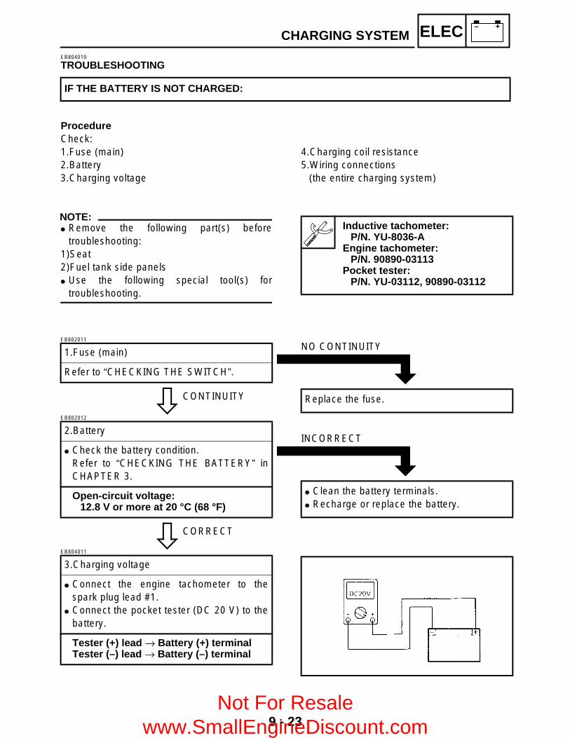
9 - 23
– +ELECCHARGING SYSTEMEB804010
TROUBLESHOOTING
ProcedureCheck:1.Fuse (main)2.Battery3.Charging voltage
IF THE BATTERY IS NOT CHARGED:
4.Charging coil resistance5.Wiring connections
(the entire charging system)
NOTE: Remove the following part(s) before
troubleshooting:1)Seat2)Fuel tank side panels Use the following special tool(s) for
troubleshooting.
Inductive tachometer:P/N. YU-8036-A
Engine tachometer:P/N. 90890-03113
Pocket tester:P/N. YU-03112, 90890-03112
EB802011
CONTINUITY
1.Fuse (main)
Refer to “CHECKING THE SWITCH”.
NO CONTINUITY
Replace the fuse.
EB802012
CORRECT
2.Battery
Check the battery condition.Refer to “CHECKING THE BATTERY” inCHAPTER 3.
Open-circuit voltage:12.8 V or more at 20 °C (68 °F)
INCORRECT
Clean the battery terminals. Recharge or replace the battery.
EB804011
3.Charging voltage
Connect the engine tachometer to thespark plug lead #1.
Connect the pocket tester (DC 20 V) to thebattery.
Tester (+) lead → Battery (+) terminalTester (–) lead → Battery (–) terminal
Not For Resale www.SmallEngineDiscount.com

9 - 24
– +ELECCHARGING SYSTEM
OUT OFSPECIFICATION
Start the engine and accelerate to about3,000 r/min.
Charging voltage:14 V at 3,000 r/min
NOTE:Use a fully charged battery.
MEETS SPECIFICATION
The charging circuit is not faulty.
EB804012
MEETSSPECIFICATION
4.Charging coil resistance
Disconnect the AC magneto coupler fromthe wire harness.
Connect the pocket tester (Ω × 1) to thecharging coils.
Tester (+) lead → White terminal 1 Tester (–) lead → White terminal 2
Tester (+) lead → White terminal 1 Tester (–) lead → White terminal 3
Measure the stator coil resistance.
Charging coil resistance:0.41 ~ 0.61 Ω at 20 °C (68 °F)
OUT OF SPECIFICATION
Replace the pickup coil/stator assembly.
EB804015
CORRECT
5.Wiring connections
Check the connections of the entirecharging system.Refer to “CIRCUIT DIAGRAM”.
Replace the rectifier/regulator.
POOR CONNECTION
Properly connect the charging system.
Not For Resale www.SmallEngineDiscount.com

9 - 25
– +ELECLIGHTING SYSTEMEB805000
LIGHTING SYSTEMCIRCUIT DIAGRAM
OF
F
W/B
BB/
RB/
RB
W/B
C
D
OB
BO
LB
BL
YB
rB
B
B/Y
B
BB
(GR
AY)
(GR
AY)
D
WIR
E H
AR
NE
SS
SU
B-W
IRE
H
AR
NE
SS
4
Br
Sb
L/B
R/B
Br/B
B/Y
L/B
Sb
Br
B/Y
Br/B
R/B
Br
YL
L/B
GB
LY
R/Y
BG
L/B
WS
bG
/L
L/W
B/R
W/L
G/L
Sb
W
W/L
B/R
L/W
W/R
Sb
L/WG/
W
Sb
W/R
G/W
L/W
W/B
L/Y
Br
W/R
L/Y
W/B
W/R
Br
W/G
R
W/R
W/G
RW/
G
W/L
W/R
RB
r
RBr
/L
Br
R
Br/L
R
L/G
L/R
L/B
Sb
L/R
L/G
Sb
L/B
R L/W
L/B
R/B
L/WO
B
B/Y
RW
/RW
/G
WY/
B
B/R
G/L
G/W
W/B
Sb
G/R
(BLA
CK
)
(BLA
CK
)(B
LAC
K)
C
WIR
E H
AR
NE
SS
SU
B-W
IRE
H
AR
NE
SS
3
B
WIR
E H
AR
NE
SS
SU
B-W
IRE
H
AR
NE
SS
2
A
WIR
E H
AR
NE
SS
SU
B-W
IRE
H
AR
NE
SS
1
(BLA
CK
)
(BLA
CK
)
(BLA
CK
)
(GR
AY)
(GR
AY)
(GR
AY)
(GR
AY)
(BLA
CK
)(B
LAC
K)
Gy
G/R
Br
B
G/R
Gy
BB
r
(GR
AY)
(GR
AY)
WW
WW
WW
OF
FO
N
OF
F
2WD
4WD
LOC
K
W/G
Br/
L
R/G
L/B
G/W
G/W
L/W
Br
Br
W/R
W/GR
W/G
W/R
L/W
L/Y
R/B
G/W
Y/B
G/R Sb
G/L
W/B B
/R
B/Y
B/Y
L/Y
R/G
Br/
RB
/RW
/BG
/L
G/R
W/L
W/L
R
Br
Sb
O
CB
O
B WW
B
B
B
W
B
W W W
W W W
R
RR
R
B
WW
WR
B
BP
US
H
_
R R B BB B
BB
R R
R
D
W/R
W/R
DL/W
B/R
B/R
L/W
D
A
Br/
B
Br/
B
Br/
B
B
B
W/B
W/B
W/B
A
Sb
Sb
O/R
P B/W
L/Y
W
B
G/R
R/G B
G/R
R/G
B
YG
B
YG
B
YG
B
B/Y
Br/R
Br/R
L/R
B
(BLA
CK
)
Br/B
Br/R
Br/R
L/G
B
(BLA
CK
)
Br/
R
L/R
B/Y
Br/
R
B
Br/
R
L/G
Br/
B
B
B B B
B
Br
Sb
L/BL/
G
Br B
/YS
bL/
B
B/Y
L/R
Y/B
Br/
RL/
R
Gy
Gy
G/R
Br/B
W/B
BB
/YB
/R
BL/
BS
bB
r
BB
BB
A
Y/B
Gy
Br/R
L/R
Br/
L
Br/
R
Br/
L
L/B
R/B
Br/
L
R/W
R/W
Br/
L
R/Y
Br/
L
Br
R/B
R/B
R/Y
P B
B
B
GY
GY
BL
L
L(B
LAC
K)
(BLA
CK
)
R/B
R/WR/B
R/W
B
GY
B
LY
YG
B
(DA
RK
GR
AY
)
(BLA
CK
)(B
LAC
K)
LR
/B
Br Y
YB
rB
B
(BLA
CK
)(B
LAC
K)
Br Y
12
3
45
67
8
9
0 A
B
C
D E
F
G
HIJKLM
OP
Q
R
ST
U
V
W
Y
\
]
b
d
ei
gh
b
^a
XZ
[c
f
N
3M
ain
switc
h5
Bat
tery
6M
ain
fuse
[H
eadl
ight
fuse
]Li
ght s
witc
hb
Hea
dlig
hti
Tai
l/bra
ke li
ght
Not For Resale www.SmallEngineDiscount.com

9 - 26
– +ELECLIGHTING SYSTEMEB805010
TROUBLESHOOTING
ProcedureCheck:1.Fuse (main, headlight)2.Battery3.Main switch
IF THE HEADLIGHT AND/OR TAILLIGHT FAIL TO COME ON:
4.Light switch5.Wiring connections
(the entire lighting system)
NOTE: Remove the following part(s) before
troubleshooting:1)Seat2)Front carrier3)Front fender panel Use the following special tool(s) for
troubleshooting.
Pocket tester:P/N. YU-03112, 90890-03112
EB802011
CONTINUITY
1.Fuse (main, headlight)
Refer to “CHECKING THE SWITCH”.
NO CONTINUITY
Replace the fuse.
EB802012
CORRECT
2.Battery
Check the battery condition.Refer to “CHECKING THE BATTERY” inCHAPTER 3.
Open-circuit voltage:12.8 V or more at 20 °C (68 °F)
*
INCORRECT
Clean the battery terminals. Recharge or replace the battery.
Not For Resale www.SmallEngineDiscount.com
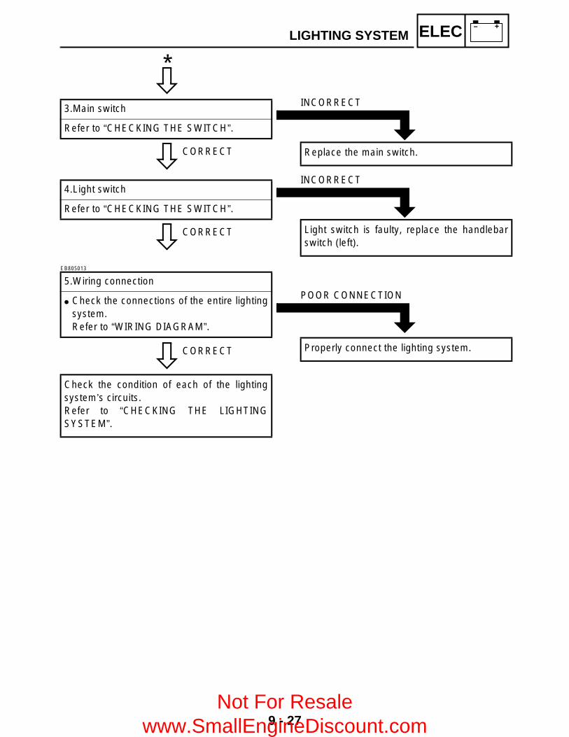
9 - 27
– +ELECLIGHTING SYSTEM
C0NTINUITY
CORRECT
3.Main switch
Refer to “CHECKING THE SWITCH”.
*
INCORRECT
Replace the main switch.
CORRECT
4.Light switch
Refer to “CHECKING THE SWITCH”.
INCORRECT
Light switch is faulty, replace the handlebarswitch (left).
EB805013
CORRECT
5.Wiring connection
Check the connections of the entire lightingsystem.Refer to “WIRING DIAGRAM”.
Check the condition of each of the lightingsystem’s circuits.Refer to “CHECKING THE LIGHTINGSYSTEM”.
POOR CONNECTION
Properly connect the lighting system.
Not For Resale www.SmallEngineDiscount.com

9 - 28
– +ELECLIGHTING SYSTEMEB805020
CHECKING THE LIGHTING SYSTEM1.If the headlights fail to come on:
CONTINUITY
1.Bulb and bulb socket
Check the bulb and bulb socket forcontinuity.
NO CONTINUITY
Replace the bulb and/or bulb socket.
2.Voltage
Connect the pocket tester (DC 20 V) to theheadlight couplers.
Tester (+) lead → Green terminal 1 or Yellow terminal 2
Tester (–) lead → Black terminal 3
ÈWhen the light switch is on “ ”.ÉWhen the light switch is on “ ”.
È É
MEETSSPECIFICATION
Turn the main switch to “ON”. Turn the light switch to “ ” or “ ”. Check the voltage (12 V) of the “Green”
and “Yellow” leads on the bulb socketconnector.
This circuit is not faulty.
OUT OF SPECIFICATION
The wiring circuit from the main switch to thebulb socket connector is faulty, repair it.
Not For Resale www.SmallEngineDiscount.com

9 - 29
– +ELECLIGHTING SYSTEMEB805021
2.If the taillight fails to come on:
CONTINUITY
1.Bulb and bulb socket
Check the bulb and bulb socket forcontinuity.
NO CONTINUITY
Replace the bulb and/or bulb socket.
2.Voltage
Connect the pocket tester (20 V) to the bulbsocket coupler.
Tester (+) lead → Blue lead 1 Tester (–) lead → Black lead 2
LYB
1
2
MEETSSPECIFICATION
Turn the main switch to “ON”. Turn the light switch to “ ” or “ ”. Check the voltage (12 V) of the “Blue” lead
on the bulb socket connector.
This circuit is not faulty.
OUT OF SPECIFICATION
The wiring circuit from the main switch to thebulb socket connector is faulty, repair it.
Not For Resale www.SmallEngineDiscount.com

9 - 30
– +ELECSIGNAL SYSTEMEB806000
SIGNAL SYSTEMCIRCUIT DIAGRAM
2WD
4WD
LOC
K
W/B
BB/
RB/
RB
W/B
C
D
OB
BO
LB
BL
YB
rB
B
B/Y
B
BB
(GR
AY)
(GR
AY)
D
WIR
E H
AR
NE
SS
SU
B-W
IRE
H
AR
NE
SS
4
Br
Sb
L/B
R/B
Br/B
B/Y
L/B
Sb
Br
B/Y
Br/B
R/B
Br
YL
L/B
GB
LY
R/Y
BG
L/B
WS
bG
/L
L/W
B/R
W/L
G/L
Sb
W
W/L
B/R
L/W
W/R
Sb
L/WG/
W
Sb
W/R
G/W
L/W
W/B
L/Y
Br
W/R
L/Y
W/B
W/R
Br
W/G
R
W/R
W/G
RW/
G
W/L
W/R
RB
r
RBr
/L
Br
R
Br/L
R
L/G
L/R
L/B
Sb
L/R
L/G
Sb
L/B
R L/W
L/B
R/B
L/WO
B
B/Y
RW
/RW
/G
WY/
B
B/R
G/L
G/W
W/B
Sb
G/R
(BLA
CK
)
(BLA
CK
)(B
LAC
K)
C
WIR
E H
AR
NE
SS
SU
B-W
IRE
H
AR
NE
SS
3
B
WIR
E H
AR
NE
SS
SU
B-W
IRE
H
AR
NE
SS
2
A
WIR
E H
AR
NE
SS
SU
B-W
IRE
H
AR
NE
SS
1
(BLA
CK
)
(BLA
CK
)
(BLA
CK
)
(GR
AY)
(GR
AY)
(GR
AY)
(GR
AY)
(BLA
CK
)(B
LAC
K)
Gy
G/R
Br
B
G/R
Gy
BB
r
(GR
AY)
(GR
AY)
WW
WW
WW
OF
FO
N
OF
F
2WD
4WD
LOC
K
W/G
Br/
L
R/G
L/B
G/W
G/W
L/W
Br
Br
W/R
W/GR
W/G
W/R
L/W
L/Y
R/B
G/W
Y/B
G/R Sb
G/L
W/B B
/R
B/Y
B/Y
L/Y
R/G
Br/
RB
/RW
/BG
/L
G/R
W/L
W/L
R
Br
Sb
O
CB
O
B WW
B
B
B
W
B
W W W
W W W
R
RR
R
B
WW
WR
B
BP
US
H
_
R R B BB B
BB
R R
R
D
W/R
W/R
DL/W
B/R
B/R
L/W
D
A
Br/
B
Br/
B
Br/
B
B
B
W/B
W/B
W/B
A
Sb
Sb
O/R
P B/W
L/Y
W
B
G/R
R/G B
G/R
R/G
B
YG
B
YG
B
YG
B
B/Y
Br/R
Br/R
L/R
B
(BLA
CK
)
Br/B
Br/R
Br/R
L/G
B
(BLA
CK
)
Br/
R
L/R
B/Y
Br/
R
B
Br/
R
L/G
Br/
B
B
B B B
B
Br
Sb
L/BL/
G
Br B
/YS
bL/
B
B/Y
L/R
Y/B
Br/
RL/
R
Gy
Gy
G/R
Br/B
W/B
BB
/YB
/R
BL/
BS
bB
r
BB
BB
A
Y/B
Gy
Br/R
L/R
Br/
L
Br/
R
Br/
L
L/B
R/B
Br/
L
R/W
R/W
Br/
L
R/Y
Br/
L
Br
R/B
R/B
R/Y
P B
B
B
GY
GY
BL
L
L(B
LAC
K)
(BLA
CK
)
R/B
R/WR/B
R/W
B
GY
B
LY
YG
B
(DA
RK
GR
AY
)
(BLA
CK
)(B
LAC
K)
LR
/B
Br Y
YB
rB
B
(BLA
CK
)(B
LAC
K)
Br Y
12
3
45
67
8
9
0 A
B
C
D E
F
G
HIJKLM
OP
Q
R
ST
U
V
W
Y
\
]
b
d
ei
gh
b
^a
XZ
[c
f
N
Not For Resale www.SmallEngineDiscount.com

9 - 31
– +ELECSIGNAL SYSTEM
3 Main switch4 Backup fuse5 Battery6 Main fuse9 Reverse switch0 CDI unitD Speed sensorE Thermo switch 1G Multi-function meterH Differential gear lock indicator lightI Coolant temperature warning lightJ Reverse indicator lightK Neutral indicator lightL Park indicator lightM High-range indicator lightN Low-range indicator lightO Low-range switchP High-range switchQ Neutral switchV On-command four-wheel drive switch and differential gear lock switchW Gear motorZ Ignition fusef Signaling system fuseg Front brake light switch h Rear brake light switchi Tail/brake light
Not For Resale www.SmallEngineDiscount.com

9 - 32
– +ELECSIGNAL SYSTEMEB806010
TROUBLESHOOTING
ProcedureCheck:1.Fuse (main, backup, ignition, signaling system)2.Battery3.Main switch4.Wiring connections
(the entire signal system)
IF THE BRAKE LIGHT AND/OR INDICATOR LIGHT FAILS TO COME ON:
NOTE: Remove the following part(s) before
troubleshooting:1)Seat2)Fuel tank3)Air filter case4)Front carrier5)Front fender panel Use the following special tool(s) for
troubleshooting.
Pocket tester:P/N. YU-03112, 90890-03112
EB802011
CONTINUITY
1.Fuse (main, backup, ignition, signaling system)
Refer to “CHECKING THE SWITCH”.
NO CONTINUITY
Replace the fuse.
EB802012
CORRECT
2.Battery
Check the battery condition.Refer to “CHECKING THE BATTERY” inCHAPTER 3.
Open-circuit voltage:12.8 V or more at 20 °C (68 °F)
*
INCORRECT
Clean the battery terminals. Recharge or replace the battery.
Not For Resale www.SmallEngineDiscount.com

9 - 33
– +ELECSIGNAL SYSTEM
C0NTINUITY
CORRECT
3.Main switch
Refer to “CHECKING THE SWITCH”.
*
INCORRECT
Replace the main switch.
EB806011
CORRECT
4.Wiring connections
Check the connections of the entire signalsystem.Refer to “CIRCUIT DIAGRAM”.
Check the condition of each of the signalsystem’s circuits. Refer to “CHECKING THE SIGNALSYSTEM”.
POOR CONNECTION
Properly connect the signal system.
Not For Resale www.SmallEngineDiscount.com
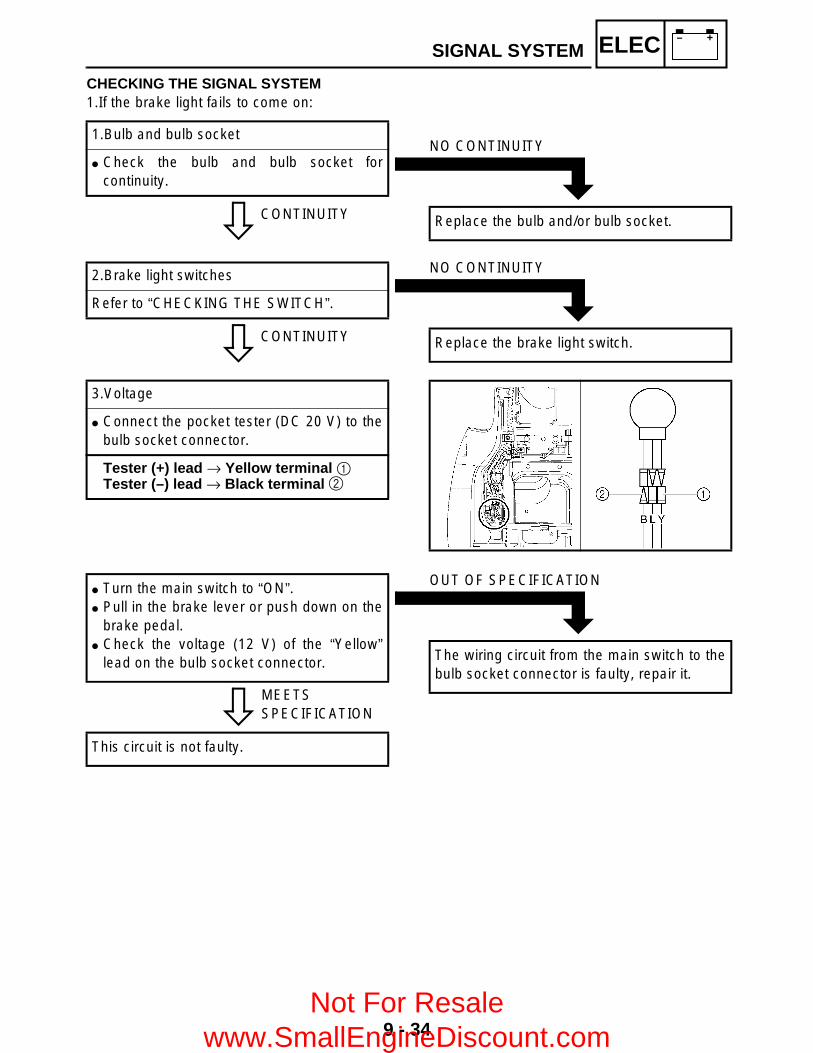
9 - 34
– +ELECSIGNAL SYSTEM
CHECKING THE SIGNAL SYSTEM1.If the brake light fails to come on:
CONTINUITY
1.Bulb and bulb socket
Check the bulb and bulb socket forcontinuity.
NO CONTINUITY
Replace the bulb and/or bulb socket.
CONTINUITY
2.Brake light switches
Refer to “CHECKING THE SWITCH”.
NO CONTINUITY
Replace the brake light switch.
3.Voltage
Connect the pocket tester (DC 20 V) to thebulb socket connector.
Tester (+) lead → Yellow terminal 1 Tester (–) lead → Black terminal 2
MEETSSPECIFICATION
Turn the main switch to “ON”. Pull in the brake lever or push down on the
brake pedal. Check the voltage (12 V) of the “Yellow”
lead on the bulb socket connector.
This circuit is not faulty.
OUT OF SPECIFICATION
The wiring circuit from the main switch to thebulb socket connector is faulty, repair it.
Not For Resale www.SmallEngineDiscount.com

9 - 35
– +ELECSIGNAL SYSTEMEB806024
2.If the indicator lights fails to come on:
CONTINUITY
1.Neutral switch
Refer to “CHECKING THE SWITCH”.
NO CONTINUITY
Replace the neutral switch.
CONTINUITY
2.High-range switch
Refer to “CHECKING THE SWITCH”.
NO CONTINUITY
Replace the high-range switch.
CONTINUITY
3.Low-range switch
Refer to “CHECKING THE SWITCH”.
NO CONTINUITY
Replace the low-range switch.
CONTINUITY
5.Four-wheel drive switch
Refer to “CHECKING THE SWITCH”.
Replace the meter assembly.
NO CONTINUITY
Replace the four-wheel drive switch.
CONTINUITY
4.Reverse switch
Refer to “CHECKING THE SWITCH”.
NO CONTINUITY
Replace the reverse switch.
Not For Resale www.SmallEngineDiscount.com

9 - 36
– +ELECSIGNAL SYSTEM
3.If the coolant temperature warning light does not come on: Check that the light comes on when the main switch is set to “ON”. Check that the light comes on when the coolant temperature is 120 ± 3 °C (248 ± 5.4 °F) or higher
and that the light remains on when the coolant temperature drops to 113 °C (235.4 °F).
GOODCONDITION
1.Thermo switch 1
Remove the thermo switch 1 from thecylinder head.
Connect the pocket tester (Ω × 1) to thethermo switch 1 1.
Immerse the thermo switch 1 in coolant 2. Check the thermo switch 1 for continuity.
While heating the coolant use a thermometer3 to record the temperatures.
Test step
Coolant temperatureContinuity
Thermo switch 1
1Less than 120 ± 3 °C
(248 ± 5.4 °F) NO
2 More than 120 ± 3 °C(248 ± 5.4 °F)
YES
3 More than 113 °C(235.4 °F) YES
4Less than 113 °C
(235.4 °F) NO
Test steps 1 & 2: Heating phaseTest steps 3 & 4: Cooling phase
È The thermo switch 1 circuit is open and thecoolant temperature warning light is off.
É The thermo switch 1 circuit is closed and thecoolant temperature warning light is come on.
WARNINGHandle the thermo switch 1 with specialcare.Never subject it to a strong shock or allowit to be dropped. Should it be dropped, itmust be replaced.
T R..
Thermo switch 1:8 Nm (0.8 m • kg, 5.8 ft • lb)Three bond sealock® #10
Replace the meter assembly.
É
È
113 ˚C(235.4 ˚F)
120 ± 3 ˚C(248 ± 5.4 ˚F)
BAD CONDITION
Replace the thermo switch 1.
Not For Resale www.SmallEngineDiscount.com

9 - 37
– +ELECCOOLING SYSTEM
COOLING SYSTEMCIRCUIT DIAGRAM
W/B
BB/
RB/
RB
W/B
C
D
OB
BO
LB
BL
YB
rB
B
B/Y
B
BB
(GR
AY)
(GR
AY)
D
WIR
E H
AR
NE
SS
SU
B-W
IRE
H
AR
NE
SS
4
Br
Sb
L/B
R/B
Br/B
B/Y
L/B
Sb
Br
B/Y
Br/B
R/B
Br
YL
L/B
GB
LY
R/Y
BG
L/B
WS
bG
/L
L/W
B/R
W/L
G/L
Sb
W
W/L
B/R
L/W
W/R
Sb
L/WG/
W
Sb
W/R
G/W
L/W
W/B
L/Y
Br
W/R
L/Y
W/B
W/R
Br
W/G
R
W/R
W/G
RW/
G
W/L
W/R
RB
r
RBr
/L
Br
R
Br/L
R
L/G
L/R
L/B
Sb
L/R
L/G
Sb
L/B
R L/W
L/B
R/B
L/WO
B
B/Y
RW
/RW
/G
WY/
B
B/R
G/L
G/W
W/B
Sb
G/R
(BLA
CK
)
(BLA
CK
)(B
LAC
K)
C
WIR
E H
AR
NE
SS
SU
B-W
IRE
H
AR
NE
SS
3
B
WIR
E H
AR
NE
SS
SU
B-W
IRE
H
AR
NE
SS
2
A
WIR
E H
AR
NE
SS
SU
B-W
IRE
H
AR
NE
SS
1
(BLA
CK
)
(BLA
CK
)
(BLA
CK
)
(GR
AY)
(GR
AY)
(GR
AY)
(GR
AY)
(BLA
CK
)(B
LAC
K)
Gy
G/R
Br
B
G/R
Gy
BB
r
(GR
AY)
(GR
AY)
WW
WW
WW
OF
FO
N
OF
F
2WD
4WD
LOC
K
W/G
Br/
L
R/G
L/B
G/W
G/W
L/W
Br
Br
W/R
W/GR
W/G
W/R
L/W
L/Y
R/B
G/W
Y/B
G/R Sb
G/L
W/B B
/R
B/Y
B/Y
L/Y
R/G
Br/
RB
/RW
/BG
/L
G/R
W/L
W/L
R
Br
Sb
O
CB
O
B WW
B
B
B
W
B
W W W
W W W
R
RR
R
B
WW
WR
B
BP
US
H
_
R R B BB B
BB
R R
R
D
W/R
W/R
DL/W
B/R
B/R
L/W
D
A
Br/
B
Br/
B
Br/
B
B
B
W/B
W/B
W/B
A
Sb
Sb
O/R
P B/W
L/Y
W
B
G/R
R/G B
G/R
R/G
B
YG
B
YG
B
YG
B
B/Y
Br/R
Br/R
L/R
B
(BLA
CK
)
Br/B
Br/R
Br/R
L/G
B
(BLA
CK
)
Br/
R
L/R
B/Y
Br/
R
B
Br/
R
L/G
Br/
B
B
B B B
B
Br
Sb
L/BL/
G
Br B
/YS
bL/
B
B/Y
L/R
Y/B
Br/
RL/
R
Gy
Gy
G/R
Br/B
W/B
BB
/YB
/R
BL/
BS
bB
r
BB
BB
A
Y/B
Gy
Br/R
L/R
Br/
L
Br/
R
Br/
L
L/B
R/B
Br/
L
R/W
R/W
Br/
L
R/Y
Br/
L
Br
R/B
R/B
R/Y
P B
B
B
GY
GY
BL
L
L(B
LAC
K)
(BLA
CK
)
R/B
R/WR/B
R/W
B
GY
B
LY
YG
B
(DA
RK
GR
AY
)
(BLA
CK
)(B
LAC
K)
LR
/B
Br Y
YB
rB
B
(BLA
CK
)(B
LAC
K)
Br Y
12
3
45
67
8
9
0 A
B
C
D E
F
G
HIJKLM
OP
Q
R
ST
U
V
W
Y
\
]
b
d
ei
gh
b
^a
XZ
[c
f
N
3M
ain
switc
h5
Bat
tery
6M
ain
fuse
cC
ircui
t bre
aker
(fa
n m
otor
)d
The
rmo
switc
h 2
eF
an m
otor
Not For Resale www.SmallEngineDiscount.com
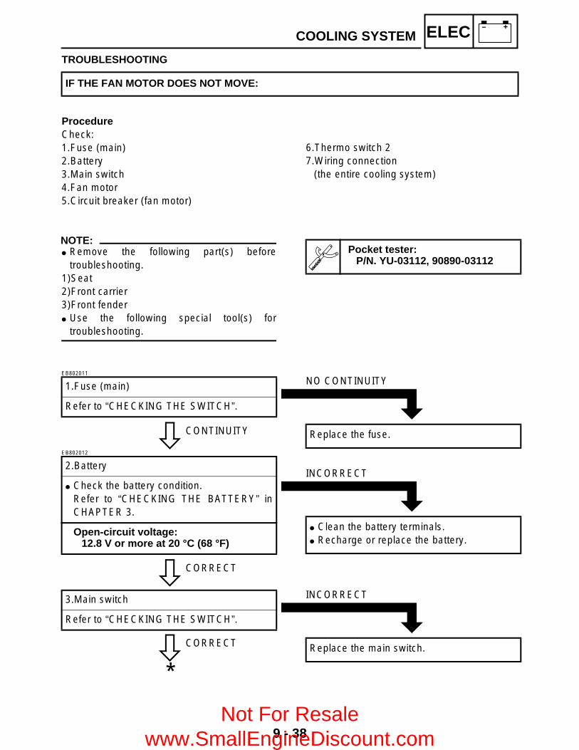
9 - 38
– +ELECCOOLING SYSTEM
TROUBLESHOOTING
ProcedureCheck:1.Fuse (main)2.Battery3.Main switch4.Fan motor5.Circuit breaker (fan motor)
IF THE FAN MOTOR DOES NOT MOVE:
6.Thermo switch 27.Wiring connection
(the entire cooling system)
NOTE: Remove the following part(s) before
troubleshooting.1)Seat2)Front carrier3)Front fender Use the following special tool(s) for
troubleshooting.
Pocket tester:P/N. YU-03112, 90890-03112
EB802011
CONTINUITY
1.Fuse (main)
Refer to “CHECKING THE SWITCH”.
NO CONTINUITY
Replace the fuse.
EB802012
CORRECT
2.Battery
Check the battery condition.Refer to “CHECKING THE BATTERY” inCHAPTER 3.
Open-circuit voltage:12.8 V or more at 20 °C (68 °F)
INCORRECT
Clean the battery terminals. Recharge or replace the battery.
CORRECT
3.Main switch
Refer to “CHECKING THE SWITCH”.
*
INCORRECT
Replace the main switch.
Not For Resale www.SmallEngineDiscount.com

9 - 39
– +ELECCOOLING SYSTEM
C0NTINUITY
TURNS
4.Fan motor
Disconnect the fan motor coupler. Connect the battery (12 V) as shown.
Battery (+) lead → Blue terminal 1 Battery (–) lead → Black terminal 2
Check the operation of the fan motor.
*
DOES NOT TURN
Replace the fan motor.
MEETSSPECIFICATION
5.Circuit breaker (fan motor)
Remove the circuit breaker from the wireharness.
Connect the pocket tester (Ω × 1) to thecircuit breaker.
Circuit breaker resistance:Zero Ω at 20 °C (68 °F)
*
OUT OF SPECIFICATION
Replace the circuit breaker.
Not For Resale www.SmallEngineDiscount.com
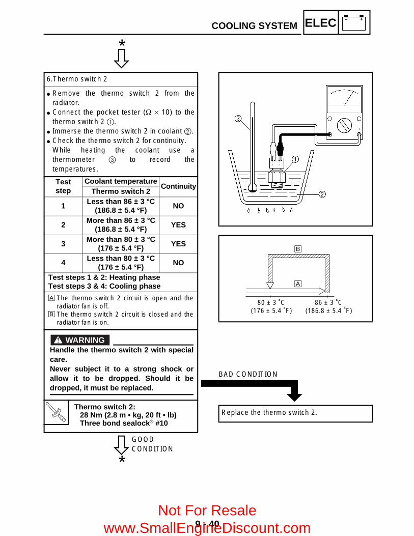
9 - 40
– +ELECCOOLING SYSTEM
C0NTINUITY
GOODCONDITION
6.Thermo switch 2
Remove the thermo switch 2 from theradiator.
Connect the pocket tester (Ω × 10) to thethermo switch 2 1.
Immerse the thermo switch 2 in coolant 2. Check the thermo switch 2 for continuity.
While heating the coolant use athermometer 3 to record thetemperatures.
Test step
Coolant temperatureContinuity
Thermo switch 2
1 Less than 86 ± 3 °C(186.8 ± 5.4 °F) NO
2More than 86 ± 3 °C
(186.8 ± 5.4 °F) YES
3More than 80 ± 3 °C
(176 ± 5.4 °F) YES
4 Less than 80 ± 3 °C(176 ± 5.4 °F)
NO
Test steps 1 & 2: Heating phaseTest steps 3 & 4: Cooling phase
È The thermo switch 2 circuit is open and theradiator fan is off.
É The thermo switch 2 circuit is closed and theradiator fan is on.
WARNINGHandle the thermo switch 2 with specialcare.Never subject it to a strong shock orallow it to be dropped. Should it bedropped, it must be replaced.
T R..
Thermo switch 2:28 Nm (2.8 m • kg, 20 ft • lb)Three bond sealock® #10
*
*
É
È
80 ± 3 ˚C(176 ± 5.4 ˚F)
86 ± 3 ˚C(186.8 ± 5.4 ˚F)
BAD CONDITION
Replace the thermo switch 2.
Not For Resale www.SmallEngineDiscount.com
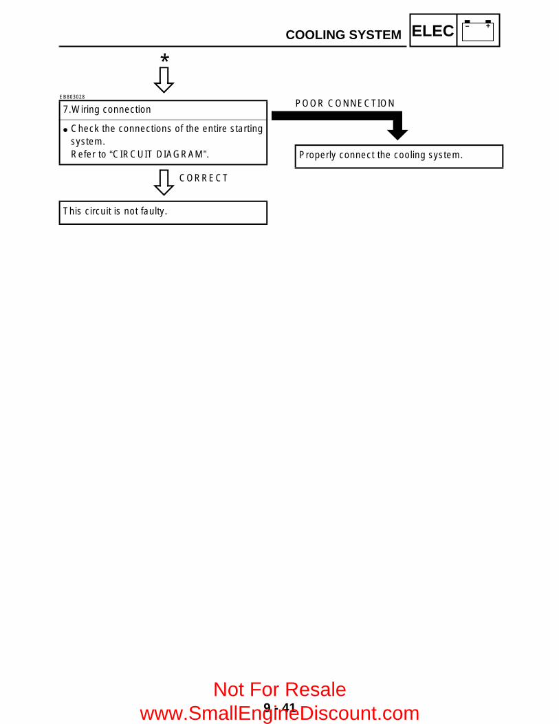
9 - 41
– +ELECCOOLING SYSTEM
C0NTINUITY
EB803028
CORRECT
7.Wiring connection
Check the connections of the entire startingsystem.Refer to “CIRCUIT DIAGRAM”.
This circuit is not faulty.
*
POOR CONNECTION
Properly connect the cooling system.
Not For Resale www.SmallEngineDiscount.com

9 - 42
– +ELEC2WD/4WD SELECTING SYSTEM
2WD/4WD SELECTING SYSTEMCIRCUIT DIAGRAM
W/B
BB/
RB/
RB
W/B
C
D
OB
BO
LB
BL
YB
rB
B
B/Y
B
BB
(GR
AY)
(GR
AY)
D
WIR
E H
AR
NE
SS
SU
B-W
IRE
H
AR
NE
SS
4
Br
Sb
L/B
R/B
Br/B
B/Y
L/B
Sb
Br
B/Y
Br/B
R/B
Br
YL
L/B
GB
LY
R/Y
BG
L/B
WS
bG
/L
L/W
B/R
W/L
G/L
Sb
W
W/L
B/R
L/W
W/R
Sb
L/WG/
W
Sb
W/R
G/W
L/W
W/B
L/Y
Br
W/R
L/Y
W/B
W/R
Br
W/G
R
W/R
W/G
RW/
G
W/L
W/R
RB
r
RBr
/L
Br
R
Br/L
R
L/G
L/R
L/B
Sb
L/R
L/G
Sb
L/B
R L/W
L/B
R/B
L/WO
B
B/Y
RW
/RW
/G
WY/
B
B/R
G/L
G/W
W/B
Sb
G/R
(BLA
CK
)
(BLA
CK
)(B
LAC
K)
C
WIR
E H
AR
NE
SS
SU
B-W
IRE
H
AR
NE
SS
3
B
WIR
E H
AR
NE
SS
SU
B-W
IRE
H
AR
NE
SS
2
A
WIR
E H
AR
NE
SS
SU
B-W
IRE
H
AR
NE
SS
1
(BLA
CK
)
(BLA
CK
)
(BLA
CK
)
(GR
AY)
(GR
AY)
(GR
AY)
(GR
AY)
(BLA
CK
)(B
LAC
K)
Gy
G/R
Br
B
G/R
Gy
BB
r
(GR
AY)
(GR
AY)
WW
WW
WW
OF
FO
N
OF
F
2WD
4WD
LOC
K
W/G
Br/
L
R/G
L/B
G/W
G/W
L/W
Br
Br
W/R
W/GR
W/G
W/R
L/W
L/Y
R/B
G/W
Y/B
G/R Sb
G/L
W/B B
/R
B/Y
B/Y
L/Y
R/G
Br/
RB
/RW
/BG
/L
G/R
W/L
W/L
R
Br
Sb
O
CB
O
B WW
B
B
B
W
B
W W W
W W W
R
RR
R
B
WW
WR
B
BP
US
H
_
R R B BB B
BB
R R
R
D
W/R
W/R
DL/W
B/R
B/R
L/W
D
A
Br/
B
Br/
B
Br/
B
B
B
W/B
W/B
W/B
A
Sb
Sb
O/R
P B/W
L/Y
W
B
G/R
R/G B
G/R
R/G
B
YG
B
YG
B
YG
B
B/Y
Br/R
Br/R
L/R
B
(BLA
CK
)
Br/B
Br/R
Br/R
L/G
B
(BLA
CK
)
Br/
R
L/R
B/Y
Br/
R
B
Br/
R
L/G
Br/
B
B
B B B
B
Br
Sb
L/BL/
G
Br B
/YS
bL/
B
B/Y
L/R
Y/B
Br/
RL/
R
Gy
Gy
G/R
Br/B
W/B
BB
/YB
/R
BL/
BS
bB
r
BB
BB
A
Y/B
Gy
Br/R
L/R
Br/
L
Br/
R
Br/
L
L/B
R/B
Br/
L
R/W
R/W
Br/
L
R/Y
Br/
L
Br
R/B
R/B
R/Y
P B
B
B
GY
GY
BL
L
L(B
LAC
K)
(BLA
CK
)
R/B
R/WR/B
R/W
B
GY
B
LY
YG
B
(DA
RK
GR
AY
)
(BLA
CK
)(B
LAC
K)
LR
/B
Br Y
YB
rB
B
(BLA
CK
)(B
LAC
K)
Br Y
12
3
45
67
8
9
0 A
B
C
D E
F
G
HIJKLM
OP
Q
R
ST
U
V
W
Y
\
]
b
d
ei
gh
b
^a
XZ
[c
f
N
3 Main switch5 Battery6 Main fuse0 CDI unitR Four-wheel drive fuseS Four-wheel drive relay 1T Four-wheel drive relay 2U Four-wheel drive relay 3V On-command four-wheel drive switch and
differential gear lock switchW Gear motor
Not For Resale www.SmallEngineDiscount.com

9 - 43
– +ELEC2WD/4WD SELECTING SYSTEMEB803020
TROUBLESHOOTING
ProcedureCheck:1.Fuse (main, four-wheel drive)2.Battery3.Main switch4.Four-wheel drive relay 15.Four-wheel drive relay 26.Four-wheel drive relay 3
IF THE GEAR MOTOR FAILS TO OPERATE:
7.On-command four-wheel drive switch and differential gear lock switch
8.Gear motor9.Wiring connections
(the entire 2WD/4WD selecting system)
NOTE: Remove the following part(s) before
troubleshooting:1)Seat2)Front carrier3)Front fender Use the following special tool(s) for
troubleshooting.
Pocket tester:P/N. YU-03112, 90890-03112
EB802011
CONTINUITY
1.Fuse (main, four-wheel drive)
Refer to “CHECKING THE SWITCH”.
NO CONTINUITY
Replace the fuse.
EB802012
CORRECT
2.Battery
Check the battery condition.Refer to “CHECKING THE BATTERY” inCHAPTER 3.
Open-circuit voltage:12.8 V or more at 20 °C (68 °F)
INCORRECT
Clean the battery terminals. Recharge or replace the battery.
CORRECT
3.Main switch
Refer to “CHECKING THE SWITCH”.
*
INCORRECT
Replace the main switch.
Not For Resale www.SmallEngineDiscount.com
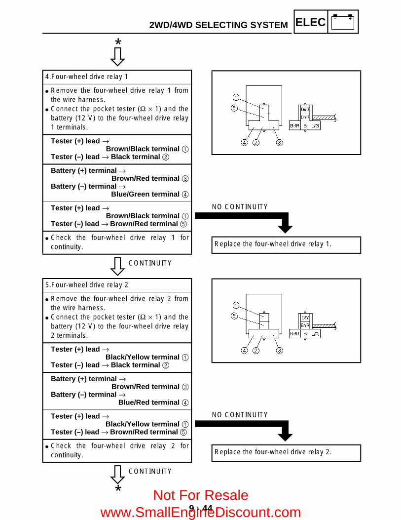
9 - 44
– +ELEC2WD/4WD SELECTING SYSTEM
C0NTINUITY
CONTINUITY
4.Four-wheel drive relay 1
Remove the four-wheel drive relay 1 fromthe wire harness.
Connect the pocket tester (Ω × 1) and thebattery (12 V) to the four-wheel drive relay1 terminals.
Tester (+) lead → Brown/Black terminal 1
Tester (–) lead → Black terminal 2
Battery (+) terminal → Brown/Red terminal 3
Battery (–) terminal → Blue/Green terminal 4
Tester (+) lead → Brown/Black terminal 1
Tester (–) lead → Brown/Red terminal 5
Check the four-wheel drive relay 1 forcontinuity.
*
NO CONTINUITY
Replace the four-wheel drive relay 1.
CONTINUITY
5.Four-wheel drive relay 2
Remove the four-wheel drive relay 2 fromthe wire harness.
Connect the pocket tester (Ω × 1) and thebattery (12 V) to the four-wheel drive relay2 terminals.
Tester (+) lead → Black/Yellow terminal 1
Tester (–) lead → Black terminal 2
Battery (+) terminal → Brown/Red terminal 3
Battery (–) terminal → Blue/Red terminal 4
Tester (+) lead → Black/Yellow terminal 1
Tester (–) lead → Brown/Red terminal 5
Check the four-wheel drive relay 2 forcontinuity.
*
NO CONTINUITY
Replace the four-wheel drive relay 2.
Not For Resale www.SmallEngineDiscount.com

9 - 45
– +ELEC2WD/4WD SELECTING SYSTEM
C0NTINUITY
CONTINUITY
6.Four-wheel drive relay 3
Remove the four-wheel drive relay 3 fromthe wire harness.
Connect the pocket tester (Ω × 1) and thebattery (12 V) to the four-wheel drive relay3 terminals.
Tester (+) lead → Brown/Red terminal 1
Tester (–) lead → Yellow/Black terminal 2
Battery (+) terminal → Brown/Red terminal 1
Battery (–) terminal → Yellow/Black terminal 2
Tester (+) lead → Blue/Red terminal 3 Tester (–) lead → Gray terminal 4
Check the four-wheel drive relay 3 forcontinuity.
*
NO CONTINUITY
Replace the four-wheel drive relay 3.
CORRECT
7.On-command four-wheel drive switch anddifferential gear lock switch
Refer to “CHECKING THE SWITCH”.
*
INCORRECT
Replace the on-command four-wheel driveswitch and differential gear lock switch.
Not For Resale www.SmallEngineDiscount.com

9 - 46
– +ELEC2WD/4WD SELECTING SYSTEM
C0NTINUITY
CORRECT
8.Gear motor
Disconnect the gear motor coupler. Remove the gear motor from the
differential gear case.Refer to “FRONT CONSTANT VELOCITYJOINTS AND DIFFERENTIAL GEAR” inCHAPTER 7.
Connect two C size batteries to the gearmotor terminals 1 (as shown illustrations).
È Check that the pinion gear 2 turnscounterclockwise.
É Check that the pinion gear 2 turns clockwise.
Make sure that the drive gear (shift forksliding gear) operates correctly.
NOTE:When installing the differential gear case inthe gear motor, refer to “FRONT CONSTANTVELOCITY JOINTS AND DIFFERENTIALGEAR” in CHAPTER 7.
*
INCORRECT
Replace the gear motor.
EB803028
CORRECT
9.Wiring connection
Check the connections of the entire 2WD/4WD selecting system.Refer to “CIRCUIT DIAGRAM”.
Replace the CDI unit.
POOR CONNECTION
Properly connect the 2WD/4WD selectingsystem.
È
É
Not For Resale www.SmallEngineDiscount.com
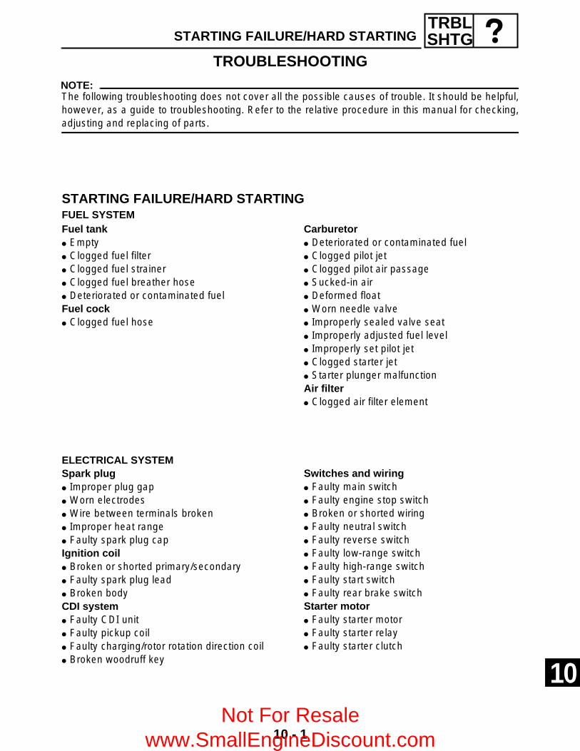
10 - 1
TRBLSHTGSTARTING FAILURE/HARD STARTING
TROUBLESHOOTINGNOTE:The following troubleshooting does not cover all the possible causes of trouble. It should be helpful,however, as a guide to troubleshooting. Refer to the relative procedure in this manual for checking,adjusting and replacing of parts.
STARTING FAILURE/HARD STARTINGFUEL SYSTEM Fuel tank Empty Clogged fuel filter Clogged fuel strainer Clogged fuel breather hose Deteriorated or contaminated fuelFuel cock Clogged fuel hose
ELECTRICAL SYSTEM Spark plug Improper plug gap Worn electrodes Wire between terminals broken Improper heat range Faulty spark plug capIgnition coil Broken or shorted primary/secondary Faulty spark plug lead Broken bodyCDI system Faulty CDI unit Faulty pickup coil Faulty charging/rotor rotation direction coil Broken woodruff key
Carburetor Deteriorated or contaminated fuel Clogged pilot jet Clogged pilot air passage Sucked-in air Deformed float Worn needle valve Improperly sealed valve seat Improperly adjusted fuel level Improperly set pilot jet Clogged starter jet Starter plunger malfunctionAir filter Clogged air filter element
Switches and wiring Faulty main switch Faulty engine stop switch Broken or shorted wiring Faulty neutral switch Faulty reverse switch Faulty low-range switch Faulty high-range switch Faulty start switch Faulty rear brake switchStarter motor Faulty starter motor Faulty starter relay Faulty starter clutch
10 Not For Resale
www.SmallEngineDiscount.com
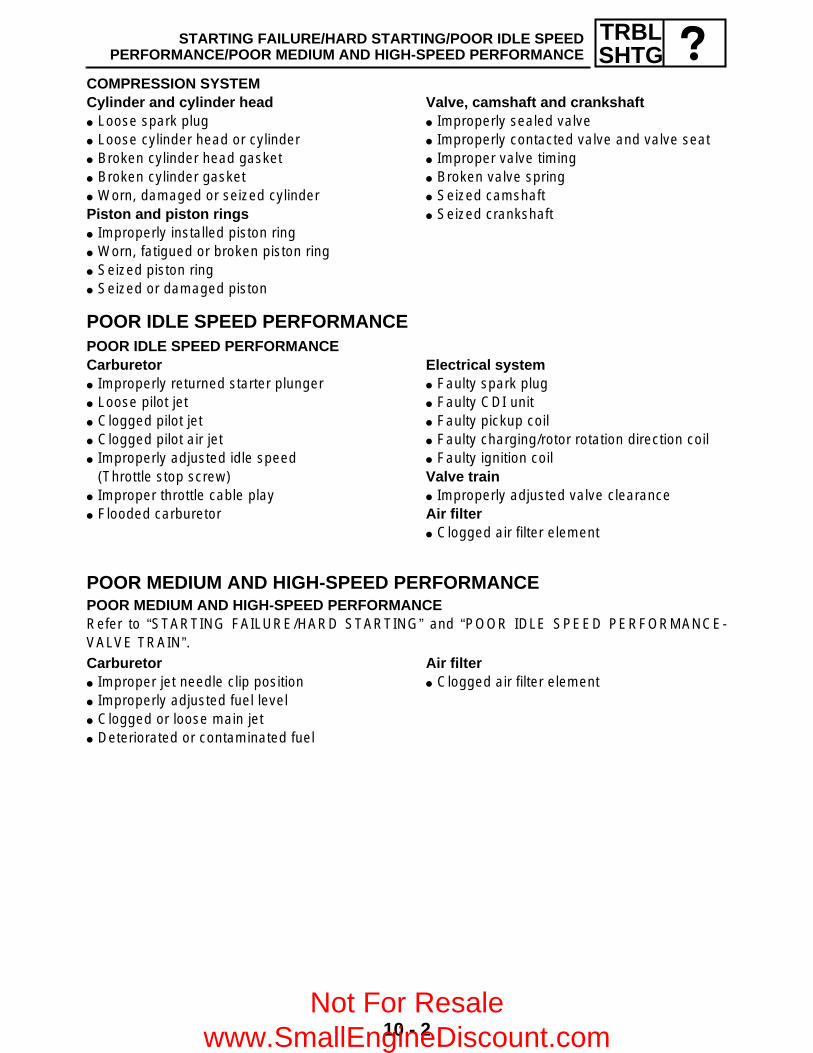
10 - 2
TRBLSHTG
STARTING FAILURE/HARD STARTING/POOR IDLE SPEEDPERFORMANCE/POOR MEDIUM AND HIGH-SPEED PERFORMANCE
COMPRESSION SYSTEM Cylinder and cylinder head Loose spark plug Loose cylinder head or cylinder Broken cylinder head gasket Broken cylinder gasket Worn, damaged or seized cylinderPiston and piston rings Improperly installed piston ring Worn, fatigued or broken piston ring Seized piston ring Seized or damaged piston
Valve, camshaft and crankshaft Improperly sealed valve Improperly contacted valve and valve seat Improper valve timing Broken valve spring Seized camshaft Seized crankshaft
POOR IDLE SPEED PERFORMANCEPOOR IDLE SPEED PERFORMANCECarburetor Improperly returned starter plunger Loose pilot jet Clogged pilot jet Clogged pilot air jet Improperly adjusted idle speed
(Throttle stop screw) Improper throttle cable play Flooded carburetor
Electrical system Faulty spark plug Faulty CDI unit Faulty pickup coil Faulty charging/rotor rotation direction coil Faulty ignition coilValve train Improperly adjusted valve clearanceAir filter Clogged air filter element
POOR MEDIUM AND HIGH-SPEED PERFORMANCEPOOR MEDIUM AND HIGH-SPEED PERFORMANCERefer to “STARTING FAILURE/HARD STARTING” and “POOR IDLE SPEED PERFORMANCE-VALVE TRAIN”.Carburetor Improper jet needle clip position Improperly adjusted fuel level Clogged or loose main jet Deteriorated or contaminated fuel
Air filter Clogged air filter element
Not For Resale www.SmallEngineDiscount.com

10 - 3
TRBLSHTGFAULTY DRIVE TRAIN
FAULTY DRIVE TRAINThe following conditions may indicate damaged shaft drive components:
NOTE:Areas A, B, and C above may be extremely difficult to diagnose. The symptoms are quite subtle anddifficult to distinguish from normal machine operating noise. If there is reason to believe thesecomponents are damaged, remove the components and check them.
Symptoms Possible Causes
1.A pronounced hesitation or “jerky” movementduring acceleration, deceleration, or sustainedspeed. (This must not be confused withengine surging or transmissioncharacteristics.)
2.A “rolling rumble” noticeable at low speed; ahigh-pitched whine; a “clunk” from a shaftdrive component or area.
3.A locked-up condition of the shaft drivemechanism, no power transmitted from theengine to the front and/or rear wheels.
A.Bearing damage.
B.Improper gear lash.
C.Gear tooth damage.
D.Broken drive shaft.
E.Broken gear teeth.
F.Seizure due to lack of lubrication.
G.Small foreign objects lodged between the moving parts.
Not For Resale www.SmallEngineDiscount.com
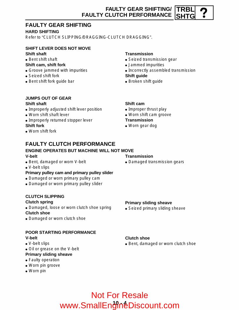
10 - 4
TRBLSHTG
FAULTY GEAR SHIFTING/FAULTY CLUTCH PERFORMANCE
FAULTY GEAR SHIFTINGHARD SHIFTINGRefer to “CLUTCH SLIPPING/DRAGGING-CLUTCH DRAGGING”.
SHIFT LEVER DOES NOT MOVEShift shaft Bent shift shaftShift cam, shift fork Groove jammed with impurities Seized shift fork Bent shift fork guide bar
Transmission Seized transmission gear Jammed impurities Incorrectly assembled transmissionShift guide Broken shift guide
JUMPS OUT OF GEARShift shaft Improperly adjusted shift lever position Worn shift shaft lever Improperly returned stopper leverShift fork Worn shift fork
Shift cam Improper thrust play Worn shift cam grooveTransmission Worn gear dog
FAULTY CLUTCH PERFORMANCEENGINE OPERATES BUT MACHINE WILL NOT MOVEV-belt Bent, damaged or worn V-belt V-belt slipsPrimary pulley cam and primary pulley slider Damaged or worn primary pulley cam Damaged or worn primary pulley slider
Transmission Damaged transmission gears
CLUTCH SLIPPINGClutch spring Damaged, loose or worn clutch shoe springClutch shoe Damaged or worn clutch shoe
Primary sliding sheave Seized primary sliding sheave
POOR STARTING PERFORMANCEV-belt V-belt slips Oil or grease on the V-beltPrimary sliding sheave Faulty operation Worn pin groove Worn pin
Clutch shoe Bent, damaged or worn clutch shoe
Not For Resale www.SmallEngineDiscount.com

10 - 5
TRBLSHTG
FAULTY CLUTCH PERFORMANCE/OVERHEATING/FAULTY BRAKE
POOR SPEED PERFORMANCEV-belt Oil or grease on the V-beltPrimary pulley weight Faulty operation Worn primary pulley weightPrimary fixed sheave Worn primary fixed sheave
Primary sliding sheave Worn primary sliding sheaveSecondary fixed sheave Worn secondary fixed sheaveSecondary sliding sheave Worn secondary sliding sheave
OVERHEATINGOVERHEATINGIgnition system Improper spark plug gap Improper spark plug heat range Faulty CDI unitFuel system Improper carburetor main jet
(improper setting) Improper fuel level Clogged air filter elementCompression system Heavy carbon build-upEngine oil Improper oil level Improper oil viscosity Inferior oil quality
Cooling system Low coolant level Damaged or leaking radiator Faulty radiator cap Bent or damaged radiator fin Damaged or faulty water pump Thermostat stays closed Clogged or damaged oil cooler Damaged hose Improperly connected hose Damaged pipe Improperly connected pipeBrake Brake drag
FAULTY BRAKEPOOR BRAKING EFFECT Worn brake pads Worn disc Air in brake fluid Leaking brake fluid Faulty master cylinder kit cup Faulty caliper kit seal Loose union bolt Broken brake hose and pipe Oily or greasy disc/brake pads Improper brake fluid level
Not For Resale www.SmallEngineDiscount.com

10 - 6
TRBLSHTG
SHOCK ABSORBER MALFUNCTIONMALFUNCTION Bent or damaged damper rod Damaged oil seal lip Fatigued shock absorber spring
SHOCK ABSORBER MALFUNCTION/UNSTABLEHANDLING/LIGHTING SYSTEM
UNSTABLE HANDLINGUNSTABLE HANDLINGHandlebar Improperly installed or bentSteering Incorrect toe-in Bent steering stem Improperly installed steering stem Damaged bearing or bearing race Bent tie-rods Deformed steering knucklesTires Uneven tire pressures on both sides Incorrect tire pressure Uneven tire wear
Wheels Deformed wheel Loose bearing Bent or loose wheel axle Excessive wheel runoutFrame Bent Damaged frame
LIGHTING SYSTEMHEADLIGHT DARK Improper bulb Too many electric accessories Hard charging (broken charging coil and/or
faulty rectifier/regulator) Incorrect connection Improperly grounded Poor contacts (main or light switch) Bulb life expired
BULB BURNT OUT Improper bulb Faulty battery Faulty rectifier/regulator Improperly grounded Faulty main and/or light switch Bulb life expired
Not For Resale www.SmallEngineDiscount.com

YFM450FAR WIRING DIAGRAM
W/B B B/R B/R B W/B
C
D
O B B O
L B
B L
Y Br B B
B/Y B
B B
(GRAY) (GRAY)
D
WIRE HARNESSSUB-WIRE HARNESS 4
Br Sb L/B
R/BBr/B B/Y
L/B Sb Br
B/Y Br/B R/B
Br Y L
L/B G B
L Y R/Y
B G L/B
W Sb G/L
L/W B/R W/L
G/L Sb W
W/L B/R L/W
W/R Sb
L/W G/W
Sb W/R
G/W L/W
W/B L/Y
Br W/R
L/Y W/B
W/R Br
W/G R
W/R W/G
R W/G
W/L W/R
R Br
R Br/L
Br R
Br/L R
L/G L/R
L/B Sb
L/R L/G
Sb L/B
R
L/W L/B
R/B L/W O B
B/Y R W/R W/G
W Y/B
B/R G/L
G/W W/B
Sb G/R
(BLACK)
(BLACK) (BLACK)
C
WIRE HARNESSSUB-WIRE HARNESS 3
B
WIRE HARNESSSUB-WIRE HARNESS 2
A
WIRE HARNESSSUB-WIRE HARNESS 1
(BLACK)
(BLACK)
(BLACK)
(GRAY)(GRAY)
(GRAY)(GRAY)
(BLACK) (BLACK)
Gy G/R
Br B
G/R Gy
B Br
(GRAY) (GRAY)
WW W
WW W
OFFON
OFF
2WD4WDLOCK
W/G
Br/L
R/G
L/B
G/W
G/W
L/W
Br
Br
W/RW/G
R
W/GW/R
L/W
L/Y
R/BG/WY/BG/RSbG/L
W/BB/R
B/Y
B/Y
L/Y
R/G
Br/RB/RW/BG/L
G/R
W/L
W/L
R
Br
Sb
O
CB
O
B
WW
B
B
B
W
B
WWW
WWW
R
R R
R
B
W WWRB
BPUSH
_
R
R
B
B B
B
BB
R
R
R
D
W/R
W/R
D
L/W
B/R B/R
L/W
D
A
Br/B
Br/B
Br/B
B
B
W/BW/B
W/BA
Sb
Sb
O/RP
B/W
L/Y W
B
G/RR/G
B
G/R R/G
B
YG
B
Y G
B
Y G
B
B/YBr/R
Br/R L/RB
(BLACK)
Br/BBr/R
Br/R L/GB
(BLACK)
Br/R
L/R
B/Y
Br/R
B
Br/R
L/G
Br/B
B
B
B
B
B
BrSbL/B
L/G
BrB/YSb
L/B
B/Y
L/R
Y/BBr/RL/R
Gy
Gy
G/R
Br/B W/B BB/Y B/R
BL/B SbBr
BB
BB
A
Y/B Gy
Br/R L/R
Br/L
Br/R
Br/L
L/BR/B
Br/L
R/W
R/W
Br/L
R/Y
Br/L
Br
R/B
R/B R/Y
P
B
B
B
GY
GY
B
L
L
L (BLACK)
(BLACK)
R/BR/W
R/B R/W
B
GY
B
LY
YG
B
(DARK GRAY)
(BLACK) (BLACK)LR/B
Br
Y
Y Br B B
(BLACK) (BLACK)
Br
Y
1 2
3
45
67
8
9
0
A
B
C
D
E
F
G
H I J K L M
OPQ
R
S T
U
V
W
Y
\
]
b
d
ei
gh
b
^ a
XZ[cf
N
1 A.C. magneto2 Rectifier/regulator3 Main switch4 Backup fuse5 Battery6 Main fuse7 Starter relay8 Starter motor9 Reverse switch0 CDI unitA Rear brake switchB Ignition coilC Spark plugD Speed sensorE Thermo switch 1F Meter assemblyG Multi-function meterH Differential gear lock indicator lightI Coolant temperature warning lightJ Reverse indicator lightK Neutral indicator lightL Park indicator lightM High-range indicator lightN Low-range indicator lightO Low-range switchP High-range switchQ Neutral switchR Four-wheel drive fuseS Four-wheel drive relay 1T Four-wheel drive relay 2U Four-wheel drive relay 3V On-command four-wheel drive switch and
differential gear lock switchW Gear motorX Auxiliary DC jack fuseY Auxiliary DC jackZ Ignition fuse[ Headlight fuse\ Handlebar switch (left)] Light switch^ Engine stop switcha Start switchb Headlightc Circuit breaker (fan motor)d Thermo switch 2e Fan motorf Signaling system fuseg Front brake light switch h Rear brake light switchi Tail/brake light
COLOR CODEB ............BlackBr ...........BrownG............GreenL.............BlueO............OrangeP ............PinkR............RedSb ..........Sky blueGy..........Gray
W ...........WhiteY ............YellowB/R.........Black/RedB/Y.........Black/YellowBr/B........Brown/BlackBr/L ........Brown/BlueBr/R .......Brown/RedG/L.........Green/BlueG/R ........Green/Red
G/W........Green/WhiteG/Y.........Green/YellowL/B .........Blue/BlackL/G .........Blue/GreenL/R .........Blue/RedL/W ........Blue/WhiteL/Y .........Blue/YellowR/B.........Red/BlackR/G ........Red/Green
R/W....... Red/WhiteR/Y........ Red/YellowW/B ....... White/BlackW/G....... White/GreenW/L ....... White/BlueW/R....... White/RedY/B ........ Yellow/Black
Not For Resale www.SmallEngineDiscount.com

YAMAHA MOTOR CO., LTD.2500 SHINGAI IWATA SHIZUOKA JAPAN
PRINTED IN U.S.A.Not For Resale www.SmallEngineDiscount.com