yhk yhk–ecm cassette fan coil units · 3 introduction innovating and beautiful design, seven...
TRANSCRIPT
NEW
Wall controls
Cassette Fan Coil Unitswww.eurovent-certification.com
www.certiflash.com
YHKYHK–ECM
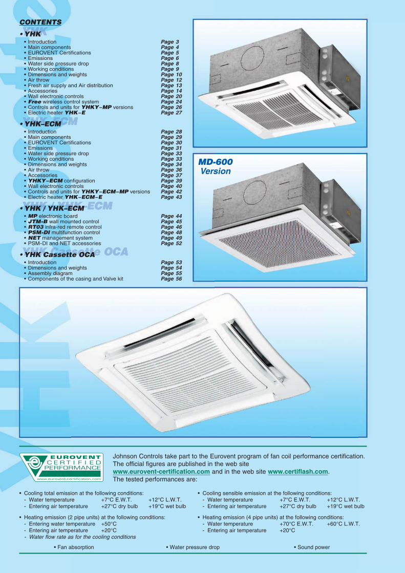
• Fan absorption • Water pressure drop • Sound power
• Heating emission (2 pipe units) at the following conditions: - Entering water temperature +50°C - Entering air temperature +20°C - Water flow rate as for the cooling conditions
• Heating emission (4 pipe units) at the following conditions: - Water temperature +70°C E.W.T. +60°C L.W.T. - Entering air temperature +20°C
• Cooling total emission at the following conditions: - Water temperature +7°C E.W.T. +12°C L.W.T. - Entering air temperature +27°C dry bulb +19°C wet bulb
• Cooling sensible emission at the following conditions: - Water temperature +7°C E.W.T. +12°C L.W.T. - Entering air temperature +27°C dry bulb +19°C wet bulb
Johnson Controls take part to the Eurovent program of fan coil performance certification.The official figures are published in the web sitewww.eurovent-certification.com and in the web site www.certiflash.com.The tested performances are:
CONTENTS
• YHK • Introduction Page 3 • Main components Page 4 • EUROVENT Certifications Page 5 • Emissions Page 6 • Water side pressure drop Page 8 • Working conditions Page 9 • Dimensions and weights Page 10 • Air throw Page 12 • Fresh air supply and Air distribution Page 13 • Accessories Page 14 • Wall electronic controls Page 20 • Free wireless control system Page 24 • Controls and units for YHKY−MP versions Page 26 • Electric heater YHK−E Page 27
• YHK–ECM • Introduction Page 28 • Main components Page 29 • EUROVENT Certifications Page 30 • Emissions Page 31 • Water side pressure drop Page 33 • Working conditions Page 33 • Dimensions and weights Page 34 • Air throw Page 36 • Accessories Page 37 • YHKY−ECM configuration Page 39 • Wall electronic controls Page 40 • Controls and units for YHKY−ECM−MP versions Page 42 • Electric heater YHK−ECM−E Page 43
• YHK / YHK–ECM • MP electronic board Page 44 • JTM-B wall mounted control Page 45 • RT03 infra-red remote control Page 46 • PSM-DI multifunction control Page 48 • NET management system Page 49 • PSM-DI and NET accessories Page 52
• YHK Cassette OCA • Introduction Page 53 • Dimensions and weights Page 54 • Assembly diagram Page 55 • Components of the casing and Valve kit Page 56
MD-600Version

3
Introduction
Innovating and beautiful design, seven different sizes, high control flexibility, easy maintenance: thenew YHK chilled water cassette is the result of an extended technical and design developmentaimed at achieving the highest level in terms of performance, silent operation and controlpossibilities.
The air diffuser has an highly attractive aesthetical appearance, very innovative, and is also ableto offer the best air distribution performance thanks to long computer studies and laboratory tests.The standard colour is RAL 9003, other colours available on request.
The 4 smaller sizes are designed to fit into 600x600 mm false ceiling standard modules. The 3bigger sizes have a dimension of 800x800 mm which allows the best outcome in terms of quiet-ness and of price/performance ratio for these high capacity models.
Every unit can be supplied with 1 battery (2 pipe system) and a possible electric heater or with2 batteries (4 pipe system). Each model can have fresh air intake and a remote air diffuser canbe connected to the unit.
The condensate pump is integralwith the unit, is very quiet and hasa maximum head of 650 mm.
In addition to temperature and speedstandard controls, automatic speedselection is also available. More thanone unit can be connected to a singlecontrol, and the unit control panel canbe installed in a remote position thatfacilitates the maintenance operation.All the YHK units can be suppliedin MP version. This version allows awide range of controls, including theinfra-red remote control, which canmanage one single unit or several unitsby using the Modbus RTU - RS 485communication protocol.The units can be connected to themost common automatic buildingmanagement systems.
It is also possible to use a completelywireless electronic control system basedon radio communication called Free, withgreat advantages in terms of installationflexibility and maximum precision inmeasuring room temperature.
Finally, each unit can be equippedwith a low energy consumption electricmotor that is controlled by an invertercard that makes possible continuousair flow variations.

INTAKE GRID AND DISTRIBUTION OF THE AIR
Intake grids, frame and adjustable air distribution louvers on each side, made from ABS.AKPA version : white ABS, RAL 9003AKPB version : with intake grid, frame and louvers, choice of one colour onlyAKPC version : with intake grid and louvers, choice of one colour, plus white ABS frame RAL 9003AKPD version : with louvers, choice of one colour, while the grid and frame are made from ABS, RAL 9003MD-600 version : metal diffuser painted in RAL 9003 white colour with 600x600 dimension to perfectly fit into the false ceiling standard modules without overlapping parts (800x800 model is not available).
CASING
Is made from galvanized steel with internal thermal insulation with polyolefin (PO) foam (class M1) andexternal anti-condensate lining.
CONTROL PANEL
Made of an external box with the control electronic board with an easily accessible terminal board.
FAN ASSEMBLY
The fan assembly, which is mounted on anti-vibrating supports, is extremely silent.The radial fan has been designed to optimise performance, using wing profile blades with a shape thatreduces turbulence, increasing efficiency and reducing noise.The single air inlet radial fan is connected to a 6 speed electric motor with single phase 230V/50Hz supply,class B insulation and integrated Klixon thermal contact for motor protection.The units are supplied with 3 standard speeds connected and it is possible to change them on site ifnecessary.
COIL
Made of copper tubes with bonded aluminium fins for maximum transfer contact.The coil has 1, 2 or 3 rows for 2 pipe models and 2+1 rows for 4 pipe models (the heating row is on theinside part of the coil).The heat exchanger is not suitable for use in corrosive atmosphere or in environments where aluminiummay be subject to corrosion.
CONDENSATE COLLECTION TRAY
High density ABS polystyrene foam condensate tray, shaped in order to optimize the air diffusion, fireretardant rating B1 to DIN 4102.
AIR FILTER
Synthetic washable filter, easily removable.
CONDENSATE PUMP
Float switch centrifugal pump with 650 mm of maximum head, integral to the unit and wired to the controlpanel on the outside of the casing.
VALVE SET
Two or three way valves for ON/OFF operation, with pipe mounting kit and thermostatic actuator.
4
Main components

5
SpeedAir flow m3/hCooling total emission (E) kWCooling sensible emission (E) kWWater flow l/h
P Cooling (E) kPaHeating (E) kWWater flow l/h
P Heating (E) kPaSound power Lw (E) dB(A)Sound pressure Lp (*) dB(A) W ACooling water content lHeating water content lDimensions mm
Fan (E)
7104,523,2577710,36,4555511,5342542
0,18
12806,935,18119222,19,9885825,3483995
0,42
18208,896,84152934,712,70109238,858491700,74
1 2 3
3,01,4
575 x 575 x 275 820 x 820 x 303
3101,511,152606,01,961696,5332425
0,11
4201,961,5533710,02,5421910,5403132
0,15
6102,331,9040113,53,0326114,5494057
0,27
3101,851,343184,62,432095,7332425
0,11
4202,361,714066,93,022608,5403132
0,15
5202,701,984648,8
3,4629810,8453644
0,20
3201,851,343184,6
2,432095,7332425
0,11
5002,651,984568,8
3,4629810,8453644
0,20
7103,342,5657413,44,4037816,6534468
0,32
4302,361,754067,2
3,102678,8413232
0,15
6103,022,2951911,23,9734113,8494057
0,27
8803,812,9765517,04,9542620,5595090
0,45
1 2 3 1 2 3 1 2 3 1 2 3
1,00,6
1,40,7
1,40,7
1,40,7
MODEL
6304,142,967128,8
5,915089,8332433
0,15
8205,033,6586512,57,1961814,0403148
0,23
11406,344,69109018,99,1078321,4483977
0,36
7104,523,2577710,36,4555511,5342542
0,18
9705,664,1597415,48,1069717,4403163
0,28
15007,715,83132626,9
11,0094629,953441200,53
1 2 3 1 2 3
3,01,4
3,01,4
YHK 110-4YHK 20-4 YHK 25-4 YHK 40-4 YHK 50-4 YHK 65-4 YHK 95-4
SpeedAir flow m3/hCooling total emission (E) kWCooling sensible emission (E) kWHeating (E) kWWater flow l/h
P Cooling (E) kPaP Heating (E) kPa
Sound power Lw (E) dB(A)Sound pressure Lp (*) dB(A) W AWater content lDimensions mm
Fan (E)
3101,841,352,223164,94,1332425
0,11
4202,341,752,904027,66,3403132
0,15
5202,682,043,354619,78,2453644
0,20
3202,251,572,563874,63,5332425
0,11
5003,342,393,935749,47,3453644
0,20
7104,333,185,2374515,111,4534468
0,32
4302,942,083,435067,56,7413232
0,15
6103,882,814,6366712,411,2494057
0,27
8805,023,746,1786319,717,7595090
0,45
6304,213,035,1272410,96,7332433
0,15
8204,913,586,0384514,39,9403148
0,23
11406,164,597,77106021,615,1483977
0,36
7105,313,465,619139,47,9342542
0,18
9706,784,487,34116614,712,4403163
0,28
15009,516,48
10,71163626,923,053441200,53
7105,313,716,139139,47,9342542
0,18
12808,456,0910,30145321,818,6483995
0,42
182011,108,2514,00190935,630,658491700,74
3101,271,011,622194,54,0332425
0,11
4201,631,322,122807,06,0403132
0,15
6101,981,642,6434010,09,0494057
0,27
1 2 3 1 2 3 1 2 3 1 2 3 1 2 3 1 2 31 2 3
1,4 3,0 4,02,1 2,1 4,00,8820 x 820 x 303575 x 575 x 275
MODEL YHK 25-2 YHK 40-2 YHK 50-2 YHK 65-2 YHK 95-2 YHK 110-2YHK 20-2
(E) = Eurovent certified performance. (*) = The sound pressure levels are 9 dB(A) lower than the sound power levels and apply to the reverberant field of a 100 m3 room and a reverberation time of 0.5 sec.
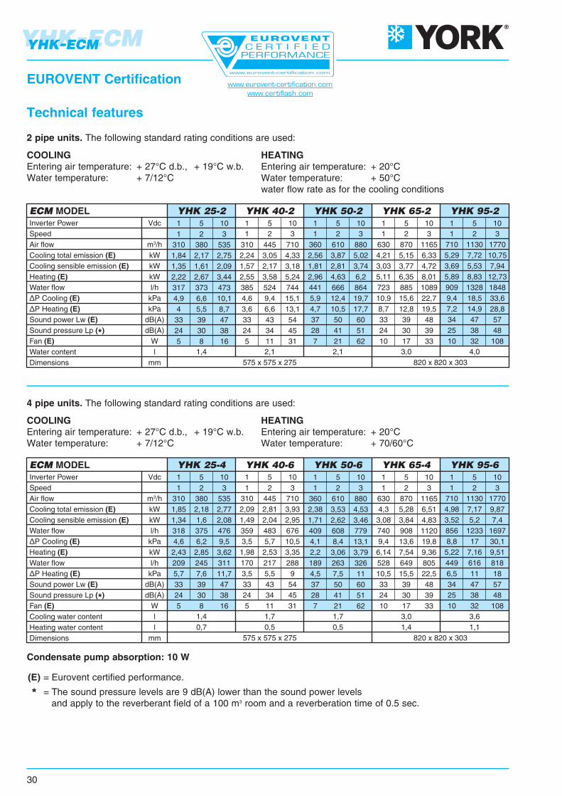
2 pipe units. The following standard rating conditions are used:
COOLINGEntering air temperature: + 27°C d.b., + 19°C w.b.Water temperature: + 7/12°C
HEATINGEntering air temperature: + 20°CWater temperature: + 50°Cwater flow rate as for the cooling conditions
4 pipe units. The following standard rating conditions are used:
COOLINGEntering air temperature: + 27°C d.b., + 19°C w.b.Water temperature: + 7/12°C
HEATINGEntering air temperature: + 20°CWater temperature: + 70/60°C
EUROVENT Certification
Technical features www.eurovent-certification.comwww.certiflash.com
Condensate pump absorption: 10 W

YHK25-2
YHK20-2
YHK40-2
YHK50-2
YHK65-2
YHK95-2
YHK110-2
38631023748241735678759341290370252011188657341683114687620151471876
2,241,801,382,802,422,074,573,452,395,254,083,026,505,034,279,786,675,0911,728,555,09
2031641262662321984403342355043942946244864159516555051132834505
2,371,911,463,102,692,315,123,892,735,864,583,427,265,654,8211,067,625,8713,179,705,87
298239183377327279619467326709552410878681578132790669415861161694
3,462,782,134,393,803,257,195,433,798,256,424,7710,217,926,7215,4310,548,0718,4513,508,07
39331524048842236079559841591470952411308747411699115588220371484882
4,563,662,805,684,914,199,256,964,8310,638,256,1013,1410,168,6119,7613,4310,2523,6817,2610,25
488391298599513441972730505111886663913831067903207114031068248618071068
5,674,553,476,975,965,1211,308,485,8713,0010,077,4316,0812,4110,5024,0816,3212,4228,9121,0112,42
6104203105204203107105003208806104301140820630150097071018201280710
HighMedLowHighMedLowHighMedLowHighMedLowHighMedLowHighMedLow
HighMedLow
Model SpeedAirflow
EWT 45 - LWT 40°C EWT 50 - LWT 40°C EWT 60 - LWT 50°C EWT 70 - LWT 60°C EWT 80 - LWT 70°C
l/hm3/h kW l/h kW l/h kW l/h kW l/h kW
Waterflow Emission
Waterflow Emission
Waterflow Emission
Waterflow Emission
Waterflow Emission
YHK25-2
YHK20-2
YHK40-2
YHK50-2
YHK65-2
YHK95-2
YHK110-2
HighMedLowHighMedLowHighMedLowHighMedLowHighMedLowHighMedLow
HighMedLow
EWT 5 - LWT 10°C EWT 7 - LWT 12°C EWT 9 - LWT 14°C EWT 12 - LWT 17°CWaterflow
Totalemission
Sensibleemission
Waterflow
Totalemission
Sensibleemission
Waterflow
Totalemission
Sensibleemission
Waterflow
Totalemission
Sensibleemission
Model SpeedAirflow
l/h kW kW l/h kW kW l/h kW kW l/h kW kWm3/h6104203105204203107105003208806104301140820630150097071018201280710
421346269554482417926715508104983563312641003858194313741070227717221070
2,452,011,573,222,802,425,384,152,956,104,853,687,355,834,9911,307,996,2213,2410,016,22
1,831,481,142,221,911,643,642,771,944,173,262,445,003,923,327,595,274,069,016,684,06
34028021946240331774557538786366750610608457221635116691319091454913
1,981,631,272,682,341,844,333,342,255,023,882,946,164,914,219,516,785,3111,108,455,31
1,641,321,012,041,751,353,182,391,573,742,812,084,593,583,036,484,483,468,256,093,71
254210165362317276617483349694559430840674580130193974015111162740
1,471,220,962,101,841,613,592,812,034,033,252,504,883,923,377,575,464,308,786,754,30
1,451,160,891,751,501,292,872,181,533,292,571,923,953,092,625,994,153,207,115,273,20
1991601232522201884203192254793762835734533848806124341044775434
1,160,930,711,471,281,092,441,861,312,792,191,653,332,632,235,123,562,526,074,512,52
1,160,930,711,471,281,092,441,861,312,792,191,653,332,632,235,123,562,526,074,512,52
7/12 °C10/15 °C14/18 °C
KKK
0,90,720,5
0,940,780,58
1,060,90,72
7/12 °C10/15 °C14/18 °C
KKK
0,820,560,35
0,890,630,41
1,110,820,52
Water (°C) Air (°C) 25-18 26-18.5 28-20 Water (°C) Air (°C) 25-18 26-18.5 28-20Total emission Sensible emission Note:
the correctionfactors are indicative,as they areaverage values.
Emission correction factors for different working conditions.Multiply the factors by the emission figures in the 7-12°C table above.
6
Cooling emission of 1 battery units (2 pipe installation)Entering air temperature: +27°C d.b. +19°C w.b.
Emission
Heating emission of 1 battery units (2 pipe installation)Entering air temperature: +20°C

YHK25-4
YHK20-4
YHK40-4
YHK50-4
YHK65-4
YHK95-4
YHK110-4
Model SpeedAirflow
EWT 45 - LWT 40°C EWT 50 - LWT 40°C EWT 60 - LWT 50°C EWT 70 - LWT 60°C EWT 80 - LWT 70°C
l/hm3/h kW l/h kW l/h kW l/h kW l/h kW
Waterflow Emission
Waterflow Emission
Waterflow Emission
Waterflow Emission
Waterflow Emission
2562151662832471963512771964023172477716095019296865471074845547
1,491,250,961,651,441,142,041,611,142,341,841,444,483,542,915,403,993,186,244,913,18
13411387149130103184146103211166130410324267493365291569449291
1,561,311,011,731,511,202,141,691,202,451,941,514,763,773,115,734,253,396,615,223,39
197166128218191151270214151310244191596471388718531423829653423
2,291,931,492,542,221,763,142,481,763,602,842,226,935,484,518,346,174,929,647,604,92
2612191692982602093782982094263412677836185089466975551092858555
3,032,541,963,463,022,434,403,462,434,953,973,109,107,195,9111,008,106,4512,709,986,45
325272210358312247444350247510401312970766629117086468613531064686
3,783,172,444,173,632,875,174,072,875,934,673,63
11,288,907,31
13,6010,047,98
15,7412,377,98
6104203105204203107105003208806104301140820630150097071018201280710
HighMedLowHighMedLowHighMedLowHighMedLowHighMedLowHighMedLow
HighMedLow
YHK25-4
YHK20-4
YHK40-4
YHK50-4
YHK65-4
YHK95-4
YHK110-4
HighMedLowHighMedLowHighMedLowHighMedLowHighMedLowHighMedLow
HighMedLow
490410314569465398718569398791632510129910278421588115892018361423920
2,852,381,823,312,712,314,183,312,314,603,672,977,555,974,899,236,735,3510,678,275,35
2,121,731,292,261,831,552,912,261,553,232,532,015,124,003,246,354,533,567,435,643,56
4013372604654053185744553186565204051090866713132797477815291191778
2,331,961,512,702,361,853,342,651,853,813,022,366,345,034,147,715,664,528,896,934,52
1,901,551,151,981,701,342,561,981,342,972,291,754,693,652,965,834,153,256,845,183,25
30726020137430926746737426751241333786469157210467756231199942623
1,781,511,172,181,801,552,722,181,552,982,401,965,024,023,336,084,503,626,975,483,62
1,691,371,021,791,441,222,301,791,222,562,001,594,043,152,565,023,572,815,984,462,81
2391961482602101773302601773662882315864623747,26524411849646411
1,391,140,861,511,221,031,921,511,032,131,671,353,412,682,174,223,052,394,943,752,39
1,391,140,861,511,221,031,921,511,032,131,671,353,412,682,174,223,052,394,943,752,39
6104203105204203107105003208806104301140820630150097071018201280710
EWT 5 - LWT 10°C EWT 7 - LWT 12°C EWT 9 - LWT 14°C EWT 12 - LWT 17°CWaterflow
Totalemission
Sensibleemission
Waterflow
Totalemission
Sensibleemission
Waterflow
Totalemission
Sensibleemission
Waterflow
Totalemission
Sensibleemission
Model SpeedAirflow
l/h kW kW l/h kW kW l/h kW kW l/h kW kWm3/h
7/12 °C10/15 °C14/18 °C
KKK
0,90,720,5
0,940,780,58
1,060,90,72
7/12 °C10/15 °C14/18 °C
KKK
0,820,560,35
0,890,630,41
1,110,820,52
Water (°C) Air (°C) 25-18 26-18.5 28-20 Water (°C) Air (°C) 25-18 26-18.5 28-20Total emission Sensible emission Note:
the correctionfactors are indicative,as they areaverage values.
7
Emission correction factors for different working conditions.Multiply the factors by the emission figures in the 7-12°C table above.
Cooling emission of 2 battery units (4 pipe installation)Entering air temperature: +27°C d.b. +19°C w.b.
Heating emission of 2 battery units (4 pipe installation)Entering air temperature: +20°C
Emission of 4 pipe unitswith standard cooling battery

K 0,94 0,90 0,86 0,82 0,78 0,74 0,70
20 30 40 50 60 70 80°C
K 0,94 0,90 0,86 0,82 0,78 0,74 0,70
20 30 40 50 60 70 80°CK 1,14 1,08 1,02 0,96 0,90
°C 40 50 60 70 80
Pre
ssur
e dr
op (
kPa)
Water flow (l/h)
Pre
ssur
e dr
op (
kPa)
Water flow (l/h)
Pre
ssur
e dr
op (
kPa)
Water flow (l/h)
Pressure drop for cooling battery Pressure drop for heating battery
2 pipe installation
4 pipe installation
8
Water side pressure drop
The water pressure drop figures refer to a mean water temperature of 10°C;for different temperatures, multiply the pressure drop figures by the correction factors K.
The water pressure drop figuresrefer to a mean water temperature of 65°C;
for different temperatures, multiplythe pressure drop figures by the correction factors K.
The water pressure drop figuresrefer to a mean water temperature of 10°C;
for different temperatures, multiplythe pressure drop figures by the correction factors K.

Water flow MAX. working pressure: 8 bars
MIN. entering water temperature: +5°C
MAX. entering water temperature: +80°C
Installation MAX. height: see table on page 12
Supply Single phase 230V / 50Hz
Air flow Suitable relative humidity: 15-75%
MIN. entering air temperature: +6°C
MAX. entering air temperature: +40°C
9
Working conditions

790 350 750 150
A B C Dmm
30 246 3
kg kg
Weightspacked unit
Weightsunpacked unit
YHK 20-2 / 25-2 YHK 20-4 / 25-4 YHK 40-2 / 40-4 YHK 50-2 / 50-4
28 22
UNIT DIFFUSER
kg kg
ModelWeights
packed unitWeights
unpacked unit
Packed unitDimensions
MD-600METAL DIFFUSER
(RS receiver, Code 9066338,for MD-600 metal diffuserfor MP units)
YHK 20/25/40/50-2YHK 20/25/40/50-4
10
Dimensions and weights
(Version 600 x 600)
2 pipe units- 3. Flow, heating/cooling 1/2”
- 4. Return, heating/cooling 1/2”
4 pipe units- 1. Flow, heating 1/2”- 2. Return, heating 1/2”- 3. Flow, cooling 1/2”- 4. Return, cooling 1/2”
Packed unitDimensions
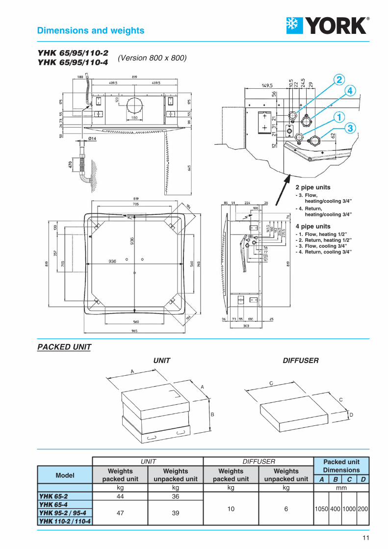
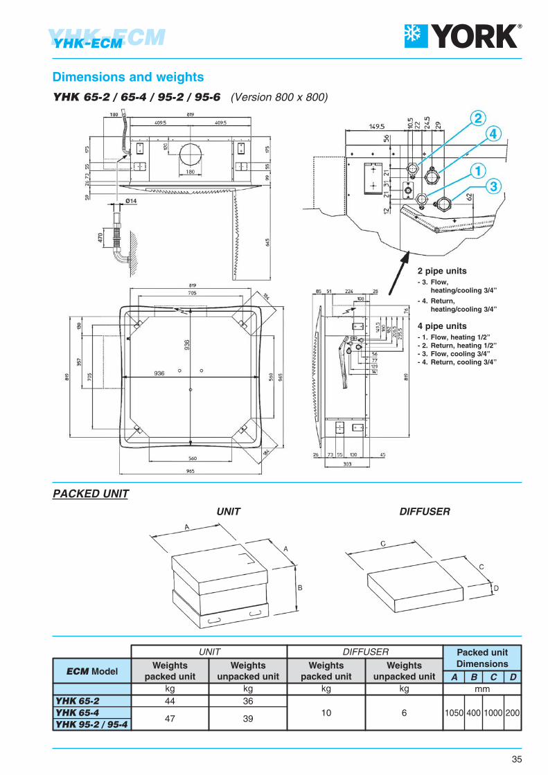
1050 400 1000 200
A B C Dmm
47 3910 6
kg kg
Weightspacked unit
Weightsunpacked unit
YHK 65-2 YHK 65-4 YHK 95-2 / 95-4 YHK 110-2 / 110-4
44 36
UNIT DIFFUSER
kg kg
ModelWeights
packed unitWeights
unpacked unit
UNIT DIFFUSER
PACKED UNIT
11
Dimensions and weights
YHK 65/95/110-2YHK 65/95/110-4 (Version 800 x 800)
2 pipe units- 3. Flow, heating/cooling 3/4”
- 4. Return, heating/cooling 3/4”
4 pipe units- 1. Flow, heating 1/2”- 2. Return, heating 1/2”- 3. Flow, cooling 3/4”- 4. Return, cooling 3/4”

1 2 3 1 2 3 1 2 3 1 2 3 1 2 3 1 2 33,32,22,5
3,92,62,9
4,22,83,1
3,32,22,5
4,22,83,1
4,83,23,6
3,92,62,9
4,53,03,4
5,23,43,9
3,52,22,7
4,12,63,2
4,83,03,8
3,82,43,0
4,62,83,6
5,43,44,2
3,82,43,0
5,13,14,0
5,83,64,6
SpeedAir throw L mHeight H mDistance B m
Model YHK 20/25 YHK 40 YHK 50 YHK 65 YHK 95 YHK 110
YHK 20/25 YHK 40 YHK 50 YHK 65 YHK 95 YHK 110SpeedAir throw L m
1 2 3 1 2 3 1 2 3 1 2 3 1 2 3 1 2 33,0 3,5 3,8 3,0 3,8 4,5 3,5 4,2 5,0 3,2 3,7 4,3 3,4 4,0 5,0 3,4 4,6 5,5
Model
NOTE:On heating it must be payed attention to rooms where the floor temperatureis particularly low (for example less than 5°C).In this situation the floor can cool the lower layer of air to a level that stopthe uniform diffusion of the hot air coming from the unit,decreasing the throw figures shown in the table.
The air throw indicated in the tables must only be considered the maximum value, as it maychange significantly in relation to the dimensions of the room in which the appliance is installedand the positioning of the furniture in the room.
The useful throw L refers to the distance between the unit and the point where the air speedis 0.2 m/sec; if the louver has a gradient of 30° (recommended in cooling mode), the so-called“Coanda” effect will occur, illustrated in the first figure, while at a gradient of 45° (recommendedin heating mode), there will be a downwards throw, as illustrated in the second figure.
With adjustableair diffusion louvers at 30°
12
Air throw
With adjustableair diffusion louvers at 45°

The cassette is fittedwith inlets for fresh air to be mixedwith return air inside the unit (Fig. 3).
The fresh air flow is limited to 20%of the total fan coil air flow at medium speedand 100 m3/h for each treated air inlet.
The units feature fresh air inletson three corners (no inlets on the fourth cornerbecause of the condensate pump inside the unit).
The fresh air inlets are designed for the insertion of standard 110 x 55 mm rectangular ducts.
The air duct is connected quickly and easily. After removing the blank and the insulation inside the unit,the mounting plate is rolled back and the air duct with its V-shaped sectionmust be pushed into the unit (see Figures below). The duct is then fixed to the mounting plate.
Note: the fresh air must be filtered.
Accessory “Fresh air connection” - Identification FAD - Code 6078005 (see page 14)
FRESH AIR INLET
AIR INTAKE
Fresh
air connection
MAINAIR INLET
AIR INTAKE
1 2 3 4
13
Fresh air supply - Fresh air connection
Spigot
for air distribution
AIR OUTLET
AIR INTAKE
Two air outlets are providedon the side of the unit for connectionto separate supply air outlets.
They can be used to supply air fromthe fan coil unit to distant areas of a roomor even to a different room.
The total air flow does not change.
The air flow at high speed dependingon the air duct pressure drop is shownin the tables below.
Note: all air ducts must be insulatedin order to avoid condensation.
Air distribution - Air distribution connection
No. used outlets = 1 No. used outlets = 2
Air flow (m3/h)
Air flow (m3/h)
Air flow (m3/h)
Air flow (m3/h)
Pre
ssur
e dr
op (
Pa)
Pre
ssur
e dr
op (
Pa)
Pre
ssur
e dr
op (
Pa)
Pre
ssur
e dr
op (
Pa)
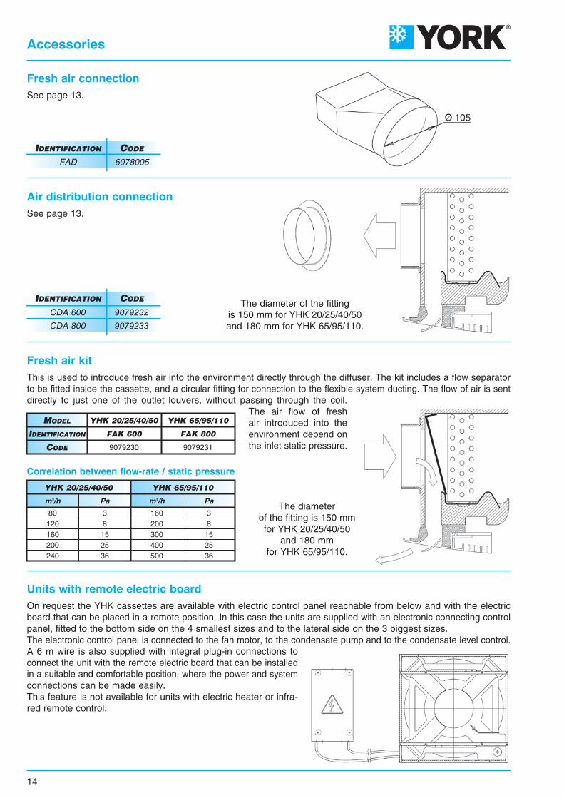
Fresh air kitThis is used to introduce fresh air into the environment directly through the diffuser. The kit includes a flow separatorto be fitted inside the cassette, and a circular fitting for connection to the flexible system ducting. The flow of air is sentdirectly to just one of the outlet louvers, without passing through the coil.
The air flow of freshair introduced into theenvironment depend onthe inlet static pressure.
The diameter of the fittingis 150 mm for YHK 20/25/40/50and 180 mm for YHK 65/95/110.
The diameterof the fitting is 150 mmfor YHK 20/25/40/50
and 180 mmfor YHK 65/95/110.
Units with remote electric boardOn request the YHK cassettes are available with electric control panel reachable from below and with the electricboard that can be placed in a remote position. In this case the units are supplied with an electronic connecting controlpanel, fitted to the bottom side on the 4 smallest sizes and to the lateral side on the 3 biggest sizes.The electronic control panel is connected to the fan motor, to the condensate pump and to the condensate level control.A 6 m wire is also supplied with integral plug-in connections toconnect the unit with the remote electric board that can be installedin a suitable and comfortable position, where the power and systemconnections can be made easily.This feature is not available for units with electric heater or infra-red remote control.
Fresh air connectionSee page 13.
Air distribution connectionSee page 13.
IDENTIFICATION CODE
FAD 6078005
CDA 800 9079233
CDA 600 9079232
IDENTIFICATION CODE
Correlation between flow-rate / static pressure
14
Accessories
FAK 800
YHK 65/95/110
9079231
FAK 600
YHK 20/25/40/50
9079230
IDENTIFICATION
MODEL
CODE
YHK 20/25/40/50 YHK 65/95/110
160200300400500
80120160200240
m3/hm3/h
38152536
38152536
PaPa

15
Accessories
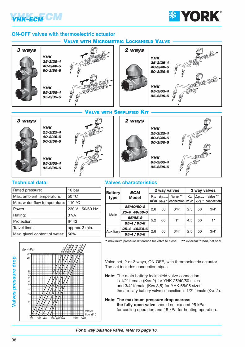
* maximum pressure difference for valve to close ** external thread, flat seal
Batterytype
Main
Model
Auxiliary
20/25/40/50-2
20/25/40/50-4
65/95/110-2
65/95/110-4
20/25/40/50-4
65/95/110-4
2 way valves 3 way valves
Kvs
m3/hpmax
kPa *Valve **
connectionKvs
m3/hpmax
kPa *Valve **
connection
2,8
5,2
2,8
50
60
50
3/4"
1"
3/4"
2,5
4,5
2,5
50
50
50
3/4"
1"
3/4"
Rated pressure:
Max. ambient temperature:
Max. water flow temperature:
Power:
Rating:
Protection:
Travel time:
Max. glycol content of water:
16 bar
50 °C
110 °C
230 V - 50/60 Hz
3 VA
IP 43
approx. 3 min.
50%
ON-OFF valves with thermoelectric actuator
Valve set, 2 or 3 ways, ON-OFF, with thermoelectric actuator.The set includes connection pipes.
Note: The main battery lockshield valve connection is 1/2” female (Kvs 2) for YHK 20/25/40/50 sizes and 3/4” female (Kvs 3,5) for YHK 65/95/110 sizes, the auxiliary battery valve connection is 1/2” female (Kvs 2).
Note: The maximum pressure drop accross the fully open valve should not exceed 25 kPa for cooling operation and 15 kPa for heating operation.
Technical data: Valves characteristics
3 ways 2 ways
Valves pressure drop
3 ways 2 ways
VALVE WITH MICROMETRIC LOCKSHIELD VALVE
VALVE WITH SIMPLIFIED KIT
Waterflow (l/h)
p - kPa

16
Accessories
• “p1” is the valve inlet pressure.• “p3” is the outlet pressure.• “p2” is the diaphragm activation pressure, which allows differential pressure “p2” – “p3” to be maintained at a constant value, in order to guarantee the water to flow at the set value.
The minimum differential pressure “p1” – ”p3”,required to guarantee the correct value of theset water flow rate, is indicated in the diagramson page 17. This is an essential factor to size thesystem pressure drop and pump pressure head.The flow rate is kept at a constant value only ifthe valve pressure drop is higher than the indicated value.
The minimum differential pressure and the balancing valve pressure drop must be considered to size the systempumps.Flow rate is constant if the pressure drop is higher than that indicated in the diagrams on page 17.The following diagram shows an example of the flow rate trend according to the pressure drop and calibrationrequired.
Example DN 15 Model
Balancing valves independent from the system pressure• The balancing valve and a combined 2 way valve allow the regulation of the water flow value autonomously, regardless of the system pressure, and the control of the flow by using an ON/OFF electro-thermal actuator.• The balancing valve allows you to balance the hydraulic system by supplying the required water flow, for each fan- coil, and to maintain it even under partial load conditions.• A graduated ring nut placed under the valve allows you to set the flow rate value and also allows direct reading of the set value.
Valve operation logic
Minimum operating differential pressure
LEGEND:
Qw = Water flow rate (l/h)
Pd = Min. differential pressure “p1” – ”p3” (bar)
Q1 = Area with inconstant water flow
Q2 = Area with constant water flow
S1 = Position of the adjustment valve plunger
M1 = Position of the knob

17
Accessories
Benefits
Operation limits of the balancing valves
Technical features
The valve upstream-downstream minimum differential pressure (“p1” – “p3”), which depends on the valve calibrationvalue, must be exceeded to access the constant flow rate field.
DN 20 ModelDN 15 Model
LEGEND:
Pd = Min. differential pressure “p1” – ”p3” (bar)
E.g., when sizing the system pump, in which the DN 15 valves will be installed and in which 450 l/h are constantly requiredfor each device, consider a useful pressure of 0.3 bar (to compensate the pressure drop of the valve) for each balancing valve.Therefore, the pressure drop values produced by the system balancing valves must be summed and the pump must be sizedto produce a pressure equal to or greater than the value obtained previously.
• Maximum operating temperature 120°C• Maximum operating pressure 16 bar• Maximum % of water/glycol mixture 50%
• Minimum operating temperature -10°C• Maximum differential pressure 4 bar
• Reduced dimensions.• Easy installation on 2 or 4 pipe devices.• Pre-regulation of the nominal value set even with installed actuator.• Easy display of the nominal value set. Nominal values are indicated in 10 l/h without any conversion.• Guarantee of constant flow rate set even with partial loads.• Pre-regulation can be blocked and leaded with the locking ring.
DN MODEL FLOW RATE RANGE (l/h) Kvs
DN 15DN 20
150 – 1050
180 – 1300
1,8
2,5
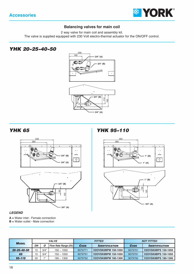
3/4” (A)
3/4” (A)
3/4” (B)
3/4” (B)
162258
113
150
1” (B)
1” (B)
3/4” (A)
1” (A)
360464
56
155
360449
60
155
3/4” (B)
3/4” (B)
3/4” (A)
3/4” (A)
18
Accessories
NOT FITTEDFITTEDVALVE
Flow Rate Range (l/h)DN Ø CODECODE IDENTIFICATIONIDENTIFICATION
150 – 1050
150 – 1050
180 – 1300
15
15
20
3/4”
3/4”
1”
9079761
9079781
9079782
9079771
9079791
9079792
V2OVSK6BPS 150-1050
V2OVSK8BPS 150-1050
V2OVSK8BPS 180-1300
V2OVSK6BPM 150-1050
V2OVSK8BPM 150-1050
V2OVSK8BPM 180-1300
MODEL
20–25–40–5065
95–110
YHK 20-25-40-50
YHK 65 YHK 95-110
Balancing valves for main coil2 way valve for main coil and assembly kit.
The valve is supplied equipped with 230 Volt electro-thermal actuator for the ON/OFF control.
LEGEND
A = Water inlet - Female connectionB = Water outlet - Male connection

162182
258
150
56
113
3/4” (A)
3/4” (C)
3/4” (D)
3/4” (C)
3/4” (B)
3/4” (A)
155
324360
446463
463
57
127
446
324360
446
6012
7
157
3/4” (C) 1” (C)
3/4” (A)
3/4” (D)
1” (B)
3/4” (A)
3/4” (B)
3/4” (D)
19
Accessories
NOT FITTEDFITTEDVALVE
Flow Rate Range (l/h)DN Ø CODECODE IDENTIFICATIONIDENTIFICATION
150 – 1050
150 – 1050
150 – 1050
150 – 1050
180 – 1300
15
15
15
15
20
3/4”
3/4”
3/4”
3/4”
1”
9079763
9079783
9079761
9079781
9079782
9079773
9079793
9079771
9079791
9079792
V2OVSK6BAS 150-1050
V2OVSK8BAS 150-1050
V2OVSK6BPS 150-1050
V2OVSK8BPS 150-1050
V2OVSK8BPS 180-1300
V2OVSK6BAM 150-1050
V2OVSK8BAM 150-1050
V2OVSK6BPM 150-1050
V2OVSK8BPM 150-1050
V2OVSK8BPM 180-1300
MODELCOIL
20–25–40–5065–95–110
20–25–40–5065
95–110
ADDITIONAL
MAIN
YHK 20-25-40-50
YHK 65 YHK 95-110
Balancing valves for main and additional coil2 way valve for additional coil and assembly kit.
The valve is supplied equipped with 230 Volt electro-thermal actuator for the ON/OFF control.
LEGEND
A = Water inlet (main coil) - Female connection C = Water inlet (additional coil) - Female connectionB = Water outlet (main coil) - Male connection D = Water outlet (additional coil) - Male connection
20
Wall electronic controls
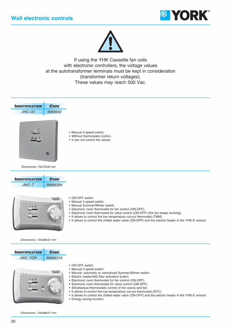
If using the YHK Cassette fan coilswith electronic controllers, the voltage values
at the autotransformer terminals must be kept in consideration(transformer return voltages).
These values may reach 500 Vac.
Dimensions: 135x86x31 mm
Dimensions: 75x75x30 mm
• ON-OFF switch.• Manual 3 speed switch.• Manual, automatic or centralized Summer/Winter switch.• Electric heater/IAQ filter activation button.• Electronic room thermostat for fan control (ON-OFF).• Electronic room thermostat for valve control (ON-OFF).• Simultaneus thermostatic control of the valves and fan.• It allows to control the low temperature cut-out thermostat (NTC).• It allows to control the chilled water valve (ON-OFF) and the electric heater in the YHK-E version.• Energy saving function.
IDENTIFICATION CODE
JWC-TQR 9066631K
• Manual 3 speed switch.• Without thermostatic control.• It can not control the valves.
IDENTIFICATION CODE
JWC-3V 9066642
Dimensions: 135x86x31 mm
• ON-OFF switch.• Manual 3 speed switch.• Manual Summer/Winter switch.• Electronic room thermostat for fan control (ON-OFF).• Electronic room thermostat for valve control (ON-OFF) (the fan keeps working).• It allows to control the low temperature cut-out thermostat (TMM).• It allows to control the chilled water valve (ON-OFF) and the electric heater in the YHK-E version.
IDENTIFICATION CODE
JWC-T 9066630K
21
Wall electronic controls
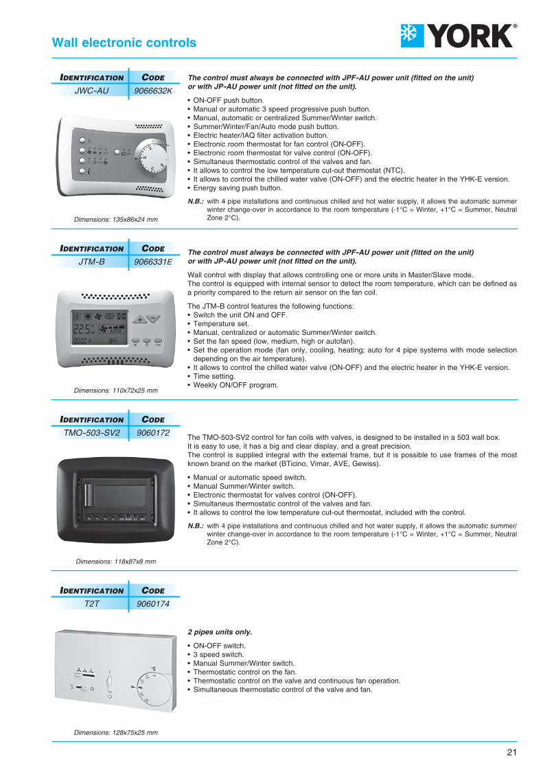
Dimensions: 128x75x25 mm
Dimensions: 110x72x25 mm
Dimensions: 118x87x8 mm
Dimensions: 135x86x24 mm
2 pipes units only.
• ON-OFF switch.• 3 speed switch.• Manual Summer/Winter switch.• Thermostatic control on the fan.• Thermostatic control on the valve and continuous fan operation.• Simultaneous thermostatic control of the valve and fan.
IDENTIFICATION CODE
T2T 9060174
The control must always be connected with JPF-AU power unit (fitted on the unit)or with JP-AU power unit (not fitted on the unit).
Wall control with display that allows controlling one or more units in Master/Slave mode.The control is equipped with internal sensor to detect the room temperature, which can be defined asa priority compared to the return air sensor on the fan coil.
The JTM-B control features the following functions:• Switch the unit ON and OFF.• Temperature set.• Manual, centralized or automatic Summer/Winter switch.• Set the fan speed (low, medium, high or autofan).• Set the operation mode (fan only, cooling, heating; auto for 4 pipe systems with mode selection depending on the air temperature).• It allows to control the chilled water valve (ON-OFF) and the electric heater in the YHK-E version.• Time setting.• Weekly ON/OFF program.
The TMO-503-SV2 control for fan coils with valves, is designed to be installed in a 503 wall box.It is easy to use, it has a big and clear display, and a great precision.The control is supplied integral with the external frame, but it is possible to use frames of the mostknown brand on the market (BTicino, Vimar, AVE, Gewiss).
• Manual or automatic speed switch.• Manual Summer/Winter switch.• Electronic thermostat for valves control (ON-OFF).• Simultaneus thermostatic control of the valves and fan.• It allows to control the low temperature cut-out thermostat, included with the control.
N.B.: with 4 pipe installations and continuous chilled and hot water supply, it allows the automatic summer/ winter change-over in accordance to the room temperature (-1°C = Winter, +1°C = Summer, Neutral Zone 2°C).
IDENTIFICATION CODE
JTM-B 9066331E
IDENTIFICATION CODE
TMO-503-SV2 9060172
The control must always be connected with JPF-AU power unit (fitted on the unit)or with JP-AU power unit (not fitted on the unit).
• ON-OFF push button.• Manual or automatic 3 speed progressive push button.• Manual, automatic or centralized Summer/Winter switch.• Summer/Winter/Fan/Auto mode push button.• Electric heater/IAQ filter activation button.• Electronic room thermostat for fan control (ON-OFF).• Electronic room thermostat for valve control (ON-OFF).• Simultaneus thermostatic control of the valves and fan.• It allows to control the low temperature cut-out thermostat (NTC).• It allows to control the chilled water valve (ON-OFF) and the electric heater in the YHK-E version.• Energy saving push button.
N.B.: with 4 pipe installations and continuous chilled and hot water supply, it allows the automatic summer winter change-over in accordance to the room temperature (-1°C = Winter, +1°C = Summer, Neutral Zone 2°C).
IDENTIFICATION CODE
JWC-AU 9066632K

22
Speed switches
• Speed switch (Slave).• It allows to control up to 8 units with only one centralized wall control (1 speed switch for each unit).• For controls JWC-T, JWC-TQR, and TMO-503-SV2.
Power unit to be installed on the fan coil (fan coil interface).
• It controls the fan and the valves of the fan coil.• It is connected to the electric supply.• It receives the information required from the control.
Control power absorption: 2,3 VA
IDENTIFICATION CODE
SEL2M 9079109
Power unit for JWC-AU and JTM-B remote control (fitted on the unit)
Power unit for JWC-AU and JTM-B remote control (not fitted on the unit)
DESCRIPTION
JPF-AU 9066641
JP-AU 9066640
IDENTIFICATION CODE

23
Wall electronic control accessories
BLACK
RED
BROWN
RED
NTC low temperature cut-out thermostat
TMM low temperature cut-out thermostat
Change-Over CH 15-25
T2 sensor
Suitable for wall controls only (not infra-red remote control). To be fitted between the coil fins;when connecting the control, the NTC probe cable must be separated from the power supply wires.To be used with JWC-TQR control and JP-AU power unit.It stops the fan when the water temperature is lower than 28°C and it starts the fan when is higher than 33°C.
To be installed in contact with the hot water circuit.To be used only with JWC-T control.For units working on heating only.It stops the fan when the water temperature is lower than 30°Cand it starts the fan when is higher than 38°C.
Suitable for wall controls only (not for infra-red remote control).Automatic summer/winter switchto be installed in contact with the water circuit.For 2-tube installations only (not to be used with 2 way valve).To be used only with JWC-TQR control.
T2 sensor to be placed on the water supply pipe upstream 3 way valves (not to be used with 2 way valve).The T2 sensor must be used as described below:• Change-Over for the automatic switch of the operating mode. If water temperature is lower than 20°C, cooling mode is set; on the other hand, if water temperature exceeds 30°C, heating mode is set.
To be used with JP-AU power unit.
IDENTIFICATION CODE
NTC 3021090
IDENTIFICATION CODE
TMM 9053048
IDENTIFICATION CODE
CH 15-25 9053049
IDENTIFICATION CODE
T2 9025310

24
Free wireless control system
Free
Free is an innovative, fully wireless, electronic system for use with fan coilunits, based on radio communication.
This technology provides installation flexibility and a more accuratemeasurement of the room temperature. The probe can be moved untilthe most suitable position is found, without the worry of changes in the roomlayout and of its furniture and also without mounting it on a wall. If a newfan coil unit is added, no electrical wiring for the control system is required:
just define the control unit and the probe which regulates it. The improved measurement accuracy is a result of thepossibility to position the probe near the user location: this enables to keep the temperature exactly at the requiredvalue with energy savings compared with a traditional measurement system.
Transmission is based on communication protocol IEE802.15.4, the most suitable way to transmit a relatively lowamount of information with very low consumption and high reliability.
The system has been certified by a leading independent body, officially recognized by the EU authorities and itssale has been authorized in all the EU and EFTA countries.
j t d fi th t l it d th b
Control unit with support
Power unit
Probe with support
A remote control which features a button panel andLCD display and can be wall-mounted or positionedon a dedicated table support.It enables the control of all the operating variables ofthe fan coil units in different configurations. The controlis battery powered.The temperature and the operating speed of the fancoil unit are set with two large buttons featuring userfriendly graphics.
A power unit to be installed on the fan coil (fan coilinterface).It controls the fan and the valves of the fan coil. Thepower unit is connected to the electric supply.The power unit receives the information required tocontrol the fan coil both from the remote control andlocally, such as the temperature of the coil.
A room temperature probe, which can be wallmounted or positioned on a dedicated table support.It is a battery powered device, able to measure the airtemperature in the spot where it is positioned, generatingtemperature information which is communicated to theother devices.
Main components
Free includes 3 main components:
Power unit fitted on the unit
Power unit not fitted on the unit
DESCRIPTION
Free-Usm 9079107
Free-Ups 9060570
IDENTIFICATION CODE
Temperature probe
DESCRIPTION
Free-Sen 9060573
IDENTIFICATION CODE
Remote control
DESCRIPTION
Free-Com 9060572
IDENTIFICATION CODE

25
Free wireless control system
The power unit controlsthe fan and the valves of the fan coil.The power unit receives the informationrequired to control such unitsboth from the remote control and locally.
This device is able to measurethe temperature of the air in the spotwhere it is positioned and to transmit itby means of radio communication tothe other devices in the system.It is battery powered and can befreely positioned in the area
to be air-conditioned.
On-off statusSummer operationWinter operationAutomatic season changeElectric heaterElectronic filterRoom temperature(with decimal accuracy)
Fan operating speedRequired/measured temperatureTimerClockTransmission signalBattery level
Fan coil on/off switching Fan speed selection (high - medium - low - automatic) Summer/winter operation selection Valve on/off Real time clock setting Temperature setting Daily switch on/off setting (timer function) Enable/disable the timer function Activation of the (eventual) electronic filter Activation of the (eventual) electric heater
The control enables:
Main features of the remote control
Main information displayed:
Main features of the power unit to be installed on the fan coil
Main features of the temperature probe
12 10 11 138
1 2 3 7 4 5 6
9
1
2
3
4
5
6
7
8
9
10
11
12
13
Fan on/off at a set speed Fan speed change (fan on/off) Water valve/s on/off (1 valve for 2 tube system - 2 valves for 4 tube system)
Fan speed change operating the water valve/s Control of the electric heater as main heating unit or as integration to the battery supplied with hot water Control of the operation of the electronic filter (in parallel to the fan)
Management of the dead zone function for 4-tube systems Available functional inputs: • Consent for remote on/off • Consent for remote Summer/Winter switch (centralized)
• Consent for the activation of the Energy Saving function with setting change • Minimum probe • Probe for season change
It enables the following main actions:
Measured environment temperature Transmission signal Clock Battery status
Display:
Tht
It enables the follo
T
It enables the fol
Tt
t
T

26
RT03 infra-red remote control
PSM-DI multifunction control
JTM-B wall control
All the controls for the ECM version and their functionsare described in detail from Page 44.
All the YHKY units can be supplied in MP version. This version includesa wide range of controls, including the infra-red remote control, which allows managing one single unit
or several units by using the Modbus RTU - RS 485 communication protocol.
Units can be managed according to the Master/Slave logic (up to 20 units)or by supervisory components.
The system consists in a MP board (mounted on models YHKY–MP and YHKY–ECM–MP)and a series of controls, such as the JTM-B wall control, the RT03 infra-red remote control,
the PSM-DI multifunction control and the NET supervisory program.
Controls and units for YHKY–MP versions
NET software
NET screenshot
PC

Model
Emission
Supply
Numberand Dia. of connecting wires
YHK 25-2-E YHK 65-2-E / 95-2-E / 110-2-E
1500 Watt
230V ~
3 x 1,5 mm2
YHK 40-2-E / 50-2-E
2500 Watt
230V ~
3 x 2,5 mm2
3000 Watt
230V ~
3 x 2,5 mm2
RD BK
OG
NL1M9
M8
M10
L1
L3
M11L1
R2
R1
M12
N
L2
L1N
L2N
L3N
Q2
R3TS1
M6
ThermostatALARM
High-levelALARM
7654
15141312111098
M7 J1
M3
TS2
WH
OG
BN
E
2
N21
M15
V1
V3V2M4
V2V3
V1J3 J5
J2
M5J4
21
L
EH3
1
5 4 3
B1
WH
WH
BN
BU
BU
BN
BK
BK
BK
SEC1
..M9
. MM M.C1 . L
1
.
T1
L
Q1
NPE
27
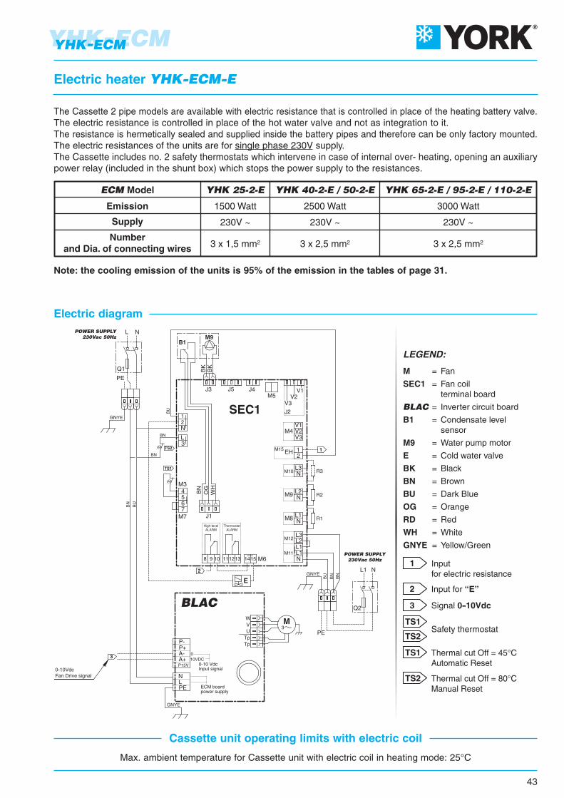
Electric heater YHK-E
The Cassette 2 pipe models are available with electric resistance that is controlled in place of the heating battery valve.The electric resistance is controlled in place of the hot water valve and not as integration to it.The resistance is hermetically sealed and supplied inside the battery pipes and therefore can be only factory mounted.The electric resistances of the units are for single phase 230V supply.The Cassette includes no. 2 safety thermostats which intervene in case of internal over- heating, opening an auxiliarypower relay (included in the shunt box) which stops the power supply to the resistances.
Note: the cooling emission of the units is 95% of the emission in the tables of page 6.
Max. ambient temperature for Cassette unit with electric coil in heating mode: 25°C
Cassette unit operating limits with electric coil
Electric diagram
Thermal cut Off = 45°C Automatic ResetTS1
Thermal cut Off = 80°C Manual ResetTS2Safety thermostat
POWER SUPPLY230Vac 50Hz
TS1
TS2Safet
TS1
TS2
LEGEND:
M = Fan
SEC1 = Fan coil terminal board
T1 = Autotransformer
C1 = Capacitor
B1 = Condensate level sensor
M9 = Water pump motor
S1 = Alarm condensate contact
E = Cold water valve
BK = Black
BN = Brown
BU = Dark Blue
OG = Orange
RD = Red
WH = White
R1-R2-R3 = Resistance
Q1-Q2 = Two poles disconnector
Inputfor electric resistance
1
Input for “E”2
Low speed
Medium speed
High speed
3
4
5
POWER SUPPLY230Vac 50Hz

The YHK-ECM series uses an innovative brushless synchronous permanent magnet electricmotor controlled by an inverter card that is directly installed on the unit.
The air flow can be varied continuously with of a 1-10 V signal from JCI controls or byindependent contollers (programmable controllers with a 1-10 V output).
The extreme efficiency, also at a low speed, makes possible a great reduction in electricconsumption (more than 75% less in comparison to a traditional motor) with absorptionvalues, under normal operating conditions, that are no greater than 10 Watt in the entire range.
The brushless motor is characterised by a constant synchronous speed, independently of theapplied load, that depends only on the motor power supply frequency, which is modulated bythe inverter. It consumes less because:
• The motor always works at its point of maximum efficiency.
• In the brushless motor, the rotor’s permanent magnets generate the magnetising power autonomously.
• The motor always operates at the synchronous speed, as a result there are no induced currents that reduce efficiency.
The main advantages are:
• Large reduction in energy consumption, thanks to an optimal response to the thermal load of the environment during every moment of the day.
• Operating silence at all rotation speeds.
• Ability to operate at any rotation speed.
Introduction
YHK-ECM
28
YHK-ECM
= YHK = YHK–ECM
MOTOR ABSORPTION
INTAKE GRID AND DISTRIBUTION OF THE AIRIntake grids, frame and adjustable air distribution louvers on each side, made from ABS.AKPA version : white ABS, RAL 9003AKPB version : with intake grid, frame and louvers, choice of one colour onlyAKPC version : with intake grid and louvers, choice of one colour, plus white ABS frame RAL 9003AKPD version : with louvers, choice of one colour, while the grid and frame are made from ABS, RAL 9003MD-600 version : metal diffuser painted in RAL 9003 white colour with 600x600 dimension to perfectly fit into the false ceiling standard modules without overlapping parts (800x800 model is not available).
CASINGIs made from galvanized steel with internal thermal insulation with polyolefin (PO) foam (class M1) andexternal anti-condensate lining.
CONTROL EQUIPMENTYHKY-ECM version It consists of the pump control circuit board and the inverter circuit board.
YHKY-ECM-MP version It consists of the MP electronic board (that integrates pump control) and the inverter board.
FAN ASSEMBLYThe fan assembly, which is mounted on anti-vibrating supports, is extremely silent.The radial fan has been designed to optimise performance, using wing profile blades with a shape thatreduces turbulence, increasing efficiency and reducing noise.The fans are connected to a three phase permanent magnet brushless electronic motor that is controlledwith reconstructed current according to a BLAC sinusoidal wave.The inverter board that controls the motor operation is powered by 230 Volt, single-phase and, with aswitching system, it generates a three-phase frequency modulated, wave form power supply.The electric power supply required for the machine is therefore single-phase with voltage of 230 - 240 Vand frequency of 50 - 60 Hz.
COILMade of copper tubes with bonded aluminium fins for maximum transfer contact.The coil has 2 or 3 rows for 2 pipe models and 2+1 rows for 4 pipe models (the heating row is on theinside part of the coil).For 4 pipe systems two versions are available:YHK 25-4 and YHK 65-4 supply an higher heating emission;YHK 40-6, YHK 50-6, YHK 95-6 supply an higher cooling emission.The heat exchanger is not suitable for use in corrosive atmosphere or in environments where aluminiummay be subject to corrosion.
CONDENSATE COLLECTION TRAYHigh density ABS polystyrene foam condensate tray, shaped in order to optimize the air diffusion, fireretardant rating B1 to DIN 4102.
AIR FILTERSynthetic washable filter, easily removable.
CONDENSATE PUMPFloat switch centrifugal pump with 650 mm of maximum head, integral to the unit and wired to the controlpanel on the outside of the casing.
VALVE SETTwo or three way valves for ON/OFF operation, with pipe mounting kit and thermostatic actuator.
29
YHK-ECMYHK-ECM
Main components
1,13,6
1,43,0
0,51,7
0,51,7
0,71,4
Inverter Power VdcSpeedAir flow m3/hCooling total emission (E) kWCooling sensible emission (E) kWWater flow l/h
P Cooling (E) kPaHeating (E) kWWater flow l/h
P Heating (E) kPaSound power Lw (E) dB(A)Sound pressure Lp (*) dB(A)Fan (E) WCooling water content lHeating water content lDimensions mm 820 x 820 x 303575 x 575 x 275
7104,983,528568,85,224496,5342510
11307,175,2
123317
7,1661611473832
17709,877,4
169730,19,51818185748
108
6304,33,087409,46,1452810,5332410
8705,283,8490813,67,5464915,5393017
11656,514,83112019,89,3680522,5483933
3602,381,714094,12,21894,537287
6103,532,626088,43,062637,5504121
8804,533,4677913,13,7932611605162
1 5 101 5 101 5 10
ECM MODEL YHK 25-4 YHK 40-6 YHK 50-6 YHK 65-4 YHK 95-6
3102,091,493593,51,981703,533245
4452,812,044835,72,532175,5433411
7103,932,9567610,53,35288
9544531
1 5 10
3101,851,343184,62,432095,733245
3802,181,63756,22,852457,639308
5352,772,084769,53,6231111,7473816
1 5 101 2 31 2 31 2 31 2 31 2 3
3,0 4,01,4 2,1 2,1820 x 820 x 303575 x 575 x 275
Inverter Power VdcSpeedAir flow m3/hCooling total emission (E) kWCooling sensible emission (E) kWHeating (E) kWWater flow l/h
P Cooling (E) kPaP Heating (E) kPa
Sound power Lw (E) dB(A)Sound pressure Lp (*) dB(A)Fan (E) WWater content lDimensions mm
1 2 31 2 31 2 3
ECM MODEL YHK 25-2 YHK 40-2 YHK 50-2 YHK 65-2 YHK 95-2
1 2 37105,293,695,899099,47,2342510
11307,725,538,83132818,514,9473832
177010,757,94
12,73184833,628,85748
108
6304,213,035,1172310,98,7332410
8705,153,776,3588515,612,8393017
11656,334,728,01108922,719,5483933
3602,561,812,964415,94,737287
6103,872,814,6366612,410,5504121
8805,023,746,286419,717,7605162
3102,241,572,553854,63,633245
4453,052,173,585249,46,6433411
7104,333,185,2474415,113,1544531
3101,841,352,223174,9433245
3802,171,612,673736,65,539308
5352,752,093,4447310,18,7473816
1 2 31 5 101 5 101 5 101 5 101 5 10
30
2 pipe units. The following standard rating conditions are used:
COOLINGEntering air temperature: + 27°C d.b., + 19°C w.b.Water temperature: + 7/12°C
HEATINGEntering air temperature: + 20°CWater temperature: + 50°Cwater flow rate as for the cooling conditions
Technical features
4 pipe units. The following standard rating conditions are used:
COOLINGEntering air temperature: + 27°C d.b., + 19°C w.b.Water temperature: + 7/12°C
HEATINGEntering air temperature: + 20°CWater temperature: + 70/60°C
YHK-ECMYHK-ECM
EUROVENT Certification www.eurovent-certification.comwww.certiflash.com
Condensate pump absorption: 10 W
(E) = Eurovent certified performance.
* = The sound pressure levels are 9 dB(A) lower than the sound power levels and apply to the reverberant field of a 100 m3 room and a reverberation time of 0.5 sec.
YHK25-2
YHK40-2
YHK50-2
YHK65-2
YHK95-2
EWT 45 - LWT 40°C EWT 50 - LWT 40°C EWT 55 - LWT 45°C EWT 60 - LWT 50°C EWT 70 - LWT 60°CWaterflow
l/h
Emission
kW
Waterflow
l/h
Emission
kW
Waterflow
l/h
Emission
kW
Waterflow
l/h
Emission
kW
Waterflow
l/h
Emission
kW
493383318749512365886663423115291273418171262842
2,872,221,854,362,982,125,153,852,466,705,304,2710,567,344,90
2722131784202902094943732416425124151015713481
3,172,482,074,893,382,435,754,342,817,475,954,8211,818,295,60
3302572145053472495954482887746154971222854574
3,832,992,495,874,042,906,925,203,359,007,155,7814,219,936,67
3873002505894042896965223359047175781428994666
4,493,492,916,854,703,368,096,073,8910,518,346,7216,6011,567,74
500387322758517368896670427116592274118371274849
5,824,513,758,816,014,2810,427,794,9613,5410,728,6121,3714,829,87
Speed VdcAirflow
m3/h
535380310710445310880610360116587063017701130710
10511051105110511051
High
Med
Low
High
Med
Low
High
Med
Low
High
Med
Low
High
Med
Low
ECMMod.
YHK25-2
YHK40-2
YHK50-2
YHK65-2
YHK95-2
EWT 5 - LWT 10°C EWT 7 - LWT 12°C EWT 9 - LWT 14°C EWT 12 - LWT 17°CSpeed Vdc
Airflow Water
flowTotal
emissionSensibleemission
l/h kW kW
Waterflow
Totalemission
Sensibleemission
l/h kW kW
Waterflow
Totalemission
Sensibleemission
l/h kW kW
Waterflow
Totalemission
Sensibleemission
l/h kW kWm3/h
570448379888621453103579352013041055859221015741068
3,322,602,25,173,612,636,024,613,027,586,134,9912,859,156,21
2,331,801,513,552,431,754,183,152,025,274,213,398,886,184,12
473373317744524385864666441108988572318481328909
2,752,171,844,333,052,245,023,872,566,335,154,2110,757,725,29
2,091,611,353,182,171,573,742,811,814,723,773,037,945,533,69
36829325058841931167852835485770157614561059734
2,141,701,453,422,431,813,943,072,064,984,073,358,476,164,27
1,841,421,182,801,911,383,302,481,594,173,322,677,004,863,24
2662071744102812044823632356044833921031718482
1,541,211,012,381,631,182,802,111,373,512,812,285,994,182,80
1,541,211,012,381,631,182,802,111,373,512,812,285,994,182,80
535380310710445310880610360116587063017701130710
10511051105110511051
High
Med
Low
High
Med
Low
High
Med
Low
High
Med
Low
High
Med
Low
ECMMod.
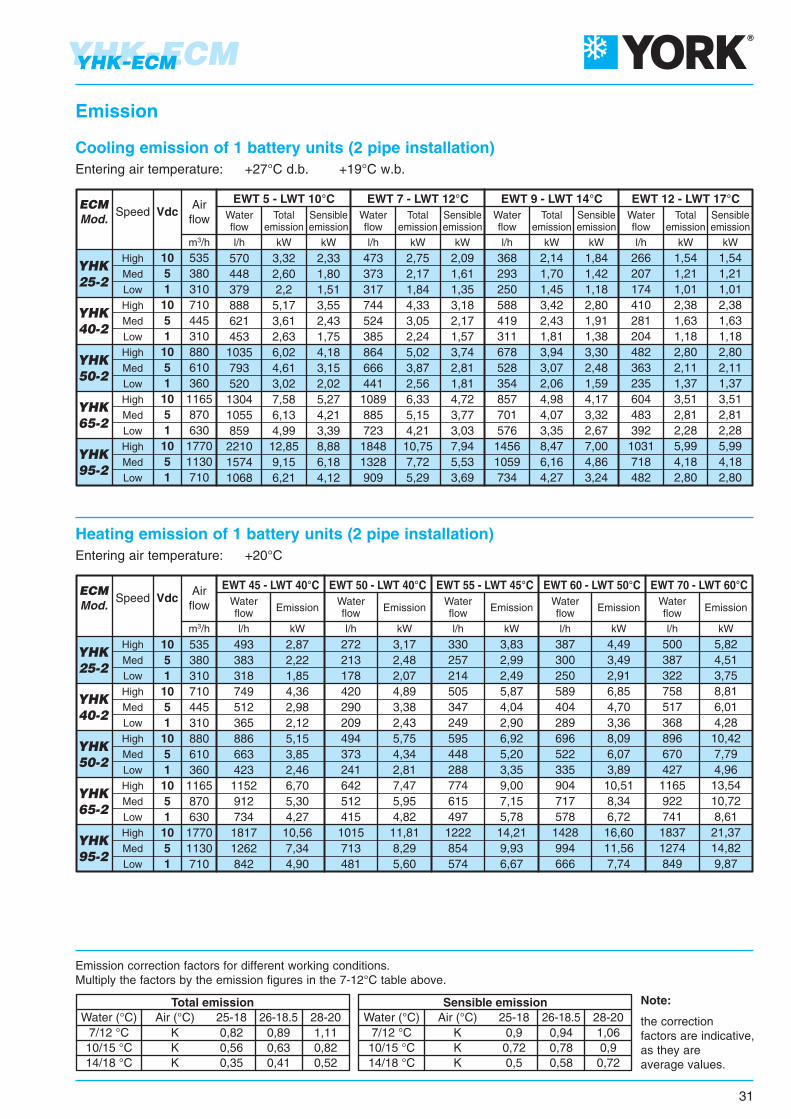
7/12 °C10/15 °C14/18 °C
KKK
0,90,720,5
0,940,780,58
1,060,90,72
7/12 °C10/15 °C14/18 °C
KKK
0,820,560,35
0,890,630,41
1,110,820,52
Water (°C) Air (°C) 25-18 26-18.5 28-20 Water (°C) Air (°C) 25-18 26-18.5 28-20Total emission Sensible emission Note:
the correctionfactors are indicative,as they areaverage values.
Emission correction factors for different working conditions.Multiply the factors by the emission figures in the 7-12°C table above.
31
YHK-ECMYHK-ECM
Emission
Cooling emission of 1 battery units (2 pipe installation)Entering air temperature: +27°C d.b. +19°C w.b.
Heating emission of 1 battery units (2 pipe installation)Entering air temperature: +20°C

YHK25-4
YHK40-6
YHK50-6
YHK65-4
YHK95-6
EWT 5 - LWT 10°C EWT 7 - LWT 12°C EWT 9 - LWT 14°C EWT 12 - LWT 17°CWaterflow
Totalemission
Sensibleemission
l/h kW kW
Waterflow
Totalemission
Sensibleemission
l/h kW kW
Waterflow
Totalemission
Sensibleemission
l/h kW kW
Waterflow
Totalemission
Sensibleemission
l/h kW kW
57244837881257642594072948613411081877203514671010
3,322,612,204,723,352,475,464,242,827,796,295,1011,838,535,87
2,321,791,503,292,281,663,862,931,915,404,303,458,265,823,93
476375318676483359779608409112090874016971233856
2,772,181,853,932,812,094,533,532,386,515,284,309,877,174,98
2,081,601,342,952,041,493,462,621,714,833,843,087,405,203,52
3722962525283822876064773258827195901332979687
2,171,721,463,072,221,673,522,771,895,134,183,437,745,693,99
1,831,411,182,601,791,313,052,311,504,263,382,716,534,583,09
264206172378262192442337221619497398951672457
1,541,201,002,201,531,122,571,961,293,62,892,325,533,902,66
1,541,201,002,201,531,122,571,961,293,62,892,325,533,902,66
Speed VdcAirflow
m3/h
535380310710445310880610360116587063017701130710
10511051105110511051
High
Med
Low
High
Med
Low
High
Med
Low
High
Med
Low
High
Med
Low
ECMMod.
YHK25-4
YHK40-6
YHK50-6
YHK65-4
YHK95-6
EWT 45 - LWT 40°C EWT 50 - LWT 40°C EWT 55 - LWT 45°C EWT 60 - LWT 50°C EWT 70 - LWT 60°CWaterflow
l/h
Emission
kW
Waterflow
l/h
Emission
kW
Waterflow
l/h
Emission
kW
Waterflow
l/h
Emission
kW
Waterflow
l/h
Emission
kW
305241205279211165315255184793639521800603440
1,781,401,191,621,230,961,831,481,074,613,723,034,653,502,56
1611271081391068315612793421340278413312229
1,871,481,261,611,230,971,821,481,084,903,963,234,803,632,67
198156133176133105198161117517417340514388284
2,301,821,552,041,551,222,311,871,366,014,853,965,974,513,30
236186158213161127241195141613494403615464339
2,742,161,842,481,871,472,802,271,647,135,754,687,155,393,94
311245209288217170326263189805649528818616449
3,622,852,433,352,531,983,793,062,209,367,546,149,517,165,22
Speed VdcAirflow
m3/h
535380310710445310880610360116587063017701130710
10511051105110511051
High
Med
Low
High
Med
Low
High
Med
Low
High
Med
Low
High
Med
Low
ECMMod.
7/12 °C10/15 °C14/18 °C
KKK
0,90,720,5
0,940,780,58
1,060,90,72
7/12 °C10/15 °C14/18 °C
KKK
0,820,560,35
0,890,630,41
1,110,820,52
Water (°C) Air (°C) 25-18 26-18.5 28-20 Water (°C) Air (°C) 25-18 26-18.5 28-20Total emission Sensible emission Note:
the correctionfactors are indicative,as they areaverage values.
Emission of 4 pipe unitswith standard and enhanced cooling battery
Emission correction factors for different working conditions.Multiply the factors by the emission figures in the 7-12°C table above.
YHK-ECM
32
YHK-ECM
Cooling emission of 2 battery units (4 pipe installation)Entering air temperature: +27°C d.b. +19°C w.b.
Heating emission of 2 battery units (4 pipe installation)Entering air temperature: +20°C
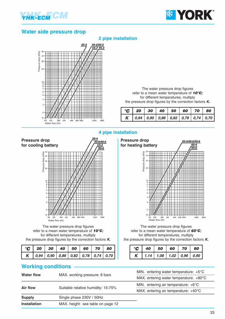
Installation MAX. height: see table on page 12
Supply Single phase 230V / 50Hz
Air flow Suitable relative humidity: 15-75%MIN. entering air temperature: +6°C
MAX. entering air temperature: +40°C
Water flow MAX. working pressure: 8 barsMIN. entering water temperature: +5°C
MAX. entering water temperature: +80°C
Pre
ssur
e dr
op (
kPa)
Water flow (l/h)
Pre
ssur
e dr
op (
kPa)
Water flow (l/h)
Pre
ssur
e dr
op (
kPa)
Water flow (l/h)
K 0,94 0,90 0,86 0,82 0,78 0,74 0,70
20 30 40 50 60 70 80°CK 1,14 1,08 1,02 0,96 0,90
°C 40 50 60 70 80
K 0,94 0,90 0,86 0,82 0,78 0,74 0,70
20 30 40 50 60 70 80°C
Working conditions
The water pressure drop figuresrefer to a mean water temperature of 10°C;
for different temperatures, multiplythe pressure drop figures by the correction factors K.
Pressure dropfor cooling battery
Pressure dropfor heating battery
2 pipe installation
4 pipe installation
33
YHK-ECMYHK-ECM
Water side pressure drop
The water pressure drop figuresrefer to a mean water temperature of 65°C;
for different temperatures, multiplythe pressure drop figures by the correction factors K.
The water pressure drop figuresrefer to a mean water temperature of 10°C;
for different temperatures, multiplythe pressure drop figures by the correction factors K.
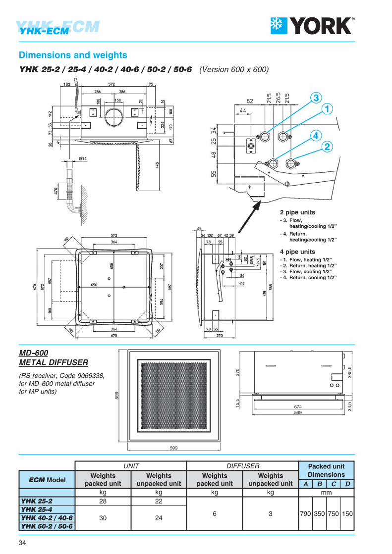
790 350 750 150
A B C Dmm
30 246 3
kg kg
Weightspacked unit
Weightsunpacked unit
YHK 25-2 YHK 25-4 YHK 40-2 / 40-6 YHK 50-2 / 50-6
28 22
UNIT DIFFUSER
kg kg
ECM ModelWeights
packed unitWeights
unpacked unit
Packed unitDimensions
2 pipe units- 3. Flow, heating/cooling 1/2”
- 4. Return, heating/cooling 1/2”
4 pipe units- 1. Flow, heating 1/2”- 2. Return, heating 1/2”- 3. Flow, cooling 1/2”- 4. Return, cooling 1/2”
YHK 25-2 / 25-4 / 40-2 / 40-6 / 50-2 / 50-6 (Version 600 x 600)
YHK-ECM
34
YHK-ECM
Dimensions and weights
MD-600METAL DIFFUSER
(RS receiver, Code 9066338,for MD-600 metal diffuserfor MP units)
1050 400 1000 20010 6
Packed unitDimensions
A B C Dmm
47 39
kg kg
Weightspacked unit
Weightsunpacked unit
YHK 65-2 YHK 65-4 YHK 95-2 / 95-4
44 36
UNIT DIFFUSER
kg kg
ECM ModelWeights
packed unitWeights
unpacked unit
2 pipe units- 3. Flow, heating/cooling 3/4”
- 4. Return, heating/cooling 3/4”
4 pipe units- 1. Flow, heating 1/2”- 2. Return, heating 1/2”- 3. Flow, cooling 3/4”- 4. Return, cooling 3/4”
PACKED UNIT
YHK 65-2 / 65-4 / 95-2 / 95-6 (Version 800 x 800)
35
YHK-ECMYHK-ECM
Dimensions and weights
UNIT DIFFUSER

YHK 25 YHK 40 YHK 50 YHK 65 YHK 951 2 3
3,32,22,5
3,92,62,9
4,22,83,1
1 2 33,32,22,5
4,22,83,1
4,83,23,6
1 2 33,92,62,9
4,53,03,4
5,23,43,9
1 2 33,52,22,7
4,12,63,2
4,83,03,8
1 2 33,82,43,0
4,62,83,6
5,43,44,2
SpeedAir throw L mHeight H mDistance B m
ECM Model
YHK 25 YHK 40 YHK 50 YHK 65 YHK 951 2 3
3,0 3,5 3,81 2 3
3,0 3,8 4,51 2 3
3,5 4,2 5,01 2 3
3,2 3,7 4,31 2 3
3,4 4,0 5,0SpeedAir throw L m
ECM Model
With adjustableair diffusion louvers at 30°
With adjustableair diffusion louvers at 45°
NOTE: On heating it must be payed attention to rooms where the floor temperature is particularly low (for example less than 5°C). In this situation the floor can cool the lower layer of air to a level that stop the uniform diffusion of the hot air coming from the unit, decreasing the throw figures shown in the table.
The air throw indicated in the tables must only be considered the maximum value, as it maychange significantly in relation to the dimensions of the room in which the appliance is installedand the positioning of the furniture in the room.
The useful throw L refers to the distance between the unit and the point where the air speedis 0.2 m/sec; if the louver has a gradient of 30° (recommended in cooling mode), the so-called“Coanda” effect will occur, illustrated in the first figure, while at a gradient of 45° (recommendedin heating mode), there will be a downwards throw, as illustrated in the second figure.
YHK-ECM
36
YHK-ECM
Air throw

37
YHK-ECMYHK-ECM
Accessories
Fresh air kitThis is used to introduce primary air into the environment directly through the diffuser. The kit includes a flow separatorto be fitted inside the cassette, and a circular fitting for connection to the flexible system ducting. The flow of air is sentdirectly to just one of the outlet louvers, without passing through the coil.
The air flow of freshair introduced into theenvironment depend onthe inlet static pressure.
The diameter of the fittingis 150 mm for YHK 25/40/50and 180 mm for YHK 65/95.
The diameterof the fitting is 150 mm
for YHK 25/40/50and 180 mm for YHK 65/95.
Fresh air connectionSee page 13.
Air distribution connectionSee page 13.
IDENTIFICATION CODE
FAD 6078005
CDA 800 9079233
CDA 600 9079232
IDENTIFICATION CODE
Correlation between flow-rate / static pressure
FAK 800
YHK 65/95
9079231
FAK 600
YHK 25/40/50
9079230
IDENTIFICATION
MODEL
CODE
YHK 25/40/50 YHK 65/95
160200300400500
80120160200240
m3/hm3/h
38152536
38152536
PaPa
For 2 way balance valve, refer to page 16.
38
Valve set, 2 or 3 ways, ON-OFF, with thermoelectric actuator.The set includes connection pipes.
Note: The main battery lockshield valve connection is 1/2” female (Kvs 2) for YHK 25/40/50 sizes and 3/4” female (Kvs 3,5) for YHK 65/95 sizes, the auxiliary battery valve connection is 1/2” female (Kvs 2).
Note: The maximum pressure drop accross the fully open valve should not exceed 25 kPa for cooling operation and 15 kPa for heating operation.
Val
ves
pre
ssu
re d
rop
ON-OFF valves with thermoelectric actuator
3 ways 2 ways
3 ways 2 ways
Batterytype
Main
ECMModel
Auxiliary
25/40/50-2
25-4 40/50-6
65/95-2
65-4 / 95-6
25-4 40/50-6
65-4 / 95-6
2 way valves 3 way valves
Kvs
m3/hpmax
kPa *Valve **
connectionKvs
m3/hpmax
kPa *Valve **
connection
2,8
5,2
2,8
50
60
50
3/4"
1"
3/4"
2,5
4,5
2,5
50
50
50
3/4"
1"
3/4"
* maximum pressure difference for valve to close ** external thread, flat seal
Rated pressure:
Max. ambient temperature:
Max. water flow temperature:
Power:
Rating:
Protection:
Travel time:
Max. glycol content of water:
16 bar
50 °C
110 °C
230 V - 50/60 Hz
3 VA
IP 43
approx. 3 min.
50%
Technical data: Valves characteristics
VALVE WITH MICROMETRIC LOCKSHIELD VALVE
VALVE WITH SIMPLIFIED KIT
YHK-ECMYHK-ECM
Waterflow (l/h)
p - kPa

LEGEND
SEP = Pump control boardBLAC = Inverter board
M = Electronic motorCONTROLLER = Controller
39
YHK-ECMYHK-ECM
For this cassette configuration, the 1-10 Vdc signal, which controls the inverter, must be suppliedby a controller with the following signal specifications:
• Impedance < 100 Ω;
• Maximum speed 10Vdc;
• Fan OFF with V < 0.9Vdc.
YHKY–ECM configuration
YHKY–ECM electric diagram
40
YHK-ECMYHK-ECM
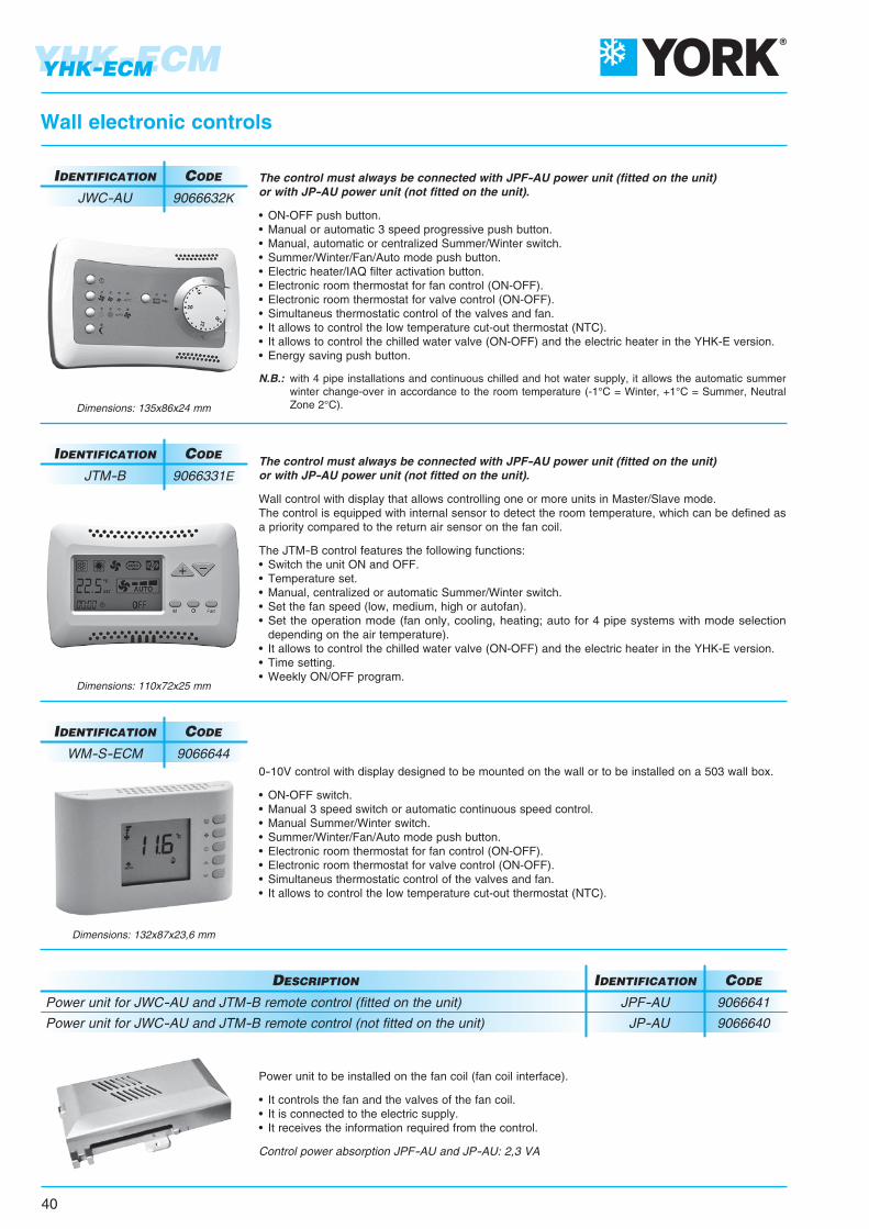
Wall electronic controls
Dimensions: 135x86x24 mm
Dimensions: 110x72x25 mm
Dimensions: 132x87x23,6 mm
The control must always be connected with JPF-AU power unit (fitted on the unit)or with JP-AU power unit (not fitted on the unit).
Wall control with display that allows controlling one or more units in Master/Slave mode.The control is equipped with internal sensor to detect the room temperature, which can be defined asa priority compared to the return air sensor on the fan coil.
The JTM-B control features the following functions:• Switch the unit ON and OFF.• Temperature set.• Manual, centralized or automatic Summer/Winter switch.• Set the fan speed (low, medium, high or autofan).• Set the operation mode (fan only, cooling, heating; auto for 4 pipe systems with mode selection depending on the air temperature).• It allows to control the chilled water valve (ON-OFF) and the electric heater in the YHK-E version.• Time setting.• Weekly ON/OFF program.
0-10V control with display designed to be mounted on the wall or to be installed on a 503 wall box.
• ON-OFF switch.• Manual 3 speed switch or automatic continuous speed control. • Manual Summer/Winter switch.• Summer/Winter/Fan/Auto mode push button.• Electronic room thermostat for fan control (ON-OFF).• Electronic room thermostat for valve control (ON-OFF).• Simultaneus thermostatic control of the valves and fan.• It allows to control the low temperature cut-out thermostat (NTC).
IDENTIFICATION CODE
JTM-B 9066331E
IDENTIFICATION CODE
WM-S-ECM 9066644
The control must always be connected with JPF-AU power unit (fitted on the unit)or with JP-AU power unit (not fitted on the unit).
• ON-OFF push button.• Manual or automatic 3 speed progressive push button.• Manual, automatic or centralized Summer/Winter switch.• Summer/Winter/Fan/Auto mode push button.• Electric heater/IAQ filter activation button.• Electronic room thermostat for fan control (ON-OFF).• Electronic room thermostat for valve control (ON-OFF).• Simultaneus thermostatic control of the valves and fan.• It allows to control the low temperature cut-out thermostat (NTC).• It allows to control the chilled water valve (ON-OFF) and the electric heater in the YHK-E version.• Energy saving push button.
N.B.: with 4 pipe installations and continuous chilled and hot water supply, it allows the automatic summer winter change-over in accordance to the room temperature (-1°C = Winter, +1°C = Summer, Neutral Zone 2°C).
IDENTIFICATION CODE
JWC-AU 9066632K
Power unit to be installed on the fan coil (fan coil interface).
• It controls the fan and the valves of the fan coil.• It is connected to the electric supply.• It receives the information required from the control.
Control power absorption JPF-AU and JP-AU: 2,3 VA
Power unit for JWC-AU and JTM-B remote control (fitted on the unit)
Power unit for JWC-AU and JTM-B remote control (not fitted on the unit)
DESCRIPTION
JPF-AU 9066641
JP-AU 9066640
IDENTIFICATION CODE
41
YHK-ECMYHK-ECM
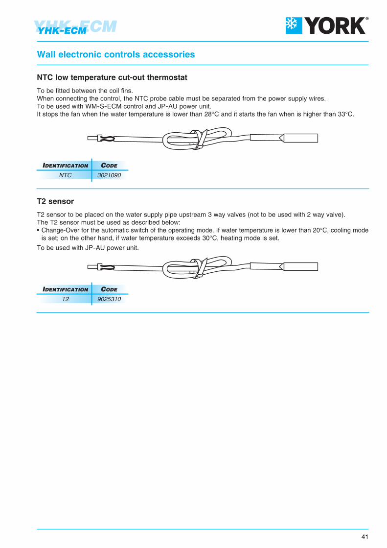
Wall electronic controls accessories
NTC low temperature cut-out thermostat
To be fitted between the coil fins.When connecting the control, the NTC probe cable must be separated from the power supply wires.To be used with WM-S-ECM control and JP-AU power unit.It stops the fan when the water temperature is lower than 28°C and it starts the fan when is higher than 33°C.
IDENTIFICATION CODE
NTC 3021090
T2 sensor
T2 sensor to be placed on the water supply pipe upstream 3 way valves (not to be used with 2 way valve).The T2 sensor must be used as described below:• Change-Over for the automatic switch of the operating mode. If water temperature is lower than 20°C, cooling mode is set; on the other hand, if water temperature exceeds 30°C, heating mode is set.
To be used with JP-AU power unit.
IDENTIFICATION CODE
T2 9025310

All the controls and their functions are described in detail from Page 44.
42
YHK-ECMYHK-ECM
All the YHKY–ECM units can be supplied in MP version. This version includesa wide range of controls, including the infra-red remote control, which allows managing one single unit
or several units by using the Modbus RTU - RS 485 communication protocol.
Units can be managed according to the Master/Slave logic (up to 20 units)or by supervisory components.
The system consists in a MP board (mounted on models YHKY–MP and YHKY–ECM–MP)and a series of controls, such as the JTM-B wall control, the RT03 infra-red remote control,
the PSM-DI multifunction control and the NET supervisory program.
Controls and units for YHKY–ECM–MP versions
RT03 infra-red remote control
PSM-DI multifunction control
JTM-B wall control
NET software
NET screenshot
PC
43
YHK-ECMYHK-ECM
0-10VdcFan Drive signal
BU
BN
PE
N
Q1
L
2
E
R3
M9
SEC1
BN
OG
WH
BK
BK
B1
Q2
1
NL3
NL2
NL1
L2
N
3EH
M12
R1
R2
L1M11
L3
L1
M10
M3
L
1
M8
M9
2
J4M5
J1
J2
J5J3 V1
V3V2
M4 V2V3
V1
M15
M7
12N
8 9 10 111213 1415
4567
High-levelALARM
ThermostatALARM
M6
L1 N
TS1
M
ECM boardpower supply
L
GNYE
P+
10VDC
P-
PE
Tp
V 3
0-10 VdcInput signal
N
A-
P15V
0A+
Tp
U
W
TS2
BN
GNYE
BN
BU
BN
BNGNYE
PE
BLAC
3
BU
Electric heater YHK-ECM-E
POWER SUPPLY230Vac 50Hz
POWER SUPPLY230Vac 50Hz
LEGEND:
M = Fan
SEC1 = Fan coil terminal board
BLAC = Inverter circuit board
B1 = Condensate level sensor
M9 = Water pump motor
E = Cold water valve
BK = Black
BN = Brown
BU = Dark Blue
OG = Orange
RD = Red
WH = White
GNYE = Yellow/Green
Inputfor electric resistance
1
Safety thermostatTS1
TS2
Thermal cut Off = 45°CAutomatic Reset
TS1
Thermal cut Off = 80°CManual Reset
TS2
Input for “E”2
Signal 0-10Vdc3
Max. ambient temperature for Cassette unit with electric coil in heating mode: 25°C
Cassette unit operating limits with electric coil
Electric diagram
ECM Model
Emission
Supply
Numberand Dia. of connecting wires
YHK 25-2-E YHK 65-2-E / 95-2-E / 110-2-E
1500 Watt
230V ~
3 x 1,5 mm2
YHK 40-2-E / 50-2-E
2500 Watt
230V ~
3 x 2,5 mm2
3000 Watt
230V ~
3 x 2,5 mm2
The Cassette 2 pipe models are available with electric resistance that is controlled in place of the heating battery valve.The electric resistance is controlled in place of the hot water valve and not as integration to it.The resistance is hermetically sealed and supplied inside the battery pipes and therefore can be only factory mounted.The electric resistances of the units are for single phase 230V supply.The Cassette includes no. 2 safety thermostats which intervene in case of internal over- heating, opening an auxiliarypower relay (included in the shunt box) which stops the power supply to the resistances.
Note: the cooling emission of the units is 95% of the emission in the tables of page 31.

The MP electronic board,mounted as per standard on the YHKY–MPand YHKY–ECM–MP versions, is set to carry outdifferent functions and adjustment modes,in order to meet the installation requirements.
These modes are selectedby setting the configuration dip switcheson the board.
• 2/4 pipe system.
• Fan ON/OFF thermostatic control.
• Valve ON/OFF thermostatic control and continuous ventilation.
• Valve and simultaneous ventilation ON/OFF thermostatic control.
• Fan operation control depending on the coil temperature (cut-out T3 probe fitted), which can be activated only in heating mode or heating and cooling mode.
• Automatic switch of the operating mode by means of T2 water probe (optional) applied on the 2 pipe system.
• Seasonal switch by means of remote contact.
• ON/OFF of the fan coil by means of the remote contact (window or clock contact).
• Electric heater control.
By activating the cut-out T3 probe function, the fan is stopped in winter when the coil temperature is lower than 32°Cand started when the temperature reaches 36°C. In summer mode, the fan stops when the temperature inside thecoil exceeds 22°C and starts when it drops below 18°C.
The following connections are located on the power board:
• Receiver for infra-red remote control.
• JTM-B wall control.
• RS 485 serial connection to manage several fan coils in Master/Slave configuration or to create a supervisory network.
44
YHK-ECMYHK / YHK-ECM
MP controls
MP electronic board

45
YHK-ECMYHK / YHK-ECM
MP controls
Wall control with display that allows controllingone or more units in Master/Slave mode.The control is equipped with internal sensor to detectthe room temperature, which can be defined as a prioritycompared to the return air sensor on the fan coil.
The JTM-B control features the following functions:
• Switch the appliance ON and OFF.
• Temperature set.
• Modify the set point (when used as a +/- 3° variation of the set point configured from NET supervisory program or PSM-DI).
• Set the fan speed (low, medium, high or autofan).
• Set the operation mode (fan only, cooling, heating; auto for 4 pipe systems with mode selection depending on the air temperature).
• Time setting.
• Weekly ON/OFF program.
• Display and change of the fan coil operation parameters.
Wall control (to be used with YHKY–MP and YHKY–ECM–MP version only)
DESCRIPTION
JTM-B 9066331E
IDENTIFICATION CODE
JTM-B wall control
Dimensions: 110x72x25 mm

46
YHK-ECMYHK / YHK-ECM
The infra-red remote control allows setting by a remote position the fan coil operation parameters.
The RT03 infra-red remote control features the following functions:
• Switch the appliance ON and OFF.
• Temperature set.
• Set the fan speed (low, medium, high or autofan).
• Set the operation mode (fan only, cooling, heating; auto for 4 pipe systems with mode selection depending on the air temperature).
• Time setting.
• 24 hours ON/OFF program.
RCS-RT03
RCS
RS
RT03
9079117
9079116
9066338
3021203
RT03 infra-red remote control with receiver supplied with separate packaging(to be used with YHKY–MP and YHKY–ECM–MP version only)
Receiver for RT03 infra-red remote control supplied with separate packaging(to be used with YHKY–MP and YHKY–ECM–MP version only)
Receiver for RT03 infra-red remote control and MD metal diffuser suppliedwith separate packaging (to be used with YHKY–MP and YHKY–ECM–MP version only)
RT03 infra-red remote control supplied with separate packaging(to be used with YHKY–MP and YHKY–ECM–MP version only)
DESCRIPTION IDENTIFICATION CODE
RT03 infra-red remote control
MP controls
IDENTIFICATION CODE
RT03 3021203
IDENTIFICATION CODE
RCS 9079116
IDENTIFICATION CODE
RCS-RT03 9079117
g
• 24 hours ON/OFF program• 24 hours ON/OFF program.
INSTALLATION EXAMPLE
WITH INFRA-RED REMOTE CONTROL

47
YHK-ECMYHK / YHK-ECM
A group of YHKY–MP can be connected via a serial link and can consequently be managed at the same time byjust one JTM-B wall control or RT03 infra-red remote control. Using the special jumper present on the MP board,one unit must be configured as the master, and all the others as slaves. It is clear that the remote control must bepointed at the receiver on the master unit. To avoid problems, it is recommended to install and connect the receiveronly on the master unit.
MP controls
The T2 sensor can be combined with MP boards to be placed on the water supply pipe upstream 3 way valves(not to be used with 2 way valve).
The T2 sensor must be used as described below:
- Change-Over for 2-pipe system for the automatic switch of the operating mode. If water temperature is lower than 20°C, cooling mode is set; on the other hand, if water temperature exceeds 30°C, heating mode is set.
IDENTIFICATION CODE
T2 9025310
T2 accessory for units with MP electronic board
With RT03 infra-red remote control
One control for each cassette One control for more cassettes (20 units max.)(MAXIMUM TOTAL LENGTH OF THE CONNECTION CABLE = 800 m)
With JTM-B wall control
One control for each cassette(MAXIMUM LENGTH OF THE CONNECTION CABLE = 20 m)
One control for more cassettes (20 units max.)(MAXIMUM TOTAL LENGTH OF THE CONNECTION CABLE = 800 m)
Belden 9841 cable
Belden 9841 cable

48
YHK-ECMYHK / YHK-ECM
Another option available for the serial communication betweenthe units is the possibility to connect up to 60 YHK units inseries and manage them with just one wall mounted PSM-DIcontroller. The wall mounted controller can be used to set theoperating mode for each individual unit connected, displaythe operating conditions of each individual unit, and set theON/OFF time sets for each day of the week (the programcan be set for all the units and for a maximum of two groupsof units).If more than 60 units need to be connected, two or morecontrollers must be used. Each unit must have a MP board.The PSM-DI control is used to manage a series of fan coils,up to a maximum of 60 units (the maximum length of the RS 485connection cable must not exceed 800 m), from one single controlpoint.
The PSM-DI control communicates via a serial line with all the units connected, with the possibility of controllingthem all together or individually. In fact, the unique address of each individual fan coil means that all the units canbe called at the same time, or the individual unit called, to perform the following functions:
- display the current operating mode, the fan speed, the set point;
- display the room temperature measured on the individual unit;
- turn all the units ON and OFF at the same time or alternatively each unit individually;
- change the operating mode (fan only, heating, cooling, automatic changeover);
- change the set point;
- modify the values and operation parameters of the fan speed.
Each function can then be sent to all the units connected, or alternatively to each individual unit.
Different set points or operating modes can be set for each individual unit.
The PSM-DI panel can also be used for the time management of the units over the week. Four ON times and fourOFF times can be set on the units for each day of the week. A different Temperature set that will be considered asOperation set for all connected appliances, can be set for each event. If the Temperature set is not entered for theindividual event, it must be set during programming for each individual unit or for the entire network.
Units without receiver or with receiver can be connected within the network: the former can receive instructions onlyfrom the PSM-DI wall mounted panel; while the latter can receive information from both the wall mounted panel(PSM-DI) and infra-red remote control. Use the infra-red remote control to force ON mode of the individual unit,if ON/OFF daily time programming has been set. The unit will regain the settings from the PSM-DI panel duringexecution of successive start-up program.
The PSM-DI panel cannot be usedtogether with the NET management program (see next page).
Note: set the configuration Dip Switches of each fan coil as illustrated in the remote control use manual, based on the required solutions.
Note: the RS 485 network’s overall length must not exceed 700/800 metres.
5
Multifunction control (to be used with YHKY–MP and YHKY–ECM–MP version only)
DESCRIPTION
PSM-DI 3021293
IDENTIFICATION CODE
PSM-DI multifunction control panel
MP controls

49
YHK-ECMYHK / YHK-ECM
Management system for a network of fan coils
Hardware/software supervisory system(to be used with YHKY–MP and YHKY–ECM–MP version only)
DESCRIPTION
NET 9079118
IDENTIFICATION CODE
NET program for managing a network of YORK MP fan coils
NET is a centralised control systemfor networks of YORK MP fan coils, based on softwarethat runs on LINUX™ operating system(the program is provided pre-installed on a PC).The NET software offersa practical and economical solution for managing the units,with the simple click of the mouse.
The main characteristics include:
- simplicity of use;
- an extremely complete and functional weekly program;
- possibility to access the historical operating data for each individual unit connected.
The program exploits all the potential of our unitswith remote controls, representing an addition to the latter.
The NET program is a control toolthat can be used as a replacement for the remote control, or in parallel,however the settings made using NET can have priorityover those made using the remote control.
The program can be used to:
- Create uniform groups (groups of units on individual floors, in offices or rooms).
- Save weekly programs configured for different types of operation (summer, winter, mid seasons, closing periods etc.); these can then be recalled and activated with a simple click of the mouse. Weekly on/off cycles can be set for individual units or groups of units.
- Set the operating conditions for each individual unit or groups of units (operating mode, fan speed, temperature setting).
- Set the set point limits for each individual unit or groups of units.
- Switch each individual unit or groups of units ON or OFF.

50
YHK-ECMYHK / YHK-ECM
Management system for a network of fan coils
The main program screen can display and interact with the entire network of units. An individual unit, a group ofunits or the entire network can be called so as to make modifications to the operating mode and the set point. Theuser can then check the operating status of each individual unit, read the room temperature, the coil temperatureand the operating status of the condensate drain pump or any alarms.
“MO
NIT
OR
ING
” S
CR
EE
N
The “MONITORING” SCREEN
shows the units thatare connected to the networkand scanned by the program.
Displaying a unit
The icon of the terminal unitprovides the following information:
- Unit name ( 00.01.01)
- Set temperature ( SETP )
- Room temperature ( AT )
- Unit status: ON (Green) or OFF (Red)
- Mode: • Summer • Auto
• Winter • Fan only
- Fan speed: • Low • High
• Medium • AutoFan

USB-RS 485
Outputsfor system
Powerinput
CONVERTER
RS 485
Outputsfor system
Powerinput
Outputsfor system
Powerinput
MC2 Jumperto be closed.
End of network.
Cassetteunit
Cassetteunit
Cassetteunit
60 units max. (*)
NET
51
YHK-ECMYHK / YHK-ECM
Management system for a network of fan coils
“EV
EN
T M
AN
AG
EM
EN
T”
SC
RE
EN
RS 485 serial connection cable
Shielded cable to be used:Belden 9841, RS-485, 1x2x24 AWG SFTP, 120 Ohm
Time bands are available for each day of the week. The time and the type of operation to be performed by the unitcan be set for each band. The time and the operating parameters can then be displayed before being sent to theunit and implemented.
The “Weekly Program” can be used to set the unit operating parameters for each day of the week. Up to 20 differentweekly programs can be set.
PC NET Software
Connectionof a CassetteYORK YHKY–MP orYHKY–ECM–MP network
(*) In the event of more than 60 units, add one or more Router-S (see next page).

52
YHK-ECMYHK / YHK-ECM
PSM-DI and NET accessories
SIOS is a board equipped with 8 relayswith potential free contact to control the activationor deactivation of remote electric utilities.Moreover, the board has 8 digital inlets to displaythe actuators or external consents, such as motor or other.
The SIOS boards can be connected:
- inside a network managed by NET;
- to a PSM-DI panel (one SIOS for each PSM-DI panel).
The Router-S is an electronic board that:
- allows creating networks with more than 60 units (minimum 2 Router-S are required) or to divide the network (per floor, building, etc.);
- it allows creating a Master/Slave sub-network to be controlled as an indipendent group.
The Router-S can be used only inside a network managed by NET.
The number of Router-S to be used is: - up to 60 units: no Router-S - from 61 to 120 units: 2 Router-S - every 60 subsequent units: 1 additional Router-S
IDENTIFICATION CODE
SIOS 3021292
IDENTIFICATION CODE
Router-S 3021290

Introduction
The OCA version has been designed for all environments where false ceilings are not featuredor cannot be constructed.The cover cabinet fits perfectly to the air intake and outlet diffuser, maintaining the appealingdesign that defines the YHK series. The water fittings can be turned to point upwards.
The OCA series includes 7 models, with an installation height of up to 5 m, thanks to the highlyflexible adjustment of the air distribution louvers.
All the technical specifications described on the previous pages remain the same, while keepingin mind that:- the OCA series features one coil only (two pipe systems)- there is no possibility of fresh air intake- there is no possibility of additional electric resistance
The OCA version features a special casing delivered in separate packaging; this must only befitted after having installed the YHK unit and completed the water and electrical connections.
53
YHK Cassette OCAYHK Cassette OCA

YHK Cassette OCA
Dimensions and Weights
YHK 20-2-OCA / YHK 25-2-OCA / YHK 40-2-OCA / YHK 50-2-OCA
Casing code: 9079240
Casing weight: 5 kg (7,5 kg with the packaging)
YHK 65-2-OCA / YHK 95-2-OCA / YHK 110-2-OCA
Casing code: 9079250
Casing weight: 10,5 kg (13,5 kg with the packaging)
Warning: the electrical and water connections must enter the unit from above and must not interfere with the casing.
54
YHK Cassette OCA
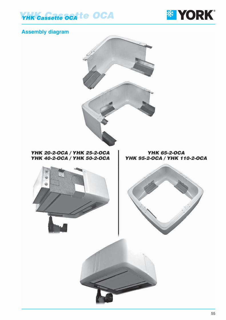
55
YHK Cassette OCAYHK Cassette OCA
Assembly diagram

YHK Cassette OCA
56
YHK Cassette OCA
Components of the casing:
Valve kit
The casing includes:
A – 4 corner covers
B – 4 bottom brackets
C – 4 top brackets
D – Condensate collection tray
E – Hardware (45 3.9x9.5mm TCX screws)
F – Instruction sheet
The valve fittings allow the water pipes to be connected from above.
For the specifications of the valves, see page 15.
YHK 20-2-OCA / YHK 25-2-OCAYHK 40-2-OCA / YHK 50-2-OCA
Code 9079155
YHK 65-2-OCAYHK 95-2-OCA / YHK 110-2-OCA
Code 9079156

The descriptions and illustrations provided in this publication are not binding:Johnson Controls reserve the right, whilst maintaining the essential characteristics
of the types described and illustrated, to make, at any time,without the requirement to promptly update this piece of literature,
any changes that it considers useful for the purposeof improvement or for any other manufacturing or commercial requirements.

YHK
- 0
/16
Cod
. 99A
4790
142
F/0
/16