yoshiaki kuwata, gaston a. fiore, justin teo, emilio ...acl.mit.edu/papers/kuwatairos08.pdf ·...
TRANSCRIPT

Motion Planning for Urban Driving using RRT
Yoshiaki Kuwata, Gaston A. Fiore, Justin Teo, Emilio Frazzoli, and Jonathan P. How
Abstract— This paper provides a detailed analysis of themotion planning subsystem for the MIT DARPA Urban Chal-lenge vehicle. The approach is based on the Rapidly-exploringRandom Trees (RRT) algorithm. The purpose of this paper isto present the numerous extensions made to the standard RRTalgorithm that enable the on-line use of RRT on robotic vehicleswith complex, unstable dynamics and significant drift, whilepreserving safety in the face of uncertainty and limited sensing.The paper includes numerous simulation and race results thatclearly demonstrate the effectiveness of the planning system.
I. INTRODUCTION
The DARPA Urban Challenge (DUC) was the third install-ment of a series of ground-breaking races for autonomousground robots. The major new feature of the DUC comparedto previous races was the introduction of traffic, with upto 70 robotic and human-driven vehicles on the course,resulting in hundreds of unscripted robot-on-robot (and roboton human driven vehicle) interactions. In order to ensuresafe operations, all vehicles were required to abide by thetraffic laws and rules of the road. For example, vehicles wereexpected to stay in the correct lane, maintain a safe speed,yield to other vehicles at intersections, pass other vehicleswhen safe to do so, recognize blockages and execute U-turnswhen needed, and park in an assigned space.
Developing a robotic vehicle that could complete theDUC was a major systems engineering effort, requiring thedevelopment and integration of state-of-the-art technologiesin planning, control, and sensing [1], [2]. This paper providesadditional details on the motion planning subsystem of MIT’svehicle, called Talos. This subsystem computes a path toreach a goal point specified by a higher-level subsystem (theNavigator), while avoiding collisions with other vehicles,static obstacles, and abiding by the rules of the road. Theoutput of the motion planning subsystem is in turn fed toa lower-level system (the Controller), interfacing directly tothe vehicle, and responsible for the execution of the motionplan.
There are many approaches to the motion planning prob-lem available in the literature; and we will not discusstheir relative merits but refer the reader to [3]–[7]. Theprimary challenges in designing the motion planning sub-system for DUC resulted from: (i) complex and unstablevehicle dynamics, with substantial drift, (ii) limited sensing
Y. Kuwata was a Postdoctoral Associate in the Dept. of Aeronautics andAstronautics, Massachusetts Institute of Technology (MIT), Cambridge, MA02139, USA [email protected]
G. Fiore and J. Teo are with the Dept. of Aeronautics and Astronautics,MIT, [email protected], [email protected]
E. Frazzoli and J. How are with the Faculty of the Dept. of Aeronauticsand Astronautics, MIT, [email protected], [email protected]
capabilities in an uncertain, time-varying environment, (iii)temporal and logical constraints, arising from the rules ofthe road. Our planning system is based on the Rapidly-exploring Random Trees (RRT) algorithm [8], an incrementalsampling-based method [6, Section 14.4]. The main reasonsfor this choice were: (i) Sampling-based algorithms are appli-cable to very general dynamical models; (ii) The incrementalnature of the algorithms lends itself easily to real-time, on-line implementation, while retaining certain completenessguarantees; (iii) Sampling-based methods do not require theexplicit enumeration of constraints, but allow trajectory-wisechecking of possibly very complex constraints.
However, the application of incremental sampling-basedmotion planning methods to robotic vehicles with complexand unstable dynamics, such as the Landrover LR3 used forthe race, is far from straightforward. For example, the unsta-ble nature of the vehicle dynamics requires the addition ofa path-tracking control loop whose performance is generallyhard to characterize. Moreover, the momentum of the vehicleat speed must be taken into account, making it impossible toensure collision avoidance by point-wise constraint checks.In fact, to the best of our knowledge, RRTs have never beenused in on-line planning systems for robotic vehicles withthe above characteristics, but have been restricted either tosimulation, or to kinematic, essentially driftless, robots (i.e.,can stop instantaneously by setting the control input to zero).
The rest of the paper is organized as follows. Following theoverview of the algorithm in Section II, Section III presentsseveral extensions made to RRT. Section IV discusses theeffectiveness of our motion planning system, based on theanalysis of actual data collected during the DUC race.
II. OVERVIEW OF THE APPROACH
A. Problem Statement
Given a near-term target, and a low-level controller thatcan track a path and a speed command, the problem state-ment for the motion planner is to provide a path and a speedcommand to the controller, such that the vehicle avoid obsta-cles and stay in lane boundaries. In order to account for thedynamic nature of the urban driving, the planner must be ableto quickly react to the change in the perceived environment.Furthermore, the perceived information has inherent noise,and the RRT must be robust to the uncertainties.
B. Rapidly-exploring Random Tree (RRT)
RRT algorithms grow a tree of dynamically feasible tra-jectories by sampling numerous points randomly. In contrastto the standard RRT, which samples the input to the vehicle,our RRT algorithm samples the input to the controller [9].

Road departure => Infeasible path
Car
Obstacle collision=>Infeasible pathFeasible paths
Divider crossing => Infeasible path
Fig. 1. Motion plans are propagated using the vehicle’s dynamical model.Propagated paths are then evaluated for feasibility.
The dynamically feasible trajectory is obtained by runningforward a simulation of the closed-loop system, consistingof the vehicle model and the controller. By using a stableclosed-loop system, this approach has the advantage ofenabling the efficient use of RRT algorithms on vehicleswith unstable open-loop dynamics. For example, since thecontroller generates high-rate commands that stabilize andguide the vehicle along a given path, the motion planneroutput does not need to be very dense in time. As shownin Figure 1, the tree consists of the input to the controller(shown in blue) and the predicted trajectory (shown in greenand red).
Algorithm 1 shows the overall flow. Similar to the stan-dard RRT, the algorithm performs sampling (line 5), nodeselection (6), expansion (7), and constraint check (9), in thisorder. The planner provides the command to the controller ata fixed rate, and the tree expansion continues until this timelimit is reached (23). The best trajectory is selected and thensent to the controller (28), and the tree expansion is resumedafter updating the vehicle states and the situational awareness(2). The major extensions to RRT are presented in Section III.
The plan being executed is continuously monitored forcollisions; should it become infeasible, and no other feasibletrajectory is found while the car is moving, the plannercommands an emergency braking maneuver. Such emergencyconditions may arise only as a consequence of mismatchesbetween the physical world and its representation used inthe previous planning cycles (e.g., sudden appearance of anundetected obstacle in front of the vehicle).
For the selection of the best node sequence on line 28, eachnode stores two estimates of the cost-to-go: a lower boundand an upper bound. The Euclidean distance between thethe node location and the target location is set as the lowerbound. The upper bound is ∞ when no feasible trajectoryto the target is found. Otherwise, the summation of the edgecosts from the node to the target along the best node sequence
Algorithm 1 RRT-based planning algorithm1: repeat2: Receive current vehicle states and environment3: Propagate states by computation time limit4: repeat5: Take a sample for input to controller6: Select a node in tree using heuristics7: Propagate from selected node to the sample until
the vehicle stop8: Add branch nodes on the path9: if propagated path is feasible with the drivability
map then10: Add sample and branch nodes to tree11: else12: if all the branch nodes are feasible then13: Add branch nodes to the tree and mark them
as unsafe14: end if15: end if16: for each newly added node v do17: Propagate to the target18: if propagated path is feasible with drivability map
then19: Add path to tree20: Set cost of propagated path as upper bound of
cost-to-go at v21: end if22: end for23: until the time limit is reached24: Choose best safe trajectory in tree, and check feasi-
bility with latest drivability map25: if best trajectory is infeasible then26: Remove infeasible portion from tree, goto line 2427: end if28: Send the best trajectory to controller29: until Vehicle reaches the target
gives an upper bound. Details on the edge cost are given inSubsection III-D.
III. RRT EXTENSIONS
In order to efficiently generate the path in a dynamic anduncertain environment, several extensions have been made tothe existing RRT approach [10]. The following subsectionsprovide more details on the design choices embedded in theRRT algorithm. The line number in the subsection headingcorresponds to that of Algorithm 1.
A. Biased sampling: line 5
The first extension to the RRT algorithm in [10] is that ituses the physical and logical structure of the environment tobias the sampling [11]. This biasing significantly increasesthe probability of generating feasible trajectories, enablingthe online use of RRT. The samples are taken in 2D, andthey are used to form the input to the steering controller.
The sample (xsample,ysample) is taken randomly but has someparameters to bias its location/shape, i.e.,[
xsampleysample
]=[
x0y0
]+ r[
cosθ
sinθ
]with
{r = σr|nr|+ r0θ = σθ nθ +θ0
where nr and nθ are random variables that have Gaussiandistributions, σr and σθ give the 1-σ values of the radialand circumferential direction, r0 and θ0 are the offsets, and(x0, y0) is the center of the Gaussian cloud.
The uniqueness of this approach is that by varying thebias values based on the situational information, the plannercan generate various maneuvers including lane following,passing, U-turn, and parking. Team MIT used a singleplanner for the entire race, which shows the flexibility andthe extensibility of this planning algorithm.
B. Tree Expansion Heuristics: line 6
The algorithm has two connection heuristics, as introducedin [10]. Before a feasible trajectory to the target is found, thetree is grown mainly according to an exploration heuristicthat attempts to connect the sample to the nearest node inthe tree. The trajectory from the node to the sample tendsto be short, and therefore is likely to be collision free.Then, most samples are added to the tree, resulting in rapidexploration of the environment with a smaller number ofcollision checks. This heuristic is widely used in the standardRRT, but when the vehicle has a minimum turn radius ρ , asin the car, the Euclidean distance between two points can bea poor estimate of the achievable path length.
A key difference between our approach and the previouswork is the selection criteria of the nearest node, which usesthe Dubins path length from the node to the sample. The nodein the tree has a 2D position and a heading, and withoutloss of generality, it is assumed to be at the origin p0 =(0, 0, 0) ∈ SE(2). The sample is a 2D point represented byq = (x, y) ∈ R2. Since for the choice of p0, the Dubins pathlengths from p0 to the points (x, y) and (x,−y) are equal,it suffices to consider the case q = (x, |y|) ∈ R×R+. Theminimum length Lρ(q) of a Dubins path from p0 to q canbe obtained analytically [12]. Let ρ denote the minimumturning radius of the vehicle. By defining D+
ρ = {z ∈ R2 :‖z− (0, ρ)‖< ρ}, the minimum length is given by
Lρ(q) = Lρ(q) =
{f (q) for q /∈D+
ρ ;g(q) otherwise,
where
f (q) =√
d2c (q)−ρ2 +ρ
(θc(q)− cos−1 ρ
dc(q)
)g(q) = ρ
(2π−α(q)+ sin−1 x
df(q)+ sin−1 ρ sin(α(q))
df(q)
).
Here, dc(q) =√
x2 +(|y|−ρ)2 is the distance of q fromthe point (0, ρ), θc(q) = atan2(x,ρ − |y|) is the angle ofq from the point (0, ρ), measured counter-clockwise fromthe negative y-axis, df(q) =
√x2 +(|y|+ρ)2 is the distance
of q from the point (0,−ρ), and α(q) = cos−1(
5ρ2−df(q)2
4ρ2
).
Note that the atan2 function is the 4 quadrant inverse tangent
function with atan2(a,b) = tan−1( a
b
), and its range must be
set to be [0,2π) to give a valid distance. This analyticalcalculation allows us to quickly evaluate all the nodes in thetree for a promising connection point.
Once a feasible trajectory to the target is found, the tree isgrown primarily using an optimization heuristic that attemptsto smooth out the trajectories. The nodes are now sorted byh(v)+ Lρ(q), where h(v) represents the cost from the rootto the node v. This attempts to minimize the path cost fromthe root to the sample, resulting in a tree of trajectories thatare close to optimal.
The implemented algorithm actually used both expansionmodes at the same time but tended to place more emphasison one or the other. The reason being that, even beforehaving a trajectory that reaches the goal, there are benefits inperforming some path optimization to reduce the wavinessin the paths. Similarly, once a feasible trajectory to thegoal has been found, there are still benefits in exploringthe environment in case there is a better route, or anotherobstacle appears. In our implementation, the ratio of explo-ration vs. optimization heuristics was 70% vs. 30% before atrajectory to the target is found, and 30% vs. 70% once it isfound.
C. Safety as an Invariant Property: line 7
Ensuring the safety of the vehicle is an important feature ofany planning system, especially because the vehicle operatesin a dynamic and uncertain environment. We define a state tobe safe if the vehicle can remain in that state for an indefiniteperiod of time, without violating the rules of the road andavoiding collisions with stationary and moving obstacles –where the latter are assumed to maintain their current drivingpath. A complete stop is used as safe states in this paper.More general notions of safe states are available [10], [13].The large circles in Figure 1 show the safe stopping nodesin the tree. Each forward simulation terminates when thevehicle comes to a stop. By requiring that all leaves in thetree are safe states, this approach guarantees that there isalways a feasible way to come to a stop while the car ismoving. Unless there is a safe stopping node at the end ofthe path, the vehicle does not start executing it.
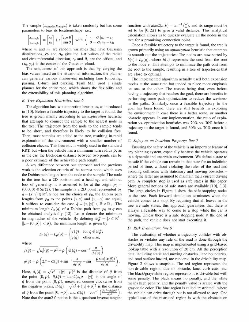
D. Risk Evaluation: line 9
The evaluation of whether a trajectory collides with ob-stacles or violates any rule of the road is done through thedrivability map. This map is implemented using a grid-basedlookup table with a resolution of 20 cm. All the perceptiondata, including static and moving obstacles, lane boundaries,and road surface hazard, are rendered in the drivability map.Figure 2 shows a snapshot. The red region represents thenon-drivable region, due to obstacle, lane, curb cuts, etc.The black/gray/white region represents it is drivable but withsome penalty. The black means no penalty, and the whitemeans high penalty, and the penalty value is scaled with thegray-scale color. The blue region is called “restricted”, wherethe vehicle can drive through but is not allowed to stop. Onetypical use of the restricted region is with the obstacle on

Fig. 2. Drivability map and its annotation.
the road. The vehicle stops with enough standoff distance tothe obstacle, as shown in Figure 2, but once the oncominglane becomes free to drive, the vehicle can go through therestricted area to pass the obstacle in the lane.
The penalty represents the risk in the environment, suchas proximity to obstacles or lane boundaries, and curb cutsthat are too faint to declare non-drivable. When evaluatingthe feasibility of the trajectory using the lookup table, thepenalty stored in the drivability map is also obtained. Thecost of the edge is then defined as the sum of travel time andthe path integral of the penalty. Using this combined metric,the best trajectories tend to stay away from obstacles andlane boundaries, while allowing the vehicle to come close toconstraints on a narrow road.
E. Unsafe Node: line 13
Another critical difference from the previous work [10]is the notion of “unsafe” node. In [10], when the propa-gated trajectory is not collision-free, the entire trajectory isdiscarded. In our approach, when only the final portion ofthe propagated trajectory is infeasible, the feasible portionof the trajectory is added to the tree. This avoids wastingthe computational effort to find a good sample, propagate,and check for collision, while retaining the possibility toexecute the portion that is found to be feasible. Because thistrajectory does not end in a stopped state, the newly addednodes are marked as “unsafe”. Then, if a safe trajectory,which ends in a stopped state, is added to the unsafe node,the node is marked as safe. When selecting the best trajectory(line 24) to send to the controller, the unsafe nodes are notconsidered. This approach uses unsafe nodes as potentialconnection points for samples, increasing the density of thetree, while ensuring the safety of the vehicle.
F. Lazy Check: line 24
In contrast to most motion planning algorithms, our RRTalgorithm keeps growing the tree while the vehicle executeits portion. When the perceived environment is updated, thefeasibility of each edge in the tree should be checked withthe latest situational awareness. However, in the dynamicallychanging environment, a large tree would require constantfeasibility re-checking for its thousands of edges, which
Fig. 3. Planning around obstacles. The vehicle started in the bottom, andthe goal is in the upper left corner.
reduces the time the algorithm can spend on growing thetree.
The approach taken to overcome this issue was to re-evaluate the edge feasibility only when the edge is selectedas the best trajectory sequence and is being sent to the con-troller. When the best trajectory is infeasible, the infeasibleportion of the tree is deleted and the next best sequenceis selected for re-evaluation. This so-called “lazy check”enables the algorithm to focus mainly on growing the tree,while ensuring that the executed trajectory is feasible inthe latest drivability map. The difference from the previouswork [14], [15] is that the lazy check in this paper isabout re-checking of the constraints for previously feasibleedges, whereas the previous work is about delaying the firstcollision detection in the static environment.
One limitation with the lazy check is that the penaltystored in the tree could be based on the obsolete situationalawareness. Then, the best selected trajectory could be veryclose to the constraints. As long as it is feasible with the latestmap, the planner sends it to the controller. In the constantly-changing dynamic environment, however, the computationalefficiency obtained by the lazy check typically outweighs thepotential risk to come close to the constraints.
IV. APPLICATION RESULTS
This section presents four examples from simulation anddata logged during the DUC. The planner runs at ∼10 Hz,and the average number of samples generated was about700 samples per second on a dual-core 2.33 GHz Intel Xeonprocessor. Note that because we sample the controller input,a single sample could create a trajectory as long as a fewseconds. The tree had about 1200 nodes on average.
Figure 3 shows navigation in the obstacle field. The orangeline segments represents the input to the controller, generatedby the sampling, and the green line shows the correspondingpredicted trajectory. The following colors were used to

Fig. 4. Planning of a parking maneuver. Talos enters the zone from theleft (top figure) aiming for a given parking point. Talos navigates aroundthe central obstacle and perceives the parked cars around the target, whilecontinuously planning a feasible path to the parking spot (bottom figure).
indicate different types of trajectories in the tree: purple(reaching the target), light brown (safe but not reachingthe target), red (unsafe), and cyan (reverse). Several pathssuccessfully reach the goal, and other paths explore the spacearound and between obstacles. For example, the tree containspaths, that reach the target by going to the right of obstacles;however, these paths are not selected because they are not ofminimal cost. Note that unlike many implementations of theRRT, the generated paths are smooth. This behavior resultsfrom the propagation over the closed-loop system, and theoptimization heuristics used when connecting samples to thetree.
Figure 4 shows the tree during the parking exercise in arun at the National Qualifying Event (NQE). Talos found atrajectory to the parking spot immediately after entering theparking zone, and the top figure demonstrates the explorationcapabilities of the algorithm. In addition to the several pathsthat reach the parking spot, some paths reach the parkingspot with different headings, and some others go around thepartially detected large obstacle in the middle. As the vehicleproceeds, several obstacles were detected around the parkingspot, as shown in the bottom figure. The tree contains various
forward and reverse trajectories to complete the tight parkingmaneuver.
The third result is the U-turn, one of the more elaboratemaneuvers required for the DUC, as shown in Figure 5.Biased sampling consisting of three Gaussian clouds withdifferent traveling directions efficiently constructed a U-turn maneuver. The first cloud contains forward samples,generated to the left-front of the vehicle to initiate the turn.The second set consists of reverse samples, generated tothe right-forward of the vehicle, which will be used duringthe reverse maneuver after executing the first forward legof the turn. The third set is forward samples, generated tothe left-rear of the current vehicle location for use whencompleting the turn. The parameter values used for each ofthe three sets are: σr = 8, σθ = π/10, r0 = 3, θ0 = 4π/9(first cloud); σr = 10, σθ = π/10, r0 = 5, θ0 =−π/4 (secondcloud); and σr = 12, σθ = π/10, r0 = 7, θ0 = π (third cloud).The first Gaussian cloud is centered on the location of thevehicle before initiating the U-turn maneuver, whereas theother two clouds are centered on the location of the selectedsample from the preceding cloud. Figure 5a is a snapshotof sample points generated in 0.1 second. A small cloud ofreverse samples is also generated behind the vehicle in caseit stopped very close to the road blockage, requiring a reversemaneuver to start the U-turn.
The last result in Figure 6 shows lane following along acurvy section of a road during the Urban Challenge Event(UCE). Talos is in the left of the figure heading towards theright. Note that a curb, shown by a red line near the bottomof the lane, projects into the offline estimate of the laneboundaries. This narrows the part of road that is passable,a challenging situation for the motion planner. In normaldriving conditions, the sampling was biased along the lane,and the RRT successfully finds smooth trajectories along thenarrow curvy lane.
V. CONCLUSION
This paper presented the design and implementation ofan efficient and reliable motion planning system, based onRRTs, for Team MIT’s entry to the DUC. The standardRRT is extended in several ways to be used for a largerobotic vehicle driving in the dynamic and uncertain urbanenvironment. To improve the computational efficiency, theinput to the closed-loop system is sampled, which alsoenables RRT to handle complex/unstable dynamics of thevehicle. The lazy check enables RRT to focus on the treeexpansion even with the constantly changing situationalawareness. The uncertainty in the environment is captured inthe form of a risk penalty in the tree. The sampling using theenvironmental structure also significantly reduced the timeto find trajectories for various maneuvers. The safety of thevehicle is guaranteed by requiring that the trajectory sentto the controller end in a stopping state. The advantages ofthese features are demonstrated through several simulationand race results.
The algorithm was not tuned to any specific test casesposed by DARPA during the NQE or UCE. Furthermore,

(a) (b) (c) (d)
Fig. 5. Planning of a U-turn maneuver. Figures 5b, 5c, and 5d show different evolutions of the tree as the vehicle executes a U-turn. Notice in Figure5d the trace of the path followed by the vehicle (shown in yellow).
Fig. 6. Planning along a lane that becomes increasingly narrow due todetected curbs (red line emerging into the lane on the bottom). The motionplanner is still able to find feasible trajectories that follow the road curvature.
there were numerous traffic and intersection scenarios thathad never been tested before, and yet the motion plannerdemonstrated that it was capable of handling these situationssuccessfully. The completion of the UCE using a singleplanner clearly demonstrated that this is a general-purposemotion planner capable of handling uncertain and verydynamic driving scenarios.
ACKNOWLEDGMENT
Research sponsored by DARPA, Program: Urban Challenge,DARPA Order No. W369/00, Program Code: DIRO. Issuedby DARPA/CMO under Contract No. HR0011-06-C-0149,with J. Leonard, S. Teller, J. How at MIT and D. Barrett atOlin College as the PI’s. The authors gratefully acknowledgethe support of the MIT Urban Challenge Team, particularlyDr. Luke Fletcher and Edwin Olson for developing thedrivability map, David Moore for the Navigator, and SertacKaraman for his contributions to the low-level controller.
REFERENCES
[1] K. Iagnemma and M. Buehler, eds., “Special issue on the 2007 DARPAUrban Challenge,” Journal of Field Robotics, 2008, to appear.
[2] J. Leonard, J. How, S. Teller, M. Berger, S. Campbell, G. Fiore,L. Fletcher, E. Frazzoli, A. Huang, S. Karaman, O. Koch, Y. Kuwata,D. Moore, E. Olson, S. Peters, J. Teo, R. Truax, M. Walter, D. Barrett,A. Epstein, K. Mahelona, K. Moyer, T. Jones, R. Buckley, M. Attone,R. Galejs, S. Krishnamurthy, and J. Williams, “A perception drivenautonomous urban robot,” submitted to International Journal of FieldRobotics, 2008.
[3] J.-C. Latombe, Robot Motion Planning. Boston, MA: Kluwer, 1991.[4] J.-P. Laumond, Ed., Robot Motion Planning and Control, ser. Lectures
Notes in Control and Information Sciences. Springer Verlag, 1998,vol. 229.
[5] H. Choset, K. Lynch, S. Hutchinson, G. kantor, W. Burgard,L. Kavraki, and S. Thrun, Principles of Robot Motion: Theory,Algorithms, and Implementations. Boston, MA: MIT Press, 2005.
[6] S. M. LaValle, Planning Algorithms. Cambridge, U.K.: CambridgeUniversity Press, 2006, available at http://planning.cs.uiuc.edu/.
[7] K. Iagnemma and M. Buehler, “Special issue on the DARPA GrandChallenge: Editorial,” Journal of Field Robotics, vol. 23, no. 9, pp.655–656, 2006.
[8] S. M. LaValle and J. J. Kuffner, “Randomized kinodynamic planning,”International Journal of Robotics Research, vol. 20, no. 5, pp. 378–400, May 2001.
[9] Y. Kuwata, J. Teo, S. Karaman, G. Fiore, E. Frazzoli, and J. How,“Motion Planning in Complex Environments using Closed-loop Pre-diction,” submitted to AIAA Conference on Guidance, Navigation, andControl.
[10] E. Frazzoli, M. A. Dahleh, and E. Feron, “Real-time motion planningfor agile autonomous vehicles,” AIAA Journal of Guidance andControl, vol. 25, no. 1, pp. 116–129, 2002.
[11] D. Hsu, T. Jiang, J. Reif, and Z. Sun, “The bridge test for samplingnarrow passages with probabilistic roadmap planners,” in ProceedingsIEEE International Conference on Robotics & Automation, 2003.
[12] J. J. Enright, E. Frazzoli, K. Savla, and F. Bullo, “On multiple uavrouting with stochastic targets: Performance bounds and algorithms,”in Proceedings AIAA Guidance, Navigation, and Control Conferenceand Exhibit, Aug. 2005.
[13] T. Schouwenaars, J. How, and E. Feron, “Receding horizon pathplanning with implicit safety guarantees,” in Proceedings AmericanControl Conference, vol. 6, Jun. 2004.
[14] R. Bohlin and L. Kavraki, “Path planning using Lazy PRM,” in Pro-ceedings IEEE International Conference on Robotics & Automation,2000.
[15] G. Sanchez and J.-C. Latombe, “A single-query bi-directional proba-bilistic roadmap planner with lazy collision checking,” in ProceedingsInternational Symposium on Robotics Research, 2001.