yz model a magnetic bearing centrifugal chiller with
TRANSCRIPT
YZ MODEL A MAGNETIC BEARING CENTRIFUGAL CHILLER
WITH OPTIVIEW™ CONTROL CENTER
CENTRIFUGAL LIQUID CHILLERSWITH R-1233zd REFRIGERANT
OPERATIONS AND MAINTENANCE NEW RELEASE Form 161.01-OM1 (618)
Issue Date: June 8, 2018
035-27132-100
JOHNSON CONTROLS2
FORM 161.01-OM1 ISSUE DATE: 6/8/2018
This equipment is a relatively complicated apparatus. During rigging, installation, operation, maintenance, or service, individuals may be exposed to certain com-ponents or conditions including, but not limited to: heavy objects, refrigerants, materials under pressure, rotating components, and both high and low voltage. Each of these items has the potential, if misused or handled improperly, to cause bodily injury or death. It is the obligation and responsibility of rigging, instal-lation, and operating/service personnel to identify and recognize these inherent hazards, protect themselves, and proceed safely in completing their tasks. Failure to comply with any of these requirements could result in serious damage to the equipment and the property in
IMPORTANT!READ BEFORE PROCEEDING!
GENERAL SAFETY GUIDELINES
which it is situated, as well as severe personal injury or death to themselves and people at the site.
This document is intended for use by owner-authorized rigging, installation, and operating/service personnel. It is expected that these individuals possess independent training that will enable them to perform their assigned tasks properly and safely. It is essential that, prior to performing any task on this equipment, this individual shall have read and understood the on-product labels, this document and any referenced materials. This in-dividual shall also be familiar with and comply with all applicable industry and governmental standards and regulations pertaining to the task in question.
SAFETY SYMBOLS
The following symbols are used in this document to alert the reader to specific situations:
Indicates a possible hazardous situation which will result in death or serious injury if proper care is not taken.
Indicates a potentially hazardous situa-tion which will result in possible injuries or damage to equipment if proper care is not taken.
Identifies a hazard which could lead to damage to the machine, damage to other equipment and/or environmental pollu-tion if proper care is not taken or instruc-tions and are not followed.
Highlights additional information useful to the technician in completing the work being performed properly.
External wiring, unless specified as an optional connection in the manufacturer’s product line, is not to be connected inside the control cabinet. Devices such as relays, switches, transducers and controls and any external wiring must not be installed inside the micro panel. All wiring must be in accor-dance with Johnson Controls’ published specifications and must be performed only by a qualified electrician. Johnson Controls will NOT be responsible for damage/problems resulting from improper connections to the controls or application of improper control signals. Failure to follow this warn-ing will void the manufacturer’s warranty and cause serious damage to property or personal injury.
JOHNSON CONTROLS 3
FORM 161.01-OM1 ISSUE DATE: 6/8/2018
CHANGEABILITY OF THIS DOCUMENT
In complying with Johnson Controls’ policy for contin-uous product improvement, the information contained in this document is subject to change without notice. Johnson Controls makes no commitment to update or provide current information automatically to the man-ual owner. Updated manuals, if applicable, can be ob-tained by contacting the nearest Johnson Controls Ser-vice office or accessing the Johnson Controls QuickLIT website at http://cgproducts.johnsoncontrols.com.
Operating/service personnel maintain responsibility for the applicability of these documents to the equipment. If there is any question regarding the applicability of
these documents, the technician should verify whether the equipment has been modified and if current litera-ture is available from the owner of the equipment prior to performing any work on the chiller.
CHANGE BARSRevisions made to this document are indicated with a line along the left or right hand column in the area the revision was made. These revisions are to technical in-formation and any other changes in spelling, grammar or formatting are not included.
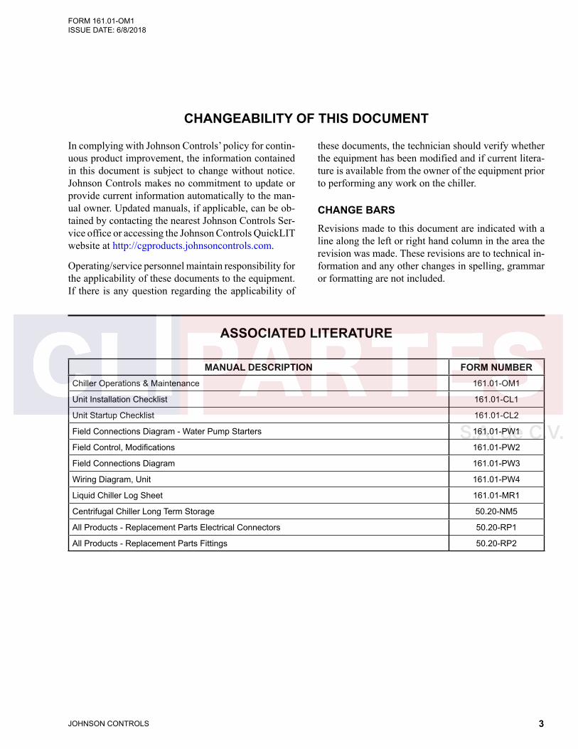
ASSOCIATED LITERATURE
MANUAL DESCRIPTION FORM NUMBERChiller Operations & Maintenance 161.01-OM1
Unit Installation Checklist 161.01-CL1
Unit Startup Checklist 161.01-CL2
Field Connections Diagram - Water Pump Starters 161.01-PW1
Field Control, Modifications 161.01-PW2
Field Connections Diagram 161.01-PW3
Wiring Diagram, Unit 161.01-PW4
Liquid Chiller Log Sheet 161.01-MR1
Centrifugal Chiller Long Term Storage 50.20-NM5
All Products - Replacement Parts Electrical Connectors 50.20-RP1
All Products - Replacement Parts Fittings 50.20-RP2
JOHNSON CONTROLS4
FORM 161.01-OM1 ISSUE DATE: 6/8/2018
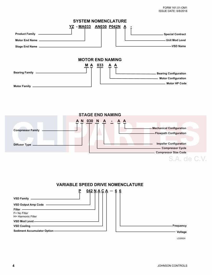
Compressor Family
Diffuser Type
Compressor Size CodeCompressor Cycle
A N 030 N A - A A
Motor Configuration
Bearing ConfigurationBearing Family
Motor FamilyMotor HP Code
M A 033 A A
Product Family
Stage End Name
Motor End Name
Special Contract
VSD Name
Unit Mod Level
YZ - MA033 AN030 P042N A -
Voltage
VSD Family
Frequency
VSD Output Amp Code
P 042 N A C A ─ 6 6
Impeller Configuration
Flowpath Configuration
Mechanical Configuration
MOTOR END NAMING
STAGE END NAMING
VARIABLE SPEED DRIVE NOMENCLATURE
SYSTEM NOMENCLATURE
FilterF= No FilterH= Harmonic Filter
VSD Mod LevelVSD CoolingSediment Accumulator Option
LD26924

JOHNSON CONTROLS 5
FORM 161.01-OM1 ISSUE DATE: 6/8/2018
Cond Length (Feet)
LD26925
EVAPORATOR NAMING
Evap Hinges
Evap Water Inlet Side
Evap Water Connection Type
Cond Tube Type
Cond Bundle Fill
Cond Pass Limit
LR = Inlet Left, Outlet RightLL = Inlet Left, Outlet LeftRL = Inlet Right, Outlet LeftRR = Inlet Right, Outlet Right
F = FlangesG = GroovedA = AGS Victaulic
B = Both WaterboxesN = No Hinges
2, 3 Pass
Cond Hinges
Cond Nozzle Arrangment
Cond Water Connection Type
B = Both WaterboxesN = No Hinges
F = FlangesG = GroovedA = AGS Victaulic
Evap Tube Type
Evap Bundle Fill
Evap Pass Limit2 , 3 Pass
Evap Family
Evap Diameter (Inches)
Evap Mod Level
Evap Length (Feet)
Evap Bundle Code
Evap Number of Passes
Evap Waterbox Mod Level
Evap Waterbox Family
Evap Waterside DWP
Cond Family
Cond Diameter (Inches)
Cond Mod Level
Cond Bundle Code
A = 3/4 inch Tubes 1 = 1 inch Tubes
C = Compact WeldedM = Marine Welded
1 = 150 psig 3 = 300 psig
1, 2, 3 Pass
Cond Number of Passes
Cond Waterbox Mod Level
Cond Waterbox Family
Cond Waterside DWP1 = 150 psig 3 = 300 psig
A = 3/4 inch Tubes 1 = 1 inch Tubes
C = CompactM = Marine
1, 2, 3 Pass
F A 21 12 ─ A 2 Z 750 ─ 2
C A 1 G LR B EVAPORATOR WATERBOX NAMING
C A 21 12 ─ A 2 Z 750 ─ 2CONDENSER NAMING
C A 1 G LR B CONDENSER WATERBOX NAMING
LR = Inlet Left, Outlet RightLL = Inlet Left, Outlet LeftRL = Inlet Right, Outlet LeftRR = Inlet Right, Outlet Right
JOHNSON CONTROLS6
FORM 161.01-OM1 ISSUE DATE: 6/8/2018
TABLE OF CONTENTS
SECTION 1 - SYSTEM FUNDAMENTALS ............................................................................................................. 11System Components ...................................................................................................................................... 11System Operation ...........................................................................................................................................15Water Circuits .................................................................................................................................................17
SECTION 2 - SYSTEM OPERATING PROCEDURES ...........................................................................................21Pre-Starting ....................................................................................................................................................21Start-Up ..........................................................................................................................................................21Chiller Operation ............................................................................................................................................22Chilled Liquid Control Settings .......................................................................................................................22Operator Setpoints Quick Reference .............................................................................................................23Stopping The System .....................................................................................................................................24Safety Stop .....................................................................................................................................................24Operating Logs ...............................................................................................................................................24Fault Shutdowns .............................................................................................................................................25Prolonged Shutdown ......................................................................................................................................25Restart After Prolonged Shutdown .................................................................................................................25
SECTION 3 - OPTIVIEW™ CONTROL CENTER FUNCTIONS AND NAVIGATION .............................................27Interface Conventions ....................................................................................................................................27Languages ......................................................................................................................................................29Analog Input Ranges ......................................................................................................................................29Display Messages ..........................................................................................................................................90Master Slot Numbers List For Use With Trend Feature .................................................................................87
SECTION 4 - VSD OPERATION ...........................................................................................................................107PYT Model VSD Overview ...........................................................................................................................107PYT Model VSD Components ......................................................................................................................107PYT Model VSD (330, 420, 780, 1020 & 1280 Amp) ...................................................................................108Harmonic Filter Option .................................................................................................................................108Critical Load Power ......................................................................................................................................109
SECTION 5 - MAINTENANCE .............................................................................................................................. 119Preventative Maintenance ............................................................................................................................ 119Renewal Parts ..............................................................................................................................................120Operating Inspections ..................................................................................................................................120Checking System For Leaks ........................................................................................................................120Conduct Pressure Test .................................................................................................................................120System Evacuation .......................................................................................................................................121Vacuum Dehydration ....................................................................................................................................121Conduct Pressure Test .................................................................................................................................124Refrigerant Charging ....................................................................................................................................124Checking The Refrigerant Charge ................................................................................................................124Handling Refrigerant For Dismantling And Repairs ......................................................................................125Compressor and Motor .................................................................................................................................125Condensers and Evaporators .......................................................................................................................125Electrical Controls ........................................................................................................................................127Automatic Battery Health Test – During Shutdown.......................................................................................128
JOHNSON CONTROLS 7
FORM 161.01-OM1 ISSUE DATE: 6/8/2018
SECTION 6 - PRINTING .......................................................................................................................................129Printing Overview .........................................................................................................................................129Downloading System Prints to a Laptop ......................................................................................................129
SECTION 7 - DECOMMISSIONING, DISMANTLING, AND DISPOSAL .............................................................139Temperature .................................................................................................................................................140
APPENDIX - MATERIAL SAFETY DATA SHEETS ..............................................................................................141
TABLE OF CONTENTS (CONT'D)

JOHNSON CONTROLS8
FORM 161.01-OM1 ISSUE DATE: 6/8/2018
LIST OF FIGURES
FIGURE 1 - YZ Chiller Components (Rear) ............................................................................................................12FIGURE 2 - YZ Chiller Components (Front) ............................................................................................................12FIGURE 3 - OptiView Control Center ......................................................................................................................13FIGURE 4 - Refrigerant Flow-Thru Chiller...............................................................................................................19FIGURE 5 - Liquid Chiller Log Sheets .....................................................................................................................24FIGURE 6 - Home Screen .......................................................................................................................................30FIGURE 7 - System Screen ....................................................................................................................................32FIGURE 8 - Evaporator Screen ...............................................................................................................................34FIGURE 9 - Condenser Screen ...............................................................................................................................36FIGURE 10 - Purge Screen .....................................................................................................................................38FIGURE 11 - Compressor Screen ...........................................................................................................................40FIGURE 12 - Capacity Control Screen ....................................................................................................................42FIGURE 13 - Magnetic Bearing Controller (MBC) Screen ......................................................................................45FIGURE 14 - Surge Protection Screen....................................................................................................................47FIGURE 15 - Variable Geometry Diffuser (VGD) Screen ........................................................................................49FIGURE 16 - Motor Details Screen .........................................................................................................................50FIGURE 17 - UPS Screen .......................................................................................................................................52FIGURE 18 - Motor - Variable Speed Drive (VSD) Screen .....................................................................................54FIGURE 19 - Variable Speed Drive (VSD) Details Screen ......................................................................................56FIGURE 20 - Harmonic Filter Details Screen ..........................................................................................................58FIGURE 21 - Setpoints Screen ...............................................................................................................................60FIGURE 22 - Setup Screen .....................................................................................................................................62FIGURE 23 - Schedule Screen ...............................................................................................................................64FIGURE 24 - User Screen .......................................................................................................................................66FIGURE 25 - Comms Screen ..................................................................................................................................67FIGURE 26 - Printer Screen ....................................................................................................................................68FIGURE 27 - Sales Order Screen ...........................................................................................................................70FIGURE 28 - Operations Screen .............................................................................................................................72FIGURE 29 - Remote Control Screen .....................................................................................................................73FIGURE 30 - History Screen ...................................................................................................................................74FIGURE 31 - History Details Screen .......................................................................................................................76FIGURE 32 - Custom Screen ..................................................................................................................................77FIGURE 33 - Custom Setup Screen........................................................................................................................78FIGURE 34 - Trend Screen .....................................................................................................................................80FIGURE 35 - Trend Setup Screen ...........................................................................................................................82FIGURE 36 - Advanced Trend Setup Screen ..........................................................................................................84FIGURE 37 - Common Slots Screen .......................................................................................................................86FIGURE 38 - Drive Cabinet Door (PYT330, PYT420, PYT780 & PYT1020) ........................................................ 110FIGURE 39 - Drive Cabinet Door (PYT1280) ........................................................................................................ 110FIGURE 40 - Drive Cabinet Model PYT330 .......................................................................................................... 111FIGURE 41 - Drive Cabinet Model PYT420 .......................................................................................................... 111FIGURE 42 - Left Side of Drive Cabinet Model PYT780 ....................................................................................... 112FIGURE 43 - Right Side of Drive Cabinet Model PYT780..................................................................................... 113FIGURE 44 - Left Side of Drive Cabinet Model PYT1020 ..................................................................................... 114FIGURE 45 - Right Side of Drive Cabinet Model PYT1020................................................................................... 115FIGURE 46 - Left Side of Drive Cabinet Model PYT1280 ..................................................................................... 116FIGURE 47 - Right Side of Drive Cabinet Model PYT1280................................................................................... 117FIGURE 48 - Evacuation of Chiller ........................................................................................................................122FIGURE 49 - Saturation Curve ..............................................................................................................................123FIGURE 50 - Communications Block Diagram......................................................................................................131FIGURE 51 - OptiView Panel to PC Serial Cable ..................................................................................................131FIGURE 52 - Sample Printout (Status or History) .................................................................................................132FIGURE 53 - Sample Printout (Setpoints) .............................................................................................................133FIGURE 54 - Sample Printout (Schedule) .............................................................................................................135

JOHNSON CONTROLS 9
FORM 161.01-OM1 ISSUE DATE: 6/8/2018
FIGURE 55 - Sample Printout (Sales Order).........................................................................................................135FIGURE 56 - Sample Printout (Security Log Report) ............................................................................................136FIGURE 57 - Sample Printout (Trend Data New or Existing Points) .....................................................................137FIGURE 58 - Sample Printout (Custom Screen Report) .......................................................................................137
LIST OF FIGURES (CONT'D)
LIST OF TABLES
TABLE 1 - Input Current Limit Threshold ................................................................................................................22TABLE 2 - Temperature Setpoint ............................................................................................................................23TABLE 3 - Input Current Limit Threshold ................................................................................................................23TABLE 4 - Analog Input Ranges .............................................................................................................................29TABLE 5 - Status Messages ...................................................................................................................................90TABLE 6 - Run Messages .......................................................................................................................................91TABLE 7 - MBC Startup Messages .........................................................................................................................91TABLE 8 - Start Inhibit Messages ...........................................................................................................................91TABLE 9 - Warning Messages ................................................................................................................................92TABLE 10 - Routine Shutdown Messages ..............................................................................................................94TABLE 11 - Cycling Shutdown Messages ...............................................................................................................95TABLE 12 - Safety Shutdown Messages ..............................................................................................................101TABLE 13 - Maintenance Requirements ............................................................................................................... 119TABLE 14 - System Pressures .............................................................................................................................122TABLE 15 - Approximate Refrigerant and Water Weight ......................................................................................125TABLE 16 - SI Metric Conversion .........................................................................................................................140

JOHNSON CONTROLS10
FORM 161.01-OM1 ISSUE DATE: 6/8/2018
THIS PAGE INTENTIONALLY LEFT BLANK.
JOHNSON CONTROLS 11
FORM 161.01-OM1 ISSUE DATE: 6/8/2018
1SECTION 1 - SYSTEM FUNDAMENTALS
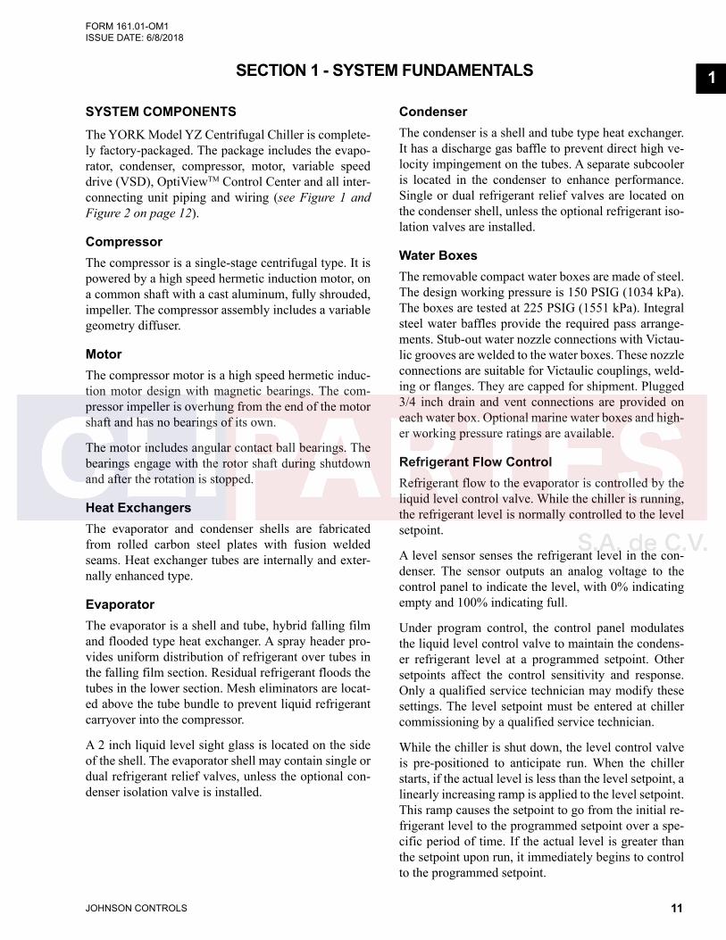
SYSTEM COMPONENTSThe YORK Model YZ Centrifugal Chiller is complete-ly factory-packaged. The package includes the evapo-rator, condenser, compressor, motor, variable speed drive (VSD), OptiViewTM Control Center and all inter-connecting unit piping and wiring (see Figure 1 and Figure 2 on page 12).
CompressorThe compressor is a single-stage centrifugal type. It is powered by a high speed hermetic induction motor, on a common shaft with a cast aluminum, fully shrouded, impeller. The compressor assembly includes a variable geometry diffuser.
MotorThe compressor motor is a high speed hermetic induc-tion motor design with magnetic bearings. The com-pressor impeller is overhung from the end of the motor shaft and has no bearings of its own.
The motor includes angular contact ball bearings. The bearings engage with the rotor shaft during shutdown and after the rotation is stopped.
Heat ExchangersThe evaporator and condenser shells are fabricated from rolled carbon steel plates with fusion welded seams. Heat exchanger tubes are internally and exter-nally enhanced type.
EvaporatorThe evaporator is a shell and tube, hybrid falling film and flooded type heat exchanger. A spray header pro-vides uniform distribution of refrigerant over tubes in the falling film section. Residual refrigerant floods the tubes in the lower section. Mesh eliminators are locat-ed above the tube bundle to prevent liquid refrigerant carryover into the compressor.
A 2 inch liquid level sight glass is located on the side of the shell. The evaporator shell may contain single or dual refrigerant relief valves, unless the optional con-denser isolation valve is installed.
CondenserThe condenser is a shell and tube type heat exchanger. It has a discharge gas baffle to prevent direct high ve-locity impingement on the tubes. A separate subcooler is located in the condenser to enhance performance. Single or dual refrigerant relief valves are located on the condenser shell, unless the optional refrigerant iso-lation valves are installed.
Water BoxesThe removable compact water boxes are made of steel. The design working pressure is 150 PSIG (1034 kPa). The boxes are tested at 225 PSIG (1551 kPa). Integral steel water baffles provide the required pass arrange-ments. Stub-out water nozzle connections with Victau-lic grooves are welded to the water boxes. These nozzle connections are suitable for Victaulic couplings, weld-ing or flanges. They are capped for shipment. Plugged 3/4 inch drain and vent connections are provided on each water box. Optional marine water boxes and high-er working pressure ratings are available.
Refrigerant Flow ControlRefrigerant flow to the evaporator is controlled by the liquid level control valve. While the chiller is running, the refrigerant level is normally controlled to the level setpoint.
A level sensor senses the refrigerant level in the con-denser. The sensor outputs an analog voltage to the control panel to indicate the level, with 0% indicating empty and 100% indicating full.
Under program control, the control panel modulates the liquid level control valve to maintain the condens-er refrigerant level at a programmed setpoint. Other setpoints affect the control sensitivity and response. Only a qualified service technician may modify these settings. The level setpoint must be entered at chiller commissioning by a qualified service technician.
While the chiller is shut down, the level control valve is pre-positioned to anticipate run. When the chiller starts, if the actual level is less than the level setpoint, a linearly increasing ramp is applied to the level setpoint. This ramp causes the setpoint to go from the initial re-frigerant level to the programmed setpoint over a spe-cific period of time. If the actual level is greater than the setpoint upon run, it immediately begins to control to the programmed setpoint.
1
JOHNSON CONTROLS12
FORM 161.01-OM1 ISSUE DATE: 6/8/2018SECTION 1 - SYSTEM FUNDAMENTALS
LD22373
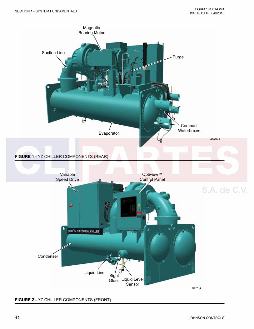
Suction Line
Magnetic Bearing Motor
Purge
Compact WaterboxesEvaporator
FIGURE 1 - YZ CHILLER COMPONENTS (REAR)
LD22514
Variable Speed Drive
Optiview™ Control Panel
Liquid Level Sensor
Sight Glass
Liquid Line
Condenser
FIGURE 2 - YZ CHILLER COMPONENTS (FRONT)

JOHNSON CONTROLS 13
SECTION 1 - SYSTEM FUNDAMENTALSFORM 161.01-OM1 ISSUE DATE: 6/8/2018
1Variable Speed DriveThe Variable Speed Drive is factory packaged with the chiller. It is designed to vary the compressor motor speed by controlling the frequency and voltage of the electrical power to the motor. The control logic auto-matically adjusts motor speed as required to suit lift and capacity requirements. The VSD is connected to an OptiView Control center. The VSD and OptiView communicate using a Modbus communication proto-col.
Optional Service Isolation ValvesIf the chiller is equipped with optional service isolation valves on the discharge and liquid line. These valves are used for isolating the refrigerant charge in either the evaporator or condenser to allow service access to the system and must remain open during operation. A refrigerant pump-out unit will be required to isolate the refrigerant.
Isolation of the refrigerant in this system must be performed by a qualified service technician.
Optional Hot Gas BypassHot gas bypass is optional and is used to provide great-er turndown than otherwise available for load and head conditions. The OptiView Control Center will auto-matically modulate the hot gas valve open and closed as required. Adjustment of the hot gas control valve must only be performed by a qualified service techni-cian.
LD26720
52
41
087 9
36
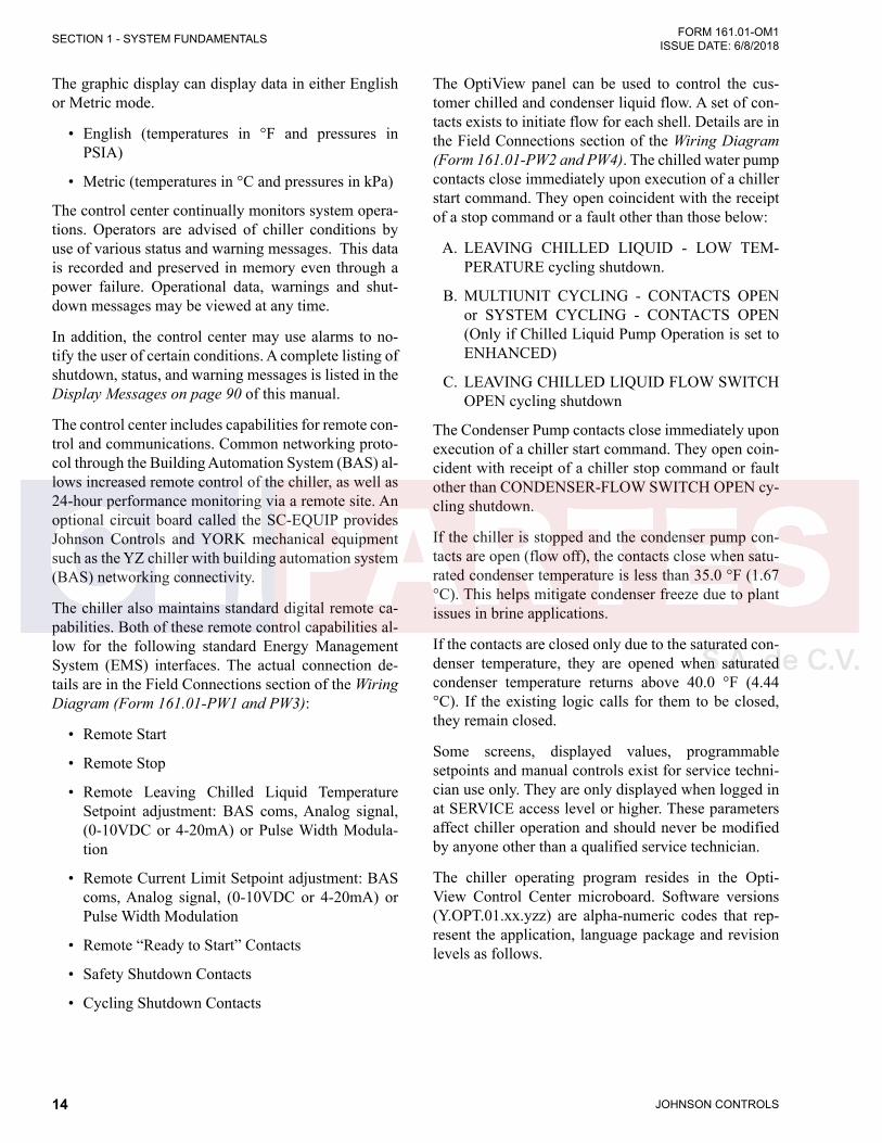
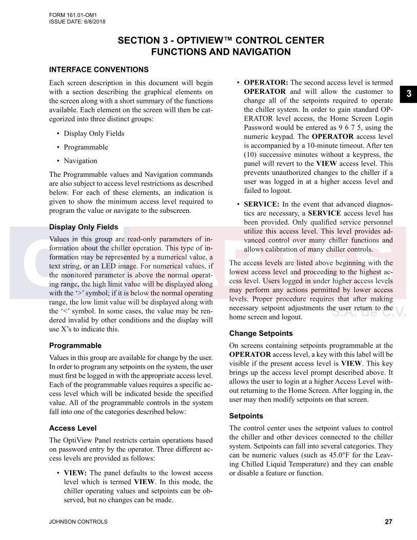
FIGURE 3 - OPTIVIEW CONTROL CENTER
OptiView Control CenterThe YORK OptiView™ control center LCD graphic display and keypad is the interface for starting, stop-ping, configuring, monitoring, and commanding the chiller. The control center is a microprocessor based system designed for centrifugal chillers. It controls the LCHLT (leaving chilled liquid temperature) and main-tains safe operation of the chiller.
The display allows for the presentation of operating pa-rameters and can trend data to present a graphical rep-resentation of both present and historical operation of the chiller. The locations of various chiller parameters are clearly and intuitively marked. Instructions for spe-cific operations are provided on many of the screens. The screens and navigation are shown in "SECTION 3 - OPTIVIEW™ CONTROL CENTER FUNCTIONS AND NAVIGATION".
Eight buttons are available on the right side of the pan-el, which are primarily used for navigation between the system screens. At the base of the display are 6 ad-ditional buttons. The button functions are redefined based on the currently displayed screen. The area to the right of the keypad is used for data entry. A stan-dard numeric keypad is provided for entry of system setpoints and limits.
The Decimal key provides accurate entry of setpoint values.
A +/- key has also been provided to allow entry of negative values and AM/PM selection dur-ing time entry.
In order to accept changes made to the chiller setpoints, the Check key is provided as a uni-versal ‘Enter’ key or ‘Accept’’ symbol.
In order to reject entry of a setpoint or dismiss an entry form, the ‘X’ key is provided as a uni-versal ‘Cancel’ symbol.
Cursor Arrow keys are provid-ed to allow movement on screens which contain a large amount of entry data. In addi-tion, these keys can be used to scroll through history and event logs.
1
JOHNSON CONTROLS14
FORM 161.01-OM1 ISSUE DATE: 6/8/2018SECTION 1 - SYSTEM FUNDAMENTALS
The graphic display can display data in either English or Metric mode.
• English (temperatures in °F and pressures in PSIA)
• Metric (temperatures in °C and pressures in kPa)
The control center continually monitors system opera-tions. Operators are advised of chiller conditions by use of various status and warning messages. This data is recorded and preserved in memory even through a power failure. Operational data, warnings and shut-down messages may be viewed at any time.
In addition, the control center may use alarms to no-tify the user of certain conditions. A complete listing of shutdown, status, and warning messages is listed in the Display Messages on page 90 of this manual.
The control center includes capabilities for remote con-trol and communications. Common networking proto-col through the Building Automation System (BAS) al-lows increased remote control of the chiller, as well as 24-hour performance monitoring via a remote site. An optional circuit board called the SC-EQUIP provides Johnson Controls and YORK mechanical equipment such as the YZ chiller with building automation system (BAS) networking connectivity.
The chiller also maintains standard digital remote ca-pabilities. Both of these remote control capabilities al-low for the following standard Energy Management System (EMS) interfaces. The actual connection de-tails are in the Field Connections section of the Wiring Diagram (Form 161.01-PW1 and PW3):
• Remote Start
• Remote Stop
• Remote Leaving Chilled Liquid Temperature Setpoint adjustment: BAS coms, Analog signal, (0-10VDC or 4-20mA) or Pulse Width Modula-tion
• Remote Current Limit Setpoint adjustment: BAS coms, Analog signal, (0-10VDC or 4-20mA) or Pulse Width Modulation
• Remote “Ready to Start” Contacts
• Safety Shutdown Contacts
• Cycling Shutdown Contacts
The OptiView panel can be used to control the cus-tomer chilled and condenser liquid flow. A set of con-tacts exists to initiate flow for each shell. Details are in the Field Connections section of the Wiring Diagram (Form 161.01-PW2 and PW4). The chilled water pump contacts close immediately upon execution of a chiller start command. They open coincident with the receipt of a stop command or a fault other than those below:
A. LEAVING CHILLED LIQUID - LOW TEM-PERATURE cycling shutdown.
B. MULTIUNIT CYCLING - CONTACTS OPEN or SYSTEM CYCLING - CONTACTS OPEN (Only if Chilled Liquid Pump Operation is set to ENHANCED)
C. LEAVING CHILLED LIQUID FLOW SWITCH OPEN cycling shutdown
The Condenser Pump contacts close immediately upon execution of a chiller start command. They open coin-cident with receipt of a chiller stop command or fault other than CONDENSER-FLOW SWITCH OPEN cy-cling shutdown.
If the chiller is stopped and the condenser pump con-tacts are open (flow off), the contacts close when satu-rated condenser temperature is less than 35.0 °F (1.67 °C). This helps mitigate condenser freeze due to plant issues in brine applications.
If the contacts are closed only due to the saturated con-denser temperature, they are opened when saturated condenser temperature returns above 40.0 °F (4.44 °C). If the existing logic calls for them to be closed, they remain closed.
Some screens, displayed values, programmable setpoints and manual controls exist for service techni-cian use only. They are only displayed when logged in at SERVICE access level or higher. These parameters affect chiller operation and should never be modified by anyone other than a qualified service technician.
The chiller operating program resides in the Opti-View Control Center microboard. Software versions (Y.OPT.01.xx.yzz) are alpha-numeric codes that rep-resent the application, language package and revision levels as follows.

JOHNSON CONTROLS 15
SECTION 1 - SYSTEM FUNDAMENTALSFORM 161.01-OM1 ISSUE DATE: 6/8/2018
1• Y – Commercial Chiller 03630 Microboard
• OPT - OptiView
• 01 – YZ Mod A Chiller
• xx - Controls Revision level (00, 01, etc)
• y – Language Package (0=English only, 1=NEMA, 2=CE, 3=NEMA/CE )
• zz – Language Package Revision level (00, 01, etc)
Each time the controls portion or language section is revised, the respective revision level increments.Soft-ware upgrades should only be performed by a service technician.
SYSTEM OPERATIONIn operation, a liquid to be chilled (water or brine) flows through the evaporator tubes, where its heat is transferred to low pressure liquid refrigerant sprayed over and pooled outside the tubes, boiling the refriger-ant. The chilled liquid is then piped to air conditioning or process terminal units, absorbing heat. The warmed liquid is then returned to the chiller to complete the chilled liquid circuit cycle.
The refrigerant vapor, which is produced by the boiling action in the evaporator, is drawn into the suction of the compressor where the rotating impeller increases its pressure and temperature and discharges it into the condenser. The cooling fluid flowing through the con-denser tubes absorbs heat from the refrigerant vapor, causing it to condense. The cooling fluid is supplied to the chiller from an external source, usually a cooling tower. The condensed refrigerant drains from the con-denser into the subcooler section. There, it is cooled by the entering condenser water and exits to into the liq-uid return line. The level control valve meters the flow of liquid refrigerant to the evaporator to complete the refrigerant circuit. The level control valve continually adjusts position as load changes to meet the changed mass flow rate of refrigerant required to keep the sys-tem balanced. It does this by maintaining a constant level in the condenser, enough to maintain a liquid seal to the outlet.
Capacity ControlThe major components of a chiller are selected to handle the required refrigerant flow at full load design conditions. However, most systems will be called upon to deliver full load capacity for only a relatively small part of the time the unit is in operation.
The speed at which the compressor rotates establishes the pressure differential that the chiller can operate against. This is referred to as ‘lift’. Speed must always be maintained above the minimum necessary to create the lift required for the pressure difference between the condenser and evaporator, regardless of load. Below that speed, gas surge occurs. That pressure difference is a function of the LCHLT and the leaving condenser liquid temperature and the heat transfer between those liquids and the refrigerant.
Reduced speed also reduces the available capacity of the chiller. If speed is reduced, chiller power use is reduced. Therefore, at reduced capacity requirements where condenser pressure is also reduced, the motor speed is reduced as much as possible while maintain-ing chilled liquid temperature and sufficient lift. When the speed cannot be further reduced due to lift required for the specified leaving chilled water temperature set-ting and available cooling to the condenser and capac-ity must be further reduced, a mechanism called the Variable Geometry Diffuser (VGD) at the exit of the impeller is used to reduce refrigerant gas flow. The VGD not only controls capacity, but serves to mitigate “stall.” Stall is an effect caused by slow refrigerant gas passing through the compressor at reduced flow rates needed for low capacity operation.
A final optional means to reduce capacity called Hot Gas Bypass (HGBP) is available regardless of com-pressor model. When selected for an application, HGBP is used to re-circulate some refrigerant through the compressor without using it for cooling the chilled liquid. Although this does not reduce power consump-tion, it greatly reduces the capacity of the chiller for maximum turndown. The YZ uses these mechanisms in a controlled order to maintain the best possible ef-ficiency.
The YZ Chiller controls capacity by adjusting the com-pressor VGD position, the compressor motor Variable Speed Drive (VSD), and optional Hot Gas Bypass valve (HGBP) position (if equipped) in a specific se-quence depending on whether loading or unloading is required to keep LCHLT at setpoint. Motor speed is additionally and simultaneously adjusted as necessary to maintain the minimum compressor lift required to prevent surge. The sequence for operation of the con-trol devices is as follows:
JOHNSON CONTROLS16
FORM 161.01-OM1 ISSUE DATE: 6/8/2018SECTION 1 - SYSTEM FUNDAMENTALS
• Conditions require capacity increase:
1. HGBP (if present) is driven toward closed.
2. When the HGBP is full closed, the VGD is driven toward open.
3. When the VGD is fully opened, VSD speed is increased.
• Conditions require capacity decrease:
1. VSD speed is decreased.
2. When VSD speed is at the minimum limit to avoid surge, the VGD is driven toward closed.
3. When the VGD reaches closed, the HGBP (if present) is driven toward open.
Also, high condenser pressure, low evaporator pres-sure, high motor current, and high input current limits and overrides limit or reduce the output to the appro-priate devices (HGBP, VGD, or VSD) to mitigate the condition to keep the chiller online. As any of these physical thresholds are approached, the control will proportionally limit the amount of capacity increase permitted and if exceeded will issue unloading into the capacity control command.
Anti-Surge Minimum FrequencyIn order to maintain sufficient compressor lift to over-come condenser pressure and prevent surge through-out operation, the control maintains and continuously updates a minimum limit for VSD speed. This limit is the Active Anti-Surge Minimum Frequency. It is calcu-lated and applied to the speed each cycle of the capac-ity control routine.
Surge ProtectionThe surge protection feature detects surge events. It provides a running count of the surges detected over the lifetime of the chiller. It allows the user to define how many surges are excessive and how the control will react to an excess surge condition. When exces-sive surging is detected, this feature can shutdown the chiller.
Surge events are detected by monitoring the relation-ship between the Condenser pressure and Evaporator pressure while the chiller is running. An excess surge condition is detected by comparing the number of surge events that occur in a selectable time period to a selectable threshold.
If the number of surge events (Surge Window Count) detected in the time period programmed as the COUNT WINDOW setpoint (1 to 5 minutes; default 3) exceeds the threshold programmed as the COUNT LIMIT setpoint (4 to 20; default 15) an excess surge condition has been detected.
Unless the SHUTDOWN features have been enabled as explained below, the chiller will continue running under the same conditions displaying WARNING – EXCESS SURGE DETECTED. This message will be displayed until manually reset with the Warning Re-set key in Operator access level. If the SHUTDOWN setpoint is Enabled when an excess surge condition has been detected, a safety shutdown will be performed and SURGE PROTECTION - EXCESS SURGE is displayed.
Head Pressure ControlThe Head Pressure Control feature enables chiller control of a field-mounted facility condenser water temperature control means, if one is necessary for pro-longed cold water startup as described in SECTION 3 - OPTIVIEW™ CONTROL CENTER FUNCTIONS AND NAVIGATION. YZ chillers are capable of op-eration within a wide range of condenser water tem-peratures; however, a low minimum condenser water temperature, as specified in the YZ Engineering Guide (Form 161.01-EG1), is required to maintain a suffi-cient pressure differential (head) between the condens-er and evaporator for proper refrigerant management in the chiller. The head pressure control function pro-vides an analog output control signal from the OptiV-iew Control Center that responds to the programmed head pressure (condenser pressure minus evaporator pressure) Setpoint. The 0-10VDC or 4-20mA output is configurable from the Head Pressure Control screen when the feature is enabled. Output wiring is described in Unit Wiring and Field Connections for YZ Cen-trifugal Chiller with Magnetic Bearing Control (Form 161.01-PW4).

JOHNSON CONTROLS 17
SECTION 1 - SYSTEM FUNDAMENTALSFORM 161.01-OM1 ISSUE DATE: 6/8/2018
1WATER CIRCUITS
Flow RateFor normal water chilling duty, the flow rates are per-mitted at water velocity levels within the heat exchang-er tubes between 0.91m/s and 3.66m/s (3.0 fps and 12.0 fps) for evaporators and 1.0m/s and 3.66m/s (3.3 fps and 12.0 fps) for condensers. Two pass units are also limited to 134kPa (45ft H2O) water pressure drop. The three pass limit is 201kPa (67.5ft H2O). Variable flow in the condenser is not recommended, as it gen-erally raises the energy consumption of the system by keeping the condenser pressure high in the chiller. Additionally, the rate of fouling in the condenser will increase at lower water velocities associated with vari-able flow, raising system maintenance costs. Cooling towers typically have narrow ranges of operation with respect to flow rates, and will be more effective with full design flow.
Chillers can tolerate a 50% flow rate change in one minute that is typically associated with the staging of an additional chiller. A lower flow rate change is used for better system stability and set point control. Proper sequencing via the building automation system will make this a very smooth transition.
Variable Primary FlowTypically, the Variable Primary Flow (VPF) systems are utilized in large chilled water plants, as VPF sys-tems can offer lower installation and operating costs, but require sophisticated control and flow monitor-ing. YZ chillers operate successfully in VPF systems. With a minimum allowable evaporator tube velocity of 0.5m/s (1.5 fps) for standard tubes at part load rating conditions, YZ chillers accommodate the wide varia-tion in flow required by many chilled water VPF ap-plications.
Temperature RangesFor normal water chilling duty, leaving chilled water temperatures may range between 3.5°C (38°F) and 21.0°C (70°F), to obtain temperature deltas between entering chilled water temperatures and leaving chilled water temperatures of 1.7°C to 16.7°C (3°F to 30°F).
Water QualityWater quality may affect the performance of any chill-er through corrosion, deposition of heat-resistant scale, sedimentation or organic growth. These will degrade the chiller's performance and increase operating and maintenance costs. The quality of the water supply for
the condenser and evaporator must be analyzed by a water treatment specialist for practical and economical liquid chiller applications. Typically, corrective water treatment and periodic cleaning of tubes maintains a chiller's performance. If water conditions exist which cannot be corrected by proper water treatment, it may be necessary to provide a larger allowance for fouling, and/or to specify special materials of construction.
General PipingAll chilled water and condenser water piping is de-signed, and should be installed in accordance with, ap-proved piping practices.
• Chilled water pump and condenser water pumps should be located to discharge through the chiller to assure positive pressure and flow.
• Piping should include offsets to provide flexibility and be arranged to prevent drainage of water from the evaporator and condenser when the pumps are shut off.
• Piping should be adequately supported and braced independently of the chiller to avoid strain on chiller components.
• Hangers must allow for alignment of the pipe. Iso-lators in piping and in the hangers are highly de-sirable in achieving sound and vibration control.
• Piping should be arranged for ease of disassem-bly at the unit for tube cleaning. All water piping should be thoroughly cleaned of all dirt and debris before final connections are made to the chiller.
Vents and Drain ValvesThe following precautions may be taken to improve chiller performance and maintenance.
• Evaporator and condenser waterboxes are equipped with plugged vent and drain connec-tions.
• If desired, vent and drain valves maybe installed with or without piping to open drain.
• Pressure gauge equipped with stop-clocks and stop-valves maybe installed in the intelts and out-lets of the condenser and chilled water lines, both places as close as possible to the chiller. An over-hear monorail maybe used to facilitate servicing.
JOHNSON CONTROLS18
FORM 161.01-OM1 ISSUE DATE: 6/8/2018SECTION 1 - SYSTEM FUNDAMENTALS
ConnectionsThe standard YZ chiller unit is designed for 1034 kPa (150 PSIG) working pressure in both, chilled water circuits and condenser water circuits. The wa-ter nozzle connections to these circuits are furnished with grooves standardized to ANSI/AWWA C-606 for shoulder joints. All water piping should be thoroughly cleaned of all dirt and debris before final connections are made to the chiller.
Chilled WaterA water strainer of maximum 3.2 mm (1/8") perfo-rated holes must be field-installed in the chilled water inlet line as close as possible to the chiller such that the chilled water pump is protected by the strainer. The strainer is important to protect the chiller from debris or objects which could block flow through individu-al heat exchanger tubes. A reduction in flow through tubes could seriously impair the chiller performance or even result in tube freeze-up. A flow switch is factory installed in the evaporator nozzle and connected to the OptiView panel, which assures adequate chilled water flow during operation.
Condenser WaterThe chiller is engineered for maximum efficiency at both design and part load operation by taking advan-tage of the colder cooling tower water temperatures which occur during winter. Appreciable power sav-ings are realized from these reduced heads. At initial startup, entering condensing water temperature may be 16.7°C (30°F) colder than the standby chilled water temperature.

JOHNSON CONTROLS 19
SECTION 1 - SYSTEM FUNDAMENTALSFORM 161.01-OM1 ISSUE DATE: 6/8/2018
1
LD26721
1 2
3
11
12
13
9
8
YZMAGNETIC BEARINGCENTRIFUGAL CHILLER
029-27711-000 REV-
10
7
5
4
6
REFRIGERANT STATESHigh Pressure Vapor
Low Pressure Vapor
High Pressure Liquid Refrigerant
Low Pressure Liquid Refrigerant
1 Compressor
2 Optional Hot Gas By-pass Valve
3 Suction Line
4 Evaporator
5 Falling Film Hood
6 Liquid Line
7 Sub-Cooler
8 Condenser
9 Optional Isolation Valve
10 Nameplate
11 Optiview
12 Discharge Line
13 Variable Speed Drive (VSD)
FIGURE 4 - REFRIGERANT FLOW-THRU CHILLER
JOHNSON CONTROLS20
FORM 161.01-OM1 ISSUE DATE: 6/8/2018SECTION 1 - SYSTEM FUNDAMENTALS
THIS PAGE INTENTIONALLY LEFT BLANK.

JOHNSON CONTROLS 21
FORM 161.01-OM1 ISSUE DATE: 6/8/2018
2
SECTION 2 - SYSTEM OPERATING PROCEDURES
PRE-STARTINGPrior to starting the chiller, the display should read "SYSTEM READY TO START."
The Panel can only boot up when line power is avail-able to the VSD transformers and the UPS battery is present and connected with its disconnect closed.
After periods of waterside maintenance or prolonged shutdown, vent any air from the chiller water boxes prior to starting the water pumps. Failure to do so can result in pass baffle damage.
Condenser Water Temperature ControlThe YORK YZ chiller is designed to lower power con-sumption by taking advantage of lower than design temperatures that are naturally produced by cooling towers throughout the operating year. Exact control of condenser water, such as a cooling tower bypass, is not necessary for most installations.
At start-up, the entering condenser water tempera-ture may be as much as 30°F (16.66°C) colder than the standby return chilled water temperature. Cooling tower fan cycling will normally provide adequate con-trol of the entering condenser water temperature.
START-UPIf the chilled water and/or condenser water pumps are manually operated, start the pump. The control cen-ter will not allow the chiller to start unless chilled liq-uid flow is established through the unit. If the liquid pumps are wired to the microcomputer control center pump run contacts, the pump will automatically start, therefore, this step is not necessary.
The coolant temperature inside any JCI-supplied liquid-cooled motor starter must be maintained above the dewpoint tem-perature in the equipment room to prevent condensing water vapor inside the starter cabinet. An additional temperature-controlled throttle valve is needed in the flow path for the starter heat exchanger to regulate cooling above the equipment room dewpoint for applications using cooling sources other than evaporative air-exchange methods. The temperature control valve should be the type to open on increasing drive coolant temperature, fail-closed, and set for a temperature above dewpoint. It can be requested as factory-supplied by special quotation.
Start/stop control depends on whether the chiller con-trol source is set to Local or one of the Remote start types on the chiller Setup - Operations screen.
The chiller is started:
• By pressing the Start key on the Home Screen when the chiller is set to local mode.
• Remotely through digital input in hardwire re-mote mode by closing a contact between TB3-1 and TB3-7. The local keypad start key must be pressed initially to allow remote operation.
• Remotely by the SC-EQUIP in BAS remote mode. The local keypad start key must be pressed initially to allow remote operation.
In LOCAL control source pressing the START key on the home screen will immediately start the chiller. In remote ISN, ANALOG, DIGITAL, or MODEM, a re-mote start command must also be provided to the prop-er input connection.
When the control is changed to local mode from any other source, it will remain in RUN if already running or remain in STOP if already stopped. A hardware safe-ty stop button is located on the side of the panel to stop the chiller in an emergency situation.
2
JOHNSON CONTROLS22
FORM 161.01-OM1 ISSUE DATE: 6/8/2018SECTION 2 - SYSTEM OPERATING PROCEDURES
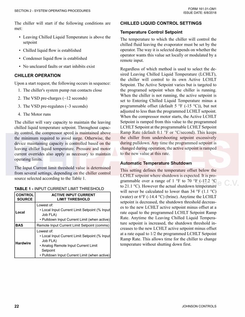
The chiller will start if the following conditions are met:
• Leaving Chilled Liquid Temperature is above the setpoint
• Chilled liquid flow is established
• Condenser liquid flow is established
• No uncleared faults or start inhibits exist
CHILLER OPERATIONUpon a start request, the following occurs in sequence:
1. The chiller's system pump run contacts close
2. The VSD pre-charges (~12 seconds)
3. The VSD pre-regulates (~3 seconds)
4. The Motor runs
The chiller will vary capacity to maintain the leaving chilled liquid temperature setpoint. Throughout capac-ity control, the compressor speed is maintained above the minimum required to avoid surge. Otherwise, the device maintaining capacity is controlled based on the leaving chiller liquid temperature. Pressure and motor current overrides also apply as necessary to maintain operating limits.
The Input Current limit threshold value is determined from several settings, depending on the chiller control source selected according to the Table 1.
TABLE 1 - INPUT CURRENT LIMIT THRESHOLDCONTROL SOURCE
ACTIVE INPUT CURRENT LIMIT THRESHOLD
Local
Lowest of: • Local Input Current Limit Setpoint (% Input
Job FLA) • Pulldown Input Current Limit (when active)
BAS Remote Input Current Limit Setpoint (comms)
Hardwire
Lowest of: • Local Input Current Limit Setpoint (% Input
Job FLA) • Analog Remote Input Current Limit
Setpoint • Pulldown Input Current Limit (when active)
CHILLED LIQUID CONTROL SETTINGS
Temperature Control SetpointThe temperature to which the chiller will control the chilled fluid leaving the evaporator must be set by the operator. The way it is selected depends on whether the operator wants this value set locally or modulated by a remote input.
Regardless of which method is used to select the de-sired Leaving Chilled Liquid Temperature (LCHLT), the chiller will control to its own Active LCHLT Setpoint. The Active Setpoint varies but is targeted to the programed setpoint when the chiller is running. When the chiller is not running, the active setpoint is set to Entering Chilled Liquid Temperature minus a programmable offset (default 5 °F (-15 °C)), but not adjusted to less than the programmed LCHLT setpoint. When the compressor motor starts, the Active LCHLT Setpoint is ramped from this value to the programmed LCHLT Setpoint at the programmable LCHLT Setpoint Ramp Rate (default 0.1 °F or °C/second). This keeps the chiller from undershooting setpoint excessively during pulldown. Any time the programmed setpoint is changed during operation, the active setpoint is ramped to the new value at this rate.
Automatic Temperature ShutdownThis setting defines the temperature offset below the LCHLT setpoint where shutdown is expected. It is pro-grammable over a range of 1 °F to 70 °F (-17.2 °C to 21.1 °C). However the actual shutdown temperature will never be calculated to lower than 34 °F (1.1 °C) (water) or 6°F (-14.4 °C) (brine). Anytime the LCHLT setpoint is decreased, the shutdown threshold decreas-es to the new LCHLT active setpoint minus offset at a rate equal to the programmed LCHLT Setpoint Ramp Rate. Anytime the Leaving Chilled Liquid Tempera-ture setpoint is increased, the shutdown threshold in-creases to the new LCHLT active setpoint minus offset at a rate equal to 1/2 the programmed LCHLT Setpoint Ramp Rate. This allows time for the chiller to change temperature without shutting down first.

JOHNSON CONTROLS 23
SECTION 2 - SYSTEM OPERATING PROCEDURESFORM 161.01-OM1 ISSUE DATE: 6/8/2018
2
Automatic Temperature RestartThis setting defines the temperature offset above the LCHLT setpoint where automatic restart is expected. It is programmable over a range of 0°F to 46 °F (-17.8 °C and 7.8 °C) varying with the LCHWT setpoint. How-ever, the restart temperature will never be calculated above 82°F. This setpoint can be used to reduce chiller cycling by delaying the chiller restart until the cooling load has increased sufficiently.
OPERATOR SETPOINTS QUICK REFERENCEThe most common Operator level setpoints can be found on the Setpoints screen or the following screens:
TABLE 3 - INPUT CURRENT LIMIT THRESHOLD
SCREEN NAME SETPOINT
Home > Evaporator Local Cooling Setpoint Temperature
Home > Evaporator Shutdown Temperature Offset
Home > Evaporator Restart Temperature Offset
Home > Motor Local Motor Current LimitHome > Motor Pulldown Demand LimitHome > Motor Pulldown Demand TimeHome > Condenser > Head Pressure Control Head Pressure Control
2
TABLE 2 - TEMPERATURE SETPOINT
CONTROL SOURCE
LEAVING CHILLED LIQUID TEMPERATURE SETPOINT
LocalLocal Leaving Chilled Liquid Temperature Setpoint, entered from the panel. It is programmable over the range of 36.0°F to 72.0°F (2.2°C to 22.2 °C) (water) or 10.0°F to 72.0°F (-12.2 °C to 22.2 °C) (brine).
Building Automation Systems (BAS)
Remote Leaving Chilled Liquid Temperature Setpoint value sent over communications 36.0°F to 72.0°F (2.2°C to 22.2 °C) (water) or 10.0°F to 72.0°F (-12.2 °C to 22.2 °C) (brine). If nothing is written to the address, the default is 45 °F (7.2 °C).
Hardwire
The Remote Setpoint Minimum is user selectable at the Operator password level between 0.0°F and 200.0°F (-17.8 °C and 93.3 °C) (default = 0.0°F (-17.8 °C)). The Remote Setpoint Maximum is also user selectable between 0.0°F and 200.0°F (-17.8 °C and 93.3 °C) (default = 100.0°F (37.8 °C)). The Setpoint will vary over the range selected by the Min and Max by the proportion of the Hardwire Analog 0 to 10VDC or 4 to 20mA signal from the BAS controller. For example: with the Min set to 40 and the Max to 60 and the BAS 0 to 10VDC control signal sending a 5VDC signal, the Selected Cooling Setpoint will be 50.0°F (10 °C).
Pulse Width Modulation (PWM)
The Remote Setpoint Minimum is user selectable at the Operator password level between 0.0°F and 200.0°F (-17.8 °C and 93.3 °C) (default = 0.0°F (-17.8 °C)). The Remote Setpoint Maximum is also user selectable between 0.0°F and 200.0°F (-17.8 °C and 93.3 °C) (default = 100.0°F (37.8 °C)). The Setpoint will vary over the range selected by the Min and Max by the proportion of the timed 1 to 11 second pulse. For example: with the Min set to 40 and the Max to 60 and the BAS closing a contact between TB3-19 and TB3-1 for 6 seconds, the Selected Cooling Setpoint will be 50.0°F (10 °C).The PWM input is in the form of a 1 to 11 second relay contact closure that applies 115VAC to the I/O Board TB3-19 for 1 to 11 seconds. A contact closure time (pulse width) of 1 second produces a 0°F offset form the Min Setpoint. An 11 second closure produces the maximum offset. The relay contacts should close for 1 to 11 seconds at least once every 30 minutes to maintain the setpoint to the desired value. If a 1 to 11 second closure is not received within 30 minutes of the last closure, the setpoint reverts to the Min setpoint valve. A closure is only accepted at rates not to exceed once every 70 sec-onds
JOHNSON CONTROLS24
FORM 161.01-OM1 ISSUE DATE: 6/8/2018SECTION 2 - SYSTEM OPERATING PROCEDURES
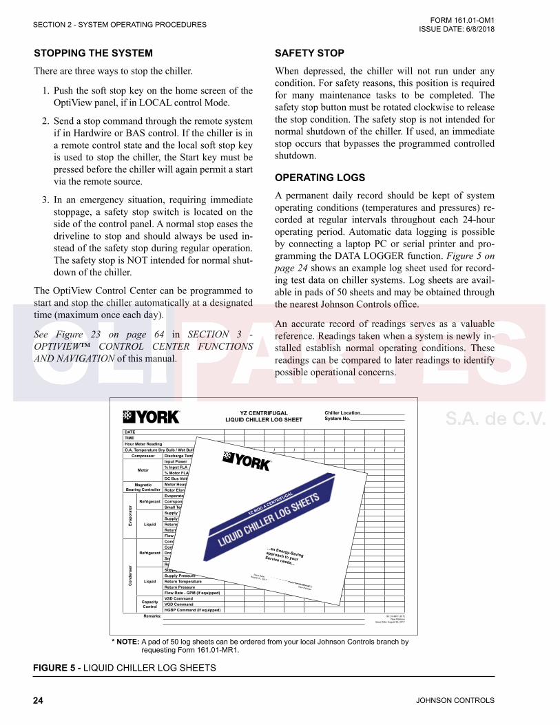
FIGURE 5 - LIQUID CHILLER LOG SHEETS
DATETIMEHour Meter ReadingO.A. Temperature Dry Bulb / Wet Bulb / / / / / / / / /
Compressor Discharge Temperature
Motor
Input Power% Input FLA% Motor FLADC Bus Voltage
Magnetic Bearing Controller
Motor Housing TemperatureRotor Elongation
Evap
orat
or
RefrigerantEvaporator PressureCorrsponding TemperatureSmall Temperature Difference
Liquid
Supply TemperatureSupply PressureReturn TemperatureReturn PressureFlow Rate - GPM (If equipped)
Con
dens
er
Refrigerant
Condenser PressureCorresponding TemperatureDrop Leg TemperatureSmall Temperature DifferenceRefrigerant Level
Liquid
Supply TemperatureSupply PressureReturn TemperatureReturn PressureFlow Rate - GPM (If equipped)
Capacity Control
VSD CommandVGD CommandHGBP Command (If equipped)
Remarks: 161.01-MR1 (817) New Release
Issue Date: August 30, 2017
YZ CENTRIFUGALLIQUID CHILLER LOG SHEET
Chiller Location System No.
Form 161.01-MR1 (817) New Release
Issue Date:August 31, 2017
...an Energy-Savingapproach to your Service needs...
YZ MOD A CENTRIFUGAL
* NOTE: A pad of 50 log sheets can be ordered from your local Johnson Controls branch by requesting Form 161.01-MR1.
STOPPING THE SYSTEMThere are three ways to stop the chiller.
1. Push the soft stop key on the home screen of the OptiView panel, if in LOCAL control Mode.
2. Send a stop command through the remote system if in Hardwire or BAS control. If the chiller is in a remote control state and the local soft stop key is used to stop the chiller, the Start key must be pressed before the chiller will again permit a start via the remote source.
3. In an emergency situation, requiring immediate stoppage, a safety stop switch is located on the side of the control panel. A normal stop eases the driveline to stop and should always be used in-stead of the safety stop during regular operation. The safety stop is NOT intended for normal shut-down of the chiller.
The OptiView Control Center can be programmed to start and stop the chiller automatically at a designated time (maximum once each day).
See Figure 23 on page 64 in SECTION 3 - OPTIVIEW™ CONTROL CENTER FUNCTIONS AND NAVIGATION of this manual.
SAFETY STOPWhen depressed, the chiller will not run under any condition. For safety reasons, this position is required for many maintenance tasks to be completed. The safety stop button must be rotated clockwise to release the stop condition. The safety stop is not intended for normal shutdown of the chiller. If used, an immediate stop occurs that bypasses the programmed controlled shutdown.
OPERATING LOGSA permanent daily record should be kept of system operating conditions (temperatures and pressures) re-corded at regular intervals throughout each 24-hour operating period. Automatic data logging is possible by connecting a laptop PC or serial printer and pro-gramming the DATA LOGGER function. Figure 5 on page 24 shows an example log sheet used for record-ing test data on chiller systems. Log sheets are avail-able in pads of 50 sheets and may be obtained through the nearest Johnson Controls office.
An accurate record of readings serves as a valuable reference. Readings taken when a system is newly in-stalled establish normal operating conditions. These readings can be compared to later readings to identify possible operational concerns.
JOHNSON CONTROLS 25
SECTION 2 - SYSTEM OPERATING PROCEDURESFORM 161.01-OM1 ISSUE DATE: 6/8/2018
2
For example, an increase in condenser approach tem-perature (condenser temperature minus leaving con-denser water temperature) may be an indication of dirty condenser tubes.
FAULT SHUTDOWNSThe chiller is programmed to shut down on two types of fault conditions.
• A Cycling fault will allow the chiller to automati-cally restart when the condition clears.
• A Safety fault requires the cause for the condition be determined and resolved before restarting.
To restart, all safety faults must be cleared by pressing the Clear Faults key on the Home screen. The chiller will restart unless the local Stop key is pressed or the remote run command has ceased.
PROLONGED SHUTDOWNIf the chiller is to be shut down for an extended period of time, such as over the winter season, the following procedure should be followed.
1. Test all system joints for refrigerant leaks with a leak detector.
• If any leaks are found, they should be re-paired before allowing the system to stand for a long period of time.
2. During long idle periods, the tightness of the sys-tem should be checked periodically.
3. If freezing temperatures could be encountered while the system is idle, drain the cooling water from the cooling tower, condenser and condenser pump.
4. Drain the chilled water system, chilled water pump and coils.
5. Open the drains on the evaporator.
6. Open the condenser liquid heads to assure com-plete drainage.
7. Drain the Variable Speed Drive cooling system.
8. Open the main disconnect switches to the VSD, condenser water pump and the chilled water pump.
9. Open the battery disconnect.
10. Ensure the control center is powered off.
RESTART AFTER PROLONGED SHUTDOWN1. Close all drain valves.
2. Close the battery disconnect switch.
3. Restore power to the control panel so that the UPS can charge the battery for at least eight hours pri-or to the planned start-up. The chiller has a start inhibit setting for if the battery voltage is below 12.8VDC.

JOHNSON CONTROLS26
FORM 161.01-OM1 ISSUE DATE: 6/8/2018SECTION 2 - SYSTEM OPERATING PROCEDURES
THIS PAGE INTENTIONALLY LEFT BLANK.
JOHNSON CONTROLS 27
FORM 161.01-OM1 ISSUE DATE: 6/8/2018
3
SECTION 3 - OPTIVIEW™ CONTROL CENTER FUNCTIONS AND NAVIGATION
INTERFACE CONVENTIONSEach screen description in this document will begin with a section describing the graphical elements on the screen along with a short summary of the functions available. Each element on the screen will then be cat-egorized into three distinct groups:
• Display Only Fields
• Programmable
• Navigation
The Programmable values and Navigation commands are also subject to access level restrictions as described below. For each of these elements, an indication is given to show the minimum access level required to program the value or navigate to the subscreen.
Display Only FieldsValues in this group are read-only parameters of in-formation about the chiller operation. This type of in-formation may be represented by a numerical value, a text string, or an LED image. For numerical values, if the monitored parameter is above the normal operat-ing range, the high limit value will be displayed along with the ‘>’ symbol; if it is below the normal operating range, the low limit value will be displayed along with the ‘<’ symbol. In some cases, the value may be ren-dered invalid by other conditions and the display will use X’s to indicate this.
ProgrammableValues in this group are available for change by the user. In order to program any setpoints on the system, the user must first be logged in with the appropriate access level. Each of the programmable values requires a specific ac-cess level which will be indicated beside the specified value. All of the programmable controls in the system fall into one of the categories described below:
Access LevelThe OptiView Panel restricts certain operations based on password entry by the operator. Three different ac-cess levels are provided as follows:
• VIEW: The panel defaults to the lowest access level which is termed VIEW. In this mode, the chiller operating values and setpoints can be ob-served, but no changes can be made.
• OPERATOR: The second access level is termed OPERATOR and will allow the customer to change all of the setpoints required to operate the chiller system. In order to gain standard OP-ERATOR level access, the Home Screen Login Password would be entered as 9 6 7 5, using the numeric keypad. The OPERATOR access level is accompanied by a 10-minute timeout. After ten (10) successive minutes without a keypress, the panel will revert to the VIEW access level. This prevents unauthorized changes to the chiller if a user was logged in at a higher access level and failed to logout.
• SERVICE: In the event that advanced diagnos-tics are necessary, a SERVICE access level has been provided. Only qualified service personnel utilize this access level. This level provides ad-vanced control over many chiller functions and allows calibration of many chiller controls.
The access levels are listed above beginning with the lowest access level and proceeding to the highest ac-cess level. Users logged in under higher access levels may perform any actions permitted by lower access levels. Proper procedure requires that after making necessary setpoint adjustments the user return to the home screen and logout.
Change SetpointsOn screens containing setpoints programmable at the OPERATOR access level, a key with this label will be visible if the present access level is VIEW. This key brings up the access level prompt described above. It allows the user to login at a higher Access Level with-out returning to the Home Screen. After logging in, the user may then modify setpoints on that screen.
SetpointsThe control center uses the setpoint values to control the chiller and other devices connected to the chiller system. Setpoints can fall into several categories. They can be numeric values (such as 45.0°F for the Leav-ing Chilled Liquid Temperature) and they can enable or disable a feature or function.

JOHNSON CONTROLS28
FORM 161.01-OM1 ISSUE DATE: 6/8/2018SECTION 3 - OPTIVIEW™ CONTROL CENTER FUNCTIONS AND NAVIGATION
Regardless of which setpoint is being programmed, the following procedure applies:
1. Press the desired setpoint key. A dialog box ap-pears displaying the present value, the upper and lower limits of the programmable range, and the default value.
2. If the dialog box begins with the word “ENTER”, use the numeric keys to enter the desired value. Leading zeroes are not necessary. If a decimal point is necessary, press the ‘•’ key.
Pressing the ▲ key, sets the entry value to the de-fault for that setpoint. Pressing the ▼ key, clears the present entry. The ◄ key is a backspace key and causes the entry point to move back one space.
If the dialog box begins with “SELECT”, use the ◄ and ► keys to select the desired value.
If the previously defined setpoint is desired, press the "X" (Cancel) key to dismiss the dialog box.
3. Press the "" (Enter) key.
If the value is within range, it is accepted and the dialog box disappears. The chiller will begin to operate based on the new programmed value. If out of range, the value will not be accepted and the user is prompted to try again.
Manual ControlsSome keys are used to perform manual control func-tions. These may involve manual control of items such as the compressor speed or valve actuators. These are typically restricted to qualified technicians in SER‑VICE access. Other keys in this category are used to initiate/terminate processes such as calibrations or re-ports.
Free CursorOn screens containing many setpoints, a specific “soft” key may not be assigned to each setpoint value. A soft key will be assigned to enable the cursor arrow keys below the numeric keypad which are used to “high-light” the desired setpoint field. At this point, the ‘’ key is pressed to bring up a dialog prompting the user to enter a new setpoint value. The ‘X’ key cancels cur-sor mode. (See the Schedule Screen for an example.)
NavigationIn order to maximize the number of values which the panel can display to the user, and to place those values in context, multiple screens have been designed to de-scribe the chiller operation. In order to move from one screen to the next, navigation keys have been defined. These keys allow the user to either move “forward” to a subscreen of the present screen, or move “backward” to the previous screen. Except for the home screen dis-play, the upper-right “soft” key will always return the user to the home screen. Navigating with “soft” keys is as simple as pressing the key next to the label contain-ing the name of the desired screen. The system will immediately refresh the display with the graphics for that screen. Following is a layout of all the screens and how they are connected.
Home Screen (Page page 30) System Screen (Page 32) Evaporator Screen (Page 34) Condenser Screen (Page 36) Compressor Screen (Page 40) Magnetic Bearing Controller Screen (Page 45) Surge Screen (Page 47) Variable Geometry Diffuser Screen (Page 49) Capacity Controls Screen (Page 42) VSD Screen (Page 54) VSD Details Screen (Page 56) Motor Details Screen (Page 50) Setpoints Screen (Page 60) Setup Screen (Page 62) Schedule Screen (Page 64) User Screen (Page 66) COMMS Screen (Page 67) Printer Screen (Page 68) Sales Order Screen (Page 70) Operations Screen (Page 72) History Screen (Page 74) History Details Screen (Page 76) Custom Screen (Page 77) Custom Setup Screen (Page 78) Trend Screen (Page 80) Trend Setup Screen (Page 82) Advanced Trend Setup Screen (Page 84) Common Slots Screen (Page 86)
JOHNSON CONTROLS 29
SECTION 3 - OPTIVIEW™ CONTROL CENTER FUNCTIONS AND NAVIGATIONFORM 161.01-OM1 ISSUE DATE: 6/8/2018
3
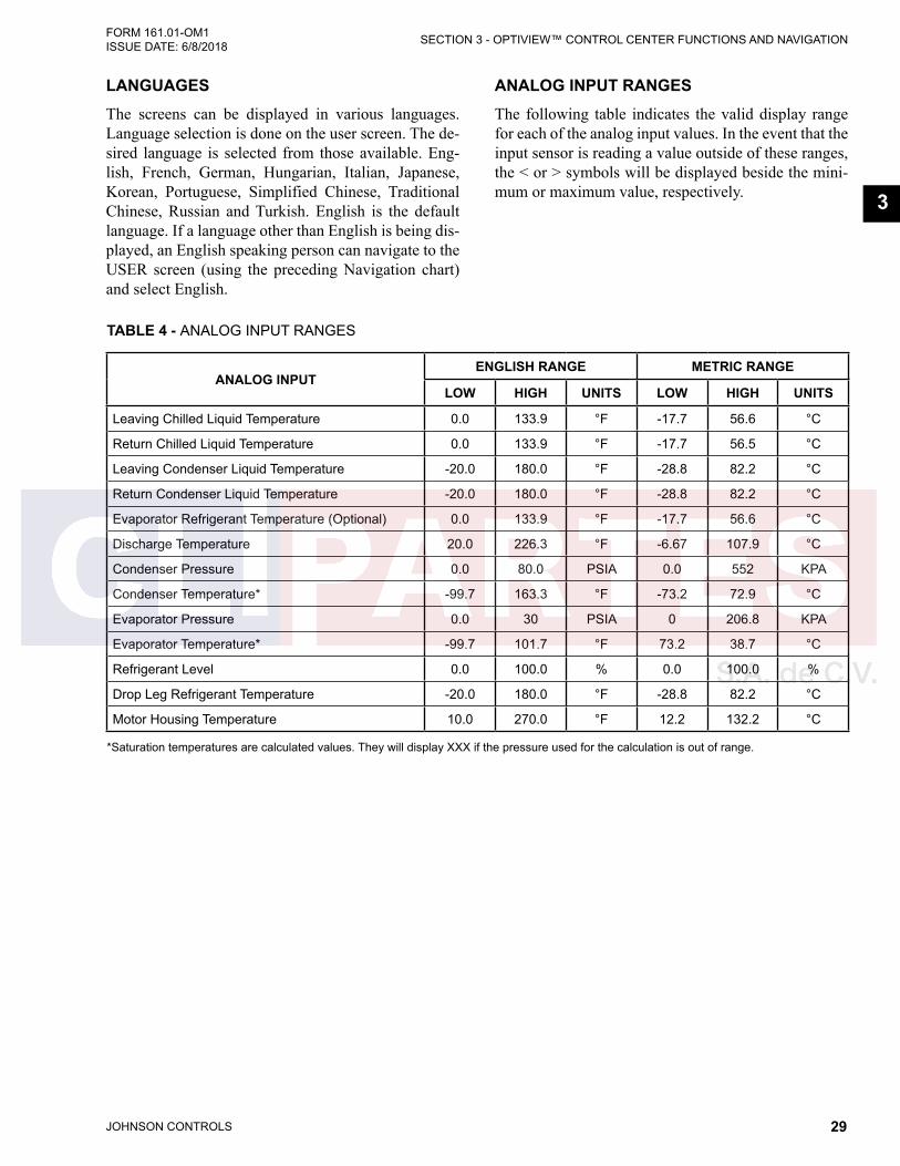
LANGUAGESThe screens can be displayed in various languages. Language selection is done on the user screen. The de-sired language is selected from those available. Eng-lish, French, German, Hungarian, Italian, Japanese, Korean, Portuguese, Simplified Chinese, Traditional Chinese, Russian and Turkish. English is the default language. If a language other than English is being dis-played, an English speaking person can navigate to the USER screen (using the preceding Navigation chart) and select English.
ANALOG INPUT RANGESThe following table indicates the valid display range for each of the analog input values. In the event that the input sensor is reading a value outside of these ranges, the < or > symbols will be displayed beside the mini-mum or maximum value, respectively.
TABLE 4 - ANALOG INPUT RANGES
ANALOG INPUTENGLISH RANGE METRIC RANGE
LOW HIGH UNITS LOW HIGH UNITS
Leaving Chilled Liquid Temperature 0.0 133.9 °F -17.7 56.6 °C
Return Chilled Liquid Temperature 0.0 133.9 °F -17.7 56.5 °C
Leaving Condenser Liquid Temperature -20.0 180.0 °F -28.8 82.2 °C
Return Condenser Liquid Temperature -20.0 180.0 °F -28.8 82.2 °C
Evaporator Refrigerant Temperature (Optional) 0.0 133.9 °F -17.7 56.6 °C
Discharge Temperature 20.0 226.3 °F -6.67 107.9 °C
Condenser Pressure 0.0 80.0 PSIA 0.0 552 KPA
Condenser Temperature* -99.7 163.3 °F -73.2 72.9 °C
Evaporator Pressure 0.0 30 PSIA 0 206.8 KPA
Evaporator Temperature* -99.7 101.7 °F 73.2 38.7 °C
Refrigerant Level 0.0 100.0 % 0.0 100.0 %
Drop Leg Refrigerant Temperature -20.0 180.0 °F -28.8 82.2 °C
Motor Housing Temperature 10.0 270.0 °F 12.2 132.2 °C
*Saturation temperatures are calculated values. They will display XXX if the pressure used for the calculation is out of range.
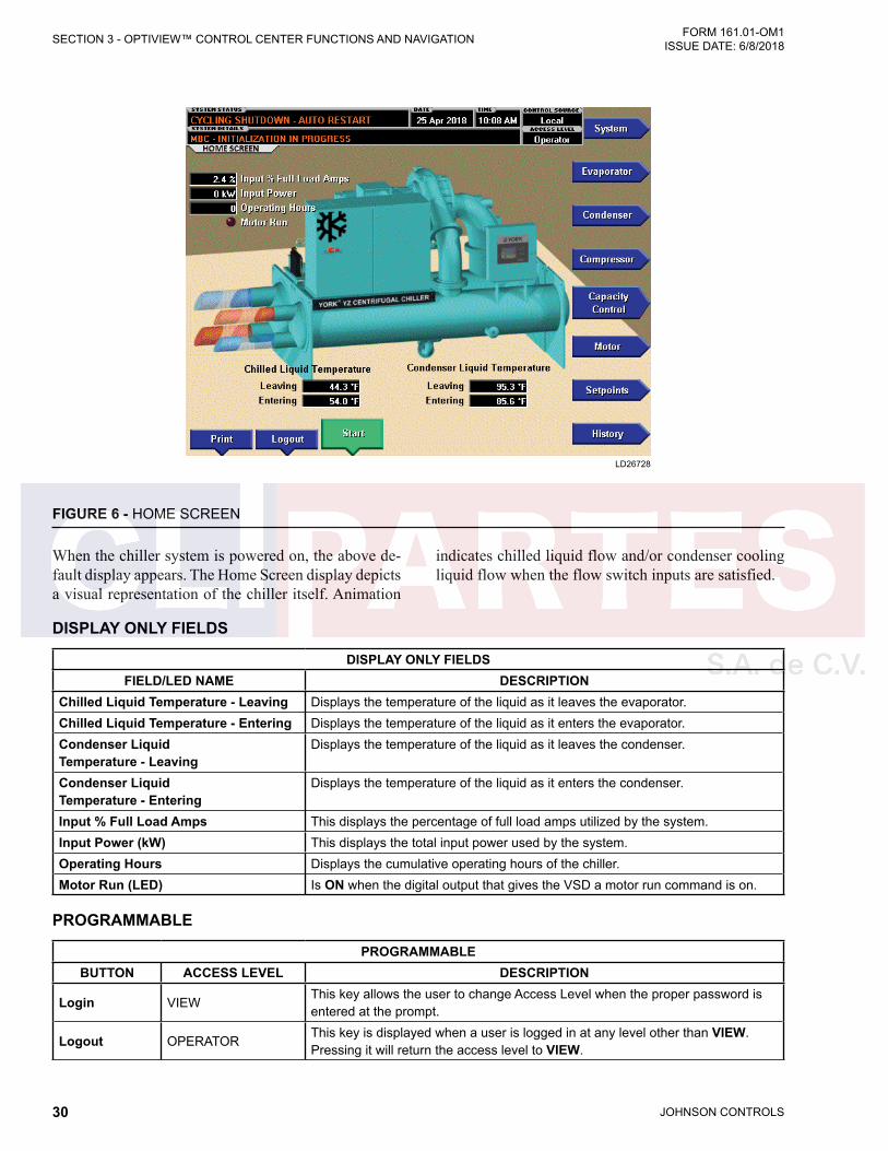
JOHNSON CONTROLS30
FORM 161.01-OM1 ISSUE DATE: 6/8/2018SECTION 3 - OPTIVIEW™ CONTROL CENTER FUNCTIONS AND NAVIGATION
FIGURE 6 - HOME SCREEN
LD26728
DISPLAY ONLY FIELDS
DISPLAY ONLY FIELDSFIELD/LED NAME DESCRIPTION
Chilled Liquid Temperature - Leaving Displays the temperature of the liquid as it leaves the evaporator.Chilled Liquid Temperature - Entering Displays the temperature of the liquid as it enters the evaporator.Condenser Liquid Temperature - Leaving
Displays the temperature of the liquid as it leaves the condenser.
Condenser Liquid Temperature - Entering
Displays the temperature of the liquid as it enters the condenser.
Input % Full Load Amps This displays the percentage of full load amps utilized by the system.Input Power (kW) This displays the total input power used by the system. Operating Hours Displays the cumulative operating hours of the chiller. Motor Run (LED) Is ON when the digital output that gives the VSD a motor run command is on.
PROGRAMMABLE
PROGRAMMABLEBUTTON ACCESS LEVEL DESCRIPTION
Login VIEWThis key allows the user to change Access Level when the proper password is entered at the prompt.
Logout OPERATORThis key is displayed when a user is logged in at any level other than VIEW. Pressing it will return the access level to VIEW.
When the chiller system is powered on, the above de-fault display appears. The Home Screen display depicts a visual representation of the chiller itself. Animation
indicates chilled liquid flow and/or condenser cooling liquid flow when the flow switch inputs are satisfied.

JOHNSON CONTROLS 31
SECTION 3 - OPTIVIEW™ CONTROL CENTER FUNCTIONS AND NAVIGATIONFORM 161.01-OM1 ISSUE DATE: 6/8/2018
3
PROGRAMMABLEBUTTON ACCESS LEVEL DESCRIPTION
Print VIEW
Use this key to generate a hard-copy report of the present system status. This provides a snapshot of the primary operating conditions at the time the key is pressed. The History page provides enhanced reporting capability. (See HISTO-RY Screen.) This option will not be present if the chiller is presently configured to print History, New Data, which continuously logs.
Clear Fault VIEW
When safety conditions have been detected, the chiller is shutdown, and the main status display of the chiller will display a message indicating the cause of the shutdown. Using this key, the fault and message can be cleared once the condition has been removed. The key only shows when the condition can be cleared. If the chiller has a standing Local or Remote run command, it will start when the key is pressed.
Warning Reset OPERATORUse of this key acknowledges a warning condition and resets the message display associated with it.
Start OPERATOR
This key is only available when the chiller does not have a local run request. Pressing this key allows selection of enter to run or cancel to abort to stopped. Enter causes the chiller to start if control source is LOCAL, or permits run if the Run/Stop source is any remote mode.
Soft Stop OPERATOR
This key is displayed whenever the chiller is running. It shows in place of the start key. Pressing this key allows selection of enter to stop or cancel to remain running. Enter causes the chiller to perform a soft shutdown and disables the remote run permissive. This key should always be used to stop the chiller un-less an emergency situation exists, in which case the Safety Stop button can be used.
NAVIGATION
NAVIGATIONBUTTON DESCRIPTION
System Jumps to the System Screen.Evaporator Navigates to the Evaporator Screen.Condenser Navigates to the Condenser Screen.
Compressor Navigates to the Compressor Screen for a detailed view of all the compressor parameters.
Capacity Control Navigates to the Capacity Control Screen for a detailed view of all the param-eters associated with capacity control
Motor Navigates to the VSD Screen to view VSD parameters. This screen allows pro-gramming of the Current Limit and the Pulldown Demand Limit values.
SetpointsThis screen provides a single location to program the most common system setpoints. It is also the gateway to many of the general system setup parameters such as Date/Time, Display Units, Scheduling, Printer Setup, etc.
History This screen provides access to a snapshot of system data at each of the last 50 shutdown conditions, and provides for trending operating parameters.
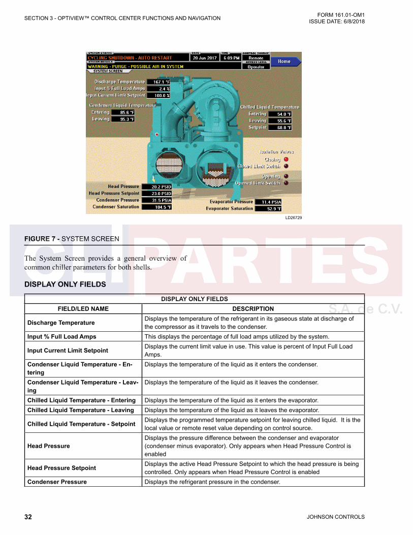
JOHNSON CONTROLS32
FORM 161.01-OM1 ISSUE DATE: 6/8/2018SECTION 3 - OPTIVIEW™ CONTROL CENTER FUNCTIONS AND NAVIGATION
FIGURE 7 - SYSTEM SCREEN
LD26729
The System Screen provides a general overview of common chiller parameters for both shells.
DISPLAY ONLY FIELDS
DISPLAY ONLY FIELDSFIELD/LED NAME DESCRIPTION
Discharge Temperature Displays the temperature of the refrigerant in its gaseous state at discharge of the compressor as it travels to the condenser.
Input % Full Load Amps This displays the percentage of full load amps utilized by the system.
Input Current Limit Setpoint Displays the current limit value in use. This value is percent of Input Full Load Amps.
Condenser Liquid Temperature - En-tering
Displays the temperature of the liquid as it enters the condenser.
Condenser Liquid Temperature - Leav-ing
Displays the temperature of the liquid as it leaves the condenser.
Chilled Liquid Temperature - Entering Displays the temperature of the liquid as it enters the evaporator.Chilled Liquid Temperature - Leaving Displays the temperature of the liquid as it leaves the evaporator.
Chilled Liquid Temperature - Setpoint Displays the programmed temperature setpoint for leaving chilled liquid. It is the local value or remote reset value depending on control source.
Head PressureDisplays the pressure difference between the condenser and evaporator (condenser minus evaporator). Only appears when Head Pressure Control is enabled
Head Pressure Setpoint Displays the active Head Pressure Setpoint to which the head pressure is being controlled. Only appears when Head Pressure Control is enabled
Condenser Pressure Displays the refrigerant pressure in the condenser.
JOHNSON CONTROLS 33
SECTION 3 - OPTIVIEW™ CONTROL CENTER FUNCTIONS AND NAVIGATIONFORM 161.01-OM1 ISSUE DATE: 6/8/2018
3
DISPLAY ONLY FIELDSFIELD/LED NAME DESCRIPTION
Condenser Saturation Temperature Displays the saturation temperature in the condenser calculated from condenser pressure.
Evaporator Pressure Displays the present refrigerant pressure in the evaporator
Evaporator Saturation Temperature Displays the present saturation temperature in the evaporator calculated from evaporator pressure.
Isolation Valves (LEDs)
Only show when optional brine isolation valve feature exists and enabled.Closing - The control is commanding the valve close output on.Closed Limit Switch - Feedback from the valve limit switch at the full closed posi-tion shows the switch made, indicating closed valve.Opening - The control is commanding the valve open output on.Opened Limit Switch - Feedback from the valve limit switch at the full open posi-tion shows the switch made, indicating open valve.
NAVIGATION
NAVIGATIONBUTTON DESCRIPTION
Home Causes an instant return to the Home Screen.
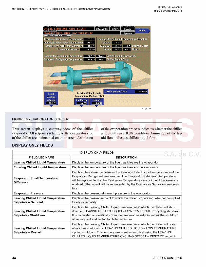
JOHNSON CONTROLS34
FORM 161.01-OM1 ISSUE DATE: 6/8/2018SECTION 3 - OPTIVIEW™ CONTROL CENTER FUNCTIONS AND NAVIGATION
FIGURE 8 - EVAPORATOR SCREEN
LD26730
DISPLAY ONLY FIELDS
DISPLAY ONLY FIELDSFIELD/LED NAME DESCRIPTION
Leaving Chilled Liquid Temperature Displays the temperature of the liquid as it leaves the evaporatorEntering Chilled Liquid Temperature Displays the temperature of the liquid as it enters the evaporator.
Evaporator Small Temperature Difference
Displays the difference between the Leaving Chilled Liquid temperature and the Evaporator Refrigerant temperature. The Evaporator Refrigerant temperature will be represented by the Refrigerant Temperature sensor input if the sensor is enabled, otherwise it will be represented by the Evaporator Saturation tempera-ture.
Evaporator Pressure Displays the present refrigerant pressure in the evaporator.Leaving Chilled Liquid Temperature Setpoints – Setpoint
Displays the present setpoint to which the chiller is operating, whether controlled locally or remotely.
Leaving Chilled Liquid Temperature Setpoints - Shutdown
Displays the Leaving Chilled Liquid Temperature at which the chiller will shut-down on LEAVING CHILLED LIQUID – LOW TEMPERATURE cycling shutdown. It is calculated automatically from the temperature setpoint minus the shutdown offset setpoint and limited to chiller minimum
Leaving Chilled Liquid Temperature Setpoints – Restart
Displays the Leaving Chilled Liquid Temperature at which the chiller will restart after it has shutdown on LEAVING CHILLED LIQUID – LOW TEMPERATURE cycling shutdown. This temperature is set as an offset using the LEAVING CHILLED LIQUID TEMPERATURE CYCLING OFFSET – RESTART setpoint.
This screen displays a cutaway view of the chiller evaporator. All setpoints relating to the evaporator side of the chiller are maintained on this screen. Animation
of the evaporation process indicates whether the chiller is presently in a RUN condition. Animation of the liq-uid flow indicates chilled liquid flow.

JOHNSON CONTROLS 35
SECTION 3 - OPTIVIEW™ CONTROL CENTER FUNCTIONS AND NAVIGATIONFORM 161.01-OM1 ISSUE DATE: 6/8/2018
3
DISPLAY ONLY FIELDSFIELD/LED NAME DESCRIPTION
Leaving Chilled Liquid Temperature Setpoints (Shutdown) – Effective Offset
Displays the present value of the leaving chilled liquid temperature shutdown offset in effect limited by the chiller minimum temperature.
Leaving Chilled Liquid Temperature Setpoints (Restart) – Offset
Displays the value set for leaving chilled liquid temperature restart offset.
Evaporator Saturation Temperature Displays the present saturation temperature in the evaporator, determined from evaporator pressure.
Evaporator Refrigerant Temperature Displays the temperature of the refrigerant in the evaporator if this option is installed and enabled.
Chilled Liquid Flow Switch (Open/Closed)
Displays whether the liquid flow switch input indicates flow is present in the evaporator.
Chilled Liquid Pump Displays the command presently sent by the control center to the Chilled Liquid Pump run contacts (RUN or STOP).
Low Evaporator Cutout The cutout value is displayed in Water mode and displayed and adjustable in Brine mode by a JCI Service Technician as appropriate for water or brine
PROGRAMMABLE
PROGRAMMABLEBUTTON ACCESS LEVEL DESCRIPTION
Local Leaving Chilled Liquid Temperature - Setpoint
Operator
This value allows the user to define the Leaving Chilled Liquid Temperature that is to be maintained by the chiller. It is programmable over the range of 36.0°F to 72.0°F (2.2 °C to 22.2 °C) (water) or 10.0°F to 72.0°F (-12.2 °C to 22.2 °C) (brine).When the chiller is running, performing capacity control, any change to the LCHLT setpoint results in a ramp from the old value to the new value at the pro-grammed LCHLT setpoint ramp rate.
Leaving Chilled Liquid Temper-ature Cycling Offset - Shutdown
Operator
This value allows the user to specify the Leaving Chilled Liquid Temperature at which the chiller will shut down on a LEAVING CHILLED LIQUID – LOW TEMPERATURE cycling shutdown. This is done by defining an offset below the Leaving Chilled Liquid Temperature setpoint. It is programmable over a range of 1°F to 70°F (-17.2 °C to 21.1 °C).
Leaving Chilled Liquid Temperature Cycling Offset - Restart
Operator
This value allows the user to specify the Leaving Chilled Liquid Temperature at which the chiller will restart after a shutdown on a LEAVING CHILLED LIQUID – LOW TEMPERATURE cycling shutdown. This is done by defining an offset above the Leaving Chilled Liquid Temperature setpoint. It is programmable over a range of 0°F to 37°F (-17.8 °C to 2.8 °C).
NAVIGATION
NAVIGATIONBUTTON DESCRIPTION
Home Causes an instant return to the Home Screen.

JOHNSON CONTROLS36
FORM 161.01-OM1 ISSUE DATE: 6/8/2018SECTION 3 - OPTIVIEW™ CONTROL CENTER FUNCTIONS AND NAVIGATION
FIGURE 9 - CONDENSER SCREEN
LD26731
DISPLAY ONLY FIELDS
DISPLAY ONLY FIELDSFIELD/LED NAME DESCRIPTION
Entering Condenser Liquid Tempera-ture
Displays the water temperature as it enters the condenser
Leaving Condenser Liquid Tempera-ture
Displays the water temperature as it leaves the condenser.
Condenser Saturation Temperature Displays the saturation temperature in the condenser.
Condenser Small Temperature Differ-ence
Displays the difference between the Condenser Refrigerant temperature and the Leaving Condenser Liquid temperature. The Condenser Refrigerant temperature will be represented by the Condenser Saturation temperature
Condenser Pressure Displays the refrigerant pressure in the condenser.
Drop Leg Refrigerant Temperature Displays the temperature of the refrigerant in the drop leg between the condens-er and evaporator shells.
Subcooling TemperatureDisplays the difference between the Condenser Refrigerant temperature and the Drop Leg Refrigerant temperature. The Condenser Refrigerant temperature will be represented by the Condenser Saturation temperature.
High Pressure Switch (Open/Closed) Displays the present position of the high pressure switch. This will indicate open when a High Pressure fault is present.
Condenser Liquid Flow Switch Indicates whether flow is present in the condenser.
Condenser Liquid Pump (Run/Stop) Displays the command presently sent by the control center to the Condenser Liquid Pump run contacts.
Condenser Refrigerant Level Displays the present position of the refrigerant level.
This screen displays a cutaway view of the chiller con-denser. All setpoints relating to the condenser side of the chiller are maintained on this screen. Animation in-
dicates condenser liquid flow. This screen also serves as a gateway to controlling the Refrigerant Level.
JOHNSON CONTROLS 37
SECTION 3 - OPTIVIEW™ CONTROL CENTER FUNCTIONS AND NAVIGATIONFORM 161.01-OM1 ISSUE DATE: 6/8/2018
3
DISPLAY ONLY FIELDSFIELD/LED NAME DESCRIPTION
Active Level Setpoint Displays the setpoint to which the refrigerant level is being controlled.
Level Control Valve Command Displays the position command to the level control valve in percent of travel with 0% full closed to 100% full open.
NAVIGATION
NAVIGATIONBUTTON DESCRIPTION
Home Causes an instant return to the Home Screen.Purge Navigates to the Purge Screen where the Operator can view the purge param-
eters and select Standard or Enhanced Purge mode of operation.Head Pressure Control Navigates to the Head Pressure Control Screen where the Operator can view
and adjust some of the Head Pressure Control parameters.
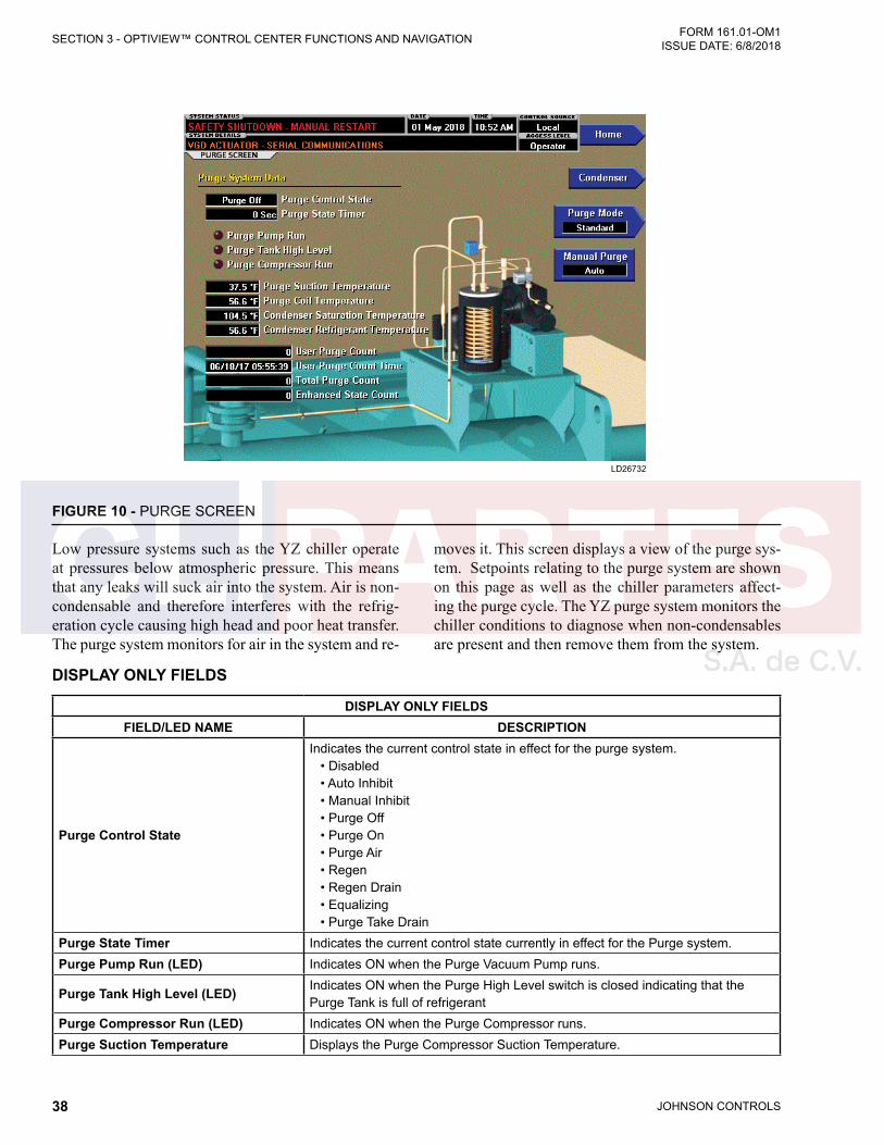
JOHNSON CONTROLS38
FORM 161.01-OM1 ISSUE DATE: 6/8/2018SECTION 3 - OPTIVIEW™ CONTROL CENTER FUNCTIONS AND NAVIGATION
FIGURE 10 - PURGE SCREEN
LD26732
DISPLAY ONLY FIELDS
DISPLAY ONLY FIELDSFIELD/LED NAME DESCRIPTION
Purge Control State
Indicates the current control state in effect for the purge system. • Disabled • Auto Inhibit • Manual Inhibit • Purge Off • Purge On • Purge Air • Regen • Regen Drain • Equalizing • Purge Take Drain
Purge State Timer Indicates the current control state currently in effect for the Purge system.Purge Pump Run (LED) Indicates ON when the Purge Vacuum Pump runs.
Purge Tank High Level (LED) Indicates ON when the Purge High Level switch is closed indicating that the Purge Tank is full of refrigerant
Purge Compressor Run (LED) Indicates ON when the Purge Compressor runs.Purge Suction Temperature Displays the Purge Compressor Suction Temperature.
Low pressure systems such as the YZ chiller operate at pressures below atmospheric pressure. This means that any leaks will suck air into the system. Air is non-condensable and therefore interferes with the refrig-eration cycle causing high head and poor heat transfer. The purge system monitors for air in the system and re-
moves it. This screen displays a view of the purge sys-tem. Setpoints relating to the purge system are shown on this page as well as the chiller parameters affect-ing the purge cycle. The YZ purge system monitors the chiller conditions to diagnose when non-condensables are present and then remove them from the system.
JOHNSON CONTROLS 39
SECTION 3 - OPTIVIEW™ CONTROL CENTER FUNCTIONS AND NAVIGATIONFORM 161.01-OM1 ISSUE DATE: 6/8/2018
3
DISPLAY ONLY FIELDSFIELD/LED NAME DESCRIPTION
Purge Coil Temperature Displays the Purge Coil temperature.
Condenser Saturation Temperature Displays the Condenser Saturation Temperature calculated from the Condenser Pressure.
Condenser Refrigerant Temperature Displays the Condenser Refrigerant temperature.
User Purge Count To aid in troubleshooting, the user may reset the Purge Count to zero and then monitor the number of purges over a period of time.
Total Purge Count Displays the date and time that the User Purge Count was reset to zero.Enhanced State Count Displays the Enhanced Purge state Count since chiller commissioning.
PROGRAMMABLE
PROGRAMMABLEBUTTON ACCESS LEVEL DESCRIPTION
Purge Mode: Standard Operator
Purge Inlet Solenoid is Open and the Purge Pump Solenoid is Closed. When the chiller runs, if the Condenser Saturation Temperature is > (Condenser Refriger-ant Temperature + Condenser Temperature Offset) [Range 0.5°F to 2.5°F (-17.5 °C to -16.4 °C), Default= 1.0°F (-17.2 °C)] the Purge Compressor will run for 1 hour. If the Purge Suction Temperature drops below -7°F (-21.7 °C) a purge cycle will be initiated.
Purge Mode: Enhanced Operator
Purge Inlet Solenoid is Open and the Purge Pump Solenoid is Closed. When the chiller runs, if the Condenser Saturation Temperature is > (Condenser Refriger-ant Temperature + Condenser Temperature Offset) [Range 0.5°F to 2.5°F (-17.5 °C to -16.4 °C), Default= 1.0°F (-17.2 °C)] the Purge Compressor will run for 1 hour. If the Purge Suction Temperature drops below -7°F (-21.7 °C) a purge cycle will be initiated. If the Purge Suction Temperature does not drop below -7°F (-21.7 °C), the Purge Compressor will turn off for 4 hours. After the 4 hour wait the Purge Compressor will be run for another hour. If the Purge Suction Temp drops below -7°F (-21.7 °C) a purge cycle will be initiated. If it does not drop then the Purge Compressor will again be shut off for a 4 hour wait. If no purges are needed after 3 four hour purge cycles, the Purge Compressor will stay off for 24 hours. If no purges occur after 7 twenty-four hour purge cycles then the Purge Time Interval will increase to 1 week and remain there indefinitely.If at any time during the enhanced mode of operation the Purge Suction Tem-perature drops below -7°F (-21.7 °C) a purge cycle will be initiated and the purge cycle time will revert back to the four hour off time.
NAVIGATION
NAVIGATIONBUTTON DESCRIPTION
Home Returns user to HOME ScreenCondenser Returns user to CONDENSER Screen
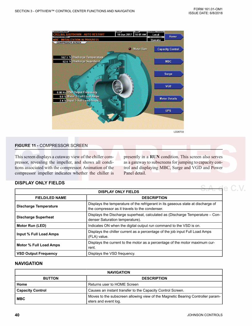
JOHNSON CONTROLS40
FORM 161.01-OM1 ISSUE DATE: 6/8/2018SECTION 3 - OPTIVIEW™ CONTROL CENTER FUNCTIONS AND NAVIGATION
FIGURE 11 - COMPRESSOR SCREEN
LD26733
DISPLAY ONLY FIELDS
DISPLAY ONLY FIELDSFIELD/LED NAME DESCRIPTION
Discharge Temperature Displays the temperature of the refrigerant in its gaseous state at discharge of the compressor as it travels to the condenser.
Discharge Superheat Displays the Discharge superheat, calculated as (Discharge Temperature – Con-denser Saturation temperature).
Motor Run (LED) Indicates ON when the digital output run command to the VSD is on.
Input % Full Load Amps Displays the chiller current as a percentage of the job input Full Load Amps (FLA) value.
Motor % Full Load Amps Displays the current to the motor as a percentage of the motor maximum cur-rent.
VSD Output Frequency Displays the VSD frequency.
NAVIGATION
NAVIGATIONBUTTON DESCRIPTION
Home Returns user to HOME ScreenCapacity Control Causes an instant transfer to the Capacity Control Screen.
MBC Moves to the subscreen allowing view of the Magnetic Bearing Controller param-eters and event log.
This screen displays a cutaway view of the chiller com-pressor, revealing the impeller, and shows all condi-tions associated with the compressor. Animation of the compressor impeller indicates whether the chiller is
presently in a RUN condition. This screen also serves as a gateway to subscreens for jumping to capacity con-trol and displaying MBC, Surge and VGD and Power Panel detail.
JOHNSON CONTROLS 41
SECTION 3 - OPTIVIEW™ CONTROL CENTER FUNCTIONS AND NAVIGATIONFORM 161.01-OM1 ISSUE DATE: 6/8/2018
3
NAVIGATIONBUTTON DESCRIPTION
Surge Moves to the subscreen that allows viewing and programming of the Surge Protection feature.
VGD Moves to the subscreen that allows viewing and calibrating the Variable Geom-etry Diffuser feature. Programming requires an access level of SERVICE.
Motor Details Moves to the screen showing motor operating details.Power Panel Moves to the subscreen that allows viewing power panel status and parameters.
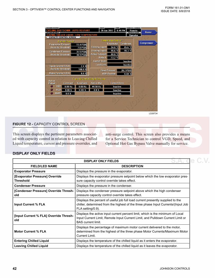
JOHNSON CONTROLS42
FORM 161.01-OM1 ISSUE DATE: 6/8/2018SECTION 3 - OPTIVIEW™ CONTROL CENTER FUNCTIONS AND NAVIGATION
FIGURE 12 - CAPACITY CONTROL SCREEN
LD26734
DISPLAY ONLY FIELDS
DISPLAY ONLY FIELDSFIELD/LED NAME DESCRIPTION
Evaporator Pressure Displays the pressure in the evaporator.[Evaporator Pressure] Override Threshold
Displays the evaporator pressure setpoint below which the low evaporator pres-sure capacity control override takes effect.
Condenser Pressure Displays the pressure in the condenser.[Condenser Pressure] Override Thresh-old
Displays the condenser pressure setpoint above which the high condenser pressure capacity control override takes effect.
Input Current % FLADisplays the percent of useful job full load current presently supplied to the chiller, determined from the highest of the three phase Input Currents/(Input Job FLA setting/0.9).
[Input Current % FLA] Override Thresh-old
Displays the active input current percent limit, which is the minimum of Local Input Current Limit, Remote Input Current Limit, and Pulldown Current Limit or BAS current limit.
Motor Current % FLADisplays the percentage of maximum motor current delivered to the motor, determined from the highest of the three phase Motor Currents/Maximum Motor Current Limit.
Entering Chilled Liquid Displays the temperature of the chilled liquid as it enters the evaporator.Leaving Chilled Liquid Displays the temperature of the chilled liquid as it leaves the evaporator.
This screen displays the pertinent parameters associat-ed with capacity control in relation to Leaving Chilled Liquid temperature, current and pressure overrides, and
anti-surge control. This screen also provides a means for a Service Technician to control VGD, Speed, and Optional Hot Gas Bypass Valve manually for service.

JOHNSON CONTROLS 43
SECTION 3 - OPTIVIEW™ CONTROL CENTER FUNCTIONS AND NAVIGATIONFORM 161.01-OM1 ISSUE DATE: 6/8/2018
3
DISPLAY ONLY FIELDSFIELD/LED NAME DESCRIPTION
Active LCHLT Setpoint
Displays the active temperature setpoint to which the chiller is set to control liq-uid leaving the evaporator. The Active Setpoint is a target to the Local, Remote or BAS (ISN) LCHLT programmed setpoint, depending on the control source selected. When the chiller is not running, the Active Setpoint is set to Entering Chilled Liquid Temperature - LCHLT Setpoint Start Offset When the VSD starts, the Active LCHLT Setpoint is ramped to the programmed LCHLT Setpoint at the programmable LCHLT Setpoint Ramp Rate. When the chiller is running, performing capacity control, any change to the programmed LCHLT setpoint results in a ramp from the old Active Setpoint value to the new LCHLT setpoint value at the programmed LCHLT Setpoint Ramp Rate.
Delta T Displays the difference between the temperature of the chilled liquid leaving the evaporator and the Leaving Chilled Liquid Active Setpoint.
Control State
Displays the present source controlling the command to the capacity control devices, based on conditions as follows: • Inactive – Capacity Control is not active • Temperature Control – Capacity Control is active with no overrides acting • Input Current – Input Current Override is in control • Motor Current – Motor Current Override is in control • Condenser Pressure – Condenser Pressure Override is in control • Evaporator Pressure – Evaporator Pressure Override is in control • Low LCHLT – LCHLT low temperature Override is in control
Load Limit
Displays if any load limiting control is acting on the temperature control output to the capacity control devices. The field indicates the following: • Inactive – Capacity Control is not active • None – No limit is in effect • Input Current • Motor Current • Condenser Pressure • Evaporator Pressure
Head Pressure Displays the difference between condenser refrigerant pressure and evaporator refrigerant pressure.
Entering Condenser Liquid Tempera-ture
Displays the temperature of the condenser liquid entering the condenser.
VGD Position Displays the Position of the VGD actuator.
Capacity Control Output Devices
Displays the following for each of the devices that is available: VSD (Variable Speed Drive), VGD (Variable Geometry Diffuser) or HGBP (Hot Gas Bypass Valve) • Active Output (LED): Indicates which device is currently selected by the
control for manipulation. • Command: Displays the output command from the control to the device in
Hertz to the VSD or in percent of full open to the VGD or HGBP valve. • Feedback: Displays the present speed feedback from the VSD or present
position feedback from the VGD. • Control Mode: Displays whether the device is under Automatic or Manual
control. • Active Min: Displays the prevailing minimum value to which the control to the
device is limited, based upon surge controls or operating limits. • Control State: Displays whether the device is under Automatic or Manual
control.
JOHNSON CONTROLS44
FORM 161.01-OM1 ISSUE DATE: 6/8/2018SECTION 3 - OPTIVIEW™ CONTROL CENTER FUNCTIONS AND NAVIGATION
NAVIGATION
NAVIGATIONBUTTON DESCRIPTION
Home Causes and instant return to the Home Screen.Compressor Causes an instant navigation to the Compressor Screen.VSD Causes an instant navigation to the VSD Screen.
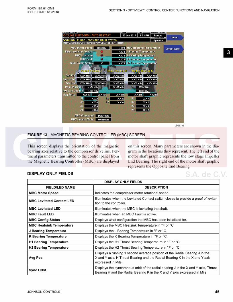
JOHNSON CONTROLS 45
SECTION 3 - OPTIVIEW™ CONTROL CENTER FUNCTIONS AND NAVIGATIONFORM 161.01-OM1 ISSUE DATE: 6/8/2018
3
FIGURE 13 - MAGNETIC BEARING CONTROLLER (MBC) SCREEN
LD26735
DISPLAY ONLY FIELDS
DISPLAY ONLY FIELDSFIELD/LED NAME DESCRIPTION
MBC Motor Speed Indicates the compressor motor rotational speed.
MBC Levitated Contact LED Illuminates when the Levitated Contact switch closes to provide a proof of levita-tion to the controller.
MBC Levitated LED Illuminates when the MBC is levitating the shaft.MBC Fault LED Illuminates when an MBC Fault is active.MBC Config Status Displays what configuration the MBC has been initialized for.MBC Heatsink Temperature Displays the MBC Heatsink Temperature in °F or °C.J Bearing Temperature Displays the J Bearing Temperature in °F or °C.K Bearing Temperature Displays the K Bearing Temperature in °F or °C.H1 Bearing Temperature Displays the H1 Thrust Bearing Temperature in °F or °C.H2 Bearing Temperature Displays the H2 Thrust Bearing Temperature in °F or °C.
Avg PosDisplays a running 1 second average position of the Radial Bearing J in the X and Y axis. H Thrust Bearing and the Radial Bearing K in the X and Y axis expressed in Mils.
Sync Orbit Displays the synchronous orbit of the radial bearing J in the X and Y axis, Thrust Bearing H and the Radial Bearing K in the X and Y axis expressed in Mils
This screen displays the orientation of the magnetic bearing axes relative to the compressor driveline. Per-tinent parameters transmitted to the control panel from the Magnetic Bearing Controller (MBC) are displayed
on this screen. Many parameters are shown in the dia-gram in the locations they represent. The left end of the motor shaft graphic represents the low stage Impeller End Bearing. The right end of the motor shaft graphic represents the Opposite End Bearing.

JOHNSON CONTROLS46
FORM 161.01-OM1 ISSUE DATE: 6/8/2018SECTION 3 - OPTIVIEW™ CONTROL CENTER FUNCTIONS AND NAVIGATION
DISPLAY ONLY FIELDSFIELD/LED NAME DESCRIPTION
Std DevDisplays the Standard Deviation of the Radial Bearing J in the X and Y axis, Thrust Bearing H and the Radial Bearing K in the X and Y axis expressed in Mils.
Peak Vibration Displays the Peak Vibration of the Radial Bearing J, Thrust Bearing H and the Radial Bearing K expressed in Mils.
Avg Gap ChangeDisplays the Average Gap Change of the Radial Bearing J and the Radial Bear-ing K expressed in Mils.
Avg ForceDisplays a running 1 second Average Force of the Radial Bearing J in the X and Y axis, Thrust Bearing H and the Radial Bearing K in the X and Y axis. Expressed in lbs or Nm.
J1, J2, J3, J4 (Current) Displays the four magnetizing currents for the impeller end bearing expressed in Amps.
H1, H2 (Current) Displays the two magnetizing currents for the thrust bearing expressed in Amps.
K1, K2, K3, K4 (Current) Displays the four magnetizing currents for the drive end bearing expressed in Amps.
MBC Command Displays the OptiView state command to the MBC. (Delevitate, Levitate or Cali-brate).
MBC Control Mode Indicates the MBC Control Mode. (Delevitated, Levitated, Calibrating J, Calibrat-ing K or Calibrating H).
NAVIGATION
NAVIGATIONBUTTON DESCRIPTION
Home Causes immediate return to the Home Screen.Compressor Causes immediate transfer to the Compressor Screen.
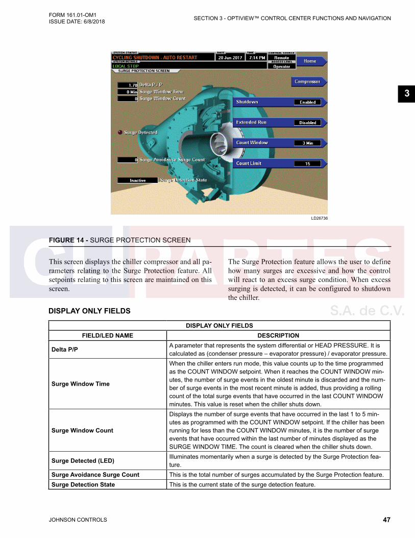
JOHNSON CONTROLS 47
SECTION 3 - OPTIVIEW™ CONTROL CENTER FUNCTIONS AND NAVIGATIONFORM 161.01-OM1 ISSUE DATE: 6/8/2018
3
FIGURE 14 - SURGE PROTECTION SCREEN
LD26736
DISPLAY ONLY FIELDS
DISPLAY ONLY FIELDSFIELD/LED NAME DESCRIPTION
Delta P/P A parameter that represents the system differential or HEAD PRESSURE. It is calculated as (condenser pressure – evaporator pressure) / evaporator pressure.
Surge Window Time
When the chiller enters run mode, this value counts up to the time programmed as the COUNT WINDOW setpoint. When it reaches the COUNT WINDOW min-utes, the number of surge events in the oldest minute is discarded and the num-ber of surge events in the most recent minute is added, thus providing a rolling count of the total surge events that have occurred in the last COUNT WINDOW minutes. This value is reset when the chiller shuts down.
Surge Window Count
Displays the number of surge events that have occurred in the last 1 to 5 min-utes as programmed with the COUNT WINDOW setpoint. If the chiller has been running for less than the COUNT WINDOW minutes, it is the number of surge events that have occurred within the last number of minutes displayed as the SURGE WINDOW TIME. The count is cleared when the chiller shuts down.
Surge Detected (LED) Illuminates momentarily when a surge is detected by the Surge Protection fea-ture.
Surge Avoidance Surge Count This is the total number of surges accumulated by the Surge Protection feature.Surge Detection State This is the current state of the surge detection feature.
This screen displays the chiller compressor and all pa-rameters relating to the Surge Protection feature. All setpoints relating to this screen are maintained on this screen.
The Surge Protection feature allows the user to define how many surges are excessive and how the control will react to an excess surge condition. When excess surging is detected, it can be configured to shutdown the chiller.

JOHNSON CONTROLS48
FORM 161.01-OM1 ISSUE DATE: 6/8/2018SECTION 3 - OPTIVIEW™ CONTROL CENTER FUNCTIONS AND NAVIGATION
PROGRAMMABLE
PROGRAMMABLEBUTTON ACCESS LEVEL DESCRIPTION
Shutdown (Enabled/ Disabled)
OperatorAllows the user to select whether the chiller will shutdown or continue to run when an Excess Surge situation has been detected.
Extended Run (Enabled/ Disabled)
OperatorAllows the user to select whether the chiller will shut-down or continue to run when an Excess Surge situation has been detected.
Count Window Operator
Allows the user to define the period of time (1 to 5 minutes; default 5; default 3 in which the number of surge events (SURGE WINDOW COUNT) are compared to the maximum allowed (COUNT LIMIT), for the purpose of detecting an excess surge situation
Count Limit Operator
Allows the user to define the maximum number of surge events (4 to 20; default 4; default 15 that can occur within a defined period of time before an Excess Surge situation is detected. If the SURGE WINDOW COUNT exceeds the COUNT LIMIT, an Excess Surge situation has occurred.When an Excess Surge situation is detected, and the SHUTDOWN setpoint is Enabled, the chiller will perform a safety shutdown and display SURGE PRO-TECTION – EXCESS SURGE.
NAVIGATION
NAVIGATIONBUTTON DESCRIPTION
Home Causes an instant return to the Home Screen.Condenser Causes an instant return to the Compressor Screen.
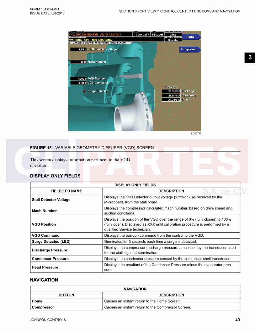
JOHNSON CONTROLS 49
SECTION 3 - OPTIVIEW™ CONTROL CENTER FUNCTIONS AND NAVIGATIONFORM 161.01-OM1 ISSUE DATE: 6/8/2018
3
FIGURE 15 - VARIABLE GEOMETRY DIFFUSER (VGD) SCREEN
LD26737
This screen displays information pertinent to the VGD operation.
DISPLAY ONLY FIELDS
DISPLAY ONLY FIELDSFIELD/LED NAME DESCRIPTION
Stall Detector Voltage Displays the Stall Detector output voltage (x.xxVdc), as received by the Microboard, from the stall board.
Mach Number Displays the compressor calculated mach number, based on drive speed and suction conditions.
VGD PositionDisplays the position of the VGD over the range of 0% (fully closed) to 100% (fully open). Displayed as XXX until calibration procedure is performed by a qualified Service technician.
VGD Command Displays the position command from the control to the VGD.Surge Detected (LED) Illuminates for 5 seconds each time a surge is detected.
Discharge Pressure Displays the compressor discharge pressure as sensed by the transducer used for the stall signal determination.
Condenser Pressure Displays the condenser pressure sensed by the condenser shell transducer.
Head Pressure Displays the resultant of the Condenser Pressure minus the evaporator pres-sure.
NAVIGATION
NAVIGATIONBUTTON DESCRIPTION
Home Causes an instant return to the Home Screen.Compressor Causes an instant return to the Compressor Screen.
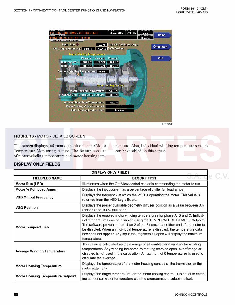
JOHNSON CONTROLS50
FORM 161.01-OM1 ISSUE DATE: 6/8/2018SECTION 3 - OPTIVIEW™ CONTROL CENTER FUNCTIONS AND NAVIGATION
FIGURE 16 - MOTOR DETAILS SCREEN
LD26738
DISPLAY ONLY FIELDS
DISPLAY ONLY FIELDSFIELD/LED NAME DESCRIPTION
Motor Run (LED) Illuminates when the OptiView control center is commanding the motor to run.Motor % Full Load Amps Displays the input current as a percentage of chiller full load amps.
VSD Output Frequency Displays the frequency at which the VSD is operating the motor. This value is returned from the VSD Logic Board.
VGD Position Displays the present variable geometry diffuser position as a value between 0% (closed) and 100% (full open).
Motor Temperatures
Displays the enabled motor winding temperatures for phase A, B and C. Individ-ual temperatures can be disabled using the TEMPERATURE DISABLE Setpoint. The software prevents more than 2 of the 3 sensors at either end of the motor to be disabled. When an individual temperature is disabled, the temperature data box does not appear. Any input that registers as open will display the minimum temperature.
Average Winding Temperature
This value is calculated as the average of all enabled and valid motor winding temperatures. Any winding temperature that registers as open, out of range or disabled is not used in the calculation. A maximum of 6 temperatures is used to calculate the average.
Motor Housing Temperature Displays the temperature of the motor housing sensed at the thermistor on the motor externally.
Motor Housing Temperature Setpoint Displays the target temperature for the motor cooling control. It is equal to enter-ing condenser water temperature plus the programmable setpoint offset.
This screen displays information pertinent to the Motor Temperature Monitoring feature. The feature consists of motor winding temperature and motor housing tem-
perature. Also, individual winding temperature sensors can be disabled on this screen

JOHNSON CONTROLS 51
SECTION 3 - OPTIVIEW™ CONTROL CENTER FUNCTIONS AND NAVIGATIONFORM 161.01-OM1 ISSUE DATE: 6/8/2018
3
DISPLAY ONLY FIELDSFIELD/LED NAME DESCRIPTION
Ambient Dew Point Temperature When the optional Ambient Dew Point Temperature sensor is Enabled, its read-ing is displayed here.
Motor Cooling Valve Command Output to the motor cooling valve in percent from 0% (closed) to 100% Opened)Motor Cooling Control State Displays whether the motor cooling valve is in Auto, Manual or Inactive control.
NAVIGATION
NAVIGATIONBUTTON DESCRIPTION
Home Returns user to HOME ScreenVSD Returns to the VSD Screen.
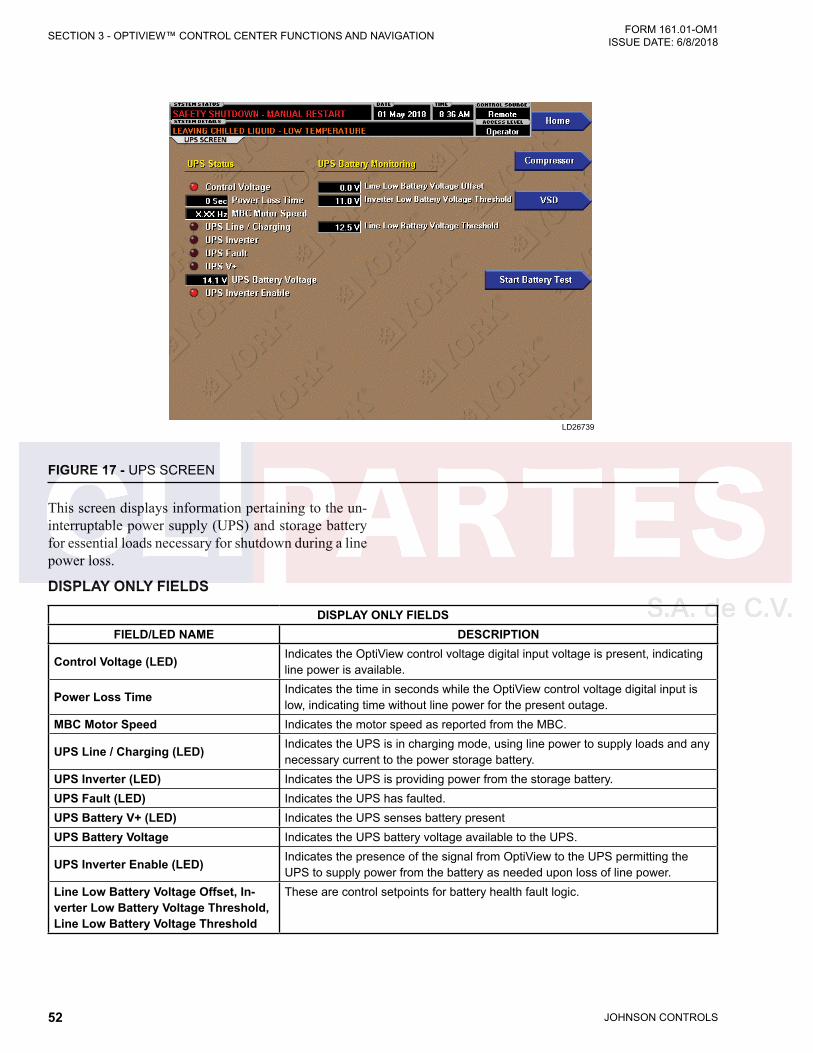
JOHNSON CONTROLS52
FORM 161.01-OM1 ISSUE DATE: 6/8/2018SECTION 3 - OPTIVIEW™ CONTROL CENTER FUNCTIONS AND NAVIGATION
FIGURE 17 - UPS SCREEN
LD26739
DISPLAY ONLY FIELDS
DISPLAY ONLY FIELDSFIELD/LED NAME DESCRIPTION
Control Voltage (LED) Indicates the OptiView control voltage digital input voltage is present, indicating line power is available.
Power Loss Time Indicates the time in seconds while the OptiView control voltage digital input is low, indicating time without line power for the present outage.
MBC Motor Speed Indicates the motor speed as reported from the MBC.
UPS Line / Charging (LED) Indicates the UPS is in charging mode, using line power to supply loads and any necessary current to the power storage battery.
UPS Inverter (LED) Indicates the UPS is providing power from the storage battery.UPS Fault (LED) Indicates the UPS has faulted.UPS Battery V+ (LED) Indicates the UPS senses battery presentUPS Battery Voltage Indicates the UPS battery voltage available to the UPS.
UPS Inverter Enable (LED) Indicates the presence of the signal from OptiView to the UPS permitting the UPS to supply power from the battery as needed upon loss of line power.
Line Low Battery Voltage Offset, In-verter Low Battery Voltage Threshold, Line Low Battery Voltage Threshold
These are control setpoints for battery health fault logic.
This screen displays information pertaining to the un-interruptable power supply (UPS) and storage battery for essential loads necessary for shutdown during a line power loss.
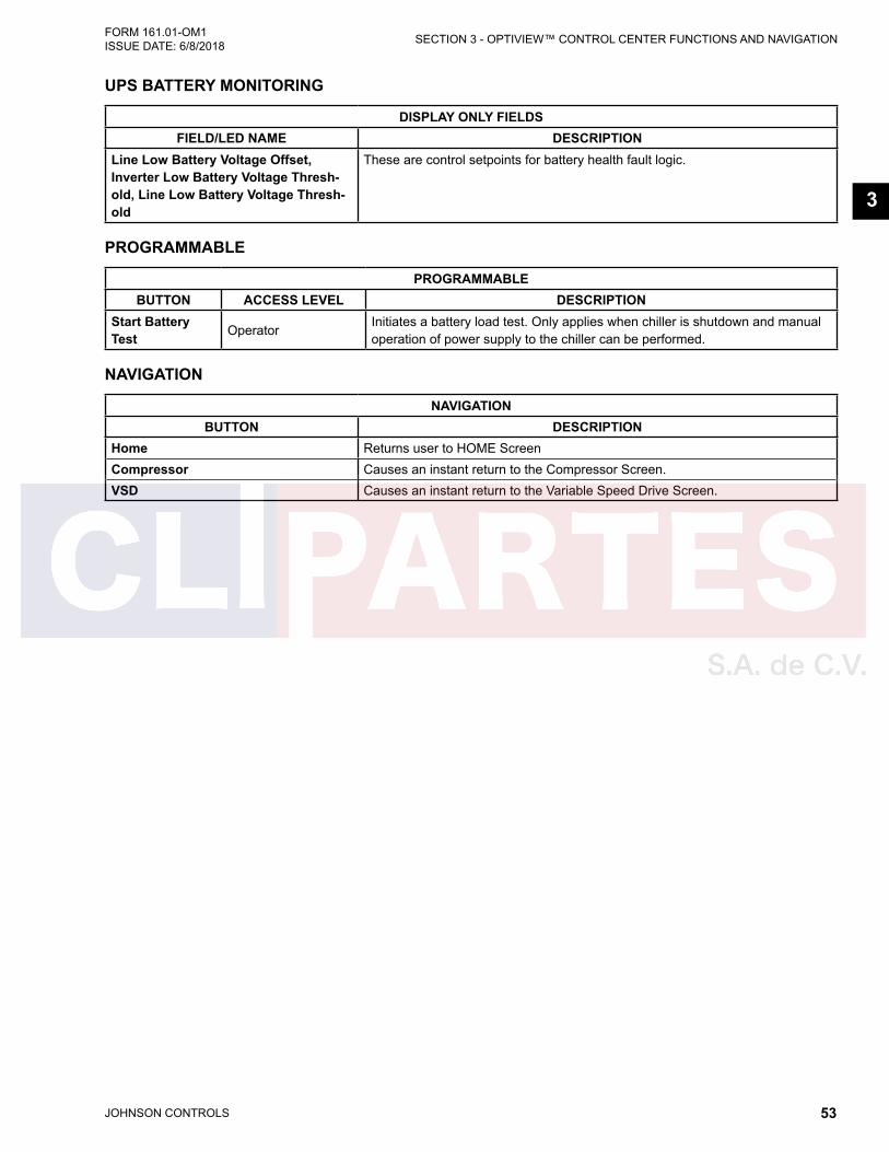
JOHNSON CONTROLS 53
SECTION 3 - OPTIVIEW™ CONTROL CENTER FUNCTIONS AND NAVIGATIONFORM 161.01-OM1 ISSUE DATE: 6/8/2018
3
UPS BATTERY MONITORING
DISPLAY ONLY FIELDSFIELD/LED NAME DESCRIPTION
Line Low Battery Voltage Offset, Inverter Low Battery Voltage Thresh-old, Line Low Battery Voltage Thresh-old
These are control setpoints for battery health fault logic.
PROGRAMMABLE
PROGRAMMABLEBUTTON ACCESS LEVEL DESCRIPTION
Start Battery Test Operator
Initiates a battery load test. Only applies when chiller is shutdown and manual operation of power supply to the chiller can be performed.
NAVIGATION
NAVIGATIONBUTTON DESCRIPTION
Home Returns user to HOME ScreenCompressor Causes an instant return to the Compressor Screen.VSD Causes an instant return to the Variable Speed Drive Screen.
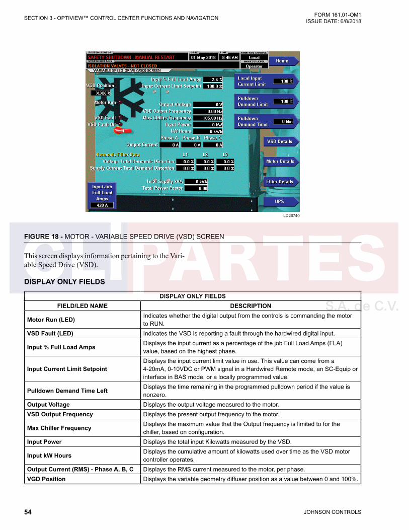
JOHNSON CONTROLS54
FORM 161.01-OM1 ISSUE DATE: 6/8/2018SECTION 3 - OPTIVIEW™ CONTROL CENTER FUNCTIONS AND NAVIGATION
FIGURE 18 - MOTOR - VARIABLE SPEED DRIVE (VSD) SCREEN
LD26740
This screen displays information pertaining to the Vari-able Speed Drive (VSD).
DISPLAY ONLY FIELDS
DISPLAY ONLY FIELDSFIELD/LED NAME DESCRIPTION
Motor Run (LED) Indicates whether the digital output from the controls is commanding the motor to RUN.
VSD Fault (LED) Indicates the VSD is reporting a fault through the hardwired digital input.
Input % Full Load Amps Displays the input current as a percentage of the job Full Load Amps (FLA) value, based on the highest phase.
Input Current Limit SetpointDisplays the input current limit value in use. This value can come from a 4-20mA, 0-10VDC or PWM signal in a Hardwired Remote mode, an SC-Equip or interface in BAS mode, or a locally programmed value.
Pulldown Demand Time Left Displays the time remaining in the programmed pulldown period if the value is nonzero.
Output Voltage Displays the output voltage measured to the motor.VSD Output Frequency Displays the present output frequency to the motor.
Max Chiller Frequency Displays the maximum value that the Output frequency is limited to for the chiller, based on configuration.
Input Power Displays the total input Kilowatts measured by the VSD.
Input kW Hours Displays the cumulative amount of kilowatts used over time as the VSD motor controller operates.
Output Current (RMS) - Phase A, B, C Displays the RMS current measured to the motor, per phase.VGD Position Displays the variable geometry diffuser position as a value between 0 and 100%.
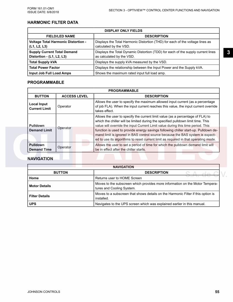
JOHNSON CONTROLS 55
SECTION 3 - OPTIVIEW™ CONTROL CENTER FUNCTIONS AND NAVIGATIONFORM 161.01-OM1 ISSUE DATE: 6/8/2018
3
HARMONIC FILTER DATA
DISPLAY ONLY FIELDSFIELD/LED NAME DESCRIPTION
Voltage Total Harmonic Distortion - (L1, L2, L3)
Displays the Total Harmonic Distortion (THD) for each of the voltage lines as calculated by the VSD.
Supply Current Total Demand Distortion - (L1, L2, L3)
Displays the Total Dynamic Distortion (TDD) for each of the supply current lines as calculated by the VSD.
Total Supply kVA Displays the supply kVA measured by the VSD.Total Power Factor Displays the relationship between the Input Power and the Supply kVA.Input Job Full Load Amps Shows the maximum rated input full load amp.
PROGRAMMABLE
PROGRAMMABLEBUTTON ACCESS LEVEL DESCRIPTION
Local Input Current Limit Operator
Allows the user to specify the maximum allowed input current (as a percentage of job FLA). When the input current reaches this value, the input current override takes effect.
Pulldown Demand Limit Operator
Allows the user to specify the current limit value (as a percentage of FLA) to which the chiller will be limited during the specified pulldown limit time. This value will override the input Current Limit value during this time period. This function is used to provide energy savings following chiller start-up. Pulldown de-mand limit is ignored in BAS control source because the BAS system is expect-ed to use its algorithms to reset current limit as required in that operating mode.
Pulldown Demand Time Operator
Allows the user to set a period of time for which the pulldown demand limit will be in effect after the chiller starts.
NAVIGATION
NAVIGATIONBUTTON DESCRIPTION
Home Returns user to HOME Screen
Motor Details Moves to the subscreen which provides more information on the Motor Tempera-tures and Cooling System.
Filter Details Moves to a subscreen that shows details on the Harmonic Filter if this option is installed.
UPS Navigates to the UPS screen which was explained earlier in this manual.

JOHNSON CONTROLS56
FORM 161.01-OM1 ISSUE DATE: 6/8/2018SECTION 3 - OPTIVIEW™ CONTROL CENTER FUNCTIONS AND NAVIGATION
FIGURE 19 - VARIABLE SPEED DRIVE (VSD) DETAILS SCREEN
LD26741
This screen displays more detailed parameters associ-ated with the Variable Speed Drive. This screen also provides a means for a Service Technician to access setpoints for maintenance or service.
DISPLAY ONLY FIELDS
DISPLAY ONLY FIELDSFIELD/LED NAME DESCRIPTION
Motor Run (LED) Indicates the digital output from the controls is commanding the motor to RUN.Input % Full Load Amps Displays the current draw as a percentage of the unit Full Load Amps.Motor % Full Load Amps Displays the current draw as a percentage of the motor Full Load Amps.Input Current Displays the Input Current to the VSD.Motor Full Load Amps Displays the rated motor FLA.VSD Model Displays the VSD model as reported by the VSD.
Water Pump Output (LED) Indicates the relay controlling the VSD water pump and fans output is ener-gized.
Precharge Relay Output (LED) Indicates the VSD DC bus has been pre-charged.Trigger SCR Output (LED) Indicates the Trigger SCRs are energized.DC Bus Voltage Displays the DC Bus voltage.DC Inverter Link Current Displays the current draw of the Inverter from the DC Link.
Internal Ambient Temperature Displays the ambient temperature inside the VSD cabinet as reported by the VSD.
Converter Heatsink Temperature Displays the highest VSD input rectifier baseplate temperature.
Baseplate Temperature Displays VSD output inverter baseplate temperatures. When there are multiple power modules per phase, the highest temperature per phase is displayed.

JOHNSON CONTROLS 57
SECTION 3 - OPTIVIEW™ CONTROL CENTER FUNCTIONS AND NAVIGATIONFORM 161.01-OM1 ISSUE DATE: 6/8/2018
3
NAVIGATION
NAVIGATIONBUTTON DESCRIPTION
Home Causes an instant return to the Home screen.VSD Causes an instant return to the VSD screen
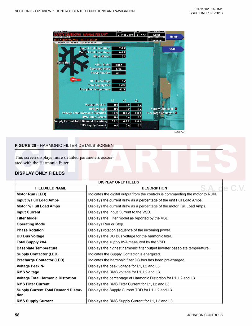
JOHNSON CONTROLS58
FORM 161.01-OM1 ISSUE DATE: 6/8/2018SECTION 3 - OPTIVIEW™ CONTROL CENTER FUNCTIONS AND NAVIGATION
FIGURE 20 - HARMONIC FILTER DETAILS SCREEN
LD26727
This screen displays more detailed parameters associ-ated with the Harmonic Filter.
DISPLAY ONLY FIELDS
DISPLAY ONLY FIELDSFIELD/LED NAME DESCRIPTION
Motor Run (LED) Indicates the digital output from the controls is commanding the motor to RUN.Input % Full Load Amps Displays the current draw as a percentage of the unit Full Load Amps.Motor % Full Load Amps Displays the current draw as a percentage of the motor Full Load Amps.Input Current Displays the Input Current to the VSD.Filter Model Displays the Filter model as reported by the VSD.Operating Mode Displays Run or Stop.Phase Rotation Displays rotation sequence of the incoming power.DC Bus Voltage Displays the DC Bus voltage for the harmonic filter.Total Supply kVA Displays the supply kVA measured by the VSD.Baseplate Temperature Displays the highest harmonic filter output inverter baseplate temperature.Supply Contactor (LED) Indicates the Supply Contactor is energized.Precharge Contactor (LED) Indicates the harmonic filter DC bus has been pre-charged.Voltage Peak N- Displays the peak voltage for L1, L2 and L3.RMS Voltage Displays the RMS voltage for L1, L2 and L3.Voltage Total Harmonic Distortion Displays the percentage of Harmonic Distortion for L1, L2 and L3.RMS Filter Current Displays the RMS Filter Current for L1, L2 and L3.Supply Current Total Demand Distor-tion
Displays the Supply Current TDD for L1, L2 and L3.
RMS Supply Current Displays the RMS Supply Current for L1, L2 and L3.

JOHNSON CONTROLS 59
SECTION 3 - OPTIVIEW™ CONTROL CENTER FUNCTIONS AND NAVIGATIONFORM 161.01-OM1 ISSUE DATE: 6/8/2018
3
NAVIGATION
NAVIGATIONBUTTON DESCRIPTION
Home Causes an instant return to the Home screen.VSD Causes an instant return to the VSD screen
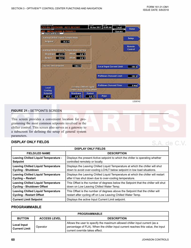
JOHNSON CONTROLS60
FORM 161.01-OM1 ISSUE DATE: 6/8/2018SECTION 3 - OPTIVIEW™ CONTROL CENTER FUNCTIONS AND NAVIGATION
FIGURE 21 - SETPOINTS SCREEN
LD26742
DISPLAY ONLY FIELDS
DISPLAY ONLY FIELDSFIELD/LED NAME DESCRIPTION
Leaving Chilled Liquid Temperature - Setpoint
Displays the present Active setpoint to which the chiller is operating whether controlled remotely or locally.
Leaving Chilled Liquid Temperature Cycling - Shutdown
Displays the Leaving Chilled Liquid Temperature at which the chiller will shut down to avoid over-cooling LCHLT below setpoint in low load situations.
Leaving Chilled Liquid Temperature Cycling – Restart
Displays the Leaving Chilled Liquid Temperature at which the chiller will restart after it has shut down due to over-cooling temperature.
Leaving Chilled Liquid Temperature Cycling - Shutdown Offset
This Offset is the number of degrees below the Setpoint that the chiller will shut down on Low Leaving Chilled Water Temp.
Leaving Chilled Liquid Temperature Cycling - Restart Offset
This Offset is the number of degrees above the Setpoint that the chiller will restart after cycling off on Low Leaving Chilled Water Temp.
Current Limit Setpoint Displays the active Input Current Limit setpoint.
PROGRAMMABLE
PROGRAMMABLEBUTTON ACCESS LEVEL DESCRIPTION
Local Input Current Limit Operator
Allows the user to specify the maximum allowed chiller input current (as a percentage of FLA). When the chiller input current reaches this value, the input current override takes effect.
This screen provides a convenient location for pro-gramming the most common setpoints involved in the chiller control. This screen also serves as a gateway to a subscreen for defining the setup of general system parameters.
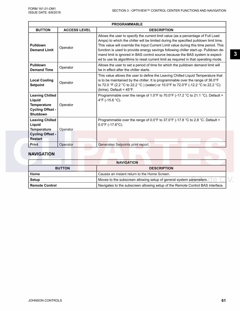
JOHNSON CONTROLS 61
SECTION 3 - OPTIVIEW™ CONTROL CENTER FUNCTIONS AND NAVIGATIONFORM 161.01-OM1 ISSUE DATE: 6/8/2018
3
PROGRAMMABLEBUTTON ACCESS LEVEL DESCRIPTION
Pulldown Demand Limit Operator
Allows the user to specify the current limit value (as a percentage of Full Load Amps) to which the chiller will be limited during the specified pulldown limit time. This value will override the Input Current Limit value during this time period. This function is used to provide energy savings following chiller start-up. Pulldown de-mand limit is ignored in BAS control source because the BAS system is expect-ed to use its algorithms to reset current limit as required in that operating mode.
Pulldown Demand Time Operator
Allows the user to set a period of time for which the pulldown demand limit will be in effect after the chiller starts.
Local Cooling Setpoint Operator
This value allows the user to define the Leaving Chilled Liquid Temperature that is to be maintained by the chiller. It is programmable over the range of 36.0°F to 72.0 °F (2.2 °C to 22.2 °C ) (water) or 10.0°F to 72.0°F (-12.2 °C to 22.2 °C) (brine). Default = 45°F.
Leaving Chilled Liquid Temperature Cycling Offset - Shutdown
Operator
Programmable over the range of 1.0°F to 70.0°F (-17.2 °C to 21.1 °C). Default = 4°F (-15.6 °C).
Leaving Chilled Liquid Temperature Cycling Offset - Restart
Operator
Programmable over the range of 0.0°F to 37.0°F (-17.8 °C to 2.8 °C. Default = 0.0°F (-17.8°C).
Print Operator Generates Setpoints print report.
NAVIGATION
NAVIGATIONBUTTON DESCRIPTION
Home Causes an instant return to the Home Screen.Setup Moves to the subscreen allowing setup of general system parameters.Remote Control Navigates to the subscreen allowing setup of the Remote Control BAS interface.
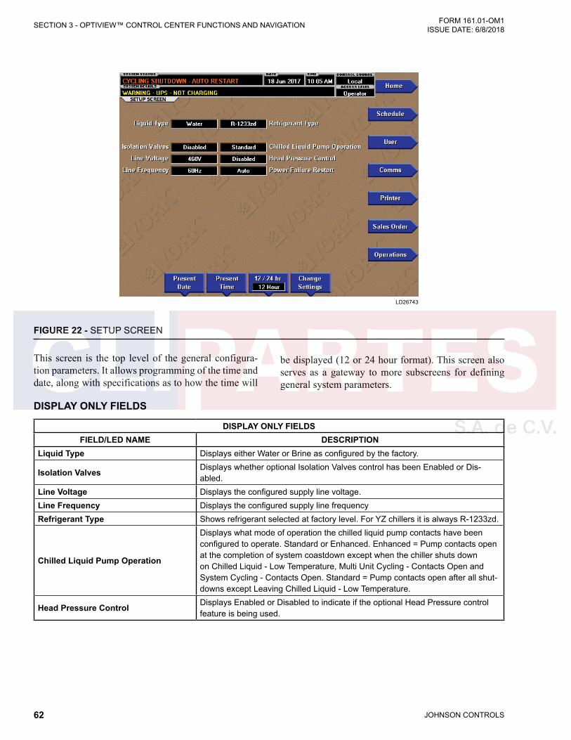
JOHNSON CONTROLS62
FORM 161.01-OM1 ISSUE DATE: 6/8/2018SECTION 3 - OPTIVIEW™ CONTROL CENTER FUNCTIONS AND NAVIGATION
FIGURE 22 - SETUP SCREEN
LD26743
DISPLAY ONLY FIELDS
DISPLAY ONLY FIELDSFIELD/LED NAME DESCRIPTION
Liquid Type Displays either Water or Brine as configured by the factory.
Isolation Valves Displays whether optional Isolation Valves control has been Enabled or Dis-abled.
Line Voltage Displays the configured supply line voltage.Line Frequency Displays the configured supply line frequencyRefrigerant Type Shows refrigerant selected at factory level. For YZ chillers it is always R-1233zd.
Chilled Liquid Pump Operation
Displays what mode of operation the chilled liquid pump contacts have been configured to operate. Standard or Enhanced. Enhanced = Pump contacts open at the completion of system coastdown except when the chiller shuts down on Chilled Liquid - Low Temperature, Multi Unit Cycling - Contacts Open and System Cycling - Contacts Open. Standard = Pump contacts open after all shut-downs except Leaving Chilled Liquid - Low Temperature.
Head Pressure Control Displays Enabled or Disabled to indicate if the optional Head Pressure control feature is being used.
This screen is the top level of the general configura-tion parameters. It allows programming of the time and date, along with specifications as to how the time will
be displayed (12 or 24 hour format). This screen also serves as a gateway to more subscreens for defining general system parameters.
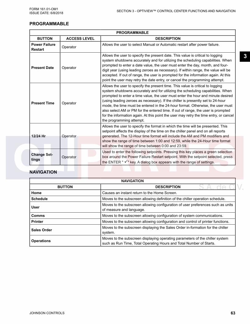
JOHNSON CONTROLS 63
SECTION 3 - OPTIVIEW™ CONTROL CENTER FUNCTIONS AND NAVIGATIONFORM 161.01-OM1 ISSUE DATE: 6/8/2018
3
PROGRAMMABLE
PROGRAMMABLEBUTTON ACCESS LEVEL DESCRIPTION
Power Failure Restart Operator
Allows the user to select Manual or Automatic restart after power failure.
Present Date Operator
Allows the user to specify the present date. This value is critical to logging system shutdowns accurately and for utilizing the scheduling capabilities. When prompted to enter a date value, the user must enter the day, month, and four-digit year (using leading zeroes as necessary). If within range, the value will be accepted. If out of range, the user is prompted for the information again. At this point the user may retry the date entry, or cancel the programming attempt.
Present Time Operator
Allows the user to specify the present time. This value is critical to logging system shutdowns accurately and for utilizing the scheduling capabilities. When prompted to enter a time value, the user must enter the hour and minute desired (using leading zeroes as necessary). If the chiller is presently set to 24-hour mode, the time must be entered in the 24-hour format. Otherwise, the user must also select AM or PM for the entered time. If out of range, the user is prompted for the information again. At this point the user may retry the time entry, or cancel the programming attempt.
12/24 Hr Operator
Allows the user to specify the format in which the time will be presented. This setpoint affects the display of the time on the chiller panel and on all reports generated. The 12-Hour time format will include the AM and PM modifiers and show the range of time between 1:00 and 12:59, while the 24-Hour time format will show the range of time between 0:00 and 23:59.
Change Set-tings Operator
Used to enter the following setpoints. Pressing this key places a green selection box around the Power Failure Restart setpoint. With the setpoint selected, press the ENTER " " key. A dialog box appears with the range of settings.
NAVIGATION
NAVIGATIONBUTTON DESCRIPTION
Home Causes an instant return to the Home Screen.Schedule Moves to the subscreen allowing definition of the chiller operation schedule.
User Moves to the subscreen allowing configuration of user preferences such as units of measure and language.
Comms Moves to the subscreen allowing configuration of system communications.Printer Moves to the subscreen allowing configuration and control of printer functions.
Sales Order Moves to the subscreen displaying the Sales Order in-formation for the chiller system.
Operations Moves to the subscreen displaying operating parameters of the chiller system such as Run Time, Total Operating Hours and Total Number of Starts.

JOHNSON CONTROLS64
FORM 161.01-OM1 ISSUE DATE: 6/8/2018SECTION 3 - OPTIVIEW™ CONTROL CENTER FUNCTIONS AND NAVIGATION
FIGURE 23 - SCHEDULE SCREEN
LD26744
The schedule screen contains more programmable val-ues than a normal display screen. As such, each pro-grammable value is not linked to a specific button. In-stead the Select key is used to enable the cursor arrows which are used to highlight the day and the start or stop time the user wishes to modify. At this point the user may press the " " (Check) key to program the Start / Stop times for that day.
In order for the Start / Stop combination to be uti-lized, each Start time must have a corresponding Stop time which occurs later in the day. The presently pro-grammed schedule for a given day can be cancelled by setting both the Start time and Stop time to 12:00 AM. If the Start time equals the Stop time (with any time other than 12:00 AM), the chiller is OFF for that day. If the user desires the chiller to operate continuously
through several days, the Stop time of Day 1 can be set to 11:59 PM and the Start time of Day 2 can be set to 12:00 AM. The chiller will not stop but continue to operate until the stop of Day 2.
The user has the ability to define a standard set of Start / Stop times which are utilized every week. The user may then specify exception Start / Stop combinations for any day of the week up to 6 weeks in advance. At the end of each week the schedule for the next week is created by combining the standard week definition and the next defined exception week. The schedule is then updated as each of the exception weeks “shifts down”, leaving a new, blank exception week in the 6th week slot.
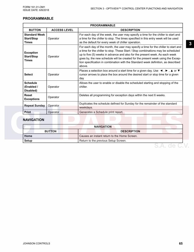
JOHNSON CONTROLS 65
SECTION 3 - OPTIVIEW™ CONTROL CENTER FUNCTIONS AND NAVIGATIONFORM 161.01-OM1 ISSUE DATE: 6/8/2018
3
PROGRAMMABLE
PROGRAMMABLEBUTTON ACCESS LEVEL DESCRIPTION
Standard Week Start/Stop Times
OperatorFor each day of the week, the user may specify a time for the chiller to start and a time for the chiller to stop. The times specified in this entry week will be used as the default for every week of chiller operation.
Exception Start/Stop Times
Operator
For each day of the month, the user may specify a time for the chiller to start and a time for the chiller to stop. These Start / Stop combinations may be scheduled up to five (5) weeks in advance and also for the present week. As each week goes by, the new schedule will be created for the present week using the Excep-tion specification in combination with the Standard week definition, as described above.
Select OperatorPlaces a selection box around a start time for a given day. Use ◄ , ► , ▲ or ▼ cursor arrows to place the box around the desired start or stop time for a given day
Schedule (Enabled / Disabled)
OperatorAllows the user to enable or disable the scheduled starting and stopping of the chiller.
Reset Exceptions Operator
Deletes all programming for exception days within the next 6 weeks.
Repeat Sunday OperatorDuplicates the schedule defined for Sunday for the remainder of the standard weekdays.
Print Operator Generates a Schedule print report.
NAVIGATION
NAVIGATIONBUTTON DESCRIPTION
Home Causes an instant return to the Home Screen.Setup Return to the previous Setup Screen.
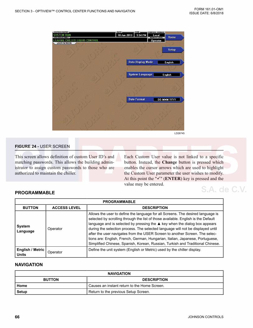
JOHNSON CONTROLS66
FORM 161.01-OM1 ISSUE DATE: 6/8/2018SECTION 3 - OPTIVIEW™ CONTROL CENTER FUNCTIONS AND NAVIGATION
FIGURE 24 - USER SCREEN
LD26745
PROGRAMMABLE
PROGRAMMABLEBUTTON ACCESS LEVEL DESCRIPTION
System Language Operator
Allows the user to define the language for all Screens. The desired language is selected by scrolling through the list of those available. English is the Default language and is selected by pressing the ▲ key when the dialog box appears during the selection process. The selected language will not be displayed until after the user navigates from the USER Screen to another Screen. The selec-tions are: English, French, German, Hungarian, Italian, Japanese, Portuguese, Simplified Chinese, Spanish, Korean, Russian, Turkish and Traditional Chinese.
English / Metric Units Operator
Define the unit system (English or Metric) used by the chiller display.
NAVIGATION
NAVIGATIONBUTTON DESCRIPTION
Home Causes an instant return to the Home Screen.Setup Return to the previous Setup Screen.
This screen allows definition of custom User ID’s and matching passwords. This allows the building admin-istrator to assign custom passwords to those who are authorized to maintain the chiller.
Each Custom User value is not linked to a specific button. Instead, the Change button is pressed which enables the cursor arrows which are used to highlight the Custom User parameter the user wishes to modify. At this point the "" (ENTER) key is pressed and the value may be entered.
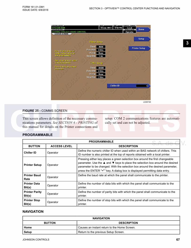
JOHNSON CONTROLS 67
SECTION 3 - OPTIVIEW™ CONTROL CENTER FUNCTIONS AND NAVIGATIONFORM 161.01-OM1 ISSUE DATE: 6/8/2018
3
FIGURE 25 - COMMS SCREEN
LD26746
PROGRAMMABLE
PROGRAMMABLEBUTTON ACCESS LEVEL DESCRIPTION
Chiller ID OperatorDefine the numeric chiller ID when used within an BAS network of chillers. This ID number is also printed at the top of reports obtained with a local printer.
Printer Setup Operator
Pressing either key places a green selection box around the first changeable parameter. Use the ▲ and ▼ keys to place the selection box around the desired parameter to be changed. With the selection box around the desired parameter, press the ENTER "" key. A dialog box is displayed permitting data entry.
Printer Baud Rate Operator
Define the baud rate at which the panel shall communicate to the printer.
Printer Data Bit(s) Operator
Define the number of data bits with which the panel shall communicate to the printer.
Printer Parity Bit(s) Operator
Define the number of parity bits with which the panel shall communicate to the printer.
Printer Stop Bit(s) Operator
Define the number of stop bits with which the panel shall communicate to the printer.
NAVIGATION
NAVIGATIONBUTTON DESCRIPTION
Home Causes an instant return to the Home Screen.Setup Return to the previous Setup Screen.
This screen allows definition of the necessary commu-nications parameters. See SECTION 6 - PRINTING of this manual for details on the Printer connections and
setup. COM 2 communications features are automati-cally set and can not be adjusted.
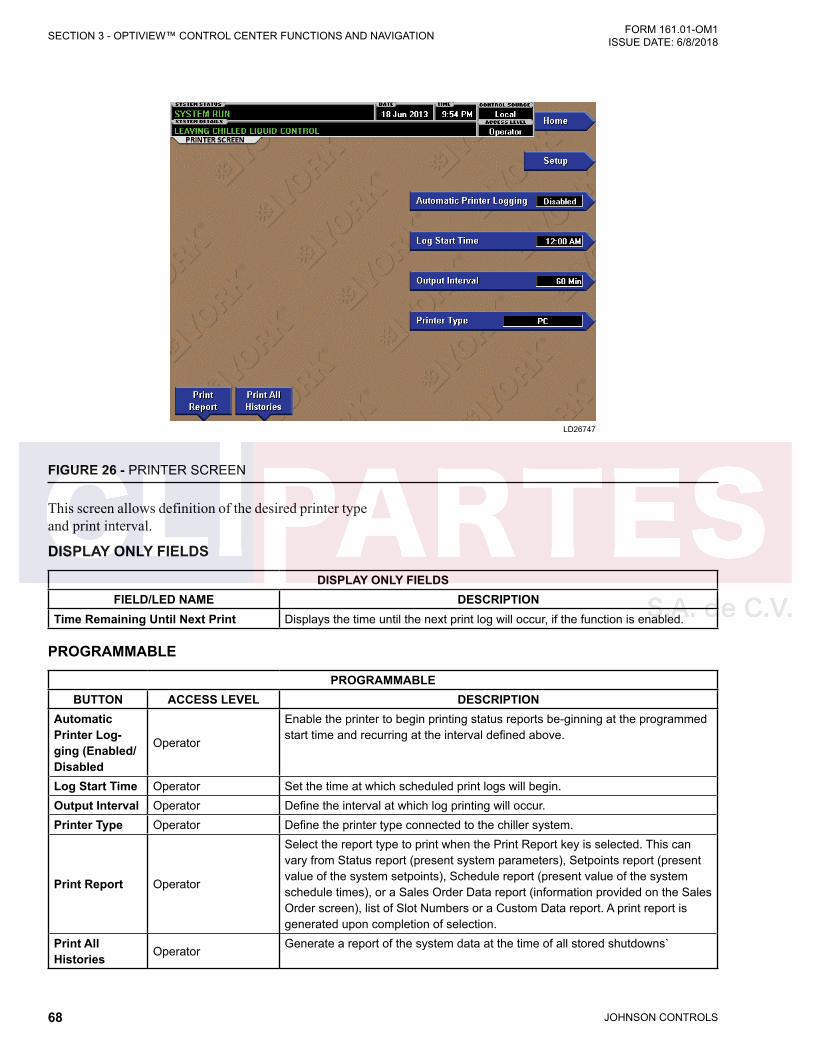
JOHNSON CONTROLS68
FORM 161.01-OM1 ISSUE DATE: 6/8/2018SECTION 3 - OPTIVIEW™ CONTROL CENTER FUNCTIONS AND NAVIGATION
FIGURE 26 - PRINTER SCREEN
LD26747
This screen allows definition of the desired printer type and print interval.
DISPLAY ONLY FIELDS
DISPLAY ONLY FIELDSFIELD/LED NAME DESCRIPTION
Time Remaining Until Next Print Displays the time until the next print log will occur, if the function is enabled.
PROGRAMMABLE
PROGRAMMABLEBUTTON ACCESS LEVEL DESCRIPTION
Automatic Printer Log-ging (Enabled/ Disabled
Operator
Enable the printer to begin printing status reports be-ginning at the programmed start time and recurring at the interval defined above.
Log Start Time Operator Set the time at which scheduled print logs will begin.Output Interval Operator Define the interval at which log printing will occur.Printer Type Operator Define the printer type connected to the chiller system.
Print Report Operator
Select the report type to print when the Print Report key is selected. This can vary from Status report (present system parameters), Setpoints report (present value of the system setpoints), Schedule report (present value of the system schedule times), or a Sales Order Data report (information provided on the Sales Order screen), list of Slot Numbers or a Custom Data report. A print report is generated upon completion of selection.
Print All Histories Operator
Generate a report of the system data at the time of all stored shutdowns`

JOHNSON CONTROLS 69
SECTION 3 - OPTIVIEW™ CONTROL CENTER FUNCTIONS AND NAVIGATIONFORM 161.01-OM1 ISSUE DATE: 6/8/2018
3
NAVIGATION
NAVIGATIONBUTTON DESCRIPTION
Home Causes an instant return to the Home Screen.Setup Return to the previous Setup Screen.

JOHNSON CONTROLS70
FORM 161.01-OM1 ISSUE DATE: 6/8/2018SECTION 3 - OPTIVIEW™ CONTROL CENTER FUNCTIONS AND NAVIGATION
FIGURE 27 - SALES ORDER SCREEN
LD26748
DISPLAY ONLY FIELDS
DISPLAY ONLY FIELDSFIELD/LED NAME DESCRIPTION
Commissioning Date Define the date at which the chiller was commissioned.Job Name and Location Factory defined job name and location the chiller is destined for.Model Number Factory defined model number of the chiller system.YORK Order Number Factory defined order number under which the chiller was sold.Panel Serial Number Factory defined serial number for the control panel.Chiller Serial Number Factory defined serial number for the chiller system.Evaporator and Condenser Passes Factory defined number of passes.Evaporator and Condenser Water Box Press
Factory defined Water Box Pressure rating.
Evaporator and Condenser Pressure Drop
Factory defined Pressure drop across the shell.
Evap and Cond Nozzle Arrangement In Factory defined inlet nozzle arrangements.Evap and Cond Leaving Liquid Factory defined design Leaving Liquid Temperature.Evap and Cond Entering Liquid Factory defined design Entering Liquid Temperature.Evap and Cond Flow Factory defined design Flow RatesEvap and Cond Tube Code Factory defined Tube Codes.Motor Code Factory defined Motor Code.
This screen displays the sales order parameters. The Commissioning date is entered by the YORK/Johnson Controls Service Technician at the time of chiller com-
missioning. These values should never be changed or entered by anyone other than a qualified Service Tech-nician. The remainder of the values are entered at the YORK Factory during the manufacturing of the chiller.
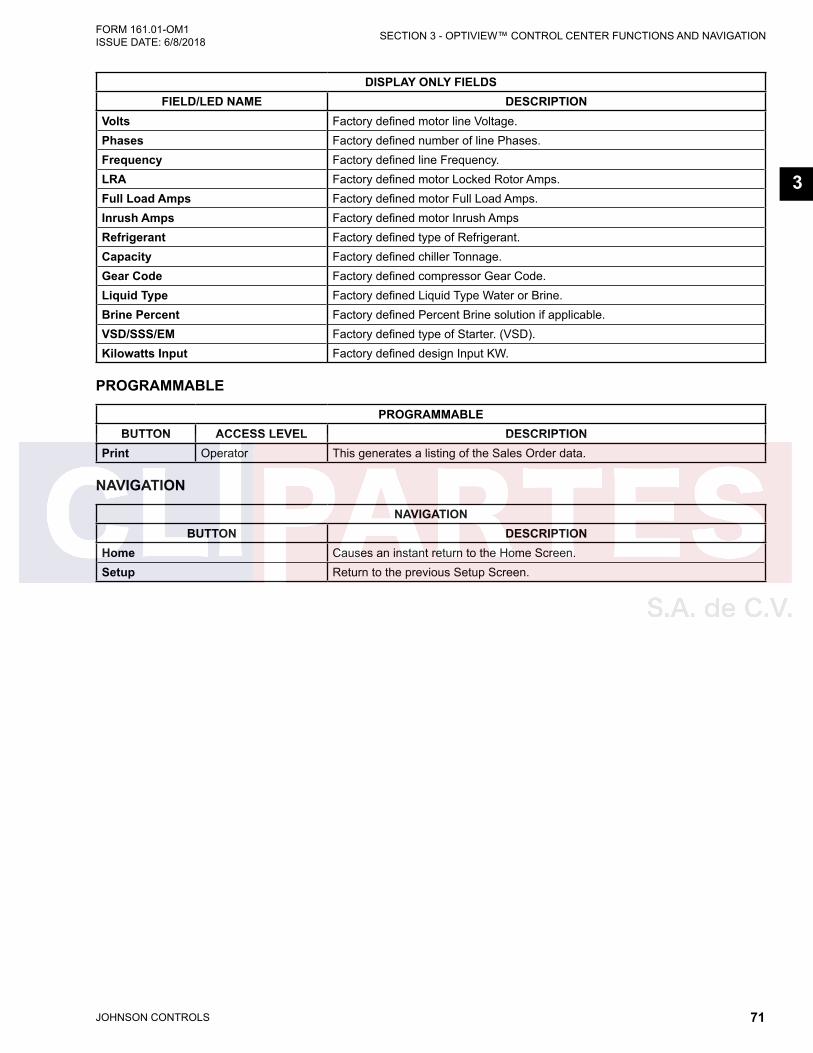
JOHNSON CONTROLS 71
SECTION 3 - OPTIVIEW™ CONTROL CENTER FUNCTIONS AND NAVIGATIONFORM 161.01-OM1 ISSUE DATE: 6/8/2018
3
DISPLAY ONLY FIELDSFIELD/LED NAME DESCRIPTION
Volts Factory defined motor line Voltage.Phases Factory defined number of line Phases.Frequency Factory defined line Frequency.LRA Factory defined motor Locked Rotor Amps.Full Load Amps Factory defined motor Full Load Amps.Inrush Amps Factory defined motor Inrush AmpsRefrigerant Factory defined type of Refrigerant.Capacity Factory defined chiller Tonnage.Gear Code Factory defined compressor Gear Code.Liquid Type Factory defined Liquid Type Water or Brine.Brine Percent Factory defined Percent Brine solution if applicable.VSD/SSS/EM Factory defined type of Starter. (VSD).Kilowatts Input Factory defined design Input KW.
PROGRAMMABLE
PROGRAMMABLEBUTTON ACCESS LEVEL DESCRIPTION
Print Operator This generates a listing of the Sales Order data.
NAVIGATION
NAVIGATIONBUTTON DESCRIPTION
Home Causes an instant return to the Home Screen.Setup Return to the previous Setup Screen.
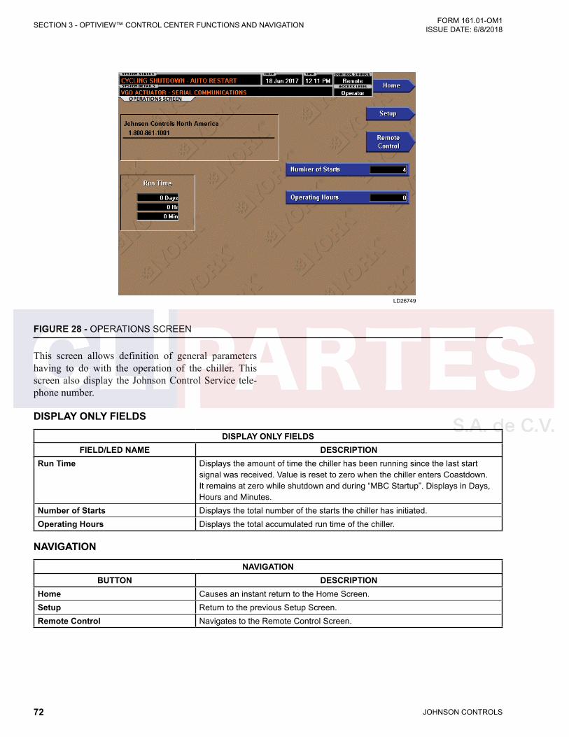
JOHNSON CONTROLS72
FORM 161.01-OM1 ISSUE DATE: 6/8/2018SECTION 3 - OPTIVIEW™ CONTROL CENTER FUNCTIONS AND NAVIGATION
FIGURE 28 - OPERATIONS SCREEN
LD26749
This screen allows definition of general parameters having to do with the operation of the chiller. This screen also display the Johnson Control Service tele-phone number.
DISPLAY ONLY FIELDS
DISPLAY ONLY FIELDSFIELD/LED NAME DESCRIPTION
Run Time Displays the amount of time the chiller has been running since the last start signal was received. Value is reset to zero when the chiller enters Coastdown. It remains at zero while shutdown and during “MBC Startup”. Displays in Days, Hours and Minutes.
Number of Starts Displays the total number of the starts the chiller has initiated. Operating Hours Displays the total accumulated run time of the chiller.
NAVIGATION
NAVIGATIONBUTTON DESCRIPTION
Home Causes an instant return to the Home Screen.Setup Return to the previous Setup Screen.Remote Control Navigates to the Remote Control Screen.

JOHNSON CONTROLS 73
SECTION 3 - OPTIVIEW™ CONTROL CENTER FUNCTIONS AND NAVIGATIONFORM 161.01-OM1 ISSUE DATE: 6/8/2018
3
FIGURE 29 - REMOTE CONTROL SCREEN
LD26750
PROGRAMMABLE
PROGRAMMABLEBUTTON ACCESS LEVEL DESCRIPTION
Select Run/Stop Operator
Upon pressing the Select Run/Stop button the user may then choose the source for Run/Stop control of the chiller. Local, BAS or Hardwire. Default = Local
Select Cooling OperatorUpon pressing the Select Cooling button the user may then choose the source of the chiller Cooling Setpoint. Local, BAS, 0-10V, 4-20mA, PWM. Default = Local.
Select Current Limit Operator
Upon pressing the Select Current Limit button the user may then choose the source for Current Limit Setpoint of the chiller. Local, BAS, 0-10V, 4-20mA or PWM. Default = Local..
NAVIGATION
NAVIGATIONBUTTON DESCRIPTION
Home Causes an instant return to the Home Screen.Setup Return to the previous Setup Screen.Operations Returns to the Operations Screen.
This screen allows the user to independently select the method of control for Run/Stop, Cooling Setpoint and Current Limit Setpoint. This gives complete flexibil-ity for the control interface. Refer to YZ Field Control Modification 161.01-PW2 for more information on BAS interface specifics.
• In Local mode the chiller will control to the Local Setpoint.
• In BAS mode a Building Automation System may communicate the Setpoint via an optional SC-EQ communication card.
• In Hardwire, 0-10V, 4-20mA or PWM, the BAS interface uses hardwired control signals.

JOHNSON CONTROLS74
FORM 161.01-OM1 ISSUE DATE: 6/8/2018SECTION 3 - OPTIVIEW™ CONTROL CENTER FUNCTIONS AND NAVIGATION
FIGURE 30 - HISTORY SCREEN
LD26751
DISPLAY ONLY FIELDS
DISPLAY ONLY FIELDSFIELD/LED NAME DESCRIPTION
Last Normal Shutdown This window displays the date and time and the description of the last normal shutdown. A normal shutdown is defined as: • Local (Soft Stop Button) • Remote (Hardwire or BAS)
Last Fault While Running This window displays the date and time and the description of the last safety or cycling shutdown while the system was running.
Last Fifty Faults This window displays a chronological listing (most recent first) of the date and time and the description of the last 50 safety or cycling shutdowns that occur while the system is running or stopped.
PROGRAMMABLE
PROGRAMMABLEBUTTON ACCESS LEVEL DESCRIPTION
Select Fault OperatorAllows the user to select which type of faults to display. Normal, Running or #1 through #10 of the presently displayed faults.
Page Up Operator Scrolls up 10 faults on the display.
This screen allows the user to browse through the faults. In order to get a more thorough reporting of the system conditions at the time of the recorded shutdown, move to the History Details subscreen.
The user may use the Select Fault button to select the history to view. At this point the View Details button
is used to jump to a subscreen containing stored chiller parameters values at the time of the shutdown. Addi-tionally, the Print History button can be used to gen-erate a hard-copy report of the parameter values at the time of the shutdown.
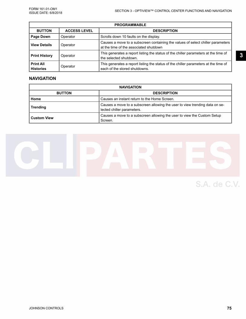
JOHNSON CONTROLS 75
SECTION 3 - OPTIVIEW™ CONTROL CENTER FUNCTIONS AND NAVIGATIONFORM 161.01-OM1 ISSUE DATE: 6/8/2018
3
PROGRAMMABLEBUTTON ACCESS LEVEL DESCRIPTION
Page Down Operator Scrolls down 10 faults on the display.
View Details OperatorCauses a move to a subscreen containing the values of select chiller parameters at the time of the associated shutdown
Print History OperatorThis generates a report listing the status of the chiller parameters at the time of the selected shutdown.
Print All Histories Operator
This generates a report listing the status of the chiller parameters at the time of each of the stored shutdowns.
NAVIGATION
NAVIGATIONBUTTON DESCRIPTION
Home Causes an instant return to the Home Screen.
Trending Causes a move to a subscreen allowing the user to view trending data on se-lected chiller parameters.
Custom View Causes a move to a subscreen allowing the user to view the Custom Setup Screen.
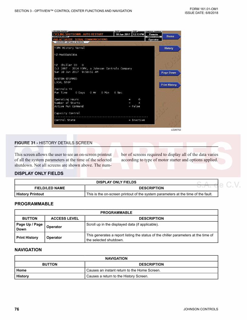
JOHNSON CONTROLS76
FORM 161.01-OM1 ISSUE DATE: 6/8/2018SECTION 3 - OPTIVIEW™ CONTROL CENTER FUNCTIONS AND NAVIGATION
FIGURE 31 - HISTORY DETAILS SCREEN
LD26752
DISPLAY ONLY FIELDS
DISPLAY ONLY FIELDSFIELD/LED NAME DESCRIPTION
History Printout This is the on-screen printout of the system parameters at the time of the fault.
PROGRAMMABLE
PROGRAMMABLEBUTTON ACCESS LEVEL DESCRIPTION
Page Up / Page Down Operator Scroll up in the displayed data (if applicable).
Print History Operator This generates a report listing the status of the chiller parameters at the time of the selected shutdown.
NAVIGATION
NAVIGATIONBUTTON DESCRIPTION
Home Causes an instant return to the Home Screen.History Causes a return to the History Screen.
This screen allows the user to see an on-screen printout of all the system parameters at the time of the selected shutdown. Not all screens are shown above. The num-
ber of screens required to display all of the data varies according to type of motor starter and options applied.

JOHNSON CONTROLS 77
SECTION 3 - OPTIVIEW™ CONTROL CENTER FUNCTIONS AND NAVIGATIONFORM 161.01-OM1 ISSUE DATE: 6/8/2018
3
FIGURE 32 - CUSTOM SCREEN
LD26753
PROGRAMMABLE
PROGRAMMABLEBUTTON ACCESS LEVEL DESCRIPTION
Print Operator This generates a listing of the parameters displayed on this screen.
NAVIGATION
NAVIGATIONBUTTON ACCESS LEVEL DESCRIPTION
Home View Causes an instant return to the Home Screen.History View Causes an instant return to the History Screen.
Setup Operator Causes a jump to the subscreen where the parameters to be displayed on the custom screen are selected.
This screen allows up to 10 Service Technician select-ed parameters to be displayed. These parameters are selected from the slot list on the Custom View Setup Screen. This allows the Service Technician to display
parameters pertinent to a particular problem during troubleshooting. At completion of the service call, the display can be cleared or the parameters can be left there for monitoring by operations personnel.
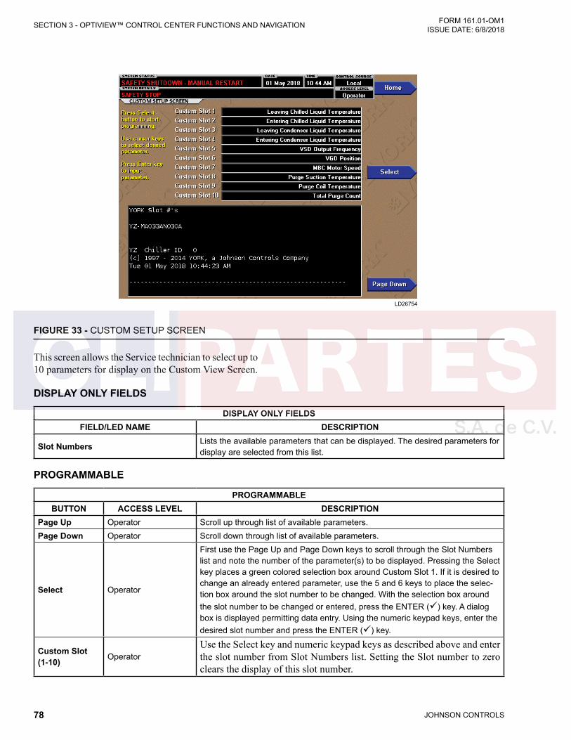
JOHNSON CONTROLS78
FORM 161.01-OM1 ISSUE DATE: 6/8/2018SECTION 3 - OPTIVIEW™ CONTROL CENTER FUNCTIONS AND NAVIGATION
FIGURE 33 - CUSTOM SETUP SCREEN
LD26754
This screen allows the Service technician to select up to 10 parameters for display on the Custom View Screen.
DISPLAY ONLY FIELDS
DISPLAY ONLY FIELDSFIELD/LED NAME DESCRIPTION
Slot Numbers Lists the available parameters that can be displayed. The desired parameters for display are selected from this list.
PROGRAMMABLE
PROGRAMMABLEBUTTON ACCESS LEVEL DESCRIPTION
Page Up Operator Scroll up through list of available parameters.Page Down Operator Scroll down through list of available parameters.
Select Operator
First use the Page Up and Page Down keys to scroll through the Slot Numbers list and note the number of the parameter(s) to be displayed. Pressing the Select key places a green colored selection box around Custom Slot 1. If it is desired to change an already entered parameter, use the 5 and 6 keys to place the selec-tion box around the slot number to be changed. With the selection box around the slot number to be changed or entered, press the ENTER () key. A dialog box is displayed permitting data entry. Using the numeric keypad keys, enter the desired slot number and press the ENTER () key.
Custom Slot (1-10) Operator
Use the Select key and numeric keypad keys as described above and enter the slot number from Slot Numbers list. Setting the Slot number to zero clears the display of this slot number.
JOHNSON CONTROLS 79
SECTION 3 - OPTIVIEW™ CONTROL CENTER FUNCTIONS AND NAVIGATIONFORM 161.01-OM1 ISSUE DATE: 6/8/2018
3
NAVIGATION
NAVIGATIONBUTTON DESCRIPTION
Home Causes an instant return to the Home Screen.Custom View Causes a return to the custom view screen.
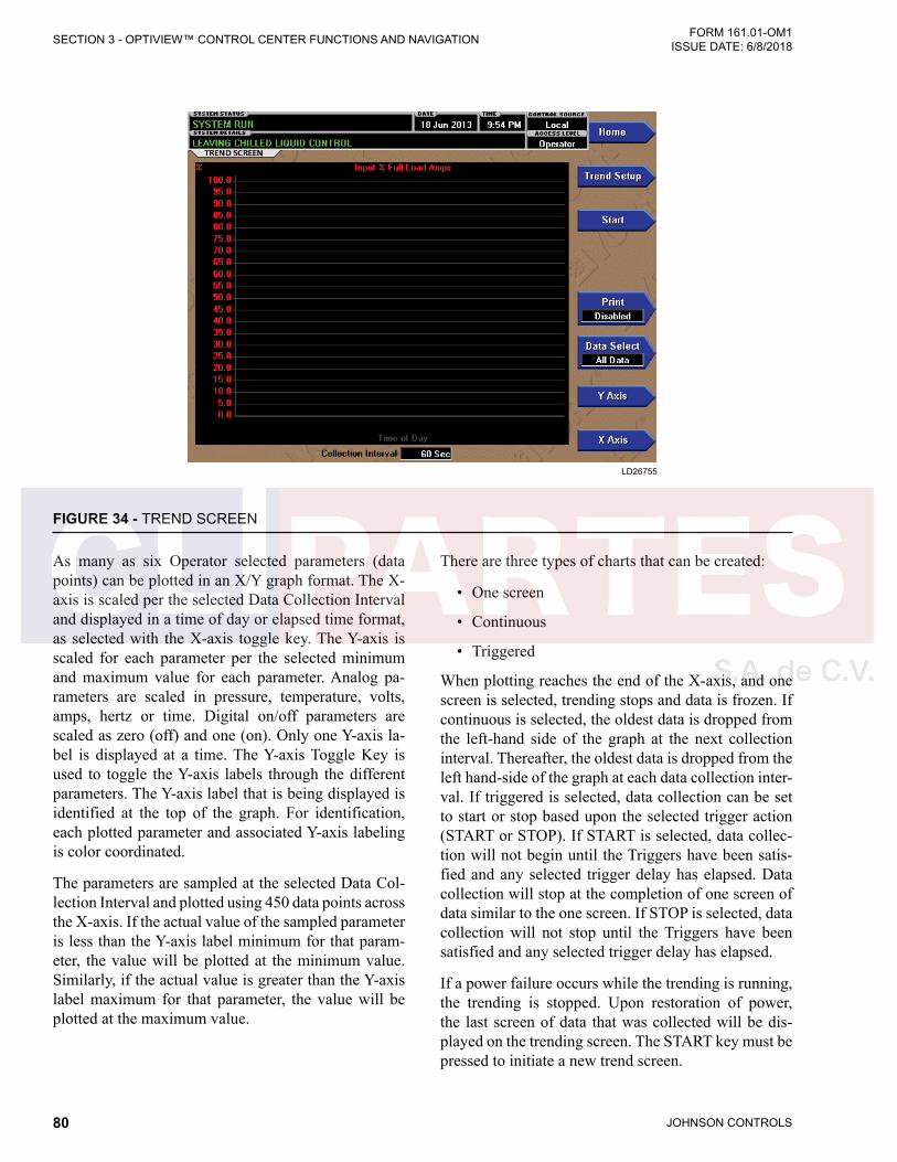
JOHNSON CONTROLS80
FORM 161.01-OM1 ISSUE DATE: 6/8/2018SECTION 3 - OPTIVIEW™ CONTROL CENTER FUNCTIONS AND NAVIGATION
FIGURE 34 - TREND SCREEN
LD26755
As many as six Operator selected parameters (data points) can be plotted in an X/Y graph format. The X-axis is scaled per the selected Data Collection Interval and displayed in a time of day or elapsed time format, as selected with the X-axis toggle key. The Y-axis is scaled for each parameter per the selected minimum and maximum value for each parameter. Analog pa-rameters are scaled in pressure, temperature, volts, amps, hertz or time. Digital on/off parameters are scaled as zero (off) and one (on). Only one Y-axis la-bel is displayed at a time. The Y-axis Toggle Key is used to toggle the Y-axis labels through the different parameters. The Y-axis label that is being displayed is identified at the top of the graph. For identification, each plotted parameter and associated Y-axis labeling is color coordinated.
The parameters are sampled at the selected Data Col-lection Interval and plotted using 450 data points across the X-axis. If the actual value of the sampled parameter is less than the Y-axis label minimum for that param-eter, the value will be plotted at the minimum value. Similarly, if the actual value is greater than the Y-axis label maximum for that parameter, the value will be plotted at the maximum value.
There are three types of charts that can be created:
• One screen
• Continuous
• Triggered
When plotting reaches the end of the X-axis, and one screen is selected, trending stops and data is frozen. If continuous is selected, the oldest data is dropped from the left-hand side of the graph at the next collection interval. Thereafter, the oldest data is dropped from the left hand-side of the graph at each data collection inter-val. If triggered is selected, data collection can be set to start or stop based upon the selected trigger action (START or STOP). If START is selected, data collec-tion will not begin until the Triggers have been satis-fied and any selected trigger delay has elapsed. Data collection will stop at the completion of one screen of data similar to the one screen. If STOP is selected, data collection will not stop until the Triggers have been satisfied and any selected trigger delay has elapsed.
If a power failure occurs while the trending is running, the trending is stopped. Upon restoration of power, the last screen of data that was collected will be dis-played on the trending screen. The START key must be pressed to initiate a new trend screen.
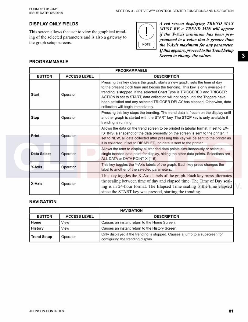
JOHNSON CONTROLS 81
SECTION 3 - OPTIVIEW™ CONTROL CENTER FUNCTIONS AND NAVIGATIONFORM 161.01-OM1 ISSUE DATE: 6/8/2018
3PROGRAMMABLE
PROGRAMMABLEBUTTON ACCESS LEVEL DESCRIPTION
Start Operator
Pressing this key clears the graph, starts a new graph, sets the time of day to the present clock time and begins the trending. This key is only available if trending is stopped. If the selected Chart Type is TRIGGERED and TRIGGER ACTION is set to START, data collection will not begin until the Triggers have been satisfied and any selected TRIGGER DELAY has elapsed. Otherwise, data collection will begin immediately.
Stop OperatorPressing this key stops the trending. The trend data is frozen on the display until another graph is started with the START key. The STOP key is only available if trending is running.
Print Operator
Allows the data on the trend screen to be printed in tabular format. If set to EX-ISTING, a snapshot of the data presently on the screen is sent to the printer. If set to NEW, all data collected after pressing this key will be sent to the printer as it is collected. If set to DISABLED, no data is sent to the printer.
Data Select OperatorAllows the user to display all trended data points simultaneously or select a single trended data point for display, hiding the other data points. Selections are ALL DATA or DATA POINT X (1-6).
Y-Axis OperatorThis key toggles the Y-Axis labels of the graph. Each key press changes the label to another of the selected parameters.
X-Axis Operator
This key toggles the X-Axis labels of the graph. Each key press alternates the scaling between time of day and elapsed time. The Time of Day scal-ing is in 24-hour format. The Elapsed Time scaling is the time elapsed since the START key was pressed, starting the trending.
NAVIGATION
NAVIGATIONBUTTON ACCESS LEVEL DESCRIPTION
Home View Causes an instant return to the Home Screen.History View Causes an instant return to the History Screen.
Trend Setup OperatorOnly displayed if the trending is stopped. Causes a jump to a subscreen for configuring the trending display.
DISPLAY ONLY FIELDSThis screen allows the user to view the graphical trend-ing of the selected parameters and is also a gateway to the graph setup screens.
A red screen displaying TREND MAX MUST BE > TREND MIN will appear if the Y-Axis minimum has been pro-grammed to a value that is greater than the Y-Axis maximum for any parameter. If this appears, proceed to the Trend Setup Screen to change the values.

JOHNSON CONTROLS82
FORM 161.01-OM1 ISSUE DATE: 6/8/2018SECTION 3 - OPTIVIEW™ CONTROL CENTER FUNCTIONS AND NAVIGATION
FIGURE 35 - TREND SETUP SCREEN
LD26756
PROGRAMMABLE
PROGRAMMABLEBUTTON ACCESS LEVEL DESCRIPTION
Chart Type OperatorSelects CONTINUOUS, ONE SCREEN or TRIGGERED. When the Chart Type is set to Triggered, the Triggers button will be displayed providing access to the Advanced Trend Setup Screen.
Collection Interval Operator
Selects the interval at which the parameters are sampled. There are 450 data points displayed across the X-Axis of the graph. Each point represents the instantaneous value of the parameter. The user selects the time interval between these points. This is called the DATA COLLECTION INTERVAL, or the interval at which the parameter is sampled. This interval is programmable over the range of 1 second to 3600 seconds (1 hour), in one second increments. The selected interval not only determines the sample interval, but also the full screen time dis-play. The full screen time display is a result of the selected interval in seconds, multiplied by the 450 data points. To select the desired Data Collection Interval: 1. Determine the desired time interval (in seconds), between data samples. 2. Calculate the full screen time display as follows: • 450 x Data Collection Interval = full screen seconds • full screen seconds / 60 = full screen minutes • full screen minutes / 60 = full screen hours • full screen hours / 24 = full screen days 3. Decide if the resultant sample interval and full screen display meet the
requirements. If not, select a different sample interval.
This screen is used to configure the trending screen. The parameters to be trended are selected from the Common Slots Screen or Common Slots Master list and entered as Slot Numbers for Data Points 1 through
6. The Y-Axis minimum and maximum values for each parameter are entered as Data Point Min and Data Point Max for Data Points 1 through 6. The interval at which all the parameters are sampled is selected as the Data Collection Interval.
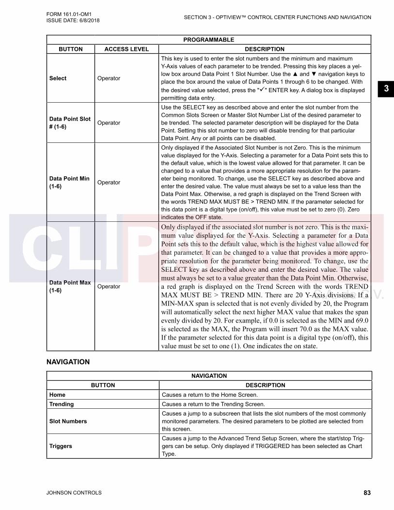
JOHNSON CONTROLS 83
SECTION 3 - OPTIVIEW™ CONTROL CENTER FUNCTIONS AND NAVIGATIONFORM 161.01-OM1 ISSUE DATE: 6/8/2018
3
PROGRAMMABLEBUTTON ACCESS LEVEL DESCRIPTION
Select Operator
This key is used to enter the slot numbers and the minimum and maximum Y-Axis values of each parameter to be trended. Pressing this key places a yel-low box around Data Point 1 Slot Number. Use the ▲ and ▼ navigation keys to place the box around the value of Data Points 1 through 6 to be changed. With the desired value selected, press the "" ENTER key. A dialog box is displayed permitting data entry.
Data Point Slot # (1-6) Operator
Use the SELECT key as described above and enter the slot number from the Common Slots Screen or Master Slot Number List of the desired parameter to be trended. The selected parameter description will be displayed for the Data Point. Setting this slot number to zero will disable trending for that particular Data Point. Any or all points can be disabled.
Data Point Min (1-6) Operator
Only displayed if the Associated Slot Number is not Zero. This is the minimum value displayed for the Y-Axis. Selecting a parameter for a Data Point sets this to the default value, which is the lowest value allowed for that parameter. It can be changed to a value that provides a more appropriate resolution for the param-eter being monitored. To change, use the SELECT key as described above and enter the desired value. The value must always be set to a value less than the Data Point Max. Otherwise, a red graph is displayed on the Trend Screen with the words TREND MAX MUST BE > TREND MIN. If the parameter selected for this data point is a digital type (on/off), this value must be set to zero (0). Zero indicates the OFF state.
Data Point Max (1-6) Operator
Only displayed if the associated slot number is not zero. This is the maxi-mum value displayed for the Y-Axis. Selecting a parameter for a Data Point sets this to the default value, which is the highest value allowed for that parameter. It can be changed to a value that provides a more appro-priate resolution for the parameter being monitored. To change, use the SELECT key as described above and enter the desired value. The value must always be set to a value greater than the Data Point Min. Otherwise, a red graph is displayed on the Trend Screen with the words TREND MAX MUST BE > TREND MIN. There are 20 Y-Axis divisions. If a MIN-MAX span is selected that is not evenly divided by 20, the Program will automatically select the next higher MAX value that makes the span evenly divided by 20. For example, if 0.0 is selected as the MIN and 69.0 is selected as the MAX, the Program will insert 70.0 as the MAX value. If the parameter selected for this data point is a digital type (on/off), this value must be set to one (1). One indicates the on state.
NAVIGATION
NAVIGATIONBUTTON DESCRIPTION
Home Causes a return to the Home Screen.Trending Causes a return to the Trending Screen.
Slot NumbersCauses a jump to a subscreen that lists the slot numbers of the most commonly monitored parameters. The desired parameters to be plotted are selected from this screen.
TriggersCauses a jump to the Advanced Trend Setup Screen, where the start/stop Trig-gers can be setup. Only displayed if TRIGGERED has been selected as Chart Type.
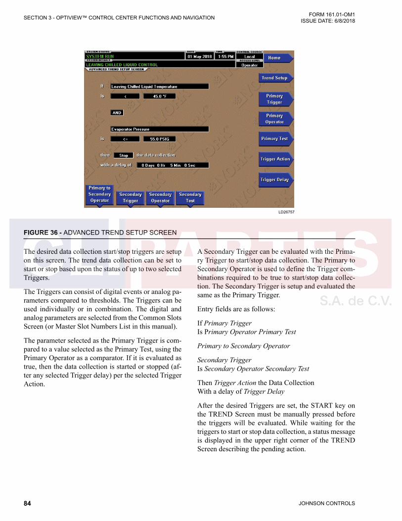
JOHNSON CONTROLS84
FORM 161.01-OM1 ISSUE DATE: 6/8/2018SECTION 3 - OPTIVIEW™ CONTROL CENTER FUNCTIONS AND NAVIGATION
FIGURE 36 - ADVANCED TREND SETUP SCREEN
LD26757
The desired data collection start/stop triggers are setup on this screen. The trend data collection can be set to start or stop based upon the status of up to two selected Triggers.
The Triggers can consist of digital events or analog pa-rameters compared to thresholds. The Triggers can be used individually or in combination. The digital and analog parameters are selected from the Common Slots Screen (or Master Slot Numbers List in this manual).
The parameter selected as the Primary Trigger is com-pared to a value selected as the Primary Test, using the Primary Operator as a comparator. If it is evaluated as true, then the data collection is started or stopped (af-ter any selected Trigger delay) per the selected Trigger Action.
A Secondary Trigger can be evaluated with the Prima-ry Trigger to start/stop data collection. The Primary to Secondary Operator is used to define the Trigger com-binations required to be true to start/stop data collec-tion. The Secondary Trigger is setup and evaluated the same as the Primary Trigger.
Entry fields are as follows:
If Primary Trigger Is Primary Operator Primary Test
Primary to Secondary Operator
Secondary Trigger Is Secondary Operator Secondary Test
Then Trigger Action the Data Collection With a delay of Trigger Delay
After the desired Triggers are set, the START key on the TREND Screen must be manually pressed before the triggers will be evaluated. While waiting for the triggers to start or stop data collection, a status message is displayed in the upper right corner of the TREND Screen describing the pending action.
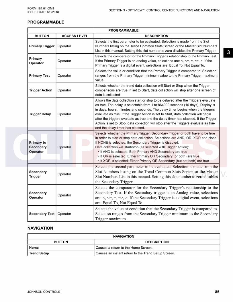
JOHNSON CONTROLS 85
SECTION 3 - OPTIVIEW™ CONTROL CENTER FUNCTIONS AND NAVIGATIONFORM 161.01-OM1 ISSUE DATE: 6/8/2018
3
PROGRAMMABLE
PROGRAMMABLEBUTTON ACCESS LEVEL DESCRIPTION
Primary Trigger OperatorSelects the first parameter to be evaluated. Selection is made from the Slot Numbers listing on the Trend Common Slots Screen or the Master Slot Numbers List in this manual. Setting this slot number to zero disables the Primary Trigger.
Primary Operator Operator
Selects the comparator for the Primary Trigger’s relationship to the Primary Test. If the Primary Trigger is an analog value, selections are: <, <=, =, =>, >. If the Primary Trigger is a digital event, selections are: Equal To, Not Equal To.
Primary Test OperatorSelects the value or condition that the Primary Trigger is compared to. Selection ranges from the Primary Trigger minimum value to the Primary Trigger maximum value.
Trigger Action OperatorSelects whether the trend data collection will Start or Stop when the Trigger comparisons are true. If set to Start, data collection will stop after one screen of data is collected
Trigger Delay Operator
Allows the data collection start or stop to be delayed after the Triggers evaluate as true. The delay is selectable from 1 to 864000 seconds (10 days). Display is in days, hours, minutes and seconds. The delay timer begins when the triggers evaluate as true. If the Trigger Action is set to Start, data collection will begin after the triggers evaluate as true and the delay timer has elapsed. If the Trigger Action is set to Stop, data collection will stop after the Triggers evaluate as true and the delay timer has elapsed.
Primary to Secondary Operator
Operator
Selects whether the Primary Trigger, Secondary Trigger or both have to be true in order to start or stop data collection. Selections are AND, OR, XOR and None. If NONE is selected, the Secondary Trigger is disabled. Data collection will start/stop (as selected with Trigger Action): • If AND is selected: Both Primary AND Secondary are true • If OR is selected: Either Primary OR Secondary (or both) are true • If XOR is selected: Either Primary OR Secondary (but not both) are true
Secondary Trigger Operator
Selects the second parameter to be evaluated. Selection is made from the Slot Numbers listing on the Trend Common Slots Screen or the Master Slot Numbers List in this manual. Setting this slot number to zero disables the Secondary Trigger.
Secondary Operator Operator
Selects the comparator for the Secondary Trigger’s relationship to the Secondary Test. If the Secondary trigger is an Analog value, selections are: <, <=, =, =>, >. If the Secondary Trigger is a digital event, selections are: Equal To, Not Equal To.
Secondary Test OperatorSelects the value or condition that the Secondary Trigger is compared to. Selection ranges from the Secondary Trigger minimum to the Secondary Trigger maximum.
NAVIGATION
NAVIGATIONBUTTON DESCRIPTION
Home Causes a return to the Home Screen.Trend Setup Causes an instant return to the Trend Setup Screen.
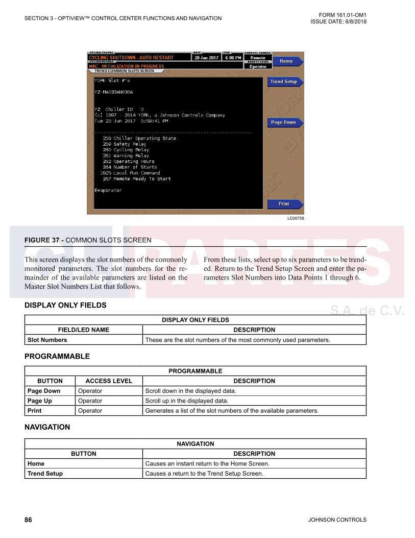
JOHNSON CONTROLS86
FORM 161.01-OM1 ISSUE DATE: 6/8/2018SECTION 3 - OPTIVIEW™ CONTROL CENTER FUNCTIONS AND NAVIGATION
FIGURE 37 - COMMON SLOTS SCREEN
LD26758
DISPLAY ONLY FIELDS
DISPLAY ONLY FIELDSFIELD/LED NAME DESCRIPTION
Slot Numbers These are the slot numbers of the most commonly used parameters.
PROGRAMMABLE
PROGRAMMABLEBUTTON ACCESS LEVEL DESCRIPTION
Page Down Operator Scroll down in the displayed data.Page Up Operator Scroll up in the displayed data.Print Operator Generates a list of the slot numbers of the available parameters.
NAVIGATION
NAVIGATIONBUTTON DESCRIPTION
Home Causes an instant return to the Home Screen.Trend Setup Causes a return to the Trend Setup Screen.
This screen displays the slot numbers of the commonly monitored parameters. The slot numbers for the re-mainder of the available parameters are listed on the Master Slot Numbers List that follows.
From these lists, select up to six parameters to be trend-ed. Return to the Trend Setup Screen and enter the pa-rameters Slot Numbers into Data Points 1 through 6.
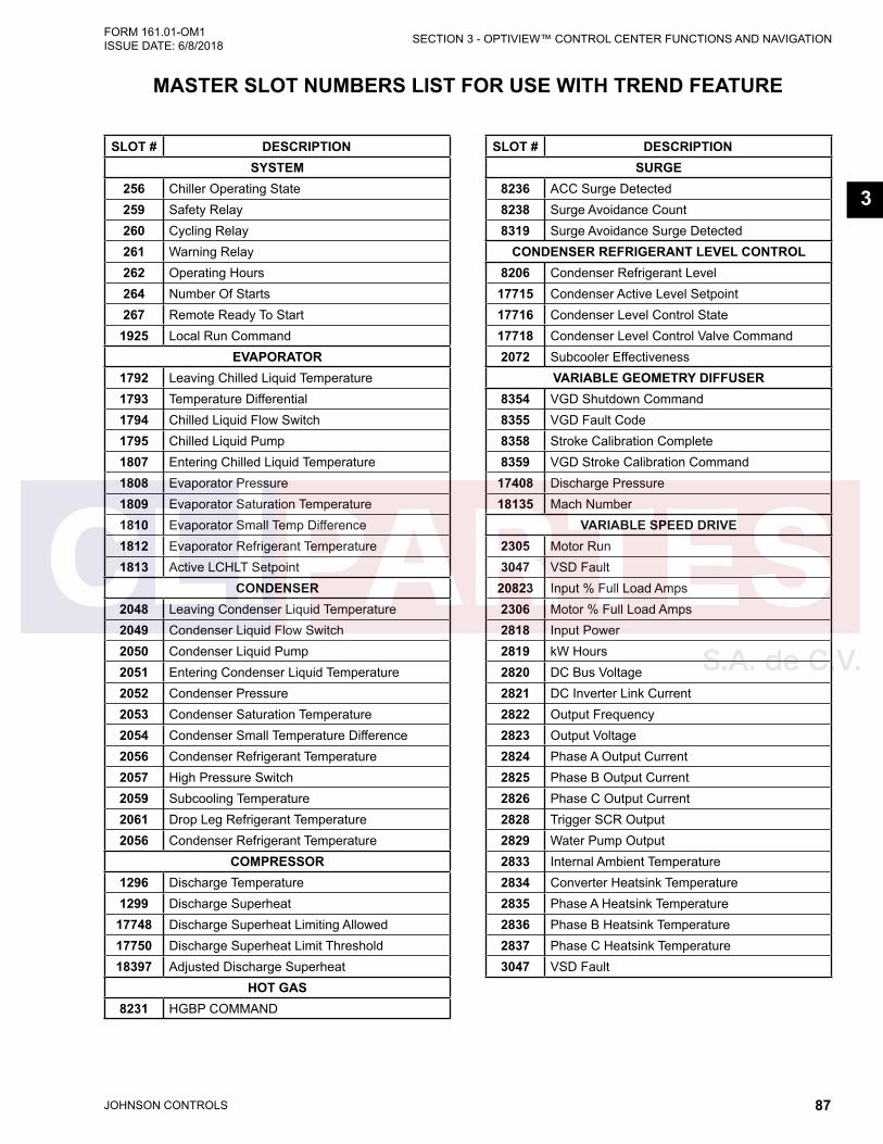
JOHNSON CONTROLS 87
SECTION 3 - OPTIVIEW™ CONTROL CENTER FUNCTIONS AND NAVIGATIONFORM 161.01-OM1 ISSUE DATE: 6/8/2018
3
MASTER SLOT NUMBERS LIST FOR USE WITH TREND FEATURE
SLOT # DESCRIPTIONSYSTEM
256 Chiller Operating State259 Safety Relay260 Cycling Relay261 Warning Relay262 Operating Hours264 Number Of Starts267 Remote Ready To Start
1925 Local Run CommandEVAPORATOR
1792 Leaving Chilled Liquid Temperature1793 Temperature Differential1794 Chilled Liquid Flow Switch1795 Chilled Liquid Pump1807 Entering Chilled Liquid Temperature1808 Evaporator Pressure1809 Evaporator Saturation Temperature1810 Evaporator Small Temp Difference1812 Evaporator Refrigerant Temperature1813 Active LCHLT Setpoint
CONDENSER2048 Leaving Condenser Liquid Temperature2049 Condenser Liquid Flow Switch2050 Condenser Liquid Pump2051 Entering Condenser Liquid Temperature2052 Condenser Pressure2053 Condenser Saturation Temperature2054 Condenser Small Temperature Difference2056 Condenser Refrigerant Temperature2057 High Pressure Switch2059 Subcooling Temperature2061 Drop Leg Refrigerant Temperature2056 Condenser Refrigerant Temperature
COMPRESSOR1296 Discharge Temperature1299 Discharge Superheat
17748 Discharge Superheat Limiting Allowed17750 Discharge Superheat Limit Threshold18397 Adjusted Discharge Superheat
HOT GAS8231 HGBP COMMAND
SLOT # DESCRIPTIONSURGE
8236 ACC Surge Detected8238 Surge Avoidance Count8319 Surge Avoidance Surge Detected
CONDENSER REFRIGERANT LEVEL CONTROL8206 Condenser Refrigerant Level
17715 Condenser Active Level Setpoint17716 Condenser Level Control State17718 Condenser Level Control Valve Command2072 Subcooler Effectiveness
VARIABLE GEOMETRY DIFFUSER8354 VGD Shutdown Command8355 VGD Fault Code8358 Stroke Calibration Complete8359 VGD Stroke Calibration Command
17408 Discharge Pressure18135 Mach Number
VARIABLE SPEED DRIVE2305 Motor Run3047 VSD Fault
20823 Input % Full Load Amps2306 Motor % Full Load Amps2818 Input Power2819 kW Hours2820 DC Bus Voltage2821 DC Inverter Link Current2822 Output Frequency2823 Output Voltage2824 Phase A Output Current2825 Phase B Output Current2826 Phase C Output Current2828 Trigger SCR Output2829 Water Pump Output2833 Internal Ambient Temperature2834 Converter Heatsink Temperature2835 Phase A Heatsink Temperature2836 Phase B Heatsink Temperature2837 Phase C Heatsink Temperature3047 VSD Fault

JOHNSON CONTROLS88
FORM 161.01-OM1 ISSUE DATE: 6/8/2018SECTION 3 - OPTIVIEW™ CONTROL CENTER FUNCTIONS AND NAVIGATION
SLOT # DESCRIPTIONCAPACITY CONTROL
18273 Control State18280 Load Limit18122 VSD Frequency Command20825 VSD Output Frequency18093 Active Anti-Surge Minimum Frequency18300 VGD Command18983 VGD Position18023 HGBP Command18058 Head Pressure18288 Speed of Sound18289 Isentropic Head18290 Omega18291 Surge Mach18332 Anti-Surge Transient Offset18292 Surge Frequency18293 Anti-Surge Minimum Frequency18042 Evaporator Pressure Override Threshold18041 Condenser Pressure Override Threshold20822 Input Current Override Threshold2981 ACC Surge Sensitivity3004 VSD Start Frequency3005 Mapping Enable3006 Quick Ramp Current Threshold2849 ACC Surge Count
MOTOR COOLING20994 Motor Winding Phase A1 temperature20996 Motor Winding Phase B1 temperature20998 Motor Winding Phase C1 temperature20995 Motor Winding Phase A2 temperature20997 Motor Winding Phase B2 temperature20999 Motor Winding Phase C2 temperature19148 Average Winding Temperature8751 Motor Housing Temperature8707 Motor Housing Temperature Setpoint8752 Motor Winding Temperature Setpoint8723 Ambient Dew Point Temperature8708 Motor Cooling Valve Command8710 Motor Cooling Control State
MBC24032 MBC Command23860 MBC Control Mode23809 MBC Levitated Contact24033 MBC Levitated23808 MBC Fault
SLOT # DESCRIPTION23844 MBC Motor Speed23849 MBC Heatsink Temperature23845 J Bearing Temperature23848 K Bearing Temperature23846 H1 Bearing Temperature23847 H2 Bearing Temperature23829 J Average Position X23830 J Average Position Y23833 H Average Position23831 K Average Position X23832 K Average Position Y23824 J Synchronous Orbit X23825 J Synchronous Orbit Y23828 H Synchronous Orbit 23826 K Synchronous Orbit X23827 K Synchronous Orbit Y23834 J Standard Deviation X23835 J Standard Deviation Y23838 H Standard Deviation23836 K Standard Deviation X23837 K Standard Deviation Y23819 J Peak Vibration23821 H Peak Vibration23820 K Peak Vibration23822 J Average Gap Change23823 K Average Gap Change23839 J Average Force X23840 J Average Force Y23843 H Average Force23841 K Average Force X23842 K Average Force Y23850 J1 Current23851 J2 Current23852 J3 Current23853 J4 Current23858 H1 Current23859 H2 Current23854 K1 Current23855 K2 Current23856 K3 Current23857 K4 Current

JOHNSON CONTROLS 89
SECTION 3 - OPTIVIEW™ CONTROL CENTER FUNCTIONS AND NAVIGATIONFORM 161.01-OM1 ISSUE DATE: 6/8/2018
3
SLOT # DESCRIPTIONUPS
24354 Control Voltage24353 Power Loss Time24355 UPS Line/Charging24356 UPS Inverter24357 UPS Fault24360 UPS Battery Voltage24358 UPS Inverter Enable
PURGE24322 Purge Control State24323 Purge State Timer24324 Purge Compressor Run24325 Purge Pump Run24326 Enhanced State Count24327 Total Purge Count24329 User Purge Count24332 Purge Tank High Level24333 Purge Suction Temperature24334 Purge Coil Temperature24335 Regeneration Tank Drain Solenoid24336 Regeneration Tank Heater24337 Regeneration Tank Temperature

JOHNSON CONTROLS90
FORM 161.01-OM1 ISSUE DATE: 6/8/2018SECTION 3 - OPTIVIEW™ CONTROL CENTER FUNCTIONS AND NAVIGATION
DISPLAY MESSAGESThe Status Bar of the Display contains a Status Line and, beneath it a Details Line. The Status Line contains a message describing the operating state of the chill-er; whether it is stopped, running, starting or shutting down. The Details Line displays Warning, Cycling, Safety, Start Inhibit and other messages that provide further details of the Status Bar messages. The Status Messages listed below are displayed on the Status Line. All other messages are displayed on the Details Line. For convenience they are listed in alphabetical order.
To aid in the meaning of the message, messages are displayed in different colors as follows:
• Normal Operation messages - Green• Warning messages - Yellow• Cycling Shutdown messages - Orange• Safety Shutdown messages - Red
Warning messages will scroll between all those stand-ing. Shutdowns will show first occurrence.
TABLE 5 - STATUS MESSAGESMESSAGE DESCRIPTION
CYCLING SHUTDOWN – AUTO RESTART
The chiller is shut down on a CYCLING shutdown. The cause of the shutdown is still in effect and is displayed on the Details line of the Status Bar. The chiller will automatically restart when the CYCLING condition clears.
MBC STARTUPA chiller start has been initiated. The MBC conditions are verified and transitional to levitate the driveline rotor (MBC Levitation Mode). The progress of the MBC startup is described in the Details Line of the Status Bar.
SAFETY SHUTDOWN – MANUAL RESTART
The chiller is shut down on a SAFETY shutdown. The cause of the shutdown is still in effect and is displayed on the Details line of the Status Bar. The chiller can be started after the Safety con-dition clears and the Operator presses the CLEAR FAULT key.
SOFT SHUTDOWN
The chiller is performing a Soft Shutdown. Simultaneously, the Hot Gas Bypass Valve is com-manded to 100% open (if Hot Gas Bypass is Enabled), the compressor VGD commanded to close rapidly. The motor drive speed is slowed from its initial speed to the minimum required to prevent surge. Then the motor drive speed is ramped to 0 Hz. The chiller then transitions to coastdown. Soft Shutdown in initiated by the following: • Leaving Chilled Liquid – Low Temperature • Local Panel Stop Key • Remote Stop • Any MBC Fault occurs • Multi-Unit Cycling – Contacts Open • System Cycling – Contacts Open • Control Panel – Schedule • "Condenser – Flow Switch Open" fault active • "Chilled Liquid – Flow Switch Open" fault active • "Expansion I/O – Serial Communications" fault activeIf the local panel safety stop switch is pressed or any chiller shutdown faults other than those listed above occur, Soft Shutdown is immediately terminated and a System Coastdown will oc-cur.
START INHIBIT The chiller is prevented from being started due to the reason displayed on the Details Line of the Status bar.
SYSTEM COASTDOWN
The chiller has shut down and removed the run signal from the motor variable speed drive (VSD). The system is waiting for confirmation that the driveline has stopped rotating. When the MBC and VSD report drive frequency of 0Hz for 5 seconds, coastdown is considered completed. Then, after 60 seconds delay the VSD Precharge command is released.
SYSTEM READY TO START
The chiller is shut down but will initiate start upon receipt of a Local or Remote start signal. The Magnetic Bearing Controller (MBC) does not have the driveline rotor levitated. The Hot Gas Bypass Valve position (if present) is set to the programmed Hot Gas Startup Position. The Level Control Valve position is set to the programmed Condenser Level Control Valve Startup Position. The VGD driven to the programmed VGD Startup Position.
SYSTEM RUN The chiller is running under the condition described in the Details Line of the Status Bar. SYSTEM STOPPED The chiller is shutdown with a prevailing stop command.

JOHNSON CONTROLS 91
SECTION 3 - OPTIVIEW™ CONTROL CENTER FUNCTIONS AND NAVIGATIONFORM 161.01-OM1 ISSUE DATE: 6/8/2018
3
TABLE 6 - RUN MESSAGESMESSAGE DESCRIPTION
LEAVING CHILLED LIQUID CONTROL
The chiller is running, controlling the Leaving Chilled Liquid to the Leaving Chilled Liquid Temperature Setpoint. No system conditions is inhibiting this operation.
WARNING – VSD DC BUS ACTIVE
This non-annunciating message alerts that the DC Bus is precharged or pre-regulated for a state outside of chiller run. It is set when the VSD indicates a precharge or pre-regulated state or DC Bus voltage >50v in the stopped state. A countdown timer shows with this message to indicate the time remaining in a precharge or pre-regulate com-mand while stopped.
VSD – HIGH INPUT CURRENT LIMIT
The Chiller Input current is greater than or equal to the Active Current Limit Setpoint. The Current Limit Setpoint is programmed over a range of 30 to 100% of the Chiller Full Load Amps (FLA). The Active limit is the minimum of the Local, pulldown (if active), and Remote Current Limit Setpoints in Remote mode or the remote value in BAS mode. While this condition is in effect, chiller capacity control is in override to reduce current. Normal LCHLT capacity control operation is resumed and this message automatically clears when the input current decreases below this limit. The highest of the three phase input currents divided by the programmed Job Input FLA is compared to the limit for this override..
VSD – INPUT PULLDOWN LIMIT The chiller input current will be limited by the pulldown demand limit setpoint. The mes-sage clears when the pulldown demand time expires.
TABLE 7 - MBC STARTUP MESSAGESMESSAGE DESCRIPTION
WAITING FOR FLOWThe chilled liquid or condenser flow switch input is not reading voltage indicating no presence of flow from the flow switch. Indication of flow is required during the M Startup state to allow transition to chiller run.
WAITING FOR MBC LEVITATION
The OptiView has issued a MBC Levitate command to the MBC and is waiting for confirmation from the MBC that the Levitated mode is ON, and the input from the digital contacts on the MBC is high at OptiView I/O board terminal TB15-18. This message precedes “Waiting for Chilled Liquid Flow”.
WAITING FOR VSD PREREGULATION
The OptiView has issued a VSD Pre-Charge command to the VSD and is waiting for confirmation from the VSD that it has achieved regulated DC bus voltage and is await-ing a run command. This message precedes “Waiting for MBC Levitation”.
WAITING FOR ZERO MOTOR SPEED
The Motor Speed is > 0.001Hz. The message will be removed when the motor speed is <= 0.001Hz.
TABLE 8 - START INHIBIT MESSAGESMESSAGE DESCRIPTION
LINE FREQUENCY NOT SET This start inhibit is set when the Line Frequency setpoint is “INVALID”. Line Frequency is set invalid on a new or cleared Flash Memory until programmed.
LINE VOLTAGE NOT SET This start inhibit is set when the Line Voltage setpoint is “INVALID”. Line Voltage is set invalid on a new or cleared Flash Memory until programmed.
VGD STROKE NOT CALIBRATED The Variable Geometry Diffuser stroke calibration procedure has NOT yet been per-formed.
VGD ACTUATOR FEEDBACK NOT CALIBRATED
The Variable Geometry Diffuser feedback calibration has not yet been performed.
MBC - INITIALIZATION FAILURE
OptiView was unable to read a valid validation key code over serial communications from the MBC.
MBC - INITIALIZATION IN PROGRESS
OptiView is initializing communications with the MBC.

JOHNSON CONTROLS92
FORM 161.01-OM1 ISSUE DATE: 6/8/2018SECTION 3 - OPTIVIEW™ CONTROL CENTER FUNCTIONS AND NAVIGATION
TABLE 9 - WARNING MESSAGESMESSAGE DESCRIPTION
WARNING - CONDENSER FREEZE THREAT FROM LOW PRESSURE
While the chiller state is Stopped, the Saturated Condenser Temperature decreased below 35.0 °F (1.7 °C). The condenser pump run contacts close. The message is auto-matically reset and pump contacts return to prior state when either the chiller is not in stopped state or the Saturated Condenser Temperature > 40.0 °F (4.4 °C).
WARNING – CONDENSER – HIGH PRESSURE LIMIT
The Condenser Pressure exceeds the High Pressure Warning Setpoint threshold, programmed by a Service technician logged in at SERVICE access level. While this condition is in effect, the chiller capacity is in override to reduce pressure. This message automatically clears and normal LCHLT capacity control restored when the Condenser pressure decreases to below the Setpoint.
WARNING – CONDENSER OR EVAPORATOR XDCR ERROR
The Evaporator pressure Transducer is indicating a higher pressure than the Condenser pressure Transducer after the chiller has been running for 10 minutes. This is indicative of a Condenser or Evaporator Transducer failure. This message will be displayed until the condition clears and the WARNING RESET Keypad key is pressed in OPERATOR (or higher) access mode. Condition not checked in Brine mode.
WARNING – CONDENSER OR VGD SENSOR FAILURE
The difference between the Discharge Pressure Transducer output and the Condenser Pressure Transducer output has exceeded 21 PSID for 3 continuous minutes while the chiller was running. This feature verifies the operation of the transducers. Since both transducers are measuring essentially the same pressure, both outputs should be within the specified tolerance. This message must be manually cleared. It will be displayed un-til the transducer outputs are within the acceptable range of each other and the WARN-ING RESET key in SERVICE access level.
WARNING – HARMONIC FILTER - INVALID MODEL
This warning is set when the Harmonic Filter Model is invalid. The warning is rest when the filter model is valid or the filter operation is inhibited.
WARNING – MBC SPEED SIGNAL FAULT
The speed signal from the Speed Sensor 1 is not reading. The chiller will continue to run and the warning message will clear when the speed sensor signal is reading again.
WARNING - LIQUID LEVEL SETPOINT NOT ACHIEVED
The chiller is running and Refrigerant Level > (Refrigerant Level setpoint +15%) OR Refrigerant Level < (Refrigerant Level setpoint -15%) for 10 continuous minutes. The Warning is bypassed for the first 30 minutes of run to allow stabile operation to estab-lish. It is released when the chiller is not running or Refrigerant Level is within setpoint +- 15%. The message clears automatically.
WARNING - LOSS OF SUBCOOLER LIQUID SEAL
The chiller is running greater than 30 minutes and the Subcooler Effectiveness value decreased less than 0.400 (ADMIN programmable) at any drop leg refrigerant tempera-ture or increased greater than 1.50 (ADMIN programmable) when the drop leg refriger-ant temperature is at least 0.5 °F (-17.5 °C) below or any amount above the Entering Condenser Liquid Temperature. The subcooler effectiveness is (Condenser Sat Temp - Drop leg refrigerant temp)/(Cond Sat Temp - Entering Condenser Liquid Temp). To clear message press WARNING RESET key on HOME Screen when logged in at OPERA-TOR (or higher) access level.
WARNING – MBC – LOW AMPLIFIER RESISTANCE
This warning is displayed when any of the MBC Amplifier resistances are low.
WARNING – MBC – HIGH AMPLIFIER RESISTANCE
This warning is displayed when any of the MBC Amplifier resistances are high.
WARNING – MBC – LOW AMPLIFIER CURRENT
This warning is displayed when any of the MBC Amplifier currents are low.
WARNING – MBC – HIGH AMPLIFIER CURRENT
This warning is displayed when any of the MBC Amplifier currents are high.
WARNING – MBC – POSITION SENSOR ERROR
This warning is displayed when any of the MBC Position Sensors read in error.
WARNING – MBC – INTERNAL ALARM
The MBC experienced an unsatisfactory condition detected internally to the control sys-tem. This message will clear when the condition is resolved and the WARNING RESET key is pressed in OPERATOR (or higher) access mode.
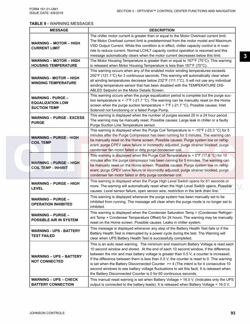
JOHNSON CONTROLS 93
SECTION 3 - OPTIVIEW™ CONTROL CENTER FUNCTIONS AND NAVIGATIONFORM 161.01-OM1 ISSUE DATE: 6/8/2018
3
MESSAGE DESCRIPTION
WARNING – MOTOR – HIGH CURRENT LIMIT
The chiller motor current is greater than or equal to the Motor Overload current limit. The Motor Overload current limit is predetermined from the motor model and Maximum VSD Output Current. While this condition is in effect, chiller capacity control is in over-ride to reduce current. Normal LCHLT capacity control operation is resumed and this message automatically clears when the motor current decreases below this limit.
WARNING – MOTOR – HIGH HOUSING TEMPERATURE
The Motor Housing Temperature is greater than or equal to 167°F (75°C). This warning is released when Motor Housing Temperature is less than 167°F (70°C).
WARNING - MOTOR – HIGH WINDING TEMPERATURE
This warning occurs when any of the enabled motor winding temperatures exceeds 250°F (121.1°C) for 3 continuous seconds. This warning will automatically clear when all winding temperatures decrease below 232°F (111.1°C). It will not use any individual winding temperature sensor that has been disabled with the TEMPERATURE DIS-ABLED Setpoint on the Motor Details Screen.
WARNING - PURGE – EQUALIZATION LOW SUCTION TEMP
This warning occurs when the purge equalization period is complete but the purge suc-tion temperature is < -7°F (-21.7 °C). The warning can be manually reset on the Home screen when the purge suction temperature > 7°F (-21.7 °C). Possible causes: Inlet Solenoid not functioning or a failed Purge Pump.
WARNING – PURGE - EXCESS PURGE
This warning is displayed when the number of purges exceed 20 in a 24 hour period. The warning may be manually reset. Possible causes: Large leak in chiller or a faulty Purge Suction Line Temperature sensor.
WARNING – PURGE - HIGH COIL TEMP
This warning is displayed when the Purge Coil Temperature is > -10°F (-23.3 °C) for 5 minutes after the Purge Compressor has been running for 5 minutes. The warning can be manually reset on the Home screen. Possible causes: Purge system low on refrig-erant, purge CPEV valve failure or incorrectly adjusted, purge strainer blocked, purge condenser fan motor failed or dirty purge condenser coil.
WARNING – PURGE – HIGH COIL TEMP - INHIBIT
This warning is displayed when the Purge Coil Temperature is > 0°F (17.8 °C) for 10 minutes after the purge compressor has been running for 5 minutes. The warning can be manually reset on the Home screen. Possible causes: Purge system low on refrig-erant, purge CPEV valve failure or incorrectly adjusted, purge strainer blocked, purge condenser fan motor failed or dirty purge condenser coil.
WARNING – PURGE – HIGH LEVEL
This warning is displayed when the Purge High Level Switch opens for 61 seconds or more. The warning will automatically reset when the High Level Switch opens. Possible causes: Level sensor failure, open sensor wire, restriction in the tank drain line.
WARNING – PURGE – OPERATION INHIBITED
This warning is displayed whenever the purge system has been manually set to be inhibited from running. The message will clear when the purge mode is no longer set to inhibited.
WARNING – PURGE – POSSIBLE AIR IN SYSTEM
This warning is displayed when the Condenser Saturation Temp > (Condenser Refriger-ant Temp + Condenser Temperature Offset) for 24 hours. The warning may be manually reset on the Home screen. Possible causes: Leaks in chiller system.
WARNING - UPS - BATTERY TEST FAILED
This message is displayed whenever any step of the Battery Health Test fails or if the Battery Health Test is interrupted by a power cycle during the test. The Warning will clear when UPS Battery Health Test is successfully completed.
WARNING – UPS – BATTERY NOT CONNECTED
This is an auto reset warning. The minimum and maximum Battery Voltage is read each 10 second window and stored. At the end of each 10 second window, if the difference between the min and max battery voltage is greater than 0.5 V, a counter is increased. If the difference between them is less than 0.5 V, the counter is reset to 0. This warning is set when the Battery Disconnected Counter >= 4 (The intent is for 4 consecutive 10 second windows to see battery voltage fluctuations to set this fault. It is released when the Battery Disconnected Counter is 0 for 60 continuous seconds.
WARNING – UPS – CHECK BATTERY CONNECTION
This manual reset warning is set when Battery Voltage > 16.0 V. (Indicates only the UPS output is connected to the battery leads). It is released when Battery Voltage < 16.0 V.
TABLE 9 - WARNING MESSAGES
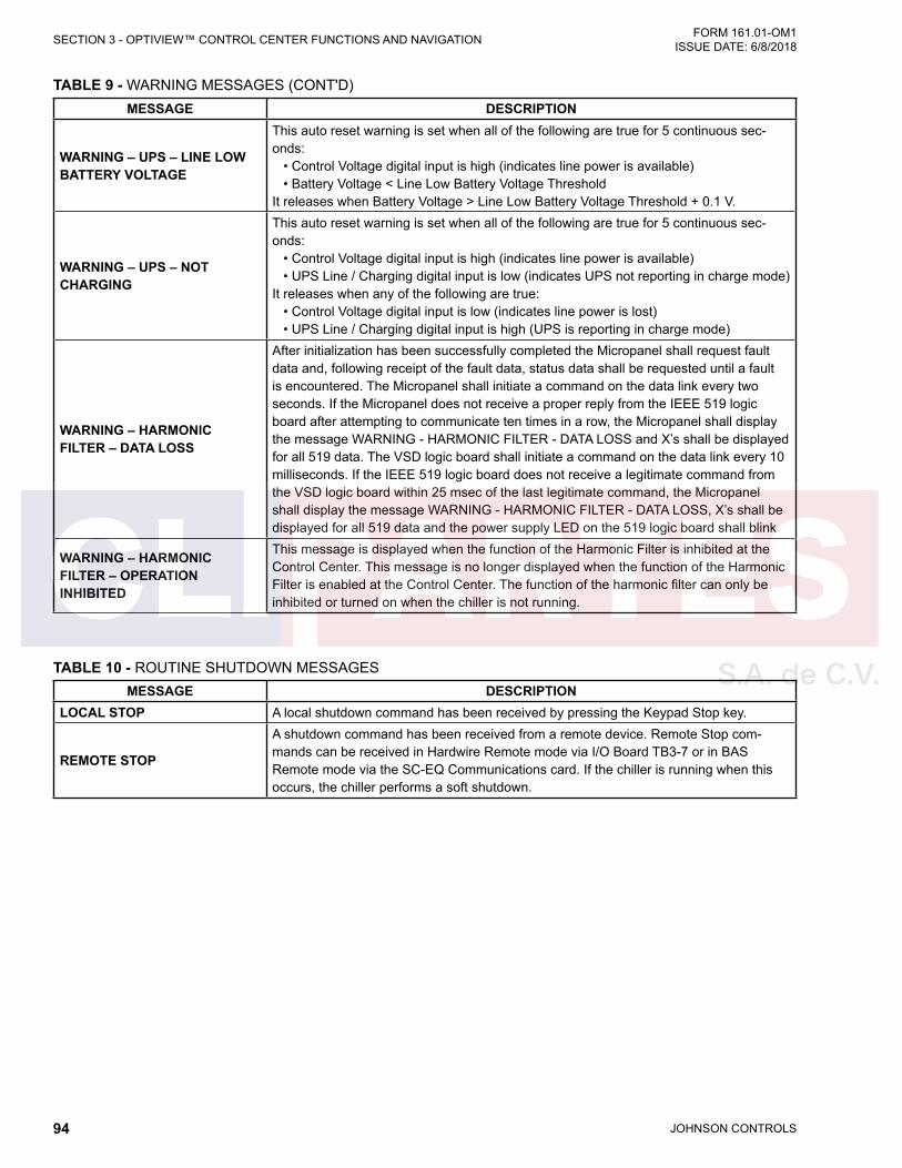
JOHNSON CONTROLS94
FORM 161.01-OM1 ISSUE DATE: 6/8/2018SECTION 3 - OPTIVIEW™ CONTROL CENTER FUNCTIONS AND NAVIGATION
MESSAGE DESCRIPTION
WARNING – UPS – LINE LOW BATTERY VOLTAGE
This auto reset warning is set when all of the following are true for 5 continuous sec-onds: • Control Voltage digital input is high (indicates line power is available) • Battery Voltage < Line Low Battery Voltage ThresholdIt releases when Battery Voltage > Line Low Battery Voltage Threshold + 0.1 V.
WARNING – UPS – NOT CHARGING
This auto reset warning is set when all of the following are true for 5 continuous sec-onds: • Control Voltage digital input is high (indicates line power is available) • UPS Line / Charging digital input is low (indicates UPS not reporting in charge mode)It releases when any of the following are true: • Control Voltage digital input is low (indicates line power is lost) • UPS Line / Charging digital input is high (UPS is reporting in charge mode)
WARNING – HARMONIC FILTER – DATA LOSS
After initialization has been successfully completed the Micropanel shall request fault data and, following receipt of the fault data, status data shall be requested until a fault is encountered. The Micropanel shall initiate a command on the data link every two seconds. If the Micropanel does not receive a proper reply from the IEEE 519 logic board after attempting to communicate ten times in a row, the Micropanel shall display the message WARNING - HARMONIC FILTER - DATA LOSS and X’s shall be displayed for all 519 data. The VSD logic board shall initiate a command on the data link every 10 milliseconds. If the IEEE 519 logic board does not receive a legitimate command from the VSD logic board within 25 msec of the last legitimate command, the Micropanel shall display the message WARNING - HARMONIC FILTER - DATA LOSS, X’s shall be displayed for all 519 data and the power supply LED on the 519 logic board shall blink
WARNING – HARMONIC FILTER – OPERATION INHIBITED
This message is displayed when the function of the Harmonic Filter is inhibited at the Control Center. This message is no longer displayed when the function of the Harmonic Filter is enabled at the Control Center. The function of the harmonic filter can only be inhibited or turned on when the chiller is not running.
TABLE 10 - ROUTINE SHUTDOWN MESSAGESMESSAGE DESCRIPTION
LOCAL STOP A local shutdown command has been received by pressing the Keypad Stop key.
REMOTE STOP
A shutdown command has been received from a remote device. Remote Stop com-mands can be received in Hardwire Remote mode via I/O Board TB3-7 or in BAS Remote mode via the SC-EQ Communications card. If the chiller is running when this occurs, the chiller performs a soft shutdown.
TABLE 9 - WARNING MESSAGES (CONT'D)
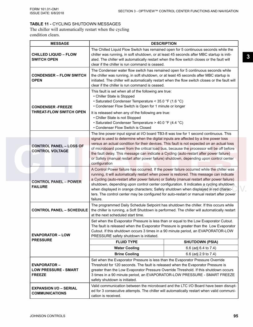
JOHNSON CONTROLS 95
SECTION 3 - OPTIVIEW™ CONTROL CENTER FUNCTIONS AND NAVIGATIONFORM 161.01-OM1 ISSUE DATE: 6/8/2018
3
MESSAGE DESCRIPTION
CHILLED LIQUID – FLOW SWITCH OPEN
The Chilled Liquid Flow Switch has remained open for 5 continuous seconds while the chiller was running, in soft shutdown, or at least 45 seconds after MBC startup is initi-ated. The chiller will automatically restart when the flow switch closes or the fault will clear if the chiller is run command is ceased.
CONDENSER – FLOW SWITCH OPEN
The Condenser water flow switch has remained open for 5 continuous seconds while the chiller was running, in soft shutdown, or at least 45 seconds after MBC startup is initiated. The chiller will automatically restart when the flow switch closes or the fault will clear if the chiller is run command is ceased.
CONDENSER -FREEZE THREAT-FLOW SWITCH OPEN
This fault is set when all of the following are true: • Chiller State is Stopped • Saturated Condenser Temperature < 35.0 °F (1.6 °C) • Condenser Flow Switch is Open for 1 minute or longer
It is released when any of the following are true: • Chiller State is not Stopped • Saturated Condenser Temperature > 40.0 °F (4.4 °C) • Condenser Flow Switch is Closed
CONTROL PANEL – LOSS OF CONTROL VOLTAGE
The line power input signal at I/O board TB3-8 was low for 1 second continuous. This signal is used to determine when the digital inputs are affected by a line power loss versus an actual condition for their devices. This fault is not expected on an actual loss of microboard power from the critical load bus, because the processor will be off before the fault delay. This message can indicate a Cycling (auto-restart after power failure) or Safety (manual restart after power failure) shutdown, depending upon control center configuration
CONTROL PANEL – POWER FAILURE
A Control Power failure has occurred. If the power failure occurred while the chiller was running, it will automatically restart when power is restored. This message can indicate a Cycling (auto-restart after power failure) or Safety (manual restart after power failure) shutdown, depending upon control center configuration. It indicates a cycling shutdown when displayed in orange characters; Safety shutdown when displayed in red charac-ters. The control center may be configured for auto-restart or manual restart after power failure.
CONTROL PANEL – SCHEDULEThe programmed Daily Schedule Setpoint has shutdown the chiller. If this occurs while the chiller is running, a Soft Shutdown is performed. The chiller will automatically restart at the next scheduled start time.
EVAPORATOR – LOW PRESSURE
Set when the Evaporator Pressure is less than or equal to the Low Evaporator Cutout. The fault is released when the Evaporator Pressure is greater than the Low Evaporator Cutout. If this shutdown occurs 3 times in a 90 minute period, an EVAPORATOR-LOW PRESSURE safety shutdown is initiated.
FLUID TYPE SHUTDOWN (PSIA)Water Cooling 6.6 (adj 6.4 to 7.4)Brine Cooling 6.6 (adj 2.9 to 7.4)
EVAPORATOR – LOW PRESSURE - SMART FREEZE
Set when the Evaporator Pressure is less than the Evaporator Pressure Override Threshold for 120 seconds. The fault is released when the Evaporator Pressure is greater than the Low Evaporator Pressure Override Threshold. If this shutdown occurs 3 times in a 90 minute period, an EVAPORATOR-LOW PRESSURE - SMART FREEZE safety shutdown is initiated.
EXPANSION I/O – SERIAL COMMUNICATIONS
Valid communication between the microboard and the LTC I/O Board have been disrupt-ed for 3 consecutive attempts. The chiller will automatically restart when valid communi-cation is received.
TABLE 11 - CYCLING SHUTDOWN MESSAGESThe chiller will automatically restart when the cycling condition clears.
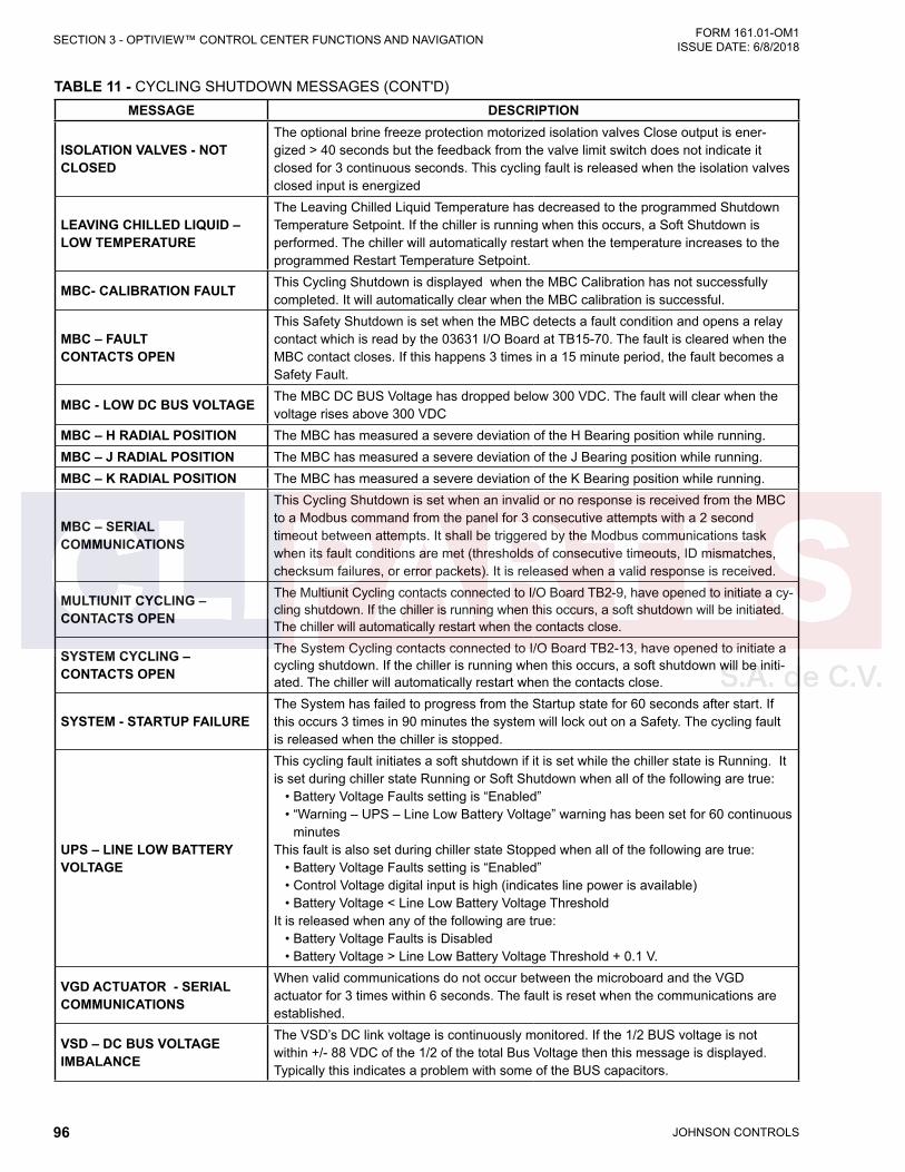
JOHNSON CONTROLS96
FORM 161.01-OM1 ISSUE DATE: 6/8/2018SECTION 3 - OPTIVIEW™ CONTROL CENTER FUNCTIONS AND NAVIGATION
MESSAGE DESCRIPTION
ISOLATION VALVES - NOT CLOSED
The optional brine freeze protection motorized isolation valves Close output is ener-gized > 40 seconds but the feedback from the valve limit switch does not indicate it closed for 3 continuous seconds. This cycling fault is released when the isolation valves closed input is energized
LEAVING CHILLED LIQUID – LOW TEMPERATURE
The Leaving Chilled Liquid Temperature has decreased to the programmed Shutdown Temperature Setpoint. If the chiller is running when this occurs, a Soft Shutdown is performed. The chiller will automatically restart when the temperature increases to the programmed Restart Temperature Setpoint.
MBC- CALIBRATION FAULT This Cycling Shutdown is displayed when the MBC Calibration has not successfully completed. It will automatically clear when the MBC calibration is successful.
MBC – FAULT CONTACTS OPEN
This Safety Shutdown is set when the MBC detects a fault condition and opens a relay contact which is read by the 03631 I/O Board at TB15-70. The fault is cleared when the MBC contact closes. If this happens 3 times in a 15 minute period, the fault becomes a Safety Fault.
MBC - LOW DC BUS VOLTAGE The MBC DC BUS Voltage has dropped below 300 VDC. The fault will clear when the voltage rises above 300 VDC
MBC – H RADIAL POSITION The MBC has measured a severe deviation of the H Bearing position while running.MBC – J RADIAL POSITION The MBC has measured a severe deviation of the J Bearing position while running.MBC – K RADIAL POSITION The MBC has measured a severe deviation of the K Bearing position while running.
MBC – SERIAL COMMUNICATIONS
This Cycling Shutdown is set when an invalid or no response is received from the MBC to a Modbus command from the panel for 3 consecutive attempts with a 2 second timeout between attempts. It shall be triggered by the Modbus communications task when its fault conditions are met (thresholds of consecutive timeouts, ID mismatches, checksum failures, or error packets). It is released when a valid response is received.
MULTIUNIT CYCLING – CONTACTS OPEN
The Multiunit Cycling contacts connected to I/O Board TB2-9, have opened to initiate a cy-cling shutdown. If the chiller is running when this occurs, a soft shutdown will be initiated. The chiller will automatically restart when the contacts close.
SYSTEM CYCLING – CONTACTS OPEN
The System Cycling contacts connected to I/O Board TB2-13, have opened to initiate a cycling shutdown. If the chiller is running when this occurs, a soft shutdown will be initi-ated. The chiller will automatically restart when the contacts close.
SYSTEM - STARTUP FAILUREThe System has failed to progress from the Startup state for 60 seconds after start. If this occurs 3 times in 90 minutes the system will lock out on a Safety. The cycling fault is released when the chiller is stopped.
UPS – LINE LOW BATTERY VOLTAGE
This cycling fault initiates a soft shutdown if it is set while the chiller state is Running. It is set during chiller state Running or Soft Shutdown when all of the following are true: • Battery Voltage Faults setting is “Enabled” • “Warning – UPS – Line Low Battery Voltage” warning has been set for 60 continuous
minutesThis fault is also set during chiller state Stopped when all of the following are true: • Battery Voltage Faults setting is “Enabled” • Control Voltage digital input is high (indicates line power is available) • Battery Voltage < Line Low Battery Voltage ThresholdIt is released when any of the following are true: • Battery Voltage Faults is Disabled • Battery Voltage > Line Low Battery Voltage Threshold + 0.1 V.
VGD ACTUATOR - SERIAL COMMUNICATIONS
When valid communications do not occur between the microboard and the VGD actuator for 3 times within 6 seconds. The fault is reset when the communications are established.
VSD – DC BUS VOLTAGE IMBALANCE
The VSD’s DC link voltage is continuously monitored. If the 1/2 BUS voltage is not within +/- 88 VDC of the 1/2 of the total Bus Voltage then this message is displayed. Typically this indicates a problem with some of the BUS capacitors.
TABLE 11 - CYCLING SHUTDOWN MESSAGES (CONT'D)
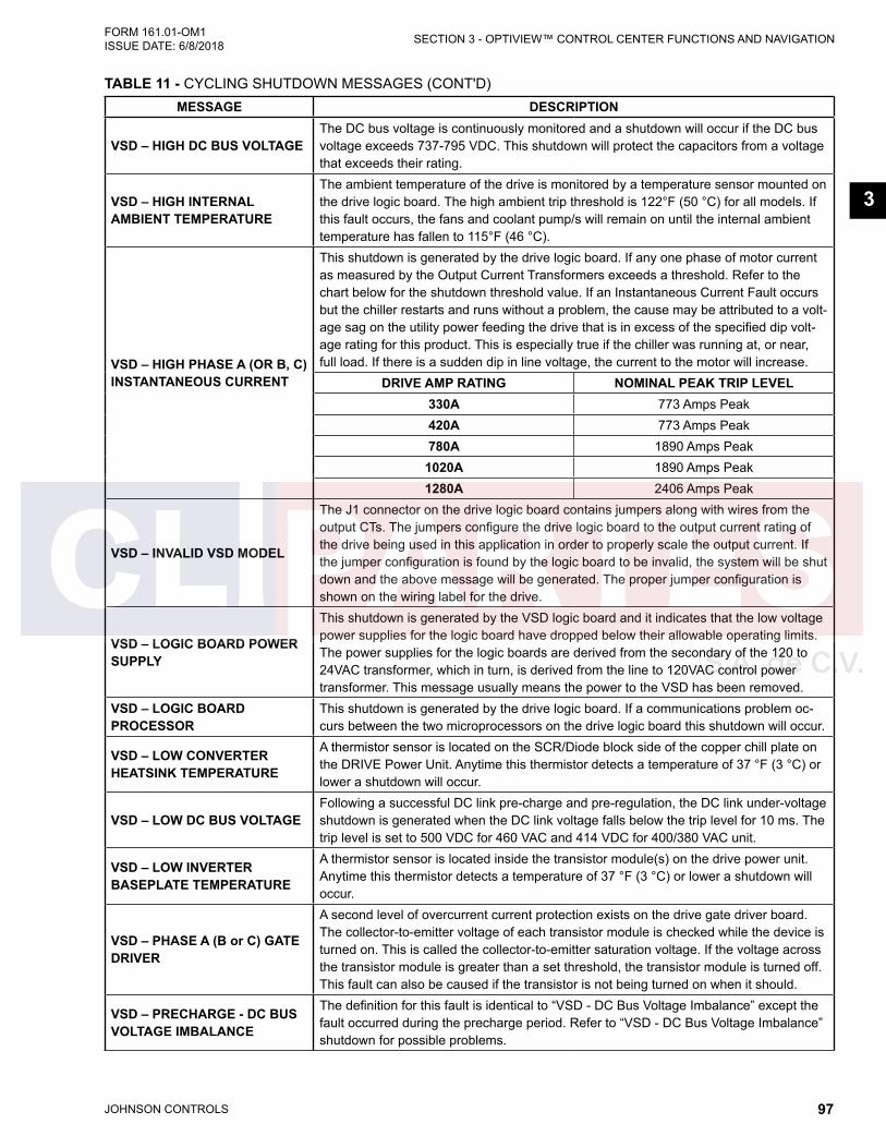
JOHNSON CONTROLS 97
SECTION 3 - OPTIVIEW™ CONTROL CENTER FUNCTIONS AND NAVIGATIONFORM 161.01-OM1 ISSUE DATE: 6/8/2018
3
MESSAGE DESCRIPTION
VSD – HIGH DC BUS VOLTAGEThe DC bus voltage is continuously monitored and a shutdown will occur if the DC bus voltage exceeds 737-795 VDC. This shutdown will protect the capacitors from a voltage that exceeds their rating.
VSD – HIGH INTERNAL AMBIENT TEMPERATURE
The ambient temperature of the drive is monitored by a temperature sensor mounted on the drive logic board. The high ambient trip threshold is 122°F (50 °C) for all models. If this fault occurs, the fans and coolant pump/s will remain on until the internal ambient temperature has fallen to 115°F (46 °C).
VSD – HIGH PHASE A (OR B, C)INSTANTANEOUS CURRENT
This shutdown is generated by the drive logic board. If any one phase of motor current as measured by the Output Current Transformers exceeds a threshold. Refer to the chart below for the shutdown threshold value. If an Instantaneous Current Fault occurs but the chiller restarts and runs without a problem, the cause may be attributed to a volt-age sag on the utility power feeding the drive that is in excess of the specified dip volt-age rating for this product. This is especially true if the chiller was running at, or near, full load. If there is a sudden dip in line voltage, the current to the motor will increase.
DRIVE AMP RATING NOMINAL PEAK TRIP LEVEL330A 773 Amps Peak420A 773 Amps Peak780A 1890 Amps Peak1020A 1890 Amps Peak1280A 2406 Amps Peak
VSD – INVALID VSD MODEL
The J1 connector on the drive logic board contains jumpers along with wires from the output CTs. The jumpers configure the drive logic board to the output current rating of the drive being used in this application in order to properly scale the output current. If the jumper configuration is found by the logic board to be invalid, the system will be shut down and the above message will be generated. The proper jumper configuration is shown on the wiring label for the drive.
VSD – LOGIC BOARD POWER SUPPLY
This shutdown is generated by the VSD logic board and it indicates that the low voltage power supplies for the logic board have dropped below their allowable operating limits. The power supplies for the logic boards are derived from the secondary of the 120 to 24VAC transformer, which in turn, is derived from the line to 120VAC control power transformer. This message usually means the power to the VSD has been removed.
VSD – LOGIC BOARD PROCESSOR
This shutdown is generated by the drive logic board. If a communications problem oc-curs between the two microprocessors on the drive logic board this shutdown will occur.
VSD – LOW CONVERTER HEATSINK TEMPERATURE
A thermistor sensor is located on the SCR/Diode block side of the copper chill plate on the DRIVE Power Unit. Anytime this thermistor detects a temperature of 37 °F (3 °C) or lower a shutdown will occur.
VSD – LOW DC BUS VOLTAGEFollowing a successful DC link pre-charge and pre-regulation, the DC link under-voltage shutdown is generated when the DC link voltage falls below the trip level for 10 ms. The trip level is set to 500 VDC for 460 VAC and 414 VDC for 400/380 VAC unit.
VSD – LOW INVERTER BASEPLATE TEMPERATURE
A thermistor sensor is located inside the transistor module(s) on the drive power unit. Anytime this thermistor detects a temperature of 37 °F (3 °C) or lower a shutdown will occur.
VSD – PHASE A (B or C) GATE DRIVER
A second level of overcurrent current protection exists on the drive gate driver board. The collector-to-emitter voltage of each transistor module is checked while the device is turned on. This is called the collector-to-emitter saturation voltage. If the voltage across the transistor module is greater than a set threshold, the transistor module is turned off. This fault can also be caused if the transistor is not being turned on when it should.
VSD – PRECHARGE - DC BUS VOLTAGE IMBALANCE
The definition for this fault is identical to “VSD - DC Bus Voltage Imbalance” except the fault occurred during the precharge period. Refer to “VSD - DC Bus Voltage Imbalance” shutdown for possible problems.
TABLE 11 - CYCLING SHUTDOWN MESSAGES (CONT'D)

JOHNSON CONTROLS98
FORM 161.01-OM1 ISSUE DATE: 6/8/2018SECTION 3 - OPTIVIEW™ CONTROL CENTER FUNCTIONS AND NAVIGATION
MESSAGE DESCRIPTION
VSD – PRECHARGE – LOW DC BUS VOLTAGE 1
During Pre-charge, the dc-link voltage must reach at least low threshold which is determined by Line Voltage Setpoint (see the table below) within 4 seconds after the pre-charge signal has been commanded. If this condition is not met, this shutdown is generated. The VSD logic board shall time 10 seconds before clearing the fault and allowing another pre-charge to start. The VSD’s fan(s) and water pump(s) shall remain energized during this time. The VSD logic board shall allow up to three consecutive pre-charge-related faults to occur. After the third consecutive pre-charge-related fault, Safety Shutdown message “VSD – PRECHARGE LOCKOUT” is generated.
LINE VOLTAGE LOW THRESHOLD (VOLTS)380/400/415 41
460 50
VSD – PRECHARGE – LOW DC BUS VOLTAGE 2
During Pre-charge, the DC-link voltage must reach at least high threshold which is determined by Line Voltage Setpoint (see the table below) within 20 seconds after the pre-charge signal has been commanded. If this condition is not met, this shutdown is generated. The VSD logic board shall time 10 seconds before clearing the fault and allowing another pre-charge to start. The VSD’s fan(s) and water pump(s) shall remain energized during this time. The VSD logic board shall allow up to three consecutive pre-charge-related faults to occur. After the third consecutive pre-charge-related fault, Safety Shutdown message “VSD – PRECHARGE LOCKOUT” is generated.
LINE VOLTAGE LOW THRESHOLD (VOLTS)380/400/415 414
460 500
VSD – RUN SIGNAL
Redundant RUN signals are generated by the control center; one via TB6-24 and the second via the Serial Communications link. If both run commands are not received by the VSD Logic Board within 5 seconds, a shutdown is performed and this message is displayed. This is generally indicative of a wiring problem between the control center and the VSD.
VSD – SERIAL RECEIVE
This message is generated when communications between the micro board and the drive logic board is disrupted for a least 22 seconds. If the optional Harmonic Filter is installed then the fault can be generated when the communications between the drive logic board and the Harmonic Filter logic board is disrupted.
VSD – SINGLE PHASE INPUT POWER
The VSD monitors the RMS value of each of the three line-to-line voltages on a cycle-by-cycle basis If the RMS value of any one of the three line-to-line voltages falls below 230 Vrms in any 1/2 cycle, this shutdown is generated.
VSD – STOP (FAULT) CONTACTS OPEN
Whenever the drive initiates a fault, it first opens the fault relay on the drive logic board. When the relay opens a message is sent to control panel's micro board, detailing the cause of the fault. If this circuit ever opens without receiving an accompanying cause for the fault over the communication link (within 11 communication tries, approximately 22 seconds) this message will be displayed. This fault may be replaced with a Serial Com-munications fault if the serial link has failed.
VSD – INVALID PWM SOFTWARE
On power up the main processor shall communicate the software type (LP, HP or production) to the PWM processor. The PWM processor shall then confirm that it has the corresponding software installed. If this condition is not met the unit shall trip on an invalid PWM software fault.
TABLE 11 - CYCLING SHUTDOWN MESSAGES (CONT'D)

JOHNSON CONTROLS 99
SECTION 3 - OPTIVIEW™ CONTROL CENTER FUNCTIONS AND NAVIGATIONFORM 161.01-OM1 ISSUE DATE: 6/8/2018
3
MESSAGE DESCRIPTION
HARMONIC FILTER – INPUT CURRENT OVERLOAD
The three phases of RMS filter current are measured by the filter DCCTs’. This informa-tion is sent to the harmonic filter logic board. If any one phase of filter current exceeds a threshold for 40 seconds a shutdown will occur. Refer to the chart below for the shut-down threshold
DRIVE CURRENT RATING NOMINAL PEAK TRIP LEVEL330/420 128 AMPS RMS
780 176 AMPS RMS1020 278 AMPS RMS1280 385 AMPS RMS
HARMONIC FILTER – DC BUS VOLTAGE IMBALANCE
The DC link is filtered by many large capacitors. These capacitors are connected in series to achieve a higher DC link voltage then can be supported by a single capacitor. It is important that the voltage is shared equally between the two sets of series capaci-tors. Each set of capacitors must share approximately 1/2 of the total DC link voltage. The harmonic filter logic board then measures the voltage of the 2 sets of the bus capacitors. If at any time while the harmonic filter is running the difference in the voltage between the 2 sets of capacitors is greater than 50 VDC then a shutdown will occur.
HARMONIC FILTER – DC CURRENT TRANSFORMER 1 (OR 2)
During initialization, with no current flowing through the direct current current transduc-ers (DCCT’s), the DCCT’s output current are measured and compared to a preset limit defined by the harmonic filter logic board. If the measured values exceed the preset limit, the DCCT’s are presumed to be bad and this shutdown will be generated.
HARMONIC FILTER – HIGH DC BUS VOLTAGE
The harmonic filter logic board continuously monitors the harmonic filter DC bus volt-age. If the level of the DC bus voltage exceeds a range of 822 to 900 VDC this shut-down is initiated. Keep in mind that the harmonic filter has its own DC bus as part of the harmonic filter power unit. The harmonic filter DC bus is not connected in any way with the drive’s DC bus.
HARMONIC FILTER – HIGH PHASE A (OR B, C) CURRENT
The output current of the harmonic filter is read by the Direct Current-Current Trans-ducer (DCCT). This current information is sent to the harmonic filter logic board where it is compared against a threshold. If the output current of the harmonic filter power unit is greater than the threshold..
DRIVE CURRENT RATING NOMINAL PEAK TRIP LEVEL330 270 ± 25 AMPS Pk420 378 ± 59 AMPS Pk780 523 ± 84 AMPS Pk
1020 782 ± 118 AMPS Pk1280 1274 ± 104 AMPS Pk
HARMONIC FILTER – LOGIC BOARD OR COMMUNICATIONS
This shutdown states the hardware on the harmonic filter logic board is indicating a fault, but the software on the harmonic filter logic board does not state why. The harmonic filter logic board signals a fault condition to the drive logic board but does not respond to a software request for fault information.
HARMONIC FILTER – LOGIC BOARD POWER SUPPLY
This shutdown indicates one of the low voltage power supplies on the harmonic filter logic board have dropped below their permissible operating voltage range. The harmon-ic filter logic board receives its power from the drive logic board. The power supplies for the drive logic board are in turn derived from the secondary of the 120 to 24 VAC trans-former. This fault is typical when control power to the board is removed and reapplied.
TABLE 11 - CYCLING SHUTDOWN MESSAGES (CONT'D)
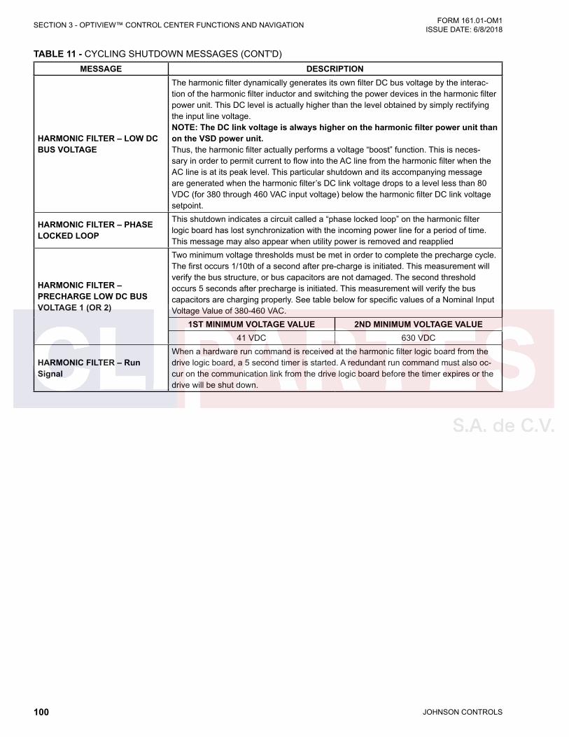
JOHNSON CONTROLS100
FORM 161.01-OM1 ISSUE DATE: 6/8/2018SECTION 3 - OPTIVIEW™ CONTROL CENTER FUNCTIONS AND NAVIGATION
TABLE 11 - CYCLING SHUTDOWN MESSAGES (CONT'D)MESSAGE DESCRIPTION
HARMONIC FILTER – LOW DC BUS VOLTAGE
The harmonic filter dynamically generates its own filter DC bus voltage by the interac-tion of the harmonic filter inductor and switching the power devices in the harmonic filter power unit. This DC level is actually higher than the level obtained by simply rectifying the input line voltage.NOTE: The DC link voltage is always higher on the harmonic filter power unit than on the VSD power unit.Thus, the harmonic filter actually performs a voltage “boost” function. This is neces-sary in order to permit current to flow into the AC line from the harmonic filter when the AC line is at its peak level. This particular shutdown and its accompanying message are generated when the harmonic filter’s DC link voltage drops to a level less than 80 VDC (for 380 through 460 VAC input voltage) below the harmonic filter DC link voltage setpoint.
HARMONIC FILTER – PHASE LOCKED LOOP
This shutdown indicates a circuit called a “phase locked loop” on the harmonic filter logic board has lost synchronization with the incoming power line for a period of time. This message may also appear when utility power is removed and reapplied
HARMONIC FILTER – PRECHARGE LOW DC BUS VOLTAGE 1 (OR 2)
Two minimum voltage thresholds must be met in order to complete the precharge cycle. The first occurs 1/10th of a second after pre-charge is initiated. This measurement will verify the bus structure, or bus capacitors are not damaged. The second threshold occurs 5 seconds after precharge is initiated. This measurement will verify the bus capacitors are charging properly. See table below for specific values of a Nominal Input Voltage Value of 380-460 VAC.
1ST MINIMUM VOLTAGE VALUE 2ND MINIMUM VOLTAGE VALUE41 VDC 630 VDC
HARMONIC FILTER – Run Signal
When a hardware run command is received at the harmonic filter logic board from the drive logic board, a 5 second timer is started. A redundant run command must also oc-cur on the communication link from the drive logic board before the timer expires or the drive will be shut down.
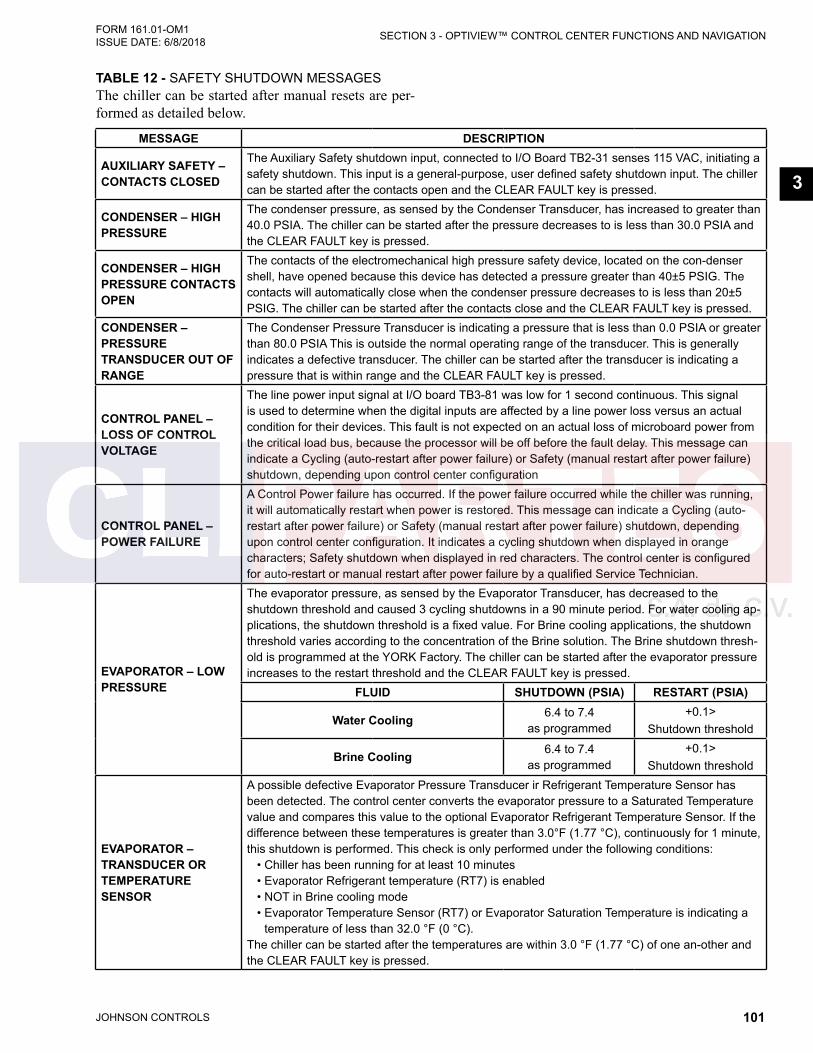
JOHNSON CONTROLS 101
SECTION 3 - OPTIVIEW™ CONTROL CENTER FUNCTIONS AND NAVIGATIONFORM 161.01-OM1 ISSUE DATE: 6/8/2018
3
MESSAGE DESCRIPTION
AUXILIARY SAFETY – CONTACTS CLOSED
The Auxiliary Safety shutdown input, connected to I/O Board TB2-31 senses 115 VAC, initiating a safety shutdown. This input is a general-purpose, user defined safety shutdown input. The chiller can be started after the contacts open and the CLEAR FAULT key is pressed.
CONDENSER – HIGH PRESSURE
The condenser pressure, as sensed by the Condenser Transducer, has increased to greater than 40.0 PSIA. The chiller can be started after the pressure decreases to is less than 30.0 PSIA and the CLEAR FAULT key is pressed.
CONDENSER – HIGH PRESSURE CONTACTS OPEN
The contacts of the electromechanical high pressure safety device, located on the con-denser shell, have opened because this device has detected a pressure greater than 40±5 PSIG. The contacts will automatically close when the condenser pressure decreases to is less than 20±5 PSIG. The chiller can be started after the contacts close and the CLEAR FAULT key is pressed.
CONDENSER – PRESSURE TRANSDUCER OUT OF RANGE
The Condenser Pressure Transducer is indicating a pressure that is less than 0.0 PSIA or greater than 80.0 PSIA This is outside the normal operating range of the transducer. This is generally indicates a defective transducer. The chiller can be started after the transducer is indicating a pressure that is within range and the CLEAR FAULT key is pressed.
CONTROL PANEL – LOSS OF CONTROL VOLTAGE
The line power input signal at I/O board TB3-81 was low for 1 second continuous. This signal is used to determine when the digital inputs are affected by a line power loss versus an actual condition for their devices. This fault is not expected on an actual loss of microboard power from the critical load bus, because the processor will be off before the fault delay. This message can indicate a Cycling (auto-restart after power failure) or Safety (manual restart after power failure) shutdown, depending upon control center configuration
CONTROL PANEL – POWER FAILURE
A Control Power failure has occurred. If the power failure occurred while the chiller was running, it will automatically restart when power is restored. This message can indicate a Cycling (auto-restart after power failure) or Safety (manual restart after power failure) shutdown, depending upon control center configuration. It indicates a cycling shutdown when displayed in orange characters; Safety shutdown when displayed in red characters. The control center is configured for auto-restart or manual restart after power failure by a qualified Service Technician.
EVAPORATOR – LOW PRESSURE
The evaporator pressure, as sensed by the Evaporator Transducer, has decreased to the shutdown threshold and caused 3 cycling shutdowns in a 90 minute period. For water cooling ap-plications, the shutdown threshold is a fixed value. For Brine cooling applications, the shutdown threshold varies according to the concentration of the Brine solution. The Brine shutdown thresh-old is programmed at the YORK Factory. The chiller can be started after the evaporator pressure increases to the restart threshold and the CLEAR FAULT key is pressed.
FLUID SHUTDOWN (PSIA) RESTART (PSIA)
Water Cooling 6.4 to 7.4 as programmed
+0.1>Shutdown threshold
Brine Cooling 6.4 to 7.4 as programmed
+0.1>Shutdown threshold
EVAPORATOR – TRANSDUCER OR TEMPERATURE SENSOR
A possible defective Evaporator Pressure Transducer ir Refrigerant Temperature Sensor has been detected. The control center converts the evaporator pressure to a Saturated Temperature value and compares this value to the optional Evaporator Refrigerant Temperature Sensor. If the difference between these temperatures is greater than 3.0°F (1.77 °C), continuously for 1 minute, this shutdown is performed. This check is only performed under the following conditions: • Chiller has been running for at least 10 minutes • Evaporator Refrigerant temperature (RT7) is enabled • NOT in Brine cooling mode • Evaporator Temperature Sensor (RT7) or Evaporator Saturation Temperature is indicating a
temperature of less than 32.0 °F (0 °C).The chiller can be started after the temperatures are within 3.0 °F (1.77 °C) of one an-other and the CLEAR FAULT key is pressed.
TABLE 12 - SAFETY SHUTDOWN MESSAGESThe chiller can be started after manual resets are per-formed as detailed below.
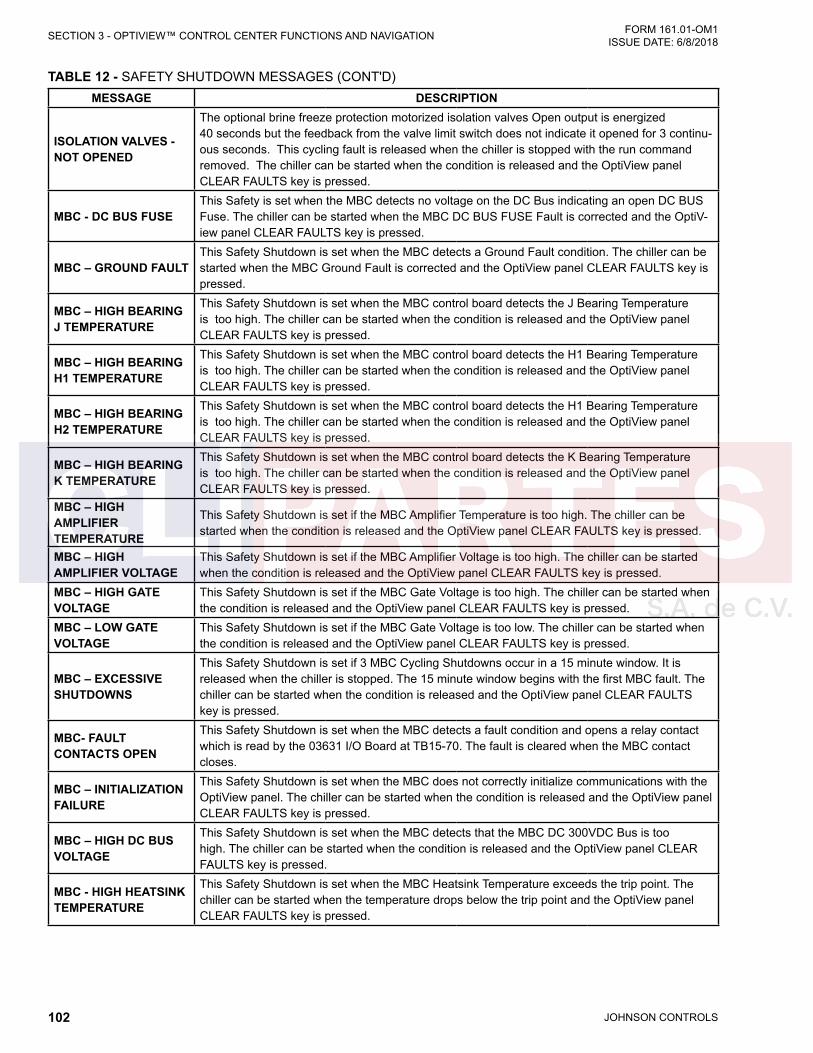
JOHNSON CONTROLS102
FORM 161.01-OM1 ISSUE DATE: 6/8/2018SECTION 3 - OPTIVIEW™ CONTROL CENTER FUNCTIONS AND NAVIGATION
MESSAGE DESCRIPTION
ISOLATION VALVES - NOT OPENED
The optional brine freeze protection motorized isolation valves Open output is energized40 seconds but the feedback from the valve limit switch does not indicate it opened for 3 continu-ous seconds. This cycling fault is released when the chiller is stopped with the run command removed. The chiller can be started when the condition is released and the OptiView panel CLEAR FAULTS key is pressed.
MBC - DC BUS FUSEThis Safety is set when the MBC detects no voltage on the DC Bus indicating an open DC BUS Fuse. The chiller can be started when the MBC DC BUS FUSE Fault is corrected and the OptiV-iew panel CLEAR FAULTS key is pressed.
MBC – GROUND FAULTThis Safety Shutdown is set when the MBC detects a Ground Fault condition. The chiller can be started when the MBC Ground Fault is corrected and the OptiView panel CLEAR FAULTS key is pressed.
MBC – HIGH BEARING J TEMPERATURE
This Safety Shutdown is set when the MBC control board detects the J Bearing Temperature is too high. The chiller can be started when the condition is released and the OptiView panel CLEAR FAULTS key is pressed.
MBC – HIGH BEARING H1 TEMPERATURE
This Safety Shutdown is set when the MBC control board detects the H1 Bearing Temperature is too high. The chiller can be started when the condition is released and the OptiView panel CLEAR FAULTS key is pressed.
MBC – HIGH BEARING H2 TEMPERATURE
This Safety Shutdown is set when the MBC control board detects the H1 Bearing Temperature is too high. The chiller can be started when the condition is released and the OptiView panel CLEAR FAULTS key is pressed.
MBC – HIGH BEARING K TEMPERATURE
This Safety Shutdown is set when the MBC control board detects the K Bearing Temperature is too high. The chiller can be started when the condition is released and the OptiView panel CLEAR FAULTS key is pressed.
MBC – HIGH AMPLIFIER TEMPERATURE
This Safety Shutdown is set if the MBC Amplifier Temperature is too high. The chiller can be started when the condition is released and the OptiView panel CLEAR FAULTS key is pressed.
MBC – HIGH AMPLIFIER VOLTAGE
This Safety Shutdown is set if the MBC Amplifier Voltage is too high. The chiller can be started when the condition is released and the OptiView panel CLEAR FAULTS key is pressed.
MBC – HIGH GATE VOLTAGE
This Safety Shutdown is set if the MBC Gate Voltage is too high. The chiller can be started when the condition is released and the OptiView panel CLEAR FAULTS key is pressed.
MBC – LOW GATE VOLTAGE
This Safety Shutdown is set if the MBC Gate Voltage is too low. The chiller can be started when the condition is released and the OptiView panel CLEAR FAULTS key is pressed.
MBC – EXCESSIVE SHUTDOWNS
This Safety Shutdown is set if 3 MBC Cycling Shutdowns occur in a 15 minute window. It is released when the chiller is stopped. The 15 minute window begins with the first MBC fault. The chiller can be started when the condition is released and the OptiView panel CLEAR FAULTS key is pressed.
MBC- FAULT CONTACTS OPEN
This Safety Shutdown is set when the MBC detects a fault condition and opens a relay contact which is read by the 03631 I/O Board at TB15-70. The fault is cleared when the MBC contact closes.
MBC – INITIALIZATION FAILURE
This Safety Shutdown is set when the MBC does not correctly initialize communications with the OptiView panel. The chiller can be started when the condition is released and the OptiView panel CLEAR FAULTS key is pressed.
MBC – HIGH DC BUS VOLTAGE
This Safety Shutdown is set when the MBC detects that the MBC DC 300VDC Bus is too high. The chiller can be started when the condition is released and the OptiView panel CLEAR FAULTS key is pressed.
MBC - HIGH HEATSINK TEMPERATURE
This Safety Shutdown is set when the MBC Heatsink Temperature exceeds the trip point. The chiller can be started when the temperature drops below the trip point and the OptiView panel CLEAR FAULTS key is pressed.
TABLE 12 - SAFETY SHUTDOWN MESSAGES (CONT'D)

JOHNSON CONTROLS 103
SECTION 3 - OPTIVIEW™ CONTROL CENTER FUNCTIONS AND NAVIGATIONFORM 161.01-OM1 ISSUE DATE: 6/8/2018
3
MESSAGE DESCRIPTION
MBC – NOT LEVITATED
This Safety Shutdown is set when OptiView software is commanding MBC Levitation Mode ON but the MBC is not reporting Levitated within 15 seconds. This fault is prohibited when the MBC Alive input is not high, indicating the MBC unavailable. This fault is released when the chiller is stopped. The chiller can be started when the condition is released and the OptiView panel CLEAR FAULTS key is pressed.
MBC – OVERSPEED FAULT
This Safety Shutdown is set when the MBC determines the rotor speed exceeds the pro-grammed setpoint for 0.1 seconds continuous. Rotor speed is transmitted to the MBC from the VSD. The MBC Fault contacts open. The MBC remains in Levitation mode with the motor shaft levitated until commanded to de-levitate over serial comms. This shutdown is released when the speed signal no longer exceeds the setpoint, which should occur when the chiller is stopped. The chiller can be started when the condition is released and the OptiView panel CLEAR FAULTS key is pressed.
MBC - POWER SUPPLY FAULT
This Safety Shutdown is set when any of the MBC power supplies drops below their low limit. This fault could be caused by a faulty MBC power supply or faulty wiring. The chiller can be started when the condition is released and the OptiView panel CLEAR FAULTS key is pressed.
MBC - POWER FAIL LANDING
This Safety Shutdown is set when the panel boots up after a power loss has occurred and the buffer data prior to the shutdown showed motor speed > 0, indicating the motor was rotating when the UPS power was lost. If the Power Fail Landing Counter on the MBC Details Screen is < 3, the chiller can be restarted after the cause of a loss of UPS power is determined and remedied and the OptiView panel CLEAR FAULTS key is pressed. IF the Power Fail Landing Counter is => 3, lockout occurs and must be reset by a Service Technician.
MBC – SPEED SIGNAL FAULT
This Safety Shutdown is set when the MBC has the speed signal cycling fault three times in a 90-minute window. The window is started when not currently in a window and a MBC Speed Sig-nal cycling fault is received. The MBC Fault contacts open. The MBC remains in Levitation mode with the motor shaft levitated until commanded to de-levitate over serial comms. This shutdown is released when a valid speed signal over 10 Hz is presented or the MBC is not in Rotation mode. The chiller can be started when the condition is released and the OptiView panel CLEAR FAULTS key is pressed.
MBC – WATCHDOG
This Safety Shutdown is set when the MBC microboard program does not reset the watchdog timer. This fault could be caused by a faulty MBC program load or a failed MBC microboard. The chiller can be started when the condition is released and the OptiView panel CLEAR FAULTS key is pressed.
SAFETY STOP
This is set when the panel safety stop hardware push button is depressed, removing in-put from the I/O Board terminal TB13-28 for > 500msec. continuous. It also sets the local command to STOP. The chiller can be started when the push button is released and the OptiView panel CLEAR FAULTS key is pressed.
MOTOR – HIGH WIND-ING TEMPERATURE
This safety shutdown occurs when any of the enabled motor winding temperatures exceeded the programmed High Winding Temperature Shutdown Threshold of 270˚F (132.2˚C) for 3 continu-ous seconds. The chiller can be started after all winding temperatures decreased to at least 18˚F (10˚C) below the shutdown threshold and the COMPRESSOR is stopped. The safety shutdown will not act on any individual winding temperature sensor that has been disabled with the TEMPERATURE DIS-ABLE Setpoint on the Motor Details Screen.
MOTOR – HIGH HOUSING TEMPERATURE
This Safety Shutdown is set when Motor Housing Temperature is greater than or equal to 185 °F (85 °C). This fault is released when Motor Housing Temperature is less than 185 °F (85 °C). The chiller can be started when the condition is released and the OptiView panel CLEAR FAULTS key is pressed.
MOTOR – LOW WINDING TEMPERATURE
This Safety Shutdown is set when any enabled Motor Winding Temperature is less than 32.1°F (0.05°C). This fault is released when the windings are greater than 32.1°F (0.05 °C).
TABLE 12 - SAFETY SHUTDOWN MESSAGES (CONT'D)
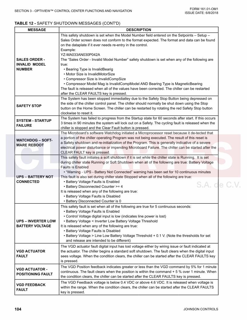
JOHNSON CONTROLS104
FORM 161.01-OM1 ISSUE DATE: 6/8/2018SECTION 3 - OPTIVIEW™ CONTROL CENTER FUNCTIONS AND NAVIGATION
MESSAGE DESCRIPTION
SALES ORDER - INVALID MODEL NUMBER
This safety shutdown is set when the Model Number field entered on the Setpoints – Setup –Sales Order screen does not conform to the format expected. The format and data can be found on the dataplate if it ever needs re-entry in the control.Example: YZ-MA033AN030P042AThe “Sales Order - Invalid Model Number” safety shutdown is set when any of the following are true: • Bearing Type is InvalidBearig • Motor Size is InvalidMotorSize • Compressor Size is InvalidCompSize • Compressor Model Mag is InvalidCompModel AND Bearing Type is MagneticBearingThe fault is released when all of the values have been corrected. The chiller can be restarted after the CLEAR FAULTS key is pressed.
SAFETY STOP
The System has been stopped immediatley due to the Safety Stop Button being depressed on the side of the chiller control panel. The chiller should normally be shut down using the Stop button on the Home Screen. The chiller can be restarted by rotating the red Safety Stop button clockwise to reset it.
SYSTEM - STARTUP FAILURE
The System has failed to progress from the Startup state for 60 seconds after start. If this occurs 3 times in 90 minutes the system will lock out on a Safety. The cycling fault is released when the chiller is stopped and the Clear Fault button is pressed.
WATCHDOG – SOFT-WARE REBOOT
The Microboard’s software Watchdog initiated a Microprocessor reset because it de-tected that a portion of the chiller operating Program was not being executed. The result of this reset is a Safety shutdown and re-initialization of the Program. This is generally indicative of a severe electrical power disturbance or impending Microboard Failure. The chiller can be started after the CLEAR FAULT key is pressed.
UPS – BATTERY NOT CONNECTED
This safety fault initiates a soft shutdown if it is set while the chiller state is Running. It is set during chiller state Running or Soft Shutdown when all of the following are true: Battery Voltage Faults is Enabled • “Warning - UPS - Battery Not Connected” warning has been set for 10 continuous minutesThis fault is also set during chiller state Stopped when all of the following are true: • Battery Voltage Faults is Enabled • Battery Disconnected Counter >= 4It is released when any of the following are true: • Battery Voltage Faults is Disabled • Battery Disconnected Counter is 0
UPS – INVERTER LOW BATTERY VOLTAGE
This safety fault is set when all of the following are true for 5 continuous seconds: • Battery Voltage Faults is Enabled • Control Voltage digital input is low (indicates line power is lost) • Battery Voltage < Inverter Low Battery Voltage ThresholdIt is released when any of the following are true: • Battery Voltage Faults is Disabled • Battery Voltage > Line Low Battery Voltage Threshold + 0.1 V. (Note the thresholds for set
and release are intended to be different)
VGD ACTUATOR FAULT
The VGD actuator fault digital input has lost voltage either by wiring issue or fault indicated at the actuator. The chiller begins a standard soft shutdown. The fault clears when the digital input sees voltage. When the condition clears, the chiller can be started after the CLEAR FAULTS key is pressed.
VGD ACTUATOR - POSITIONING FAULT
The VGD Position feedback indicates greater or less than the VGD command by 5% for 1 minute continuous. The fault clears when the position is within the command + 5 % over 1 minute. When the condition clears, the chiller can be started after the CLEAR FAULTS key is pressed.
VGD FEEDBACK FAULT
The VGD Feedback voltage is below 0.4 VDC or above 4.6 VDC. It is released when voltage is within the range. When the condition clears, the chiller can be started after the CLEAR FAULTS key is pressed.
TABLE 12 - SAFETY SHUTDOWN MESSAGES (CONT'D)
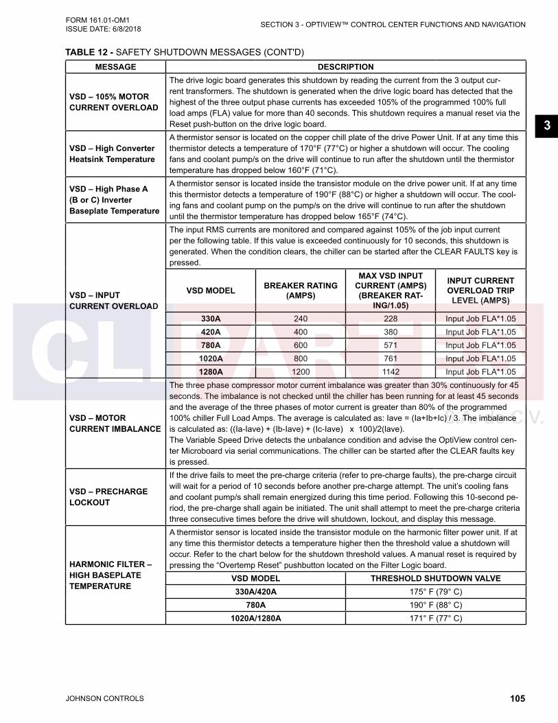
JOHNSON CONTROLS 105
SECTION 3 - OPTIVIEW™ CONTROL CENTER FUNCTIONS AND NAVIGATIONFORM 161.01-OM1 ISSUE DATE: 6/8/2018
3
MESSAGE DESCRIPTION
VSD – 105% MOTOR CURRENT OVERLOAD
The drive logic board generates this shutdown by reading the current from the 3 output cur-rent transformers. The shutdown is generated when the drive logic board has detected that the highest of the three output phase currents has exceeded 105% of the programmed 100% full load amps (FLA) value for more than 40 seconds. This shutdown requires a manual reset via the Reset push-button on the drive logic board.
VSD – High Converter Heatsink Temperature
A thermistor sensor is located on the copper chill plate of the drive Power Unit. If at any time this thermistor detects a temperature of 170°F (77°C) or higher a shutdown will occur. The cooling fans and coolant pump/s on the drive will continue to run after the shutdown until the thermistor temperature has dropped below 160°F (71°C).
VSD – High Phase A (B or C) Inverter Baseplate Temperature
A thermistor sensor is located inside the transistor module on the drive power unit. If at any time this thermistor detects a temperature of 190°F (88°C) or higher a shutdown will occur. The cool-ing fans and coolant pump on the pump/s on the drive will continue to run after the shutdown until the thermistor temperature has dropped below 165°F (74°C).
VSD – INPUT CURRENT OVERLOAD
The input RMS currents are monitored and compared against 105% of the job input current per the following table. If this value is exceeded continuously for 10 seconds, this shutdown is generated. When the condition clears, the chiller can be started after the CLEAR FAULTS key is pressed.
VSD MODEL BREAKER RATING (AMPS)
MAX VSD INPUT CURRENT (AMPS) (BREAKER RAT-
ING/1.05)
INPUT CURRENT OVERLOAD TRIP
LEVEL (AMPS)
330A 240 228 Input Job FLA*1.05420A 400 380 Input Job FLA*1.05780A 600 571 Input Job FLA*1.05
1020A 800 761 Input Job FLA*1.051280A 1200 1142 Input Job FLA*1.05
VSD – MOTOR CURRENT IMBALANCE
The three phase compressor motor current imbalance was greater than 30% continuously for 45 seconds. The imbalance is not checked until the chiller has been running for at least 45 seconds and the average of the three phases of motor current is greater than 80% of the programmed 100% chiller Full Load Amps. The average is calculated as: Iave = (Ia+Ib+Ic) / 3. The imbalance is calculated as: ((Ia-Iave) + (Ib-Iave) + (Ic-Iave) x 100)/2(lave).The Variable Speed Drive detects the unbalance condition and advise the OptiView control cen-ter Microboard via serial communications. The chiller can be started after the CLEAR faults key is pressed.
VSD – PRECHARGE LOCKOUT
If the drive fails to meet the pre-charge criteria (refer to pre-charge faults), the pre-charge circuit will wait for a period of 10 seconds before another pre-charge attempt. The unit’s cooling fans and coolant pump/s shall remain energized during this time period. Following this 10-second pe-riod, the pre-charge shall again be initiated. The unit shall attempt to meet the pre-charge criteria three consecutive times before the drive will shutdown, lockout, and display this message.
HARMONIC FILTER – HIGH BASEPLATE TEMPERATURE
A thermistor sensor is located inside the transistor module on the harmonic filter power unit. If at any time this thermistor detects a temperature higher then the threshold value a shutdown will occur. Refer to the chart below for the shutdown threshold values. A manual reset is required by pressing the “Overtemp Reset” pushbutton located on the Filter Logic board.
VSD MODEL THRESHOLD SHUTDOWN VALVE330A/420A 175° F (79° C)
780A 190° F (88° C)1020A/1280A 171° F (77° C)
TABLE 12 - SAFETY SHUTDOWN MESSAGES (CONT'D)

JOHNSON CONTROLS106
FORM 161.01-OM1 ISSUE DATE: 6/8/2018SECTION 3 - OPTIVIEW™ CONTROL CENTER FUNCTIONS AND NAVIGATION
MESSAGE DESCRIPTION
Harmonic Filter – High Total Demand Distortion
The control center determines this shutdown by using data supplied from the harmonic filter logic board. This shutdown indicates that the filter is not operating correctly or the input current to the drive/filter system is not sinusoidal. This shutdown will occur if the Total Demand Distortion (TDD) in any one phase exceeds 25% continuously for 45 seconds. TDD is an acronym for Total Demand Distortion, a term defined by the IEEE Std 519-1992 standard as “the total root - sum - square harmonic current distortion, in percent of the maximum demand load current (15 or 30 min demand)”. .
TABLE 12 - SAFETY SHUTDOWN MESSAGES (CONT'D)

JOHNSON CONTROLS 107
FORM 161.01-OM1 ISSUE DATE: 6/8/2018
4
SECTION 4 - VSD OPERATION
PYT MODEL VSD OVERVIEWThe YORK PYT model VSD is a liquid cooled, transis-torized, PWM inverter in a highly integrated package mounted directly to the chiller. This VSD is specifi-cally designed to drive the high speed induction motor with magnetic bearings used on the YORK model YZ Centrifugal Liquid Chiller. This allows the chiller to be designed as a complete system, and take full advantage of the strengths of each major component within the system.
The PYT drive enclosure contains lethal AC and DC voltages. Only suitably trained and qualified personnel are permitted to open the VSD enclosure for service.
• NEVER place loose tools, debris or any objects inside the PYT drive enclosure.
• NEVER allow the PYT drive enclosure doors to remain open. Keep the doors closed and ensure all latches are en-gaged on each door unless the unit is being serviced.
• ALWAYS lockout the disconnect sup-plying AC to the chiller when servicing the VSD.
• DO NOT switch on the circuit breaker if a VSD door remains open.
The power section of the VSD is composed of four ma-jor blocks:
• The AC to DC rectifier section
• The DC bus filter section
• The three phase DC to AC inverter section
• The output suppression network
PYT MODEL VSD COMPONENTSAt the input of the VSD, an electronic circuit breaker with ground fault sensing connects the AC line to an AC line inductor and then to the DC converter. The line inductor will limit the amount of fault current so that the electronic circuit breaker is sufficient for pro-tecting the VSD. The following description of opera-tion is specific for the 330 amp VSD unless otherwise noted. See Figure 38 on page 110 through Figure 47 on page 117 for component locations in each PYT model cabinet.
AC to DC RectifierThe AC to DC converter uses 3 Silicon Controlled Rectifiers (SCR’s) and 3 diodes. One SCR and one di-ode are contained in each module. Three modules are required to converter the 3 phase input AC voltage into DC voltage. The SCRs are mounted on the bottom of the liquid cooled heat sink. The use of the SCR’s in the converter permits pre-charge of the DC bus capaci-tors when the chiller enters the prelube cycle; it also provides a fast disconnect from the AC line when the chiller enters the coastdown cycle. During a coastdown cycle, the SCR’s in the converter are no longer turned on and remain in a turned off condition until the next pre-charge cycle and the DC bus capacitors will start to discharge through the bleeder resistors.
When the chiller enters the prelube cycle, the VSD is commanded to pre-charge and the SCR’s are gradually turned on to slowly charge the DC bus capacitors. This is called the pre-charge period, which last for 20 sec-onds. At this time the SCR’s are fully turned on. The VSD logic board provides the command to the SCR trigger board to pre-charge and the SCR trigger board provides the turn on commands for the SCR’s.
Although many of these parts are similar to the parts used in previous VSD designs, these parts are only compatible with VSDs having the base part numbers. Failure to use the correct parts may cause major damage to these and other components in the VSD.
DC Bus FilterThe DC link section of the VSD consists of a series of electrolytic capacitors. The capacitors provide a large energy reservoir for use by the DC to AC inverter sec-tion of the VSD and serve to filter voltage ripple on the DC bus. The capacitors are contained in the VSD power unit. “Bleeder” resistors are mounted on the side of the power unit to provide a discharge path for the stored energy in the capacitors in the off cycle, and to allow for balanced charging of the capacitor banks dur-ing operation.
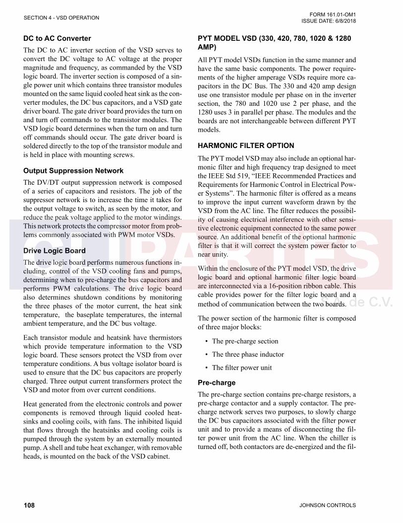
JOHNSON CONTROLS108
FORM 161.01-OM1 ISSUE DATE: 6/8/2018SECTION 4 - VSD OPERATION
DC to AC ConverterThe DC to AC inverter section of the VSD serves to convert the DC voltage to AC voltage at the proper magnitude and frequency, as commanded by the VSD logic board. The inverter section is composed of a sin-gle power unit which contains three transistor modules mounted on the same liquid cooled heat sink as the con-verter modules, the DC bus capacitors, and a VSD gate driver board. The gate driver board provides the turn on and turn off commands to the transistor modules. The VSD logic board determines when the turn on and turn off commands should occur. The gate driver board is soldered directly to the top of the transistor module and is held in place with mounting screws.
Output Suppression NetworkThe DV/DT output suppression network is composed of a series of capacitors and resistors. The job of the suppressor network is to increase the time it takes for the output voltage to switch, as seen by the motor, and reduce the peak voltage applied to the motor windings. This network protects the compressor motor from prob-lems commonly associated with PWM motor VSDs.
Drive Logic BoardThe drive logic board performs numerous functions in-cluding, control of the VSD cooling fans and pumps, determining when to pre-charge the bus capacitors and performs PWM calculations. The drive logic board also determines shutdown conditions by monitoring the three phases of the motor current, the heat sink temperature, the baseplate temperatures, the internal ambient temperature, and the DC bus voltage.
Each transistor module and heatsink have thermistors which provide temperature information to the VSD logic board. These sensors protect the VSD from over temperature conditions. A bus voltage isolator board is used to ensure that the DC bus capacitors are properly charged. Three output current transformers protect the VSD and motor from over current conditions.
Heat generated from the electronic controls and power components is removed through liquid cooled heat-sinks and cooling coils, with fans. The inhibited liquid that flows through the heatsinks and cooling coils is pumped through the system by an externally mounted pump. A shell and tube heat exchanger, with removable heads, is mounted on the back of the VSD cabinet.
PYT MODEL VSD (330, 420, 780, 1020 & 1280 AMP)All PYT model VSDs function in the same manner and have the same basic components. The power require-ments of the higher amperage VSDs require more ca-pacitors in the DC Bus. The 330 and 420 amp design use one transistor module per phase on in the inverter section, the 780 and 1020 use 2 per phase, and the 1280 uses 3 in parallel per phase. The modules and the boards are not interchangeable between different PYT models.
HARMONIC FILTER OPTIONThe PYT model VSD may also include an optional har-monic filter and high frequency trap designed to meet the IEEE Std 519, “IEEE Recommended Practices and Requirements for Harmonic Control in Electrical Pow-er Systems”. The harmonic filter is offered as a means to improve the input current waveform drawn by the VSD from the AC line. The filter reduces the possibil-ity of causing electrical interference with other sensi-tive electronic equipment connected to the same power source. An additional benefit of the optional harmonic filter is that it will correct the system power factor to near unity.
Within the enclosure of the PYT model VSD, the drive logic board and optional harmonic filter logic board are interconnected via a 16-position ribbon cable. This cable provides power for the filter logic board and a method of communication between the two boards.
The power section of the harmonic filter is composed of three major blocks:
• The pre-charge section
• The three phase inductor
• The filter power unit
Pre-chargeThe pre-charge section contains pre-charge resistors, a pre-charge contactor and a supply contactor. The pre- charge network serves two purposes, to slowly charge the DC bus capacitors associated with the filter power unit and to provide a means of disconnecting the fil-ter power unit from the AC line. When the chiller is turned off, both contactors are de-energized and the fil-

JOHNSON CONTROLS 109
SECTION 4 - VSD OPERATIONFORM 161.01-OM1 ISSUE DATE: 6/8/2018
4
ter power unit is disconnected from the AC line. When the chiller begins to run, the pre-charge resistors are switched into the circuit via the precharge contactor for a fixed time period of 5 seconds. This permits the fil-ter capacitors in the filter power unit to slowly charge. After the 5 second time period, the supply contactor is energized and the pre-charge contactor is de-energized, permitting the filter power unit to completely charge. Three power semiconductor fuses connect the power components to the AC line and serve to help prevent rupture if a catastrophic failure occurs on the DC bus portion of the filter power unit.
Three Phase InductorThe three phase inductor provides some impedance for the filter to boost bus voltage. It effectively limits the rate of change in current at the input to the filter to a reasonable level.
Filter Power UnitThe filter power unit generates the harmonic currents required by the VSD's AC- to -DC converter so that these harmonic currents are not drawn from the AC line. The filter power unit is similar to the PYT model VSD power unit in the 330 amp VSD, except with 2 fewer capacitors in the filter capacitor “bank”, and a smaller transistor module and modified gate driver board. The harmonic filter gate driver board provides turn on and turn off commands as determined by the harmonic filter logic board. “Bleeder” resistors are mounted on the side of the filter power unit to provide a discharge path for the DC bus capacitors.
Transistor ModuleThe transistor module contains a temperature sensor that provides temperature information back to the fil-ter logic board. This sensor protects the filter transistor module from over temperature conditions. A bus isola-tor board is used to ensure that the DC bus capacitors are properly charged and that the voltage is balanced. Two output current sensors are used to protect the filter against an over current or an overload condition. Input current transformers sense the input current drawn by the VSD’s AC to DC converter. The line voltage isola-tion board provides AC line voltage information to the harmonic filter logic board, which is used to determine the proper bus voltage setpoint.
High Frequency TrapThe high frequency trap is standard on all VSD's that contain an optional harmonic filter. The high frequency trap is composed of a series of capacitors, inductors, and resistors used to reduce the effects of the PWM switching frequency of the filter inverter.
CRITICAL LOAD POWERThe VSD cabinet includes an inverter and a battery. When the source power feeding the chiller is removed, the inverter-battery combination provides an energy source to sustain control power until the motor coasts to a stop and is de-levitated. During normal operation, the inverter passes 120 VAC through a switch to power the chiller controls. This inverter is monitoring the in-coming voltage and when the source is removed, the inverter begins to provide power to the critical load cir-cuit, drawing energy from the 12V battery.
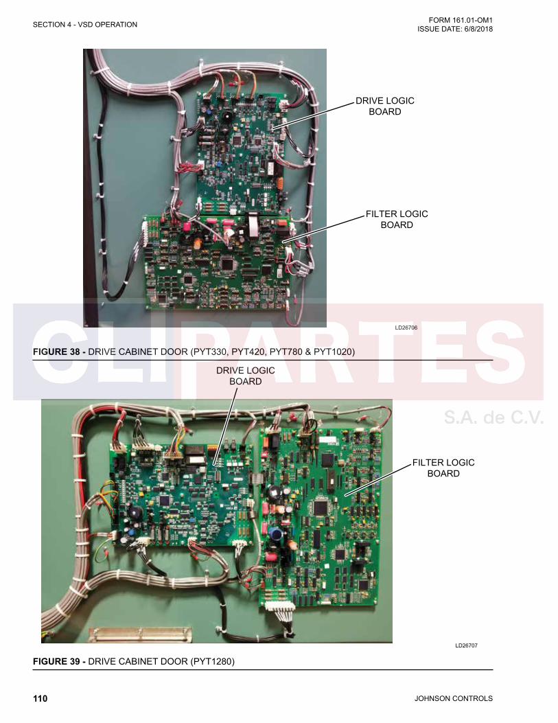
JOHNSON CONTROLS110
FORM 161.01-OM1 ISSUE DATE: 6/8/2018SECTION 4 - VSD OPERATION
LD26706
DRIVE LOGICBOARD
FILTER LOGICBOARD
FIGURE 38 - DRIVE CABINET DOOR (PYT330, PYT420, PYT780 & PYT1020)
LD26707
DRIVE LOGICBOARD
FILTER LOGICBOARD
FIGURE 39 - DRIVE CABINET DOOR (PYT1280)
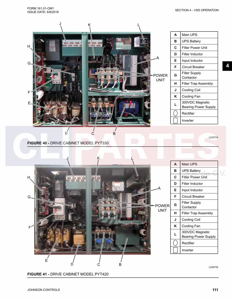
JOHNSON CONTROLS 111
SECTION 4 - VSD OPERATIONFORM 161.01-OM1 ISSUE DATE: 6/8/2018
4
LD26704
E
D C B
A
POWERUNIT
J
H
F
G
K
Inverter
L
A Main UPS
B UPS Battery
C Filter Power Unit
D Filter Inductor
E Input Inductor
F Circuit Breaker
G Filter SupplyContactor
H Filter Trap Assembly
J Cooling Coil
K Cooling Fan
L 300VDC Magnetic Bearing Power Supply
Rectifier
FIGURE 40 - DRIVE CABINET MODEL PYT330
LD26708
ED C B
A
POWERUNIT
J
H
F
G
K L
Inverter
A Main UPS
B UPS Battery
C Filter Power Unit
D Filter Inductor
E Input Inductor
F Circuit Breaker
G Filter SupplyContactor
H Filter Trap Assembly
J Cooling Coil
K Cooling Fan
L 300VDC Magnetic Bearing Power Supply
Rectifier
FIGURE 41 - DRIVE CABINET MODEL PYT420
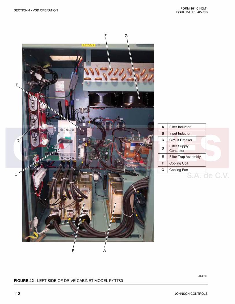
JOHNSON CONTROLS112
FORM 161.01-OM1 ISSUE DATE: 6/8/2018SECTION 4 - VSD OPERATION
LD26709
AB
C
D
E
F G
A Filter Inductor
B Input Inductor
C Circuit Breaker
D Filter SupplyContactor
E Filter Trap Assembly
F Cooling Coil
G Cooling Fan
FIGURE 42 - LEFT SIDE OF DRIVE CABINET MODEL PYT780

JOHNSON CONTROLS 113
SECTION 4 - VSD OPERATIONFORM 161.01-OM1 ISSUE DATE: 6/8/2018
4
LD26710
CD
POWERUNIT
A
B
E F
A 300VDC Magnetic Bearing Power Supply
B Main UPS
C UPS Battery (Behind Panel)
D Filter Power Unit
E Cooling Coil
F Cooling Fan
Inverter
Rectifier
FIGURE 43 - RIGHT SIDE OF DRIVE CABINET MODEL PYT780

JOHNSON CONTROLS114
FORM 161.01-OM1 ISSUE DATE: 6/8/2018SECTION 4 - VSD OPERATION
LD26716
BC
E
A
F G
POWERUNIT
E Circuit Breaker
F Cooling Coil
G Cooling Fan
Rectifier
Inverter
D
A Filter SupplyContactor
B
Filter InductorC
Input Inductor
D Harmonic Filter
FIGURE 44 - LEFT SIDE OF DRIVE CABINET MODEL PYT1020

JOHNSON CONTROLS 115
SECTION 4 - VSD OPERATIONFORM 161.01-OM1 ISSUE DATE: 6/8/2018
4
LD26717
DE
A
B
F G
C
A 300VDC Magnetic Bearing Power Supply
B Main UPS
C Bus Capacitors
D UPS Battery (Behind Panel)
E Filter Power Unit
F Cooling Coil
G Cooling Fan
FIGURE 45 - RIGHT SIDE OF DRIVE CABINET MODEL PYT1020
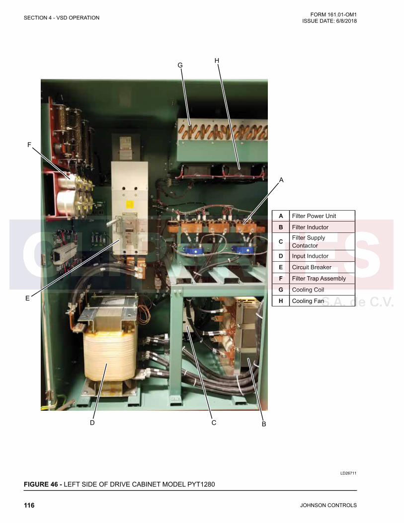
JOHNSON CONTROLS116
FORM 161.01-OM1 ISSUE DATE: 6/8/2018SECTION 4 - VSD OPERATION
LD26711
BD
E
F
GH
A
C
A Filter Power Unit
B Filter Inductor
C Filter Supply Contactor
D Input Inductor
E Circuit Breaker
F Filter Trap Assembly
G Cooling Coil
H Cooling Fan
FIGURE 46 - LEFT SIDE OF DRIVE CABINET MODEL PYT1280
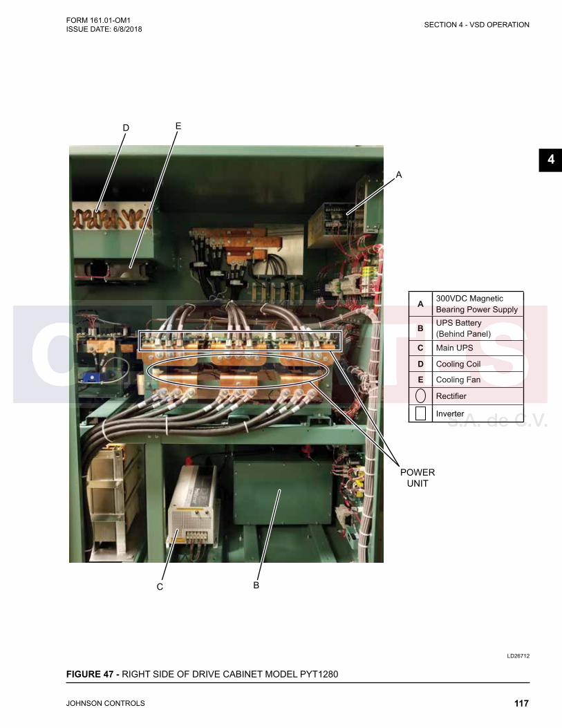
JOHNSON CONTROLS 117
SECTION 4 - VSD OPERATIONFORM 161.01-OM1 ISSUE DATE: 6/8/2018
4
LD26712
BC
POWERUNIT
A
D E
A 300VDC Magnetic Bearing Power Supply
C Main UPS
B UPS Battery (Behind Panel)
D Cooling Coil
E Cooling Fan
Rectifier
Inverter
FIGURE 47 - RIGHT SIDE OF DRIVE CABINET MODEL PYT1280
JOHNSON CONTROLS118
FORM 161.01-OM1 ISSUE DATE: 6/8/2018SECTION 4 - VSD OPERATION
THIS PAGE INTENTIONALLY LEFT BLANK.
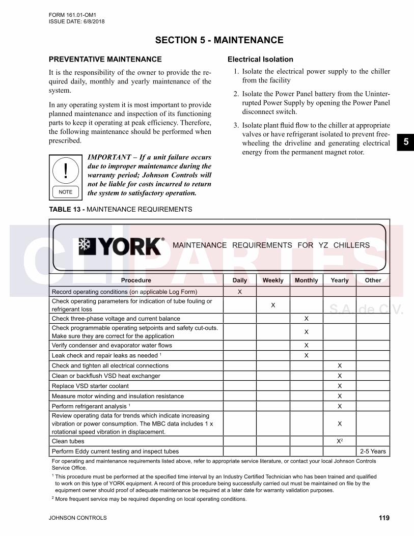
JOHNSON CONTROLS 119
FORM 161.01-OM1 ISSUE DATE: 6/8/2018
5
SECTION 5 - MAINTENANCE
PREVENTATIVE MAINTENANCEIt is the responsibility of the owner to provide the re-quired daily, monthly and yearly maintenance of the system.
In any operating system it is most important to provide planned maintenance and inspection of its functioning parts to keep it operating at peak efficiency. Therefore, the following maintenance should be performed when prescribed.
IMPORTANT – If a unit failure occurs due to improper maintenance during the warranty period; Johnson Controls will not be liable for costs incurred to return the system to satisfactory operation.
Electrical Isolation1. Isolate the electrical power supply to the chiller
from the facility
2. Isolate the Power Panel battery from the Uninter-rupted Power Supply by opening the Power Panel disconnect switch.
3. Isolate plant fluid flow to the chiller at appropriate valves or have refrigerant isolated to prevent free-wheeling the driveline and generating electrical energy from the permanent magnet rotor.
TABLE 13 - MAINTENANCE REQUIREMENTS
Procedure Daily Weekly Monthly Yearly Other
Record operating conditions (on applicable Log Form) XCheck operating parameters for indication of tube fouling or refrigerant loss
X
Check three-phase voltage and current balance XCheck programmable operating setpoints and safety cut-outs. Make sure they are correct for the application
X
Verify condenser and evaporator water flows X
Leak check and repair leaks as needed 1 X
Check and tighten all electrical connections X
Clean or backflush VSD heat exchanger X
Replace VSD starter coolant X
Measure motor winding and insulation resistance X
Perform refrigerant analysis 1 XReview operating data for trends which indicate increasing vibration or power consumption. The MBC data includes 1 x rotational speed vibration in displacement.
X
Clean tubes X2
Perform Eddy current testing and inspect tubes 2-5 YearsFor operating and maintenance requirements listed above, refer to appropriate service literature, or contact your local Johnson Controls Service Office.1 This procedure must be performed at the specified time interval by an Industry Certified Technician who has been trained and qualified
to work on this type of YORK equipment. A record of this procedure being successfully carried out must be maintained on file by the equipment owner should proof of adequate maintenance be required at a later date for warranty validation purposes.
2 More frequent service may be required depending on local operating conditions.
MAINTENANCE REQUIREMENTS FOR YZ CHILLERS
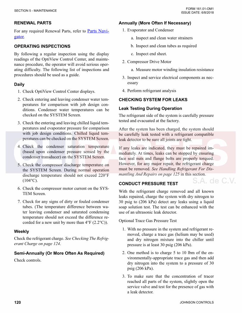
JOHNSON CONTROLS120
FORM 161.01-OM1 ISSUE DATE: 6/8/2018SECTION 5 - MAINTENANCE
RENEWAL PARTS
For any required Renewal Parts, refer to Parts Navi-gator.
OPERATING INSPECTIONSBy following a regular inspection using the display readings of the OptiView Control Center, and mainte-nance procedure, the operator will avoid serious oper-ating difficulty. The following list of inspections and procedures should be used as a guide.
Daily1. Check OptiView Control Center displays.
2. Check entering and leaving condenser water tem-peratures for comparison with job design con-ditions. Condenser water temperatures can be checked on the SYSTEM Screen.
3. Check the entering and leaving chilled liquid tem-peratures and evaporator pressure for comparison with job design conditions. Chilled liquid tem-peratures can be checked on the SYSTEM Screen.
4. Check the condenser saturation temperature (based upon condenser pressure sensed by the condenser transducer) on the SYSTEM Screen.
5. Check the compressor discharge temperature on the SYSTEM Screen. During normal operation discharge temperature should not exceed 220°F (104°C).
6. Check the compressor motor current on the SYS-TEM Screen.
7. Check for any signs of dirty or fouled condenser tubes. (The temperature difference between wa-ter leaving condenser and saturated condensing temperature should not exceed the difference re-corded for a new unit by more than 4°F (2.2°C)).
WeeklyCheck the refrigerant charge. See Checking The Refrig-erant Charge on page 124.
Semi-Annually (Or More Often As Required)Check controls.
Annually (More Often If Necessary)1. Evaporator and Condenser
a. Inspect and clean water strainers
b. Inspect and clean tubes as required
c. Inspect end sheet.
2. Compressor Drive Motor
a. Measure motor winding insulation resistance
3. Inspect and service electrical components as nec-essary
4. Perform refrigerant analysis
CHECKING SYSTEM FOR LEAKS
Leak Testing During OperationThe refrigerant side of the system is carefully pressure tested and evacuated at the factory.
After the system has been charged, the system should be carefully leak tested with a refrigerant compatible leak detector to be sure all joints are tight.
If any leaks are indicated, they must be repaired im-mediately. At times, leaks can be stopped by ensuring face seal nuts and flange bolts are properly torqued. However, for any major repair, the refrigerant charge must be removed. See Handling Refrigerant For Dis-mantling And Repairs on page 125 in this section.
CONDUCT PRESSURE TESTWith the refrigerant charge removed and all known leaks repaired, charge the system with dry nitrogen to 30 psig to (206 kPa) detect any leaks using a liquid soap solution test. The test can be enhanced with the use of an ultrasonic leak detector.
Optional Trace Gas Pressure Test
1. With no pressure in the system and refrigerant re-moved, charge a trace gas (helium may be used) and dry nitrogen mixture into the chiller until pressure is at least 30 psig (206 kPa).
2. One method is to charge 5 to 10 lbm of the en-vironmentally-appropriate trace gas and then add dry nitrogen into the system to a pressure of 30 psig (206 kPa).
3. To make sure that the concentration of tracer reached all parts of the system, slightly open the service valve and test for the presence of gas with a leak detector.
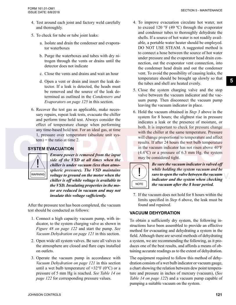
JOHNSON CONTROLS 121
SECTION 5 - MAINTENANCEFORM 161.01-OM1 ISSUE DATE: 6/8/2018
5
4. Test around each joint and factory weld carefully and thoroughly.
5. To check for tube or tube joint leaks:
a. Isolate and drain the condenser and evapora-tor waterboxes
b. Purge the waterboxes and tubes with dry ni-trogen through the vents or drains until the detector does not indicate
c. Close the vents and drains and wait an hour
d. Open a vent or drain and insert the leak de-tector. If a leak is detected, the heads must be removed and the source of the leak de-termined as outlined in the Condensers and Evaporators on page 125 in this section.
6. Recover the test gas as applicable, make neces-sary repairs, repeat leak tests, evacuate the chiller and perform time hold test. Always consider the effect of temperature change when performing any time-based hold test. For an ideal gas, at time 1, pressure over temperature (absolute unit sys-tem) = the ratio at time 2.
SYSTEM EVACUATIONEnsure power is removed from the input side of the VSD at all times when the chiller is under vacuum (less than atmo-spheric pressure). The VSD maintains voltage to ground on the motor when the chiller is off while voltage is available to the VSD. Insulating properties in the mo-tor are reduced in vacuum and may not insulate this voltage sufficiently.
After the pressure test has been completed, the vacuum test should be conducted as follows:
1. Connect a high capacity vacuum pump, with in-dicator, to the system charging valve as shown in Figure 48 on page 122 and start the pump. See Vacuum Dehydration on page 121 in this section.
2. Open wide all system valves. Be sure all valves to the atmosphere are closed and flare caps installed on outlets.
3. Operate the vacuum pump in accordance with Vacuum Dehydration on page 121 in this section until a wet bulb temperature of +32°F (0°C) or a pressure of 5 mm Hg is reached. See Table 14 on page 122 for corresponding pressure values.
4. To improve evacuation circulate hot water, not to exceed 120 °F (49 ºC) through the evaporator and condenser tubes to thoroughly dehydrate the shells. If a source of hot water is not readily avail-able, a portable water heater should be employed. DO NOT USE STEAM. A suggested method is to connect a hose between the source of hot water under pressure and the evaporator head drain con-nection, out the evaporator vent connection, into the condenser head drain and out the condenser vent. To avoid the possibility of causing leaks, the temperature should be brought up slowly so that the tubes and shell are heated evenly.
5. Close the system charging valve and the stop valve between the vacuum indicator and the vac-uum pump. Then disconnect the vacuum pump leaving the vacuum indicator in place.
6. Hold the vacuum obtained in Step 3 above in the system for 8 hours; the slightest rise in pressure indicates a leak or the presence of moisture, or both. It is important to check for pressure change with the chiller at the same temperature. Pressure will change proportional to temperature and affect results. If after 24 hours the wet bulb temperature in the vacuum indicator has not risen above 40°F (4.4°C) or a pressure of 6.3 mm Hg, the system may be considered tight.
Be sure the vacuum indicator is valved off while holding the system vacuum and be sure to open the valve between the vacuum indicator and the system when checking the vacuum after the 8 hour period.
7. If the vacuum does not hold for 8 hours within the limits specified in Step 6 above, the leak must be found and repaired.
VACUUM DEHYDRATIONTo obtain a sufficiently dry system, the following in-structions have been assembled to provide an effective method for evacuating and dehydrating a system in the field. Although there are several methods of dehydrating a system, we are recommending the following, as it pro-duces one of the best results, and affords a means of ob-taining accurate readings as to the extent of dehydration.
The equipment required to follow this method of dehy-dration consists of a wet bulb indicator or vacuum gauge, a chart showing the relation between dew point tempera-ture and pressure in inches of mercury (vacuum), (See Table 14 on page 122) and a vacuum pump capable of pumping a suitable vacuum on the system.

JOHNSON CONTROLS122
FORM 161.01-OM1 ISSUE DATE: 6/8/2018SECTION 5 - MAINTENANCE
TABLE 14 - SYSTEM PRESSURES
*GAUGE ABSOLUTEBOILING
TEMPERATURES OF WATER °F
INCHES OF MERCURY (HG) BELOW ONE
STANDARD ATMOSPHERE
PSIAMILLIMETERS OF MERCURY
(HG)MICRONS
0" 14.6960 760.00 760,000 212
10.240" 9.6290 500.00 500,000 192
22.050" 3.8650 200.00 200,000 151
25.980" 1.9350 100.00 100,000 124
27.950" 0.9680 50.00 50,000 101
28.940" 0.4810 25.00 25,000 78
29.530" 0.1920 10.00 10,000 52
29.670" 0.1220 6.30 6,300 40
29.720" 0.0990 5.00 5,000 35
29.842" 0.0390 2.00 2,000 15
29.882" 0.0190 1.00 1,000 1
29.901" 0.0100 0.50 500 –11
29.917" 0.0020 0.10 100 –38
29.919" 0.0010 0.05 50 –50
29.9206" 0.0002 0.01 10 –70
29.921" 0 0 0
*One standard atmosphere = 14.696 PSIA = 760 mm Hg. absolute pressure at 32°F = 29.921 inches Hg. absolute at 32°F
NOTES: PSIG = Lbs. per sq. in. gauge pressure = Pressure above atmosphere PSIA = Lbs. per sq. in. absolute pressure = Sum of gauge plus atmospheric pressure
Water Freezes
LD26725
VACUUM PUMP
STOP VALVE
WET BUBL TEMPERATUREINDICATOR ORVACUUM GAUGE
CHARGING VALVE
FIGURE 48 - EVACUATION OF CHILLER

JOHNSON CONTROLS 123
SECTION 5 - MAINTENANCEFORM 161.01-OM1 ISSUE DATE: 6/8/2018
5
OperationDehydration of a refrigerant system can be obtained by this method because the water present in the system reacts much as a refrigerant would. By pulling down the pressure in the system to a point where its satu-ration temperature is considerably below that of room temperature, heat will flow from the room through the walls of the system and vaporize the water, allowing a large percentage of it to be removed by the vacuum pump. The length of time necessary for the dehydra-tion of a system is dependent on the size or volume of the system, the capacity and efficiency of the vacuum pump, the room temperature and the quantity of water present in the system. By the use of the vacuum indi-cator as suggested, the test tube will be evacuated to the same pressure as the system, and the distilled water will be maintained at the same saturation temperature as any free water in the system, and this temperature can be observed on the thermometer.
If the system has been pressure tested and found to be tight prior to evacuation, then the saturation tempera-ture recordings should follow a curve similar to the typical saturation curve shown as in Figure 49 on page 123 below.
The temperature of the water in the test tube will drop as the pressure decreases, until the boiling point is reached, at which point the temperature will level off and remain at this level until all of the water in the shell is vaporized. When this final vaporization has taken place the pressure and temperature will continue to drop until eventually a temperature of 35°F (1.6°C) or a pressure of 5 mm Hg. is reached.
LD26726
FIGURE 49 - SATURATION CURVE
When this point is reached, practically all of the air has been evacuated from the system, but there is still a small amount of moisture left. In order to provide a medium for carrying this residual moisture to the vacuum pump, nitrogen should be introduced into the system to bring it to atmospheric pressure and the indi-cator temperature will return to approximately ambient temperature. Close off the system again, and start the second evacuation.
The relatively small amount of moisture left will be carried out through the vacuum pump and the tem-perature or pressure shown by the indicator should drop uniformly until it reaches a temperature of 35°F (1.6°C) or a pressure of 5 mm Hg.
When the vacuum indicator registers this tempera-ture or pressure, it is a positive sign that the system is evacuated and dehydrated to the recommended limit. If this level cannot be reached, it is evident that there is a leak somewhere in the system. Any leaks must be cor-rected before the indicator can be pulled down to 35°F (1.6°C) or 5 mm Hg. in the primary evacuation.
During the primary pulldown, keep a careful watch on the wet bulb indicator temperature, and do not let it fall below 35°F (1.6°C). If the temperature is allowed to fall to 32°F (0°C), the water in the test tube will freeze, and the result will be a faulty temperature reading.
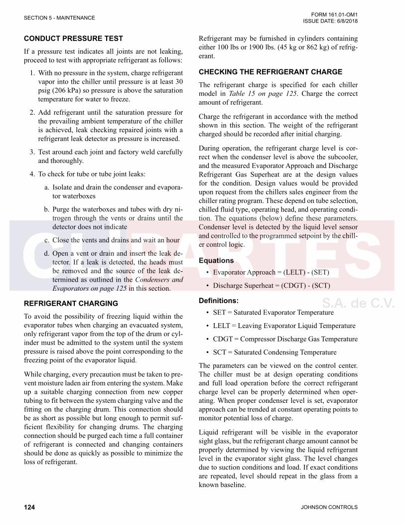
JOHNSON CONTROLS124
FORM 161.01-OM1 ISSUE DATE: 6/8/2018SECTION 5 - MAINTENANCE
CONDUCT PRESSURE TESTIf a pressure test indicates all joints are not leaking, proceed to test with appropriate refrigerant as follows:
1. With no pressure in the system, charge refrigerant vapor into the chiller until pressure is at least 30 psig (206 kPa) so pressure is above the saturation temperature for water to freeze.
2. Add refrigerant until the saturation pressure for the prevailing ambient temperature of the chiller is achieved, leak checking repaired joints with a refrigerant leak detector as pressure is increased.
3. Test around each joint and factory weld carefully and thoroughly.
4. To check for tube or tube joint leaks:
a. Isolate and drain the condenser and evapora-tor waterboxes
b. Purge the waterboxes and tubes with dry ni-trogen through the vents or drains until the detector does not indicate
c. Close the vents and drains and wait an hour
d. Open a vent or drain and insert the leak de-tector. If a leak is detected, the heads must be removed and the source of the leak de-termined as outlined in the Condensers and Evaporators on page 125 in this section.
REFRIGERANT CHARGINGTo avoid the possibility of freezing liquid within the evaporator tubes when charging an evacuated system, only refrigerant vapor from the top of the drum or cyl-inder must be admitted to the system until the system pressure is raised above the point corresponding to the freezing point of the evaporator liquid.
While charging, every precaution must be taken to pre-vent moisture laden air from entering the system. Make up a suitable charging connection from new copper tubing to fit between the system charging valve and the fitting on the charging drum. This connection should be as short as possible but long enough to permit suf-ficient flexibility for changing drums. The charging connection should be purged each time a full container of refrigerant is connected and changing containers should be done as quickly as possible to minimize the loss of refrigerant.
Refrigerant may be furnished in cylinders containing either 100 lbs or 1900 lbs. (45 kg or 862 kg) of refrig-erant.
CHECKING THE REFRIGERANT CHARGEThe refrigerant charge is specified for each chiller model in Table 15 on page 125. Charge the correct amount of refrigerant.
Charge the refrigerant in accordance with the method shown in this section. The weight of the refrigerant charged should be recorded after initial charging.
During operation, the refrigerant charge level is cor-rect when the condenser level is above the subcooler, and the measured Evaporator Approach and Discharge Refrigerant Gas Superheat are at the design values for the condition. Design values would be provided upon request from the chillers sales engineer from the chiller rating program. These depend on tube selection, chilled fluid type, operating head, and operating condi-tion. The equations (below) define these parameters. Condenser level is detected by the liquid level sensor and controlled to the programmed setpoint by the chill-er control logic.
Equations• Evaporator Approach = (LELT) - (SET)
• Discharge Superheat = (CDGT) - (SCT)
Definitions:• SET = Saturated Evaporator Temperature
• LELT = Leaving Evaporator Liquid Temperature
• CDGT = Compressor Discharge Gas Temperature
• SCT = Saturated Condensing Temperature
The parameters can be viewed on the control center. The chiller must be at design operating conditions and full load operation before the correct refrigerant charge level can be properly determined when oper-ating. When proper condenser level is set, evaporator approach can be trended at constant operating points to monitor potential loss of charge.
Liquid refrigerant will be visible in the evaporator sight glass, but the refrigerant charge amount cannot be properly determined by viewing the liquid refrigerant level in the evaporator sight glass. The level changes due to suction conditions and load. If exact conditions are repeated, level should repeat in the glass from a known baseline.

JOHNSON CONTROLS 125
SECTION 5 - MAINTENANCEFORM 161.01-OM1 ISSUE DATE: 6/8/2018
5
CONDENSERS AND EVAPORATORS
GeneralMaintenance of condenser and evaporator shells is im-portant to provide trouble free operation of the chiller. The water side of the tubes in the shell must be kept clean and free from scale.
The major portion of maintenance on the condenser and evaporator will deal with the maintaining the water side of the condenser and evaporator in a clean condi-tion.
The use of untreated water in cooling towers, closed water systems, etc. frequently results in one or more of the following:
1. Scale Formation
2. Corrosion or Rusting
3. Slime and Algae Formation
It is therefore to the benefit of the user to provide for proper water treatment to provide for a longer and more economical life of the equipment. The following recommendation should be followed in determining the condition of the water side of the condenser and evaporator tubes.
TABLE 15 - APPROXIMATE REFRIGERANT AND WATER WEIGHT
EVAPORATOR CONDENSER REFRIGERANT WEIGHT LBS (KG)*
WATER WEIGHT LBS (KG)**
FB2910 CA2110 579 (263) 1375 (625)FB2912 SA2512 746 (339) 1870 (850)FA3312 SA2512 770 (350) 2035 (925)FA3312 SA2512 869 (395) 2035 (925)FA3314 SA3314 1177 (535) 3520 (1600)FA3314 SA3314 1302 (592) 4125 (1875)FA3914 CA3314 1751 (796) 4015 (1825)FA3916 SA3916 2105 (957) 5665 (2475)FA4816 SA3916 2451 (1114) 6820 (3100)FA4816 CA3916 2779 (1263) 6765 (3075)FB4818 SA4418 3291 (1496) 8635 (3925)FB5618 SS4418 3577 (1626) 9680 (4400)
*Refrigerant Weight based on maximum tube bundle. ** Water Weight is the total water in both shells and for 150PSI, 2-pass, compact water boxes.
HANDLING REFRIGERANT FOR DISMANTLING AND REPAIRSIf it becomes necessary to open any part of the refriger-ant system for repairs, it will be necessary to remove the charge before opening any part of the unit. If the chiller is equipped with optional valves, the refrigerant can be isolated in either the condenser or evaporator / compressor while making any necessary repairs.
COMPRESSOR AND MOTOR1. Check mounting screws and piping joint nuts fre-
quently to insure tightness.
2. Test motor windings annually to check for dete-rioration of windings.
Electrical test of motor winding resistance should be performed by a qualified service technician because it involves determination of power leads between the motor and the VSD. Results from these winding insu-lation resistance tests should be trended each interval to determine degradation in motor windings.

JOHNSON CONTROLS126
FORM 161.01-OM1 ISSUE DATE: 6/8/2018SECTION 5 - MAINTENANCE
1. The condenser tubes should be cleaned annually or earlier if conditions warrant. If the temperature difference between the water off the condenser and the condenser liquid temperature is more than 4°F (2°C) greater than the difference recorded on a new unit, it is a good indication that the con-denser tubes require cleaning. See Cleaning Evap-orator and Condenser Tubes on page 126 in this section for condenser tube cleaning instructions.
2. The evaporator tubes under normal circumstances will not require cleaning. If the temperature dif-ference between the refrigerant and the chilled water increases slowly over the operating season, it is an indication that the evaporator tubes may be fouling or that there may be a water bypass in the water box requiring gasket replacement or refrig-erant may have leaked from the chiller.
Chemical Water TreatmentSince the mineral content of the water circulated through evaporators and condensers varies with almost every source of supply, it is possible that the water be-ing used may corrode the tubes or deposit heat resistant scale in them. Reliable water treatment companies are available in most larger cities to supply a water treat-ing process which will greatly reduce the corrosive and scale forming properties of almost any type of water.
As a preventive measure against scale and corrosion and to prolong the life of evaporator and condenser tubes, a chemical analysis of the water should be made preferably before the system is installed. A reliable wa-ter treatment company can be consulted to determine whether water treatment is necessary, and if so, to fur-nish the proper treatment for the particular water con-dition.
Cleaning Evaporator and Condenser Tubes
EvaporatorIt is difficult to determine by any particular test wheth-er possible lack of performance of the evaporator is due to fouled tubes alone or due to a combination of troubles. Trouble which may be due to fouled tubes is indicated when, over a period of time, the cooling ca-pacity decreases and the split (temperature difference between water leaving the evaporator and the refriger-ant temperature in the evaporator) increases. A gradual drop-off in cooling capacity can also be caused by a gradual leak of refrigerant from the system or by a combination of fouled tubes and shortage of refriger-ant charge.
CondenserIn a condenser, trouble due to fouled tubes is usually indicated by a steady rise in head pressure, over a pe-riod of time, accompanied by a steady rise in condens-ing temperature.
Tube FoulingFouling of the tubes can be due to deposits of two types as follows:
1. Rust or sludge – which finds its way into the tubes and accumulates there. This material usually does not build up on the inner tube surfaces as scale, but does interfere with the heat transfer. Rust or sludge can generally be removed from the tubes by a thorough brushing process.
2. Scale – due to mineral deposits. These deposits, even though very thin and scarcely detectable upon physical inspection, are highly resistant to heat transfer. They can be removed most effec-tively by circulating an acid solution through the tubes using skilled experts as described below.
Tube Cleaning Procedures
Brush Cleaning of TubesIf the tube consists of dirt and sludge, it can usually be removed by means of the brushing process. Drain the water sides of the circuit to be cleaned (cooling wa-ter or chilled water) remove the heads and thoroughly clean each tube with a soft bristle nylon brush. DO NOT USE A STEEL BRISTLE BRUSH. A steel brush may damage the tubes.
Improved results can be obtained by admitting water into the tube during the cleaning process. This can be done by mounting the brush on a suitable length of 1/8" pipe with a few small holes at the brush end and con-necting the other end by means of a hose to the water supply.
The tubes should always be brush cleaned before acid cleaning.
Acid Cleaning of TubesIf the tubes are fouled with a hard scale deposit, they may require acid cleaning. It is important that before acid cleaning, the tubes be cleaned by the brushing process described above. If the relatively loose foreign material is removed before the acid cleaning, the acid solution will have less material to dissolve and flush

JOHNSON CONTROLS 127
SECTION 5 - MAINTENANCEFORM 161.01-OM1 ISSUE DATE: 6/8/2018
5
from the tubes with the result that a more satisfactory cleaning job will be accomplished with a probable sav-ing of time.
Acid cleaning should only be performed by an expert. Please consult your local water treatment representative for as-sistance in removing scale buildup and preventative maintenance programs to eliminate future problems.
Commercial Acid CleaningIn many major cities, commercial organizations now offer a specialized service of acid cleaning evaporators and condensers. If acid cleaning is required, Johnson Controls recommends the use of this type of organiza-tion. The Dow Industries Service Division of the Dow Chemical Company, Tulsa, Oklahoma, with branches in principal cities is one of the most reliable of these companies.
Testing for Evaporator and Condenser Tube LeaksEvaporator and condenser tube leaks in refrigerant cir-cuits may result in refrigerant leaking into the water circuit, or water leaking into the shell depending on the pressure levels. If refrigerant is leaking into the water, it can be detected at the liquid head vents after a period of shutdown. If water is leaking into the refrigerant, system capacity and efficiency will drop off sharply. If a tube is leaking and water has entered the system, the evaporator and condenser should be valved off from the rest of the water circuit and drained immediately to prevent severe rusting and corrosion. The refrigerant system should then be drained and purged with dry ni-trogen to prevent severe rusting and corrosion. If a tube leak is indicated, the exact location of the leak may be determined as follows:
1. Remove the heads and listen at each section of tubes for a hissing sound that would indicate gas leakage. This will assist in locating the section of tubes to be further investigated. If the probable location of the leaky tubes has been determined, treat that section in the following manner (if the location is not definite, all the tubes will require investigations).
2. Wash off both tube heads and the ends of all tubes with water.
3. With nitrogen or dry air, blow out the tubes to clear them of traces of refrigerant laden moisture from the circulation water. As soon as the tubes are clear, a cork should be driven into each end of the tube. Pressurize the dry system with 50 to 100 PSIG (345 to 690 kPa) of nitrogen. Repeat this with all of the other tubes in the suspected section or, if necessary, with all the tubes in the evaporator or condenser. Allow the evaporator or condenser to remain corked up to 12 to 24 hours before proceeding. Depending upon the amount of leakage, the corks may blow from the end of a tube, indicating the location of the leakage. If not, if will be necessary to make a very thorough test with the leak detector.
4. After the tubes have been corked for 12 to 24 hours, it is recommended that two men working at both ends of the evaporator carefully test each tube – one man removing corks at one end and the other at the opposite end to remove corks and handle the leak detector. Start with the top row of tubes in the section being investigated. Remove the corks at the ends of one tube simultaneously and insert the exploring tube for 5 seconds – this should be long enough to draw into the detec-tor any refrigerant gas that might have leaked through the tube walls. A fan placed at the end of the evaporator opposite the detector will assure that any leakage will travel through the tube to the detector.
5. Mark any leaking tubes for later identification.
6. If any of the tube sheet joints are leaking, the leak should be indicated by the detector. If a tube sheet leak is suspected, its exact location may be found by using a soap solution. A continuous buildup of bubbles around a tube indicates a tube sheet leak.
ELECTRICAL CONTROLSEnsure electrical connections are tight and connectors are secure annually.
It is important that the factory settings of controls (op-eration and safety) not be changed. If the settings are changed without Johnson Controls approval, the war-ranty will be jeopardized.

JOHNSON CONTROLS128
FORM 161.01-OM1 ISSUE DATE: 6/8/2018SECTION 5 - MAINTENANCE
AUTOMATIC BATTERY HEALTH TEST – DURING SHUTDOWNFor periodic maintenance or to diagnose battery faults or warnings, a battery health test can be performed. This test is initiated from the Power Panel screen of the Optiview panel to monitor battery voltage while under a known load. This will ensure that the battery has enough capacity left to withstand a power failure event. The test is available though operator access level or higher.
At the keypad, log in at Operator access level using ac-cess level code 9 6 7 5 or a higher level.
Navigate to Compressor – Power Panel screen.
On the Power Panel screen, the “Start Battery Test” button is shown and the function available when all of the following are true:
• Access Level is Operator or higher
• Chiller State is Stopped
• Safety Stop push-button is depressed
• The Local Run/Stop is set to Stop
When the “Start Battery Test” button is pressed the Bat-tery Health Test is initiated. When the Battery Health Test is in progress, this button changes to a “Cancel Battery Test” button to cancel the active Battery Health Test in progress if needed. The test proceeds as follows:
The panel instructs “UPS Battery Test - Disconnect 3-phase line power to the chiller now”. At that time, re-move three-phase power to the chiller. Once the power is removed, the UPS becomes available for a limit of 10 minutes for performance of the test.
When the panel detects control voltage is low and UPS is in Inverter mode due to loss of the line power, the panel displays “UPS Battery Test - Evaluating Bat-tery”. The MBC is then commanded to Levitation. Af-ter the MBC reports to Optiview that it is in Levitation mode, the battery voltage is monitored for the next 60 seconds.
The following constitute a fail result:
• If Battery Voltage drops to less than the Inverter Low Battery Voltage Threshold (Default 11.0 V) (UPS – Inverter Low Battery Voltage fault thresh-old) the test fails and ends
• If the test takes longer than 75 seconds the test fails and ends
• If the UPS shuts down (OptiView will lose power) due to voltage, fuses, disconnect, or any other rea-son the test fails and the Optiview displays a fault on next power up stating that the battery health test has failed. This fault can be cleared by run-ning a successful battery health test
If the “UPS – Inverter Low Battery Voltage” fault is not set by the end of the 60 second test (Battery Volt-age stays above the threshold), the battery evaluation is considered good.
Next, the control ceases MBC levitation. If this step takes longer than 15 seconds, the test fails and ends.
Then the panel instructs “Reconnect 3-phase line power to the chiller now”. At that time, reapply three-phase power to the chiller. The full test successfully ends when Optiview detects the control voltage has returned.
If the 10 minute power loss holdup timer runs out (Op-tiView power will be lost due to turning off UPS In-verter) before the test completes and power is restored the test is considered failed.
“UPS Battery Health Test Successful” is displayed for 10 seconds when the test passes.
“UPS Battery Health Test Failed – Step X” (Where X is the step that failed) is displayed when the test fails. It remains while the “Warning – UPS – Battery Test Failed” warning is active. It and the warning will be cleared when a Battery Health Test completes success-fully.
For a fail, the following steps may be indicated as the fail point:
• Step 2 is when the Optiview is waiting to sense line power removed – typically the user has taken too long and exceeded 10 minute test time
• Step 3 is during the 60 second battery voltage monitoring under Levitation load – typically would be a bad battery
• Step 4 is after completion of the 60 second moni-toring and waiting for successful automatic de-levitation – would indicate some unplanned fail-ure of the control or communication
• Step 5 is waiting to sense line power restored – typically the user has taken too long and exceeded 10 minute test time

JOHNSON CONTROLS 129
FORM 161.01-OM1 ISSUE DATE: 6/8/2018
6
SECTION 6 - PRINTING
PRINTING OVERVIEWA laptop computer can be connected to the Control Center’s Microboard to print the following reports. The screen from which each report can be generated is listed below in parenthesis.
• Status ‑ System parameters (Printer, Home)
• Setpoints ‑ Programmed values of all setpoints (Printer, Setpoints)
• Schedule ‑ Value of programmed daily schedule (Printer, Schedule)
• Sales Order ‑ Information about SALES ORDER Screen (Printer, Sales Order)
• History ‑ System parameters at the time of the last normal stop, last fault while running and last 10 faults, whether running or not (Printer, History)
• Cycling or Safety Shutdown Initiated Print ‑ Snapshot of all system parameters at instant of shutdown. Automatically occurs if printer is con-nected at time of shutdown.
• Trend ‑ Prints a snapshot of the existing TREND Screen data or prints new data collected after the TREND PRINT key is pressed.
A laptop computer can be permanently connected to the Control Center or connected as required to generate a report. If permanently connected, a DATA LOGGING feature can produce a status report automatically, be-ginning at an Operator selected start time and occur-ring at an Operator selected interval thereafter. An SD data card can log chiller parameters every 0.1 to 60 seconds (Default 1.0 seconds) and reviewed in Excel.
The following figures are examples of the different print reports.
• Status or History - Figure 52 on page 132
• Setpoints - Figure 53 on page 133
• Schedule - Figure 54 on page 135
• Sales Order - Figure 55 on page 135
• Security Log - Figure 56 on page 136
• Trend - Figure 57 on page 137
• CUSTOM Screen - Figure 58 on page 137
Automatic Data LoggingAccess Level Required: OPERATORIf automatic data logging is desired, a status report can be automatically printed at a specified interval begin-ning at a specified time, using the PRINTER Screen. The interval is programmable over the range of 1 min-ute to 1440 minutes in 1 minute increments. The first print will occur at the programmed START time and occur at the programmed Output Interval thereafter. The time remaining until the next print is displayed on the PRINTER Screen.
• Automatic Printer Logging - Enables and disables automatic data logging.
• Log Start Time ‑ Enter the time the first print is desired.
• Output Interval - Enter the desired interval be-tween prints.
DOWNLOADING SYSTEM PRINTS TO A LAPTOPDownloading system histories to a file is another use-ful method to capture system operating conditions. The following instructions are used to establish communi-cation between the OptiView Control Panel and a lap-top computer running any terminal emulation program such as HyperTerminal, TeraTerm or PuTTy.
1. Connect the laptop computer to the OptiView as described below.
LAPTOP(RS-232 SERIAL
PORT)
OPTIVIEW(COM 1)
PIN DESC Connector Terminal2 RX to J2 4 (TXD1)4 DTR to J2 2 (DSR1)5 GND to J2 8 GND
2. On OptiView Printer Screen, select “PC”. This will allow faster data download than the printer selections. On Setpoints - Setup - Comms screen, ensure the printer settings match “h. Port settings” see below.
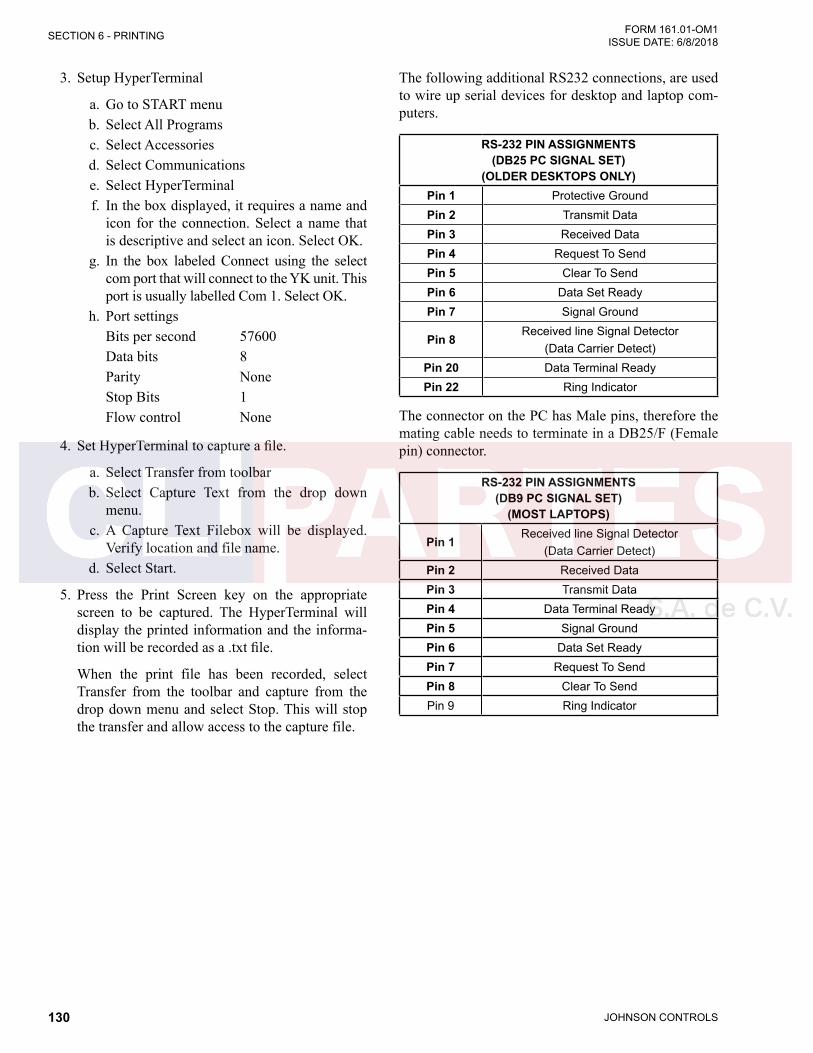
JOHNSON CONTROLS130
FORM 161.01-OM1 ISSUE DATE: 6/8/2018SECTION 6 - PRINTING
3. Setup HyperTerminal
a. Go to START menub. Select All Programsc. Select Accessoriesd. Select Communicationse. Select HyperTerminalf. In the box displayed, it requires a name and
icon for the connection. Select a name that is descriptive and select an icon. Select OK.
g. In the box labeled Connect using the select com port that will connect to the YK unit. This port is usually labelled Com 1. Select OK.
h. Port settingsBits per second 57600Data bits 8Parity NoneStop Bits 1Flow control None
4. Set HyperTerminal to capture a file.
a. Select Transfer from toolbarb. Select Capture Text from the drop down
menu.c. A Capture Text Filebox will be displayed.
Verify location and file name.d. Select Start.
5. Press the Print Screen key on the appropriate screen to be captured. The HyperTerminal will display the printed information and the informa-tion will be recorded as a .txt file.
When the print file has been recorded, select Transfer from the toolbar and capture from the drop down menu and select Stop. This will stop the transfer and allow access to the capture file.
The following additional RS232 connections, are used to wire up serial devices for desktop and laptop com-puters.
RS-232 PIN ASSIGNMENTS (DB25 PC SIGNAL SET)
(OLDER DESKTOPS ONLY)Pin 1 Protective GroundPin 2 Transmit DataPin 3 Received DataPin 4 Request To SendPin 5 Clear To SendPin 6 Data Set ReadyPin 7 Signal Ground
Pin 8Received line Signal Detector
(Data Carrier Detect)Pin 20 Data Terminal ReadyPin 22 Ring Indicator
The connector on the PC has Male pins, therefore the mating cable needs to terminate in a DB25/F (Female pin) connector.
RS-232 PIN ASSIGNMENTS (DB9 PC SIGNAL SET)
(MOST LAPTOPS)
Pin 1Received line Signal Detector
(Data Carrier Detect)Pin 2 Received DataPin 3 Transmit DataPin 4 Data Terminal ReadyPin 5 Signal GroundPin 6 Data Set ReadyPin 7 Request To SendPin 8 Clear To SendPin 9 Ring Indicator
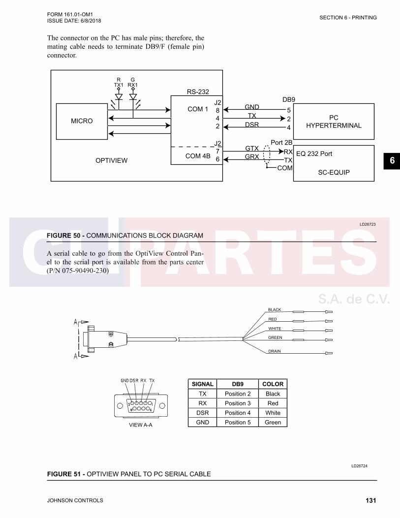
JOHNSON CONTROLS 131
SECTION 6 - PRINTINGFORM 161.01-OM1 ISSUE DATE: 6/8/2018
6
The connector on the PC has male pins; therefore, the mating cable needs to terminate DB9/F (female pin) connector.
LD26723
MICRO
OPTIVIEW
RTX1
GRX1
PC HYPERTERMINAL
EQ 232 Port
SC-EQUIP
COM 1
RS-232
TX
DB9
25
4
Port 2BRXTX
COM
GND
DSR
GTXGRXCOM 4B
J2842
J276
FIGURE 50 - COMMUNICATIONS BLOCK DIAGRAM
A serial cable to go from the OptiView Control Pan-el to the serial port is available from the parts center (P/N 075-90490-230)
LD26724
VIEW A-A
BLACK
RED
WHITE
GREEN
DRAIN
SIGNAL DB9 COLORTX Position 2 BlackRX Position 3 Red
DSR Position 4 WhiteGND Position 5 Green
FIGURE 51 - OPTIVIEW PANEL TO PC SERIAL CABLE
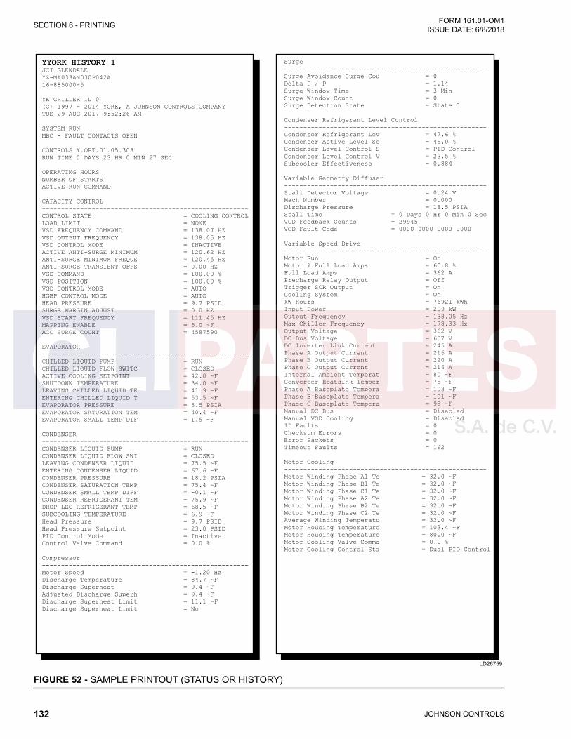
JOHNSON CONTROLS132
FORM 161.01-OM1 ISSUE DATE: 6/8/2018SECTION 6 - PRINTING
FIGURE 52 - SAMPLE PRINTOUT (STATUS OR HISTORY)
LD26759
YYORK HISTORY 1JCI GLENDALEYZ-MA033AN030P042A16-885000-5
YK CHILLER ID 0(C) 1997 - 2014 YORK, A JOHNSON CONTROLS COMPANYTUE 29 AUG 2017 9:52:26 AM
SYSTEM RUNMBC - FAULT CONTACTS OPEN
CONTROLS Y.OPT.01.05.308RUN TIME 0 DAYS 23 HR 0 MIN 27 SEC
OPERATING HOURSNUMBER OF STARTSACTIVE RUN COMMAND
CAPACITY CONTROL------------------------------------------------------CONTROL STATE = COOLING CONTROLLOAD LIMIT = NONEVSD FREQUENCY COMMAND = 138.07 HZVSD OUTPUT FREQUENCY = 138.05 HZVSD CONTROL MODE = INACTIVEACTIVE ANTI-SURGE MINIMUM = 120.62 HZANTI-SURGE MINIMUM FREQUE = 120.45 HZANTI-SURGE TRANSIENT OFFS = 0.00 HZVGD COMMAND = 100.00 %VGD POSITION = 100.00 %VGD CONTROL MODE = AUTOHGBP CONTROL MODE = AUTOHEAD PRESSURE = 9.7 PSIDSURGE MARGIN ADJUST = 0.0 HZVSD START FREQUENCY = 111.45 HZMAPPING ENABLE = 5.0 ~FACC SURGE COUNT = 4587590
EVAPORATOR------------------------------------------------------CHILLED LIQUID PUMP = RUNCHILLED LIQUID FLOW SWITC = CLOSEDACTIVE COOLING SETPOINT = 42.0 ~FSHUTDOWN TEMPERATURE = 34.0 ~FLEAVING CHILLED LIQUID TE = 41.9 ~FENTERING CHILLED LIQUID T = 53.5 ~FEVAPORATOR PRESSURE = 8.5 PSIAEVAPORATOR SATURATION TEM = 40.4 ~FEVAPORATOR SMALL TEMP DIF = 1.5 ~F
CONDENSER------------------------------------------------------CONDENSER LIQUID PUMP = RUNCONDENSER LIQUID FLOW SWI = CLOSEDLEAVING CONDENSER LIQUID = 75.5 ~FENTERING CONDENSER LIQUID = 67.6 ~FCONDENSER PRESSURE = 18.2 PSIACONDENSER SATURATION TEMP = 75.4 ~FCONDENSER SMALL TEMP DIFF = -0.1 ~FCONDENSER REFRIGERANT TEM = 75.9 ~FDROP LEG REFRIGERANT TEMP = 68.5 ~FSUBCOOLING TEMPERATURE = 6.9 ~FHead Pressure = 9.7 PSIDHead Pressure Setpoint = 23.0 PSIDPID Control Mode = InactiveControl Valve Command = 0.0 %
Compressor------------------------------------------------------Motor Speed = -1.20 HzDischarge Temperature = 84.7 ~FDischarge Superheat = 9.4 ~FAdjusted Discharge Superh = 9.4 ~FDischarge Superheat Limit = 11.1 ~FDischarge Superheat Limit = No
Surge-----------------------------------------------------Surge Avoidance Surge Cou = 0Delta P / P = 1.14Surge Window Time = 3 MinSurge Window Count = 0Surge Detection State = State 3
Condenser Refrigerant Level Control-----------------------------------------------------Condenser Refrigerant Lev = 47.6 %Condenser Active Level Se = 45.0 %Condenser Level Control S = PID ControlCondenser Level Control V = 23.5 %Subcooler Effectiveness = 0.884
Variable Geometry Diffuser-----------------------------------------------------Stall Detector Voltage = 0.24 VMach Number = 0.000Discharge Pressure = 18.5 PSIAStall Time = 0 Days 0 Hr 0 Min 0 SecVGD Feedback Counts = 29945VGD Fault Code = 0000 0000 0000 0000
Variable Speed Drive-----------------------------------------------------Motor Run = OnMotor % Full Load Amps = 60.8 %Full Load Amps = 362 APrecharge Relay Output = OffTrigger SCR Output = OnCooling System = OnkW Hours = 76921 kWhInput Power = 209 kWOutput Frequency = 138.05 HzMax Chiller Frequency = 178.33 HzOutput Voltage = 362 VDC Bus Voltage = 637 VDC Inverter Link Current = 245 APhase A Output Current = 216 APhase B Output Current = 220 APhase C Output Current = 216 AInternal Ambient Temperat = 80 ~FConverter Heatsink Temper = 75 ~FPhase A Baseplate Tempera = 103 ~FPhase B Baseplate Tempera = 101 ~FPhase C Baseplate Tempera = 98 ~FManual DC Bus = DisabledManual VSD Cooling = DisabledID Faults = 0Checksum Errors = 0Error Packets = 0Timeout Faults = 162
Motor Cooling-----------------------------------------------------Motor Winding Phase A1 Te = 32.0 ~FMotor Winding Phase B1 Te = 32.0 ~FMotor Winding Phase C1 Te = 32.0 ~FMotor Winding Phase A2 Te = 32.0 ~FMotor Winding Phase B2 Te = 32.0 ~FMotor Winding Phase C2 Te = 32.0 ~FAverage Winding Temperatu = 32.0 ~FMotor Housing Temperature = 103.4 ~FMotor Housing Temperature = 80.0 ~FMotor Cooling Valve Comma = 0.0 %Motor Cooling Control Sta = Dual PID Control

JOHNSON CONTROLS 133
SECTION 6 - PRINTINGFORM 161.01-OM1 ISSUE DATE: 6/8/2018
6
FIGURE 53 - SAMPLE PRINTOUT (SETPOINTS)
LD26760
YORK Setpoints¬Sales Order Job Name here
Sales Order Model Number here
Sales Order Serial Number here
Sales Order Compressor Model here
Sales Order Evaporator Model here
Sales Order Condenser Model here
Sales Order VSD Model here
YZ ¬Chiller ID 1
(c) 2010 Johnson Controls
Mon 01 Nov 2010 9:25:18 AM
Software Versions
------------------------------------------------------
Controls = Y.OPT.1.05.308
CC = 3.09
BIOS = C.OPT.00.02
Kernel = 1.20
GP = 1.09
GUI = 0.43
SIO = 1.25
GPIC = 0.14
Ext I/O = C.EXP.01.00
VSD Inverter = C.H035.04.01.02
VSD Modbus = 05.01
System Information
------------------------------------------------------
Data Display Mode = English
System Language = English
Date Format = DD MMM YYYY
Control Source = Local
Remote Analog Input Range = 0-10 Volts
Line Voltage = 460V
Line Frequency = 60Hz
Chilled Liquid Pump Operation = Standard
Head Pressure Control = Disabled
Hot Gas Bypass = Enabled
Flow Switch Input = J14
Power Failure Restart = Auto
Clock = Enabled
Jumper Settings
------------------------------------------------------
Liquid Type = Water
Refrigerant Selection = R134a
Printer Setup
------------------------------------------------------
Automatic Printer Logging = Disabled
Log Start Time = 12:00 AM
Output Interval = 60 Min
Printer Type = Okidata
Baud = 9600 Baud
Data Bits = 8 Bits
Parity = None
Stop Bits = 1 Bit
COM 2 Setup
------------------------------------------------------
Baud = 38400 Baud
Data Bits = 8 Bits
Parity = None
Stop Bits = 2 Bits
Evaporator
------------------------------------------------------
Leaving Chilled Local Setpoint = 42.0 ~F
Leaving Chilled ISN Setpoint = 45.0 ~F
Leaving Chilled Modem Setpoint = 45.0 ~F
Leaving Chilled Analog Setpoint = 42.0 ~F
Leaving Chilled Digital Setpoint = 42.0 ~F
Remote Range = 10.0 ~F
Restart Offset = 4.0 ~F
Restart Temperature = 46.0 ~F
Shutdown Offset = 6.0 ~F
Shutdown Temperature = 36.0 ~F
Brine Low Evaporator Cutout = 25.0 PSIG
Smart Freeze = Off
Refrigerant = Disabled
Condenser
------------------------------------------------------
High Pressure Warning Threshold = 162.5
PSIGHead Pressure Control = Enabled
Head Pressure Setpoint = 23.0 PSID
(when HPC is Enabled)
Type = 0-10V
(when HPC is Enabled)
PID Output = Direct
(when HPC is Enabled)
Minimum PID Output = 0.0 %
(when HPC is Enabled)
Shutdown Position = 0.0 %
(when HPC is Enabled)
Head Pressure Control P = 2.00
(when HPC is Enabled)
Head Pressure Control I = 2.00
(when HPC is Enabled)
Head Pressure Control D = 0.00
(when HPC is Enabled)
Isolation Valves = Enabled
Surge
------------------------------------------------------
Surge Sensitivity = 0.3
Shutdown = Enabled
Count Limit = 15
Count Window = 3 Min
Condenser Refrigerant Level Control
------------------------------------------------------
Condenser Level Setpoint = 50.0 %
Condenser Level Control Startup Position = 25.0 %
Condenser Level Control Startup Delay = 15 Sec
Condenser Level Control Ramp Time = 1 Min
Condenser Level Control Kp = 0.50
Condenser Level Control Ti = 100.0
Condenser Level Control Td = 0.00
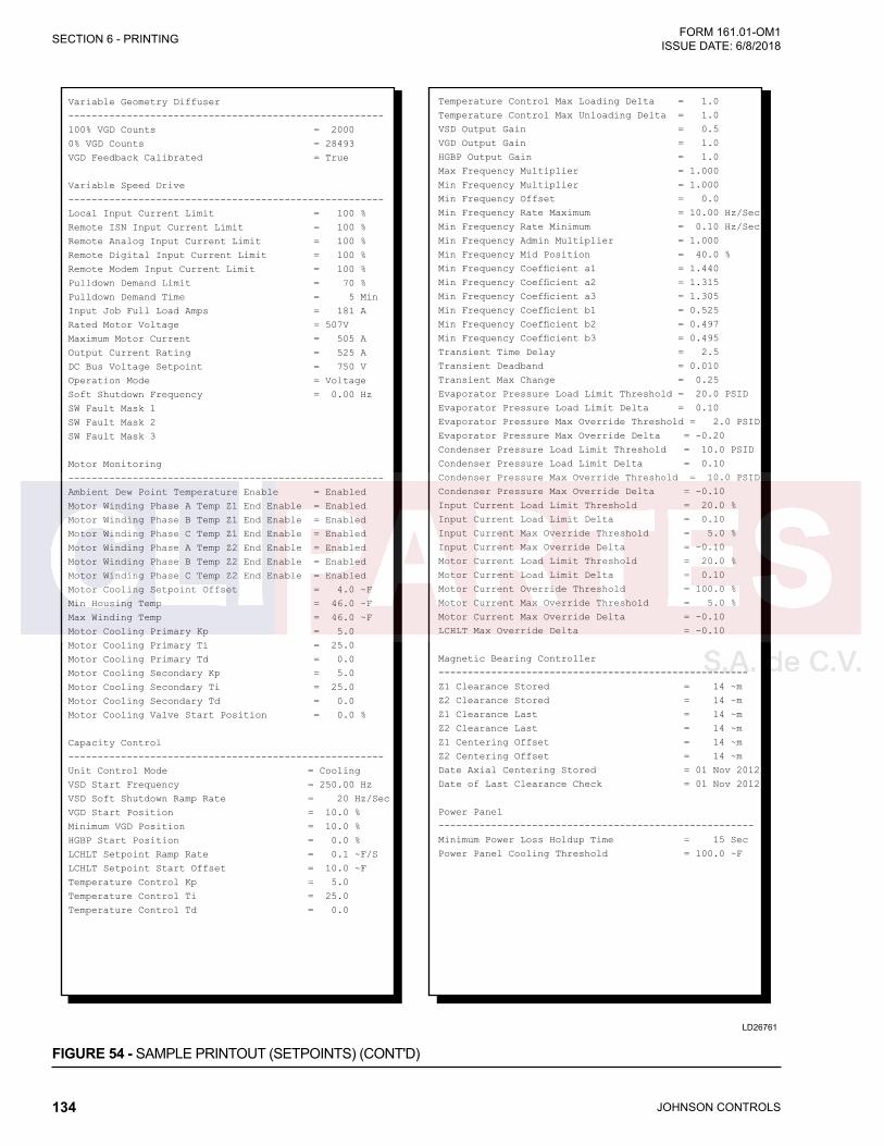
JOHNSON CONTROLS134
FORM 161.01-OM1 ISSUE DATE: 6/8/2018SECTION 6 - PRINTING
FIGURE 54 - SAMPLE PRINTOUT (SETPOINTS) (CONT'D)
LD26761
Variable Geometry Diffuser
------------------------------------------------------
100% VGD Counts = 2000
0% VGD Counts = 28493
VGD Feedback Calibrated = True
Variable Speed Drive
------------------------------------------------------
Local Input Current Limit = 100 %
Remote ISN Input Current Limit = 100 %
Remote Analog Input Current Limit = 100 %
Remote Digital Input Current Limit = 100 %
Remote Modem Input Current Limit = 100 %
Pulldown Demand Limit = 70 %
Pulldown Demand Time = 5 Min
Input Job Full Load Amps = 181 A
Rated Motor Voltage = 507V
Maximum Motor Current = 505 A
Output Current Rating = 525 A
DC Bus Voltage Setpoint = 750 V
Operation Mode = Voltage
Soft Shutdown Frequency = 0.00 Hz
SW Fault Mask 1
SW Fault Mask 2
SW Fault Mask 3
Motor Monitoring
------------------------------------------------------
Ambient Dew Point Temperature Enable = Enabled
Motor Winding Phase A Temp Z1 End Enable = Enabled
Motor Winding Phase B Temp Z1 End Enable = Enabled
Motor Winding Phase C Temp Z1 End Enable = Enabled
Motor Winding Phase A Temp Z2 End Enable = Enabled
Motor Winding Phase B Temp Z2 End Enable = Enabled
Motor Winding Phase C Temp Z2 End Enable = Enabled
Motor Cooling Setpoint Offset = 4.0 ~F
Min Housing Temp = 46.0 ~F
Max Winding Temp = 46.0 ~F
Motor Cooling Primary Kp = 5.0
Motor Cooling Primary Ti = 25.0
Motor Cooling Primary Td = 0.0
Motor Cooling Secondary Kp = 5.0
Motor Cooling Secondary Ti = 25.0
Motor Cooling Secondary Td = 0.0
Motor Cooling Valve Start Position = 0.0 %
Capacity Control
------------------------------------------------------
Unit Control Mode = Cooling
VSD Start Frequency = 250.00 Hz
VSD Soft Shutdown Ramp Rate = 20 Hz/Sec
VGD Start Position = 10.0 %
Minimum VGD Position = 10.0 %
HGBP Start Position = 0.0 %
LCHLT Setpoint Ramp Rate = 0.1 ~F/S
LCHLT Setpoint Start Offset = 10.0 ~F
Temperature Control Kp = 5.0
Temperature Control Ti = 25.0
Temperature Control Td = 0.0
Temperature Control Max Loading Delta = 1.0
Temperature Control Max Unloading Delta = 1.0
VSD Output Gain = 0.5
VGD Output Gain = 1.0
HGBP Output Gain = 1.0
Max Frequency Multiplier = 1.000
Min Frequency Multiplier = 1.000
Min Frequency Offset = 0.0
Min Frequency Rate Maximum = 10.00 Hz/Sec
Min Frequency Rate Minimum = 0.10 Hz/Sec
Min Frequency Admin Multiplier = 1.000
Min Frequency Mid Position = 40.0 %
Transient Time Delay = 2.5
Transient Deadband = 0.010
Transient Max Change = 0.25
Evaporator Pressure Load Limit Threshold = 20.0 PSID
Evaporator Pressure Load Limit Delta = 0.10
Evaporator Pressure Max Override Threshold = 2.0 PSID
Evaporator Pressure Max Override Delta = -0.20
Condenser Pressure Load Limit Threshold = 10.0 PSID
Condenser Pressure Load Limit Delta = 0.10
Condenser Pressure Max Override Threshold = 10.0 PSID
Condenser Pressure Max Override Delta = -0.10
Input Current Load Limit Threshold = 20.0 %
Input Current Load Limit Delta = 0.10
Input Current Max Override Threshold = 5.0 %
Input Current Max Override Delta = -0.10
Motor Current Load Limit Threshold = 20.0 %
Motor Current Load Limit Delta = 0.10
Motor Current Override Threshold = 100.0 %
Motor Current Max Override Threshold = 5.0 %
Motor Current Max Override Delta = -0.10
LCHLT Max Override Delta = -0.10
Magnetic Bearing Controller
-----------------------------------------------------
Z1 Clearance Stored = 14 ~m
Z2 Clearance Stored = 14 ~m
Z1 Clearance Last = 14 ~m
Z2 Clearance Last = 14 ~m
Z1 Centering Offset = 14 ~m
Z2 Centering Offset = 14 ~m
Date Axial Centering Stored = 01 Nov 2012
Date of Last Clearance Check = 01 Nov 2012
Power Panel
------------------------------------------------------
Minimum Power Loss Holdup Time = 15 Sec
Power Panel Cooling Threshold = 100.0 ~F

JOHNSON CONTROLS 135
SECTION 6 - PRINTINGFORM 161.01-OM1 ISSUE DATE: 6/8/2018
6
FIGURE 54 - SAMPLE PRINTOUT (SCHEDULE)
FIGURE 55 - SAMPLE PRINTOUT (SALES ORDER)
LD26762
YORK SCHEDULE
CHILLER ID 3
© 1997 - 1999 YORK INTERNATIONAL CORPORATION
MON 29 MAR 1999 1 27 PM
SCHEDULE = OFF
STANDARD SCHEDULE
---------------------------------------------------------------------------------SUN START = OFF STOP = OFF
MON START = 8:00 AM STOP = 5:00 PM
TUE START = 8:00 AM STOP = 5:00 PM
WED START = 8:00 AM STOP = 5:00 PM
THU START = 8:00 AM STOP = 5:00 PM
FRI START = 8:00 AM STOP = 5:00 PM
SAT START = OFF STOP = OFF
EXCEPTION DAYS
---------------------------------------------------------------------------------02 APR 1999 START = OFF STOP = OFF
13 APR 1999 START = 8:00 AM STOP = 10:00 PM
LD26763
YORK SALES ORDER
YZ ¬CHILLER ID 1
(C) 2010 JOHNSON CONTROLS
MON 01 NOV 2010 9:25:18 AM
ORDER INFORMATION
------------------------------------------------------
COMMISSIONING DATE =
JOB NAME = YORK BUILDING 36 CHILLER 1
SYSTEM MODEL = YZXXXXXX
YORK ORDER NUMBER
UNIT SERIAL NUMBER
COMPRESSOR MODEL
EVAPORATOR MODEL
CONDENSER MODEL
VSD MODEL
NAMEPLATE INFORMATION
------------------------------------------------------
CAPACITY (TONS OR KW)
REFRIGERANT
REFRIG WEIGHT (LBS OR KG)
RPM
INPUT KW
VOLTAGE
PHASES
FREQUENCY
INPUT JOB FLA
MIN CIRCUIT AMPACITY
DESIGN CONDITIONS - EVAPORATOR
------------------------------------------------------
EVAPORATOR PRESSURE DROP (FT OR KPA)
EVAPORATOR FLOW (GPM OR L/S)
EVAPORATOR LEAVING TEMPERATURE (°F OR °C)
EVAPORATOR ENTERING TEMPERATURE (°F OR °C)
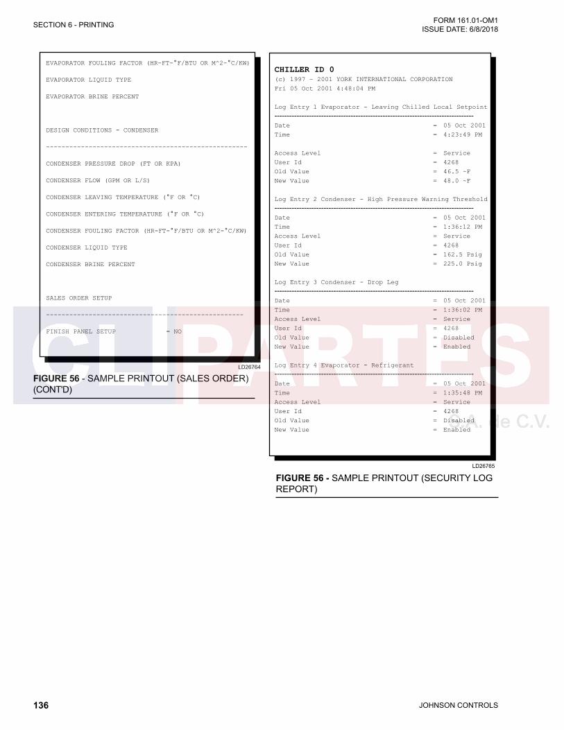
JOHNSON CONTROLS136
FORM 161.01-OM1 ISSUE DATE: 6/8/2018SECTION 6 - PRINTING
FIGURE 56 - SAMPLE PRINTOUT (SALES ORDER) (CONT'D)
FIGURE 56 - SAMPLE PRINTOUT (SECURITY LOG REPORT)
LD26764
EVAPORATOR FOULING FACTOR (HR-FT-°F/BTU OR M^2-°C/KW)
EVAPORATOR LIQUID TYPE
EVAPORATOR BRINE PERCENT
DESIGN CONDITIONS - CONDENSER
----------------------------------------------------
CONDENSER PRESSURE DROP (FT OR KPA)
CONDENSER FLOW (GPM OR L/S)
CONDENSER LEAVING TEMPERATURE (°F OR °C)
CONDENSER ENTERING TEMPERATURE (°F OR °C)
CONDENSER FOULING FACTOR (HR-FT-°F/BTU OR M^2-°C/KW)
CONDENSER LIQUID TYPE
CONDENSER BRINE PERCENT
SALES ORDER SETUP
---------------------------------------------------
FINISH PANEL SETUP = NO
LD26765
CHILLER ID 0(c) 1997 – 2001 YORK INTERNATIONAL CORPORATION
Fri 05 Oct 2001 4:48:04 PM
Log Entry 1 Evaporator - Leaving Chilled Local Setpoint
---------------------------------------------------------------------------------Date = 05 Oct 2001
Time = 4:23:49 PM
Access Level = Service
User Id = 4268
Old Value = 46.5 ~F
New Value = 48.0 ~F
Log Entry 2 Condenser - High Pressure Warning Threshold---------------------------------------------------------------------------------Date = 05 Oct 2001
Time = 1:36:12 PM
Access Level = Service
User Id = 4268
Old Value = 162.5 Psig
New Value = 225.0 Psig
Log Entry 3 Condenser - Drop Leg---------------------------------------------------------------------------------Date = 05 Oct 2001
Time = 1:36:02 PM
Access Level = Service
User Id = 4268
Old Value = Disabled
New Value = Enabled
Log Entry 4 Evaporator - Refrigerant---------------------------------------------------------------------------------Date = 05 Oct 2001
Time = 1:35:48 PM
Access Level = Service
User Id = 4268
Old Value = Disabled
New Value = Enabled
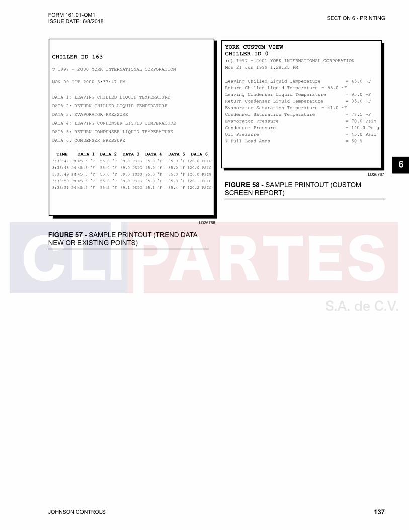
JOHNSON CONTROLS 137
SECTION 6 - PRINTINGFORM 161.01-OM1 ISSUE DATE: 6/8/2018
6LD26767
YORK CUSTOM VIEWCHILLER ID 0(c) 1997 – 2001 YORK INTERNATIONAL CORPORATION
Mon 21 Jun 1999 1:28:25 PM
Leaving Chilled Liquid Temperature = 45.0 ~F
Return Chilled Liquid Temperature = 55.0 ~F
Leaving Condenser Liquid Temperature = 95.0 ~F
Return Condenser Liquid Temperature = 85.0 ~F
Evaporator Saturation Temperature = 41.0 ~F
Condenser Saturation Temperature = 78.5 ~F
Evaporator Pressure = 70.0 Psig
Condenser Pressure = 140.0 Psig
Oil Pressure = 45.0 Psid
% Full Load Amps = 50 %
LD26766
CHILLER ID 163
© 1997 – 2000 YORK INTERNATIONAL CORPORATION
MON 09 OCT 2000 3:33:47 PM
DATA 1: LEAVING CHILLED LIQUID TEMPERATURE
DATA 2: RETURN CHILLED LIQUID TEMPERATURE
DATA 3: EVAPORATOR PRESSURE
DATA 4: LEAVING CONDENSER LIQUID TEMPERATURE
DATA 5: RETURN CONDENSER LIQUID TEMPERATURE
DATA 6: CONDENSER PRESSURE
TIME DATA 1 DATA 2 DATA 3 DATA 4 DATA 5 DATA 6 3:33:47 PM 45.5 °F 55.0 °F 39.0 PSIG 95.0 °F 85.0 °F 120.0 PSIG
3:33:48 PM 45.5 °F 55.0 °F 39.0 PSIG 95.0 °F 85.0 °F 120.0 PSIG
3:33:49 PM 45.5 °F 55.0 °F 39.0 PSIG 95.0 °F 85.0 °F 120.0 PSIG
3:33:50 PM 45.5 °F 55.0 °F 39.0 PSIG 95.0 °F 85.3 °F 120.1 PSIG
3:33:51 PM 45.5 °F 55.2 °F 39.1 PSIG 95.1 °F 85.4 °F 120.2 PSIG
FIGURE 57 - SAMPLE PRINTOUT (TREND DATA NEW OR EXISTING POINTS)
FIGURE 58 - SAMPLE PRINTOUT (CUSTOM SCREEN REPORT)
JOHNSON CONTROLS138
FORM 161.01-OM1 ISSUE DATE: 6/8/2018SECTION 6 - PRINTING
THIS PAGE INTENTIONALLY LEFT BLANK.
JOHNSON CONTROLS 139
SECTION 7 - DECOMMISSIONING, DISMANTLING, AND DISPOSALFORM 161.01-OM1 ISSUE DATE: 6/8/2018
7
SECTION 7 - DECOMMISSIONING, DISMANTLING, AND DISPOSAL
Never release refrigerant to the atmo-sphere when emptying the refrigerating circuits. Suitable retrieval equipment must be used. If reclaimed refrigerant cannot be reused, it must be returned to the manufacturer.
Unless otherwise indicated, the operations described below can be performed by any properly trained main-tenance technician.
1. Isolate all sources of electrical supply to the unit, including any control system supplies switched by the unit. Make sure that all isolation points are secured in the off position.
2. Disconnect and remove the supply cables. For connection points, refer to form 161.01-PW3.
3. Remove all refrigerant from each system into a suitable container, using a refrigerant reclaim or recovery unit. This refrigerant may then be reused, if appropriate, or returned to the manufacturer for disposal. Under NO circumstances should refrig-erant be vented into the atmosphere.
4. Isolate the heat exchangers from the external wa-ter systems and drain that section of the system. If no isolation valves are installed it may be neces-sary to drain the entire system.
• If glycol was used in the water system, or if the system contains chemical additives, dispose of the solution in a suitable and safe manner. Under NO circumstances should any system containing glycol be drained directly into domestic waste or natural water systems.
5. After draining the heat exchangers, disconnect the water lines.
6. Remove the unit in one piece after disconnect-ing. Remove all bolts securing the chiller, and lift the unit using the designated rigging points and equipment with adequate lifting capacity.
Refer to form 161.01-N1 for unit installation instruc-tions, and SECTION 5 - MAINTENANCE for unit weights.
Units, which cannot be removed in one piece after being disconnected must be dismantled in position. Handle each component carefully. Where possible, dis-mantle units in the reverse order of installation.
Make sure that while components are being removed, the remaining parts are adequately supported.
Only use lifting equipment of adequate capacity. See form 161.01-N1 for all lift-ing and rigging.
After removing the unit, dispose of all parts according to local laws and regulations.
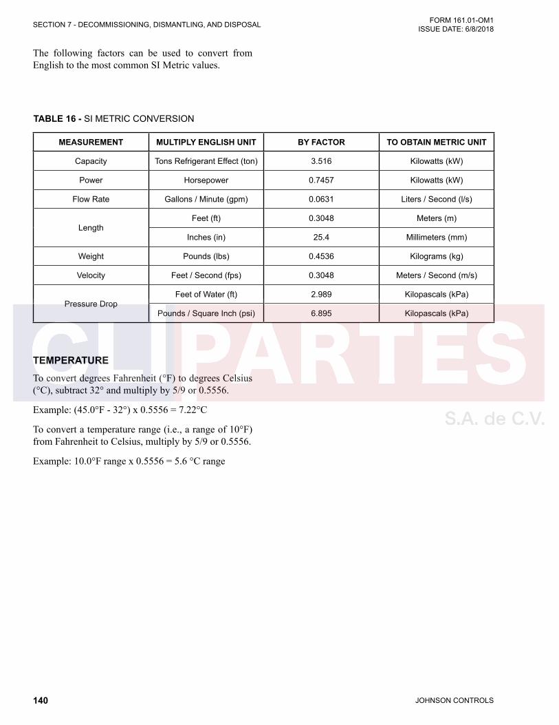
JOHNSON CONTROLS140
FORM 161.01-OM1 ISSUE DATE: 6/8/2018SECTION 7 - DECOMMISSIONING, DISMANTLING, AND DISPOSAL
The following factors can be used to convert from English to the most common SI Metric values.
TEMPERATURETo convert degrees Fahrenheit (°F) to degrees Celsius (°C), subtract 32° and multiply by 5/9 or 0.5556.
Example: (45.0°F - 32°) x 0.5556 = 7.22°C
To convert a temperature range (i.e., a range of 10°F) from Fahrenheit to Celsius, multiply by 5/9 or 0.5556.
Example: 10.0°F range x 0.5556 = 5.6 °C range
TABLE 16 - SI METRIC CONVERSION
MEASUREMENT MULTIPLY ENGLISH UNIT BY FACTOR TO OBTAIN METRIC UNIT
Capacity Tons Refrigerant Effect (ton) 3.516 Kilowatts (kW)
Power Horsepower 0.7457 Kilowatts (kW)
Flow Rate Gallons / Minute (gpm) 0.0631 Liters / Second (l/s)
LengthFeet (ft) 0.3048 Meters (m)
Inches (in) 25.4 Millimeters (mm)
Weight Pounds (lbs) 0.4536 Kilograms (kg)
Velocity Feet / Second (fps) 0.3048 Meters / Second (m/s)
Pressure DropFeet of Water (ft) 2.989 Kilopascals (kPa)
Pounds / Square Inch (psi) 6.895 Kilopascals (kPa)

JOHNSON CONTROLS 141
APPENDIX - MATERIAL SAFETY DATA SHEETSFORM 161.01-OM1 ISSUE DATE: 6/8/2018
APPENDIX - MATERIAL SAFETY DATA SHEETS
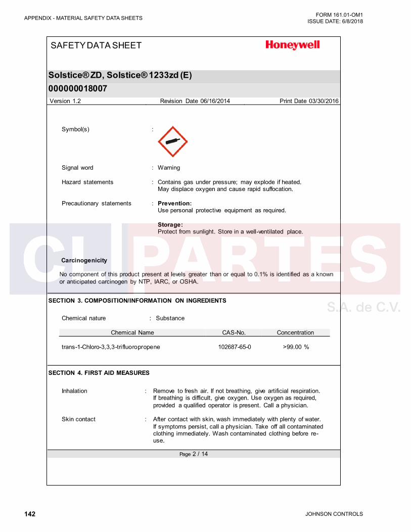
JOHNSON CONTROLS142
FORM 161.01-OM1 ISSUE DATE: 6/8/2018APPENDIX - MATERIAL SAFETY DATA SHEETS
JOHNSON CONTROLS 143
APPENDIX - MATERIAL SAFETY DATA SHEETSFORM 161.01-OM1 ISSUE DATE: 6/8/2018
JOHNSON CONTROLS144
FORM 161.01-OM1 ISSUE DATE: 6/8/2018APPENDIX - MATERIAL SAFETY DATA SHEETS
JOHNSON CONTROLS 145
APPENDIX - MATERIAL SAFETY DATA SHEETSFORM 161.01-OM1 ISSUE DATE: 6/8/2018
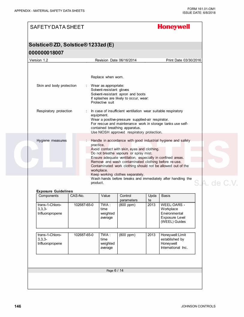
JOHNSON CONTROLS146
FORM 161.01-OM1 ISSUE DATE: 6/8/2018APPENDIX - MATERIAL SAFETY DATA SHEETS
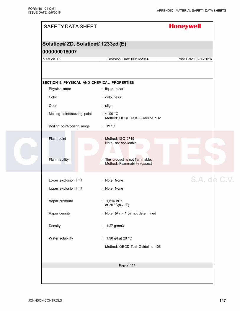
JOHNSON CONTROLS 147
APPENDIX - MATERIAL SAFETY DATA SHEETSFORM 161.01-OM1 ISSUE DATE: 6/8/2018
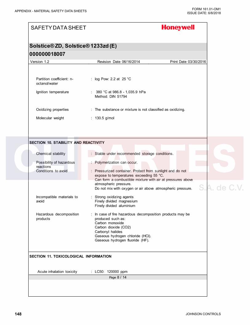
JOHNSON CONTROLS148
FORM 161.01-OM1 ISSUE DATE: 6/8/2018APPENDIX - MATERIAL SAFETY DATA SHEETS

JOHNSON CONTROLS 149
APPENDIX - MATERIAL SAFETY DATA SHEETSFORM 161.01-OM1 ISSUE DATE: 6/8/2018

JOHNSON CONTROLS150
FORM 161.01-OM1 ISSUE DATE: 6/8/2018APPENDIX - MATERIAL SAFETY DATA SHEETS
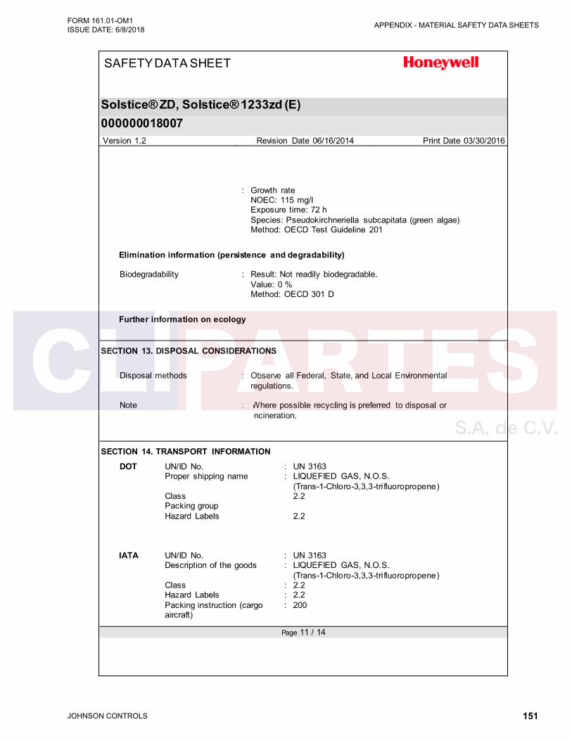
JOHNSON CONTROLS 151
APPENDIX - MATERIAL SAFETY DATA SHEETSFORM 161.01-OM1 ISSUE DATE: 6/8/2018
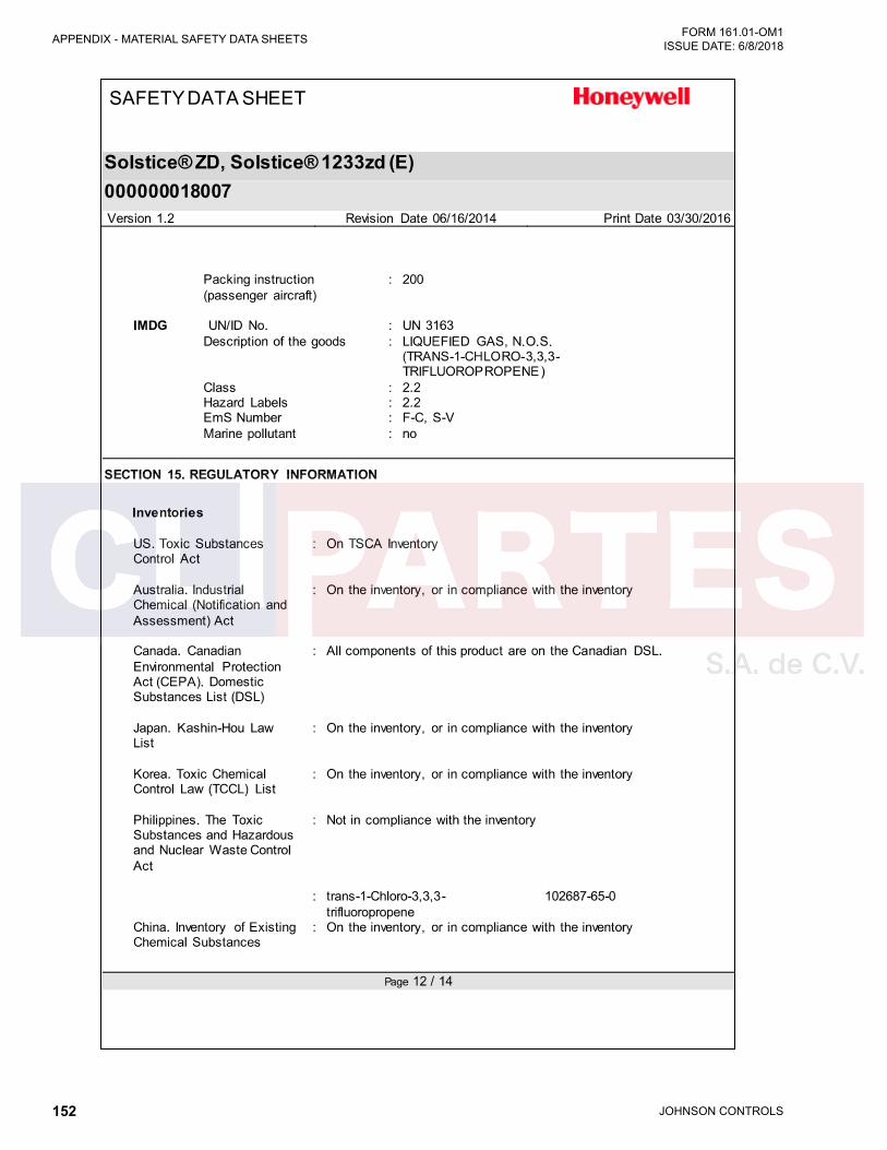
JOHNSON CONTROLS152
FORM 161.01-OM1 ISSUE DATE: 6/8/2018APPENDIX - MATERIAL SAFETY DATA SHEETS
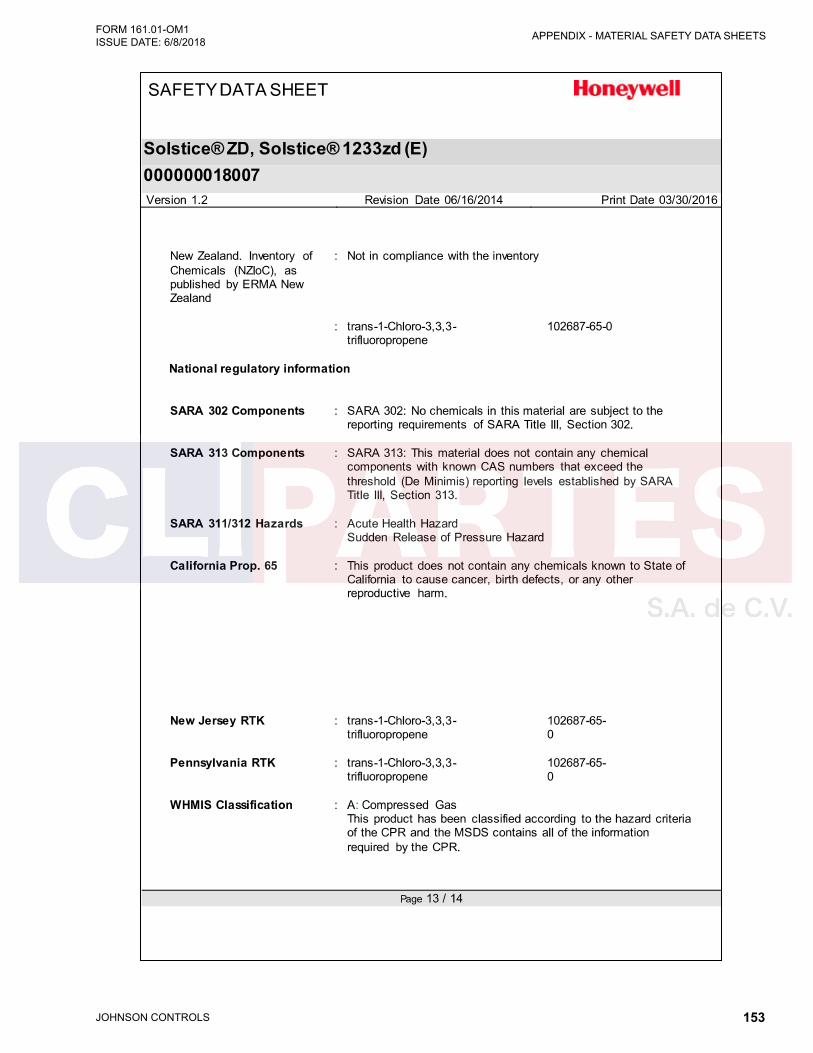
JOHNSON CONTROLS 153
APPENDIX - MATERIAL SAFETY DATA SHEETSFORM 161.01-OM1 ISSUE DATE: 6/8/2018
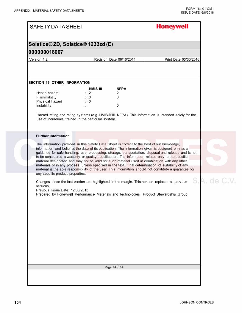
JOHNSON CONTROLS154
FORM 161.01-OM1 ISSUE DATE: 6/8/2018APPENDIX - MATERIAL SAFETY DATA SHEETS
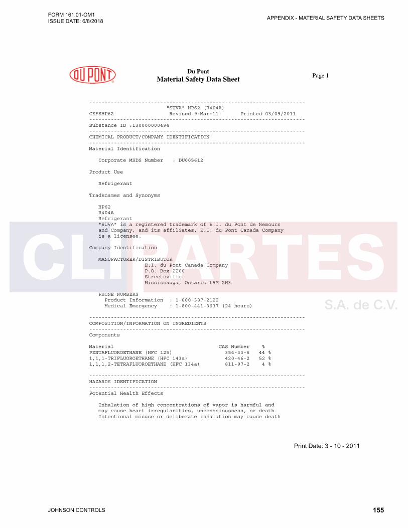
JOHNSON CONTROLS 155
APPENDIX - MATERIAL SAFETY DATA SHEETSFORM 161.01-OM1 ISSUE DATE: 6/8/2018
Du Pont Material Safety Data Sheet
Page 1
---------------------------------------------------------------------- "SUVA" HP62 (R404A) CEFSHP62 Revised 9-Mar-11 Printed 03/09/2011 ---------------------------------------------------------------------- Substance ID :130000000494 ---------------------------------------------------------------------- CHEMICAL PRODUCT/COMPANY IDENTIFICATION ---------------------------------------------------------------------- Material Identification Corporate MSDS Number : DU005612 Product Use Refrigerant Tradenames and Synonyms HP62 R404A Refrigerant "SUVA" is a registered trademark of E.I. du Pont de Nemours and Company, and its affiliates. E.I. du Pont Canada Company is a licensee. Company Identification MANUFACTURER/DISTRIBUTOR E.I. du Pont Canada Company P.O. Box 2200 Streetsville Mississauga, Ontario L5M 2H3 PHONE NUMBERS Product Information : 1-800-387-2122 Medical Emergency : 1-800-441-3637 (24 hours) ---------------------------------------------------------------------- COMPOSITION/INFORMATION ON INGREDIENTS ---------------------------------------------------------------------- Components Material CAS Number % PENTAFLUOROETHANE (HFC 125) 354-33-6 44 % 1,1,1-TRIFLUOROETHANE (HFC 143a) 420-46-2 52 % 1,1,1,2-TETRAFLUOROETHANE (HFC 134a) 811-97-2 4 % ---------------------------------------------------------------------- HAZARDS IDENTIFICATION ---------------------------------------------------------------------- Potential Health Effects Inhalation of high concentrations of vapor is harmful and may cause heart irregularities, unconsciousness, or death. Intentional misuse or deliberate inhalation may cause death
Print Date: 3 - 10 - 2011

JOHNSON CONTROLS156
FORM 161.01-OM1 ISSUE DATE: 6/8/2018APPENDIX - MATERIAL SAFETY DATA SHEETS
CEFSHP62 Du Pont
Material Safety Data Sheet Page 2
Printed on 03/09/2011
without warning. Vapor reduces oxygen available for breathing and is heavier than air. Liquid contact can cause
frostbite. HUMAN HEALTH EFFECTS: Overexposure to the vapors by inhalation may include temporary nervous system depression with anesthetic effects such as dizziness, headache, confusion, incoordination, and loss of consciousness. Higher exposures to the vapors may cause temporary alteration of the heart's electrical activity with irregular pulse, palpitations, or inadequate circulation; or fatality from gross overexposure. Contact with the liquid may cause frostbite. Individuals with preexisting diseases of the central nervous or cardiovascular system may have increased susceptibility to the toxicity of increased exposures. Carcinogenicity Information None of the components present in this material at concentrations equal to or greater than 0.1% are listed by IARC, NTP, OSHA or ACGIH as a carcinogen. ---------------------------------------------------------------------- FIRST AID MEASURES ---------------------------------------------------------------------- First Aid INHALATION If inhaled, immediately remove to fresh air. Keep person calm. If not breathing, give artificial respiration. If breathing is difficult, give oxygen. Call a physician. SKIN CONTACT Flush area with lukewarm water. Do not use hot water. If frostbite has occurred, call a physician. EYE CONTACT In case of contact, immediately flush eyes with plenty of water for at least 15 minutes. Call a physician. INGESTION Not a probable route. However, in case of accidental ingestion, call a physician.
Print Date: 3 - 10 - 2011

JOHNSON CONTROLS 157
APPENDIX - MATERIAL SAFETY DATA SHEETSFORM 161.01-OM1 ISSUE DATE: 6/8/2018
CEFSHP62 Du Pont
Material Safety Data Sheet Page 3
Printed on 03/09/2011
Notes to Physicians THIS MATERIAL MAY MAKE THE HEART MORE SUSCEPTIBLE TO ARRHYTHMIAS. Catecholamines such as adrenaline, and other compounds having similar effects, should be reserved for emergencies and then used only with special caution. ---------------------------------------------------------------------- FIRE FIGHTING MEASURES ---------------------------------------------------------------------- Flammable Properties Flash Point : No flash point Flammable Limits in Air, % by Volume: LEL : None per ASTM E681 UEL : None per ASTM E681 Autoignition: Not determined Fire and Explosion Hazards: Cylinders may rupture under fire conditions. Decomposition may occur. Contact of welding or soldering torch flame with high concentrations of refrigerant can result in visible changes in the size and color of torch flames. This flame effect will only occur in concentrations of product well above the recommended exposure limit, therefore stop all work and ventilate to disperse refrigerant vapors from the work area before using any open flames. R-404A is not flammable in air at temperatures up to 100 deg C (212 deg F) at atmospheric pressure. However, mixtures of R-404A with high concentrations of air at elevated pressure and/or temperature can become combustible in the presence of an ignition source. R-404A can also become combustible in an oxygen enriched environment (oxygen concentrations greater than that in air). Whether a mixture containing R-404A and air, or R-404A in an oxygen enriched atmosphere becomes combustible depends on the inter-relationship of 1) the temperature 2) the pressure, and 3) the proportion of oxygen in the mixture. In general, R-404A should not be allowed to exist with air above atmospheric pressure or at high temperatures; or in an oxygen enriched environment. For example: R-404A should NOT be mixed with air under pressure for leak testing or other purposes. Experimental data have also been reported which indicate combustibility of HFC-134a, a component in this blend, in the presence of chlorine.
Print Date: 3 - 10 - 2011
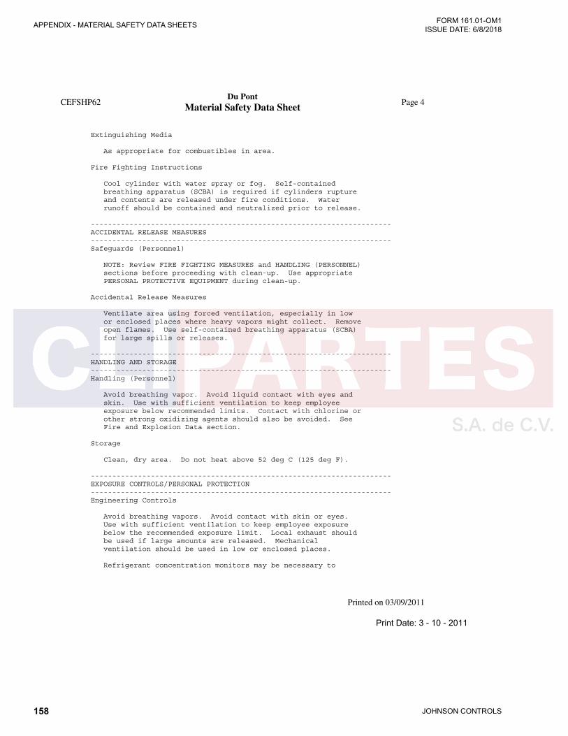
JOHNSON CONTROLS158
FORM 161.01-OM1 ISSUE DATE: 6/8/2018APPENDIX - MATERIAL SAFETY DATA SHEETS
CEFSHP62 Du Pont
Material Safety Data Sheet Page 4
Printed on 03/09/2011
Extinguishing Media As appropriate for combustibles in area. Fire Fighting Instructions Cool cylinder with water spray or fog. Self-contained breathing apparatus (SCBA) is required if cylinders rupture and contents are released under fire conditions. Water runoff should be contained and neutralized prior to release. ---------------------------------------------------------------------- ACCIDENTAL RELEASE MEASURES ---------------------------------------------------------------------- Safeguards (Personnel) NOTE: Review FIRE FIGHTING MEASURES and HANDLING (PERSONNEL) sections before proceeding with clean-up. Use appropriate PERSONAL PROTECTIVE EQUIPMENT during clean-up. Accidental Release Measures Ventilate area using forced ventilation, especially in low or enclosed places where heavy vapors might collect. Remove open flames. Use self-contained breathing apparatus (SCBA) for large spills or releases. ---------------------------------------------------------------------- HANDLING AND STORAGE ---------------------------------------------------------------------- Handling (Personnel) Avoid breathing vapor. Avoid liquid contact with eyes and skin. Use with sufficient ventilation to keep employee exposure below recommended limits. Contact with chlorine or other strong oxidizing agents should also be avoided. See Fire and Explosion Data section. Storage Clean, dry area. Do not heat above 52 deg C (125 deg F). ---------------------------------------------------------------------- EXPOSURE CONTROLS/PERSONAL PROTECTION ---------------------------------------------------------------------- Engineering Controls Avoid breathing vapors. Avoid contact with skin or eyes. Use with sufficient ventilation to keep employee exposure below the recommended exposure limit. Local exhaust should be used if large amounts are released. Mechanical ventilation should be used in low or enclosed places. Refrigerant concentration monitors may be necessary to
Print Date: 3 - 10 - 2011

JOHNSON CONTROLS 159
APPENDIX - MATERIAL SAFETY DATA SHEETSFORM 161.01-OM1 ISSUE DATE: 6/8/2018
CEFSHP62 Du Pont
Material Safety Data Sheet Page 5
Printed on 03/09/2011
determine vapor concentrations in work areas prior to use of torches or other open flames, or if employees are entering enclosed areas. Personal Protective Equipment Impervious gloves should be used to avoid prolonged or repeated exposure. Chemical splash goggles should be available for use as needed to prevent eye contact. Under normal manufacturing conditions, no respiratory protection is required when using this product. Self-contained breathing apparatus (SCBA) is required if a large release occurs. Exposure Guidelines Applicable Exposure Limits PENTAFLUOROETHANE (HFC 125) PEL (OSHA) : None Established TLV (ACGIH) : None Established AEL * (DuPont) : 1000 ppm, 8 & 12 Hr. TWA WEEL (AIHA) : 1000 ppm, 4900 mg/m3, 8 Hr. TWA 1,1,1-TRIFLUOROETHANE (HFC 143a) PEL (OSHA) : None Established TLV (ACGIH) : None Established AEL * (DuPont) : 1000 ppm, 8 & 12 Hr. TWA WEEL (AIHA) : 1000 ppm, 8 Hr. TWA 1,1,1,2-TETRAFLUOROETHANE (HFC 134a) PEL (OSHA) : None Established TLV (ACGIH) : None Established AEL * (DuPont) : 1000 ppm, 8 & 12 Hr. TWA WEEL (AIHA) : 1000 ppm, 8 Hr. TWA * AEL is DuPont's Acceptable Exposure Limit. Where governmentally imposed occupational exposure limits which are lower than the AEL are in effect, such limits shall take precedence. ---------------------------------------------------------------------- PHYSICAL AND CHEMICAL PROPERTIES ---------------------------------------------------------------------- Physical Data Boiling Point : -46.7 C (-52.1 F) Average Vapor Pressure : 182.1 psia at 25 deg C (77 deg F) % Volatiles : 100 WT% Evaporation Rate : (CL4 = 1) Greater than 1 Solubility in Water : Not determined Odor : Slight ethereal Form : Liquefied gas
Print Date: 3 - 10 - 2011
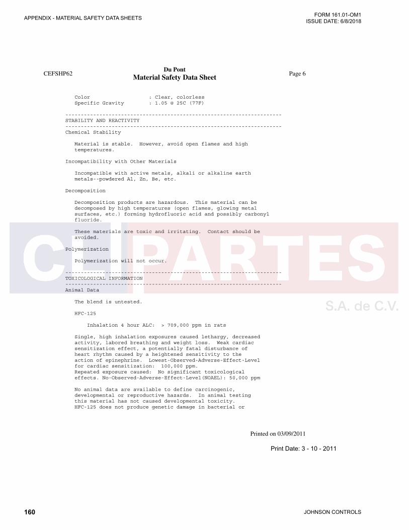
JOHNSON CONTROLS160
FORM 161.01-OM1 ISSUE DATE: 6/8/2018APPENDIX - MATERIAL SAFETY DATA SHEETS
CEFSHP62 Du Pont
Material Safety Data Sheet Page 6
Printed on 03/09/2011
Color : Clear, colorless Specific Gravity : 1.05 @ 25C (77F)
---------------------------------------------------------------------- STABILITY AND REACTIVITY ---------------------------------------------------------------------- Chemical Stability Material is stable. However, avoid open flames and high temperatures. Incompatibility with Other Materials Incompatible with active metals, alkali or alkaline earth metals--powdered Al, Zn, Be, etc. Decomposition Decomposition products are hazardous. This material can be decomposed by high temperatures (open flames, glowing metal surfaces, etc.) forming hydrofluoric acid and possibly carbonyl fluoride. These materials are toxic and irritating. Contact should be avoided. Polymerization Polymerization will not occur. ---------------------------------------------------------------------- TOXICOLOGICAL INFORMATION ---------------------------------------------------------------------- Animal Data The blend is untested. HFC-125 Inhalation 4 hour ALC: > 709,000 ppm in rats Single, high inhalation exposures caused lethargy, decreased activity, labored breathing and weight loss. Weak cardiac sensitization effect, a potentially fatal disturbance of heart rhythm caused by a heightened sensitivity to the action of epinephrine. Lowest-Observed-Adverse-Effect-Level for cardiac sensitization: 100,000 ppm. Repeated exposure caused: No significant toxicological effects. No-Observed-Adverse-Effect-Level(NOAEL): 50,000 ppm No animal data are available to define carcinogenic, developmental or reproductive hazards. In animal testing this material has not caused developmental toxicity. HFC-125 does not produce genetic damage in bacterial or
Print Date: 3 - 10 - 2011

JOHNSON CONTROLS 161
APPENDIX - MATERIAL SAFETY DATA SHEETSFORM 161.01-OM1 ISSUE DATE: 6/8/2018
CEFSHP62 Du Pont
Material Safety Data Sheet Page 7
Printed on 03/09/2011
mammalian cell cultures or when tested in animals (not tested for heritable genetic damage). HFC-134a
Inhalation 4-hour LC50: 567,000 ppm in rats Single exposure caused: Cardiac sensitization, a potentially fatal disturbance of heart rhythm associated with a heightened sensitivity to the action of epinephrine. Lowest-Observed-Adverse-Effect-Level for cardiac sensitization: 75,000 ppm. Single exposure caused: Lethargy. Narcosis. Increased respiratory rates. These effects were temporary. Single exposure to near lethal doses caused: Pulmonary edema. Repeated exposure caused: Increased adrenals, liver, spleen weight. Decreased uterine, prostate weight. Repeated dosing of higher concentrations caused: the following temporary effects - Tremors. Incoordination. CARCINOGENIC, DEVELOPMENTAL, REPRODUCTIVE,MUTAGENIC EFFECTS: In a two-year inhalation study, HFC-134a, at a concentration of 50,000 ppm, produced an increase in late-occurring benign testicular tumors, testicular hyperplasia and testicular weight. The no-effect-level for this study was 10,000 ppm. Animal data show slight fetotoxicity but only at exposure levels producing other toxic effects in the adult animal. Reproductive data on male mice show: No change in reproductive performance. Tests have shown that this material does not cause genetic damage in bacterial or mammalian cell cultures, or in animals. In animal testing, this material has not caused permanent genetic damage in reproductive cells of mammals (has not produced heritable genetic damage). HFC-143a Inhalation 4-hour LC50: >540,000 ppm in rats Single exposures by inhalation to 500,000 ppm caused anesthesia but no mortality at 540,000 ppm. Cardiac sensitization occurred in dogs at 300,000 ppm following an intravenous challenge with epinephrine. Two, 4-week inhalation have been conducted. In the first study, pathological changes in the testes were observed at all exposure concentrations; no effects were observed in females. The testicular effect was considered related to the method used to expose the rats to HFC-143a. In the second study using the same exposure concentrations, no effects were noted in males at any concentration. Data from a 90-day study revealed no effects in male or female rats at exposures up to 40,000 ppm. Long-term exposure caused
Print Date: 3 - 10 - 2011
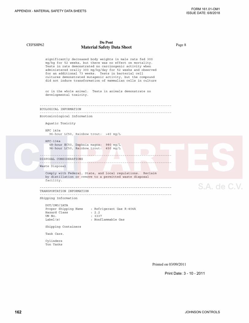
JOHNSON CONTROLS162
FORM 161.01-OM1 ISSUE DATE: 6/8/2018APPENDIX - MATERIAL SAFETY DATA SHEETS
CEFSHP62 Du Pont
Material Safety Data Sheet Page 8
Printed on 03/09/2011
significantly decreased body weights in male rats fed 300 mg/kg for 52 weeks, but there was no effect on mortality. Tests in rats demonstrated no carcinogenic activity when administered orally 300 mg/kg/day for 52 weeks and observed for an additional 73 weeks. Tests in bacterial cell cultures demonstrated mutagenic activity, but the compound did not induce transformation of mammalian cells in culture
or in the whole animal. Tests in animals demonstrate no developmental toxicity. ---------------------------------------------------------------------- ECOLOGICAL INFORMATION ---------------------------------------------------------------------- Ecotoxicological Information Aquatic Toxicity HFC 143a 96-hour LC50, Rainbow trout: >40 mg/L HFC-134a 48-hour EC50, Daphnia magna: 980 mg/L 96-hour LC50, Rainbow trout: 450 mg/L ---------------------------------------------------------------------- DISPOSAL CONSIDERATIONS ---------------------------------------------------------------------- Waste Disposal Comply with Federal, State, and local regulations. Reclaim by distillation or remove to a permitted waste disposal facility. ---------------------------------------------------------------------- TRANSPORTATION INFORMATION ---------------------------------------------------------------------- Shipping Information DOT/IMO/IATA Proper Shipping Name : Refrigerant Gas R-404A Hazard Class : 2.2 UN No. : 3337 Label(s) : Nonflammable Gas Shipping Containers Tank Cars. Cylinders Ton Tanks
Print Date: 3 - 10 - 2011
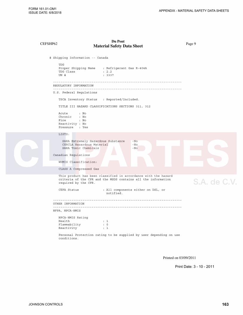
JOHNSON CONTROLS 163
APPENDIX - MATERIAL SAFETY DATA SHEETSFORM 161.01-OM1 ISSUE DATE: 6/8/2018
CEFSHP62 Du Pont
Material Safety Data Sheet Page 9
Printed on 03/09/2011
# Shipping Information -- Canada TDG Proper Shipping Name : Refrigerant Gas R-404A TDG Class : 2.2 UN # : 3337 ---------------------------------------------------------------------- REGULATORY INFORMATION ---------------------------------------------------------------------- U.S. Federal Regulations TSCA Inventory Status : Reported/Included. TITLE III HAZARD CLASSIFICATIONS SECTIONS 311, 312 Acute : No Chronic : No Fire : No Reactivity : No Pressure : Yes LISTS: SARA Extremely Hazardous Substance -No CERCLA Hazardous Material -No SARA Toxic Chemicals -No Canadian Regulations WHMIS Classification: CLASS A Compressed Gas This product has been classified in accordance with the hazard criteria of the CPR and the MSDS contains all the information required by the CPR. CEPA Status : All components either on DSL, or notified. ---------------------------------------------------------------------- OTHER INFORMATION ---------------------------------------------------------------------- NFPA, NPCA-HMIS NPCA-HMIS Rating Health : 1 Flammability : 0 Reactivity : 1 Personal Protection rating to be supplied by user depending on use conditions.
Print Date: 3 - 10 - 2011
JOHNSON CONTROLS164
FORM 161.01-OM1 ISSUE DATE: 6/8/2018APPENDIX - MATERIAL SAFETY DATA SHEETS
CEFSHP62 Du Pont
Material Safety Data Sheet Page 10
Printed on 03/09/2011
---------------------------------------------------------------------- The data in this Material Safety Data Sheet relates only to the specific material designated herein and does not relate to use in combination with any other material or in any process. Responsibility for MSDS -----------------------
(Continued) FLUOROPRODUCTS E.I. E.I. du Pont Canada Company Company Box 2200, Streetsville Mississauga, Ontario, L5M 2H3 (905) 821-3300. # Indicates updated section. End of MSDS
Print Date: 3 - 10 - 2011

JOHNSON CONTROLS 165
APPENDIX - MATERIAL SAFETY DATA SHEETSFORM 161.01-OM1 ISSUE DATE: 6/8/2018
Page 1 of 5
Safety Data Sheet
Solid State Starter / VSD Coolant
Product name Solid State Starter / VSD Coolant Description Aqueous Heat Transfer Solution Product class Closed System Manufacturer’s address 201 Burch Drive
Moon Township, PA 15108 Telephone numbers
Manufacturers Phone Number
(412) 262-4827 Emergency Telephone INFOTRAC 800-535-5053
Hazard classification Not hazardous pursuant to 29 CFR 1910.1200. Signal word None Hazard statements None Pictograms of related hazards None Precautionary statements Prevention
Read label before use. Wash skin thoroughly after handling. Wear protective gloves, protective clothing, eye protection, and face protection.
Response IF SWALLOWED: Contact a POISON CENTER or health care provider if you feel unwell. IF ON SKIN: Wash with soap and water.
Storage Store in a well-ventilated place. Keep container tightly closed. Keep out of direct sunlight.
Disposal Dispose of contents and container in accordance with local, state, and federal regulations.
Chemical Name CAS # Weight % Non-hazardous substances Proprietary 100
2. HAZARDS IDENTIFICATION
3. COMPOSITION/INFORMATION ON INGREDIENTS
1. IDENTIFICATION
Manufactured For: Johnson Controls Inc. (York International) For emergency assistance, call: INFOTRAC at 1-800-535-5053
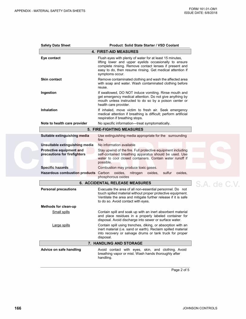
JOHNSON CONTROLS166
FORM 161.01-OM1 ISSUE DATE: 6/8/2018APPENDIX - MATERIAL SAFETY DATA SHEETS
Page 2 of 5
Safety Data Sheet Product: Solid State Starter / VSD Coolant
Eye contact Flush eyes with plenty of water for at least 15 minutes, lifting lower and upper eyelids occasionally to ensure complete rinsing. Remove contact lenses if present and easy to do, then resume rinsing. Get medical attention if symptoms occur.
Skin contact Remove contaminated clothing and wash the affected area with soap and water. Wash contaminated clothing before reuse.
Ingestion If swallowed, DO NOT induce vomiting. Rinse mouth and get emergency medical attention. Do not give anything by mouth unless instructed to do so by a poison center or health care provider.
Inhalation If inhaled, move victim to fresh air. Seek emergency medical attention if breathing is difficult; perform artificial respiration if breathing stops.
Note to health care provider No specific information—treat symptomatically.
Suitable extinguishing media Use extinguishing media appropriate for the surrounding fire.
Unsuitable extinguishing media No information available Protective equipment and precautions for firefighters
Stay upwind of the fire. Full protective equipment including self-contained breathing apparatus should be used. Use water to cool closed containers. Contain water runoff if possible.
Specific hazards Combustion may produce toxic gases. Hazardous combustion products Carbon oxides, nitrogen oxides, sulfur oxides,
phosphorous oxides
Personal precautions Evacuate the area of all non-essential personnel. Do not touch spilled material without proper protective equipment. Ventilate the area and mitigate further release if it is safe to do so. Avoid contact with eyes.
Methods for clean-up Small spills Contain spill and soak up with an inert absorbent material
and place residues in a properly labeled container for disposal. Avoid discharge into sewer or surface water.
Large spills Contain spill using trenches, diking, or absorption with an inert material (i.e. sand or earth). Reclaim spilled material into recovery or salvage drums or tank truck for proper disposal.
Advice on safe handling Avoid contact with eyes, skin, and clothing. Avoid breathing vapor or mist. Wash hands thoroughly after handling.
5. FIRE-FIGHTING MEASURES
6. ACCIDENTAL RELEASE MEASURES
7. HANDLING AND STORAGE
4. FIRST-AID MEASURES

JOHNSON CONTROLS 167
APPENDIX - MATERIAL SAFETY DATA SHEETSFORM 161.01-OM1 ISSUE DATE: 6/8/2018
3
Page 3 of 5
Safety Data Sheet Product: Solid State Starter / VSD Coolant
Storage conditions Store in a cool, dry, well-ventilated area away from incompatible materials. Keep containers closed when not in use.
Suitable materials of construction
No information available
Unsuitable materials of construction
No information available
Eye/face protection Chemical splash goggles Skin protection Chemical-resistant gloves and body-covering clothing Respiratory protection Respiratory protection is not normally required. A
respirator is recommended if significant mists, vapors, or aerosols are generated.
Engineering controls Adequate ventilation, eye-wash station, and emergency shower
General hygiene considerations Do not eat, drink, or smoke while handling this product.
Chemical Name OSHA PEL ACGIH TLV Non-hazardous substances None established None established
pH 7.5-8.0 Appearance Blue, Clear liquid Odor Mild Odor Threshold No information available Melting/freezing point No information available Initial boiling point/boiling range
No information available
Flash point No information available Evaporation rate No information available Flammability (solid, gas) No information available Upper/lower flammability or explosive limits
No information available
Vapor pressure No information available Vapor density No information available VOC content No information available Specific gravity 0.960-1.040 Solubility Complete Partition coefficient
n-octanol/water No information available
Auto-ignition temperature No information available Decomposition temperature No information available Viscosity No information available
8. EXPOSURE CONTROLS/PERSONAL PROTECTION
9. PHYSICAL AND CHEMICAL PROPERTIES
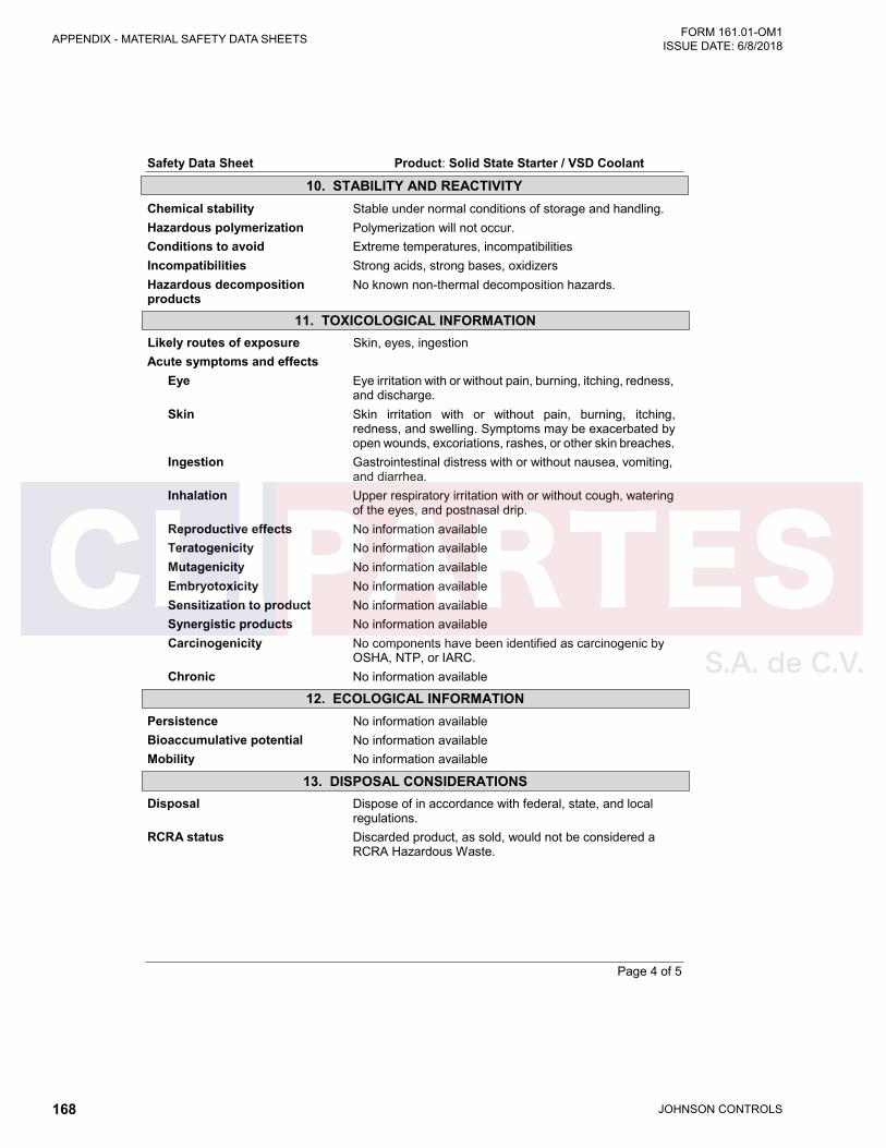
JOHNSON CONTROLS168
FORM 161.01-OM1 ISSUE DATE: 6/8/2018APPENDIX - MATERIAL SAFETY DATA SHEETS
Page 4 of 5
Safety Data Sheet Product: Solid State Starter / VSD Coolant
Chemical stability Stable under normal conditions of storage and handling. Hazardous polymerization Polymerization will not occur. Conditions to avoid Extreme temperatures, incompatibilities Incompatibilities Strong acids, strong bases, oxidizers Hazardous decomposition products
No known non-thermal decomposition hazards.
Likely routes of exposure Skin, eyes, ingestion Acute symptoms and effects
Eye Eye irritation with or without pain, burning, itching, redness, and discharge.
Skin Skin irritation with or without pain, burning, itching, redness, and swelling. Symptoms may be exacerbated by open wounds, excoriations, rashes, or other skin breaches.
Ingestion Gastrointestinal distress with or without nausea, vomiting, and diarrhea.
Inhalation Upper respiratory irritation with or without cough, watering of the eyes, and postnasal drip.
Reproductive effects No information available Teratogenicity No information available Mutagenicity No information available Embryotoxicity No information available Sensitization to product No information available Synergistic products No information available Carcinogenicity No components have been identified as carcinogenic by
OSHA, NTP, or IARC. Chronic No information available
Persistence No information available Bioaccumulative potential No information available Mobility No information available
Disposal Dispose of in accordance with federal, state, and local regulations.
RCRA status Discarded product, as sold, would not be considered a RCRA Hazardous Waste.
11. TOXICOLOGICAL INFORMATION
12. ECOLOGICAL INFORMATION
13. DISPOSAL CONSIDERATIONS
10. STABILITY AND REACTIVITY

JOHNSON CONTROLS 169
APPENDIX - MATERIAL SAFETY DATA SHEETSFORM 161.01-OM1 ISSUE DATE: 6/8/2018
3
Page 5 of 5
Safety Data Sheet Product: Solid State Starter / VSD Coolant
14. TRANSPORT INFORMATION
US Department of Transportation (DOT) UN Number Proper shipping name Not regulated Primary hazard class/division Secondary hazard Packing group Label
OSHA Hazard Communication Status
Not hazardous pursuant to 29 CFR 1910.1200.
EPA Registration Number Not applicable TSCA The ingredients of this product are listed on the Toxic
Substances Control Act (TSCA) Chemical Substances Inventory.
CERCLA EPA Hazardous Substances (40 CFR 302)
Chemical Name Reportable Quantity (RQ) Non-hazardous substances None
SARA Title III (Sections 302, 311, 312, and 313) Section 302 Extremely Hazardous Substances (40 CFR 355)
Chemical Name CAS# RQ TPQ None
Section 311 and 312 Health and Physical Hazards Immediate Delayed Fire Pressure Reactivity
No No No No No
Section 313 Toxic Chemicals (40 CFR 372) Chemical Name CAS Number Percent by Weight
None
HMIS Ratings Health—0; Flammability—0; Reactivity—0 NFPA Ratings Health—0; Flammability—0; Reactivity—0 HMIS/NFPA Rating Scale Minimal—0; Slight—1; Moderate—2; Serious—3; Severe—4 SDS Issue Date 10/14/2016 Version 1 The information provided in this Safety Data Sheet is correct to the best of our knowledge, information, and belief at the date of its publication. The information given is designed only as guidance for safe handling, use, processing, storage, transportation, disposal, and release and is not to be considered a warranty or quality specification. The information relates only to the specific material designated and may not be valid for such material used in combination with any other materials or in any process, unless specified in the text.
15. REGULATORY INFORMATION
16. OTHER INFORMATION

5000 Renaissance Drive, New Freedom, Pennsylvania USA 17349 800-861-1001 Subject to change without notice. Printed in USACopyright © by Johnson Controls 2018 www.johnsoncontrols.com ALL RIGHTS RESERVEDForm 161.01-OM1 (618)Issue Date: June 8, 2018 New Release