za.usembassy.gov · web viewfacilities management statement of work the us embassy will install...
TRANSCRIPT

Facilities
Page | 1

ManagementStatement of Work
The US Embassy will install MonTICK generator Monitors to all their Generator sets at their residences to monitor functions and the status of the standby Generators, this will ensure that the Generators are functional at all times to ensure the security and safety of the occupants during power outages.
Vendor to Supply the Following for All Residential Generators:
i. GSM Dialer MonTICK generator systemii. Field Wiring Harness for MonTICKiii. Voltage Monitor for MonTICKiv. Remote start relay for MonTICKv. Magnetic Base GSM Antenna for MonTICK
US Embassy to Supply
1. Contract SIM cards for the followingi. SIM Card for each Generatorii. SIM Card for Stand-alone PC (if needed)
2. One Stand-alone Office PC with general internet access
i. Microsoft Windows 7ii. Microsoft Office Suite 7iii. USB ports and CD Rom to be enabled
MonTICK GSM Dialer Functions:
1. The MonTICK generator monitor will send status updates to a Gentick server regularly (+- every 7minutes) the information will include the following
i. Battery voltageii. Fuel Leveliii. Run/Stopped statusiv. Time and datev. Runtime since startvi. Common Alarm statusvii. GSM signal strength indicationviii. Incomer phase voltages when using a Voltage Monitor unit
Page | 2

2. The Dialer must have a function to notify post when there is any change in status for the generator with the following.i. Incomer phase voltage conditions (Eg power fail)ii. Run/Stop Statusiii. Fuel Leveliv. Battery Voltage
Vendor to Provide the Following Service
1. Train Embassy personnel on the installation and usage of the MonTICK unit2. Train Embassy personnel on the usage of the web-based interface
US Embassy to Provide the Following Service
1. Install the following as per Installation Guide/ Training provided.i. MonTICK connection harnessii. Start Relaysiii. Voltage Monitoring Unitsiv. GSM Antenna’sv. All wiring and terminations to be done as per local code (SANS10142)
GSM Dialer Installation Guide
This guide is a supplemental to the original GSM Dialer manual (Attached to SOW) as the vendor manual is too generic, we have assembled this document with all our custom connections and configurations that are designed to meet US Embassy Generator specifications and requirements.
Index
1. Fuel probe connections (Pages 6&7)2. Connections for the GSM Dialer (Page 8&9)3. Start/Stop Relay connections (Page 9)4. Montick Dialer Input (Power)/Outputs (Fig 1)5. Control Panel (Fig 2)6. 50mm Trunking (Fig 3)7. Wiring Harness (Fig 4)8. Fuel Level Sender Wires (Fig 5)9. Fuel Sender (Fig 6)10.Remote Start/Stop Relay Output Diagram (Fig 9/10)
Fig 1
Page | 3

Fuel probe connections:
1. Open the bottom panel by removing the four M6 screws ends removes the panel cover carefully.
2. Open the panel containing the NEXYS controller by removing the two M6 screws on the top of the panel cover.
Fig 2
Page | 4
Outputs
Inputs/Power
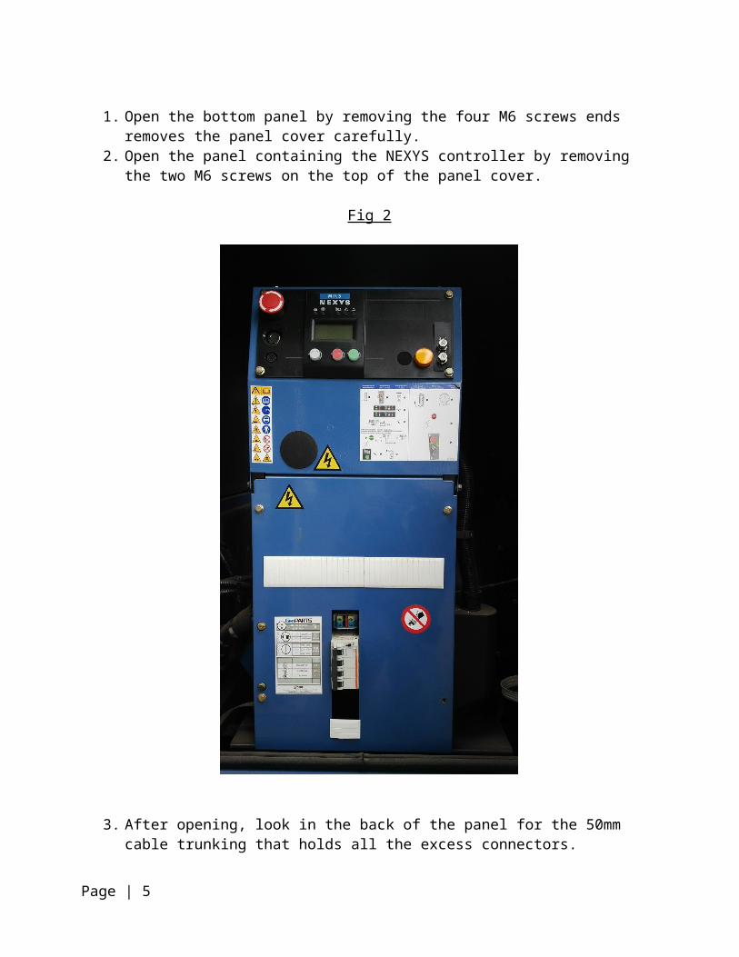
3. After opening, look in the back of the panel for the 50mm cable trunking that holds all the excess connectors.
Fig 3
Page | 5

Fig 4
4. Cut the two wires numbered wires (178) (Fuel Sender Wires) from the Jack (Fig 5)5. Splice the two “178” wire together on the one side of an Insulated ferrule.6. Splice a 1.5mm² automotive wire to the other side of the Insulated Ferrule.
7. Connect the wire to Output Pin 1 of the Dialer. (The original manual shows the pin as “fuel gauge harness to fuel probe”)
Fig 5
Page | 6
Wiring Harness Jack
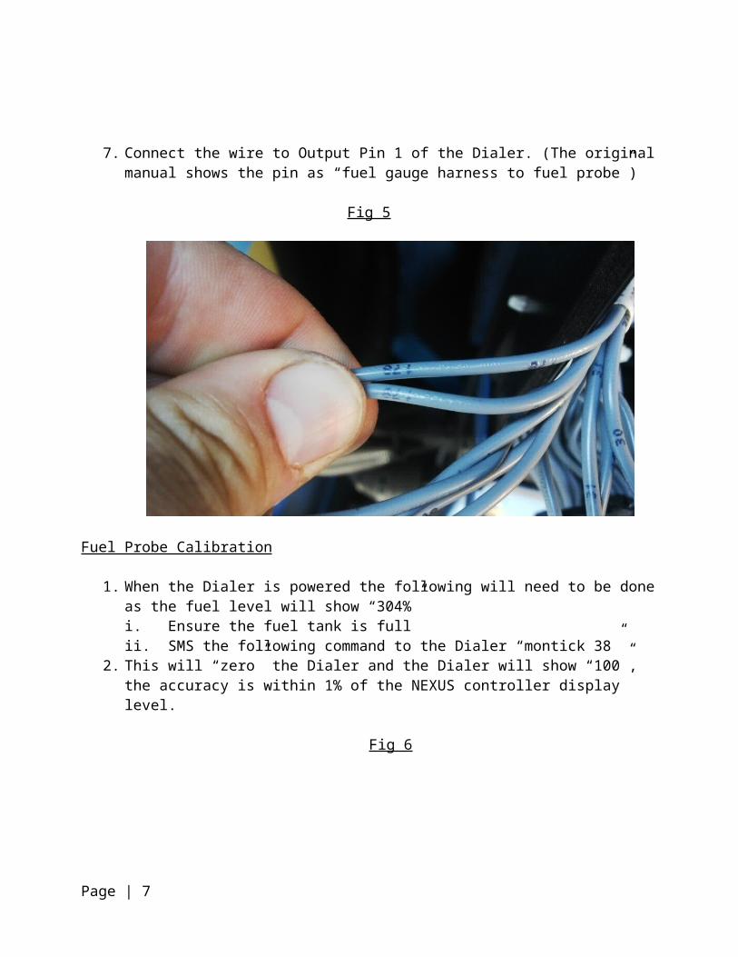
Fuel Probe Calibration
1. When the Dialer is powered the following will need to be done as the fuel level will show “304%”i. Ensure the fuel tank is fullii. SMS the following command to the Dialer “montick 38”
2. This will “zero” the Dialer and the Dialer will show “100”, the accuracy is within 1% of the NEXUS controller display level.
Fig 6
Fig 7
Page | 7

Fig 8
5NB – Inputs 1,4,5,6 must be bridged with input 8 if the Dialer is installed without a Voltage and ATS Circuit Breaker Monitor.
Fig 9
Page | 8
Input Pins 1 2 3 4 5 6 7 8
Circuit Breaker Monitor N/C
Voltage Monitor Three Phase Input 400V / 12v Input to Dialer

Fig 10
Start-Stop relays connection diagram
BIN/V BIN/V
Start relay Stop relay
ATS Startcable from ATS
Remote Start/Stop Relays
1. Connect the start/stop relays supplied (Dialer) to the BIN/V terminals already supplied with the Generator (Fig 10)
NB – any additional technical data or wiring diagrams will be found in the Vendor User Manual and Wiring Guide Supplied.
End of SOW
Page | 9
Not Used
Remote Stop
Remote Start