zetron model 30 worldpatch with selcall instruction … device must not be installed on...
TRANSCRIPT
ZETRON
Model 30 Worldpatch with SelcallInstruction Manual
Part No. 025-9431B
Please check for change information at the begining of this manual.
Copyright © 1991 - 2000 by Zetron, Inc.All Rights Reserved

Table of Contents
CHANGE INFORMATIONWARRANTY
1. INTRODUCTIONINTRODUCTION .............................................................. 1-1FEATURES....................................................................... 1-1
2. SPECIFICATIONSGENERAL SPECIFICATIONS ......................................... 2-1TELEPHONE INTERFACE SPECIFICATIONS ............... 2-1RADIO INTERFACE SPECIFICATIONS.......................... 2-1ADDITIONAL SPECIFICATIONS..................................... 2-2PAGING FORMATS ......................................................... 2-2
3. OPERATIONOVERVIEW ...................................................................... 3-1BASIC CALL TYPES ........................................................ 3-1
Phone-to-Mobile Calls ................................................. 3-1Mobile-to-Phone Calls ................................................. 3-2Mobile-to-Mobile Calls................................................. 3-2Once a Call is in Progress........................................... 3-2Remote Programming Access .................................... 3-3
MODEL 30 FEATURES.................................................... 3-3DTMF or Pulse Dial Regeneration .............................. 3-3Toll Restriction............................................................. 3-4Call Limit Timer ........................................................... 3-4Mobile Activity Time .................................................... 3-4Courtesy Tone............................................................. 3-4Repeat Enable............................................................. 3-4Interconnect “Security” ................................................ 3-4Direct to Air.................................................................. 3-5Autodial........................................................................ 3-5Hook-Flash .................................................................. 3-5Non-DTMF Access to Phone Line............................... 3-5Auxiliary Output Control .............................................. 3-5Call Alert ...................................................................... 3-6Dual Function Connect Button .................................... 3-6
SIMPLEX OPERATION.................................................... 3-6Simplex Modes............................................................ 3-6Simplex Timers............................................................ 3-7
Table of Contents(Continued)
OPTIONS.......................................................................... 3-8
4. PROGRAMMINGPROGRAM MODE ACCESS ........................................... 4-1ENTERING A PROGRAM COMMAND............................ 4-1PROGRAMMING COMMANDS ....................................... 4-2
Access and Disconnect Codes ................................... 4-2Mobile-to-Phone Pulse or DTMF Dialing..................... 4-3Number of Rings-to-Answer........................................ 4-3Single Digit Access Code Validation ........................... 4-3Dial Regeneration Timeout Timer ............................... 4-3Hook Flash .................................................................. 4-4Call Waiting Alert ......................................................... 4-4Limit Phone Access to Autodials................................. 4-4Toll Restrict Digits ....................................................... 4-4Ringout Mode .............................................................. 4-4Optional Security Code for Direct to Air ...................... 4-5Repeat Audio Control .................................................. 4-5Call Answer Mode ....................................................... 4-5Morse Code Station ID ................................................ 4-5Interconnect Courtesy Tones ...................................... 4-6Half-Privacy Mode ....................................................... 4-6Call Limit Timer ........................................................... 4-7Mobile Activity Timer ................................................... 4-7Set Operating Mode .................................................... 4-7Sample VOX Before Issuing Dial Tone ....................... 4-8Select Paging Format.................................................. 4-8Two-Tone Paging Parameters .................................... 4-8DTMF Paging Parameters........................................... 4-9Mobile-to-Mobile Paging.............................................. 4-9Autodial Numbers........................................................ 4-9Dial Tone Disconnect .................................................. 4-10Non-DTMF Mobile Access .......................................... 4-10Dual Function Connect Button .................................... 4-10Multiple Second Dial Tone .......................................... 4-10Repeat Courtesy Tone ................................................ 4-11Simplex Sample Rate.................................................. 4-11VOX Hold Time ........................................................... 4-11Automatic Sample Window Setup............................... 4-11
Table of Contents(Continued)
COR Hold Time ........................................................... 4-12Busy Tone Detector..................................................... 4-12PL Strip Output ............................................................ 4-12Auxiliary Output Control .............................................. 4-12Program Access Code ................................................ 4-13Reset All Parameters to Factory Default..................... 4-13Installation Tests ......................................................... 4-13Exit Program Mode...................................................... 4-13
TWO-TONE TABLES ....................................................... 4-14Two-Tone Timing ........................................................ 4-14Two-Tone Tone Groups .............................................. 4-14Two-Tone Code Plans................................................. 4-16
5. INSTALLATIONINSTALLATION WARNING.............................................. 5-1GENERAL......................................................................... 5-1EQUIPMENT REQUIRED FOR INSTALLATION............. 5-1INSTALLATION PROCEDURE........................................ 5-1TEST AND ADJUSTMENTS / INITIAL TURN-ON ........... 5-2OPTIONAL DIGITAL VOICE DELAY ............................... 5-5INSTALLING THE SELCALL OPTION............................. 5-6
6. REPAIRIN CASE OF DIFFICULTY ............................................... 6-1TROUBLESHOOTING ..................................................... 6-1
COR and Squelch Problems ....................................... 6-1Unreliable Dialing or Misdialed Numbers.................... 6-1Unable to Access Dial Tone or Answer a Call ............ 6-2Intermittently Disconnecting During a Call .................. 6-2
MODEL 30 CONTROL BOARD (702-9321K) .................. 6-3Parts List...................................................................... 6-3Schematic.................................................................... 6-5Silkscreen.................................................................... 6-8
7. PROGRAMMING LOG AND QUICK REFERENCEPROGRAMMING.............................................................. 7-1
Programming Example................................................ 7-1PROGRAMMING LOG AND QUICK REFERENCE ........ 7-2AUTODIAL PROGRAMMING LOG.................................. 7-6

Table of Contents(Continued)
WARRANTYZetron’s warranty is published in the current Zetron United States Price Book.
LIMITATION OF LIABILITYZetron makes no representation with respect to the contents of this documentand/or the contents, performance, and function of any accompanying softwareand specifically disclaims any warranties, expressed or implied, as tomerchantability, fitness for purpose sold, description, or quality.
Further, Zetron reserves the right to revise this document or the accompanyingsoftware and to make changes in it from time to time without obligation to notifyany person or organization of such revisions or changes.
This document and any accompanying software are provided “as is.” Zetron shallnot under any circumstances be responsible for any indirect, special, incidental,or consequential damages or losses to the buyer or any third party arising out ofor connected with the buyer’s purchase and use of Zetron’s products or services.
COPYRIGHTThis publication is protected by copyright by Zetron, Inc. and all rights arereserved worldwide. This publication may not, in whole or in part, be copied,photocopied, reproduced, translated, or reduced to any electronic medium ormachine-readable form without prior written consent from Zetron, Inc.
The software in this product is protected by copyright by Zetron, Inc. andremains the property of Zetron, Inc. Reproduction, duplication, or disclosure isnot permitted without prior written consent of Zetron, Inc.
TRADEMARKSZetron is a registered trademark of Zetron, Inc.
All other product names in this document are trademarks or registeredtrademarks of their respective owners.
FEDERAL COMMUNICATIONS COMMISSION (FCC)REGULATIONSTo comply with FCC regulations, the following requirements must be met:
1. The FCC registration number (EYBUSA-73432-OT-E), ringer equivalencenumber (0.4 B), and interface jack (RJ11) must be reported to the telephonecompany, if so requested.
2. This device must not be installed on coin-operated or multiparty telephonelines.
3. The sum of ringer equivalence numbers for all devices connected to a singletelephone line should not exceed 5 for reliable operation.
4. Repair work on this device must be done by Zetron, Inc. or a Zetron-authorized repair station.
This equipment has been tested and found to comply with the limits for a Class Adigital device, pursuant to Part 15 of the FCC Rules. These limits are designed toprovide reasonable protection against harmful interference when the equipment isoperated in a commercial environment. This equipment generates, uses, and canradiate radio frequency energy and, if not installed and used in accordance withthe instruction manual, may cause harmful interference to radio communications.Operation of this equipment in a residential area is likely to cause harmfulinterference in which case the user will be required to correct the interference athis or her own expense.
Changes or modifications not expressly approved by the manager of Zetron’scompliance department can void the FCC authorization to operate thisequipment.
1-1
1. INTRODUCTION
INTRODUCTIONThe Zetron Model 30 is a multi-mode, easy to use telephone interconnect.Simplex VOX, simplex sampling, intelligent sampling, and half duplex modesare supported. Digital voice delay is an available option to enhance simplexoperation.
Multi-digit DTMF access codes and toll restrict digits are selectable to eliminateunauthorized use of the phone line. The Model 30 allows mobile DTMF orregenerated pulse dialing. Repeat audio processing and transmitter control areincluded to convert a duplex base station into a repeater, allowing dispatchoperation.
The Model 30 includes factory defaults for all programmable settings so that itwill function on any system straight out of the box, or may be customized easilyusing a touch-tone telephone or DTMF equipped radio.
The Selcall option for the Model 30 allows the Worldpatch to offer both DTMFand Two-Tone selective calling of mobile and portable radio users. Thiscapability can be used from the phone, or by radio users, to signal other radios inthe system. The mobile-to-mobile signaling is available in both half duplex andsimplex applications. This option can be installed at the factory, or in the field asan upgrade kit. The programming in a Selcall unit is significantly different thanregular Model 30 programming, so the programming commands in Section 4should be carefully reviewed even by technicians who have prior experience withnon-Selcall versions of the Model 30 Worldpatch.
FEATURES• Simplex VOX, simplex sampling, simplex phone key control, intelligent
simplex, and half duplex modes
• Single phone line interface
• DTMF or regenerated dial pulse dialing
• Repeat audio and control for mobile to mobile calls
• Morse code station ID
• Programmable via DTMF telephone or DTMF radio
• Call progress and mobile ring-out tone generation
• Call limit and mobile activity timers
• First and second digit toll restriction
Section 1. Introduction
1-2
• Toll defeat access code
• 1 - 9 digit DTMF connect code
• 1 - 9 digit DTMF disconnect code
• Half-privacy mode for duplex installations
• Automatic setup mode aids installation for simplex sampling
• High-pass filter to remove mobile CTCSS
• Internal squelch circuit
• External input from CTCSS or DCS decoder to validate proper mobile
• Optional Digital Voice Delay for enhanced simplex operation
• Hook Flash capability
• Call Alert to let mobile users know that the phone is ringing during dispatchoperations
• Autodial numbers
• Non-DTMF Mobile-to-Phone Access
• Dual function Connect button
• Security password for Direct Air Access
• Repeat courtesy tone
• Auxiliary output control
• Up to 13 digit DTMF paging
• 100 call and 1000 call two tone paging
• Single digit access code validation
• Automatic busy tone call disconnect
• Automatic dial tone call disconnect
• PL strip during paging
2-1
2. SPECIFICATIONS
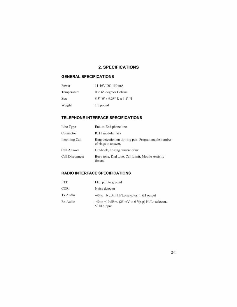
GENERAL SPECIFICATIONS
Power 11-16V DC 150 mA
Temperature 0 to 65 degrees Celsius
Size 5.5″ W x 6.25″ D x 1.4″ H
Weight 1.0 pound
TELEPHONE INTERFACE SPECIFICATIONS
Line Type End-to-End phone line
Connector RJ11 modular jack
Incoming Call Ring detection on tip-ring pair. Programmable numberof rings to answer.
Call Answer Off-hook, tip ring current draw
Call Disconnect Busy tone, Dial tone, Call Limit, Mobile Activitytimers
RADIO INTERFACE SPECIFICATIONS
PTT FET pull to ground
COR Noise detector
Tx Audio -40 to +6 dBm. Hi/Lo selector. 1 kΩ output
Rx Audio -40 to +10 dBm. (25 mV to 6 Vp-p) Hi/Lo selector.50 kΩ input.
Section 2. Specifications
2-2
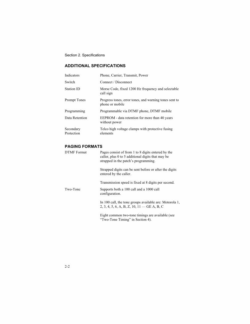
ADDITIONAL SPECIFICATIONS
Indicators Phone, Carrier, Transmit, Power
Switch Connect / Disconnect
Station ID Morse Code, fixed 1200 Hz frequency and selectablecall sign
Prompt Tones Progress tones, error tones, and warning tones sent tophone or mobile
Programming Programmable via DTMF phone, DTMF mobile
Data Retention EEPROM - data retention for more than 40 yearswithout power
SecondaryProtection
Telco high voltage clamps with protective fusingelements
PAGING FORMATSDTMF Format Pages consist of from 1 to 8 digits entered by the
caller, plus 0 to 5 additional digits that may bestrapped in the patch’s programming.
Strapped digits can be sent before or after the digitsentered by the caller.
Transmission speed is fixed at 8 digits per second.
Two-Tone Supports both a 100 call and a 1000 callconfiguration.
In 100 call, the tone groups available are: Motorola 1,2, 3, 4, 5, 6, A, B, Z, 10, 11 — GE A, B, C
Eight common two-tone timings are available (see“Two-Tone Timing” in Section 4).
3-1
3. OPERATION
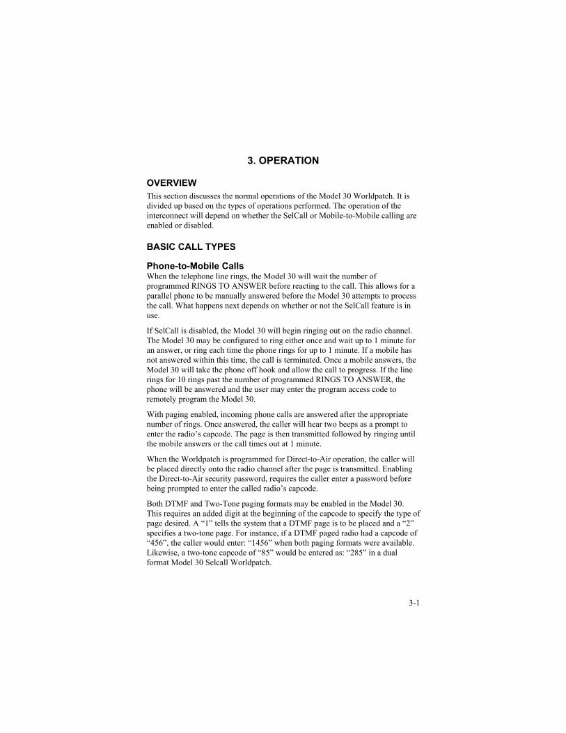
OVERVIEWThis section discusses the normal operations of the Model 30 Worldpatch. It isdivided up based on the types of operations performed. The operation of theinterconnect will depend on whether the SelCall or Mobile-to-Mobile calling areenabled or disabled.
BASIC CALL TYPES
Phone-to-Mobile CallsWhen the telephone line rings, the Model 30 will wait the number ofprogrammed RINGS TO ANSWER before reacting to the call. This allows for aparallel phone to be manually answered before the Model 30 attempts to processthe call. What happens next depends on whether or not the SelCall feature is inuse.
If SelCall is disabled, the Model 30 will begin ringing out on the radio channel.The Model 30 may be configured to ring either once and wait up to 1 minute foran answer, or ring each time the phone rings for up to 1 minute. If a mobile hasnot answered within this time, the call is terminated. Once a mobile answers, theModel 30 will take the phone off hook and allow the call to progress. If the linerings for 10 rings past the number of programmed RINGS TO ANSWER, thephone will be answered and the user may enter the program access code toremotely program the Model 30.
With paging enabled, incoming phone calls are answered after the appropriatenumber of rings. Once answered, the caller will hear two beeps as a prompt toenter the radio’s capcode. The page is then transmitted followed by ringing untilthe mobile answers or the call times out at 1 minute.
When the Worldpatch is programmed for Direct-to-Air operation, the caller willbe placed directly onto the radio channel after the page is transmitted. Enablingthe Direct-to-Air security password, requires the caller enter a password beforebeing prompted to enter the called radio’s capcode.
Both DTMF and Two-Tone paging formats may be enabled in the Model 30.This requires an added digit at the beginning of the capcode to specify the type ofpage desired. A “1” tells the system that a DTMF page is to be placed and a “2”specifies a two-tone page. For instance, if a DTMF paged radio had a capcode of“456”, the caller would enter: “1456” when both paging formats were available.Likewise, a two-tone capcode of “85” would be entered as: “285” in a dualformat Model 30 Selcall Worldpatch.
Section 3. Operation
3-2
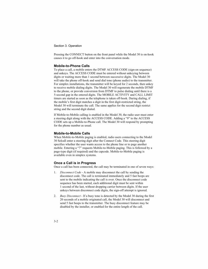
Pressing the CONNECT button on the front panel while the Model 30 is on-hookcauses it to go off-hook and enter into the conversation mode.
Mobile-to-Phone CallsTo place a call, a mobile enters the DTMF ACCESS CODE (sign-on sequence)and unkeys. The ACCESS CODE must be entered without unkeying betweendigits or waiting more than 1 second between successive digits. The Model 30will take the phone off-hook and send dial tone (phone audio) to the transmitter.For simplex installations, the transmitter will be keyed for 2 seconds, then unkeyto receive mobile dialing digits. The Model 30 will regenerate the mobile DTMFto the phone, or provide conversion from DTMF to pulse dialing until there is a5-second gap in the entered digits. The MOBILE ACTIVITY and CALL LIMITtimers are started as soon as the telephone is taken off-hook. During dialing, ifthe mobile’s first digit matches a digit in the first digit-restricted string, theModel 30 will terminate the call. The same applies for the second digit restrictstring and the second digit dialed.
If Mobile-to-Mobile calling is enabled in the Model 30, the radio user must entera steering digit along with the ACCESS CODE. Adding a “9” to the ACCESSCODE sets up a Mobile-to-Phone call. The Model 30 will respond by promptingfor the phone number as usual.
Mobile-to-Mobile CallsWhen Mobile-to-Mobile paging is enabled, radio users connecting to the Model30 Selcall enter a steering digit after the Connect Code. This steering digitspecifies whether the user wants access to the phone line or to page anothermobile. Entering a “7” requests Mobile-to-Mobile paging. This is followed by apage-type digit (if required) and the capcode. Mobile-to-Mobile paging isavailable even in simplex systems.
Once a Call is in ProgressOnce a call has been connected, the call may be terminated in one of seven ways:
1. Disconnect Code - A mobile may disconnect the call by sending thedisconnect code. The call is terminated immediately and 5 fast beeps aresent to the mobile indicating the call is over. Once the disconnect codesequence has been started, each additional digit must be sent within1 second of the last, without dropping carrier between digits. If the userunkeys between disconnect code digits, the sign-off attempt is ignored.
2. Busy Disconnect - If a busy tone is detected by the Model 30 during the first20 seconds of a mobile originated call, the Model 30 will disconnect andsend 5 fast beeps to the transmitter. The busy disconnect feature may bedisabled by the installer, or enabled for the entire length of the call.
Section 3. Operation
3-3
3. Dial Tone Disconnect - If continuous dial tone is detected after theconversation mode of a call has begun, the call will be terminated and 5 fastbeeps sent to the mobile. This feature may be disabled by the installer.
4. Mobile Activity - The mobile must transmit at least once during the mobileactivity interval. If not, the call will be terminated and the 5 fast beeps willbe sent to the mobile. During the conversation, a single beep will be sent tothe phone and the mobile every 3 seconds starting at 12 seconds before themobile activity timer expires. This beep serves as a warning to both thetelephone user and the mobile user.
5. Call Limit - Each call is limited in length. Once the call limit timer hasexpired, the call is terminated and 5 fast beeps are sent to the mobile.Double warning beeps are sent to the telephone and mobile every 3 secondsstarting 15 seconds before the call limit timer expires. If programmed to doso, the Model 30 may allow the mobile to extend the call limit time bypressing the “*” key.
6. Phone Party Disconnect - The phone party may disconnect the call byentering a DTMF “#0”. The call will then disconnect in the same manner asif the mobile had initiated the disconnect.
7. Connect Button - Pressing the connect button while the Model 30 is off-hook terminates the call in progress and forces the Model 30 back into theon-hook idle mode.
Remote Programming AccessThe mobile user may enter the program access code to gain access to remoteprogramming.
MODEL 30 FEATURES
DTMF or Pulse Dial RegenerationThe Model 30 defaults to regenerating the DTMF digits received from the mobileuser to dial the telephone. This allows the unit to present a pre-set level andquality of DTMF to the phone line regardless of conditions on the channel. Thisfunction can also be programmed to translate the mobile’s DTMF into pulsedialing, should that be required by the connected telephone service.
While dial regeneration is active, audio from the mobile unit connected to thesystem is not passed to the telephone line.
Dialed number regeneration is a timed function. By default, the mobile user has 3seconds to dial each digit of the phone number. This time may be programmed tobe from 0 to 60 seconds. Regeneration time must end before conversation cantake place. This can either be done by waiting until the regeneration timer lapses
Section 3. Operation
3-4
or by forcing it to end by sending a DTMF “*” as the last digit dialed. (The “*” isnot regenerated.)
Toll RestrictionThe Model 30 will not allow a mobile to dial a telephone number whose first orsecond digit is in either toll restrict table. These tables can both contain up to fourdigits. Toll restriction may be turned off by programming both tables as blank.
A toll defeat code is provided to allow “privileged” users to avoid the tollrestriction when making calls. This code is used in place of the access code togain access to the phone line.
Call Limit TimerThe call timer determines the maximum time that a call may last before beingterminated. The call limit timer may be reset using a DTMF “*” if programmedto do so. Double warning beeps are sent to the telco and mobile every 3 seconds,starting 15 seconds before the call is terminated.
Mobile Activity TimeThe mobile activity sets the amount of time that may elapse without the Model30 detecting a mobile transmission. When this timer expires, the call isterminated. This timer assures that if a mobile travels out of range (loses controlof the interconnect), the conversation will be terminated even though the mobilecannot manually terminate the call. Single warning beeps are sent to the telco andmobile every 3 seconds, starting 12 seconds before the call is terminated.
Courtesy ToneA courtesy tone is a short 50 millisecond beep that prompts the phone party tobegin speaking. This is especially useful when phone callers are not aware thatthey must wait for the mobile to unkey before speaking.
Repeat EnableThe Model 30 includes the capability to turn a duplex station into a carriercontrolled repeater. When enabled, the Model 30 will repeat audio any time itreceives carrier detection. After receive carrier drops, the transmitter is held upfor the programmable REPEATER TRANSMIT HOLD TIME.
Interconnect “Security”Interconnect Security is intended to discourage casual eavesdropping. During aphone call with the security disabled, the mobile audio is routed to the transmitter(repeated). With security mode enabled, an annoying tone is sent to thetransmitter while the mobile speaks. This masks the mobile’s half of theconversation to other listening mobiles or scanners.
Section 3. Operation
3-5
Direct to AirThe user may program the unit to place the received call Direct to Air. If thisfunction is enabled, it places the caller on the air without waiting to get aresponse from the mobile user to complete the call. This type of operation isparticularly useful for in-house systems where the Model 30 is on an extension ofa PBX.
AutodialThe Model 30 allows up to 50 autodials to be stored for speed dialing. To accessthe autodials, the user enters his/her connect code and, within 1 second, theautodial number. For example, if the connect code is “*” and the mobile wishesto autodial the phone number stored at location 5, the user enters “*5”, and thenumber is dialed. Up to 16 digits may be programmed into each autodial slot.Mobile users can be restricted to only accessing the phone by using the Autodialnumbers. If a mobile user initiates a call while this feature is enabled, that usercan only request a valid Autodial number. If the user tries to dial a regular phonenumber or to access an Autodial slot that is empty (not programmed), the call isbe terminated and the Model 30 issues an error tone (warble) on the channelbefore unkeying the transmitter.
Hook-FlashThe hook flash, when enabled, allows the mobile to flash the telephone line. Forexample, if you are on a PBX system, the PBX may require a hook flash toperform certain functions. To flash the line, the user sends a “*0” during a call.
Non-DTMF Access to Phone LineWhen enabled, non-DTMF equipped mobiles can gain access to the phone lineby simply keying up four times in rapid succession. If four carrier signals arereceived less than 1 second apart, the phone line will be taken off hook andautodial #1 will be dialed. The phone side can disconnect the call by sending“#0”.
Auxiliary Output ControlThe Auxiliary Output allows an external device at the radio site to be controlledwith DTMF over the radio channel or from the phone. This is useful, forexample, to control an antenna switch for coverage of multiple areas. TheAuxiliary Output is controlled by entering different codes to turn on or off theoutput. This can be accessed from either the radio or the phone. The factorydefaults for these codes are 567 to turn “on” the output and 890 to turn “off” theoutput. These may be programmed by the user to be any code of up to nine digitseach. When the On code is decoded by the Model 30, the FET on the AuxiliaryOutput will be switched on which pulls the open drain line to ground. The FET iscapable of sinking a maximum of 200 mA DC. The output stays in the assigned
Section 3. Operation
3-6
state until commanded to switch states. The output state is saved in the unit’snon-volatile memory and is restored as set even if power is cycled.
Call AlertWhen enabled, Call Alert allows the Model 30 to key up during an existingMobile-to-Mobile conversation and send two quick beeps over the air when atelephone call comes in. The mobiles may then elect to stop their conversation soone of them may answer the call.
Dual Function Connect ButtonThis is designed for installations where the Model 30 is used on an operator’sdesk to route calls between the office and the field. In normal operation when theConnect button is pressed while the system is idle, the phone line is placeddirectly on the air in conversation mode. Enabling this option instructs the Model30 to ring out over the air to hail the mobile user when the button is pressed. Ifthe channel has activity, the phone line will be placed in conversation modewhen the button is pressed.
SIMPLEX OPERATION
Simplex ModesThere are six simplex modes.
Simplex VOXThis is the standard simplex mode that keys the transmitter using phone voice(VOX) detection. When neither party is talking, the Model 30 watches for eitherVOX or carrier detection. When the Model 30 detects VOX, it keys thetransmitter and allows the telephone audio to pass to the transmitter. When VOXdrops and the VOX HOLD timer expires, the transmitter is dropped and theModel 30 returns to waiting. When the Model 30 detects carrier, it allows mobileaudio to pass to the telephone. When carrier drops, and the COR HOLD timerexpires, the Model 30 returns to waiting.
The digital voice delay option board may be installed to enhance the simplexVOX mode. Since the Model 30 uses the voice detector to know when to key thetransmitter, the first syllable can be lost while the transmitter comes up. CTCSSdecoders can also contribute to the lost syllables. Adding the digital voice delayboard delays the phone audio so that the transmitter will have plenty of time toget “on line” before the phone audio is passed to the mobile.
Simplex VOX with PrekeyThis mode is identical to the above mode, with one exception. When carrierdrops, it is assumed that the telephone will want to start talking, so the Model 30“prekeys” the transmitter. This reduces the chance of lost syllables while thetransmitter is coming up to full power. If the phone party does not begin speaking
Section 3. Operation
3-7
before the VOX HOLD TIME expires (typically one second), the transmitterunkeys. The Model 30 then begins watching for either VOX or mobile activity.
Simplex SamplingWhen the Model 30 is connected to a radio that switches very fast betweentransmit and receive (and is not working through a repeater) the Sampling modemay be used. There are two parameters that affect sampling modes, they are theSAMPLE RATE and the SAMPLE WIDTH times. This mode begins with thetransmitter keyed up and audio passing from the telco to the mobile. When theSAMPLE RATE timer expires, the transmitter is unkeyed and the SAMPLEWIDTH timer is started. When the SAMPLE WIDTH timer expires, the Model30 looks for carrier detection. If carrier is not present, the transmitter is re-keyedand the cycle starts again. If carrier is present, telco to mobile audio is shut downand mobile to telco audio is opened. Audio is passed from the mobile to the telcountil COR drops and the COR HOLD timer expires; the cycle starts again.
Sampling with VOX to Extend Sample IntervalThis mode is identical to SIMPLEX SAMPLING, but the Model 30 looks forVOX indication also. When VOX is up, the SAMPLE RATE is extended to 4times the normal sampling time. When the Model 30 detects VOX, the telephoneis speaking, and therefore sampling only needs to happen 1/4 as often.
Intelligent Simplex ModeWhen the Model 30 is not working through a repeater (not connected to a controlstation), the Intelligent Simplex mode will provide the best possible operation.This mode uses VOX, the SAMPLE WIDTH timer and audio delay to providepremium simplex operation. As long as VOX is detected, the transmitter is keyedand audio is passed from the telco to the mobile. When VOX drops for theSAMPLE WIDTH time (or more), the Model 30 allows the rest of the audio (stilltrapped in the delay) to go out the transmitter. Once the audio is out thetransmitter and silence (the gap) is being transmitted, the transmitter is unkeyed.Just before the end of the gap reaches the transmitter, carrier is checked. If carrieris present, the mobile takes over the call. If carrier is not present, the transmitteris again keyed, and the remaining audio in the delay is allowed out thetransmitter. Using the delay and timing the gap, the Model 30 is capable ofsampling between words without the loss of telephone audio. THIS MODE ISONLY AVAILABLE WHEN THE OPTIONAL DIGITAL VOICE DELAYHAS BEEN INSTALLED.
Simplex Phone Key ControlVOX operation may now be bypassed and transmit & receive can be controlledby the phone caller using the “*” and “#” keys on a DTMF phone set. Pressingthe “*” momentarily will key the transmitter and the caller may talk. Pressing the“#” momentarily will unkey it. This allows trained callers to have very positivecontrol in simplex dispatch operations.
Section 3. Operation
3-8
Simplex TimersVOX Hold TimeSets the VOX hold time, or the time that the VOX detection must be gone beforethe telco side of the conversation is assumed over. This time should be set to theminimum required as it slows down the conversation, but a time too short willcause the conversation to flip to the mobile side prematurely. This timer onlyaffects the VOX simplex modes.
COR Hold TimeA hold time may be added to the receive carrier detector in simplex mode toreduce the effects of “picket fencing.” When mobiles operate in fringe areas, orthrough multi-path zones, the carrier may momentarily drop. When it does, thepatch will assume that the mobile unkeyed, and could key the transmitter toallow the phone party to begin speaking. The COR hold time will allow thereceive audio to be muted to the phone party, but won’t assume the mobile hasunkeyed until the COR hold time expires.
Sample RateSets the rate that the Model 30 will sample for carrier. This is NOT the amount oftime that it looks for carrier, but how often it looks. The sample rate timer is usedfor simplex sampling, and simplex sampling w/VOX extend. Note that simplexIntelligent mode does not use this timer.
Auto Sample SetupThis command allows the simplex sample window duration to be setautomatically for any radio. Once the command is executed, the Model 30 willkey the radio for 2 seconds allowing time to generate a DTMF digit into thereceiver using a DTMF equipped radio. The Model 30 will unkey the transmitterand time how long it takes to decode the DTMF. This is saved as the samplewidth time. Commands are available to increment and decrement the samplewindow in 10-millisecond increments for fine tuning.
OPTIONSA Digital Voice Option is available for premium simplex operation.
4-1
4. PROGRAMMING
PROGRAM MODE ACCESSThe Model 30 may be programmed from any DTMF equipped radio that canaccess the unit, or by using DTMF over the telephone line.
When programming over the radio, simply enter the program mode access code.The Model 30 will respond with a five-beep “go-ahead chirp” to indicate properaccess. The transmitter will key after each command is entered to indicate asuccessful programming step or an error condition.
Accessing programming mode through the telephone operates differently basedon how paging is enabled in the system. If paging is not enabled, the unitbehaves the same as a non-Selcall Model 30 would. This means the unit willringout over the air, until the Ringout time expires. The phone is then answeredby the Model 30 giving the caller the opportunity to enter the Program AccessCode (default 12030).
When either paging format is enabled as a single format within the system, theProgram Access Code may be entered instead of a cap code. If both pagingformats are enabled, the Program Access Code must be preceded by either of thepage type digits (a 1 or 2). If the number of digits that the caller is required toenter for a cap code is five or less, the Program Access code is entered as is. Ifthe number of digits a caller is required to enter is greater than 5, the ProgramAccess Code is entered, but must be followed by enough additional digits tosatisfy the number of digits expected. This is because the Worldpatch does notbegin to analyze the input string until it has seen the required number of digits.
To program the Model 30, the 5-digit user programmable “program mode accesscode” must be entered. The access code is 12030 as shipped from the factory, butmay be changed to any 5-digit code. Please note that the default program modeaccess code used here is different than the one used in non-SelCall units.
The program mode may also be accessed from the telephone by dialing theprogram mode access code during a call.
ENTERING A PROGRAM COMMANDTo execute a program command, a DTMF number is entered followed by the “#”key. Once the “#” has been entered, the Model 30 will respond with the 5-beep“go-ahead chirp” indicating that the command was accepted or a high-low “errortone” sequence indicating that an invalid command was received. Somecommands require additional numbers, as in the case of the connect code. Forthese commands, the Model 30 will send two fast beeps indicating that additionaldigits are required. Commands should be entered one at a time (do not try to“string” commands together) until the go-ahead or error tones are sent. While
Section 4. Programming
4-2
programming, a key must be depressed every 60 second, or the Model 30 willautomatically exit the program mode, returning to normal operation.
The Model 30 offers no method of viewing the programmed settings (there is noRS-232 port for CRT or printer.) As such, it is important to be careful duringprogramming and to keep track of all programmed settings. If the Model 30 is inan unknown programming state, the settings may be reset to the factory defaultsfrom the front panel or by using a DTMF command. Care should be exercisedwhen resetting the unit if existing Model 30 users are expecting certain accessand disconnect codes.
To force the Model 30 to reset its programming to default values, from the frontpanel, complete the following steps:
1. Turn off power to the Model 30.2. Press and hold the Connect button.3. While holding the button in, turn on the power to the Model 30.4. Hold the Connect button until the phone light starts blinking (about 4
seconds), then release the button.
The Model 30 should now be reset to default values.
PROGRAMMING COMMANDSA number of new programming commands have been added to allow the pagingto be tailored to the systems needs. In order to fit these commands into the Model30, several changes were made to existing commands. These changes consolidateand regroup several of the existing commands into a more logical structure. Morecommands now use a “Command-#, Data-#” format. Programmers should findthese commands easy to use.
The data portion of these commands may be from one to several digits in length.The length is determined by the range of allowable values or the maximum stringlength in the case of passwords. With the exception of the program access code(this must always be 5 digits), the data entered only needs to be as many digits asnecessary. For instance, if the allowable range for a value is 1 to 999 and the datato be programmed is 6, the programmer may enter: 6, 06 or 006. In the followinglist of commands, the default setting for each command is shown in the far right-hand column.
Access and Disconnect CodesIn order to initiate and terminate phone calls, a mobile user must send a DTMFaccess code. In all three cases the “#” character is used to terminate both thecommand and the data string that follows it. In the case of the Disconnect code,the “*” is used to specify a “#”. The “#” character terminates the command.
01# ______# Connect Code 1 - 9 digits (0 to 9, and *) *1
Section 4. Programming
4-3
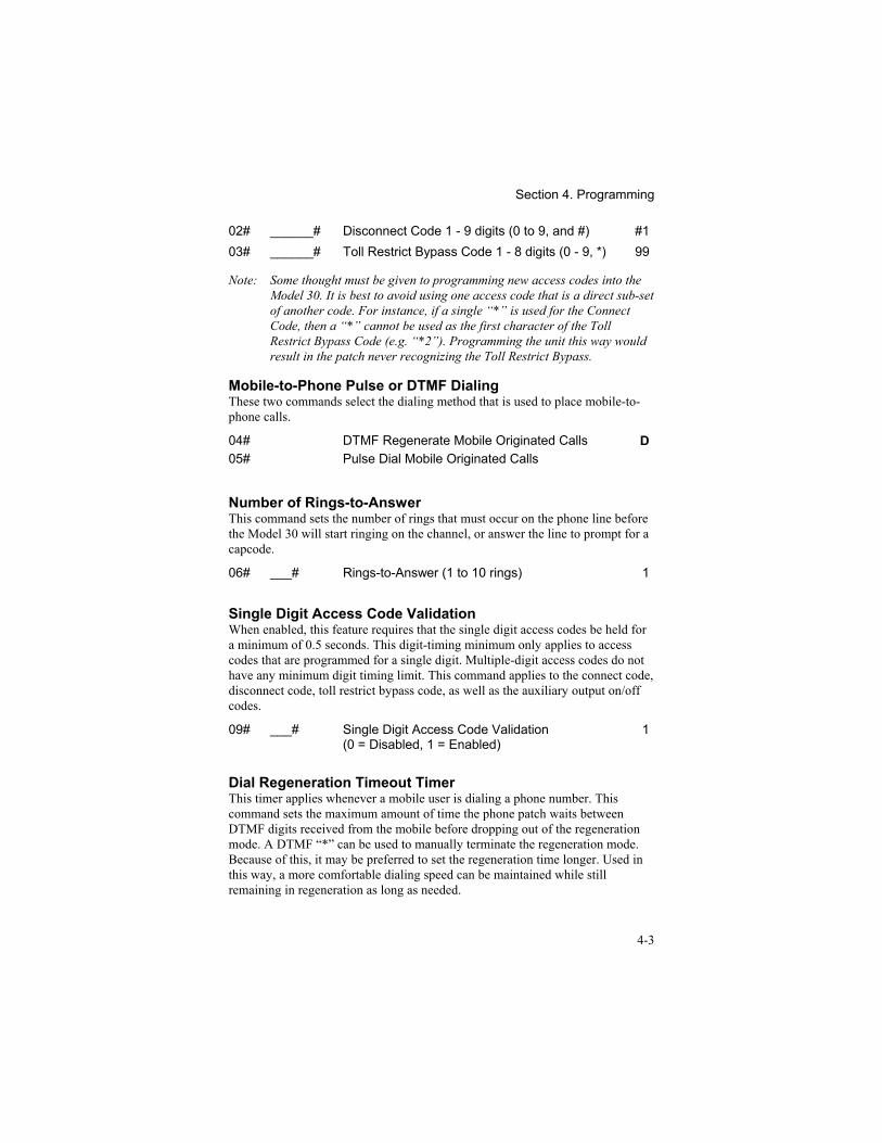
02# ______# Disconnect Code 1 - 9 digits (0 to 9, and #) #103# ______# Toll Restrict Bypass Code 1 - 8 digits (0 - 9, *) 99
Note: Some thought must be given to programming new access codes into theModel 30. It is best to avoid using one access code that is a direct sub-setof another code. For instance, if a single “*” is used for the ConnectCode, then a “*” cannot be used as the first character of the TollRestrict Bypass Code (e.g. “*2”). Programming the unit this way wouldresult in the patch never recognizing the Toll Restrict Bypass.
Mobile-to-Phone Pulse or DTMF DialingThese two commands select the dialing method that is used to place mobile-to-phone calls.
04# DTMF Regenerate Mobile Originated Calls D05# Pulse Dial Mobile Originated Calls
Number of Rings-to-AnswerThis command sets the number of rings that must occur on the phone line beforethe Model 30 will start ringing on the channel, or answer the line to prompt for acapcode.
06# ___# Rings-to-Answer (1 to 10 rings) 1
Single Digit Access Code ValidationWhen enabled, this feature requires that the single digit access codes be held fora minimum of 0.5 seconds. This digit-timing minimum only applies to accesscodes that are programmed for a single digit. Multiple-digit access codes do nothave any minimum digit timing limit. This command applies to the connect code,disconnect code, toll restrict bypass code, as well as the auxiliary output on/offcodes.
09# ___# Single Digit Access Code Validation(0 = Disabled, 1 = Enabled)
1
Dial Regeneration Timeout TimerThis timer applies whenever a mobile user is dialing a phone number. Thiscommand sets the maximum amount of time the phone patch waits betweenDTMF digits received from the mobile before dropping out of the regenerationmode. A DTMF “*” can be used to manually terminate the regeneration mode.Because of this, it may be preferred to set the regeneration time longer. Used inthis way, a more comfortable dialing speed can be maintained while stillremaining in regeneration as long as needed.
Section 4. Programming
4-4
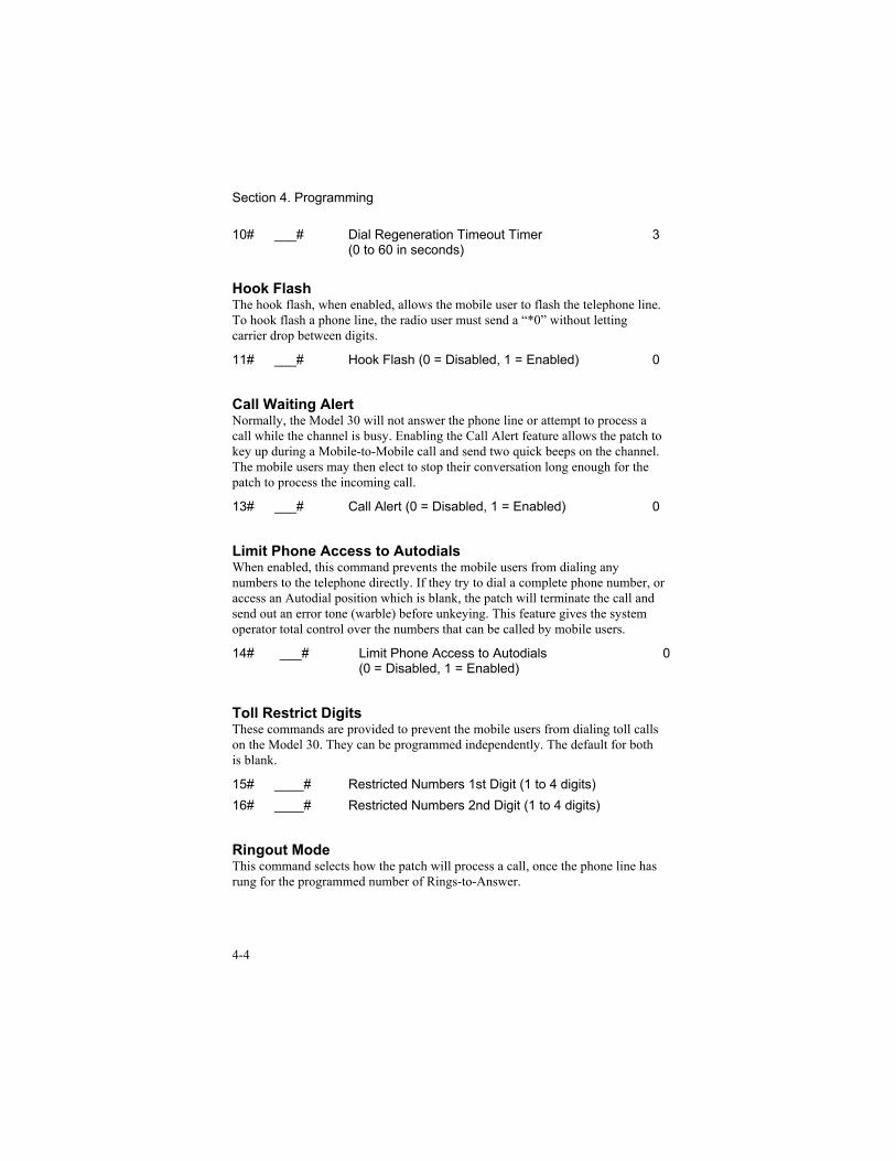
10# ___# Dial Regeneration Timeout Timer(0 to 60 in seconds)
3
Hook FlashThe hook flash, when enabled, allows the mobile user to flash the telephone line.To hook flash a phone line, the radio user must send a “*0” without lettingcarrier drop between digits.
11# ___# Hook Flash (0 = Disabled, 1 = Enabled) 0
Call Waiting AlertNormally, the Model 30 will not answer the phone line or attempt to process acall while the channel is busy. Enabling the Call Alert feature allows the patch tokey up during a Mobile-to-Mobile call and send two quick beeps on the channel.The mobile users may then elect to stop their conversation long enough for thepatch to process the incoming call.
13# ___# Call Alert (0 = Disabled, 1 = Enabled) 0
Limit Phone Access to AutodialsWhen enabled, this command prevents the mobile users from dialing anynumbers to the telephone directly. If they try to dial a complete phone number, oraccess an Autodial position which is blank, the patch will terminate the call andsend out an error tone (warble) before unkeying. This feature gives the systemoperator total control over the numbers that can be called by mobile users.
14# ___# Limit Phone Access to Autodials(0 = Disabled, 1 = Enabled)
0
Toll Restrict DigitsThese commands are provided to prevent the mobile users from dialing toll callson the Model 30. They can be programmed independently. The default for bothis blank.
15# ____# Restricted Numbers 1st Digit (1 to 4 digits)16# ____# Restricted Numbers 2nd Digit (1 to 4 digits)
Ringout ModeThis command selects how the patch will process a call, once the phone line hasrung for the programmed number of Rings-to-Answer.
Section 4. Programming
4-5
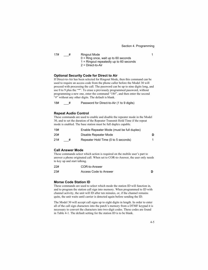
17# ___# Ringout Mode0 = Ring once, wait up to 60 seconds1 = Ringout repeatedly up to 60 seconds2 = Direct-to-Air
1
Optional Security Code for Direct to AirIf Direct-to-Air has been selected for Ringout Mode, then this command can beused to require an access code from the phone caller before the Model 30 willproceed with processing the call. The password can be up to nine digits long, anduse 0 to 9 plus the “*”. To erase a previously programmed password, withoutprogramming a new one, enter the command “18#”, and then enter the second“#” without any other digits. The default is blank.
18# ___# Password for Direct-to-Air (1 to 9 digits)
Repeat Audio ControlThese commands are used to enable and disable the repeater mode in the Model30, and to set the duration of the Repeater Transmit Hold Time if the repeatmode is enabled. The base station must be full duplex capable.
19# Enable Repeater Mode (must be full duplex)20# Disable Repeater Mode D21# ___# Repeater Hold Time (0 to 5 seconds) 1
Call Answer ModeThese commands select which action is required on the mobile user’s part toanswer a phone originated call. When set to COR-to-Answer, the user only needsto key up and start talking.
22# COR-to-Answer23# Access Code to Answer D
Morse Code Station IDThese commands are used to select which mode the station ID will function in,and to program the station call sign into memory. When programmed to ID withchannel activity, the unit will ID after ten minutes, or, if the channel remainsquite, the unit waits until carrier is detected again before sending the ID.
The Model 30 will accept call signs up to eight digits in length. In order to enterall of the call sign characters into the patch’s memory from a DTMF keypad it isnecessary to convert the characters into two-digit codes. These codes are foundin Table 4-1. The default setting for the station ID is to be blank.
Section 4. Programming
4-6
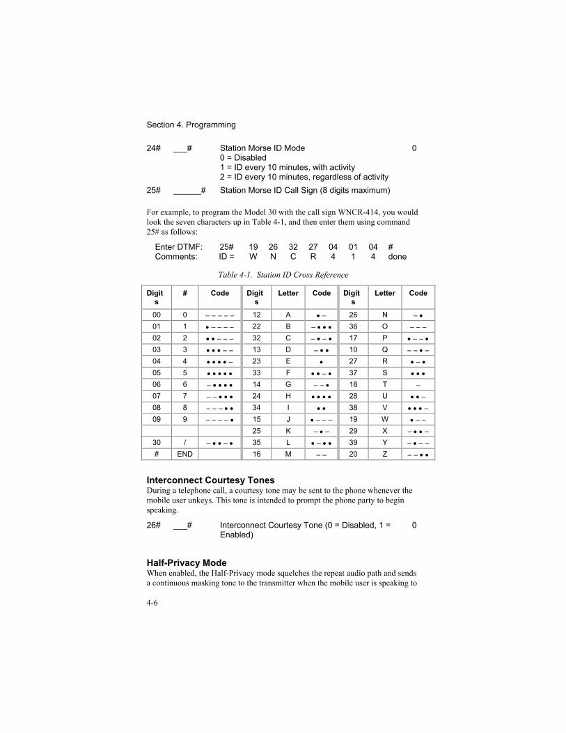
24# ___# Station Morse ID Mode0 = Disabled1 = ID every 10 minutes, with activity2 = ID every 10 minutes, regardless of activity
0
25# ______# Station Morse ID Call Sign (8 digits maximum)
For example, to program the Model 30 with the call sign WNCR-414, you wouldlook the seven characters up in Table 4-1, and then enter them using command25# as follows:
Enter DTMF: 25# 19 26 32 27 04 01 04 #Comments: ID = W N C R 4 1 4 done
Table 4-1. Station ID Cross Reference
Digits
# Code Digits
Letter Code Digits
Letter Code
00 0 − − − − − 12 A • − 26 N − •01 1 • − − − − 22 B − • • • 36 O − − −02 2 • • − − − 32 C − • − • 17 P • − − •03 3 • • • − − 13 D − • • 10 Q − − • −04 4 • • • • − 23 E • 27 R • − •05 5 • • • • • 33 F • • − • 37 S • • •06 6 − • • • • 14 G − − • 18 T −07 7 − − • • • 24 H • • • • 28 U • • −08 8 − − − • • 34 I • • 38 V • • • −09 9 − − − − • 15 J • − − − 19 W • − −
25 K − • − 29 X − • • −30 / − • • − • 35 L • − • • 39 Y − • − −# END 16 M − − 20 Z − − • •
Interconnect Courtesy TonesDuring a telephone call, a courtesy tone may be sent to the phone whenever themobile user unkeys. This tone is intended to prompt the phone party to beginspeaking.
26# ___# Interconnect Courtesy Tone (0 = Disabled, 1 =Enabled)
0
Half-Privacy ModeWhen enabled, the Half-Privacy mode squelches the repeat audio path and sendsa continuous masking tone to the transmitter when the mobile user is speaking to
Section 4. Programming
4-7
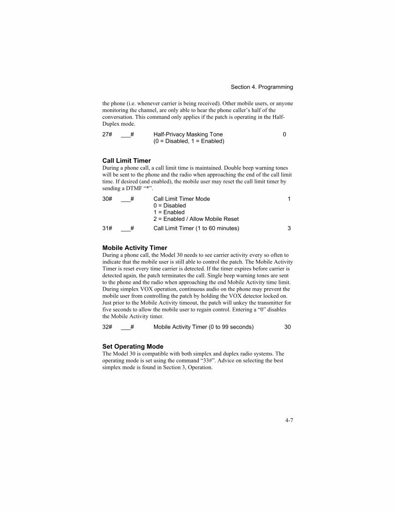
the phone (i.e. whenever carrier is being received). Other mobile users, or anyonemonitoring the channel, are only able to hear the phone caller’s half of theconversation. This command only applies if the patch is operating in the Half-Duplex mode.
27# ___# Half-Privacy Masking Tone(0 = Disabled, 1 = Enabled)
0
Call Limit TimerDuring a phone call, a call limit time is maintained. Double beep warning toneswill be sent to the phone and the radio when approaching the end of the call limittime. If desired (and enabled), the mobile user may reset the call limit timer bysending a DTMF “*”.
30# ___# Call Limit Timer Mode0 = Disabled1 = Enabled2 = Enabled / Allow Mobile Reset
1
31# ___# Call Limit Timer (1 to 60 minutes) 3
Mobile Activity TimerDuring a phone call, the Model 30 needs to see carrier activity every so often toindicate that the mobile user is still able to control the patch. The Mobile ActivityTimer is reset every time carrier is detected. If the timer expires before carrier isdetected again, the patch terminates the call. Single beep warning tones are sentto the phone and the radio when approaching the end Mobile Activity time limit.During simplex VOX operation, continuous audio on the phone may prevent themobile user from controlling the patch by holding the VOX detector locked on.Just prior to the Mobile Activity timeout, the patch will unkey the transmitter forfive seconds to allow the mobile user to regain control. Entering a “0” disablesthe Mobile Activity timer.
32# ___# Mobile Activity Timer (0 to 99 seconds) 30
Set Operating ModeThe Model 30 is compatible with both simplex and duplex radio systems. Theoperating mode is set using the command “33#”. Advice on selecting the bestsimplex mode is found in Section 3, Operation.
Section 4. Programming
4-8
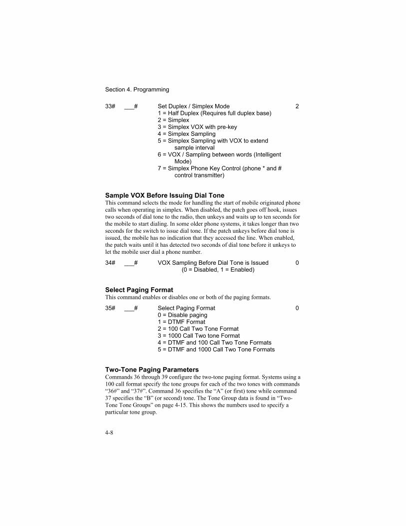
33# ___# Set Duplex / Simplex Mode1 = Half Duplex (Requires full duplex base)2 = Simplex3 = Simplex VOX with pre-key4 = Simplex Sampling5 = Simplex Sampling with VOX to extend
sample interval6 = VOX / Sampling between words (Intelligent
Mode)7 = Simplex Phone Key Control (phone * and #
control transmitter)
2
Sample VOX Before Issuing Dial ToneThis command selects the mode for handling the start of mobile originated phonecalls when operating in simplex. When disabled, the patch goes off hook, issuestwo seconds of dial tone to the radio, then unkeys and waits up to ten seconds forthe mobile to start dialing. In some older phone systems, it takes longer than twoseconds for the switch to issue dial tone. If the patch unkeys before dial tone isissued, the mobile has no indication that they accessed the line. When enabled,the patch waits until it has detected two seconds of dial tone before it unkeys tolet the mobile user dial a phone number.
34# ___# VOX Sampling Before Dial Tone is Issued(0 = Disabled, 1 = Enabled)
0
Select Paging FormatThis command enables or disables one or both of the paging formats.
35# ___# Select Paging Format0 = Disable paging1 = DTMF Format2 = 100 Call Two Tone Format3 = 1000 Call Two tone Format4 = DTMF and 100 Call Two Tone Formats5 = DTMF and 1000 Call Two Tone Formats
0
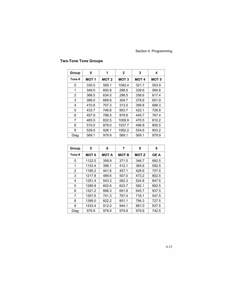
Two-Tone Paging ParametersCommands 36 through 39 configure the two-tone paging format. Systems using a100 call format specify the tone groups for each of the two tones with commands“36#” and “37#”. Command 36 specifies the “A” (or first) tone while command37 specifies the “B” (or second) tone. The Tone Group data is found in “Two-Tone Tone Groups” on page 4-15. This shows the numbers used to specify aparticular tone group.
Section 4. Programming
4-9
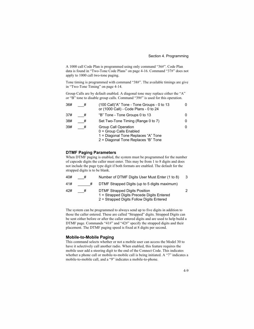
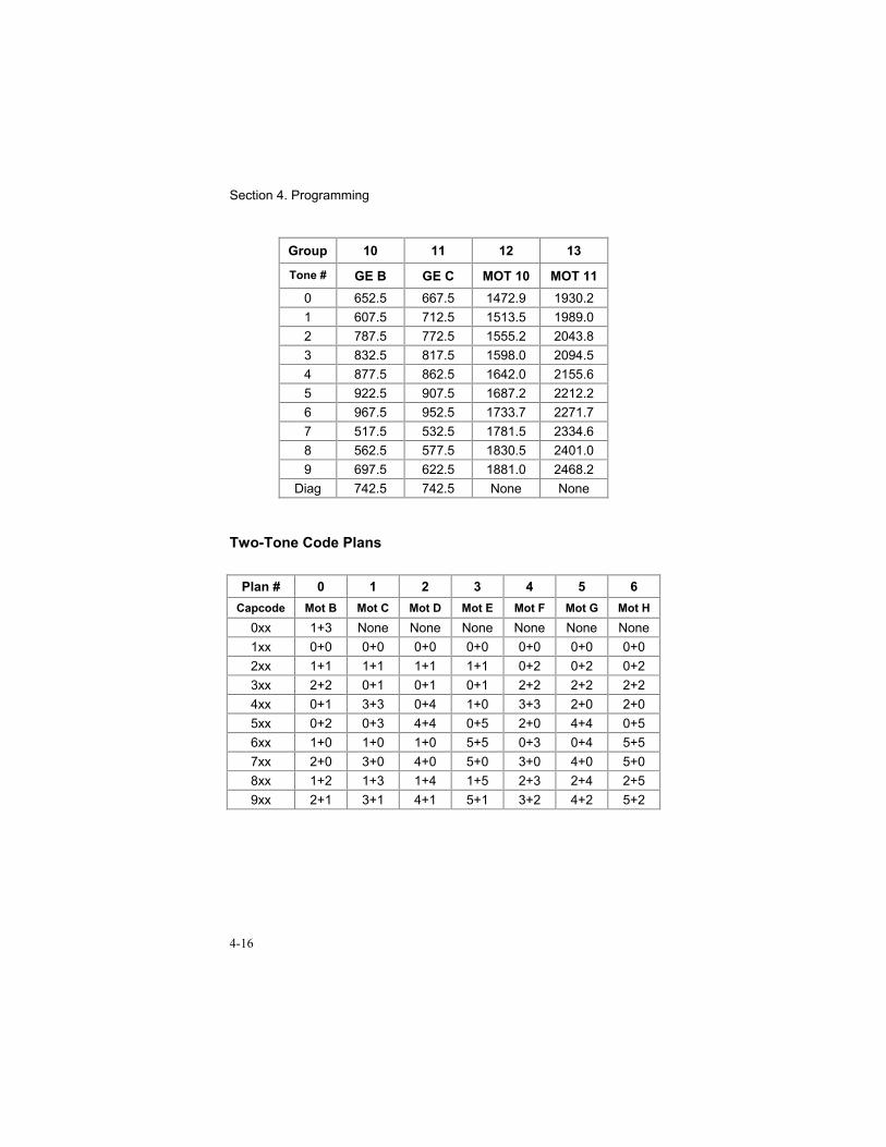
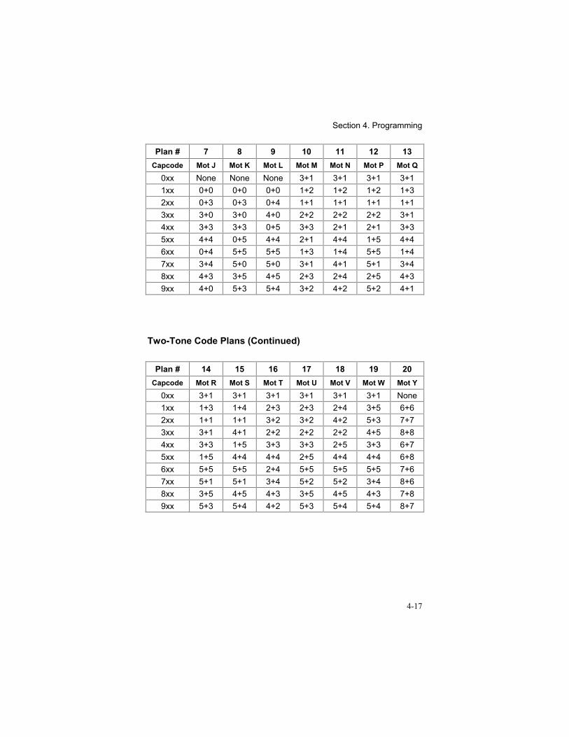
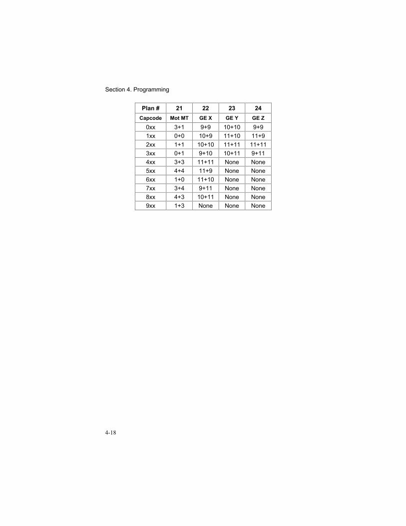
A 1000 call Code Plan is programmed using only command “36#”. Code Plandata is found in “Two-Tone Code Plans” on page 4-16. Command “37#” does notapply to 1000 call two-tone paging.
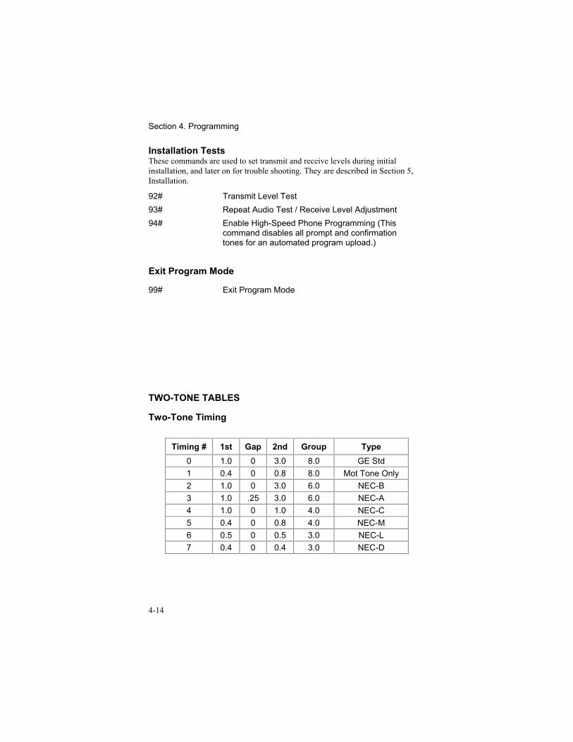
Tone timing is programmed with command “38#”. The available timings are givein “Two-Tone Timing” on page 4-14.
Group Calls are by default enabled. A diagonal tone may replace either the “A”or “B” tone to disable group calls. Command “39#” is used for this operation.
36# ___# (100 Call)“A” Tone - Tone Groups - 0 to 13or (1000 Call) - Code Plans - 0 to 24
0
37# ___# “B” Tone - Tone Groups 0 to 13 038# ___# Set Two-Tone Timing (Range 0 to 7) 039# ___# Group Call Operation
0 = Group Calls Enabled1 = Diagonal Tone Replaces “A” Tone2 = Diagonal Tone Replaces “B” Tone
0
DTMF Paging ParametersWhen DTMF paging is enabled, the system must be programmed for the numberof capcode digits the caller must enter. This may be from 1 to 8 digits and doesnot include the page type digit if both formats are enabled. The default for thestrapped digits is to be blank.
40# ___# Number of DTMF Digits User Must Enter (1 to 8) 3
41# ______# DTMF Strapped Digits (up to 5 digits maximum)
42# ___# DTMF Strapped Digits Position1 = Strapped Digits Precede Digits Entered2 = Strapped Digits Follow Digits Entered
2
The system can be programmed to always send up to five digits in addition tothose the caller entered. These are called “Strapped” digits. Strapped Digits canbe sent either before or after the caller entered digits and are used to help build aDTMF page. Commands “41#” and “42#” specify the strapped digits and theirplacement. The DTMF paging speed is fixed at 8 digits per second.
Mobile-to-Mobile PagingThis command selects whether or not a mobile user can access the Model 30 tohave it selectively call another radio. When enabled, this feature requires themobile user add a steering digit to the end of the Connect Code. This indicateswhether a phone call or mobile-to-mobile call is being initiated. A “7” indicates amobile-to-mobile call, and a “9” indicates a mobile-to-phone.
Section 4. Programming
4-10
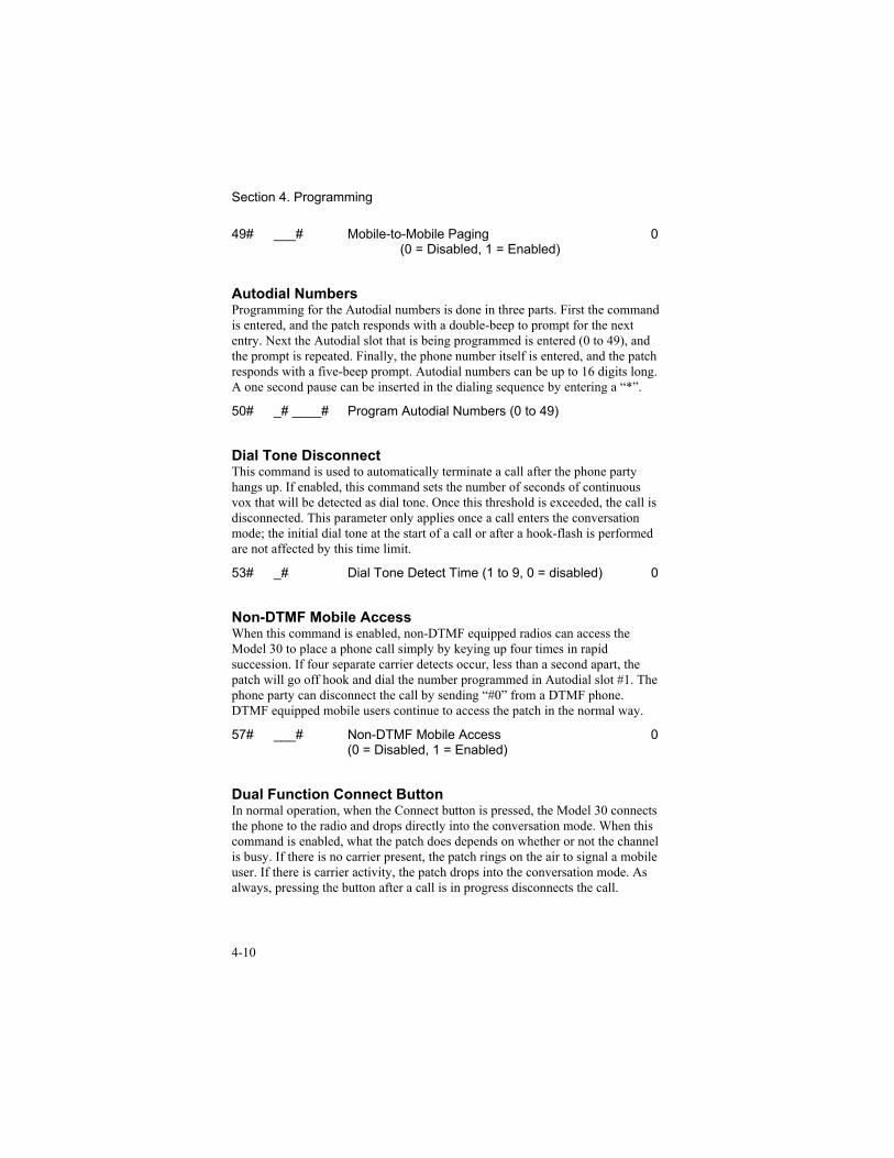
49# ___# Mobile-to-Mobile Paging(0 = Disabled, 1 = Enabled)
0
Autodial NumbersProgramming for the Autodial numbers is done in three parts. First the commandis entered, and the patch responds with a double-beep to prompt for the nextentry. Next the Autodial slot that is being programmed is entered (0 to 49), andthe prompt is repeated. Finally, the phone number itself is entered, and the patchresponds with a five-beep prompt. Autodial numbers can be up to 16 digits long.A one second pause can be inserted in the dialing sequence by entering a “*”.
50# _# ____# Program Autodial Numbers (0 to 49)
Dial Tone DisconnectThis command is used to automatically terminate a call after the phone partyhangs up. If enabled, this command sets the number of seconds of continuousvox that will be detected as dial tone. Once this threshold is exceeded, the call isdisconnected. This parameter only applies once a call enters the conversationmode; the initial dial tone at the start of a call or after a hook-flash is performedare not affected by this time limit.
53# _# Dial Tone Detect Time (1 to 9, 0 = disabled) 0
Non-DTMF Mobile AccessWhen this command is enabled, non-DTMF equipped radios can access theModel 30 to place a phone call simply by keying up four times in rapidsuccession. If four separate carrier detects occur, less than a second apart, thepatch will go off hook and dial the number programmed in Autodial slot #1. Thephone party can disconnect the call by sending “#0” from a DTMF phone.DTMF equipped mobile users continue to access the patch in the normal way.
57# ___# Non-DTMF Mobile Access(0 = Disabled, 1 = Enabled)
0
Dual Function Connect ButtonIn normal operation, when the Connect button is pressed, the Model 30 connectsthe phone to the radio and drops directly into the conversation mode. When thiscommand is enabled, what the patch does depends on whether or not the channelis busy. If there is no carrier present, the patch rings on the air to signal a mobileuser. If there is carrier activity, the patch drops into the conversation mode. Asalways, pressing the button after a call is in progress disconnects the call.
Section 4. Programming
4-11
58# ___# Dual Function Connect Button(0 = Disabled, 1 = Enabled)
0
Multiple Second Dial ToneNormally, when a mobile user initiates a phone call in simplex, the Model 30allows two seconds of dial tone to pass from the phone to the radio, then itunkeys and waits for the user to dial. If no digits are received before the DTMFTimeout timer expires, the patch will disconnect the call. This is adequate exceptin situations where the mobile user must pass through a PBX switch to get anoutside line. The second dial tone would lock up the VOX detector and hold thepatch keyed until the DTMF Timeout timer disconnected the call. When thiscommand is enabled, the Model 30 will pass only two seconds of the second dialtone (stopping the DTMF Timeout timer while it does) and then unkey as it didfor the first dial tone to let the mobile user continue to dial.
59# ___# Multiple Second Dial Tone(0 = Disabled, 1 = Enabled)
0
Repeat Courtesy ToneThis command applies only to repeater operations. When enabled, a courtesytone (a single beep) is added at the end of each mobile user’s transmission toprompt the other mobile to start talking.
69# ___# Repeat Courtesy Tone(0 = Disabled, 1 = Enabled)
0
Simplex Sample RateThis command applies only to simplex operation when Sampling or Samplingwith VOX is enabled. This timer determines how often the patch unkeys to checkthe receive channel for the presence of carrier.
70# ___# Set VOX Sample Rate (0.5 to 1.5 seconds, in100 ms increments, entry range is 5 to 15)
10
VOX Hold TimeThis timer only applies to the Simplex VOX modes. When the VOX detectoroutput goes false, the patch waits for the period set with this command beforeswitching to the receive direction. It should be set as short as practical, in orderto prevent the conversation becoming awkward due to a slow turn around whenthe phone party stops speaking. If it is set too short, the phone party will startdropping out in the middle of sentences. The range is 0.5 to 1.5 seconds, in 100ms increments.
Section 4. Programming
4-12
73# ___# Set VOX Hold Time (entry range is 5 to 15) 10
Automatic Sample Window SetupThese commands are used to configure the Sample Window timer, which controlhow long the patch remains in receive looking for carrier when it samples.Command 78# can only be done from the radio. Once the command is entered,the Model 30 keys up for two seconds. While it is keyed, the technician keys upand sends a continuous DTMF digit. When it unkeys, the Model 30 times howlong it takes after dropping PTT before a valid DTMF digit is decoded. It savesthis time as the Sample Window time. This test should be run only afterinstallation and all level adjustments are complete. Commands 79# and 80#allow the technician to adjust the size of the window manually if operatingexperience indicates the need.
78# ___# Automatic Sample Window Setup79# ___# Increment Sample Window by 10 ms80# ___# Decrement Sample Window by 10 ms
COR Hold TimeThis timer is similar in function to the VOX Hold timer. It sets the amount oftime that carrier detection must go away before the patch reacts to it and switchesfrom receive back to transmit. Valid entries are 0 to 5, in 100 millisecondincrements, giving a range of 0 to 500 milliseconds.
81# ___# Set COR Hold Time ( range is 0 to 5) 0
Busy Tone DetectorThe Model 30 uses its VOX detector to look for the characteristic pattern of busytone during the first 20 seconds of any mobile originated phone call. If it detectsa busy tone it disconnects the call automatically. This is particularly useful onsimplex systems. A disable is provided for this feature because some automatedtelephone voice prompts can be falsely identified as busy tone. This feature canalso be set to be active for the entire call.
85# ___# Set Busy Tone Detect Mode0 = Busy Tone Detection Disabled1 = Disconnect If Busy Detected in First 20
Seconds2 = Disconnect If Busy Detected During Entire
Call
1
Section 4. Programming
4-13
PL Strip OutputThe auxiliary output FET can be configured for use as a PL strip output. Ifenabled, the FET pulls the output to ground during paging, and remains there forthe duration of a page initiated call. This is intended to indicate to the radio thatsubaudible signaling should be turned off.
87# ___# Use Auxiliary Output for PL Strip(0 = Disabled, 1 = Enabled)
0
Auxiliary Output ControlThe Model 30 provides an open drain FET circuit as an auxiliary output. Thiscan be used to control external equipment that is located at the radio site. Whenthe Auxiliary Output is turned ON, the FET pulls the output to ground and holdsit there until the OFF command is received. These commands allow the systemoperator to program new access codes for ON and OFF.
88# ___# Set Auxiliary Output ON Code (1 to 9 digits) 56789# ___# Set Auxiliary Output OFF Code (1 to 9 digits) 890
Program Access CodeThis command allows the system operator to program a new access code in thefield to maintain system security. The Program Mode Access Code must alwaysbe five digits long. The default code is “12030”.
90# ______# Set Program Access Code (Must be 5 digits)
Reset All Parameters to Factory DefaultThis command is used quickly return all programmable parameters in the Model30 to known, factory default values. All programming changes must be re-entered after using this command.
91# Reset All Memory to Factory Defaults
Section 4. Programming
4-14
Installation TestsThese commands are used to set transmit and receive levels during initialinstallation, and later on for trouble shooting. They are described in Section 5,Installation.
92# Transmit Level Test93# Repeat Audio Test / Receive Level Adjustment94# Enable High-Speed Phone Programming (This
command disables all prompt and confirmationtones for an automated program upload.)
Exit Program Mode
99# Exit Program Mode
TWO-TONE TABLES
Two-Tone Timing
Timing # 1st Gap 2nd Group Type0 1.0 0 3.0 8.0 GE Std1 0.4 0 0.8 8.0 Mot Tone Only2 1.0 0 3.0 6.0 NEC-B3 1.0 .25 3.0 6.0 NEC-A4 1.0 0 1.0 4.0 NEC-C5 0.4 0 0.8 4.0 NEC-M6 0.5 0 0.5 3.0 NEC-L7 0.4 0 0.4 3.0 NEC-D
Section 4. Programming
4-15
Two-Tone Tone Groups
Group 0 1 2 3 4
Tone # MOT 1 MOT 2 MOT 3 MOT 4 MOT 50 330.5 569.1 1092.4 321.7 553.91 349.0 600.9 288.5 339.6 584.82 368.5 634.5 296.5 358.6 617.43 389.0 669.9 304.7 378.6 651.94 410.8 707.3 313.0 399.8 688.35 433.7 746.8 953.7 422.1 726.86 457.9 788.5 979.9 445.7 767.47 483.5 832.5 1009.9 470.5 810.28 510.5 879.0 1037.7 496.8 855.59 539.0 928.1 1062.2 524.6 903.2
Diag 569.1 979.9 569.1 569.1 979.9
Group 5 6 7 8 9
Tone # MOT 6 MOT A MOT B MOT Z GE A0 1122.5 358.9 371.5 346.7 682.51 1153.4 398.1 412.1 384.6 592.52 1185.2 441.6 457.1 426.6 757.53 1217.8 489.6 507.0 473.2 802.54 1251.4 543.3 562.3 524.8 847.55 1285.8 602.6 623.7 582.1 892.56 1321.2 668.3 691.8 645.7 937.57 1357.6 741.3 767.4 716.1 547.58 1395.0 822.2 851.1 794.3 727.59 1433.4 912.0 944.1 881.0 637.5
Diag 979.9 979.9 979.9 979.9 742.5
Section 4. Programming
4-16
Group 10 11 12 13
Tone # GE B GE C MOT 10 MOT 110 652.5 667.5 1472.9 1930.21 607.5 712.5 1513.5 1989.02 787.5 772.5 1555.2 2043.83 832.5 817.5 1598.0 2094.54 877.5 862.5 1642.0 2155.65 922.5 907.5 1687.2 2212.26 967.5 952.5 1733.7 2271.77 517.5 532.5 1781.5 2334.68 562.5 577.5 1830.5 2401.09 697.5 622.5 1881.0 2468.2
Diag 742.5 742.5 None None
Two-Tone Code Plans
Plan # 0 1 2 3 4 5 6Capcode Mot B Mot C Mot D Mot E Mot F Mot G Mot H
0xx 1+3 None None None None None None1xx 0+0 0+0 0+0 0+0 0+0 0+0 0+02xx 1+1 1+1 1+1 1+1 0+2 0+2 0+23xx 2+2 0+1 0+1 0+1 2+2 2+2 2+24xx 0+1 3+3 0+4 1+0 3+3 2+0 2+05xx 0+2 0+3 4+4 0+5 2+0 4+4 0+56xx 1+0 1+0 1+0 5+5 0+3 0+4 5+57xx 2+0 3+0 4+0 5+0 3+0 4+0 5+08xx 1+2 1+3 1+4 1+5 2+3 2+4 2+59xx 2+1 3+1 4+1 5+1 3+2 4+2 5+2
Section 4. Programming
4-17
Plan # 7 8 9 10 11 12 13Capcode Mot J Mot K Mot L Mot M Mot N Mot P Mot Q
0xx None None None 3+1 3+1 3+1 3+11xx 0+0 0+0 0+0 1+2 1+2 1+2 1+32xx 0+3 0+3 0+4 1+1 1+1 1+1 1+13xx 3+0 3+0 4+0 2+2 2+2 2+2 3+14xx 3+3 3+3 0+5 3+3 2+1 2+1 3+35xx 4+4 0+5 4+4 2+1 4+4 1+5 4+46xx 0+4 5+5 5+5 1+3 1+4 5+5 1+47xx 3+4 5+0 5+0 3+1 4+1 5+1 3+48xx 4+3 3+5 4+5 2+3 2+4 2+5 4+39xx 4+0 5+3 5+4 3+2 4+2 5+2 4+1
Two-Tone Code Plans (Continued)
Plan # 14 15 16 17 18 19 20Capcode Mot R Mot S Mot T Mot U Mot V Mot W Mot Y
0xx 3+1 3+1 3+1 3+1 3+1 3+1 None1xx 1+3 1+4 2+3 2+3 2+4 3+5 6+62xx 1+1 1+1 3+2 3+2 4+2 5+3 7+73xx 3+1 4+1 2+2 2+2 2+2 4+5 8+84xx 3+3 1+5 3+3 3+3 2+5 3+3 6+75xx 1+5 4+4 4+4 2+5 4+4 4+4 6+86xx 5+5 5+5 2+4 5+5 5+5 5+5 7+67xx 5+1 5+1 3+4 5+2 5+2 3+4 8+68xx 3+5 4+5 4+3 3+5 4+5 4+3 7+89xx 5+3 5+4 4+2 5+3 5+4 5+4 8+7
Section 4. Programming
4-18
Plan # 21 22 23 24Capcode Mot MT GE X GE Y GE Z
0xx 3+1 9+9 10+10 9+91xx 0+0 10+9 11+10 11+92xx 1+1 10+10 11+11 11+113xx 0+1 9+10 10+11 9+114xx 3+3 11+11 None None5xx 4+4 11+9 None None6xx 1+0 11+10 None None7xx 3+4 9+11 None None8xx 4+3 10+11 None None9xx 1+3 None None None
5-1
5. INSTALLATION
INSTALLATION WARNING
WARNINGThis equipment generates, uses, and can radiate radio frequency energy.If not installed and used in accordance with the instruction manual, itmay cause interference to radio communications. Instillation of theModel 30 Worldpatch should only be attempted by qualified radioservice personnel.
GENERALConnections to the transmitter, receiver, and power are grouped on a detachableterminal strip on the rear for ease of installation. The Model 30 includesinstallation test modes to aid in installation. Adjustments may be made on theback of the Model 30.
EQUIPMENT REQUIRED FOR INSTALLATIONRequired equipment includes:
1. a communications service monitor2. a handheld or mobile radio with DTMF encode capability3. a VOM (volt-ohm-meter)
An oscilloscope is highly recommended, but not absolutely required.
INSTALLATION PROCEDURE1. POWER SUPPLY: Locate the 12 VDC supply for the radio receiver and
transmitter. With a VOM, measure the voltage. It should be between10.5 VDC and 15.0 VDC. Connect the power supply ground lead to pin 2, andthe positive supply lead to pin 1.
2. GROUND CONNECTION: Connect a chassis ground wire from pin 2 tothe chassis ground of the transmitter/receiver.
3. TRANSMITTER PTT: Connect a wire from pin 7 (PTT) to the input of thetransmitter. Note that this output is a FET pull to ground.
4. TRANSMITTER AUDIO OUTPUT: Connect pin 5 to the microphoneinput of the transmitter. Shielded cable must be used for this connection,connect the braid to pin 6.
Section 5. Installation
5-2
5. DISCRIMINATOR INPUT: Connect pin 3 to the receiver discriminatoroutput. Shielded cable must be used for this connection, connect the braid topin 2.
Note: If a carrier detect signal from the receiver is not used, thenunfiltered, unsquelched, raw discriminator audio MUST be used forproper operation of the squelch and receive audio circuits in theModel 30. Speaker audio may not be used. The discriminator mustpass frequencies above 6 kHz for proper operation!
6. OPTIONAL CTCSS / DCS DECODE INPUT: If the Model 30 isconnected to a control station that operates through a community repeater,or a receiver equipped with CTCSS or DCS decode, the DECODE inputshould be used. This will enable the Model 30 to determine the differencebetween a busy channel (from co-channel mobiles), and a valid user withthe correct tone. This will prevent co-channel users from accessing orinterfering with the phone patch.
The DECODE input (pin 9) should be connected to the CTCSS or DCSdecoder output in the receiver. The signal must switch between less than 1.5VDC, and 3.5 VDC during “decode” and “not-decode” conditions. A jumperis provided to select the polarity of the signal. If the decode output is lowduring decode condition, set jumper JP6 to position “A”. If the decodeoutput is high during decode condition (or is not required and leftunconnected), set jumper JP6 to position “B”.
7. COR INPUT: If a carrier detect signal is to be provided from the receiver,connect pin 8 to the carrier active sensor in the receiver. The signal must bebetween 0 and 7 VDC, and change at least 1 volt between carrier and no-carrier conditions. The built-in squelch detector can be used if carrierindication from the receiver is not readily available.
TEST AND ADJUSTMENTS / INITIAL TURN-ON1. INITIAL SETTING OF RECEIVE LEVEL AND CARRIER DETECT: In
order to get started with the rest of the adjustments, it s necessary to do arough set-up of the RECEIVE GAIN and the CARRIER DETECTORsensitivity. Connect an oscilloscope to U1 pin 14 and set it 0.5 VAC/division.Supply a full quieting signal with a 1 kHz audio tone at 70% of full channeldeviation (typically 3.5 kHz deviation, if a service monitor is not available,try using a radio with a DTMF keypad, sending any digit continuously willdo). While supplying this signal, adjust the RECEIVE GAIN (R4) for a 1 Vp-
p signal at U1 pin 14. If you are not able to reach this level with JP1 in the“A” position, move it to the “B” position.
Once the RECEIVE GAIN is set, remove the signal. Make sure JP7 and JP8are in the “A” position. Now rotate the CARRIER control counter-clockwise
Section 5. Installation
5-3
until the CARRIER LED comes on, then rotate the control clockwise untilthe LED goes out again and a little past that. Supply the modulated signalagain to verify that the CARRIER LED comes on and stays on while signalis present. If it flutters or won’t stay on with DTMF or voice present, turn thecontrol clockwise a little more until it stays on solid. Remove the signal andthe LED should drop out smartly.
2. ACCESS THE PROGRAM MODE:
FROM THE PHONE:While the CARRIER LED is off, dial the number the Model 30 is on using aline other than the one the Model 30 is connected to. After approximately 14rings (60 seconds), the Model 30 will answer the line with a double beep.Key in the program mode access code (default is 12030). When the programmode is accessed, a five beep “go ahead” chirp is heard. The Model 30 willnot answer the phone at all while the CARRIER LED is on.
FROM A DTMF RADIO:If it is more convenient to do so, the test may be accessed over the radiochannel from a DTMF equipped handheld or mobile radio. The programmode access code is the same for both phone and mobile programming. If theunit does not respond to your attempts to access the program mode and theRECEIVE GAIN and CARRIER are set, check the DECODE polarityjumper JP6 and make sure it is in the correct position (“B” for active highdecode or no decode input connected, and “A” for an active low decodeinput.)
3. SET TRANSMIT AUDIO GAIN: Start with the jumper JP3 in the “B” (lowgain) position. Enter the DTMF command “92#”. The transmitter will bekeyed and a 1 kHz test tone will be generated for 90 seconds. Using a servicemonitor, adjust the TRANSMIT LEVEL pot (R5) for 70% of full channeldeviation (typically 3.5 kHz). If the deviation won’t go high enough, moveJP3 to the “A” (HI) position and try again.
Note: THIS IS NOT THE REPEAT AUDIO LEVEL ADJUSTMENT! Thatcomes in step 4.
Section 5. Installation
5-4
Note: Step 4 is for full-duplex base or repeater installations only. Simplexusers can skip on to step 5.
4. SET REPEAT AUDIO GAIN:Enter the command “33# 1#” to set the Model 30 to Half-Duplex. Enter thecommand “93#”. Supply a full quieting signal to the receiver with a 1 kHzaudio tone at 70% of full channel deviation (typically 3.5 kHz), thetransmitter should key. While monitoring the transmit channel with theservice monitor set to duplex, adjust the RECEIVE LEVEL control until thetransmitter deviation matches the input deviation. If a full duplex capableservice monitor is not available, another radio can be used to supply thesignal into the receiver. Now insert a 500 Hz, 1000 Hz, and 2000 Hz tone.The output deviation should remain flat. If it does not, try moving theposition of JP2. If you do move JP2, check the repeat audio for unity gainagain. OUTPUT DEVIATION = INPUT DEVIATION
Enter a “#” to return to the program mode.
Note: The CARRIER detector operates on audio after the RECEIVE gainsetting, so it will interact with the RECEIVE LEVEL adjustment. TheCARRIER LED must be on during this test; if necessary, adjust theCARRIER control to force it on. When done with all RECEIVELEVEL adjustments, reset the CARRIER ADJUST as you did instep 1.
5. CARRIER ADJUST:
a. INTERNAL SQUELCH (no connection to pin 8):Set JP7 and JP8 to the “A” position. Adjust the CARRIER ADJUST bywatching the CARRIER LED. It should be set exactly like the squelch ona receiver. This adjustment must be made after the RECEIVE LEVEL isset.
b. EXTERNAL SQUELCH:When using an external COR, set JP7 to the “B” position. JP8 will selectthe COR polarity. Adjust the COR threshold using R90 while watchingthe CARRIER LED for optimum performance.
Note: Since the CARRIER detector operates after the receive audioamplifier, any changes to the RECEIVE LEVEL will affect theCARRIER detector. The CARRIER detector requires unfiltereddiscriminator audio for proper operation.
6. SIMPLEX SAMPLING WINDOW SETUP: If the Model 30 is to be used inany of the simplex modes, the automatic sample window command should beexecuted. This step should be skipped by Half-Duplex users.
Enter command “33# 2#” to set the Model 30 to Simplex VOX. Enter
Section 5. Installation
5-5
command “78#”. The Model 30 will key the transmitter, put out two beeps,and remain keyed for two seconds. While the Model 30 has the transmitterkeyed, the installer should key his radio and encode a DTMF digit (any digit,it doesn’t matter) for about 4 seconds. The Model 30 will unkey itstransmitter and measure how long it takes to decode the DTMF digit beingsent. This allows it to determine how long it takes the radio to go fromtransmit to receive, and to set the sample window.
7. EXIT THE TEST MODE: Enter a “99#” to exit the program mode andreturn to the normal operating mode.
Note: The VOX threshold should be checked and if need be adjustedanytime the Model 30 is used in the simplex mode.
8. SETTING THE TELEPHONE VOX THRESHOLD:Remove the top of the Model 30 and locate the VOX adjustment pot (R42).Call the Model 30 from the phone and then answer it from the radio, thedefault answer code is “*1”. Adjust the VOX pot until the Model 30 keys upreliably when you talk on the phone and unkeys reliably when you stoptalking. Once you have the Model 30 tracking voice on the phone, you canterminate the call (default is “#1” from the mobile, “#0” from the phone) andput the top back on the unit.
That completes the adjustments. You can now program the unit for yourinstallation. If you have any problems or questions, NOW IS THE TIME to call425-820-6363 and ask for technical assistance on the Model 30.
Note: While it is true, generally speaking, that the Model 30 will takecommands in any order, it will not allow you to use commands specific tosimplex operation while it is set for half-duplex, and vice versa. If you getan error tone back in response to an otherwise valid command, tryentering “33# 1#” or “33# 2#” as appropriate, and then try thecommand you were working with again.
OPTIONAL DIGITAL VOICE DELAYThe optional digital voice delay module is available to enhance the simplex modeof operation. When installed, the phone to mobile audio is delayed 0.5 secondsallowing the Model 30 to key the transmitter before the phone audio reaches thetransmitter. This ensures that the mobile units will hear the first word spoken bythe phone party. To add the digital voice delay to a Model 30, do the following:
1. Remove power from the unit.2. Remove the top cover.3. Mount the board on connector J2.4. Secure the board with a #440 x 0.25″ screw.5. Remove JP4.
Section 5. Installation
5-6
INSTALLING THE SELCALL OPTIONThe upgrade kit for the Selcall option (950-9957) consists of two ICs and can beinstalled in the field. The Selcall option also includes all of what would be theAPO extensions in a normal Model 30 as well.
Note: As part of this installation, all programming in the Model 30 will be resetto factory default values. For this reason it is necessary that all of theunit’s current programming be documented prior to installing the Selcalloption so it may be re-entered after the installation is complete.
1. Document all current programmable parameters.
2. Remove the Model 30 from service. Disconnect all cables to the unit.
3. Remove the top cover of the unit. Locate the large, 40-pin IC designatedU12. With the front of the unit facing you it will be in the front, rightcorner, right behind the TRANSMIT and POWER LEDs. Make a note ofwhich way it is oriented.
4. Gently remove the IC U12 from its socket. Use caution not to damage theIC or its socket. Set this IC aside.
5. Remove the upgrade IC from its package. This is a static sensitive part, souse appropriate precautions. Locate the orientation marks on the IC thatidentify the end with pin 1 (these will most likely take the form of a notch inthe end or large dot in one corner, DO NOT use the printed label as areference). Carefully insert the IC in socket U12 with pin-1 facing the rearof the unit.
6. Locate IC socket U8, near U12. If it is empty, fill this socket (or replace theexisting IC) with the 8-pin IC from the update kit. Its orientation notchshould face the left-hand side of the unit.
7. After confirming that all the pins on the IC are correctly placed, press the ICfirmly in place. Replace the top cover on the unit. No other adjustments arenecessary.
8. Reconnect the cabling to the unit. Before applying power, press and hold theCONNECT button. Apply power to the unit and continue to hold theCONNECT button in until the PHONE LED begins blinking rapidly. Thisindicates that all programmable memory has been reset to factory defaultvalues.
9. Reprogram the unit, set up the paging formats, and place the system back inservice.
6-1
6. REPAIR
IN CASE OF DIFFICULTYIn case of difficulty, call the Zetron Model 30 Applications EngineeringDepartment at (425) 820-6363. Engineers are available. Please have the serialnumber of the unit and/or the Zetron Order number. If the call is made from theinstallation site by the installer or radio technician, the problem can usually besolved over the phone.
If a problem develops after a unit has been in service for some time, call theZetron Model 30 Service Department at (425) 820-6363. If the call is made fromthe installation site by a radio technician, the problem can usually be solved overthe phone.
The parts lists for the Model 30 and Voice Delay boards are included in thissection to aid installation or repair of the unit.
TROUBLESHOOTING
COR and Squelch ProblemsFor the internal squelch circuit to operate properly the receiver audio must beunsquelched and contain a high percentage of high frequency noise when nocarrier is present. For example, if the audio level for full deviation tone at 1 kHzis 0.2 Vp-p, then the unsquelched noise level with no carrier present should be atleast 1.0 Vp-p.
1. Key and unkey the PTT on a radio and watch the Carrier LED on the Model30. The Carrier LED should light solidly when the radio is keyed and go outwhen it is unkeyed.
2. If the radio does not provide adequate discriminator level to operate theinternal COR circuit in the Model 30, set JP7 for EXT and connect a wirefrom the COR line in the receiver to pin 8 on the Model 30 (see Section 5,“Tests and Adjustments/Initial Turn-on”, step 5). JP8 sets the COR polarity.
Unreliable Dialing or Misdialed Numbers1. Check the DTMF deviation on the radio. It should be between 3 and
3.5 kHz deviation.
2. Check the receive level coming into the Model 30 at U1 pin 14 (see Section5, “Tests and Adjustments/Initial Turn-on”, step 1).
Section 6. Repair
6-2
Unable to Access Dial Tone or Answer a Call1. Make sure the CARRIER LED is operating correctly (See Step 5 in
Section 5, “Test and Adjustments/Initial Turn-on”).
2. Check the position of JP6. If not using the Decode Input (p1 pin 6), set JP6to the B position. (See Step 6 in Section 5, “Installation Procedure”).
3. Scope U13 pin 12 while transmitting the access code. This pin should gohigh with each DTMF digit. If the pin does not follow the DTMF digits,recheck the DTMF level out of the radio and the receive audio level into theModel 30 (See Step 1 in Section 5, “Test and Adjustments/Initial Turn-on”).
Intermittently Disconnecting During a Call1. Noise on the phone line may false the busy tone detector causing the unit to
disconnect the call. Try disabling the busy tone detector (86#).
2. If the Disconnect code is only a single character (e.g. “#”), voice audio maybe falsing the DTMF decoder so the unit decodes the DTMF Disconnectcode. Try setting the Disconnect code to several digits (e.g. “#12”), or tryenabling Single Digit Access Code Validation.
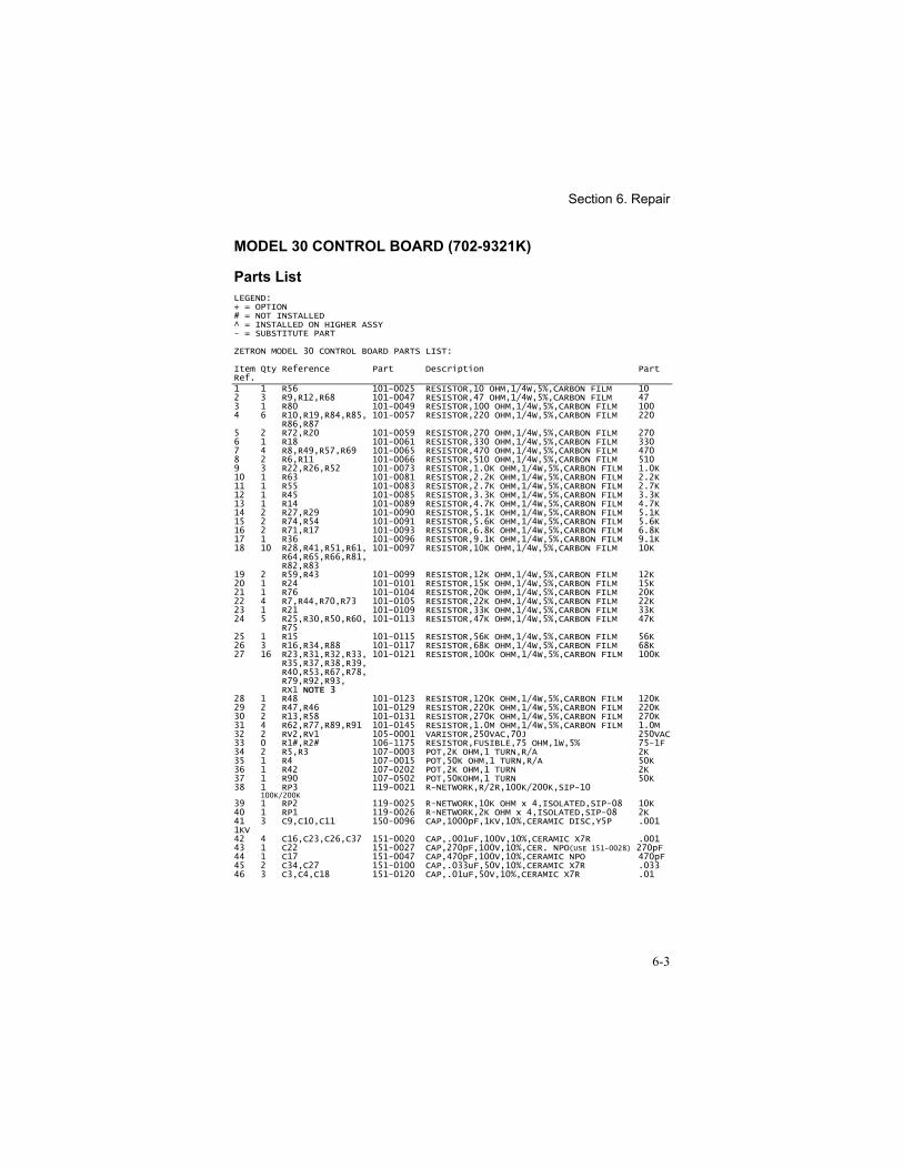
Section 6. Repair
6-3
MODEL 30 CONTROL BOARD (702-9321K)
Parts ListLEGEND:+ = OPTION# = NOT INSTALLED^ = INSTALLED ON HIGHER ASSY- = SUBSTITUTE PART
ZETRON MODEL 30 CONTROL BOARD PARTS LIST:
Item Qty Reference Part Description PartRef.1 1 R56 101-0025 RESISTOR,10 OHM,1/4W,5%,CARBON FILM 102 3 R9,R12,R68 101-0047 RESISTOR,47 OHM,1/4W,5%,CARBON FILM 473 1 R80 101-0049 RESISTOR,100 OHM,1/4W,5%,CARBON FILM 1004 6 R10,R19,R84,R85, 101-0057 RESISTOR,220 OHM,1/4W,5%,CARBON FILM 220
R86,R875 2 R72,R20 101-0059 RESISTOR,270 OHM,1/4W,5%,CARBON FILM 2706 1 R18 101-0061 RESISTOR,330 OHM,1/4W,5%,CARBON FILM 3307 4 R8,R49,R57,R69 101-0065 RESISTOR,470 OHM,1/4W,5%,CARBON FILM 4708 2 R6,R11 101-0066 RESISTOR,510 OHM,1/4W,5%,CARBON FILM 5109 3 R22,R26,R52 101-0073 RESISTOR,1.0K OHM,1/4W,5%,CARBON FILM 1.0K10 1 R63 101-0081 RESISTOR,2.2K OHM,1/4W,5%,CARBON FILM 2.2K11 1 R55 101-0083 RESISTOR,2.7K OHM,1/4W,5%,CARBON FILM 2.7K12 1 R45 101-0085 RESISTOR,3.3K OHM,1/4W,5%,CARBON FILM 3.3K13 1 R14 101-0089 RESISTOR,4.7K OHM,1/4W,5%,CARBON FILM 4.7K14 2 R27,R29 101-0090 RESISTOR,5.1K OHM,1/4W,5%,CARBON FILM 5.1K15 2 R74,R54 101-0091 RESISTOR,5.6K OHM,1/4W,5%,CARBON FILM 5.6K16 2 R71,R17 101-0093 RESISTOR,6.8K OHM,1/4W,5%,CARBON FILM 6.8K17 1 R36 101-0096 RESISTOR,9.1K OHM,1/4W,5%,CARBON FILM 9.1K18 10 R28,R41,R51,R61, 101-0097 RESISTOR,10K OHM,1/4W,5%,CARBON FILM 10K
R64,R65,R66,R81,R82,R83
19 2 R59,R43 101-0099 RESISTOR,12K OHM,1/4W,5%,CARBON FILM 12K20 1 R24 101-0101 RESISTOR,15K OHM,1/4W,5%,CARBON FILM 15K21 1 R76 101-0104 RESISTOR,20K OHM,1/4W,5%,CARBON FILM 20K22 4 R7,R44,R70,R73 101-0105 RESISTOR,22K OHM,1/4W,5%,CARBON FILM 22K23 1 R21 101-0109 RESISTOR,33K OHM,1/4W,5%,CARBON FILM 33K24 5 R25,R30,R50,R60, 101-0113 RESISTOR,47K OHM,1/4W,5%,CARBON FILM 47K
R7525 1 R15 101-0115 RESISTOR,56K OHM,1/4W,5%,CARBON FILM 56K26 3 R16,R34,R88 101-0117 RESISTOR,68K OHM,1/4W,5%,CARBON FILM 68K27 16 R23,R31,R32,R33, 101-0121 RESISTOR,100K OHM,1/4W,5%,CARBON FILM 100K
R35,R37,R38,R39,R40,R53,R67,R78,R79,R92,R93,RX1 NOTE 3
28 1 R48 101-0123 RESISTOR,120K OHM,1/4W,5%,CARBON FILM 120K29 2 R47,R46 101-0129 RESISTOR,220K OHM,1/4W,5%,CARBON FILM 220K30 2 R13,R58 101-0131 RESISTOR,270K OHM,1/4W,5%,CARBON FILM 270K31 4 R62,R77,R89,R91 101-0145 RESISTOR,1.0M OHM,1/4W,5%,CARBON FILM 1.0M32 2 RV2,RV1 105-0001 VARISTOR,250VAC,70J 250VAC33 0 R1#,R2# 106-1175 RESISTOR,FUSIBLE,75 OHM,1W,5% 75-1F34 2 R5,R3 107-0003 POT,2K OHM,1 TURN,R/A 2K35 1 R4 107-0015 POT,50K OHM,1 TURN,R/A 50K36 1 R42 107-0202 POT,2K OHM,1 TURN 2K37 1 R90 107-0502 POT,50KOHM,1 TURN 50K38 1 RP3 119-0021 R-NETWORK,R/2R,100K/200K,SIP-10
100K/200K39 1 RP2 119-0025 R-NETWORK,10K OHM x 4,ISOLATED,SIP-08 10K40 1 RP1 119-0026 R-NETWORK,2K OHM x 4,ISOLATED,SIP-08 2K41 3 C9,C10,C11 150-0096 CAP,1000pF,1KV,10%,CERAMIC DISC,Y5P .0011KV42 4 C16,C23,C26,C37 151-0020 CAP,.001uF,100V,10%,CERAMIC X7R .00143 1 C22 151-0027 CAP,270pF,100V,10%,CER. NPO(USE 151-0028) 270pF44 1 C17 151-0047 CAP,470pF,100V,10%,CERAMIC NPO 470pF45 2 C34,C27 151-0100 CAP,.033uF,50V,10%,CERAMIC X7R .03346 3 C3,C4,C18 151-0120 CAP,.01uF,50V,10%,CERAMIC X7R .01
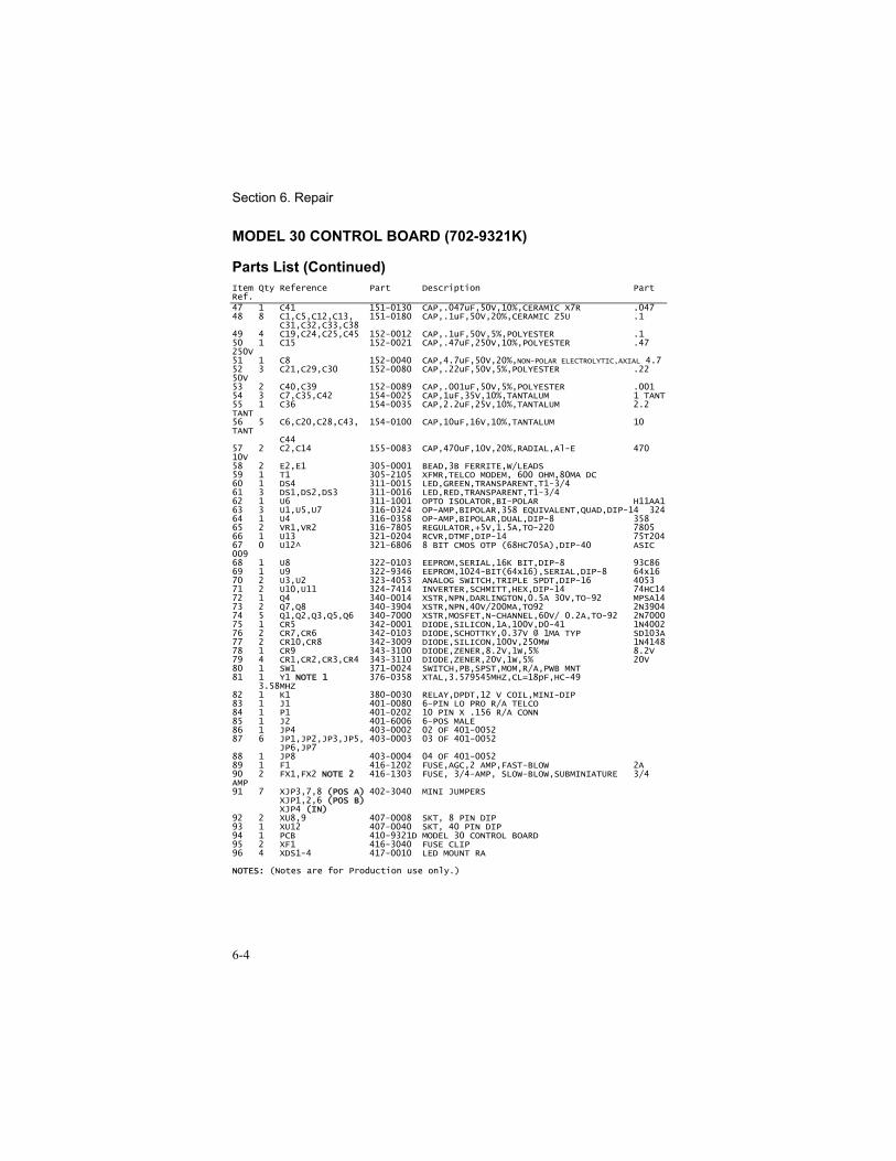
Section 6. Repair
6-4
MODEL 30 CONTROL BOARD (702-9321K)
Parts List (Continued)Item Qty Reference Part Description PartRef.47 1 C41 151-0130 CAP,.047uF,50V,10%,CERAMIC X7R .04748 8 C1,C5,C12,C13, 151-0180 CAP,.1uF,50V,20%,CERAMIC Z5U .1
C31,C32,C33,C3849 4 C19,C24,C25,C45 152-0012 CAP,.1uF,50V,5%,POLYESTER .150 1 C15 152-0021 CAP,.47uF,250V,10%,POLYESTER .47250V51 1 C8 152-0040 CAP,4.7uF,50V,20%,NON-POLAR ELECTROLYTIC,AXIAL 4.752 3 C21,C29,C30 152-0080 CAP,.22uF,50V,5%,POLYESTER .2250V53 2 C40,C39 152-0089 CAP,.001uF,50V,5%,POLYESTER .00154 3 C7,C35,C42 154-0025 CAP,1uF,35V,10%,TANTALUM 1 TANT55 1 C36 154-0035 CAP,2.2uF,25V,10%,TANTALUM 2.2TANT56 5 C6,C20,C28,C43, 154-0100 CAP,10uF,16V,10%,TANTALUM 10TANT
C4457 2 C2,C14 155-0083 CAP,470uF,10V,20%,RADIAL,Al-E 47010V58 2 E2,E1 305-0001 BEAD,3B FERRITE,W/LEADS59 1 T1 305-2105 XFMR,TELCO MODEM, 600 OHM,80MA DC60 1 DS4 311-0015 LED,GREEN,TRANSPARENT,T1-3/461 3 DS1,DS2,DS3 311-0016 LED,RED,TRANSPARENT,T1-3/462 1 U6 311-1001 OPTO ISOLATOR,BI-POLAR H11AA163 3 U1,U5,U7 316-0324 OP-AMP,BIPOLAR,358 EQUIVALENT,QUAD,DIP-14 32464 1 U4 316-0358 OP-AMP,BIPOLAR,DUAL,DIP-8 35865 2 VR1,VR2 316-7805 REGULATOR,+5V,1.5A,TO-220 780566 1 U13 321-0204 RCVR,DTMF,DIP-14 75T20467 0 U12^ 321-6806 8 BIT CMOS OTP (68HC705A),DIP-40 ASIC00968 1 U8 322-0103 EEPROM,SERIAL,16K BIT,DIP-8 93C8669 1 U9 322-9346 EEPROM,1024-BIT(64x16),SERIAL,DIP-8 64x1670 2 U3,U2 323-4053 ANALOG SWITCH,TRIPLE SPDT,DIP-16 405371 2 U10,U11 324-7414 INVERTER,SCHMITT,HEX,DIP-14 74HC1472 1 Q4 340-0014 XSTR,NPN,DARLINGTON,0.5A 30V,TO-92 MPSA1473 2 Q7,Q8 340-3904 XSTR,NPN,40V/200MA,TO92 2N390474 5 Q1,Q2,Q3,Q5,Q6 340-7000 XSTR,MOSFET,N-CHANNEL,60V/ 0.2A,TO-92 2N700075 1 CR5 342-0001 DIODE,SILICON,1A,100V,D0-41 1N400276 2 CR7,CR6 342-0103 DIODE,SCHOTTKY,0.37V @ 1MA TYP SD103A77 2 CR10,CR8 342-3009 DIODE,SILICON,100V,250MW 1N414878 1 CR9 343-3100 DIODE,ZENER,8.2V,1W,5% 8.2V79 4 CR1,CR2,CR3,CR4 343-3110 DIODE,ZENER,20V,1W,5% 20V80 1 SW1 371-0024 SWITCH,PB,SPST,MOM,R/A,PWB MNT81 1 Y1 NOTE 1 376-0358 XTAL,3.579545MHZ,CL=18pF,HC-49
3.58MHZ82 1 K1 380-0030 RELAY,DPDT,12 V COIL,MINI-DIP83 1 J1 401-0080 6-PIN LO PRO R/A TELCO84 1 P1 401-0202 10 PIN X .156 R/A CONN85 1 J2 401-6006 6-POS MALE86 1 JP4 403-0002 02 OF 401-005287 6 JP1,JP2,JP3,JP5, 403-0003 03 OF 401-0052
JP6,JP788 1 JP8 403-0004 04 OF 401-005289 1 F1 416-1202 FUSE,AGC,2 AMP,FAST-BLOW 2A90 2 FX1,FX2 NOTE 2 416-1303 FUSE, 3/4-AMP, SLOW-BLOW,SUBMINIATURE 3/4AMP91 7 XJP3,7,8 (POS A) 402-3040 MINI JUMPERS
XJP1,2,6 (POS B)XJP4 (IN)
92 2 XU8,9 407-0008 SKT, 8 PIN DIP93 1 XU12 407-0040 SKT, 40 PIN DIP94 1 PCB 410-9321D MODEL 30 CONTROL BOARD95 2 XF1 416-3040 FUSE CLIP96 4 XDS1-4 417-0010 LED MOUNT RA
NOTES: (Notes are for Production use only.)
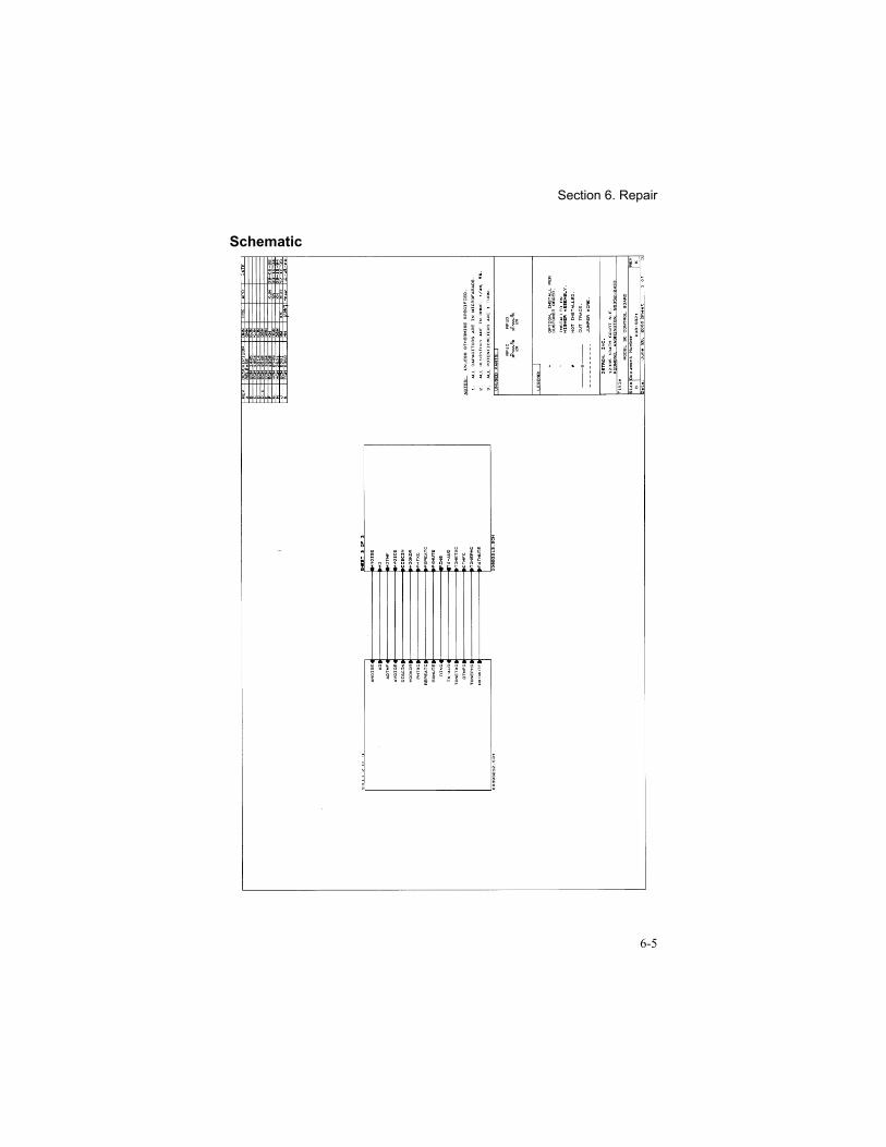
Section 6. Repair
6-5
Schematic
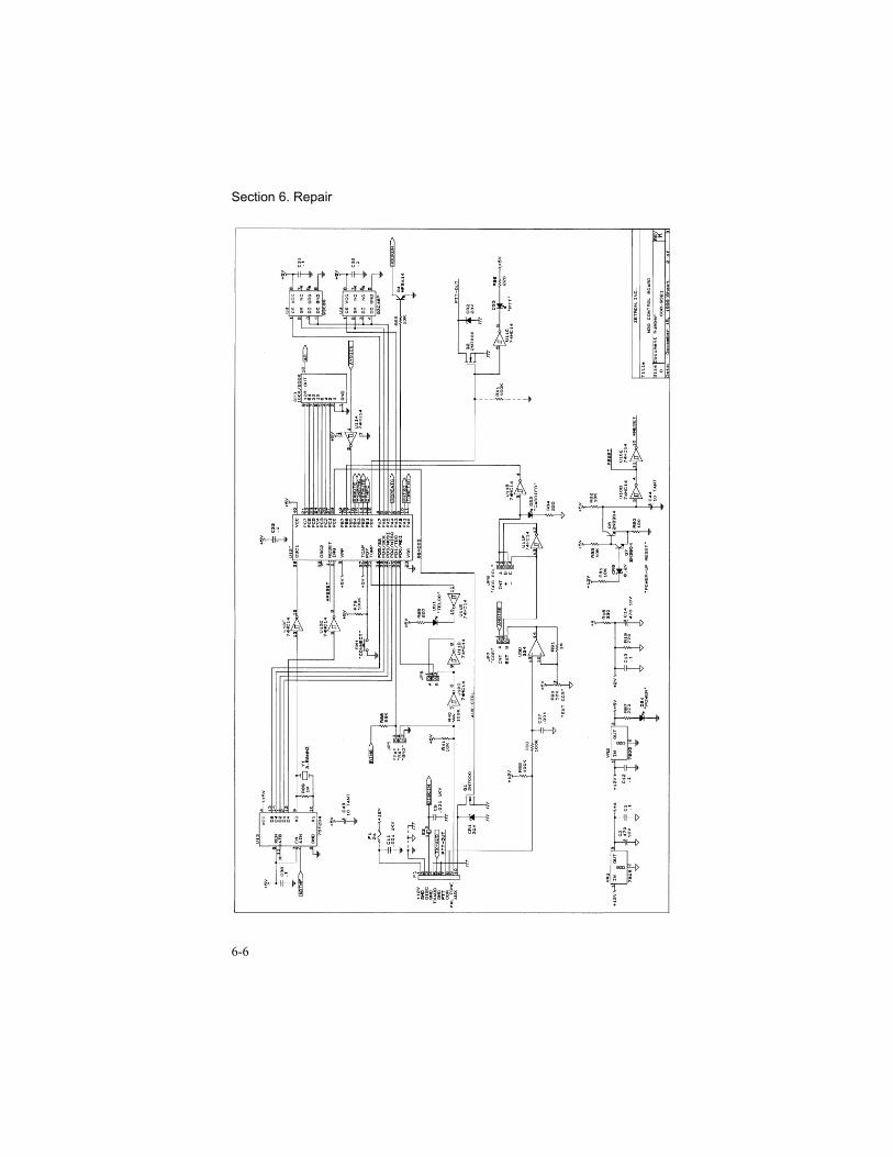
Section 6. Repair
6-6
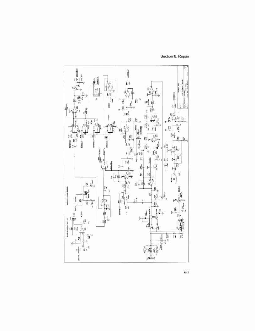
Section 6. Repair
6-7
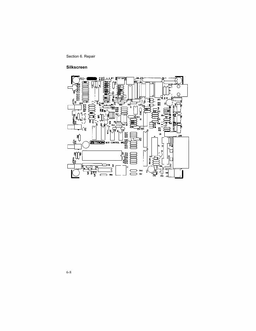
Section 6. Repair
6-8
Silkscreen
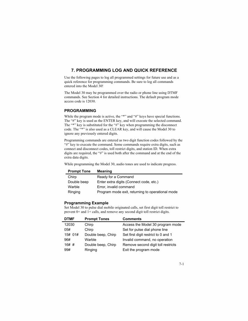
7-1
7. PROGRAMMING LOG AND QUICK REFERENCEUse the following pages to log all programmed settings for future use and as aquick reference for programming commands. Be sure to log all commandsentered into the Model 30!
The Model 30 may be programmed over the radio or phone line using DTMFcommands. See Section 4 for detailed instructions. The default program modeaccess code is 12030.
PROGRAMMINGWhile the program mode is active, the “*” and “#” keys have special functions.The “#” key is used as the ENTER key, and will execute the selected command.The “*” key is substituted for the “#” key when programming the disconnectcode. The “*” is also used as a CLEAR key, and will cause the Model 30 toignore any previously entered digits.
Programming commands are entered as two digit function codes followed by the“#” key to execute the command. Some commands require extra digits, such asconnect and disconnect codes, toll restrict digits, and station ID. When extradigits are required, the “#” is used both after the command and at the end of theextra data digits.
While programming the Model 30, audio tones are used to indicate progress.
Prompt Tone MeaningChirp Ready for a CommandDouble beep Enter extra digits (Connect code, etc.)Warble Error, invalid commandRinging Program mode exit, returning to operational mode
Programming ExampleSet Model 30 to pulse dial mobile originated calls, set first digit toll restrict toprevent 0+ and 1+ calls, and remove any second digit toll restrict digits.
DTMF Prompt Tones Comments12030 Chirp Access the Model 30 program mode05# Chirp Set for pulse dial phone line15# 01# Double beep, Chirp Set first digit restrict to 0 and 196# Warble Invalid command, no operation16# # Double beep, Chirp Remove second digit toll restricts99# Ringing Exit the program mode
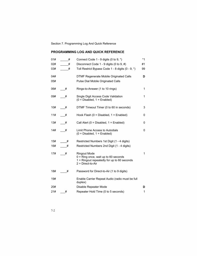
Section 7. Programming Log And Quick Reference
7-2
PROGRAMMING LOG AND QUICK REFERENCE
01# _____# Connect Code 1 - 9 digits (0 to 9, *) *102# _____# Disconnect Code 1 - 9 digits (0 to 9, #) #103# _____# Toll Restrict Bypass Code 1 - 8 digits (0 - 9, *) 99
04# DTMF Regenerate Mobile Originated Calls D05# Pulse Dial Mobile Originated Calls
06# ___# Rings-to-Answer (1 to 10 rings) 1
09# ___# Single Digit Access Code Validation(0 = Disabled, 1 = Enabled)
1
10# ___# DTMF Timeout Timer (0 to 60 in seconds) 3
11# ___# Hook Flash (0 = Disabled, 1 = Enabled) 0
13# ___# Call Alert (0 = Disabled, 1 = Enabled) 0
14# ___# Limit Phone Access to Autodials(0 = Disabled, 1 = Enabled)
0
15# ____# Restricted Numbers 1st Digit (1 - 4 digits)16# ____# Restricted Numbers 2nd Digit (1 - 4 digits)
17# ___# Ringout Mode0 = Ring once, wait up to 60 seconds1 = Ringout repeatedly for up to 60 seconds2 = Direct-to-Air
1
18# ____# Password for Direct-to-Air (1 to 9 digits)
19# Enable Carrier Repeat Audio (radio must be fullduplex)
20# Disable Repeater Mode D21# ___# Repeater Hold Time (0 to 5 seconds) 1
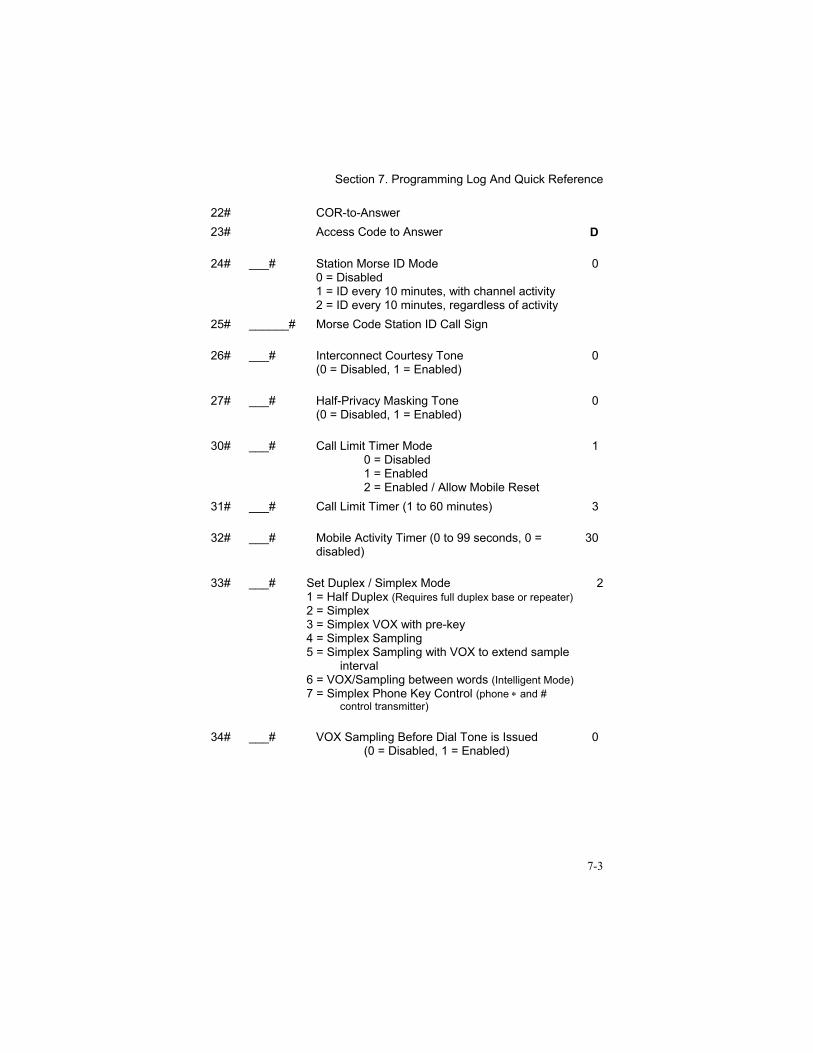
Section 7. Programming Log And Quick Reference
7-3
22# COR-to-Answer23# Access Code to Answer D
24# ___# Station Morse ID Mode0 = Disabled1 = ID every 10 minutes, with channel activity2 = ID every 10 minutes, regardless of activity
0
25# ______# Morse Code Station ID Call Sign
26# ___# Interconnect Courtesy Tone(0 = Disabled, 1 = Enabled)
0
27# ___# Half-Privacy Masking Tone(0 = Disabled, 1 = Enabled)
0
30# ___# Call Limit Timer Mode0 = Disabled1 = Enabled2 = Enabled / Allow Mobile Reset
1
31# ___# Call Limit Timer (1 to 60 minutes) 3
32# ___# Mobile Activity Timer (0 to 99 seconds, 0 =disabled)
30
33# ___# Set Duplex / Simplex Mode1 = Half Duplex (Requires full duplex base or repeater)2 = Simplex3 = Simplex VOX with pre-key4 = Simplex Sampling5 = Simplex Sampling with VOX to extend sample
interval6 = VOX/Sampling between words (Intelligent Mode)7 = Simplex Phone Key Control (phone ∗ and #
control transmitter)
2
34# ___# VOX Sampling Before Dial Tone is Issued(0 = Disabled, 1 = Enabled)
0
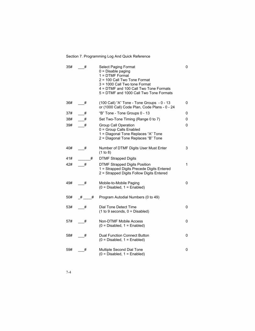
Section 7. Programming Log And Quick Reference
7-4
35# ___# Select Paging Format0 = Disable paging1 = DTMF Format2 = 100 Call Two Tone Format3 = 1000 Call Two tone Format4 = DTMF and 100 Call Two Tone Formats5 = DTMF and 1000 Call Two Tone Formats
0
36# ___# (100 Call) “A” Tone - Tone Groups - 0 - 13or (1000 Call) Code Plan, Code Plans - 0 - 24
0
37# ___# “B” Tone - Tone Groups 0 - 13 038# ___# Set Two-Tone Timing (Range 0 to 7) 039# ___# Group Call Operation
0 = Group Calls Enabled1 = Diagonal Tone Replaces “A” Tone2 = Diagonal Tone Replaces “B” Tone
0
40# ___# Number of DTMF Digits User Must Enter(1 to 8)
3
41# ______# DTMF Strapped Digits42# ___# DTMF Strapped Digits Position
1 = Strapped Digits Precede Digits Entered2 = Strapped Digits Follow Digits Entered
1
49# ___# Mobile-to-Mobile Paging(0 = Disabled, 1 = Enabled)
0
50# _# ____# Program Autodial Numbers (0 to 49)
53# ___# Dial Tone Detect Time(1 to 9 seconds, 0 = Disabled)
0
57# ___# Non-DTMF Mobile Access(0 = Disabled, 1 = Enabled)
0
58# ___# Dual Function Connect Button(0 = Disabled, 1 = Enabled)
0
59# ___# Multiple Second Dial Tone(0 = Disabled, 1 = Enabled)
0
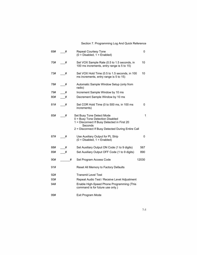
Section 7. Programming Log And Quick Reference
7-5
69# ___# Repeat Courtesy Tone(0 = Disabled, 1 = Enabled)
0
70# ___# Set VOX Sample Rate (0.5 to 1.5 seconds, in100 ms increments, entry range is 5 to 15)
10
73# ___# Set VOX Hold Time (0.5 to 1.5 seconds, in 100ms increments, entry range is 5 to 15)
10
78# ___# Automatic Sample Window Setup (only fromradio)
79# ___# Increment Sample Window by 10 ms80# ___# Decrement Sample Window by 10 ms
81# ___# Set COR Hold Time (0 to 500 ms, in 100 msincrements)
0
85# ___# Set Busy Tone Detect Mode0 = Busy Tone Detection Disabled1 = Disconnect If Busy Detected in First 20
Seconds2 = Disconnect If Busy Detected During Entire Call
1
87# ___# Use Auxiliary Output for PL Strip(0 = Disabled, 1 = Enabled)
0
88# ___# Set Auxiliary Output ON Code (1 to 9 digits) 56789# ___# Set Auxiliary Output OFF Code (1 to 9 digits) 890
90# ______# Set Program Access Code 12030
91# Reset All Memory to Factory Defaults
92# Transmit Level Test93# Repeat Audio Test / Receive Level Adjustment94# Enable High-Speed Phone Programming (This
command is for future use only.)
99# Exit Program Mode
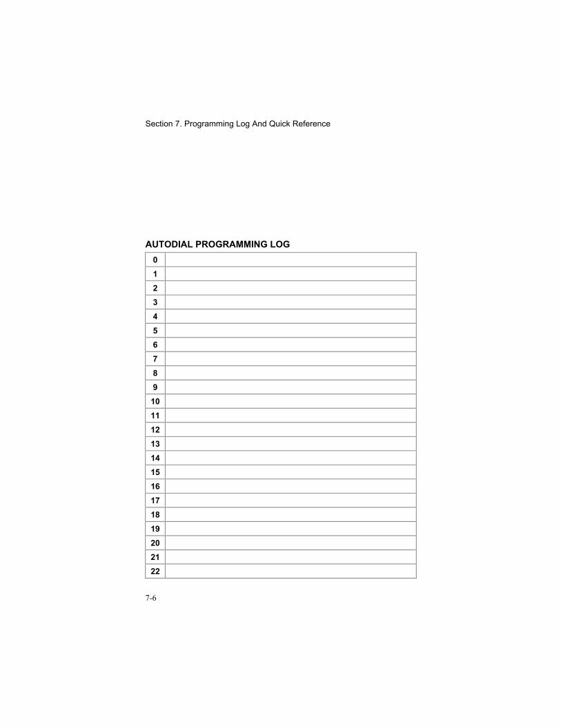
Section 7. Programming Log And Quick Reference
7-6
AUTODIAL PROGRAMMING LOG012345678910111213141516171819202122
Section 7. Programming Log And Quick Reference
7-7
232425262728293031323334353637383940414243444546474849

Section 7. Programming Log And Quick Reference
7-8