zevenhoven & kilpinen cross effects, total...
TRANSCRIPT

Zevenhoven & Kilpinen CROSS EFFECTS, TOTAL SYSTEM LAY-OUT 13.6.2001 10-1
Figure 10.1 Typical pulverised coal combustion and gas clean-up system: dry scrubber +baghouse filter for SO2 and particulate control (picture from Stultz and Kitto, 1992)
Chapter 10 Cross effects andtotal gas clean-upsystem lay-out
10.1 Introduction
Often more than one pollutant has to be removed from a flue gas or fuel gas. Forpower plants the emission regulations are usually less strict than for wasteincinerators, for example, and less species have to be controlled at a typical powerplant (typically only SO2, NOx and particulates) than for flue gases from wasteincineration. Also for a certain species such as SO2 or NOx the emissions regulationsdepend on process type and plant size. Some compounds such as alkali or chlorinemay not be of any concern from an emissions point of view but are controlled toprevent corrosion, damages to process equipment or operational problems in general.In other cases the gas is a product that has to fulfill certain specifications, such as amaximum concentration of 2.5%-vol CO2 in natural gases. For the process economypriorities can be ranked as 1) emission regulations or fuel gas quality requirements,2) process operation and plant life and 3) thermal power efficiency.

Zevenhoven & Kilpinen CROSS EFFECTS, TOTAL SYSTEM LAY-OUT 13.6.2001 10-2
Whatever the situation, when more than one piece of equipment must be installed thequestion arises of how to arrange the equipment. Although the answer partly followsfrom the temperature profile of the process, the interactions between the emissionscontrol steps play an important role as well. These issues are discussed briefly in thislast chapter, excluding the greenhouse gas CO2 (7 chapter 9).
10.2 Gas clean-up for power plants
For a conventional pulverised coal-fired power plant a set-up is shown in Figure 10.1,with a gas clean-up system composed of a dry sorbent injection + baghouse filterarrangement for SO2 and particulate control. For solid fuel -, oil - or gas - fired powerplants typical positioning of gas clean-up devices is given in Table 10.1. Whatequipment is needed depends on fuel quality, local regulations and process type.
Table 10.1 Typical positioning of flue gas or fuel gas clean-up equipment for power plants
Furnace > 400EEC 200 - 400EEC < 200EEC
Gas firedfurnace orengine or NGCC*
Flue gasrecirculation,
water injection,reburning fuel
SNCR SCR
Oil fired furnaceor engine
Flue gasrecirculation,
water injection,reburning fuel
SNCR SCR, (semi-) dryFGD
wet FGD
Pulverised fuel furnace
Reburning fuel,furnace sorbentinjection FGD
SNCR SCR, hot ESP,duct sorbent
injection FGD
cold-side ESP,baghouse filter,
wet FGD,
AFBC /PFBC-CC**
Ca-based sorbent,reburning fuel
cyclone, SNCR SCR, hot ESP cold-side ESP,baghouse filter
IGCC for solidfuels
Ca-based sorbent tar cracking, hotgas filter, alkali,
halogen removal,H2S/COS
removal, NH3
removal ***
SCR
* Natural gas-fired combined cycle** For PFBC-CC : expansion turbine after cyclone or cyclone + SNCR*** All upstream of the gas turbine combustion chamber

Zevenhoven & Kilpinen CROSS EFFECTS, TOTAL SYSTEM LAY-OUT 13.6.2001 10-3
Furnace and boiler Temperature (C) Flue ga s clean -up Temperature (C)
1 Primary combust ion chamber 260 - 800 4 Elec trostatic precipitator 180 -300
2 Secondary combust ion chamber 800 - 1200 5 H C l scrubber (pH ~ 1) 60 - 70
3 H eat recovery boiler 600 - 800 6 S O 2 scrubber (pH ~ 6 ) 60 - 70
7 Re-heater 350 - 400
8 S C R D e N O x 300 - 400
9 Ac tive coke bed 100 - 150
Figure 10.2 Lay-out of a modern solid waste incinerator facility with gas clean-up (picture fromKrupp VDM, 1999)
For natural gas firing the only species of concern is NOx, for oil firing SO2 may needattention as well. For solid fuels dust, SO2 (except for biomass fuels) and NOxemissions must be controlled. Solid fuel-fired IGCC processes involve hot gas clean-up to upgrade the fuel gas to gas turbine inlet specifications. It is expected thataround 2005 mercury (Hg) emissions will be regulated as well for power plants.
10.3 Gas clean-up for flue gases from waste incineration and cement plants
For waste incineration a rather wide range of pollutants must be controlled. Thecomposition of most wastes is characterised by high concentrations of halogen(mainly chlorine in the form of PVC) and trace elements. Furthermore, the burningprocess typically results in significant VOC and PAH emissions due to the relativelylarge “fuel” size and mixing limitations. Particulates are the first to be removed fromthe flue gas, as to remove the most concentrated pollutant first and to protect gasclean-up equipment downstream. As the lay-out for a modern waste incinerator inFigure 10.2 shows, reheat is needed for the DeNOx SCR device operated at 350-400EC. This is then followed by activated carbon (as a bed or injected as powder),after part of some species such as PAHs, PCDD/Fs may have been destroyed alreadyby oxidation in the SCR. Table 10.2 lists the positioning of control devices in a wasteincinerator flue gas clean-up train.
Zevenhoven & Kilpinen CROSS EFFECTS, TOTAL SYSTEM LAY-OUT 13.6.2001 10-4
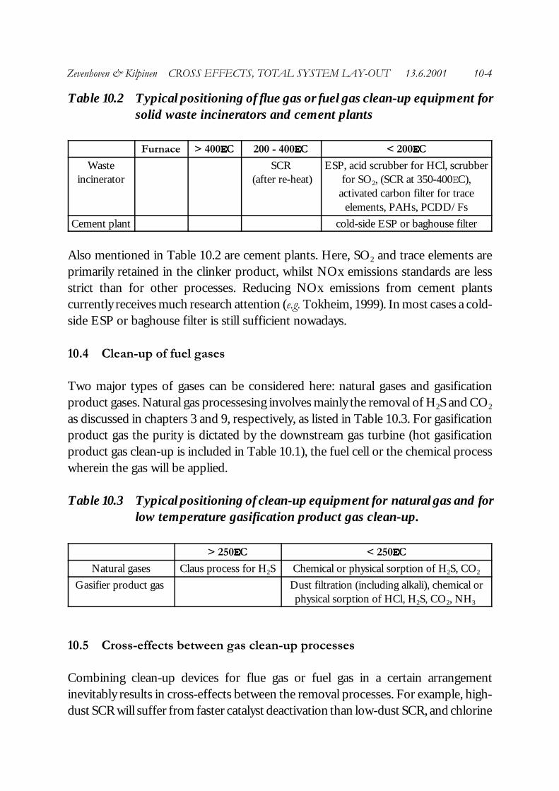
Table 10.2 Typical positioning of flue gas or fuel gas clean-up equipment forsolid waste incinerators and cement plants
Furnace > 400EEC 200 - 400EEC < 200EEC
Wasteincinerator
SCR (after re-heat)
ESP, acid scrubber for HCl, scrubberfor SO2, (SCR at 350-400EC),
activated carbon filter for traceelements, PAHs, PCDD/Fs
Cement plant cold-side ESP or baghouse filter
Also mentioned in Table 10.2 are cement plants. Here, SO2 and trace elements areprimarily retained in the clinker product, whilst NOx emissions standards are lessstrict than for other processes. Reducing NOx emissions from cement plantscurrently receives much research attention (e.g. Tokheim, 1999). In most cases a cold-side ESP or baghouse filter is still sufficient nowadays.
10.4 Clean-up of fuel gases
Two major types of gases can be considered here: natural gases and gasificationproduct gases. Natural gas processesing involves mainly the removal of H2S and CO2
as discussed in chapters 3 and 9, respectively, as listed in Table 10.3. For gasificationproduct gas the purity is dictated by the downstream gas turbine (hot gasificationproduct gas clean-up is included in Table 10.1), the fuel cell or the chemical processwherein the gas will be applied.
Table 10.3 Typical positioning of clean-up equipment for natural gas and forlow temperature gasification product gas clean-up.
> 250EEC < 250EEC
Natural gases Claus process for H2S Chemical or physical sorption of H2S, CO2
Gasifier product gas Dust filtration (including alkali), chemical orphysical sorption of HCl, H2S, CO2, NH3
10.5 Cross-effects between gas clean-up processes
Combining clean-up devices for flue gas or fuel gas in a certain arrangementinevitably results in cross-effects between the removal processes. For example, high-dust SCR will suffer from faster catalyst deactivation than low-dust SCR, and chlorine
Zevenhoven & Kilpinen CROSS EFFECTS, TOTAL SYSTEM LAY-OUT 13.6.2001 10-5
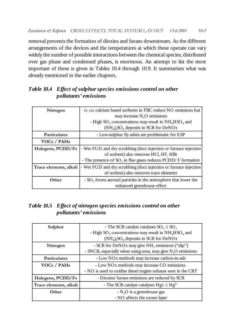
removal prevents the formation of dioxins and furans downstream. As the differentarrangements of the devices and the temperatures at which these operate can varywidely the number of possible interactions between the chemical species, distributedover gas phase and condensed phases, is enormous. An attempt to list the mostimportant of these is given in Tables 10.4 through 10.9. It summarises what wasalready mentioned in the earlier chapters.
Table 10.4 Effect of sulphur species emissions control on otherpollutants’ emissions
Nitrogen - In situ calcium based sorbents in FBC reduce NO emissions butmay increase N2O emissions
- High SO2 concentrations may result in NH4HSO4 and(NH4)2SO4 deposits in SCR for DeNOx
Particulates - Low-sulphur fly ashes are problematic for ESP
VOCs / PAHs
Halogens, PCDD/Fs - Wet FGD and dry scrubbing (duct injection or furnace injectionof sorbent) also removes HCl, HF, HBr
- The presence of SO2 in flue gases reduces PCDD/F formation
Trace elements, alkali - Wet FGD and dry scrubbing (duct injection or furnace injectionof sorbent) also removes trace elements
Other - SO2 forms aerosol particles in the atmosphere that lower theenhanced greenhouse effect
Table 10.5 Effect of nitrogen species emissions control on otherpollutants’ emissions
Sulphur - The SCR catalyst catalyses SO2 6 SO3
- High SO2 concentrations may result in NH4HSO4 and(NH4)2SO4 deposits in SCR for DeNOx
Nitrogen - SCR for DeNOx may give NH3 emissions (“slip”)- SNCR, especially when using urea, may give N2O emissions
Particulates - Low NOx methods may increase carbon-in-ash
VOCs / PAHs - Low NOx methods may increase CO emissions - NO is used to oxidise diesel engine exhaust soot in the CRT
Halogens, PCDD/Fs - Dioxins/furans emissions are reduced by SCR
Trace elements, alkali - The SCR catalyst catalyses HgE 6 Hg2+
Other - N2O is a greenhouse gas- NO affects the ozone layer

Zevenhoven & Kilpinen CROSS EFFECTS, TOTAL SYSTEM LAY-OUT 13.6.2001 10-6
Table 10.6 Effect of particultate emissions control on otherpollutants’ emissions
Sulphur - Ash particles possibly catalyse SO2 6 SO3
- Fly ash in a wet FGD scrubbers: deposits, low quality gypsum
Nitrogen - Hot-side ESPs before SCR for DeNOx protects the catalyst
VOCs / PAHs
Halogens, PCDD/Fs - Removing particles removes also possible catalysts for theDeacon reaction and possible dioxin/furan formation
Trace elements, alkali - ESPs remove most Class I + II trace elements, some Class III
Other - Cyclones before an ESP or filter may save costs
Table 10.7 Effect of VOC/PAH species emissions control on otherpollutants’ emissions
Sulphur
Nitrogen - PAHs may foul, poison, i.e. deactivate SCR catalysts
Particulates
Halogens, PCDD/Fs - VOCs and PAHs participate in dioxin/furan formation
Trace elements, alkali - VOCs and PAHs may be also adsorbed on activated carbon
Other - VOC control reduces ground-level ozone- PAHs may foul, poison, i.e. deactivate VOC oxidation catalysts
Table 10.8 Effect of halogen species and PCDD/F emissions control onother pollutants’ emissions
Sulphur - HF may give ALFx deposit formation in wet FGD- HCl, HBr and HF will lower the pH in FGD which negatively
affects sulphur capture performance
Nitrogen
Particulates - HF attacks silicates, for example in filter bags
VOCs / PAHs
Trace elements, alkali - HCl and Cl2 removal gives less volatile trace element chlorides
Other - HCl and Cl2 removal blocks dioxin/furan formation- Chlorine and other halogens hinder CO burnout

Zevenhoven & Kilpinen CROSS EFFECTS, TOTAL SYSTEM LAY-OUT 13.6.2001 10-7
Table 10.9 Effect of trace elements and alkali emissions control on otherpollutants’ emissions
Sulphur - Removal of vanadium, for example, blocks SO2 6 SO3
- Na2S4 for Hg trapping in HCl scrubber may give some H2S
Nitrogen - Vanadium oxide may act as an SCR catalyst
Particulates
VOCs / PAHs - Nickel is an active tar cracking catalyst- Some trace elements limit soot formation
Halogens, PCDD/Fs
Other - Activated carbon may adsorb other species- Trace metals like Mn and Cr may bind mercury
10.6 References
Krupp VDM (1999?) “Thermische Abfallverwertung - Verfahren - Werkstoffe - Case Histories”Krupp VDM , Werdohl (Germany)
Stultz, S,C, Kitto, J.B. (1992) “Steam - Its generation and use” (40th ed.) Babcock and Wilcox Co.,Barberton (OH)
Tokheim, L.-E. (1999) “The impact of staged combustion on the operation of a precalciner cementkiln” PhD thesis NTNU Trondheim, Telemark College University, Porsgrunn (Norway)

Zevenhoven & Kilpinen CROSS EFFECTS, TOTAL SYSTEM LAY-OUT 13.6.2001 10-8