zhorif ikmal bin zahari mohamad akmal bin ...persatuan pelajar kejuruteraan mekanikal universiti...
TRANSCRIPT

Persatuan Pelajar Kejuruteraan Mekanikal
Universiti Teknologi Malaysia
Kuala Lumpur
ZHORIF IKMAL BIN ZAHARIMOHAMAD AKMAL BIN ISHAKNUR AZIMAH BINTI AHMAD KAMALNURUL FATIHA SHAHIRA BINTI MOHD ZULKIFLI

CONTENT INTRODUCTION
OBJECTIVE
PROBLEM STATEMENT
LITERATURE REVIEW
DESIGN METHOD
TECHNICAL DRAWING
FABRICATION PROCESS
ANALYSIS
DISCUSSION
CONCLUSION

INTRODUCTION• The Pico Hydro is a term used for hydroelectric power generation of under five
kilowatts (5kW). Hydro power system of this size benefit in terms of simplicity from different approaches in the design, planning and installation than those which are applied to larger hydro power.
• It is useful in small, remote communities that require only a small amount of electricity for example, to power one or two fluorescent light bulbs and a TV or radio in 50 or so homes. Even smaller turbines of 200-300 Watts (W) may power a single home in a developing country with a drop of only one meter.
• Pico-hydro setups typically are run-of-stream, meaning that a reservoir of water is not created, only a small weir is common, pipes divert some of the flow, drop this down a gradient and through the turbine before being exhausted back to the stream.
• Like other hydroelectric and renewable source power generation, pollution and consumption of fossil fuels is reduced, though there is still typically environmental cost to the manufacture of the generator and distribution methods.

OBJECTVE
The aim of this study is to generate electricity by using a pico hydro
current turbine. The objectives are as follows:
1. To study the literature review.
2. To analyse theoretically.
3. To design a pico hydro water turbine.
4. To test the prototype in fluid lab.

PROBLEM STATEMENT
• The disadvantages of the H-Darrieus rotor is it has reverse force on the returning blade and it will make the burden for the rotor to rotate.
• Darrieus also has a drawback of low starting torque.
• As we built for the small scale electrical generation, we are only targeting for rural areas.
• Rural electrification is often considered to be the backbone of the rural economy.

.
• Development of rural electrification
• In today's context, rural electrification has five major facets:-
1. Setting up of rural electricity infrastructure
2. Providing connectivity to households
3. Adequate supply of desired quality of power
4. Supply of electricity at affordable rates
5. Providing clean, environmentally benign and sustainable
power in efficient way
LITERATURE REVIEW
Hydro power Technology system have two criteria classification:
1. Technology
- dammed reservoir, run of river, in stream, pumper storage, vortex
power
2. Capacity
-larger hydro,smaller hydro, micro hydro, pico hydro

Components of turbine system
1. Turbine
Turbine is the main parts in the pico hydro system, where the task is to
convert water power to rational force in order to derive generator. It is
important to select the right turbine as most of the losses are due to this
component
2. Transmission
The spur gear of a car and car shaft were used for
rotational transmission to increase the rotational speed.
Circular plate adapters were attached to the spur gear and the shaft by
bolts.

3. Generator
An alternator removed from a scrapped car, widely available in Malaysia
was used as the generator. Car alternators are designed to generate 100-200 W
of power comparably low rational speeds (<1200 rpm). Thus car alternators
are suitable for pico hydro systems with open waterwheels, which run at low
rotational speeds and have a low power output

Type of turbine system
Vertical axis turbine
SavoniusWater
turbine
Darrieuswater turbine
Helical water turbine
Horizontal turbine system
Crossflowturbine

DESIGN METHOD
• There are a few designs of Pico Hydro
Water Current Water Turbine.
• Main Ideas and initial designs:
• 1.
• Use hydraulic fluid in vane pumps.
• Pulley and timing belt – Transmit power to alternator.
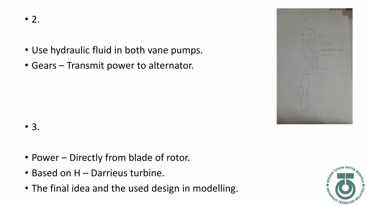
• 2.
• Use hydraulic fluid in both vane pumps.
• Gears – Transmit power to alternator.
• 3.
• Power – Directly from blade of rotor.
• Based on H – Darrieus turbine.
• The final idea and the used design in modelling.
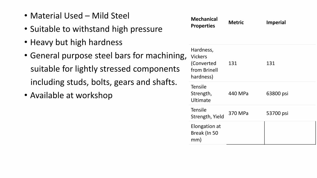
• Material Used – Mild Steel
• Suitable to withstand high pressure
• Heavy but high hardness
• General purpose steel bars for machining,
suitable for lightly stressed components
including studs, bolts, gears and shafts.
• Available at workshop
Mechanical Properties
Metric Imperial
Hardness, Vickers (Converted from Brinellhardness)
131 131
Tensile Strength, Ultimate
440 MPa 63800 psi
Tensile Strength, Yield
370 MPa 53700 psi
Elongation at Break (In 50 mm)

TECHNICAL DRAWING


FABRICATION PROCEDURE
*Cutting *Welding *Drilling

*Grinding *Lathe Machine

ANALYSIS
Velocity (m/s)
Area of Rotor(m2)
Cp Power Generated(kW)
Power Mechanical
(kW)
Power Losses(kW)
0.23 1.51 0.55 5 9.26 4.26
0.24 1.51 0.48 5 10.42 5.42
0.25 1.51 0.42 5 11.80 6.80


DISCUSSION
From the graph plotted in figure 4.3.1, velocity value is increased with the
increasing of Cp value because speed of the water was changed by the rotational
speed of rotor. From figure 4.3.2, velocity value is increase by with the
increasing of power mechanical value. This is because the torque of the shaft of
the rotor is increased affected by the increasing of the velocity of the river flow.
From figure 4.3.3, power mechanical value is increasing directly proportional to
power losses value.

CONCLUSION
• It can be concluded that higher power output can be generated with the help of
greater water velocity or in this case, river velocity. This is due to the pressure of
water increases the velocity of the water flowing through the rotor. Besides that,
based on the equation of power generated, the pressure of the water also affected
the output power of the system. Moreover, due to high velocity of the water, it
made the rotor of the turbine rotate faster and it can generate more output power.

• Lastly, from the designed rotor view, the H-Darrieus with deflectors were able to
generate more output power and gave more speed compared to traditional H-Darrieus
turbine. With addition of deflectors, the turbine was able to increase drag force on the
rotor when water stroked on its blade and the addition of H-Darrieus blade it gave more
lift force on the rotor. The deflector was an important role on this project to generate
more output power. The conclusion is made based on theoretical analysis. The turbine
was made only as a prototype, it satisfies the H-Darrieus concept stated before but due to
lack of time, we did not managed to bring this project to test it on the river. We only
managed to calculate the possible outcome by using theory analysis.

APPENDIX


THANK YOU!