zigbee-based smart home system nurul ilmi binti …eprints.utem.edu.my/16553/1/zigbee-based smart...
TRANSCRIPT

ZIGBEE-BASED SMART HOME SYSTEM
NURUL ILMI BINTI OMAR
This report is submitted in partial fulfillment of the requirement for the Bachelor Degree
in Electronic Engineering (Wireless Communication) with Honors
Faculty of Electronic and Computer Engineering
University Technical Malaysia Melaka
June 2014

UNIVERSTI TEKNIKAL MALAYSIA MELAKA
FAKULTI KEJURUTERAAN ELEKTRONIK DAN KEJURUTERAAN KOMPUTER
BORANG PENGESAHAN STATUS LAPORAN
PROJEK SARJANA MUDA II
Tajuk Projek :
Sesi Pengajian :
Saya NURUL ILMI BINTI OMAR mengaku membenarkan Laporan Projek Sarjana Muda ini disimpan di Perpustakaan dengan syarat-syarat kegunaan seperti berikut: 1. Laporan adalah hakmilik Universiti Teknikal Malaysia Melaka.
2. Perpustakaan dibenarkan membuat salinan untuk tujuan pengajian sahaja.
3. Perpustakaan dibenarkan membuat salinan laporan ini sebagai bahan pertukaran antara institusi
pengajian tinggi.
4. Sila tandakan ( √ ) :
SULIT*
*(Mengandungi maklumat yang berdarjah keselamatan atau kepentingan Malaysia seperti yang termaktub di dalam AKTA RAHSIA RASMI 1972)
TERHAD**
**(Mengandungi maklumat terhad yang telah ditentukan oleh organisasi/badan di mana penyelidikan dijalankan)
TIDAK TERHAD
Disahkan oleh:
__________________________ ___________________________________
(TANDATANGAN PENULIS) (COP DAN TANDATANGAN PENYELIA)
ZIGBEE-BASED SMART HOME SYSTEM
2013/2014

“I hereby declare that this report is the result of my own work except for quotes as cited
in the references.”
Signature :…………………………….....
Author : NURUL ILMI BINTI OMAR
Date :…………………….................

“I hereby declare that I have read through this report entitled “ZigBee-Based Smart
Home System” and found that it is enough in terms of scope and quality and has
complied the partial fulfillment for the awarding of the Bachelor of Electronics
Engineering (Communication Wireless).”
Signature : …………………………………………..
Supervisor : ENGR. NOOR BADARIAH BTE ASAN
DATE : …………………………………………...
v
DEDICATION
Dedicated to my beloved father, mother and families

vi
ACKNOWLEDGMENT
Alhamdulillah, praise to Allah S.W.T for the guidance and blessing upon me, for
without it I would not have been able to come this far.
I wish to give my appreciation to my supervisors Engr. Noor Badariah bte Asan
for their advice, understanding, good guidance and help throughout this project. Without
their valuable suggestions and encouragement, this project would have not been
successful.
A special thanks to my family especially my parents who encouraged me in my
final year here and gives me lots of inspiration. Last but not least, to all my fellow
friends for their brilliant ideas, support and encouragement throughout the duration of
this project. Thank you so much.

vii
ABSTRACT
Wireless technology has already become an important application which usually
integrated to a wide range of device and other technologies. The enhancements provide
by the wireless technology gives the ease of control to the users. Nowadays, almost all
the electronic devices are equipped with wireless technology. This fact shows the
necessity and benefits provide by this technology. This project is mainly concern about
home power consumption observation system with wireless capabilities. It is use the X-
Bee as the wireless modules. This project uses two microcontrollers to handle the
wireless communication protocol. The first microcontroller done the calculation needed
and display it to the user with both hardware and software interface. The second
microcontroller functions as the watch guard for the sensor circuit. The received data
from sensor circuit is stored and send to the first microcontroller upon request.
Moreover, the user interfaces gives ease of controls to the users. Furthermore, this
system also has the interconnecting with Wireless Sensor Network (WSN) such as the
IEEE802.15.4 ZigBee Protocol.

viii
ABSTRAK
Teknologi wayarles telah menjadi aplikasi penting yang biasanya terintegrasi
untuk peranti dan teknologi lain. Alat tambahan mempunyai teknologi wayarles
memberikan kemudahan kawalan kepada pengguna. Kini, hampir semua peranti
elektronik dilengkapi dengan teknologi wayarles. Fakta ini menunjukkan betapa
pentingnya teknologi ini. Projek ini berkaitan system pengawasan, penggunaan kuasa
dirumah dengan kemampuan wayarles. Sistem ini menggunakan X-Bee sebagai modul
wayarles. Projek ini menggunakan dua mikropengawal untuk menangani protokol
komunikasi wayarles. Mikropengawal pertama melakukan pengiraan yang diperlukan
dan mempamerkannya kepada pengguna dengan antara muka peranti keras dan perisian.
Fungsi mikropengawal kedua sebagai mengawasi litar pengesan. Data yang diterima
daripada litar pengesan tersebut disimpan dan dihantar ke mikropengawal pertama atas
permintaan. Dengan kemudahan antara muka, sistem ini memberikan kemudahan bagi
pengguna untuk berkomunikasi dengan sistem ini. Selanjutnya, sistem ini juga
mempunyai interaksi dengan teknologi pengesan wayarles seperti IEEE802.15.4 ZigBee
Protokol.

ix
TABLE OF CONTENTS
CHAPTER CONTENT PAGE
PROJECT TITLE i
BORANG PENGESAHAN STATUS LAPORAN ii
REPORT ACKNOWLEDGEMENT FORM iii
STUDENT DECLARATION FORM iv
SUPERVISOR DECLARATION PAGE v
DEDICATION vi
ACKNOWLEDGMENT vii
ABSTRACK viii
TABLE OF CONTENT ix
LIST OF TABLE xii
LIST OF FIGURE xiii
LIST OF ABBREVIATIONS xv
1 INTRODUCTION
1.0 Overview 1
1.1 Project Background 1
1.2 Overview of Project 2
1.3 Problem Statement 2
1.4 Objective of Project 3
1.5 Scope of Project 3
1.6 Project Methodology 6

x
1.7 Project Structure 7
2 LITERATURE REVIEW
2.0 Chapter Overview 9
2.1 Previous Project 10
2.2 Hardware and Theory 19
2.3 Software and Theory 24
3 PROJECT METHODOLOGY
3.0 Review of Project Methodology 27
3.1 Introduction 27
3.2 Process of Project 28
3.3 Preparation of Printed Circuit Boards 31
4 CONCLUSION
4.0 Introduction 36
4.1 Implementation 36
4.2 Simulation Result 38
4.3 Hardware Development 38
4.4 Software Development 40
4.5 Analysis Result 48

xi
5 CONCLUSION AND RECOMMENDATION
5.0 Conclusion 50
5.1 Recommendation 51
REFERENCES 52
APPENDIX A 54
APPENDIX B 57
APPENDIX C 60

xii
LIST OF TABLE
TABLE TITLE PAGE
2.1 Wireless Standard 22
2.2 Long Range Data Integrity 23
2.3 Low Power of X-Bee 23
4.1 Analysis distance of X-Bee between the Residential 49
Areas and Security Post

xiii
LIST OF FIGURE
FIGURE TITLE PAGE
1.1 Scope of Project 5
1.2 Block Diagram of Project 6
2.1 Block Diagram of Overall System 12
2.2 Block Diagram 13
2.3 Home Network Based on Zigbee 15
2.4 Zigbee Home Automation Architecture 16
2.5 System Composition Diagram 17
2.6 Architecture of Zigbee Network 18
2.7 Magnetic Sensor Circuit 20
2.8 Power Supply Circuit 20
2.9 Interface Circuit 21
2.10 X-Bee S2 24
2.11 Circuit Simulation Using Multisim 25
2.12 Layout of Proteus 26
3.1 Process of Project 29
3.2 Drilling Process 33
3.3 Soldering Process 34
3.4 Sucker Process 34
4.1 Block Diagram of Project 37
4.2 Simulation of Power Supply Circuit 38
4.3 Final Project 39
4.4 Hardware at The Residential Areas 39
4.5 Hardware at TheSecurity Post 40
xiv
4.6 PCB Layout of Power Supply 41
4.7 Setup COM Port 43
4.8 Coordinator Test 43
4.9 Setup Modem Configuration 44
4.10 Coordinator Set the DH and DL 45
4.11 Router Test 46
4.12 Router Terminal 47
4.13 Wireless Point-to-Point Communication 48

xv
LIST OF ABBREVIATIONS
GSM - Global System for Mobile Communication
PIC - Peripheral Interface Controller
LCD - Liquid-Crystal Display
SMS - Short Message Service
SPICE - Simulation Program with Integrated Circuit Emphasis
PCB - Printed Circuit Board
BASIC - Beginner's All-purpose Symbolic Instruction Code
RFID - Radio-Frequency Identification
LED - Light-Emitting Diode
GPRS - General Packet Radio Service
PC - Personal Computer
IEEE - Institute of Electrical and Electronic Engineers
WSN - Wireless Sensor Network
WLAN - Wireless Local Area Network
Tx - Transmitter
Rx - Receiver
IC - Integrated Circuit
V - Voltage
IDE - Integrated Development Environment
RF - Radio Frequency

1
CHAPTER 1
INTRODUCTION
1.0 Overview
This chapter will cover the introduction of the project where it involve of the
project background, overview of the project, problem statement, objective of project,
scope of project, thesis outline, and summary of work.
1.1 Project Background
Since a few years ago, wireless sensor network technology has been developed.
Many research communities give their attention on developing wireless sensor network
for many purposes. The introducing of the wireless sensor network has become a new
paradigm in information-gathering method. This is because wireless sensor network
consists of many self-organized sensing nodes that cooperate with each other to gather
information. Each node is equipped with devices which are used to monitor and collect
the data, process the collected data and then transmit the data to the adjacent nodes.

2
1.2 Overview of Project
Security is considered a key issue when it comes to smart home system. The
security system is one of the aspects to consider when building a home or residential
areas. This is because the burglary case is more widespread and has taken seriously to
ensure that this case can be reduced. The purpose of this security system is to ensure that
homes and neighborhoods safe. Moreover, with this system the users can receive
information more quickly in the event of unwanted items at home. We propose to design
the project using microcontroller and magnetic sensors. Magnetic sensors are used to
detect any vibration on the front door. The system has six blocks of magnetic sensors,
the 555 timer circuits, the PIC 16F877A microcontroller, GSM and the ZigBee
technology. The security system works when one of the houses in a residential area
damaged by the robbers. Magnetic Sensors in the front door will detect vibration and
send information to the sender via cable. The transmitter will send a signal to a receiver
at the guardhouse by using ZigBee technology. The receiver will receive the signal and
displays the number of homes that have been broken by the thief through the LCD
display and an alarm will sound. In addition, the consumer or homeowner will receive
SMS via GSM to tell that their home was broken into by thieves.
1.3 Problem Statement
Case of burglary is one crime that is rising these days. Because of this case, the
security system is needed to help address this problem from spreading. The purpose of
this system is made to ensure that the public is able to live in peace and quiet without
having to worry about leaving the house in a long time. In addition, this system can help
the public to act immediately in case of a burglary at their home.

3
1.4 Objective of Project
The aim of the project is to design and construct a control system which consists
of smart security system that can be used for various purposesespecially teaching and
learning and home application. The specific objectives of these projects are:
a) To design and develop smart security system using Zigbee technology.
b) To help reduce burglary cases the area of housing.
c) To monitoring of smart home remotely and providing security when user is
away from the home.
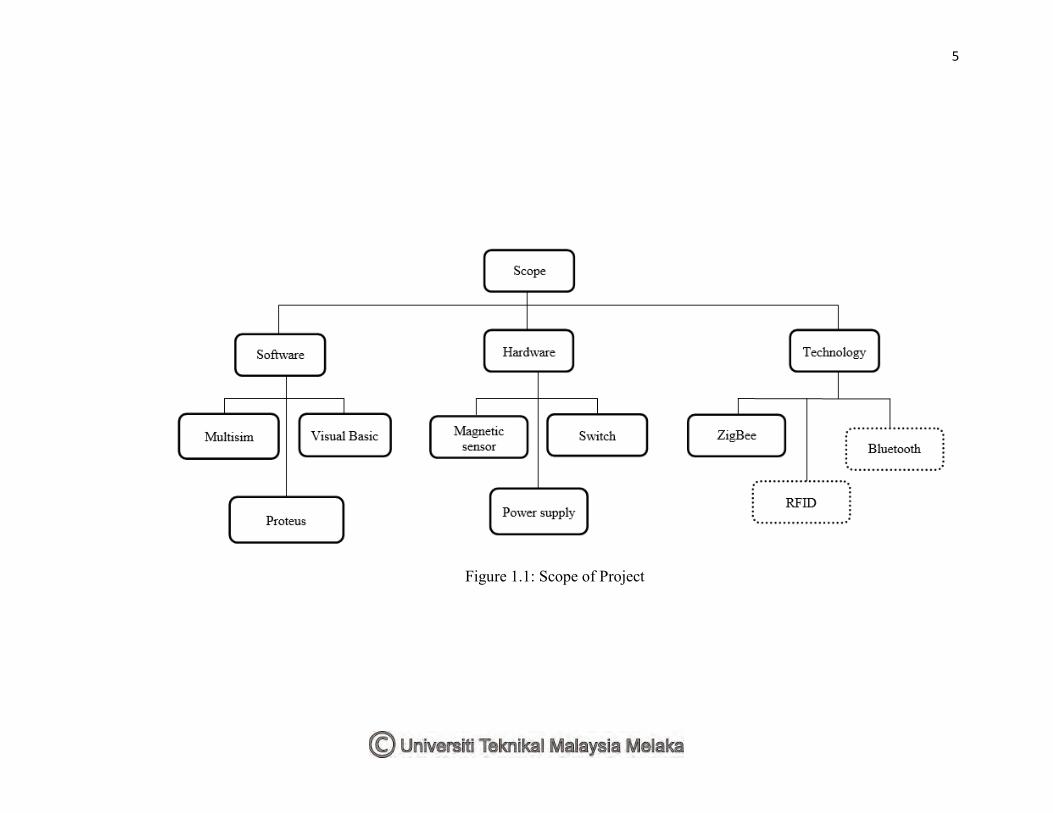
1.5 Scope of Project
The scope of project is shown in Figure 1.1.The scope of this project focused
into three stages, which are hardware, software and technology development. In this
project, it involves two parts in order to accomplish one complete system in wireless
networking. It has two boards collectively from a Zigbee network, one of which is
transmitter and receiver circuit. This project also uses the GSM (Global System for
Mobile Communication) to enable the user or host information when they entered the
home or residence of the robbers.
For the hardware part we will use the magnetic sensor, LCD and buzzer.
Magnetic sensors detect changes and disturbances in a magnetic field like flux, strength
and direction. Door and window sensors come in two pieces. One fits onto the door or
window itself, while its counterpart attaches to the frame. Adhesive usually keeps the
sensors in place, though sensors can be screwed directly into the frame. Position the two
pieces of the sensor right next to each other, because they interact. When the two pieces
are separated, such as when the door or window is opened, they send a signal to the
alarm panel. Liquid crystal display (LCD) is a flat panel display, electronic visual
display, or video display that uses the light modulating properties of liquid crystals. It is
used to display the number of home security hut when ZigBee receiver receives a signal
that the house was broken into by burglars. A buzzer or beeper is an audio signaling
4
device, which may be mechanical, electromechanical, or piezoelectric. It is used to alert
security guard who was in the hut to be aware that there is a housing area home was
entered robbers.
For the software part we will use the Multisim, Proteus and Visual Basic.
Multisim is a circuit simulation based on SPICE (standard for circuit simulation). It
contains a database of components that you can use to build a circuit and many of these
components are simulatable.Proteus is software for microprocessor simulation,
schematic capture, and printed circuit board (PCB) design. Visual Basic was originally
created to make it easier to write programs for the Windows computer operating system.
The basis of Visual Basic is an earlier programming language called BASIC.
5
Figure 1.1: Scope of Project
6
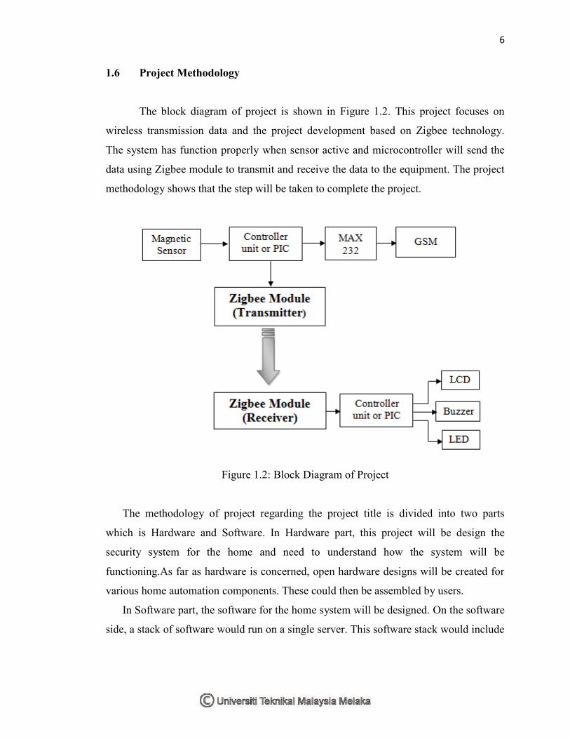
1.6 Project Methodology
The block diagram of project is shown in Figure 1.2. This project focuses on
wireless transmission data and the project development based on Zigbee technology.
The system has function properly when sensor active and microcontroller will send the
data using Zigbee module to transmit and receive the data to the equipment. The project
methodology shows that the step will be taken to complete the project.
Figure 1.2: Block Diagram of Project
The methodology of project regarding the project title is divided into two parts
which is Hardware and Software. In Hardware part, this project will be design the
security system for the home and need to understand how the system will be
functioning.As far as hardware is concerned, open hardware designs will be created for
various home automation components. These could then be assembled by users.
In Software part, the software for the home system will be designed. On the software
side, a stack of software would run on a single server. This software stack would include
7
software for interfacing with devices, software for aggregating, analyzing, and acting
upon these data.
1.7 Project Structure
This report is covered by five chapters. The first chapter starts with overview of
project, objective, problem statement and scope of project. The literature review is
discussed in Chapter 2 and project methodology in Chapter 3. The Chapter 4 covers
hardware and software implementation and the conclusions and suggestions are
respectively covers in Chapter 5. For projects that have been successfully implemented,
there are some places to look into. Here are the main chapters:
Chapter 1: Study about objectives and scope of project.
The purpose of this project is to design and develop a ZigBee wireless system
consisting of a sensor to detect if there is any effect of forced entry into the home.
Chapter 2: Literature review about wireless ZigBee system and sensor.
Research, find and read relevant topics from the sources such as reference books,
internet and journal let’s get deeper knowledge and information for the project.
Research on the system or even less in the market and know what are the
characteristics and capabilities of the product will also provide more information and
understanding in this project.
Chapter 3: Project methodology covers the planning, design and management of
development projects.
This chapter explains more about the project methodology used in this project. This
section will explain more about the way it projects from start to finish. Every single
thing that has been implemented in the project should be described step by step.

8
Chapter 4: Hardware and Software implementation.
The fourth chapter should focus on hardware and software development. In this
chapter also shows the testing process. Testing will be performed on each module in
both hardware and software systems.
Chapter 5: Conclusion and suggestion on the project.
In the final chapter will examine and review the project, whether the solution is done
to achieve the project objectives. Discuss problems, conclusions and
recommendations will be discussed for future improvements in this project.

9
CHAPTER 2
LITERATURE REVIEW
2.0 Chapter Overview
In this chapter will discuss the projects and paper work associated with this
project. Related work was studied to produce the quality and reliability of the project.
By analyzing the projects done before by other researchers, are likely to find out there
are a few features about the projects done. They also recommend some future work that
can be undertaken to improve the project. In addition, there are a few ideas that are used
to implement this project from other projects similar. An extended literature review
process from beginning to end of the project. By review the previous work, the right of
action for the project can be undertaken and the features that must be enhanced to make
this project reliable and marketable. In addition, there are a few findings from the
internet and books used in this project. Along analysis at the beginning of the project,
special features specified in this project and the components used in the project is
determined. In addition it is functional and well understood concept.