zxss10ss1b - donbassmedia.net.ua technical documents... ·...
TRANSCRIPT

ZXSS10 SS1bSoftSwitch Control Equipment
Hardware Description
Version 2.0.1.07
ZTE CORPORATIONNO. 55, Hi-tech Road South, ShenZhen, P.R.ChinaPostcode: 518057Tel: (86) 755 26771900Fax: (86) 755 26770801URL: http://ensupport.zte.com.cnE-mail: [email protected]

LEGAL INFORMATION
Copyright © 2010 ZTE CORPORATION.
The contents of this document are protected by copyright laws and international treaties. Any reproduction or distribution ofthis document or any portion of this document, in any form by any means, without the prior written consent of ZTE CORPO-RATION is prohibited. Additionally, the contents of this document are protected by contractual confidentiality obligations.
All company, brand and product names are trade or service marks, or registered trade or service marks, of ZTE CORPORATIONor of their respective owners.
This document is provided “as is”, and all express, implied, or statutory warranties, representations or conditions are dis-claimed, including without limitation any implied warranty of merchantability, fitness for a particular purpose, title or non-in-fringement. ZTE CORPORATION and its licensors shall not be liable for damages resulting from the use of or reliance on theinformation contained herein.
ZTE CORPORATION or its licensors may have current or pending intellectual property rights or applications covering the subjectmatter of this document. Except as expressly provided in any written license between ZTE CORPORATION and its licensee,the user of this document shall not acquire any license to the subject matter herein.
ZTE CORPORATION reserves the right to upgrade or make technical change to this product without further notice.
Users may visit ZTE technical support website http://ensupport.zte.com.cn to inquire related information.
The ultimate right to interpret this product resides in ZTE CORPORATION.
Revision History
Revision No. Revision Date Revision Reason
R1.0 2010–07-15 First edition
Serial Number: SJ-20100630164932-004
Contents
About This Manual............................................. I
Declaration of RoHS Compliance ....................... I
Cabinet..............................................................1Cabinet ......................................................................... 1
Cabinet Structure ........................................................... 2
Power ........................................................................... 3
Cabinet Parameters ........................................................ 4
Typical Configurations ..................................................... 5
Foreground Shelf.............................................11Shelf Appearance ..........................................................11
Shelf Structure..............................................................12
Board Slot Configuration.................................................14
Shelf Boards .................................................................16
Overview..................................................................16
SC...........................................................................17
ESC .........................................................................20
SSN.........................................................................21
SSNI........................................................................24
SPC .........................................................................25
ESPC .......................................................................28
NIC .........................................................................29
TIC..........................................................................32
CSN.........................................................................33
CSNI........................................................................35
GNIC .......................................................................37
Shelf Power ..................................................................40
SPWBP.....................................................................40
TPOWP.....................................................................41
SPWBF.....................................................................42
SPOWB ....................................................................43
TPOWB ....................................................................44
Confidential and Proprietary Information of ZTE CORPORATION I

ZXSS10 SS1b Hardware Description
Background Database Server ..........................45Overview......................................................................45
SUN Server Background .................................................45
PC Server Background....................................................47
Figures ............................................................53
Tables .............................................................55
Glossary ..........................................................57
II Confidential and Proprietary Information of ZTE CORPORATION
About This Manual
Purpose At first, thank you for choosing ZXSS10 SS1b of ZTE Corporation!
ZXSS10 SS1b is fully compatible with the layered standard NGNmodel. It can provide NGN with service call and connection con-trol functions which are required by real-time services. By usingZXSS10 SS1b, operators can provide users with many kinds ofmultimedia services which involve voice, video and data. ZXSS10SS1b is, therefore, the core of NGN in terms of call and control.
This manual describes the working principle, functions, charac-teristics, applications, related interfaces and protocols of ZXSS10SS1b.
IntendedAudience
This manual is intended for
� Technical managers
� Network planning engineers
� Equipment installation engineers
� Maintenance engineers
Prerequisite Skilland Knowledge
To use this document effectively, users should have a general un-derstanding of SoftSwitch system.
What Is in ThisManual
This manual contains the following chapters:
Chapter Summary
Chapter 1, Cabinet It introduces the cabinet of ZXSS10SS1b
Chapter 2, Foreground Shelf It introduces the shelf, boards andshelf power of ZXSS10 SS1b
Chapter 3, Background DatabaseServer
It introduces the backgrounddatabase server used by ZXSS10SS1b, which includes SUN serverand PC server
Conventions ZTE documents employ the following typographical conventions.
Typeface Meaning
Italics References to other Manuals and documents.
“Quotes” Links on screens.
Bold Menus, menu options, function names, input fields,radio button names, check boxes, drop-down lists,dialog box names, window names.
CAPS Keys on the keyboard and buttons on screens andcompany name.
Confidential and Proprietary Information of ZTE CORPORATION I

ZXSS10 SS1b Hardware Description
Typeface Meaning
Note: Provides additional information about a certaintopic.
Checkpoint: Indicates that a particular step needs tobe checked before proceeding further.
Tip: Indicates a suggestion or hint to make thingseasier or more productive for the reader.
Mouse operation conventions are listed as follows:
Typeface Meaning
Click Refers to clicking the primary mouse button (usually theleft mouse button) once.
Double-click
Refers to quickly clicking the primary mouse button(usually the left mouse button) twice.
Right-click Refers to clicking the secondary mouse button (usuallythe right mouse button) once.
II Confidential and Proprietary Information of ZTE CORPORATION

Declaration of RoHSCompliance
To minimize the environmental impact and take more responsibil-ity to the earth we live, this document shall serve as formal dec-laration that ZXSS10 SS1b manufactured by ZTE CORPORATIONare in compliance with the Directive 2002/95/EC of the EuropeanParliament - RoHS (Restriction of Hazardous Substances) with re-spect to the following substances:
� Lead (Pb)
� Mercury (Hg)
� Cadmium (Cd)
� Hexavalent Chromium (Cr (VI))
� PolyBrominated Biphenyls (PBB’s)
� PolyBrominated Diphenyl Ethers (PBDE’s)
…
The ZXSS10 SS1b manufactured by ZTE CORPORATION meetthe requirements of EU 2002/95/EC; however, some assembliesare customized to client specifications. Addition of specialized,customer-specified materials or processes which do not meet therequirements of EU 2002/95/EC may negate RoHS compliance of theassembly. To guarantee compliance of the assembly, the need forcompliant product must be communicated to ZTE CORPORATION inwritten form. This declaration is issued based on our current levelof knowledge. Since conditions of use are outside our control, ZTECORPORATION makes no warranties, express or implied, and assumesno liability in connection with the use of this information.
Confidential and Proprietary Information of ZTE CORPORATION I

ZXSS10 SS1b Hardware Description
This page is intentionally blank.
II Confidential and Proprietary Information of ZTE CORPORATION

C h a p t e r 1
Cabinet
Table of ContentsCabinet ............................................................................. 1Cabinet Structure ............................................................... 2Power ............................................................................... 3Cabinet Parameters ............................................................ 4Typical Configurations ......................................................... 5
CabinetFigure 1 shows the cabinet used by ZXSS10 SS1b.
FIGURE 1 ZXSS10 SS1B CABINET
Confidential and Proprietary Information of ZTE CORPORATION 1

ZXSS10 SS1b Hardware Description
Cabinet StructureZXSS10 SS1b uses B6080-20A, one of the standard 19-inch cab-inets, or B6080-20B, one of the 19-inch simplified cabinets as itscabinet.
Caution:
The doors on the right side and left side of Cabinet B6080-20Aare not dismountable; While doors of cabinet B6080-20B are dis-mountable.
Cabinet B6080-20A consists of a rack, front and rear doors, sidepanels, a top side panel, decorative panels, a top fan module, adust filter and bottom supports. Figure 2 shows the cabinet struc-ture.
FIGURE 2 CABINET STRUCTURE
1. Back Door2. Anti-Rat Pocket
3. Top Side Panel4. Side Door
2 Confidential and Proprietary Information of ZTE CORPORATION
Chapter 1 Cabinet
5. Top Fan Module6. Top Front Panel7. Front Door8. Chassis
9. Front Decorative Panel10. Dust Filter11. Bottom Support12. Side Decorative Panel
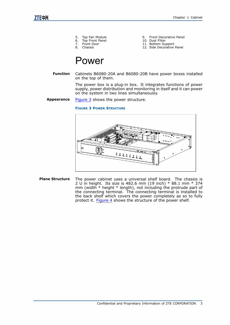
PowerFunction Cabinets B6080-20A and B6080-20B have power boxes installed
on the top of them.
The power box is a plug-in box. It integrates functions of powersupply, power distribution and monitoring in itself and it can poweron the system in two lines simultaneously.
Appearance Figure 3 shows the power structure.
FIGURE 3 POWER STRUCTURE
Plane Structure The power cabinet uses a universal shelf board. The chassis is2 U in height. Its size is 482.6 mm (19 inch) * 88.1 mm * 374mm (width * height * length), not including the protrude part ofthe connecting terminal. The connecting terminal is installed tothe back shelf which covers the power completely as so to fullyprotect it. Figure 4 shows the structure of the power shelf.
Confidential and Proprietary Information of ZTE CORPORATION 3
ZXSS10 SS1b Hardware Description
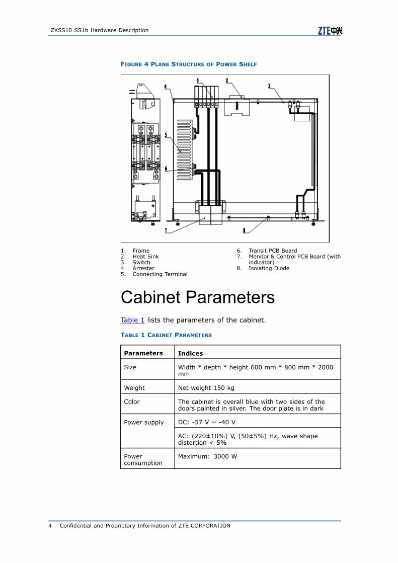
FIGURE 4 PLANE STRUCTURE OF POWER SHELF
1. Frame2. Heat Sink3. Switch4. Arrester5. Connecting Terminal
6. Transit PCB Board7. Monitor & Control PCB Board (with
indicator)8. Isolating Diode
Cabinet ParametersTable 1 lists the parameters of the cabinet.
TABLE 1 CABINET PARAMETERS
Parameters Indices
Size Width * depth * height 600 mm * 800 mm * 2000mm
Weight Net weight 150 kg
Color The cabinet is overall blue with two sides of thedoors painted in silver. The door plate is in dark
DC: -57 V ~ -40 VPower supply
AC: (220±10%) V, (50±5%) Hz, wave shapedistortion < 5%
Powerconsumption
Maximum: 3000 W
4 Confidential and Proprietary Information of ZTE CORPORATION
Chapter 1 Cabinet
Typical ConfigurationsZXSS10 SS1b can choose different cabinet configurations flexiblyaccording to different traffic models. The following shows sometypical cabinet configurations.
Note:
The configurations chose by offices can differ from the ones intro-duced in this section.
� Figure 5 shows the configuration of ZXSS10 SS1b rack S. Thisconfiguration is appropriate in a condition which needs to pro-vide a small amount of users with processing capacity. A singleshelf configuration is enough in this condition.
Confidential and Proprietary Information of ZTE CORPORATION 5

ZXSS10 SS1b Hardware Description
FIGURE 5 TYPICAL CONFIGURATION OF ZXSS10 SS1B RACK S
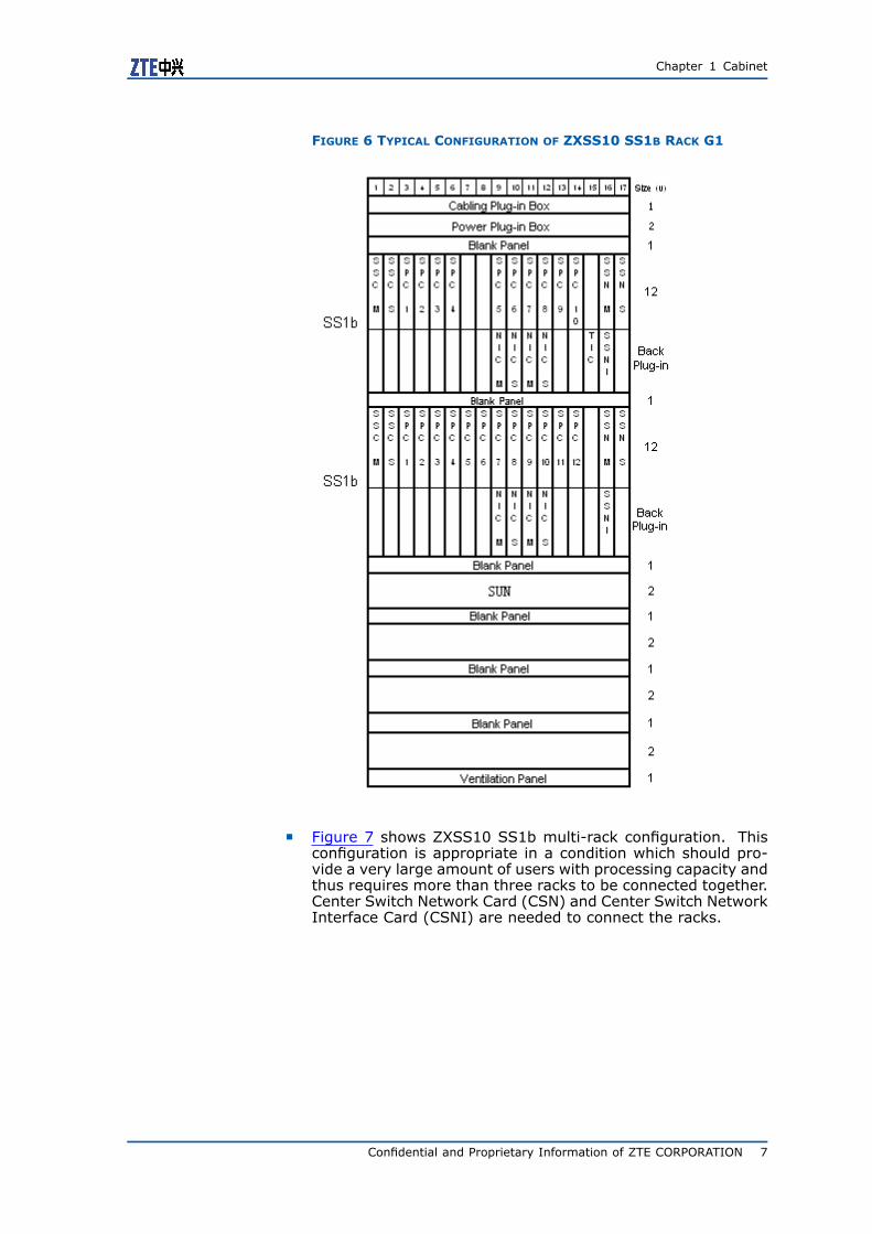
� Figure 6 shows the configuration of ZXSS10 SS1b rack G1. Thisconfiguration is appropriate in a condition which should providemore than hundreds of thousands of users with processing ca-pacity. So it needs two or three shelves to be connected to-gether. SSNI is needed to connect the shelves.
6 Confidential and Proprietary Information of ZTE CORPORATION
Chapter 1 Cabinet
FIGURE 6 TYPICAL CONFIGURATION OF ZXSS10 SS1B RACK G1
� Figure 7 shows ZXSS10 SS1b multi-rack configuration. Thisconfiguration is appropriate in a condition which should pro-vide a very large amount of users with processing capacity andthus requires more than three racks to be connected together.Center Switch Network Card (CSN) and Center Switch NetworkInterface Card (CSNI) are needed to connect the racks.
Confidential and Proprietary Information of ZTE CORPORATION 7

ZXSS10 SS1b Hardware Description
FIGURE 7 TYPICAL CONFIGURATION OF ZXSS10 SS1B MULTI-RACK
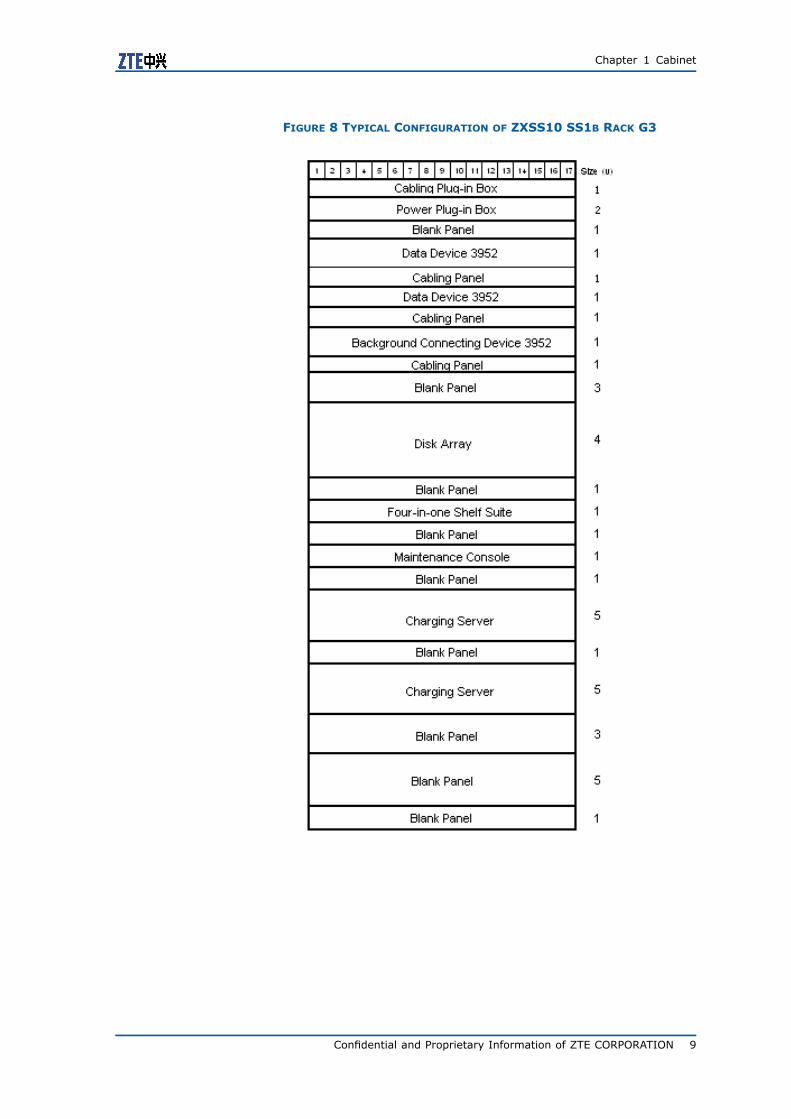
� Figure 8 shows the typical configuration of ZXSS10 SS1b rackG3.
8 Confidential and Proprietary Information of ZTE CORPORATION
Chapter 1 Cabinet
FIGURE 8 TYPICAL CONFIGURATION OF ZXSS10 SS1B RACK G3
Confidential and Proprietary Information of ZTE CORPORATION 9

ZXSS10 SS1b Hardware Description
This page is intentionally blank.
10 Confidential and Proprietary Information of ZTE CORPORATION
C h a p t e r 2
Foreground Shelf
Table of ContentsShelf Appearance ..............................................................11Shelf Structure..................................................................12Board Slot Configuration.....................................................14Shelf Boards .....................................................................16Shelf Power ......................................................................40
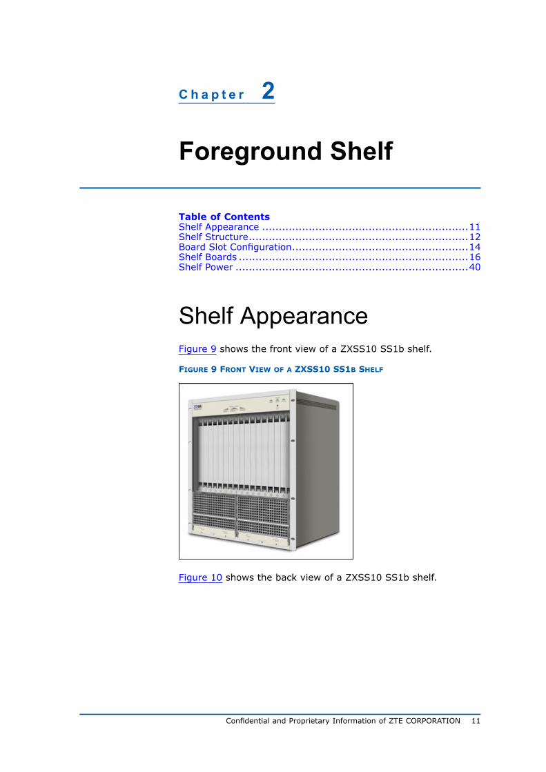
Shelf AppearanceFigure 9 shows the front view of a ZXSS10 SS1b shelf.
FIGURE 9 FRONT VIEW OF A ZXSS10 SS1B SHELF
Figure 10 shows the back view of a ZXSS10 SS1b shelf.
Confidential and Proprietary Information of ZTE CORPORATION 11

ZXSS10 SS1b Hardware Description
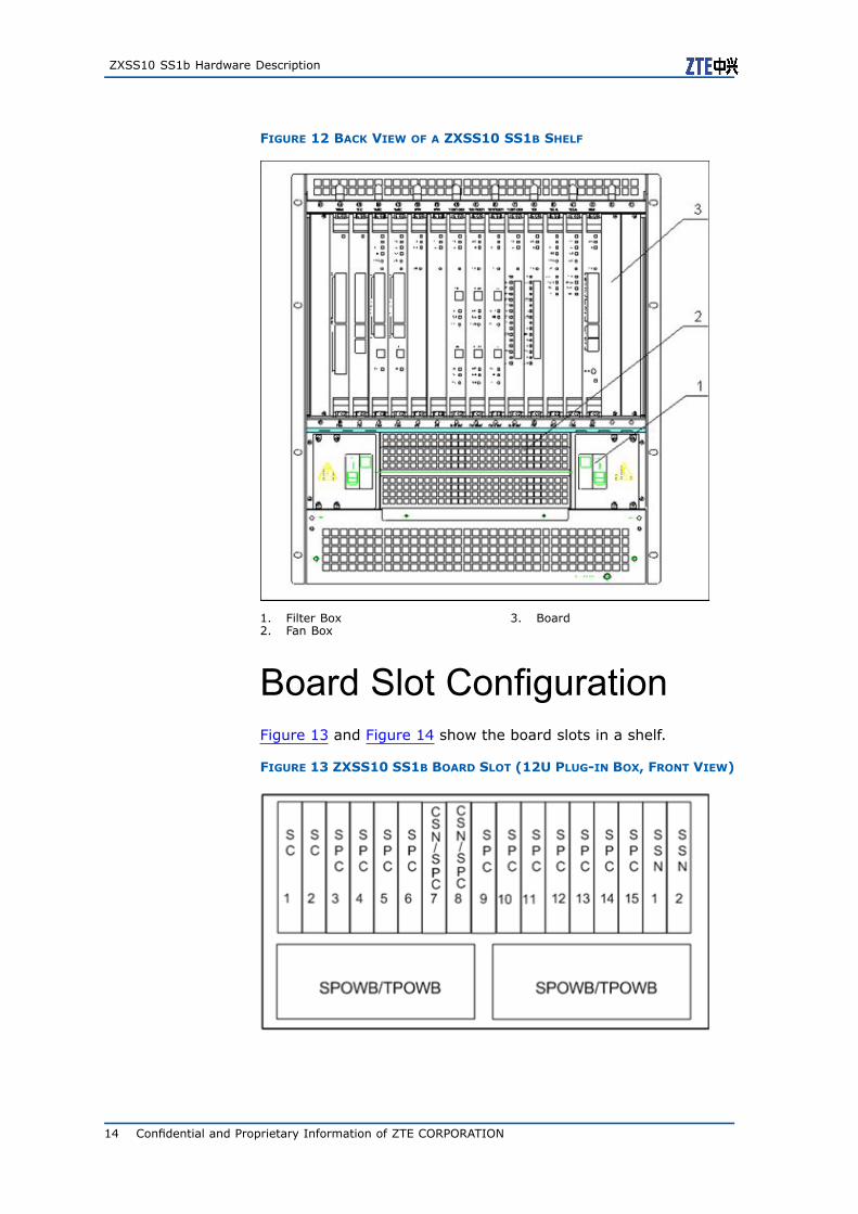
FIGURE 10 BACK VIEW OF A ZXSS10 SS1B SHELF
Shelf StructureZXSS10 SS1b uses a standard 19 plug-in box which is 12 U inheight. Figure 11 and Figure 12 show the structure of the shelf.The backplane is positioned in the middle. ZXSS10 SS1b provides17 board slots. The boards are classified into front plug-in boardsand back plug-in boards. A SPOWB power box is installed on thefront side; A SPWBP power distributor box and a SPWBF fan plug-inbox are installed on the back side.
12 Confidential and Proprietary Information of ZTE CORPORATION

Chapter 2 Foreground Shelf
FIGURE 11 FRONT VIEW OF A ZXSS10 SS1B SHELF
1. Power Box SPOWB/TPOWB2. Board
Confidential and Proprietary Information of ZTE CORPORATION 13
ZXSS10 SS1b Hardware Description
FIGURE 12 BACK VIEW OF A ZXSS10 SS1B SHELF
1. Filter Box2. Fan Box
3. Board
Board Slot ConfigurationFigure 13 and Figure 14 show the board slots in a shelf.
FIGURE 13 ZXSS10 SS1B BOARD SLOT (12U PLUG-IN BOX, FRONT VIEW)
14 Confidential and Proprietary Information of ZTE CORPORATION
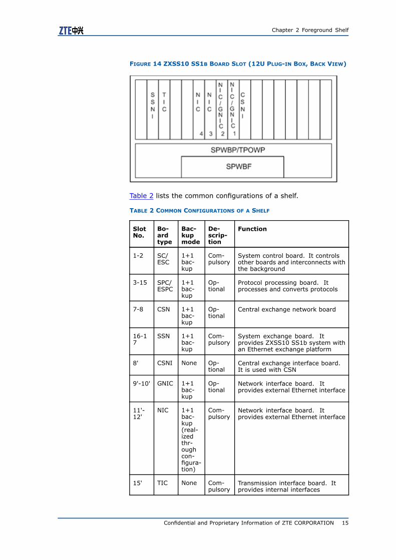
Chapter 2 Foreground Shelf
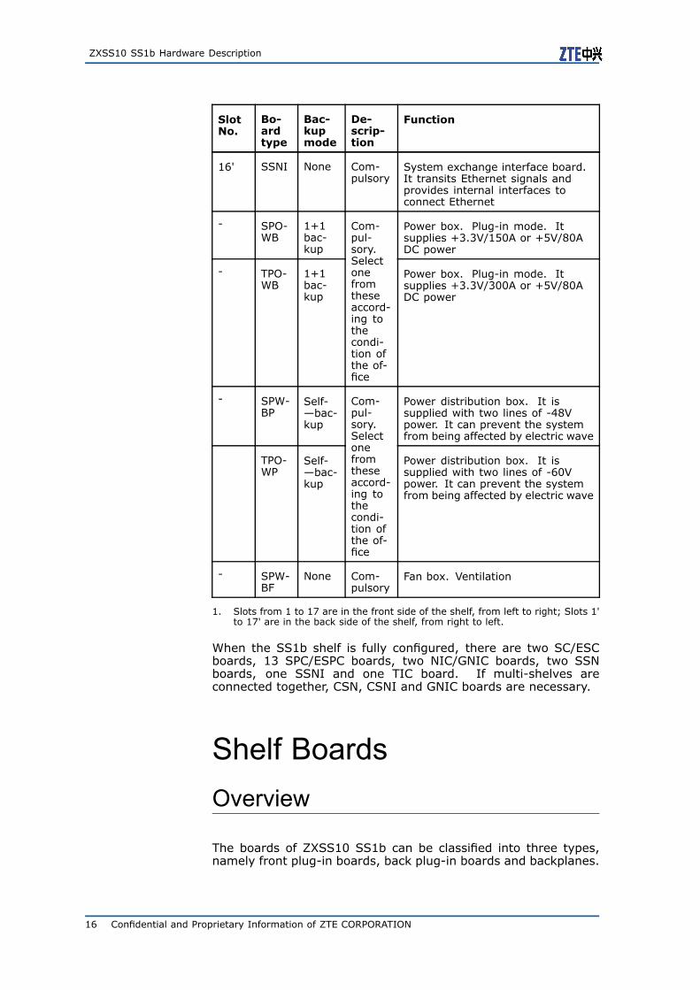
FIGURE 14 ZXSS10 SS1B BOARD SLOT (12U PLUG-IN BOX, BACK VIEW)
Table 2 lists the common configurations of a shelf.
TABLE 2 COMMON CONFIGURATIONS OF A SHELF
SlotNo.
Bo-ardtype
Bac-kupmode
De-scrip-tion
Function
1-2 SC/ESC
1+1bac-kup
Com-pulsory
System control board. It controlsother boards and interconnects withthe background
3-15 SPC/ESPC
1+1bac-kup
Op-tional
Protocol processing board. Itprocesses and converts protocols
7-8 CSN 1+1bac-kup
Op-tional
Central exchange network board
16-17
SSN 1+1bac-kup
Com-pulsory
System exchange board. Itprovides ZXSS10 SS1b system withan Ethernet exchange platform
8' CSNI None Op-tional
Central exchange interface board.It is used with CSN
9'-10' GNIC 1+1bac-kup
Op-tional
Network interface board. Itprovides external Ethernet interface
11'-12'
NIC 1+1bac-kup(real-izedthr-oughcon-figura-tion)
Com-pulsory
Network interface board. Itprovides external Ethernet interface
15' TIC None Com-pulsory
Transmission interface board. Itprovides internal interfaces
Confidential and Proprietary Information of ZTE CORPORATION 15
ZXSS10 SS1b Hardware Description
SlotNo.
Bo-ardtype
Bac-kupmode
De-scrip-tion
Function
16' SSNI None Com-pulsory
System exchange interface board.It transits Ethernet signals andprovides internal interfaces toconnect Ethernet
- SPO-WB
1+1bac-kup
Power box. Plug-in mode. Itsupplies +3.3V/150A or +5V/80ADC power
- TPO-WB
1+1bac-kup
Com-pul-sory.Selectonefromtheseaccord-ing tothecondi-tion ofthe of-fice
Power box. Plug-in mode. Itsupplies +3.3V/300A or +5V/80ADC power
- SPW-BP
Self-—bac-kup
Power distribution box. It issupplied with two lines of -48Vpower. It can prevent the systemfrom being affected by electric wave
TPO-WP
Self-—bac-kup
Com-pul-sory.Selectonefromtheseaccord-ing tothecondi-tion ofthe of-fice
Power distribution box. It issupplied with two lines of -60Vpower. It can prevent the systemfrom being affected by electric wave
- SPW-BF
None Com-pulsory
Fan box. Ventilation
1. Slots from 1 to 17 are in the front side of the shelf, from left to right; Slots 1'to 17' are in the back side of the shelf, from right to left.
When the SS1b shelf is fully configured, there are two SC/ESCboards, 13 SPC/ESPC boards, two NIC/GNIC boards, two SSNboards, one SSNI and one TIC board. If multi-shelves areconnected together, CSN, CSNI and GNIC boards are necessary.
Shelf BoardsOverview
The boards of ZXSS10 SS1b can be classified into three types,namely front plug-in boards, back plug-in boards and backplanes.
16 Confidential and Proprietary Information of ZTE CORPORATION

Chapter 2 Foreground Shelf
� Front plug-in boards: They mainly refer to those control &management boards and service protocol processing boards.
� Back plug-in boards: They mainly refer to the interface boards.
� Backplanes: They, positioned between the front plug-in boardsand the back plug-in boards, mainly provide a function thatmakes the signal interconnection between boards possible.
Table 3 shows the boards contained in ZXSS10 SS1b.
TABLE 3 ZXSS10 SS1B BOARDS
Board Position Whether used in pair
SC Front plug-in board No
ESC Front plug-in board No
SPC Front plug-in board No
ESPC Front plug-in board No
NIC Back plug-in board No
GNIC Back plug-in board No
TIC Back plug-in board No
CSN Front plug-in board
CSNI Back plug-in board
Yes
SSN Front plug-in board
SSNI Back plug-in board
Yes
SC
Functions Two front plug-in SC boards can be installed in slots 1 and 2, form-ing a pair of active and standby boards . Its reliability is as highas 99.999% in terms of the active/standby switching and redun-dancy of the hardware structure and software support. It mainlyprovides the following functions.
1. Powerful processing performance, memory with large size andpart of protocol processing.
2. External interfaces, for example, hard disk interface, serialports, and one background database interface.
3. Controlling and monitoring the working state of other boardsin the system, and providing hot-swapping function.
4. Provides communication interfaces (two 100MBase-Ts) be-tween itself and System Switching Network Card (SSN).
5. Provides signals for active/standby control and communicationto enable the active/standby switchover between SC.
6. Provides power monitoring interfaces and state signals.
Confidential and Proprietary Information of ZTE CORPORATION 17
ZXSS10 SS1b Hardware Description
7. Provides board position signals and shelf ID signals.
Front Panel Figure 15 shows the front panel of SC.
FIGURE 15 SC PANEL
There are black plastic extractors at both sides of the front panel.Indicators for active/standby SCs are in the middle. At the rightside of them are a button for active/standby switchover, an RJ45socket, a running indicator, a fault indicator, a reset button, anRJ11 serial port and a hot-swapping indicator.
Indicators Table 4 lists the indicators on SC front panel.
TABLE 4 INDICATORS ON THE SC PANEL
Name Indicator Description
MST Greenindicator
Indicates the status of the board. If it lights,this SC works as an active board
RES Greenindicator
Indicates the status of the board. If it lights,this SC works as a standby board
RUN Greenindicator
Indicates the running status of the board.It flashes at 1 Hz/second. When Itflashes rapidly, it means that the board isdownloading a version. If the SC standbyboard works normally, the indicator flashesat 2 Hz/second
FAU Red indicator It indicates faults. If it lights, somethingwrong must occur to the board
Buttons Table 5 lists the functions of the two buttons on the SC front panel.
TABLE 5 BUTTONS ON THE SC PANEL
Name Description
RST Reset the SC manually
EXCH Perform active-standby SC switchover manually
Interfaces Table 6 lists the interfaces on the SC front panel.
TABLE 6 INTERFACES ON THE SC PANEL
Name Type Description
10/100BA-SE-T
RJ45 10/100 M Ethernet port used fordebugging
RS232 RJ11 RS232 interface used for debugging
18 Confidential and Proprietary Information of ZTE CORPORATION
Chapter 2 Foreground Shelf
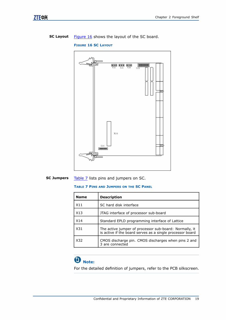
SC Layout Figure 16 shows the layout of the SC board.
FIGURE 16 SC LAYOUT
SC Jumpers Table 7 lists pins and jumpers on SC.
TABLE 7 PINS AND JUMPERS ON THE SC PANEL
Name Description
X11 SC hard disk interface
X13 JTAG interface of processor sub-board
X14 Standard EPLD programming interface of Lattice
X31 The active jumper of processor sub-board: Normally, itis active if the board serves as a single processor board
X32 CMOS discharge pin. CMOS discharges when pins 2 and3 are connected
Note:
For the detailed definition of jumpers, refer to the PCB silkscreen.
Confidential and Proprietary Information of ZTE CORPORATION 19
ZXSS10 SS1b Hardware Description
ESC
Functions As an enhanced version of SC, Enhanced SC (ESC) is designed toimprove the overall processing capability of ZXSS10 SS1b.
ESC has the following functions.
� Has powerful processing capability and large-size memory; Itshares part of protocol processing tasks.
� Provides external interfaces that are necessary for the system,such as hard disk interfaces and UART serial ports.
� Monitors and controls the working status of other boards withinthe system; Provides a hot plugging function.
� Provides ports for communication with two SSNs.
� Provides active/standby control and communication signals;Provides an active/standby function and auxiliary communi-cation function.
� Provides interfaces and status signals relating to power detec-tion, and provides information about slot numbers and shelfnumbers.
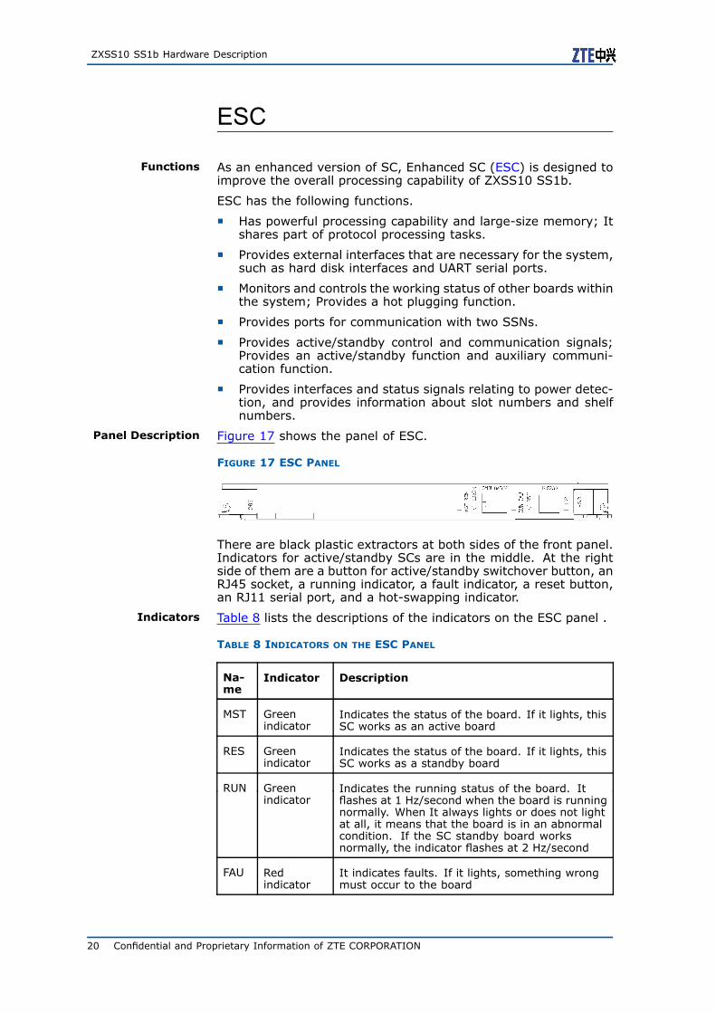
Panel Description Figure 17 shows the panel of ESC.
FIGURE 17 ESC PANEL
There are black plastic extractors at both sides of the front panel.Indicators for active/standby SCs are in the middle. At the rightside of them are a button for active/standby switchover button, anRJ45 socket, a running indicator, a fault indicator, a reset button,an RJ11 serial port, and a hot-swapping indicator.
Indicators Table 8 lists the descriptions of the indicators on the ESC panel .
TABLE 8 INDICATORS ON THE ESC PANEL
Na-me
Indicator Description
MST Greenindicator
Indicates the status of the board. If it lights, thisSC works as an active board
RES Greenindicator
Indicates the status of the board. If it lights, thisSC works as a standby board
RUN Greenindicator
Indicates the running status of the board. Itflashes at 1 Hz/second when the board is runningnormally. When It always lights or does not lightat all, it means that the board is in an abnormalcondition. If the SC standby board worksnormally, the indicator flashes at 2 Hz/second
FAU Redindicator
It indicates faults. If it lights, something wrongmust occur to the board
20 Confidential and Proprietary Information of ZTE CORPORATION

Chapter 2 Foreground Shelf
Buttons Table 9 lists the descriptions of the two buttons on the ESC panel
TABLE 9 BUTTONS ON THE ESC PANEL
Name Description
RST Reset the SC manually
EXCH Perform active-standby SC changeover manually
Interfaces Table 10 lists the descriptions of the interfaces on the ESC Panel.
TABLE 10 INTERFACES ON THE ESC PANEL
Name Type Description
10/100BA-SE-T
RJ45 10/100 M Ethernet port used fordebugging
RS232 RJ11 RS232 interface used for debugging
SC Jumpers Table 11 lists the descriptions of pins and jumpers within the ESC.
TABLE 11 PINS AND JUMPERS ON THE ESC PANEL
Name Description
X7 The FE port for debugging use, that is, RJ45 connectorwith a LED
X8 The RS232 serial port for debugging use, that is, thestandard RJ11 connector
X9, X10 DDRII DIMM240 socket
X11 SATA disk interface socket
X13 3V li-Ion battery 2032 socket
X14 For the boot way, select pin.
� The normal boot way is selected if pin 1 and pin 2are connected
� The online-downloading boot way is selected if pin 2and pin 3 are connected
SSN
Note:
SSN has five types of physical boards, namely SSNA, SSNB, SSNC,SSN/4 and SSNB/2. SSNB/2 is used currently.
Confidential and Proprietary Information of ZTE CORPORATION 21
ZXSS10 SS1b Hardware Description
Functions In the SS1b hardware platform, the exchange part of Ethernetconsists of two boards, namely
� SSN, which realizes the Ethernet exchange function;
� SSNI, which realizes 100 M and 1 G Ethernet interface backup.
Two SSN front plug-in boards can be installed in slots 16 and 17,forming a pair of active/standby boards. Their main functionscover:
1. Provide a set of Ethernet switching mechanism.
2. Provide 24 100 Mbit/s Ethernet ports, in which:
� Fifteen 100 Mbit/s Ethernet ports serve as the communica-tion bus between 13 front SPCs and two SC boards.
� Four 100 Mbit/s Ethernet ports serve as the communica-tion bus of four NIC, implementing system monitoring andexchanging monitoring and alarm information.
� Five 100 Mbit/s Ethernet ports serve as the communicationchannel for cross-shelf or cross-shelf expansion.
� Two 1000 Mbit/s Ethernet ports are reserved as externalnetwork interfaces. The transmission distance of a 1000M Ethernet port can reach 100 m by using the Category 5copper wire technology.
3. Provide an RS485 bus which is used as an auxiliary communi-cation channel used by SC to control SSN.
4. Provides board position signals and shelf ID signals.
Panel Description Figure 18 shows the panel of SSN
FIGURE 18 SSN PANEL
Indicators Table 12 lists the descriptions of SSN indicators.
TABLE 12 INDICATORS ON THE SSN PANEL
Name Indicator Description
RUN Greenindicator
It indicates the running status. Whenit flashes at 1 Hz/second, the board isworking normally. When it always lights ordoes not light at all, something wrong mustoccur to the board
FAU Red indicator It indicates faults. It will not light untilsomething wrong occurs to the board
MST GreenIndicator
When the board is used as an active board,it lights; When the board is used as astandby board, it does not light
RES GreenIndicator
When the board is used as a standby board,it lights; When the board is used as anactive board, it does not light
22 Confidential and Proprietary Information of ZTE CORPORATION

Chapter 2 Foreground Shelf
Buttons Table 13 lists the descriptions of SSN buttons.
TABLE 13 BUTTONS ON THE SSN PANEL
Name Description
RST Reset the SC manually
EXCH Perform manual SSN switchover
Interfaces Table 14 lists the interface descriptions of SSN
TABLE 14 INTERFACES ON THE SSN PANEL
Name Type Description
10/100BA-SE-T
RJ45 10/100 M Ethernet port used for debugging
RS232 RJ11 RS232 interface used for debugging
SC Layout Figure 19 shows the layout of SSN.
FIGURE 19 SSN LAYOUT
SC Jumpers Table 15 lists the descriptions of SSN jumpers and pins.
Confidential and Proprietary Information of ZTE CORPORATION 23

ZXSS10 SS1b Hardware Description
TABLE 15 JUMPERS AND PINS ON THE SSN PANEL
Name Description
X9 EPLD (LATICE) online programming JTAG port
X10 CPU JTAG port, PowerTAP emulation socket
SSNI
Functions SSNI is a back plug-in board. It can be installed in slot 33. SSNIconsists of a 100 M network interface transformer and a high fre-quency relay.
SSNI accomplishes the following functions.
� Provide a 100 M Ethernet port and active/standby 1 G Ethernetinterfaces.
� Implement connection between SSN, SC, SPC and NIC.
� Provide five 100 M and two 1 G Ethernet exporters.
� Provide the other boards in the shelf with shelf numbers.
Panel Description Figure 20 shows the SSNI panel.
FIGURE 20 SSNI PANEL
Indicator Table 16 lists the descriptions of SSNI indicator.
TABLE 16 INDICATOR ON THE SSNI PANEL
Name Indicator Description
PWR GreenIndicator
It indicates the power status. When theboard is running normally, this indicatorlights; When something wrong occurs to theboard, it does not light
Interfaces Table 17 lists the interfaces on the SSNI panel.
TABLE 17 INTERFACES ON THE SSNI PANEL
Name Type Description
10/100BASE-T1-5
RJ45 Five 10/100Bast-T Ethernet ports forcross-shelf expansion
1000BASE-T1-2
RJ45 Two external network ports
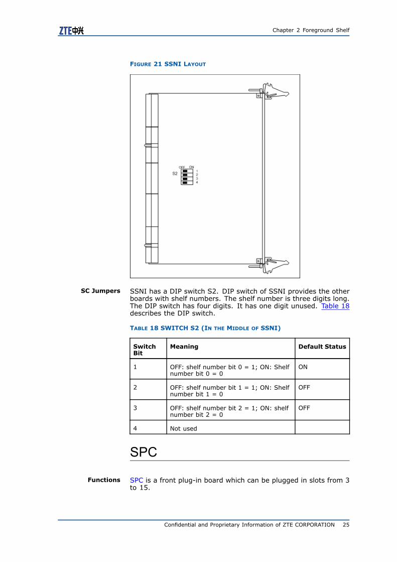
SC Layout Figure 21 shows the layout of SSNI.
24 Confidential and Proprietary Information of ZTE CORPORATION
Chapter 2 Foreground Shelf
FIGURE 21 SSNI LAYOUT
SC Jumpers SSNI has a DIP switch S2. DIP switch of SSNI provides the otherboards with shelf numbers. The shelf number is three digits long.The DIP switch has four digits. It has one digit unused. Table 18describes the DIP switch.
TABLE 18 SWITCH S2 (IN THE MIDDLE OF SSNI)
SwitchBit
Meaning Default Status
1 OFF: shelf number bit 0 = 1; ON: Shelfnumber bit 0 = 0
ON
2 OFF: shelf number bit 1 = 1; ON: Shelfnumber bit 1 = 0
OFF
3 OFF: shelf number bit 2 = 1; ON: shelfnumber bit 2 = 0
OFF
4 Not used
SPC
Functions SPC is a front plug-in board which can be plugged in slots from 3to 15.
Confidential and Proprietary Information of ZTE CORPORATION 25
ZXSS10 SS1b Hardware Description
SPC processes and translates various protocols and reports main-tenance information to SC or receives control information from SC.As a main unit of protocol processing in ZXSS10 SS1b, SPC accom-plishes the following functions:
� Provide powerful processing capability and large-size memoryto process SoftSwitch-related protocols.
� Provide a set of 100 M Ethernet ports for communication withother boards in system and data forwarding.
� Provide hot-swap function and software/hardware interfaces toimplement HA with SC.
� Provide a set of RS485 communication bus as another interfacefor communicating with SC.
� Provide board position signals and shelf ID information.
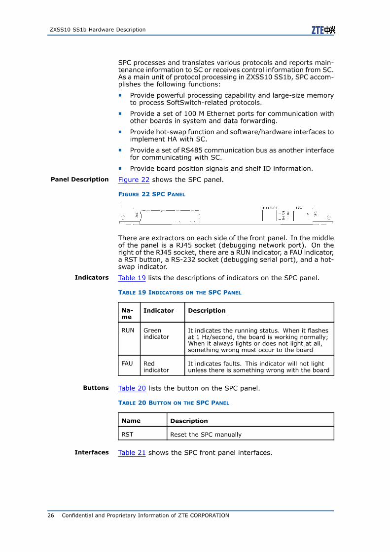
Panel Description Figure 22 shows the SPC panel.
FIGURE 22 SPC PANEL
There are extractors on each side of the front panel. In the middleof the panel is a RJ45 socket (debugging network port). On theright of the RJ45 socket, there are a RUN indicator, a FAU indicator,a RST button, a RS-232 socket (debugging serial port), and a hot-swap indicator.
Indicators Table 19 lists the descriptions of indicators on the SPC panel.
TABLE 19 INDICATORS ON THE SPC PANEL
Na-me
Indicator Description
RUN Greenindicator
It indicates the running status. When it flashesat 1 Hz/second, the board is working normally;When it always lights or does not light at all,something wrong must occur to the board
FAU Redindicator
It indicates faults. This indicator will not lightunless there is something wrong with the board
Buttons Table 20 lists the button on the SPC panel.
TABLE 20 BUTTON ON THE SPC PANEL
Name Description
RST Reset the SPC manually
Interfaces Table 21 shows the SPC front panel interfaces.
26 Confidential and Proprietary Information of ZTE CORPORATION
Chapter 2 Foreground Shelf
TABLE 21 INTERFACES ON THE SPC PANEL
Name Type Description
10/100BA-SE-T
RJ45 10/100 M Ethernet port used for debugging
RS232 RJ11 RS232 interface used for debugging
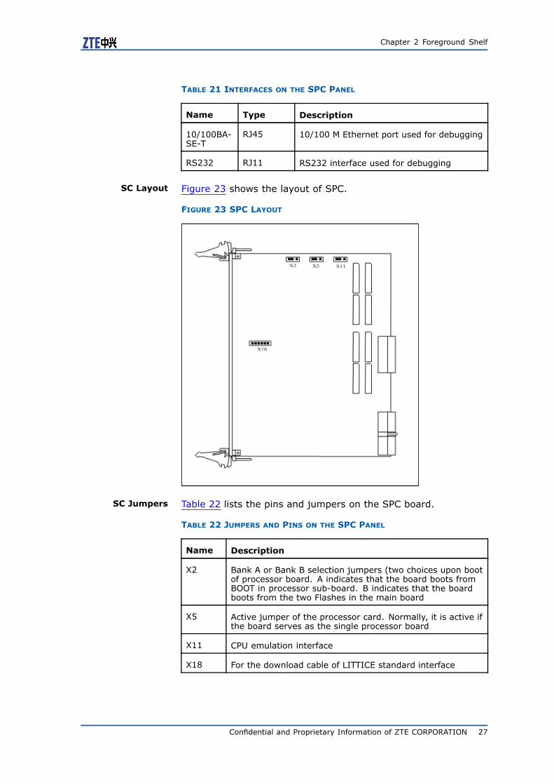
SC Layout Figure 23 shows the layout of SPC.
FIGURE 23 SPC LAYOUT
SC Jumpers Table 22 lists the pins and jumpers on the SPC board.
TABLE 22 JUMPERS AND PINS ON THE SPC PANEL
Name Description
X2 Bank A or Bank B selection jumpers (two choices upon bootof processor board. A indicates that the board boots fromBOOT in processor sub-board. B indicates that the boardboots from the two Flashes in the main board
X5 Active jumper of the processor card. Normally, it is active ifthe board serves as the single processor board
X11 CPU emulation interface
X18 For the download cable of LITTICE standard interface
Confidential and Proprietary Information of ZTE CORPORATION 27

ZXSS10 SS1b Hardware Description
Note:
For the detailed definition of jumpers, refer to the PCB silkscreen.
ESPC
Functions As an enhanced version of SPC, Enhanced SPC (ESPC) is designedto improve the overall processing performance of ZXSS10 SS1b.
ESPC has the following functions.
� Has powerful processing performance and large-size memory;Shares part of protocol processing tasks.
� Provides ports for communication with other boards.
� Provides SC-controlled auxiliary communication channels.
Panel Description Figure 24 shows the ESPC panel.
FIGURE 24 ESPC PANEL
There are extractors on each side of front panel. In the middle ofthe panel is a RJ45 socket (debugging network port). On the rightof the RJ45 socket, there are a RUN indicator, a FAU indicator, aRST button, a RS-232 socket (debugging serial port), and a hot-swap indicator.
Indicators Table 23 lists the descriptions of indicators on the ESPC panel.
TABLE 23 INDICATORS ON THE ESPC PANEL
Na-me
Indicator Description
RUN Greenindicator
It indicates the running status. When it flashesat 1 Hz/second, the board is working normally;When it always lights or does not light at all,something wrong must occur to the board
FAU Red indicator It indicates faults. This indicator will not lightunless there is something wrong with the board
Buttons Table 24 lists the panel button.
TABLE 24 BUTTON ON THE ESPC PANEL
Name Description
RST Reset the SPC manually.
28 Confidential and Proprietary Information of ZTE CORPORATION
Chapter 2 Foreground Shelf
Interfaces Table 25 lists interfaces on the panel of the ESPC.
TABLE 25 INTERFACES ON THE ESPC PANEL
Name Type Description
10/100BA-SE-T
RJ45 10/100 M Ethernet port used fordebugging
RS232 RJ11 RS232 interface used for debugging
SC Jumpers Table 26 lists the descriptions of jumpers on the ESPC.
TABLE 26 PINS AND JUMPERS ON THE ESPC PANEL
Name Description
X7 The FE port for debugging use, that is, RJ45connector with a LED
X8 The RS232 serial port for debugging use, that is, thestandard RJ11 connector
X9, X10 DDRII DIMM240 socket
For the boot way, select pin
The normal boot way is selected if pin 1 and pin 2are connected
X14
The online-downloading boot way is selected if pin 2and pin 3 are connected
NIC
Functions Network Interface Card, NIC in short, is a back plug-in card. It canbe plugged in slots from 26 to 20 of ZXSS10 SS1b. NICs which areplugged in slots 28 and 29, and in slots 28 and 29 form an activeand standby relation.
It accomplishes the following functions:
� Provide powerful processing performance and large-size mem-ory to process SoftSwitch-related protocols.
� Provide a set of 100 MBase-T ports for communication withother boards in system and data forwarding.
� Provide hot-swap function and software/hardware interfaces toimplement HA with SC.
� Provide a set of RS485 communication bus as another interfacefor communicating with SC.
� Provide a set of 100 MBase-T interfaces as network exporter.
� Provides board position signals and shelf ID information.
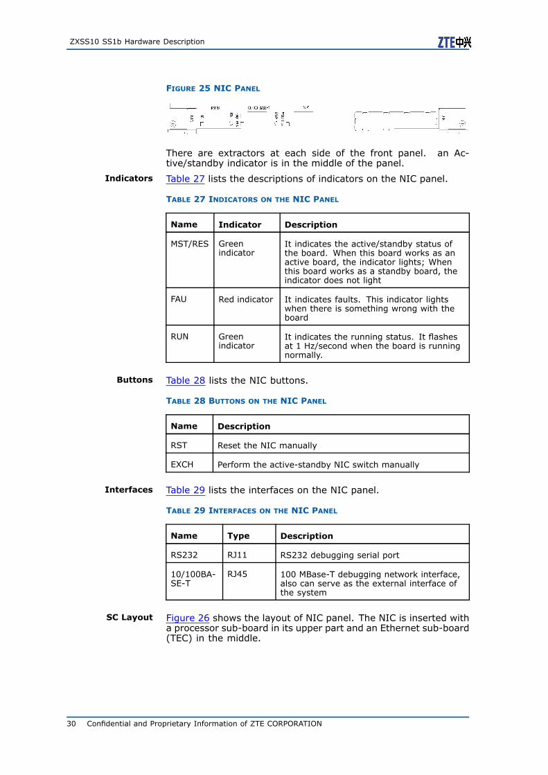
Panel Description Figure 25 shows the NIC panel.
Confidential and Proprietary Information of ZTE CORPORATION 29
ZXSS10 SS1b Hardware Description
FIGURE 25 NIC PANEL
There are extractors at each side of the front panel. an Ac-tive/standby indicator is in the middle of the panel.
Indicators Table 27 lists the descriptions of indicators on the NIC panel.
TABLE 27 INDICATORS ON THE NIC PANEL
Name Indicator Description
MST/RES Greenindicator
It indicates the active/standby status ofthe board. When this board works as anactive board, the indicator lights; Whenthis board works as a standby board, theindicator does not light
FAU Red indicator It indicates faults. This indicator lightswhen there is something wrong with theboard
RUN Greenindicator
It indicates the running status. It flashesat 1 Hz/second when the board is runningnormally.
Buttons Table 28 lists the NIC buttons.
TABLE 28 BUTTONS ON THE NIC PANEL
Name Description
RST Reset the NIC manually
EXCH Perform the active-standby NIC switch manually
Interfaces Table 29 lists the interfaces on the NIC panel.
TABLE 29 INTERFACES ON THE NIC PANEL
Name Type Description
RS232 RJ11 RS232 debugging serial port
10/100BA-SE-T
RJ45 100 MBase-T debugging network interface,also can serve as the external interface ofthe system
SC Layout Figure 26 shows the layout of NIC panel. The NIC is inserted witha processor sub-board in its upper part and an Ethernet sub-board(TEC) in the middle.
30 Confidential and Proprietary Information of ZTE CORPORATION

Chapter 2 Foreground Shelf
FIGURE 26 NIC LAYOUT
SC Jumpers Table 30 lists the descriptions of jumpers and pins on NIC.
TABLE 30 JUMPERS AND PINS ON THE NIC PANEL
Name Description
X2 Bank A or Bank B selection jumpers (two choices uponboot of processor board. A indicates that board boots fromBOOT in processor sub-board. B indicates that the boardboots from the two Flashes in the main board
X5 Active jumper of the processor card. Normally, it is theactive jumper if the board serves as the single processorboard
X11 CPU emulation interface
X18 For the download cable of LITTICE standard interface
Caution:
For the detailed definition of jumpers, refer to PCB silkscreen.
Confidential and Proprietary Information of ZTE CORPORATION 31

ZXSS10 SS1b Hardware Description
TIC
Functions Transport Interface Card, or TIC in short, is a back plug-in card.It can be installed in slot 32 of ZXSS10 SS1b.
TIC provides 10/100 M Ethernet ports from SC to background, andto 100 M Ethernet port of active and standby NICs. It also providesthree RS232 interfaces and two RS485 interfaces. One 1 G Eth-ernet port is reserved for active/standby output. It accomplishesthe following functions:
� Lead in signals from active and standby 100 M Ethernet portsof three pairs of NICs, converts them, and outputs signals con-verted.
� Reserve the active and standby output of a 1 G Ethernet port.
� Provide three external RS232 serial ports and two RS485 serialports.
Panel Description Figure 27 shows the TIC panel.
FIGURE 27 TIC PANEL
There are extractors on each side of the front panel. A powerindicator is located in the left part of the panel, followed by fiveRJ45 sockets, which provide one 1 G Ethernet port (reserved) andfour 100 M Ethernet ports.
There are five RJ11 sockets on the right part of the front panel,providing five serial ports (two RS-485 signals and three RS-232signals) from SC/SSC.
Indicators Table 31 lists the descriptions of the indicator on TIC panel.
TABLE 31 INDICATOR ON THE TIC PANEL
Name Indicator Description
PWR GreenIndicator
It indicates the power status. When theboard is running normally, this indicatorlights; When something wrong occurs tothe board, it does not light
Interfaces Table 32 shows the interfaces on the TIC panel.
32 Confidential and Proprietary Information of ZTE CORPORATION

Chapter 2 Foreground Shelf
TABLE 32 INTERFACES ON THE TIC PANEL
Name Type Description
1000 BASE-T RJ45 1000 MBase-T Ethernet port, reserved forsystem upgrading
10/100BASE-T1
RJ45 100 MBase-T Ethernet port, externalactive/standby exporter of NICs 13 and 14
10/100BASE-T2~3
RJ45 100 MBase-T Ethernet port, externalactive/standby exporter of NICs 11, 12, 9and 10 (only for the ZXSS10 SS1b)
OAM LAN RJ45 100 MBase-T Ethernet port, the backgroundoperation and management interface of thesystem
RS4851~2 RJ11 RS485 interface, external serialcommunication extension interface
RS2321~3 RJ11 RS232 interface, external serialcommunication extension interface
CSN
Functions Center Switch Network Card, or CSN in short, is a front plug-incard. It is used in a system which has three or more than threeshelves which are connected together. The shelf with a CSN iscalled a main shelf, the other shelves are all slave shelves. CSNcan only be plugged in slots 7 and 8 in shelves 1, 7 and 9. Whenthe main board uses a CSN, it must use GNIC at the same time.
Figure 28 shows the position of CSN in shelf 1. Two CSN boardsare in slots 7 and 8.
FIGURE 28 POSITION OF CSN IN A ZXSS10 SS1B SHELF
CSN provides the following functions:
Confidential and Proprietary Information of ZTE CORPORATION 33
ZXSS10 SS1b Hardware Description
� It provides 24 100 M and 4 1000 M Ethernet switching networkswhich have two layers.
� It provides more than 8 trunks, in which, every trunk containsmore than 3 duplexes.
� It provides a SC board managed Ethernet control channel toconnect to the SSN board.
� It provides a backup channel 485 bus which is managed by SCboard.
� It provides a debugging 100 M Ethernet interface and a RS232serial port.
� It provides hot-swap function and software/hardware inter-faces to implement HA with SC.
� It provides a hot switching function. Active and standbyswitching can be made through operations on hardware andsoftware.
� Shelf type, shelf number and the slot number of the board canbe given on the backplane.
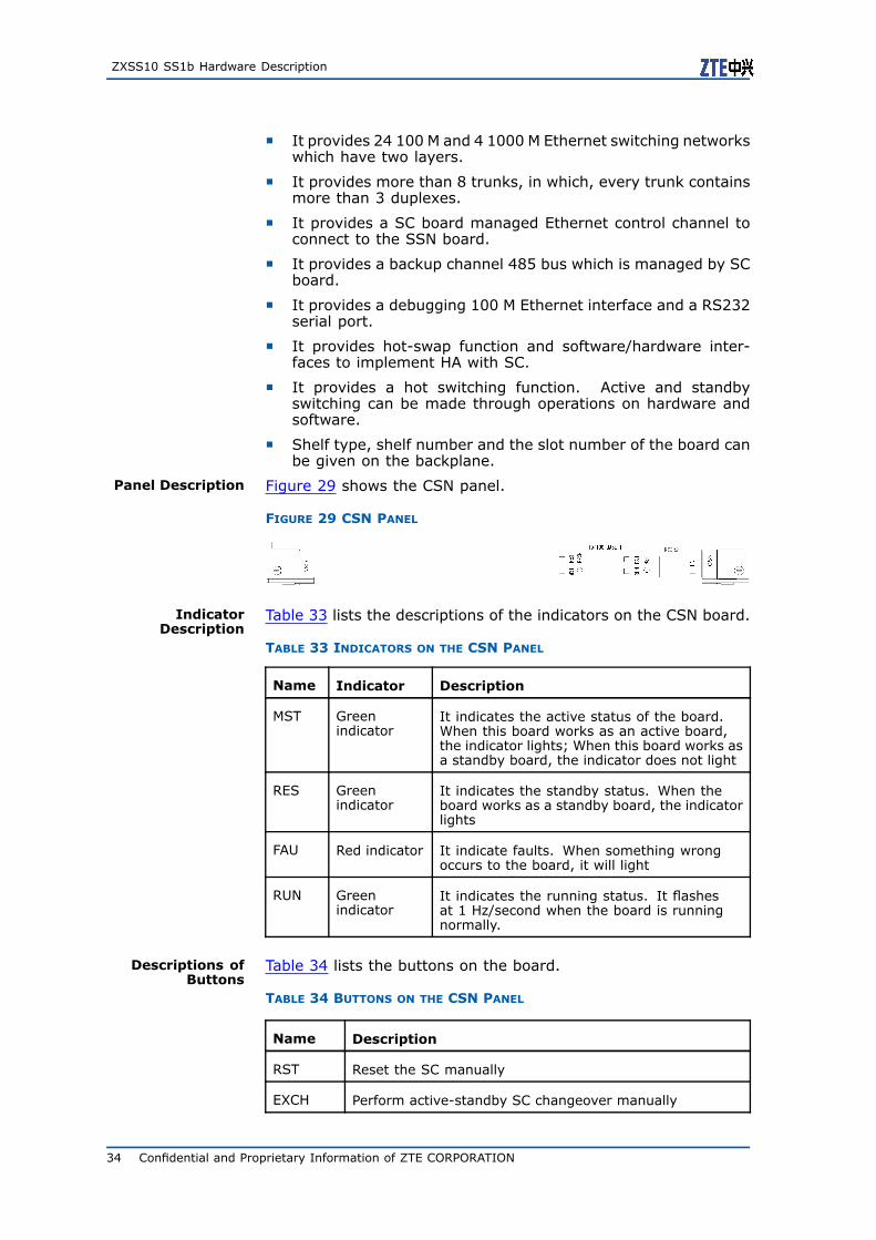
Panel Description Figure 29 shows the CSN panel.
FIGURE 29 CSN PANEL
IndicatorDescription
Table 33 lists the descriptions of the indicators on the CSN board.
TABLE 33 INDICATORS ON THE CSN PANEL
Name Indicator Description
MST Greenindicator
It indicates the active status of the board.When this board works as an active board,the indicator lights; When this board works asa standby board, the indicator does not light
RES Greenindicator
It indicates the standby status. When theboard works as a standby board, the indicatorlights
FAU Red indicator It indicate faults. When something wrongoccurs to the board, it will light
RUN Greenindicator
It indicates the running status. It flashesat 1 Hz/second when the board is runningnormally.
Descriptions ofButtons
Table 34 lists the buttons on the board.
TABLE 34 BUTTONS ON THE CSN PANEL
Name Description
RST Reset the SC manually
EXCH Perform active-standby SC changeover manually
34 Confidential and Proprietary Information of ZTE CORPORATION
Chapter 2 Foreground Shelf
Descriptions ofJumpers and Pins
Table 35 lists the descriptions of jumpers and pins.
TABLE 35 JUMPERS AND PINS ON THE CSN PANEL
Name Description
X9 CPU JTAG interface
X10 EPLD JTAG interface
LocationDescription
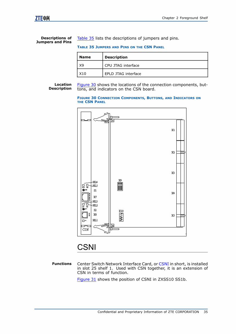
Figure 30 shows the locations of the connection components, but-tons, and indicators on the CSN board.
FIGURE 30 CONNECTION COMPONENTS, BUTTONS, AND INDICATORS ONTHE CSN PANEL
CSNI
Functions Center Switch Network Interface Card, or CSNI in short, is installedin slot 25 shelf 1. Used with CSN together, it is an extension ofCSN in terms of function.
Figure 31 shows the position of CSNI in ZXSS10 SS1b.
Confidential and Proprietary Information of ZTE CORPORATION 35
ZXSS10 SS1b Hardware Description
FIGURE 31 POSITION OF CSNI IN A ZXSS10 SS1B SHELF
Panel Description Figure 32 shows the CSNI panel.
FIGURE 32 CSNI PANEL
36 Confidential and Proprietary Information of ZTE CORPORATION

Chapter 2 Foreground Shelf
Location of thePlug-in Units and
Indicators
Figure 33 shows the connection components and indicators on theCSNI board.
FIGURE 33 CONNECTION COMPONENTS AND INDICATORS ON THE CSNIPANEL
GNIC
Functions The basic functions of GNIC and NIC are more or less the same,but GNIC has a more powerful processing performance. The net-work interface board GNIC provides the Ethernet-based interfaceand the routing function. The GNIC board provides the SoftSwitchcontrol equipment with external network interfaces and supportsthe following features:
� It provides a powerful processing performance. The board isdesigned based on the dedicated network processor. A specialmicro-drive is used in it to transfer Ethernet packets in highspeed.
� It provides an independent 100 MBase-T interface which isused to communicate with the system main control.
� It provides a gigabit network interface which is connected tothe CSN board.
� It provides a gigabit network interface which is used to connectthe external network.
� It provides four 100M network interfaces which is used to con-nect the external network.
� Provide hot-swap function and software/hardware interfaces toimplement HA with SC.
Confidential and Proprietary Information of ZTE CORPORATION 37
ZXSS10 SS1b Hardware Description
� It provides a RS485 interface which is used as a standby chan-nel to communicate with SC.
� Provides board position signals and shelf ID information.
GNIC Panel Figure 34 shows the GNIC panel. Two ejector levers are on theends of the panel. Other components set from left to right are yel-low HS indicator, debug serial port, reset button, red fault indica-tor, green running indicator, Gigabit Ethernet RJ45 socket used forconnecting the external network, active/standby switchover but-ton, green indicator for active state, and four 100M Ethernet in-terfaces.
FIGURE 34 GNIC PANEL
Indicators Table 36 lists the descriptions of the indicators on the GNIC board.
TABLE 36 INDICATORS ON THE GNIC PANEL
Name Indicator Description
MST/RES Greenindicator
It indicates the active/standby status of theboard. When this board works as an activeboard, the indicator lights; When this boardworks as a standby board, the indicatordoes not light
FAU Redindicator
It indicates faults. This indicator lights whenthere is something wrong with the board
RUN Greenindicator
It indicates the running status. It flashesat 1 Hz/second when the board is runningnormally
Buttons Table 37 lists the descriptions of GNIC buttons.
TABLE 37 GNIC BUTTONS ON THE GNIC PANEL
Name Description
RST Reset the NIC manually
EXCH Perform the active-standby NIC changeovermanually
Interfaces Table 38 lists the descriptions of GNIC interfaces.
38 Confidential and Proprietary Information of ZTE CORPORATION

Chapter 2 Foreground Shelf
TABLE 38 INTERFACES ON THE GNIC PANEL
Name Type Description
RS232 RJ11 RS232 debug serial port
1000BASE-T RJ45 Gigabit Ethernet interface used forconnecting the external network
100 BASE-T 4XRJ45 Four 100 M Ethernet interfaces used forconnecting external networks
Caution:
Because the architecture of GNIC differs from that of NIC, the net-work interface on the GNIC panel cannot be used for debugging.
Layout Figure 35 shows the layout of GNIC.
FIGURE 35 GNIC LAYOUT
Jumpers and Pins Table 39 lists the descriptions of jumpers and pins of GNIC panel.
Confidential and Proprietary Information of ZTE CORPORATION 39

ZXSS10 SS1b Hardware Description
TABLE 39 JUMPERS AND PINS ON THE GNIC PANEL
Name Description
X2 JTAG programming interface of the D4 CPLD
X11 JTAG interface of the D6 FPGA
D21 SO-DIMM SDRAM socket
Caution:
For the detailed definition of jumpers, refer to PCB silkscreen.
Shelf PowerSPWBP
Functions SPWBP combines two –48 V power supplies (which are mutuallybacked up) into one and provides ZXSS10 SS1b with –48 V powersupply. It also performs filtering, lightning protection, and anti-reverse-connection on two –48 V inputs, and selects and controlstwo –48 V power supplies by using air breaker.
SPWBP consists of a filter, a POWI, an air breaker, and a lightningarrester.
Working Principle Anti-EMI filtering circuit can:
1. Effectively filters the conducted interference of within theZXSS10 SS1b system. Thus the conducted interference valuemeasured at the input end of the power distribution boxreduced greatly.
2. Improves the anti-interference capability of the system andreduces the electromagnetic sensitivity of the system.
Figure 36 illustrates the working principle of POWI of SPWBP.
40 Confidential and Proprietary Information of ZTE CORPORATION

Chapter 2 Foreground Shelf
FIGURE 36 WORKING PRINCIPLE OF POWI
TPOWP
Functions TPOWP provides ZXSS10 SS1b with a backup line of –60 V powersupply. It also performs filtering, lightning protection, and air-cooling control.
Working Principle SPWBP consists of a POWI and a TPOWT.
1. POWI: When configuring two –60 V power inputs on the rack,segregate the two inputs by using the segregating diode andthen parallel the outputs to the copper bus-bar to power thedevice. Two –60 V power inputs functions as hot backup mu-tually.
2. TPOWP: Monitoring the output voltage and the running statusof power box in real-time.
Figure 37 illustrates the working principle of TPOWP.
FIGURE 37 WORKING PRINCIPLE OF TPOW
Confidential and Proprietary Information of ZTE CORPORATION 41

ZXSS10 SS1b Hardware Description
SPWBF
Functions SPWBF monitors the following in real-time:
� Voltage value of –48 V power supply (combined of two –48 Vpower supplies) output by power distribution box.
� Power supply of the system (including status of left and rightpower supplies, over/under voltage of right and left power sup-plies, and working status of the ventilation system)
� Operation status of fans.
Working Principle SPWFB consists of a TPOWT and four 48 V fans.
Detection circuit of TPOWT adopts a single-chip microcomputersystem. It converts analog voltage to 12-bit serial digital signalthrough A/D transformer and inputs signal to I/O port of CPU. CPUprocesses signal, implementing real-time monitoring of -48 V out-put voltage.
I/O port of CPU monitors the fan status (normal/abnormal) in real-time. Because coil circuit in fan is easily broken, a rectifying diodeis concatenated to each channel, and comparator is used to de-tect the voltage at the two ends of the rectifier bulb to check thatwhether the fan circuit is broken.
When a fan is damaged, the fuse of the fan is burnt. As a result,there is no current on diode, and the fan fault can be detected.
When any fan fails, indicator on the front panel gives an alarm.In addition, CPU reports voltage value of A/D conversion result for-48 V output and working status of fan through 485 bus.
Working principle of TPOWT is illustrated in following Figure 38.
FIGURE 38 WORKING PRINCIPLE OF TPOWT
42 Confidential and Proprietary Information of ZTE CORPORATION
Chapter 2 Foreground Shelf
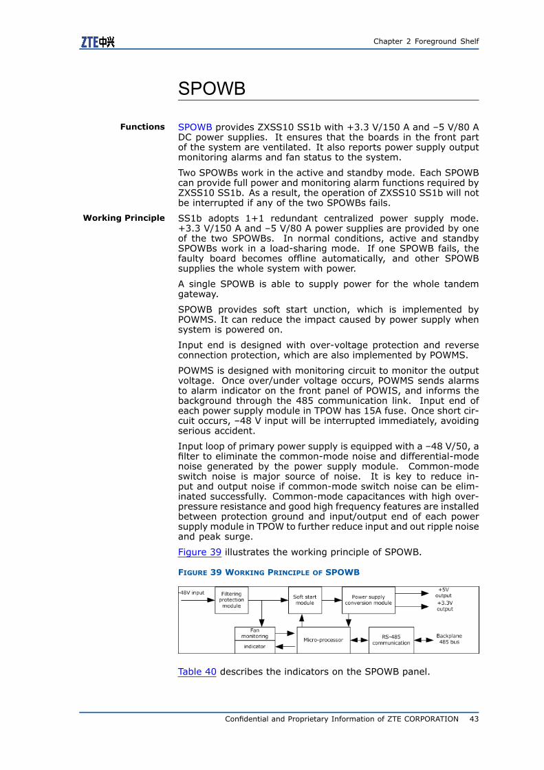
SPOWB
Functions SPOWB provides ZXSS10 SS1b with +3.3 V/150 A and –5 V/80 ADC power supplies. It ensures that the boards in the front partof the system are ventilated. It also reports power supply outputmonitoring alarms and fan status to the system.
Two SPOWBs work in the active and standby mode. Each SPOWBcan provide full power and monitoring alarm functions required byZXSS10 SS1b. As a result, the operation of ZXSS10 SS1b will notbe interrupted if any of the two SPOWBs fails.
Working Principle SS1b adopts 1+1 redundant centralized power supply mode.+3.3 V/150 A and –5 V/80 A power supplies are provided by oneof the two SPOWBs. In normal conditions, active and standbySPOWBs work in a load-sharing mode. If one SPOWB fails, thefaulty board becomes offline automatically, and other SPOWBsupplies the whole system with power.
A single SPOWB is able to supply power for the whole tandemgateway.
SPOWB provides soft start unction, which is implemented byPOWMS. It can reduce the impact caused by power supply whensystem is powered on.
Input end is designed with over-voltage protection and reverseconnection protection, which are also implemented by POWMS.
POWMS is designed with monitoring circuit to monitor the outputvoltage. Once over/under voltage occurs, POWMS sends alarmsto alarm indicator on the front panel of POWIS, and informs thebackground through the 485 communication link. Input end ofeach power supply module in TPOW has 15A fuse. Once short cir-cuit occurs, –48 V input will be interrupted immediately, avoidingserious accident.
Input loop of primary power supply is equipped with a –48 V/50, afilter to eliminate the common-mode noise and differential-modenoise generated by the power supply module. Common-modeswitch noise is major source of noise. It is key to reduce in-put and output noise if common-mode switch noise can be elim-inated successfully. Common-mode capacitances with high over-pressure resistance and good high frequency features are installedbetween protection ground and input/output end of each powersupply module in TPOW to further reduce input and out ripple noiseand peak surge.
Figure 39 illustrates the working principle of SPOWB.
FIGURE 39 WORKING PRINCIPLE OF SPOWB
Table 40 describes the indicators on the SPOWB panel.
Confidential and Proprietary Information of ZTE CORPORATION 43
ZXSS10 SS1b Hardware Description
TABLE 40 INDICATORS ON THE SPOWB PANEL
Name Indicator Description
PWR Redindicator
It lights when there is no power supply,or power supply failure occurs.
PWR Greenindicator
It lights when the power supply isnormal.
FAN Redindicator
It lights when a fault occurs to the fan.
TPOWB
Functions The power supply box TPOWB consists of a TPOW, a POWMS and aPOWBG. TPOW provides ZXSS10 SS1b with +3.3V/300A, +5V/80ADC power supply.
Input voltage–60V±20% (–50V ~–72V)
Output capacity+3.3V: 300A+5V: 80A
Working Principle The principle is the same with that of SPOWB, except the inputvoltage which is –60 V.
44 Confidential and Proprietary Information of ZTE CORPORATION
C h a p t e r 3
Background DatabaseServer
Table of ContentsOverview..........................................................................45SUN Server Background .....................................................45PC Server Background........................................................47
OverviewOperators can save static service data, configurations and userdata in the background data server of ZXSS10 SS1b. The fore-ground can read and write data through reliable interfaces.
Both SUN servers and PC servers can be used as the backgrounddata server.
SUN Server BackgroundIf SUN Server is used as the background server of ZXSS10 SS1b,SUN Fire V240 or the ones with higher performance should be thechoice. The following is the description of SUN Fire V240.
Figure 40 shows SUN Fire V240 and Table 41 lists its detailed con-figurations.
Confidential and Proprietary Information of ZTE CORPORATION 45

ZXSS10 SS1b Hardware Description
FIGURE 40 SUN FIRE V240
TABLE 41 PARAMETERS OF SUN FIRE V240
Basics
Type Entry-level network
Class Rack style
Structure 2U
Processor
CPU type UltraSPARC IIIi
CPU frequency (MHz) 1500
CPU description Standard disposition: Two CPUs
Maximum number ofprocessors
2
CPU level-2 buffer 1MB
Main board
Extended Slot 3
Memory
Memory type ECC DDR
Memory size 2GB
Maximum memorysize
16GB
Storage
Hard disk space 2*73GB
46 Confidential and Proprietary Information of ZTE CORPORATION

Chapter 3 Background Database Server
Basics
Hard disk type SCSI
Maximum number ofhot plug hard disks
4 Ultra160SCSI 73/146GB hard disks at most
IDE controller ATA 33/66
SCSI controller Ultra 160 SCSI
CD-ROM driver One Slim-line ATAPI DVD-ROM (optional)
Network
Network controller Four 10/100/1000Base-T Ethernet interfaces
Power performance
Power Hot plug redundancy power
Number pf power 2
Voltage 100-240 V
Power output (W) 546
Appearance
Size 87.66 * 425 * 635 mm
Weight 22.4 Kg
Software system
Systems Solaris 10 (Hardware version 03/05 or higher),Solaris 9 (Hardware version 09/04 or higher),Solaris 8 (Hardware version 02/04 or higher)
Environment requirement
Working temperature 5 ℃~40 ℃
Working humidity 10%~90%, frozen-free
Storage temperature -40 ℃~65 ℃
Storage humidity 93%, frozen-free
PC Server BackgroundIf PC Server is used as the background server of ZXSS10 SS1b,HP DL380 G5 or the ones with higher performance should be thechoice. The following is the description of HP DL380 G5.
Figure 41 shows HP DL380 G5.
Confidential and Proprietary Information of ZTE CORPORATION 47

ZXSS10 SS1b Hardware Description
FIGURE 41 HP DL380 G5
Table 42 lists the detailed information.
TABLE 42 PARAMETERS OF HP DL380 G5
Basics
Class Rack style
Struc-ture
2U
Processor
CPU type Xeon
CPU fre-quency(MHz)
3000
CPU de-scription
Standard disposition: two Xeon 5160 CPUs
Maxi-mumnumberof pro-cessors
2
CPUlevel-2buffer
1*4 MB
Main board
Mainboardchipset
Intel 5000 P
FSB (bus)
1333 MHz
Ex-tendedslot
Three PCI Express X4, two PCI Express X8
Memory
48 Confidential and Proprietary Information of ZTE CORPORATION

Chapter 3 Background Database Server
Basics
Memorytype
FB-DIMM
Memorysize
4 GB
Maxi-mummemorysize
32 GB
Storage
Harddiskspace
No
Harddisk type
SAS
Maxi-mumspaceof harddisks
576 GB
Numberofinternalharddisks
8*72 GB hot plug SFF SAS hard disks
Externaldriver
IDE DVD-ROM/CDRW combined driver
Maxi-mumnum-ber ofhot plugharddisks
8
Diskarraycard
Intelligent disk array P400 controller
IDE con-troller
Ultra ATA 100
CD-ROMdriver
IDE DVD-ROM/CDRW combined driver
Flopydiskdrive
None
Network
Networkcontrol-ler
Embedded dual 1000 M NC373i network card
Confidential and Proprietary Information of ZTE CORPORATION 49

ZXSS10 SS1b Hardware Description
Basics
Display performance
Displaychip
Integrated ATI ES1000 1280 * 1024 * 16M (32 M displaymemory)
Interface type
Stand-ard in-terface
One serial port, one mouse positioning device interface,one display card interface, one keyboard interface,twoVGAs (one on the front side and one on the back side), twoRJ-45 network interface, one iLO 2 remote managementinterface, five USB 2.0 interfaces (two on the front side,two on the back side, one builds in)
Other parameters
Others Comply with standards of ACPI 2.0, PCI 2.2, WOL, Microsoftcertification and USB 2.0
Management and security
Manage-menttools
Integrated Lights-Out 2 (iLO 2), HP Systems InsightManager, SmartStart, management proxy, redundant ROM,remote flash memory ROM, ROM-based RBSU, integratedmanagement logs, ASR, dynamic sector recovery, driverparameter tracing, fault warranty (including CPU, SCSIhard disk driver and memory)
Security Power on password, keyboard password, floppy control,floppy disk starting control, QuickLock, network servermode, parallel and serial interface control, administratorpassword, disk configuration locking
Power performance
Power Optional AC hot plug power
Numberofpowers
1
Voltage 100-132 VAC200-240 VAC,50/60HZ
Poweroutput(W)
546
Appearance
Size 85.9 * 445.4 * 660.7mm (with base and front cover)
Weight About 27.22Kg
Software system
Sysy-tems
Windows 2000/2003 Server, Novell NetWare, SCOUnixWare, OpenServer, LINUX (Red Hat, SuSE), SCOUnixWare, OpenServer, VMware Virtualization Software
Environment
50 Confidential and Proprietary Information of ZTE CORPORATION

Chapter 3 Background Database Server
Basics
Workingtemper-ature
10℃-35℃
Workinghumidity
10%-90% (Rh), maximum 28℃ in a condition of 90%humidity
Storagetemper-ature
-30℃-60℃
Storagehumidity
5%-95% (Rh), maximum 38.7℃ in a condition of 95%humidity
Confidential and Proprietary Information of ZTE CORPORATION 51
ZXSS10 SS1b Hardware Description
This page is intentionally blank.
52 Confidential and Proprietary Information of ZTE CORPORATION

Figures
Figure 1 ZXSS10 SS1b Cabinet............................................. 1
Figure 2 Cabinet Structure................................................... 2
Figure 3 Power Structure ..................................................... 3
Figure 4 Plane Structure of Power Shelf ................................. 4
Figure 5 Typical Configuration of ZXSS10 SS1b Rack S ............ 6
Figure 6 Typical Configuration of ZXSS10 SS1b Rack G1 .......... 7
Figure 7 Typical Configuration of ZXSS10 SS1b Multi-rack ........ 8
Figure 8 Typical Configuration of ZXSS10 SS1b Rack G3 .......... 9
Figure 9 Front View of a ZXSS10 SS1b Shelf .........................11
Figure 10 Back View of a ZXSS10 SS1b Shelf ........................12
Figure 11 Front View of a ZXSS10 SS1b Shelf .......................13
Figure 12 Back View of a ZXSS10 SS1b Shelf ........................14
Figure 13 ZXSS10 SS1b Board Slot (12U Plug-in Box, Front
View)...............................................................14
Figure 14 ZXSS10 SS1b Board Slot (12U Plug-in Box, Back
View)...............................................................15
Figure 15 SC Panel ............................................................18
Figure 16 SC Layout ..........................................................19
Figure 17 ESC Panel...........................................................20
Figure 18 SSN Panel ..........................................................22
Figure 19 SSN Layout ........................................................23
Figure 20 SSNI Panel .........................................................24
Figure 21 SSNI Layout .......................................................25
Figure 22 SPC Panel...........................................................26
Figure 23 SPC Layout.........................................................27
Figure 24 ESPC Panel .........................................................28
Figure 25 NIC Panel ...........................................................30
Figure 26 NIC Layout .........................................................31
Figure 27 TIC Panel ...........................................................32
Figure 28 Position of CSN in a ZXSS10 SS1b Shelf .................33
Figure 29 CSN Panel ..........................................................34
Figure 30 Connection Components, Buttons, and Indicators
on the CSN Panel...............................................35
Figure 31 Position of CSNI in a ZXSS10 SS1b Shelf ................36
Confidential and Proprietary Information of ZTE CORPORATION 53

ZXSS10 SS1b Hardware Description
Figure 32 CSNI Panel .........................................................36
Figure 33 Connection Components and Indicators on the
CSNI Panel .......................................................37
Figure 34 GNIC Panel ........................................................38
Figure 35 GNIC Layout .......................................................39
Figure 36 Working Principle of POWI ....................................41
Figure 37 Working Principle of TPOW....................................41
Figure 38 Working Principle of TPOWT ..................................42
Figure 39 Working Principle of SPOWB..................................43
Figure 40 SUN Fire V240 ....................................................46
Figure 41 HP DL380 G5 ......................................................48
54 Confidential and Proprietary Information of ZTE CORPORATION

Tables
Table 1 Cabinet Parameters.................................................. 4
Table 2 Common Configurations of a Shelf ............................15
Table 3 ZXSS10 SS1b Boards ..............................................17
Table 4 Indicators on the SC Panel .......................................18
Table 5 Buttons on the SC Panel ..........................................18
Table 6 Interfaces on the SC Panel .......................................18
Table 7 Pins and Jumpers on the SC Panel.............................19
Table 8 Indicators on the ESC Panel .....................................20
Table 9 Buttons on the ESC Panel ........................................21
Table 10 Interfaces on the ESC Panel ...................................21
Table 11 Pins and Jumpers on the ESC Panel .........................21
Table 12 Indicators on the SSN Panel ...................................22
Table 13 Buttons on the SSN Panel ......................................23
Table 14 Interfaces on the SSN Panel ...................................23
Table 15 Jumpers and Pins on the SSN Panel.........................24
Table 16 Indicator on the SSNI Panel....................................24
Table 17 Interfaces on the SSNI Panel ..................................24
Table 18 SWITCH S2 (In the Middle of SSNI).........................25
Table 19 Indicators on the SPC Panel....................................26
Table 20 Button on the SPC Panel ........................................26
Table 21 Interfaces on the SPC Panel ...................................27
Table 22 Jumpers and Pins on the SPC Panel .........................27
Table 23 Indicators on the ESPC Panel ..................................28
Table 24 Button on the ESPC Panel ......................................28
Table 25 Interfaces on the ESPC Panel..................................29
Table 26 Pins and Jumpers on the ESPC Panel .......................29
Table 27 Indicators on the NIC Panel ....................................30
Table 28 Buttons on the NIC Panel .......................................30
Table 29 Interfaces on the NIC Panel....................................30
Table 30 Jumpers and Pins on the NIC Panel .........................31
Table 31 Indicator on the TIC Panel......................................32
Table 32 Interfaces on the TIC Panel ....................................33
Table 33 Indicators on the CSN Panel ...................................34
Table 34 Buttons on the CSN Panel ......................................34
Confidential and Proprietary Information of ZTE CORPORATION 55

ZXSS10 SS1b Hardware Description
Table 35 Jumpers and Pins on the CSN Panel.........................35
Table 36 Indicators on the GNIC Panel..................................38
Table 37 GNIC Buttons on the GNIC Panel.............................38
Table 38 Interfaces on the GNIC Panel..................................39
Table 39 Jumpers and Pins on the GNIC Panel .......................40
Table 40 Indicators on the SPOWB Panel...............................44
Table 41 Parameters of SUN Fire V240..................................46
Table 42 Parameters of HP DL380 G5 ..................................48
56 Confidential and Proprietary Information of ZTE CORPORATION
Glossary
CPU- Central Processing Unit
CSN- Center Switch Network (Card)
CSNI- Center Switch Network Interface (Card)
ESC- Enhanced System Control
GNIC- Gigabit Ethernet Network Interface Card
NIC- Network Interface Card
POWI- Power Isolation Board
SC- System Control (Card)
SPC- System Protocol Control (card)
SPOWB- SoftSwitch Power Box
SPWBF- SoftSwitch Power Box of Fan
SPWBP- SoftSwitch Power Box of Part
SSN- System Switching Network (card)
SSNI- System Switching Network Interface (Card)
TIC- Transport Interface Card
Confidential and Proprietary Information of ZTE CORPORATION 57