assii · e i oma o e s aiue wi eecio es o was ieica oa mae a age o 1 e es seu is sow i es os 7 a...
TRANSCRIPT

(1.: ,, ,...7-,.."7ZL-g3F-------
A.....vrm.)0 I))
ASSIFI Deau S
OssifiadL'eguara rxx Classiflal Sadvm.e.to
SANDIA SYSTEMATIC DECLASSIFICATION REVMW
DOWNGRADING OR DECLASSIFICATION STAMP
C ASSIFICATION CHANGEDTO: AUTHORTY: ILle dill^-14-'
RECORD ID: q C15-103 92,C"PERSON CHAN
PERSONDATED:p.
IJNCLASSIF
YR. W. J. DENISON - 1224
Attn: Mr. H. M. Jones - 1224-2
Re: Static Tests of TX-28-X1 Rear Subassembly
t,1036
OCT 2"19531953Case No. 771.00Ref. Sym: 1612 (809)Project No. TM-853File: TX-28, 3-2
aummaty...PLEL:10111
Static tests on the TX-28results:
X1 Rear Subassembly yielded the following
1. Pin joint separation n the final design cases occurred at less than2,000 pounds axial p 1 on the small parachute lugs.
2. The rear lug and lug stop withstood a proof load of 8,000 pounds(240 per cent design limit) with no indication of yielding orjailure.
3. A vertical load of 425 pounds (180 per cent design limit) applied tothe small parachute cone resulted in negligible permanent displacement.
4. A vertical load of 221C pounds (150 per cent design limit) applied tothe MC-926 case resulted in 0.088 inch maximum permanent displacement.
5. Fin failure occurred at a simulated air load of 1860 pounds (262 percent design limit) applied evenly over the fin surface.
6. Pin joint separationdegrees with the cas
7. Each small parachutedesign limit) with n
occurred at 2,170 pounds pull at an angle of 12axis.
lug withstood 12,000 pounds load (240 per centindication of yielding or failure .-
8. OCI 24When loaded by the rear lugs, the rear case section failed at 27,3uupounds (137 per cent design limit). The lugs and lug stops rqrinedundamaged.
9. A simulated main parachute load of 80,000 pounds at an angle of 20degrees to the case axis produced a maximum principal stress of52,030 psi in the rear ring of the forward case section. The casesection failei at 82,580 pounds pull applied at a 20-degree angle.
•

S
1037
ASSIFIED OCT 1958Ref. Sym: 1612 (809)
-2- Project No. TN-853
s to determine the structural adequacy of theThe following tests were performed:
No. 1 - Pin joint se.No. 2 - Proof test of
(240 per centNo 3 - Vertical load
on small paraNo 4 - Vertical load
on main paracNo. 5 - Simulated airNo. 6 - Pin joint se.
12 degrees toNo. 7 - Test to failNo. 8 - Test to fail
AC-926 case.No. 9 - Simulated ma
at 15-degreeto failure w
ration by axial load.rear lug and lug stop to 8,000 poundsdesign limit).of 425 pounds (180 per cent design limit)hute cone.of 2210 pounds (150 per cent design limit)ute case.load on fins to failure.ration by a load applied at an angle ofthe case axis.e of small parachute lugs.e of rear lug and lug stop installed in
parachute load of 80,000 pounds appliednd 20-degree angles, followed by testing
th a load at an angle of 20 degrees.
Test Nor I was performedall performed on the sam
The test was performed iDivision 1224 to Divisio1224-2, and Mr. D. F. La
Function of gztect Teste
on three different cases. The other tests werecase or on various parts of it.
accordance with a Work Order Authorization from1612, dated Nay 29, 1958. Mr. H. M. Jones,ge, 1282-2, were the consultants.
The TX-28-X1 Rear Subasthe TX-28-X1 weapo.
81mmary f_fant_lpsts
Numerous tests have beeTwo of these involved 1
Results of a static tesare given in the reportline, dated Narch 6, 19parachute lug ring andpounds simulated chute
mLly contains the pilot and main parachutes for
performed on the TX-28-X1 and its components.d conditions similar to loads in this test.
simulating main parachute loads on the rear case$174,±,Jc Test of. TX-28/X1 Aft Gage PIT4obyte Lug8, VIL-548, Ref. Sym: 1612 (486). One TX-28/X1ft case, DS(1224)79328, was loaded to 145,000pad at an angle of 15 degrees with the longitudinal
CLASSIFIED

IJNC ASSIFIED •
7 1958 103SRef. Symt 1612 (809)
-3- Project No, TM-853
occurred. Another TX-201 aft case, Dwg.110,000 pounds at 15 degrees without failure.f 106,000 pounds making an angle of 20 degrees
Mr. W. J. Denison - 1224
axis of the case. No damagNo DL-10021, was loaded toFailure occurred at a pullwith the longitudinal axis.
Static tests to determine tsections are reported in St,-frfaivIC-P2 A t grk_ge-1612 (711). The :10-926 tai:chute load of 3,000 pounds,to the same case without ca t
e load required to separate the MC-926 casetic Test of Re1ease_Lint of OrilagSection, dated March 31, 1958, TM-760, Ref. Sym:case sections separated at a simulated pilotA vertical load of 1,960 pounds was appliedsing failure.
Figures 1 thru 10 illustrate the setups used in the different tests.
The object tested was the Tthe MC-923 parachute deployMC-926 case, main parachutesmall parachute cone. The
-28-X1 Rear Subassembly which consisted ofing ejector assembly, the MC-924 fins, thelug assemblies, rear lug assemblies, and the
design layout is given in Drawing No. DL-10269.
The following equipment was used:
1 - Simplex hydraulic jack, 30-ton capacity.2 - Simplex hydraulic asks, 60-ton capacity.2 - Blackhawk hydrauli•pumps.5 - Baldwin strain ind cators, Serial Nos. 199392, 6-46593,
391903, J-92498, a2 - Load cells, 2,000-2 - Load cells, 5,000-1 - Load cell, 10,000-8 - Calibrated pull ba1 - Two-inch pull bar,1 - Fairchild strain i1 - Patheon hydraulic1 - Hydraulic pump con1 - Sadic automatic da
(1 J-92499.ound capacity, Serial Nos. 8813 and 20871.ound capacity, Serial Nos 4898 and 2127.ound capacity, Serial No. 655.s, Serial Nos. 1, 2, 3, 4, 5, 6, 7, and 10.Serial No, 7.dicator, Yodel 101-C-2.
400,000-pcunds capacity.o]a,
processing system, Model 34-112 ML,
The following instruments:Con was used:
6 - Starrett dial indgraduation 0.001
11 - Type AX-7 biaxial120 ohms.
5 - Rectangular rosetG.F. = 1.98 + 2%,
cators, maximum range 1.00 inch, leastch.
strain gages, G.F. = 1.88 ± 2%, resistance
e strain gages made up of Type A-7 gages,resistance = 120 ohms.
U CLASSIFIED

1039
UNCMr. W. J. Denison - 1224
ASSIFIED-4-
OCT 2 3 1958
Ref. Sym: 1612 (809)Project No. TM-853
Procedure
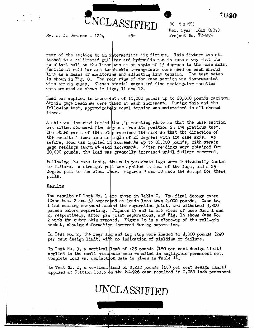
For Test No. 1 the MC-926ring on the forward end ofjig. Load was applied thrcase, with the resultant awas increased gradually un146.88, permitting separatislack was then taken up, aof the entire rase sectiondifferent cases.
se was mounted as shown in Fig. 1. A threadedthe case served as a means of attachment to theugh nylon straps over lugs in the rear of theting along the longitudinal case axis. The loadit five 1/8-inch aluminum pins sheared at Stationon of the outer skin at Station 130.625. Thed load again applied gradually until separationtook place. This test was performed on three
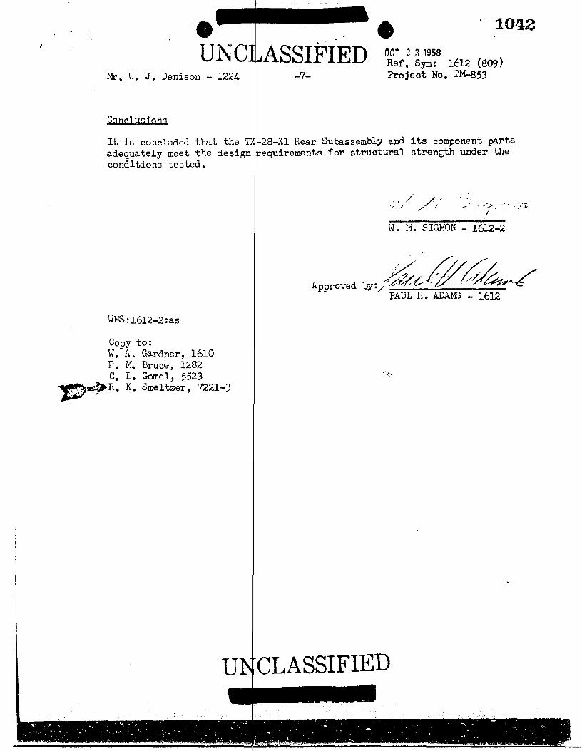
In Test No. 2, a rear lugLoad was applied through a
For Test No. 3, the complein Fig. 3. Load was appliparachute cone. The Joaddeflection readings taken
nd lug stop were mounted as shown in Fig. 2.nylon strap in increments up to 8000 pounds.
e TX-28-X1 Rear Subassembly was mounted as shownd through a 10-inch nylon strap to the smallas increased in increments up to 425 pounds witht each increment,
Test No. 4 was quite similat Station 153.5, and a 3-stead of the nylon strap.applied in incremerts upeach increment.
✓ to Test No. 3 except that the load was applied'nch steel strap padded with rubber was used in-The test setup is shown in Fig. 4. Load was2210 pounds with deflection readings taken at
For Test No. 5, the Rearwere applied to two finsfin is shown in Fig. 5).over the fin surface. Ththe fin, normal to the sfailure, with deflection
Test No. 6 was identicalload made an angle of 12The test setup is shown i
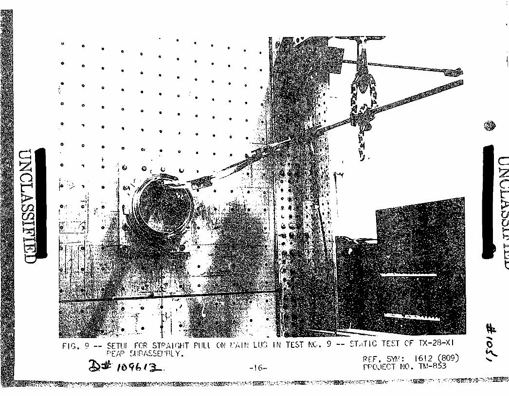
Test Nos. 7 and 8 were ccthe •-926 case was used.the six rear lugs and NerThe load was applied tirosmall parachute lugs. Thapplied gradually until
ubassembly was mounted as shown in Fig. 5. Loadsimuitaneously (for the sake of clarity, only oneRubber and wocd pads distributed the load evenlyresultant force passed through the centroid offace. Load was applied in increments until fineadings taken at each increment.
o Test No. 1 except that the resultant of theegrees with the longitudinal axis of the case.Fin. 6. Loads were applied as in Test No. 1.
bind into one test. Only the rear section ofNylon shroud lines were placed over three ofused to attach the case section co the jig.gh four steel cable loops placed over the fours test setup is shown in Fig. 7. Load wasse failure occurred.
For Test No. 9, the 2o d section of the MC-926 case, was mounted to thejig by tie threaded ring in the forward end. Nylon shroud lines were placedover each of the eight in parachute lugs and were brought out through the
U CLASSIFIED
NC SIFIEDMr. W. J. Denison - 1224
• 1040OCT 2 11958Ref. Sym: 1612 (809)Project No. T14-853—5—
rear of the section to an itacked to a calibrated pullresultant pull on the linesIndividual null bar and turline as a means of monitoriis shown in Fig. 8. The rewith strain gages. Elevenwere mounted as shown in Fi
termediate jig fixture. This fixture was at-bar and hydraulic ram in such a way that thewas at an angle of 15 degrees to the case axis.buckle arrangements were used on each shroud1g and adjusting line tension. The test setupr ring of the case section was instrumentedBiaxial gages and five rectangular rosettesgs. 11 and 12.
Load was applied in increments of 10,000 pounds up to 80,000 pounds maximum.Strain gage readings were taken at each increment. During this and thefollowing test, approximately equal tension was maintained in all shroudlines.
A shim was inserted behindwas tilted downward five dThe other parts of the setthe resultan)_ load made anbefore, load was applied igage readings taken at eac80,000 pounds, the load ma
Following the case tests,to failure. A straight pdegree pull to the other fpulls.
Results
the jig mounting plate so that the case sectiongrees from its position in the previous test.p remained the same so that the direction ofangle of 20 degrees with the case axis. Asincrements up to 80,000 pounds, with strainincrement. After readings were obtained forgradually increased until failure occurred.
he main parachute lugs were individually tested1 was applied to four of the lugs, and a 25-ur. Figures 9 and 10 show the setups for these
The results of Test No. 1(Case Nos. 2 and 3) separa1 had sealing compound aropounds before separating.2, respectively, after pi2 with the outer akin resocket, showing deformati
re given in Table I. The final design casesd at loads less than 2,000 pounds. Case No.nd the separation joint, and withstood 3,300Figulws 13 and 14 are views of case Nos. 1 andjoint separations, and Fig. 15 shows Case No.ed. Figure 16 is a close-up of the roll-pinn incurred during separation.
g and lug stop were loaded to 8,000 pounds (240h no indication of yielding or failure.
load of 425 pounds (180 per cent design limit)hute cone resulted in negligible permanent set.on data is given in Table II.
load of 2,210 pounds (150 per cent design limit)n thE, MC-926 case resulted in 0.088 inch permanent
In Test No. 2, the rear 1per cent design limit) wi
In Test No. 3, a verticalapplied to the small paraComplete load vs. deflect
In Test No. 4, a verticalapplied at Station 153.5
U CLA SSIFIED

• 11111111111111111111111111 ;1314.1UNCLASSIFIED OCT 2 :3 1958
Ref. Sym: 1612 (809)-6- Project No. TM-853
set at Station -65.0, the location of greatest deflection. Complete loadvs. deflection data is given in Table III.
In Test No. 5, failure of a fin occurred at a load of 1,860 pounds (262per cent design limit). Failure was not in the fin itself, but in thethreaded inserts in the 113-926 case holding the fin mounting bolts. Loadvs. deflection data for loads up to 1,200 pounds is given in Table IV.Tensile test specimens ta,cen after the test indicate an average yieldstrength of 43,750 psi and an ultimate strength of 48,000 psi for the finmaterial.
In Test No. 6, outer skin separation occurred at a load of 2,170 poundsand case separation at 1,770 pounds applied at a 12-degree angle with thecase axis.
In the combined running cf Test Nos. 7 and 8, case failure occurred at anaxial pull of 27,300 pounds (137 per cent design limit). Rivets holdingthe rear lug stop ring tc the outer skin either sheared or pulled through,and the ring itself fractured into three pieces. The rear lugs and lugstops remained undamaged. Figures 17 and 18 show the case and ring afterfailure. At the time of failure, the average load was 9,100 pounds oneach rear lug and 6,825 pounds on each small parachute lug. The smalllugs had been previously loaded to 12,000 pounds each (240 per cent designlimit) with no indications of yielding or failure.
Strain gage readings and calculated principle stresses for Test No. 9 aregiven in Tables V awl VI. As noted, the principle stress calculations forthe biaxial gages (Gage Nos. 1 thru 22) were based on the assumption thatthe biaxial gages were ectually mounted along the directions of principlestress; i.e., the principle stresses were assumed to be longitudinal andcircumferential.
A simulated main parachute load of 80,000 pounds at an angle of 15 degreeswith the case amds produced a maximum principle stress of 32,730 psi atstrain gage No. 30. The same load at an angle of 20 degrees produced astress of 52,030 psi at strain gage NO. 30. Case failure occurred at82,580 pounds pull at an angle of 20 degrees. Figures 19 and 20 show thecase after failure.
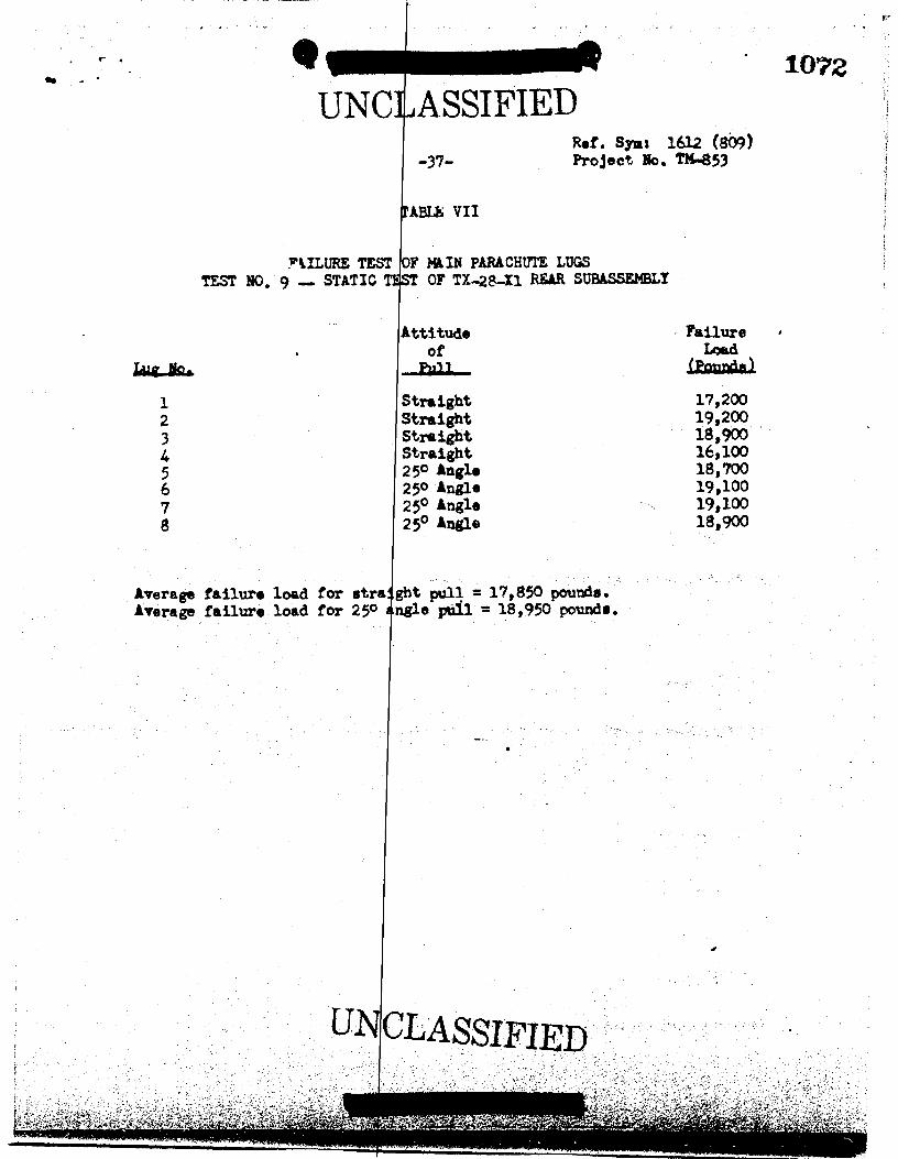
Results of pull tests on the individual main lugs are given in Table VII,Figure 21 shows the lugs after failure.
Tensilo specimens were cut from the case section following Test No. 9,and were tested to failure. Results are given in Table VIII.
Mr. W. J. Denison - 1224
UNCLASSIF
1042
UNCLASSIFIED OCT 2 11958Ref. Sym: 1612 (809)Mr. W. J. Denison - 1224 -7- Project No. TM-853
Conclusions
It is concluded that the M-28-X1 Rear Subassembly and its component partsadequately meet the design requirements for structural strength under theconditions tested.
W. M. SIGMON - 1612-2
37// Approved by :J.PAUL H. ADAM3 - 1612
WMS:1612-2:as
Copy to:W. A. Gardner, 1610D. M. Bruce, 1282C. L. Gomel, 5523R. K. Smeltzer, 7221-3
UNCLASSIFIED111111111110111111111


11■•■•UNCLASSIFIED
• IQ&S
• -30-
TABLE II
Ref. Syms 1612 (809)Project No. TM-853
TEST NO. 3 - VERTICAL LOAD ON SMALL PARACHUTE CONESTATIC TEST OF TX-28-X1 REAR SUBASSEMBLY
Deflection Readings - 0.001 InchLoad VAl Indicator Bin.
tsurcla J._ _2_ -1- -A- -.5- -n-
0 0 0 0 0 0 0
75 5 7 6 10 12 32
150 15 19 21 27 32 66
*236 29 37 42 53 59 107
300 40 49 58 69 77 134
"354 47 59 70 82 91 154
0 7 9 8 12 14 23
425 57 67 86 101 109 189
0 7 10 10 14 16 31
* 100 per cent design load.** 150 per cent design load.
UNCLASSIFIED

(10
UNCLASSIFIEDRef. Spit: 1612 ;809)
-31- Project No. T10-853
TABLE III
1066
TEST NO. 4 - VERTICAL LOAD ON MC-926 CASE AT STATION 153.5STATIC TEST 07 TX-28-X1 REAR SUBASSEMBLY
Deflection Readings - 0.001 Inch
Load -_-_-_-.21ALIadizttox-00-FsaludA -1- -2- -1. -4- .i... -
fa-
0 0 0 0 0 0 0
200 26 34 42 49 53 62
400 50 62 75 87 97 113
600 76 90 110 129 142 165
800 99 123 150 173 193 226
1000 123 157 196 230 255 303
1200 144 186 236 275 310 368
1350 159 207 264 310 347 413
*1475 169 225 285 337 377 452
0 5 13 23 29 34 45
1600 181 241 312 365 420 504
1800 198 268 350 4ii 472 570
2000 210 290 382 454 524 —
"2210 220 315 422 504 584 719
0 5 22 41 52 66 88
* 100 per cent design load.** 150 per cent design load.
UNCLASSIFIED

Paunch Exuat Seat Seas Enank
0 0 0 0 0100 10 29 53 16
200 16 39 98 25300 25 69 142 39400 34 101 175 55
0 1 2 5 -11400 36 1 182 42500 45 12• 242 56550 50 1 277 65600 54 14 296 73
0 -3 7 -4600 51 14 277 75650 58 1.1 306 83
*711 63 1 330 940 -6 14 0
800 69 362 1120 -9 26 2
1000 85 437 1430 -20 2 68 10
1200 103 3 539 1790 -25 2: 76 24
1860 - - - - -Fa i aid- - - - - --
• 1067
LNC
TESTSTATIC TEST OF
ASSIFIED Ref. Sias 1612 (809)
-32- Project No. TH-853
TABLE IV
NO. 5 - FIN TESTTX-28-I1 REAR SUBASSEMBLY
Dalsction Readings - 0.001 InchDikl_Indioatgr Lneatinn
Loads Aa111. 1 Ps• iP- 2Center lax
0 0
29 3957 7887 121
121 167-21 -3396 131
127 178146 201161 221-5 -20
165 231182 250204 280
1 -9242 340
9 0322 45735 144
406 58267 92
* 100 per cent design load
UN LASSIFIED

4.o ss;..4,4!1,-,' -4',"trf
• 1068
TEST NC,
Londin
Lauzil
0
1 a_ 1_ L (-,
00 0 0 0 010,000 r -20,.: 40 -240 -90 -22021,010 60 -330 00 -411 -170 -40030,117 90 -460 110 -58') -240 -5701. , , ,00 120 -570 150 -740 -300 -73050,1,00 140 -670 130 -170 -350 -480
160 -760 21) 910 490 1,1295Oçr,0f,70,000 170 -340 220 -1,110 -450 -1,14080,910 190 -800 240 -1,130 -480 -1,240
0 -40 -12 -20 -10 -20 0
Loadin
foe +y 1 and 2 3 an4 4 5 and 6Sn Sv Sn Sv Su Sv
10,000 -2,250 -460 -2,680 -500 -2,170 -1,96020,110 -3,670 -630 -4,540 -720 -5,430 -3,64031,000 .-5,130 -220 -6,430 -1,150 -7,711 -,16z141,0)0 -6,270 -390 -9,160 -1,220 -9,370 -6,52051,000 -7370 -1,060 -2,510 -1,400 -11,350 -7,72060,10) -0,360 -1,190 -11,010 -1,530 -13,711 -8,13070,920 -2,2'7 -1,10 1 -12 , 1 5 1 --1 , 0 -15,340 -9 ,1603.1 ,300D -2,.63 - .,321 -11,010 -], 140 -16,41 -11,720
Ref. Symi 1612 (319)-33- Project No. TY-453
TARLE 7
9 - SIYULATLD YAIN PARACHUTE LOAD (15-DESREE FULL)STATIC TEST CF TX-23-X1 FEAR SUBASZEMRLY
Strain - Microinch'-s per InchStrain Gage Element No.
2_ 4 9 1) 11 12 _la__ -_yam__ 15 16 17 11
0 0 0 0 0 0 C 0 0 - 0 0 0-150 210 40 370 -1'30 330 -10 311 -130 230 -7') 70-230 400 30 680 -340 620 -280 600 -160 460 -120 120-429 570 120 170 -500 911 -420 370 - 53') 620 -130 170-t40 760 150 1,270 -650 1;200 - 530 1,190 -670 31) -220 210-650 911 170 1,530 -790 1,440 -1-49 1,450 -430 990 -261 260
750 1,260 200 1,7"'0 _021 1,41) -71.0 1,610 ..060 1.150 -300 310-840 1,160 210 2,000 -1,040 1,370 -350 1,920 -1,110 1,310 -340 360-110 1,230 220 2,130 -1,120 2,040 -930 2,110 -1,200 1,430 ,--160 410.40 -20 -10 -40 -11 -40 -10 -20 -10 - 30 -20 -20
Principle Stresses - psibtrain Gage Element No.
7 and 8 9 end 10 31 and 12 13 and IL 15 and 16 17 A,a 1RQL Sv Se Sv Su Sv _la Sv Su a___ la Sv
1,300 -930 4,550 1,900 3,180 -800 -6:50 -1,900 2,000 -1,200 550 -550
3,600 -1,700 8,330 3,710 5,970 -1,520 5,930 -890 3,520 -2,560 940 -940
5,150 -2,670 11.280 5,360 8,760 -2,240 8,410 -1,4 10 5,200 -3,770 1,290 -1,440
6,920 -3,320 15,660 6,931 11,510 -2,140 11,150 -1,460 6,830 -4,660 1,600 -1,760
3,150 -4,010 13,320 2,220 13,260 -3,520 14,520 -1,711 4,370 -5,820 2,330 -2,030
9,520 -4,510 21,790 9,550 15,140 -4,170 17,030 -1,120 1,740 -4,71) .,',460 -2,300
10,520 -5,1:12 24,560 10, 600 17,940 -4,740 11,311 -2,290 11,060 -7,720 2,390 -2,570
11,t10 -5,590 26,73ti 11,450 19,640 -5,01) 21,120 -2,500 12,080 -4,420 3,400 -2,600
NOTE., 1 - i•Cluates tennile strain or stress.(-) indicates compressive strain or stress.
2 - Su is the numerically larvr principle stress.Sy le the nmserically smaller crinciple stress.
- Calnulsticn of principle stresses at biaxial cage lccatiens (Cages 1 thru 22)of principle stress.
is based on the assumption teat the gages were mounted in the directicna
UNCLASSIFIED

'44 .7) 4 'A'Z' I if. ri - ;',•• .1,-4, Ti
• • • -1069Ref. Sync 1(112 (300)Project No.
TAKE, v (Continued)
T NC , - 1N 1;,FASI'lri: (LAI: ( t FULL)2.117,T TEST
Ic&dir.
Ealada 19 __21____
011,00120,Y.23
/7,10
73,7,2'01317C'
1 0 0
30 -220
73 -340
1/3 -550
140 -7`11117)
1 77 -150
-213 -1,1E0
231 -1,133-20
Loadin
r, p1L/4 '9 2^
10,5)0 -540213, 220 -710 -?30,000 -c-,11^ ,1041,001 -7,217 -1,1 8152,071 -1,1-2 -1f4",7r11 -,7,17) --I, 7!)Fo,:re
21
,7
,122,7.^(1 -1
Strain - Microinches per InchStrain Sai.-c Element Nc,
31 .7 _22
0 0 Cl 0 C 0 0 0 0 0 0 0 0 Cl 0
-212 15) --:!) -250 -10 -10 171 /0 -1)0 320 -80 80 1)0 20 -20 -Lle
-320 110 -6,-0 -442 -110 -21 irn 17) -210 580 - 5E1 150 123 181 -160
-471-531-71)
2('0142L12
-20-110
-623-710_/7)
-18')-:.',1
-LO 411 200- 510 27'.'-71 '21 121
-11')-1)0
8101,7):1,281
--7).3- 2"r-353
.10100360
430l_20740
:1611/.31,21
-11/-:_40
-7/3-22.2
-821 ,•72 -.I=:2 -1,281 -223--....,.°
-31 7S0 17133
-112 77)--171
/..50. 1,411i5'
_410_,20
420/30
*,0961
47-1'il
-7)7 - :,18',- 1 ,7)2
---10-351
-,.z .)`16:0
- . - )--',.);
- 1,47)-1,210 --,./-) -131 331 410 -712 1,730 .--`":11 '-21 1,143
•
37') -'2111
-1,37)11
1 -10 -10 23 0 0 0 1 20 -21 11 11 -11 1
Principal Strees -Strain Dace E.1en -',t Na .
2E.1 9.nd 114t
rd 22 and ;'
1140 -210 ,"7"1 31 -620:
4, -z.;17 ,100:-', 311 131
7,140?,711
-1,'4-10,171
17";1 ,27"
1,332 -1. , '1 ^ :,10,611 -2,720 -11 ,..17.):1 1,5.30
70741')
_2 , 17-2,577
-1:: , 231 i,.17-12 ,1 ,::30
, 35 ')
1(911,7302,)37
1 ,
17) 2 1102,1°fl
1 - ( 4 ) in-11cAte:: In(-)
- ;71/ is the n2r2ricit;ly'ScSn r r ¶r 5m'
- of principal stresp, -2 at .'see locations (Gages 1directions of principal stress.
thru 22) is hied on the assu--Ttion that the Edges were mounted in the
UNCLASSIFIED11=11111111111

•MIN22010P-M
• • 1070
Load
in
F.S.alndS 3
010,0Y1 70
20,107, 120
33,72) 16041,310 220C r,
60,100
210
7•,131
320
11,100
350
0 0 0
-330
80 -340
-520
150
-6 ?0
220 -920
-840
270 -1,160
-1 00
0 -' 1 0
-1,1a0
370 -1,571
-1,320
420 -1,760
-1,430
450 -1,900
0
-110
-200-280
-360
-53D-550-61)0
,,.viiTru.N*W7reNW17, 4
Pef. Symt 1612 (809)-35- Project No, 1M-853
TABLE VI
TEST NC, 9 - SIMULATED MAIN PARACHUTE LOAD (20-DEGREE PULL)STATIC TEST OF TX-2 2 -X1 FLAB SUBASSEMBLY
Strain - Microinches per Inch
Strain Gage Element No.
7 9 10 12 _LI_
0 0 0 0 0 0 0 0-290 -210 320 63 520 -260 520 -230
-550 -419 600 100 1,309 -500 990 -420-800 870 150 1,450 -730 1,430 -600
-1,140 -760 1,140 170 1,111 -950 1,860 -770
-1,:_42 -1,380 1,520 220 2,660 -1,330 2,590 -1,071-1,640 -1,240 1,790 250 3,040 -1,500 2,070 -1,230-1,320 -1,360 1,350 250 3,340 -1,650 3,390 -1,360
1L 1.5161L 17
0 0 0 0
-230 380 -1133 130-530 690 -180 230
-760 990 -240 310
-790 1,270 -290 350
2,350 -1,380
1,770
-390
440
2,870 -1,580
2,010
-430
470
3,160 -1,750
2,170
-450 490 •
0
510
9601,400
1,9100
Principal Stresses - psiLoad Strain Gage Element No.in nd 3 and L 5 and 6 7 and 8 -__29 r1.4 l 0 11 and 12 11.1 and 17 and 18
FeenJa Su IL SY Su SY 5u SuSv _au__ Sy _,as___-3,270 -390 -3,730 -430 -3,880 -2,480 2,940 -1,190 6,410 2,820 5,110 -970 5,110 -660 3,370 -1,780 1,140 -660-5,680 -690 -7,210 -100 -7,330 -4,600 5,450 -2,430 12,260 5,240 1,710 -1,910 9,670 -1,080 6,030 -3,480 2,000 -1,200
-7 ,530 -900 -10,010 -1,120 -10,620 -6,560 7,920 -3,460 17,740 7,660 13,990 -2,850 14,160 -1,430 8,650 -4,990 2,700 -1,590
-9,540 -960 -12,650 -1,500 -13,790 -8,480 10,430 -4,380 23,330 9,760 18,190 -3,720 11,330 -1,780 17,040 -6,580 2,970 - :1,020
-17,270 -1,149 -14,209 -1,640 -16,420 -10,019 12,460 -5,470 27,950 11,660 21,810 -4,470 22,110 -2,060 13,190 -7,740 3,440 _.
-12,810 -1,350 -17,110 -1,210 -12,109 -11,770 14,350 -6,320 32,420 13,400 25,300 -5,260 25,650 -2,420 15,380 -9,180 3,630 -2,840
14,350 -1,560 -19,160 -2,160 -21,670 -13,170 .64 190 -7,443 37,040 15,2)0 29,120 -5,730 29,030 -2,940 17,410 -10,570 3,830 -3,190
-15,290 -1,570 -20,690 --2,370 -24,000 -14,490 17,600 -4,210 40,600 16,510 32,420 -6,170 31,940 -3,300 18,620 -11,940 3,980 -3,350
10,000
20,n00
30,000
40;00050,190
60,00070,100
40,000
NCTES: 1 - (+) indicates tensile
(-) indicates compress
2 - Su is the numericallyST is the numerically
3 - Calculation of princlof principal stress.
strain or stress.iva strain tir stress. '
larger principal stress.
smaller principal stress,
pal stresses at biaxAl gags locations (Gages 1 thru 22) is based on the assumption that the gages were mounted in the directions
UNCLASSIFIED

.„7 • iisg.,*eht9q.• •
i 7
-470 -3,473 -350 -4,150 10 2,530 -350 9,160-900 -5,950 -570 -7,300 620 4,660 -850 16,770
-1,040 -8,380 -670 -10,050 990 6,640 -1,070 23,750-1,780 -10,130 -850 -12,790 1,340 8,420 -1,580 30,790-1,640 -12,060 -990 -15,190 1,510 10,140 -1,860 36,740-1,090 -13,550 -1,080 -17,450 1,700 11,850 -2,140 42,220-2,150 -15,170 -1,220 -19,590 1,940 13,740 -2,120 47,810-2,210 -16,430 -1,230 -21,020 2.090 14,430 -2,820 52,030
3,250 . -390 -4,0405,780 -850 -7,0908,060 -1,060 -9,900
10,100 ! -1,510 -12,69012,180 -1,840 -15,12013,820 -2,210 -17,43015,490 -2,610 -19,66016,760 -2,920 -21,320
10,000 -3,22020,000 -6,90030 , 000 -9,46040,000 -13,17050,000 -14,27060,000 -14,18070,000 -18,53080,000 -19,900
8601,5202,1802,7703,190
,,3,5904,0504,280
220560990
1,2301,6001,6802,0002,070
Ref. Symt 1612 (809)-36- Project No, TX-853
TABLE VI (Continued)
TEST NO. 9 - SIMULATED MAIN PARACHUTE LOAD (20-LEGREE PULL)STATIC TEST OF TX-28-X1 REAR SUBASSE:WLY
Loadin
kullada 19 20 22 23
Strain - Microinches per InnhStrain Gage Element No.
26 27 28 29
0 0 0 0 0 0 0 0 0 0 0 010,000 30 -350 80 -320 130 -70 -390 -100 _1) 240 12020,000 140 -630 140 -550 290 -120 -710 -200 -30 440 230
30,000 210 -870 200 -750 410 -150 -980 -270 -40 620 33040,000 260 -1,200 250 -940 539 -190 -1,250 -360 -70 790 43050.300 310 -1,310 300 -1,120 620 -220 -1,480 -420 -100 940 500
60,001 360 -1,320 340 -1,260 710 -260 -1,700 -480 -130 1,090 57370,000 423 -1,700 380 -1,410 800 -210 -1,910 -550 -170 1,230 65080,000 440 -1,830 420 -1,530 860 -310 -2,050 -530 -212 1,310 710
Principal Stresses - psiLoad Strain Gage Element No.in 11 and 2 0 21 and 22 21. 24, and 25 264 27. and 28 29,
Laux Su Sy Su Sv Sit 3v
12 36 17
0 0 0 0 0-140 130 320 150 -160 -390-260 250 . 570 280 -280 -690-350-450
350 790469 990
4100520 :r1g-510
-540 570 1,190 630 -620 44480-620 660 1,350 710 -720 -1,700-700 760 1,510 810 -810 -1,920-760 840 1,630 870 -883 -2,060
12, 31. and 14 35, 16. and 17Su a Si, Sv
10 __11___
0 0-180 510-340 920-480 1,300-630 1,680-760 2,010-880 2,310-
-1,000 2,610-1,100 2,830
30, and 31
NOTES: 1 - (4.) indicates tensile strain or stress,(-) indicates compressive strain or stress.
2 - Su is the numerically larger principal stress.Sv le the numerically smaller principal striae.
3 - Calculation of principal stresses at biaxial gage locati ons (Gages 1 thru 22) is based on the assumption that the gages were mounted in the directionsof principal stress.
UNCLASSIFIED
411111111111111111111110 • 1072
UNCLASSIFIED-37-
TABLE VII
Ref. Syas 1612 (809)Project No. T14-853
PtILURE TEST OF MAIN PARACHUTE LUGSTEST NO. 9 -- STATIC TEST OF TX-28-X1 REAR SUBASSEMBLY
123
5678
Attitude , Failureof Load
—Pal— LEMUICIA1
Straight 17,200Straight 19,200Straight 18,900Straight 16,100250 Angle 18,700250 Angle 19,10025° Angle 19,10025° Angle 18,900
Average failure load for etre:141st pull = 17,850 pounds.Average failure load for 250 angle pall =18,950 pounds.-

123
0.0250.0250.025
1,0901,0801,090
43,50043,20043,500
975 39,000
1,000 40,000
975 39,000
123
UNCLASSIFIEDRef. Sym: 1612 (809)Project No. TM-853
TABLE VIII
RESULTS OF TENSILE SPECIMEN FAILURE TESTSSTATIC TEST OF T1-28-X1 REAR SUBLSSEMBLY
-38-
1073"
Cross SectionArea
(Sq_ In-)
UltimateLoad_ Stress Load
./ Stress
nag./ 10112- Zhu !oil_Specimen
123
0.0260.0260.026
pater per Case
1,0851,1051,095
Man41,70042,50042,100
975975
1,000
37,50037,50038,500
gstarinr CRAG Skin
UNCLASSIFIED